Checkpoint Systems CPID Deactivator board User Manual CPiD Quick Start Guide
Checkpoint Systems Inc Deactivator board CPiD Quick Start Guide
User Manual

CKP P/N 10073883
Counterpoint iD
Quick Start Guide
Reference During Installation

CPiD - Quick Start Guide
Copyright © 2014 by Checkpoint Systems, Inc. All rights reserved.
Checkpoint® is a registered trademark of Checkpoint Systems, Inc.
Released March 21, 2014.
Published by:
Checkpoint Systems Inc.
101 Wolf Drive
Thorofare, NJ 08086
For use with Checkpoint’s Counterpoint Intelligent Deactivation System.
Checkpoint, Counterpoint, Evolve, VisiPlus and People Counter are registered
trademarks of Checkpoint Systems, Inc.
All rights reserved. Information in this document is subject to change without notice.
Companies, names and data used in examples herein are fictitious unless otherwise noted.
No part of the contents of this book may be reproduced or transmitted in any form or by
any means without the written permission of the publisher.
All other product or service names are the property of their respective owners.
Document Revision Information
Part Number: 10073883
Rev Description Date Authors
00 CR2642B March 21, 2014 G. Plizak, B. Langer, R. Decker
Quick Start Guide: Counterpoint iD
Page 1 of 7
Installation Requirements
What’s In The Box
1 CPiD Chassis
1 Power Supply Unit (PSU)
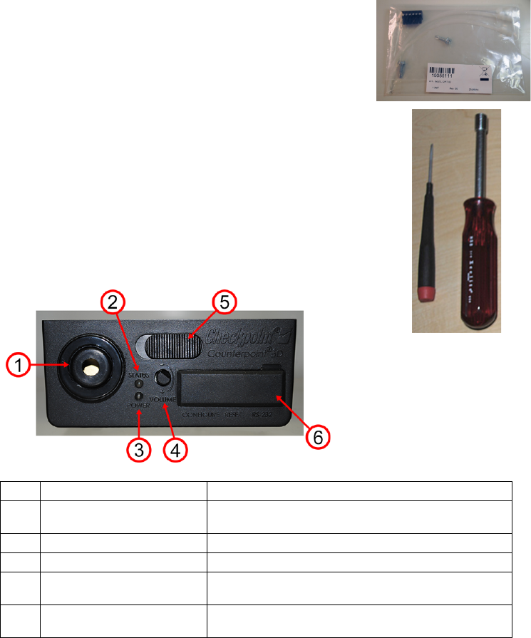
Install kit including:
2 #8 hex head screws (5/8 inch long)
2 tie wraps
1 6-Pin connector
Tools Req uired
1 small flathead screwdriver
1 1/4 inch nut driver
Optional
DMS Version 1.8.95 or later (required for setup of advanced features)
Operation/Features
Front
1 Sounder Sounder for alarm annunciation
2 Status LED Informs the User about device status. LED Functions are
defined in the label underneath the top plate.
3 Power LED (Green only) Indicates power
4 Volume Knob Adjusts sounder volume
5 Latch Allows user to remove unit for installing external connections
(e.g., cable for Antenna Pad, key switch or lock/trigger)
6 Rubber Boot Conceals DIP Switches, Reset Button and DMS Connection
port
Checkpoint Systems, Inc. – Field Service Installation Document – CKP P/N 10073883
Page 2 of 7
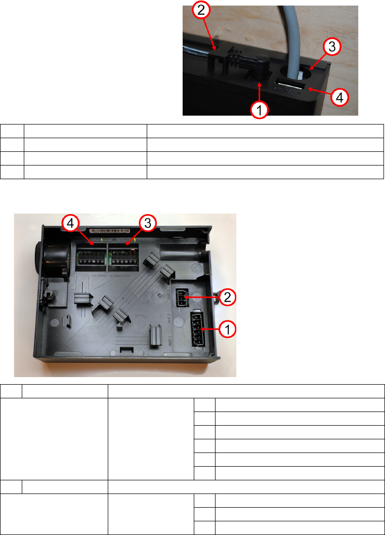
Rear
Inside
This is what you find,
pre-install with chassis
cover (plate) removed.
1 Input Power Connector Connector for +12V DC input power
2 DC Jack Strain Relief Strain relief for power cord
3 Internal Cabling exit Opening for all cables that connect internally (e.g., Antenna Cable)
4 USB Connector Connector for future USB functionality
1 Antenna 1 and 2 Primary RF Connection for 2 antennas max. (parallel)
Pin-out 1 ANT2+
2GND
3ANT2-
4ANT1+
5GND
6ANT1-
2 Antenna 3 Secondary RF Connection for another supported antenna
Pin-out 1 ANT3+
2GND
3ANT3-
Quick Start Guide: Counterpoint iD
Page 3 of 7
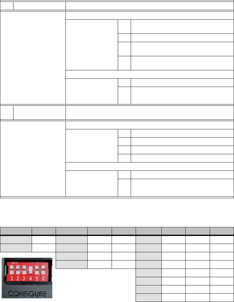
DIP Switch Functions
3 Alarm and Interlock Connection for Interlock and Alarm
Interlock Description / Pin-out
Interlocks are external
devices that relay
control signals to the
device
1 Interlock Input. Default is shorted to Pin 2 using
wire jumper
2GND
3 Interlock Opto, polarity independent (jumper
must be removed prior to use).
4 Interlock Opto, polarity independent (jumper
must be removed prior to use)
Alarm Description / Pin-out
The alarm output
supports generic
sounder devices and
external LEDs
5+12V
6Alarm -
4 +12V Auxiliary Output
and GPIO
Connection for GPIO and +12V output
GPIO Description / Pin-out
General Purpose
Input Output
1 GPO RLY, 1A max resistive load
2 GPO RLY, 1A max resistive load
3 GPI+, 3.3V through 10k Ohm
4GND
+12V Description / Pin-out
This set of terminal
pins is used to
connect devices that
require 12V
5 +12V, 100mA max
6GND
Selection Switch 1 Selection Switch 2 Switch 3 Selection Switch 4 Switch 5 Switch 6
High Power OFF Mode 5 OFF OFF Min Gain OFF OFF OFF
Low Power ON Mode 6 ON ON Gain 2 OFF OFF ON
Mode 4 OFF ON Gain 3 OFF ON OFF
Verification ON OFF Gain 4 OFF ON ON
Gain 5 ON OFF OFF
Gain 6 ON OFF ON
Gain 7ONONOFF
Max Gain ON ON ON
Checkpoint Systems, Inc. – Field Service Installation Document – CKP P/N 10073883
Page 4 of 7
Status LED Functions
*Future Release
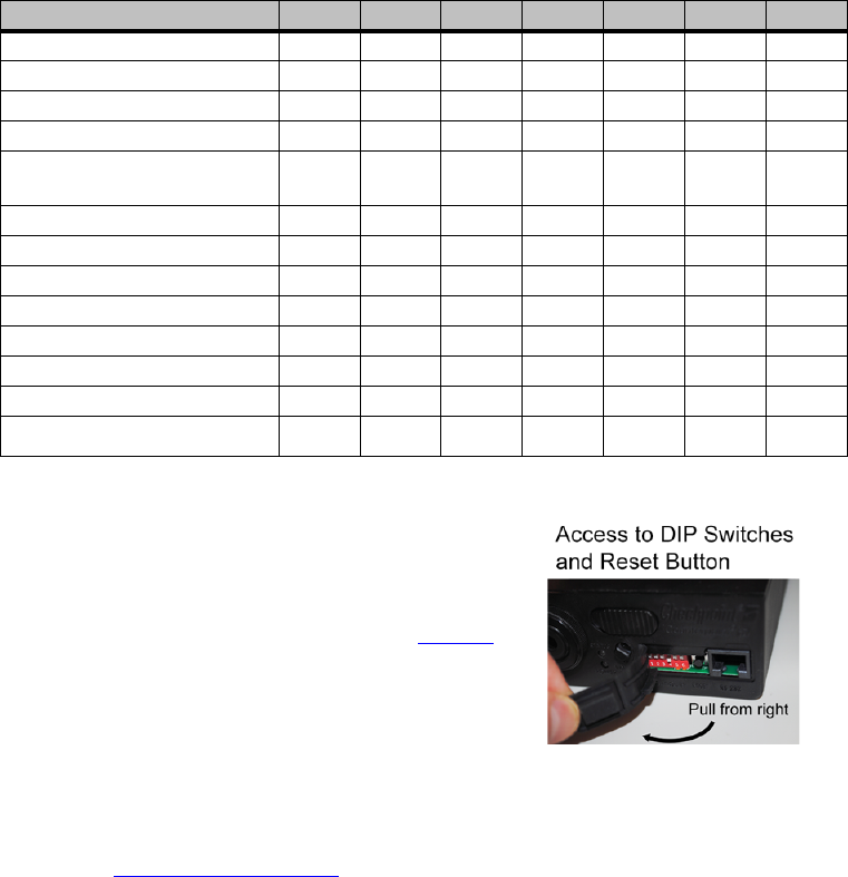
Reset Button
This button resets the unit and auto-tunes the
antenna under certain conditions. See Tuning
on page 7.
DMS Setup
Some features of CPiD are able to adjusted / applied without DMS, others are
not. For example, DMS is required to enable the secondary transmitter.
(Click here for FSWP link. Download DMS Version 1.8.95 or later.)
GPIO
The default system configuration has the following GPIO functions:
• GPO – Primary Alarm Relay
• GPI – Disabled
Any other functionality needs require DMS.
Status LED Function Red Yellow Blue Teal White Violet Green
Detection (Tag Alarm) X
Waiting for Interlock X
Keyswitch disabled X
AutoTune Blink
Auto Tune Window 0.5s after
reset is
pressed
Auto Tune Error X
Antenna Overvoltage Blink
Mistuned Blink Blink
Verification Mode X
Mode 4 X*
Mode 5 X*
Mode 6 X*
Factory Default Settings Blink at
power up
Quick Start Guide: Counterpoint iD
Page 5 of 7
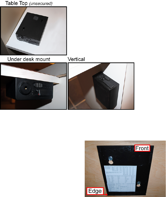
Mounting
A secure location, such as behind an access door below the register, is ideal for
mounting. Plan routing and location so the unit will not be struck by anything.
When possible, locate unit such that user has ability to interface with device.
Consult the SOW when provided. Customer may prefer / request no access.
Volume can only be muted in DMS. Choose 1 of the following orientations:
Figure 1: Typical Orientations
Top plate has front and rear. Install with edge in rear (away from user). User
can remove entire chassis to change configuration or adjust power.
If mounting permanently, install 2 hex head
screws using top plate as a template for the
2 screw locations.
• Do not install chassis with front
against a surface that can block
access or prevent assembly.
• Always release the front latch to
remove the chassis or top plate.
• View front labels to ensure unit will achieve correct orientation. An
easy visual cue is with the Sounder on the left.
Checkpoint Systems, Inc. – Field Service Installation Document – CKP P/N 10073883
Page 6 of 7
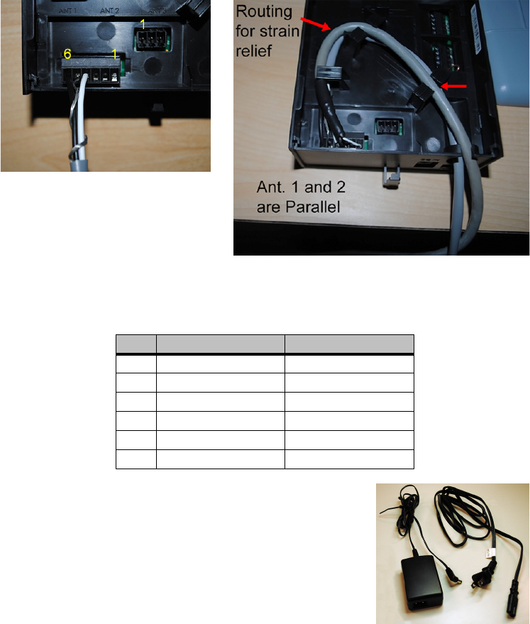
Wiring Procedure
1. Connect antenna cable(s) according to Table on page 2. Plug into ANT1 ANT2
connector, then route cable(s) through the clips for strain relief. Dog-bone excess
antenna cable with provided tie wrap.
Figure 2: Antenna Wiring, Primary Connection (Cable Routing on right)
2. If there are peripherals such as a Key Switch or an external scanner Interlock to
connect, use the following table for the wiring pin-out:
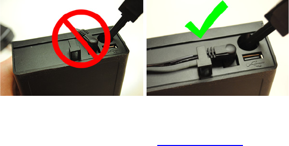
3. Connect AC cord to PSU. Connect PSU to chassis rear
DC Input and slide jack behind the strain relief as
shown in Figure 4 below. Route cabling to avoid
snags. If necessary, use tie wrap to bundle excess.
Figure 3: PSU and Regional AC Cord
Pin # Interlock/Alarm (J6) GPIO/12V (J5)
1 INTLK+ GPO RLY
2 GND GPO RLY
3 INTLK (OPTO) GPI+
4 INTLK (OPTO) GND
5ALARM+ +12V
6 ALARM- GND
Quick Start Guide: Counterpoint iD
Page 7 of 7
Figure 4: PSU DC Cord Strain Relief
4. Configure the DIP Switches on the front panel for the desired operation.
Note: For details on “Mode Configurations”, see DIP Switch Functions on page 3 above.
5. System is ready to power ON. With no advanced features required, the final step is
to press Reset button, wait for the Violet LED, then press reset again to tune.
6. Optional: Connect field service laptop to front RS-232 port via patch cable, then
perform any FW upgrades or advanced tuning with DMS. See Help File for more.
Tuning
CPiD needs to be tuned upon installation or it will not function.
Using DMS SW features (see below), advanced antenna tuning may help
achieve desired detection, but keep in mind:
• Avoid interactions when located near EAS pedestal/antennas.
• Tune system for immunity/ False Alarms for the detector.
See Also
DMS version 1.8.95 and later will feature a help file to cover all SW-based
configurations and settings for using CPiD. To access the instructions, click
Help (or press F1) > Help Files > Counterpoint ID.

Appendix A: Regulatory and Safety
Page A-1
Important Information to our Users in North America
FCC Regulatory Compliance Statement
Checkpoint Systems, Inc., offers Electronic Article Surveillance (EAS) or Radio Frequency
Identification Products that have been FCC certified or verified to 47 CFR Part 15 Subparts B/C.
Appropriately, one of the following labels will apply to the approval:
NOTE: This equipment has been tested and found compliant within the limits for a class A digital
device, pursuant to Part 15 of the FCC Rules. These limits are designed to provide reasonable
protection against harmful interference when the equipment is operated in a commercial environment.
This equipment generates, uses, and can radiate interference to radio communications. Operation of
this equipment in a residential area is likely to cause harmful interference in which case the user will be
required to correct the interference at own expense.
- OR -
This device complies with Part 15 of the FCC Rules. Operation is subject to the following two
conditions: (1) including this device may not cause harmful interference, and (2) this device must
accept any interference received, including interference that may cause undesired operation, which
may include intermittent decreases in detection and/or intermittent increases in alarm activity.
Industry Canada Regulatory Compliance Statement
This device complies with the Industry Canada license-exempt RSS standard(s). Operation is subject to the
following two conditions:
1. This device may not cause interference, and
2. This device must accept any interference, including interference that may cause undesired oper-
ation of the device.
Under Industry Canada regulations, this radio transmitter may only operate using an antenna of a type
and maximum (or lesser) gain approved for the transmitter by Industry Canada. To reduce potential
radio interference to other users, the antenna type and its gain should be so chosen that the equivalent
isotropically radiated power (e.i.r.p.) is not more than that necessary for successful communication.
This radio transmitter (IC: 3356B-CPID) has been approved by Industry Canada to operate with the
antenna types listed below with the maximum permissible gain and required antenna impedance for
each antenna type indicated. Antenna types not included in this list, having a gain greater than the
maximum gain indicated for that type, are strictly prohibited for use with this device.
Antenna Type Antenna Structure Antenna Size
Counterpoint pad 1 turn loop 12” x 12”
Royston antenna 1 turn loop 13” x 6”
NCR 7876 2 turn loop 8.5” x 6.5”
NCR 7878 1 turn loop 6” x 6”

Page A-2
Equipment Compliance Statement
Conveyor
Deactivation Pad
1 turn loop 9.8” x 9.8”
Handheld deactivator 1 turn loop 10” x 8”
Hand scan antenna 1 turn loop 6.8” x 1.5”
Sheet deactivator 1 turn loop 9.4” x 9.4”
Magellan 8400/9800 1 turn loop 8” x 8”
Metrologic MS2420 1 turn loop 8” x 8”
Motorola MP6000 1 turn loop 8” x 8”
Antenna Type Antenna Structure Antenna Size
Checkpoint’s Electronic Article Surveillance (EAS) products have been designed for safeness during normal
use and, where applicable have been certified, listed, or recognized in accordance with one or more of the
following safety standards; UL 60950-1, CSA C22.2 No. 60950-1-07. Additional approvals may be pending.
WARNING:
Changes or modifications to Checkpoint’s EAS or Radio Frequency Identification (RFID)
equipment not expressly approved by the party responsible for assuring compliance could void the user’s
authority to operate the equipment in a safe or otherwise regulatory compliant manner.

Appendix A: Regulatory and Safety
Page A-3
Important Information to our Users in Europe
CE Regulatory Compliance Statement
Where applicable, Checkpoint Systems, Inc. offers certain Electronic Article Surveillance (EAS)
products that have CE Declarations of Conformity according to R&TTE Directive 99/5/EC, EMC
Directive 2004/108/EC, and Low Voltage Directive 2006/95/EC.
System Electromagnetic Compatibility (EMC) has been tested and notified through Spectrum
Management Authorities if necessary, using accredited laboratories, whereby, conformity is declared
by voluntarily accepted European Telecommunications Standards Institute (ETSI) standards EN
301489-3 and EN 302208 and/or EN 300330, as applicable.
NOTE: Certain Electronic Article Surveillance (EAS) equipment have been tested and found to
conform to the CE emission and immunity requirement in Europe. This equipment generates,
uses, and can radiate radio frequency energy and, if not installed and used in accordance with
the instruction manual, may cause harmful interference to radio communications. Under
unusual circumstances, interference from external sources may degrade the system
performance, which may include intermittent decreases in detection and/or intermittent
increases in alarm activity. However, there is no guarantee that interference will not occur in a
particular installation. If this equipment experiences frequent interference from external sources
or does cause harmful interference to radio communications reception, which can be
determined by turning the equipment off and on, please contact a Checkpoint Systems
representative for further assistance.
RoHS Compliance Statement
The RoHS Directive stands for "the restriction of the use of certain hazardous substances in electrical
and electronic equipment." A RoHS compliant product means that electrical and electronic equipment
cannot contain more than maximum permitted levels of lead, cadmium, mercury, hexavalent
chromium, polybrominated biphenyl (PBB) and polybrominated diphenyl ether (PBDE). Checkpoint is
in compliance with the RoHS directive.
WEEE Compliance Statement
The Waste Electrical and Electronic Equipment Directive (WEEE) applies to companies that
manufacture, sell, distribute, or treat electrical and electronic equipment in the European Union. There
are a number of obligations imposed on Checkpoint as a supplier of electrical and electronic
equipment. Checkpoint's compliance approach for each of these obligations is provided below.
Page A-4
WEEE Marking
All products that are subject to the WEEE Directive supplied by Checkpoint are compliant with the WEEE
marking requirements. Such products are marked with the "crossed out wheelie bin" WEEE symbol shown
below in accordance with European Standard EN 50419.
Information for Users
According to the requirements of European Union member state WEEE legislation, the following user
information is provided in English for all Checkpoint supplied products subject to the WEEE directive.
This symbol on the product or on its packaging indicates that the product must not
be disposed of with normal waste. Instead, it is your responsibility to dispose of
your waste equipment by arranging to return it to a designated collection point for
the recycling of waste electrical and electronic equipment. By separating and
recycling your waste equipment at the time of disposal you will help to conserve
natural resources and ensure that the equipment is recycled in a manner that
protects human health and the environment. For information about how to recycle
your Checkpoint supplied waste equipment, please contact the Checkpoint
Systems, Inc. Field Service office in your region. Customers can obtain this
information from their system User’s Guide.
REACH Compliance Statement
The European REACH Regulation 1907/2006 on Registration, Evaluation, Authorization, and Restriction of
Chemicals (REACH), Annex XVII entered into force in June 2009, and affects all companies producing,
importing, using, or placing products on the European market. The aim of the REACH regulation is to
ensure a high level of protection of human health and the environment from chemical substances.
Checkpoint Systems’ substances management system follows and complies with the current revision of the
REACH Regulation on the substances as identified by ECHA (European Chemical Agency).
Checkpoint Systems’ products are considered articles as defined in REACH Article 3 (3).
These products/articles under normal and reasonable conditions of use do not have intended release of
substances. Therefore the requirement in REACH Article 7 (1) (b) for registration of substances contained in
these products/articles does not apply.
Checkpoint Systems’ products/articles do not contain Substances of Very High Concern or if there are
SVHC in the product/article, the content is less than the 0.1% (wt/wt) as defined by REACH Article 57,
Annex XIV, Directive 67/548/EEC. Therefore the requirement in REACH Article 7 (2) to notify ECHA if a
product/article contains more than 0.1% wt/wt of an SVHC and tonnage exceeding 1 tonne per importer per
year is not applicable.
Checkpoint Systems’ European operations do not manufacture or import chemicals, therefore Checkpoint
Systems has no obligation to register substances.
Packaging Compliance Statement
No CFCs (chlorofluorocarbons), HCFCs (hydrofluorocarbons) or other ozone depleting sub-stances are
used in packaging material. Chromium, lead, mercury, or cadmium are not intentionally added to packaging
materials and are not present in a cumulative concentration greater than 100 ppm as incidental impurities.
No halogenated plastics or polymers are used for packaging material. Checkpoint complies with the EU
Directive 94/62/EEC.