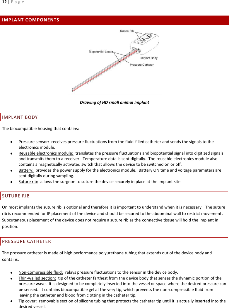
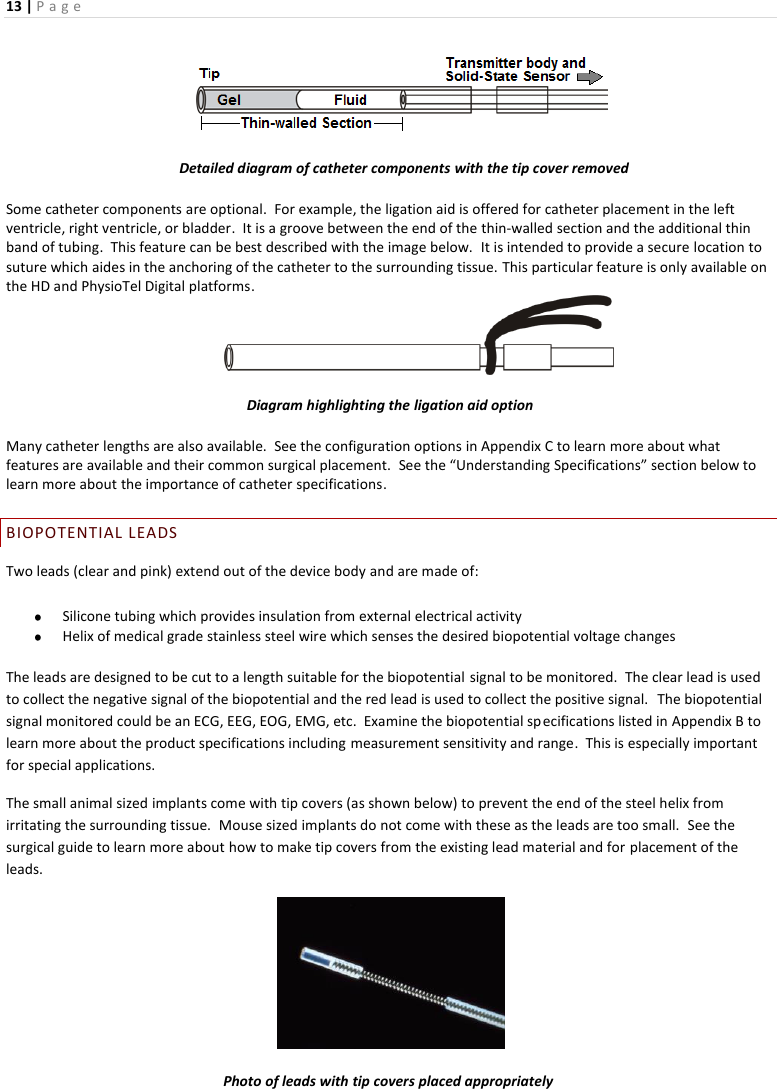
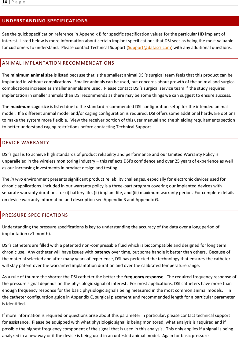
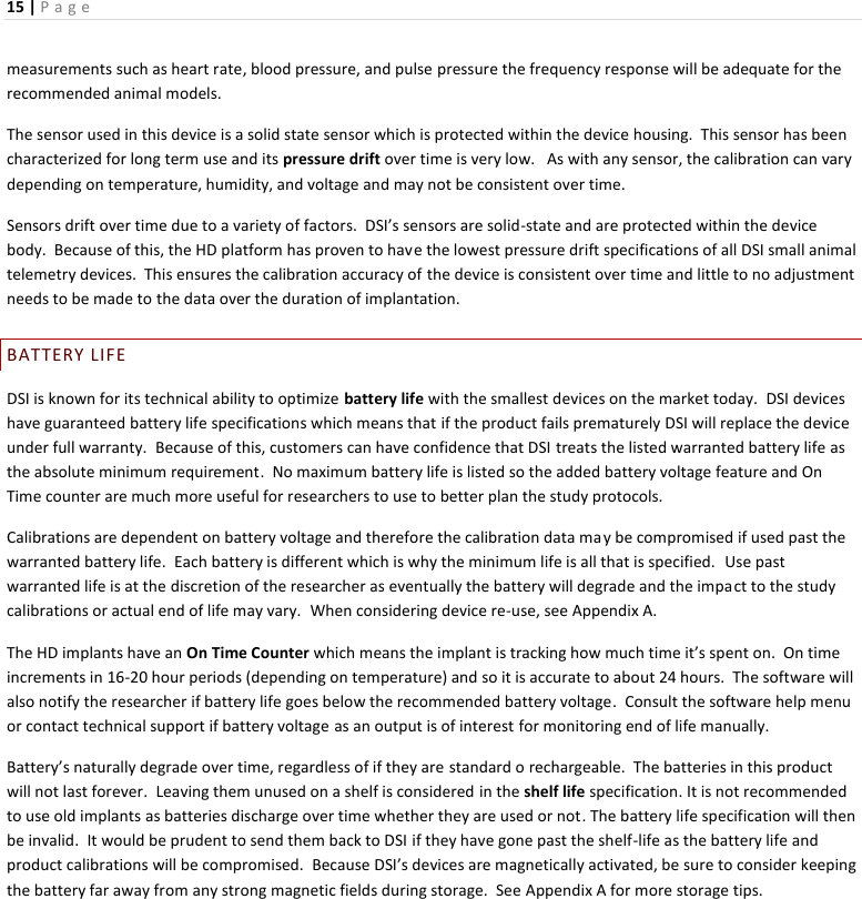
Data Sciences HD18 Small Animal Implant Transmitter User Manual Getting Started Guide
Data Sciences International Inc Small Animal Implant Transmitter Getting Started Guide
UserManual.wiki
>
Data Sciences
>
HD18 User Manual
>
Users Manual
Contents
1.
Users Manual
2.
Users Manual Requirements
Users Manual
Navigation menu
Upload a User Manual
Namespaces
Wiki Guide
HTML
PDF
Info
Views
User Manual
Discussion / Help
Navigation
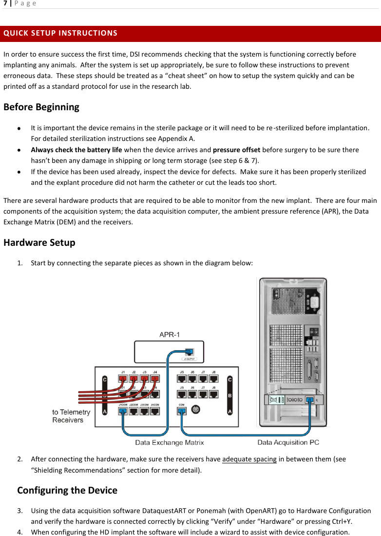
![9 | P a g e g. However, if the offset is greater than the specified drift and is still within the sterile packaging contact DSI’s technical support as they will help you determine how to proceed with the use of this pressure implant. h. If the product has been sitting on the shelf for a few months or if it this is a used implant technical support may recommend entering a pressure offset into the software to account for pressure drift over time at body temperature. Never enter a pressure offset into the software without checking the device at the appropriate temperatures. Follow the instructions in the “Instructions for Implant Use” section for the most accurate method to determine the actual pressure offset at body temperature and to learn how to enter the pressure offset into the software platform. Begin Surgery 7. Once the device is configured and properly checked for functionality surgery can start. 8. Remember, for pressure products it is important to hydrate the catheter for a minimum of 15-30 minutes in sterile saline. Remove the protective tip cover on the catheter before implantation under sterile conditions. If needed, re-gel the catheter using a re-gel syringe right before surgery. For explicit instructions on how to re-gel go to DSI’s website for a tech note and video or read the surgical manual. 9. Always keep the DSI provided surgical manual nearby to ensure the surgery is being performed correctly as this is a critical step to the success of the study and to maintain the best care for the animal. Personal on-site training or surgical courses at DSI are available if a hands-on experience is desired. 10. When the catheters and leads are surgically placed, the physiological signals from the implanted device can be viewed in the software immediately during acquisition. 11. Give the animal at least 10-14 days to recover from surgery before collecting baseline data. This has been verified and proof sources are available. Information can be found by searching in the Bibliography section on our website. Please note DSI expects: a. Local inflammation, as expected from any surgery, will heal over time. b. Mean pressure will stabilize over time (approximately 4 hours) as the catheter and implant body acclimates to the in vivo hydrated and thermal environment. This timing may vary depending on if heating and hydrating of the catheter was performed before surgery and for how long. c. If conducting a pair house study, keep the animals apart for at least 10-14 days prior to placing them in the same cage. Formatted: Indent: Left: 0.75", No bullets ornumberingComment [K1]: Waiting to hear from Heather regarding this to verify the amount of time is correct.](https://usermanual.wiki/Data-Sciences/HD18.Users-Manual/User-Guide-2759080-Page-9.png)
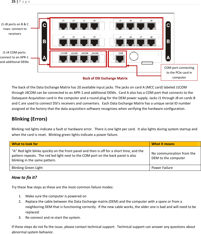
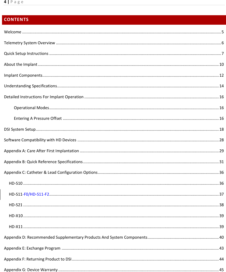
![27 | P a g e CAGING AND SHIELDING RECOMMENDATIONS DSI has experience using the typical shoe box sized cages but more and more customers are finding that lab space is difficult to come by. Many different configurations are possible depending on the animal model and space available. As a rule of thumb, always leave at a minimum the distance of one RPC-1 (~12 inches or 31cm) between cages. The best case situation would be placing each cage two receiver widths (18 inches or 45 cm) away from each other. Excluding pair housing studies, below is an example of the minimum recommended small animal configuration without any shielding: RPC-1RPC-1 RPC-1RPC-1RPC-1 RPC-1RPC-1RPC-1 As shown above, stagger the cages on a shelf to conserve the most space with this single frequency device. This illustration represents one implanted animal in each cage paired with another animal that is not implanted, With the HD-S11-F2 device, it is possible to pair two implanted animals with different frequency implants in the same cage and gather data simultaneously. The RPC-3 receiver is mandatory for pair housing studies and requires the same amount of distance between cages as that of the RSC-1 (~12 inches or 31cm). If the receivers need to be closer together and data loss is prevalent (>5%) implement electromagnetic shielding. Shielding comes in many forms from sheet metal and chicken wire to high tech clear specifically designed metal mesh. Locate the source of the noise and enclose that with shielding if possible. For example, the DEM or another implant can be a source of noise if it is placed too close to the receivers. If problems arise or if you require a list of acceptable shielding options, technical support is equipped to help determine the best shielding method either remotely or onsite if necessary. 12 inches 18 inches Comment [K2]: Pair house Deleted: ThisDeleted: ODeleted: can be implanted with telemetry, and Deleted: the otherDeleted: willDeleted: be Deleted: (if the study protocol requires paired housing the animal).](https://usermanual.wiki/Data-Sciences/HD18.Users-Manual/User-Guide-2759080-Page-27.png)
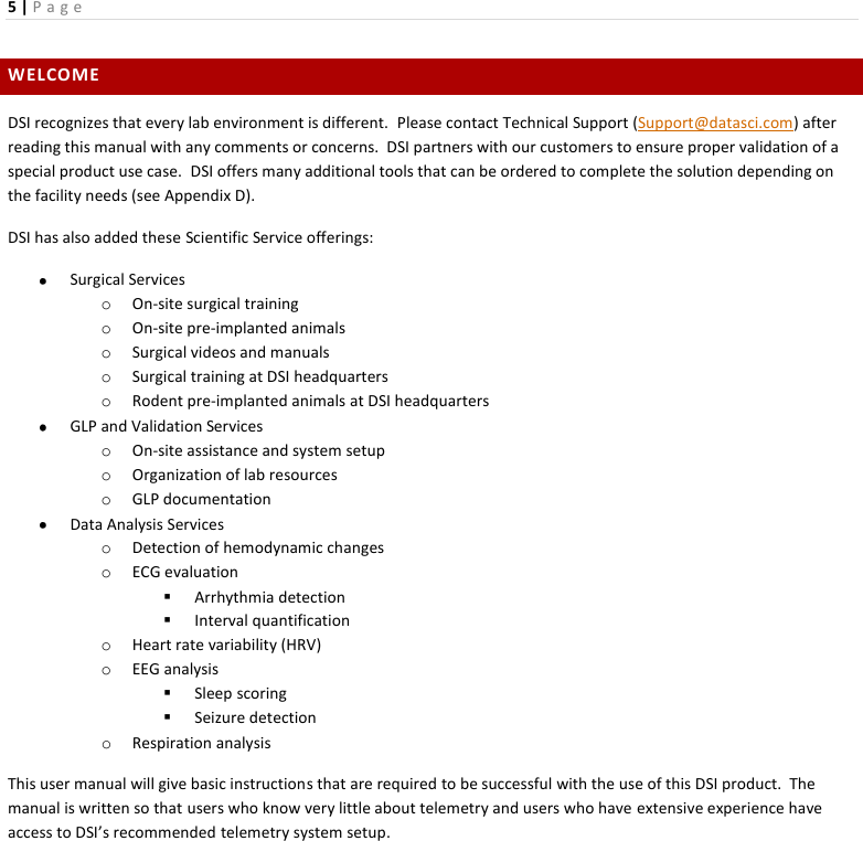
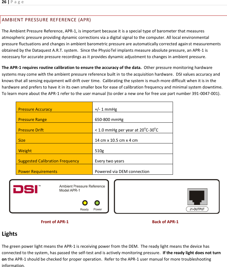
![28 | P a g e SOFTWARE COMPATIBILITY WITH HD DEVICES This matrix below explains the Dataquest ART, Ponemah and OpenART software versions (and service packs (SP) if necessary) required for each implant in the HD platform. Software Platform Version Implant HD-S21 HD-S11-F0 HD-S11-F2 HD-S10 HD-X11 HD-X10 Ponemah 5.0 ● ● (SP2) 5.1 ● ● (SP1) ● 5.2 ● ● ● ●(SP5) ● ●(SP5) 5.6 ● ● ● ● ● 6.1 ● ● OpenART & Dataquest ART 4.31 ● 4.32 ● ● 4.33 ● ● ● 4.34 ● ● ● 4.36 ● ● ● ● ● GLP REQUIREMENTS If the lab is GLP certified, or if it aspires to be, DSI implants will work within this environment. However, Ponemah is the only DSI software that can be validated for GLP compliant labs. Because of the HD device’s digitally transmitted animal ID, it is easier to track in vivo and verify that the correct animal is being used. Contact Scientific Services for more information on software validation services and how our experienced team can help save time and reduce costs associated with computer system validation. Formatted TableFormatted: Left, Space After: 0 pt, Linespacing: singleDeleted: ¶Deleted: ¶Comment [K3]: Talk to Chris](https://usermanual.wiki/Data-Sciences/HD18.Users-Manual/User-Guide-2759080-Page-28.png)
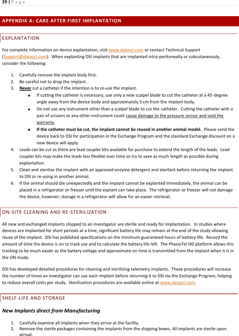
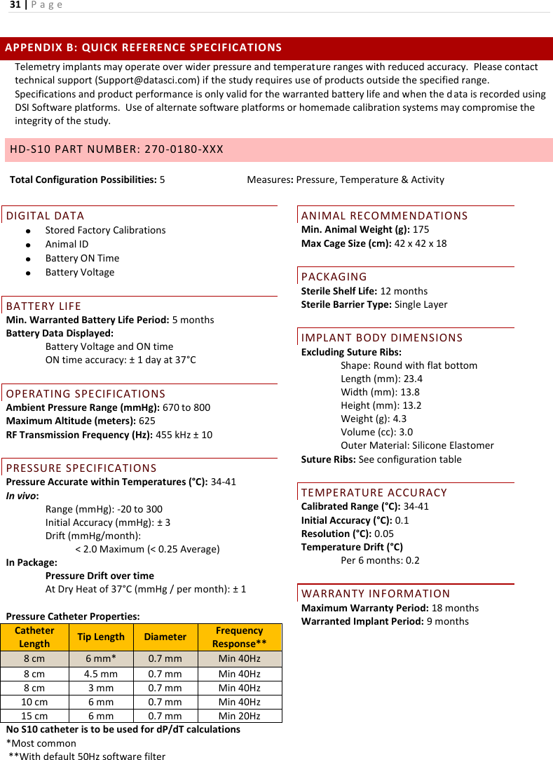
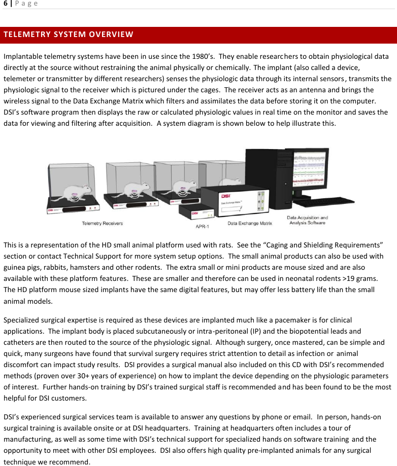
![32 | P a g e HD-S11-F0/-F2 PART NUMBER: -F0: 270-0193-XXX; -F2: 270-0196-XXX Total Configuration Possibilities: 10 Measures: Pressure, Biopotential, Temperature & Activity DIGITAL DATA Stored Factory Calibrations Animal ID Battery ON Time Battery Voltage BATTERY LIFE Min. Warranted Battery Life Period: 2 months Battery Data Displayed: Battery Voltage and ON time ON time accuracy: ± 1 day at 37°C OPERATING SPECIFICATIONS Ambient Pressure Range (mmHg): 670 to 800 Maximum Altitude (meters): 625 RF Transmission Frequency: 455 kHz (HD-S11-F0) 18 MHz (HD-S11-F2) PRESSURE SPECIFICATIONS Pressure Accurate within Temperatures (°C): 34-41 In vivo: Range (mmHg): -20 to 300 Initial Accuracy (mmHg): ± 3 Drift (mmHg/month): < 2.0 Maximum (< 0.25 Average) In Package: Pressure Drift over time At Dry Heat of 37°C (mmHg / per month): ± 1 Pressure Catheter Properties: ANIMAL RECOMMENDATIONS Min. Animal Weight (g): 175 Max Cage Size (cm): 42 x 42 x 18 PACKAGING Sterile Shelf Life: 12 months Sterile Barrier Type: Single Layer IMPLANT BODY DIMENSIONS Excluding Suture Ribs: Shape: Flat with rounded edges Length (mm): 34.8 Width (mm): 17.6 Height (mm): 12.0 Weight (g): 8 Volume (cc): 5.9 Outer Material: Silicone Elastomer Suture Ribs: See configuration table TEMPERATURE ACCURACY Calibrated Range (°C): 34-41 Initial Accuracy (°C): 0.15 Resolution (°C): 0.05 Temperature Drift (°C) First two weeks: 0.1 Per 6 months after: 0.1 BIOPOTENTIAL SPECIFICATIONS Bandwidth Range (Hz): 0.1 - 145 Input Voltage Range (mV): ± 5 Biopotential Lead Dimensions Length (cm): 30cm or 60cm Outer Diameter (mm): 0.94 Coil Diameter (mm): 0.46 WARRANTY INFORMATION Maximum Warranty Period: 18 months Warranted Implant Period: 9 months Catheter Length Tip Length Diameter Frequency Response 8 cm 6 mm* 0.7 mm Min 100Hz 8 cm 4.5 mm 0.7 mm Min 100Hz 8 cm 3 mm 0.7 mm Min 100Hz 10 cm 6 mm 0.7 mm Min 50Hz 15 cm 6 mm 0.7 mm Min 20Hz *Most common and is only catheter recommended for dP/dt calculation Deleted: (Hz)Deleted: ± 10 Formatted: Font: Not BoldComment [K4]: Perry – does this need a +/- 10 like the 455kHz? Formatted: Font: Not Bold](https://usermanual.wiki/Data-Sciences/HD18.Users-Manual/User-Guide-2759080-Page-32.png)