ELTA ADT406 ELT 406 MHz (Emergency Locator Transmitter) User Manual
ELTA ELT 406 MHz (Emergency Locator Transmitter)
UserManual.wiki
>
ELTA
>
ADT406 User Manual
>
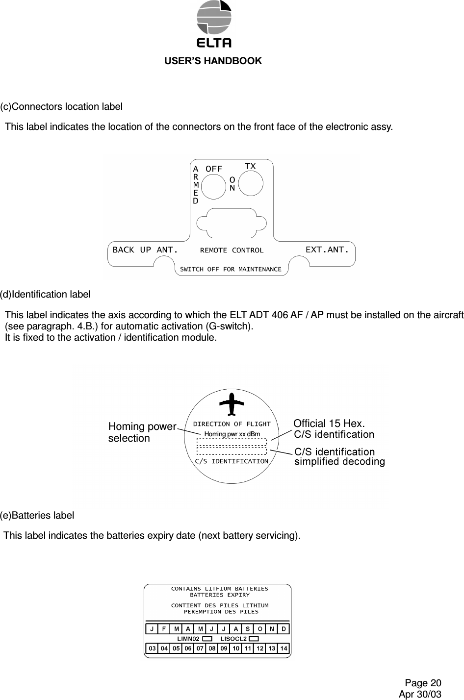
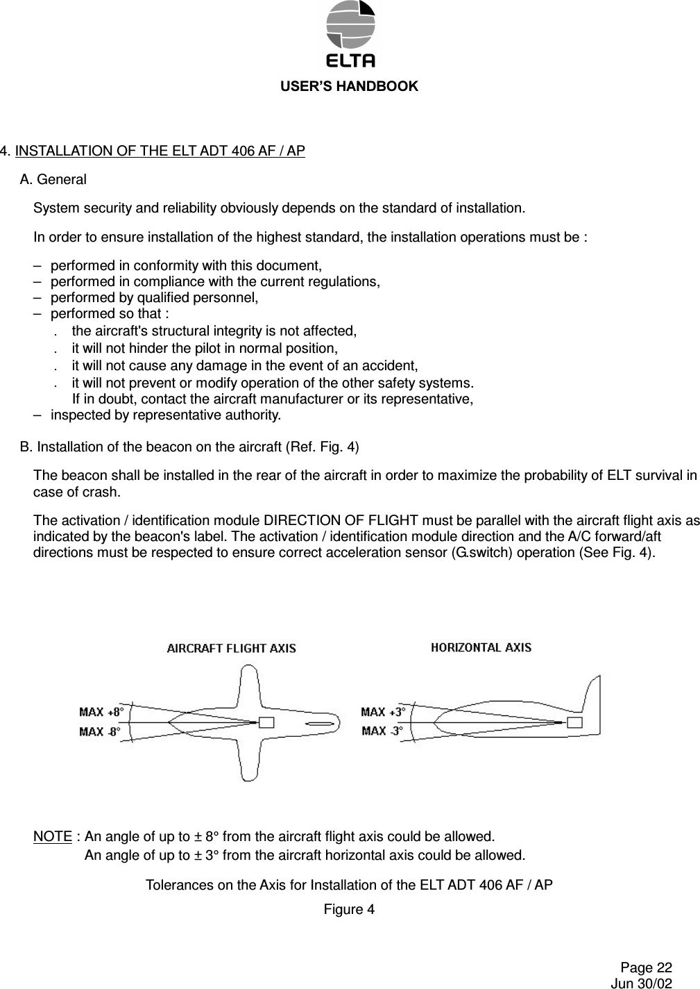
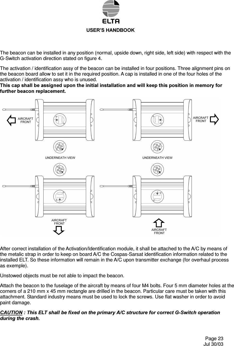
ADT 406 AF AP users handbook
Contents
1.
ADT 406 AF AP users handbook
2.
ADT 406 AP users handbook
ADT 406 AF AP users handbook
Navigation menu
Upload a User Manual
Namespaces
Wiki Guide
HTML
PDF
Info
Views
User Manual
Discussion / Help
Navigation


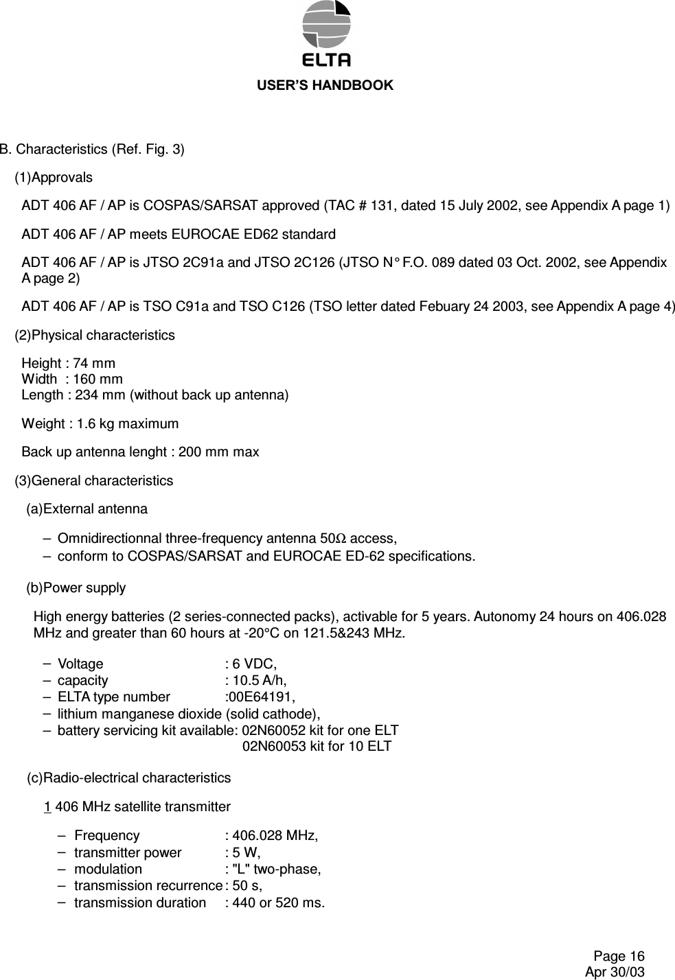
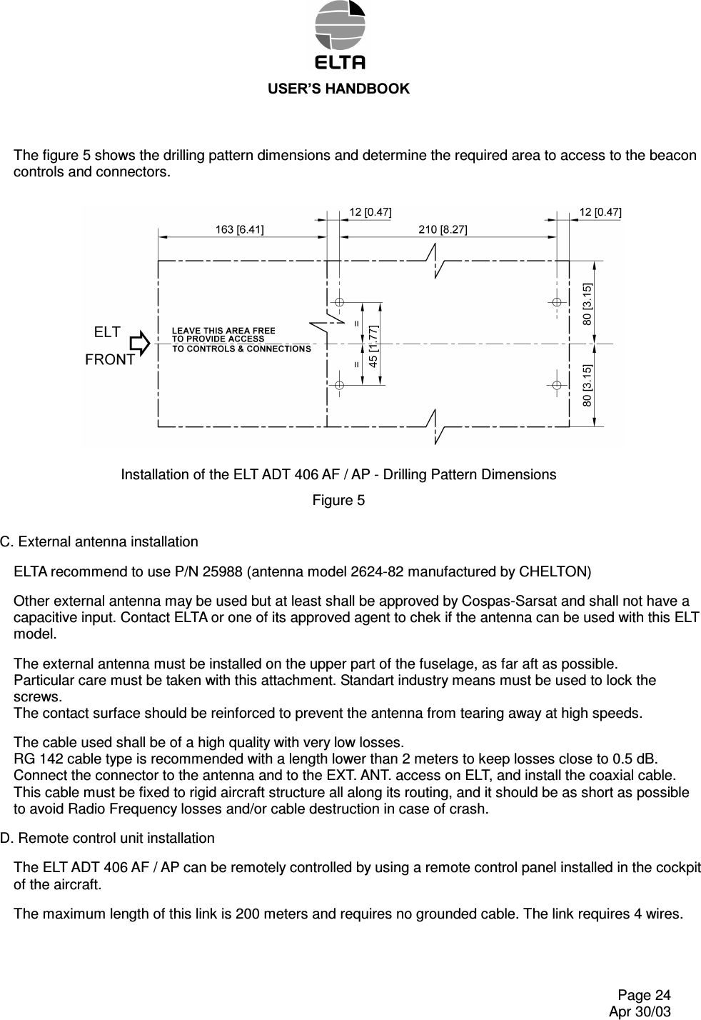
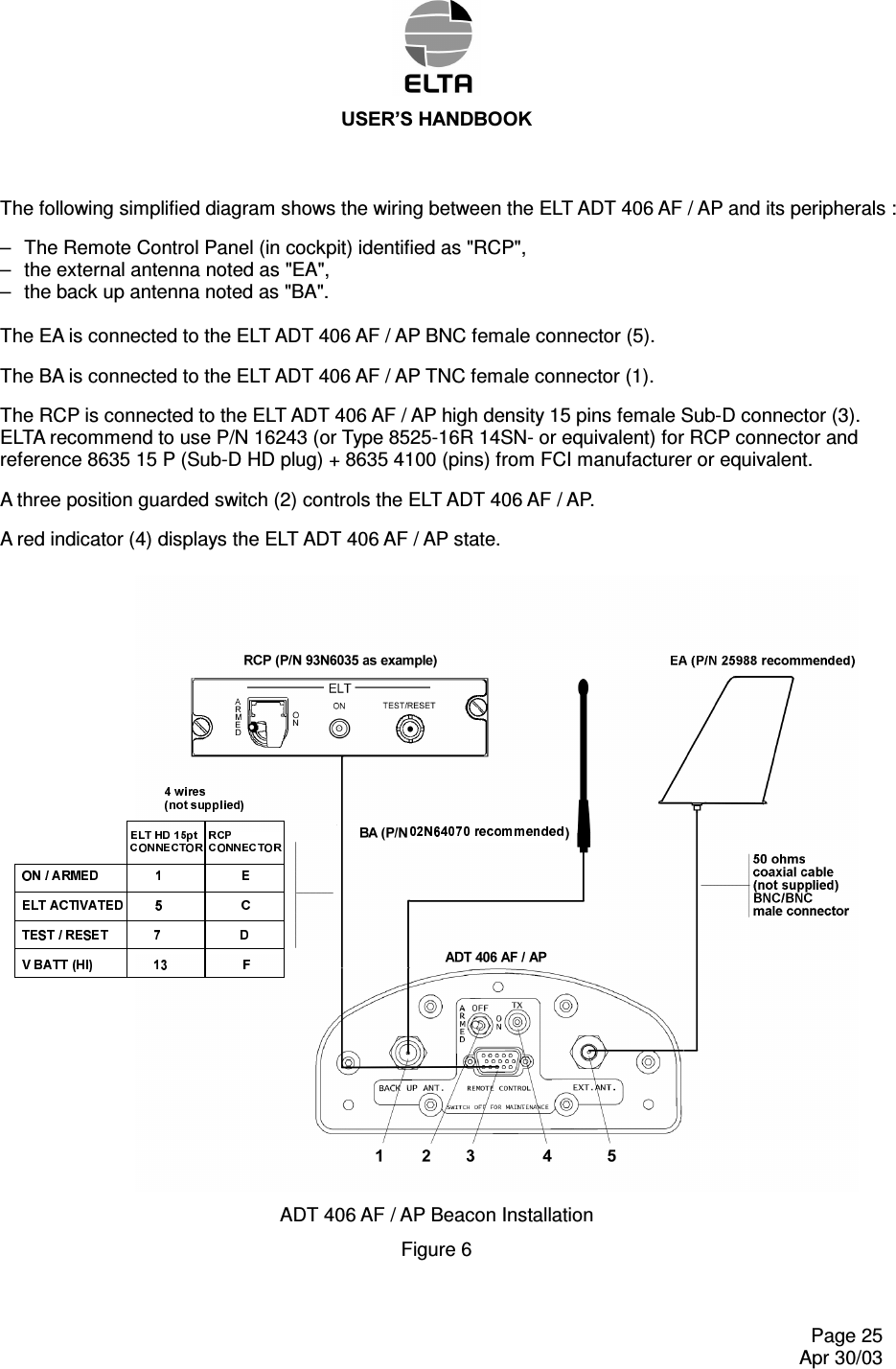
![86(5¶6+$1'%22. Page 15 Apr 30/03 ELT ADT 406 AF /AP - Overall Dimensions (Other Back Up Antenna Configuration Are Available) Figure 3 205 [8.07]74 [2.91]](https://usermanual.wiki/ELTA/ADT406.ADT-406-AF-AP-users-handbook/User-Guide-354620-Page-16.png)