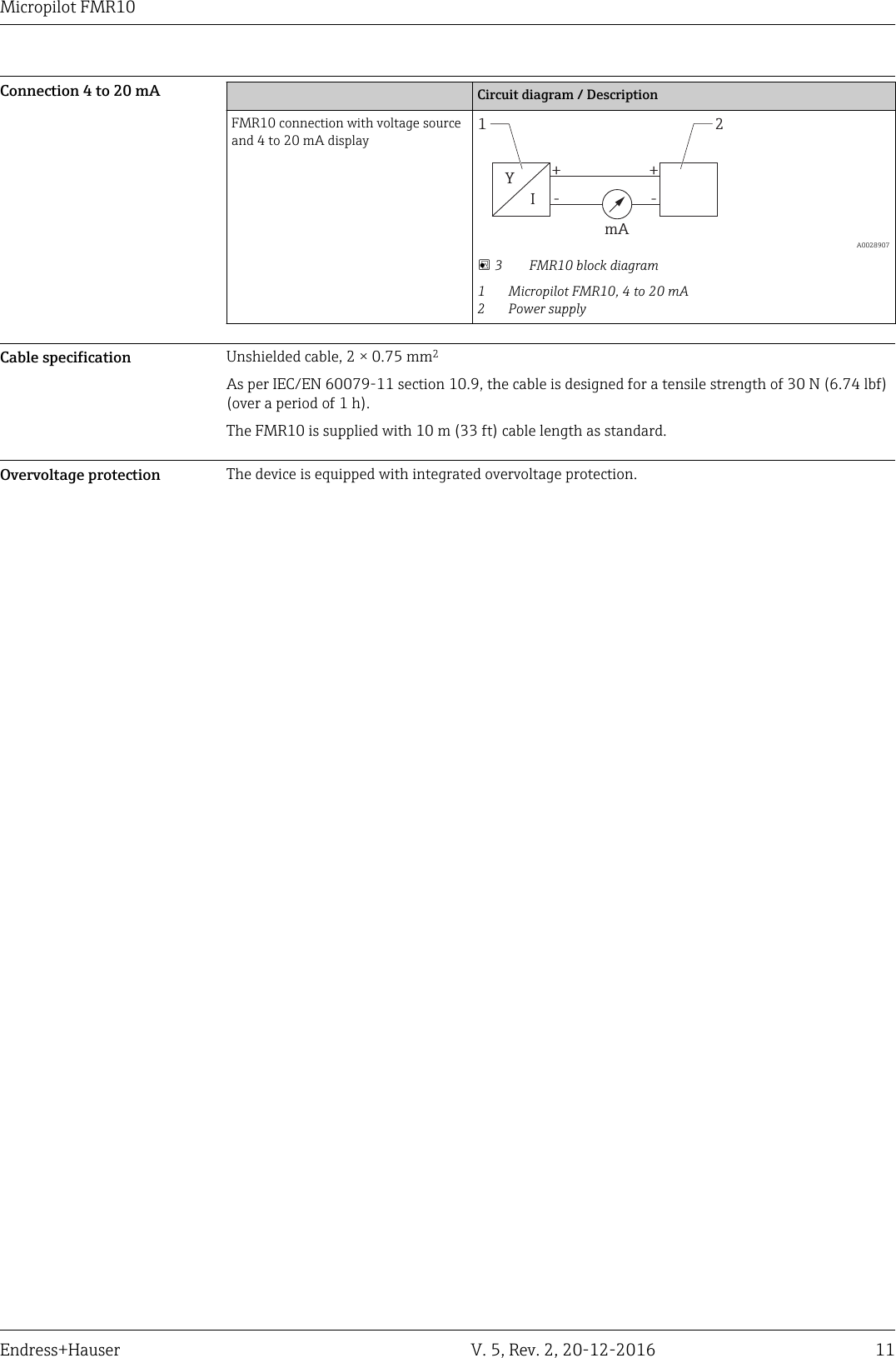
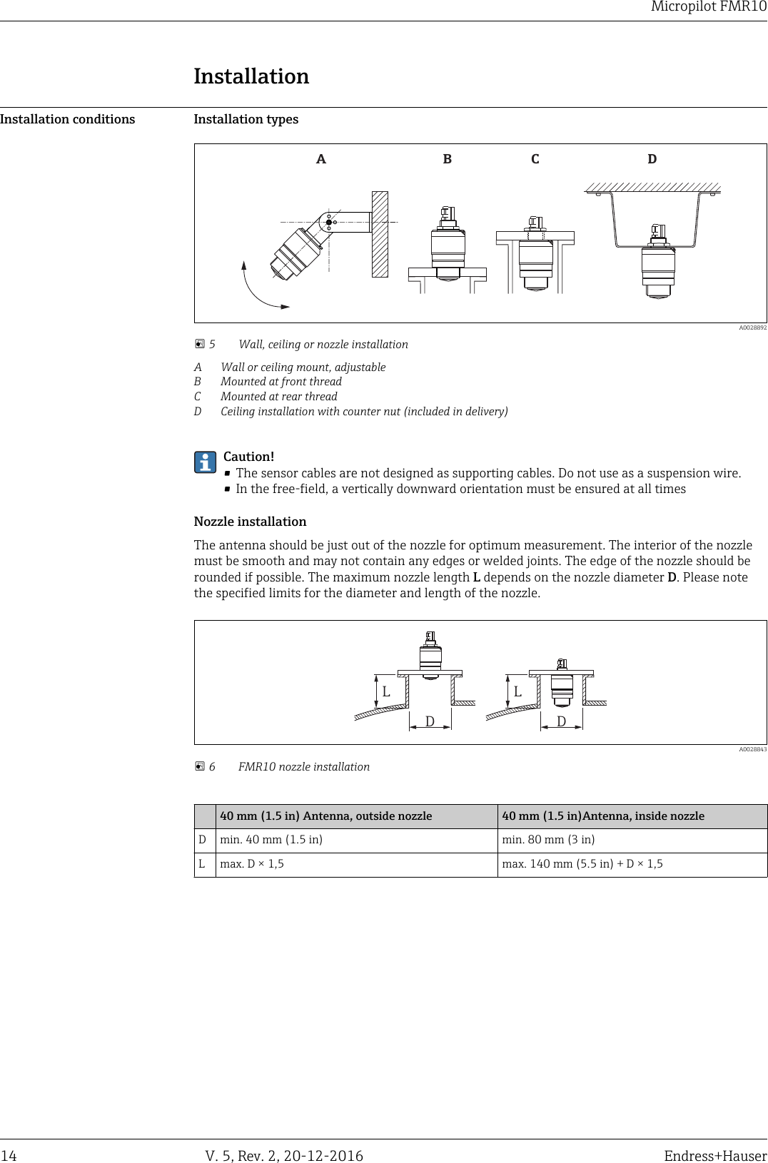
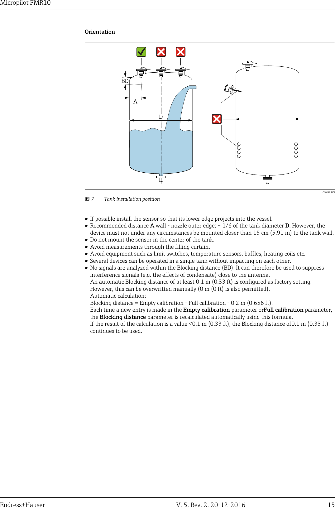
Endress and Hauser and Co FMR2XKF Level-probing Radar User Manual Micropilot FMR10
Endress and Hauser GmbH and Co Level-probing Radar Micropilot FMR10
UserManual.wiki
>
Endress and Hauser and Co
>
FMR2XKF User Manual
>
User Manual FRM10
Contents
1.
User Manual FRM10
2.
User Manual FRM20
User Manual FRM10
Navigation menu
Upload a User Manual
Namespaces
Wiki Guide
HTML
PDF
Info
Views
User Manual
Discussion / Help
Navigation
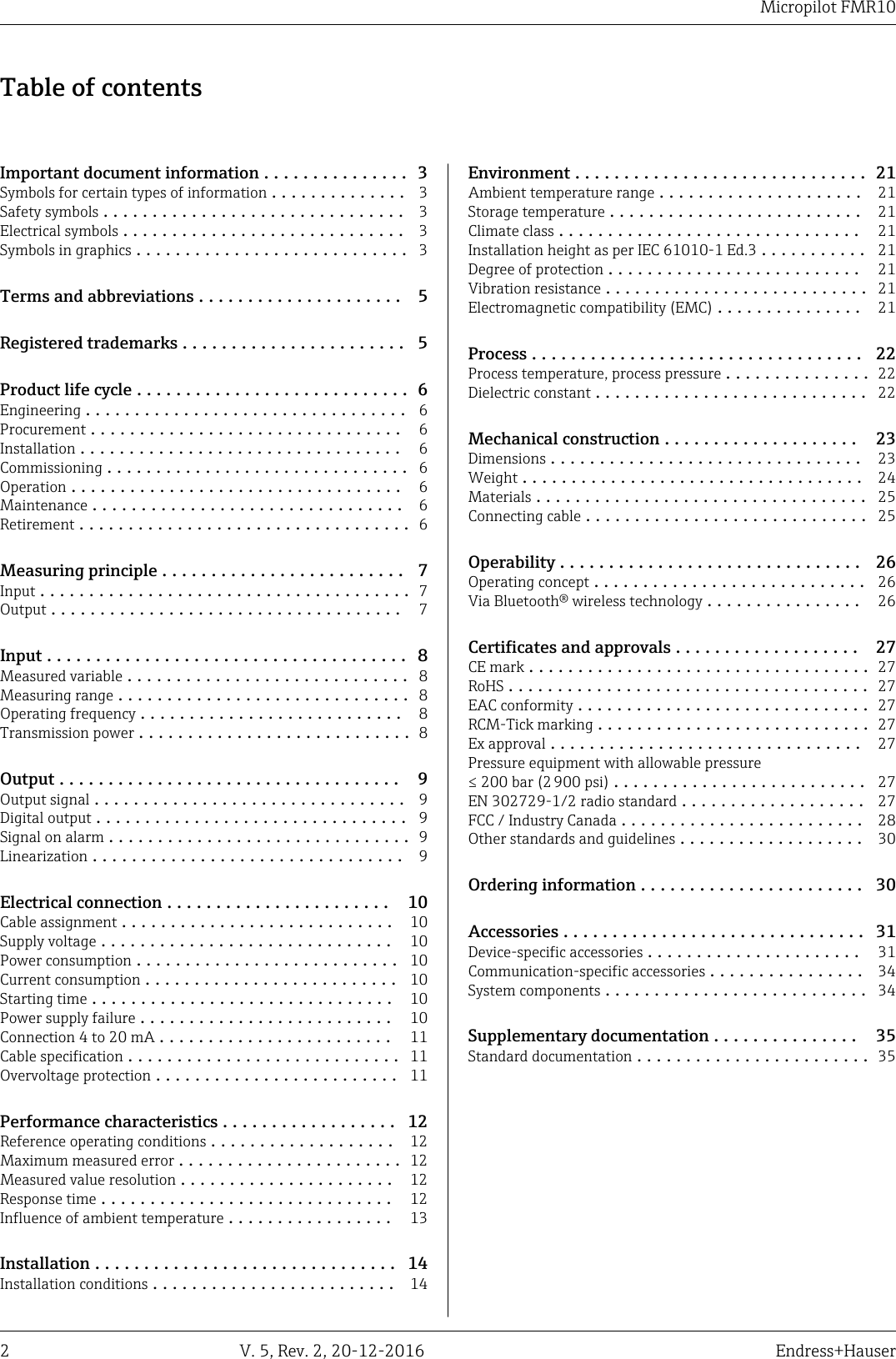
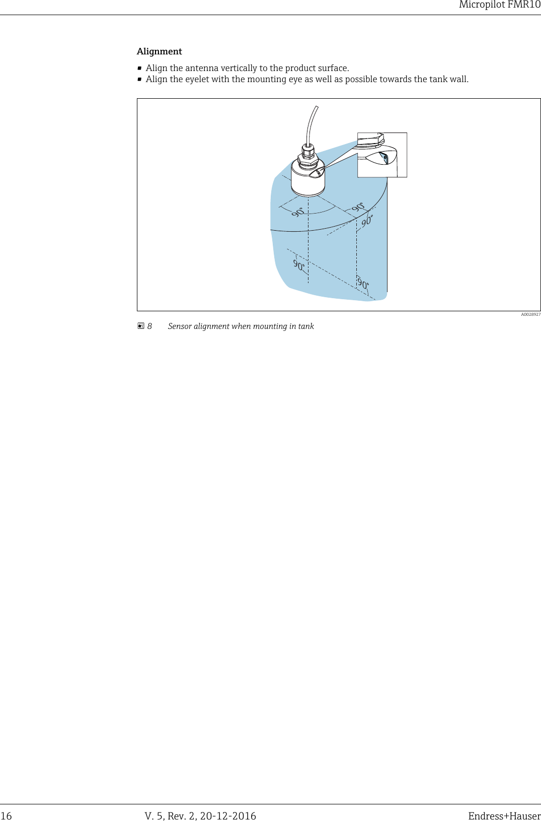
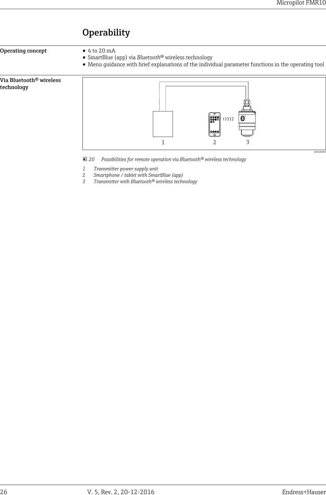
![Micropilot FMR1010 V. 5, Rev. 2, 20-12-2016 Endress+HauserElectrical connectionCable assignment-+12 A0028954 2 Cable assignment1 Plus, brown wire2 Minus, blue wireSupply voltage An external power supply is necessary.Terminal voltage U at device Maximum load R, depending on supply voltage U0 of power supplyunit10.5 to 30 VDC 2-wireR [ ]WU0[V]1010.5 21.7520 300500 A0029226Potential equalizationNo special measures for potential equalization are required.Various power supply units can be ordered from Endress+Hauser.Battery operationThe sensor's Bluetooth® wireless technology communication can be disabled to increase theoperating life of the battery.Power consumption Maximum input power: 675 mWCurrent consumption • maximum input current: <25 mA• Maximum start-up current: 3.6 mAStarting time First stable measured value after 20 s (with supply voltage = 24 VDC)Power supply failure The configuration remains stored in the sensor.](https://usermanual.wiki/Endress-and-Hauser-and-Co/FMR2XKF.User-Manual-FRM10/User-Guide-3254519-Page-10.png)
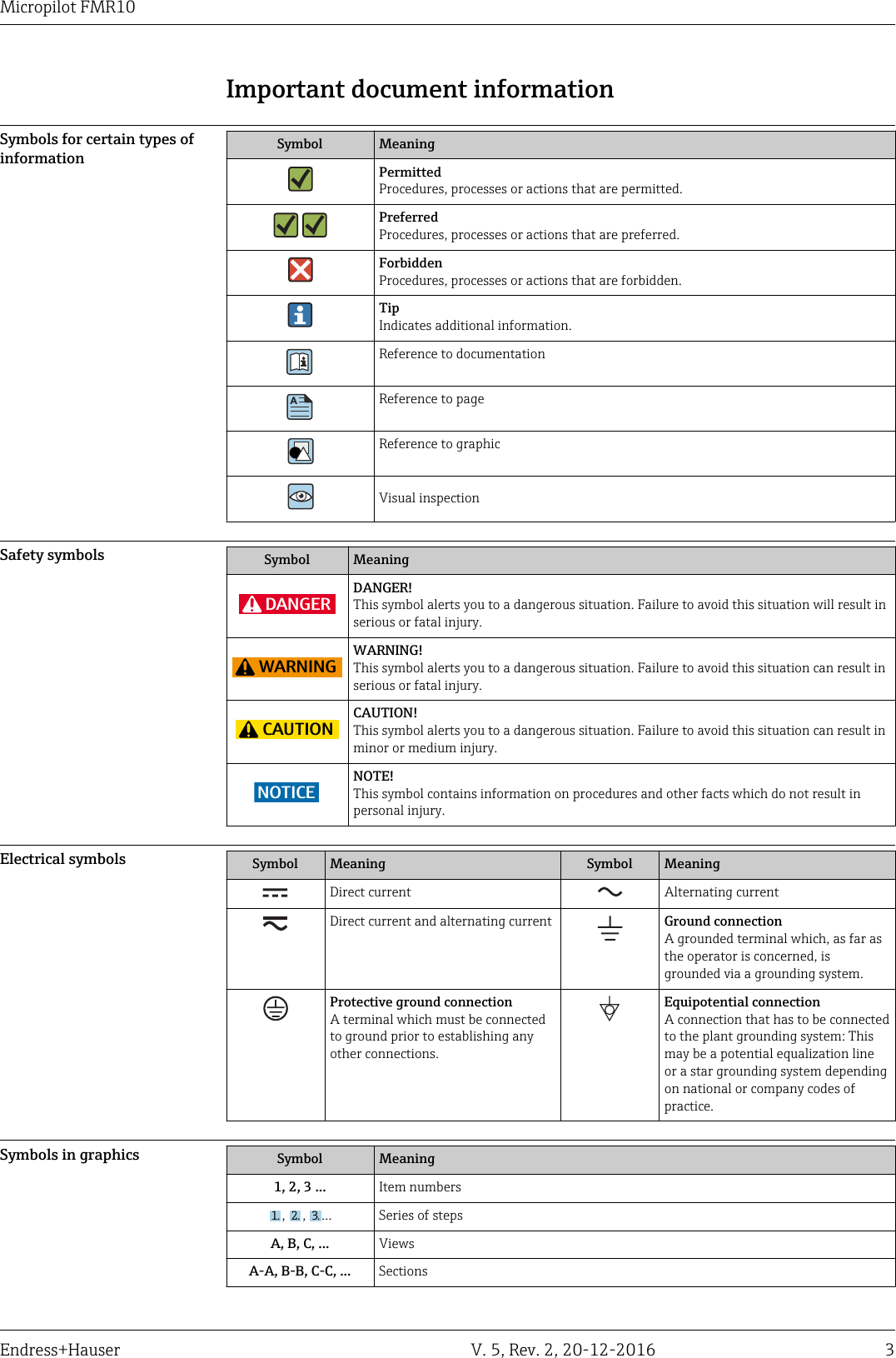
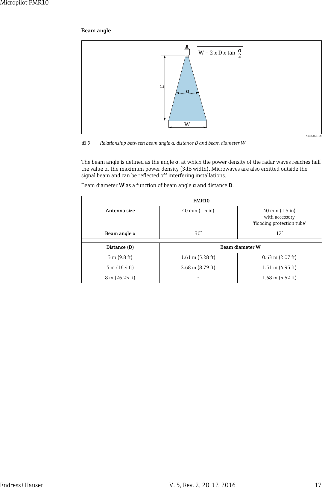
D[mm (in)]5 (0.2)10 (0.39)-20 (0.79)20 (0.79)-5 (-0.2)-10 (-0.39)R0,1 (0.33)R A0029048-EN 4 Maximum measured error in near-range applications∆ Maximum measured errorR Reference point of the distance measurementD Distance from reference point of antennaMeasured value resolution Dead band as per EN61298-2:• Digital: 1 mm (0.04 in)• Analog: 4 µAResponse time The response time can be configured. The following step response times (as per DIN EN 61298-2) 1)apply if the damping is switched off:Tank height Sampling rate Response time< 5 m (16 ft) 1 s-1 < 3 s1) According to DIN EN 61298-2 the step response time is the time which passes after a sudden change of the input signal until the output signalassumes 90% of the steady-state value for the first time.](https://usermanual.wiki/Endress-and-Hauser-and-Co/FMR2XKF.User-Manual-FRM10/User-Guide-3254519-Page-12.png)
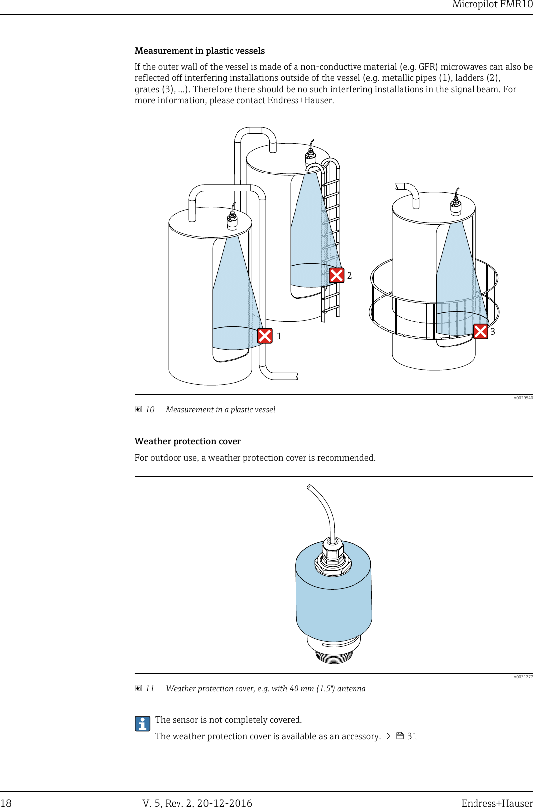
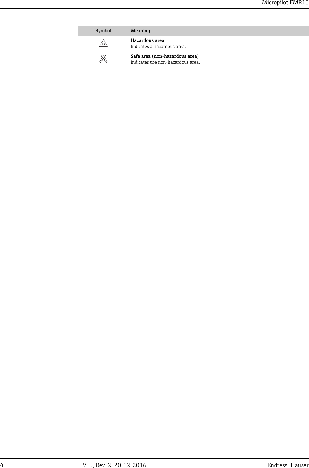
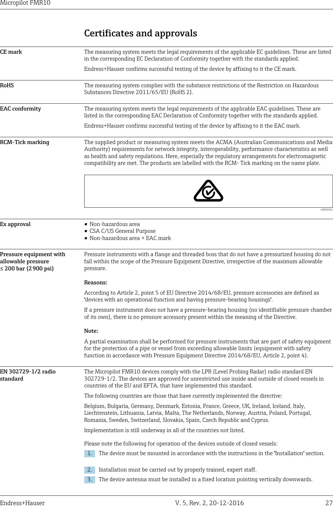
![Micropilot FMR1022 V. 5, Rev. 2, 20-12-2016 Endress+HauserProcessProcess temperature, processpressureFMR10p-40 +60 ( 40)+10 ( )+32Tp[ °F ]°C ( )-1( )-14.50[bar ](psi)3 (43.5) A0030443-EN 15 FMR10: Permitted range for process temperature and process pressureFeature 100 "Process connection" Process temperature range Process pressure range• VEE: Thread ASME MNPT1-1/2;PVDF• WFE: Thread ISO228 G1-1/2; PVDF–40 to +60 °C (–40 to +140 °F) prel = –1 to 3 bar (–14.5 to 43.5 psi)pabs < 4 bar (58 psi)Dielectric constant For liquidsεr ≥ 4For dielectric constants (DC values) of many media commonly used in various industries referto:• the Endress+Hauser DC manual (CP01076F)• the Endress+Hauser "DC Values App" (available for Android and iOS)](https://usermanual.wiki/Endress-and-Hauser-and-Co/FMR2XKF.User-Manual-FRM10/User-Guide-3254519-Page-22.png)

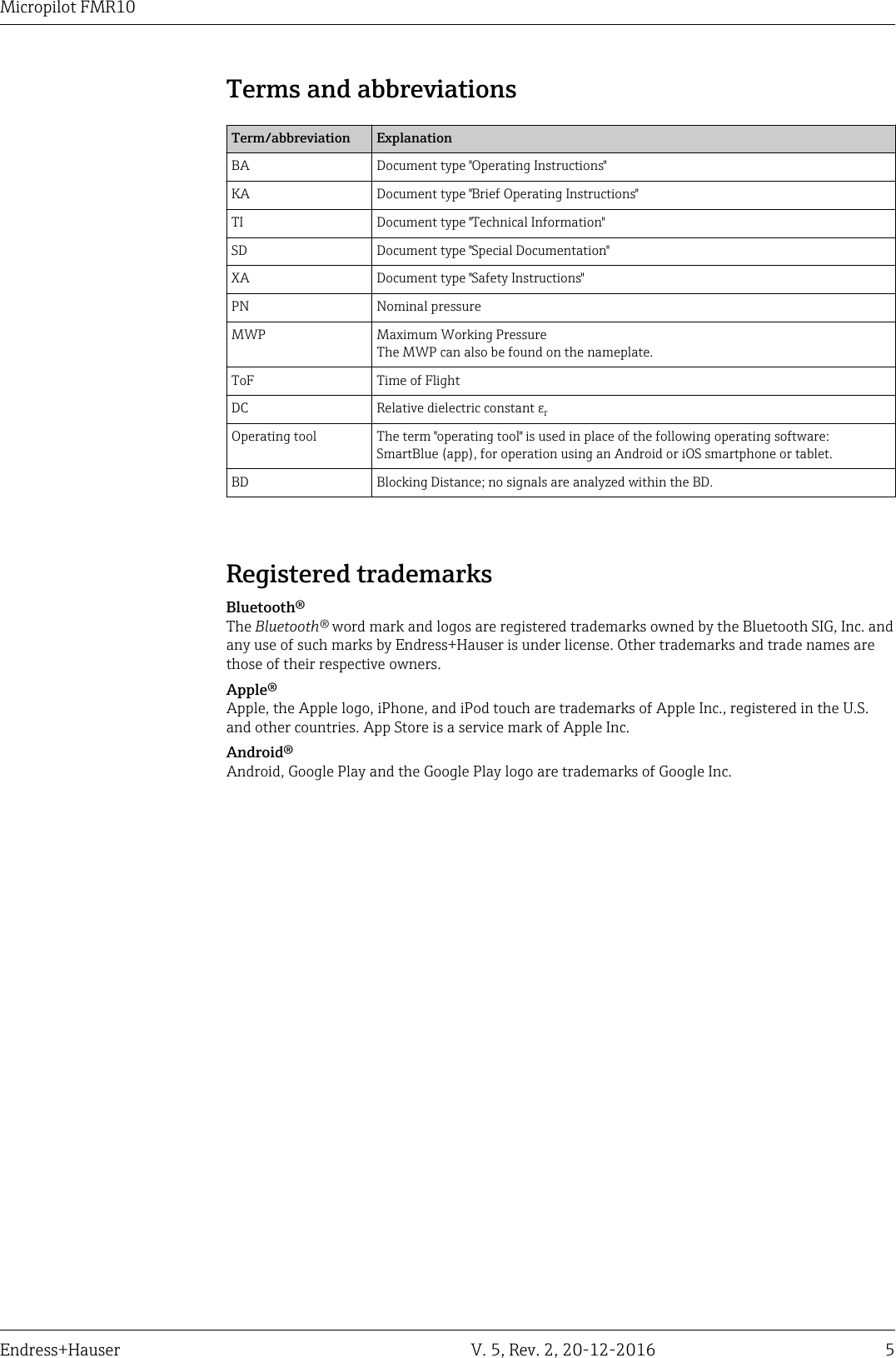
![Micropilot FMR1028 V. 5, Rev. 2, 20-12-2016 Endress+Hauser4. The installation site must be located at a distance of 4 km from the astronomy stations listedbelow or otherwise approval must be provided by the relevant authority. If the device isinstalled at a distance of 4 to 40 km from one of the listed stations, it must not be installed at aheight of more than 15 m (49 ft) above the ground.Astronomy stationsCountry Name of the station Latitude LongitudeGermany Effelsberg 50°31'32" North 06°53'00" EastFinland Metsähovi 60°13'04" North 24°23'37" EastTuorla 60°24'56" North 24°26'31" EastFrance Plateau de Bure 44°38'01" North 05°54'26" EastFloirac 44°50'10" North 00°31'37" WestGreat Britain Cambridge 52°09'59" North 00°02'20" EastDamhall 53°09'22" North 02°32'03" WestJodrell Bank 53°14'10" North 02°18'26" WestKnockin 52°47'24" North 02°59'45" WestPickmere 53°17'18" North 02°26'38" WestItaly Medicina 44°31'14" North 11°38'49" EastNoto 36°52'34" North 14°59'21" EastSardinia 39°29'50" North 09°14'40" EastPoland Fort Skala Krakow 50°03'18" North 19°49'36" EastRussia Dmitrov 56°26'00" North 37°27'00" EastKalyazin 57°13'22" North 37°54'01" EastPushchino 54°49'00" North 37°40'00" EastZelenchukskaya 43°49'53" North 41°35'32" EastSweden Onsala 57°23'45" North 11°55'35" EastSwitzerland Bleien 47°20'26" North 08°06'44" EastSpain Yebes 40°31'27" North 03°05'22" WestRobledo 40°25'38" North 04°14'57" WestHungary Penc 47°47'22" North 19°16'53" EastAs a general rule, the requirements outlined in EN 302729-1/2 must be observed.FCC / Industry Canada This device complies with Part 15 of the FCC Rules [and with Industry Canada licence-exempt RSSstandard(s)]. Operation is subject to the following two conditions: (1) this device may not causeharmful interference, and (2) this device must accept any interference received, includinginterference that may cause undesired operation.Le présent appareil est conforme aux CNR d'Industrie Canada applicables aux appareils radio exemptsde licence. L'exploitation est autorisée aux deux conditions suivantes: (1) l'appareil ne doit pas produirede brouillage, et (2) l'utilisateur de l'appareil doit accepter tout brouillage radioélectrique subi, même sile brouillage est susceptible d'en compromettre le fonctionnement.](https://usermanual.wiki/Endress-and-Hauser-and-Co/FMR2XKF.User-Manual-FRM10/User-Guide-3254519-Page-28.png)
![Micropilot FMR10Endress+Hauser V. 5, Rev. 2, 20-12-2016 29[Any] Changes or modifications made to this equipment not expressly approved by Endress+Hausermay void the FCC authorization to operate this equipment.This equipment has been tested and found to comply with the limits for a Class B digital device,pursuant to Part 15 of the FCC Rules. These limits are designed to provide reasonableprotection against harmful interference in a residential installation. This equipment generates,uses and can radiate radio frequency energy and, if not installed and used in accordance withthe instructions, may cause harmful interference to radio communications. However, there is noguarantee that interference will not occur in a particular installation. If this equipment doescause harmful interference to radio or television reception, which can be determined by turningthe equipment off and on, the user is encouraged to try to correct the interference by one ormore of the following measures:• Reorient or relocate the receiving antenna• Increase the separation between the equipment and receiver• Connect the equipment into an outlet on a circuit different from that to which the receiver isconnected• Consult the dealer or an experienced radio/TV technician for help• The installation of the LPR/TLPR device shall be done by trained installers, in strictcompliance with the manufacturer’s instructions.• The use of this device is on a “no-interference, no-protection” basis. That is, the user shallaccept operations of high-powered radar in the same frequency band which may interferewith or damage this device. However, devices found to interfere with primary licensingoperations will be required to be removed at the user’s expense.• Only for usage without the accessory “flooding protection tube”, i.e. NOT in the free-field:This device shall be installed and operated in a completely enclosed container to prevent RFemissions, which can otherwise interfere with aeronautical navigation.](https://usermanual.wiki/Endress-and-Hauser-and-Co/FMR2XKF.User-Manual-FRM10/User-Guide-3254519-Page-29.png)