Future Systems FGT100 VPN GATEWAY User Manual FCC040401
Future Systems, Inc. VPN GATEWAY FCC040401
UserManual.wiki
>
Future Systems
>
FGT100 User Manual
>
Users Manual 1
Contents
1.
Users Manual 1
2.
Users Manual 2
Users Manual 1
Navigation menu
Upload a User Manual
Namespaces
Wiki Guide
HTML
PDF
Info
Views
User Manual
Discussion / Help
Navigation
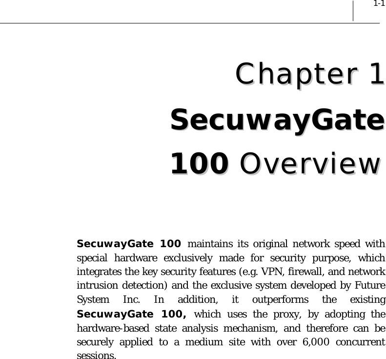
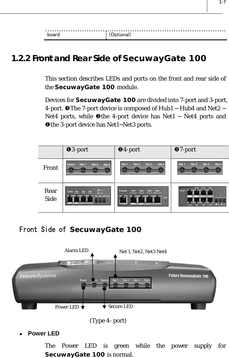
![1-6 Chapter 1 SecuwayGate 2000 Overview 1.2 SecuwayGate 100 System Specifications 1.2.1 Hardware Specifications The table below gives the hardware specifications of Secuway Gate 100. CPU Architecture IBM PPC Main Memory SDRAM 32 MB(Upgradable up to 128MB) ROM Flash ROM type 16MB Spec. IEEE/ANSI 802.3 (CSMA/CD) Speed 10/100Mbps Full duplex, Interface TCP/IP, 10/100BASE-TX, RJ-45 LAN Port wType 3-port(Private, Multi, Public) wType 4 –port(Private, Multi, Public, Black Zone) wType 7 –port(Private<4ea>, Multi, Public, Black Zone) Speed 38,400 bps Console port Interface RJ-45 (RS-232C) LED wType 3-port(Power, Alarm, Secure, Admin, Net1, Net2, Net3) wType 4-port(Power, Alarm, Secure, Net1, Net2, Net3, Net4) wType 7-port(Power, Alarm, Secure, Hub, Net1, Net2, Net3) Real Time Clock Built-in Buzzer Built-in Battery Built-in Dimension 294X215X68[mm] (HeightxWidthxDepth) External 85~264V Internal DC 3.3V (15A MAX) DC 5V (2A MAX) Power Power usage 15 W (typical) Physical security Tamperproof (Only Type 4-port) Emergency Erase Switch Support Encryption accelerator Equipped with a specialized encryption ASIC chip](https://usermanual.wiki/Future-Systems/FGT100.Users-Manual-1/User-Guide-411286-Page-22.png)
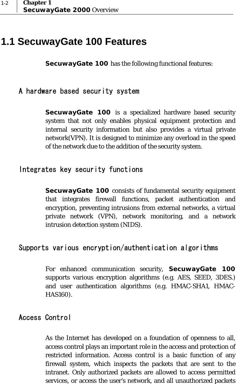
![2-14 Chapter 1 SecuwayGate 2000 Overview 4. When the file is completely imported to SecuwayGate 100, enter the password and type [y]. SecuwayGate 100 will begin initial setup process and then automatically restart.](https://usermanual.wiki/Future-Systems/FGT100.Users-Manual-1/User-Guide-411286-Page-42.png)