GasSecure AS GS01AA Wireless gas detector User Manual GasSecure GS01 Hardware Manual
GasSecure AS Wireless gas detector GasSecure GS01 Hardware Manual
UserManual.wiki
>
GasSecure AS
>
GS01AA User Manual
>
Users Manual
Contents
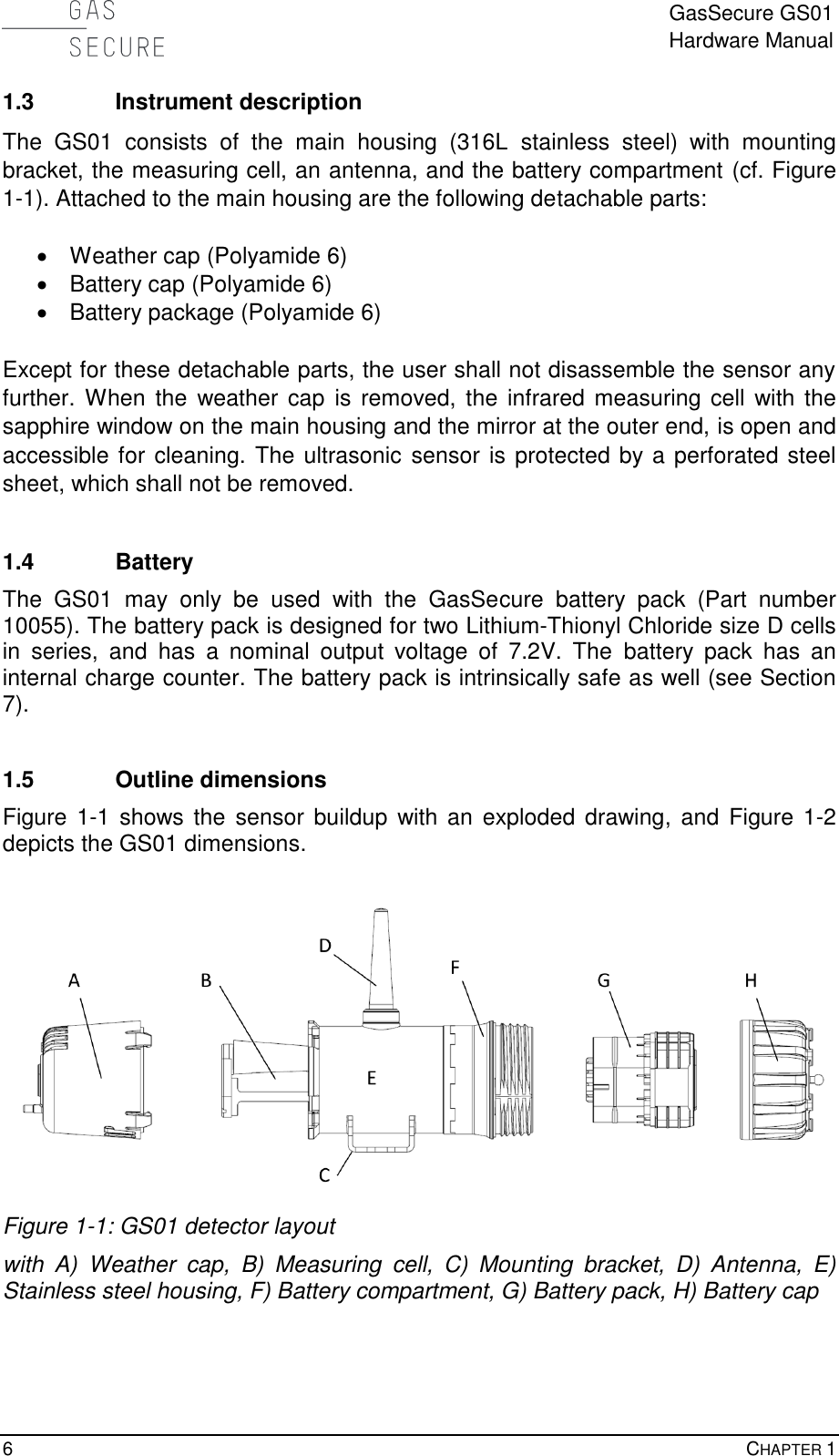
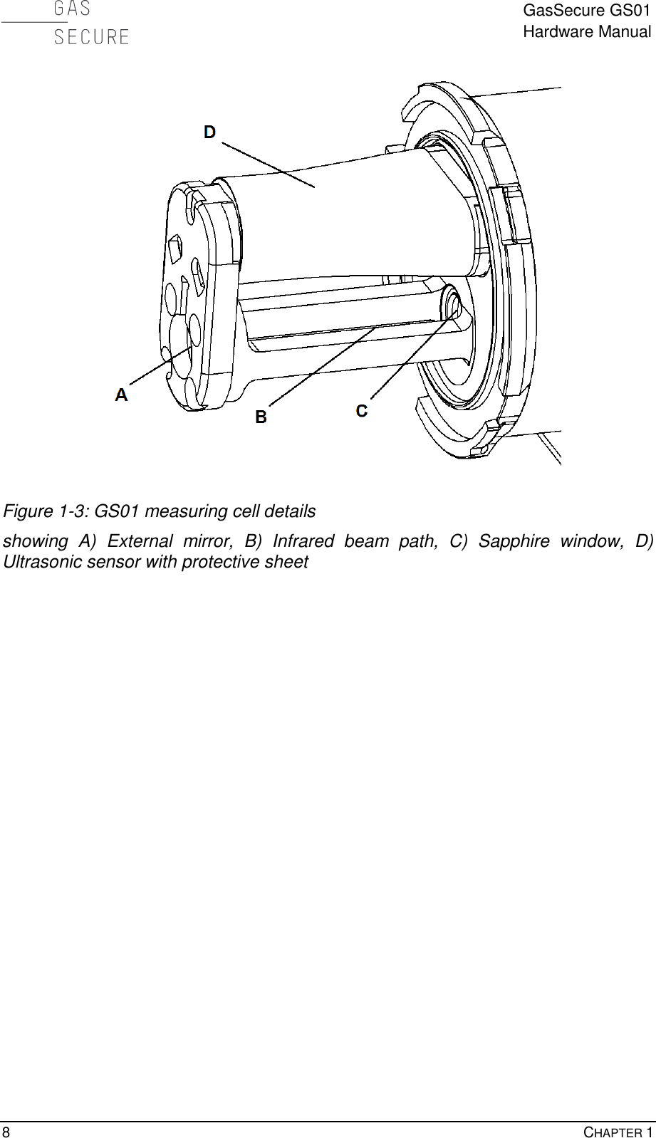
1.
Users Manual
2.
user manual
Users Manual
Navigation menu
Upload a User Manual
Namespaces
Wiki Guide
HTML
PDF
Info
Views
User Manual
Discussion / Help
Navigation
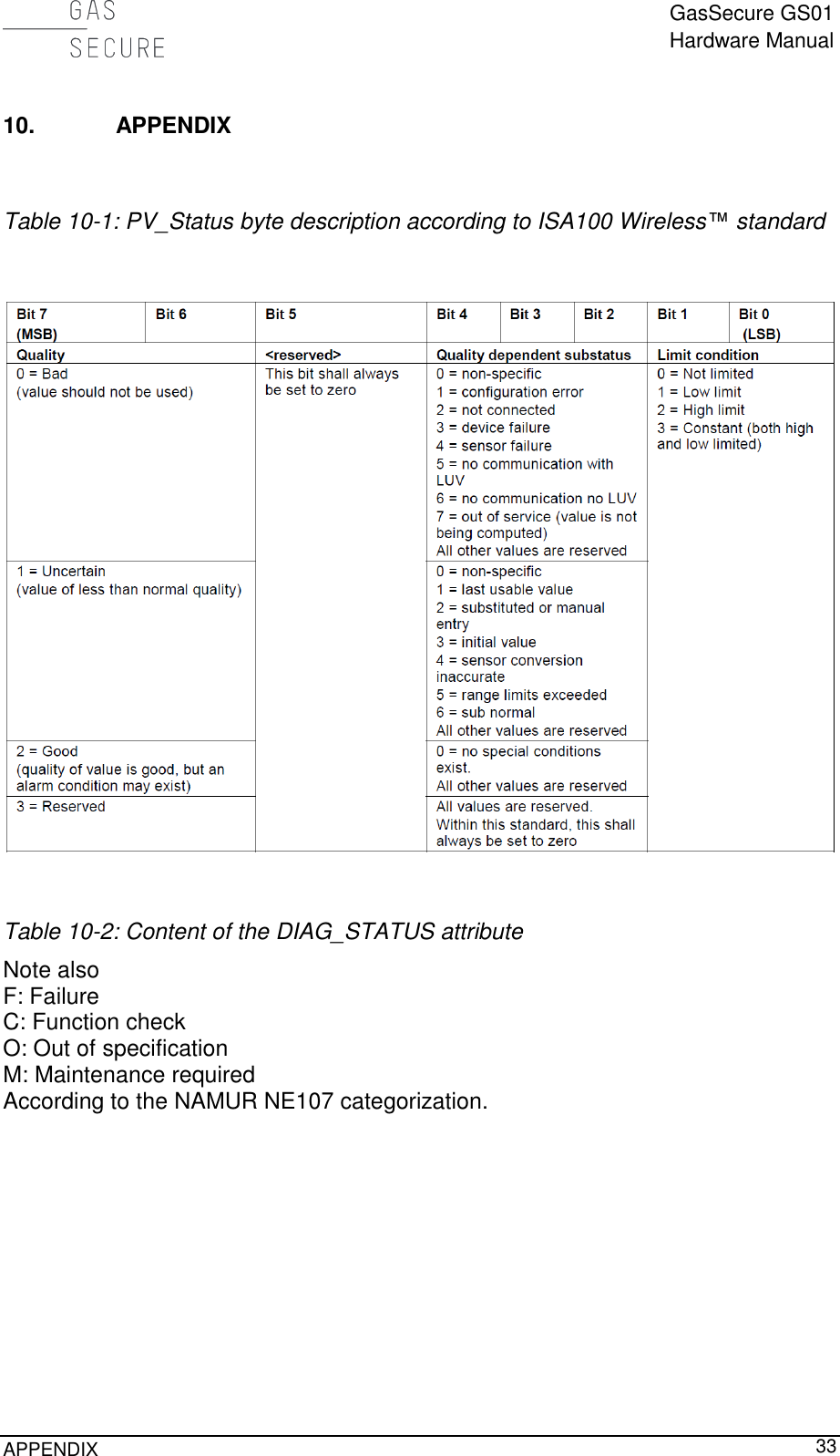
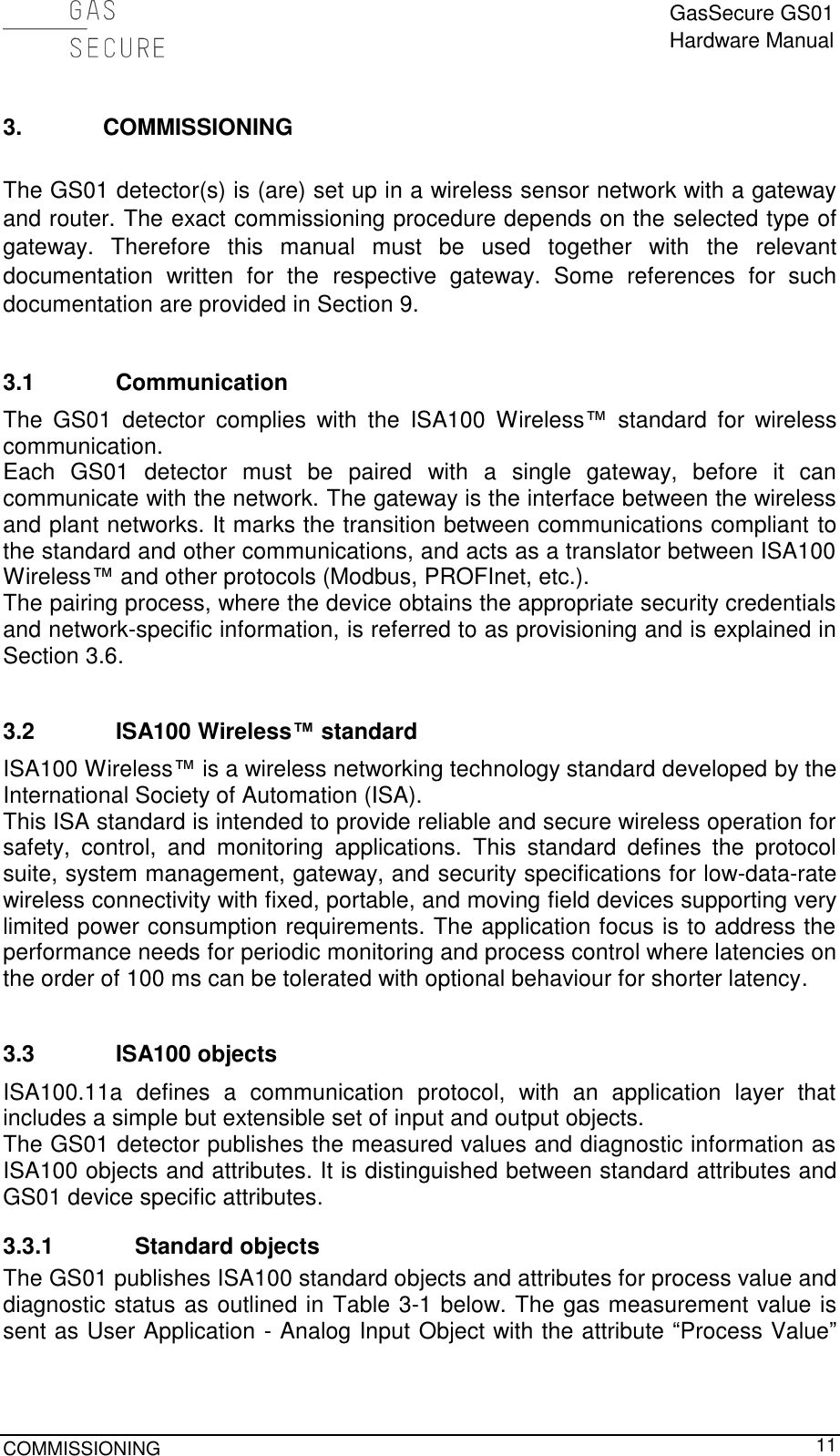
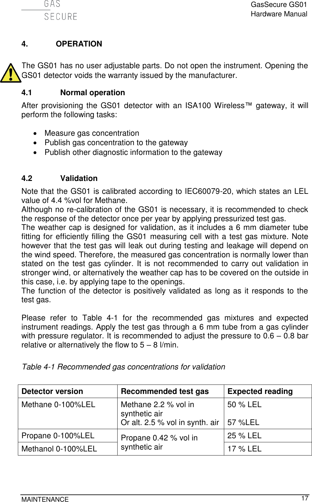
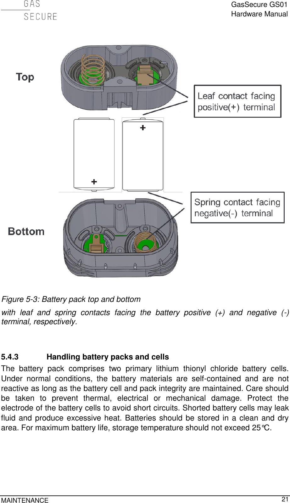
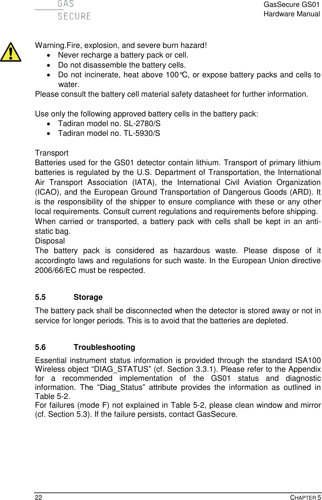
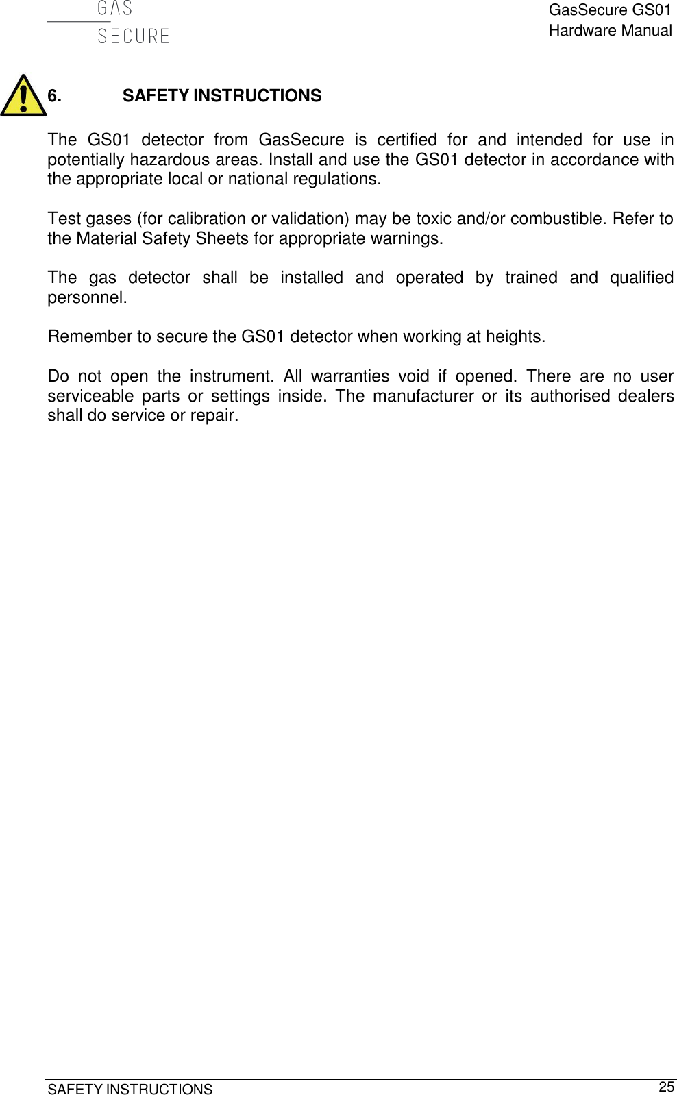
![GasSecure GS01 Hardware Manual IV FIGURES FIGURE 1-1: GS01 DETECTOR LAYOUT................................................................................................................ 6 FIGURE 1-2: GS01 DETECTOR WITH DIMENSIONS IN [MM] ................................................................................... 7 FIGURE 1-3: GS01 MEASURING CELL DETAILS ..................................................................................................... 8 FIGURE 2-1: CORRECT POSITION OF THE WEATHER CAP AND LOCATION OF EARTH POINT. ................................. 10 FIGURE 3-1: GS PROVISIONING TOOL ............................................................................................................... 15 FIGURE 5-1: BATTERY PACK WARNING LABEL ................................................................................................... 20 FIGURE 5-2: BATTERY PACK BOTTOM VIEW ...................................................................................................... 20 FIGURE 5-3: BATTERY PACK TOP AND BOTTOM ................................................................................................. 21 FIGURE 7-1: GS01 PRODUCT IDENTIFICATION PLATE ......................................................................................... 27 FIGURE 7-2: FCC COMPLIANCE LABEL .............................................................................................................. 28 FIGURE 7-3: BATTERY PACK IDENTIFICATION LABEL ......................................................................................... 29 TABLES TABLE 3-1 ISA100 OBJECTS ............................................................................................................................. 12 TABLE 3-2 PV GAS MEASUREMENT DATA INTEGRITY ....................................................................................... 13 TABLE 4-1 RECOMMENDED GAS CONCENTRATIONS FOR VALIDATION ............................................................... 17 TABLE 5-1: IMPORTANT SPARE PARTS FOR THE GS01 ....................................................................................... 18 TABLE 5-2: STATUS MESSAGES RETRIEVED FROM THE DIAG_STATUS ATTRIBUTE ............................................ 23 TABLE 7-1: LIST OF APPLICABLE STANDARDS FOR THE GS01 ............................................................................ 26 TABLE 8-1: PERFORMANCE CHARACTERISTICS FOR THE GS01.......................................................................... 30 TABLE 8-2: LEL VALUES IN [% VOL] ACCORDING TO IEC60079-20. ................................................................ 31 TABLE 8-3 CROSS SENSITIVITIES FOR A GS01 METHANE DETECTOR. ............................................................... 31 TABLE 8-4 CROSS SENSITIVITIES FOR A GS01 PROPANE DETECTOR. ................................................................ 31 TABLE 8-5: CROSS SENSITIVITIES FOR A GS01 METHANOL DETECTOR. ............................................................. 31 TABLE 10-1: PV_STATUS BYTE DESCRIPTION ACCORDING TO ISA100 WIRELESS™ STANDARD....................... 33 TABLE 10-2: CONTENT OF THE DIAG_STATUS ATTRIBUTE ............................................................................ 33](https://usermanual.wiki/GasSecure-AS/GS01AA.Users-Manual/User-Guide-2655758-Page-5.png)
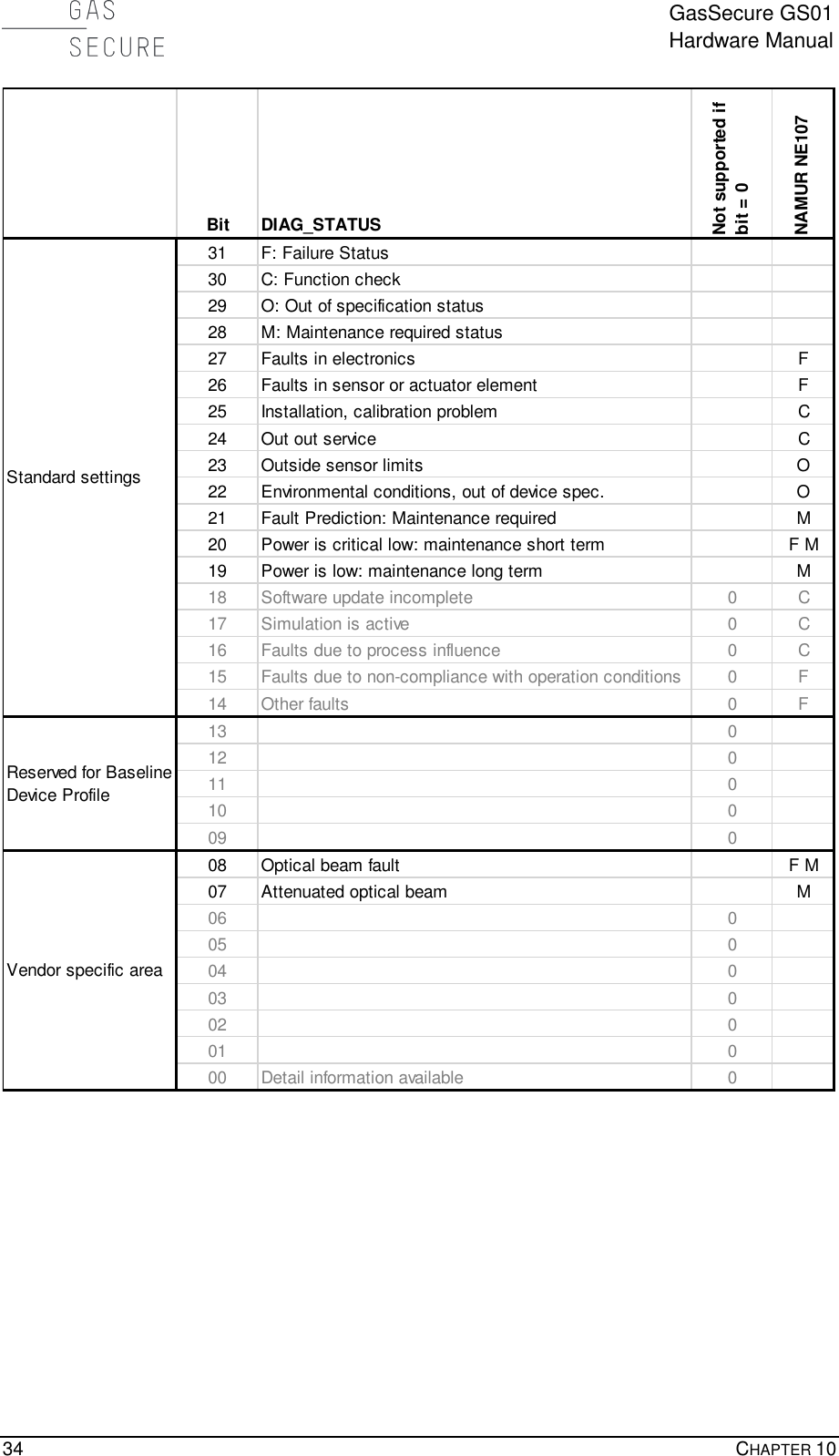
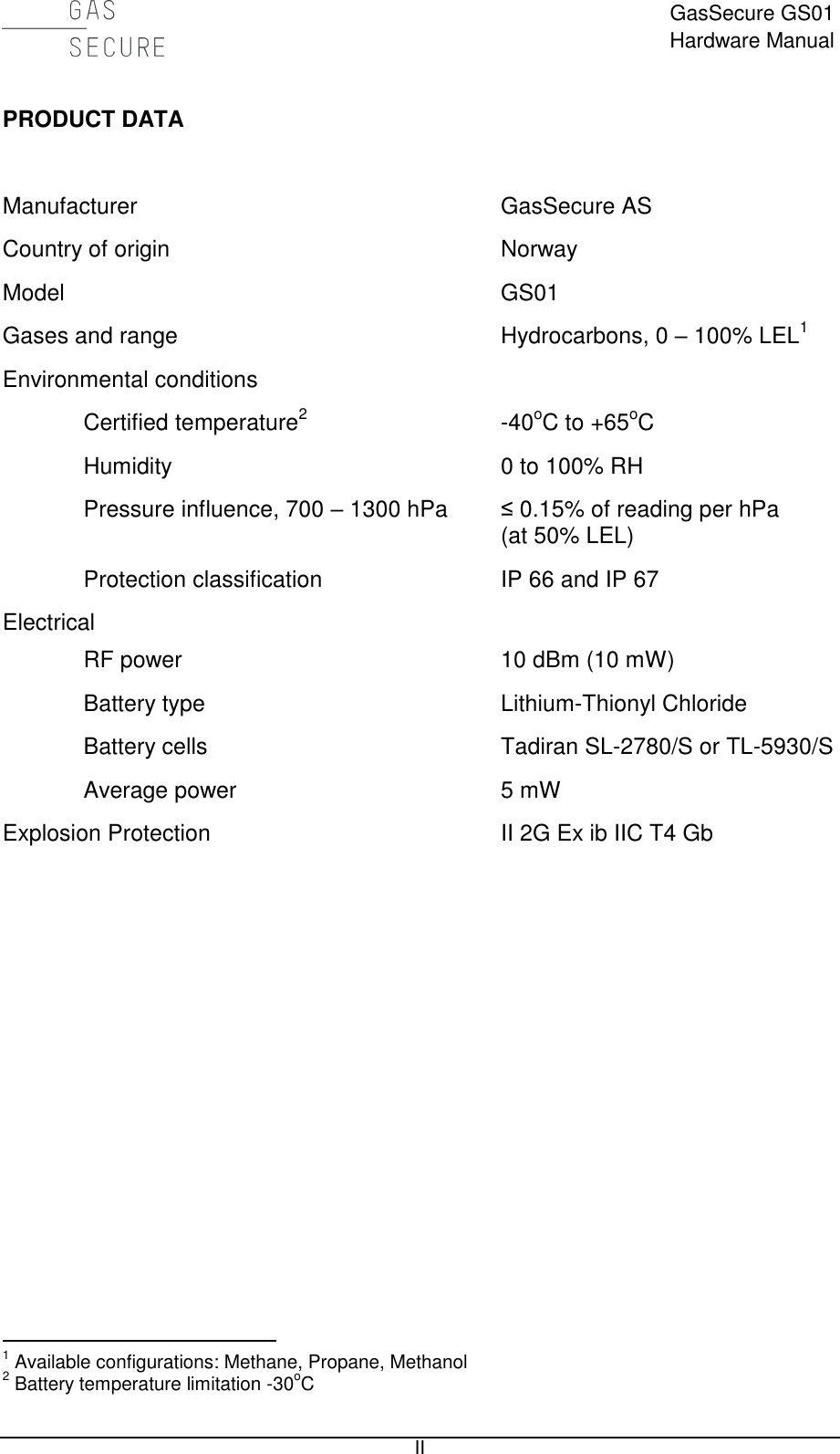
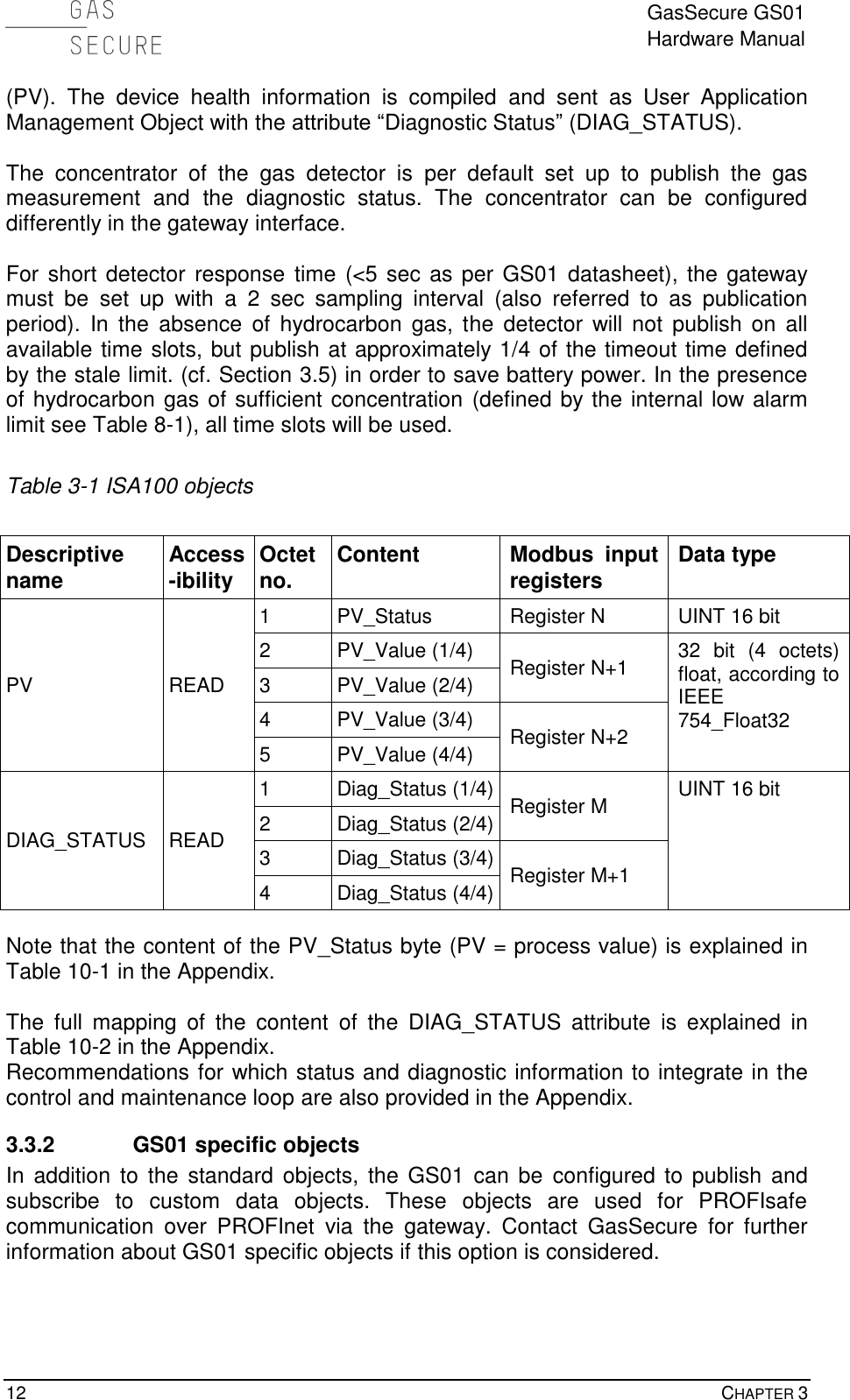
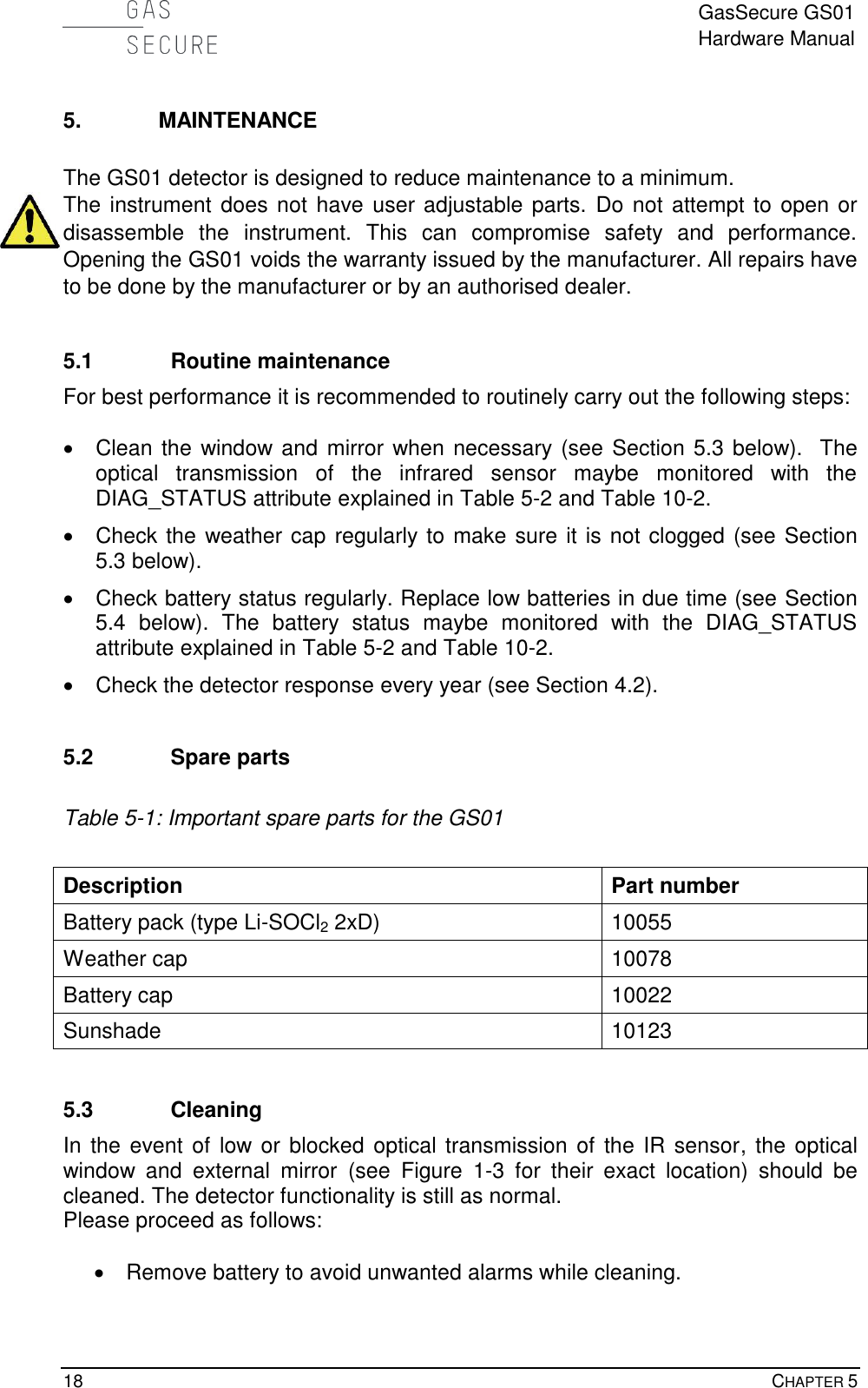
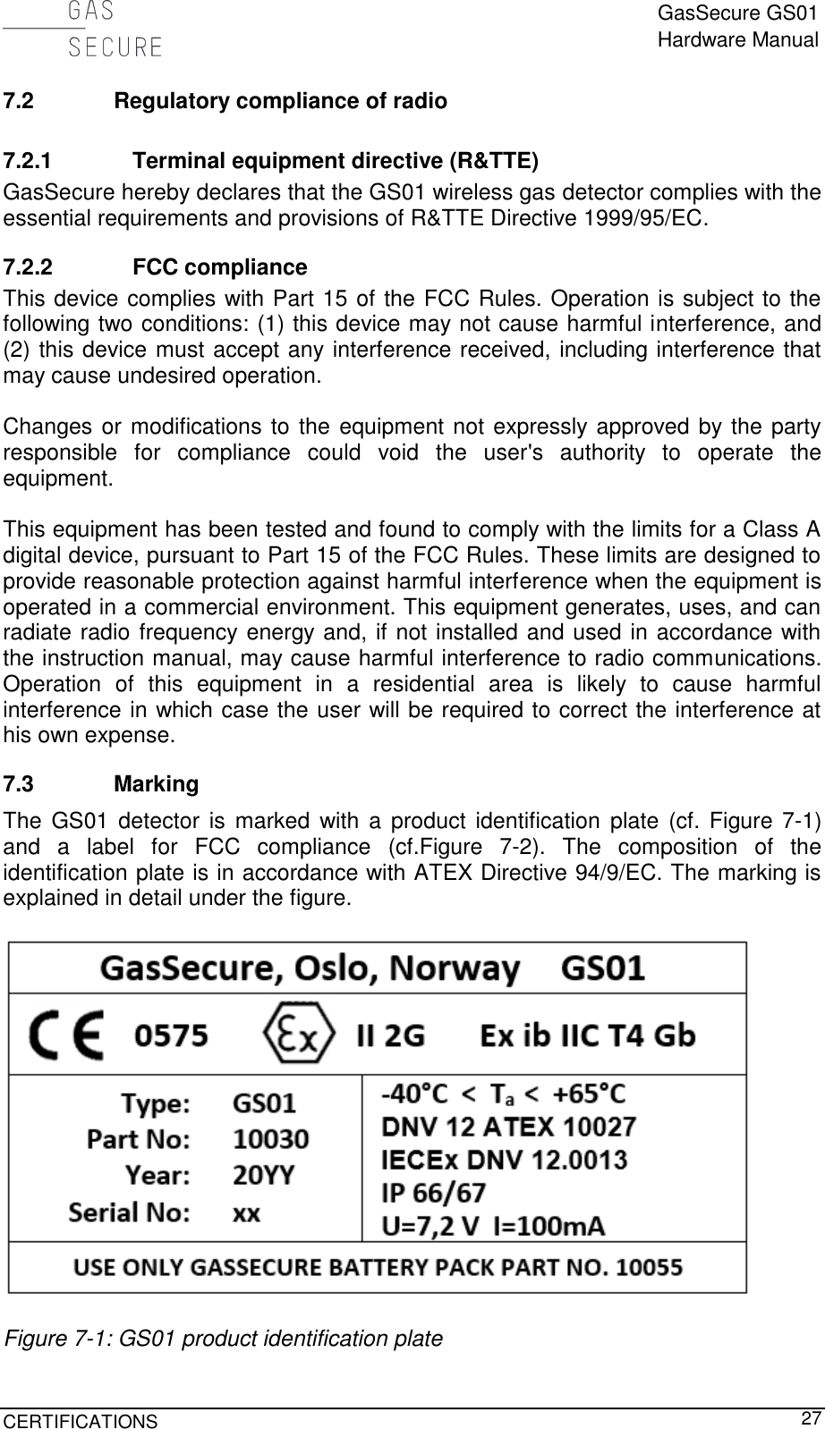
![GasSecure GS01 Hardware Manual DESCRIPTION 7 Figure 1-2: GS01 detector with dimensions in [mm]](https://usermanual.wiki/GasSecure-AS/GS01AA.Users-Manual/User-Guide-2655758-Page-8.png)
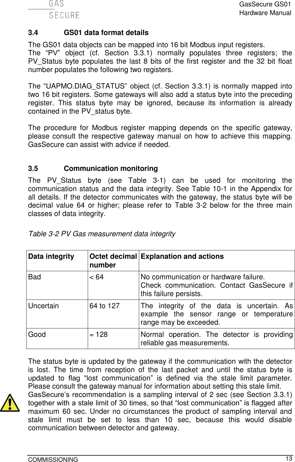
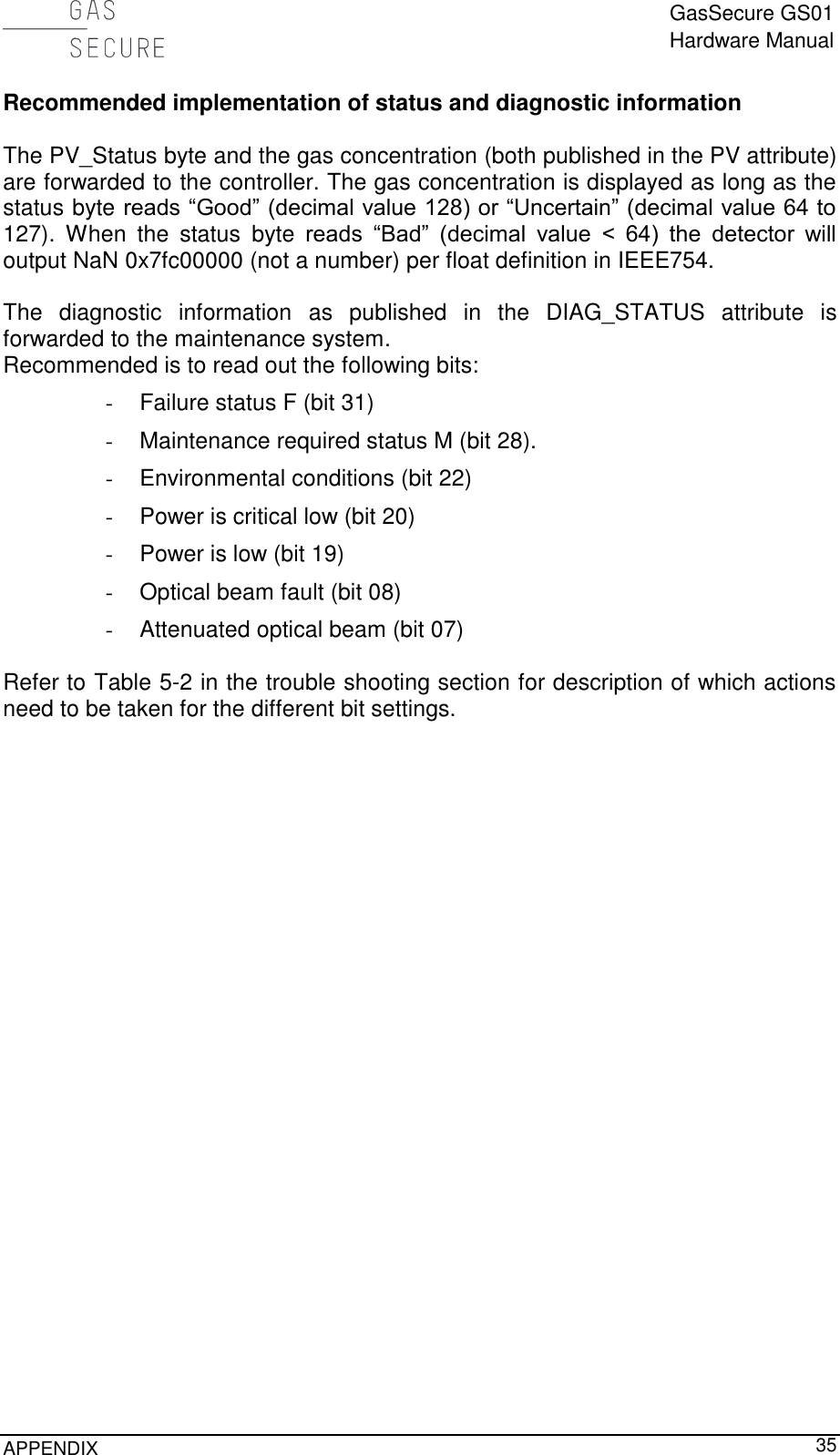
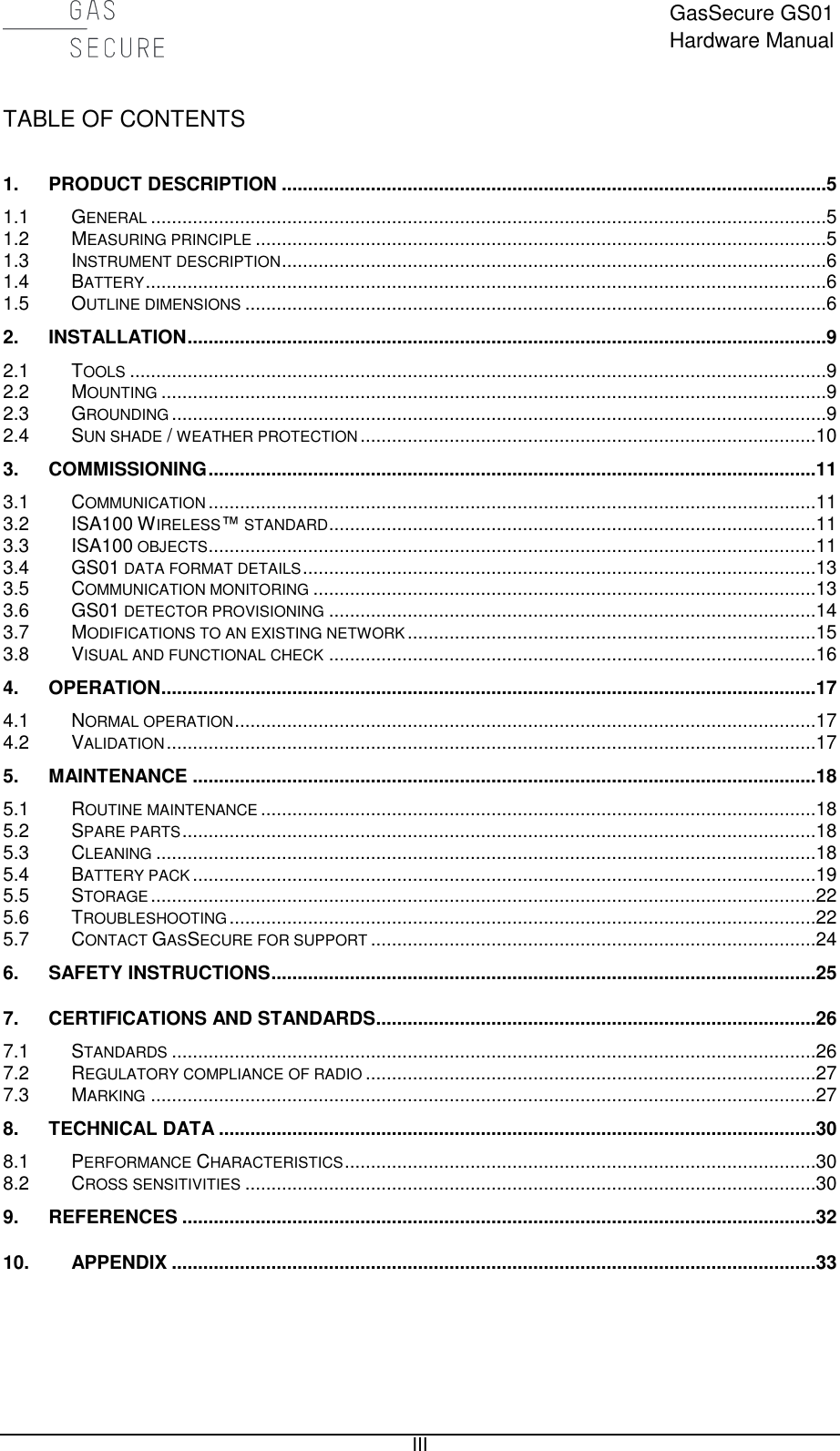
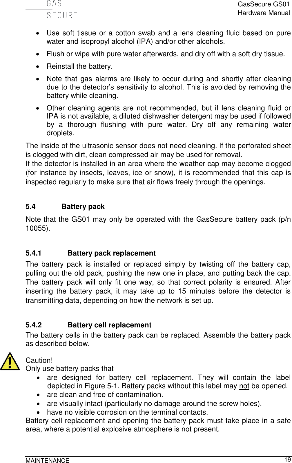
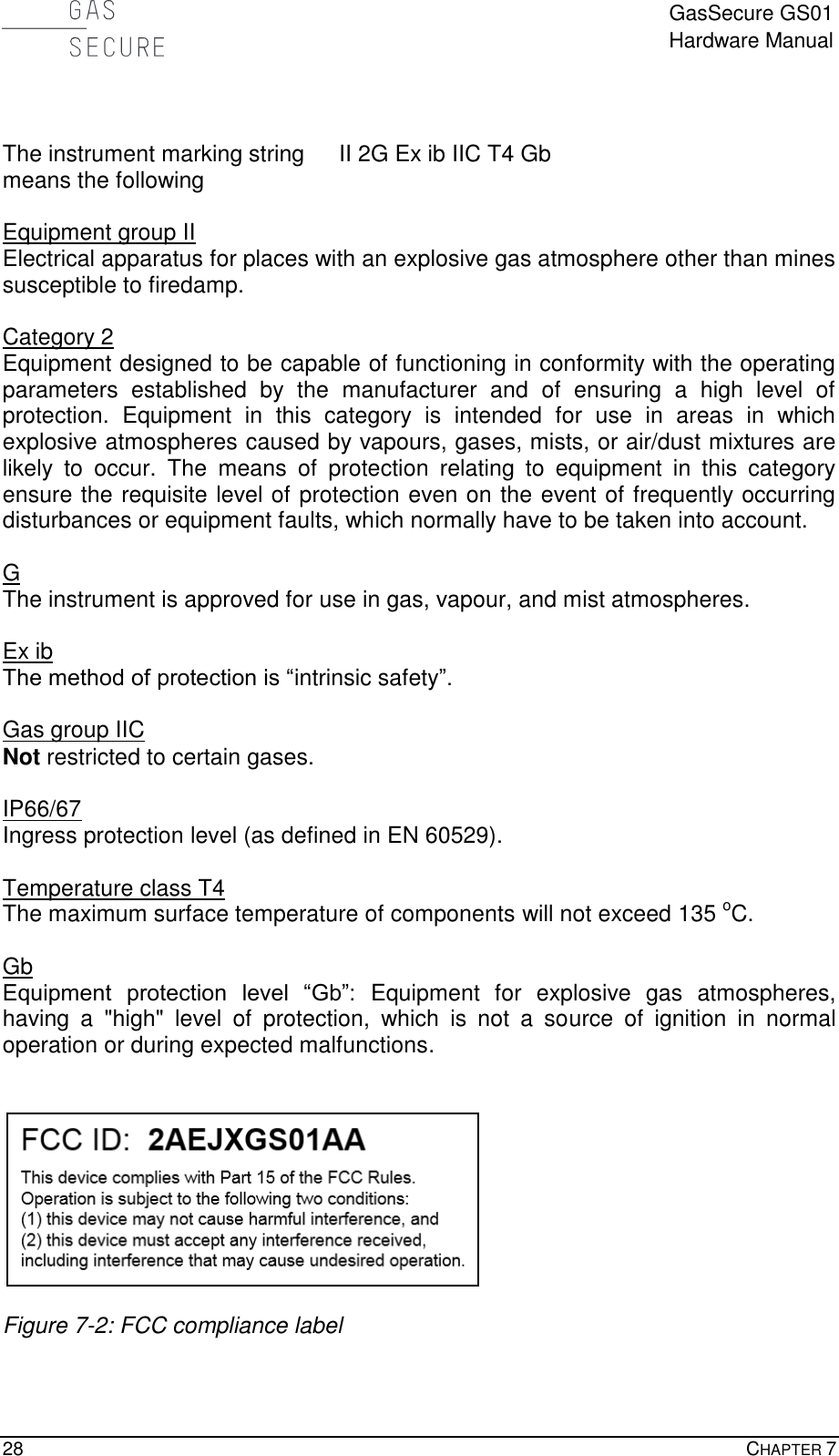
![GasSecure GS01 Hardware Manual 14 CHAPTER 3 Note that the timeout, as defined by the stale limit, can be checked by removing the battery and monitoring the time until the PV_Status byte is updated. 3.6 GS01 detector provisioning All GS01 detectors have to be provisioned so that they will join the correct network. Provisioning the GS01 requires the following: • An USB serial adapter interface to GS01 together with GS Provisioning Tool software (both accessories from GasSecure) • The network (or subnet) ID of the gateway or backbone router This procedure can be carried out with an unprovisioned GS01 or with a GS01 that earlier has been provisioned to another gateway. 3.6.1 Yokogawa gateways a) Connect the GS01 to a PC with the GS Provisioning Tool installed using the USB serial adapter interface. Allow 20 sec. for the booting of the device. b) Run the GS Provisioning Tool and select the correct COM port. Press the “Connect” button and verify that the device info is displayed, cf. Figure 3-1. c) Enter the required network ID (make sure the correct number format is selected: Decimal, Hex, Octal or Binary) and device tag, cf. Figure 3-1. d) Verify that “randomize join key” is selected and specify the destination folder for the YPIF file. This file must be uploaded to the gateway (explained in reference [RD 4]) to enable communication. Press the “do provisioning” button. Verify that the “Provisioning is done!” message is displayed in the command window. e) Close and exit the GS Provisioning Tool and disconnect the GS01 detector from the PC. f) Power up the GS01 by inserting the battery pack. g) The GS01 device should join the network within 5-20 minutes, if it is within radio distance to the gateway and the gateway is set up properly (refer to reference [RD 4]).](https://usermanual.wiki/GasSecure-AS/GS01AA.Users-Manual/User-Guide-2655758-Page-15.png)
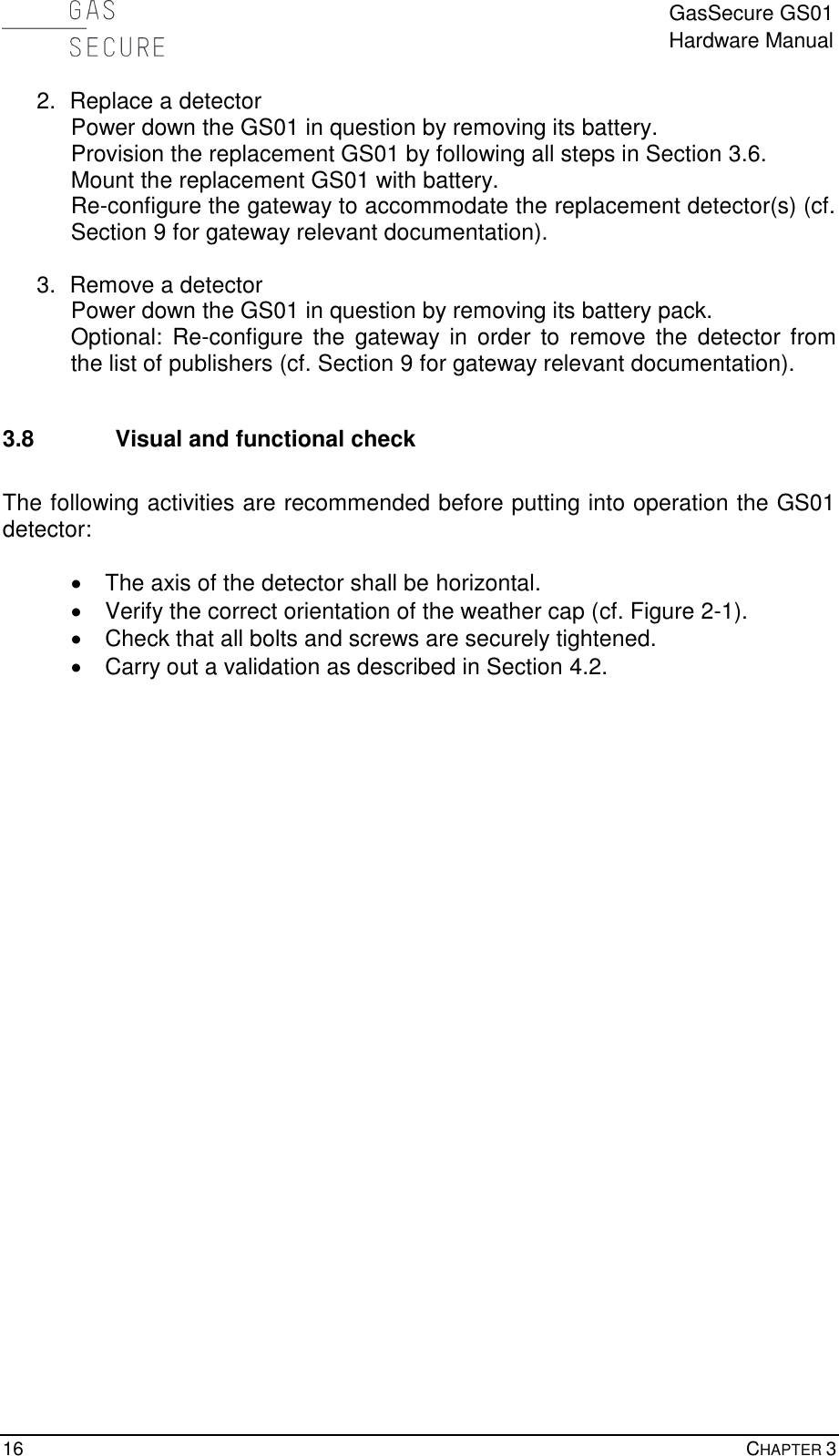
![GasSecure GS01 Hardware Manual COMMISSIONING 15 Figure 3-1: GS Provisioning Tool 3.6.2 Other ISA100 Wireless gateways a) Connect the GS01 to a PC with the GS Provisioning Tool installed using the USB serial adapter interface. Allow 20 sec. for the booting of the device. b) Run the GS Provisioning Tool and select the correct COM port. Press the “Connect” button and verify that the device info is displayed. c) Press the “Reset to Factory Default” button. d) Close and exit the GS Provisioning Tool and disconnect the GS01 detector from the PC. e) Power up the GS01 by inserting the battery pack. f) The GS01 can now be provisioned over the air (OTA) using either special field tools or the field wireless access points. Refer to references [RD6] or [RD 8] for possible solutions from different vendors. g) The GS01 device should join the network within 5-20 minutes, if it is within radio distance to the gateway and the gateway is set up properly. 3.7 Modifications to an existing network 1. Add a detector Provision the GS01 as described in Section 3.6. Mount the GS01 with battery. Re-configure the gateway to accommodate the additional detector(s) (cf. Section 9 for gateway relevant documentation).](https://usermanual.wiki/GasSecure-AS/GS01AA.Users-Manual/User-Guide-2655758-Page-16.png)
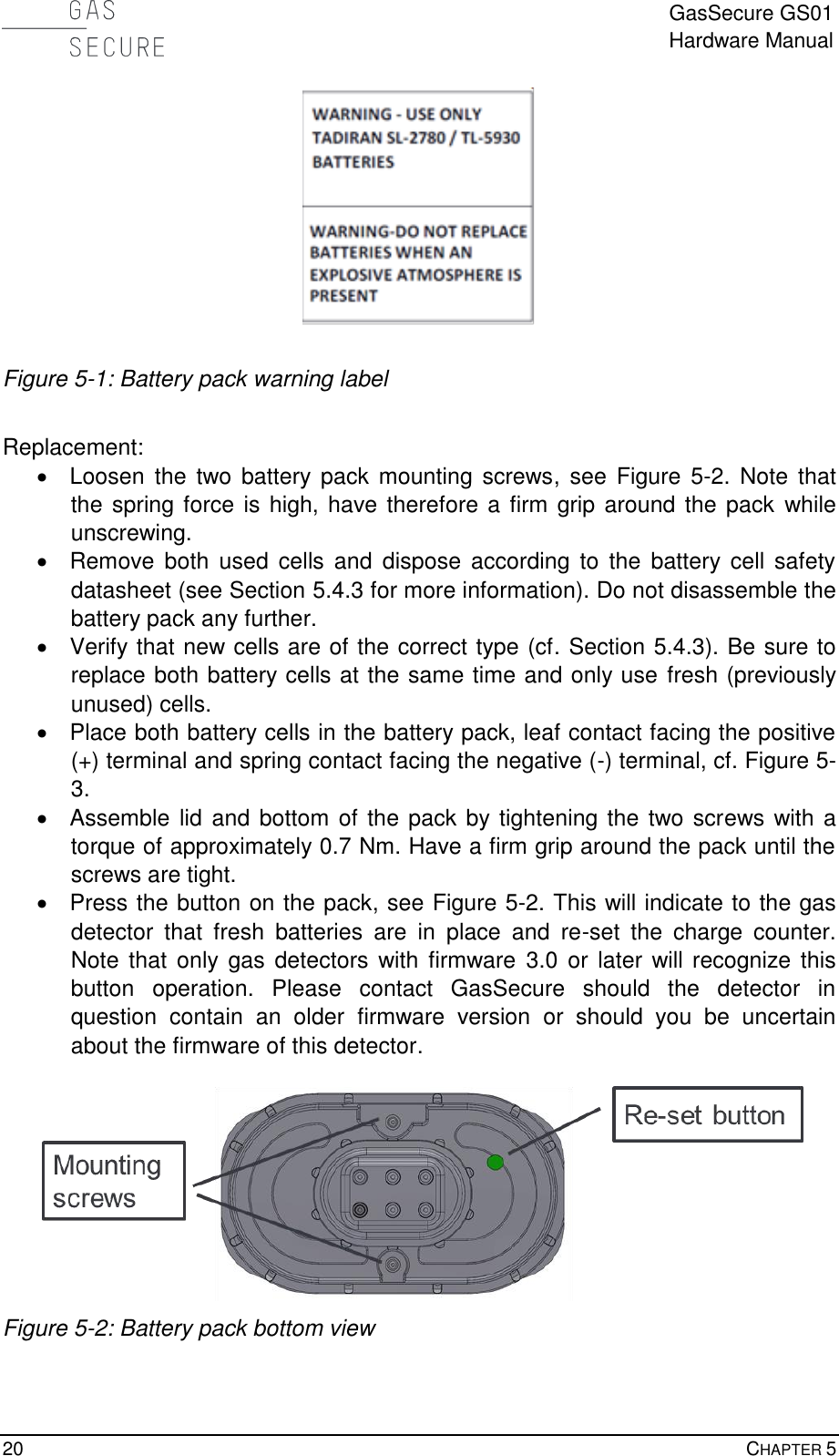

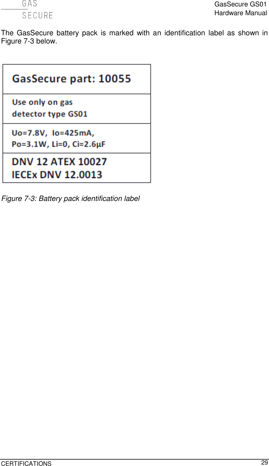
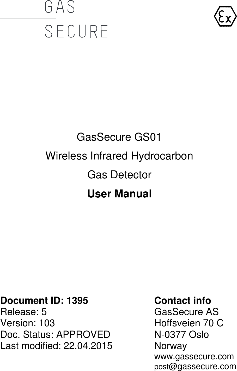
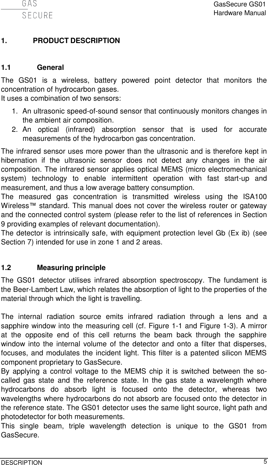
![GasSecure GS01 Hardware Manual TECHNICAL DATA 31 Table 8-2: LEL values in [% vol] according to IEC60079-20. Methane Propane Methanol Ethanol Ethylene N-butane Hexane Styrene Benzene 4.4 1.7 6.0 3.1 2.3 1.4 1.0 1.0 1.2 8.2.1 GS01-01A Methane detector Table 8-3 Cross sensitivities for a GS01 Methane detector. Reading Propane Methanol Ethanol Ethylene N-butane Hexane Styrene Benzene 10 6 4 6 27 7 7 16 27 20 9 7 10 42 11 11 25 44 30 11 8 13 54 14 14 31 56 40 14 10 15 63 16 17 37 67 50 15 11 17 71 18 19 42 76 75 19 14 21 89 23 24 51 97 100 23 16 25 100 28 29 59 100 8.2.2 GS01-02A Propane detector Table 8-4 Cross sensitivities for a GS01 Propane detector. Reading Methane Methanol Ethanol Ethylene N-butane Hexane Styrene Benzene 10 24 7 11 47 12 12 28 49 20 79 14 22 91 24 25 53 99 30 160 20 32 130 36 39 75 150 40 200 26 42 170 49 53 95 200 50 >200 31 51 200 62 68 110 >200 75 >200 42 72 >200 97 110 150 >200 100 >200 51 91 >200 130 170 180 >200 8.2.3 GS01-03A Methanol detector Table 8-5: Cross sensitivities for a GS01 Methanol detector. Reading Methane Propane Ethanol Ethylene N-butane Hexane Styrene Benzene 10 41 14 15 65 16 17 38 68 20 150 30 32 130 36 38 74 150 30 >200 48 49 190 59 65 110 200 40 >200 70 68 >200 89 100 140 >200 50 >200 97 88 >200 130 170 170 >200 75 >200 200 160 >200 >200 >200 200 >200 100 >200 >200 >200 >200 >200 >200 >200 >200](https://usermanual.wiki/GasSecure-AS/GS01AA.Users-Manual/User-Guide-2655758-Page-32.png)
![GasSecure GS01 Hardware Manual 32 CHAPTER 8 9. REFERENCES [RD 1] Nivis ISA100.11a R2.7 Monitoring Control System User Guide Version: 1.2, Date: March 30, 2012 [RD 2] Nivis VersaRouter 900 Hardware User Guide (VR800 Internal Hardware Rev. C) Version 1.4, Date: Mar. 18, 2010 [RD 3] Yokogawa YFGW410 Field Wireless Management Station user’s manual, IM 01W02D01-01EN [RD 4] Yokogawa YFGW410 Field Wireless Management Station Startup Guide, TI 01W01A56-01EN [RD 5] Yokogawa YFGW510 Field Wireless Access Point user’s manual, IM 01W02E01-01EN [RD 6] Honeywell Wireless Device Manager User's Guide, Release 220, OWDOC-X254-en-220A, October 2013 [RD 7] Honeywell Field Device Access Point User's Guide, Release 220, OWDOC-X256-en-220A, October 2013 [RD 8] Nivis ISA100.11a Field Tool User Manual, Version 2.1, Date: October 17, 2013](https://usermanual.wiki/GasSecure-AS/GS01AA.Users-Manual/User-Guide-2655758-Page-33.png)