Hangzhou Hikvision Digital Technology K1T605EF Face Recognition Terminal User Manual
Hangzhou Hikvision Digital Technology Co., Ltd. Face Recognition Terminal
UserManual.wiki
>
Hangzhou Hikvision Digital Technology
>
K1T605EF User Manual
>
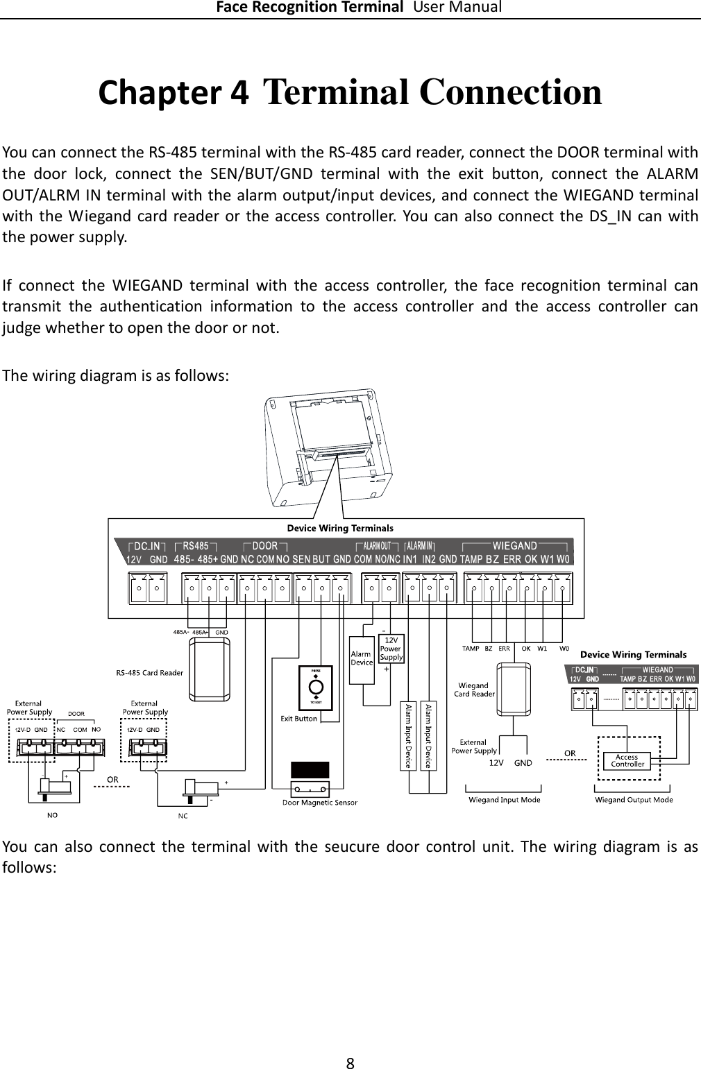
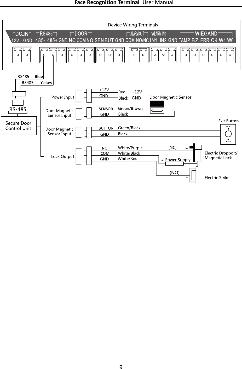
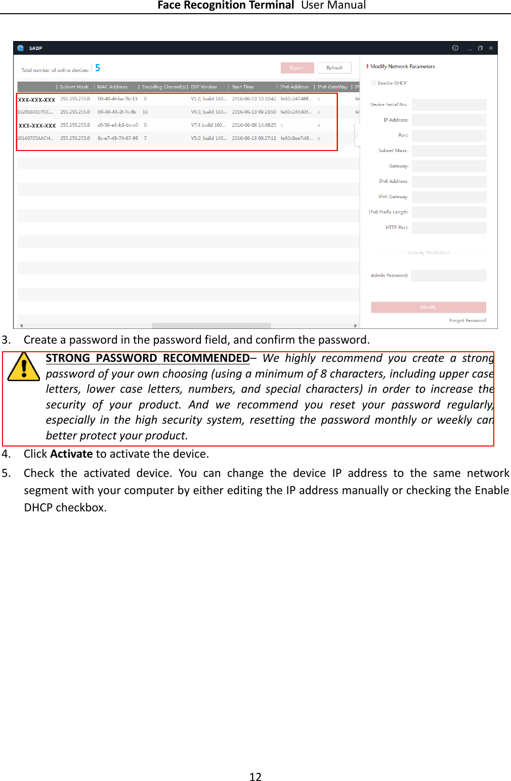
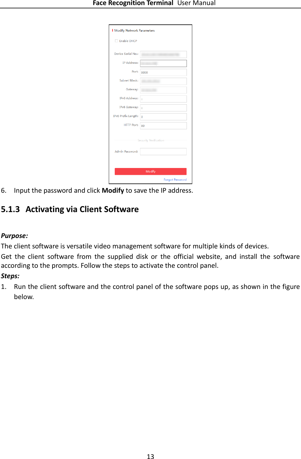
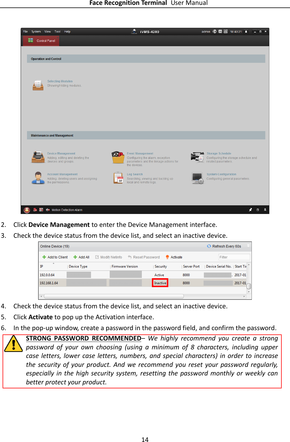
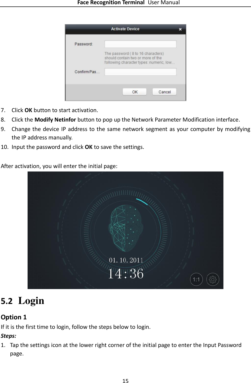
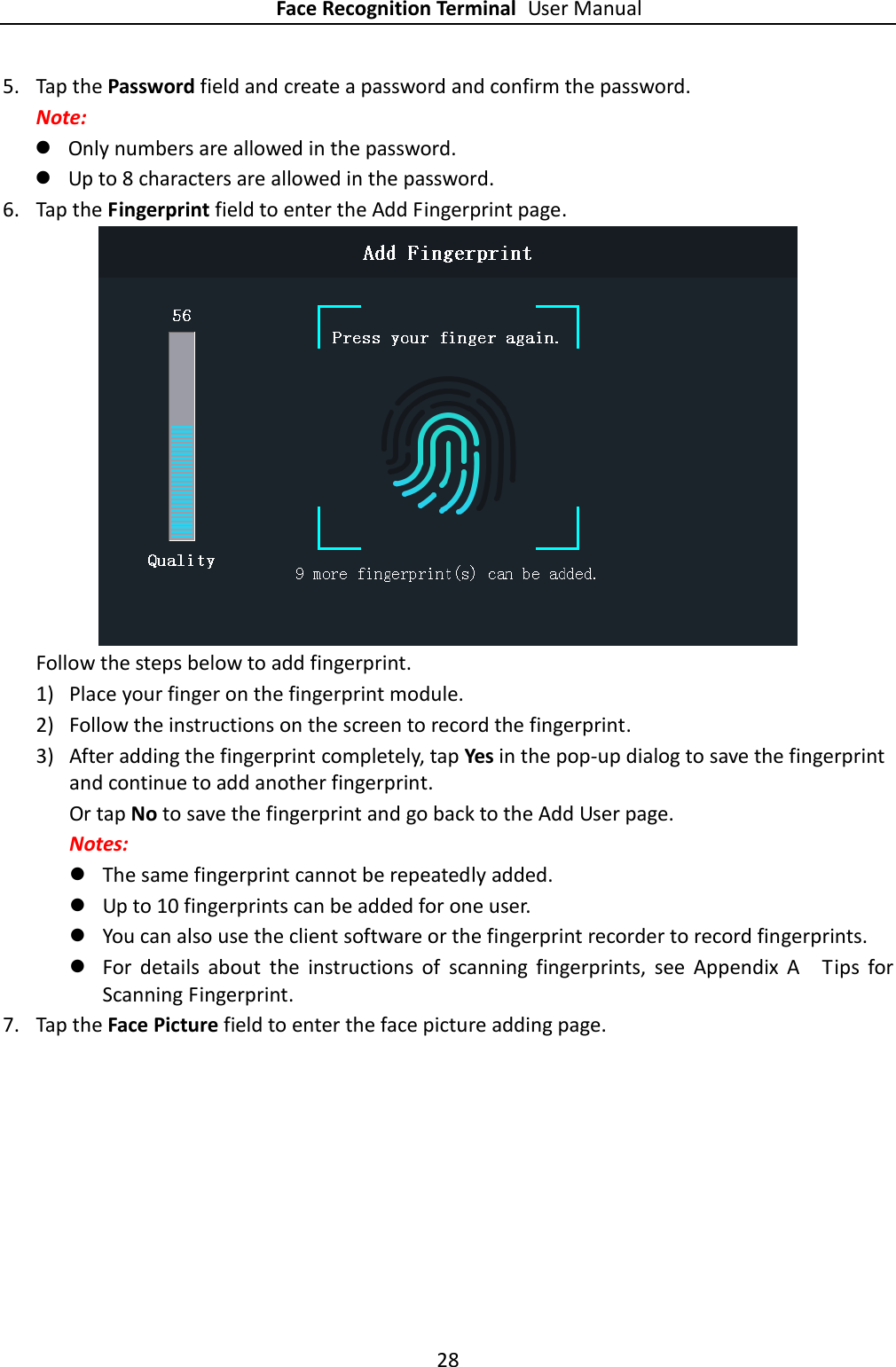
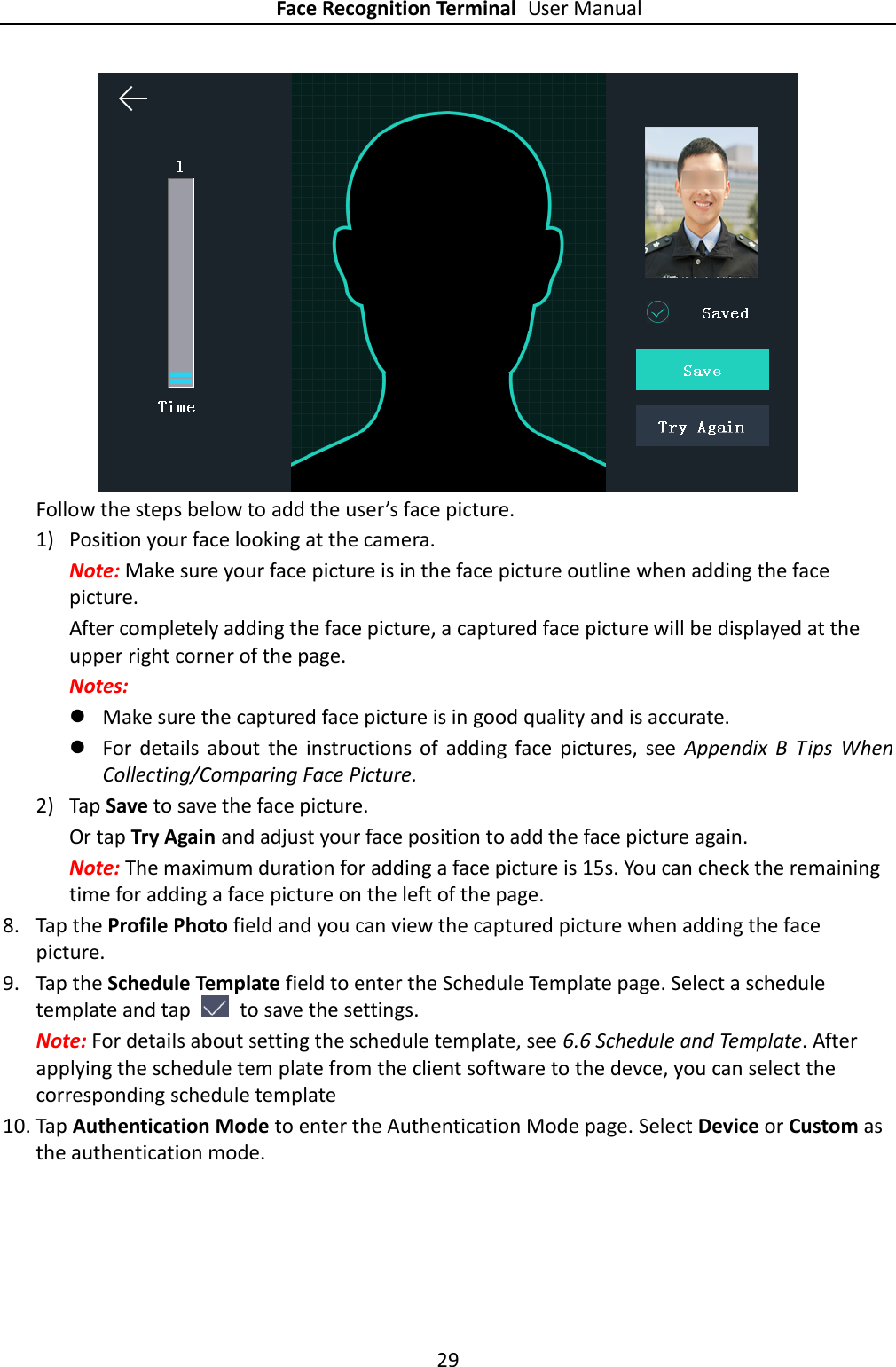
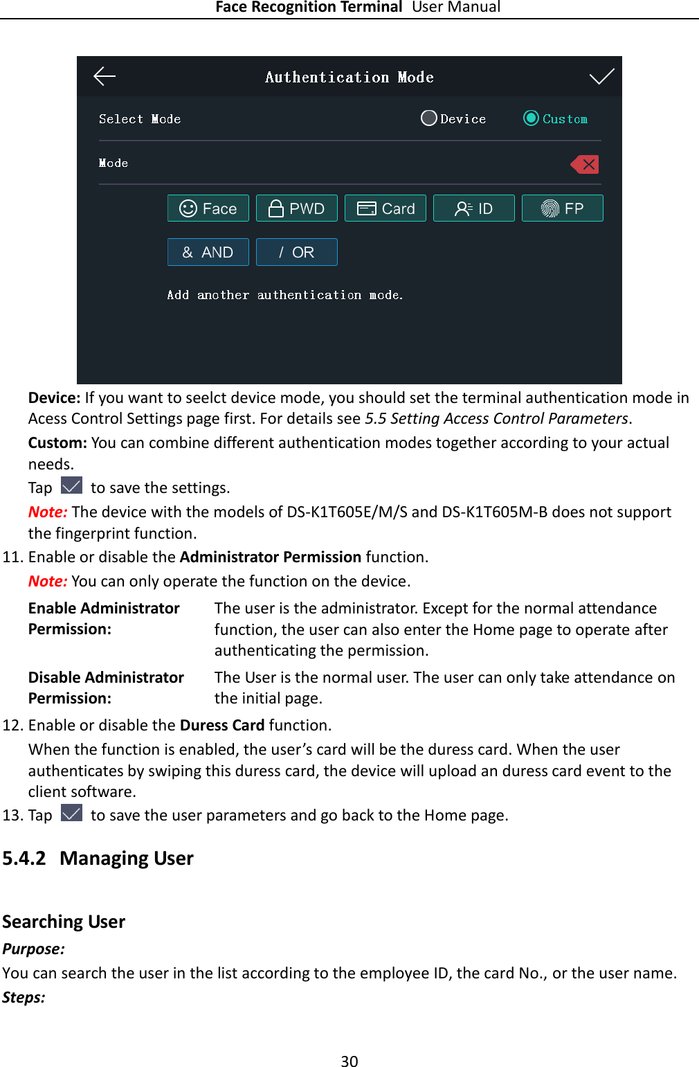
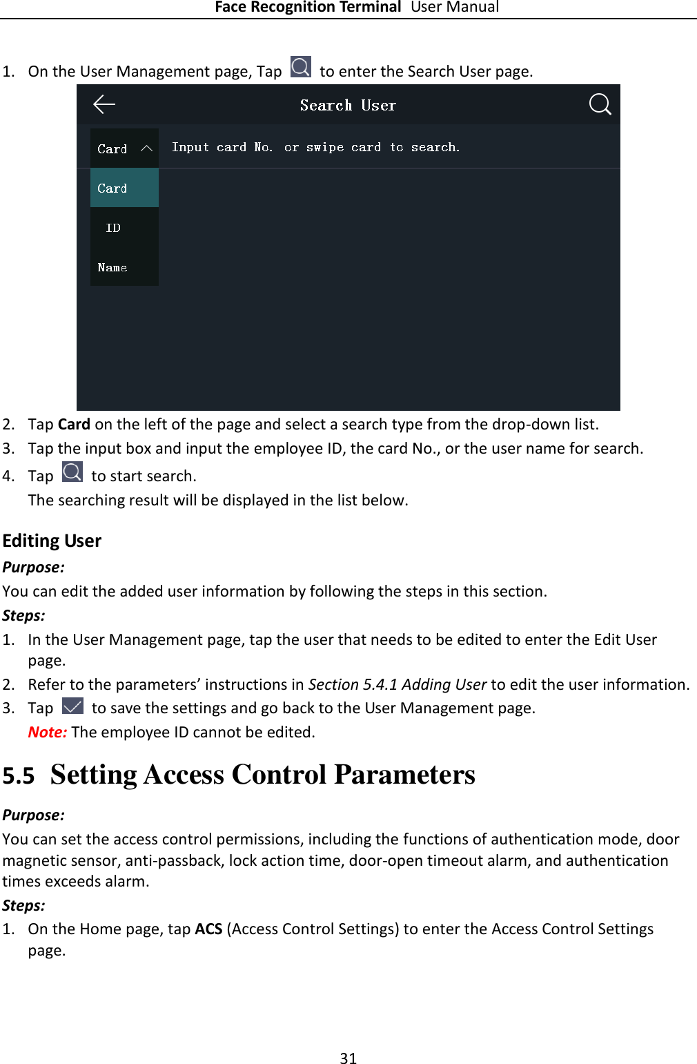
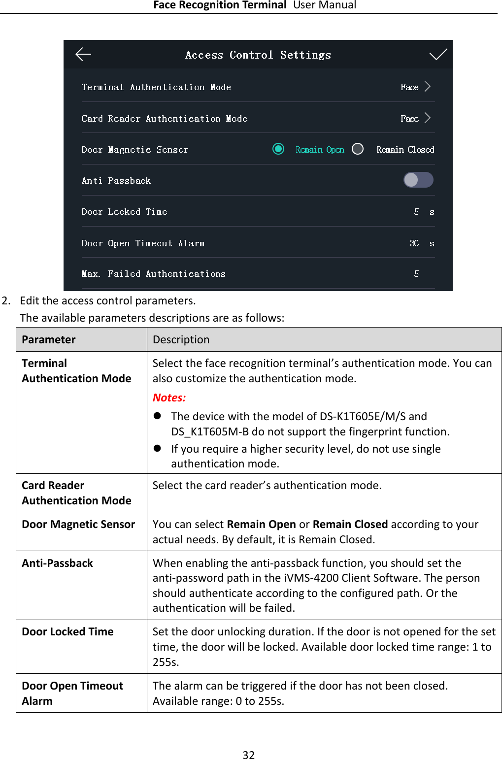
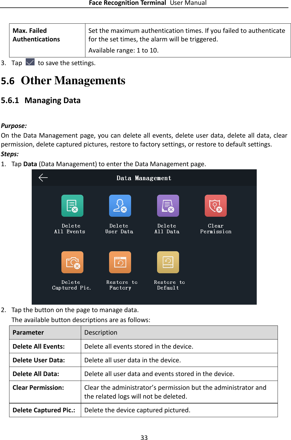
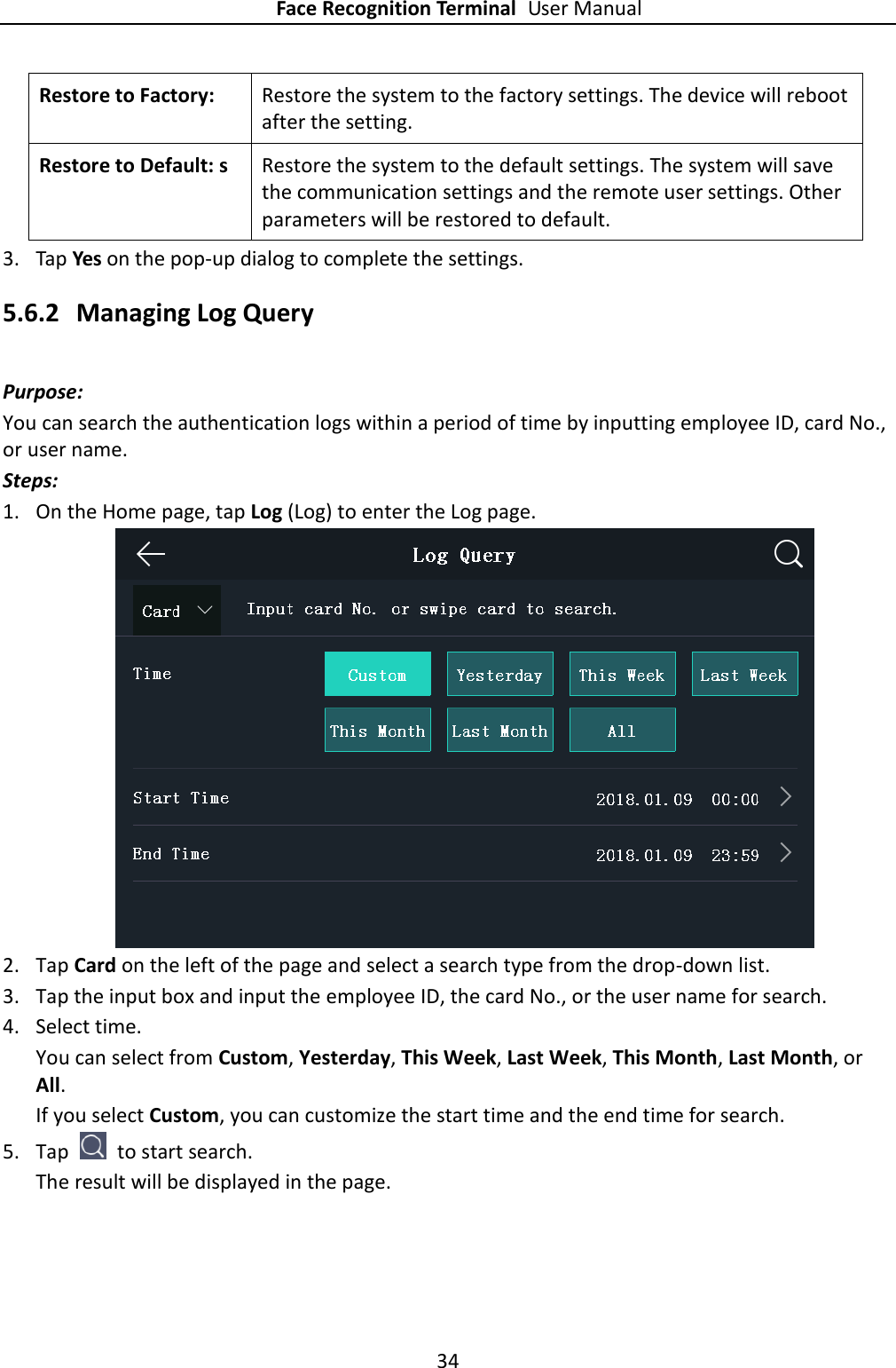
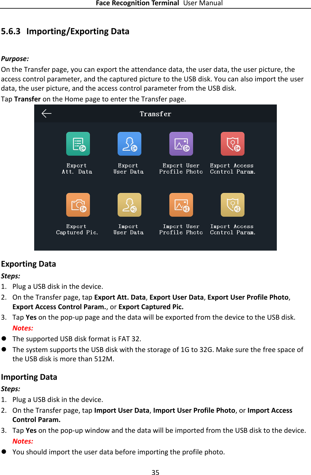
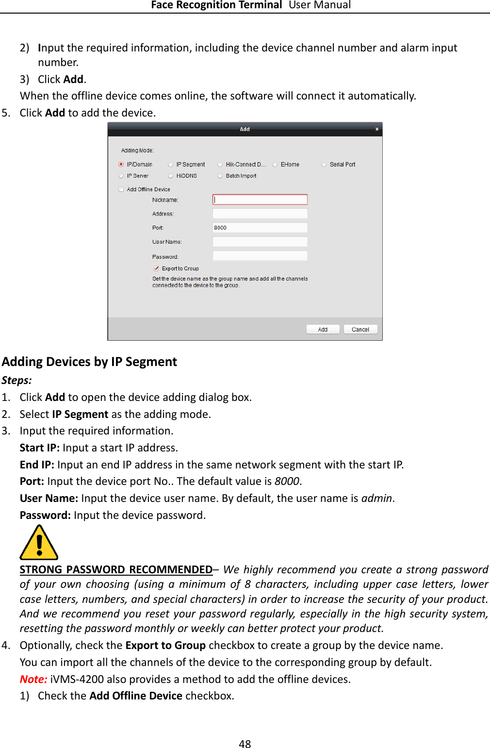
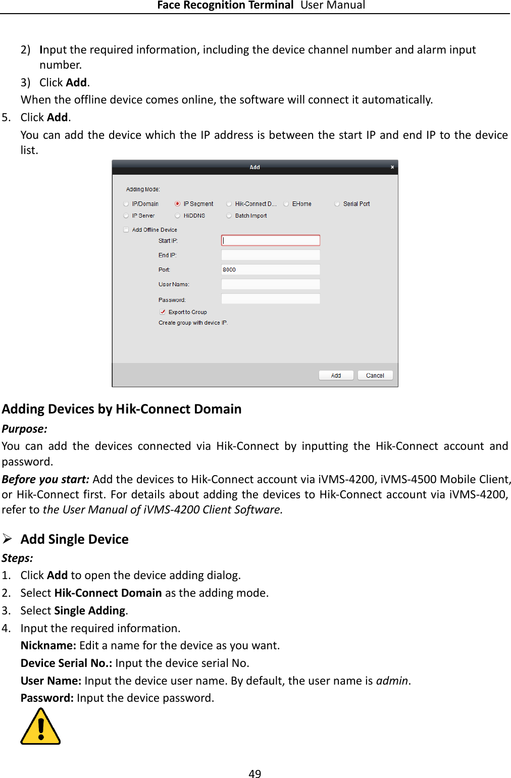
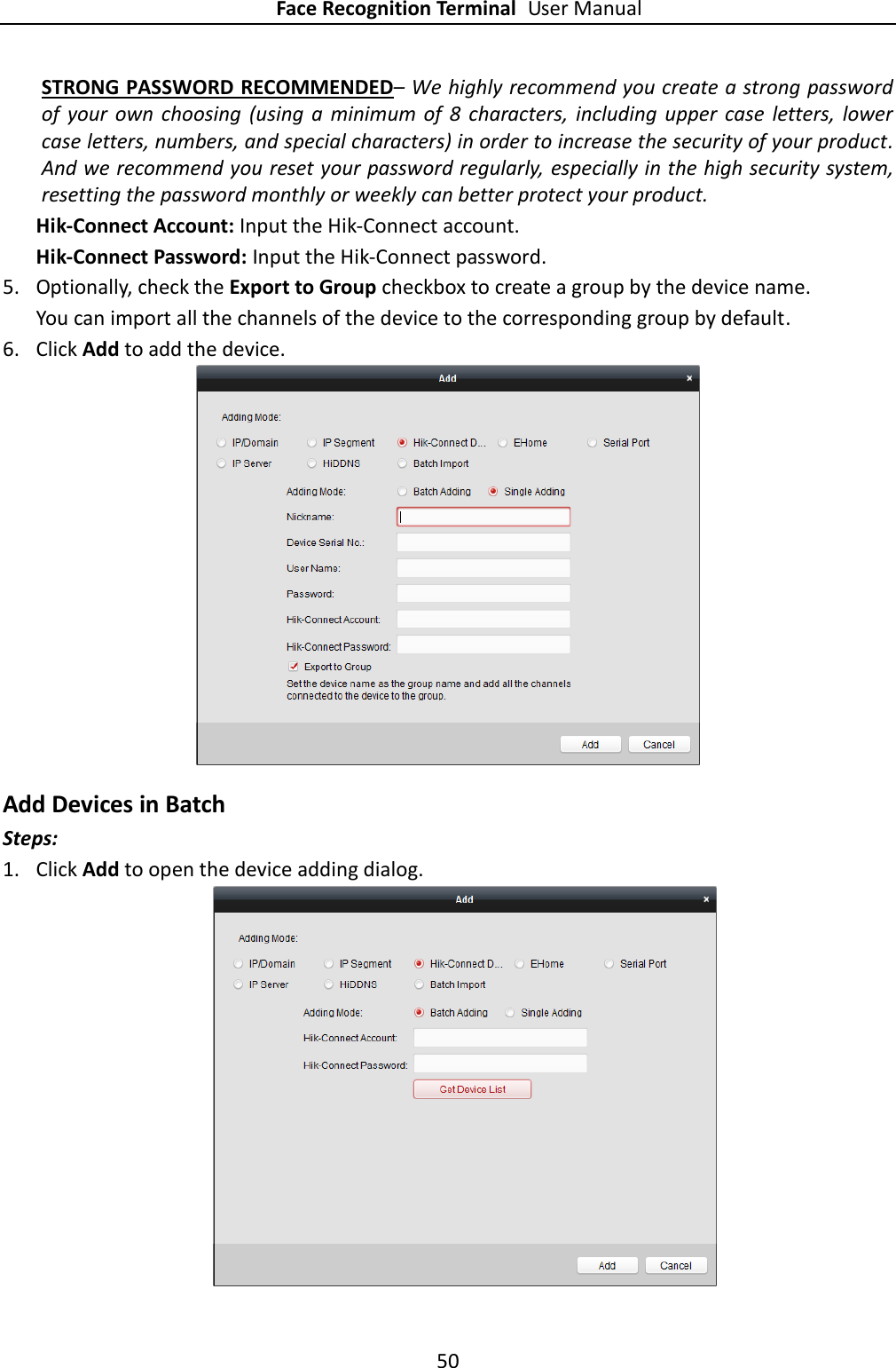
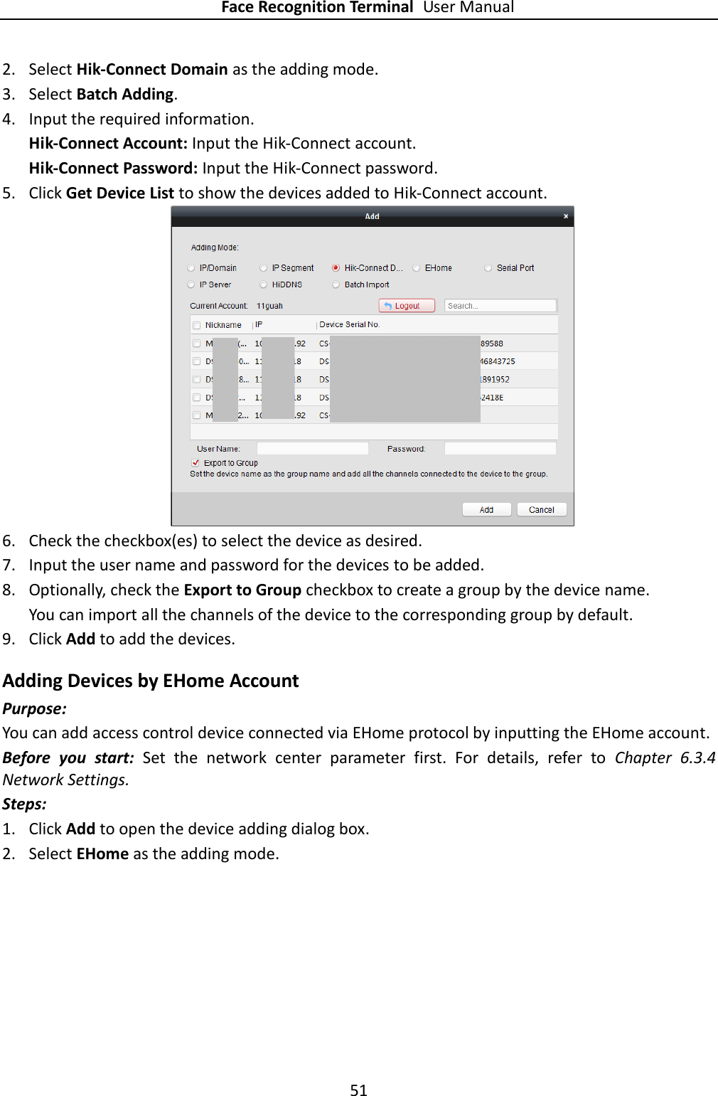
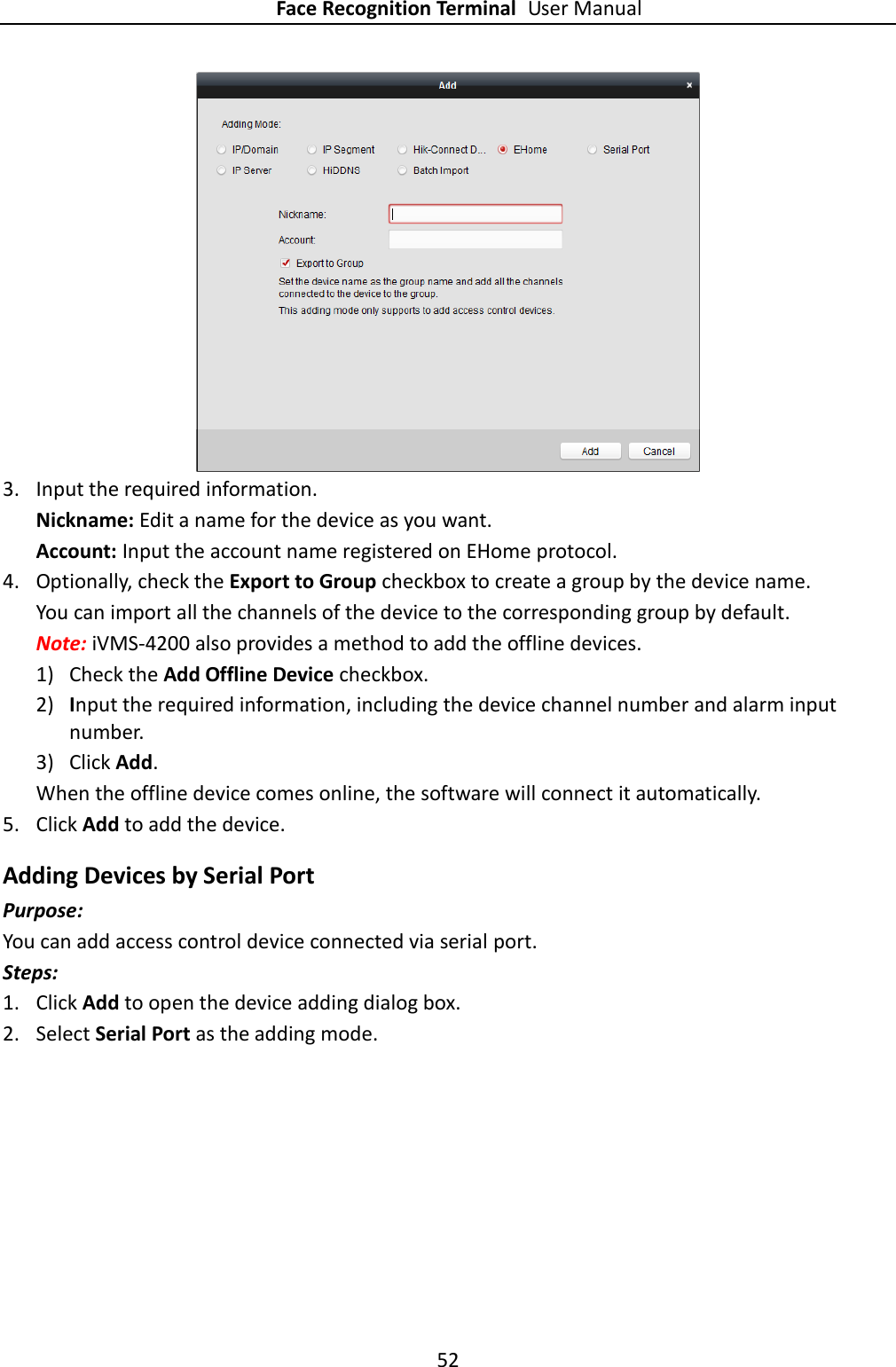
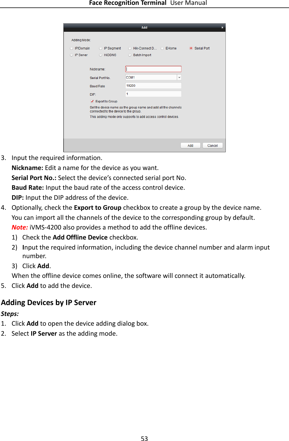
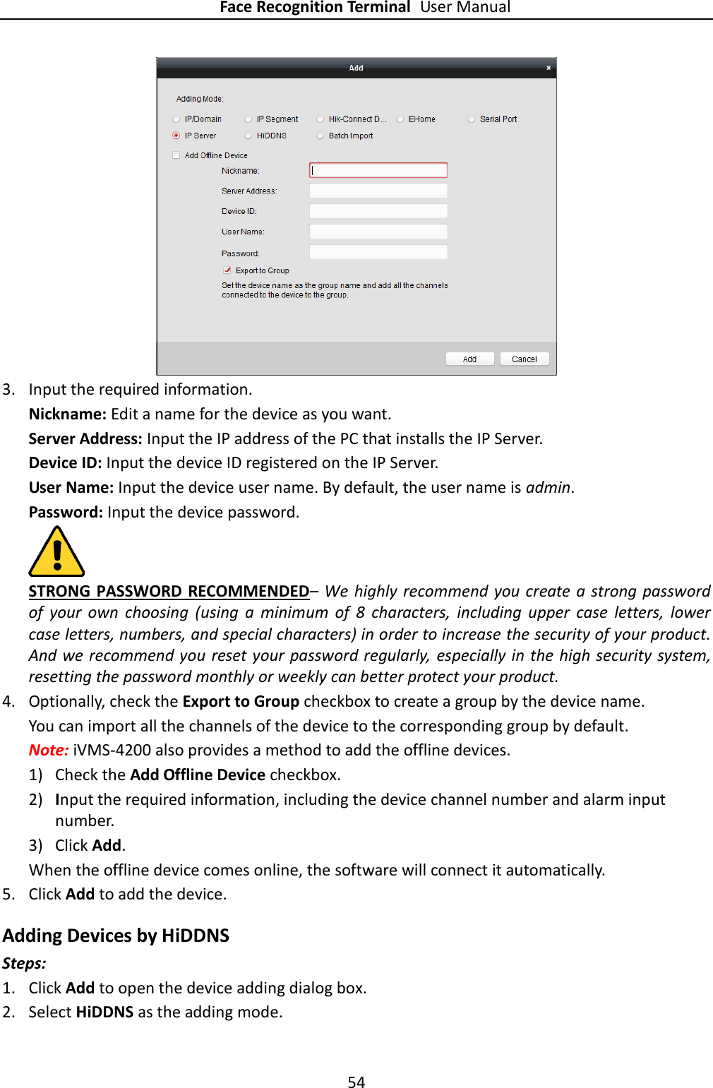
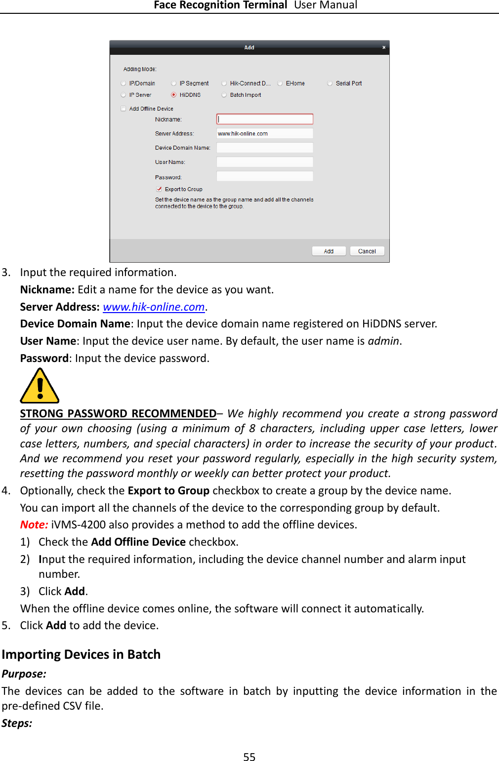
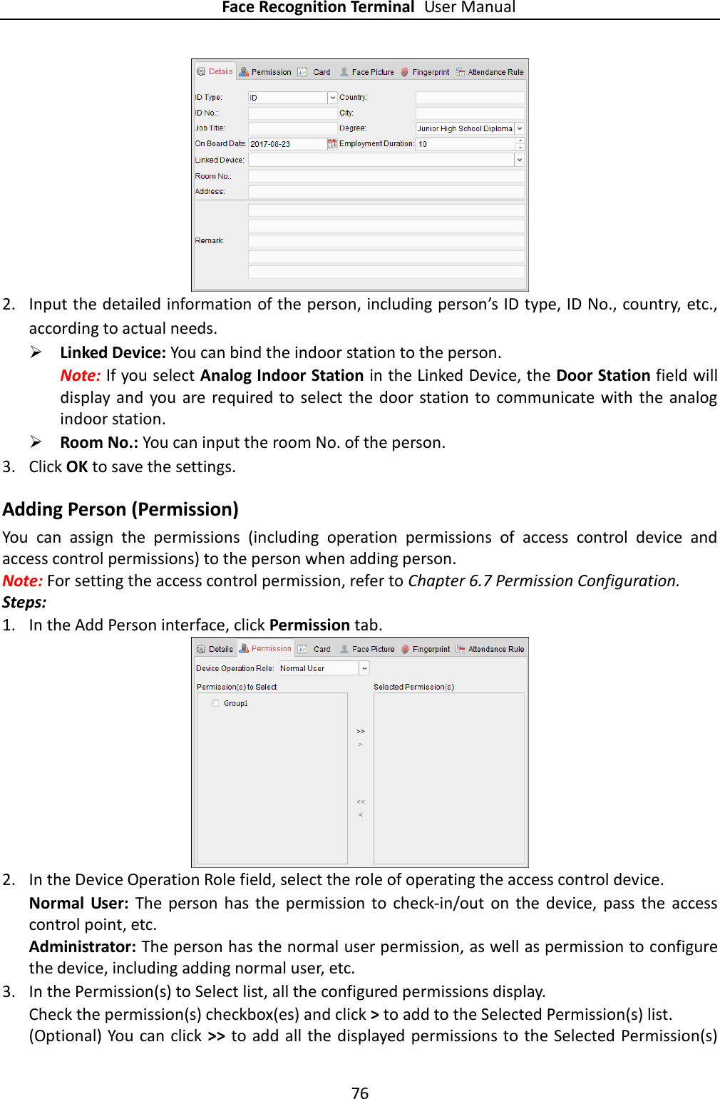
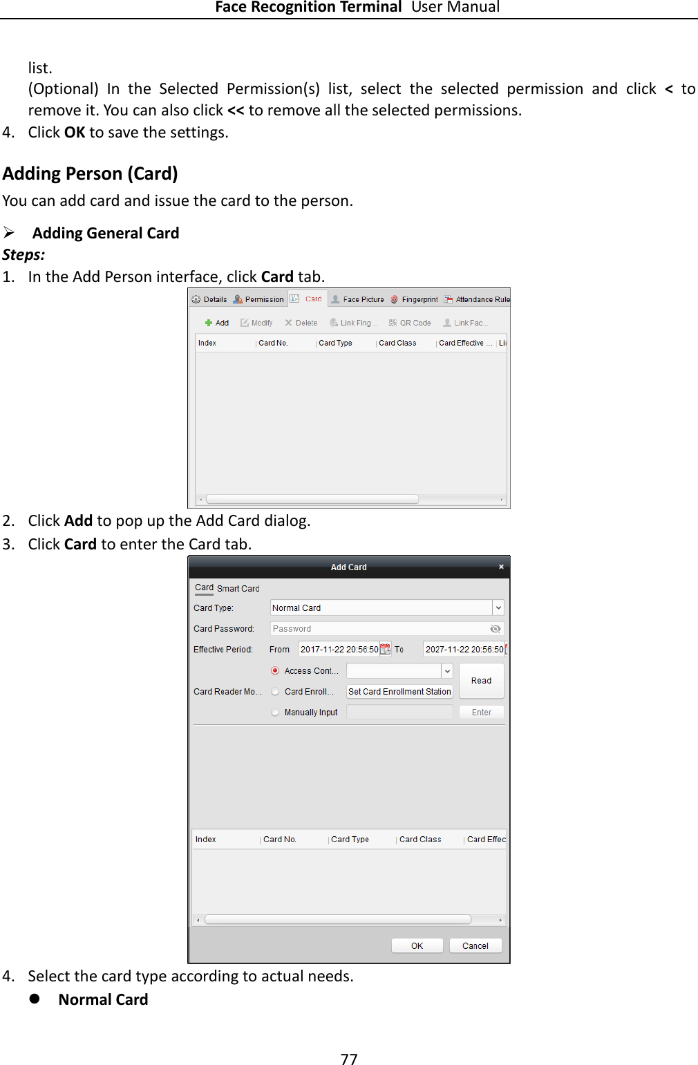
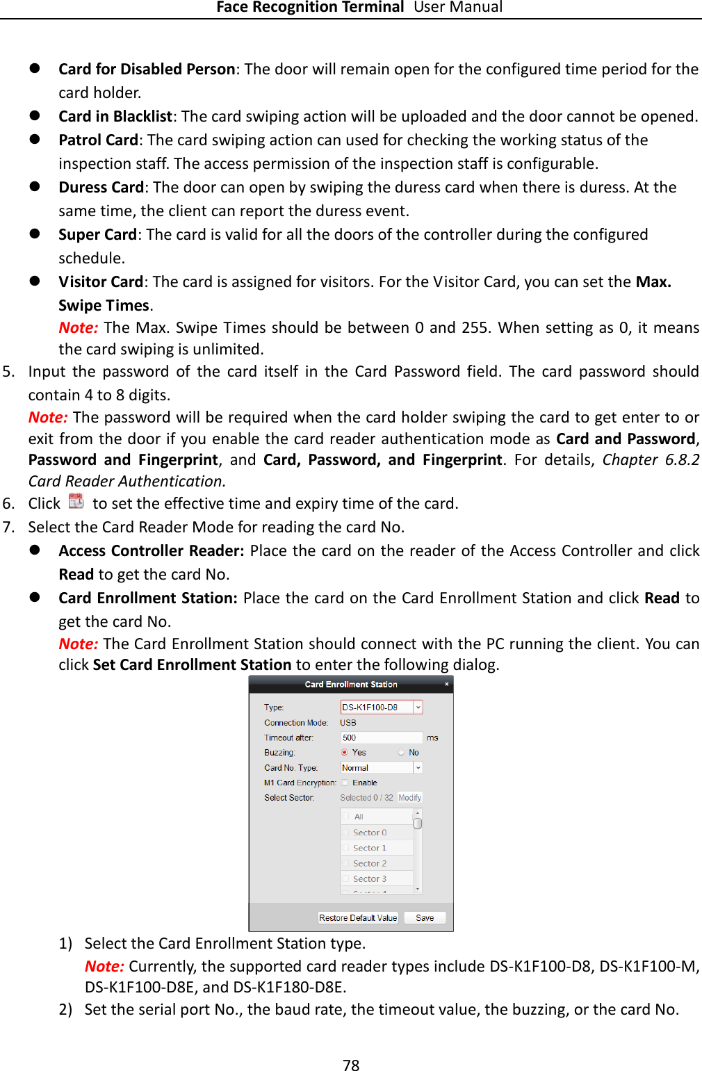
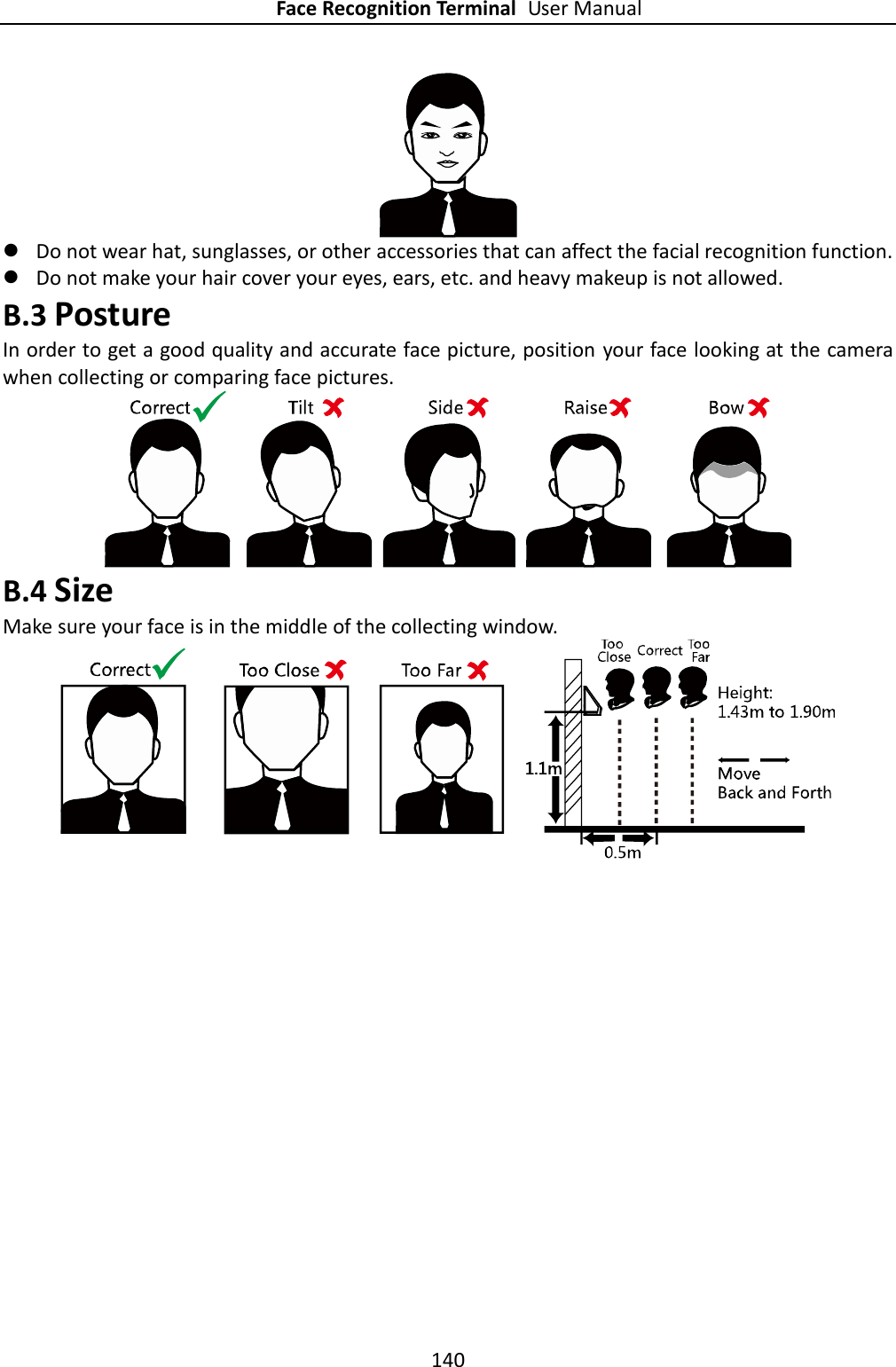
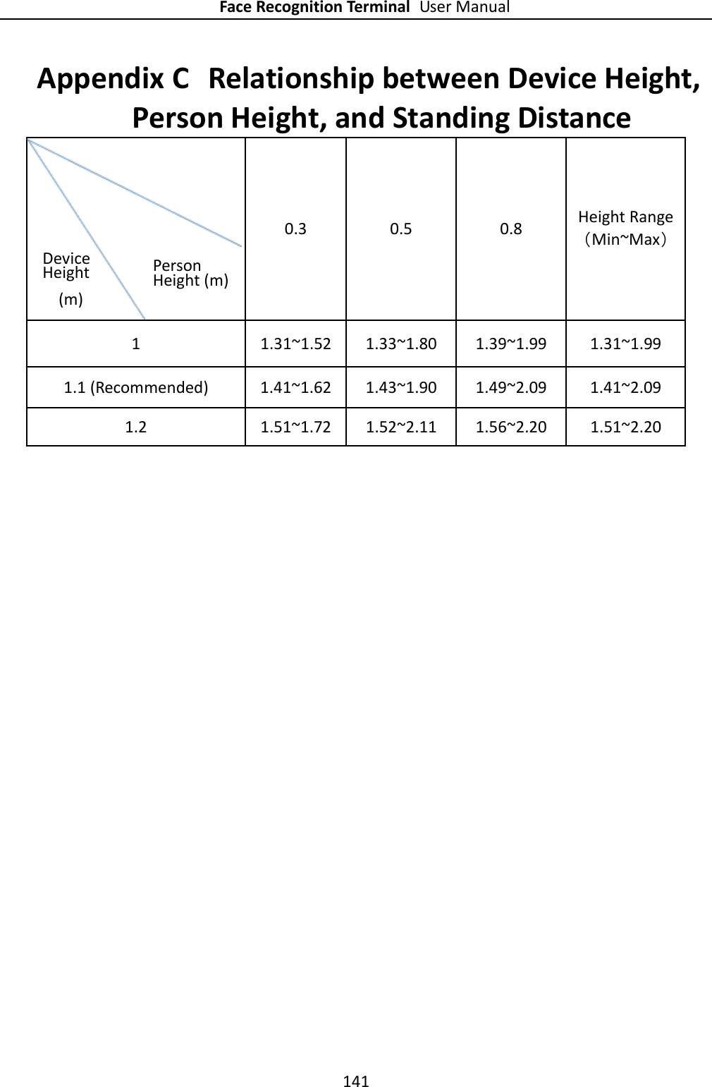
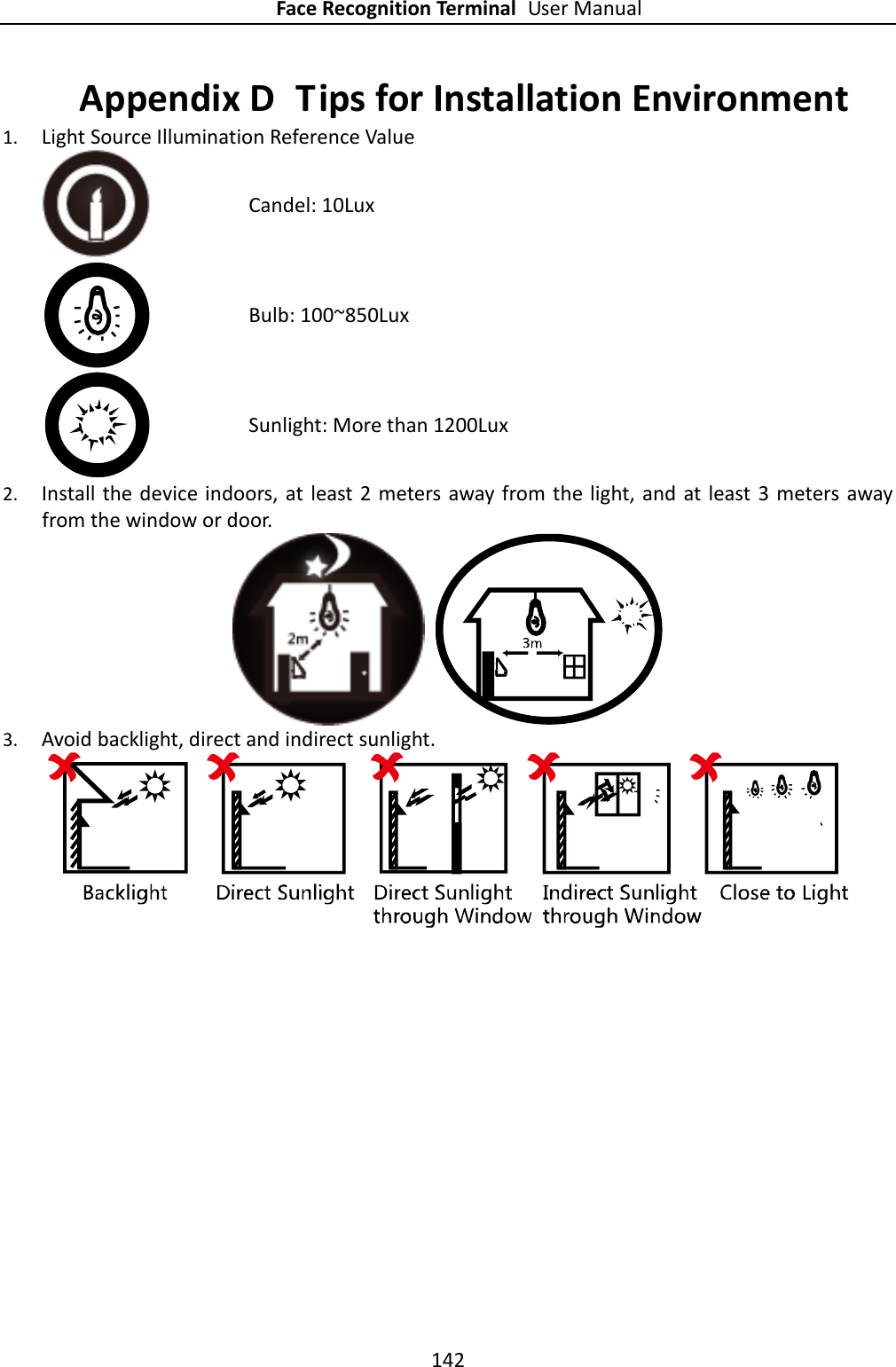
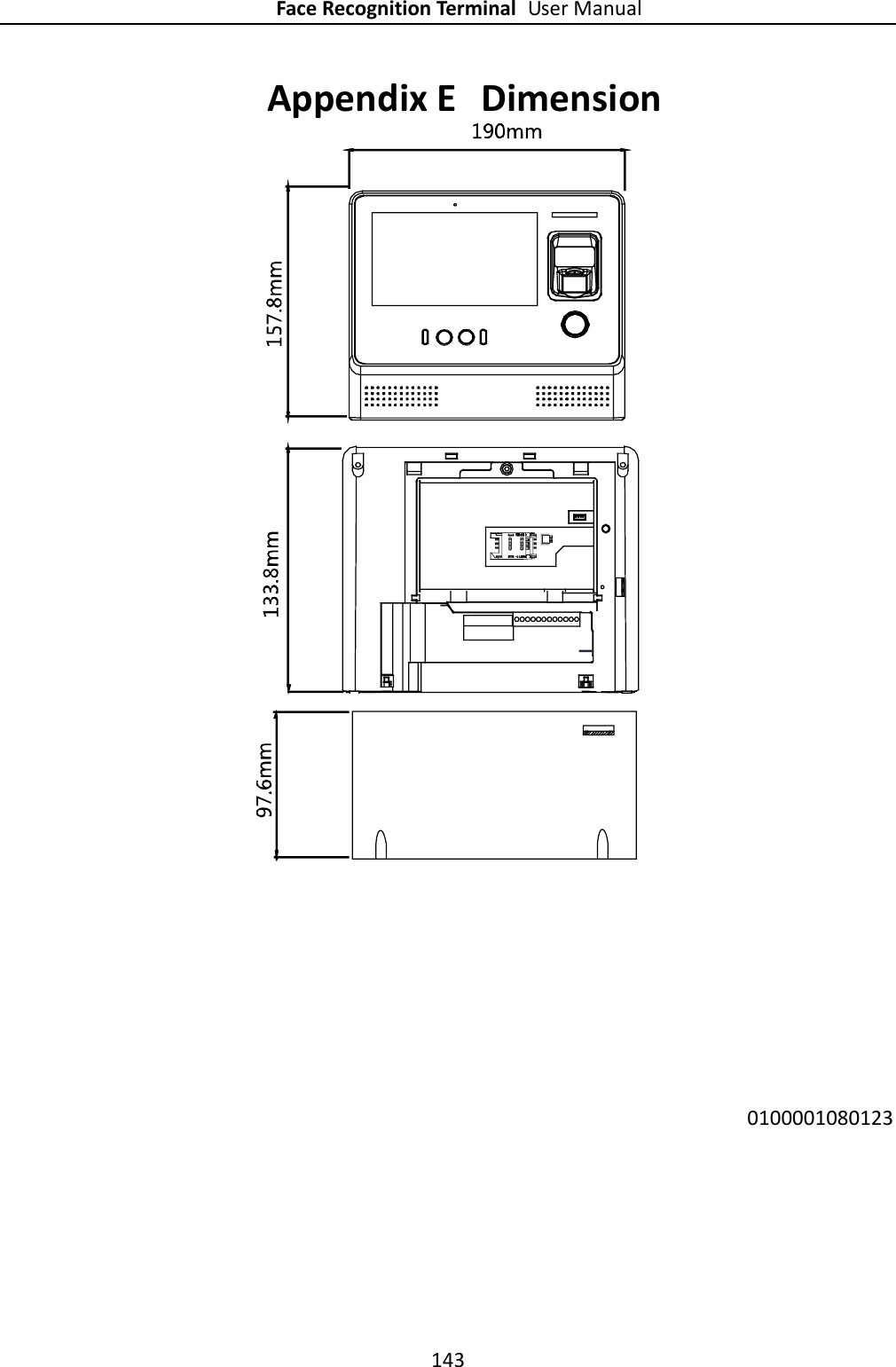
User Manual
Contents
1.
User Manual
2.
Users Manual
User Manual
Navigation menu
Upload a User Manual
Namespaces
Wiki Guide
HTML
PDF
Info
Views
User Manual
Discussion / Help
Navigation