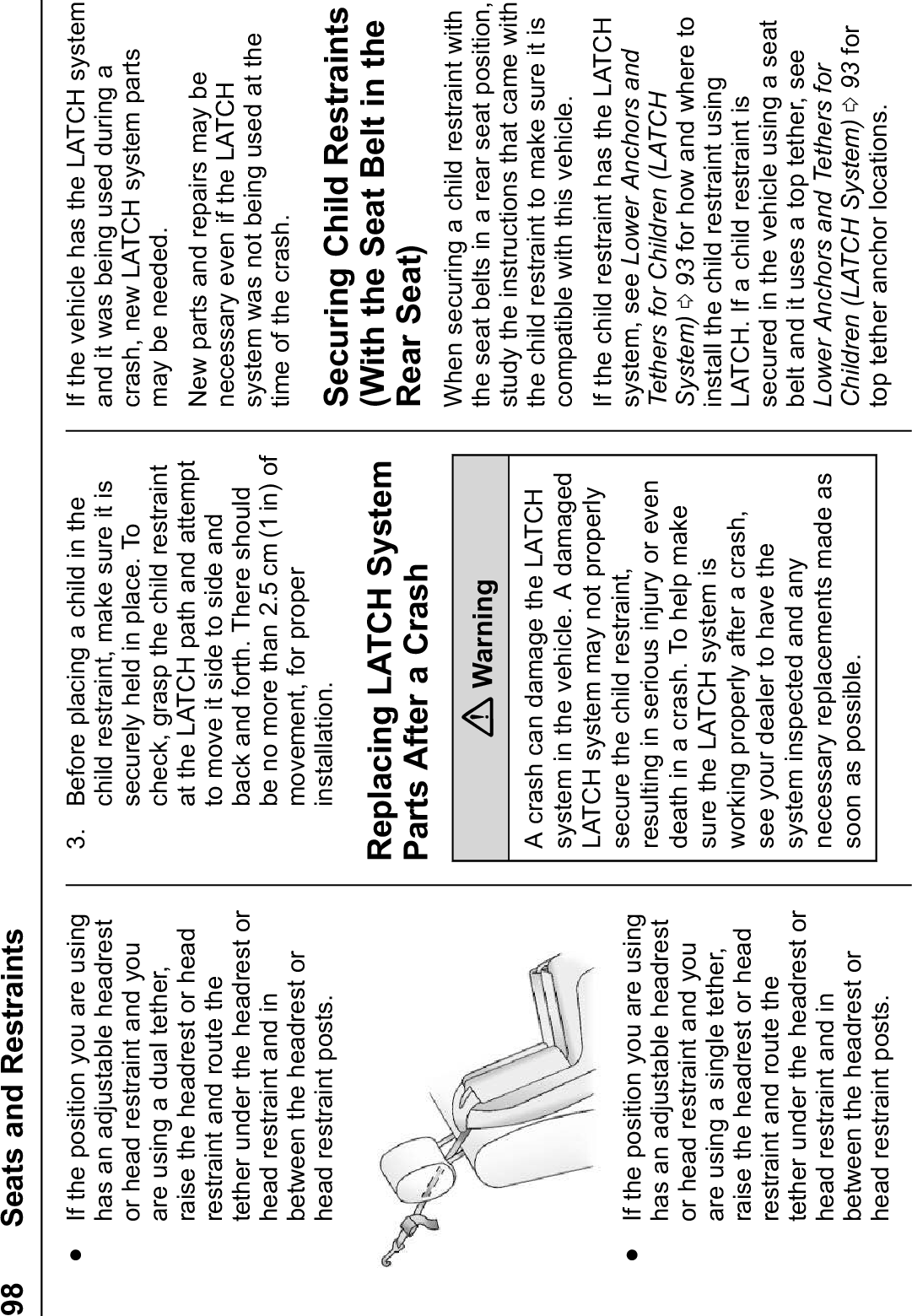
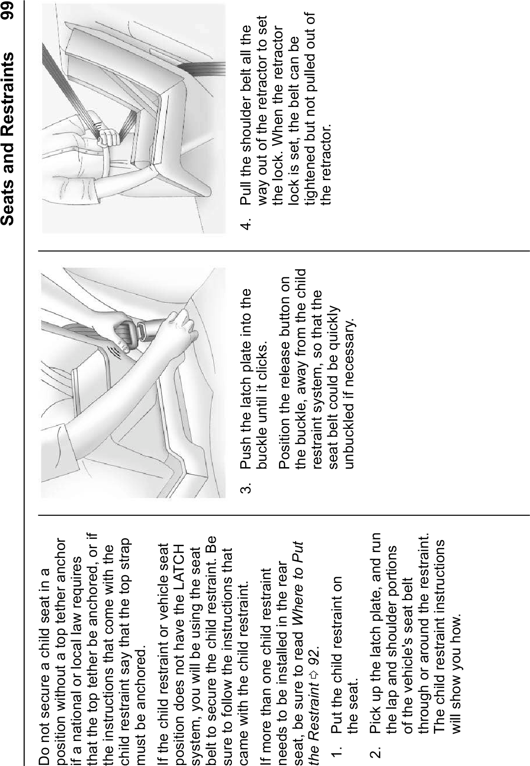
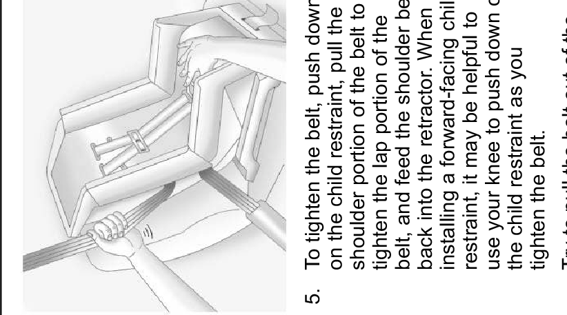
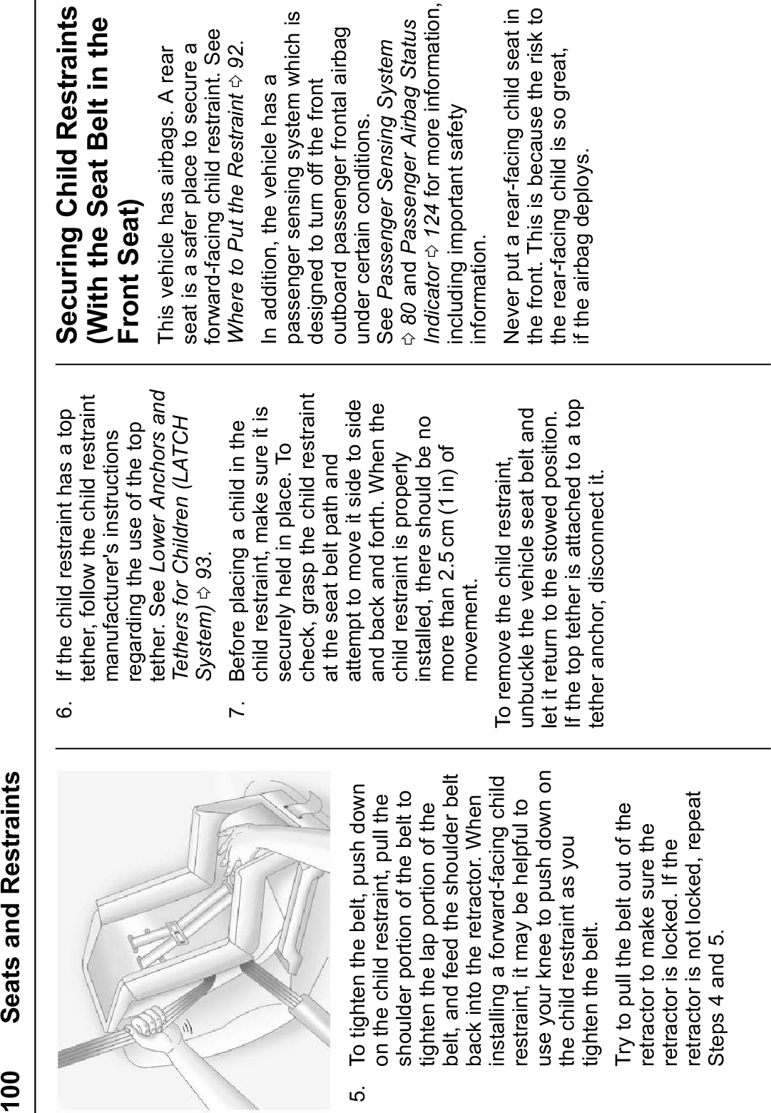
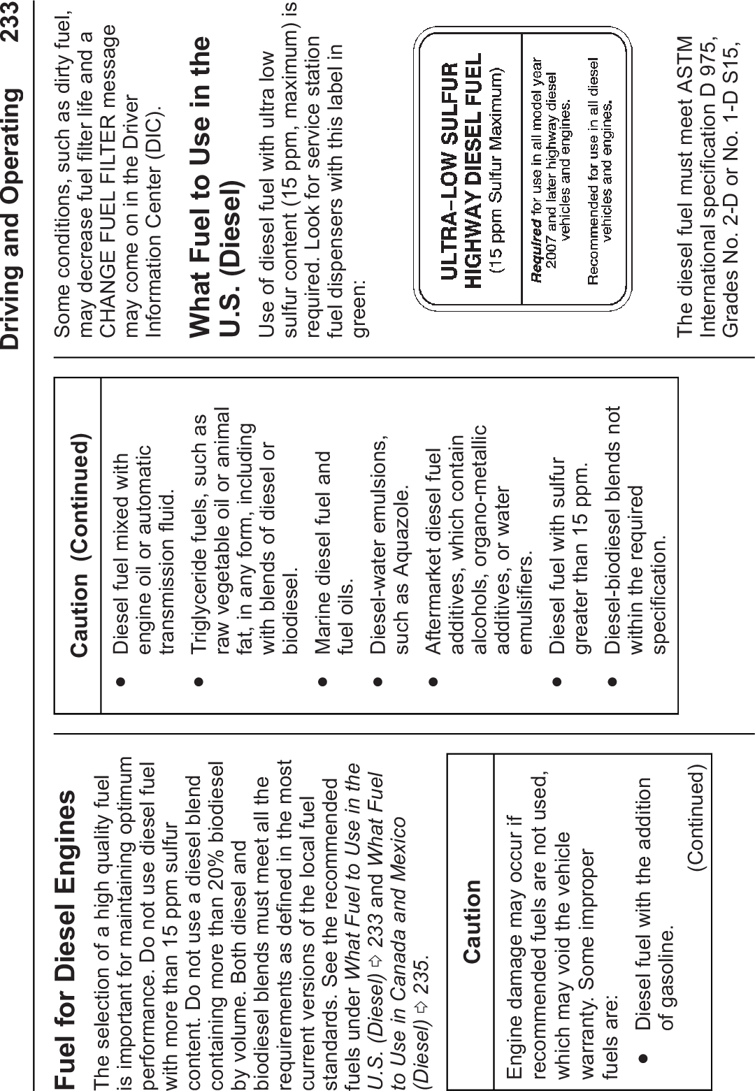
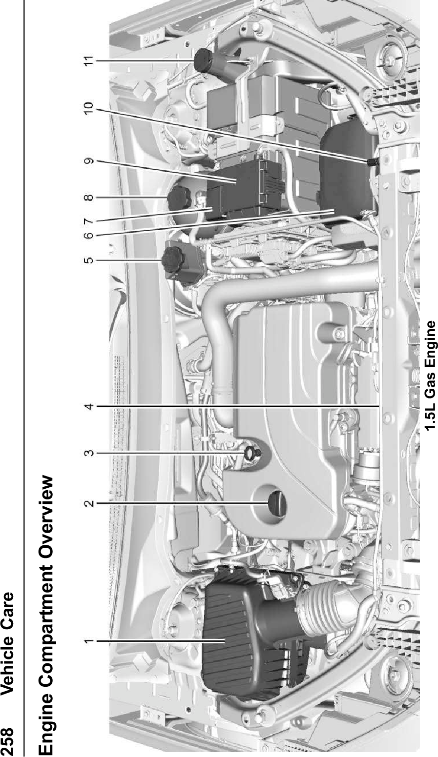
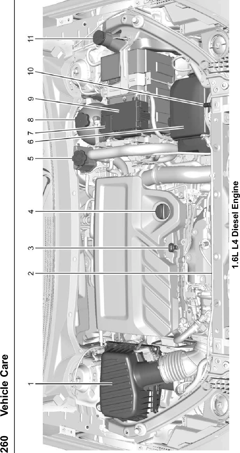
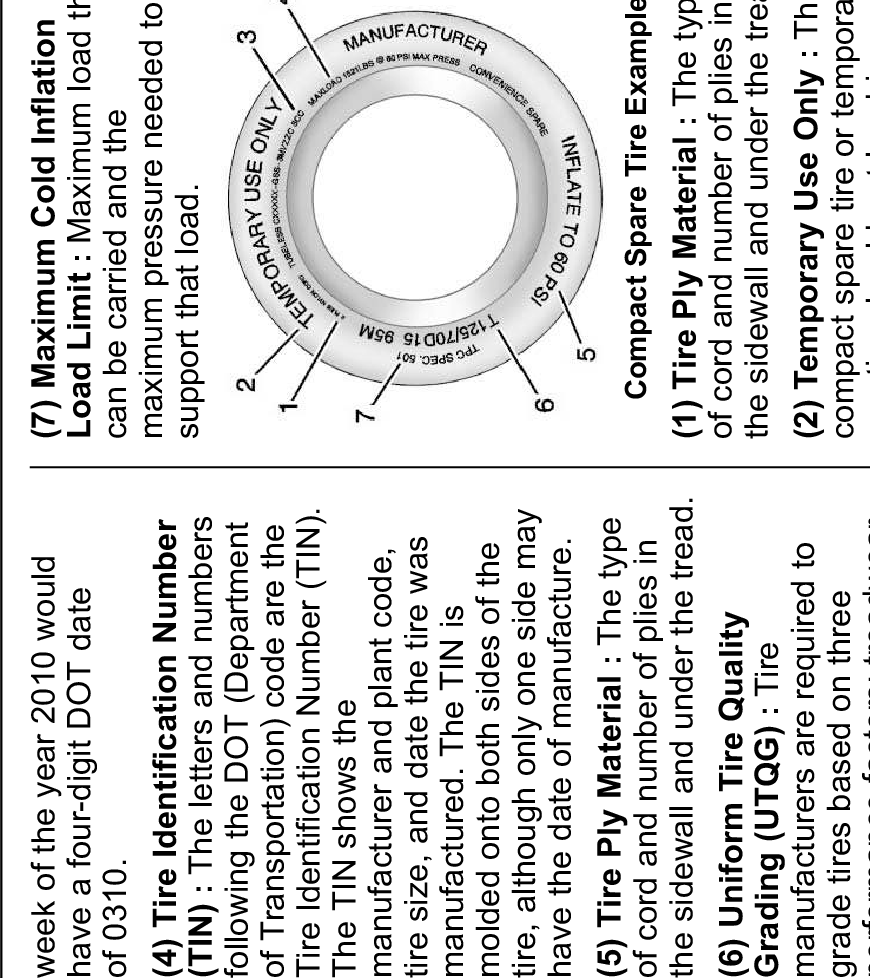
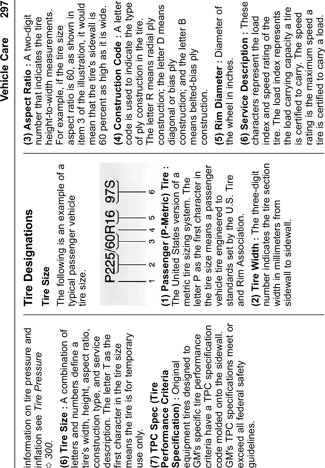
Harman BE2828 Automotive Infotainment Unit with Bluetooth/WLAN User Manual
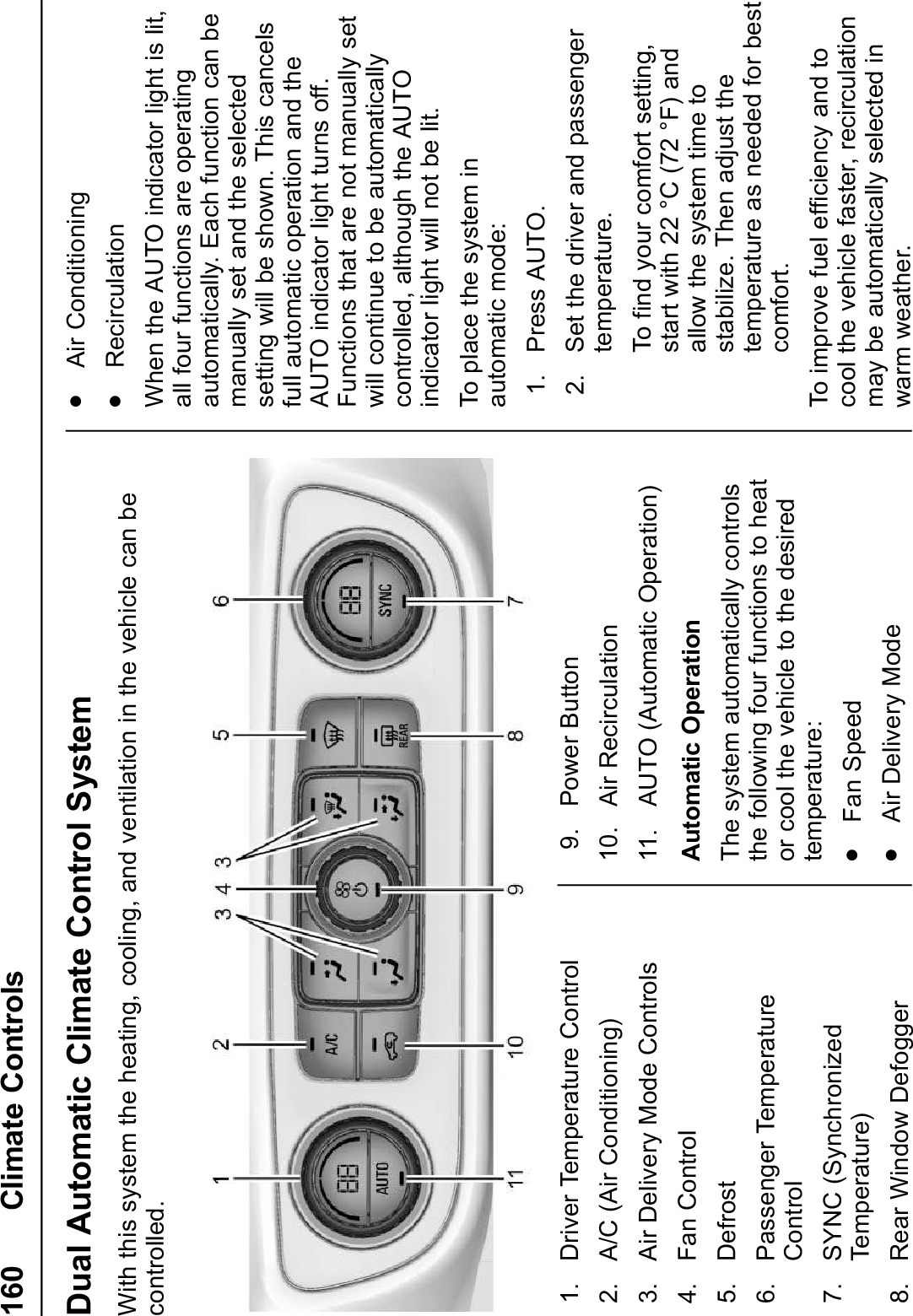
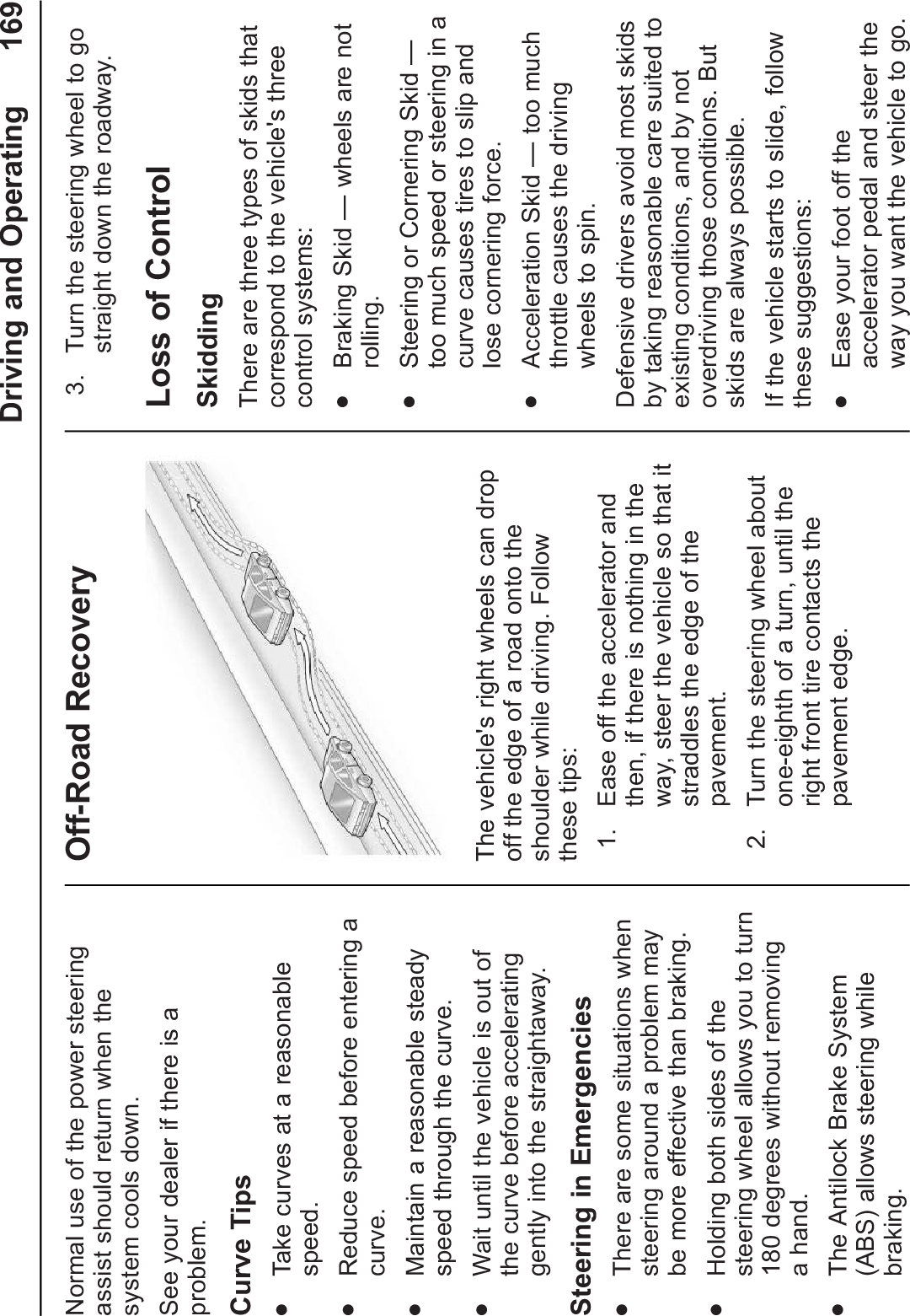
Harman International Industries, Inc. Automotive Infotainment Unit with Bluetooth/WLAN Users Manual
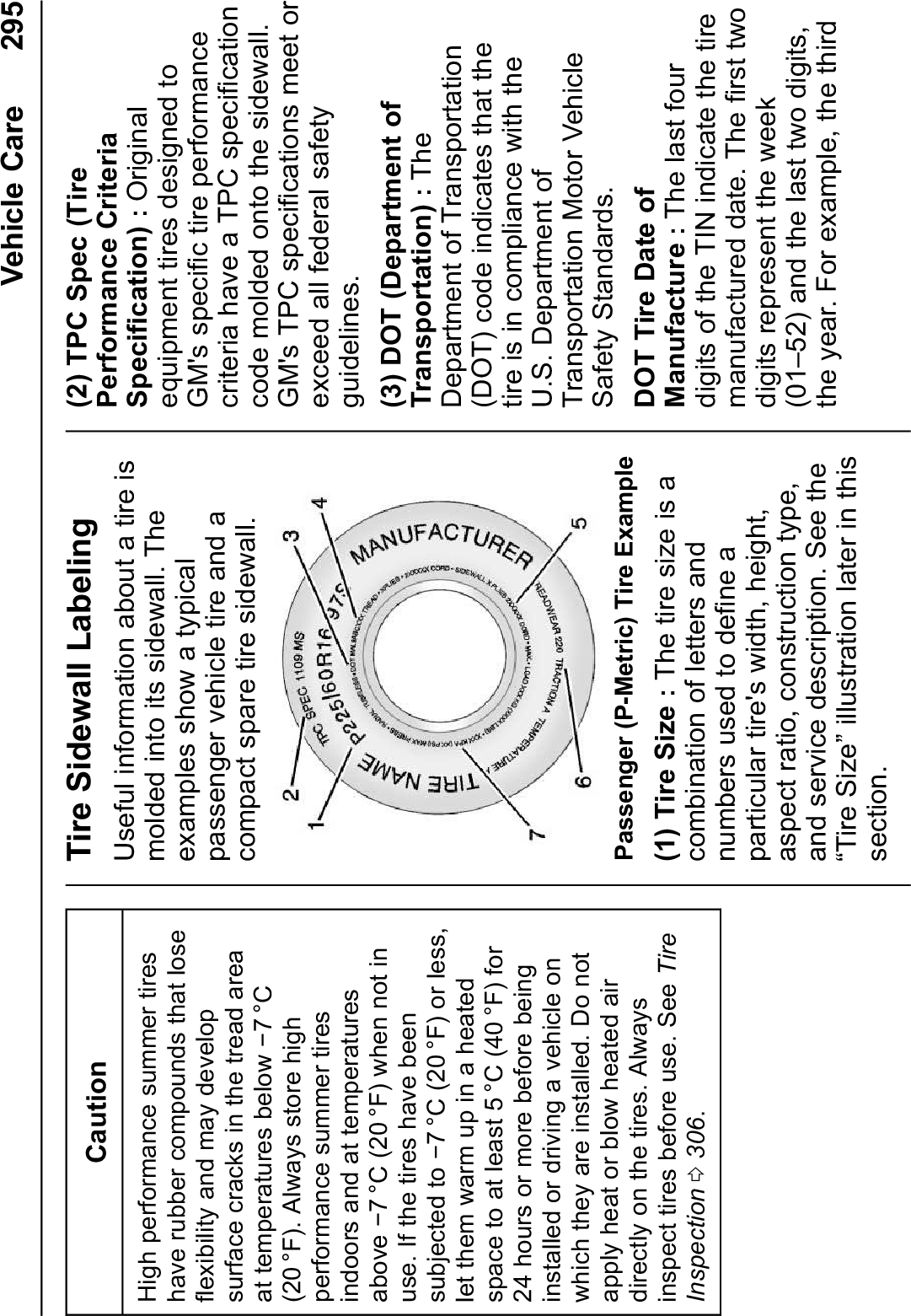
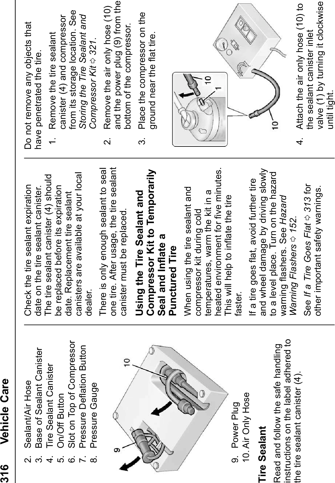
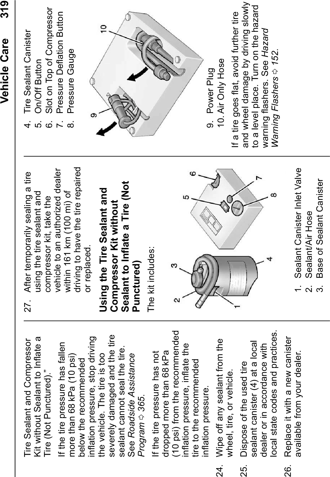
UserManual.wiki
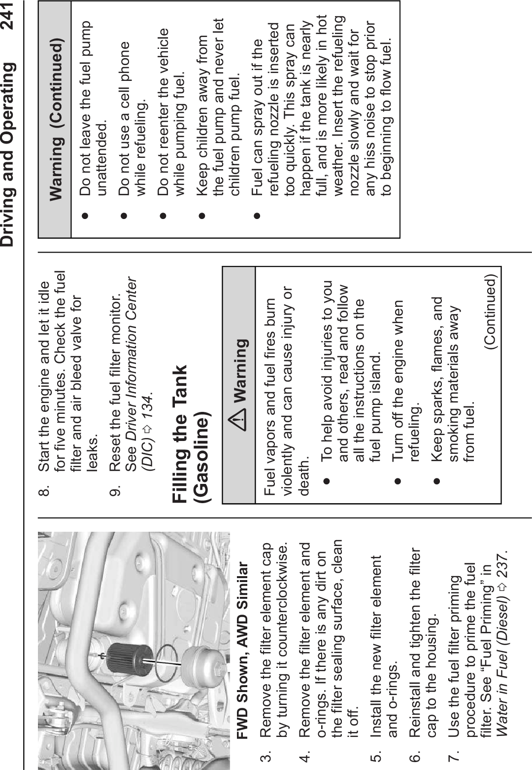
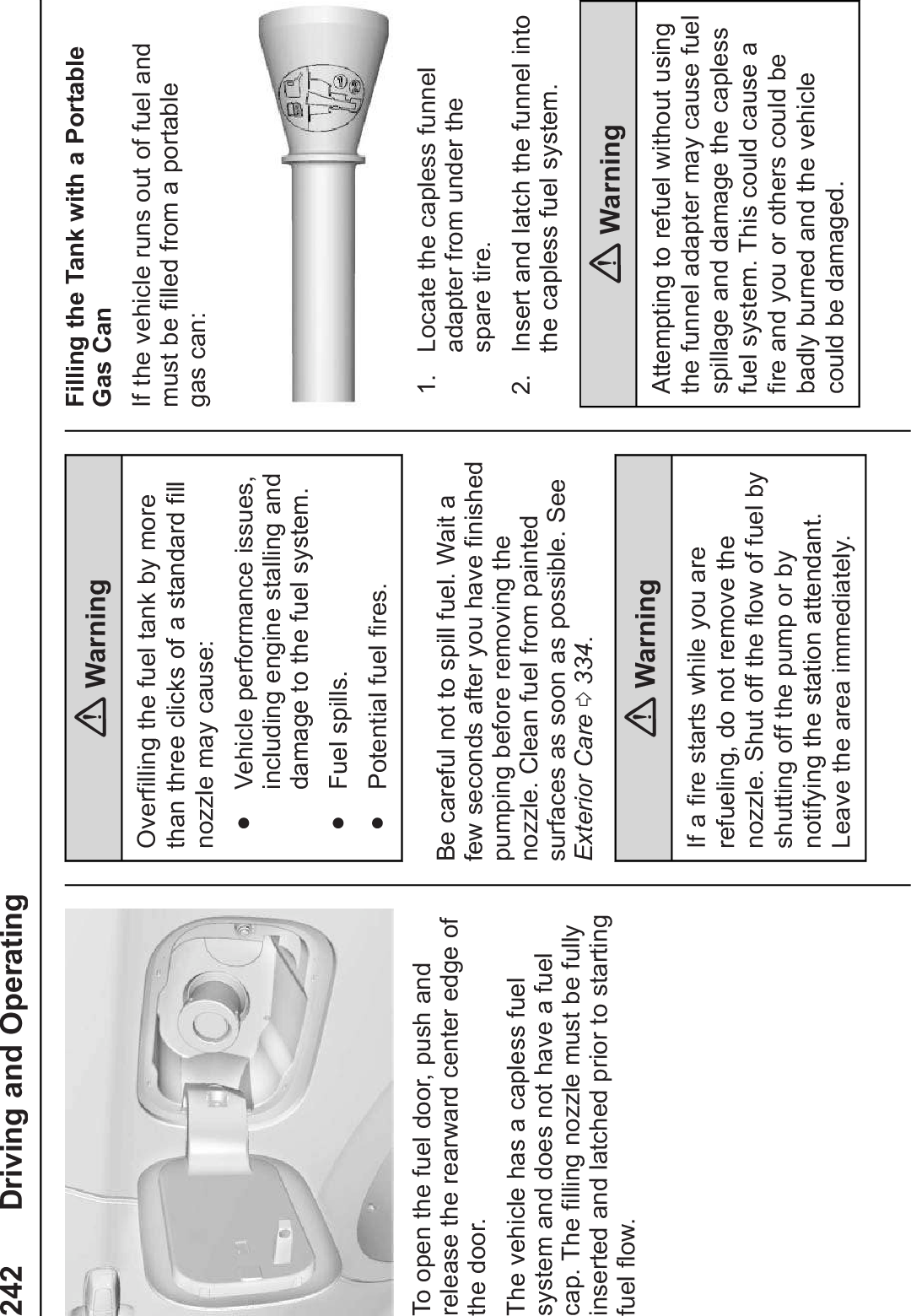
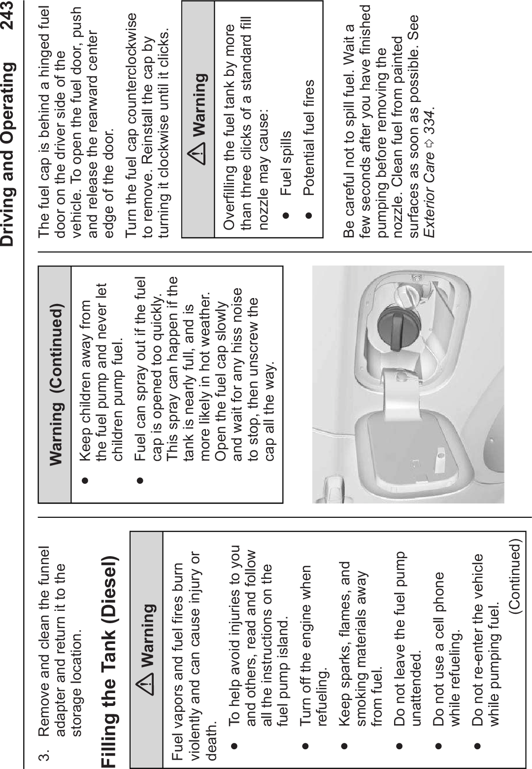
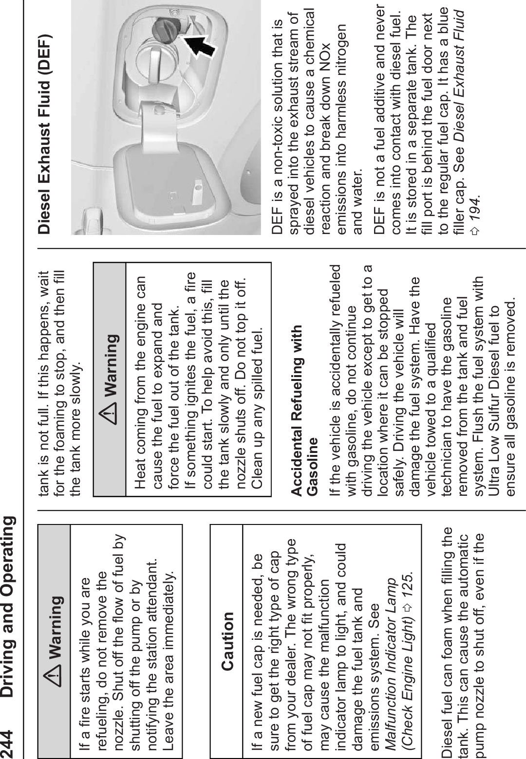
>
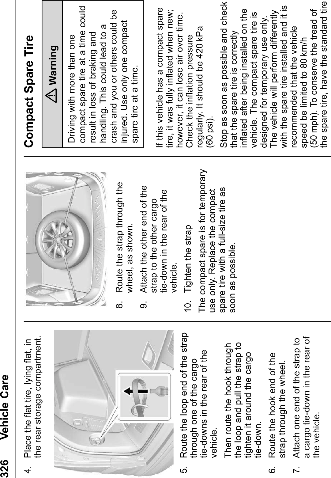
Harman
>
BE2828 User Manual
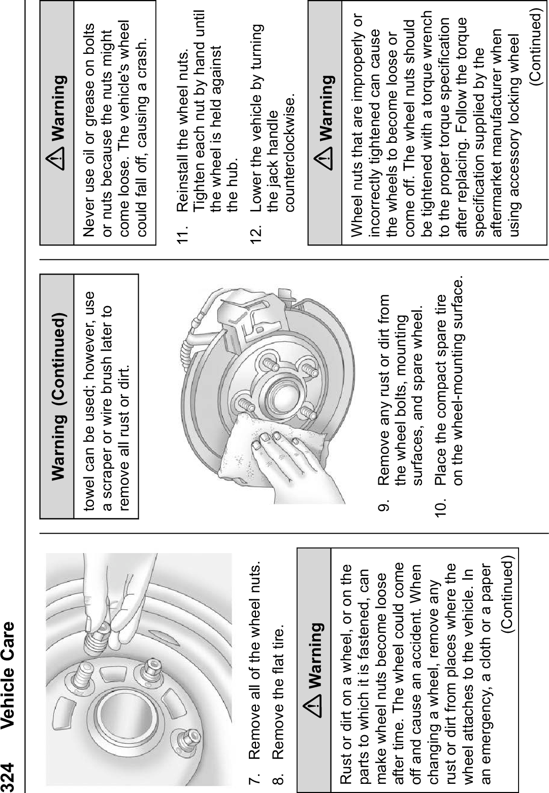
Users Manual
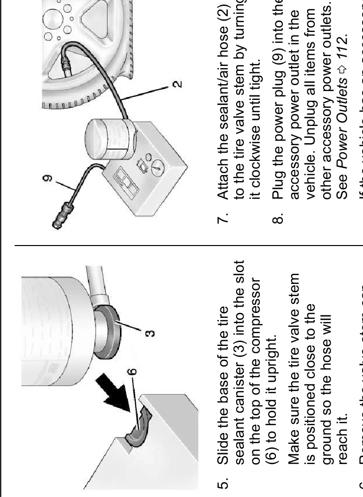
Navigation menu
Upload a User Manual
Namespaces
Wiki Guide
HTML
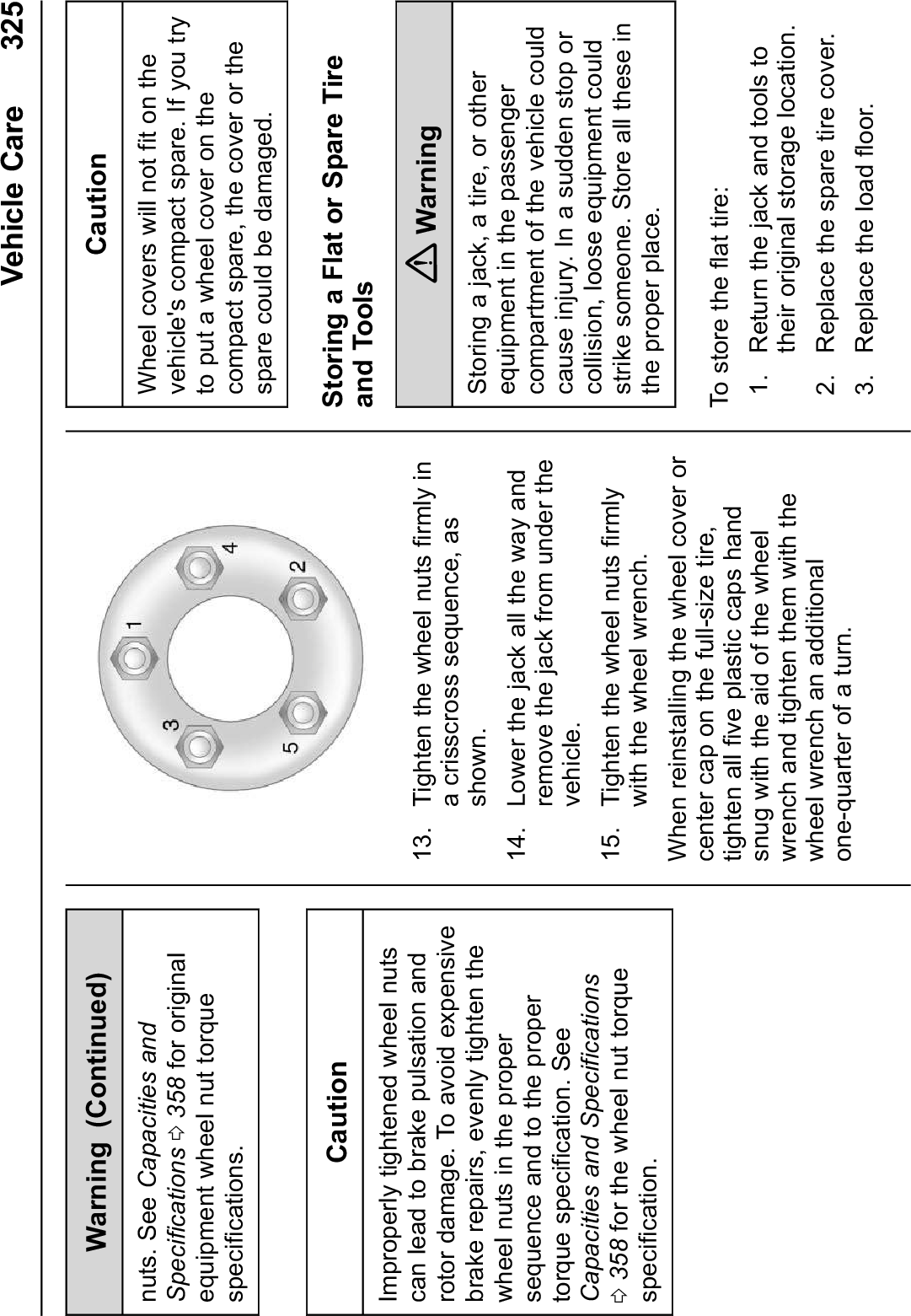
PDF
Info
Views
User Manual
Discussion / Help
Navigation