Lavi 95QT QTRAC REMOTE User Manual 1 of 2
Lavi Industries QTRAC REMOTE 1 of 2
UserManual.wiki
>
Lavi
>
95QT User Manual
>
User manual 1 of 2
Contents
1.
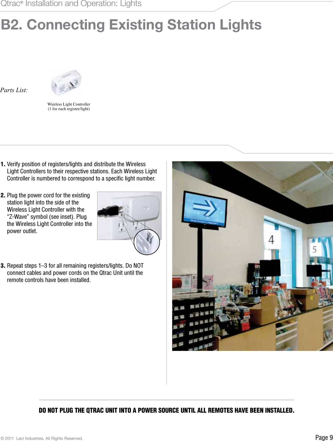
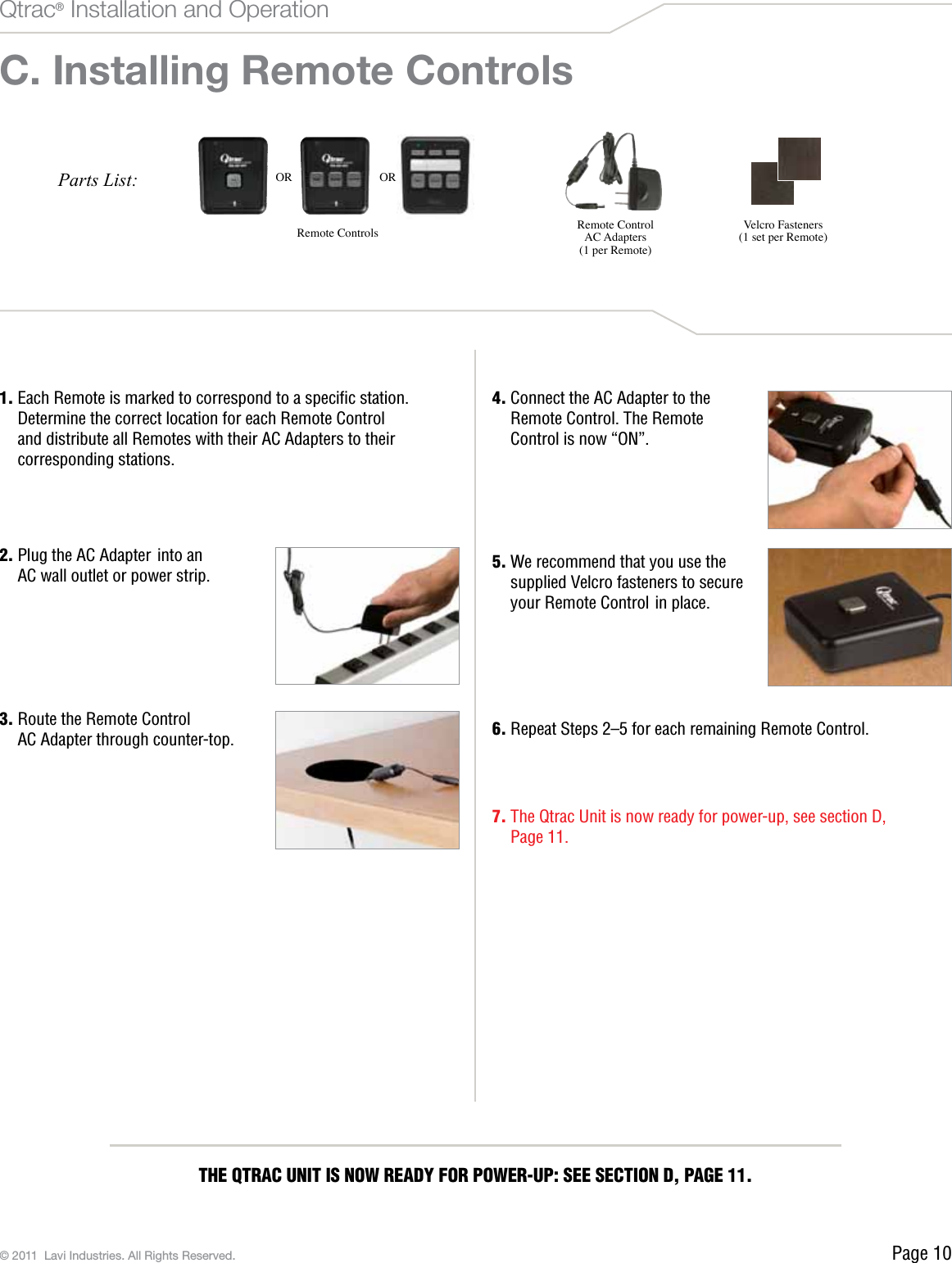
User manual 1 of 2
2.
User manual 2 of 2
User manual 1 of 2
Navigation menu
Upload a User Manual
Namespaces
Wiki Guide
HTML
PDF
Info
Views
User Manual
Discussion / Help
Navigation