Pacific Microwave Research AT100C3 Microwave Video and Audio Transmitter User Manual AT 100C3 User s Manual
Pacific Microwave Research, Inc. Microwave Video and Audio Transmitter AT 100C3 User s Manual
UserManual.wiki
>
Pacific Microwave Research
>
AT100C3 User Manual
>
AT100C3 User Manual
Contents
1.
AT100C3 User Manual
2.
Revised Manual
3.
REV2 Users Manual
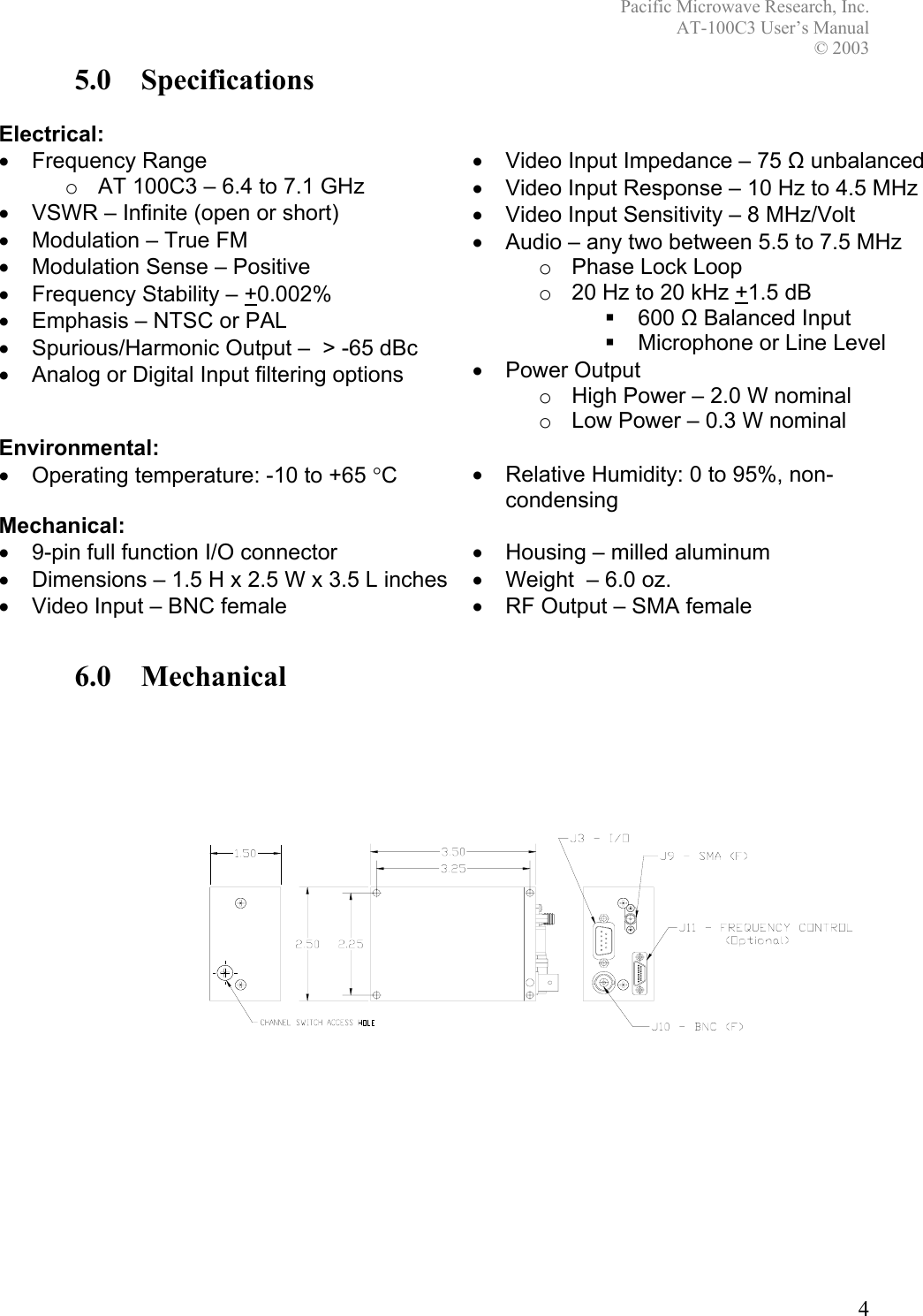
4.
REV 3 Update
5.
Radiation Warning Added
6.
REV 5 User Manual
AT100C3 User Manual
Navigation menu
Upload a User Manual
Namespaces
Wiki Guide
HTML
PDF
Info
Views
User Manual
Discussion / Help
Navigation