ParTech M8936 RFID Reader User Manual EverServ TMD 2 0 User Guide
ParTech Inc. RFID Reader EverServ TMD 2 0 User Guide
UserManual.wiki
>
ParTech
>
M8936 User Manual
>
User Manual
Contents
1.
User Manual
2.
Users Manual
User Manual
Navigation menu
Upload a User Manual
Namespaces
Wiki Guide
HTML
PDF
Info
Views
User Manual
Discussion / Help
Navigation
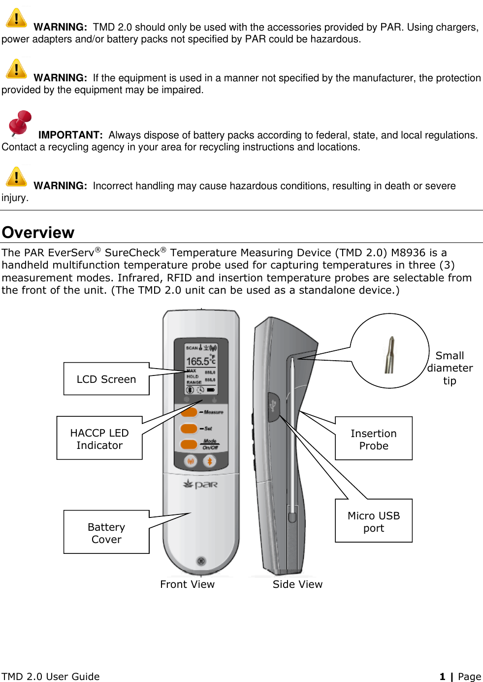
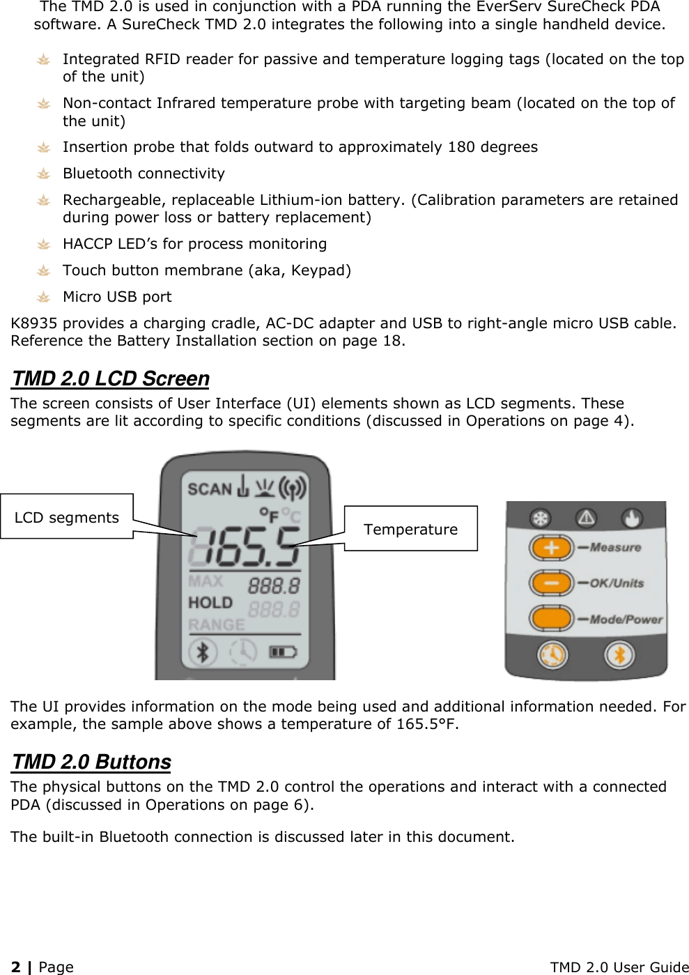
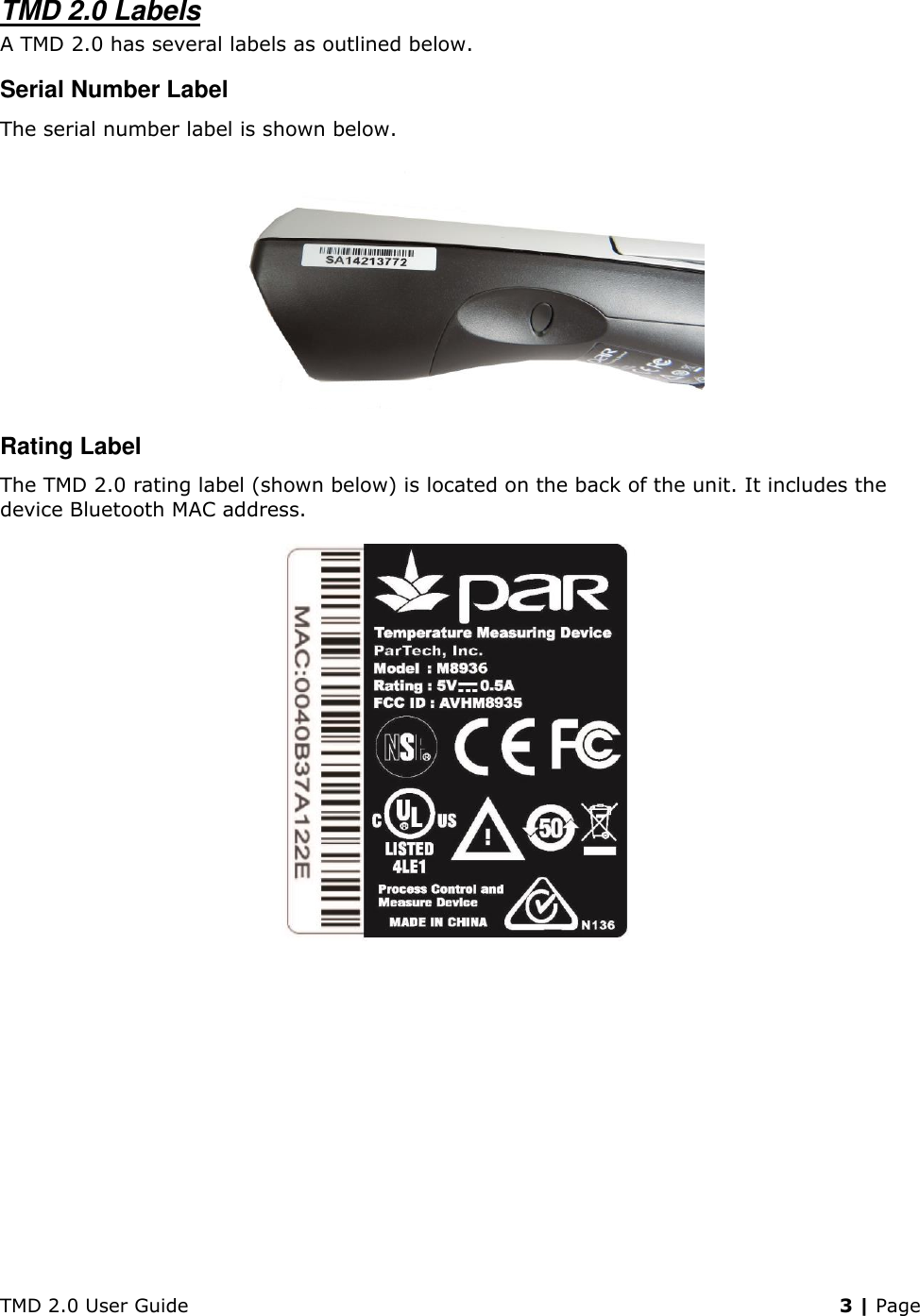
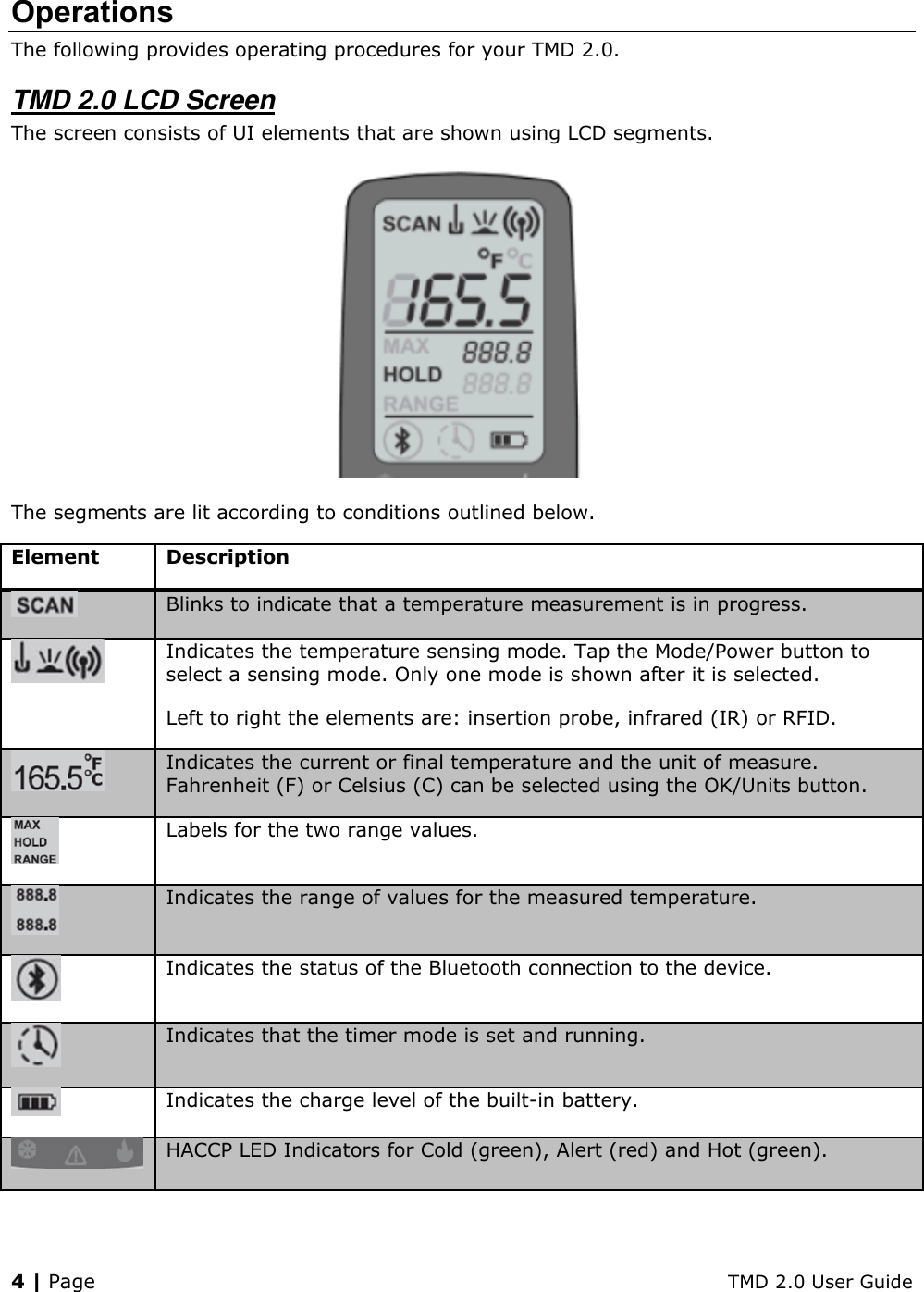
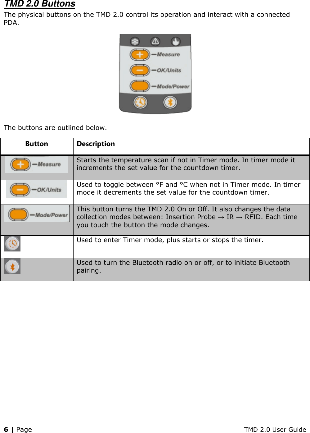
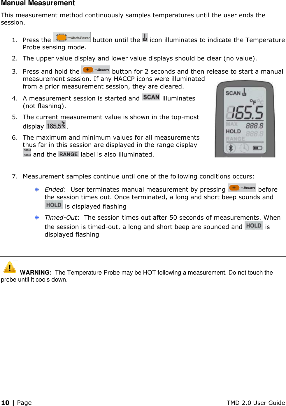
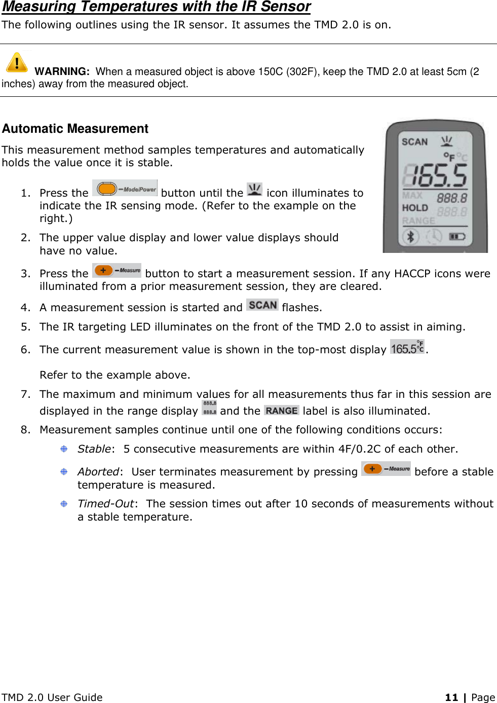
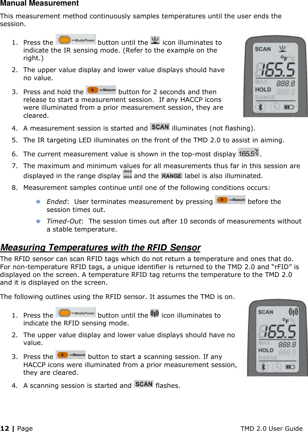
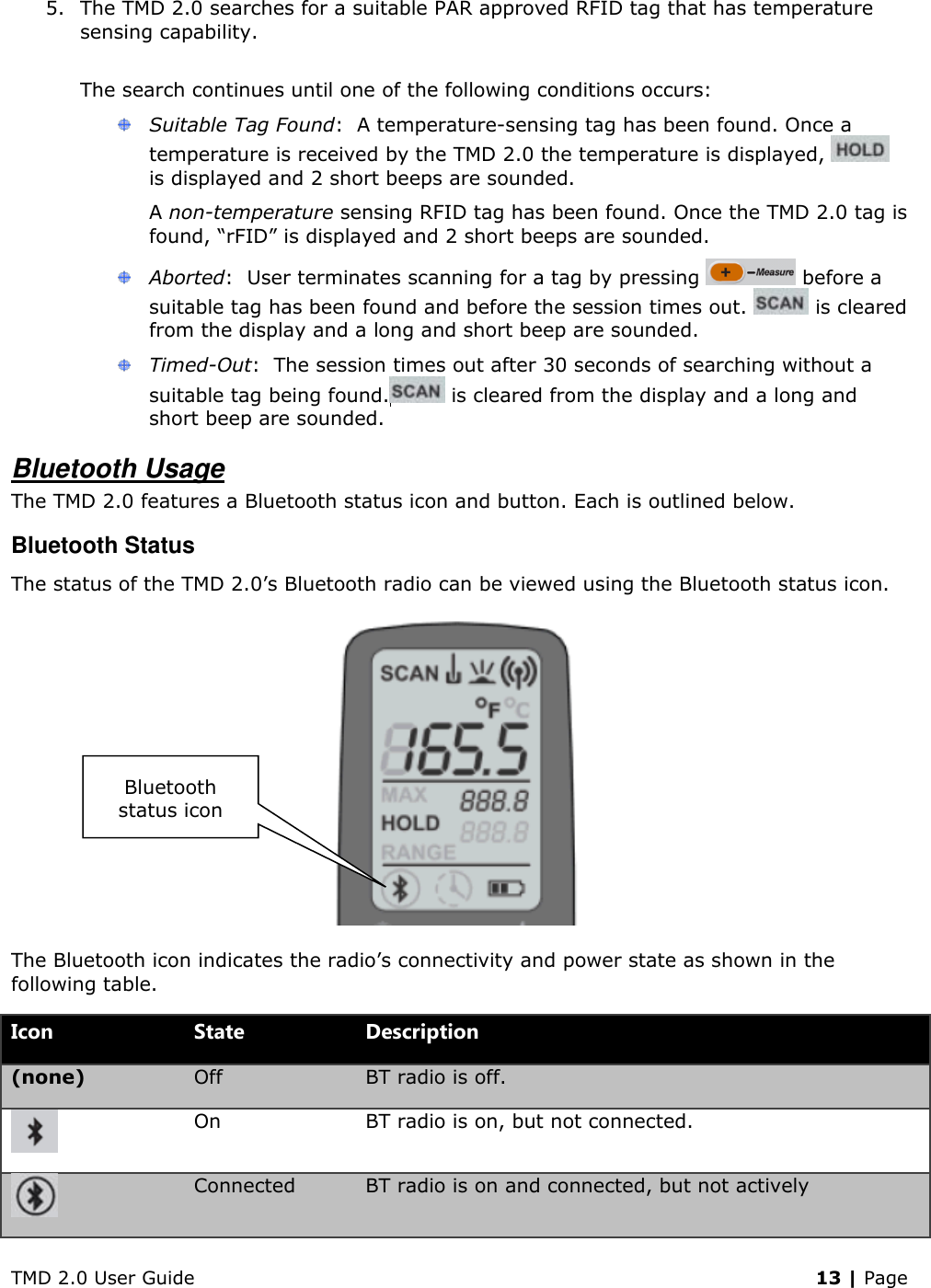


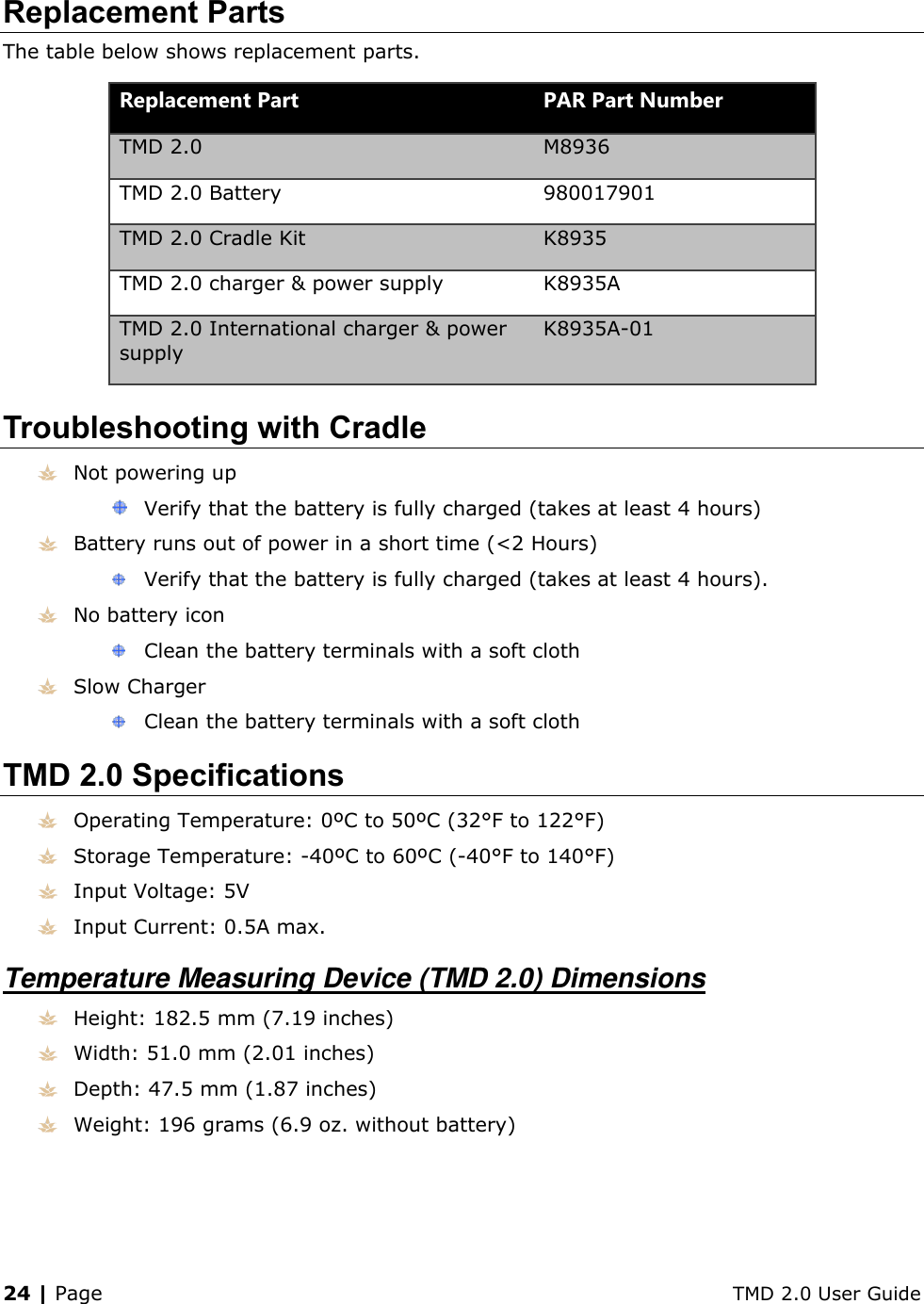
![TMD 2.0 User Guide 25 | Page Thermo Couple Type T Based Insertion Probe Temperature range: -40°C to 300°C (-40°F to 572°F) Accuracy: -40°C to 300°C (-40°F to 572°F) = Measured Temp ± 0.5°C or 0.4% Probe: approximate 4” usable insertion depth. Folds back into hand grip for storage when not in use Infrared Temperature Probe Temperature range: -40°C to 300°C (-40°F to 572°F) Accuracy: 0°C to 65°C (32°F - 150°F) = Measured Temp ±1 °C (± 2 °F) < 0°C (32°F) = Measured Temp ± 1°C (± 2°F) + 0.1 degree per degree Formula:[=Measured Temp ± │(1°C or 2°F) +(Measured Temp * 0.1)│] >65°C (150 °F) = Measured Temp ± (Measured Temp *1.5%) Optimal scanning distance: 2 inches or less IR sensor: detects surface temperatures and target beam visible on surfaces within approximately five (5) inches RFID 13.56 MHz operating frequency 10 mm typical range for passive tags, 30 mm for self-energized tags Compliant to NFCIP-1 (ISP 18092) and NFCIP-2 Bluetooth Connectivity Ability to interface with outside devices via Bluetooth Supports Bluetooth low energy 4.0 capability Micro USB Port Used for charging the battery pack. Micro USB charging cable required, PAR P/N 980017903 Power Options Lithium Ion Battery, requires initial charging of approximately 4 hours Rechargeable battery pack, PN980017903 LCD Screen Backlight: White LED](https://usermanual.wiki/ParTech/M8936.User-Manual/User-Guide-2403130-Page-29.png)