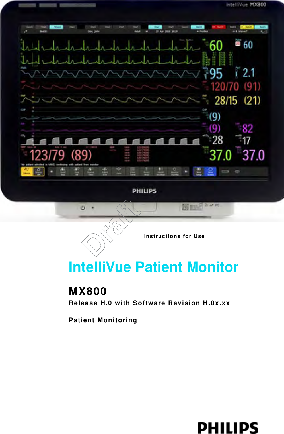
Philips Medical Systems North America SRRBV2 Single Short Range Radio Module User Manual
Philips Medical Systems North America Co. Single Short Range Radio Module
UserManual.wiki
>
Philips Medical Systems North America
>
SRRBV2 User Manual
>
User Manual Olympus
Contents
1.
User Manual Olympus
2.
User Manual Saturn
User Manual Olympus
Navigation menu
Upload a User Manual
Namespaces
Wiki Guide
HTML
PDF
Info
Views
User Manual
Discussion / Help
Navigation

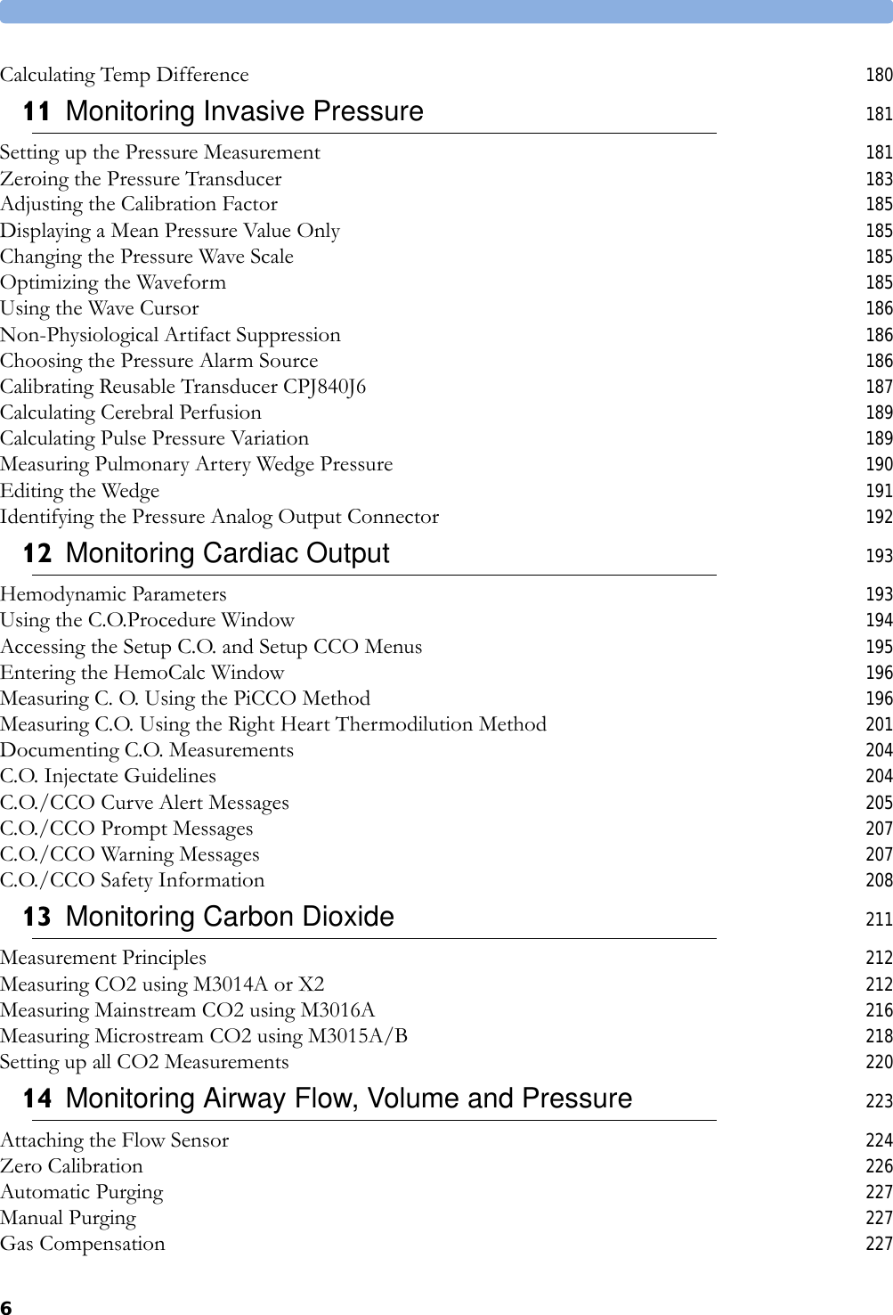

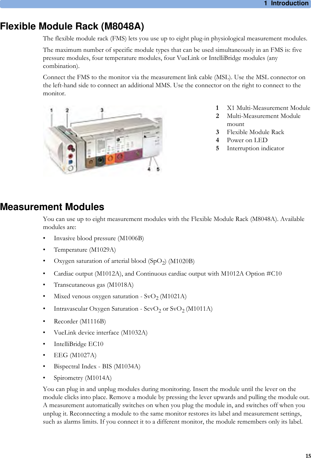
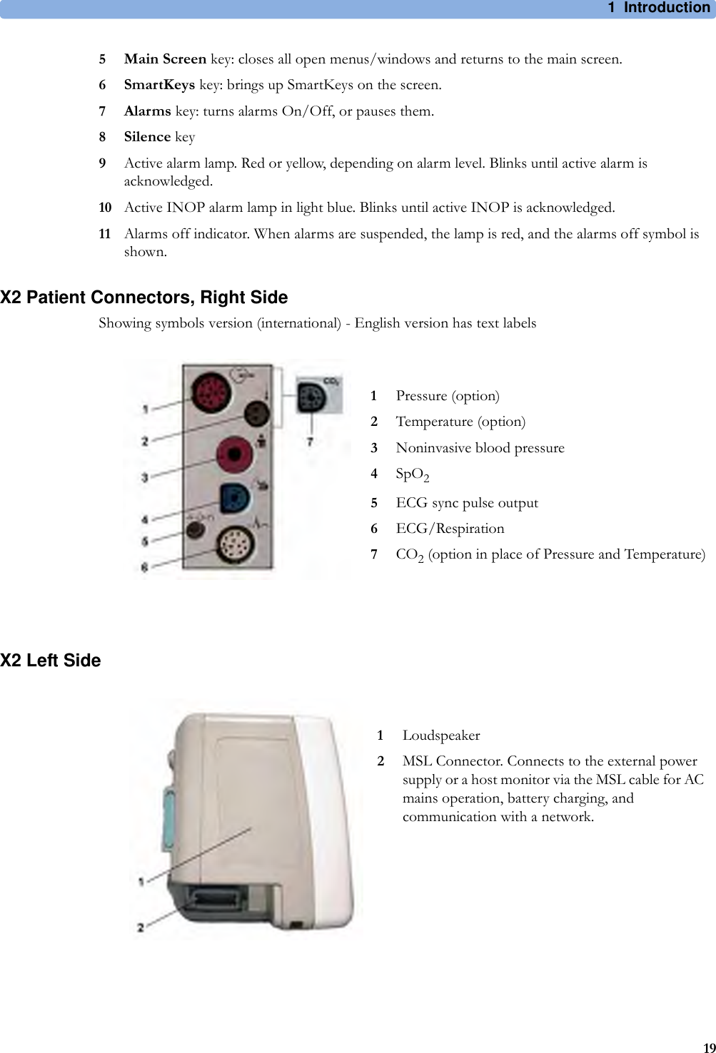


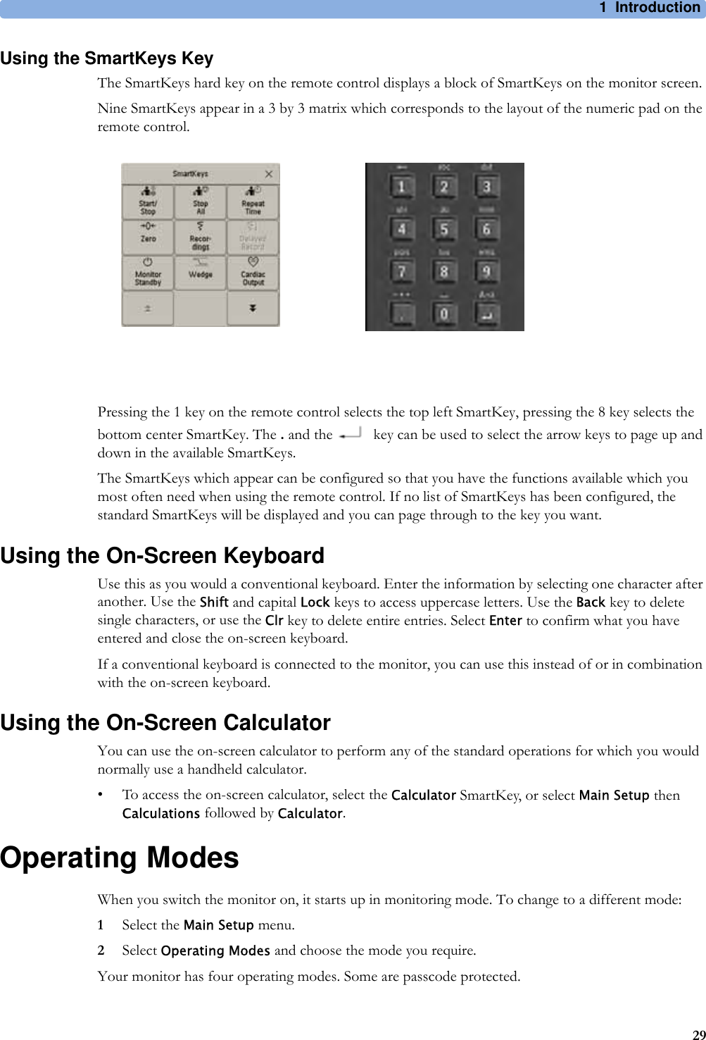
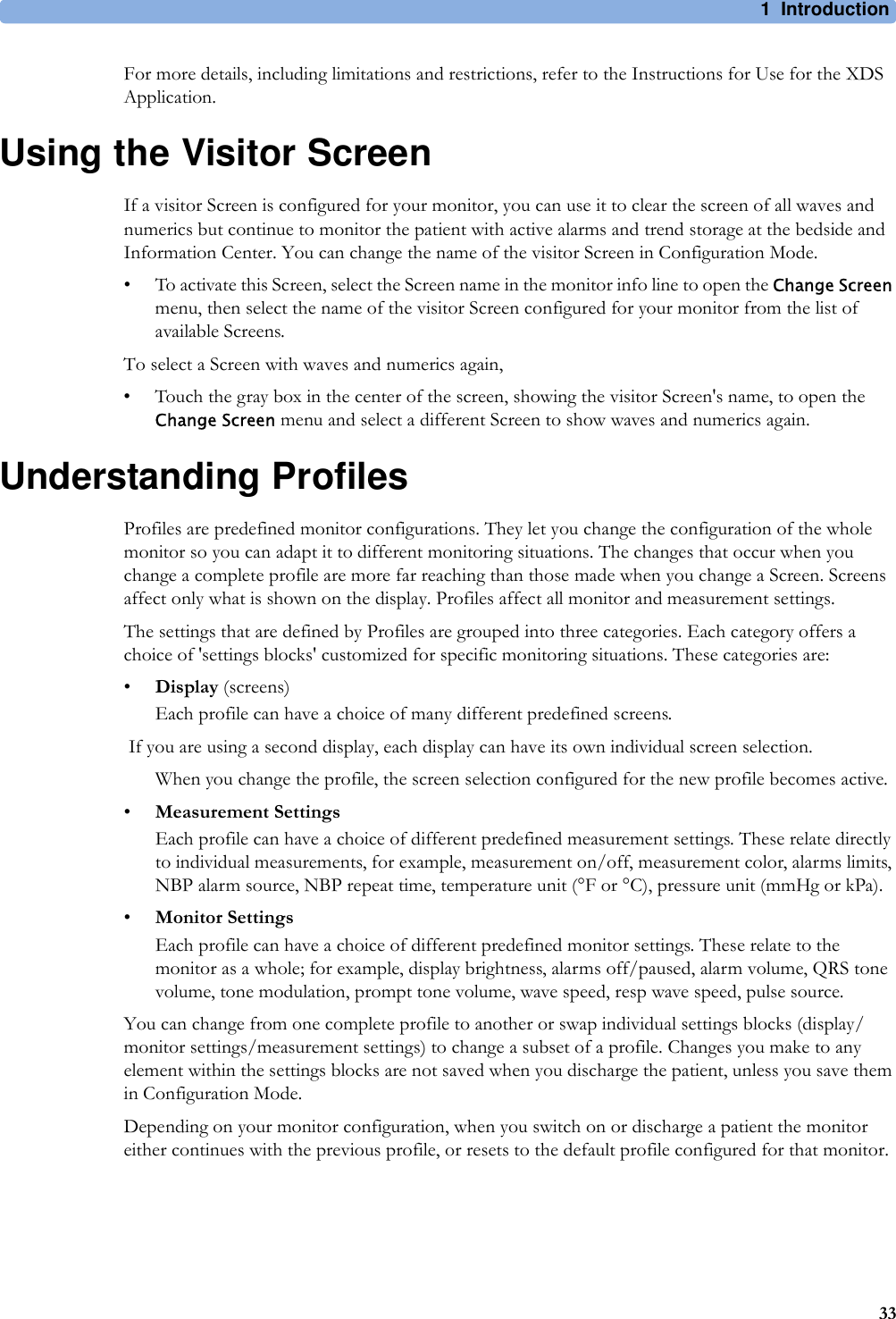

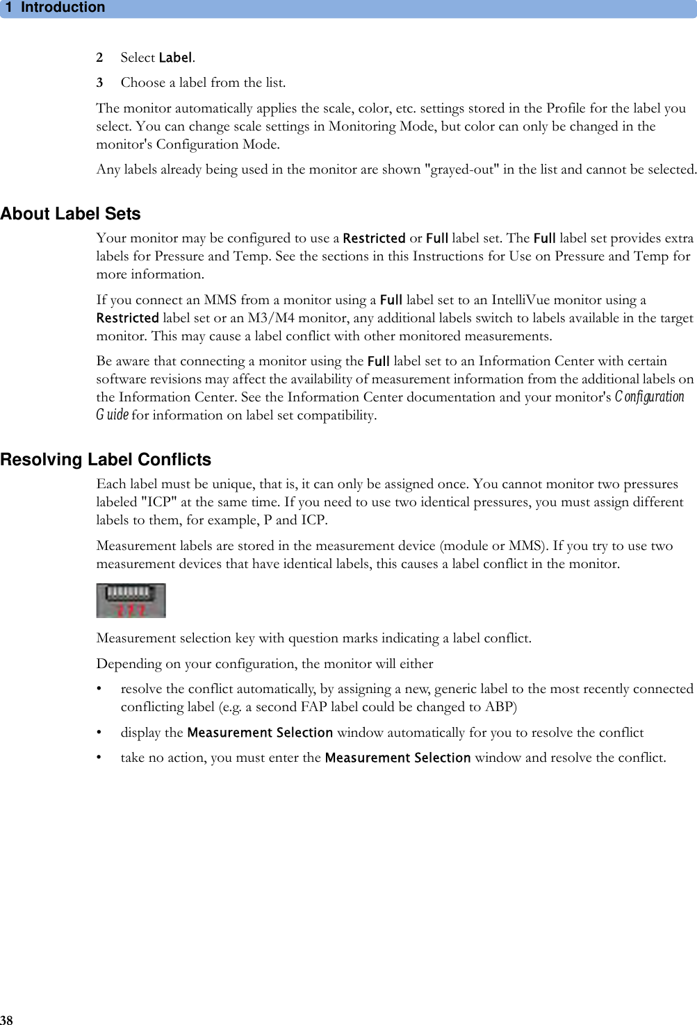
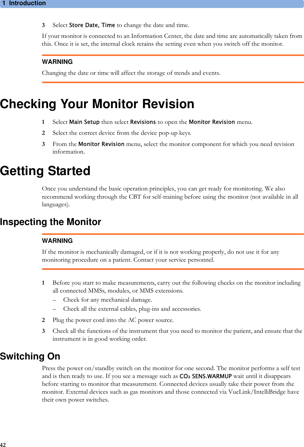
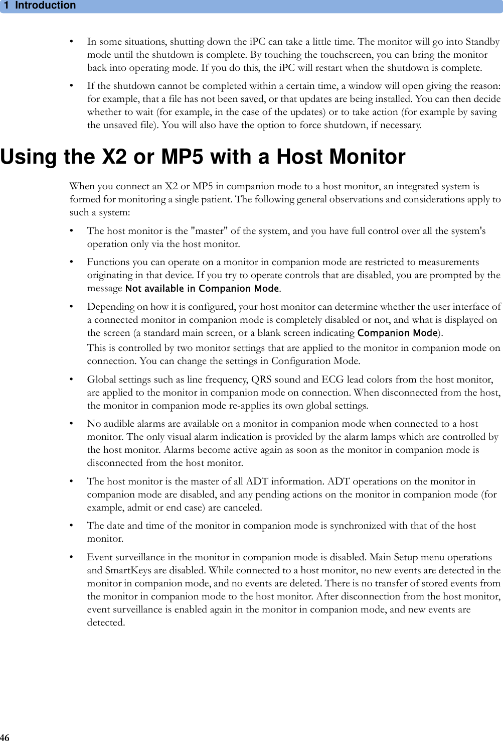
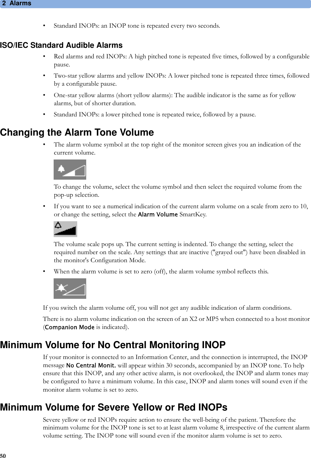
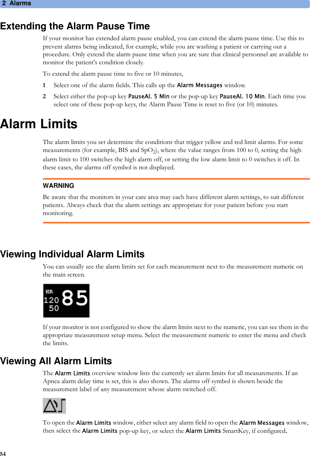
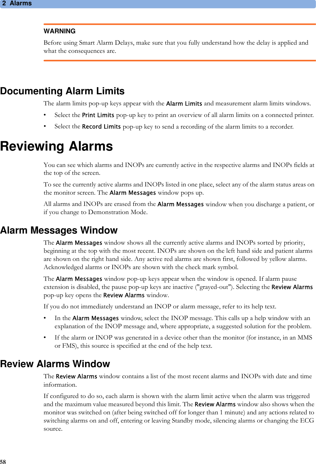

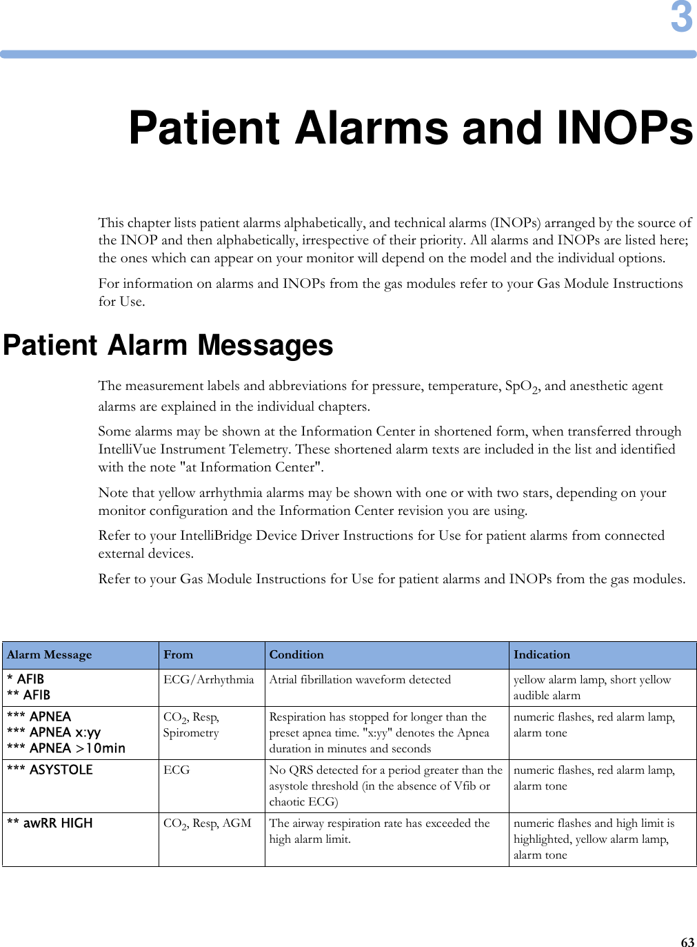
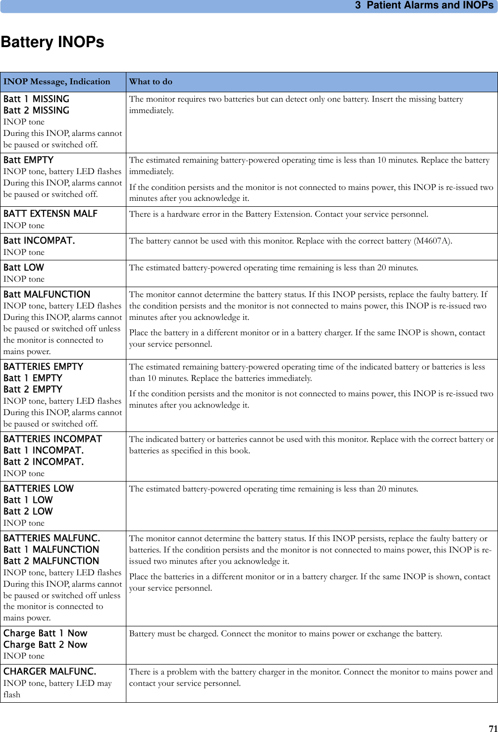
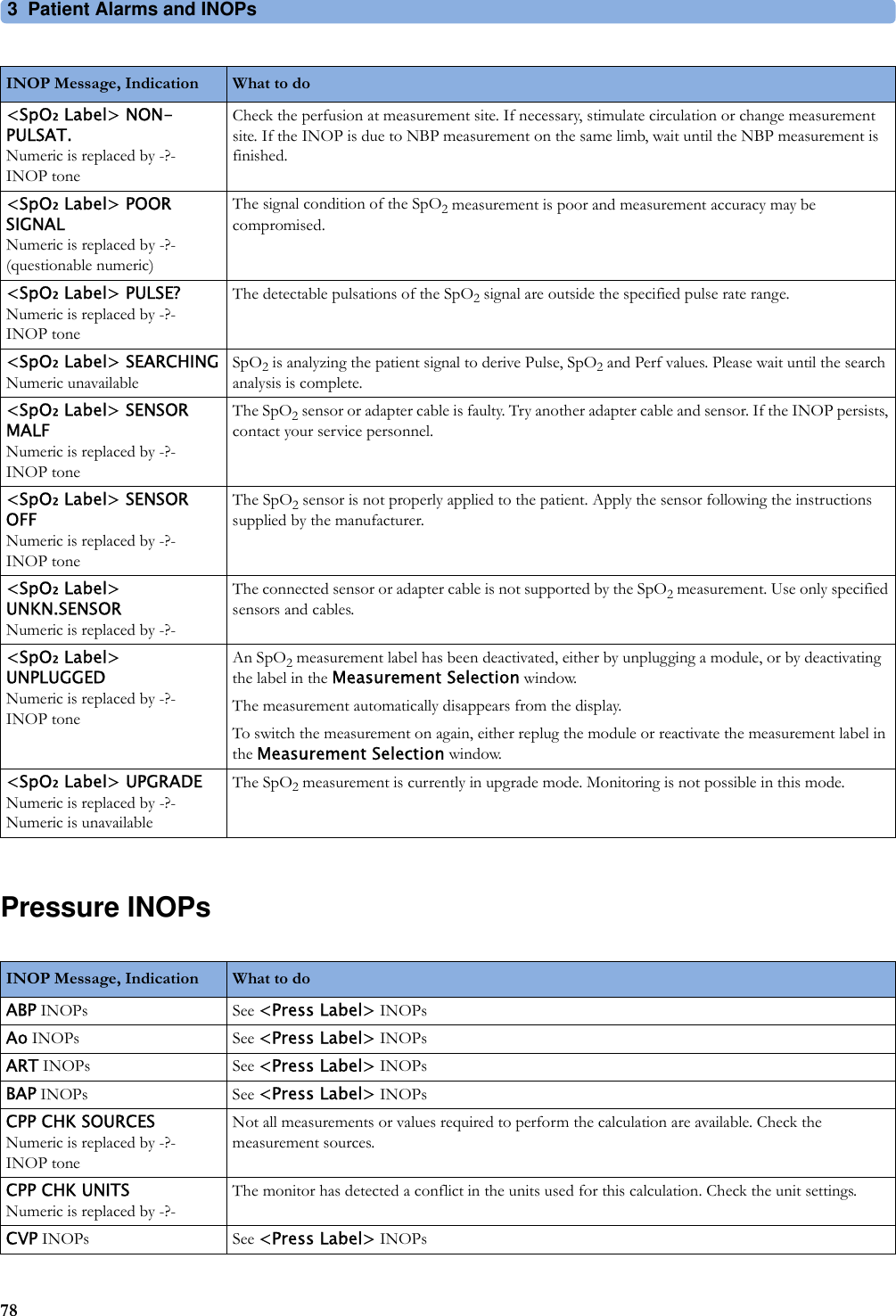
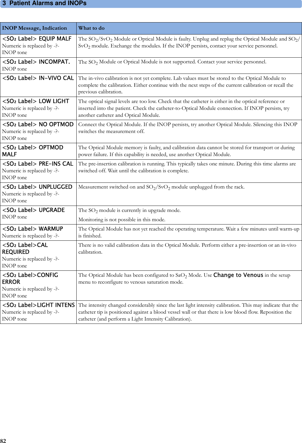
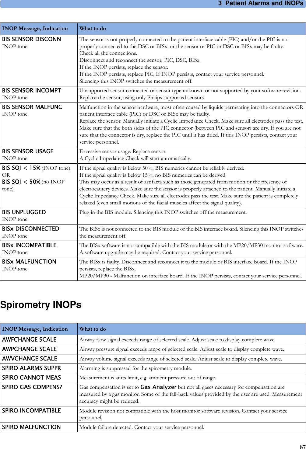
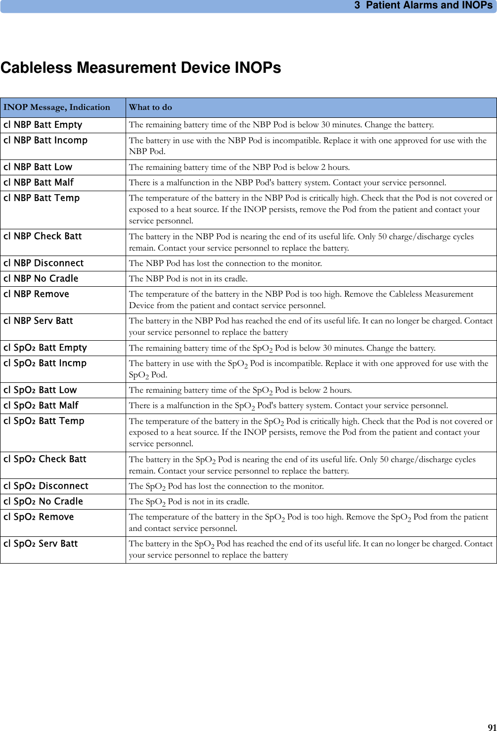
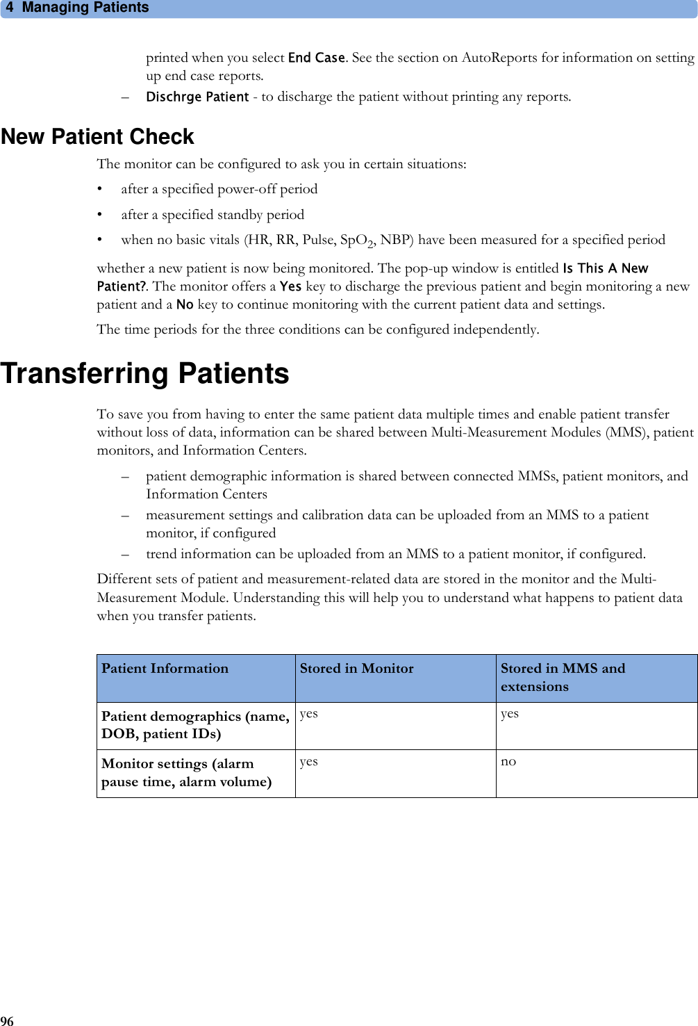
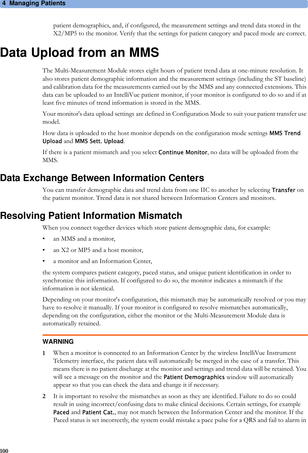
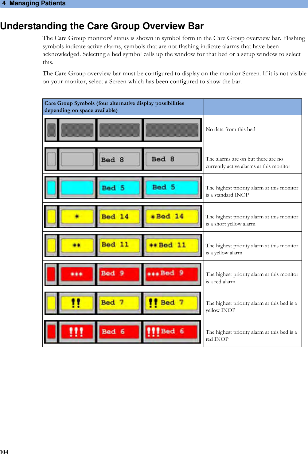
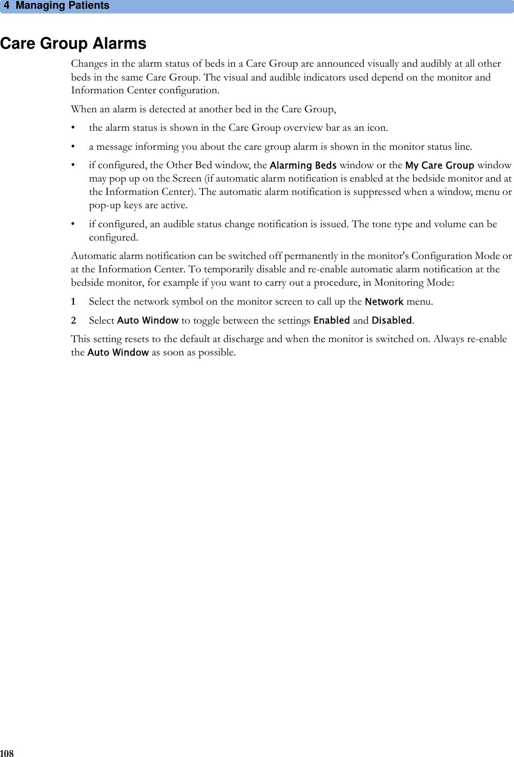
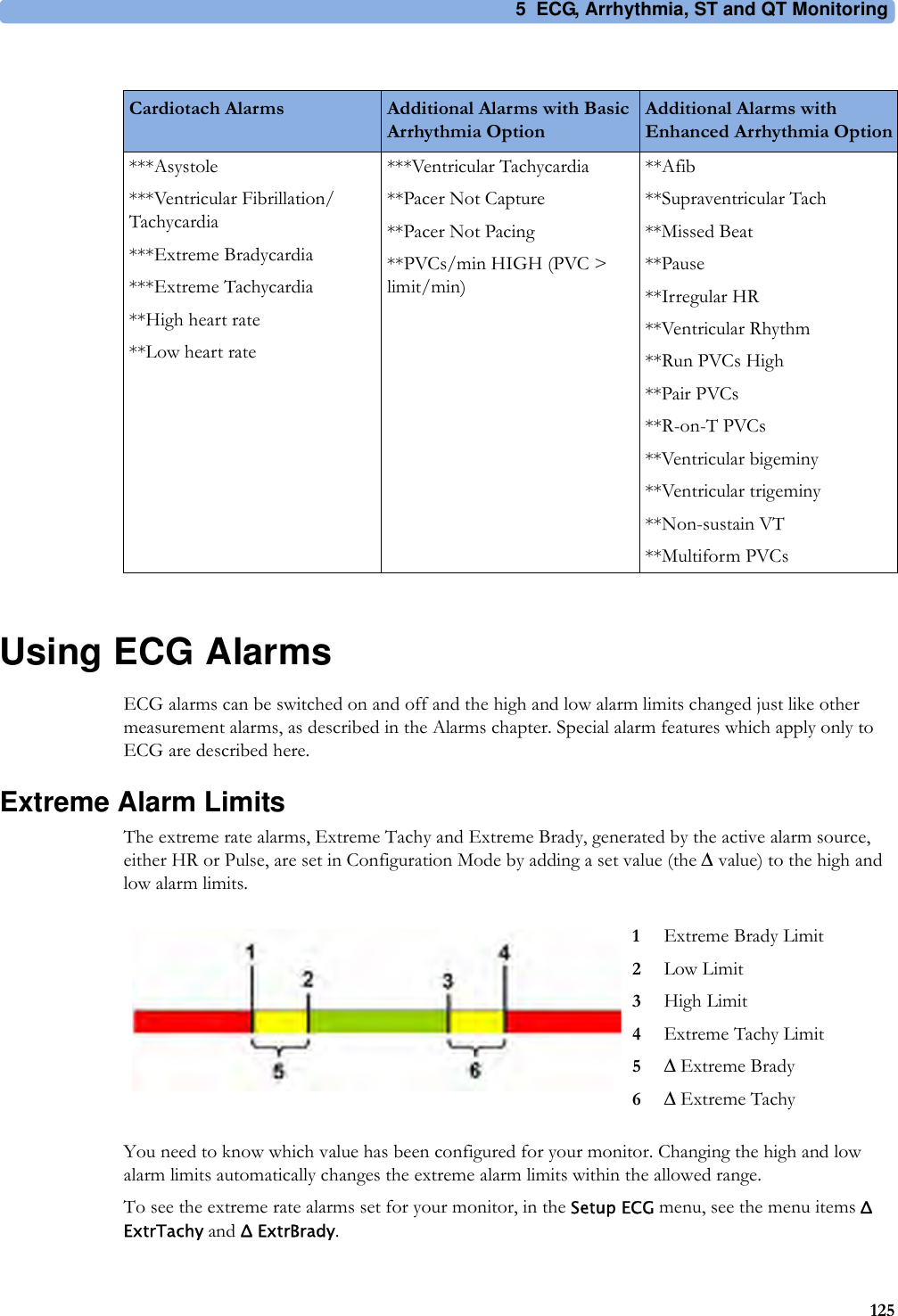
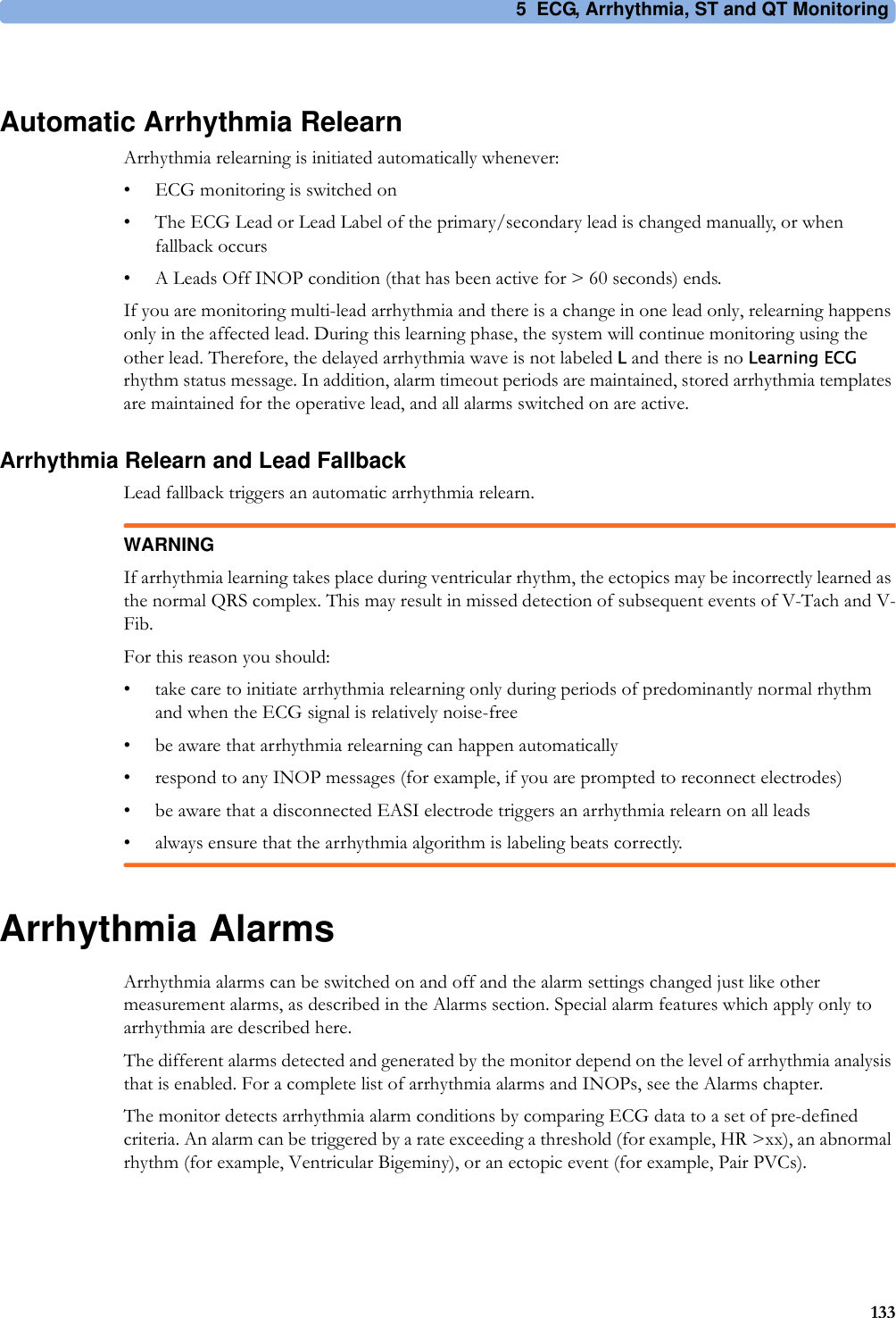
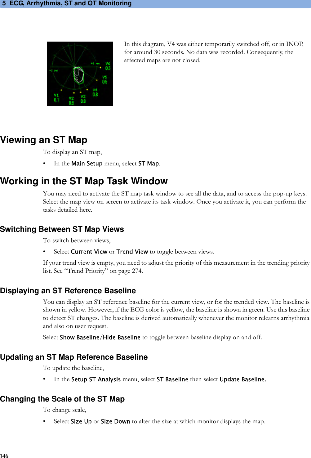
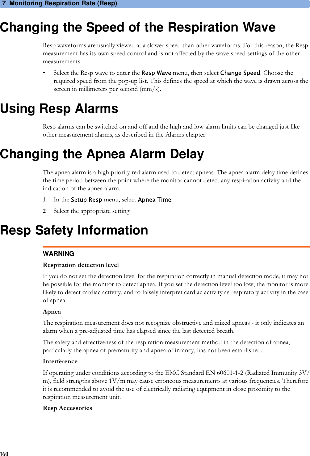
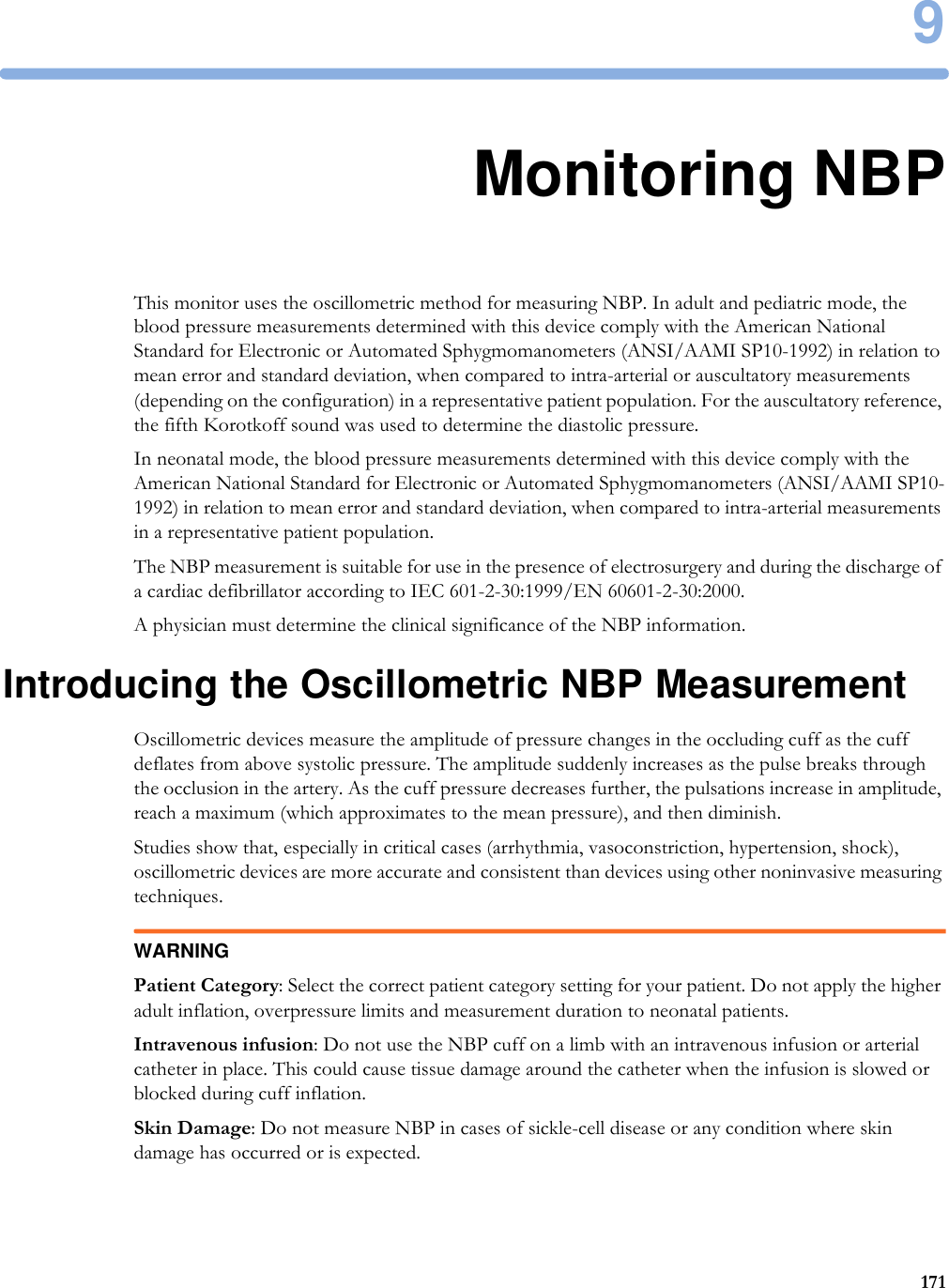
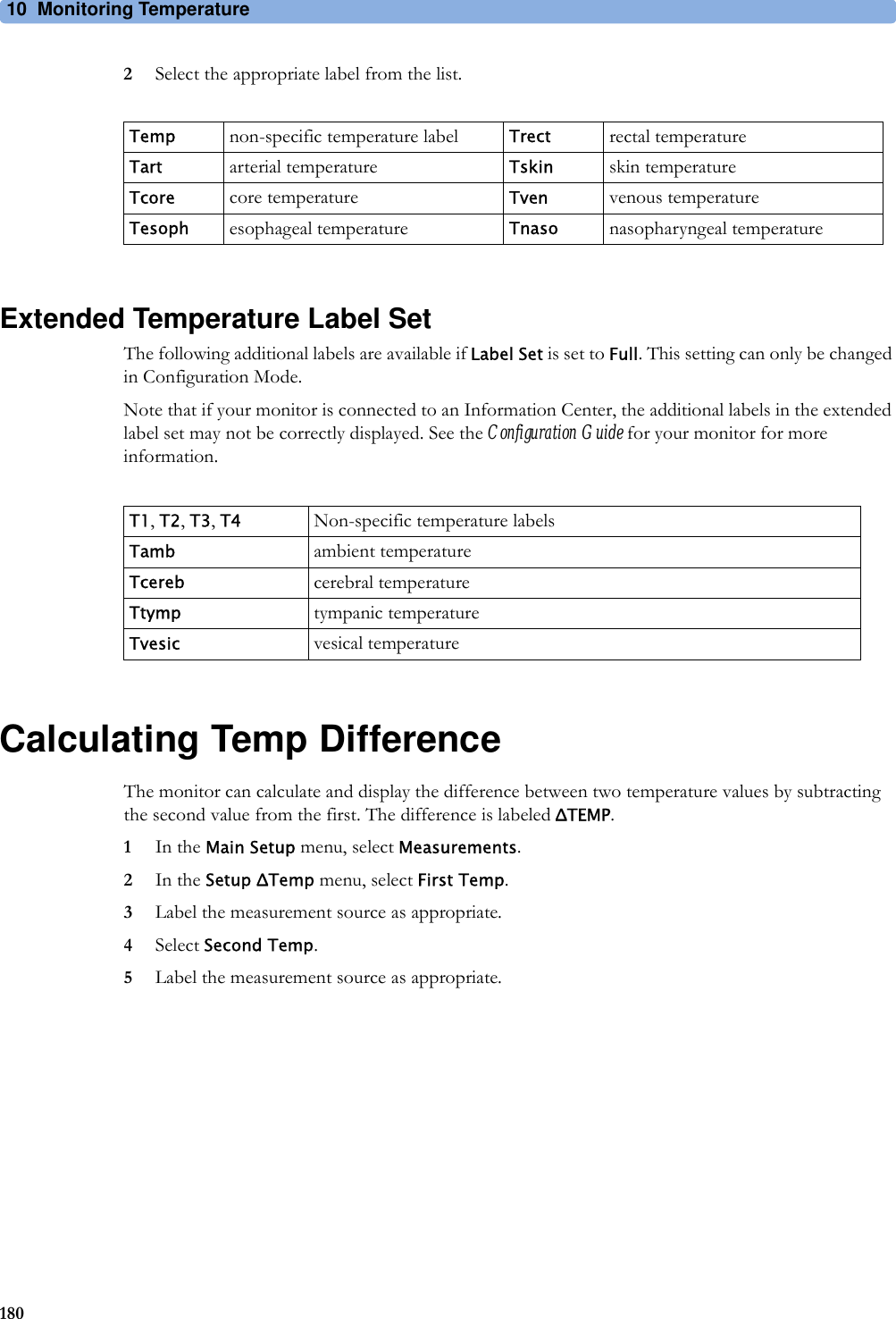
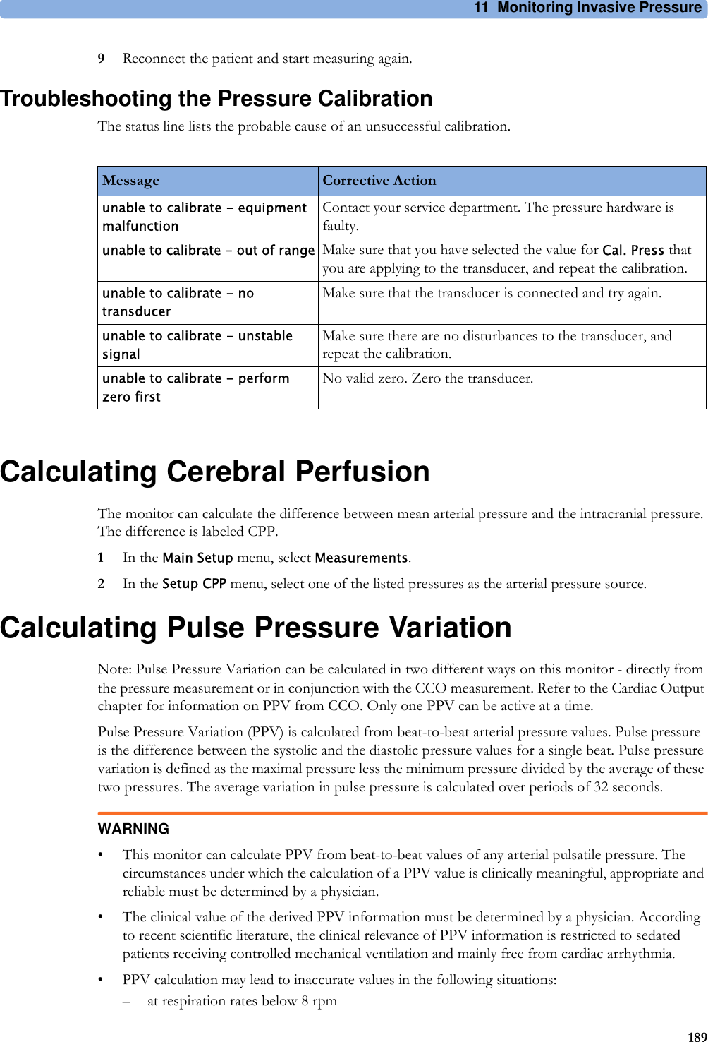
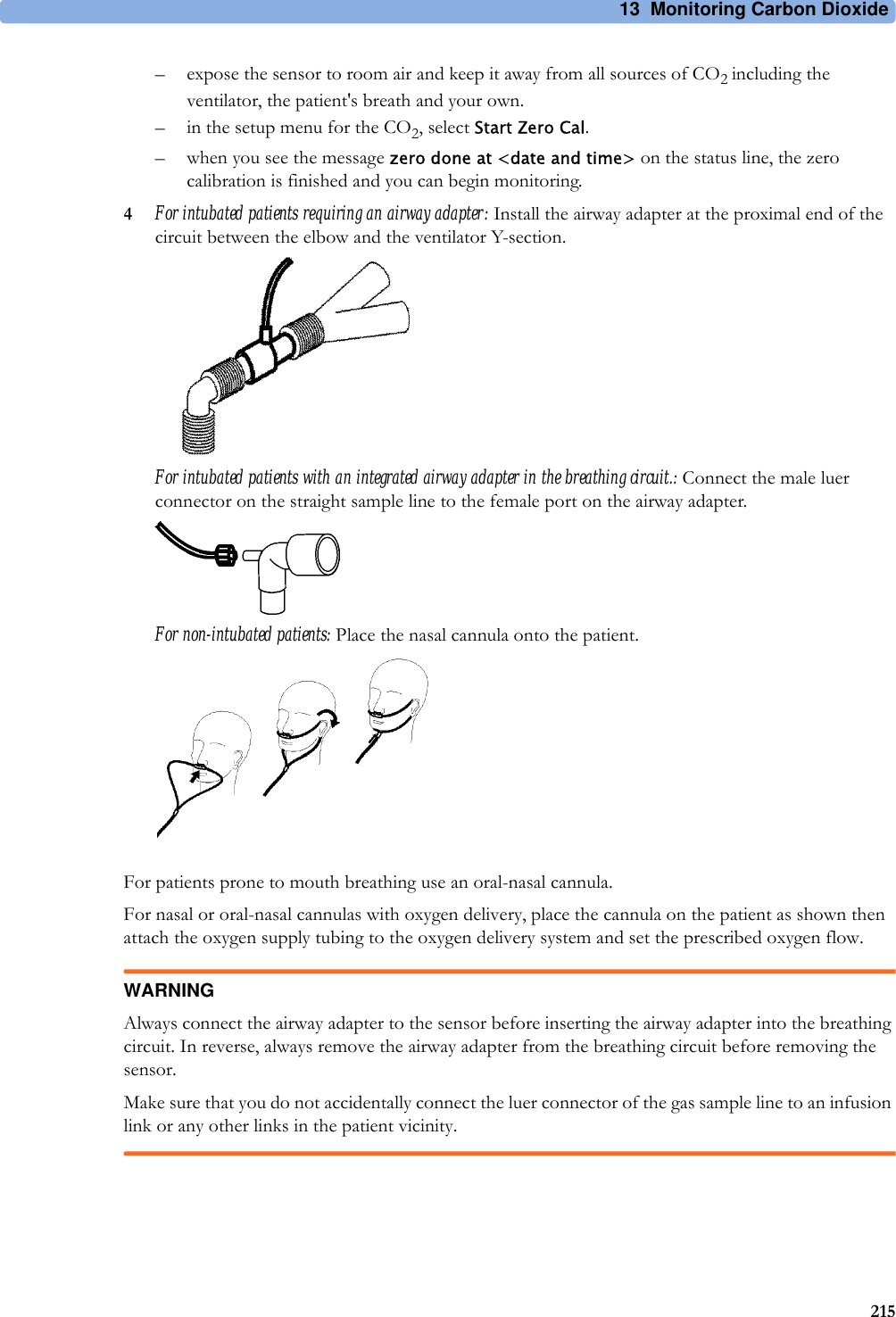
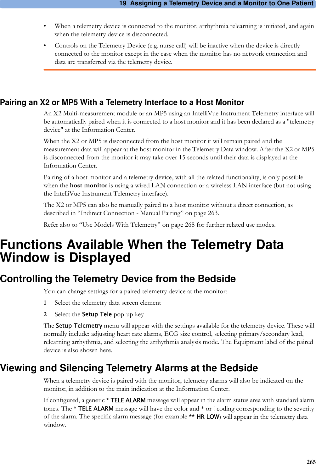
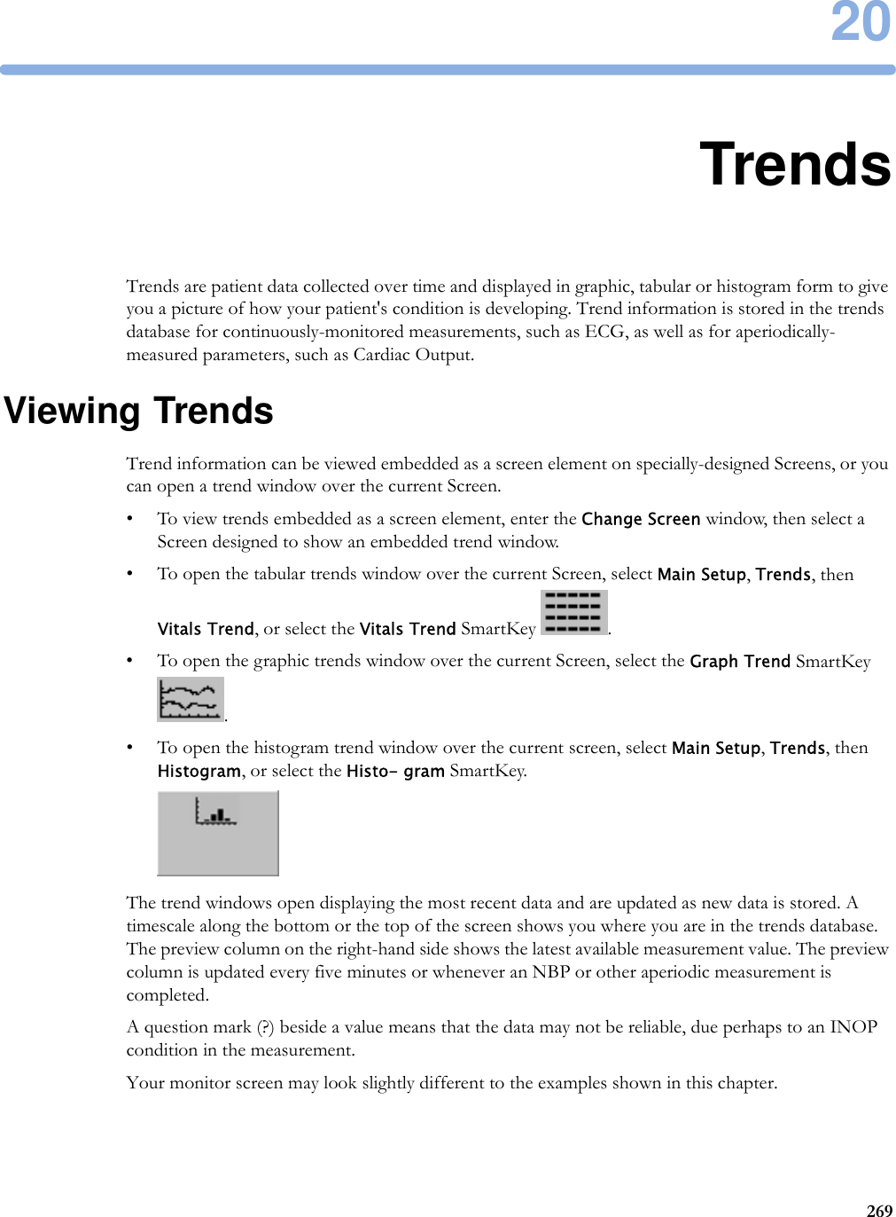
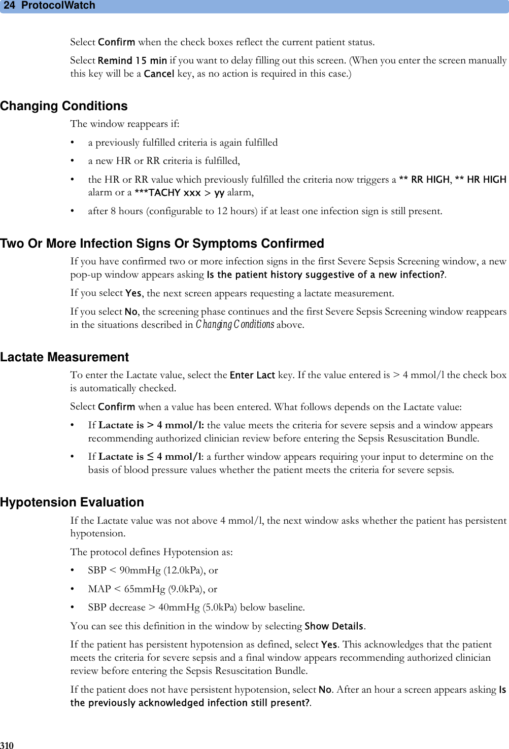
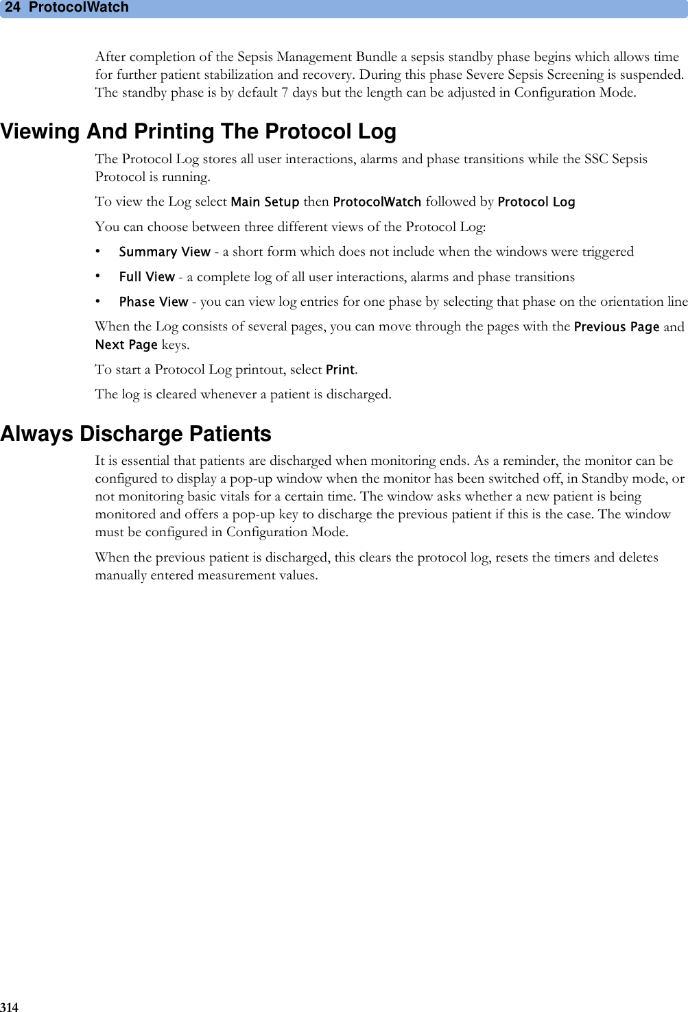
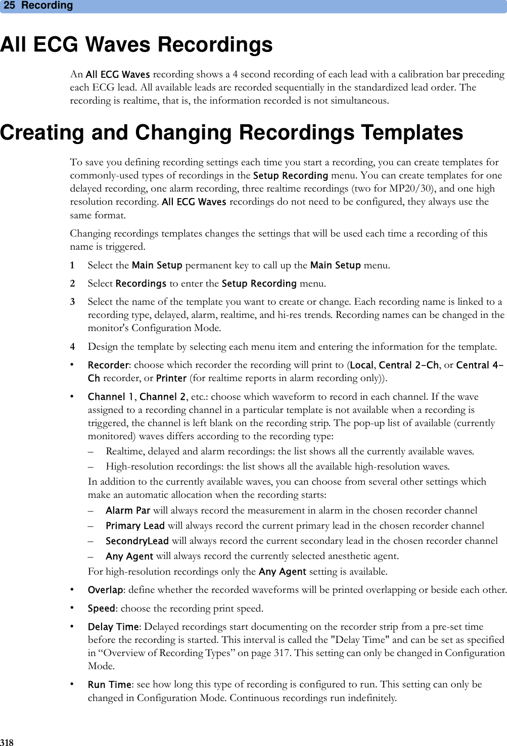
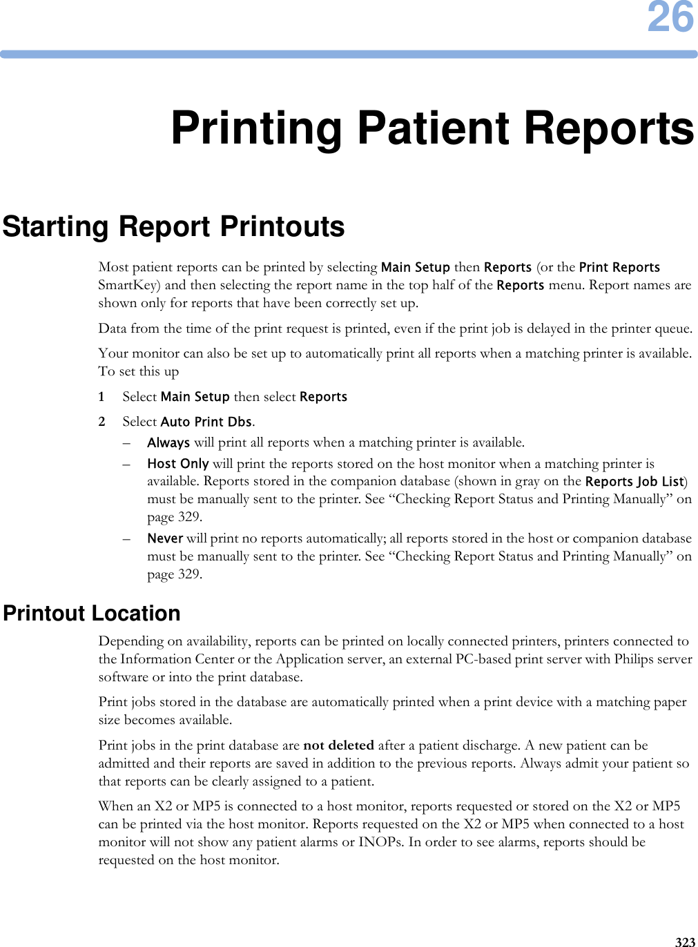
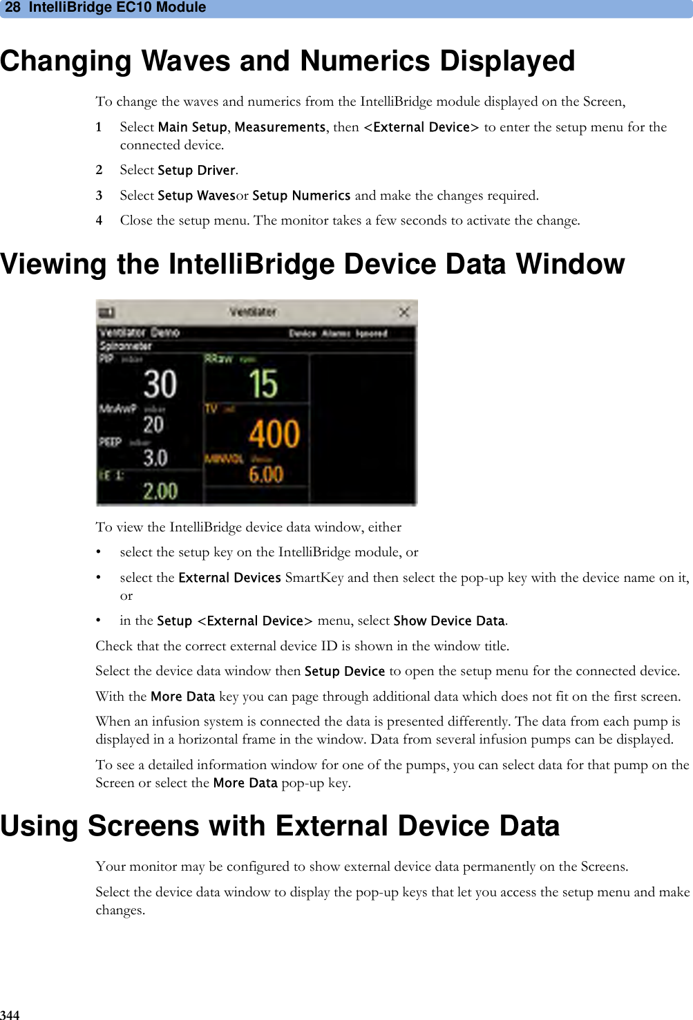
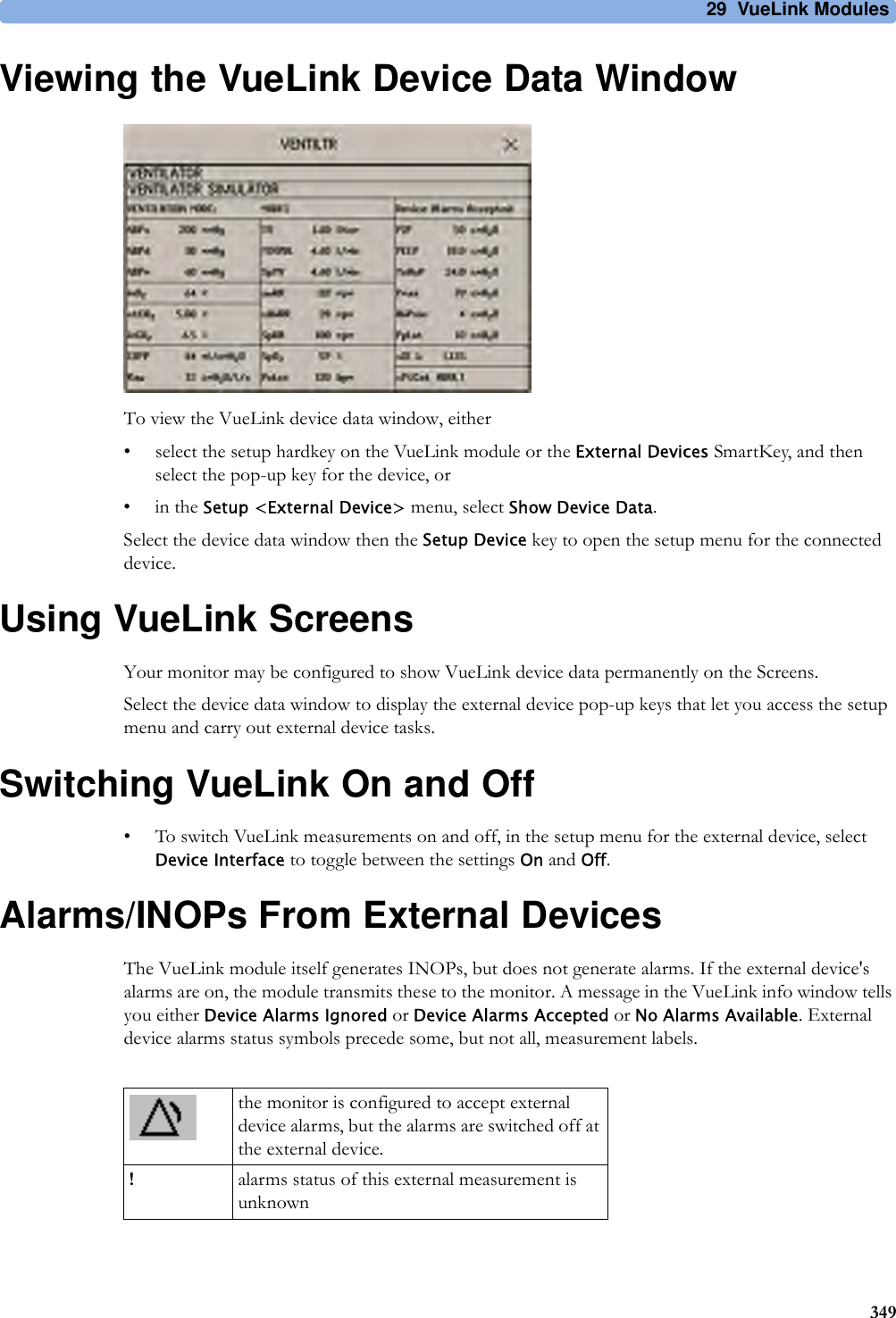
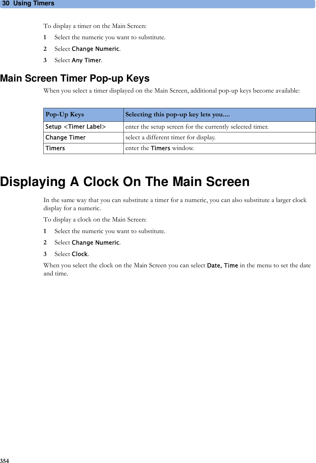
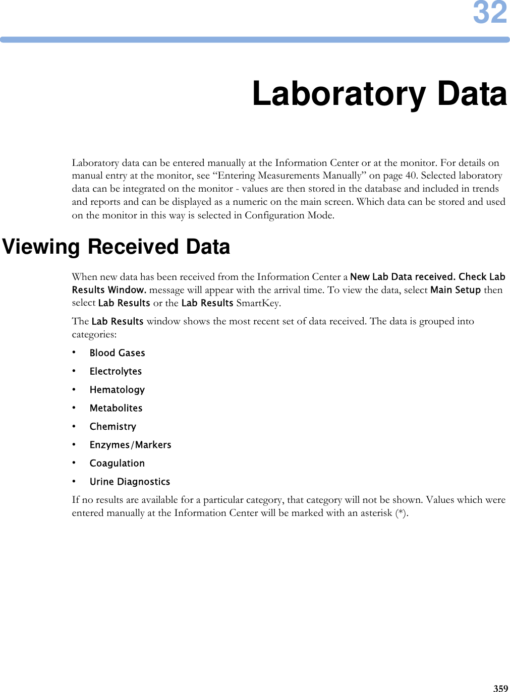
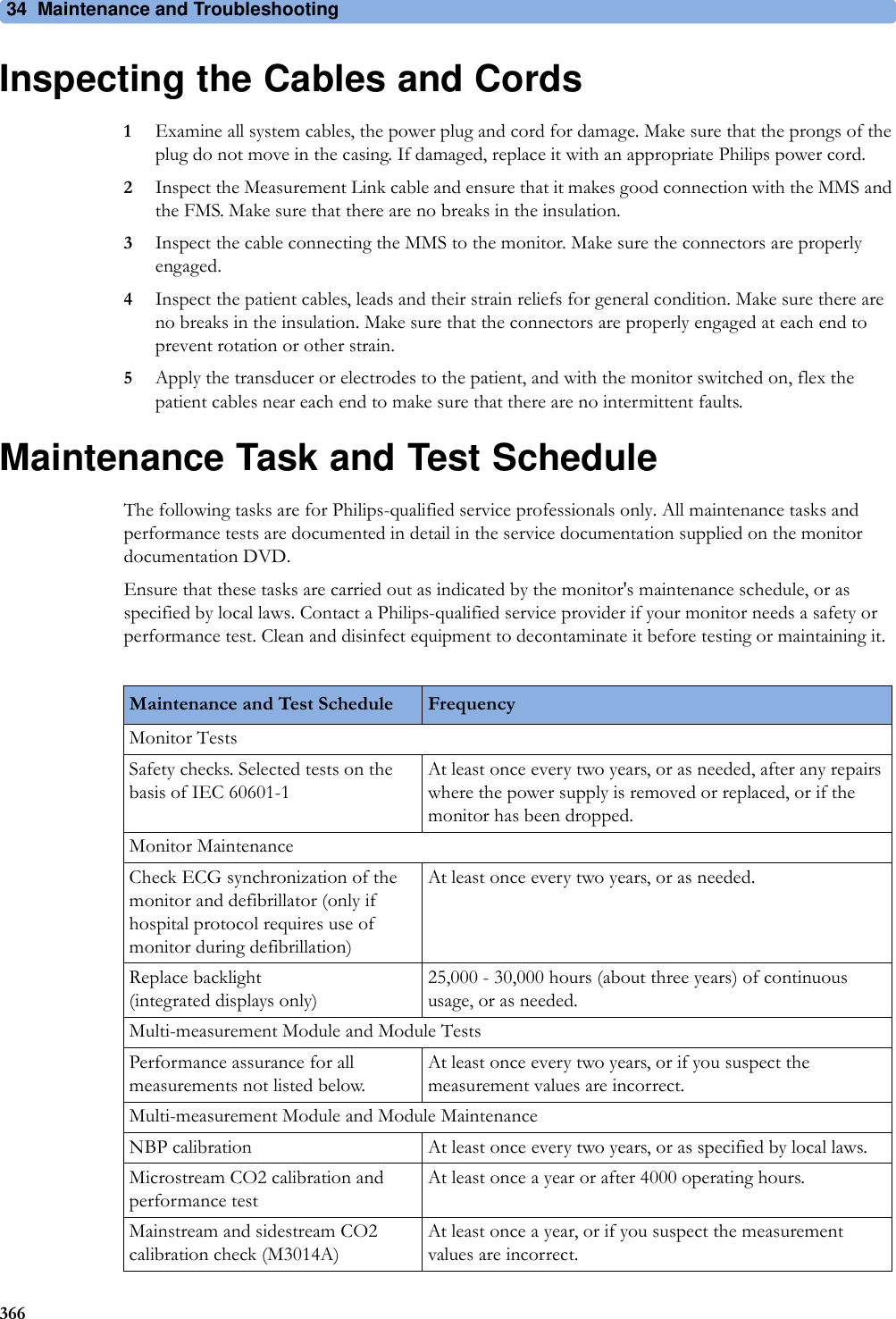
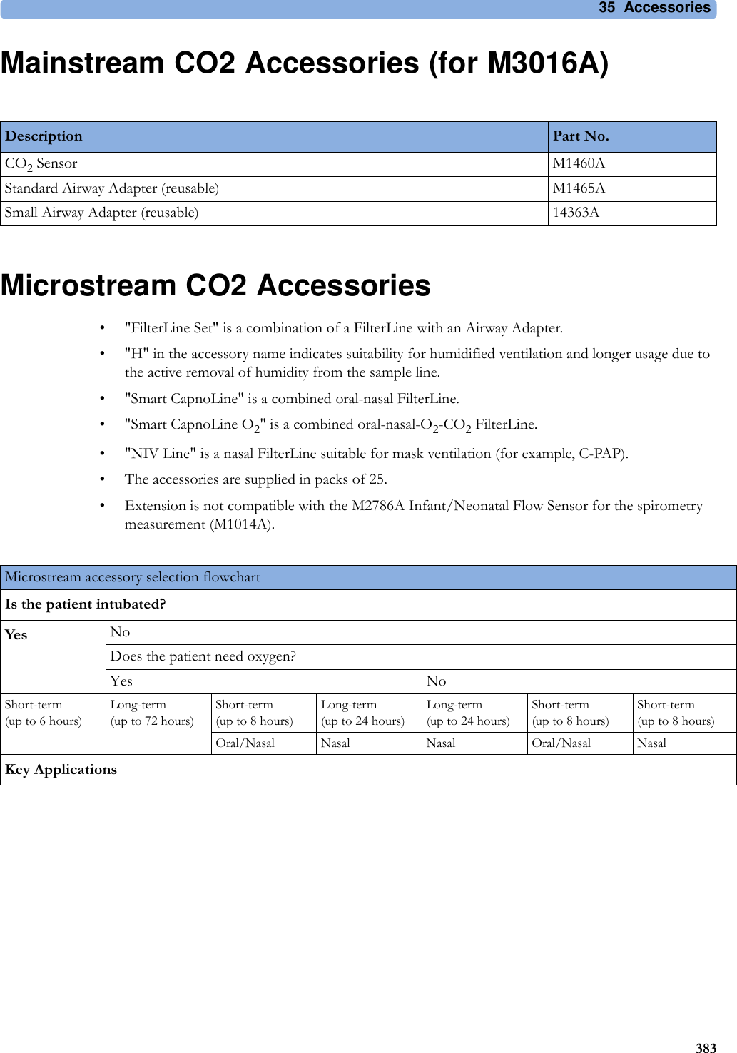
![3 Patient Alarms and INOPs74CANNOT ANALYZE ST The ST algorithm cannot generate a valid ST value. Possible causes are large variations in the measured ST values for consecutive beats, or ventricular paced beats. Review the ECG signal quality and the ST measurement points. If the patient has a ventricular pacemaker, ST analysis is not possible.ECG EL. NOISY <ECG Lead>The ECG signal from the named ECG electrodes [RA, LA, LL, RL, V (or C)] is noisy. Check the ECG connections and make sure that the electrode indicated is attached.ECG EQUIP MALFNumeric is replaced by -?-INOP toneContact your service personnel.The ECG hardware is faulty.<ECG Lead> LEAD OFF!! <ECG Lead> LEAD OFF!!! <ECG Lead> LEAD OFFNumeric is replaced by -?-INOP toneNot all the required leads for ECG monitoring are connected. Check the ECG connections and make sure that the electrode indicated by <ECG lead> [RA, LA, LL, RL, V or C] electrodes is attached. In EASI mode, all 5 electrodes must be connected.ECG LEADS OFF!! ECG LEADS OFF!!!ECG LEADS OFFCheck that all of the required ECG leads are attached, and that none of the electrodes have been displaced.ECG NOISY SIGNALINOP toneThe ECG signal is too noisy. Check that the electrodes are properly placed and have not dried out. Remove any possible sources of signal noise (such as power cords) from the area around the cable and the patient.The ECG signal may be saturated or overloaded.!!ECG/AR ALARM OFF All ECG alarms have been switched off, or the HR alarm source is not ECG. To resume ECG alarm generation, switch ECG alarms on or select ECG as the alarm source.ECG/ARRH ALARM OFF!!ECG/AR ALARM OFFAll ECG alarms have been switched off, or the HR alarm source is not ECG. To resume ECG alarm generation, switch ECG alarms on or select ECG as the alarm source.EcgOut EQUIP MALFINOP toneThere is a problem with the device connected to the ECG Out connector. Contact your service personnel.LA LEAD OFFNumeric is replaced by -?- for 10 seconds.INOP toneThe LA electrode has become detached from the patient or the lead set has been changed. Reattach the electrode or select New Lead Setup in the Setup ECG menu to confirm the new lead set.LL LEAD OFFNumeric is replaced by -?- for 10 seconds.INOP toneThe LL electrode has become detached from the patient or the lead set has been changed. Reattach the electrode or select New Lead Setup in the Setup ECG menu to confirm the new lead set.RA LEAD OFFNumeric is replaced by -?-INOP toneThe RA electrode has become detached from the patient or the lead set has been changed. Reattach the electrode or select New Lead Setup in the Setup ECG menu to confirm the new lead set.RL LEAD OFFNumeric is replaced by -?- for 10 seconds.INOP toneThe RL electrode has become detached from the patient or the lead set has been changed. Reattach the electrode or select New Lead Setup in the Setup ECG menu to confirm the new lead set.SOME ECG ALRMS OFF This message appears (if configured to do so) when the on/off settings of the yellow arrhythmia alarms differ from the current Profile.V LEAD OFFNumeric is replaced by -?- for 10 seconds.INOP toneThe V electrode (IEC: C electrode) has become detached from the patient or the lead set has been changed. Reattach the electrode or select New Lead Setup in the Setup ECG menu to confirm the new lead set.INOP Message, Indication What to do](https://usermanual.wiki/Philips-Medical-Systems-North-America/SRRBV2.User-Manual-Olympus/User-Guide-1340937-Page-74.png)
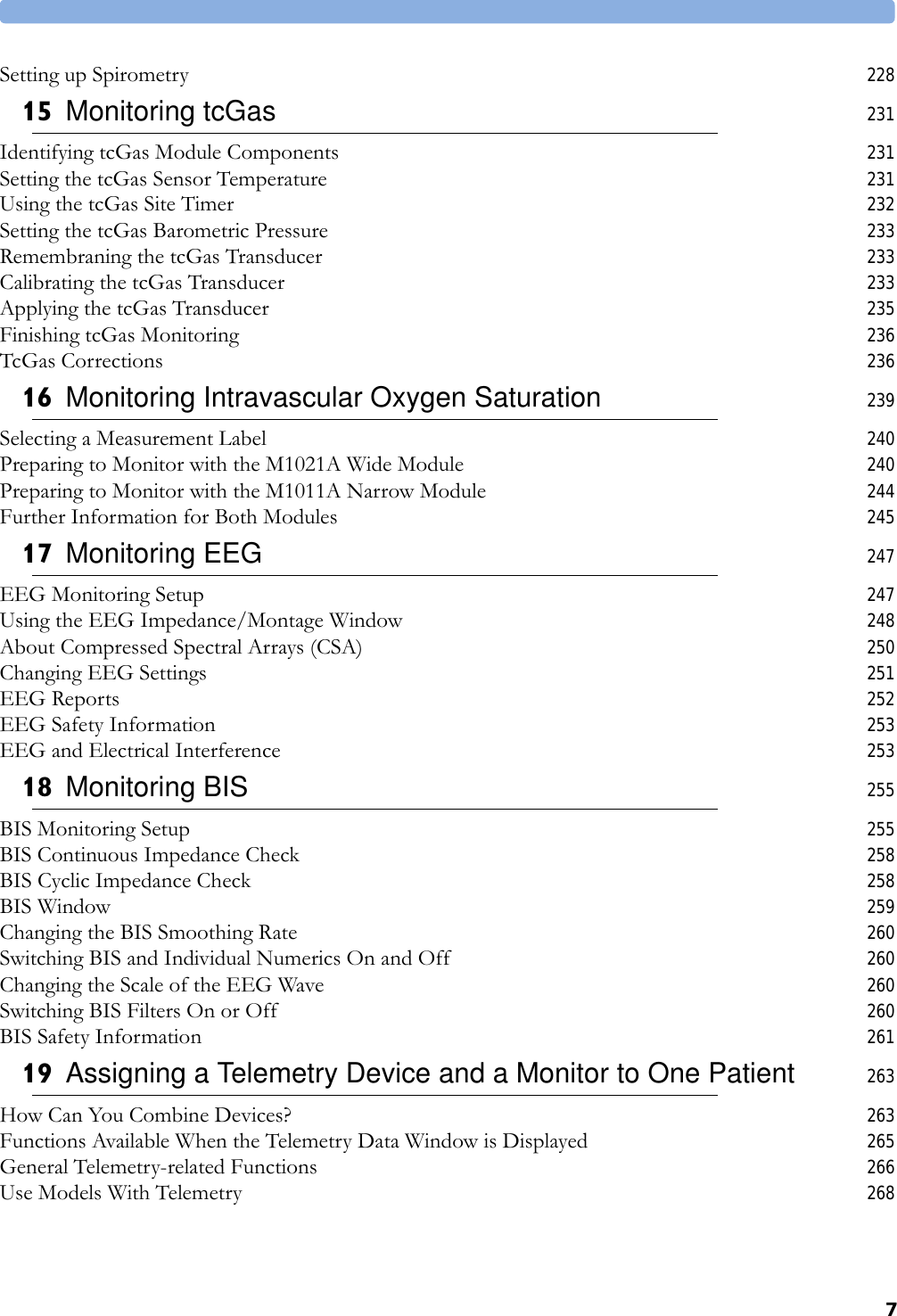
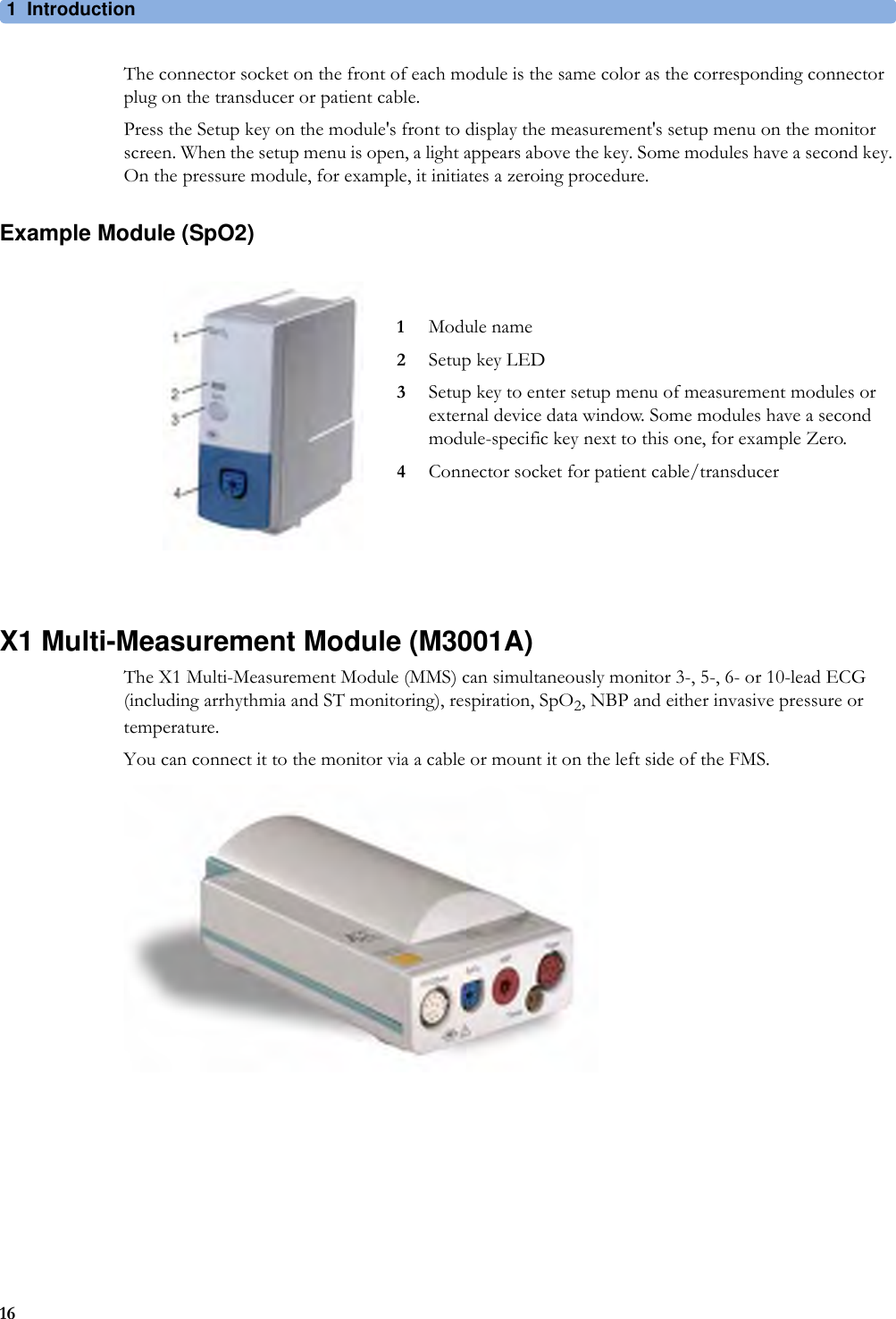
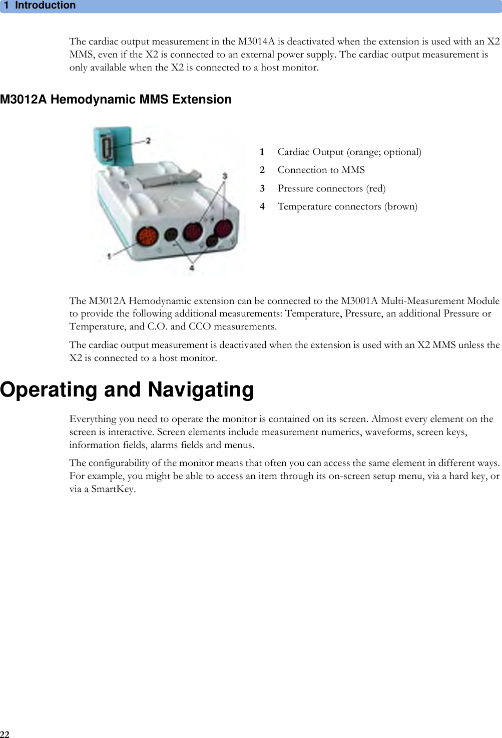
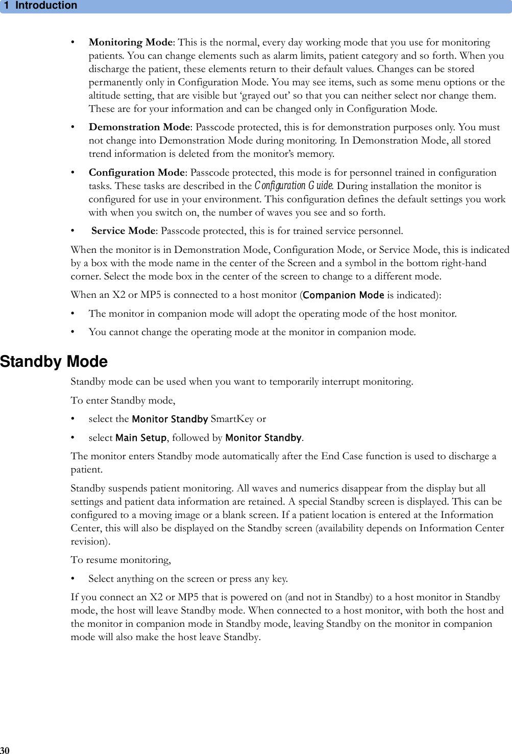
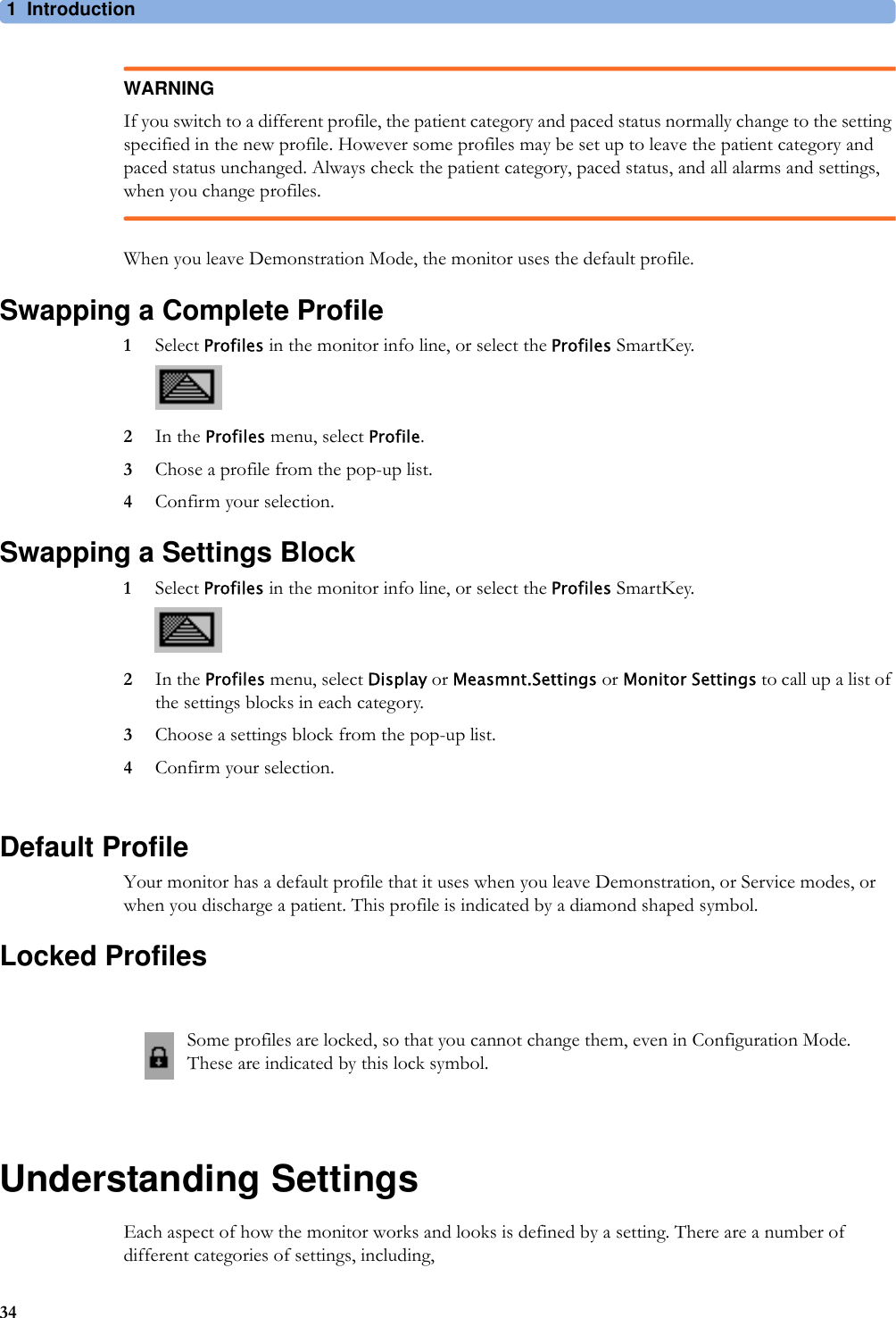
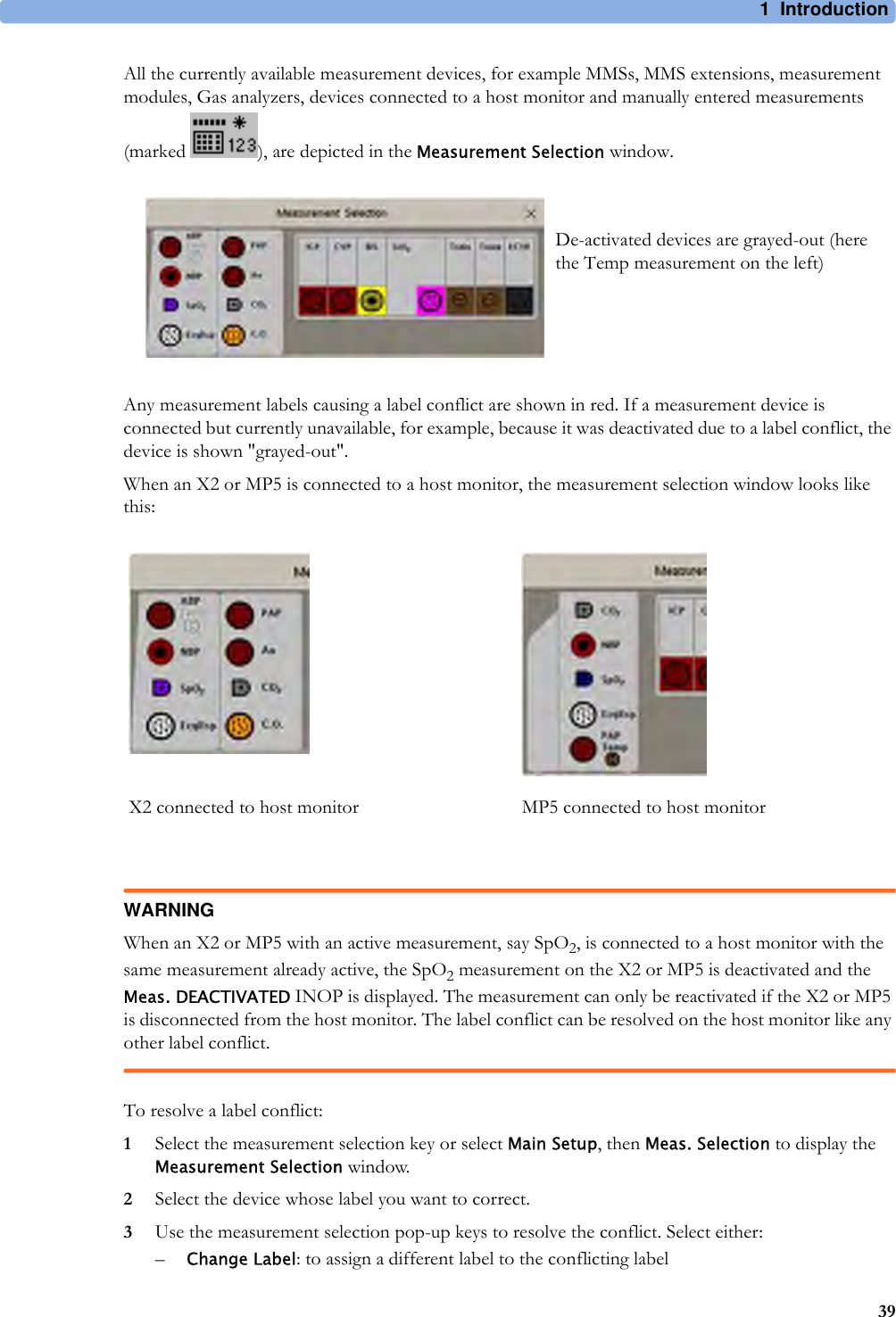
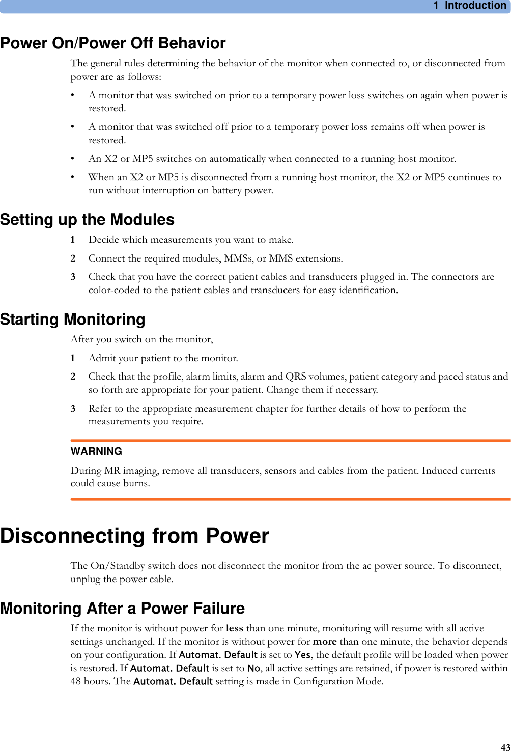
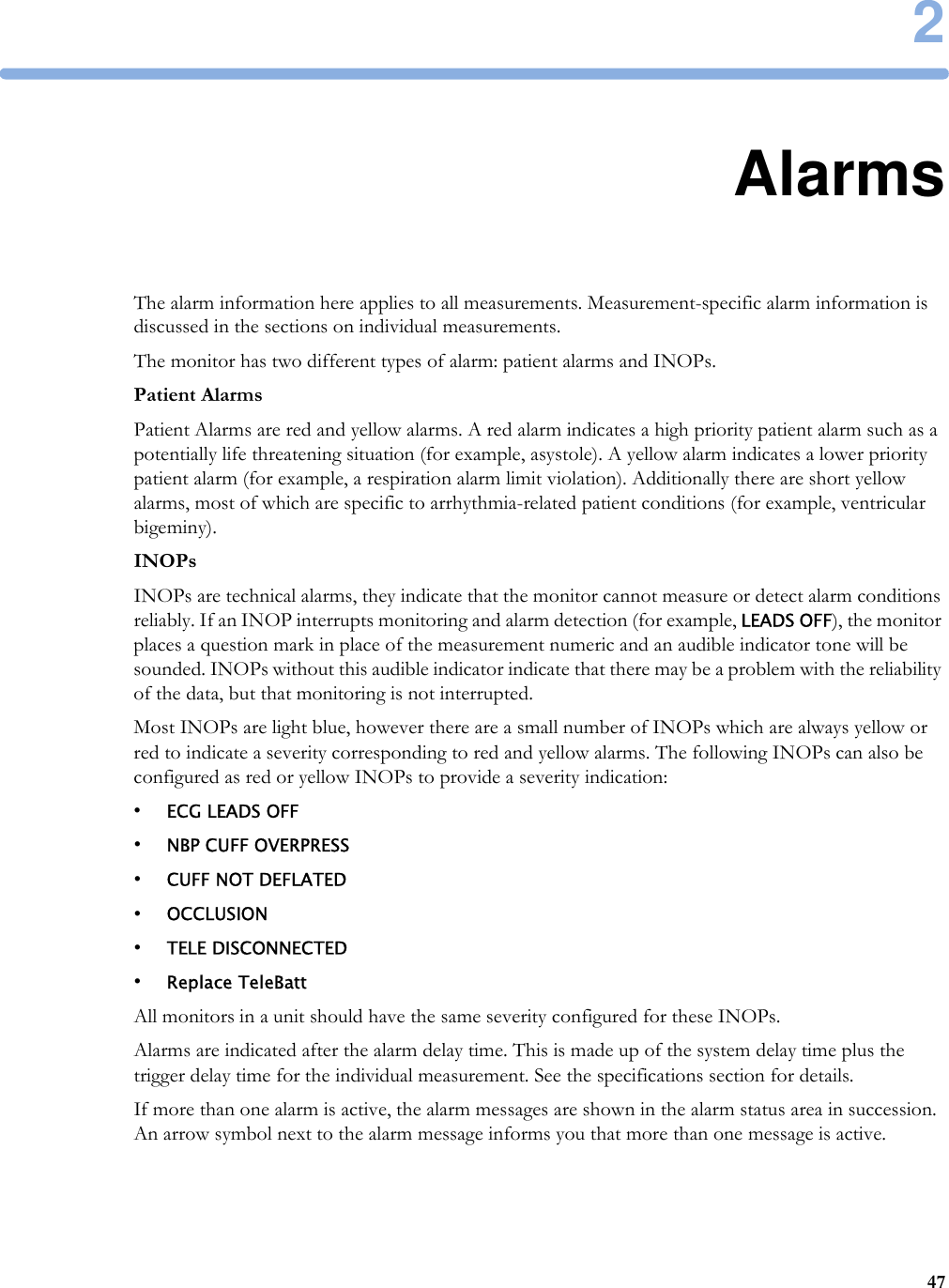
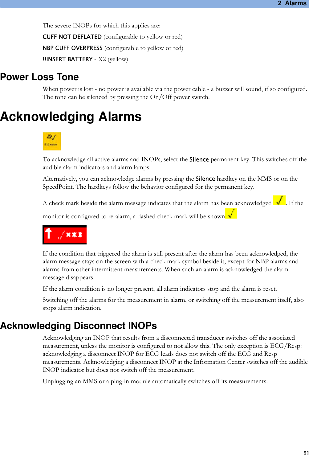
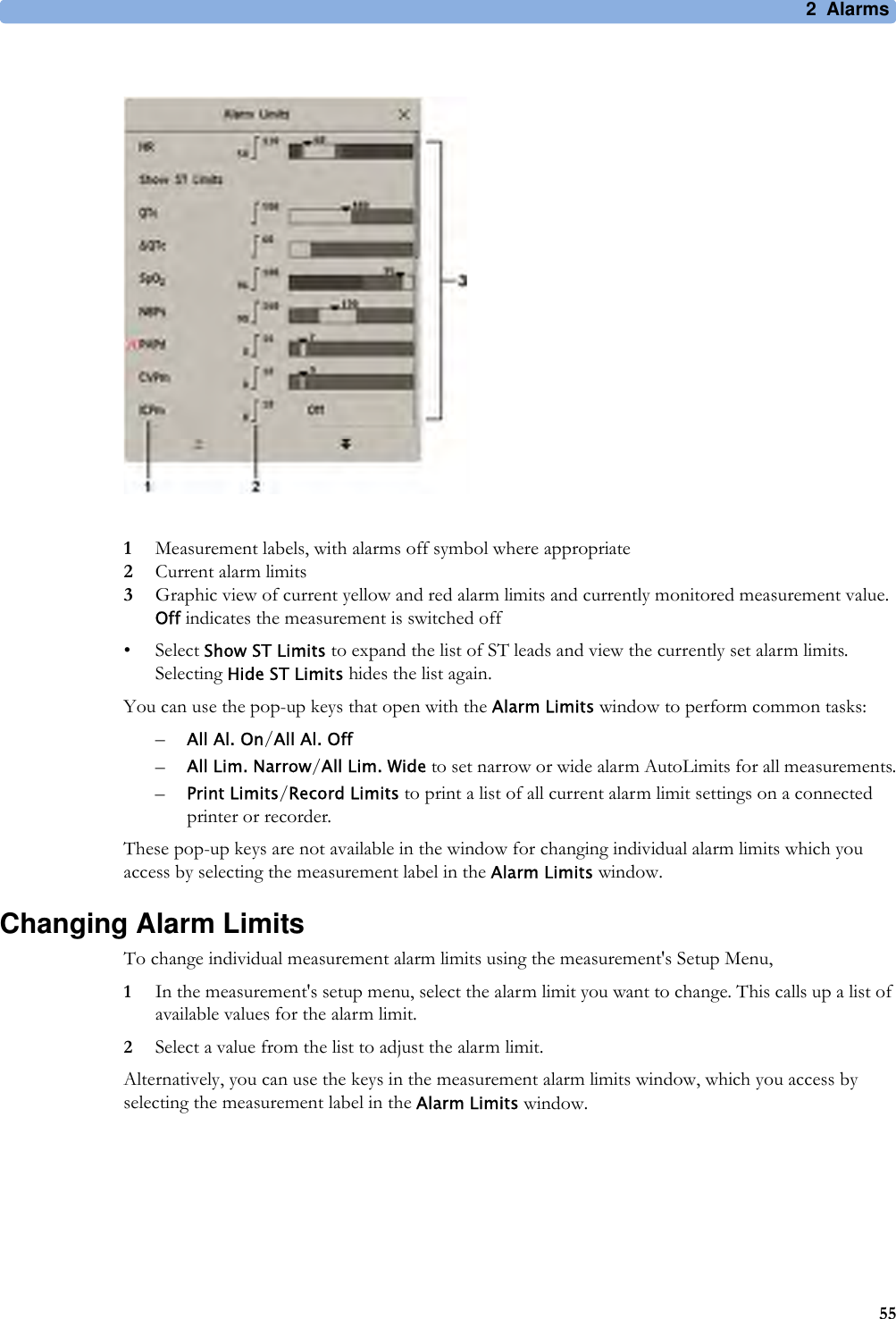
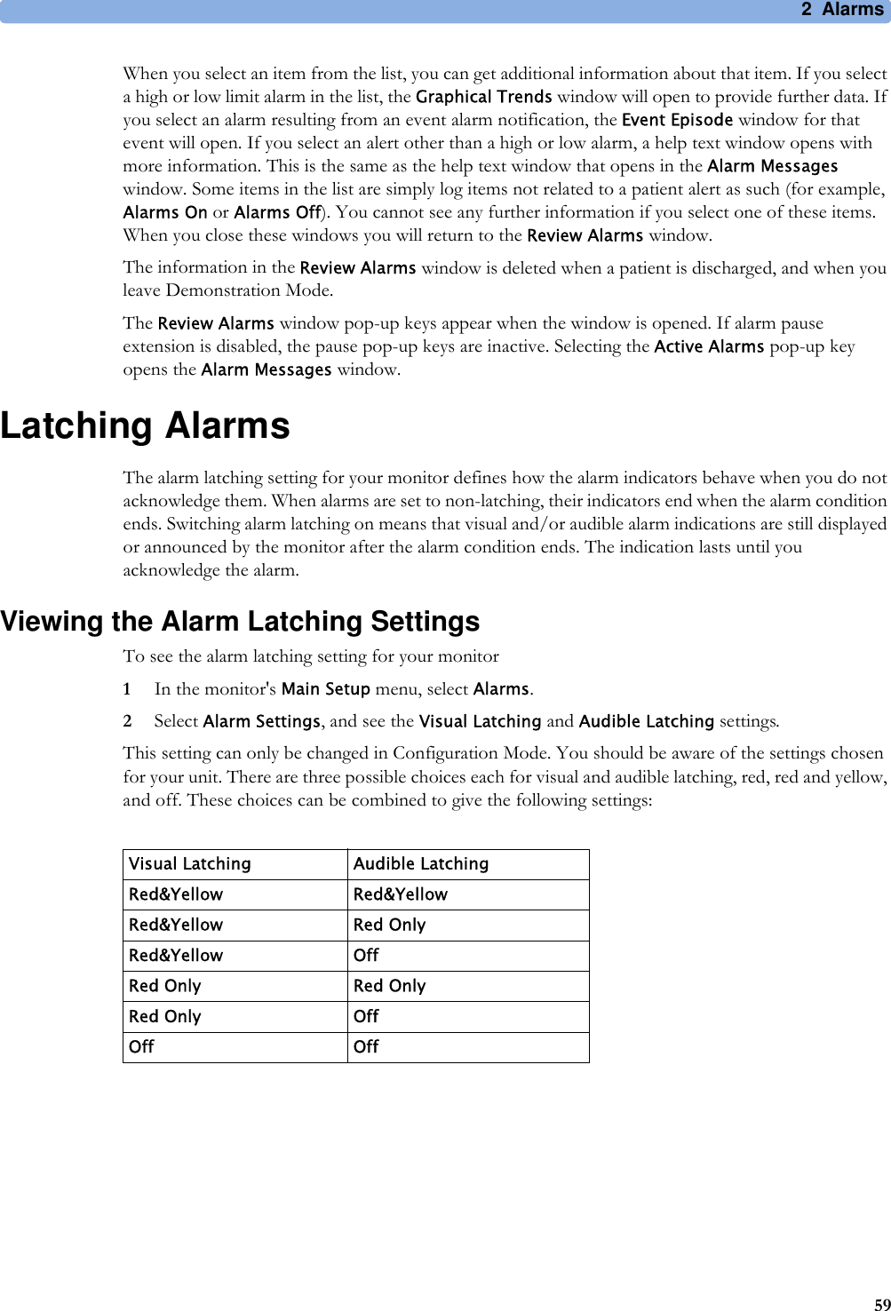
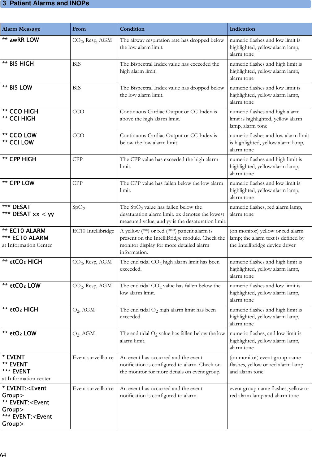
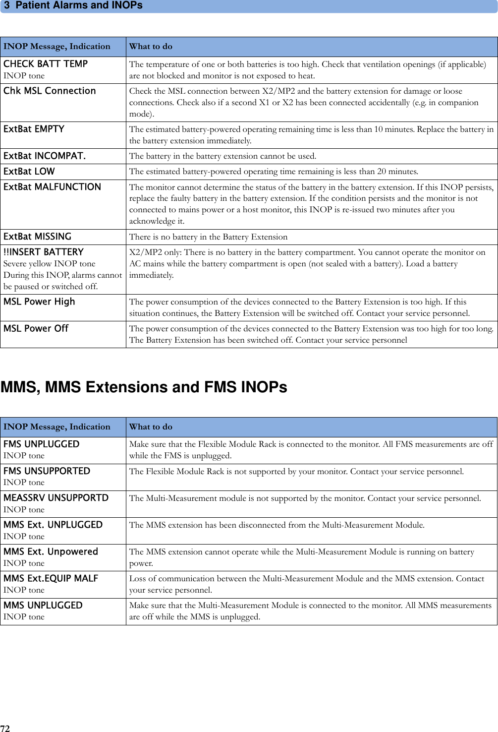
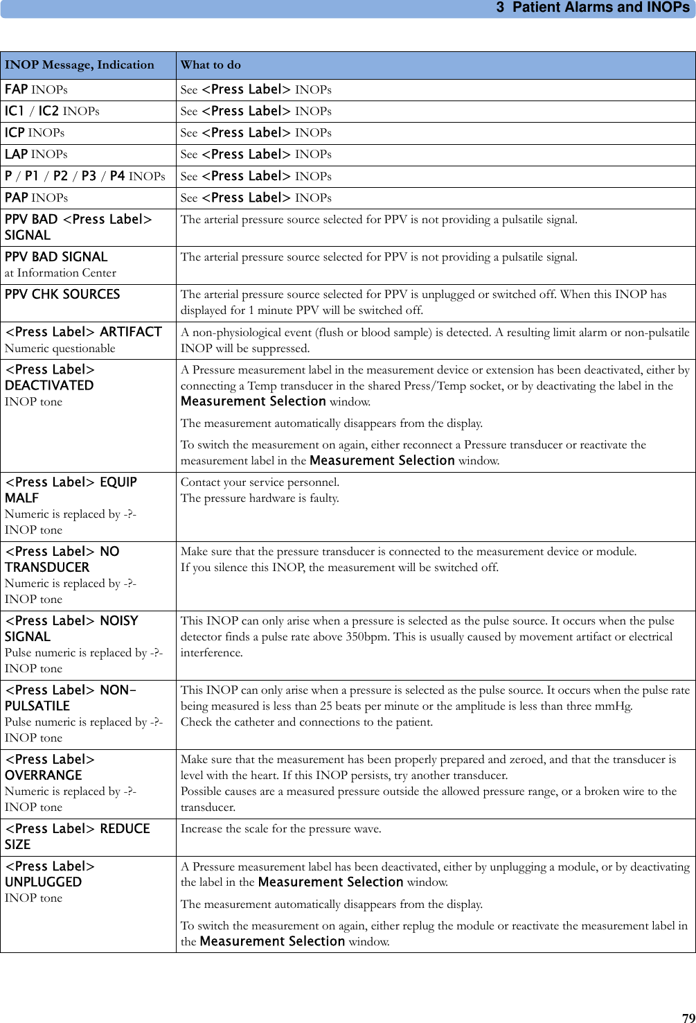
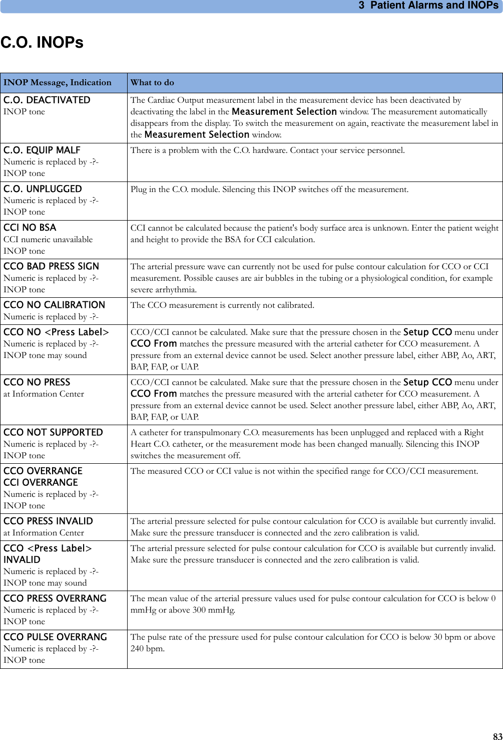
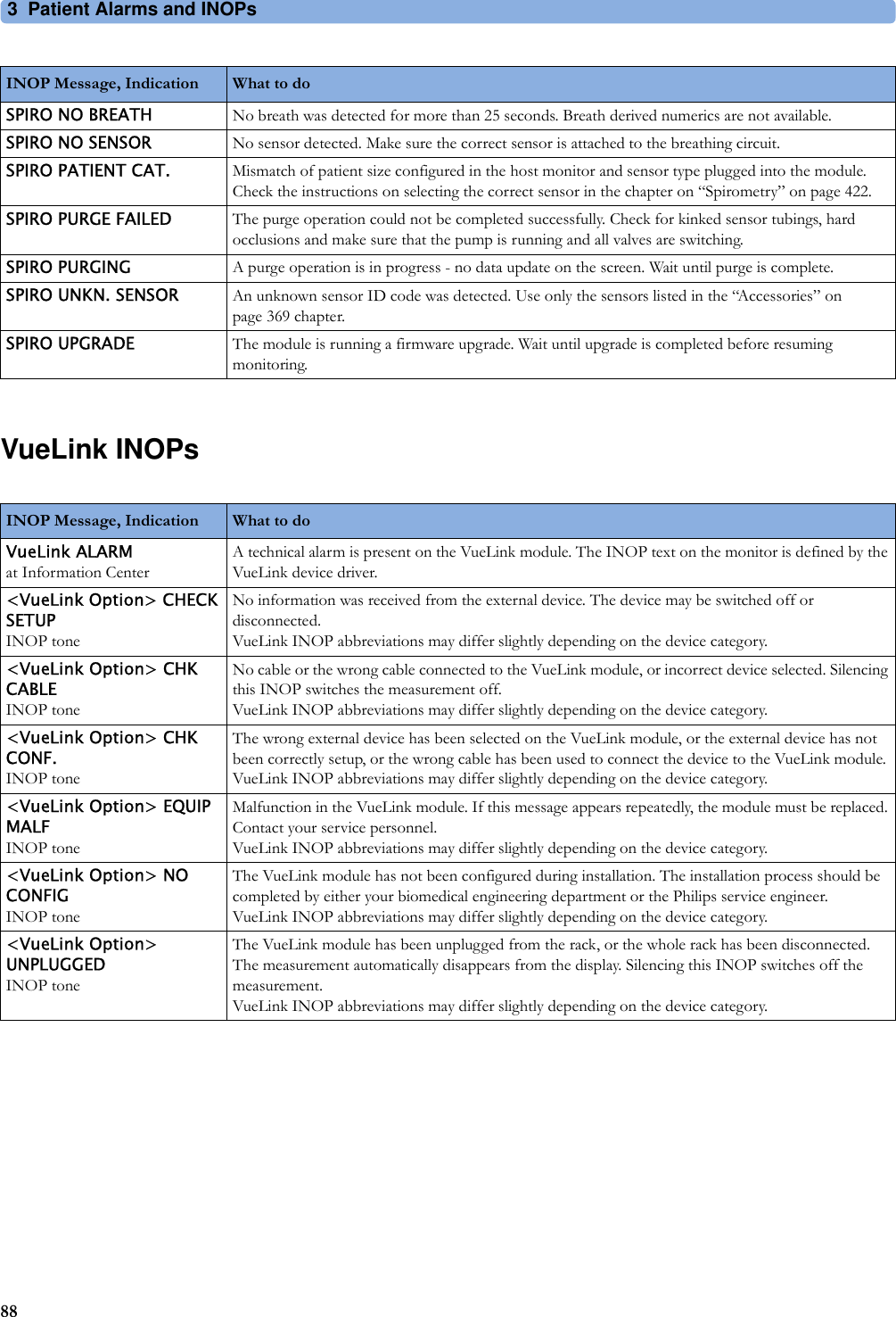
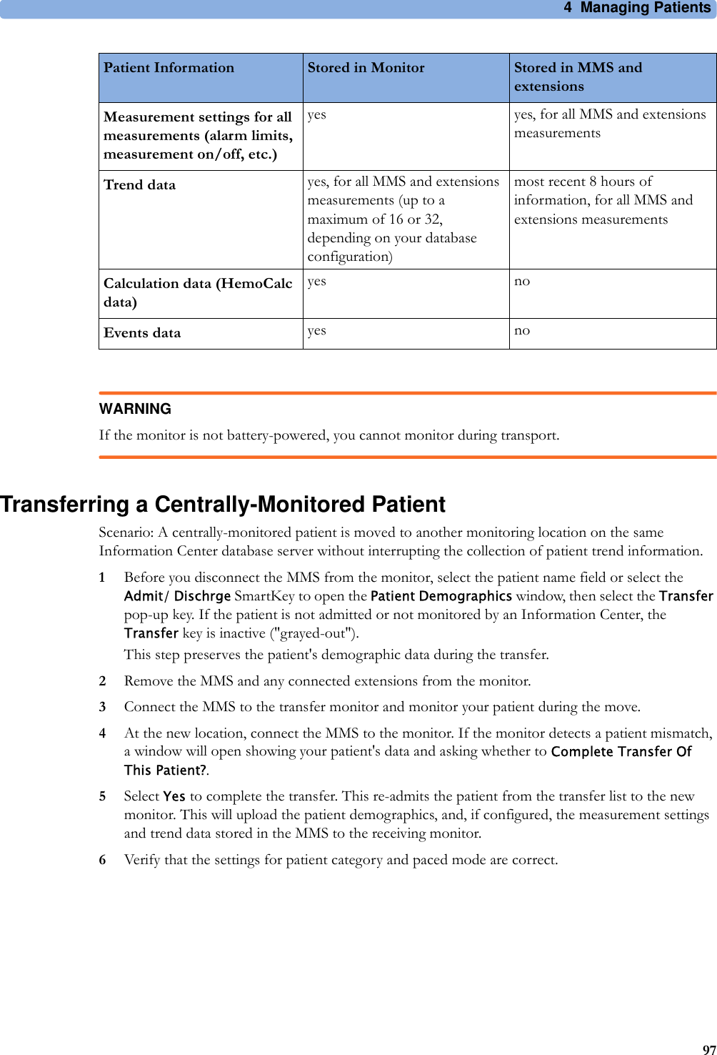
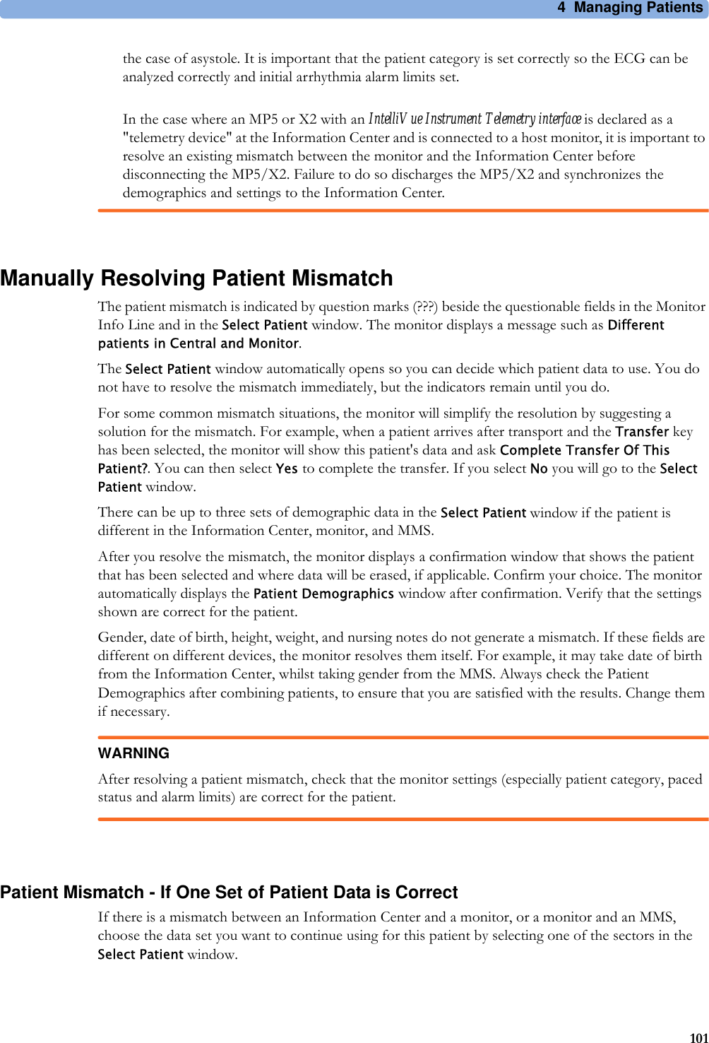
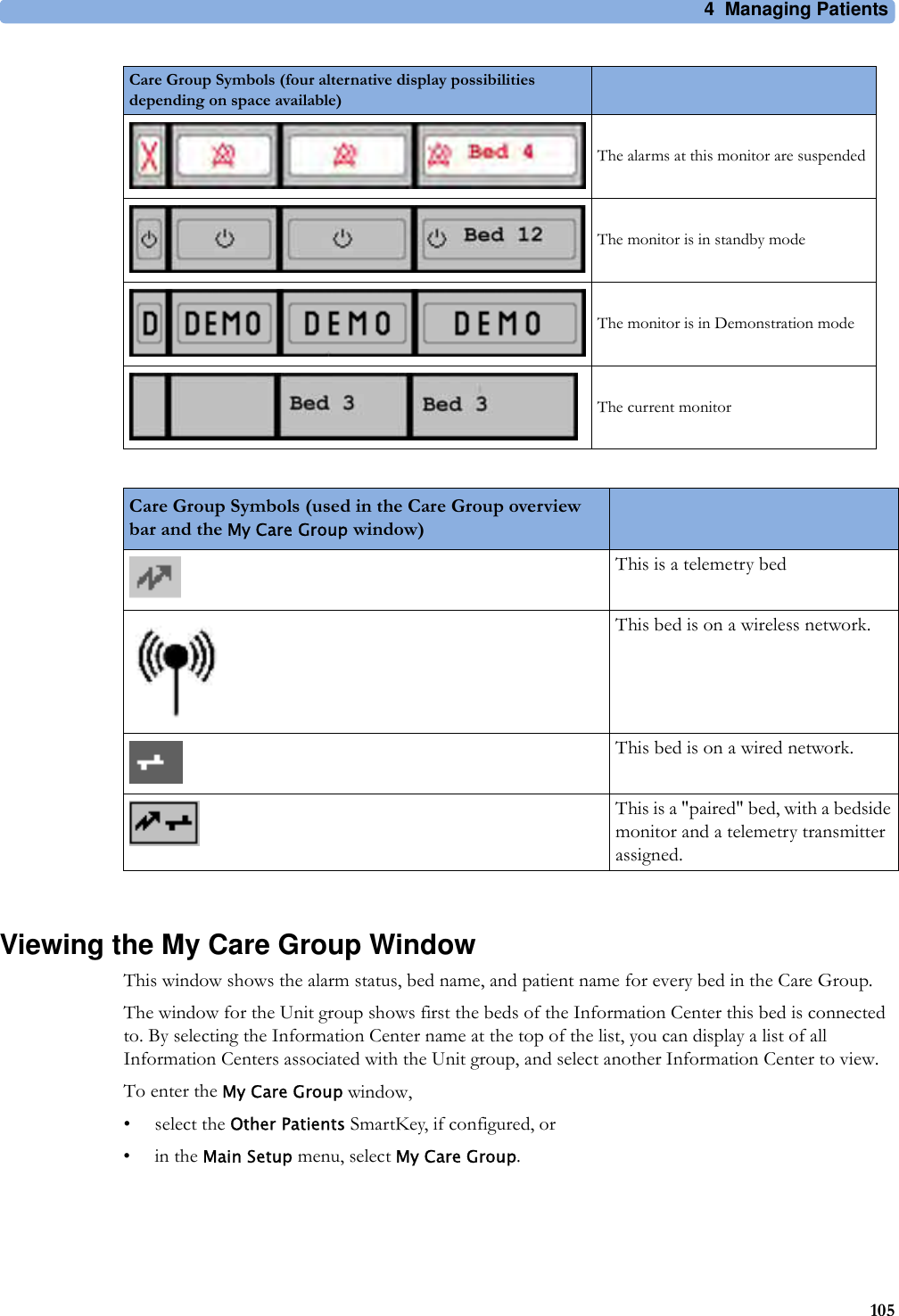
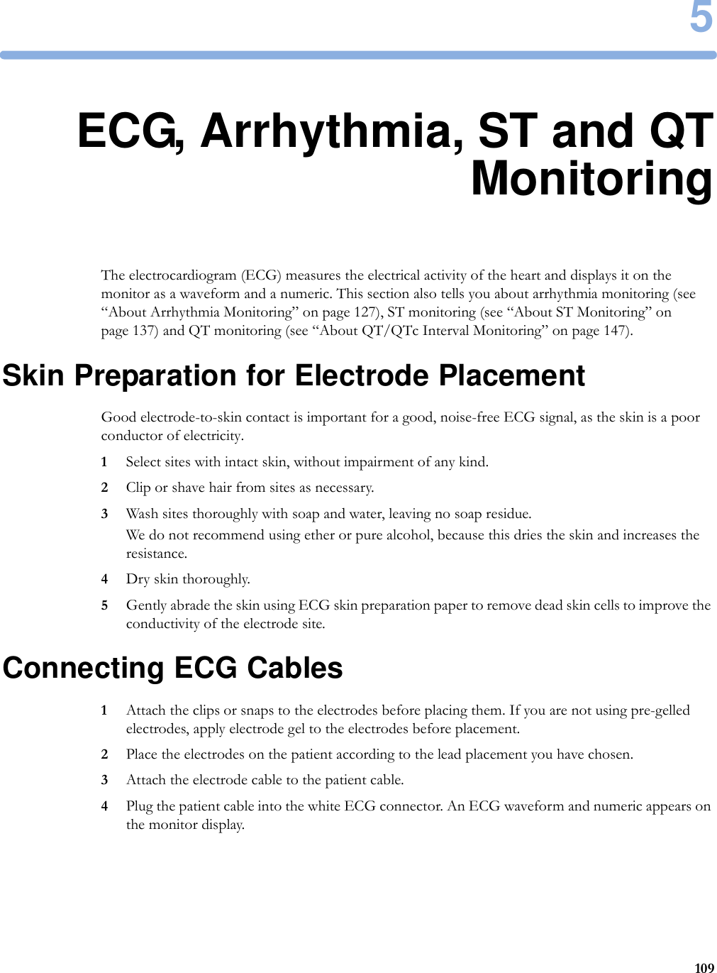
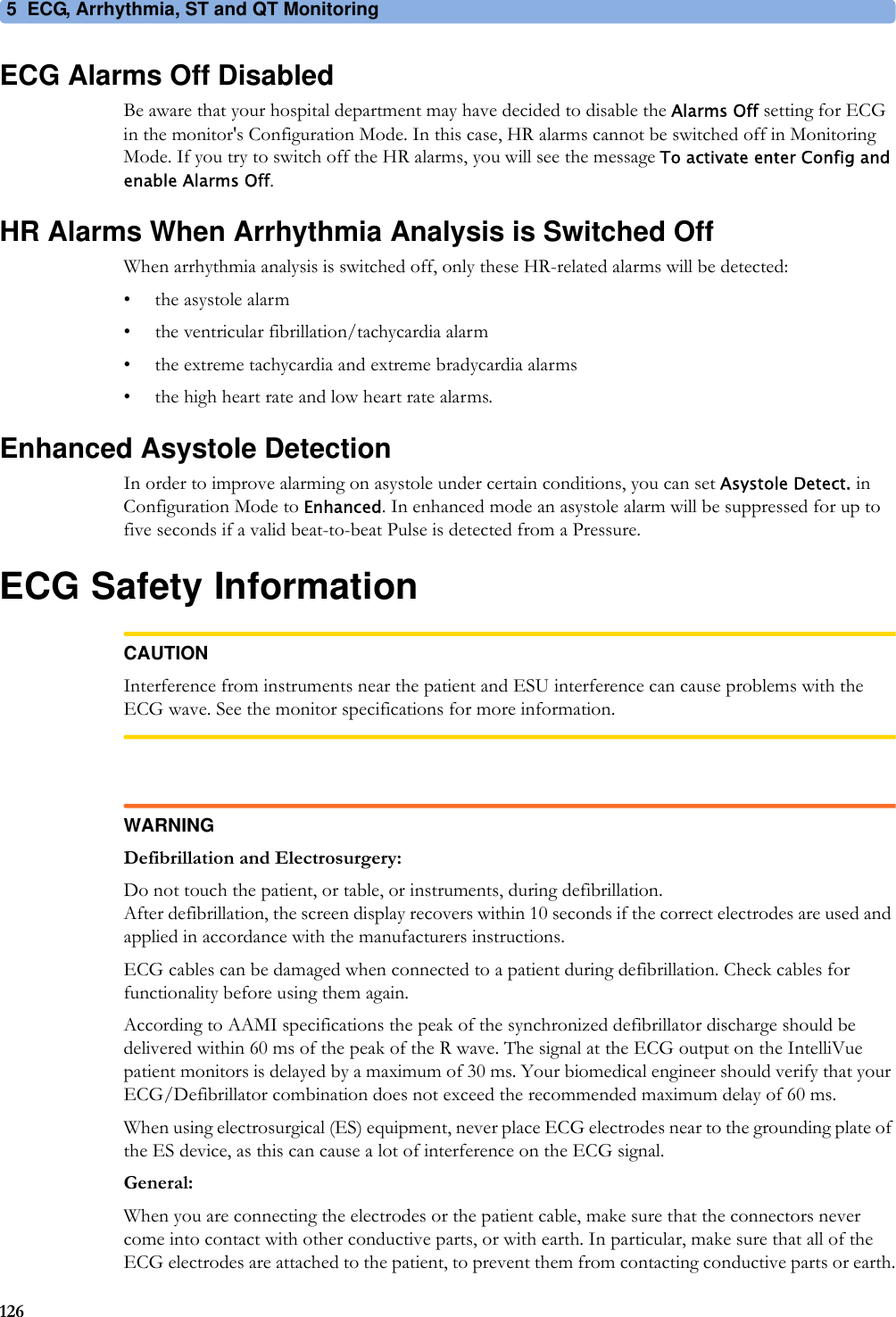
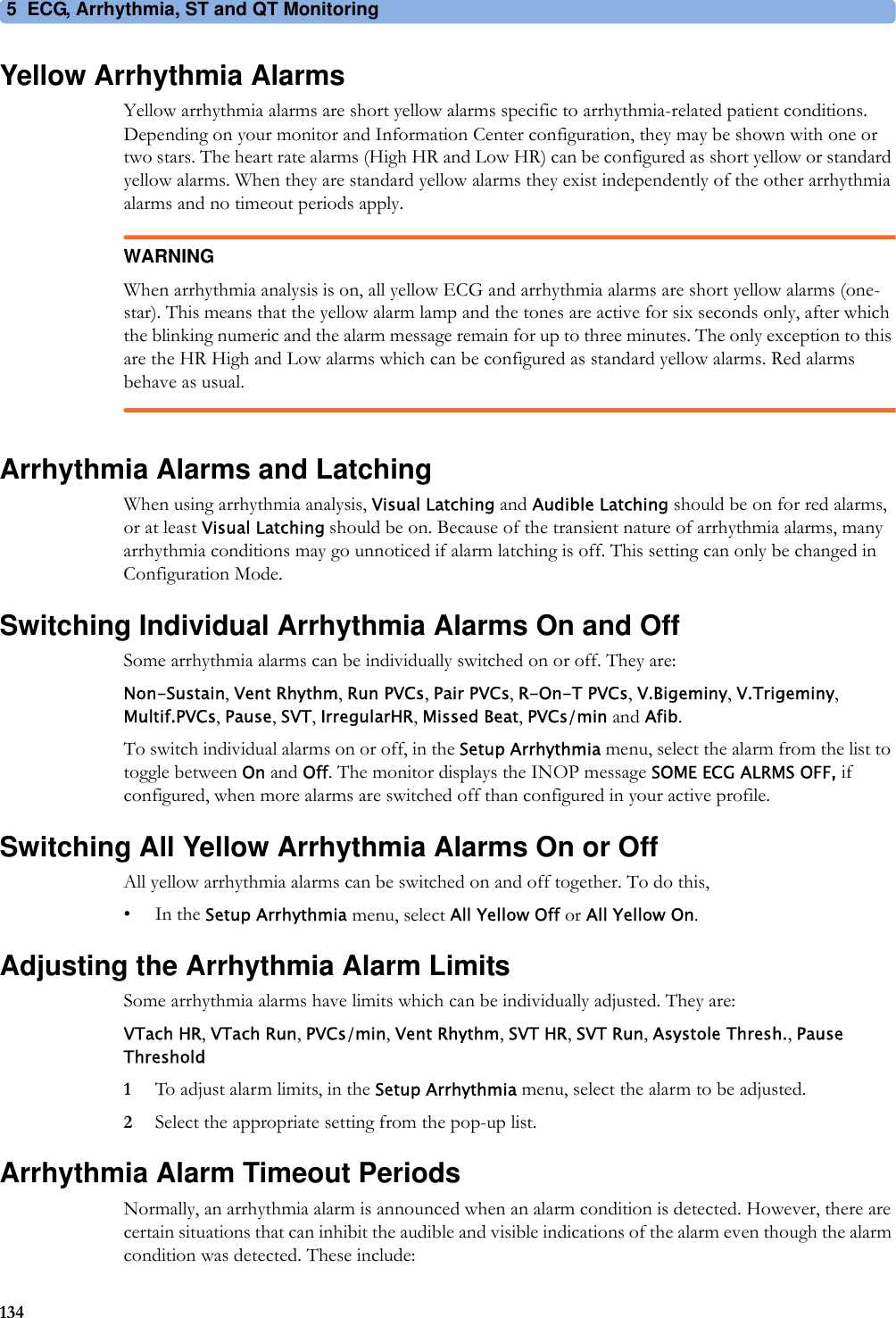
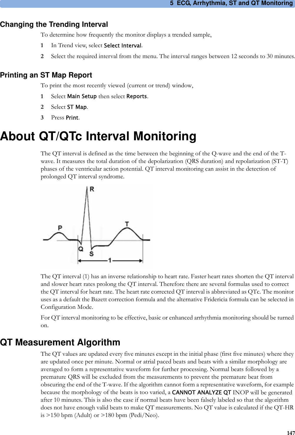
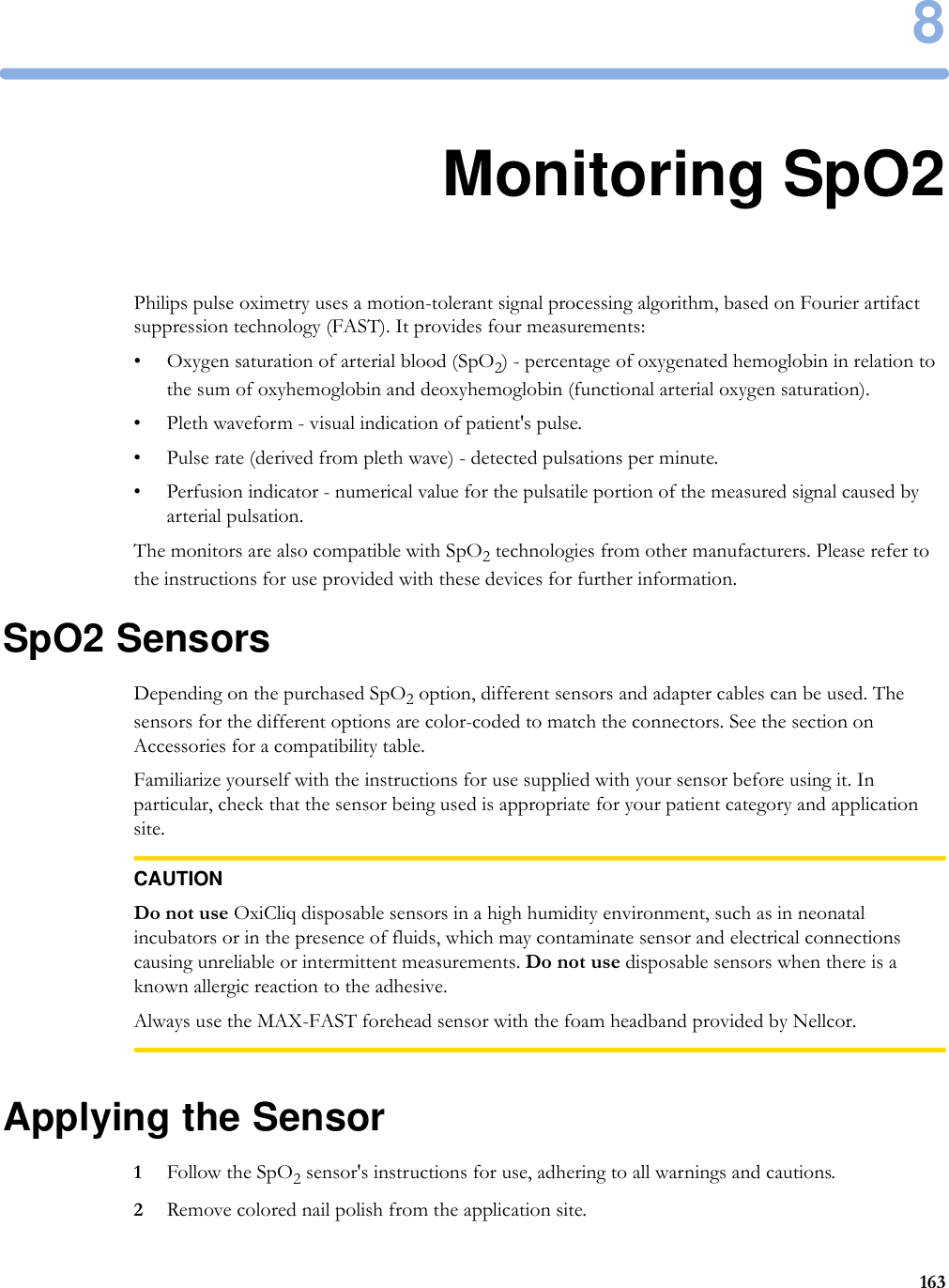
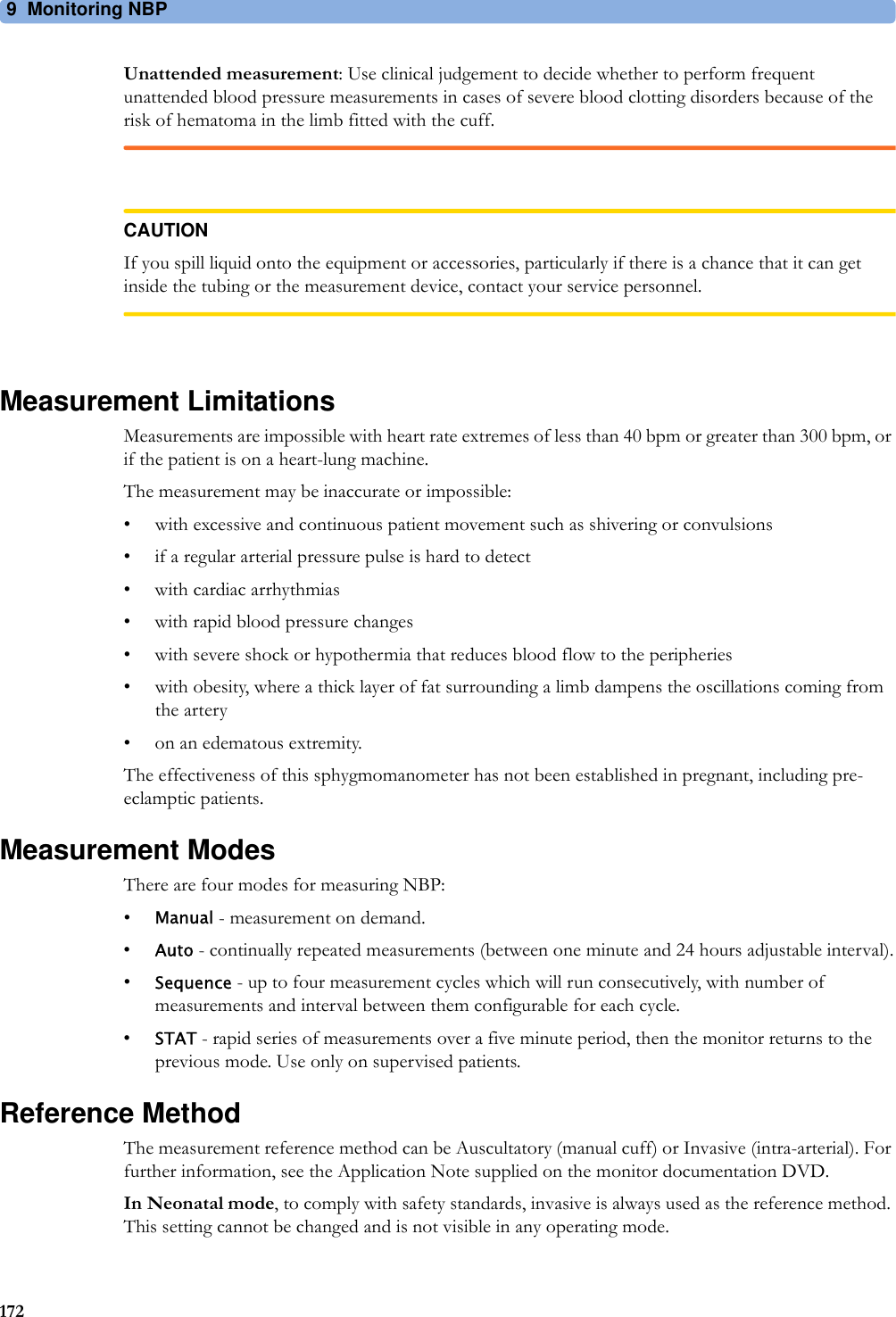
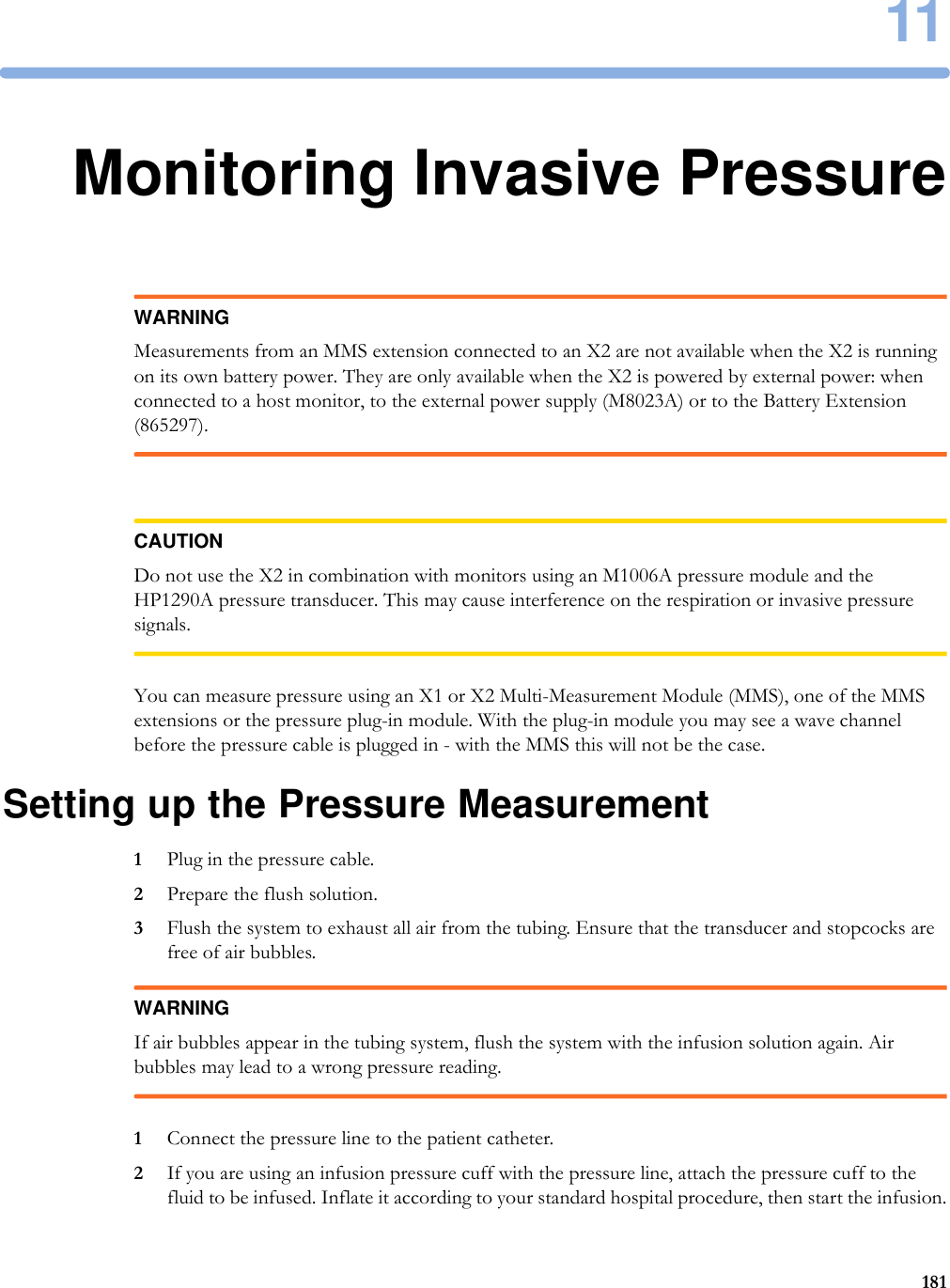
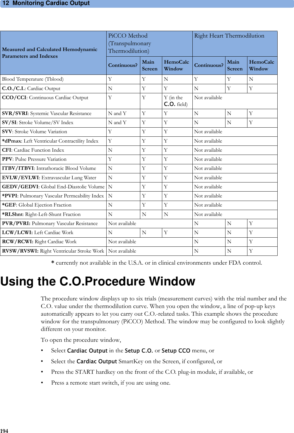
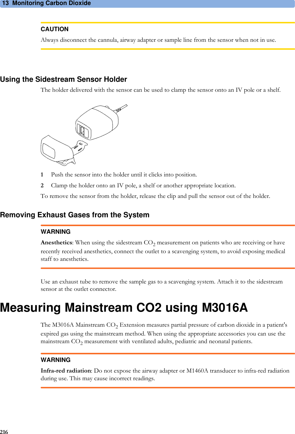
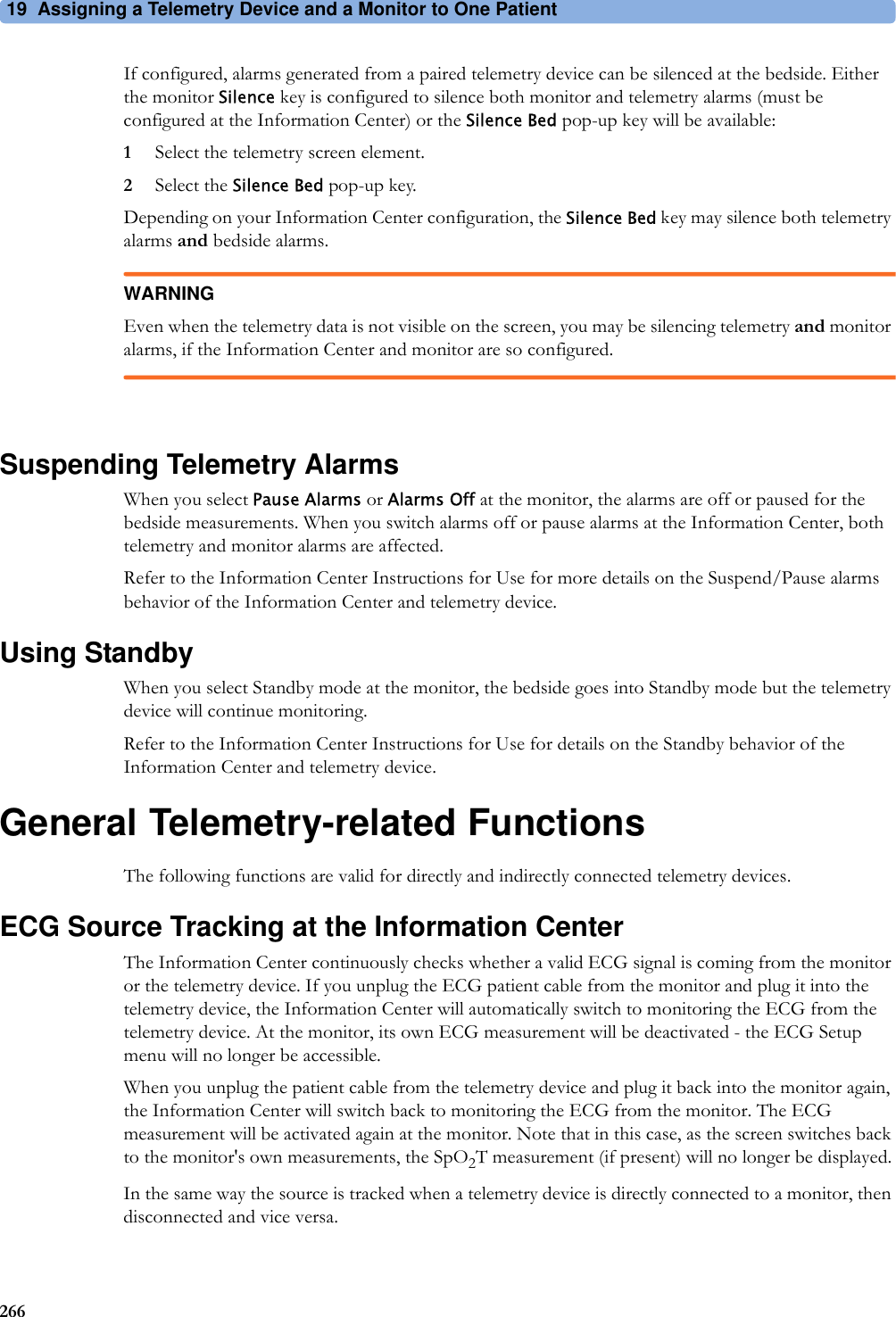
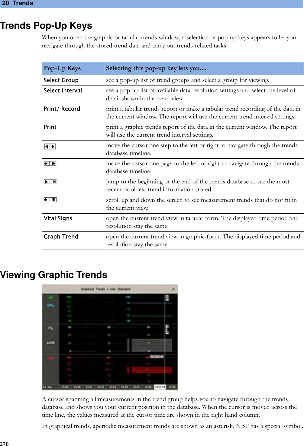
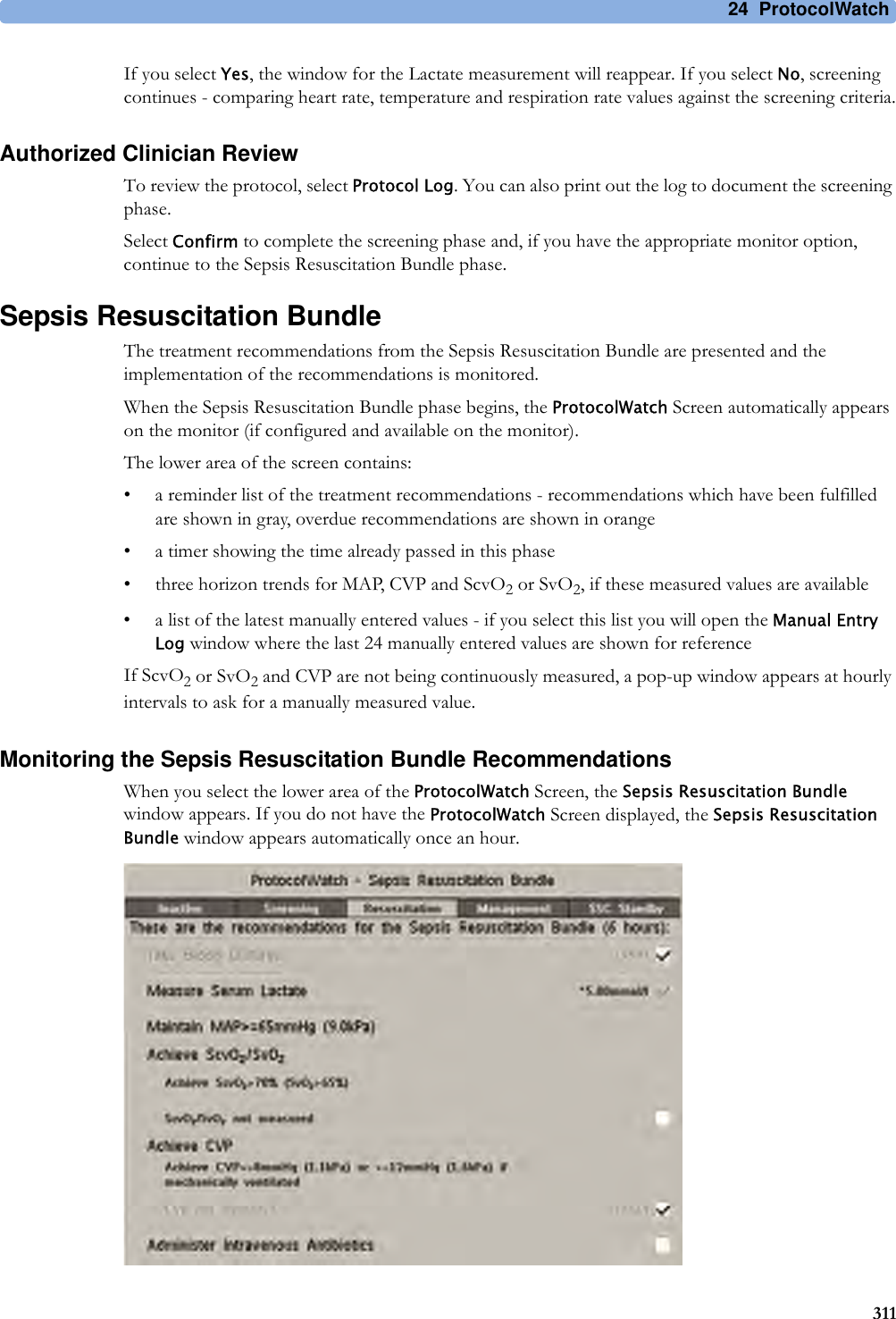
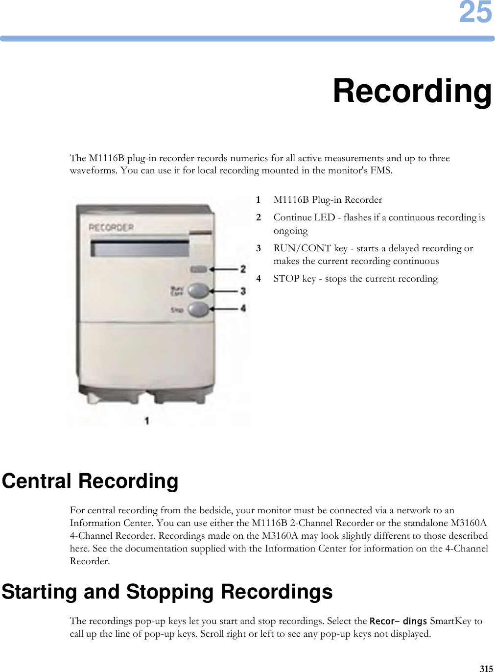
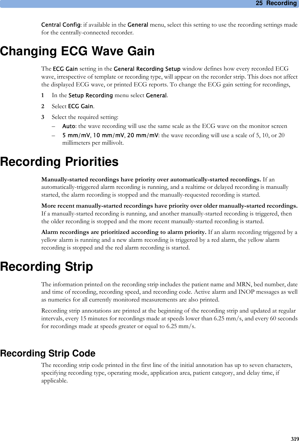
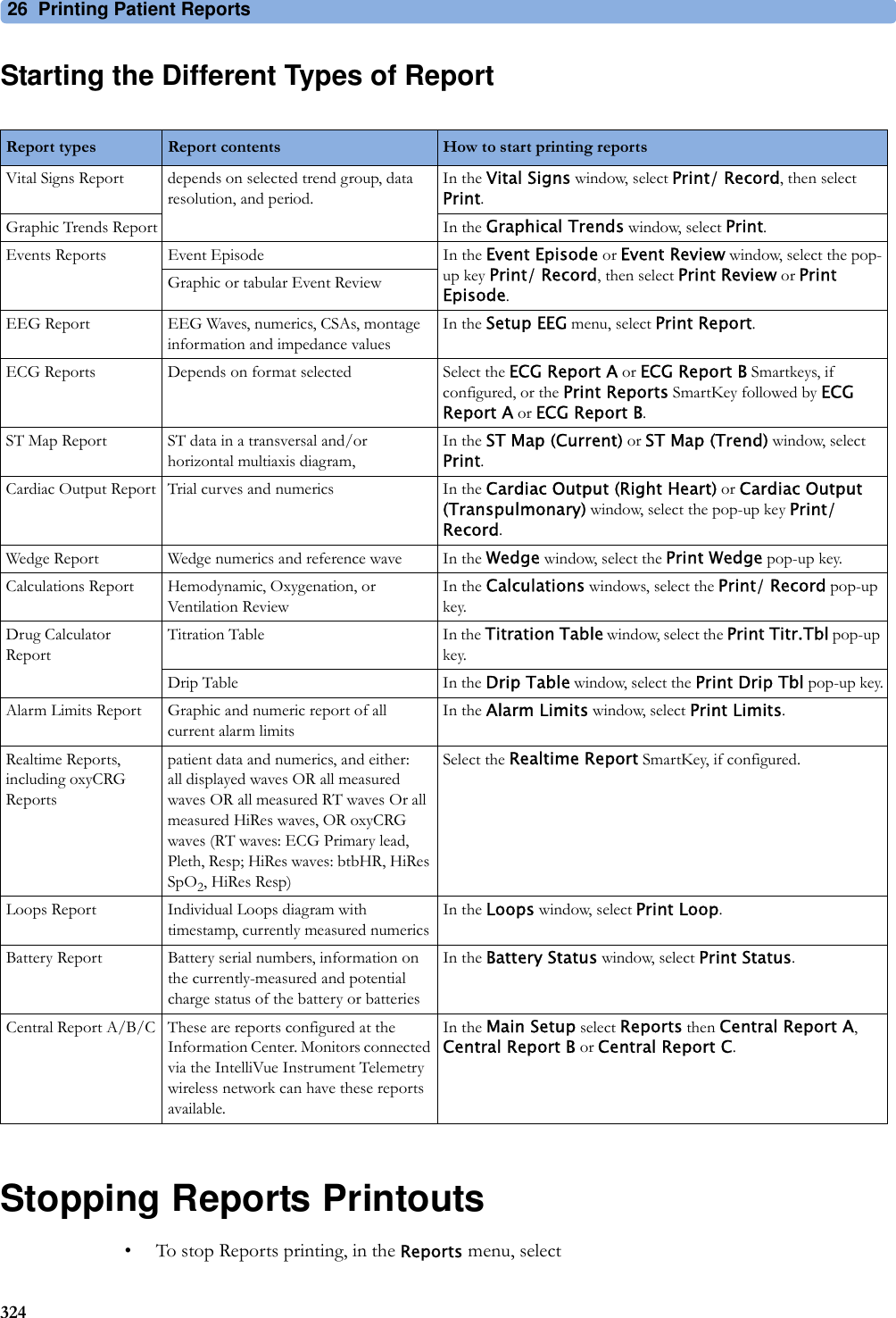
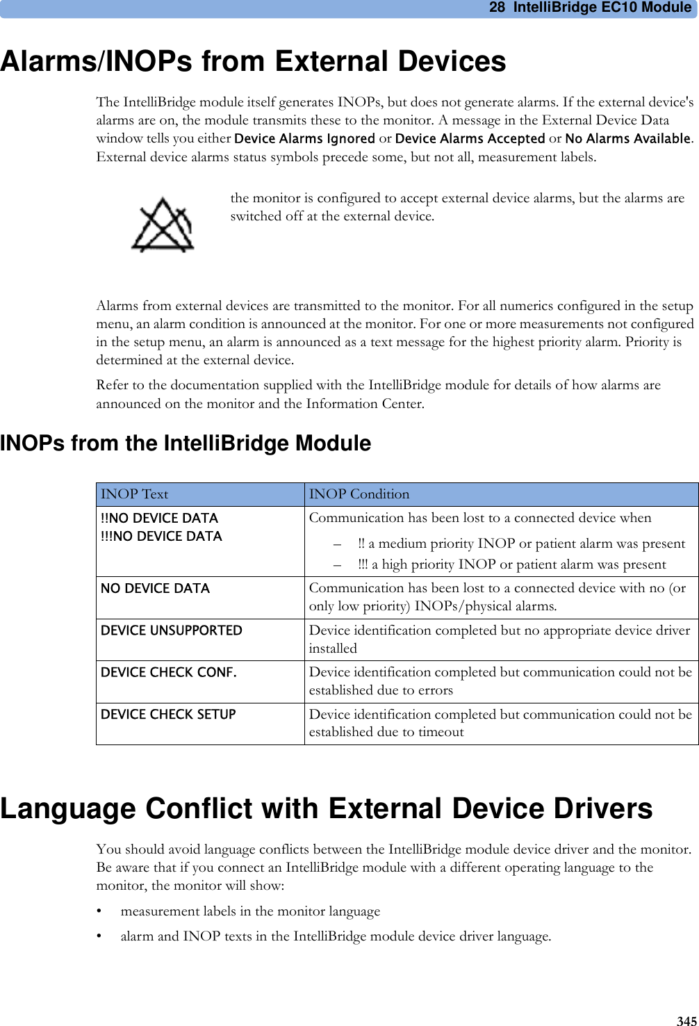
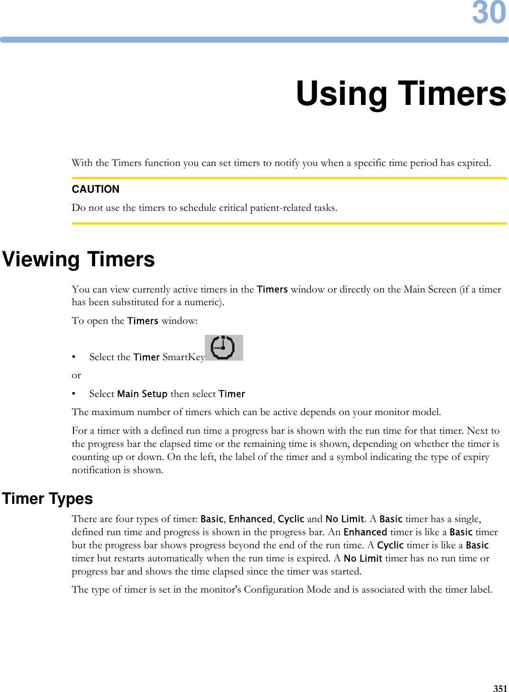
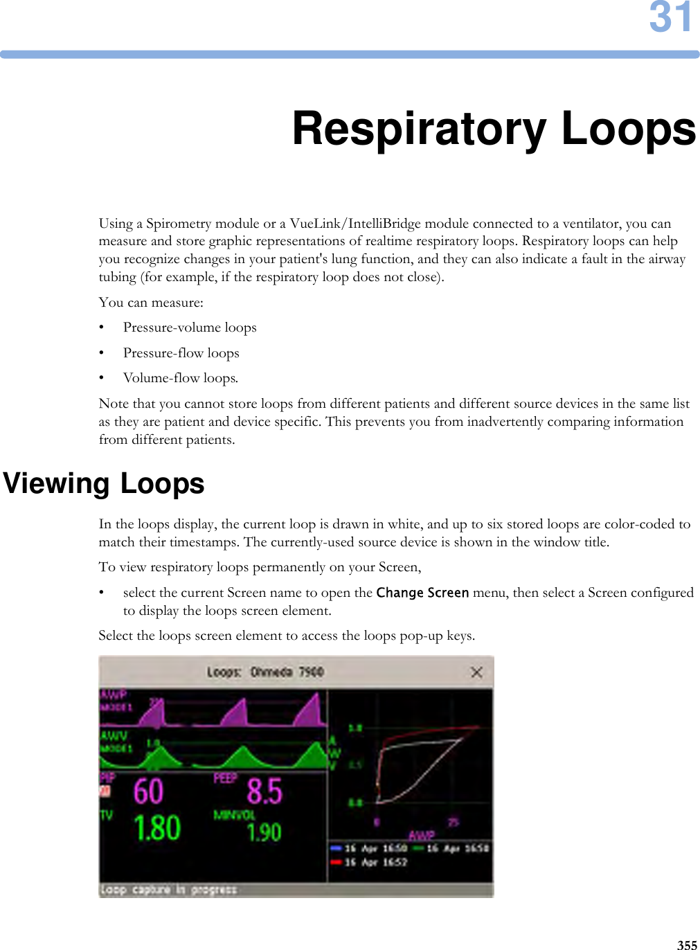
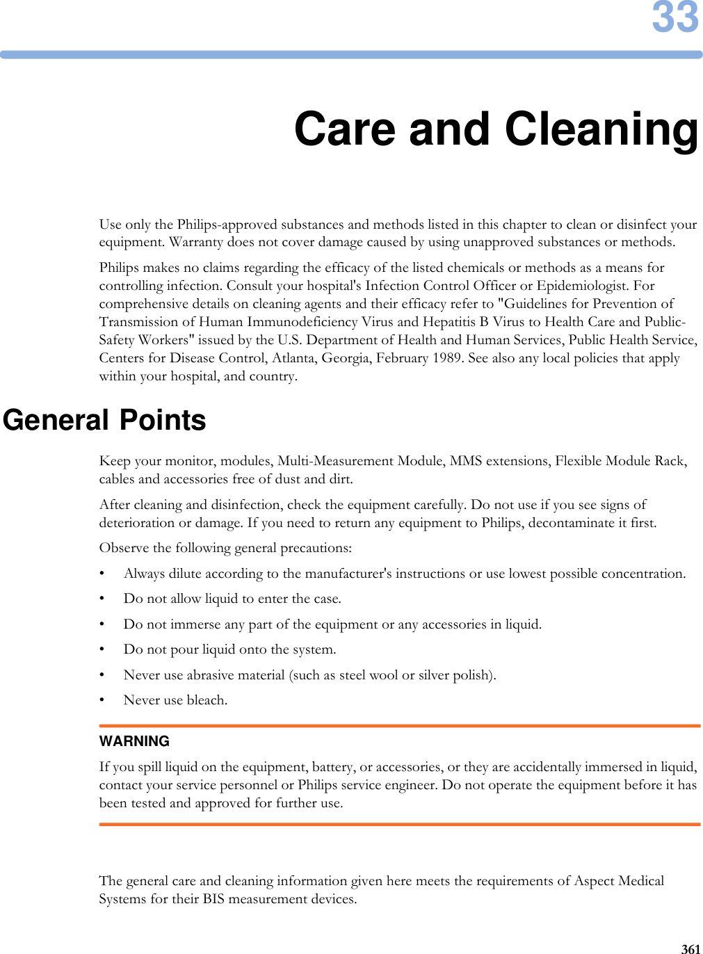
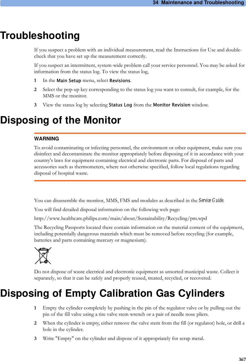
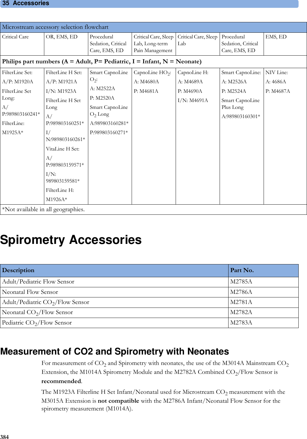
![3 Patient Alarms and INOPs75Pulse INOPsResp INOPsNBP INOPsINOP Message, Indication What to do PULSE NO ALARMINGNumeric is replaced by -?-INOP tonePulse has no alarming because the system pulse is measured by an external device. Select another pulse source to enable pulse alarming.INOP Message, Indication What to do Resp EQUIP MALFNumeric is replaced by -?-INOP toneContact your service personnel. The RESP hardware is faulty.Resp ERRATICNumeric is replaced by -?-The monitor has detected too many artifacts in the measured Resp signal. Check that the RA and LL electrodes are correctly attached and have not dried out.Resp LEADS OFFNumeric is replaced by -?-INOP toneNot all the required leads for Resp monitoring are attached. Make sure that the RA and LL leads are attached.INOP Message, Indication What to do !! CUFF NOT DEFLAT!!!CUFF NOT DEFLATNumeric is displayed with a -?-Severe yellow/red INOP toneDuring this INOP, alarms cannot be paused or switched off.Remove the cuff from the patient. Make sure that the tubing is not kinked or twisted and that the correct patient category is selected. Try repeating the measurement. You can silence the INOP, but the INOP message remains visible until the next NBP measurement is started or the Stop All SmartKey is selected.[Adult or pediatric patients: The NBP cuff pressure has exceeded 15 mmHg (2kPa) for more than 3 minutes. Neonatal patients: The NBP cuff pressure has exceeded 5mmHg (0.7kPa) for more than 90 seconds.]!! CUFF OVERPRESS!!!CUFF OVERPRESSNumeric displayed with -?-Severe yellow/red INOP toneDuring this INOP, alarms cannot be paused or switched off.The NBP cuff pressure exceeds the overpressure safety limits. Remove the cuff from the patient. Make sure that the tubing is not kinked or twisted and that the correct patient category is selected. Try restarting the measurement. You can silence this INOP, but the INOP message remains visible until the next measurement is started or the Stop All SmartKey is selected.](https://usermanual.wiki/Philips-Medical-Systems-North-America/SRRBV2.User-Manual-Olympus/User-Guide-1340937-Page-75.png)
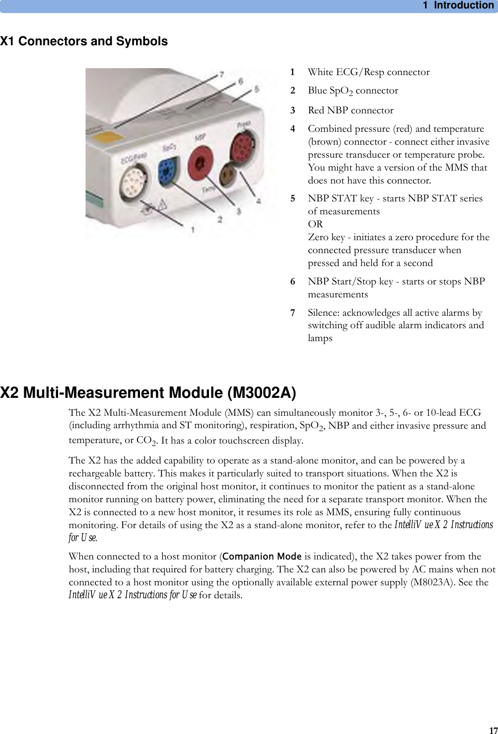
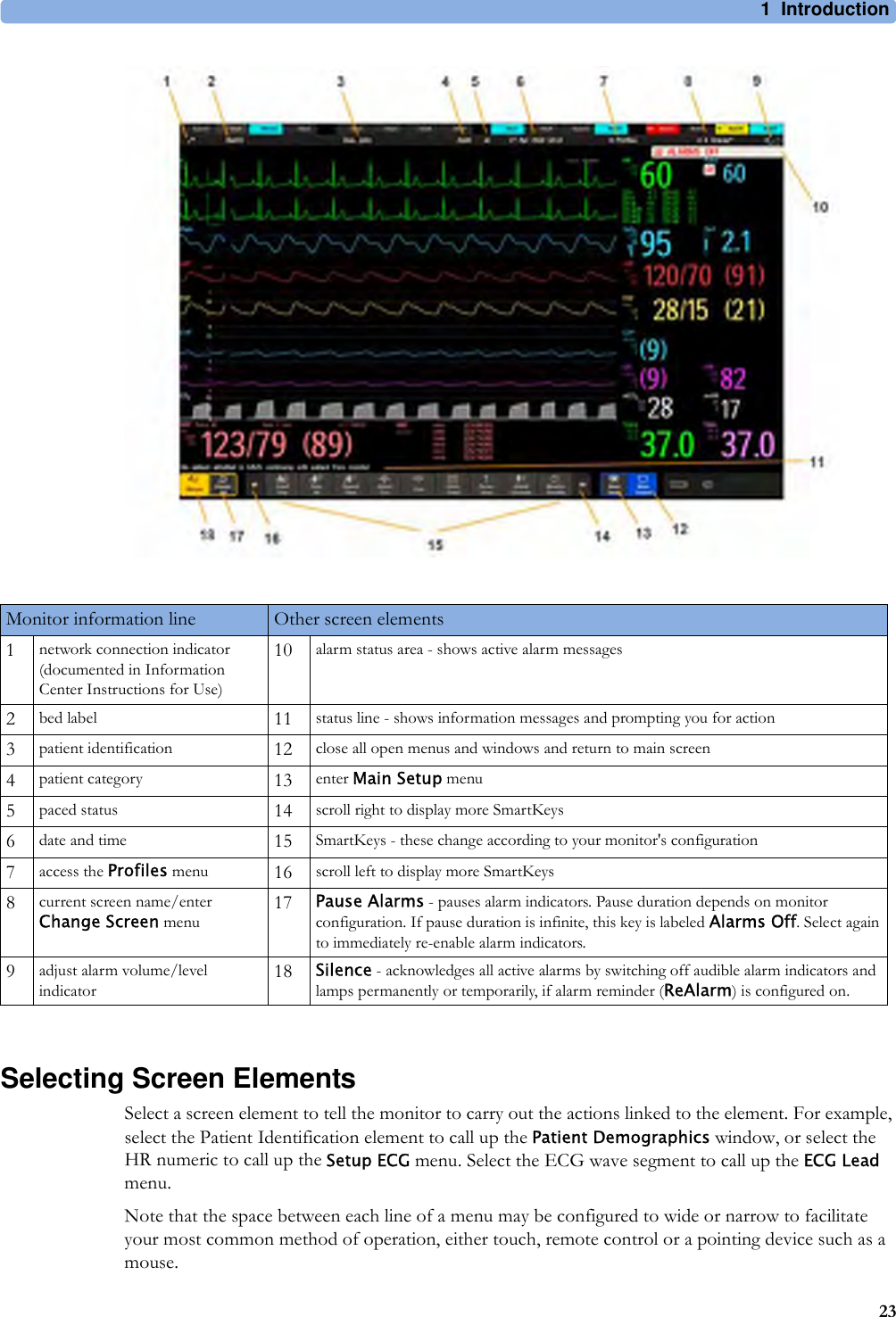
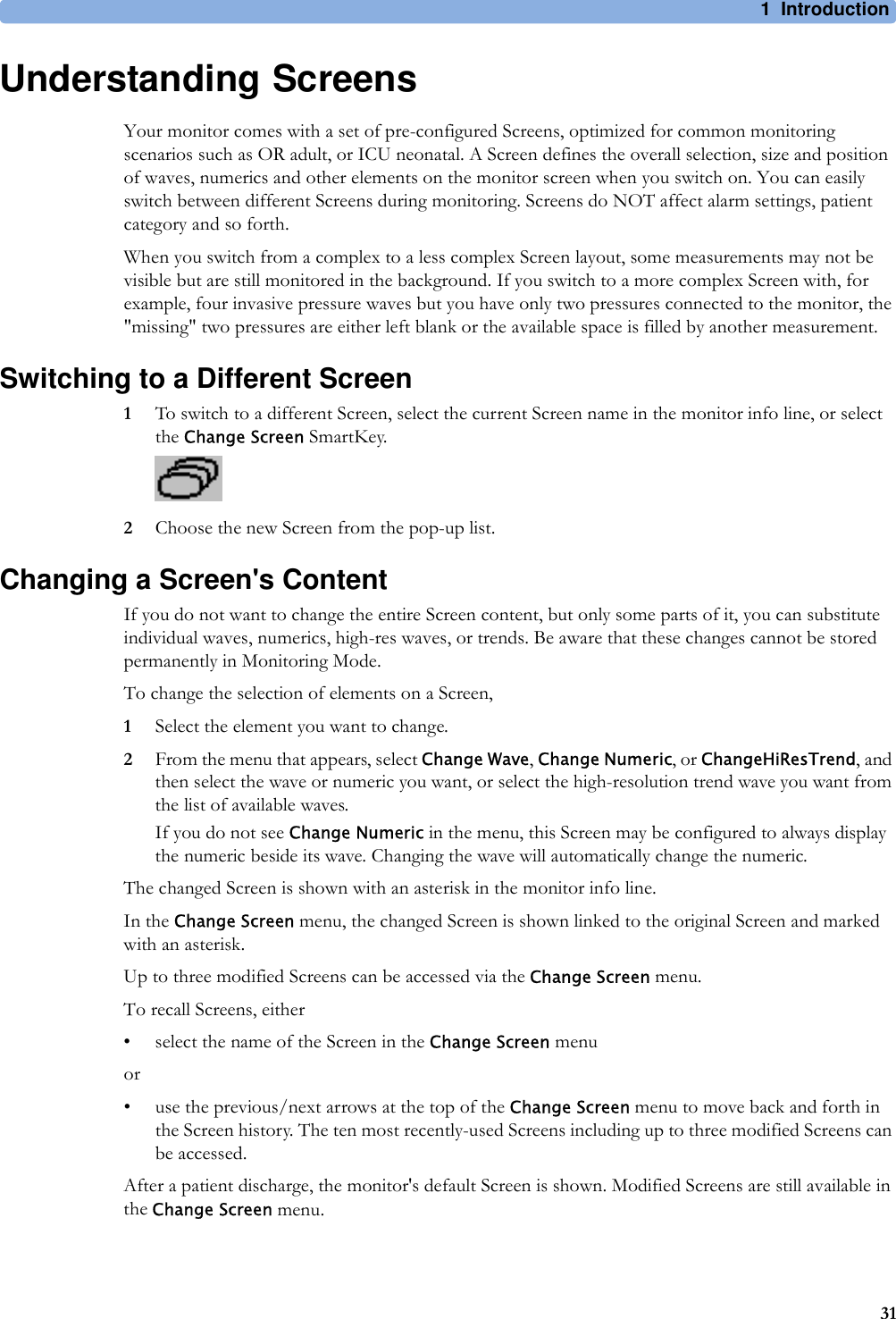
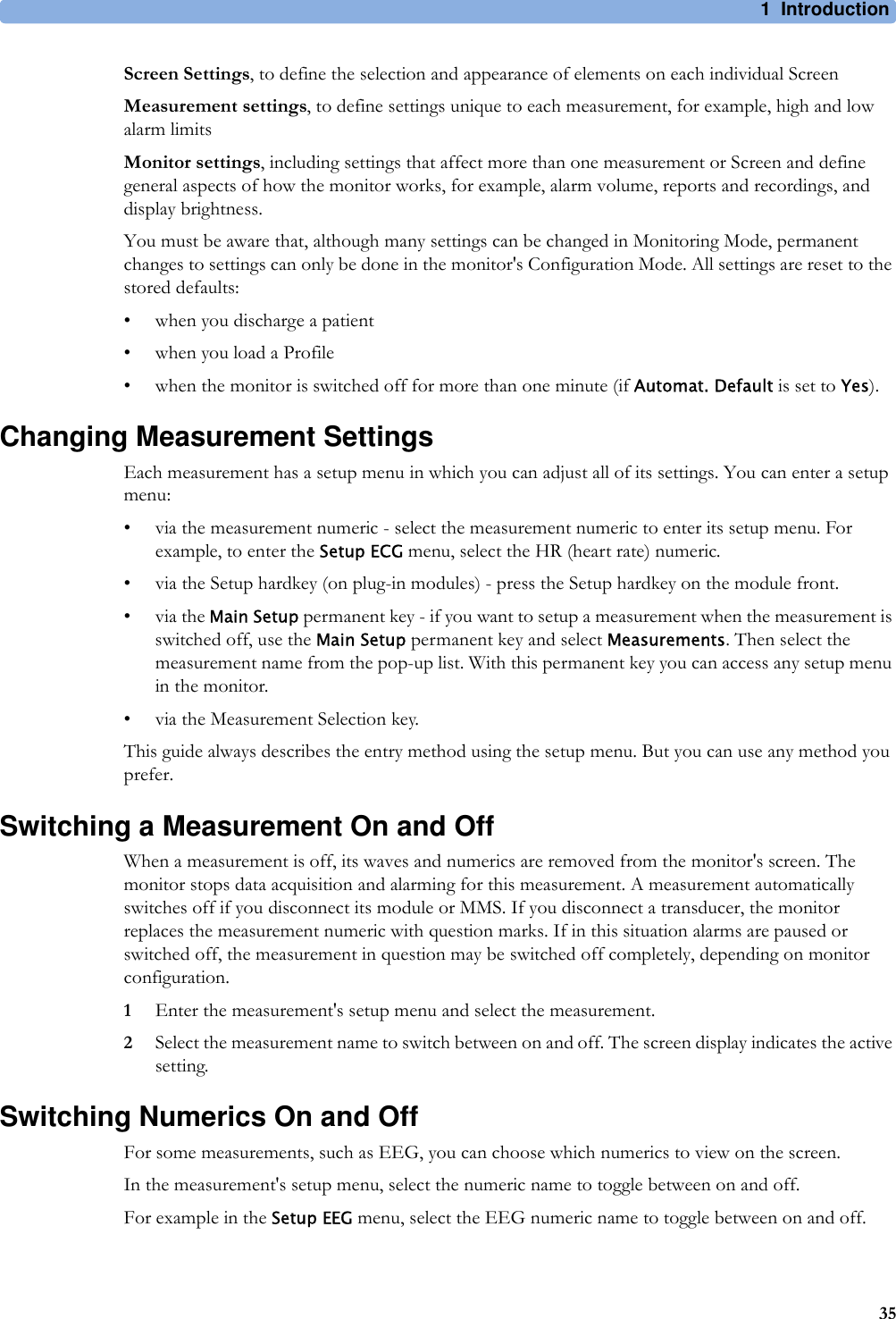
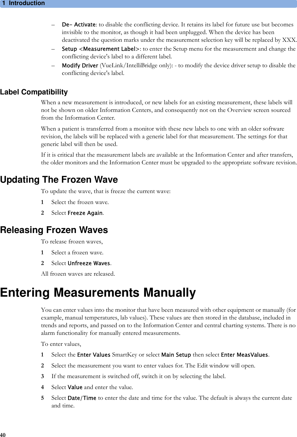
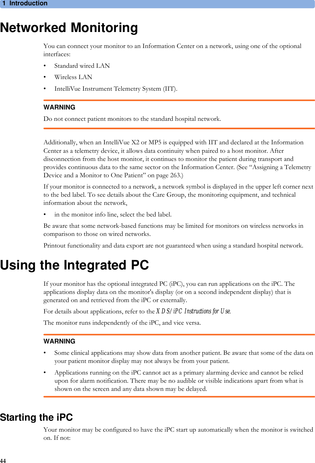
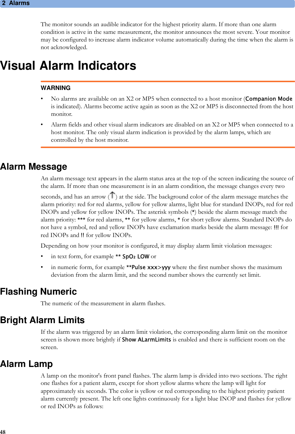
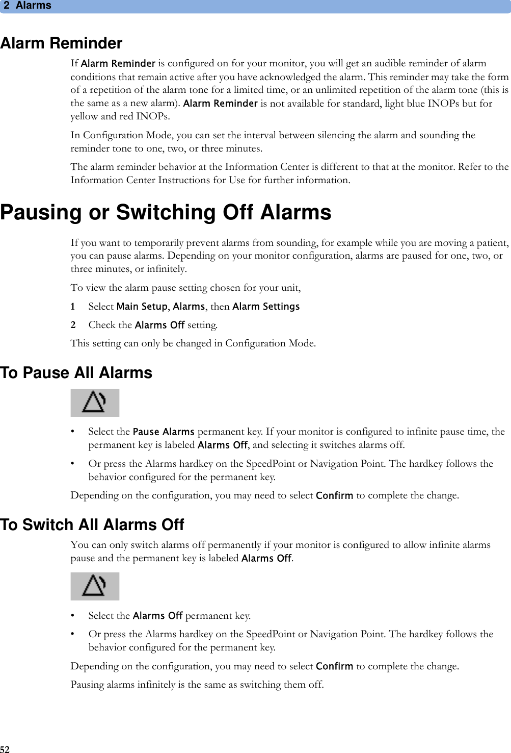
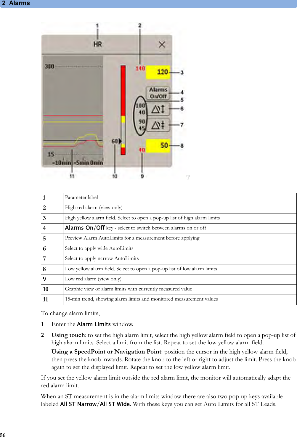
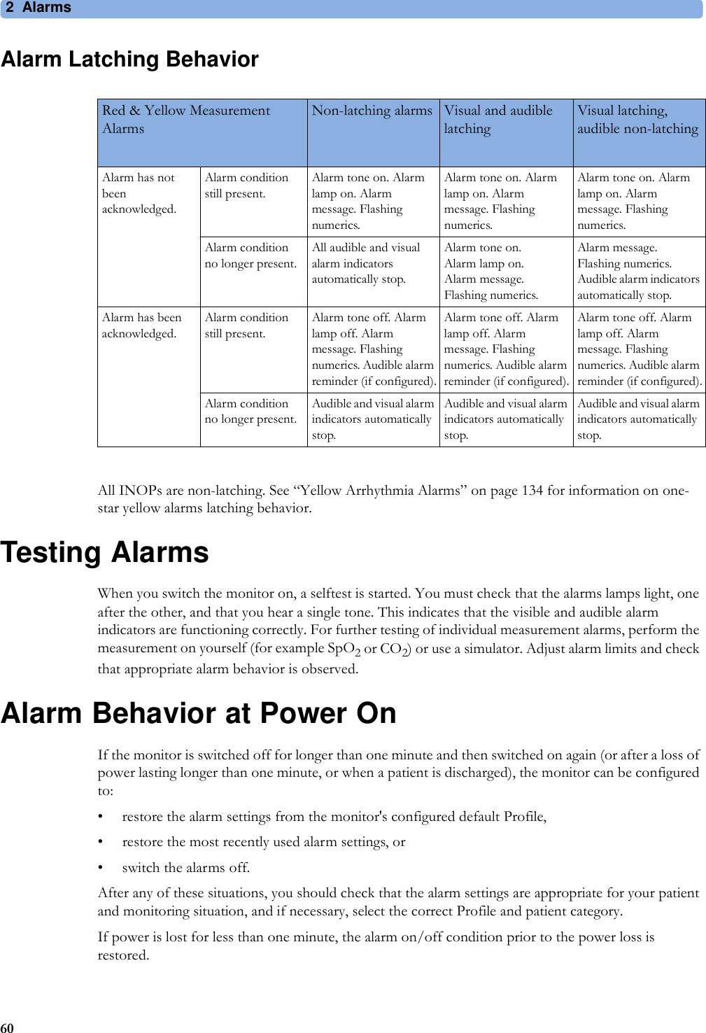
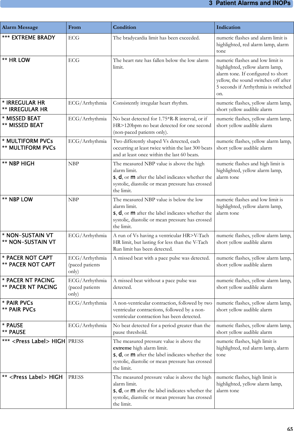
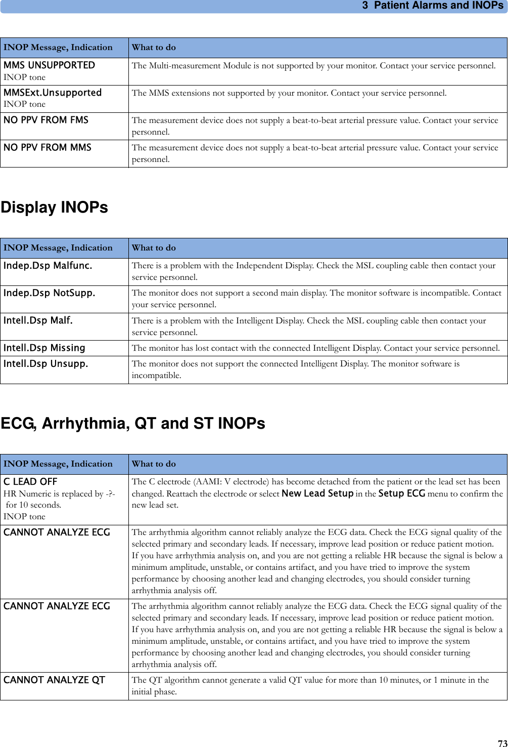
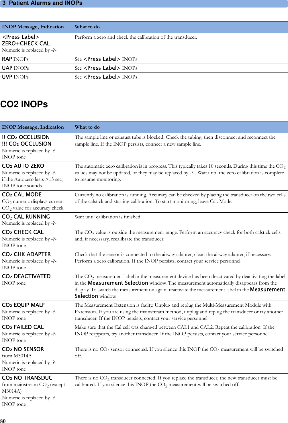
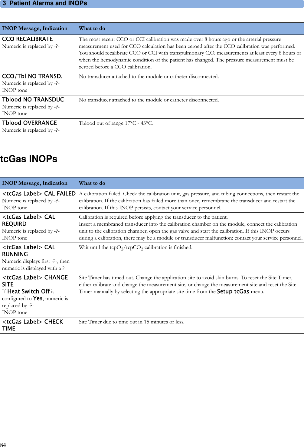
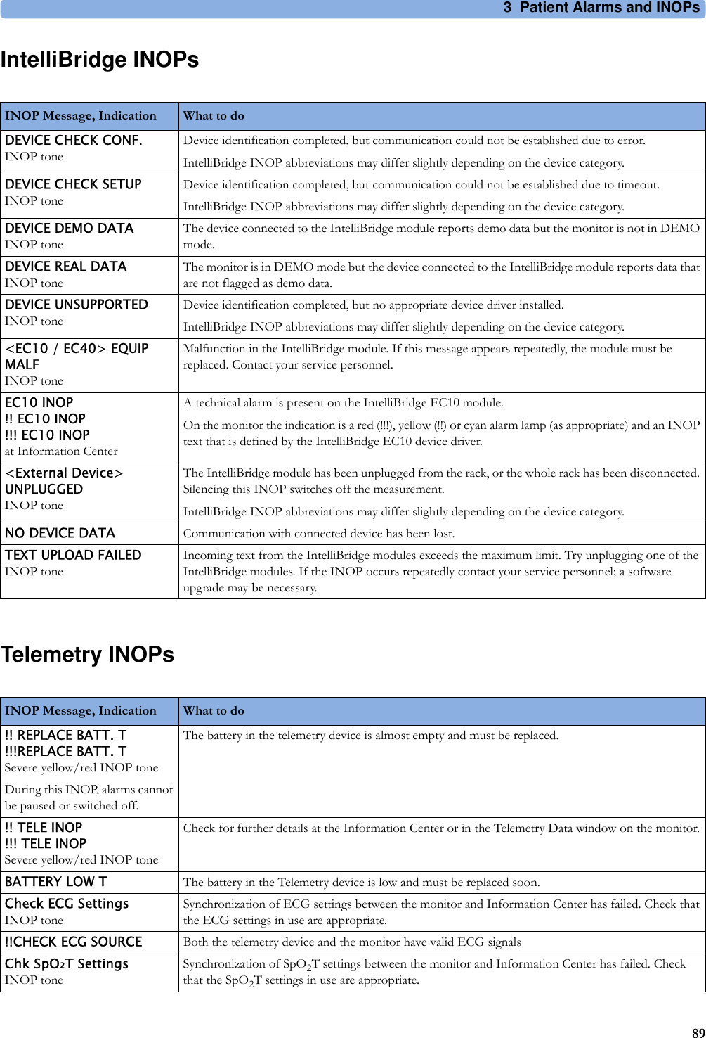
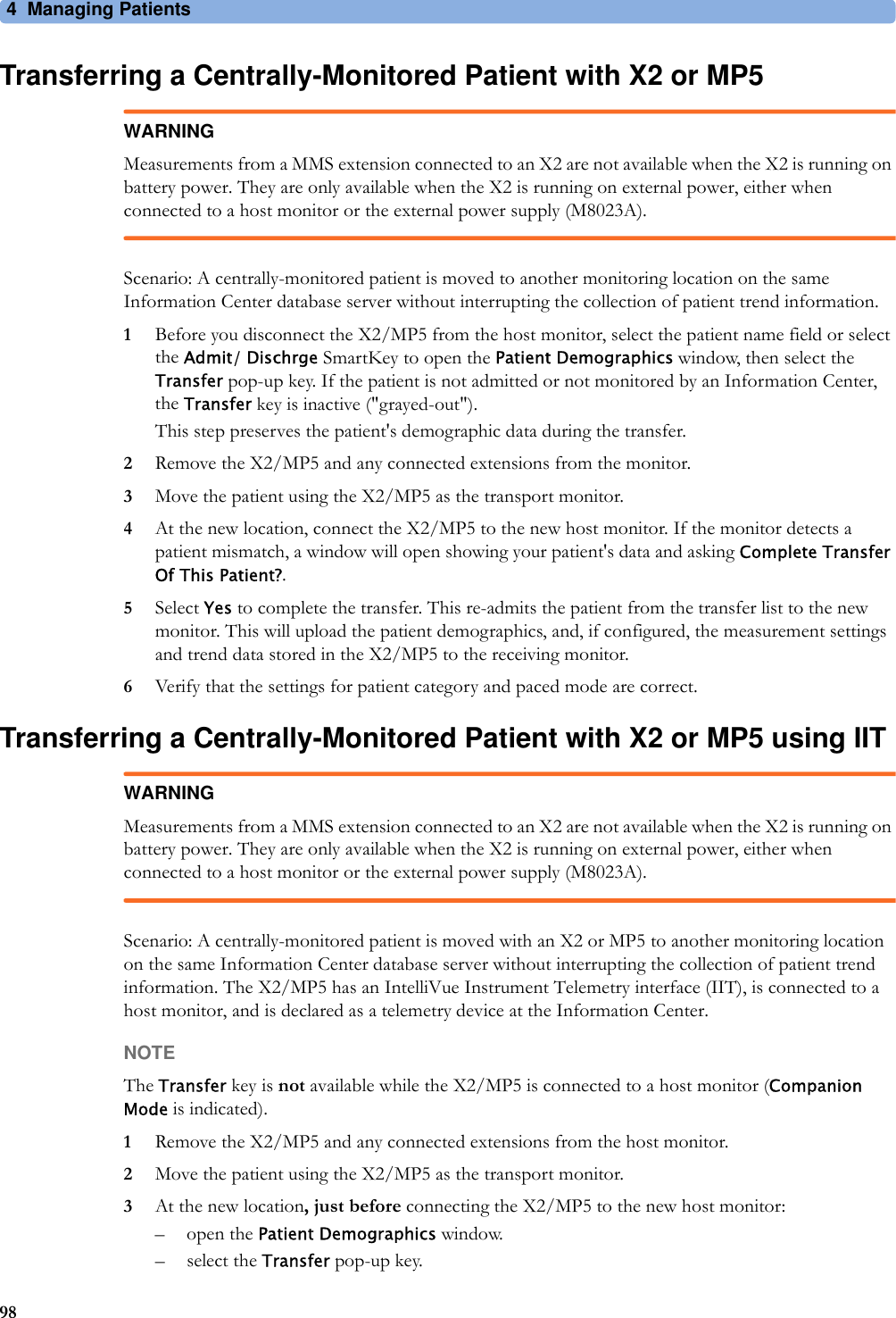
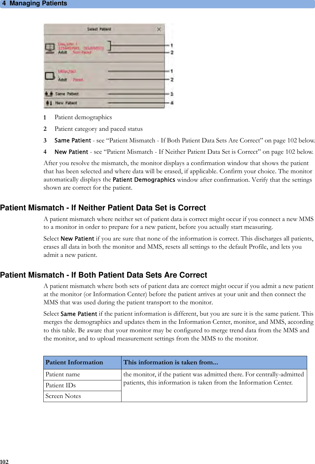
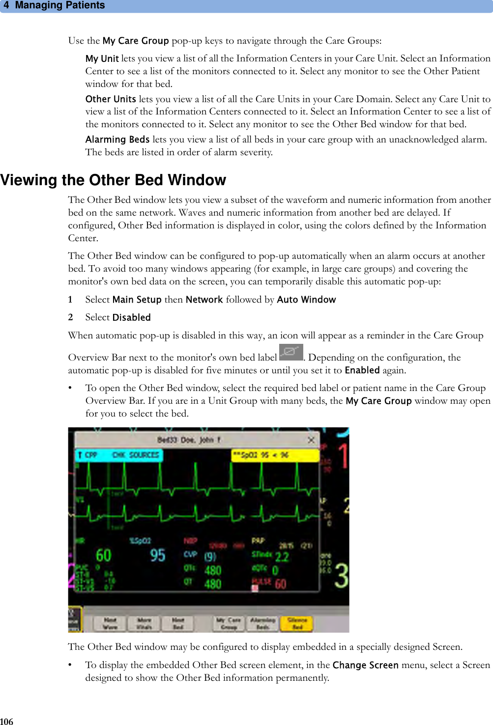
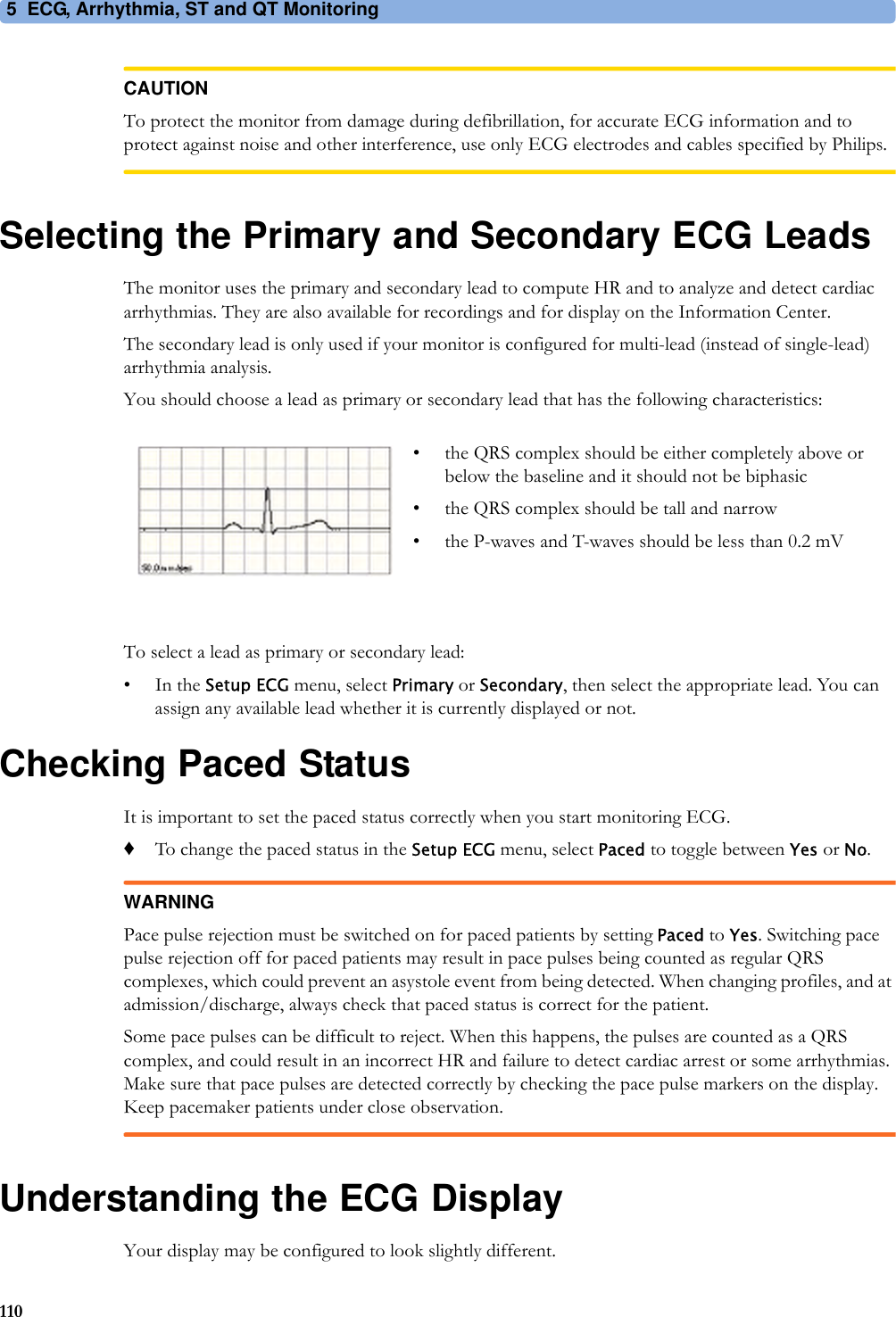
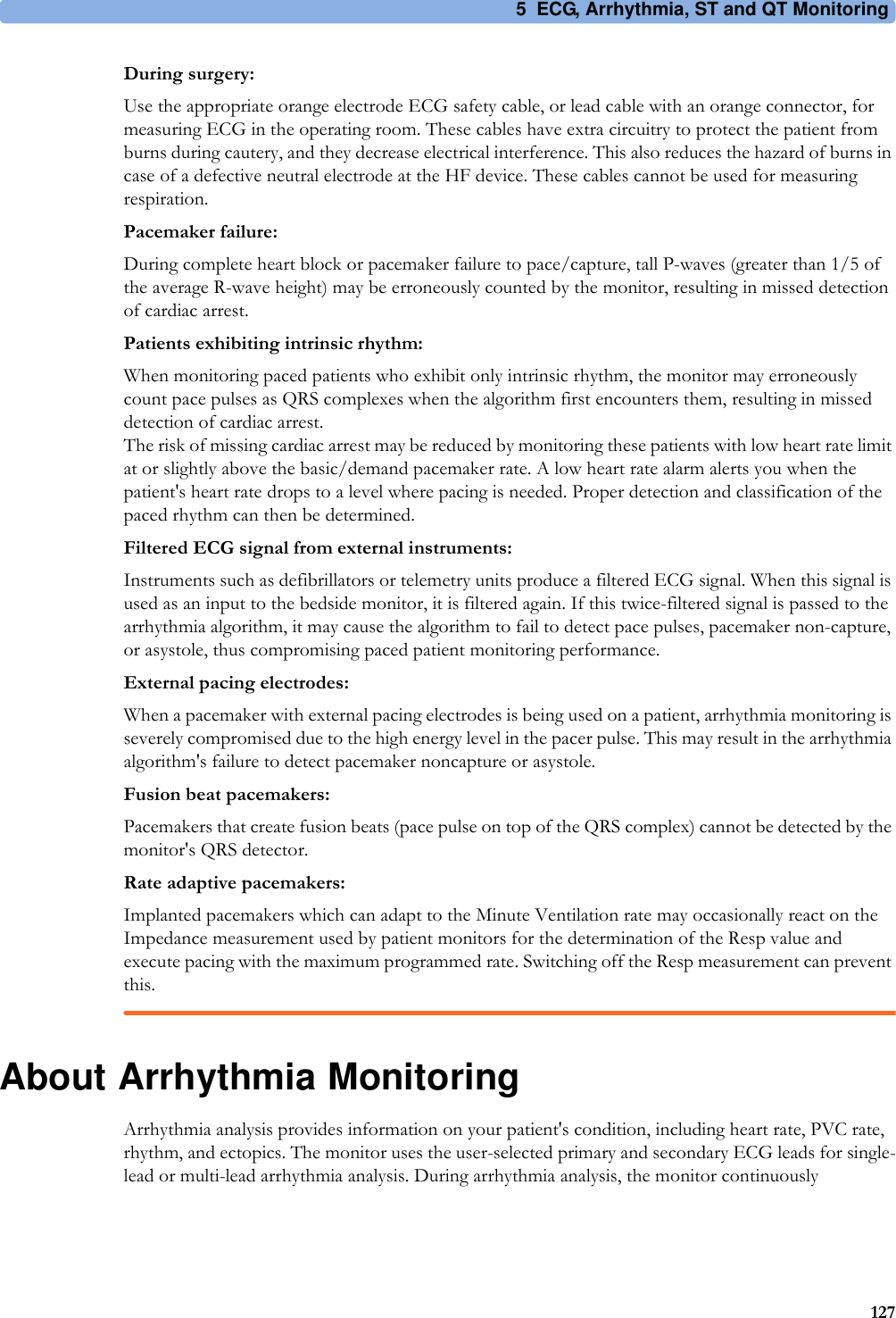
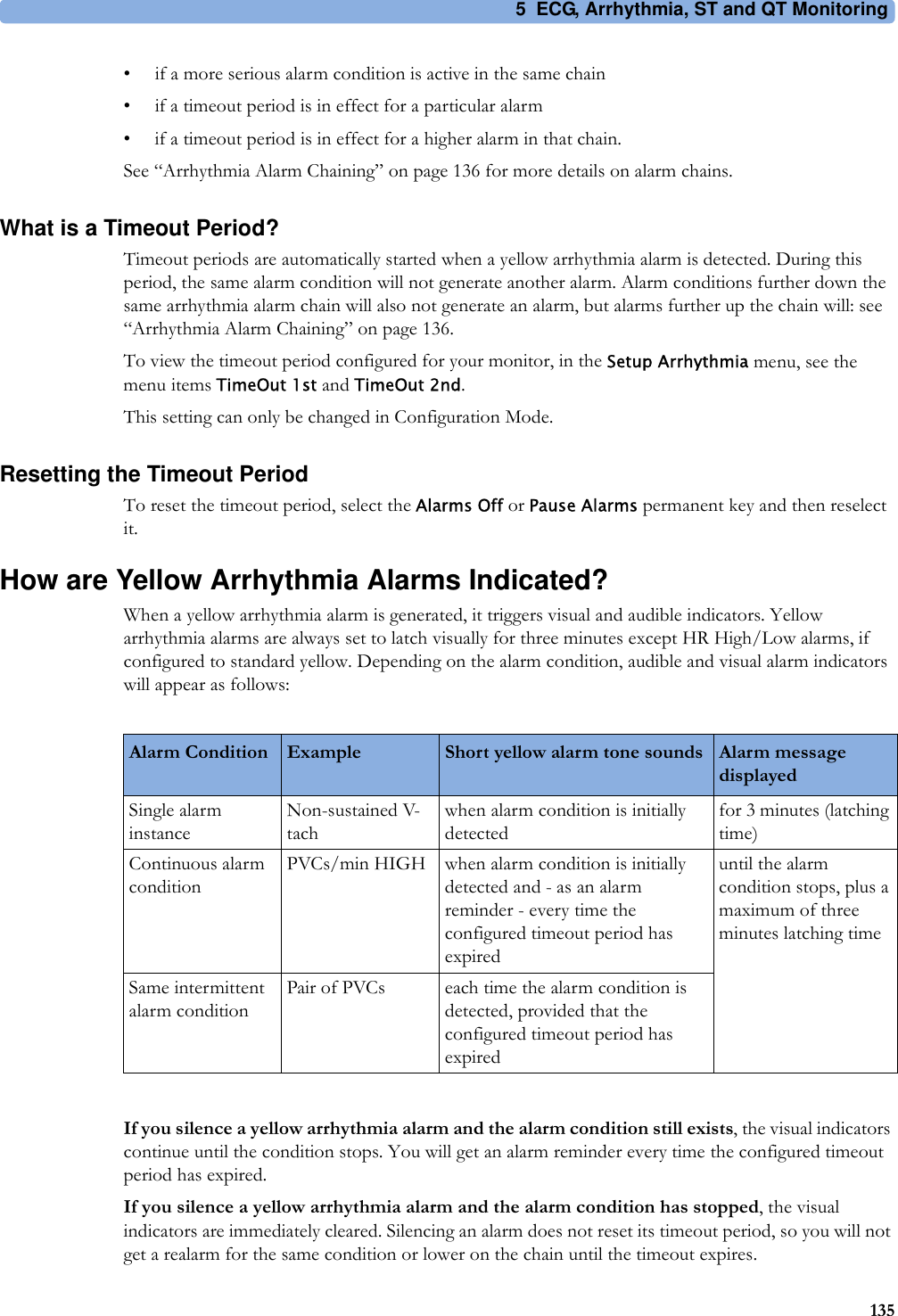
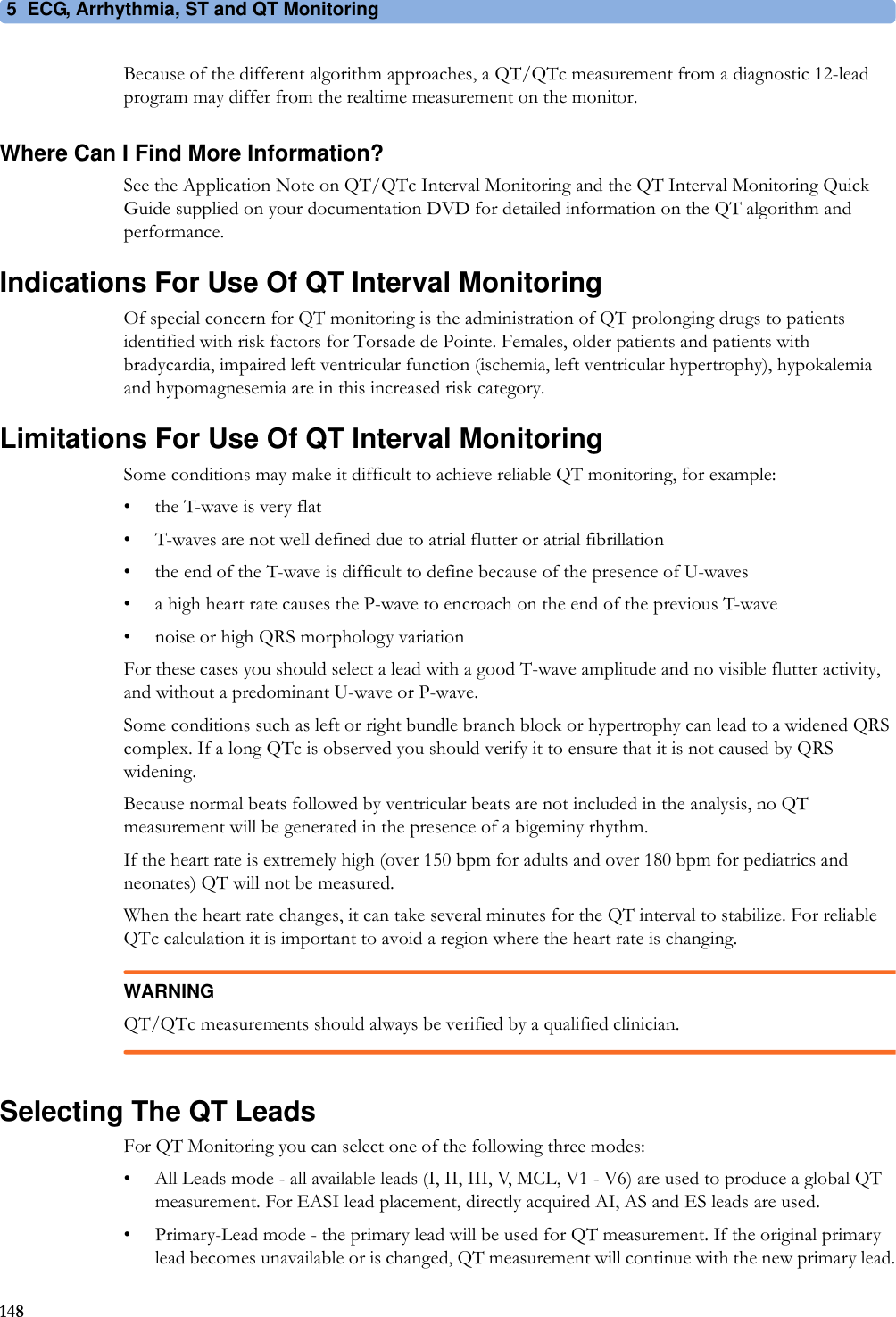
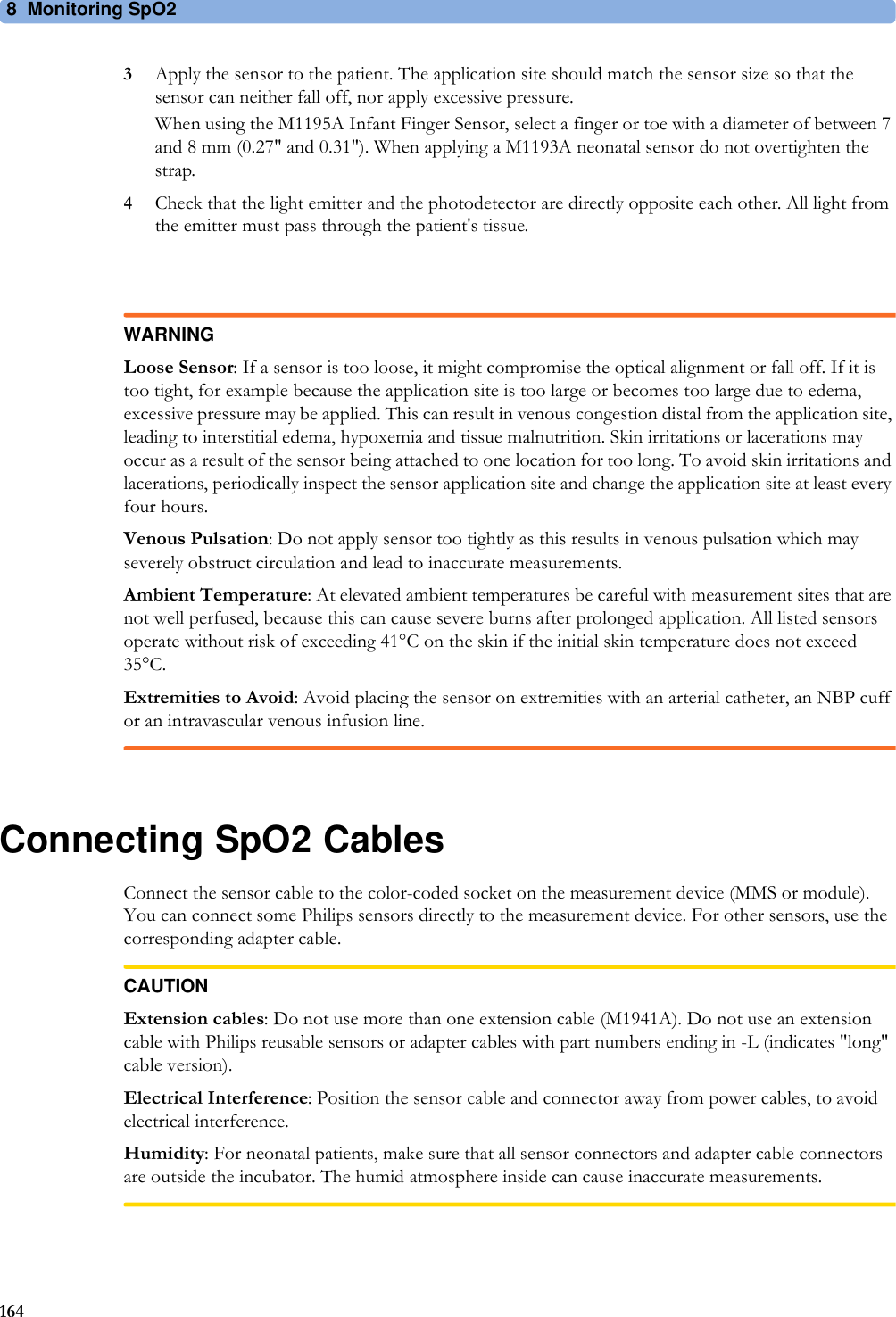
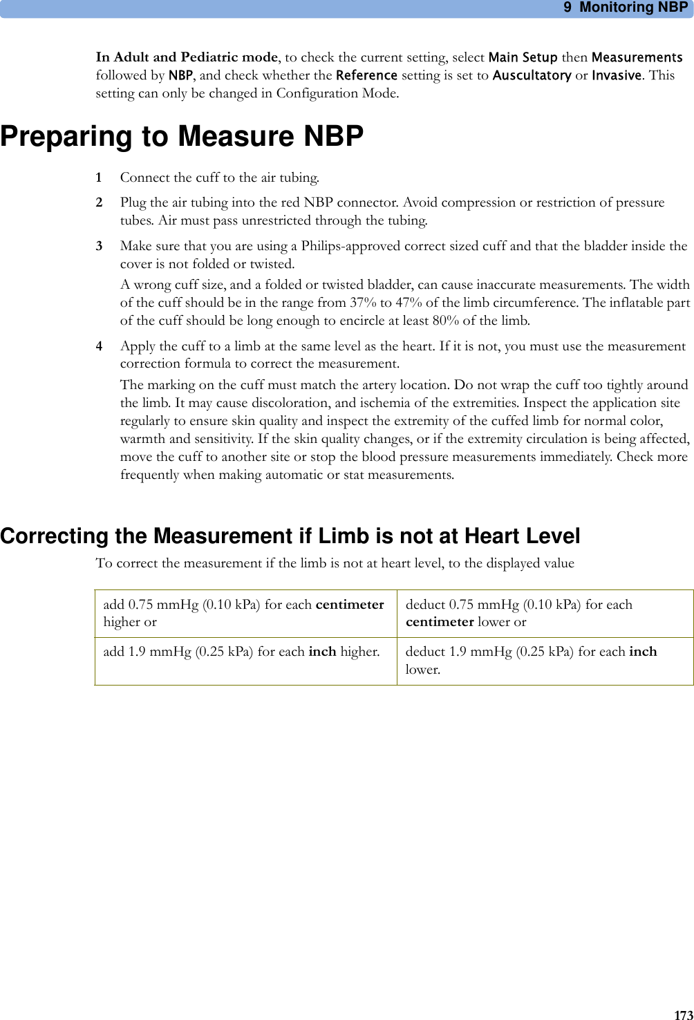
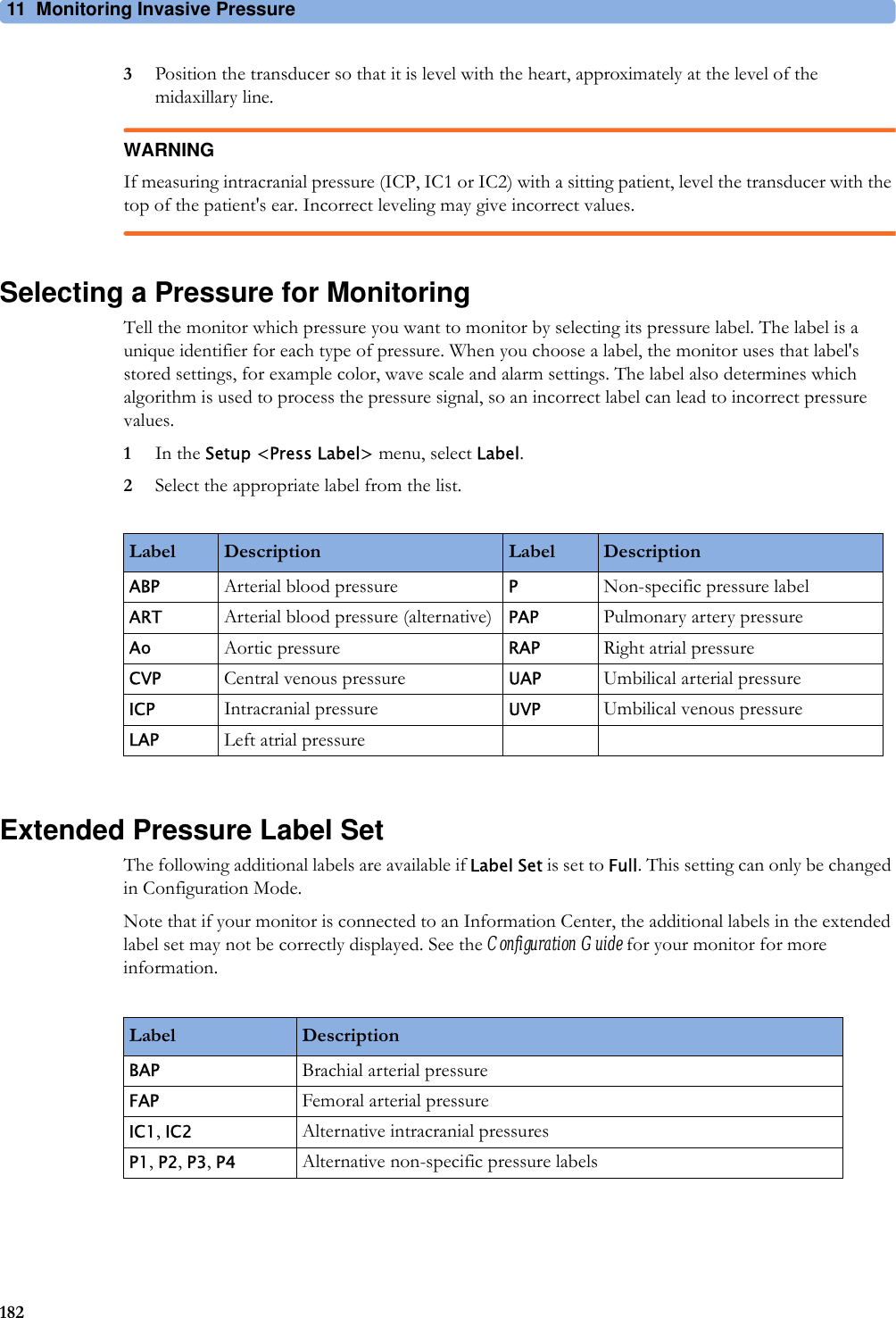
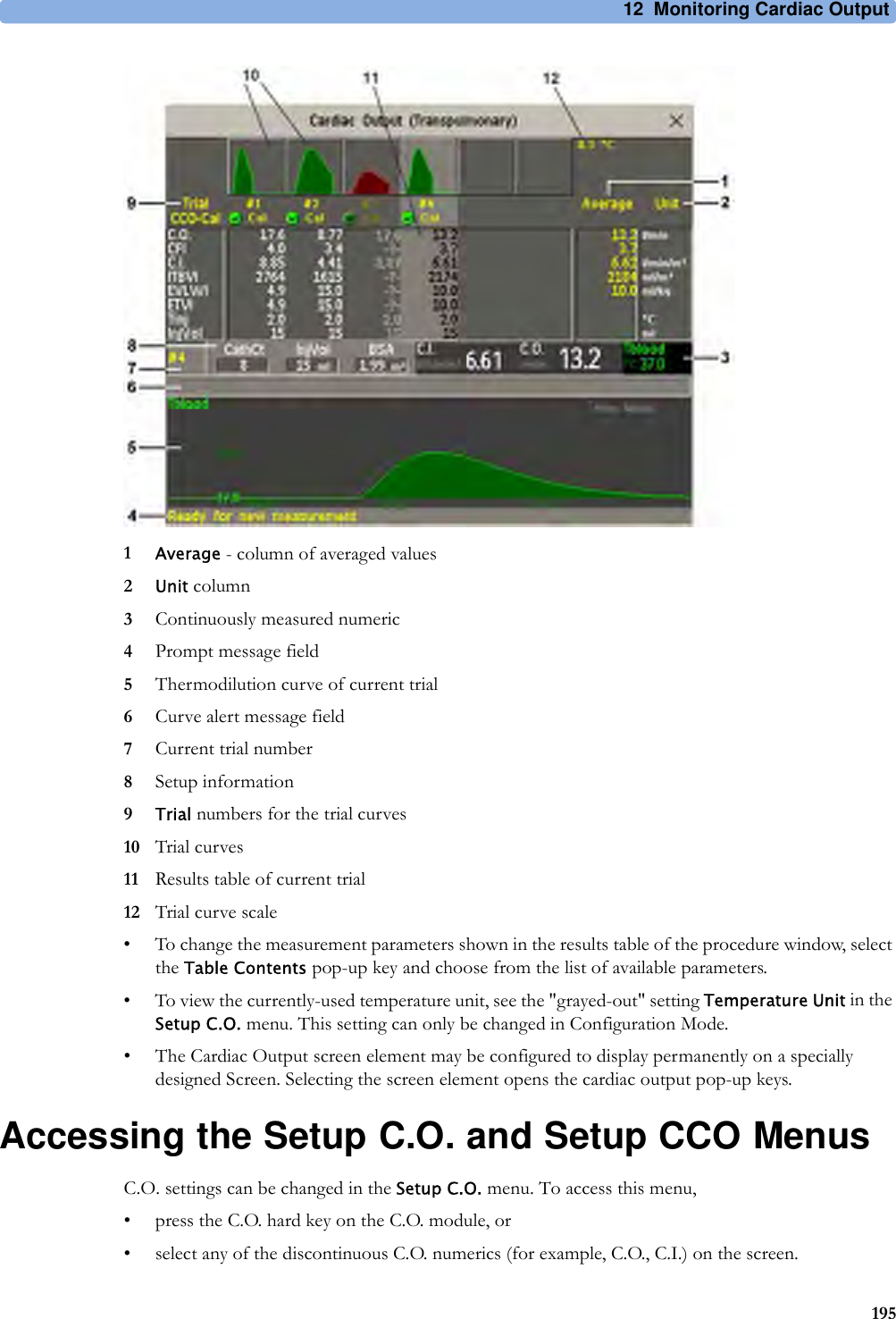
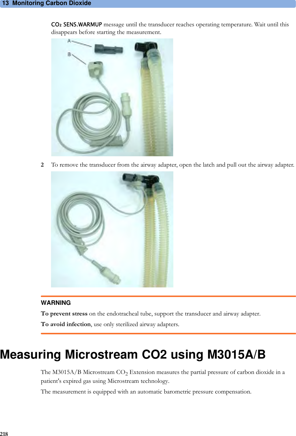
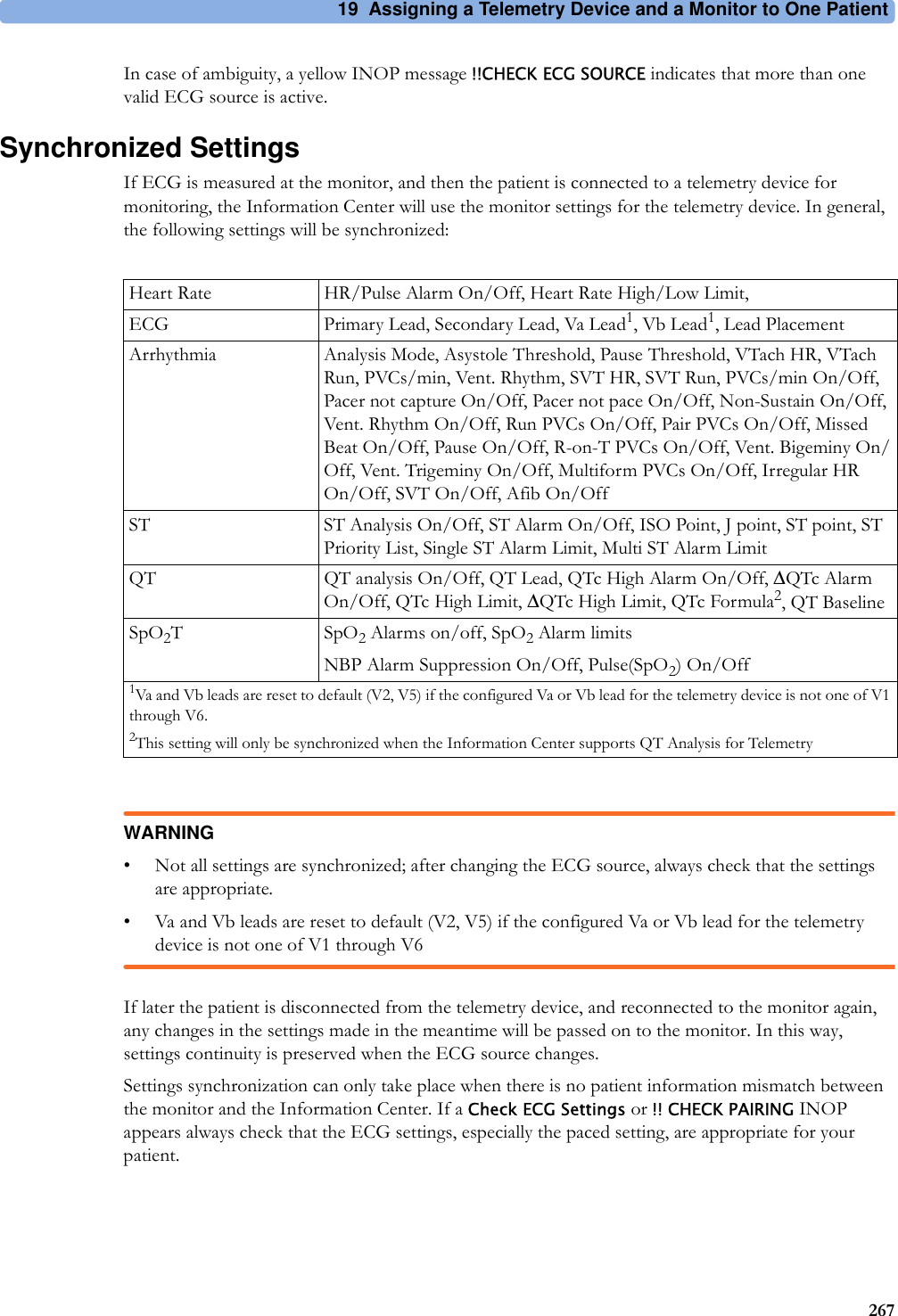
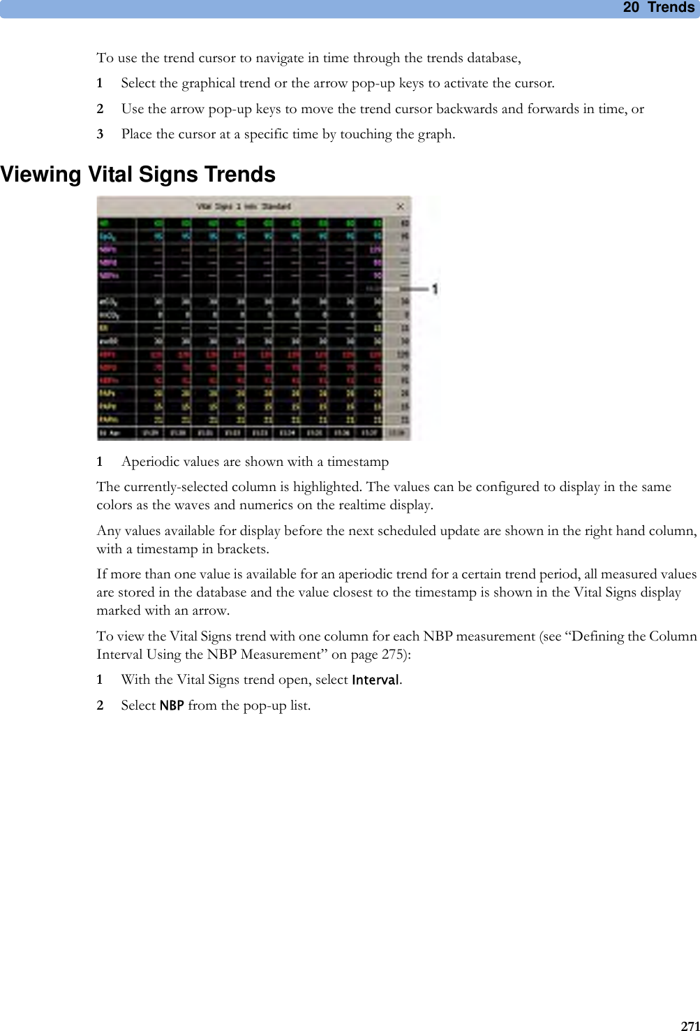
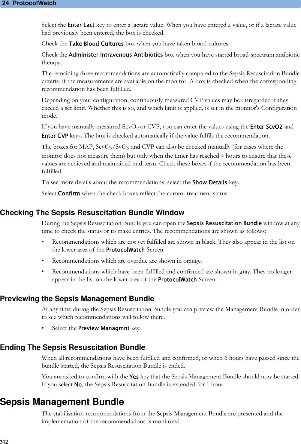
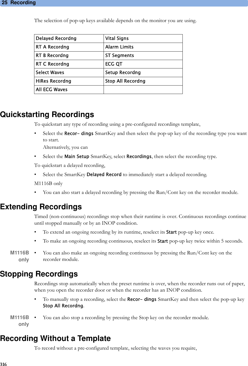
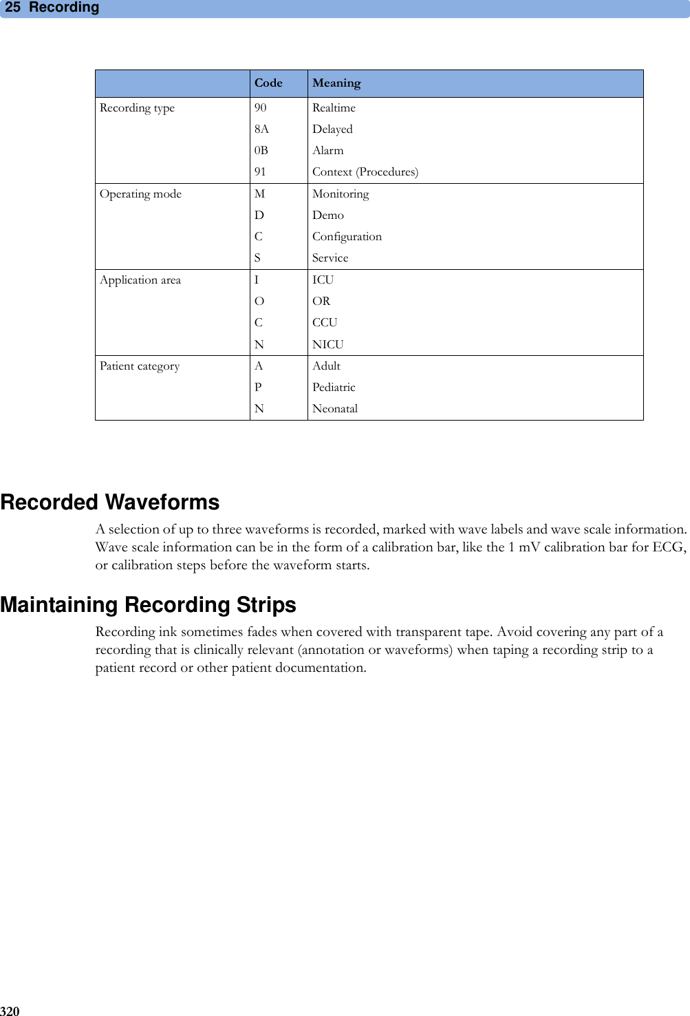
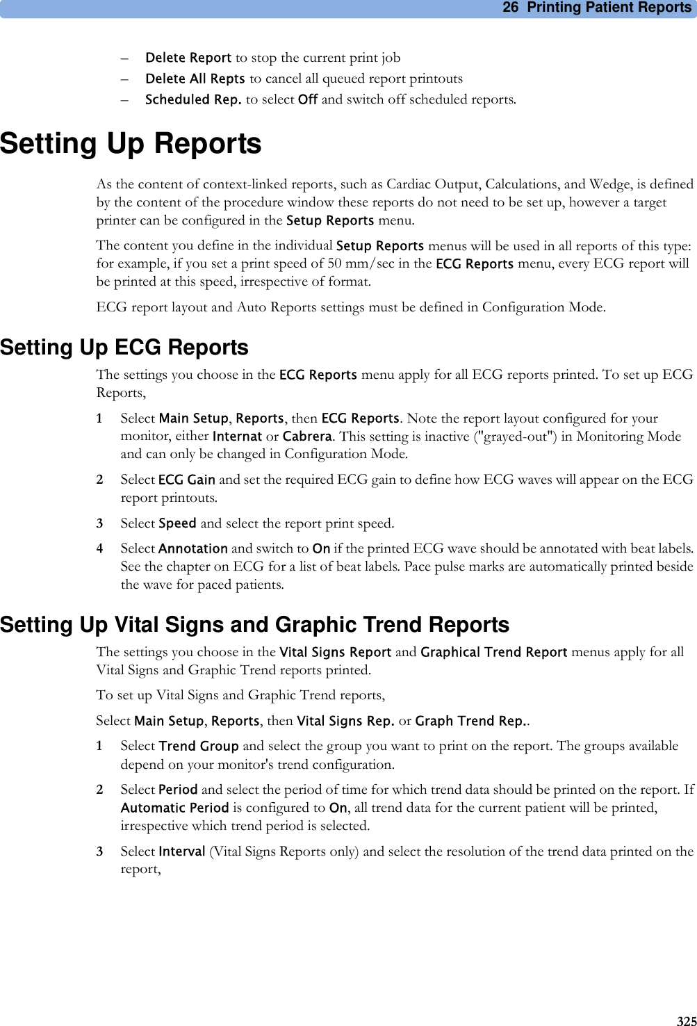
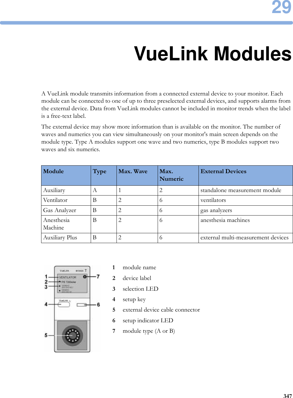
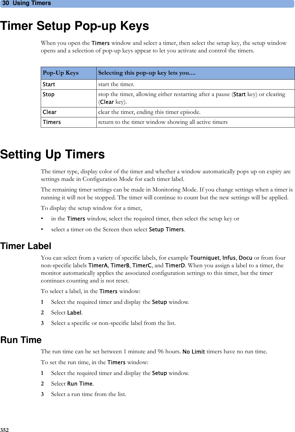
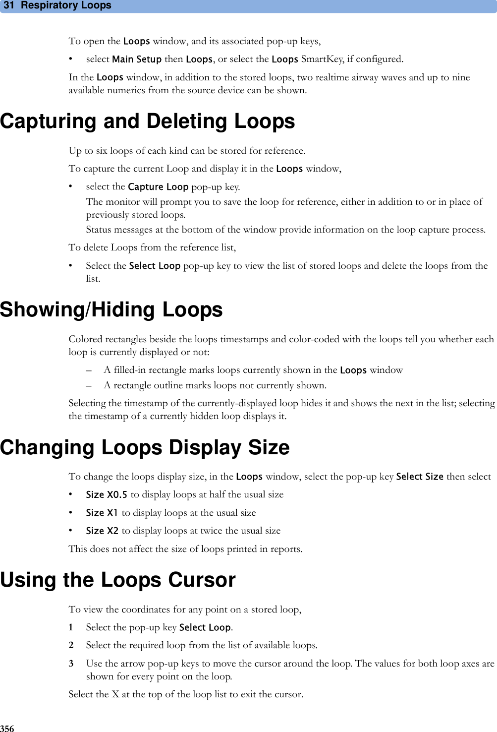
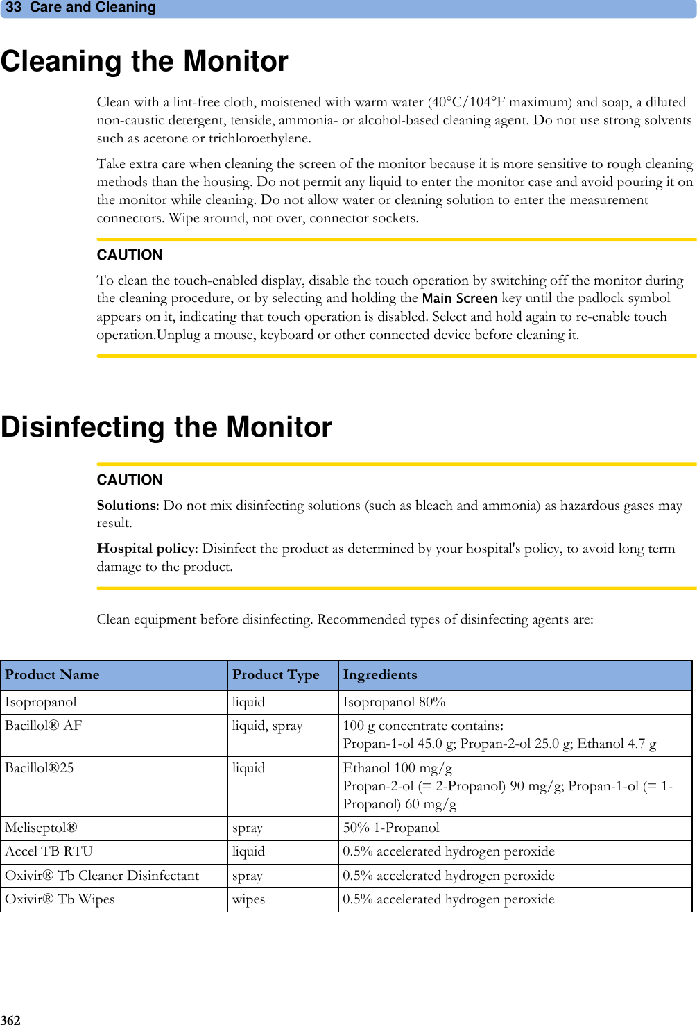
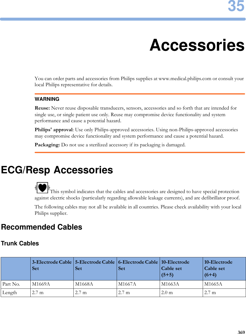
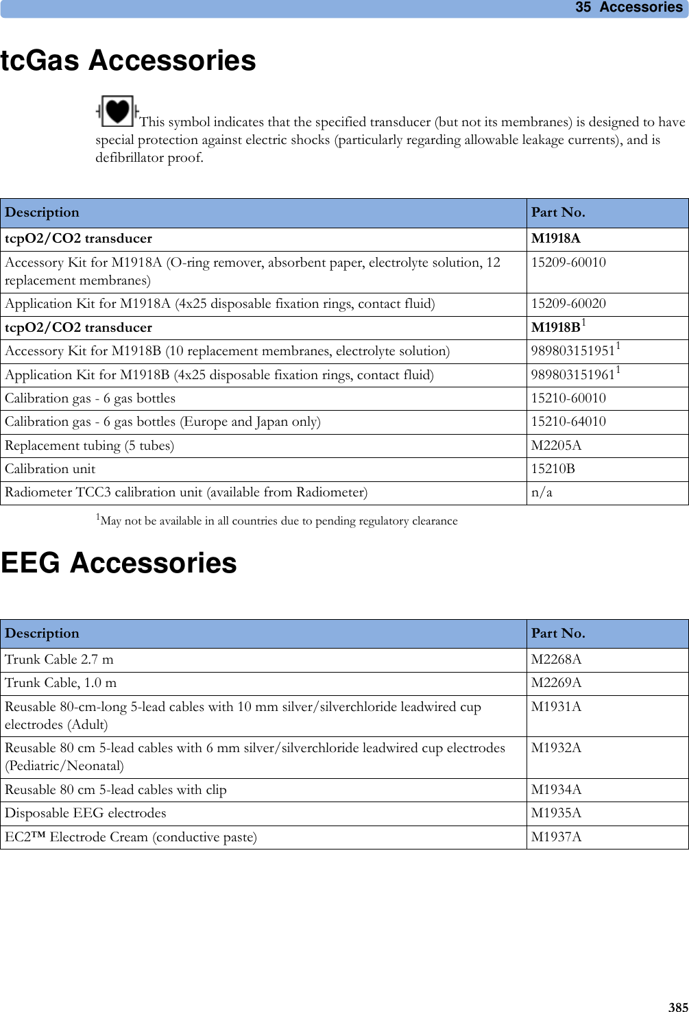
![3 Patient Alarms and INOPs76Temperature INOPsNBP DEACTIVATEDINOP toneThe NBP measurement label in the measurement device has been deactivated by deactivating the label in the Measurement Selection window. The measurement automatically disappears from the display. To switch the measurement on again, reactivate the measurement label in the Measurement Selection window.NBP EQUIP MALFNumeric is replaced by -?- INOP toneRemove the cuff from the patient. The NBP hardware is faulty. Contact your service personnel. You can silence this INOP, but the INOP message remains visible until the next measurement is started or the Stop All SmartKey is selected.NBP INTERRUPTEDNumeric is replaced by -?- INOP toneCheck the tubing and cuff for leakages or kinks. Check that you are using the correct cuff size and placement, and that the correct patient category is selected. Try restarting the measurement. If the INOP occurs repeatedly, contact your service personnel.You can silence this INOP, but the INOP message remains visible until the next measurement is started or the Stop All SmartKey is selected.This INOP arises when the measurement needed longer than the maximum time for inflation, deflation or the total measurement.NBP MEASURE FAILEDNumeric may be displayed with a -?- INOP toneCheck that you are using the correct cuff size and placement, and that the correct patient category is selected. Try restarting the measurement.You can silence this INOP, but the INOP message remains visible until the next measurement is started or the Stop All SmartKey is selected.Check the condition and suitability of the patient for NBP monitoring. Use another cuff to continue measuring.INOP Message, Indication What to do INOP Message, Indication What to do T1, T2, T3, T4 INOPs See <Temp Label> INOPsTamb INOPs See <Temp Label> INOPsTart INOPs See <Temp Label> INOPsTcereb INOPs See <Temp Label> INOPsTcore INOPs See <Temp Label> INOPs<Temp Label> DEACTIVATEDINOP toneA Temp measurement label in the measurement device has been deactivated, either by connecting a Pressure transducer in the shared Press/Temp socket, or by deactivating the label in the Measurement Selection window.The measurement automatically disappears from the display.To switch the measurement on again, either reconnect a Temp transducer or reactivate the measurement label in the Measurement Selection window.<Temp Label> EQUIP MALFNumeric is replaced by -?-INOP toneContact your service personnel.The temperature hardware is faulty.<Temp Label> NO TRANSDUCNumeric is replaced by -?-INOP toneMake sure the TEMP probe is connected to the MMS or module.If you silence this INOP, the measurement will be switched off.<Temp Label> OVERRANGENumeric is replaced by -?-INOP toneTry changing the application site of the transducer.[The temperature is less than -1°C, or greater than 45°C.]](https://usermanual.wiki/Philips-Medical-Systems-North-America/SRRBV2.User-Manual-Olympus/User-Guide-1340937-Page-76.png)
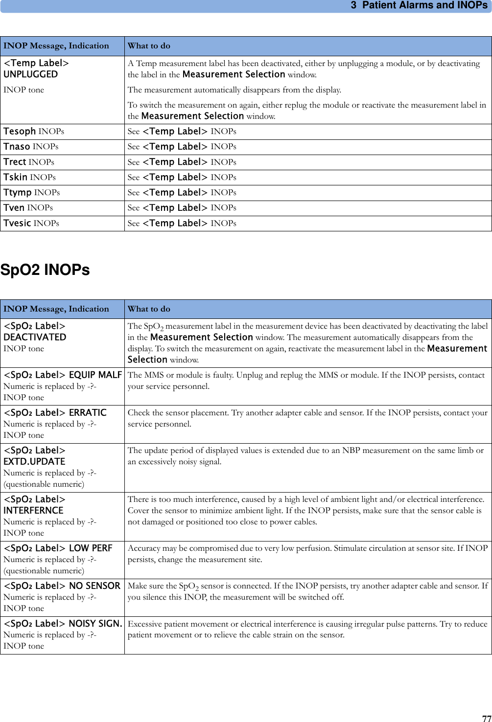
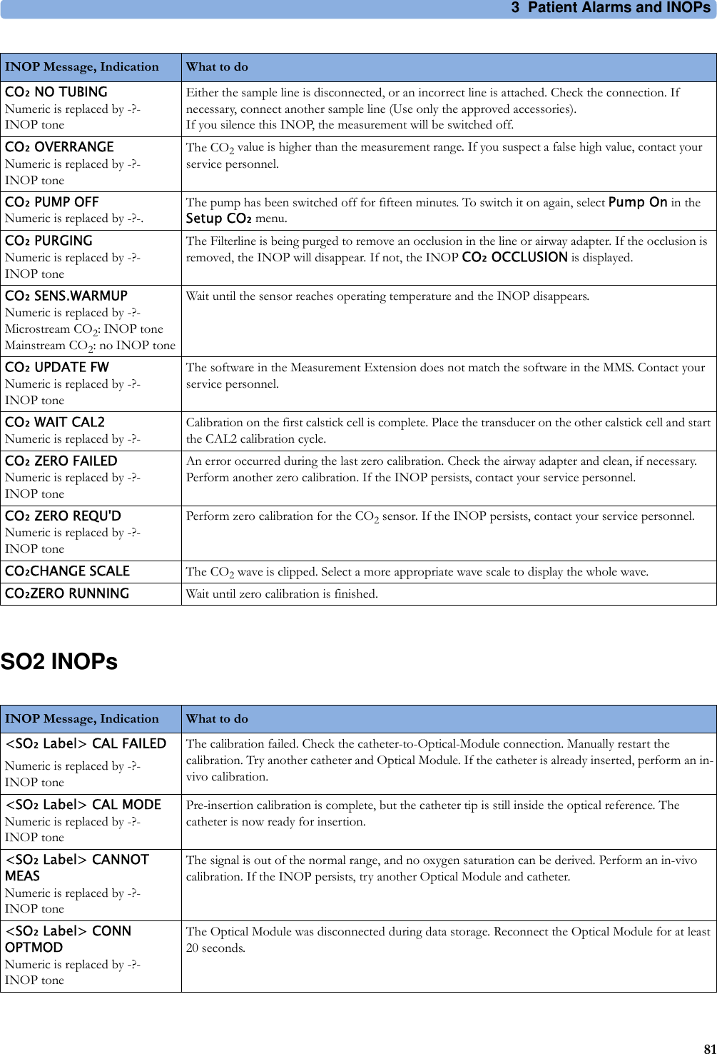
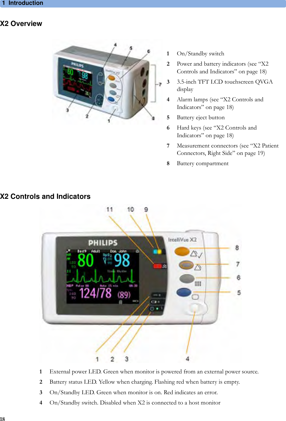
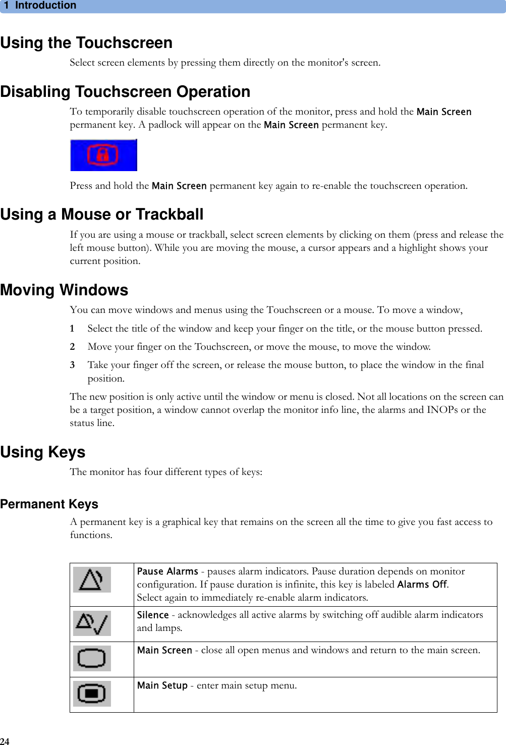
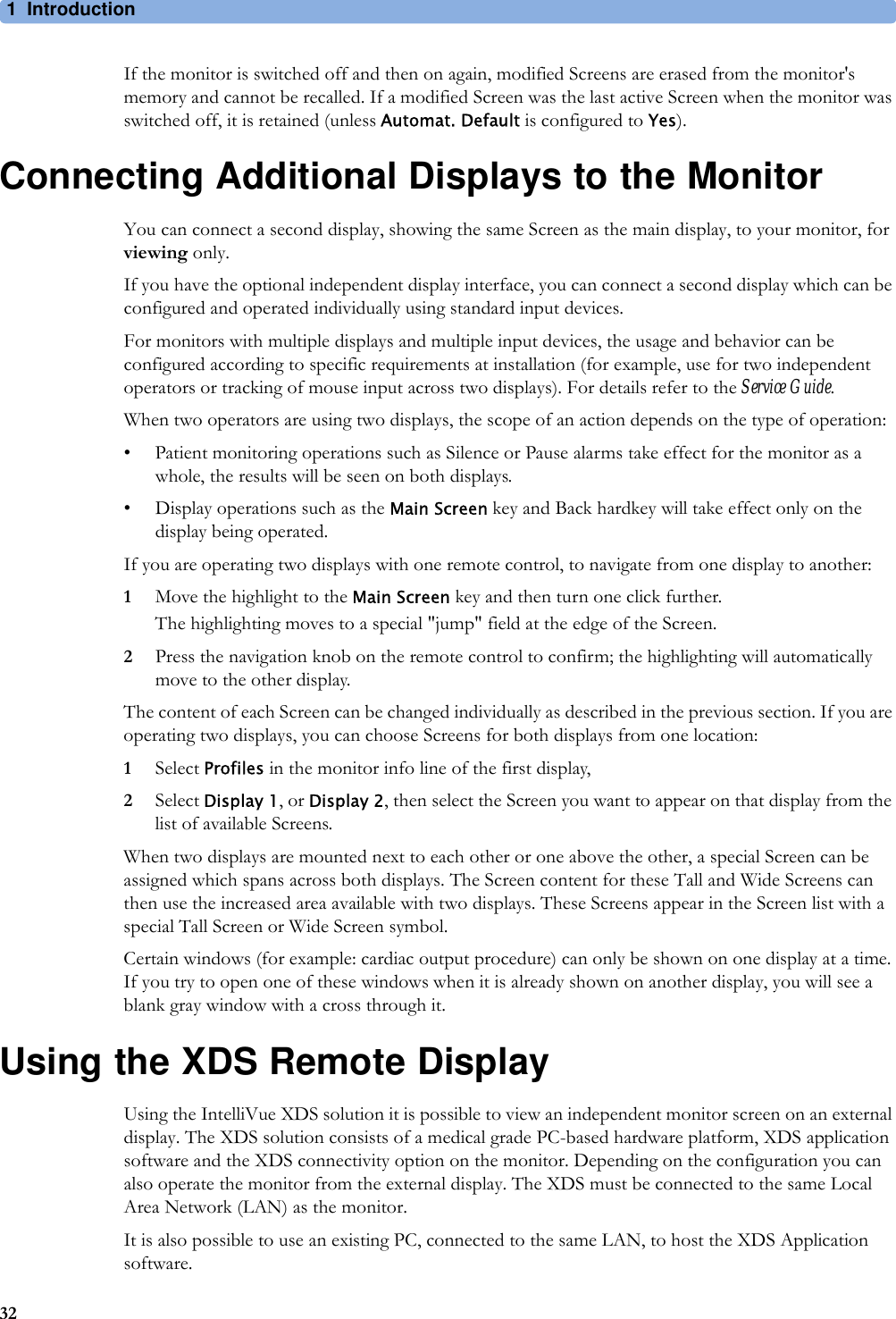
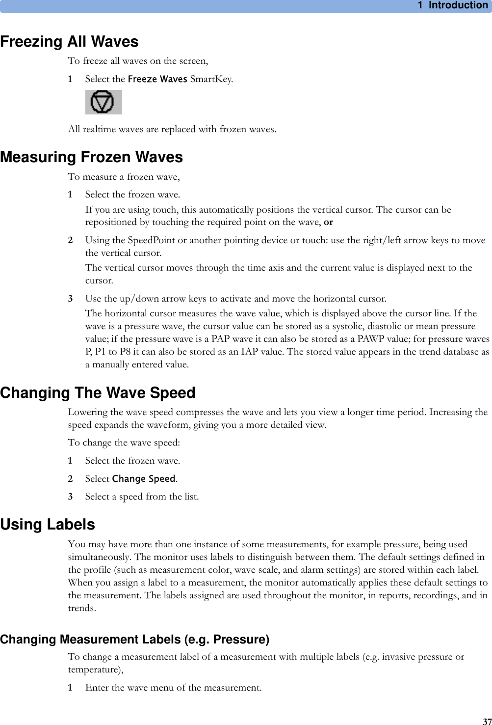
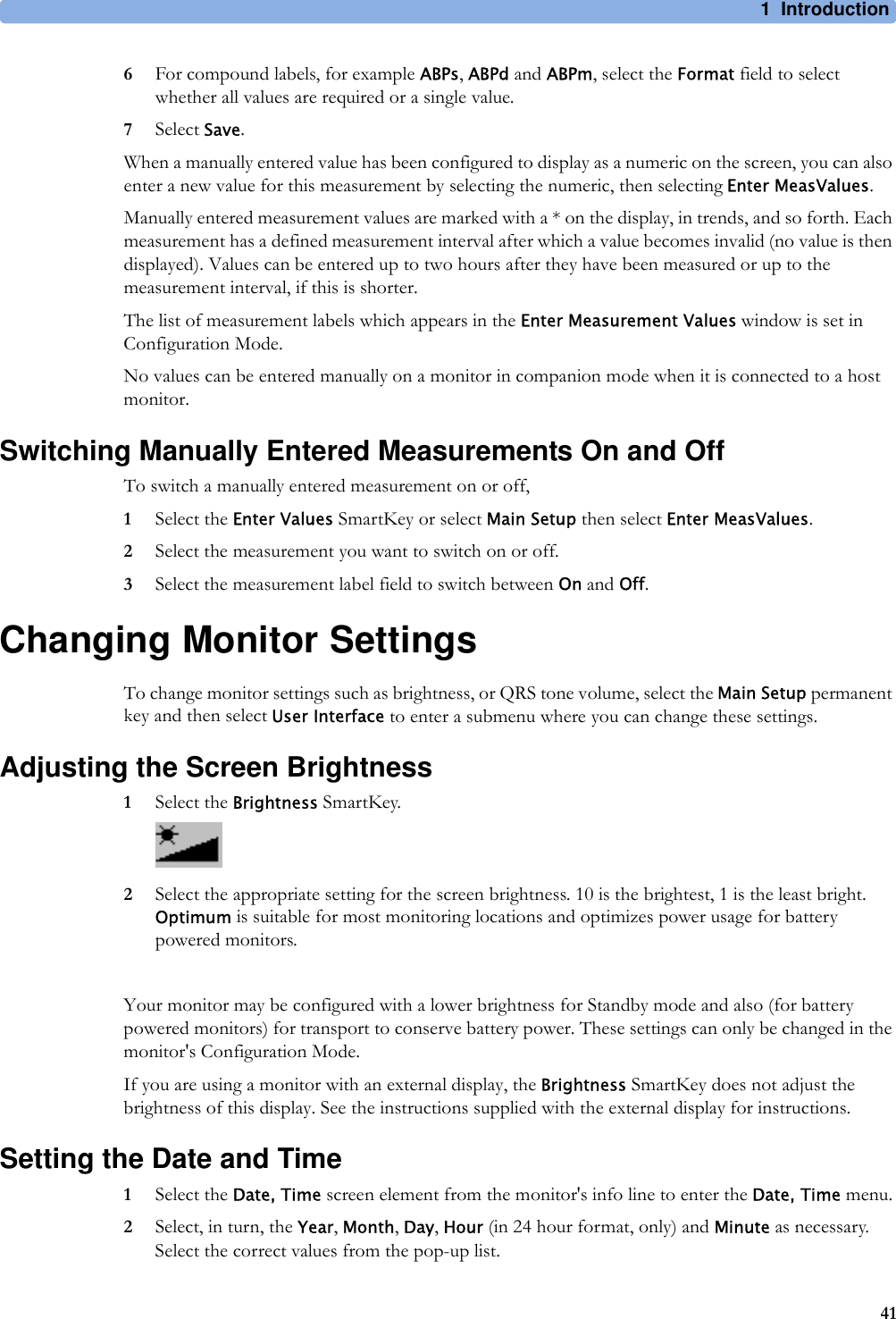
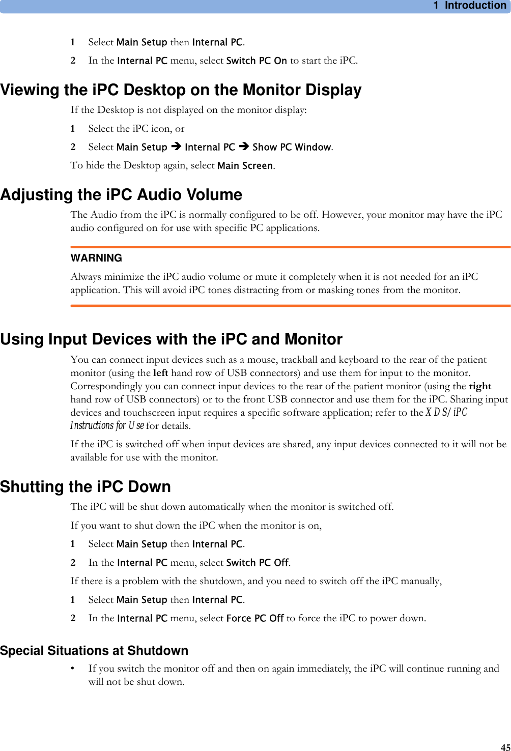
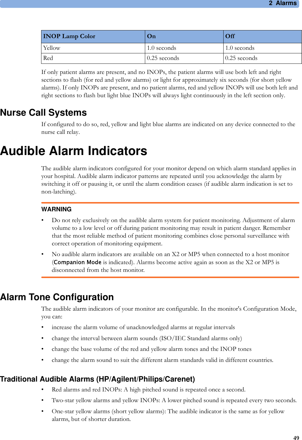
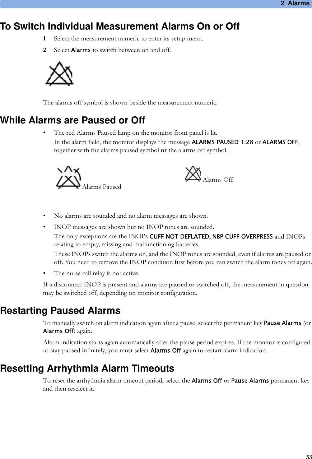
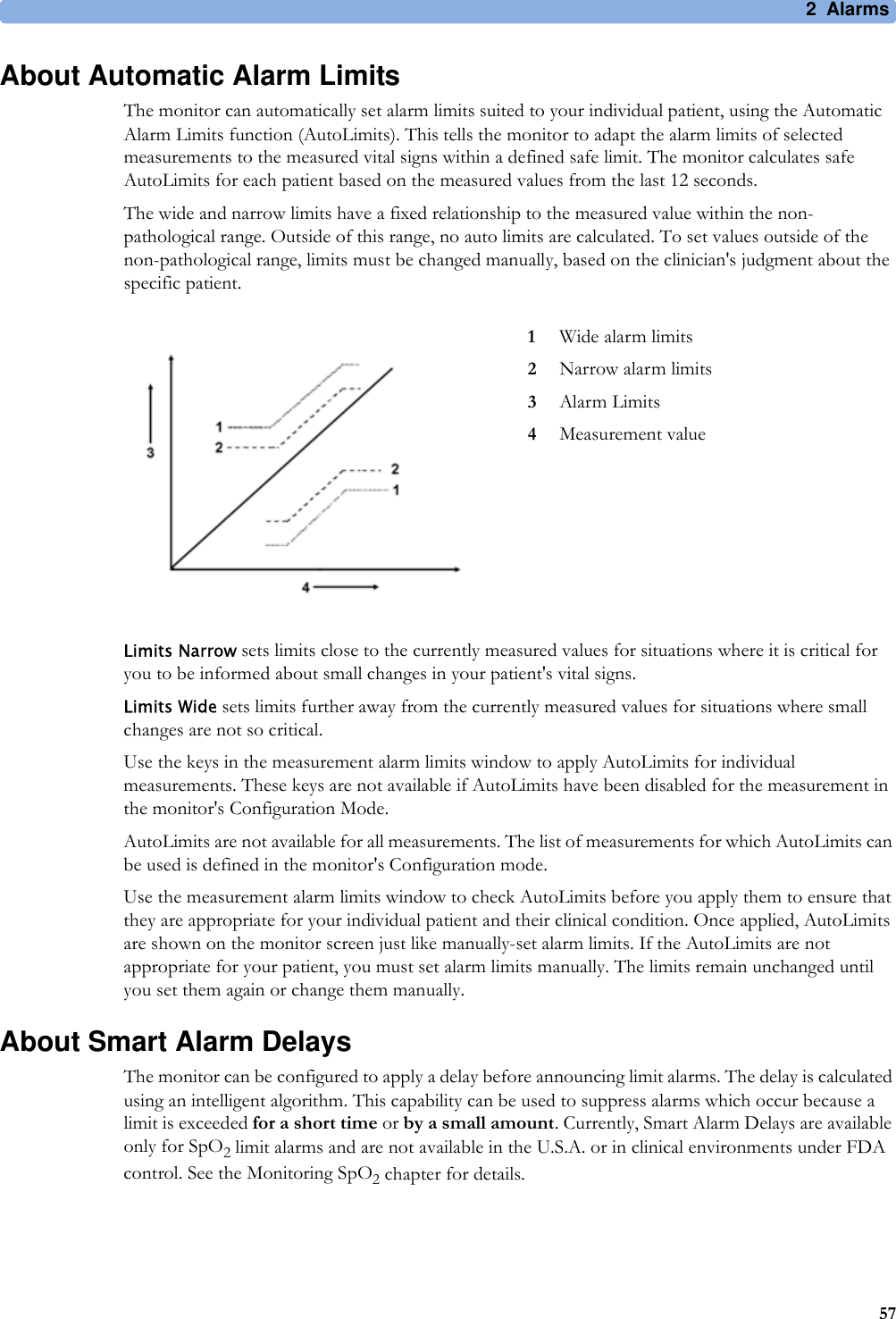
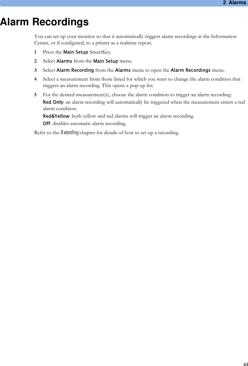
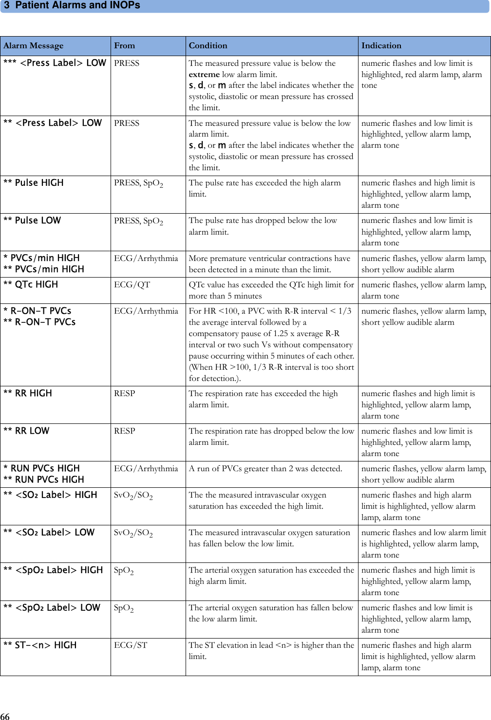
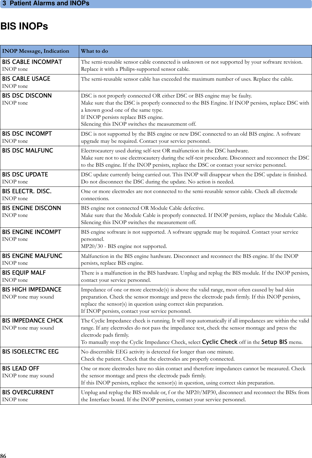
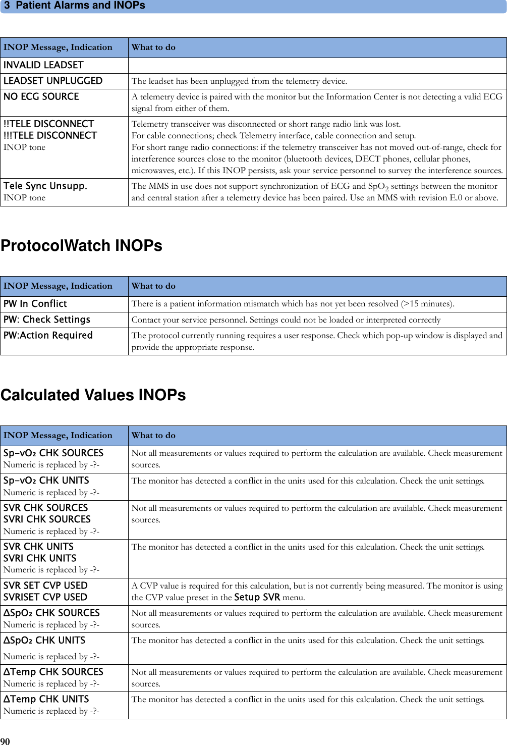
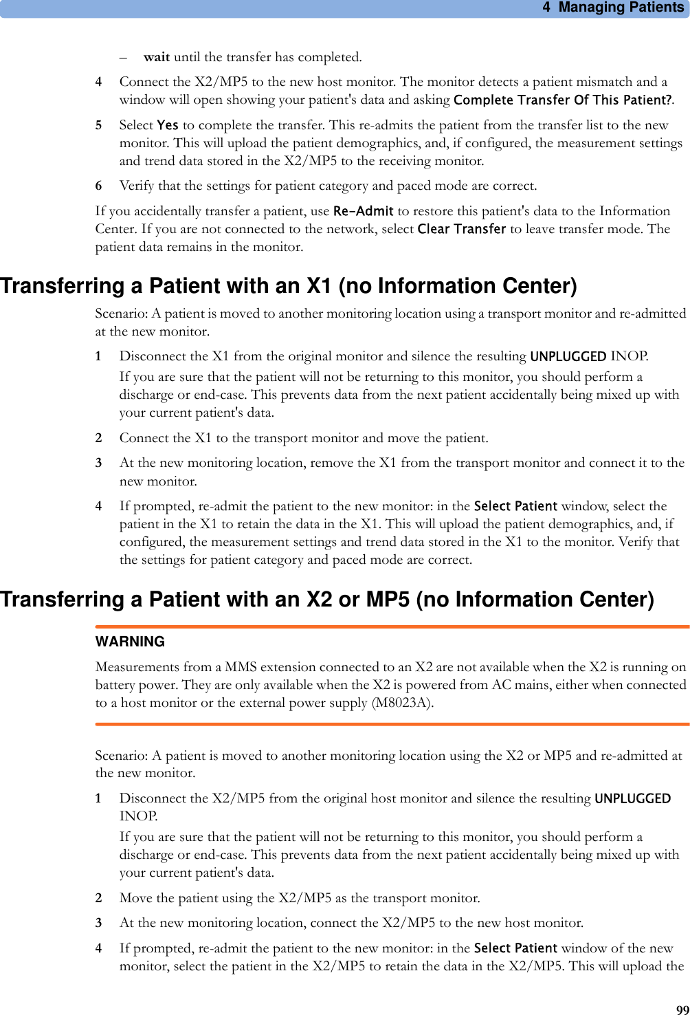
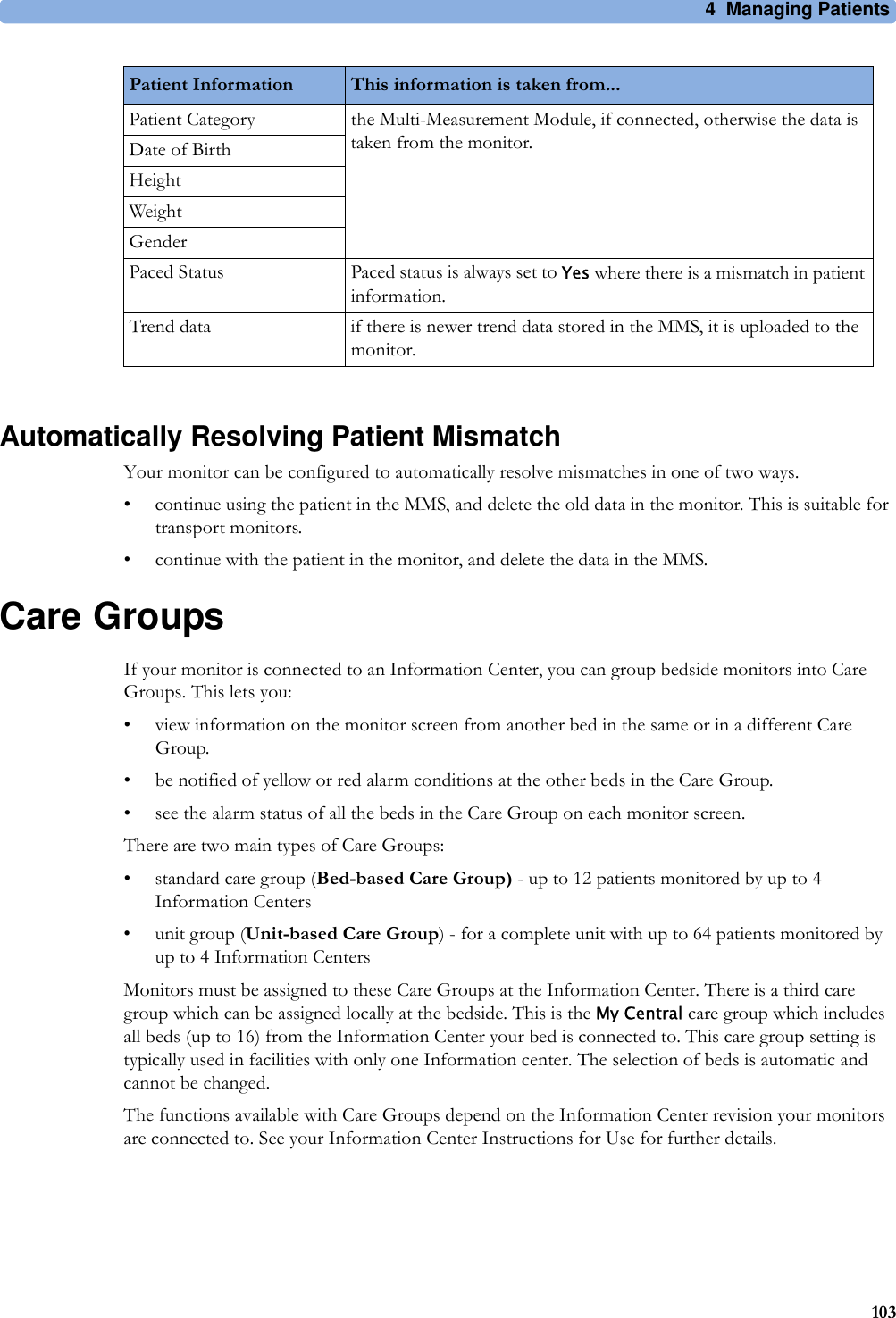
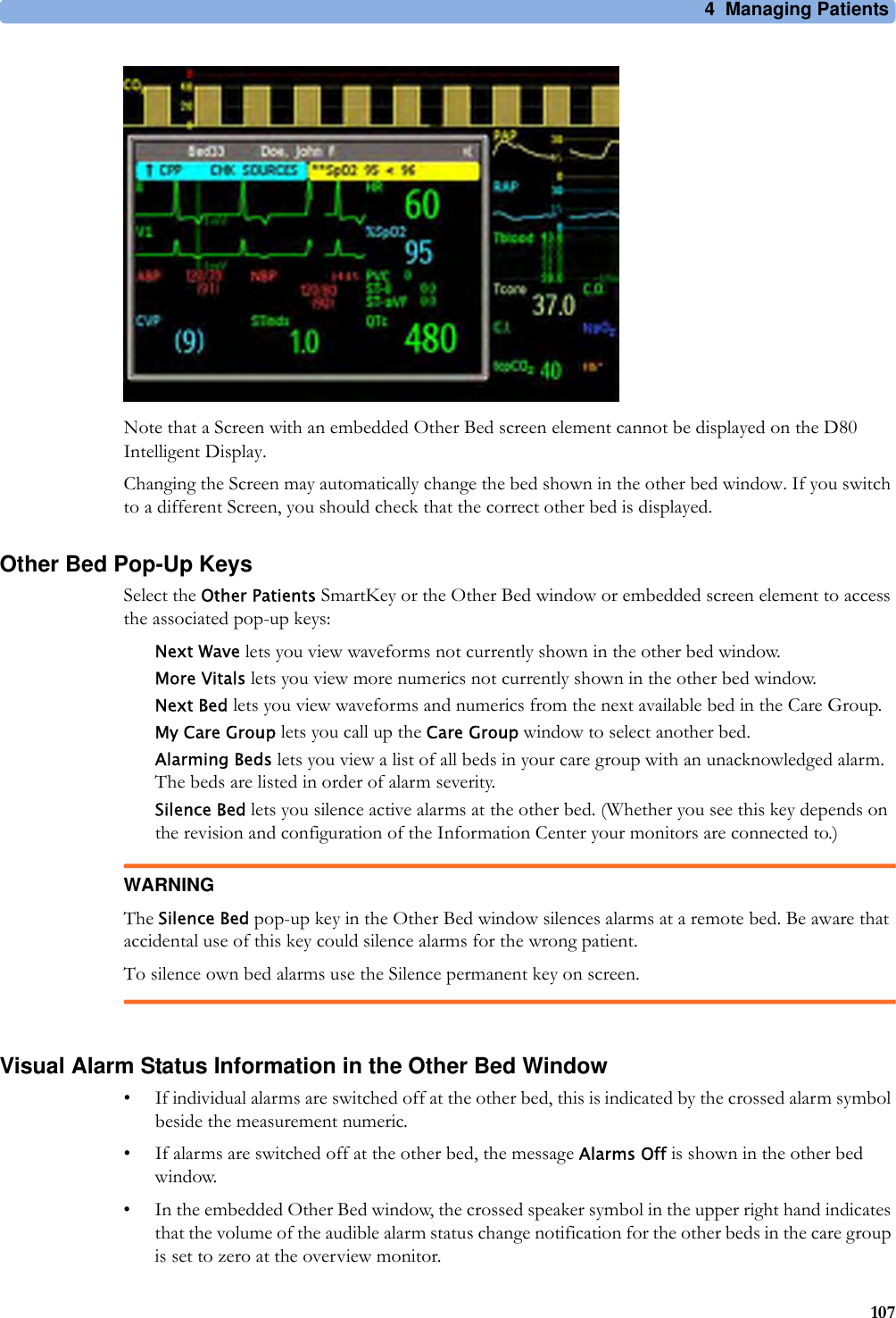
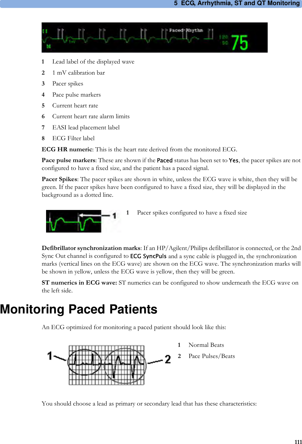
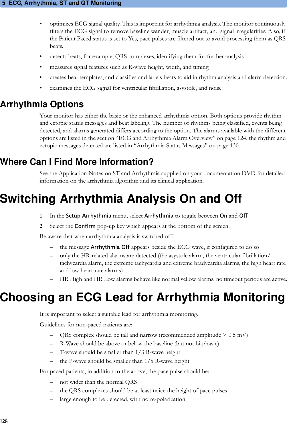
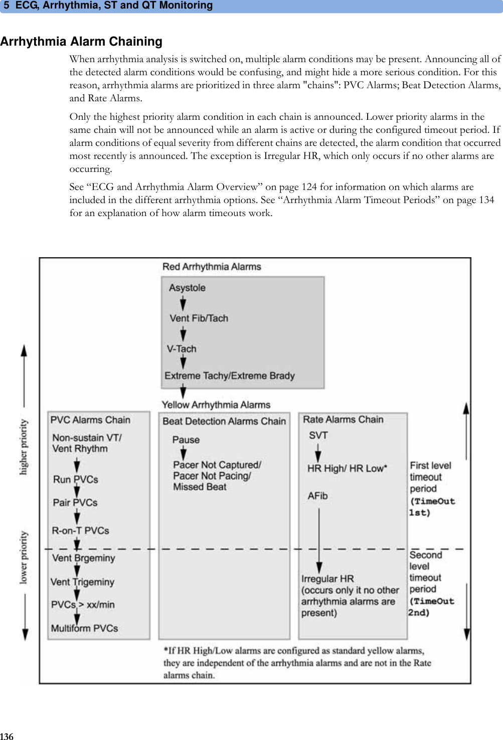
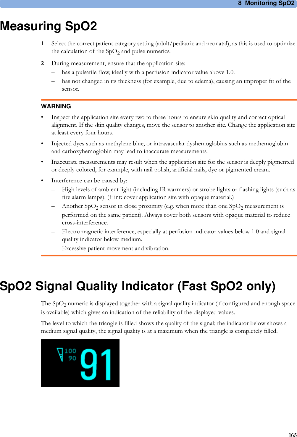
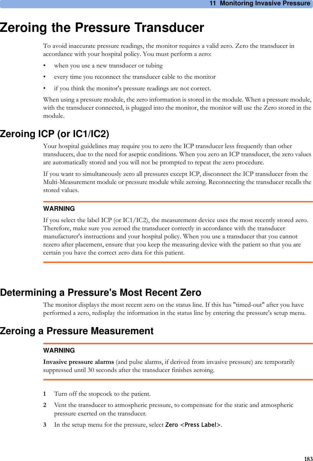
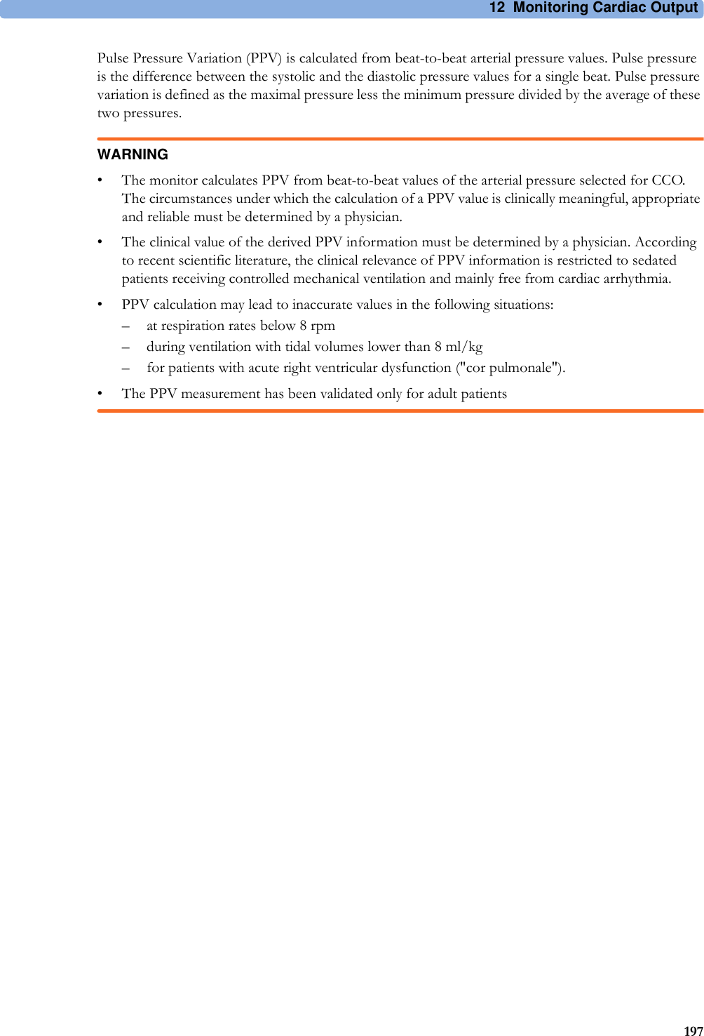
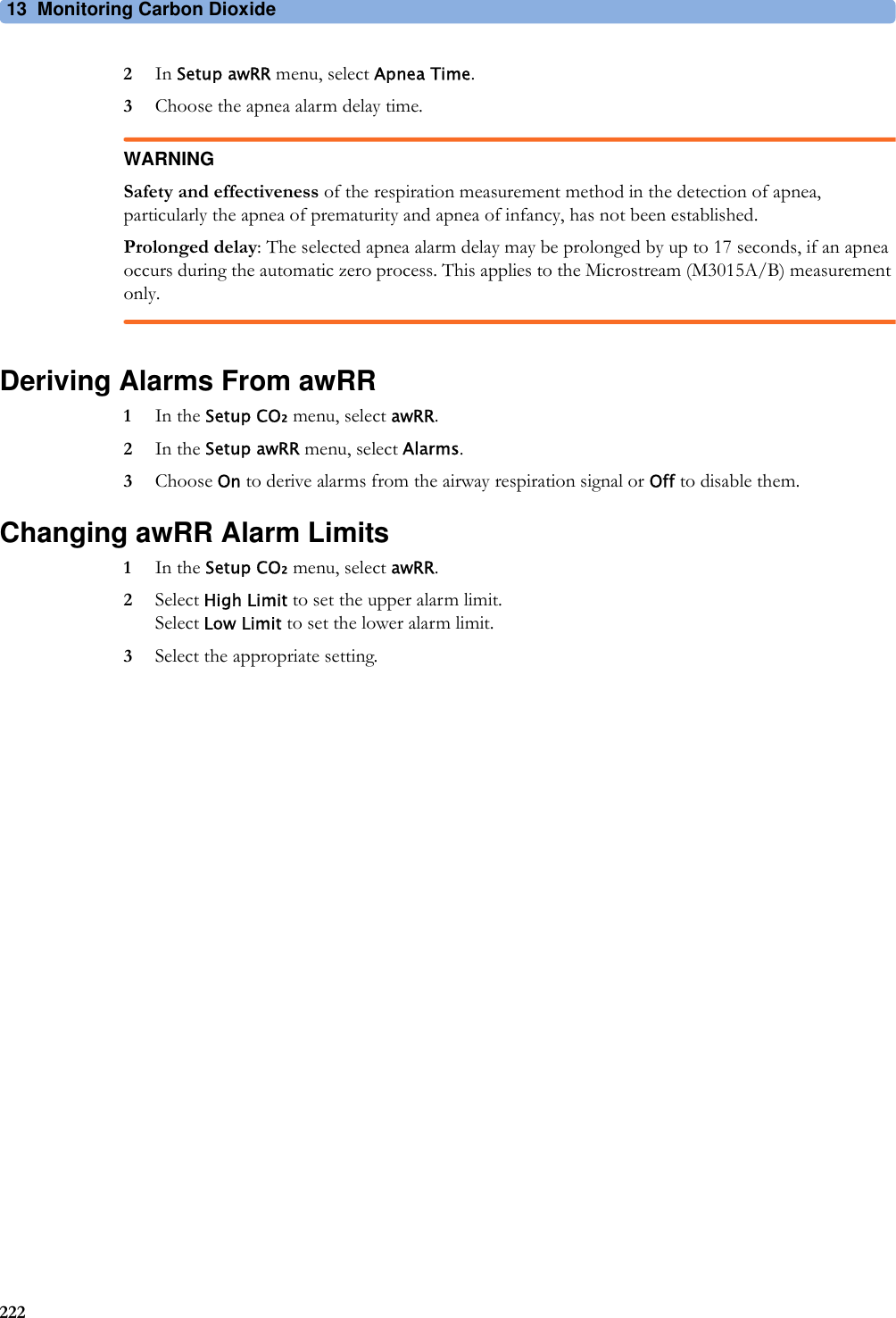
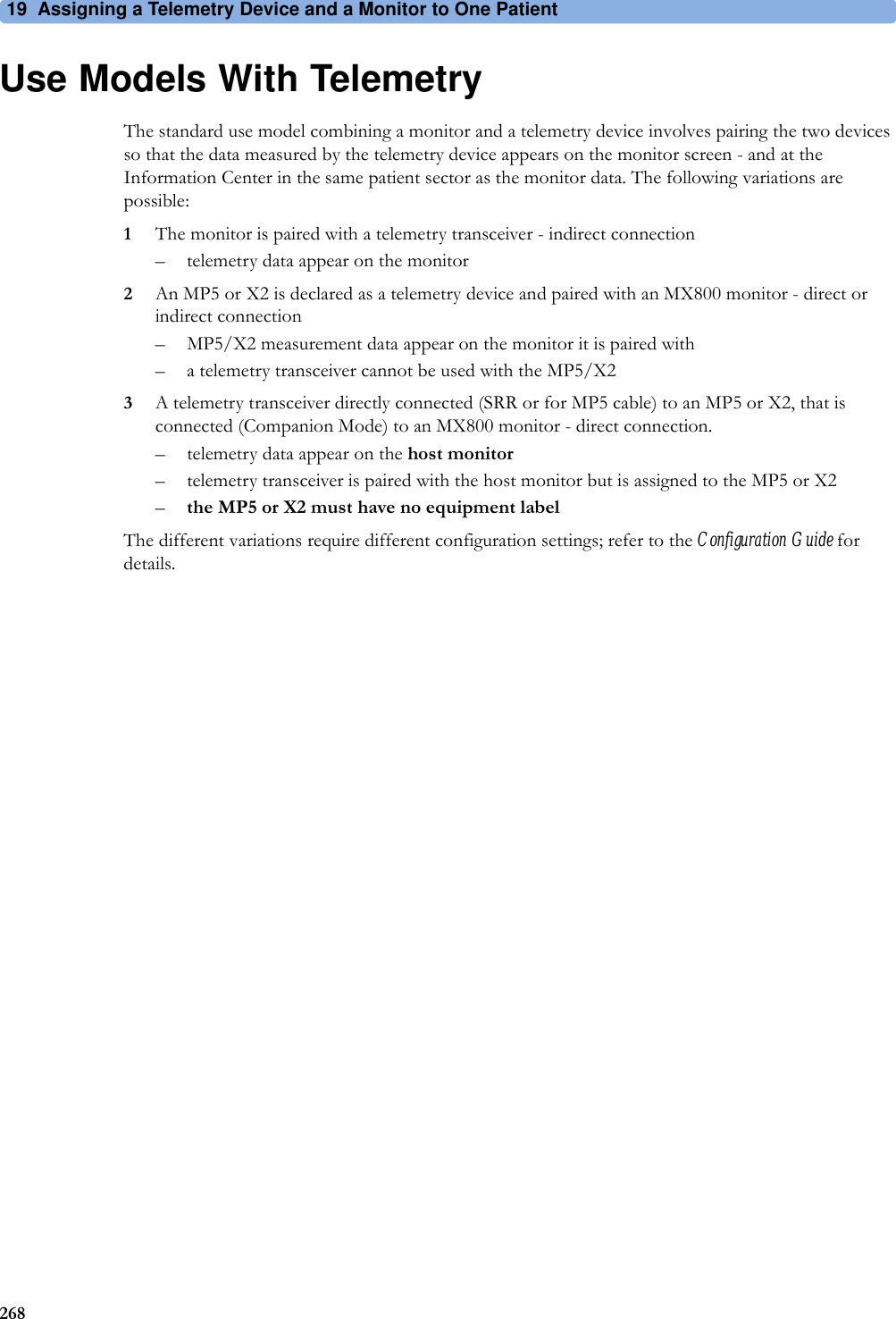
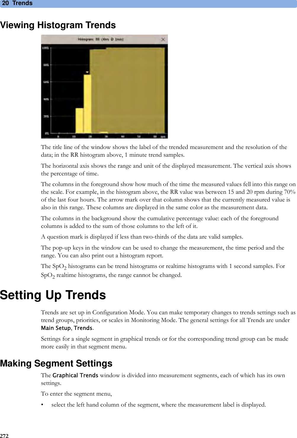
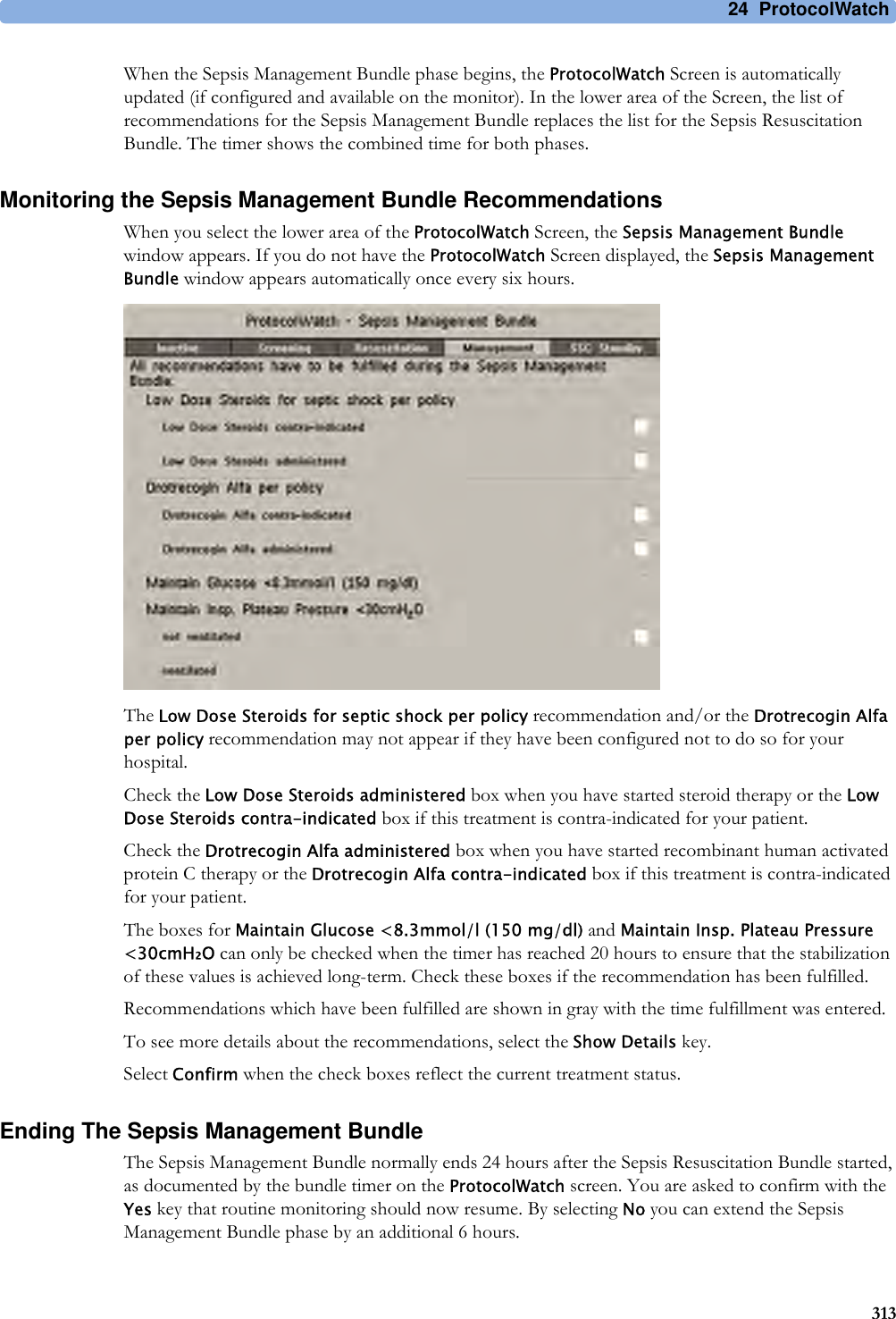
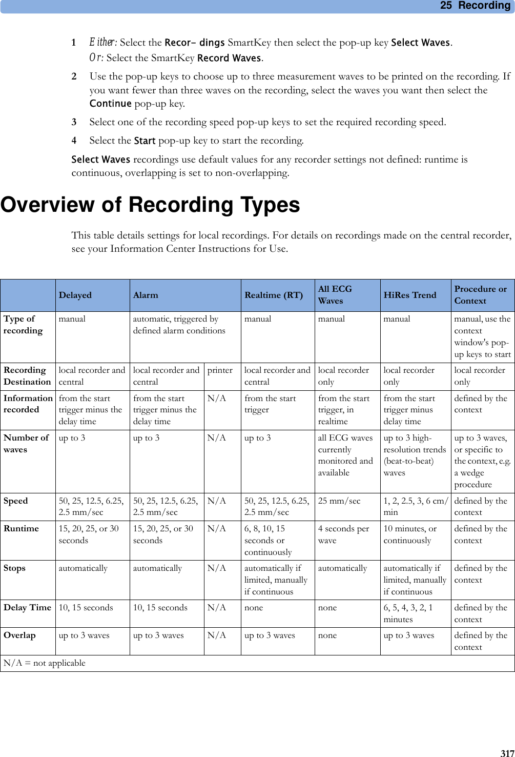
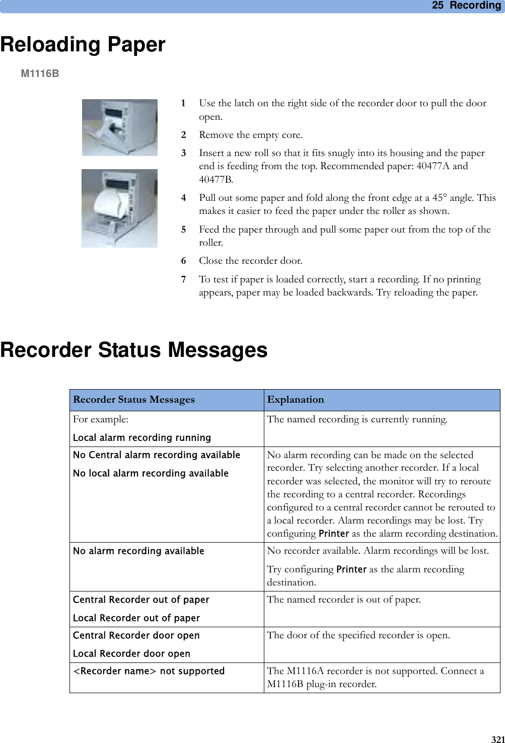
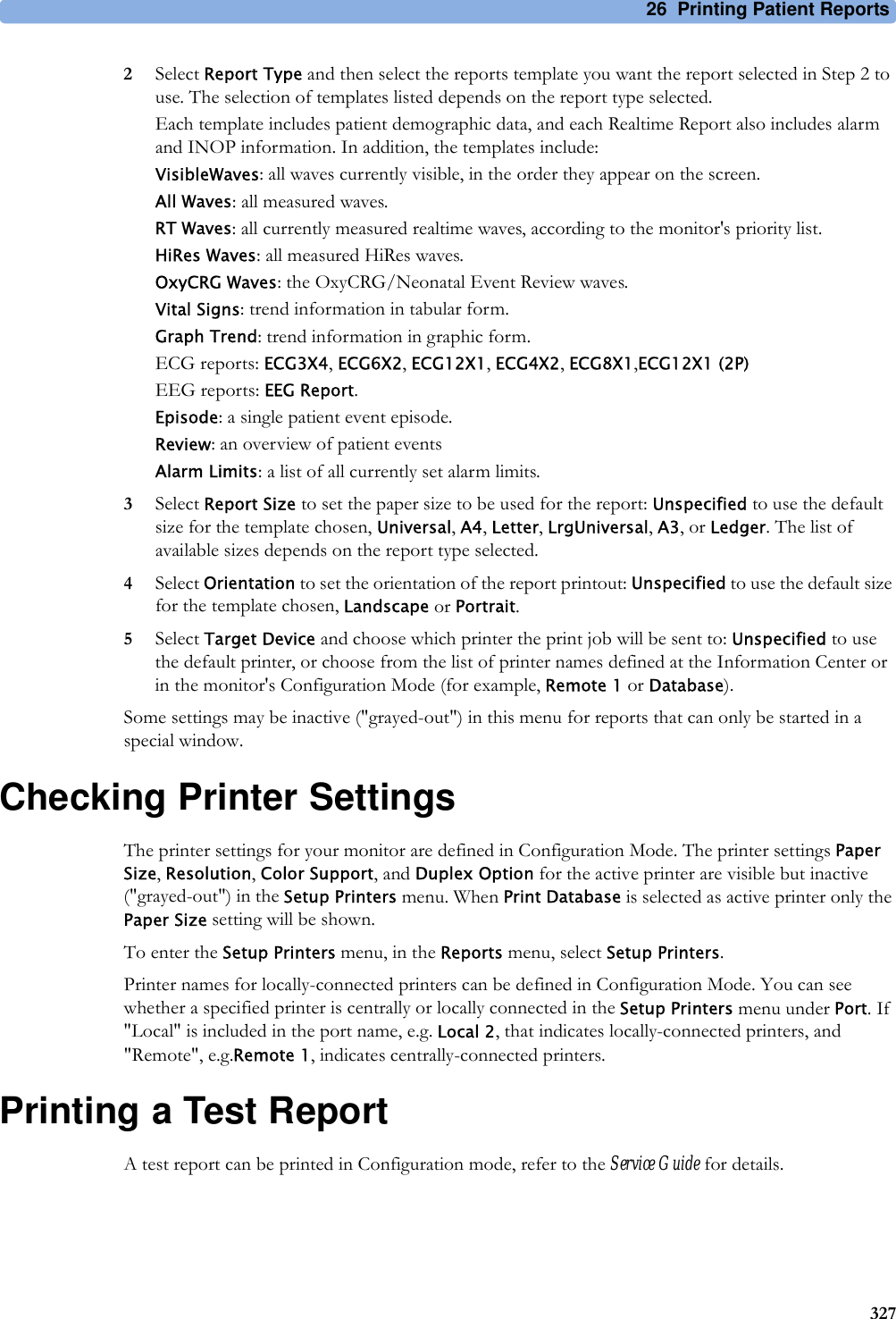
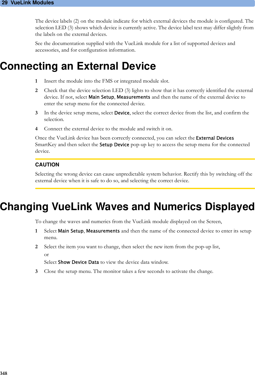
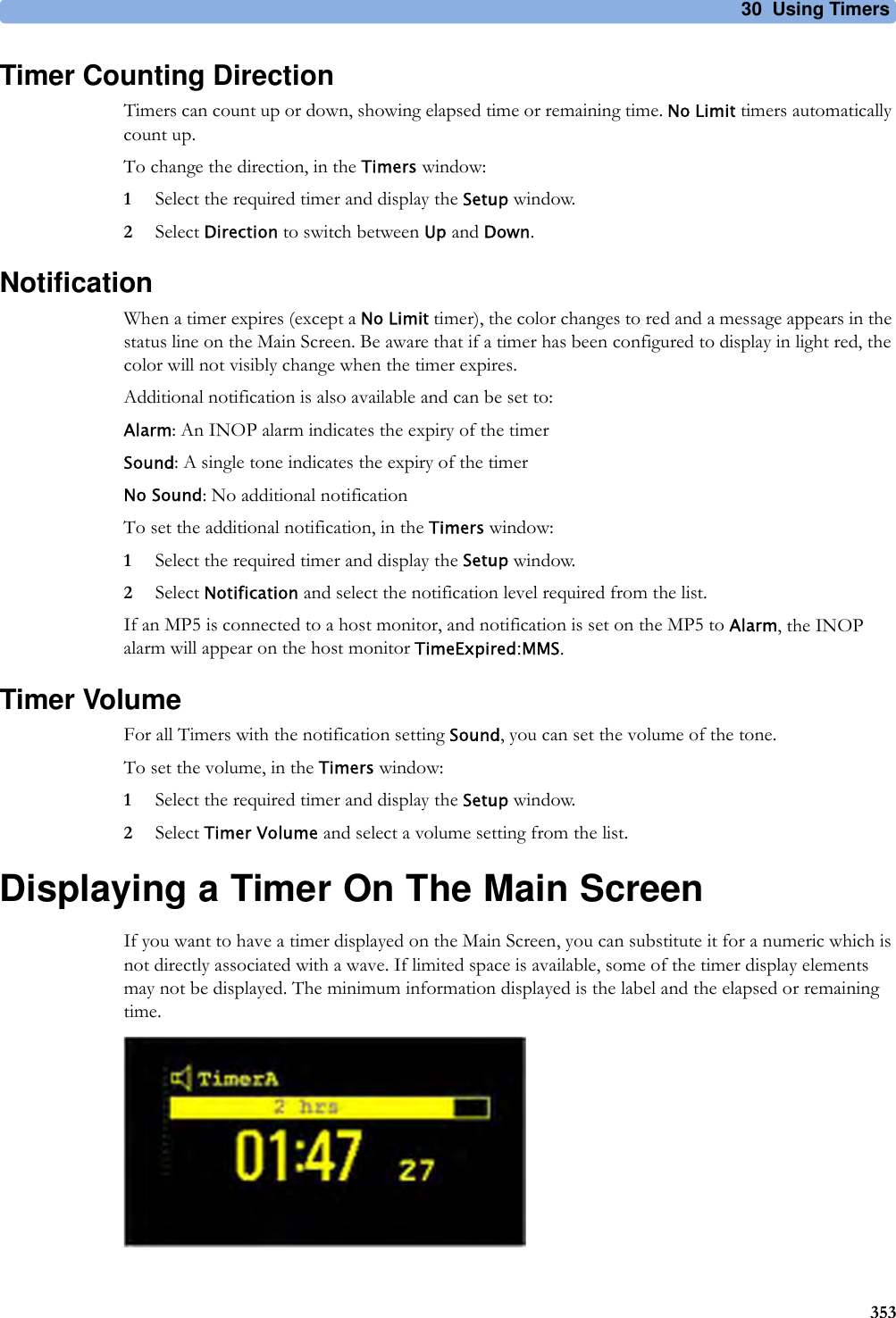
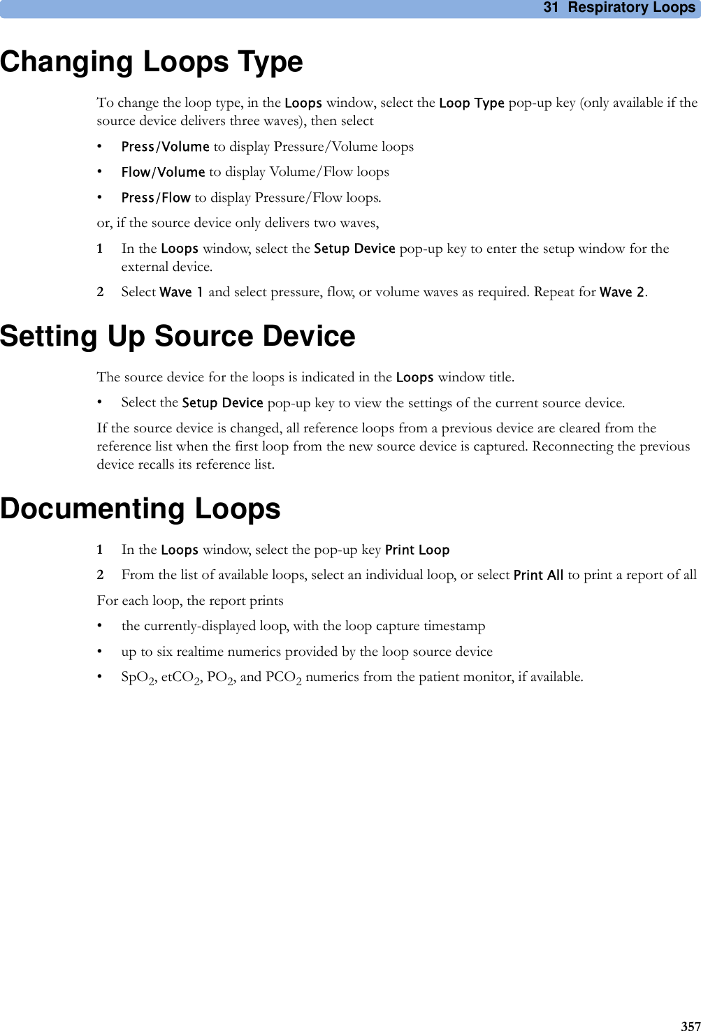
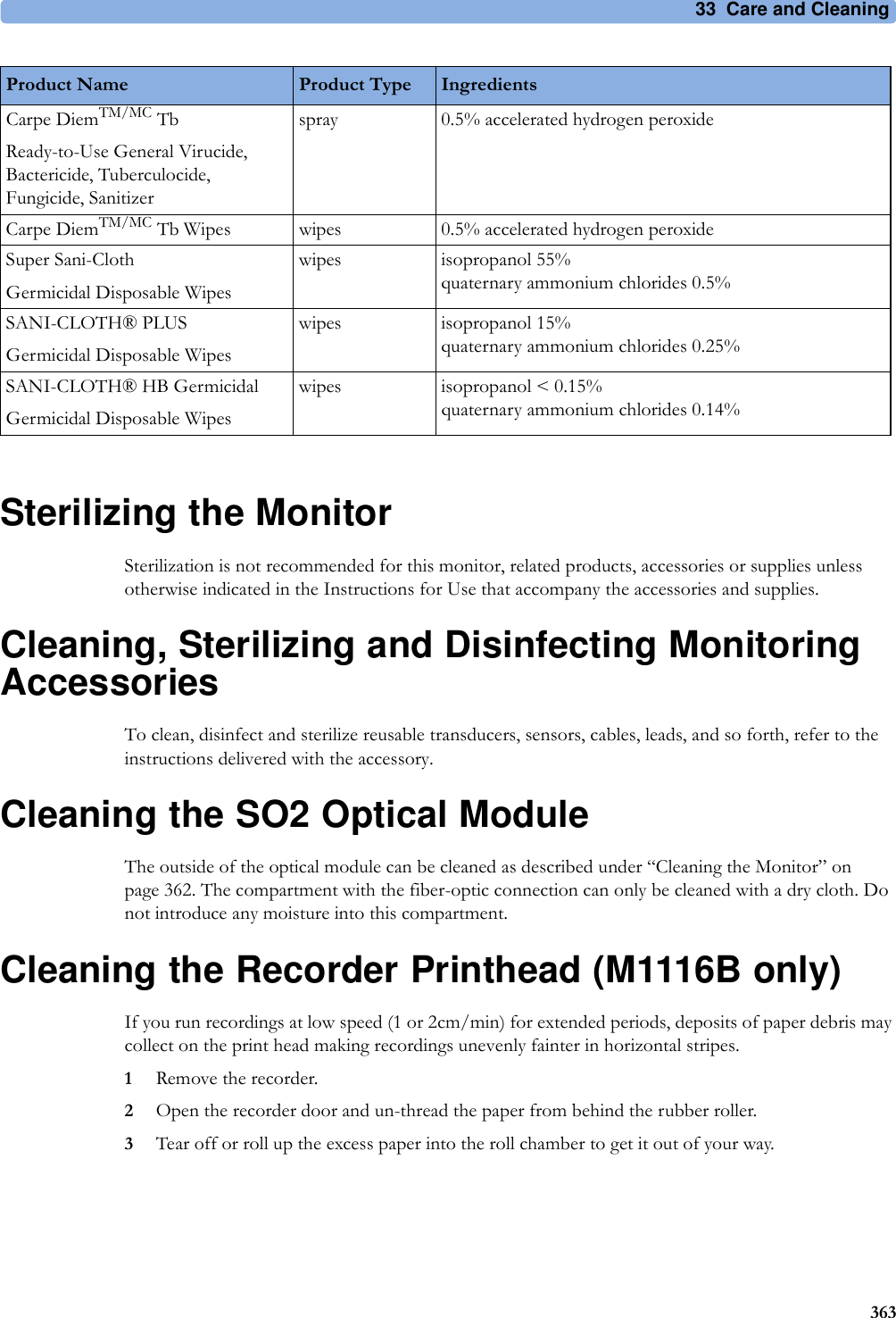
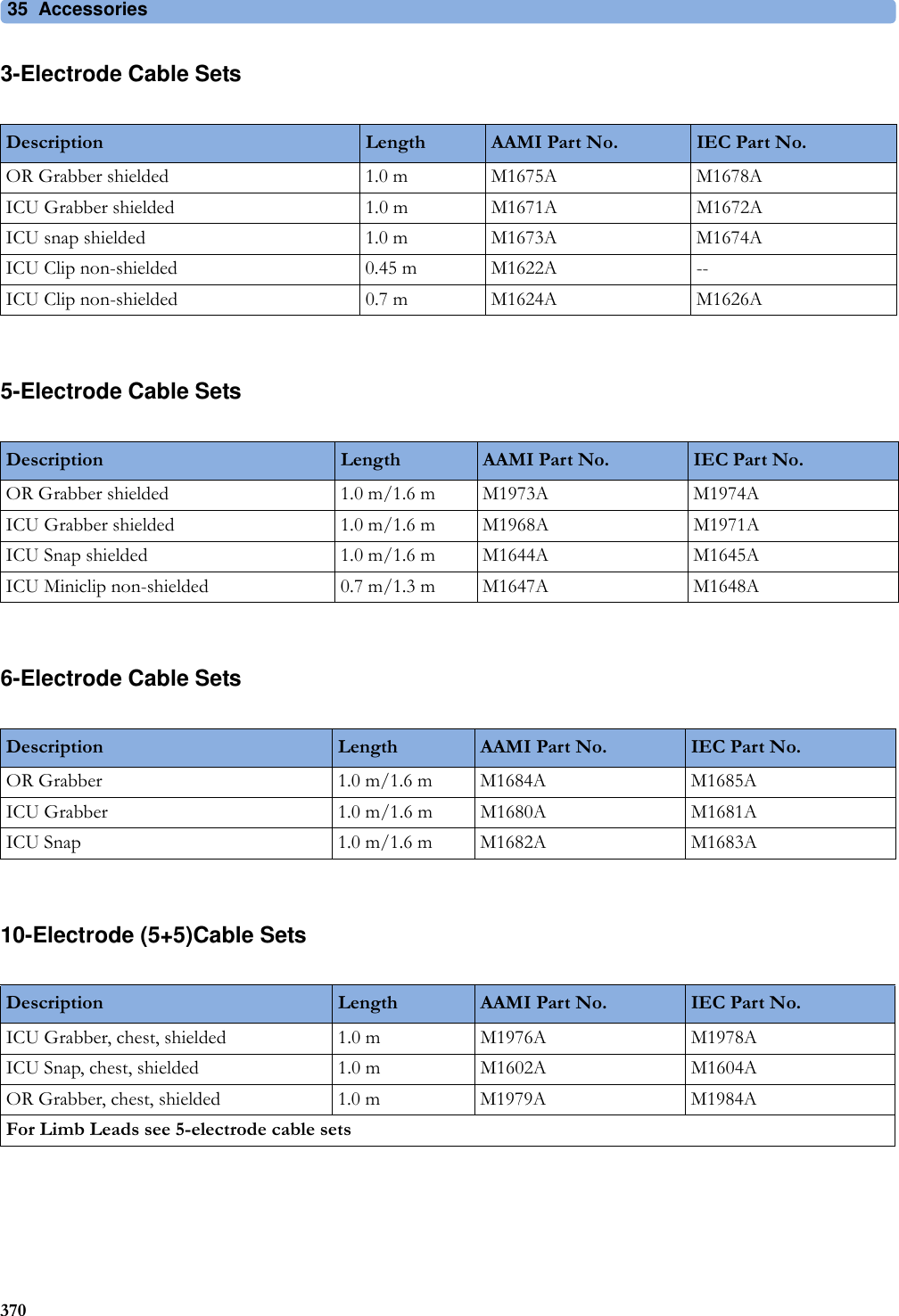
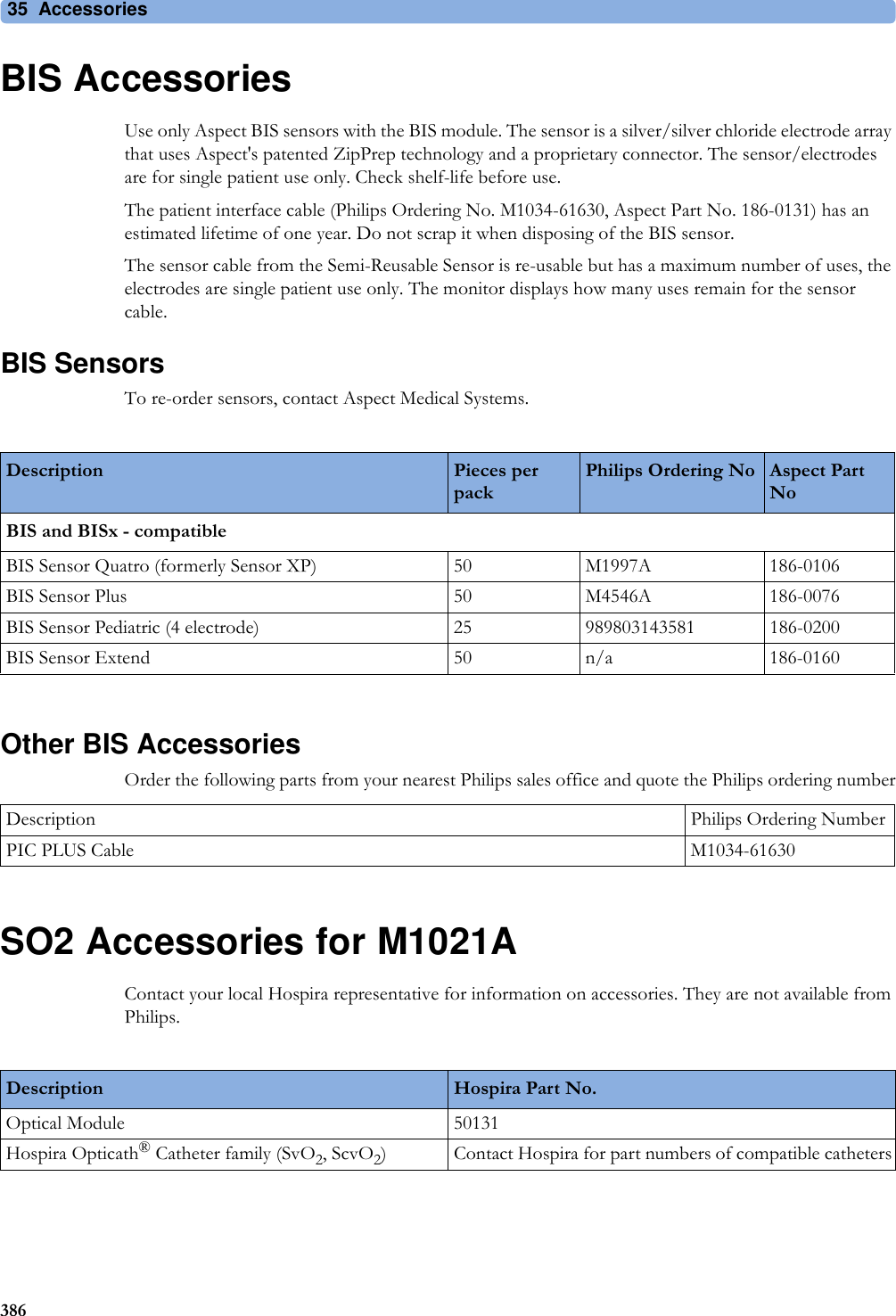
![3 Patient Alarms and INOPs85EEG INOPs<tcGas Label> EQUIP MALFNumeric is replaced by -?-INOP toneThere is a malfunction in the transducer or module. Connect another transducer. If this INOP persists, contact your service personnel.<tcGas Label> NO TRANSDUCNumeric is replaced by -?-INOP toneNo transducer is connected to the tcpO2/tcpCO2 module. Silencing the alarm switches off the measurement.<tcGas Label> STABILIZINGNumeric is replaced by ?The transducer has not yet reached the selected temperature and/or skin hyperemization is not yet finished. This INOP will disappear within three minutes.<tcGas Label> UNPLUGGEDNumeric is replaced by -?-INOP toneThe measurement is switched on but the module is unplugged.The measurement automatically disappears from the display. Silencing this INOP switches off the measurement.INOP Message, Indication What to do INOP Message, Indication What to do EEG EQUIP MALFINOP toneThe EEG hardware is faulty. Contact your service personnel.EEG IMPEDANCE HIGHEEG1 IMPED. HIGHEEG2 IMPED. HIGHThe signal electrode in one or both channels exceeds the user-selected impedance limit, or the impedance of a single electrode exceeds the limit. Check the impedance. If the impedance is too high, reconnect the electrodes according to the EEG monitoring setup guidelines. If the INOP persists, contact your service personnel.EEG LINE NOISEEEG1 LINE NOISEEEG2 LINE NOISEExcessive line noise has been detected in either channel EEG1 or EEG2, or in both EEG channels. Keep all cables together and away from metallic bodies, other cables & radiated fields.EEG MUSCLE NOISEEEG1MUSCLE NOISEEEG2MUSCLE NOISEToo much power above 30 Hz has been detected in channel EEG1 or EEG2, or both. Check the Electrode-to-Skin Impedance and reposition the electrode away from possible muscle activity, if necessary.EEG NO TRANSDUCINOP toneThe trunk cable is disconnected from the EEG plug-in module. Reconnect the trunk cable. Silencing this INOP switches the measurement off.EEG UNPLUGGEDINOP tonePlug in module. Silencing this INOP switches off the measurement.EEG1 LEAD OFF <n>EEG2 LEAD OFF <n>[n = electrode]Reconnect specified electrode.EEG1 LEAD OFFEEG2 LEAD OFFat Information CenterOne or more electrodes are not connected. Check in the EEG Impedance / Montage window on the monitor which electrode(s) are affected and reconnect the electrodes.EEG1 LEADS OFFEEG2 LEADS OFFTwo or more electrodes are not connected. Check in the EEG Impedance / Montage window which electrodes are affected and reconnect the electrodes.EEG1 OVERRANGEEEG2 OVERRANGEInput signal is too high in one or both channels. This is usually caused by interfering signals such as line noise or electrosurgery.](https://usermanual.wiki/Philips-Medical-Systems-North-America/SRRBV2.User-Manual-Olympus/User-Guide-1340937-Page-85.png)


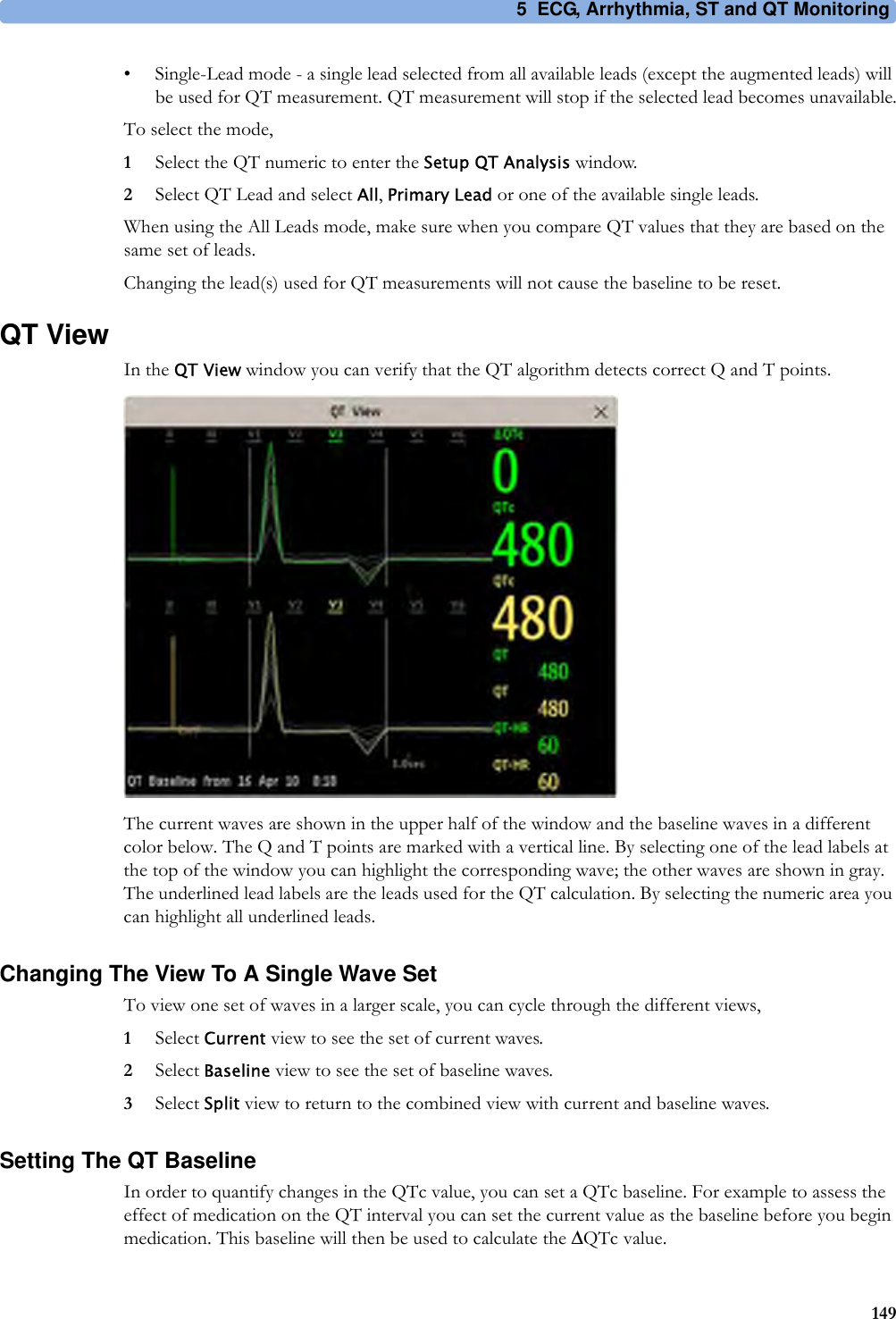


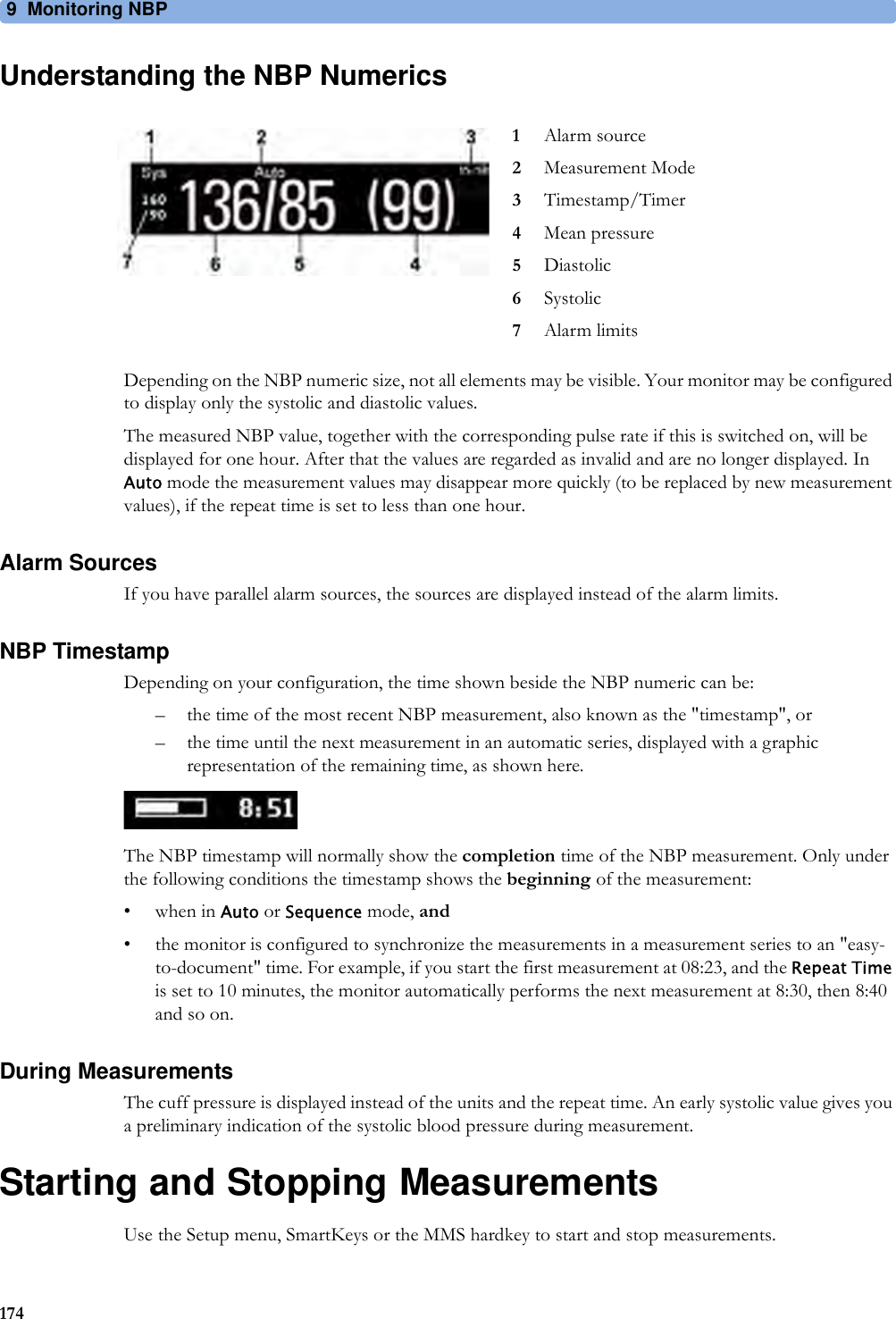


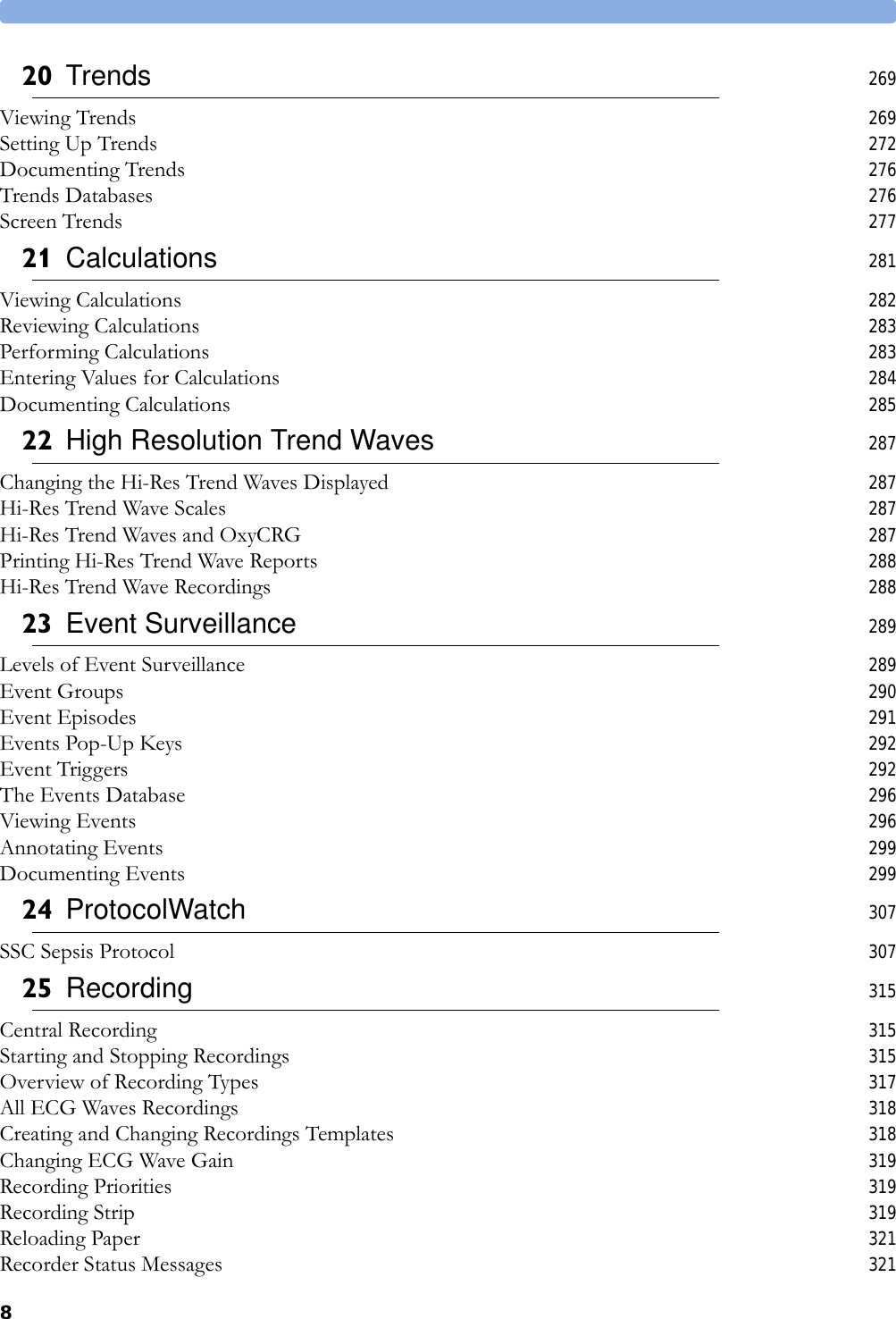
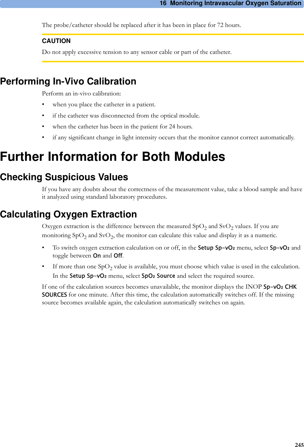
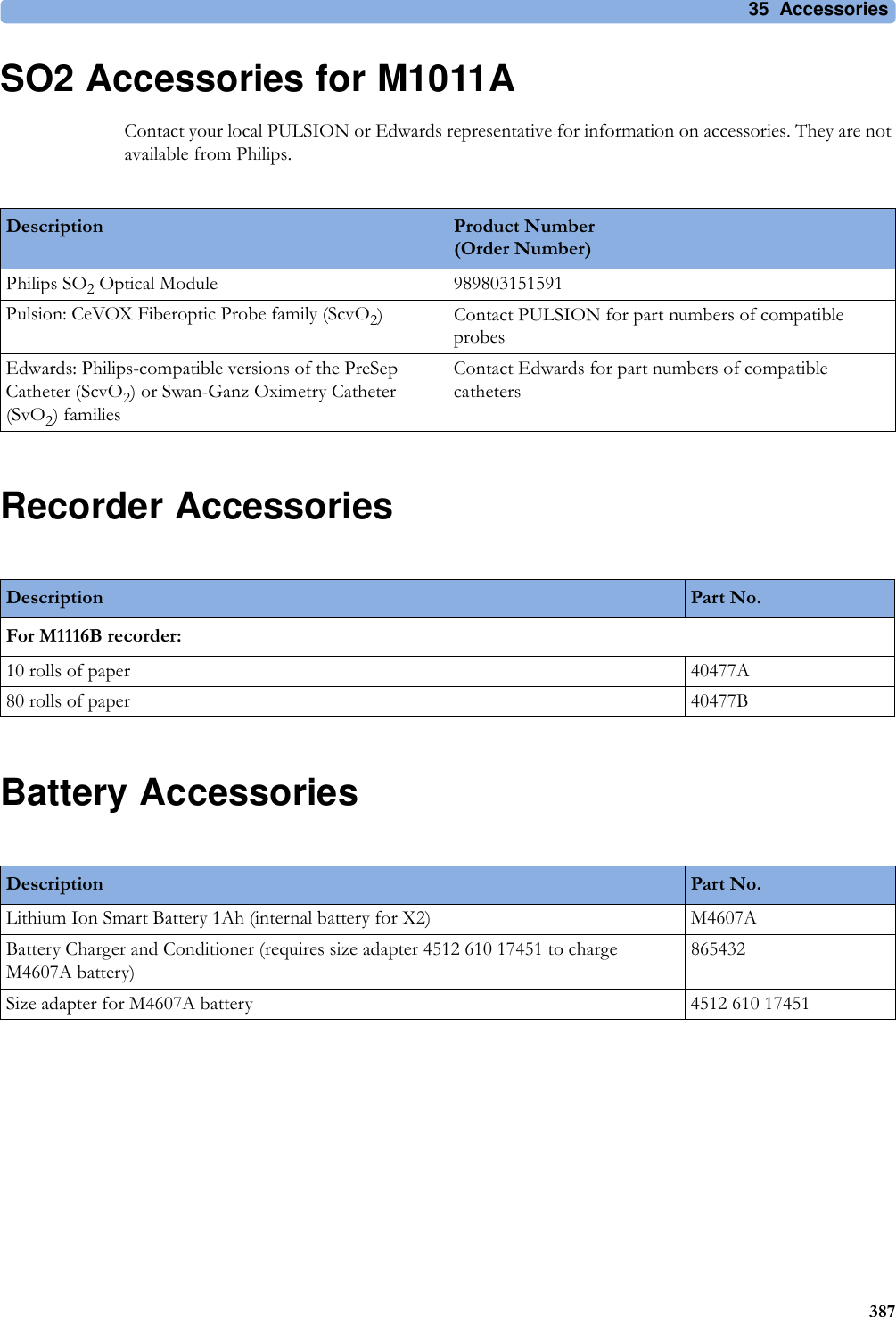
![16 Monitoring Intravascular Oxygen Saturation243Making the In-Vivo Calibration1Be prepared to draw a blood sample from the patient.2In the Setup <SO₂ Label> menu, select Start In-VivoCal.3To clear the distal lumen, draw off and discard at least 2 ml of blood before taking the sample.4Draw a blood sample from the distal port of the catheter and flush the line according to standard hospital practice.5Obtain laboratory analysis of the sample using direct measurements.6Select CalibrationValue and select from the list the value received from the lab.7Complete the calibration by selecting Store In-VivoCal (even if the stored calibration value did not change) and select Confirm. This updates the data stored in the optical module.Selecting Recall Last Cal recalls the previously stored calibration value.If the calibration fails, check that the light intensity indicator is indicating a stable medium to high level. Repeat the calibration.Setting Up the In-Vivo CalibrationCheck for:• proper positioning of the probe/catheter in the patient.• relatively stable oxygen saturation in patient.• that the light intensity indicator is indicating a stable medium to high level.Depending on the probe/catheter in use you may need to enter a catheter correction factor. This will be indicated in the table in the Accessories chapter or in the catheter documentation.1In the Setup <SO₂ Label> menu, select Catheter Factor.2Enter the correction factor.Making the In-Vivo Calibration1Be prepared to draw a blood sample from the patient.2In the Setup <SO₂ Label> menu, select Start In-VivoCal.3To clear the distal lumen, draw off and discard at least 2 ml of blood before taking the sample.4Draw a blood sample from the distal port of the catheter and flush the line according to standard hospital practice.5Obtain laboratory analysis of the sample using direct measurements.6Select CalibrationValue and select from the list the value received from the lab.7Select Hct [%] (or Hb [mmol/l] or Hb [g/dl] depending on the set up) and enter the corresponding value from the laboratory analysis.To change the setup for entering the Hb/Hct, see “Changing the Lab Value Required for Entry” on page 244 below.8Complete the calibration by selecting Store In-VivoCal (even if the stored calibration value did not change) and select Confirm. This updates the data stored in the optical module.Selecting Recall Last Cal recalls the previously stored calibration value.If the calibration fails, check that the light intensity indicator is indicating a stable medium to high level. Repeat the calibration.](https://usermanual.wiki/Philips-Medical-Systems-North-America/SRRBV2.User-Manual-Olympus/User-Guide-1340937-Page-243.png)
![16 Monitoring Intravascular Oxygen Saturation244Changing the Lab Value Required for EntryYou can change the lab value required to be entered: Hb [g/dl], Hb [mmol/l] or Hct [%].1In the Setup <SO₂ Label> menu, select Hb/Hct Entry.2Select your preferred lab value and unit.Preparing to Monitor with the M1011A Narrow ModuleIn addition to the module, you need a Philips SO2 Optical Module and a compatible fiber optic probe or catheter. Use only the accessories listed as applicable for the intended measurement location in the Accessories section.Connecting the Optical Module1Connect the optical module to the SO2 module. Allow the optical module to warm up before you insert the probe/catheter and perform a calibration.Although the warmup message disappears from the screen after one minute, it is preferable to let the optical module warm up for 10 minutes for best accuracy.2Position the optical module to avoid contact with liquids. Fluid entering the catheter-optical module connection will impair measurement performance.3Place the optical module on the catheter tray in the space provided and open the lid.4For instructions on the placement of fiber optic catheters/probes, refer to the documentation provided with the accessory.After InsertionThe SO2 probe/catheter is thin and flexible, treat it carefully. Avoid kinking, bending or grasping the probe/catheter with forceps or a hemostat. Damage to the fiber results in low intensity light and a sudden decrease in intensity readings. Refer to the documentation provided with the fibre-optic probe/catheter, paying special attention to any precautions, warnings or contraindications.Secure the optical module directly attached or in close proximity to the patient, to avoid placing excessive tension on the catheter, which would result in movement of the catheter tip from the optimal position in the patient.You must perform an in-vivo calibration once the probe/catheter is in place.](https://usermanual.wiki/Philips-Medical-Systems-North-America/SRRBV2.User-Manual-Olympus/User-Guide-1340937-Page-244.png)


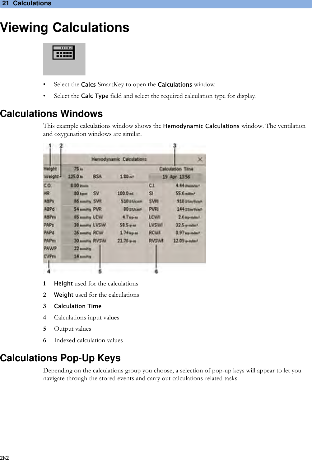
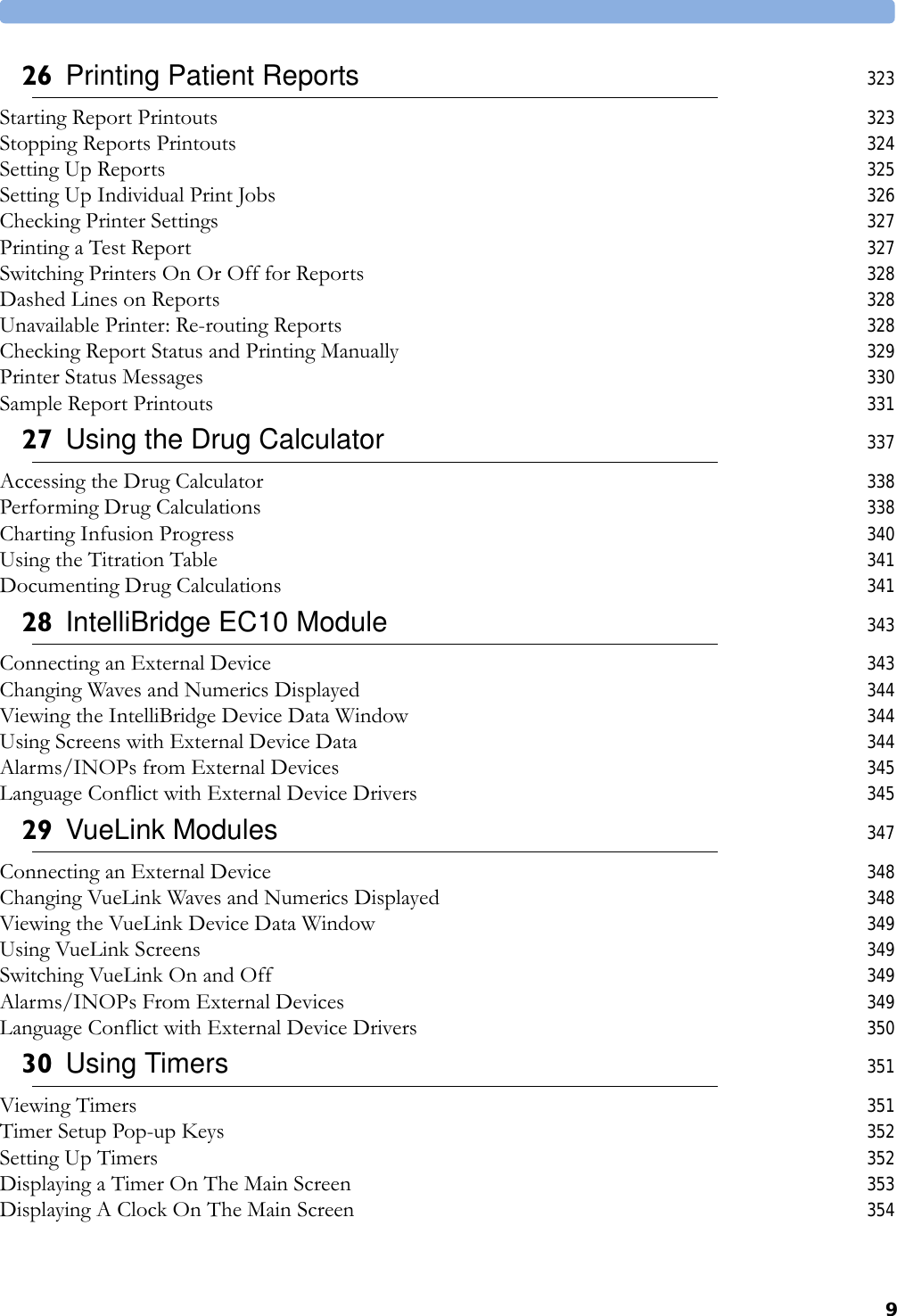
![21 Calculations2843Enter any values that must be entered or edited manually. Select the value field and then use the pop-up keypad to enter the required values. Select Enter to confirm each entered value. Manually-entered values are marked with an asterisk (*).Entering Values for CalculationsThe monitor automatically enters any available values for calculations. For aperiodically-measured values such as C.O., the monitor will re-use the most recent value in the calculation database until a new value becomes available. If the calculation time is the last C.O. time, values will be used from up to and including 30 minutes before the C.O. time, except for height and weight where the last available value will be used.• To enter calculations values manually or edit automatically-entered values, select the value field to open the on-screen keyboard and use this to enter the correct value. Values edited manually are marked with an asterisk (*).If you enter a value that has more decimal places than allowed for a particular input, the value you enter will be rounded off after you select Enter. If you enter a value which cannot be stored, the message Value out of range will appear. Enter a new value.In hemodynamic calculations, if the systolic and diastolic pressures are manually entered, the mean pressure is calculated and marked with an asterisk (*). The formula used to estimate the mean pressure is [systolic + (diastolic x 2)] / 3.Automatic Value SubstitutionIf the monitor cannot find a value required for calculation, it automatically tries to find an equivalent source for this value. For example, if C.O. is required but unavailable, the monitor automatically looks for CCO as a alternative source of C.O. values, or an alternative Pressure label may be used instead of ABP. The label of the value in the Calculations window does not change. Substituted values are marked with an asterisk (*).Automatic Unit ConversionThe monitor needs consistent units for performing calculations. It automatically converts units where necessary before it performs the calculation, for example, pressures sourced in kPa, cmH2O, or mbar are automatically converted to mmHg, or to cmH2O for ventilation calculations.Manual Unit ConversionIf you need to convert units for other purposes you can use the Unit Conversion window:1Select Main Setup then select Calculations.2Select Unit Conversion.3Select the field under the unit you know and use the on-screen keypad to enter the known value. The converted value automatically appears in the adjacent field.BSA FormulaYour monitor provides both the Boyd and Dubois formulas for the calculation of body surface area (BSA). For calculations, the monitor uses the setting defined in the Patient Demographics menu. All calculation results that use BSA are indexed to the selected formula.](https://usermanual.wiki/Philips-Medical-Systems-North-America/SRRBV2.User-Manual-Olympus/User-Guide-1340937-Page-284.png)


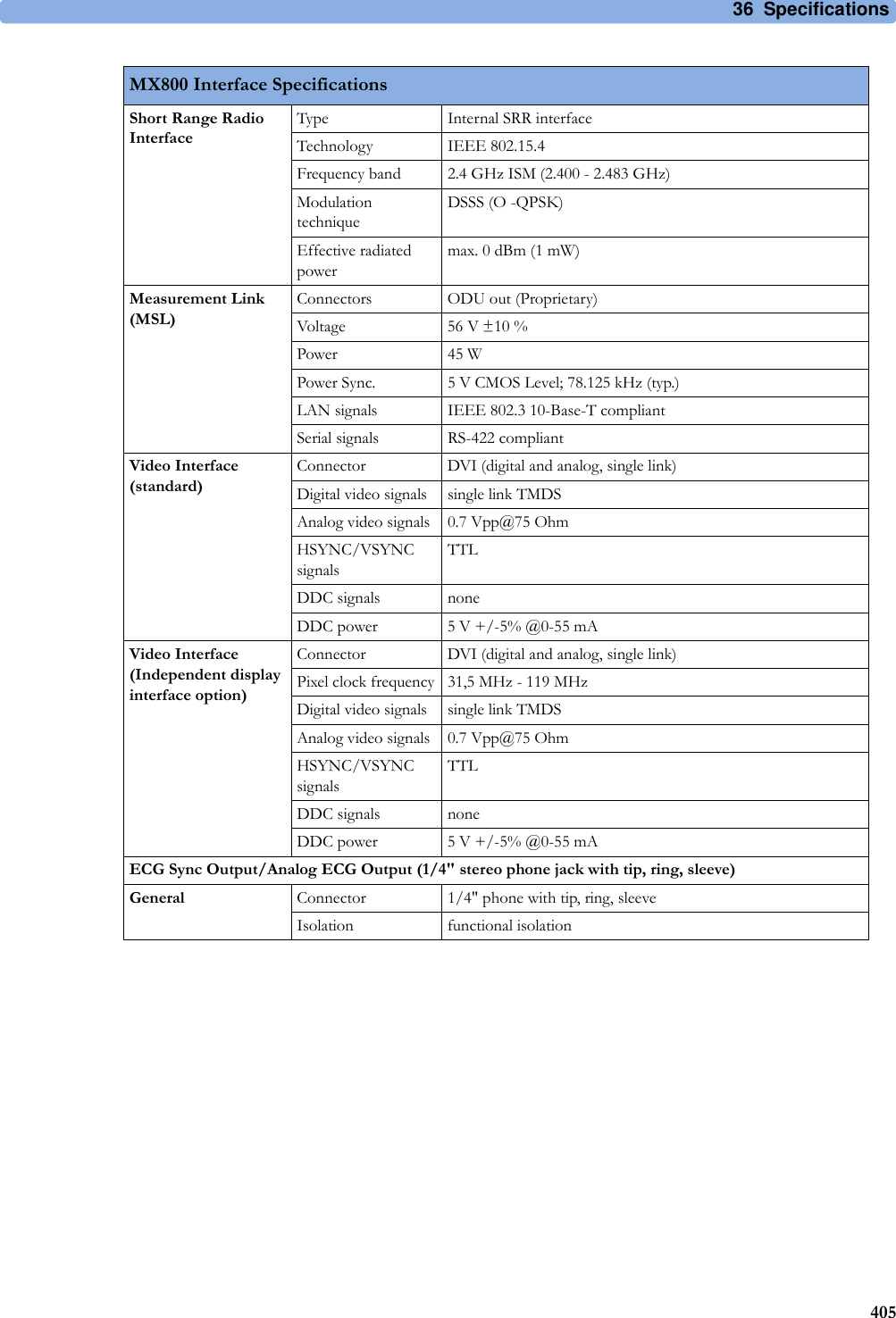
![36 Specifications404Interface SpecificationsMX800 Interface SpecificationsNetwork Standard 100-Base-TX (IEEE 802.3 Clause 25)Connector RJ45 (8 pin)Isolation basic insulation (reference voltage: 250 V; test voltage: 1500 V)MIB/RS232 Standard IEEE 1073-3.2-2000Connectors RJ45 (8 pin)Mode Software-controllableBCC (RxD/TxD cross over) orDCC (RxD/TxD straight through)Power 5 V ±5 %, 100 mA (max.)Isolation basic insulation (reference voltage: 250 V; test voltage: 1500 V)USB Interface (4 ports) Standard USB 2.0 full-speed (embedded host)Connector USB series "Standard A" receptaclePower Low power port 4.4V min; max. load for all ports together 500 mAIsolation noneRS232 (Standard) Connector RJ45 (8-pin)Power noneIsolation basic insulation (reference voltage: 250 V; test voltage: 1500 V)RS232 (Independent display interface option)Connector RJ45 (8-pin)Power noneIsolation noneBasic Nurse Call RelayConnector modular Jack 6P6C, active open and closed contactContact <=100 mA, <=24 V DCIsolation basic insulation (reference voltage: 250 V; test voltage: 1500 V)Delay <[Configured Latency +0.5] secIntelliVue Instrument Telemetry Wireless Network (USA only)Type Internal WMTS AdapterTechnology compatible with Philips IntelliVue Telemetry System (ITS), cellular infrastructureFrequency Band WMTS, 1395-1400 MHz and 1427-1432 MHzIntelliVue Instrument Telemetry Wireless Network (except USA)Type Internal ISM AdapterTechnology compatible with Philips IntelliVue Telemetry System (ITS), cellular infrastructureFrequency Band 2.4 GHz ISMIntelliVue 802.11 Bedside Adapter (Wireless Network Adapter)Type Internal Wireless AdapterTechnology IEEE 802.11a/b/gFrequency Band 2.4 GHz and 5 GHz ISM Band](https://usermanual.wiki/Philips-Medical-Systems-North-America/SRRBV2.User-Manual-Olympus/User-Guide-1340937-Page-404.png)
![36 Specifications406Analog ECG Output(ring, tip)Full scale on display signal gain x measured ECG voltageGain error <15 %Baseline offset <100 mVBandwidth 1 to 100 HzOutput voltage swing ±4 V (min)Signal delay <22 msSignal delay with older versions of the M3001A MMS[identifiable with the serial number prefix DE227 or DE441 and option string #A01]<30 msPacemaker Pulse filtered and included in ECG output signalDigital Pulse Output(ring)Output low voltage level<0.4 V @ I=-1 mAOutput high voltage level>2.4 V @ I=1 mAPulse Width 100 ms±10 ms (active high)Pulse Rise Time <1 ms (from 0.4 V to 2.4 V)Signal delay < 25ms per AAMI EC13Signal delay with older versions of the M3001A MMS[identifiable with the serial number prefix DE227 or DE441 and option string #A01]< 35ms per AAMI EC13X2 (M3002A) Interface SpecificationsMeasurement Link (MSL)Connectors Female ODU (Proprietary)Power 30 V to 60 V inputPower Sync. RS-422 compliant input 78.125 kHz (typical)LAN signals IEEE 802.3 10-Base-T compliantSerial signals RS-422 compliantLocal signals Provided for connecting MMS extensionsMX800 Interface Specifications](https://usermanual.wiki/Philips-Medical-Systems-North-America/SRRBV2.User-Manual-Olympus/User-Guide-1340937-Page-406.png)
![36 Specifications410Vent Rhythm Run 3 to 99 PVCs/minute 1 PVCSVT HR 120 to 300 bpm 5 bpmSVT Run 3 to 99 SV beats 1 SV beatST High -19.8 to +20 mm 0.2 mmST Low -20 to +19.8 mm 0.2 mmQTc High 200 ms to 800 ms 10 ms stepsΔQTc High 30 ms to 200 ms 10 ms stepsECG/Arrhythmia/ST Supplemental Information as required by AAMI EC11/13, IEC 60601-2-27Respiration Excitation Waveform Sinusoidal signal, 260 μA, 40.5 kHzNoise Suppression RL drive gain 44 dB max., max. voltage 1.8 VrmsTime to Alarm for TachycardiaVent Tachycardia1mVpp,206 bpmGain 0.5, Range 6.5 to 8.4 seconds, Average 7.2 secondsGain 1.0 Range 6.1 to 6.9 seconds, Average 6.5 secondsGain 2.0, Range 5.9 to 6.7 seconds, Average 6.3 secondsVent Tachycardia2mVpp,195 bpmGain 0.5, Range 5.4 to 6.2 seconds, Average 5.8 secondsGain 1.0, Range 5.7 to 6.5 seconds, Average 6.1 secondsGain 2.0, Range 5.3 to 6.1 seconds, Average 5.7 secondsTall T-Wave Rejection Capability Exceeds ANSI/AAMI EC 13 Sect. 3.1.2.1(c) minimum recommended 1.2 mV T-Wave amplitudeHeart Rate Averaging Method Three different methods are used:Normally, heart rate is computed by averaging the 12 most recent RR intervals.For runs of PVCs, up to 8 RR intervals are averaged to compute the HR.If each of 3 consecutive RR intervals is greater than 1200 ms (that is, rate less than 50 bpm), then the 4 most recent RR intervals are aver\-aged to compute the HR.Response Time of Heart Rate Meter to Change in Heart RateHR change from 80 to 120 bpm:Range: [6.4 to 7.2 seconds] Average: 6.8 secondsHR change from 80 to 40 bpm:Range: [5.6 to 6.4 sec] Average: 6.0 secondsHeart Rate Meter Accuracy and Response to Irregular RhythmVentricular bigeminy: 80 bpmSlow alternating ventricular bigeminy: 60 bpmRapid alternating ventricular bigeminy: 120 bpmBidirectional systoles: 90 bpmAccuracy of Input Signal Reproduction Methods A and D were used to establish overall system error and frequency response.Pacemaker Pulse Rejection Performance Rejection of pacemaker pulses with amplitudes from ±2 mV to ±700 mV and widths from 0.1 ms to 2.0 ms (Method A)ECG/Arrhythmia/ST/QT Alarm Specifications Range Adjustment](https://usermanual.wiki/Philips-Medical-Systems-North-America/SRRBV2.User-Manual-Olympus/User-Guide-1340937-Page-410.png)

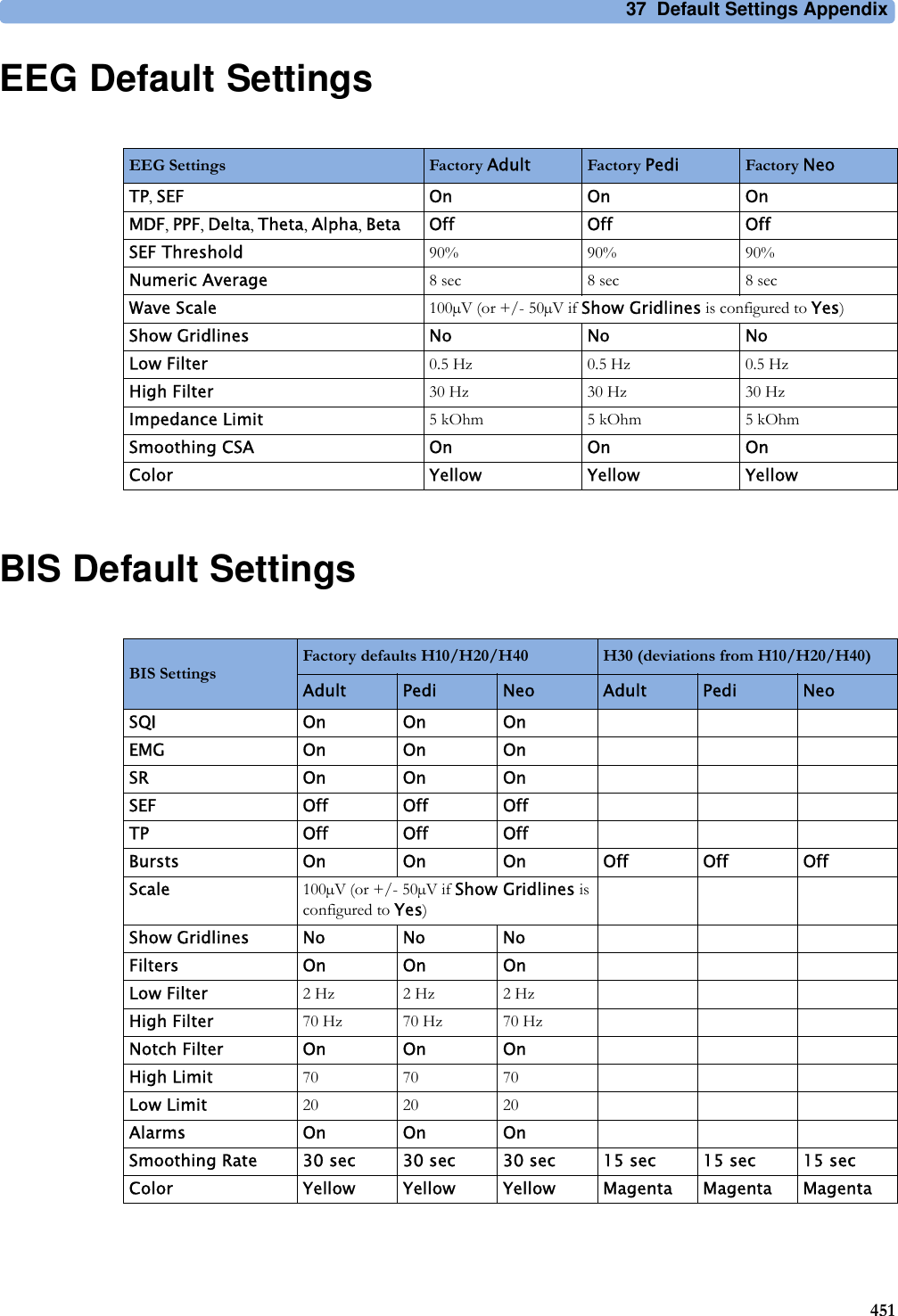
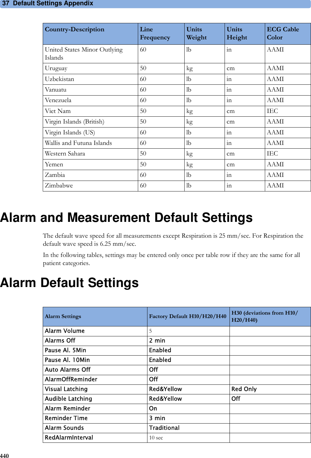
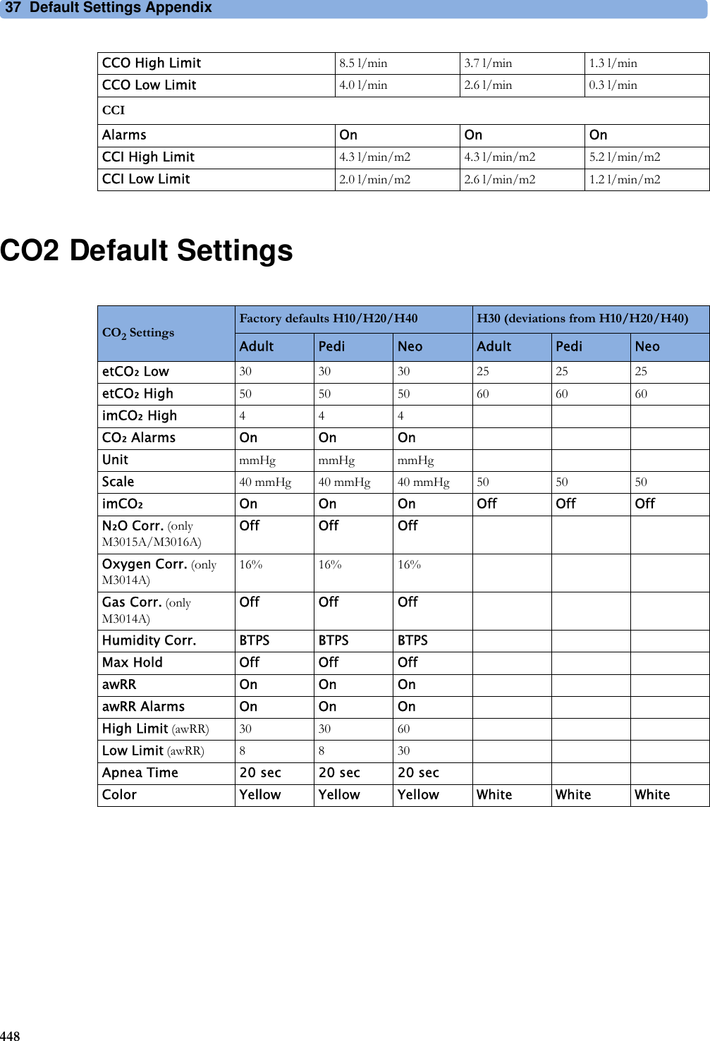
![3743337Default Settings AppendixThis appendix documents the most important default settings of your monitor as it is delivered from the factory. For a comprehensive list and explanation of default settings, see the Configuration Guide supplied with your monitor. The monitor's default settings can be permanently changed in Configuration Mode.Note: If your monitor has been ordered pre-configured to your requirements, the settings at delivery will be different from those listed here.Country-Specific Default SettingsCertain default settings are specific to a particular country. These are listed here for all countries alphabetically.Country-Description Line FrequencyUnitsWeightUnitsHeightECG Cable Color50/60 [Hz] kg, lb in, cm IEC, AAMIAfghanistan 50 kg cm AAMIÅland Islands 50 kg cm IECAlbania 50 kg cm IECAlgeria 50 kg cm IECAmerican Samoa 60 lb in AAMIAndorra 60 lb in AAMIAngola 50 kg cm IECAnguilla 60 lb in AAMIAntarctica 60 lb in AAMIAntigua and Barbuda 50 kg cm AAMIArgentina 50 kg cm AAMIArmenia 50 kg cm IECAruba 60 kg cm AAMIAustralia 50 kg cm AAMIAustria 50 kg cm IECAzerbaijan 50 kg cm IEC](https://usermanual.wiki/Philips-Medical-Systems-North-America/SRRBV2.User-Manual-Olympus/User-Guide-1340937-Page-433.png)


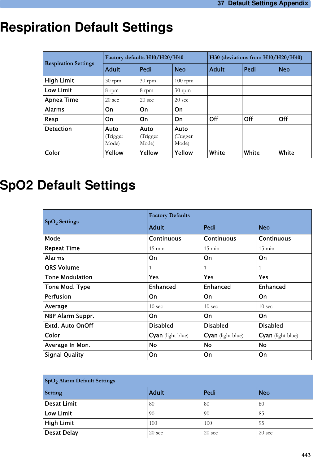
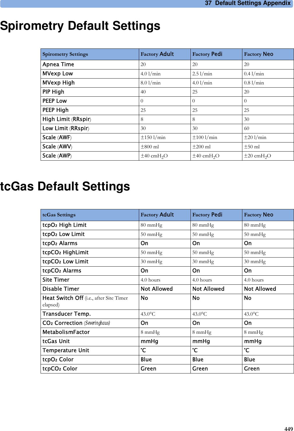
![37 Default Settings Appendix450SO2 Default SettingsSvO2 Default SettingsScvO2 Default SettingsSO2 Settings Factory Adult Factory Neo Factory PediLow Limit 70% 70% 70%HR High Limit 80% 80% 80%Alarms On On OnLight Intensity On On OnColor Yellow Yellow YellowHb/Hct Entry Hct [%]Factor Entry DisabledSO2 Settings Factory Adult Factory Pedi Factory NeoLow Limit 60% 60% 60%High Limit 80% 80% 80%Alarms On On OnLight Intensity On On OnColor Yellow Yellow YellowHb/Hct Entry Hct [%]Factor Entry DisabledSO2 Settings Factory Adult Factory Pedi Factory NeoLow Limit 70% 70% 70%High Limit 80% 80% 80%Alarms On On OnLight Intensity On On OnColor Yellow Yellow Yellow](https://usermanual.wiki/Philips-Medical-Systems-North-America/SRRBV2.User-Manual-Olympus/User-Guide-1340937-Page-450.png)