SEA COM SEA157S VHF Marine Radiotelephone/Class A DSC GMDSS User Manual April 5 2000 FIRST DRAFT

SEA COM CORPORATION VHF Marine Radiotelephone/Class A DSC GMDSS April 5 2000 FIRST DRAFT

Maintenance/Service manual
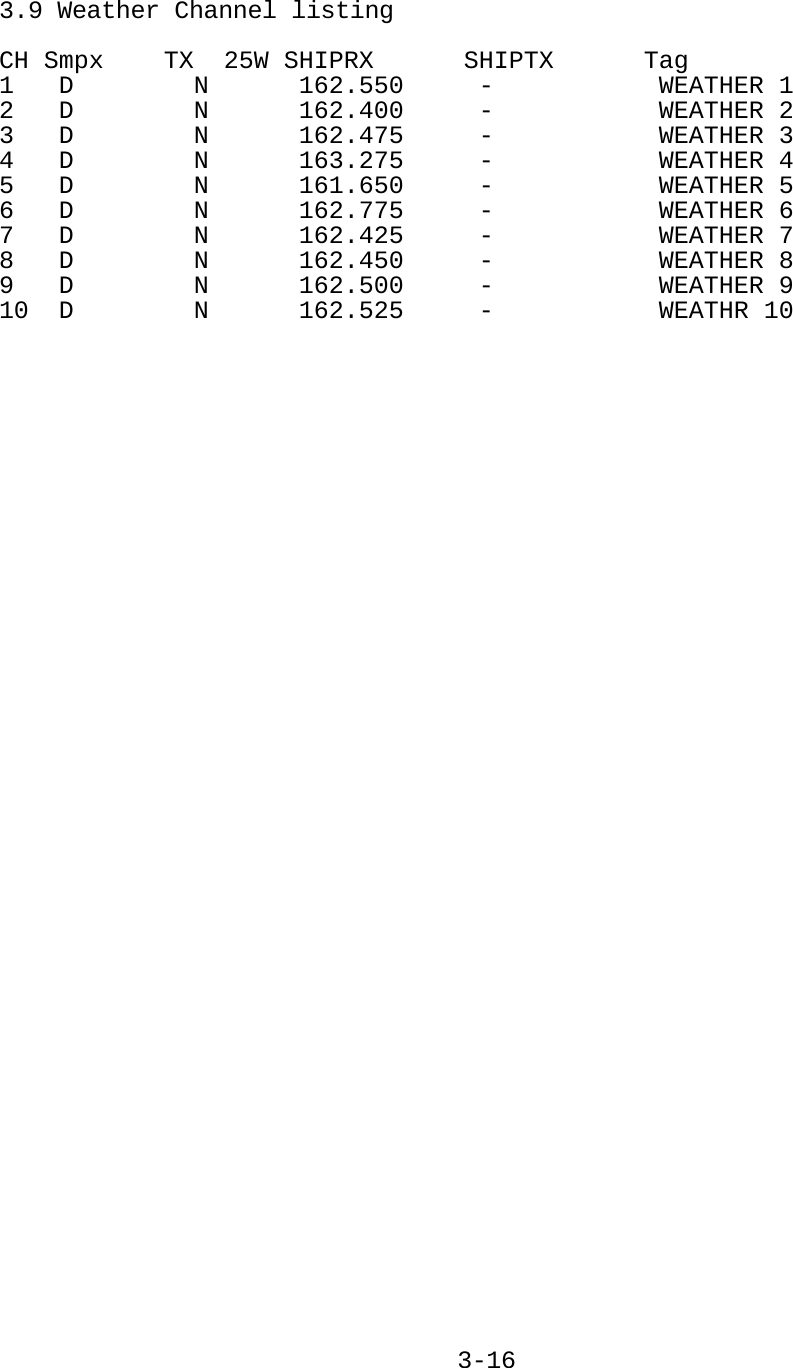
        SEA COM CORPORATION.    PRELIMINARY MAINTENANCE MANUAL       VHF FM RADIOTELEPHONE & DSC CONTROLLER    MODEL SEA 157S       © Copyright 2010    SEA COM Corp.    All rights reserved.       SEA COM Corp.   7030 220th St. SW   Mountlake Terrace, Washington 98043    TEL:   (425) 771-2182   FAX: (425) 771-2650              101 019A
    **IMPORTANT**    NOTICE TO INSTALLERS     ------------------------------------------------------------------  NOTE:  The safe compass distance for this equipment (As defined in     Paragraph 29 of IEC Publication 92-101, Third Edition):      SEA 157S VHF FM TRANSCEIVER/DSC CONTROLLER = 2.0 meters  ------------------------------------------------------------------
   TABLE OF CONTENTS              PAGE 1. INTRODUCTION............................................1-1  2.  SEA 157S SPECIFICATIONS.................................2-1  2.1 General............................................2-1  2.2 Transmitter........................................2-1  2.3 Receiver...........................................2-2  2.4 Mechanical.........................................2-2   2.5  DSC controller.....................................2-3   3.  OPERATING THE SEA 157S..................................3-1   3.1  Front Panel Controls...............................3-1  3.2 Display............................................3-1   3.3  Push To Talk.......................................3-1   3.4  Radiotelephone Operating System Functions..........3-2   3.5  Digital Selective Calling Operating System.........3-7   3.6  Using Test, Calibration and Diagnostic Utilities...3-13   3.7  USA Frequency List.................................3-14   3.8  International Channel list.........................3-15   3.9  Weather Channel list...............................3-16  4. INSTALLATION............................................4-1  4.1 Preliminary Check..................................4-1   4.2  Shelf or Overhead Mounting.........................4-1  4.3 Bulkhead Mounting..................................4-1   4.4  Power Supply Wiring................................4-1  4.5 Antenna Wiring.....................................4-1   4.6  External Speaker Wiring............................4-2   4-7  NMEA 0183 and RS232 Wiring.........................4-2  5.  THEORY OF OPERATION.....................................5-1  5.1 Frequency Synthesizer..............................5-1  5.2 Modulation Circuit.................................5-2  5.3 Main Receiver......................................5-2   5.4  Transmit Amplifier Chain...........................5-5   5.5  Antenna Interface Circuits.........................5-5   5.6  Automatic RF Power Control (APC) and TX Logic......5-6   5.7  TX Logic Detector..................................5-6   5.8  Power and Audio Circuits...........................5-6  5.9 Microcomputer Circuitry............................5-7  5.10 Keypad/Keypad Lighting.............................5-8 5.11 Display/Display Lighting...........................5-8  6. MAINTENANCE.............................................6-1  6.1 General............................................6-1   6.2  Recommended Test Equipment.........................6-1   6.3  Basic Performance Tests............................6-2  6.4 Transmitter Alignment..............................6-3  6.5 Receiver alignment.................................6-6   7. Block Diagram/Schematics............................7-1/7-9
    LIST OF FIGURES    FIG. ___________________DESCRIPTION___________________   Page   2.1    Front view of SEA 157S.............................2-4  2.2    Rear view of SEA 157S..............................2-5  4.1    Outline Dimensions of SEA 157S.....................4-3  4.2    Flush Mount Kit Drill Template for SEA 157S........4-4  6.1    Transmitter test setup.............................6-7  6.2    Receiver test setup................................6-8  7.1    Functional Block Diagram...........................7-1  7.2.1   RF Mainboard Schematic Diagram, Sheet 1............7-2  7.2.2   RF Mainboard Schematic Diagram, Sheet 2............7-2  7.2.3   RF Mainboard Schematic Diagram, Sheet 3............7-4  7.2.4   RF Mainboard Schematic Diagram, Sheet 4............7-5  7.2.5   RF Mainboard Schematic Diagram, Sheet 5............7-6  7.3    VCO Board Schematic Diagram........................7-7  7.4 Receiver Board Schematic Diagram...................7-7  7.5.1   CPU Mezzanine Board Schematic Diagram, Sheet 1.....7-8  7.5.2   DSP Mezzanine Board Schematic Diagram, Sheet 2.....7-8  7.6    Channel 70 Circuit Board Schematic Diagram.........7-9
 1 INTRODUCTION       This SEA 157S Service Manual provides detailed technical information for use by installation and service technicians.    General operating instructions and installation drill templates are provided in the SEA 157S Operator's Handbook (SEA P/N OPR-157S) supplied with each SEA 157S.    SEA COM Corp. continually strives to improve its products so that we may better serve our customers.  SEA COM reserves the right to make changes to SEA 157S specifications, hardware, software or documentation at any time without notice.    SEA COM's Marine Service Department is always available to provide additional help with technical difficulties.    Please call SEA COM's Service Department to obtain a Return Authorization Number (RA#) before shipping equipment to SEA COM.    Service parts are available through SEA COM Marine Sales/Service Departments.  Please order parts using SEA part numbers found in Section 8.                               1-1
2  SEA 157S SPECIFICATIONS:  2.1 GENERAL   FREQUENCY RANGE:   TX 155-159MHz        US TX 156.0-157.5MHz        RX 155-164MHz   FREQUENCY RESOLUTION:  12.5kHz   CHANNELS:     All US, Canadian, Int'l        plus 10 WX   POWER REQUIREMENT:   Voltage: 13.6Vdc, +/-15%        Negative Ground     CURRENT:     Max TX: 5.5 Amps (25W)          1.0 Amps (1W)        RX (STBY): 0.4 Amps        RX (Max): 1.0 Amps       FUSES:     7.5 Amps  (External)      2.2 TRANSMITTER   EMISSION:     16K0F3E & 11K2F3E (Voice)        13K5G2D (DSC)        11K2F2D (GMSK)    POWER OUTPUT:        25W, 1W into 50 ohms    SPURIOUS EMISSIONS:      -80 dB or better    SPURIOUS RADIATION:      Complies with FCC 80.211(f)    AUDIO HARMONIC DISTORTION:  10% max.    AUDIO FREQUENCY RESPONSE:   +1,-3dB of +6 dB/octave        Pre-emphasis 300-3000 Hz   HUM AND NOISE:    50 dB   FREQUENCY DEVIATION:   5kHz max. peak    CARRIER FREQUENCY STABILITY:  ±5ppm, -30 to +60 C    TRANSMITTER ATTACK TIME:    < 100 milliseconds       2-1
2.3 RECEIVER   FREQUENCY RANGE:   Simplex 155-159MHz        Semi-duplex 159-164MHz   INTERMEDIATE FREQUENCIES:  21.4MHz, 450kHz   SENSITIVITY:    <0.3uV for 12 dB SINAD    AUDIO FREQUENCY RESPONSE:   Within +1,-3 dB of 6 dB per         octave de-emphasis from 300-        3000Hz    AUDIO OUTPUT:        4W at less than 10%        distortion into external        4 ohm load.  2W internal   HUM AND NOISE:    Unsquelched: -45dB        Squelched:  -55dB    ADJACENT CHANNEL SELECTIVITY:  -80dB @ 25kHz        -85dB @ >50kHz    SPURIOUS EMISSION, RADIATION:  Complies with FCC    SQUELCH SENSITIVITY:   Threshold: .2uV max.        Tight:  max 10dB above        reference sensitivity    RECEIVER ATTACK TIME:    Less than 100mSec    RECEIVER CLOSING TIME:    100msec typical        250mSec max   SCAN RATE:     Max 10 channels/second    MODULATION ACCEPTANCE:    6kHz minimum          7kHz typical   2.4 MECHANICAL   DIMENSIONS:    (HEIGHT-WIDTH-DEPTH)        In: 3.6 x 9.6 x 3.1        mm: 91 x 244 x 79   WEIGHT:     Lbs: 3.0        Kgs: 1.4       2-2
2.5  SEA 157S VHF DIGITAL SELECTIVE CALLING CONTROLLER    The VHF Digital Selective Calling Controller incorporated into the SEA 157S VHF Radiotelephone has been designed to comply with all FCC regulations given in 47 CFR 80.225.  This encompasses compliance with the following documents, which are included for reference:    80.225(a)      ITU-R Recommendation M.493-9 Class D  80.225(a)   RTCM Paper 56-95/SC101-STD                                              2-3
Page 2-4 SEA 157S  Front View Figure 2.1
Page 2-5  Figure 2.2 SEA 157S  Rear View
3.  OPERATING THE SEA 157S  3.1  FRONT PANEL CONTROLS  Figure 2.1 illustrates the front panel of the SEA 157S.  The functions of the individual controls and indicators are listed below.  3.1.1  ROTARY CONTROL  The rotary control of the SEA 157S is used for several radio functions. It can be used to adjust the channel, volume, squelch and backlighting from the normal radio operating mode. In menu mode it is used to select from a list of menu options and is used to adjust the selected function.  The user can set the default mode for the rotary control using the setup menu. The rotary control will return to the default state 5 seconds (user selectable) after the last adjustment is made. Squelch mode adds 5 seconds to this timeout to allow for squelch on/off time while adjusting the level.  3.1.2  KEYPAD  A 15 key back-lighted keypad is provided which, together with the LCD graphics display, provides an operating system which permits the operator to control both the radiotelephone and digital selective calling (DSC) features of the SEA 157S.  3.1.3 PWR Key  Press and hold the PWR key for 3 seconds then release to turn the radio on. The display will light, indicating the radio is powered. To turn the radio off, press and hold the PWR key for 3 seconds then release. The display will turn off, indicating that the radio is powering down to the off condition.  3.2 DISPLAY  The SEA 157S uses a 128 X 64 graphics LCD display. The display is back-lighted and operates interactively with the keypad to provide an effective operator interface to the radiotelephone/DSC functions of the SEA 157S.  3.3  PUSH TO TALK  The radio is put into transmit mode by pressing the microphone push to talk key.  It remains in transmit mode until the push to talk switch is released or until an internal 5 minute timer expires.  A TX annunciator is displayed during transmit. Note: The internal DSC controller can also initiate transmissions independent of the push to talk switch on the microphone.    3-1
3.4  RADIOTELEPHONE OPERATING SYSTEM FUNCTIONS  3.4.1   CHANNEL SELECTION  The rotary control is used to select the channels. Push the ENT key until “Change Channel” is seen on the middle right side of the display, then use the rotary control to select the desired channel. This operates within the current channel list and wraps around at both ends of the list. eg. from channel 88A to channel 1 when moving up through the list.  The display shows the channel name below the channel number. The rotary control reverts to volume after 10 seconds of no activity.  The numerical keys can also be used to select a channel directly. The radio supports the standard 2 digit VHF channel list. To enter a channel press the channel number with leading zero digits to switch to the channel immediately. If a single digit is pressed and you delay for 10 seconds the radio will switch to that single digit channel. For example, to go to channel 23 press 2,3 to switch to the channel immediately. Press 0,5 to go to channel 5 immediately. Press 6 and pause for 10 seconds and the radio will switch to channel 6.  In the Weather list the operation is similar to this, if the 2 through 9 keys are pressed in WX mode the channel is selected immediately, because there are only 10 weather channels available. If 0 is pressed then the channel number from 1 to 9 is waited for with the first digit blinking. If 1 is pressed it waits for the 0 if you want to go to channel 10 or times out after 10 seconds and goes to channel 1.  3.4.2   VOLUME CONTROL  The rotary control is used for this function. The default mode is volume. Rotate the control to set the desired volume level. The display will show “Change VOL XX” on the middle right side, “XX” is the current volume level (0 to 15).  3.4.3   SQUELCH CONTROL  Push the ENT key until display shows “Change SQL XX” on the middle right side, “XX” is the current squelch setting (0 to 15), then use the rotary control to adjust the squelch level as desired. The squelch is returned to the user selected state 10 seconds after the last adjustment.  Pressing FUNC-9 will toggle the squelch on and off, as indicated by SQL in the upper right corner of the display.       3-2
3.4.4  ADJUSTING THE BACKLIGHTING LEVEL  Push the FUNC key until display shows “Change DIM XX” on middle right side of display. “XX” is the current brightness setting. 0 is off and 15 is maximum. Using the rotary control, adjust the brightness level as desired. The rotary control is returned to the user selected state 10 seconds after the last adjustment.  3.4.5   CHANNEL LIST SELECTION  Pressing FUNC-6 will toggle the radio between the USA, INT and WX channel lists. The radio will go to the last used channel in the selected list.   3.4.6   EMERGENCY CHANNEL SELECTION  Pushing the 16# key at any time, in any state of operation, will cause the radio to go to CH16 in the current frequency list, or in the case of pressing 16# key while in the Weather list, it will go to CH16 in the USA list.  3.4.7   TRANSMITTER POWER CONTROL  On channels that allow 25W transmission, pressing FUNC-7 toggles the transmitter power level between 25W and 1W. FUNC-7 is non-functional on channels that only allow 1W. When transmitting on a 1W only channel, the FUNC key may be held down while transmitting to temporarily switch to 25W. 1W will be displayed when in the 1W mode and 25W when in the 25W mode.  3.4.8   DUAL WATCH  The SEA 157S has two watch modes available. Dual watch is initiated by pressing FUNC-1 briefly while on the primary channel you want to monitor. DW will be indicated on the display and channel 16 will be checked every 2 seconds while there is no activity on either channel. If there is activity on the primary channel or on channel 16, the radio will remain on that channel until there is no activity for a pre-programmed number of seconds [hangtime]. This behavior can be changed so that channel 16 always has priority by using the Dual Watch setup menu option.  The display will indicate which channel is operational. Pressing PTT will exit dual watch and switch to the current channel.  Dual Watch will not be initiated if selected while on channel 16.   The Triple Watch function is started by pressing FUNC-1 for longer than 1 second on the primary channel that you want to monitor. TW will be indicated on the display and will check channel 16 and the Priority channel every 2 seconds. By default channel 16 has priority, but this behavior can be changed using the Triple Watch setup menu option.  3-3
3.4.9   SEEK  The Seek mode scans all channels in the selected list (USA/INT/WX) and is started by pressing FUNC-3. The display will show SCN and the radio will scan all the channels in the current list.  3.4.10   SCAN  The Scan function is initiated by briefly pressing the FUNC-2. The display will show SCN and the radio will scan the channels that are members of the Scan List (indicated by the MEM flag). The channels will be scanned and hold on an open channel for the user selectable hangtime after the channel becomes inactive. Channel 16 is always included in the scan list regardless of the MEM list state. Only the memorized channels in the current list will be scanned.  3.4.11  PRIORITY SCAN  If the priority channel is selected BEFORE entering the scan mode, the receiver scans the priority channel in between each channel.  3.4.12  SCAN CHANNEL PROGRAMMING  Press and hold the ENT key to bring up the Channel Operation menu. Select “Add to Scan List” function to tag current channel. If the selected channel is already in the list, menu selection reads “Del from Scan List”. Pressing the ENT key adds or removes the current channel from the scan list. The MEM flag will be on if the current channel is included in the scan list. The memorized channels can be scanned by using the MODE-2 scan function.  3.4.13  PRIORITY CHANNEL PROGRAMMING  Pressing FUNC-4 switches the radio to the programmed priority calling channel. Press and hold the ENT key to bring up the Channel Operation menu. Select “Make PRI Channel” to set the currently selected channel to the priority channel. The factory default for the PRI channel is channel 9, in the USA channel list.  The priority channel is also used by the Triple Watch mode and the Priority scan and seek modes.   3.4.14 CONFIGURATION MENU  The Configuration Menu contains general option selections and radio functions. Pressing FUNC-0 enters this menu. While in the Configuration Menu, if there is no activity for 30 seconds, or if the 16# or DIST keys are pressed, the menu will be exited with no changes being saved, and the radio will return to the primary radio display.    3-4
The rotary control is used to scroll through the list of menu options. If a particular configuration needs to be changed, press the ENT key to open the edit page. Some edit pages contain more than one configurable option with the cursor pointing to the edit  field. Use the rotary control to select the item that needs to change and press the ENT key to begin editing. While the option is being adjusted it will blink. Some edits use the rotary control to select from a predefined list of configurations while others use the keyboard to enter the data. Modify the configuration accordingly then press the ENT key to accept the change. While in the Configuration Menu, pressing the FUNC key will abort the edit. If no edit is open the radio will back up one menu level.  3.4.14.1 Watch Mode Operations This Configuration page has the options for Channel Watch operations.  Dual Watn    Stops on the first active channel. ch Options All ChaChan 16    Channel 16 has priority and is checked every 2 seconds regardless of activity on other channels.  Triple WAll Chan    Stops on the first active channel. atch Options Chan 16    Channel 16 has priority and is checked every 2 seconds regardless of activity on the Primary or the Priority Channel. PRI Chan    The Priority Channel has priority and is checked every 2 seconds regardless of activity on CH16 or the Primary Channel.  3.4.14.2 DSC Options  This Configuration page contains options for DSC operation.  Auto Unable  Automatic Reply, Unable to Comply    The radio will automatically send an Unable to Comply response and stay on the current working channel.  Auto Able    Automatic Reply, Able to Comply    The radio will send an Able to Comply message and will switch to the channel selected by the calling station.  Manual + Timeout, Unable to Comply Manual Time    The radio will wait 4.5 minutes for the user to manually send an Able to Comply message; otherwise it will send an Unable to Comply message and stay on the current working channel.  Manual Only  Manual Reply only    The radio stays on the current working channel and waits for the used to select the reply to send.  3-5
3.4.14.3 Radio Controls  This Configuration page contains a number of general radio operation options.  Beep Level   Use the rotary control to select the beep volume level, 0-16. The radio will emit a short beep for every turn of the rotary control.  Scan Hang Time  Use the rotary control to select the amount of time the radio in Scan remains on a channel after the squelch closes, in 0.5 second increments, from 0 to 20 on the display (0 to 10 seconds).  Weather Alert  Use the rotary control to select the Weather Alert mode. When on a WX channel and a Weather Alert tone is detected the radio will beep and stop scanning. The display shows OFF and ON.  Rotary Control Timeout    Use the rotary control to select the amount of time, in 0.5 second increments, to pause after the rotary control has been used for an alternative function before returning to the default mode selected above. Allows selection of 0-59 (0 to 30 seconds).  3.4.14.4 Scrambl   Use the rotary control to select the scrambler code, from 0 to 9, to use in the Scrambler mode. Selecting 0 turns off the Scrambler. e Options  3.4.14.5 Channel   When this function is selected the first digit of the channel name will begin to flash. Use the keyboard keys to enter a new character, or the rotary control to move through the channel name. Pressing the 16# key will abort the editing and return to Channel 16 or Channel 9.  Name  3.4.14.6 DSC Call Lists  Selecting this option allows selection of one of the following four supported DSC ID lists: DSC ID, Group, Phone Number and Coast Stations. Use the rotary control to select a list to modify, then  Press ENT to open the List Display.  If a list contains entries, the names will be displayed in  alphabetical order. The rotary control may be used to scroll  through the list. Press ENT to view the complete entry. The List View page contains the following three selections:    3-6
 Add New  Selecting Add New will open a blank entry page where a Name and Number may be added. The Name may be up to 15 characters long. The DSC ID field is 9 digits. The Phone Number may be up to 18 digits.   Edit   Selecting Edit will allow the current entry to be modified. Use the rotary control to move the cursor and the keyboard to enter new information. When the edit is complete, press ENT to save the entry into the list and return to the List Display.   Delete An entry may be removed from the list with this option.  3.4.14.7 Factory Reset       The Factory Reset option is used to return all configuration parameters to their factory default condition. A confirmation is required to perform the reset. Selecting NO will abort the action and return to the Configuration Menu.  3.4.14.8 Set DSC ID       Selecting this menu item will display the radio’s current DSC ID. Press ENT key to open the edit mode, then use the keypad keys to modify the ID. Press ENT to save the changes. Press the FUNC key to return to the Configuration Menu. Pressing 16# or DIST key will exit immediately without saving . any changes   NOTE: The DSC ID may be changed only twice after factory initialization.   3.5  DIGITAL SELECTIVE CALLING OPERATING SYSTEM  3.5.1 TRANSMITTING A DISTRESS CALL  A distress DSC call may be initiated using the following procedure:  1) Press either the local DIST key or the remote DIST key.  An alert tone will sound while the key is held.    2) Select from the list of available distress conditions shown.  If the radio is not supplied with positioning information from a GPS or other device, you will be prompted to enter the Lat/Long position. You may skip this step in an emergency and go back later to enter the position. To manually enter the position, use the keypad to input the digits and the rotary control to move the cursor.    3-7
After selecting the distress condition and manually entering the position, press and hold the distress key for 5 seconds to send the distress call.                                                  The radio will wait for an acknowledgment from the coast station and automatically resend the DSC message approximately every 4 minutes if a coast station does not respond.  During this time the display will show the time until next transmission and the “WAITING FOR ACK” status.  At any time you may press the ENT key to resend the distress call immediately.    NOTE: All DSC functions are disabled unless a valid DSC ID (MMSI number) is programmed in the unit. See “Set DSC ID”, 3.4.14.8.  3 .5.2 TRANSMITTING A DSC CALL To access the DSC Calling functions, press FUNC-8. This will bring up the primary DSC menu. The menu selections are used for reviewing received calls, programming station IDs and transmitting the various DSC message formats.    Most calls will conform to one of the five predefined formats which have a simplified calling procedure: Routine Individual calls, Alternate Channel proposal, Distress Relay calls and All Ship calls for the purpose of warning. For all other calls that do not fit one of these predefined categories, the operator may compose a call using the Build Class A operation. Class A formats allow all call types to be generated, including geographic area calls, group calls, non-voice (fax and data) calls, position request and polls.  The 16# key may be used to abort the DSC call at any point in the process and return to the Primary Radio Display.  When a DSC call is made that does not require the receiving station to send an acknowledgment, such as an “ALL SHIP” call, the radio switches to the selected voice communications channel immediately after the call is sent. When an Individual call is sent the unit will wait for an acknowledgement to be received before switching to the selected channel.   While waiting for an acknowledgement to a DSC call the radio will alternately display “DSC CALLING” and “WAITING FOR ACK”. The call may be resent immediately by pressing the ENT key.   Once an acknowledgement is received the radio will switch to the selected voice channel and the display will show “ABLE” or “UNABLE”, depending on the response received, until the user takes action such as keying the radio or changing channels.      3-8
3 .5.3 INDIVIDUAL DSC CALL A routine Individual DSC Call is used to address another station and propose a working voice channel. This type of call requires the receiving station to send a response.  Start by selecting the desired working channel you want to use.  Press FUNC-8 to access the DSC Menu. Using the rotary control to move the cursor, select Selective Call menu item, then press ENT. The DSC Calling list will be displayed with the last station called selected.  Use the rotary control to select the desired station.  Press ENT to initiate the DSC call.  3 .5.4 GROUP DSC CALL A routine Group Call is used to address a group of stations and propose a working voice channel. This type of call requires no response from the receiving stations.  Start by selecting the desired working channel you want to use.  Press FUNC-8 to access the DSC Menu. Using the rotary control to move the cursor, select Group Call menu item, then press ENT. The Group Calling list will be displayed with the last station called selected.  Use the rotary control to select the desired station.  Press ENT to initiate the DSC call.  3 .5.5 PLACING A TELEPHONE CALL WITH DSC The DSC call system may be used to set up a telephone call through n appropriately equipped coast station. a To initiate a phone call, press FNC-8 to access the DSC Menu.  Using the rotary control to move the cursor, select the DSC Phone Call menu item, then press ENT. The most recently contacted coast station’s DSC ID and phone number will be displayed. If this information is correct, press ENT to initiate the call.  To change the coast station’s DSC ID, use the rotary control to move the cursor to the DSC ID field and then press ENT.  Select either “Direct Entry” or select the DSC ID from the predefined Coast Station DSC ID list. Enter a new DSC ID if required. Press ENT to complete the entry.  To change the telephone calling number, use the rotary control to move the cursor to the phone number field, then press ENT. Select either “Direct Entry” or select a phone number from the predefined phone number list. Enter the new phone number if required. Press ENT to complete the entry.  Press the ENT key to transmit the request to the coast station. If the coast station is able to accept the request, the radio will change to the working channel assigned by the coast station.    3-9
3.5.6 RECEIVING A DSC CALL  The SEA 157S constantly monitors CH70 using a dedicated watch receiver. When a DSC call is received, the radio will beep quickly 2 times every 5 seconds. This alert tone will continue for 2 minutes or until the user presses a keypad key or the PTT switch, at which time the alert tone will cease. The display will indicate the type of call received, the source of the call (either the name or DSC ID) and any other information that is relevant to the type of call.  When a Distress Call is received the radio will sound an alternating 2-tone distress alarm. The alert tone will continue for 2 minutes or until the user presses a keypad key or the PTT switch, at which time the alert tone will cease. The display will indicate that a distress call has been received.  When an All Ships or Geographic Call is received the radio will beep once and switch to the voice channel specified by the calling station. The display will show “ALL SHIP” or “GEO CALL” while on the selected channel. The display will revert to its normal operating mode when the channel selector is changed or a key is pressed.  When an Individual Call is received additional action may be taken automatically, depending on the setting of the DSC ACK mode setup menu.   If an automatic reply has been selected, then the acknowledgment will be sent and the radio will switch to the voice channel selected by the calling station.   If the manual reply mode is selected then the radio will display “ABLE” and beep once per second. Use the "ABLE" setting, or select “UNABLE” using the rotary control, then press the ENT key to transmit the acknowledgment. The radio will switch to the channel selected by the calling station if “ABLE” was sent, or remain on the current working channel if “UNABLE” was sent.  If the Manual + Timeout Reply mode is selected then the radio will display “UNABLE” and beep until “ABLE is selected using the rotary control and the ENT key is pressed.  If 4.5 minutes pass without the user selecting “ABLE”, the radio will transmit the Unable to Comply message and remain on current working channel.  While on the selected voice channel the display will alternate between “INDIVID” and the name or DSC ID of the caller. The name is displayed if the caller’s DSC ID is in the address book.       3-10
3 .5.7 REVIEWING THE DSC CALL LOGS 3.5.7.1 Routine DSC Calls The radio retains the last 50 received DSC calls in the DSC Log.  To view the log, press FNC-8 to access the DSC Menu. Use the rotary control to select Review DSC Log, then press ENT. All information about the received call, including the received time and date, will be displayed. Use the rotary control to scroll though the log. Pressing the ENT key on a log display will prompt you to either delete the entry or initiate a DSC Call to the source DSC ID.  Information displayed for GEOAREA, INDIVIDUAL, GROUP, ALL SHIPS and UNKNOWN message: Line 1 Message number and Category Line 2 Received from DSC ID or name Line 3 UTC Time / Date for when the call was received Line 4 Channel / Frequency / Position (dependent on type of call) Line 5 ACK Status Line 6 Telecommand 1 Line 7 Telecommand 2  Information displayed for PHONE CALL message: Line 1 - Message number and phone number Line 2 - Received from DSC ID or name Line 3 - UTC Time / Date for when the call was received Line 4 - Call Duration / Channel / Frequency / Position Line 5 - ACK Status Line 6 - Telecommand 1 Line 7 - Telecommand 2  Information displayed for DISTRESS CALL / RELAY or ACK message: Line 1 - Message number and Distress Call / ACK / Relay Line 2 - Received from DSC ID or name Line 3 - UTC Time / Date for when the call was received Line 4 - Position / Time of position fix Line 5 - Nature of distress Line 6 - Relay DSC ID if available Line 7   3.5.7.2 DISTRESS CALL LOG The radio retains the last 20 DSC Distress calls in the Distress Log.  To view the log, press FNC-8 to access the DSC Menu.  Use the rotary control to select Review Distress Log, then press ENT. All information about the received call, including the received time and date, will be displayed. The rotary control may be used to scroll though the log entries.    The Distress Log is organized by events, that is, all the Distress Calls sent by or to an individual DSC ID within a 2 hour period represents a Distress Event with the current status represented by the last call received.         3-11
If a Distress Event is active, that is, it has not been acknowledged, and the event is more than 5 minutes from the original distress call, then the operator may initiate a Distress Relay* or a Distress Acknowledgement**. While viewing the Distress Event, press the ENT key. A prompt will allow selection of a Broadcast Relay, Addressed Relay or Acknowledgement.  Select the type of call, then press the ENT key. If an Address Call is selected, a destination DSC ID may be entered at the subsequent prompt. All other information required for the DSC call will be automatically inserted.  * Care should be taken when sending relay calls for another ship in distress. A distress relay should only be sent if it has been confirmed that the coast station did not receive the original call.  ** Distress Acknowledgement should be transmitted to terminate the call only after consulting with a Rescue Coordination Center or a Coast Station, and being directed to do so.  The information displayed in the Distress Log contains the following information: Line 1 - Time / Date of original distress call Line 2 - The DSC ID or name for the vessel in distress Line 3 - Nature of the Distress Line 4 - Position / Time of Position Fix Line 5 - Current status (Distress, Relay, ACK) Line 6 - The source DSC ID for the Relay or Acknowledgement Line 7 - Time / Date of last DSC call for this event  3.5.7.3 MISSED CALLS If a received DSC call is not acknowledged by pressing the PTT switch or a keypad key within 5 minutes, the call is placed in the Missed Call List.    To view the Missed Call List, press FNC-8 to access the DSC Menu. Use the rotary control to select Review Missed Calls, then press ENT. All information about the received call, including the received time and date, will be displayed. Use the rotary control to scroll though the log.    Pressing the ENT key will allow you to delete the entry, add to the DSC List if not already part of that list or respond to the call.  If responding, then a DSC call will be transmitted to the received DSC ID.  Information displayed for Missed Call List: Line 1 Message number and Category Line 2 Received from DSC ID or name Line 3 UTC Time / Date for when the call was received Line 4 Channel / Frequency / Position (dependent on type of call) Line 5 Telecommand 1 Line 6 Telecommand 2     3-12
 3.5.7.4 CLASS A CALL DETAIL The DSC calls described to this point in the manual have consisted of predefined message formats for commonly used DSC calls. The predefined versions allow the operator to place calls quickly and efficiently using minimal additional information input.  Calls that contain more specific information, such as requiring a data response rather than voice communications, may be created using the “Class A” build operation. The following paragraphs describe the structure and organization of Class A calls.    Most Class A calls contain the following information: Format Type, Priority Category, Telecommand 1 and Telecommand 2.  Note that the type of information available will be dependent on the type of call being composed. An example would be an All Ships call that requires no destination DSC ID.  To use the Class A composer, press FNC-8 to access the DSC Menu. Use the rotary control to select “Class A”, then press ENT. Prompts will appear for additional information as required. Once the DSC message construction is complete, instructions will be given to send the DSC call. See Appendix D in OPR-157S for details on the information fields.   3.6 USING TEST, CALIBRATION AND DIAGNOSTIC UTILITIES  Enter the service menu by pressing FUNC-ENT and entering the service menu activation code (contact the factory with the radio’s serial number to receive the activation code).  A menu allowing you to adjust the clock frequency, 1W power level, 25W power level and transmit the DSC tones and dot patterns. During all of the service menus PTT is active so that the transmitter can be tested.  3.6.1 CLOCK TUNING  Select the ‘CLKTUN’ menu and press ENT. The display will show the clock frequency adjustment value (0-200, 100 is normal setting). Use the rotary control to adjust the value and press MODE to store the new setting and exit the adjustment mode.  3.6.2 POWER LEVEL ADJUSTMENT  Select the ‘1W ADJ’ or the ‘25W ADJ’ mode from the service menu. Press ENT to enter the adjustment menu. The 3 digit display will show the current power level control setting and the right 3 digits of the 8 character display will show the forward power reading. Pressing PTT will transmit and the ALC will adjust the power level to be equal to the setting selected. Press ENT to store the setting to non-volatile memory and exit the service menu.   3-13
 3.6.3 DSC TONE TRANSMIT  Select the ‘DSC DOT’, ‘DSC 1300' or ‘DSC 2100' selection from the service menu. Press ENT and the 3 digit display will show ‘ON’, and pressing PTT will transmit the selected DSC tone or dot pattern. Press ENT to exit to the main service menu. Press FUNC to exit the service menu.  3.7 USA CHANNEL LISTING  Channel S/D SHIP TX Ch. Designation    01    D  156.050   01A    S  156.050  Port Operations, Commercial   02   ---  156.100  RX Only   03A   S 156.150   04A  --- 156.200 RX Only   05A    S  156.250  (VTS), U.S. Only, Port Ops   06    S  156.300  Intership Safety   07A   S 156.350 Commercial   08    S  156.400  Commercial, Non-Commercial   09    S  156.450  Commercial, Non-Commercial   10    S  156.500  Commercial   11    S  156.550  (VTS), Commercial   12    S  156.600  (VTS), Port Ops   13    S  156.650  Bridge-to-Bridge, Navigational      (Manual override to 25 watts)   14    S  156.700  (VTS), Port Ops   15    S  156.750  RX only (Coast to Ship Environmental)   16    S  156.800  DISTRESS AND CALLING   17    S  156.850  Maritime Control   18A   S 156.900 Commercial   19A   S 156.950 Commercial   20    D  157.000  Port Ops   20A    S  157.000  Port Ops, Intership   21A*   S  157.050  U.S. Govt ONLY (USCG)   22A    S  157.100  U.S. Coast Guard   23    D  157.150  Public Correspondence   23A*   S  157.150  U.S. Govt ONLY   24    D  157.200  Public Correspondence   25    D  157.250  Public Correspondence   26    D  157.300  Public Correspondence   27    D  157.350  Public Correspondence   28    D  157.400  Public Correspondence  Channel S/D SHIP TX Ch. Designation    60   ---  156.025  RX Only   61A*   S  156.075  Public Correspondence   62A  --- 156.125 RX Only   63A    S  156.175  Port Ops, Commercial   64    S  156.225  Public Correspondence   65A    S  156.275  Port Ops     3-14
   66A    S  156.325  U.S. Only, Port Ops   67    S  156.375  Commercial, "Bridge-to-Bridge" Nav      (Manual override to 25 watts)   68    S  156.425  Non-Commercial   69    S  156.475  Non-Commercial   70    S  156.525  Digital Selective Calling (DSC)   71    S  156.575  Non-Commercial   72       S   156.625    Non-Commercial   73    S  156.675  Port Ops   74    S  156.725  Port Ops   77    S  156.875  Port Ops, Intership Only      (Manual override to 25 watts)   78A   S 156.925 Non-Commercial   79A   S 156.975 Commercial   80A   S 157.025 Commercical   81A*   S  157.075  U.S. Govt ONLY   82A*   S  157.125  U.S. Govt ONLY   83A*   S  157.175  U.S. Govt ONLY   84    D  157.225  Public Correspondence   85    D  157.275  Public Correspondence   86    D  157.325  Public Correspondences   87    D  157.375  Public Correspondence   88    D  157.425  Public Correspondence   88A    S  157.425  Commercial Intership  3.8 International Channel listing    NOTE:  Amended International Channel List is identical to the SEA 157S International Channel List with the following exceptions:  Channel S/D SHIP TX Ch. Designation    01    D  156.050  Canada Public Correspondence  .................................................................   02    D  156.100  Canada Public Correspondence  .................................................................   04A    S  156.200  Canada Public Correspondence  .................................................................   60    D  156.025  Canada Public Correspondence  .................................................................   62A    S  156.125  Canada Public Correspondence  ................................................................            3-15
 3.9 Weather Channel listing  CH Smpx    TX  25W SHIPRX      SHIPTX      Tag 1   D        N      162.550     -           WEATHER 1 2   D        N      162.400     -           WEATHER 2 3   D        N      162.475     -           WEATHER 3 4   D        N      163.275     -           WEATHER 4 5   D        N      161.650     -           WEATHER 5 6   D        N      162.775     -           WEATHER 6 7   D        N      162.425     -           WEATHER 7 8   D        N      162.450     -           WEATHER 8 9   D        N      162.500     -           WEATHER 9 10  D        N      162.525     -           WEATHR 10                                           3-16
 4. INSTALLATION  4.1 PRELIMINARY CHECK:  Prior to installation, the transmit frequency, peak frequency deviation and RF power output level should be checked on a calibrated FM service monitor or equivalent equipment.  See Section 6 of this manual for more detailed procedures.  4.2  SHELF OR OVERHEAD MOUNTING:  See Figure 4.1 for dimension drawings of SEA 157S.   4.3 BULKHEAD MOUNTING:  See Figure 4.2 for Flush Mount Kit Drill Template for SEA 157S  A special bulkhead mounting bracket (SEA P/N KIT-0157-30) is available from SEA COM which permits through-bulkhead mounting of the SEA 157S. The required depth behind the bulkhead is approximately 11.5 inches (290 mm).  Contact SEA COM Corp. at (425) 771-2182.  4.4  POWER SUPPLY WIRING:  Use a 13.6Vdc +/-15% (11.6Vdc to 15.6Vdc) DC power source for proper operation.  Direct connection to the battery or power supply is recommended.  Connect the RED positive (+) power lead to the positive supply rail.  The BLACK negative (-) power lead connects to the negative supply rail.  NOTE:  The chassis of the SEA 157S is connected to the negative supply rail.  CAUTION:  If the power wires are connected backward, i.e., reverse polarity and power is accidentally applied to the radiotelephone, the fuse will blow.  It is also likely that the reverse-polarity protection diode, D2, which is near the power lead connections on the main circuit board will also be damaged.  Application of voltages greater than the maximum rated voltage will produce the same result.  (Refer service of this equipment to a qualified technician.)  4.5 ANTENNA WIRING:  Use only the best available antennas, 50 ohm coaxial antenna feedline cable and connectors.  The antennas must be vertically polarized.  The antenna cables should be terminated with properly installed PL-259 (Type UHF male) connectors which should be securely screwed to the antenna connectors on the rear panel of the transceiver.  All antenna feedline connections should be carefully protected from the weather.        4-1
 4.6  EXTERNAL SPEAKER WIRING:  An external speaker can be added with or without the internal speaker remaining active.  Both receiver audio and the internal speaker are brought out though the interconnect cable.  For normal operation of the internal loudspeaker, the orange wire (INT SPKR) and blue wire (AF OUT) are connected together.  Connect an external loudspeaker between the blue wire (AF OUT) and the black wire (GND).  For maximum audio volume, the external speaker should be a high-efficiency, 4 Ohm type rated for 4 watts minimum. NOTE: Do not attempt to use the "ship's ground" for audio circuits. Often, confusing audio problems can be avoided if none of the external speaker wiring is allowed to contact the ship's ground.  4.7  NMEA 0183 INPUT/OUTPUT, RS232 WIRING:  A navigation signal such as from a GPS receiver, can be connected to the SEA 157S.  A computer can be connected to the RS232 port of the SEA 157S. Connections for both of these ports can be made at the 8 pin round connector on the rear panel next to the main interconnect cable.                                  4-2
 5. THEORY OF OPERATION  Block and schematic diagrams referenced in this section are located in Section 7 of this manual.  See the List Of Figures for aid in locating applicable reference drawings.  5.1 FREQUENCY SYNTHESIZER:  GENERAL:  Refer to the functional block and schematic diagrams.  The SEA 157S makes use of a multi-loop synthesizer system to provide conversion frequencies for the Receiver, and the Transmitter.  The Main Transmitter synthesizer also serves as the first conversion loop for the Main Receiver and consists of the voltage controlled oscillator (VCO) Q1, RF buffers/amplifiers Q4 and Q3, synthesizer LSI chip U10, reference oscillator VCTCXO Y1, and the loop filter.  VCO: The low-noise VCO is a grounded-gate JFET oscillator operating in two frequency bands as selected by Q2 and D2.  D2 is "off" for transmit and L5 and L6 set the frequency band to the 155-159mHzrange.  D2 is "on" for receive and L6 sets the 176.4-185.4mHz receiver local oscillator (LO) range.  The tuning voltage from the loop filter is applied to varactors D4 and D5.  The tuning voltage ranges from 1 to 4 volts. As the cathodes of D4 and D5 are referenced to the +8 volt supply, lower voltages correspond to higher frequencies.  The entire VCO and two stage buffer is on a separate pc board located in a shielded “pocket” in the chassis casting.  VCO RF AMPLIFIERS:  Q4 and Q3 amplify the VCO signal up to +10 dBm (10 mW) nominal.  The signal is then fed to the receiver mixer U3 via a resistive attenuator and also to the transmitter pre-driver Q10 via the Main Board diode D3.  D3 is turned "on" only during transmission to supply approximately +10 dBm excitation to the transmitter amplifier chain.  SYNTHESIZER CHIP:  A sample of the amplified VCO signal is derived from the output of Q3 and fed to the N and A dividers of U10.  The N and A divider modulus is preset by the microcomputer via the clock, data and enable digital lines.  The total frequency division (N and A) reduces the RF signal down to a 12.5kHz comparison frequency at U10's internal phase detector.  For example, the total division for transmission on 156.80mHzis 156,800/12.5 = 12544.  For a receive frequency of 156.mHz the required LO frequency is 156.80mHz+ 21.40mHz= 178.20mHzrequiring a division factor of 178.200/12.5 = 14,256.  The 21.85mHz master reference oscillator is divided by a fixed 1748 modulus to produce the 12.5kHz reference frequency.  The U10 phase detector output at pin 5 is tri-state and drives the loop filter. A separate lock detect (LD) output from U10 pin 14 goes low when out of lock.  The LD signal is fed back to the microcomputer which disables the transmitter in the unlocked state.    5-1
 MASTER REFERENCE OSCILLATOR:The master clock is provided by highly stable VCTCXO at 21.85mHz Y1. This oscillator has a specified frequency stability of +/-1ppm from –20 to 70 degrees C. The oscillator output is connected the input of the CMOS gate of the synthesizer IC, U10 pin 1. The output of this gate, U10 pin 2 provides a buffered 21.85mHz signal to the main and Channel 70 receiver boards.  LOOP FILTER:  R64 on the main PCB and R3,R4,R13,C2,C4,C5,and C19 on the VCO PCB comprise the synthesizer loop filter.  5.2 MODULATION CIRCUIT:  TRANSMITTER AUDIO PROCESSING: After a 20dB boost by amplifier IC U21, located on the main PCB, microphone audio is sent to be processed by the digital signal processor (DSP), U13, located on the Mezzanine PCB. The microphone audio signal is applied to the MICIN input of 16-bit audio CODEC, U8, where it is digitized and sent to the DSP. The DSP then feeds it through a digital filter/limiter process which filters the transmitter audio with a 3kHz lowpass filter.  It then applies a 6db per octave pre-emphasis, limits the audio in a low distortion process and finally filters the audio again with a 3kHz lowpass filter. This method maximizes the average voice energy within the set deviation limit while minimizing audio harmonic distortion levels.  DSC DATA: The digital modulation signal is generated internally in a phase continuous digital sine wave generator.  It is then feed into the transmitter audio processing (within the DSP) at the input of the pre-emphasis and then applied at a level below the limiting threshold of the audio processing and factory calibration for a modulation index of 2.  FREQUENCY DEVIATION CONTROL:  The transmitter peak deviation is controlled digitally by a factory set deviation multiplier constant which is stored in flash memory (U3 and U4). D2 on the VCO PCB is switched "on" during receive mode to switch VCO ranges and to insure that no modulation is applied to the synthesizer during receive operation.  5.3 MAIN RECEIVER:  GENERAL: The main receiver is a double-conversion, high side mixing superheterodyne circuit.  RECEIVER RF FRONT END:  After passing through the low-pass filter that is common to both the receiver input and transmitter power amplifier output, the RF signal from the antenna is applied to the receiver pin diode-1/4 wave section T/R switch consisting of C1, L1, C2, and D2 and then passed through the tuned matching network L2, L3, and C4 to the input of the dual-gate MOSFET RF amplifier Q1.    5-2
The signal strength is increased by Q1 and passed through the double tuned matching network made up of C8, L4, C9, L6, C10, and C11 to the input of the signal splitter formed by T1,R7, and R6. One output of the signal splitter is applied to the input of double balanced diode ring mixer U1 while the other output of the splitter is sent to the Channel 70 receiver.  The mixer U1 is supplied with a +7 dBm local oscillator, high-side injection signal from the VCO buffer by way of the resistive pad consisting of R8 and R9. The frequency of the local oscillator is 21.4mHz above the desired receive frequency resulting in a first intermediate frequency of 21.4mHz at the output of the mixer.   21.4mHz FIRST IF AMPLIFIER:  The 21.4mHz output from the mixer U1 is applied to the input of the dual-gate MOSFET First IF amplifier Q2. The signal is amplified by Q2 and directed to the input of the four pole 21.4mHz crystal filter comprised of FL2 and FL1. The output of the crystal filter is connected to the input of the FM IF system U2.  450KHz SECOND IF AMPLIFIER: The input stage of the FM IF system U2 consists of a Gilbert cell mixer that is driven by both the output of the 21.4mHz first IF crystal filter and the 21.85mHzmaster reference oscillator. The resultant output of the Gilbert cell mixer is a 450KHz second IF signal which applied to the input of the 15KHz 4 pole ceramic filter FL3. The output of FL3 is returned to the input of the second IF amplifier located within U2. The output of the second IF amplifier is passed out of the FM IF system U2 to the input of the analog switch U3. Depending on the logic level on pin 10 of the analog switch U3, the signal will be routed through the 7.5KHz 2 pole ceramic filter FL4 or the 15KHz 2 pole ceramic filter FL5 and returned to the limiter-amplifier located within U2.   QUADRATURE DETECTOR:  The output of the limiter-amplifier of U2 is internally fed to the quadrature detector whose phase shifting network is provided by the ceramic discriminator Disc1. The output of the discriminator is buffered by an amplifier and the raw baseband detected audio emerges from U2 on pin 8. This audio signal is then amplified by the audio buffer and bandpass shaping amplifier U5 and passed on to the input of the CODEC U8.   DIGITAL DE-EMPHASIS/VOLUME CONTROL CIRCUIT: The CODEC U8 digitally samples the audio from U2 at 48.000kHz and passes the digitized signal to the Digital Signal Processing (DSP) IC U13 where it is split into two signals by a 3kHz lowpass and a 3 KHz highpass filter. The highpass filtered portion is fed to the squelch processor described below. The lowpass filtered portion is adjusted by the digital volume control value, digitally de-emphasized, applied to the digital squelch gate, and returned to the CODEC. The CODEC then converts the processed digital audio back to an analog signal which exits the CODEC on pin 10 and is passed to the audio amplifier IC, U11, located on the main PCB.  5-3
DIGITAL SQUELCH PROCESSING: As described above, the digitized receiver audio is filtered by a 3 KHz high pass filter and fed to the digital squelch processor.  It is similar to a traditional noise activated squelch. The DSP calculates the magnitude of audio energy above and below 3 KHz and uses this in conjunction with the squelch threshold setting to intelligently decide whether to open or close the digital squelch gate.  5.3.1 CHANNEL 70 WATCH RECEIVER:  GENERAL:  The 156.525mHz Channel 70 monitor receiver is a single channel, dual conversion, crystal controlled stand alone FM receiver. The first IF frequency is 21.4mHzand and the second IF is 450kHz.  RF FRONT END:  RF from hybrid splitter, T1, on the main receiver board passes through a pad and then a highpass filter to the source of the low noise, grounded-gate RF preamplifier Q1. After being amplified by Q1, the signal passes through the three stage, top coupled bandpass filter consisting of L3, L4, L5 and their associated capacitors.  The output of the bandpass filter is applied to the input of the active first mixer, U1. A -7 dBm LO low-side injection local oscillator signal is also provided to the first mixer by First Local Oscillator circuit described below.  FIRST LOCAL OSCILLATOR: The first local oscillator is an overtone crystal controlled oscillator/doubler circuit consisting primarily of Y1, L6, Q2, L7, L8 and their associated components. The overtone crystal Y1 operates at 67.5625mHz and frequency trimming is provided by L6. The crystal frequency is doubled by Q2 and the resulting 135.125mHz LO signal is filtered by the bandpass filter consisting of L7, L8 and their associated capacitors.  21.4mHz Filter/First IF AMPLIFIER: The output of the mixer U1 is directed through the 21.4mHz, 4 pole crystal FL1 to the input of the first IF amplifier Q3. The output of Q3 is applied to the input to of the FM IF system U4.  450kHz SECOND IF AMPLIFIER: The input stage of the FM IF system U4 consists of a Gilbert cell mixer that is driven by both the output of the 21.4mHz first amplifier Q3 and the 21.85mHz master reference oscillator. The resultant output of the Gilbert cell mixer is a 450kHz second IF signal which applied to the input of the 450kHz ceramic filter FL2. The output of FL2 is returned to the input of the second IF amplifier located within U4. The output of the second IF amplifier is passed out of the FM IF system U2 through the 450kHz ceramic filter FL3 and returned to the limiter-amplifier located within U2.   QUADRATURE DETECTOR:  The output of the limiter-amplifier of U4 is internally fed to the quadrature detector whose phase shifting network is provided by the ceramic discriminator Disc1. The output of the discriminator is buffered by an amplifier and the raw baseband detected audio emerges from U4 on pin 8.   5.4
This audio signal is then fed to the CODEC (U8) to be digitized. The audio output is continuously monitored by the DSP, looking for the DSC dot pattern.   Voltage Stabilization: U3 provides a stabilized +5Vdc to active mixer U1 and FM IF system and U2 provides a stabilized +8Vdc for the local oscillatorQ2 and other voltage sensitive receiver circuitry.  5.4  TRANSMIT AMPLIFIER CHAIN:  GENERAL:  Referring to Sheet 4 of the Mainboard Schematic Diagram, the transmit amplifier chain of the SEA 157S consists of the discrete RF amplifiers Q10 and Q9 and a two-stage hybrid RF power amplifier module U16.    PRE-DRIVERS:  The buffered output signal from the frequency synthesizer is first amplified by Q10 and its output is coupled to the input of Q9. Q9 further amplifies the signal and applies it to the input (IN) of the power amplifier module U16. The RF signal from Q9 is however only available to the input of the power amplifier module when in the transmit mode and 13Vdc is present on 13V_TX bus to power Q10.  FINAL AMPLIFIER:  U16 is a hybrid power amplifier module containing two gain stages. When the radio is on, 13.6Vdc is applied to the power amplifier module at all times. The power amplifier module will however only produce RF power when the radio is in the transmit mode and the RF signal from Q9 is available at the module input (IN). The amount of RF output produced by the power amplifier module is dependent on the level of bias voltage available to pin 2(PA) of the power amplifier module and to Q9 via R5, R6, and L5. This bias voltage is controlled by the amplifier consisting of Q5, Q13 and their associated components and the amount of control voltage available at the 1W_25W bus.  5.5  ANTENNA INTERFACE CIRCUITS:  TRANSMIT/RECEIVE SWITCHING:  Antenna changeover between transmit and receive is accomplished by the PIN diode switches D33 on the Mainboard and D1 on the Receiver Board. In the transmit mode, voltage is applied to the 13_VTX bus and current passes through R43, R72, R62, L7, R2, R2A, L1, and D33 on the mainboard and finally to ground through L1 and D1 on the Receiver board. This current through D33 causes it to become forward biased and pass RF power from the power amplifier module to the low-pass filter consisting of L2, L3, L4, and their associated capacitors. The DC current flow though D1 also causes it to become forward biased and short-circuits the input to the receiver. The short-circuit in addition causes the input impedance of the 1/4 wave matching section comprised of C1, L1, and, C2 on the Receiver board to become high and effectively isolates the receiver from the transmitter RF.  5.5
 TRANSMIT/RECEIVE ANTENNA FILTERING: The 7-section low-pass filter comprised of C4, L1, C5, C7, L2, C126, C8, L3, C127, C9, L4, and C10 provides VHF and UHF attenuation of the transmitter harmonics and receiver images.    5.6  AUTOMATIC RF POWER CONTROL (APC) AND TX LOGIC:  In transmit mode a negative feedback control system continuously monitors and, if necessary, corrects the output power level at the antenna terminals. C119 samples the RF voltage at the RF power amplifier module output terminal (4). Diode D34 converts this RF signal to a DC level representing the output power level. This DC power level signal is fed to one channel of the internal A/D converter of CPU IC, U1, located on the Mezzanine board. The digitized signal is processed by a power control routine, which, through the D/A converter U17, drives the DC amplifier consisting of Q5 and Q13 to provide the correct DC supply voltage to Q9 and bias to the power amplifier module U16. This RF power level closed-loop system thus maintains the RF output power at the proper level. Two references are used in the control routine which correspond to 1 watt or 25 watt output levels. When adjusted according to the alignment instructions, the APC system will closely maintain the 1W or 25W output level (as selected) over a wide range of power supply voltage and ambient temperatures. In the unlikely event that the automatic power control system should fail, the power amplifier cannot produce much more 30 watts.  5.7  TX LOGIC DETECTOR:  The DC level from rectifier D34 which is used by the above APC circuit is also used by the CPU to determine when the output power level exceeds 1/2 watt and turns on the TX annunciator on the front panel liquid crystal display.  5.8  POWER and AUDIO CIRCUITS:  All receiver volume, squelch, beep and muting processes are performed within the DSP U13. The processed audio is sent through the CODEC U8 to U11 where it is amplified up to a maximum of 4 watts.  Most of the SEA 157S internal circuitry is powered from the 13 volt switched (13VSW) bus. This is derived directly from the fused and filtered input voltage from the main power source via Q1-A. The 13V_TX bus is also powered by the 13VSW bus by way FET switch Q-B.   The audio power amplifier and a number of control switches and voltage regulators are powered by the +13VSW bus. The +5Vdc regulator U9 operates from this bus while the +3.3Vdc regulator U2 and the +1.6Vdc regulator U5 derive their power from the +5Vdc bus.  Both the Receiver and the VCO modules operate from the 13VSW bus and contain their own regulators, U4 and U1 respectively.   5.6
5.9 MICROCOMPUTER CIRCUITRY:  Referring to SEA 157S Mezzanine Board schematic diagrams:  MICROPROCESSOR: U1 is a Toshiba TMP92CY23 single chip microprocessor. This IC handles all the top level processing of data, including keypad and serial port input/output, display output, power management and other system functions. The microprocessor also oversees the activity of the digital signal processor chip, U13. Program instructions for this processor are contained in two serial Flash ICs, U3 and U4, which may be field upgraded via the radio's RS-232 serial port. Additional RAM needed for efficient processing is provided by IC U2. Crystal Y1, which is doubled by the CPU's internal circuitry to 19.66mHz provides all the timing requirements for the CPU.  DIGITAL SIGNAL PROCESSOR:  U13 is a Texas Instruments TMS320VC5410 DSP IC. This chip performs digital processing of all the audio signals passing through the radio. Received audio is digitally sampled at 48kHz by audio CODEC, U8, and passed to the DSP. The DSP performs receiver and transmitter audio processing, filtering, volume control, beep generation, and squelch detection and gating. In addition, the DSP performs all of the low-level DSC signal processing, passing its output to the CPU for top-level decoding. The DSP's processed data, or internally generated DSC modem data, is returned to the CODEC for conversion to analog prior to output to the transmitter or speaker.  CODEC: U8 is a Texas Instruments TLV320AIC23B high performance stereo audio CODEC. The CODEC handles the conversion of analog transmit and receiver audio to the digital domain for processing by the DSP. The CODEC also handles the conversion of the digital data containing the processed transmit and receive audio back to the analog domain.  SERIAL PORTS: The SEA 157S hosts one NMEA0183 port and one RS-232 type port. The NMEA0183 input port is optically coupled to the CPU through U8; the output is provided via FET transistor Q4. The RS type port is accomplished with transistors Q15 and Q16 and associated circuitry. All baud rates and timing functions are derived from the CPU system oscillator.  REAL-TIME CLOCK:  The SEA 157S contains a real-time clock IC, U16, which provides uninterrupted maintenance of real world time. Power for this IC is supplied by a separate line that bypasses the radio's power switch, ensuring that the time settings are maintained even when the radio is switched off. A 32.768kHz crystal oscillator provides a stable reference for this IC.  REFERENCE OSCILLATOR:  A 21.850mHz Voltage-Controlled Temperature Compensated Crystal Oscillator (VCTCXO), Y1, located on the main PCB, provides a stable frequency reference for all receive and transmit functions. The frequency of this oscillator is controlled by the CPU, and may be adjusted for optimum performance, if necessary.  5.7
NON-VOLATILE DATA STORAGE: Permanent memory capability for Scan lists, special channel programs, configuration and user parameters, etc., is provided by the serial Flash ICs, U3 and U4. No memory backup batteries are required.  RESET AND WATCHDOG PROTECTION CIRCUIT: U15 monitors the 3.3Vdc supply to the CPU and DSP processing circuitry. At power up, this IC provides a 200 millisecond pulse to assure initial CPU and DSP operation. Thereafter, if the supply drops below 3.0Vdc, U15 pulls the reset output low until the supply returns to normal. Even momentary brownout conditions will cause a reset condition. U15 also contains a watchdog circuit. The watchdog input, pin 4, must be strobed by the processor at least once per second to avoid triggering a reset. This protects the radio in the unlikely event that the CPU should fail to function properly.  5.10 KEYPAD/KEYPAD LIGHTING:  KEYPAD:  Primary control of the SEA 157S is through the 15 key keypad.  This keypad is of the conductive rubber type and is backlit with internal LEDs. The keypad PCB contacts and backlighting components are part of the Mainboard PCB. The backlighting LEDs are configured in four series strings and light level is controlled by the DSP through pin 2 of the octal DAC U17. The DAC output is buffered and amplified by Q7 and Q8.  Sixteen intensity levels are provided.  5.11 DISPLAY/DISPLAY LIGHTING:  DISPLAY:  The front panel display is a LED backlit, 128 by 64 LCD graphic module.  Various display configurations are provided which permit the operator to monitor all the various radiotelephone parameters such as channel number, power level, memory mode, etc. The display data is provided by the system CPU via the higher 8 bits of the 16 bit data bus.                           5-8
6. MAINTENANCE  NOTE: In order to avoid making unnecessary adjustments it is best to first assess the basic transceiver performance using the steps outlined in Section 6.3 below.  6.1 GENERAL  BASIC DISASSEMBLY:  NOTE: No disassembly of the unit is generally required for calibration of the unit.  1.  Prepare a clean surface in the work area.  Static-free precautions are recommended.  Place radiotelephone on work surface and remove the eight #4 self tapping screws which fixes the front panel bezel in place.  The front panel bezel may then be removed, providing access to the interior of the radiotelephone.  CHASSIS DISASSEMBLY:  The Main PCB is not field removable from the chassis casting.  Contact the factory for return authorization if the main PCB is damaged.  6.2  RECOMMENDED TEST EQUIPMENT:  1.  13.6 volt, regulated DC power supply with ammeter, rated for minimum 6 amps continuous duty. 2.  Calibrated RF wattmeter (Bird Model 43) with 25 watt and 1   watt, 150mHz elements and a 50 ohm 25 watt load or power          attenuator. 3.  Volt-ohmmeter plus RF probe.  eg:  Fluke 75 plus Fluke 85RF  probe. 4.  VHF frequency counter, accurate to 10 Hz resolution. 5.  Calibrated frequency deviation meter. 6.  Sinewave audio signal generator. 7.  Calibrated RF signal generator with FM capability, 50 ohm output impedance and minimum 40 watt reverse power protection. 8.  Audio distortion (SINAD) and audio voltmeter. 9.  Four Ohm, four Watt resistive audio load. 10.  Spectrum analyzer, 1 to 1000mHz, 1 KHz resolution. 11.  Oscilloscope.  (50mHz bandwidth required for receiver first  IF alignment.) 12.  50 ohm, 20 or 30 dB RF power attenuator. 13.  VHF marine FM monitor receiver.        6-1
6.3  BASIC PERFORMANCE TESTS:  GENERAL:  NOTE:  No disassembly is required to perform basic performance tests.  The orange audio output wire and the yellow internal speaker wire must be connected together if internal speaker operation is desired.  1.  DISPLAY/KEYPAD AND MAIN MEMORY CHECK:  When the main power is turned on, the display will cycle through a self-check sequence.  Following this self-check cycle, the front panel will revert to the normal RADIO front panel indication.  2.  NON-VOLATILE MEMORY FUNCTION CHECK:  Change the priority channel to a new channel number.  eg:  Select USA or INT channel list, then push, 1 followed by 3 to select Channel 13, then push and hold the ENT key until the Channel Operation menu is displayed. Use the rotary control to select “Make PRI Channel” and then press the ENT key. The radio will return to the main display and PRI will be displayed on Channel 13.  Cycle radio power OFF then ON.  Push 16 key and then push 1 followed by 3, the radio will go to Channel 13 and PRI should be on the display.  Reset the priority channel to the desired channel number (USA Channel 16 is recommended).  BASIC TRANSMITTER TESTS:  Set up the equipment as shown in Figure 6.1, "Transmitter Test Setup".  1.  TRANSMITTER FREQUENCY AND POWER CHECK:  Key the transmitter on channel 16 (156.800mHz).  The frequency should read within + 780 Hz of the assigned frequency at room temperature.  The wattmeter should read 25 + 2 watts in the 25 watt mode and 0.7 to 1.0 watt in the 1 watt mode.  Repeat this test on channels 01 (156.050mHz) and 88 (157.425mHz).  During transmission the TX annunciator should be displayed when either the 1 watt or 25 watt mode is selected. The DC current should not exceed 6 amperes in the 25 watt mode.  2.  TRANSMITTER PEAK FREQUENCY DEVIATION CHECK:  Key the microphone on the desired channel and speak in to the microphone in a normal speaking voice.  Verify that the peak deviation averages more than 4 KHz but does not exceed 5 KHz. Listen for "clean" sounding audio on a good monitor receiver.  3.  TRANSMITTER AUTO POWER REDUCTION AND OVERRIDE CHECK:  Set the radiotelephone to channel 13 USA.  Verify that the 1 watt (1W) annunciator is ON and that the transmitter power is 1 watt unless manual override is used (Holding down the FUNC key while transmitting). The 1W/25W display flag will indicate the current transmit power level.   Repeat on channel 67 USA.  6-2
BASIC RECEIVER TESTS:  Set up the equipment as shown in Figure 6.2, "Receiver Test Setup".  1.  RECEIVER SENSITIVITY AND AUDIO POWER CHECK:  Select the USA channel list.  Set both the receiver and signal generator frequency to channel 16 (156.800mHz). Set the squelch threshold to open.  Apply 1000 Hz sinusoidal, 3 KHz peak deviation modulation to the signal generator.  Start with the signal generator set to approximately 1 millivolt (-47 dBm) amplitude.    Set the volume to maximum.  The audio voltmeter should read about 4 volts RMS.  Reduce volume to approximately 50% audio power (2.8 volts RMS on the audio voltmeter).    Reduce signal generator RF amplitude until 12 dB SINAD is obtained.  This should occur at approximately 0.3 microvolts (-117 dBm) or less.  Repeat check on channel 01A (156.050mHz) and weather channel 1 (162.550mHz).  2.  SQUELCH SENSITIVITY CHECK:  Turn off signal generator RF output.  Increase the squelch threshold until the squelch just closes.  Start with the signal generator RF amplitude at minimum setting and increase slowly until the squelch just opens.  The signal generator amplitude should not exceed 0.2 microvolts   (-121 dBm).  3.  MODULATION ACCEPTANCE CHECK: This test checks for proper alignment of the receiver. Set the signal generator and receiver to channel 16 (156.800mHz).  Set the signal generator modulation to 1 KHz sinusoidal, 3 KHz peak deviation. Set the signal generator amplitude to obtain 12 dB SINAD.  Increase the signal generator amplitude 6 dB (double the output voltage) and then increase the peak deviation until the SINAD ratio drops back to 12 dB SINAD.  The final deviation should be 7 KHz or greater.  6.4  TRANSMITTER ALIGNMENT (TUNE UP PROCEDURE):  GENERAL:  Avoid making unnecessary adjustments.  Some or all of the following procedures should be performed only after identifying specific problems during the Basic Performance Tests, Section 6.3 above.  Transmitter calibration should be performed by qualified service technicians using the proper test equipment and only with specific factory authorization. To obtain authorization, contact the factory with the serial number of the unit for an authorization code.     6-3
Enter the service menu by pressing FUNC-ENT and entering the service menu activation code.  The various adjustments are selectable by rotating the front panel control and pressing ENT when the desired adjustment is displayed. The service menu allows adjustment of deviation, clock frequency, 1W power level, 25W power level. DSC transmitted high tone, low tone and dotting pattern are also available for testing purposes. During all of the service menus PTT is active so that the transmitter can be tested.  Set up equipment as shown in Figure 6.1, "Transmitter Test Setup".   NOTE:  In the event of synthesizer malfunction (unlocked condition) all display annunciators will flash repeatedly, the computerized operating system will fail to respond and radiotelephone transmit function will be inhibited.  1.  Ensure that a 50 ohm, 25 watt power load or power attenuator is connected to the antenna terminals.  Ensure that the DC power source is supplying 13.6 + 0.5 volts to the radio power lead (Red lead positive, Black lead negative) under 25 watt transmit conditions.  DO NOT EXCEED 16 VOLTS UNDER ANY CONDITION.  If the transmitter is operated at 25 watts output for long periods, carefully monitor the temperature of the chassis for evidence of excessive heating.   2.  TRANSMITTER FREQUENCY:  Place the radio on any desired channel.  Enter the service menu and select the “CLKTUN” mode. Push microphone push-to-talk button (PTT) to key transmitter on any desired channel.  Rotate the front panel control until the transmitter is within 100 Hz of the assigned frequency.  The display will show an adjustment of 0-200 and will typically be approximately 100.  Press “ENT” to store the setting.  All other transmitter and receiver channel frequencies are automatically set by this adjustment.  3.  TRANSMITTER POWER: Set the radiotelephone to channel 14 (156.700mHz) or any other channel in that range.  Select 25 watt output level. Enter the setup mode and select the “25W ADJ” mode.  (NOTE:  Avoid prolonged transmitter testing on the emergency channel (16)). Key the transmitter and adjust the front panel rotary control for exactly 25 watts output. Press “MODE” to store the value. Use a 25 watt wattmeter element for maximum accuracy.  Select “1W ADJ” in the setup menu and temporarily adjust the front panel rotary control for minimum output power.  The TX annunciator on the front panel display should extinguish, even though the transmitter is keyed.  Change wattmeter element to a 1 watt unit for maximum accuracy and adjust for 0.95 watts. Press “MODE” to store the setting.  Change wattmeter element back to 25 watts.  Check channels 01 and 99 for 25 + 2 watts in the 25 watt mode and 0.7 to 1 watt in the 1 watt mode.  The TX annunciator should now come on in either the 1 watt or 25 watt modes when transmitting.   6-4
5.  TRANSMITTER PEAK FREQUENCY DEVIATION:     NOTE: The DSP transmit audio processing adjusts the audio gain  to a wide range of audio input levels.  The deviation adjustment sets the transmitter deviation level and is not a microphone gain adjustment.  Once properly factory set it should not require readjustment for the life of the unit.    Connect an audio sinewave generator to the microphone terminals. If the audio generator amplitude cannot be attenuated below 5 millivolts at the microphone terminals, insert a 10 Kohm or greater resistor between the audio source and the external microphone terminal.  Set the audio generator to 1 KHz.  Enter the service menu and select the deviation adjustment as described above. Key the transmitter and watch the deviation meter while varying the audio frequency for maximum deviation.  Once the maximum is found, adjust the deviation using the front panel control for 4.8 KHz peak deviation.  The LCD display will show a deviation setting between 0 and 200 and should typically be about 100. Press the ENT key to store the deviation setting.  The resulting audio level at the external microphone terminals should be approximately 40 millivolts peak-to-peak or 14 mv RMS.  Now set the generator to 2500 Hz and verify that the deviation does not exceed 5 KHz peak under any amplitude condition up to at least 400 millivots RMS at the microphone terminals.  Remove the series dropping resistor from the audio generator path if necessary to achieve this audio drive level.    Disconnect the audio generator.  Key the transmitter and speak loudly into the microphone to verify that the frequency deviation does not exceed 5 KHz.  Now speak at normal volume into the microphone and verify that the deviation averages 4 KHz or more.  NOTE:  The particular damping characteristics of the deviation meter must be taken into account since most deviation meters will overshoot on voice peaks.  Listen for "clean" audio on a good monitor receiver.  6.  SPECTRAL PURITY:  Connect a 1000mHz spectrum analyzer through the power attenuator and verify that harmonics or spurious signals do not exceed -60 db with respect to 25 watts (-16 dbm) during both modulated and unmodulated conditions.  Change to 1 watt output power mode and verify that harmonics or spurs do not exceed -46 dB with respect to 1 watt (-16dbm) during both modulated and unmodulated conditions.  CAUTION! Spectrum analyzer overload will lead to erroneous results, especially at the transmitter harmonic frequencies. To avoid overload, 60 or 70 minimum attenuation is usually required between the transmitter output terminals and the first mixer of the spectrum analyzer, regardless of the center frequency and span being viewed.     6-5
6.5 RECEIVER ALIGNMENT:  GENERAL: The receiver is factory aligned and has no field serviceable adjustments.  If specific receiver performance problems are identified, contact the factory for return authorization.                                                         6-6
135.125MHzQ1SA-60621.4MHzCH 7067.56MHz Q2RFIN450K 450KCH70 AF21.850MHz CLKBPFDISC1OSC/DBLRCH70 RCVR CLKRECEIVERMODULERXAFU2F5F4DISC 1U1Q2F1,F221.4MHzF3450KHzQ1BPFSA 606CH70 RECEIVERU16SAV-6ANTENNATX IN1/25WQ10Q9DRIVPAQ13Q5D35LPF+13TX+13VD33+3VRXVCO MODULEU10 MB15E03CLKTNTXAFPLLCSSPI.DOSPICLKQ2 Q4 Q3Y121.850MHz-R -NU12 U123VTXONKEYLCDDISPLAYCONTRASTU17KEYPAD+-1/25WCLKTNQ1BQ1AQ2Q3Q14Q8Q7U7TLV5628LEDSD17-D32+13VSW128 X 64+13TX+13VSWU21+13VSWSPKRAFFLASHuCU19.8304MHzY1DSPU13SERIAL FLASHREALTIMECLOCKCODECWATCHRESETDOGTMP XXXXSPI_DORS232NMEACH70 AFRX AFTX AFRXAF OUTSPICLKPLLCSY232.768KHzDISPLAYKEYPADMIC AF18.432MHzY3VCTCXOSEA 157S FUNCTIONAL BLOCK DIAGRAMBACKLIGHTINGKEYPADBACKLIGHTINGCOMPUTER BOARDFig 7.1
Fig 7.2.1
Fig 7.2.2
Fig 7.2.3
Fig 7.2.4
Fig 7.2.5
Fig 7.3
Fig 7.4
SEA157S Mezzanine P11.sch-2 - Fri Aug 06 14:02:03 2010Fig 7.5.1
SEA157S Mezzanine P11.sch-1 - Fri Aug 06 14:05:25 2010Fig 7.5.2
Fig 7.6

Navigation menu