SRT Marine Systems plc
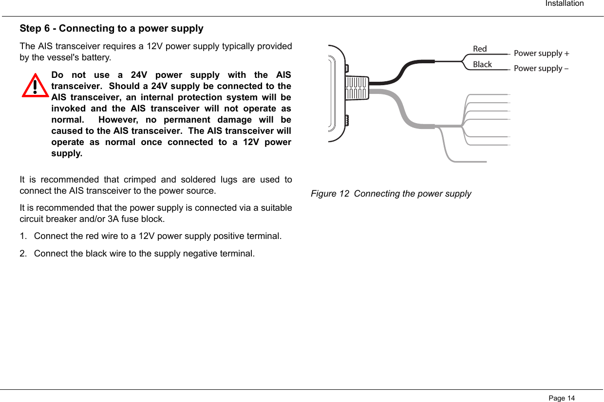
 403-0002 Class B AIS Transceiver User Manual Neon Manual Book v1 5

Software Radio Technology plc Class B AIS Transceiver Neon Manual Book v1 5

Contents

user manual

Class B AIS transceiver instruction manualNeon manual v1.4
Thank you for buying this AIS Class B transceiver.This product has been engineered to offer you the highest level of performance and durability and we hope that it will provide many years of reliable service. We constantly strive to achieve the highest possible quality standards, should you encounter any problems with this product, please contact your dealer who will be pleased to offer whatever assistance you require.
1 Notices ..................................................................................................11.1 Safety warnings......................................................................................11.2 General notices ......................................................................................12 About your AIS class B transceiver ...................................................32.1 About AIS ...............................................................................................32.2 Static and dynamic vessel data..............................................................32.3 Important information for US customers.................................................42.4 What's in the box? ..................................................................................53 Installation ............................................................................................73.1 Preparing for Installation ........................................................................73.2 Installation procedures ...........................................................................94 Configuring your AIS transceiver .....................................................154.1 Switching on your AIS transceiver for the first time..............................154.2 Introduction to the proAIS software ......................................................164.3 Installing the proAIS software...............................................................164.4 Configuration using proAIS ..................................................................175 Operation ............................................................................................195.1 Using the AIS transceiver.....................................................................195.2 Switch functions ...................................................................................195.3 Using proAIS with your AIS transceiver ...............................................205.4 Indicator functions ................................................................................236 Troubleshooting .................................................................................247 Specifications .....................................................................................258 Warranty..............................................................................................26Figure 1 Items included in the product..................................................... 5Figure 2 AIS transceiver overview ........................................................... 6Figure 3 Electrical connections to the AIS transceiver ............................ 6Figure 4 Typical installation configuration................................................ 7Figure 5 AIS transceiver dimensions ..................................................... 10Figure 6 AIS transceiver mounting ........................................................ 10Figure 7 GPS antenna mounting ........................................................... 11Figure 8 Position of the GPS antenna connector .................................. 11Figure 9 Position of the VHF antenna connector................................... 12Figure 10 Connecting an external switch................................................. 12Figure 11 Connecting to the NMEA0183 data port.................................. 13Figure 12 Connecting the power supply .................................................. 14Figure 13 Indicator start up sequence ..................................................... 15Figure 14 Entering static data into proAIS ............................................... 16Figure 15 proAIS GPS status page ......................................................... 20Figure 16 proAIS Diagnostics page ......................................................... 21Figure 17 proAIS Other vessels page...................................................... 21Figure 18 proAIS Messages page ........................................................... 22Figure 19 proAIS Serial data page .......................................................... 22Figure 20 Indicator location on the AIS transceiver unit .......................... 23Table of contents Table of figures
 NoticesPage 11 Notices1.1 Safety warnings1.2 General noticesPosition sourceAll marine Automatic Identification System (AIS) transceivers utilisea satellite based location system such as the Global PositioningSatellite (GPS) network.  The accuracy of a GPS position fix is variable and is affected byfactors such as the antenna positioning, how many satellites areused to determine a position and how long satellite information hasbeen received for.Compass safe distanceThe compass safe distance of this unit is 0.5m or greater for 0.3°deviation.RF emissions noticeCaution: The AIS transceiver generates and radiates radiofrequency electromagnetic energy. This equipment must beinstalled and operated according to the instructions contained in thismanual. Failure to do so can result in personal injury and / or AIStransceiver malfunction.  Caution: Never operate the AIS transceiver unless it is connected toa VHF antenna.  To maximise performance and minimise human exposure to radiofrequency electromagnetic energy you must make sure that theantenna is mounted at least 1.5 meters away from the AIStransceiver and is connected to the AIS transceiver before power isapplied.  The system has a Maximum Permissible Exposure (MPE) radius of1.5m. This has been determined assuming the maximum power ofthe AIS transceiver and using antennas with a maximum gain of3dBi.The antenna should be mounted 3.5m above the deck in order tomeet RF exposure requirements.  Higher gain antennas will requirea greater MPE radius.Do not operate the unit when anyone is within the MPE radius of theantenna (unless they are shielded from the antenna field by agrounded metallic barrier).!When reading this manual please pay attention towarnings marked with the warning triangle shown onthe left.  These are important messages for safety,installation and usage of the product.!This equipment must be installed in accordance withthe instructions provided in this manual.!This equipment is intended as an aid to navigation andis not a replacement for proper navigational judgement.!Do not install this equipment in a flammableatmosphere such as in an engine room or near to fueltanks.
 NoticesPage 2The antenna should not be co-located or operated in conjunctionwith any other transmitting antenna.The required antenna impedance is 50 ohms.WarrantyThis product is supplied with standard warranty as defined insection 8.  Disposal of this product and packagingPlease dispose of the AIS transceiver in accordance with theEuropean WEEE Directive or with the applicable local regulationsfor disposal of electrical equipment.  Every effort has been made to ensure the packaging for this productis recyclable.  Please dispose of the packaging in anenvironmentally friendly manner.  Accuracy of this manualThe AIS transceiver may be upgraded from time to time and futureversions of the AIS transceiver may therefore not correspondexactly with this manual.  Information contained in this manual isliable to change without notice.  The manufacturer of this productdisclaims any liability for consequences arising from omissions orinaccuracies in this manual and any other documentation providedwith this product.  Declaration of conformityThe manufacturer of this product declares that this product is incompliance with the essential requirements and other provisions ofthe R&TTE directive 1995/5/EC.  The product carries the CE mark, notified body number and alertsymbol as required by the R&TTE directive.  The product is intended for sale in the following member states:Great Britain, France, Spain, Sweden, Austria, Netherlands,Portugal, Denmark, Norway, Belguium, Italy, Finland, Ireland,Luxembourg, Germany, Czech Republic.  FCC noticeThis equipment has been tested and found to comply with the limitsfor a Class B digital device, pursuant to part 15 of the FCC Rules.These limits are designed to provide reasonable protection againstharmful interference in a residential installation.  This equipment generates, uses and can radiate radio frequencyenergy and, if not installed and used in accordance with theinstructions, may cause harmful interference to radiocommunications. !Any attempt to tamper with or damage this product willinvalidate the warranty. !WARNING: It is a violation of the rules of the FederalCommunications Commission to input an MMSI thathas not been properly assigned to the end user, or tootherwise input any inaccurate data in this device.
 About your AIS class B transceiverPage 32 About your AIS class B transceiver2.1 About AISThe marine Automatic Identification System (AIS) is a location andvessel information reporting system. It allows vessels equipped withAIS to automatically and dynamically share and regularly updatetheir position, speed, course and other information such as vesselidentity with similarly equipped vessels.  Position is derived from theGlobal Positioning System (GPS) and communication betweenvessels is by Very High Frequency (VHF) digital transmissions. There are a number of types of AIS device as follows:•Class A transceivers.  These are similar to Class B transceiver,but are designed to be fitted to large vessels such as cargo shipsand large passenger vessels.  Class A transceivers transmit at ahigher VHF signal power than class B transceivers and thereforecan be received by more distant vessels, and also transmitsmore frequently.  Class A transceivers are mandatory on allvessels over 300 gross tonnes on international voyages andcertain types of passenger vessels under the SOLAS mandate.   •Class B transceivers.  Similar to Class A transceivers in manyways, but are normally lower cost due to the less stringentperformance requirements.  Class B transceivers transmit at alower power and at a lower reporting rate than Class Atransceivers.  •AIS basestations.  AIS basestations are used by Vessel TrafficSystems to monitor and control the transmissions of AIStransceivers.  •Aids to Navigation (AtoN) transceivers.  AtoNs aretransceivers mounted on buoys or other hazards to shippingwhich transmit details of their location to the surrounding vessels.  •AIS receivers.  AIS receivers will generally receivetransmissions from Class A transceivers, Class B transceivers,AtoNs and AIS basestations but do not transmit any informationabout the vessel on which they are installed.  2.2 Static and dynamic vessel dataThere are two categories of information transmitted by anAIS transceiver: static and dynamic data.The vessel's dynamic data, which includes location, speed overground (SOG) and course over ground (COG), is calculatedautomatically using the internal GPS receiver.  Static data is information about the vessel which must beprogrammed into the AIS transceiver.  This includes:• Maritime Mobile Service Identity (MMSI)• Vessel name• Vessel call sign (if available)• Vessel type• Vessel dimensionsIn most countries the operation of an AIS transceiver is includedunder the vessel's marine VHF licence provisions. The vessel on to
 About your AIS class B transceiverPage 4which the AIS unit is to be installed must therefore possess acurrent VHF radiotelephone licence which lists the AIS system,vessel Call Sign and MMSI number.  2.3 Important information for US customersThere are specific laws in the USA regarding the configuration ofAIS class B transceivers.  If you are a US resident and intend to use your AIS class Btransceiver in US waters, you should make sure that your retailerhas configured your product prior to supplying it to you.  If your AIStransceiver has not been pre-configured please contact your dealerfor details of how to have it configured.  !An MMSI number is required in order for the AIStransceiver to operate.  Please contact the relevantauthority in your country for more information. !In the United States of America, the MMSI and staticdata must only be entered by a competent installer.The end user of the equipment is not authorised toenter their own static data.
 About your AIS class B transceiverPage 52.4 What's in the box?Figure 1 shows the items included with your AIS transceiverpurchase.  The following sections give a brief overview of each item.Please ensure all items are present and if any of the items are notpresent contact your dealer.  Figure 1 Items included in the product• Support tools CDThe CD supplied with the package contains the proAIS software toolnecessary to configure the AIS transceiver.  Please refer to section4 for details of the configuration process and how to use the proAIStool.  • Quick start guideThe quick start guide gives a handy one page reference for theinstallation process.  • Product manualThis document is the product manual and should be read thoroughlyprior to any attempt to install or use the AIS transceiver.  • GPS antennaThe GPS antenna forms an integral part of the product's internalpositioning system based on GPS.  Please refer to section 3.2 fordetails of how to install the GPS antenna.  • Fixing screwsFour fixing screws are provided with the product for mounting of theAIS transceiver.  Please refer to section 3.2 for details of how tomount the AIS transceiver.  • AIS transceiver unitFigure 2 shows an overview of the AIS transceiver unit.  The AIS transceiver has a number of indicators which provideinformation to the user about the status of the AIS transceiver.Please refer to section 5.4 for more details of indicator functions.  The AIS transceiver has a single switch which can be configured toprovide certain functions as defined in section 5.2.  Screws(packet of 4)Product CDQuickstart guideProduct manualGPS AntennaClass B AIS transceiver
 About your AIS class B transceiverPage 6Figure 2 shows the AIS transceiver mounting holes.  Please refer tosection 3.2 for details of how to mount the AIS transceiver.  Figure 2 AIS transceiver overviewElectrical connectionsThe AIS transceiver has the following connections provided by theattached cables:• Power supply• NMEA0183 data port for connection to chart plotters• RS232 for connection to a PC• External switch inputIn addition there are two other connections for the GPS antennaand the VHF antenna.  Figure 3 Electrical connections to the AIS transceiver!Do not attempt to adjust or remove the fixings next toeach of the four mounting holes.  These fixings formpart of the sealing of the AIS transceiver and anymodification could affect the product's performanceand will invalidate the product's warranty. Indicator lightsSwitchMountingholesMountingholesBlue Red Amber GreenPower and data cablesVHF antenna connector GPS antenna connectorPlotterPower inSwitch RS232Class B AIS transceiver
 InstallationPage 73 Installation3.1 Preparing for InstallationFigure 4 shows a typical installation configuration for the AIStransceiver.  Please take the time to familiarise yourself with thesystem elements and their connections prior to attemptinginstallation.  Figure 4 Typical installation configurationIn addition to the items provided with your AIS transceiver thefollowing items will be required for installation:VHF antennaConnection to a suitable VHF antenna will be required for the AIStransceiver to operate.  A standard marine band VHF antenna suchas that used with VHF voice radios will be sufficient.  Please takenote of the warnings in section 1 regarding the use of antennas.Alternatively, if you wish to use an existing VHF antenna, antennasplitter products are available which allow the existing antenna to beused with two radio devices, such as a VHF voice radio and the AIStransceiver.   Antenna cablesThe GPS antenna is provided with 10 metres of cable.  If this is notsufficient to reach between the desired GPS antenna location andthe AIS transceiver unit you will need an extension cable.  Pleasecontact your dealer for details.  For reference the GPS antennaconnector type on the AIS transceiver unit is TNC receptacle, and isintended to mate with a TNC jack connector.  SwitchPower inRS232GPS AntennaClass B AIS transceiverChartplotterVHF Antenna!When selecting an AIS antenna splitter make sure it iscapable of operation with an AIS transceiver.  Some AISantenna splitters are designed to work only with AISreceivers.  Please check with your dealer to ensure youpurchase the correct type of antenna splitter.
 InstallationPage 8Please check that the VHF antenna you intend to use has sufficientcable to reach between the VHF antenna and the AIS transceiverunit.  If it is not sufficient you will need an extension cable.  Pleasecontact your dealer for details of suitable products.  For referencethe VHF antenna connector type on the AIS transceiver unit is SO239, and is intended to mate with a PL 259 connector.  Power and data cablesThe AIS transceiver unit is supplied with a one metre long powerand data cable as an integral part of the AIS transceiver unit.  If yourequire longer cables to reach your power supply, please ensure thecables are capable of carrying currents of up to 2A peak and 500mAon average.  Means of connecting the cables together will also berequired.  The use of ScotchlokTM connectors is recommended forthis purpose.  Chart plotterTo display received AIS messages as other vessels on your chartplotter, you will need to connect your AIS transceiver to your chartplotter.  Please refer to the user manual supplied with your chatplotter for details of how to connect and configure your chart plotterfor use with AIS devices.  For general guidance your chart plottershould be configured to accept NMEA data at 38400 baud(sometimes referred to as 'NMEA HS' in the plotter configurationmenu).  You may also need to enable the display of AIS targets inthe chart options.  Connection to a PCIf you choose to use a PC with suitable charting software to displayreceived AIS messages as other vessels, this can be accomplishedby connecting the RS232 directly to the PC, or via a suitable RS232to USB converter if your PC does not have a RS232 port.  GPS antenna mountA one inch 14 TPI pole mount is required to mount the suppliedGPS antenna.  Please contact your dealer for details of suitableproducts.
 InstallationPage 93.2 Installation proceduresBefore beginning installation of your AIS transceiver, please ensureyou have the necessary additional items as detailed in section 3.1.It is strongly recommended that you read all of the instructions inthis manual prior to installation.  If after reading this manual you are unsure about any element of theinstallation process please contact your dealer for advice.  The following sections explain the installation process step by stepfor each of the main elements of the system.  Step 1 - Installing the AIS transceiverPlease note the following guidelines when selecting a location foryour AIS transceiver:• The AIS transceiver must be fitted in a location where it is at least0.5m from a compass or any magnetic device.  • There should be adequate space around the AIS transceiver forrouting of cables.  See Figure 5 for details of the AIS transceiverdimensions.  • The ambient temperature around the AIS transceiver should bemaintained between -10°C and +55°C.  • The AIS transceiver should not be located in a flammable orhazardous atmosphere such as in an engine room or near to fueltanks.  • The AIS transceiver is fully waterproof to ingress protectionrating IPx7, however it is recommended that the AIS transceiveris not subjected to extended periods of exposure to spray orsubmersion.  • It is recommended that the AIS transceiver is installed in a 'belowdecks' environment.  • It is acceptable to mount the AIS transceiver either vertically orhorizontally.  • The product is supplied with four self tapping screws forattachment of the AIS transceiver to a suitable surface.  Pleaserefer to Figure 6 for guidance.   • The AIS transceiver should be mounted in a location where theindicators are readily visible as these provide importantinformation on the status of the AIS transceiver.
 InstallationPage 10 Figure 5 AIS transceiver dimensions Figure 6 AIS transceiver mounting 215 mm84 mm185 mm150 mm137 mm 45 mm
 InstallationPage 11Step 2 - Installing the GPS antennaFor mounting of the GPS antenna provided with your AIStransceiver you will require a one inch 14 TPI thread pole.  You should ensure the GPS antenna has a good clear view of theentire sky.  It is not recommended that the GPS antenna is mounted up a mastwhere the the motion of the vessel will cause the antenna to swingand potentially reduce the accuracy of the GPS position.  Do not mount your antenna in the direct path of a radar transmitter.  Feed the ten metre long cable attached to the GPS antenna cablethrough the pole and screw the antenna onto the pole mount asshown in Figure 7.  Route the cable to your AIS transceiver unit, adding any necessaryextension cables.  Connect the cable from the GPS antenna to the GPS connector onthe AIS transceiver as shown in Figure 8.   Figure 7 GPS antenna mountingFigure 8 Position of the GPS antenna connectorGPS AntennaVHF Antenna
 InstallationPage 12Step 3 - Connecting the VHF antennaRoute the cable from the VHF antenna to the AIS transceiver andconnect to the VHF connector on the AIS transceiver as shown inFigure 9.  A standard marine band VHF antenna or AIS antenna should beused with the AIS transceiver.  The connector type on the AIStransceiver is SO239.  Your chosen VHF antenna requires a PL259connector to mate with this.  If your VHF antenna does not use thistype of connector please contact your dealer for details of availableadaptors.  Figure 9 Position of the VHF antenna connectorStep 4 - Connecting an external switchIf you require a remote external switch to activate the silent modefeature, it is possible to connect a toggle switch to the AIStransceiver and configure the switch function accordingly.Connect the toggle switch between the orange and blue wires asshown in Figure 10 and configure the switch function in proAIS to'Make switch to disable transmitter'. For more details on how to dothis please refer to section 4.4.  Connection of an external switch to toggle silent mode is optionaland not essential for normal operation of the product.    Figure 10 Connecting an external switchGPS AntennaVHF AntennaYellowBrownWhiteGreenTransmit +Transmit –Receive +Receive –External switchconnectionBlueOrange
 InstallationPage 13Step 5 - Connecting to a chart plotterThe NMEA0183 data port provides the connection to your chartplotter and consists of four wires colour coded as shown in the tablebelow and in Figure 11.  Connect the wires to the appropriateconnections on your chart plotter.  Please refer to your chart plottermanual for more information.  N.B. The NMEA0183 data port operates at a baud rate of 38400.Please ensure your chart plotter is configured to receive data fromthe AIS transceiver via its NMEA0183 port at 38400 baud.  Please note that the 'Receive' connections may not be neededwhen connecting to your chart plotter as it is not normal for thetransceiver to receive data from the chart plotter.  Connecting an optional NMEA0183 deviceIf you wish to connect a NMEA0183 device (such as a headingsensor) to your chart plotter, but your chart plotter only has a singleNMEA0183 input, it is possible to use the AIS transceiver’sNMEA0183 multplexing feature to connect both devices to the chartplotter.  To multiplex your NMEA0183 device data via the AIS transceiversimply connect the device’s NMEA0183 output to the receive+ andreceive- terminals as defined in the table above.  Follow theinstructions in section 4.4 to configure the AIS transceiver tomultiplex the devices NMEA0183 data to your chart plotter.  Figure 11 Connecting to the NMEA0183 data portConnection to a PCThe AIS transceiver is supplied with an RS232 port for connectionto a PC.  The RS232 connector can be connected directly to theRS232 port on the PC or via a serial to USB converter if no RS232port is available.  For configuration of the AIS transceiver it isnecessary to connect to a PC if your AIS transceiver has not beenpre-configured by your dealer.  See section 4 for more details ofconfiguration.  NMEA0183 function Wire colourTransmit + YellowTransmit - BrownReceive + WhiteReceive - GreenYellowBrownWhiteGreenTransmit +Transmit –Receive +Receive –External switchconnectionBlueOrange
 InstallationPage 14Step 6 - Connecting to a power supplyThe AIS transceiver requires a 12V power supply typically providedby the vessel's battery.  It is recommended that crimped and soldered lugs are used toconnect the AIS transceiver to the power source.  It is recommended that the power supply is connected via a suitablecircuit breaker and/or 3A fuse block.  1. Connect the red wire to a 12V power supply positive terminal.  2. Connect the black wire to the supply negative terminal.Figure 12 Connecting the power supply!Do not use a 24V power supply with the AIStransceiver.  Should a 24V supply be connected to theAIS transceiver, an internal protection system will beinvoked and the AIS transceiver will not operate asnormal.  However, no permanent damage will becaused to the AIS transceiver.  The AIS transceiver willoperate as normal once connected to a 12V powersupply. RedBlackPower supply +Power supply –
 Configuring your AIS transceiverPage 154 Configuring your AIS transceiver4.1 Switching on your AIS transceiver for the first timeA few seconds after applying power to the AIS transceiver for thefirst time all four indicators (green, amber, red and blue) will blinktwice.  The indicator sequence following this will depend on whetheryour transceiver is pre-configured.  Transceiver is pre-configured:The amber indicator will illuminate until the transceiver hastransmitted an AIS message.  Transceiver is not pre-configured:The amber and red indicator will illuminate.  This indicates the unitcannot transmit until it is configured with a valid MMSI.  Figure 13 Indicator start up sequencePrior to use the AIS transceiver requires programming with thevessel's static data to ensure that the data transmitted by the AIStransceiver matches that of the host vessel.  Indicator lightsBlue Red Amber Green!US Customers only: It is a violation of the rules of theFederal Communications Commission for the end userto programme the static data.  The static data must onlybe programmed by a competent installer.  If your AIStransceiver has not been preconfigured for you pleaserefer to your dealer for advice on how to have the AIStransceiver configured by a competent installer.
 Configuring your AIS transceiverPage 164.2 Introduction to the proAIS softwareIncluded in the CD supplied with your product is a configurationsoftware tool called 'proAIS'.  proAIS is a software tool which provides the facility to configure,monitor and diagnose issues with your AIS transceiver.  Section 4.3 provides instructions on how to install the proAISsoftware.  Section 4.4 describes how to use proAIS to configure the static dataand other settings for your AIS transceiver.  Section 5.3 describes how to use proAIS to monitor the status ofyour AIS transceiver.  4.3 Installing the proAIS softwareThis software is designed to be installed and used with a PCconnected to the AIS transceiver via the data lead provided asstandard with the AIS transceiver unit. If the PC being used forprogramming does not have a 9-pin serial port then a commerciallyavailable USB to serial adaptor may be required. This connectsbetween the supplied data lead and the PC.  To install proAIS on your PC:1. Locate and run the setup.exe file on the CD and then follow theon-screen prompts.2. If a security warning appears, click 'Install' to continue with theinstallation. 3. Once installation is complete, proAIS will launch automaticallyand a start menu folder and shortcut will be created for future use. 4. Once proAIS has launched you should see a window as shownin Figure 14.  5. Please follow the instructions in section 4.4 to configure yourAIS transceiver.  Figure 14 Entering static data into proAIS!proAIS is only compatible with Windows  basedoperating systems and is not compatible with AppleMAC  operating systems.
 Configuring your AIS transceiverPage 174.4 Configuration using proAISFollow the steps below to configure the AIS transceiver:  1. Connect your AIS transceiver to the PC using the RS232 lead asdescribed in section 3.2.  Apply 12V power to the AIS transceiver asdescribed in section 3.2. 2. Select the appropriate serial port in proAIS and press 'Connect'.  3. proAIS should launch with the 'static data' page active (seeFigure 14).  If this is not the case please select the 'static data' page.  4. Carefully enter the data fields on the screen including:• MMSI - the vessel's MMSI must be 9 digits in length and shouldbe the same as that used for any other digital radio equipmentsuch as a VHF DSC radio.  • Ship's name - the ship's name can be up to 20 characters inlength.  • Call sign - the call sign can be up to seven characters in length.Not all vessels are issued with a call sign and it is acceptable toleave this field blank.  • Vessel type - select a vessel type from the drop down list whichmost closely matches your vessel.• GPS antenna location - use the on-screen guide to specify thedistances from your GPS antenna to the edges of the vessel asshown.  The distances are entered in metres.  5. Select the desired switch from the following options:• Press switch to send safety related message.• Make switch to disable transmitter (This is required if you intendto use an external toggle switch to control silent mode).• Press switch to toggle transmitter on/off (This is required if youintend to use the integrated switch to toggle silent mode).• Switch has no function.Please note: the integrated switch can only provide one of thesefunctions at any one time.  If you wish to change the function of theswitch please return to this configuration process.  6. Set the blue indicator function.  • The blue indicator can be configured to show either the status ofthe switch or to show when AIS messages are being receivedfrom other vessels.  • Note that the blue indicator cannot perform both functionssimultaneously.  !Please ensure that you enter all static data accurately.Failure to do so could result in other vessels failing toidentify your vessel correctly.!The vessel MMSI can only be programmed once usingproAIS, please take care to programme your MMSIcorrectly.  If you need to change the MMSI for anyreason, please contact your dealer who will arrange tohave the MMSI reset.
 Configuring your AIS transceiverPage 187. Set the baud rates to the required level for each of the serialports. • Set the RS232 baud rate to the required level.  The default is38,400.  This is the baud rate used when communicating with aPC via the RS232 connection.  • Set the NMEA output (transmit) baud rate to the required level.The default is 38,400.  This is the baud rate used whentransmitting data to a chart plotter via its NMEA0183 input.  • Set the NMEA input (receive) baud rate to the required level.The default is 4,800.  If you are using an optional NMEA0183device such as a heading sensor (see section 3.2) please selectthe baud rate at which the NMEA0183 device is transmittingdata.  If you are not using an optional NMEA0183 device thisbaud rate should be set to the same level as the NMEA transmitbaud rate.  7. Once all data has been entered correctly, press 'Save static datato AIS unit'.  This will permanently store the data to the unit.  8. You will see a pop-up window warning you that the MMSI canonly be entered once and should therefore be entered correctly.Please double check you have entered the correct MMSI.  9. All other static data can be modified by repeating the stepsabove.  10. If you need to change the MMSI for any reason please contactyour dealer who will be able to reset the unit.
 OperationPage 195 Operation5.1 Using the AIS transceiverOnce the unit has been configured it is ready for use.  Providingother vessels with AIS transceivers installed are within radio rangeof your vessel you should see their details appear on your chartplotter or PC.  These vessels will also be able to see your vessel ontheir chart plotter or PC.  It may take up to six minutes for your fullvessel details to be visible to others. Specific details of how to configure your chart plotter to make use ofthe AIS transceiver features will be given in your chart plottermanual.  If you are using charting software running on a PC, pleaserefer to the instructions provided with your chart plotting software fordetails of how to configure it to display AIS information.  5.2 Switch functionsThe integrated switch on the top of the unit (see Figure 2) can beconfigured either to trigger transmission of a "Safety RelatedMessage" or to place the unit into "Silent mode". This choice ismade during configuration of the unit using the proAIS application;please refer to 4.4 for further information on the configurationoptions.Safety related messageWhen configured to transmit a safety related message (SRM) theswitch will initiate broadcast of an AIS message containing thevessels MMSI along with the text "MAYDAY MAYDAY". The switchmust be pressed for at least two seconds to initiate this transmission(to avoid accidental activation) and the blue indicator will illuminateto indicate the message has been sent. Further safety relatedmessages cannot be sent until the blue indicator has extinguishedwhich will occur one minute after an SRM has been sent.Silent modeWhen configured to place the unit into "Silent mode", each press ofthe switch will toggle the AIS transmitter on or off. The switch mustbe depressed for two seconds to activate silent mode to avoidaccidental activation. When the transmitter is off, the amber andblue indicators will be illuminated and the AIS transceiver's positionwill not be broadcast to other vessels. The position of other vesselswill still be received by the unit.Silent mode can be used if you wish to only receive AIS messagesfrom other vessels but keep your own details private from other AISusers.   !The SRM function is not a primary means of distresscall and cannot be relied upon as a means of distresscall.   !Your vessel will not be displayed on other users, chartplotters or PCs while your AIS transceiver is in silentmode.
 OperationPage 205.3 Using proAIS with your AIS transceiverThe proAIS tool has a range of features to help monitor theperformance of your AIS transceiver.  To use the full range offeatures your AIS transceiver must be installed as described insection 3 and connected to a PC running the proAIS application.  proAIS menusThis section describes the functions available via the proAISmenus.  The proAIS 'File' menu includes the following functions:Open log file - this includes the ability to open a log file previouslycaptured using the log file capture tool.The proAIS 'Options' menu includes the following functions:Beep on AIS transmission - the PC will make an audible beepwhen an AIS message is transmitted.Force connection - forces proAIS to make a connection with theAIS unit even when no response is received from the unit.The proAIS 'Help' menu includes the following functions:About - details of the version number of the proAIS software youhave installed.proAIS GPS status pageThe 'GPS status' page shows the signal strength of each satellitebeing received and the dynamic data of the vessel.  Satellite signalsshown as green bars are actively being used calculate a position fix.If position fix cannot be achieved then no dynamic data will beshown and all signal strength bars will be blue.   Figure 15 proAIS GPS status page
 OperationPage 21proAIS Diagnostics pageThe 'Diagnostics' page provides a range of information about theAIS transceiver's status.  Referring to the information in this pagemay be useful if you are attempting to diagnose a potential issuewith the AIS transceiver's installation or operation.   Figure 16 proAIS Diagnostics page proAIS Other vessels pageThe 'Other vessels' page provides a list of all vessels from whichAIS messages are being received.  For each vessel the MMSI,name, call sign, speed and course, position, range and bearing areshown if available.   Figure 17 proAIS Other vessels page
 OperationPage 22proAIS Messages pageThe 'Messages' page provides a list of all text messages receivedfrom other vessels.  These are most likely to be safety relatedmessages which are requests for assistance from other vessels.   Figure 18 proAIS Messages page proAIS Serial data pageThe 'Serial data' page provides a view of all incoming and outgoingAIS messages.  The messages are encoded in a special format andit is not necessary to understand the meaning of the messages touse the equipment.  The serial data page includes the facility tocapture your AIS data during a journey and then play it back usingthe 'open log file' command in the 'File' menu.   Figure 19 proAIS Serial data page
 OperationPage 235.4 Indicator functionsThe AIS transceiver includes four coloured indicators as shown inFigure 20.  The state of the indicators provides informationregarding the status of the AIS transceiver.   Figure 20 Indicator location on the AIS transceiver unitThe meaning of typical indicator configurations is shown in the tablebelow and Figure 20 shows the orientation of the AIS transceiver.  The AIS transceiver is powered up, has a position fix andhas transmitted at least one vessel information report.  The AIS transceiver has detected a system error.  Thelikely causes of this are detailed in the troubleshootingguide in section 6.Indicator lightsBlue Red Amber GreenWhen the switch function is configured to activate thesilent mode feature and the switch has been depressedfor more than two seconds, this combination of indicatorswill be illuminated to show that the transmitter is disabled.  This arrangement of indicators will also be visible if theAIS transceiver has been configured for the blue indicatorto signify received AIS messages.  In this case the blueindicator will rapidly turn on and off as messages arereceived.  The AIS transceiver is in 'transmit timeout' mode.  Thiscan be for a number of reasons:  • The unit has only recently been powered on and isobtaining a position fix prior to transmitting its firstvessel information report.  (This process can takeseveral minutes).• Position fix has been lost.  The AIS transceiver willattempt to regain position fix for 30 minutes beforeentering an error state.  • The AIS radio channels are exceptionally busy sothere is currently no available timeslot fortransmission.  • The unit has been in silent mode and after deactivatingsilent mode this amber indicator will illuminate until thefirst AIS message has been sent•The AIS transceiver has been commanded by thelocal authority (via an AIS Basestation) to ceasetransmissions.  When the switch function is configured to activate safety related messages and the switch has been depressed for more than two seconds the blue indicator will illuminate for 1 minute.  It is not possible to send a safety related message at a rate of more than once per minute.
 TroubleshootingPage 246 TroubleshootingIf the guidance given in the table above does not rectify the problemyou are experiencing, please contact your dealer for furtherassistance.  Issue Possible cause and remedyNo data is being receivedby the chart plotter• Check that the power supply is connectedcorrectly.  • Check that the power supply is a 12V supply.  • Check that the connections to the chart plotter arecorrect.  No indicators are illuminated• Check that the power supply is connectedcorrectly.  • Check that the power supply is a 12V supply.  The Red 'error' indicatoris illuminated• The unit may not have a valid MMSI.  Check thatthe AIS transceiver is correctly configured with avalid MMSI.  • The VHF antenna may be faulty.  Please checkthe connection to the VHF antenna and that theVHF antenna is not damaged.  The red indicatormay illuminate briefly if the power supply isinterrupted or the VHF antenna characteristics arebriefly affected.  • The GPS antenna may be faulty.  Please checkthe connection to the GPS antenna and that theGPS antenna is not damaged.  • The power supply is outside the allowable range.Check that the power supply is within the range9.6V to 15.6V.  • If none of the above correct the error conditionplease contact your dealer for advice.  My MMSI is beingreceived by other vesselsbut my vessel name isnot shown on their chartplotter or PC• Some older AIS devices and chart plotters do notprocess the specific class B AIS message whichprovides the vessel name (message 24).  This isnot a fault of your AIS transceiver.  Softwareupgrades are available for many older chartplotters which will correct this issue.  The othervessel should update its AIS unit and/or chartplotting software to receive AIS message 24.
 SpecificationsPage 257 SpecificationsParameter ValueDimensions 215 x 150 x 45 mm (L x W x H)Weight 685g (AIS transceiver unit only)Power DC (9.6V - 15.6V)Average power consumption 4WPeak current rating 2AGPS Receiver (AISInternal)16 channel IEC 61108-1 compliantElectrical Interfaces RS232 38.4kBaud bi-directionalRS422 NMEA 38.4kBaud bi-directionalConnectors VHF antenna connectorGPS antenna connectorRS232/RS422/Power/External switchVHF Transceiver Transmitter x 1Receiver x 2  (One receiver time sharedbetween AIS and DSC)Frequency: 156.025 to 162.025 MHz in25 kHz stepsOutput Power 33dBm ± 1.5 dBChannel Bandwidth 25kHzChannel Step 25kHzModulation Modes 25kHz GMSK (AIS, TX and RX)25kHz AFSK (DSC, RX only)Bit rate 9600 b/s ± 50 ppm (GMSK)1200 b/s ± 30 ppm (FSK)RX Sensitivity Less than -107dBm at 20% PERCo-channel 10dBAdjacent channel 70dBIMD 65dBBlocking 84dBEnvironmental Water resistant to IPx7 Operating temperature: -25ºC to +55ºCTested to IEC 60945 'Protected' categoryIndicators Power, TX timeout, error, statusOperator Controls Single switch configurable to enableeither silent mode or safety relatedmessage functions
 WarrantyPage 268 WarrantyWhat this warranty coversThe Manufacturer of this Product warrants to the Buyer that theProduct will be free from defects under normal use ("Defects") for aperiod of two (2) years from the date that the Product waspurchased ("Warranty Period").  What this warranty does not coverThe Limited Warranty does not apply to normal wear and tear, doesnot apply when the Product is opened or repaired by someone notauthorised by the Manufacturer and does not cover repair orreplacement of any element of the Product damaged by misuse,moisture, exposure to heat, abuse or failure to comply with theinstructions supplied with the Product.  How to make a warranty claimIn order to make a claim of a Defect, you must contact theManufacturer during the Warranty Period to explain the Defect andto obtain an RMA number (Return Materials Authorisation) ifnecessary. You must return the Product during the Warranty Period(at your own expense), along with an explanation of the Defect, tothe address provided to you by the Manufacturer.  If the Warrantyclaim is deemed to be valid the Manufacturer will reimburse to youthe cost of shipping and return the Product to you after repair.  Your legal rightsThis Limited Warranty does not affect any legal rights underapplicable national legislation governing the sale of consumergoods.  This Limited Warranty cannot be transferred to any otherperson.  Limitation of liabilityThe Manufacturer and its suppliers shall not be liable to you or toany third party for any damages either direct, indirect, consequentialor otherwise including but not limited to damages for the inability touse the equipment arising out of the use of or inability to use theProduct.  The entire liability of the Manufacturer and any of its suppliers shallbe limited to the amount actually paid by you for the Product.  Theprovisions of this Limited Warranty are in lieu of any other warranty,whether expressed or implied, written or oral.  The Manufacturerand its suppliers shall not be liable for any incidental, indirect,consequential or special (including punitive or multiple) damages,loss of profit, business, contracts, opportunity, goodwill or othersimilar loss.  Nothing in this Warranty shall limit the liability of the Manufacturer orits suppliers in respect of death or personal injury caused by itsnegligence, fraud or any other liability which by law cannot beexcluded or limited.

Navigation menu