Sam Ash Music HT7 Wireless Microphone Transmitter User Manual Concert77 ownman indd
Sam Ash Music Corporation Wireless Microphone Transmitter Concert77 ownman indd
Contents
- 1. User Manual
- 2. user manual
User Manual
WIRELESS

Table of Contents
Introduction / System Features 1
Guided Tour - CR77 Receiver Front Panel 3
Guided Tour - CR77 Receiver Rear Panel and Frequency Conversion Chart 4
Guided Tour - CT7L / CT7G Beltpack Transmitter 5
Guided Tour - HT7 Handheld Microphone Transmitter 7
Setting Up and Using the Concert SeriesSystem 8
Appendix A: CT7L Multipin Wiring Guide and Chart 11
Specifications 12
Copyright 2005, Samson Technologies Corp.
First Printed March 2005
Samson Technologies Corp.
575 Underhill Blvd.
P.O. Box 9031
Syosset, NY 11791-9031
Phone: 1-800-3-SAMSON (1-800-372-6766)
Fax: 516-364-3888
www.samsontech.com

1
Introduction / System Features
Congratulations on purchasing the Samson Concert Series UHF Wireless System! Although this
product is designed for easy operation, we suggest you first take some time to go through these
pages so you can fully understand how we’ve implemented a number of unique features.
Every wireless system consists of at least two components—a transmitter and a receiver, both of
which must be tuned to the same channel (that is, the same radio frequency) in order to operate
correctly.* The Samson Concert Series system you have purchased operates in the 801 - 805 MHz
frequency range and contains a CR77 receiver and either our CT7 belt-pack transmitter (for lava-
lier, wind instrument, headset microphone applications and instrument applications) or the HT7
hand-held microphone transmitter (available with the Samson Q7 dynamic or C05 condenser
capsules).
In this manual, you’ll find a detailed description of the features of the Concert Series Wireless
system, as well as a guided tour through all components, step-by-step instructions for setting up
your system, wiring diagrams and tables, and full specifications. If your Concert Series system
was purchased in the United States, you’ll also find a warranty card enclosed—don’t forget to
fill it out and mail it! This will enable you to receive online technical support and will allow us
to send you updated information about this and other Samson products in the future. If your
Concert Series Wireless system was purchased outside of the U. S., contact your local distributor
for warranty details.
SPECIAL NOTE for U.S. purchasers: Should your Concert Series Wireless system ever require servic-
ing, a Return Authorization number (RA) is necessary. Without this number, the unit will not be
accepted. If your Concert SeriesWireless system was purchased in the United States, please call
Samson at 1-800-372-6766 for a Return Authorization number prior to shipping your unit. If pos-
sible, return the unit in its original carton and packing materials. If your Concert SeriesWireless
system was purchased outside of the U. S., contact your local distributor for servicing information.
* Your receiver and transmitter have been factory preset to utilize the same channel. A listing of
the six available channels and their corresponding UHF frequencies can be found on page 4 of
this manual.
System Features
Designed for use in both live sound and sound contracting applications, the Samson Concert
Series Wireless System provides a high performance, cost effective solution, utilizing state-of-the-
art technology in wireless communications. Main features include:
• Six different available channels, all operating in the less crowded UHF bandwidth, and all
designed for simultaneous use. This means that you can use multiple Concert Series systems
(each tuned to a different channel) in the same location without interference.
• Technological breakthrough usage of Dielectric filters for extremely precise and stable tuning.
• Diversity technology maximizes active range (up to 300 feet) and reduces potential interference
problems.

2
System Features
• The CR77 receiver is a half-rack unit that can be used freestanding or can be mounted in any
standard 19" rack,* making it easy to integrate into any traveling or fixed installation audio
system. It includes a pair of tuned antennas and provides both balanced and unbalanced out-
puts, line/mic output level switch and continuously adjustable Volume and Squelch controls,
as well as an audio peak LED, dual antenna indicators, a six-segment Audio level meter and a
six-segment RF level meter.
• Built-in companding noise reduction in all components for crystal-clear sound with minimized
background noise and hiss.
• Transmitters provide “popless” muting (which turns off the audio signal while leaving the car-
rier signal on) and use standard 9-volt batteries, with battery life of more than 12 hours. The
Concert transmitters also provide a convenient Battery Strength LED meter, allowing you to
monitor the remaining power in the installed battery.
• The CT7 provides a mini-XLR jack for connection to the Samson GC5P3 cable with standard
1/4" jack (for use with instruments such as electric guitar or bass), or for connecting to a variety
of popular headsets and lavalier microphones, including:
Samson QE headset
**
Samson QV headset
Samson HS5P3 headset
Samson HM40P Wind Instrument Mic
Samson LM5P3 lavalier
Samson QL1 lavalier
Audio-Technica
ATM-75
headset
Audio-Technica
MT-350
lavalier
Applied Microphone Technology
Roaming One
wind instrument microphone
Audio-Technica
AT
-
831
lavalier
Countryman
IsoMax
headset
Sony
ECM-40
lavalier
Sony
ECM-44
lavalier
• The HT7 hand-held microphone transmitter is available with either the Samson
Q7
Neodymium dynamic microphone capsule, or the Samson
C05
Condender microphone cap-
sule.
• All components have rugged construction that ensures reliable operation in even the most
demanding performance environments.
* Using an optional Samson RK55 rack adapter kit
** Optimized for aerobics workouts, this headset is recommended for usage in high-humidity
environments such as physical fitness centers.
3
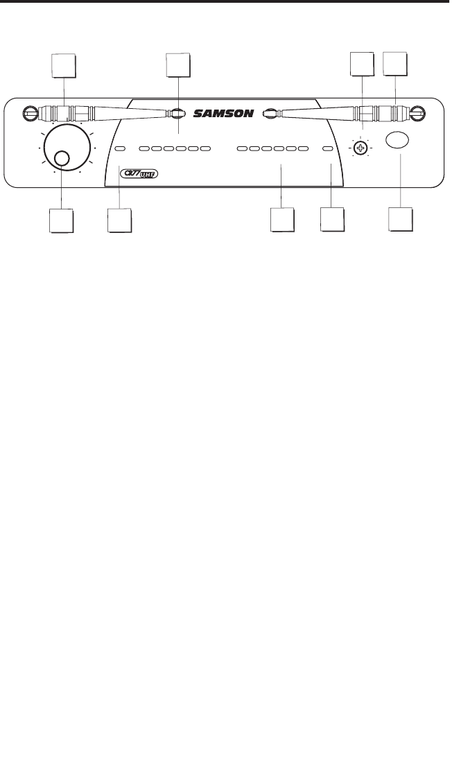
Guided Tour - CR77 Front Panel
1: Antennas (A and B)
- The antenna mountings allow full rotation for optimum placement. In
normal operation, both Antenna A (the antenna on the left) and Antenna B (the antenna on the
right) should be placed in a vertical position. Both antennas can be folded inward for conve-
nience when transporting the CR77. See the “Setting Up and Using the AirLine System” section
on page 17 in this manual for information about antenna installation and positioning.
2: Volume control
- This knob sets the level of the audio signal being output through both the
balanced and unbalanced output jacks on the rear panel (see #2 and #4 on page 8 in this manu-
al). Reference level is obtained when the knob is turned fully clockwise (to its “10” setting).
3: Audio Meter
- This “ladder” display (similar to the VU bar meter used on audio devices) indi-
cates the strength of the incoming audio signal. When the “0” segment is lit, the incoming signal
is optimized at unity gain; when the “+6” segment is lit, the signal is overloading. When only
the left-most “-20” segment is lit, the incoming signal is at just 10% of optimum strength. If no
segments are lit, little or no signal is being received. See the “Setting Up and the Concert Series
System” section on page 16 in this manual for more information.
4: Squelch control
- This control determines the maximum range of the CR77 before audio
signal dropout. Although it can be adjusted using the supplied plastic screwdriver, it should
normally be left at its factory setting. See the “Setting Up and Using the Concert Series System”
section on page 17 in this manual for more information.
5: A/B Antenna LEDs
- When signal is being received, one of these will be lit green, showing
you whether the (left) “A” or (right) “B” antenna is currently being used. The CR77 constantly
scans its two antennas and automatically selects whichever is receiving the strongest, clearest
signal. This
True Diversity
switching is completely inaudible, but it effectively increases overall
range while virtually eliminating potential interference and phase cancellation problems.
6: RF (Radio Frequency) Level meter
- This “ladder” display (similar to the VU bar meter used
on audio devices) indicates the strength of the incoming radio signal. When the “100%” segment
is lit, the incoming RF signal is fully modulated and at optimum strength. When only the second
most left-most “10%” segment is lit, the incoming signal is at just 10% of optimum strength.
If no segments are lit, little or no signal is being received. See the “Setting Up and Using the
Concert Series System” section on page 17 in this manual for more information.
8: Power switch
- Use this to turn the CR77 power on and off. When the receiver is on, the inter-
nal Power LED is lit.
1
2
34
55
1
7
6
4
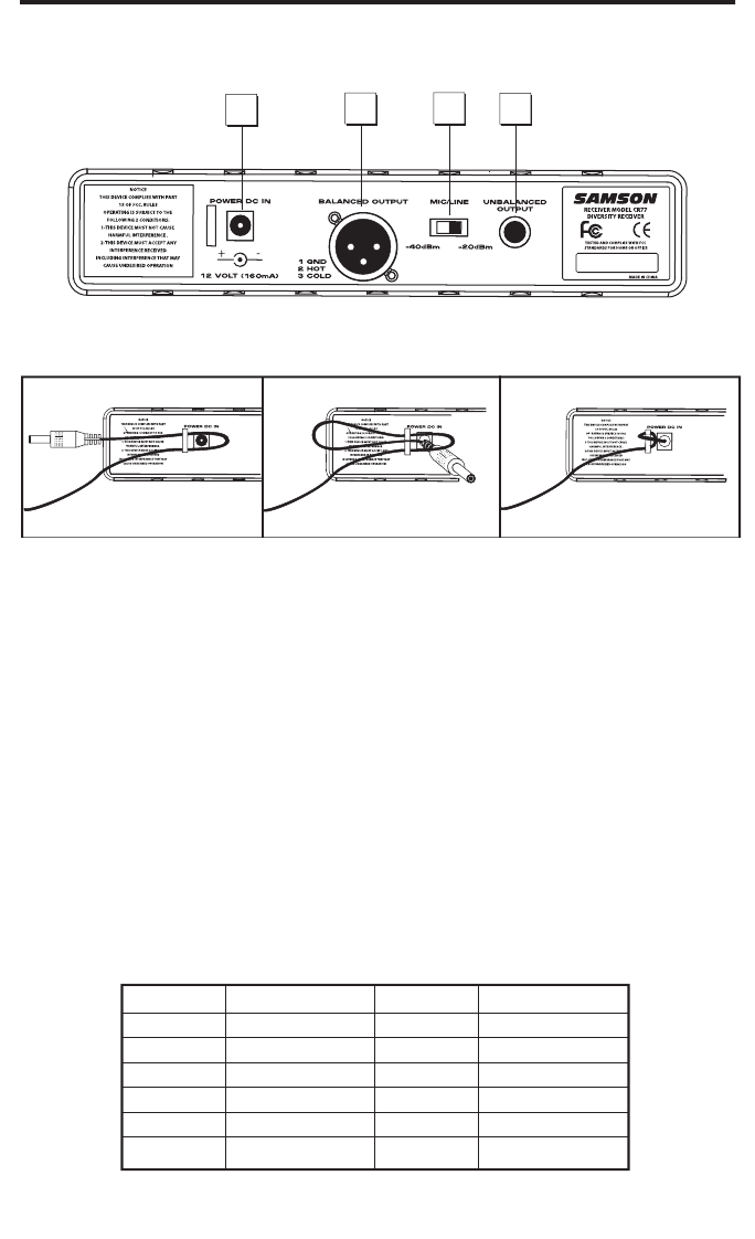
Guided Tour - CR77 Rear Panel
1: DC input
- Connect the supplied 12 volt 160 mA power adapter here, using the strain relief as
shown in the illustration below.
WARNING:
Do not substitute any other kind of power adapter;
doing so can cause severe damage to the CR77 and will void your warranty.
2: Balanced output*
- Use this electronically balanced low impedance (600 Ohm) XLR jack
when connecting the CR77 to professional (+4) audio equipment. Pin wiring is as follows: Pin 1
ground, Pin 2 high (hot), and Pin 3 low (cold).
3: Audio Output Level switch
- Sets the audio output level attenuation of the balanced output
(see #4 below) to -20 dBm (line level) or -40 dBm (mic level). See the “Setting Up and Using the
Concert Series System” section on page 8 in this manual for more information.
4: Unbalanced output*
- Use this unbalanced high impedance (5K Ohm) 1/4" jack when con-
necting the CR77 to consumer (-10) audio equipment. Wiring is as follows: tip hot, sleeve ground.
*
If required, both the unbalanced and balanced outputs can be used simultaneousl
Concert Series
Frequency Conversion Chart
1234
-
Using the strain relief: Gather up a loop of wire and pass it through the strain relief,
then pass the adapter plug through the loop in order to create a knot.
5
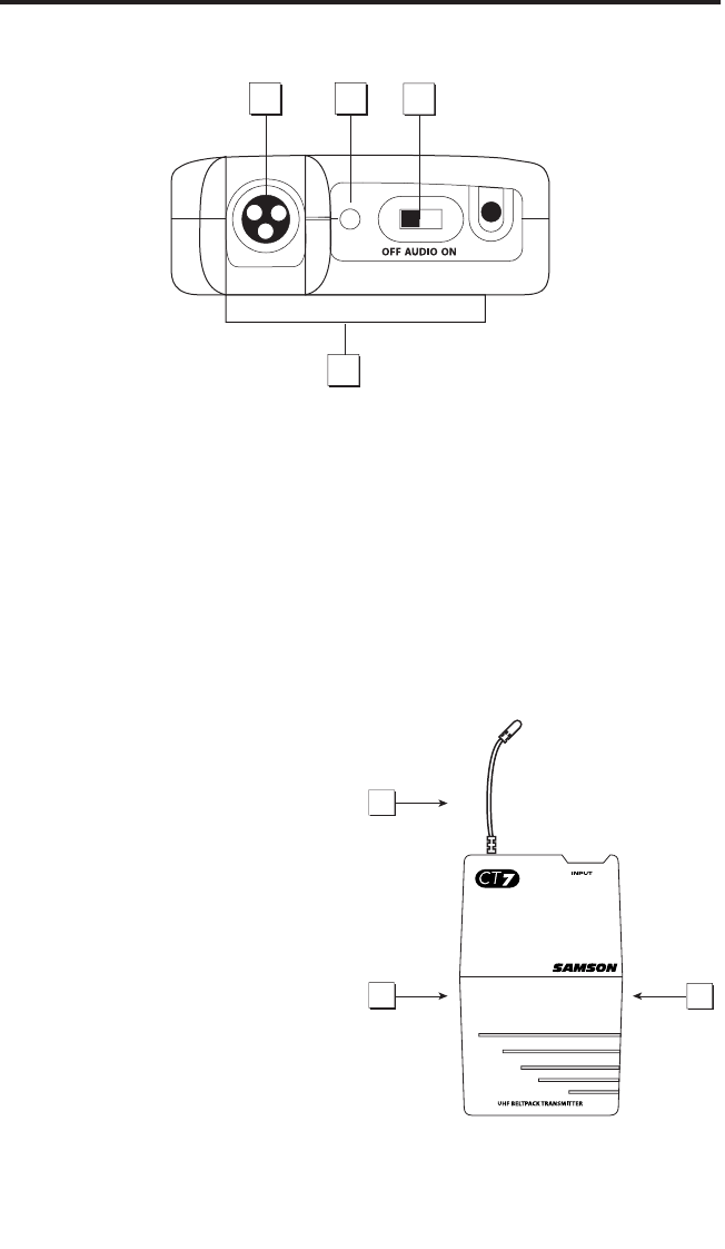
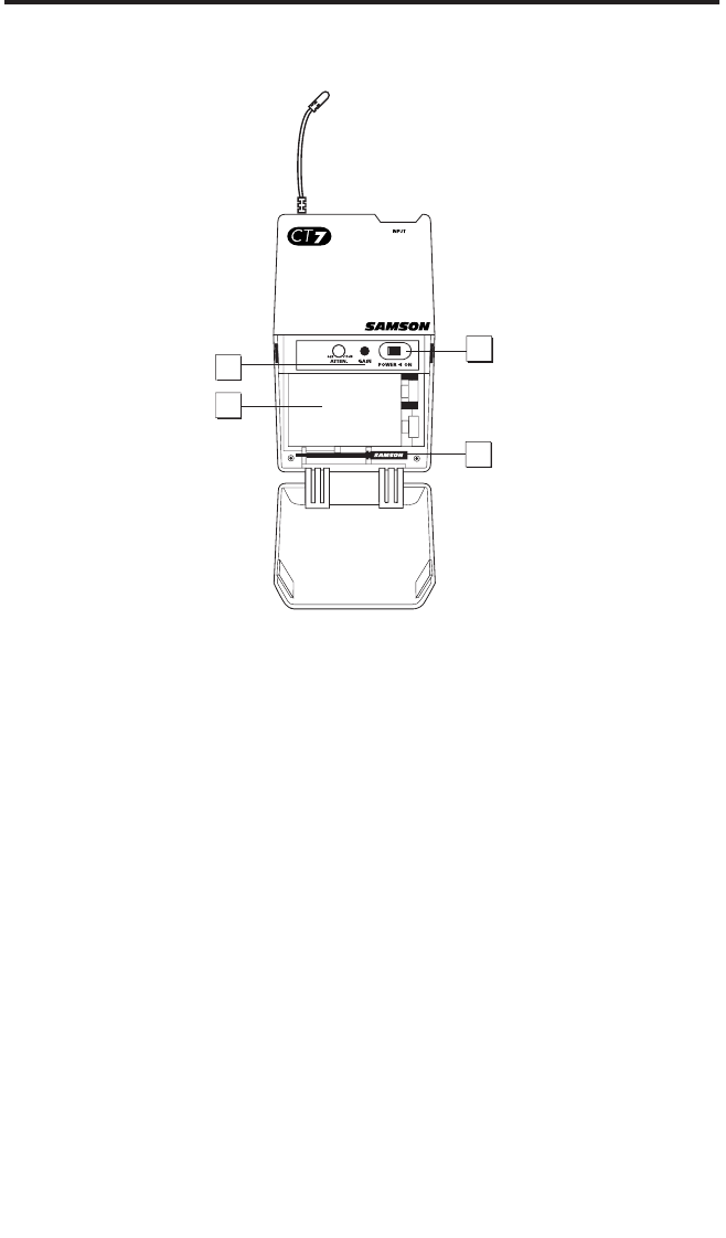
Guided Tour - CT7L /CT1G
1: Input connector
- The input device is connected here. The CT7 is supplied with either a lava-
lier or headset microphone or 1/4" jack cable (connected via a mini-XLR jack).
2: Power / Battery LED
- This LED flashes once when the CT7 is first turned on and lights
steadily red when there are less than 2 hours of battery power remaining, indicating that the
battery needs to be changed. In order to avoid compromising audio fidelity (or having the CT7
stop working completely), you should always replace the battery with a fresh one immediately
whenever this LED lights red.
3: Audio on-off switch
- When set to the “on” position, audio signal is transmitted. When set
to the “off” position, the audio signal is muted. Because the carrier signal remains during mut-
ing, no “pop” or “thud” will be heard. Note that turning this off does not turn off the transmitter
power—it is simply a way to temporarily mute the transmission of audio signal. If you don’t
plan on using the transmitter for extended periods, turn off the transmitter power by using the
power on-off switch (see #8 on the next page).
4: Belt clip
- Use this clip to fasten the CT7 to
a belt.
5: Battery cover release
- Push in both sides
of the battery cover and pull back to open the
CT7 battery cover.
6: Antenna
- This permanently attached trans-
mitter “stiff” antenna should be fully extended
for normal operations. See the “Setting Up and
Using the Concert Series
System” section on
page 8 in this manual for more information
about antenna positioning.
1
4
23
5
5
6
6
Guided Tour - CT7L / CT7G
7: Audio Input Level control (trimpot)
- This input sensitivity control has been factory preset to
provide optimum level for the particular lavalier, headset or for optimum instrument level, so we
recommend that this not be adjusted manually. If necessary, however, you can use the supplied
plastic screwdriver (see #10 below) to raise or lower the CT7 input level. See the “Setting Up and
Using the Concert Series System” section on page 8 in this manual for more information.
8: Battery holder
- Insert a standard 9-volt alkaline battery here, being sure to observe the
plus and minus polarity markings shown. We recommend the Duracell MN 1604 type battery.
Although rechargeable Ni-Cad batteries can be used, they do not supply adequate current for
more than four hours.
WARNING:
Do not insert the battery backwards; doing so can cause
severe damage to the CT7 and will void your warranty.
9: Power on-off switch*
- Use this to turn the CT7 on or off (to conserve battery power, be sure
to leave it off when not in use).
10: Plastic screwdriver
- Specially designed for use in adjusting the CT7 Audio Input Level
control (see #8 above) and/or CR77 Squelch control (see #7 on page 3). See the “Setting Up and
Using the Concert Series System” section on page 8 in this manual for more information.
* Be sure to mute the audio signal at your external mixer or amplifier before turning transmitter
power on or off, or an audible pop may result.
10
8
9
7
7
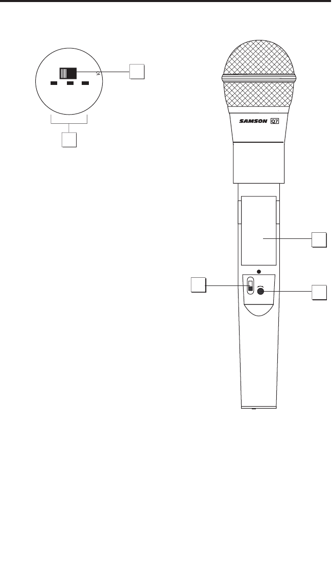
Guided Tour - HT7
1: Audio on-off switch
- When set to the “on” posi-
tion, audio signal is transmitted. When set to the “off”
position, the audio signal is muted. Because the car-
rier signal remains during muting, no “pop” or “thud”
will be heard. Note that turning this off does not
turn off the transmitter power—it is simply a way to
temporarily mute the transmission of audio signal. If
you don’t plan on using the transmitter for extended
periods, turn off the transmitter power by using the
power on-off switch (see #3 below).
2: Battery level meter
- This set of three multicolor
LEDs indicates relative battery power, indicating
whether the installed battery is at low (red), mid
(yellow) or high (green) strength. One of these will
light whenever the HT7 is powered on (see #3 below).
When the red “low” indicator lights, RF performance is
degraded and the battery needs to be replaced.
3: Power on-off switch*
- Use this to turn the HT7 on
or off (to conserve battery power, be sure to leave it
off when not in use).
4: Microphone Input Level control (trimpot)
- This
input sensitivity control has been factory preset to
provide optimum level for the particular microphone
capsule provided with your Concert 77 system and
so we recommend that this not be adjusted manually. If necessary, however, you can use the
supplied plastic screwdriver to raise or lower the input level. See the “Setting Up and Using the
Concert Series System” section on page 8 in this manual for more information.
5: Battery holder
- Insert a standard 9-volt alkaline battery here, being sure to observe the
plus and minus polarity markings shown. We recommend the Duracell MN 1604 type battery.
Although rechargeable Ni-Cad batteries can be used, they do not supply adequate current for
more than four hours.
WARNING:
Do not insert the battery backwards; doing so can cause
severe damage to the HT7 and will void your warranty.
* Be sure to mute the audio signal at your external mixer or amplifier before turning transmit-
ter power on or off, or an audible pop may result.
MIN MAX
LEVEL
POWER
ON
OFF
5
34
1
2

8
Setting Up and Using the
Concert Series System
Concert Series System
The basic procedure for setting up and using your Concert Series Wireless System takes only a
few minutes:
1. For the Concert Series system to work correctly, both the receiver and transmitter must be set
to the same channel. Remove all packing materials (save them in case of need for future service)
and check to make sure that the supplied CR77 receiver and CT7 or HT7 transmitter are set to
the same channel. If these channels do not match, contact your distributor or, if purchased in
the United States, Samson Technical Support at 1-800-372-6766.
2. Physically place the CR77 receiver where it will be used (the general rule of thumb is to main-
tain “line of sight” between the receiver and transmitter so that the person using or wearing
the transmitter can see the receiver). An optional rack-mount kit (available from your Samson
dealer) allows the CR77 to be mounted in a standard 19" rack if desired. Extend both “A” and “B”
antennas and place both in a vertical position.
3. Make sure the Power on-off switch in your CT7 belt-pack or HT7 handheld transmitter is set to
“Off.”
4a. If your system contains a CT7 belt-pack transmitter, push in both sides of the battery cover
and pull back to open the battery door, which is hinged and not intended to be removed from
the transmitter case. Please use care when opening this door as undue force will destroy the
hinge.
4b. If your system contains a HT7 handheld transmitter, unscrew the bottom section of the
microphone by turning it counterclockwise and then slide it off.
5. Place a fresh 9-volt alkaline battery in the transmitter battery holder, taking care to observe
the polarity markings. If you are using a CT7 belt-pack transmitter, gently replace the battery
door by swinging it up and pressing until it clicks. If you are using a HT7 handheld transmitter,
replace the bottom section of the microphone by sliding it on and then screwing it back on.
Whichever transmitter you are using, leave it off for the moment.
6. Make the physical cable connection between the CR77 output jack and the line or mic level
audio input of your amplifier or mixer. If you are using the balanced XLR jack (preferable, since
it will deliver an electromagnetically cleaner signal), be sure to set the CR77 rear panel Audio
Output Level switch correctly. If required, both the balanced and unbalanced outputs can be
used simultaneously. Leave your amplifier (and/or mixer) off at this time.
7. Turn the Volume knob on the CR77 completely counterclockwise. Using the strain relief,
connect the supplied AC adapter to the DC Input on the rear panel of the CR77, then plug the
adapter into any standard AC outlet. Press the front panel Power switch to turn on the CR77; the
red “Power” LED will light up, but all other front panel LEDs will remain unlit.
8. Turn on the power to the CT7 or HT7 transmitter (using its Power on-off switch); the green
“HIGH” Battery strength LED will light if the battery is sufficiently strong. At this point, either the
“A” or “B” green LED on the front panel of the CR77 will light (depending upon which antenna
is receiving the stronger signal). Also, one or more segments in the CR77 front panel RF Level
meter should light; the more are lit, the stronger the RF signal. If only one or two segments light
(indicating a relatively weak signal), try relocating the CR77 or changing the position of one or
both of its antennas. If all six segments light, the CR77 is receiving an optimally strong RF signal
and is placed and positioned correctly.
9. Now it’s time to set the audio levels. Turn on your connected amplifier and/or mixer but keep
its volume all the way down. Next, make sure that your transmitter is unmuted by setting its
Audio switch to “On.” Then set the Volume knob on the CR77 fully clockwise (to its “10” setting);

9
Setting Up and Using the
Concert Series System
this is unity gain. If you are using the HT7 transmitter or if you are using the CT7 transmitter with
a connected lavalier microphone or headset, speak or sing into the mic at a normal performance
level while slowly raising the volume of your amplifier/mixer until the desired level is reached. If
you are using the CT7 transmitter with a connected instrument, play the instrument at normal
performance level while slowly raising the volume of your amplifier/mixer until the desired level
is reached. If you are using a CT7 beltpack transmitter equipped with a lavalier microphone, note
that correct lavalier placement is critical to sound quality. We recommend that you place it as
shown in the illustration on the right—as close to your
mouth as possible but off to one side (to minimize nasal-
ity) and unobstructed by clothing. Bear in mind also that
omni microphones (mics which pick up signal from all
directions) are more prone to feedback problems than
unidirectional (cardioid or supercardioid) ones; in gen-
eral, you can avoid feedback by taking care not to use
any microphone directly in front of a PA speaker (if this
is unavoidable, try using an equalizer to attenuate those
high- or mid-range frequencies which are causing the
feedback “squealing”).
10. If you hear distortion at the desired volume level, first
check to see whether the yellow “Peak” LED on the CR77
is lit. If it is not, make sure that the gain structure of your
audio system is correctly set (consult the owners manual
of your mixer and/or amplifier for details). If the yellow
“Peak” LED is lit, do the following:
• If you are using a HT7 transmitter, use the supplied plastic screwdriver to turn its
Microphone Input Level control (trimpot) slowly counterclockwise (towards the “Min” posi-
tion) until the distortion disappears.
• If you are using a CT7 transmitter with connected lavalier microphone or headset, its Audio
Input Level control has been factory preset to provide optimum level for the particular
lavalier or headset model being used and so no adjustment should be necessary. Any dis-
tortion present should therefore simply be a matter of the microphone being too close to
the mouth; try moving it further away. If this does not solve the problem, use the supplied
plastic screwdriver to turn the Audio Input Level control (trimpot) on the CT7 slowly coun-
terclockwise until the distortion disappears.
• If you are using a CT7 transmitter with an instrument such as electric guitar or bass, lower
the output level of the instrument until the distortion disappears. Alternatively, you can use
the supplied plastic screwdriver to turn the Level control (trimpot) on the CT7 slowly coun-
terclockwise until the distortion disappears.
Note that, following this setup procedure, you can always lower the Volume knob of the CR77 in
order to attenuate the output signal if necessary.

11. Conversely, if you hear a weak, noisy signal at the desired volume level, again make
sure that the gain structure of your audio system is correctly set (consult the owners
manual of your mixer and/or amplifier for details) and that the Volume control of the CR77
is fully clockwise (at its “10” setting). If it is and the signal coming from the CR77 is still
weak and/or noisy, do the following:
• If you are using a HT7 transmitter, use the supplied plastic screwdriver to turn the
Level control (trimpot) on the transmitter slowly clockwise (towards the “Max” position)
until the signal reaches an acceptable level.
• If you are using a CT7 transmitter with connected lavalier microphone or headset,
its Level control has been factory preset to provide optimum level for the particular
lavalier or headset model being used and so no adjustment should be necessary.
Any weakness of signal should therefore simply be a matter of the microphone being
too far from the mouth; try moving it closer. If this does not solve the problem, use the
supplied plastic screwdriver to turn the Level control (trimpot) on the CT7 slowly clock-
wise until the signal reaches an acceptable level.
• If you are using a CT7 transmitter with an instrument such as electric guitar or bass,
raise the output level of the instrument until a good signal is achieved. Alternatively,
you can use the supplied plastic screwdriver to turn the Level control (trimpot) on the
CT7 slowly clockwise until the signal reaches an acceptable level.
12. Temporarily turn down the level of your mixer/amplifier system and turn off the power
to your transmitter, leaving the CR77 on. Then restore the previously set level of your
mixer/amplifier. With the transmitter off, the receiver output should be totally silent—if it
is, skip ahead to the next step. If it isnʼt (that is, if you hear some noise), you may need to
adjust the CR77 front panel Squelch control. When the Squelch control is at its minimum
setting, the Concert Series system always provides maximum range without dropout; how-
ever, depending upon the particular environment your system is used in, you may need
to reduce that range somewhat in order to eliminate band noise when the transmitter is
turned off. To do so, use the provided screwdriver to rotate the Squelch control completely
counterclockwise (to the “Min” position), then slowly turn it clockwise until the noise disap-
pears. If no noise is present at any position, leave it at its fully counterclockwise “Min”
position (so as to have the greatest overall range available).
13. When first setting up the Concert Series system in a new environment, itʼs always
a good idea to do a walkaround in order to make sure that coverage is provided for your
entire performance area. Accordingly, turn down the level of your audio system and turn
on both the transmitter and receiver. Then, with the transmitter unmuted, restore the
level of your audio system and while speaking, singing, or playing your instrument, walk
through the entire area that will need to be covered. As you do so, you will find that the
green “A” and “B” LEDs on the CR77 receiver occasionally switch on or off, always show-
ing you which antenna is receiving the stronger signal. Always try to minimize the distance
between transmitter and receiver as much as possible so that the strongest possible sig-
nal is received from all planned transmission points. In fixed installations such as A/V or
corporate conference rooms or for extended range applications (where the transmitter and
receiver are more than 150 feet apart), it may be desirable to angle the antennas different-
ly from their vertical position or to install the receiver in the same room as the transmitters
(and, if necessary, to extend the wiring to remote audio equipment).
If you have followed all the steps above and are experiencing difficulties, contact your
local distributor or, if purchased in the United States, call Samson Technical Support
(1-800-372-6766) between 9 AM and 5 PM EST.
10
Setting Up and Using the
Concert Series System
MANUFACTURER MODEL PIN 1 PIN 2 PIN 3
MANUFACTURER MODEL PIN 1 PIN 2 PIN 3
AUDIO TECHNICA AT831
YELLOW x 2
RED x 2 JUMP TO PIN 2
SHIELD
SHIELD
AUDIO TECHNICA AT831
SHIELD
AUDIO TECHNICA AT831
AUDIO TECHNICA ATM75
AUDIO TECHNICA ATM75
YELLOW x 2
RED x 2 JUMP TO PIN 2
SHIELD
SHIELD
AUDIO TECHNICA ATM75
SHIELD
AUDIO TECHNICA ATM75
AUDIO TECHNICA ATM75
SHIELD
AUDIO TECHNICA ATM75
AUDIO TECHNICA ATPRO8HE
AUDIO TECHNICA ATPRO8HE
YELLOW x 2
N/C RED x 2
SHIELD
SHIELD
AUDIO TECHNICA ATPRO8HE
SHIELD
AUDIO TECHNICA ATPRO8HE
AUDIO TECHNICA ATPRO8HE
SHIELD
AUDIO TECHNICA ATPRO8HE
AUDIO TECHNICA MT350
AUDIO TECHNICA MT350
SHIELD WHITE JUMP TO PIN 2
SONY ECM44
SONY ECM44
SHIELD
RED JUMP TO PIN 2
WHITE
WHITE
SONY ECM44
WHITE
SONY ECM44
SONY ECM44
WHITE
SONY ECM44
SONY ECM40
SHIELD WHITE JUMP TO PIN 2
COUNTRYMAN ISOMAX
COUNTRYMAN ISOMAX
SHIELD WHITE JUMP TO PIN 2
GUITAR
GUITAR
SHIELD N/C AUDIO
PIN INFORMATION
PIN INFORMATION
SWITCHCRAFT
GROUND +Vdc AUDIO
TA3F
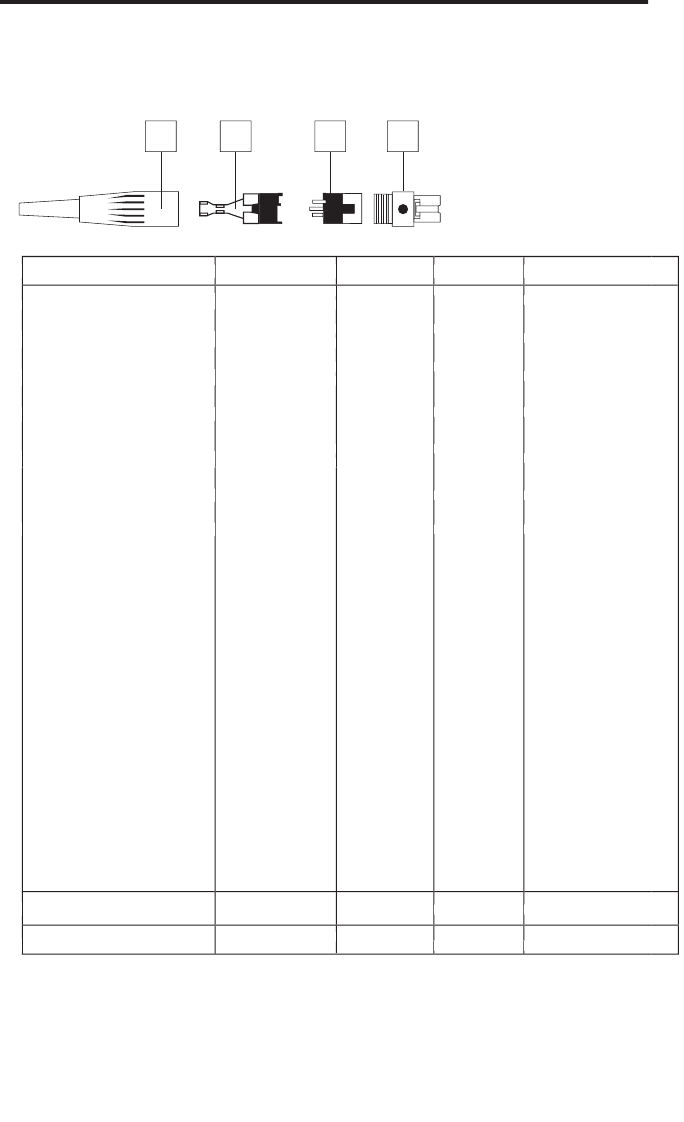
Procedure for wiring CT7L connector:
Unscrew rubber boot 1 and pass wire
Unscrew rubber boot 1 and pass wire
Unscrew rubber boot 1 and pass wire
Unscrew rubber boot 1 and pass wire
through 1 and 2. Solder wire to 3 after removing from 4 (use chart above).
Reinsert 3 to 4 with attached wire (3 is keyed to fit 4). Plug 2 into 3 again (2 is
Reinsert 3 to 4 with attached wire (3 is keyed to fit 4). Plug 2 into 3 again (2 is
Reinsert 3 to 4 with attached wire (3 is keyed to fit 4). Plug 2 into 3 again (2 is
keyed to 3) and crimp wire. Resc
Appendix A: CT1L Multipin
Wiring Guide and Chart
SWITCHCRAFT TA3F
1 2 3 4
MANUFACTURER MODEL PIN 1 PIN 2 PIN 3
AUDIO TECHNICA AT831
SHIELD
AUDIO TECHNICA AT831
SHIELD
AUDIO TECHNICA AT831
AUDIO TECHNICA ATM75
SHIELD
AUDIO TECHNICA ATM75
SHIELD
AUDIO TECHNICA ATM75
AUDIO TECHNICA ATPRO8HE
SHIELD
AUDIO TECHNICA ATPRO8HE
SHIELD
AUDIO TECHNICA ATPRO8HE
AUDIO TECHNICA MT350
SONY ECM44
WHITE
SONY ECM44
WHITE
SONY ECM44
SONY ECM40
COUNTRYMAN ISOMAX
MANUFACTURER MODEL PIN 1 PIN 2 PIN 3
YELLOW x 2
SHIELD
YELLOW x 2
SHIELD
YELLOW x 2
SHIELD
SHIELD
WHITE
SWITCHCRAFT
MANUFACTURER MODEL PIN 1 PIN 2 PIN 3
YELLOW x 2
YELLOW x 2
YELLOW x 2
SHIELD WHITE JUMP TO PIN 2
SHIELD
SHIELD WHITE JUMP TO PIN 2
SHIELD WHITE JUMP TO PIN 2
SHIELD N/C AUDIO
GROUND +Vdc AUDIO
MANUFACTURER MODEL PIN 1 PIN 2 PIN 3
RED x 2 JUMP TO PIN 2
RED x 2 JUMP TO PIN 2
N/C RED x 2
SHIELD WHITE JUMP TO PIN 2
RED JUMP TO PIN 2
SHIELD WHITE JUMP TO PIN 2
SHIELD WHITE JUMP TO PIN 2
SHIELD N/C AUDIO
GROUND +Vdc AUDIO
12

12
Specifications
System Specifications:
Channels 6
Frequency Type F3
Modulation Type FM
Noise Reduction Type Compander/Expander
Distance 300 feet
Transmitter (HT7, CT7):
Oscillation Type Direct PLL
Pre-emphasis 50
μ
sec
Antenna
HT7 Integral Antenna
CT7 1/4 Wave Length Wire (Pig Tail)
Input (CT7) TB3M Switchcraft Connector
Maximum Input Level 3 V p-p
Battery Duracell MN1604 9-volt alkaline
Operating Temperature -20° C / 55° C
Switches / Controls Power ON/OFF, Audio ON/OFF
HT7 Mic Level Volume
CT7 Audio Level
Display (LED) Battery Low/Mid/High (corresponds to <5.3 V / 5.3 - 7 V / >7V)
Operating Voltage 9 Volts +20% / -40%
Current Consumption 47 mA
RF Power 10 mW
Frequency Stability ±20 kHz
Spurious Ratio 2.5 nW
Deviation 20 kHz (16.5 kHz - 23.5 kHz)
T.H.D. (Overall) 0.5% (3% max) (@AF 1 kHz, RF 46 dBu)
AF Frequency Response 50 Hz - 15 kHz (±3 dB overall)
Battery life 12 hours
Receiver (CR77):
Oscillation Type PLL
De-emphasis 50
μ
sec
IF Frequency 10.7 MHz
Antenna 1/4 Wavelength Rod
In/Out DC Inlet, Balanced Output, Unbalanced Output
Display (LED) Receiver A/B (Green), Power On (Red), Peak (Yellow), RF Level (5 pc)
Level Control Audio Level Volume, Mute Level Control
Operating Temperature 0° C / 50° C
Operating Voltage 12 Volts ±10%
Current Consumption 160 mA (at all LED lights)
Receiving Frequency Range 801 - 805 MHz
Sensitivity 18 dB
μ
(@ THD 2%)
Squelch Sensitivity 0 - 40 dB
μ
(Adjustable)
Selectivity ±150 kHz (AF Out Ratio -60 dB)
T.H.D. (Overall) 1% Max (@AF 1 kHz, RF 46 dBu)
S/N Ratio (Overall) 90 dB (w/IHF-A Filter)
Residual Noise 90 dBv (w/IHF-A Filter)
Band Mute ±40 kHz / ±100 kHz (RF IN: 46 dBu EMF)
AF Frequency Response 50 Hz - 15 kHz (±3 dB overall)
Audio Output Level - Unbalanced 0 dBv
Audio Output Level - Balanced -20 dBm (Line), -40 dBm (Mic)
Audio Output Impedance - Unbalanced 5 k Ohms
Audio Output Impedance - Balanced 600 Ohms
Specifications subject to change.


Samson Technologies Corp.
575 Underhill Blvd.
P.O. Box 9031
Syosset, NY 11791-9031
Phone: 1-800-3-SAMSON (1-800-372-6766)
Fax: 516-364-3888
www.samsontech.com