Selex Sistemi Integrati DMEH2 AVIATION SERVICES DME TRANSMITTER User Manual USERS MANUAL 1
Selex Sistemi Integrati Inc. AVIATION SERVICES DME TRANSMITTER USERS MANUAL 1
Contents
- 1. USERS MANUAL 1
- 2. USERS MANUAL 2
USERS MANUAL 1

1.INSTALLATION, INTEGRATION AND CHECKOUT
1.1 Introduction
This section contains installation information for the independently located DME. If the DME is to be
collocated with VOR or ILS refer to the basic instructions in this section and to the installation instructions
for the VOR or ILS equipment. With respect to general requirements, a good VOR or ILS site will satisfy
the DME requirements as well. System performance must be verified by flight inspection. Figure 1-1
shows a typical DME site.
NOTE
After flight inspections and prior to use by pilots, it is mandatory that
the monitor be left in control of the facility and not in bypass.
1.2 Site Information
1.2.1 Site Selection
The signal radiated from the DME is affected by obstructions and terrain in the immediate vicinity of the
antenna and by obstructions and terrain within the service range of the station. An ideal site would be the
highest ground in the vicinity with level terrain, cleared of all objects for a radius of at least 3000 feet (915
meters), and with no obstructions extending above the horizontal plane of the antenna within the service
range of the station. In most localities, it is not possible to satisfy the ideal site requirements. Every effort
must be made to obtain the best site available. Although no absolute minimum requirements can be stated,
a site is normally acceptable if it meets the recommendations contained in the following paragraphs.
1.2.1.1 Terrain Features
The terrain should be level within a radius of 200 feet (61 meters). In a radius between 200 and 1000 feet
(61 and 305 meters), a downward slope is acceptable if (1) the rate of descent is not more than 4 feet in 100
feet (1.22 meters in 30.5 meters) and (2) contour lines are generally circular around the site. Beyond a
radius of 1000 feet (305 meters), terrain should be below the horizontal plane of the antenna.
1.2.1.2 Obstructions
There should be no structures within 750 feet (229 meters) of the antenna. Metallic structures should not
subtend vertical angles greater than 1.2 degrees as measured from the antenna. Wooden structures with
negligible metal content should not subtend vertical angles greater than 2.5 degrees as measured from the
antenna. Structures having considerable length (such as aircraft hangers or administration buildings)
should be situated lengthwise on a radial from the antenna. Single trees less than 35 feet (11 meters) high
may be tolerated beyond 750 feet. No group of trees or groves may be within 1000 feet. No overhead
power or control lines are permissible within 750 feet of the antenna.
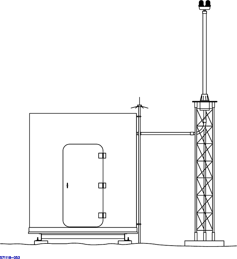
Figure 1-1 Typical DME Site

1.2.2 Shelter Requirements
The shelter location depends primarily on the maximum cable run allowed and on the desired location for
the DME antenna. An RF transmission line of 2" foamflex cable (with Type N connectors at each end),
one cable for the monitor antenna made up of 1/4" foamflex (with a Type N connector at one end and a
TNC male connector at the opposite end), and one AC cable for the OB Lite may be supplied with the
DME equipment. These cables are 35 feet long. When the requirements exceed 35 feet, company
engineering personnel can provide the necessary planning to determine the requirements.
The DME ground equipment is designed to operate continuously and unattended, but space must be
allocated for maintenance personnel and their equipment.
1.3 Unpacking and Repacking
The DME electronic subsystem is shipped unassembled. Only general precautions can be given because
the crating and unpacking depends upon destination and what optional equipment is included. Most items
are packed separately in individual containers; these are then grouped for crating. Each crate contains a
packing list which details what equipment is enclosed in the crate. Unpack the equipment and visually
inspect each item for accuracy and damage, but DO NOT REMOVE any ESD protective wrapping.
Report any damage immediately. After inspection, repack each item to prevent damage. During
installation, unpack items as they are needed.
1.3.1 Environmental Considerations
The environmental conditions must not exceed those listed in the Specifications of Table 1-1 Error!
Reference source not found..
1.4 Input Power Requirement Summary
The requirements for input power must not exceed those listed in the Specification of Table 1-1 Error!
Reference source not found..
1.5 Installation Procedures
1.5.1 Installation Tools and Test Equipment
Refer to Error! Reference source not found.for a list of test equipment and Table 1-1 for a list of special
tools required for installation.
Table 1-1 Special Tools Required for Installation
Description
Tube Cutter
File
Knife
2-1/4" Hole Saw
Assorted Screw Drivers and Wrenches
Thread Tape

1.5.2 Installation Kits
Refer to Table 1-2 for all component or modification kits required to install the DME station. Some kits
listed are optional equipment. Kits ending with “X” have many different varieties and will vary depending
on the site specific requirements. In all necessary cases installation drawings for each kit are provided with
the kit hardware.
Table 1-2 Component or Modification Kits Required to Install the DME
Part Number Description
470085-000X DME Tower Antenna Kit
470561-0001 DME Unidirectional GS Tower Mount Antenna Kit
470628-000X DME Battery Backup Kit, 35AHr
470622-0001 DME Accessory Kit
470627-0001 DME AC Power/Installation Kit
470291-000X DME OB Light Kit
470623-0001 Environmental Sensors Kit
470360-000X PMDT Kit
Table 1-3 Additional kits required to Install Shelter and Tower Grounding Systems
Part Number Description
470252-0002 Civil Install Kit, 45G Rohn Tower
470225-0001 Civil Install Kit, Shelter
470557-0001 Shelter Internal Grounding Kit
1.5.3 Shelter Foundation Installation
For shelters not supplied by SELEX Sistemi Integrati Inc., the manufacturer of the shelter will supply
drawings for the site engineer.
1.5.4 Shelter Installation
a. Use a crane and four nylon slings (20 feet long) to position the equipment shelter on the four concrete
piers.
b. Attach the shelter to the pier anchor bolts using appropriate hardware.
1.5.5 Tower Foundation and Tower Installation
A triangular steel tower is available for use as a support for the DME antenna. Figure 1-2 shows the
installation details for this tower. Figure 1-3 illustrates the triangular tower adapter plate required to mount
the antenna to the DME tower.
1.5.6 Shelter and Tower Installation Grounding
a. Install ground rods and ground wire as detailed in Figure 1-2 and Figure 1-4.
b. Install the 470557 Shelter Internal Grounding Kit per the drawing provided with the kit.
c. Verify the shelter grounding plate, AC wiring, lightning protection, RF tower, and telephone
equipment all share a common grounding potential. The impedance between any of these items should
be below 10Ω.
1.5.7 Air Conditioner Installation
If a wall mounted air conditioner is supplied, install the air conditioner in the wall opening and secure it in
place using bracket supplied. Apply silicon seal around air conditioner and wall opening to maintain a
weather tight seal.

Figure 1-2 Typical DME Tower Installation Diagram
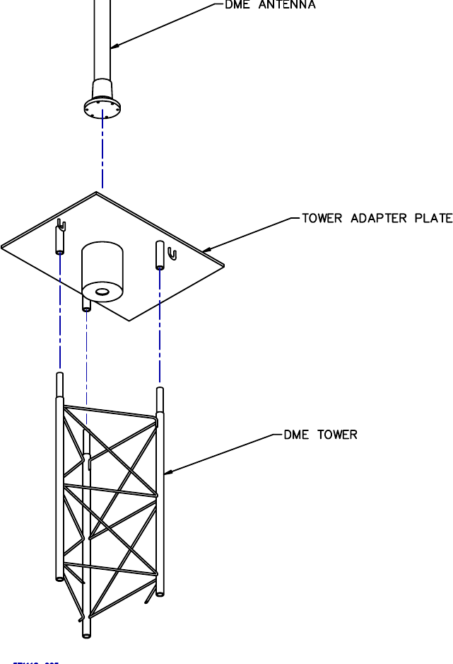
Figure 1-3 Triangular Tower Adapter Plate

Figure 1-4 Typical DME Shelter and Tower Grounding Diagram
1.5.8 DME Cabinet Installation
a. Unpack the DME 19” rack system and stand upright inside the equipment shelter.
b. The rack can be located on an outside wall or in the center of the room; however the ventilation
louvers located on the left side of the cabinet must not be obstructed.
c. To level the rack use the adjustable feet then lock the feet positions using the jam nuts.
d. If desired the front and rear doors can easily be removed by sliding up the three hinge pins on the left
inside edge of each door. If the doors are removed be sure to replace them after installation.
e. Use #6 grounding wire provided in the AC Power/Installation Kit (Figure Error! Reference source
not found.) to connect from the DME grounding bus bar to the shelter grounding plate using the
shortest path possible.
NOTE: Do not install any modules in the rack until it is properly grounded.
1.5.9 Battery Backup Assembly Installation
a. Insure DME system AC and DC circuit breakers are in the OFF position.
b. Construct battery backup unit as detailed in Figure Error! Reference source not found. or per the
drawing provided with supplied battery backup kit.
c. Install the four twelve-volt batteries and connect batteries in series.

d. Install battery backup wiring between the DME transmitter cabinet and the battery backup assembly.
The battery ground lead should connect to the grounding bus bar and the battery hot wire (+48V)
should connect to TX1 DC breaker located on the 1A26 Status Panel Assembly.
e. When supplied with two battery kits then connect the hot wire (+48V) from the second battery set to
the TX2 DC breaker; otherwise install the jumper wire between TX2 DC breaker and TX1 DC breaker
as provided in the battery kit.
f. Install safety cover(s) over batteries or lid(s) on battery backup box.
CAUTION: Shorting the battery leads can cause a fire or explosion.
1.5.10 Primary AC Power Installation
AC wiring for the DME will require a separate circuit breaker for the DME system and DME obstruction
lights. The convenience outlet located on the front of the 1A26 Status Panel is powered from the
obstruction light breaker.
a. Insure DME system AC and DC circuit breakers are in the OFF position
b. Insure that shelter DME system circuit breaker is in the OFF position.
c. Connect primary AC power to DME as detailed in Figure Error! Reference source not found..
1.5.11 Shelter to Tower Conduit Connections
a. Using a 2-1/4" hole saw, cut a hole in the wall between the DME transmitters and the antenna tower at
a height above the top of the DME transmitter cabinet.
b. Refer to Figure Error! Reference source not found.. Slide 2" x 5" threaded conduit into hole. Install
reducing washer and 2" locknut on each end of threaded conduit. Tighten locknut.
c. Install protective bushing on exposed threaded conduit threads of interior shelter wall. Install 2" PVC
female adapter on threaded conduit of outer shelter wall.
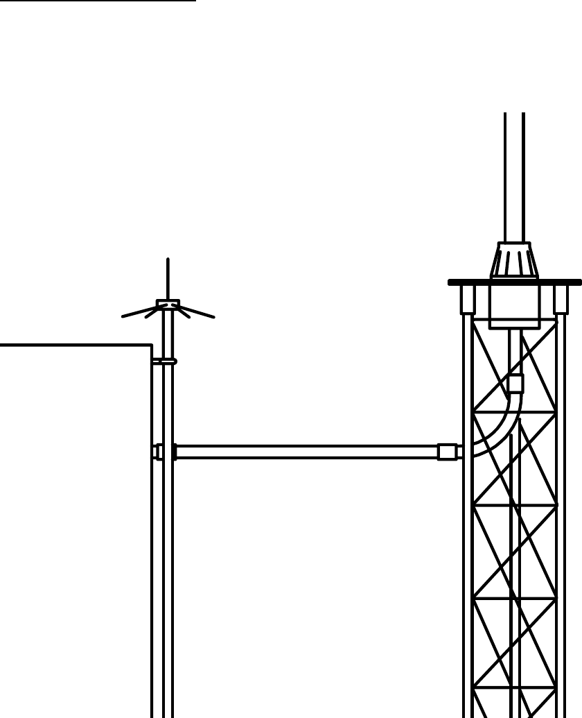
d. Refer to Figure 1-7. Cut 2" PVC appropriate length to center of tower directly under antenna.
e. Install 2" PVC hole adapter in bottom of triangular tower adapter plate. Install reducing washer and 2"
locknut onto hole adapter. Install protective bushing over exposed threads.
f. Cut 2" PVC appropriate length to extend from triangular tower adapter plate to 2" PVC from shelter.
Insure that 2" PVC from triangular tower adapter plate is cut so that PVC from shelter slopes slightly
downward as it runs to tower.
g. Install 2", 90 degree PVC connector and 2" conduit adapters between the two pieces of 2" PVC and
insure that all pieces fit. Drill a 1/8" hole in the bottom of 2" 90 degree PVC connector. This will
allow any water seepage to drain. Pre-fit all pieces to insure proper mating.
1.5.12 Obstruction Light Installation and Wiring
The obstruction light assembly is shipped separately from the DME antenna and it is necessary to attach the
obstruction light to the top of the DME antenna; and the wiring that extends from the antenna must be
connected to the bulb sockets. Figure 1-8 shows the assembly details.
NOTE
The mounting hole on the top of the DME antenna is threaded for a
3/4" pipe thread. There are two versions of obstruction light assemblies
available: one is threaded for a 3/4" pipe thread; the other is threaded
for a 1" pipe thread. For the 3/4" pipe version, a 1" to 3/4" reducer and
a 3/4" by 1-1/2" nipple stainless steel combination should be used.
a. Remove lens and bulbs.
b. Remove the hole cap at the top of the DME antenna and fish out the AC wires using stiff wire bent into
a hook.
c. Route the three wire AC cable from the DME antenna through the required pipe adapters and into the
bulb sockets.
d. Thread the obstruction light assembly into the antenna. Use thread tape on all pipe threads to insure a
water tight fit.
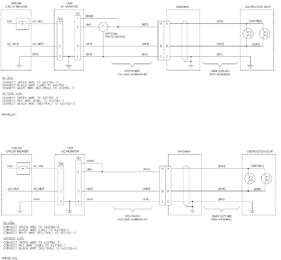
e. Connect the three AC wires from the antenna to the bulb sockets, as shown in Figure 1-5 or Figure 1-6.
f. Install the lighting rod to the obstruction light nipple as detailed in Figure Error! Reference source
not found..
g. Verify the obstruction light bulbs match the site AC voltage rating then install the bulbs and lens.
h. After installing antenna to tower, connect remaining obstruction light power wires to DME cabinet and
shelter circuit breaker box as shown in Figure 1-5 or Figure 1-6. Note that the 070219-0001 cable is
located in the Antenna Kit (Figure Error! Reference source not found.).
Figure 1-5 DME Obstruction Light Interconnect Diagram with Photo Sensor
Figure 1-6 DME Obstruction Light Interconnect Diagram without Photo Sensor
1.5.13 DME Antenna Installation
a. Use a crane and nylon slings to lift the DME antenna to the top of tower.
b. Install DME antenna on triangular tower adapter plate as shown in Figure Error! Reference source
not found.. Orientation of the obstruction bulbs and lightning rod is not important.
c. Secure antenna with appropriate hardware provided in the DME antenna kit.
Figure 1-7 Typical Shelter to Tower Conduit Installation
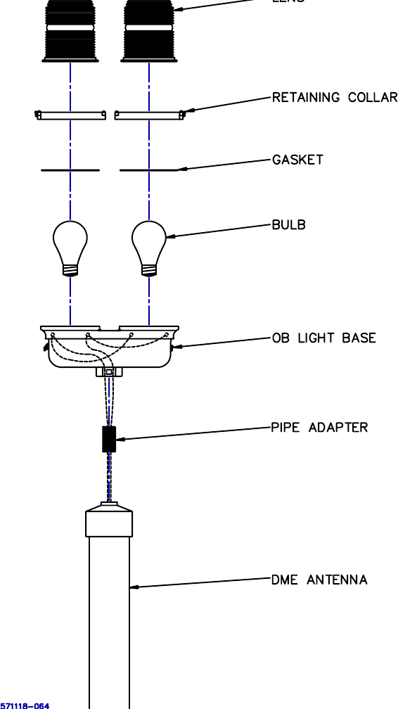
Figure 1-8 Obstruction Light Installation Diagram

1.5.14 DME Transmitter to Antenna Interconnect
a. Refer to Figure 1-7. Route ½” Heliax RF feedcable through conduit and connect to antenna connector
J1 (RF INPUT).
b. Route ¼” Heliax antenna monitor cable through conduit and connect to antenna connector J2 (RF
MONITOR OUTPUT). Note that in most installations the J3 RF MONITOR OUTPUT port can be
used instead of J2 however J2 is preferred.
c. Route obstruction light power cable through conduit and to antenna connector J4 (OBSTN LT
INPUT).
d. Connect ½” Heliax RF feedcable to DME transmitter connector 1J1 (RF OUT).
e. Connect ¼” Heliax antenna monitor cable to DME transmitter connector 1J2 (ANT MON1).
f. Place obstruction light circuit breaker to the ON position. Verify obstruction lights illuminate.
g. Using PVC cement, glue 2" PVC conduit connections previously installed.
1.5.15 Connecting VOR or ILS Keyer Wiring
a. Verify that the primary AC power (located in the shelter main circuit breaker box), VOR equipment
and DME equipment circuit breakers are in the OFF position.
b. Using the two-conductor electrical cable and forked terminal lugs provided in the AC
Power/Installation kit (Figure Error! Reference source not found.), connect KEY_OUT+ and
KEY_OUT- signals from the 1A19 Interface CCA located in rear of the DME cabinet to the
appropriate location as identified in Table 1-4.
Note after equipment startup refer to section Error! Reference source not found. Error! Reference
source not found. to configure external keying.
Table 1-4 External Keying Connection Locations
SELEX Navaid
KEY_OUT+ (1A19TB2-14)
Destination
KEY_OUT- (1A19TB2-15)
Destination
1150 VOR TB10-5 TB10-6
2100 Localizer 1A18TB4-1 1A18TB4-2
2110 Glideslope 1A18TB4-1 1A18TB4-2
1.5.16 RCSU and RMM Connections
a. If the DME is provided with a 2238 RCSU then connect the copper wires from the RCSU to the
1A19TB2-1 and 1A19TB2-2 locations on the Interface CCA for a Dedicated Modem connection type.
For a RF Modem/Fiber connection type, the RS232 connection should be made to the 1A19J5 DB9
connector. DIP switch S2-1 located on the 1A8A1 Low Power Backplane CCA should be set to match
the Connection Type as well.
b. If a telephone line is available for remote maintenance monitoring (RMM), connect the tip and ring
wires from the telephone interface box to the 1A19 Interface CCA locations TB2-3 and TB2-4.
Polarity is not important. DIP switch S2-2 located on the 1A8A1 Low Power Backplane CCA should
be set to “DIAL-UP” when using this internal dial-up modem. Use the two-conductor electrical cable
provided in the AC Power/Installation kit (Figure Error! Reference source not found.) for this
connection.
c. If the DME’s internal dial-up modem is unable to comply with local telephone requirements then
connect the telephone line to an external modem and connect the external modem serial port to the
1A19 Interface CCA J6 connector. DIP switch S2-2 located on the 1A8A1 Low Power Backplane
CCA should be set to “~EXTERNAL” when using an external dial-up modem. Reset the DME station
after changing the S2-2 switch.
d. DIP switch S1-6 located on the 1A8A1 Low Power Backplane CCA controls whether the DME station
will allow remote configuration of transmitter and monitor parameters. When set to “RMT

ALLOWED” a remote user logged into Security Level 3 can put the DME station in Local Mode from
the PMDT and change all parameters as if connected directly to the cabinet in the shelter. When set to
“~NOT ALLOWED” the system can not be put in Local Mode from the PMDT and remote parameter
changes are blocked throughout the software.
1.6 Inspection
Prior to energizing the equipment, a visual inspection is made to eliminate circumstances that could cause
power-up failures.
a. Visually inspect wire, RF coaxial cables and connectors for corrosion, loose connectors and
improperly assembled connectors.
b. Insure all terminal boards are free of foreign objects such as pieces of wire or other objects that could
cause electrical shorts within the equipment. Remove foreign objects as necessary.
c. Inspect the battery backup units to ensure that all terminals and connectors are tight and that there are
no metal shavings or other objects that could cause damage to the equipment.
1.7 Initial Start-up and Preliminary Testing
The following paragraphs detail the step-by-step procedures for initial start-up and preliminary testing of
the DME.
1.7.1 Input Voltage Checks
After the AC and DC power has been connected to the DME transmitter. It is necessary to check the input
power to insure the proper voltage is applied to the system.
a. Assure that the DME AC and DC circuit breakers to the OFF position.
b. Set the shelter primary AC power circuit breakers to the ON position.
c. Using an AC voltmeter check voltage across the AC Monitor 1A22TB3-1 (LINE) to 1A22TB3-2
(NEUTRAL) terminals. Insure the voltage meets the range specified in section Table 1-1 Error!
Reference source not found..
d. Turn on the DME DC circuit breaker while leaving the AC circuit breakers OFF.
e. Using a DC voltmeter check voltage across 1A20 BCPS1 E7 (BATT_POS) to E9 (GND). Insure the
voltage is 42 to 50Vdc.
f. For dual equipment check voltage across 1A21 BCPS2 E7 (BATT_POS) to E9 (GND). Insure the
voltage is 42 to 50Vdc.
g. Turn DC circuit breakers to the OFF position.
1.7.2 Installing Modules in Transmitter Cabinet
Since the DME transmitter cabinet is shipped separately from its electronic modules, it will be necessary to
install them into the transmitter equipment cabinet. Insure AC and DC circuit breakers are set to the OFF
position.
CAUTION
Many of the modules used in the DME transmitter contain
Electrostatic Discharge (ESD) sensitive components. ALWAYS
wear protective wrist strap when installing modules or CCAs.
Before modules are installed into transmitter cabinet, check
modules or CCAs for cracked or broken connectors, bent pins, and
loose hardware. Report any damage immediately.
1.7.3 Turn on Procedure
a. Verify all assemblies are properly installed and are fully seated.
b. Turn AC and DC circuit breakers to the ON position.
c. Verify the PWR_OK LEDs are lit on all card cage modules.
d. Verify the CPU_OK LEDs are lit on the RTC, Monitor, and RMS assemblies.

1.7.4 PMDT Hookup and Setup
a. Unpack the PMDT laptop computer and follow the manufacturer’s installation instructions to power-
up the computer, create a user account, and logon to Windows™ as an administrator.
b. Insert the 978178-XXXX PMDT CD-ROM into the laptop computer.
c. Select Start >> Run then type D:\Setup.exe to start the PMDT installation. Note if installation
does not start then use the correct drive letter associated with the CD-ROM drive.
d. Follow the default prompts for PMDT installation.
e. In order for the PMDT controls to be properly displayed change the DPI Setting to “Normal (96 DPI)”
in Windows on the Display Properties >> Settings >> Advanced >> General tab. Note that Display
Properties can be accessed by right-clicking on the Windows background then selecting Properties.
f. At the DME assure the AC and DC breakers are in the ON position.
g. Plug the USB cord between the laptop computer and 1A13J1 (PMDT USB) located on the RMS CCA.
h. Windows should detect the USB device and start installing a driver. If prompted for the USB driver
files they are installed in the PMDT directory at C:\Program Files\SELEX-SI\PMDT\FTDI USB
Driver.
i. Start the PMDT application by double-clicking on the desktop icon named PMDT.
j. Select System >> PMDT Setup.
k. In the Navaid Direct COM Port control pick the COM port that contains “USB Serial Port” in the
description.
l. On the PMDT configuration screen, setup other options such as Language and Print Screen mode then
select OK to save the changes.
m. Refer to section Error! Reference source not found. Error! Reference source not found. to connect
to the DME equipment at Security Level 3.
1.7.5 Site Adjustments and Configurations
a. Press the LOCAL CONTROL button on the 1A1 LCU to put the DME into Local Mode.
b. At the LCU bypass the Integral monitor and put Transmitter 1 on antenna.
c. If the VSWR reading on the Monitors >> Data >> Integral screen is in alarm then shut down the DME
and troubleshoot the RF feedcable to antenna connection before continuing. VSWR alerts detected by
each power amplifier can also be found on the Transmitters >> Data >> Transmitter Data screen that
indicate a faulty RF load.
d. On the Monitors >> Data >> Integral screen note the ERP (Effective Radiated Power) value for each
monitor.
e. On the Monitors >> Configuration >> Integral screen change the Monitor 1 Replay Attenuation setting
until the Monitor 1 EPR is 0 ± 1dB.
f. For dual monitor equipment change the Monitor 2 Replay Attenuation setting until the Monitor 2 EPR
is 0 ± 1dB.
g. On the RMS >> Configuration >> Station screen verify the channel number and type (X or Y) match
the site requirements and frequency paring requirements as identified in Table 1-5. If corrections are
needed then refer to section Error! Reference source not found. Error! Reference source not
found..
h. While on the RMS >> Configuration >> Station screen type a Station Identifier message that will be
used to uniquely identify the station when performing local or remote maintenance. It is suggested that
the site name and runway identifier be included.
i. If the DME is provided with a 2238 RCSU then on the RMS >> Configuration >> General screen
check the RCSU Present box and configure the Connection Type and Interlock Control to match the
installation requirements.
j. Set the Primary Ident Code to the assigned station identifier as detailed in section Error! Reference
source not found. Error! Reference source not found.. Also select the keying source and other
keying options while on that screen.
k. Select RMS >> Config Backup to save changes to the DME configuration.
l. If using a wattmeter with removable elements for site maintenance then perform the procedure in
section Error! Reference source not found. Error! Reference source not found..

Table 1-5 DME Channel Frequency Allocation
ILS/VOR Frequency Monitor Interrogator Transmitter Reply Receiver LO
DME
Channel
LOC
(MHz)
GS
(MHz)
VOR
(MHz)
Freq
(MHz)
Pulse Code
µs
Freq
(MHz)
Pulse Code
µs
Freq
(MHz)
1X - - - 1025 12 962 12 900
1Y - - - 1025 36 1088 30 900
2X - - - 1026 12 963 12 901
2Y - - - 1026 36 1089 30 901
3X - - - 1027 12 964 12 902
3Y - - - 1027 36 1090 30 902
4X - - - 1028 12 965 12 903
4Y - - - 1028 36 1091 30 903
5X - - - 1029 12 966 12 904
5Y - - - 1029 36 1092 30 904
6X - - - 1030 12 967 12 905
6Y - - - 1030 36 1093 30 905
7X - - - 1031 12 968 12 906
7Y - - - 1031 36 1094 30 906
8X - - - 1032 12 969 12 907
8Y - - - 1032 36 1095 30 907
9X - - - 1033 12 970 12 908
9Y - - - 1033 36 1096 30 908
10X - - - 1034 12 971 12 909
10Y - - - 1034 36 1097 30 909
11X - - - 1035 12 972 12 910
11Y - - - 1035 36 1098 30 910
12X - - - 1036 12 973 12 911
12Y - - - 1036 36 1099 30 911
13X - - - 1037 12 974 12 912
13Y - - - 1037 36 1100 30 912
14X - - - 1038 12 975 12 913
14Y - - - 1038 36 1101 30 913
15X - - - 1039 12 976 12 914
15Y - - - 1039 36 1102 30 914
16X - - - 1040 12 977 12 915
16Y - - - 1040 36 1103 30 915
17X - - 108.0 1041 12 978 12 916
17Y - - 108.05 1041 36 1104 30 916

Table 1-5 DME Channel Frequency Allocation
ILS/VOR Frequency Monitor Interrogator Transmitter Reply Receiver LO
DME
Channel
LOC
(MHz)
GS
(MHz)
VOR
(MHz)
Freq
(MHz)
Pulse Code
µs
Freq
(MHz)
Pulse Code
µs
Freq
(MHz)
18X 108.1 334.7 - 1042 12 979 12 917
18Y 108.15 334.55 - 1042 36 1105 30 917
19X - - 108.2 1043 12 980 12 918
19Y - - 108.25 1043 36 1106 30 918
20X 108.3 334.1 - 1044 12 981 12 919
20Y 108.35 333.95 - 1044 36 1107 30 919
21X - - 108.4 1045 12 982 12 920
21Y - - 108.45 1045 36 1108 30 920
22X 108.5 329.9 - 1046 12 983 12 921
22Y 108.55 329.75 - 1046 36 1109 30 921
23X - - 108.6 1047 12 984 12 922
23Y - - 108.65 1047 36 1110 30 922
24X 108.7 330.5 - 1048 12 985 12 923
24Y 108.75 330.35 - 1048 36 1111 30 923
25X - - 108.8 1049 12 986 12 924
25Y - - 108.85 1049 36 1112 30 924
26X 108.9 329.3 - 1050 12 987 12 925
26Y 108.95 329.15 - 1050 36 1113 30 925
27X - - 109.0 1051 12 988 12 926
27Y - - 109.05 1051 36 1114 30 926
28X 109.1 331.4 - 1052 12 989 12 927
28Y 109.15 331.25 - 1052 36 1115 30 927
29X - - 109.2 1053 12 990 12 928
29Y - - 109.25 1053 36 1116 30 928
30X 109.3 332 - 1054 12 991 12 929
30Y 109.35 331.85 - 1054 36 1117 30 929
31X - - 109.4 1055 12 992 12 930
31Y - - 109.45 1055 36 1118 30 930
32X 109.5 332.6 - 1056 12 993 12 931
32Y 109.55 332.45 - 1056 36 1119 30 931
33X - - 109.6 1057 12 994 12 932
33Y - - 109.65 1057 36 1120 30 932
34X 109.7 333.2 - 1058 12 995 12 933
34Y 109.75 333.05 - 1058 36 1121 30 933
35X - - 109.8 1059 12 996 12 934
35Y - - 109.85 1059 36 1122 30 934

Table 1-5 DME Channel Frequency Allocation
ILS/VOR Frequency Monitor Interrogator Transmitter Reply Receiver LO
DME
Channel
LOC
(MHz)
GS
(MHz)
VOR
(MHz)
Freq
(MHz)
Pulse Code
µs
Freq
(MHz)
Pulse Code
µs
Freq
(MHz)
36X 109.9 333.8 - 1060 12 997 12 935
36Y 109.95 333.65 - 1060 36 1123 30 935
37X - - 110.0 1061 12 998 12 936
37Y - - 110.05 1061 36 1124 30 936
38X 110.1 334.4 - 1062 12 999 12 937
38Y 110.15 334.25 -
39X - - 110.2 1063 12 1000 12 938
39Y - - 110.25 1063 36 1126 30 938
40X 110.3 335 - 1064 12 1001 12 939
40Y 110.35 334.85 - 1064 36 1127 30 939
41X - - 110.4 1065 12 1002 12 940
41Y - - 110.45 1065 36 1128 30 940
42X 110.5 329.6 - 1066 12 1003 12 941
42Y 110.55 329.45 - 1066 36 1129 30 941
43X - - 110.6 1067 12 1004 12 942
43Y - - 110.65 1067 36 1130 30 942
44X 110.7 330.2 - 1068 12 1005 12 943
44Y 110.75 330.05 - 1068 36 1131 30 943
45X - - 110.8 1069 12 1006 12 944
45Y - - 110.85 1069 36 1132 30 944
46X 110.9 330.8 - 1070 12 1007 12 945
46Y 110.95 330.65 - 1070 36 1133 30 945
47X - - 111.0 1071 12 1008 12 946
47Y - - 111.05 1071 36 1134 30 946
48X 111.1 331.7 - 1072 12 1009 12 947
48Y 111.15 331.55 - 1072 36 1135 30 947
49X - - 111.2 1073 12 1010 12 948
49Y - - 111.25 1073 36 1136 30 948
50X 111.3 332.3 - 1074 12 1011 12 949
50Y 111.35 332.15 - 1074 36 1137 30 949
51X - - 111.4 1075 12 1012 12 950
51Y - - 111.45 1075 36 1136 30 950
52X 111.5 332.9 - 1076 12 1013 12 951
52Y 111.55 332.75 - 1076 36 1139 30 951
53X - - 111.6 1077 12 1014 12 952
53Y - - 111.65 1077 36 1140 30 952

Table 1-5 DME Channel Frequency Allocation
ILS/VOR Frequency Monitor Interrogator Transmitter Reply Receiver LO
DME
Channel
LOC
(MHz)
GS
(MHz)
VOR
(MHz)
Freq
(MHz)
Pulse Code
µs
Freq
(MHz)
Pulse Code
µs
Freq
(MHz)
54X 111.7 333.5 - 1078 12 1015 12 953
54Y 111.75 333.35 - 1078 36 1141 30 953
55X - - 111.8 1079 12 1016 12 954
55Y - - 111.85 1079 36 1142 30 954
56X 111.9 331.1 - 1080 12 1017 12 955
56Y 111.95 330.95 - 1080 36 1143 30 955
57X - - 112.0 1081 12 1018 12 956
57Y - - 112.05 1081 36 1144 30 956
58X - - 112.1 1082 12 1019 12 957
58Y - - 112.15 1082 36 1145 30 957
59X - - 112.2 1083 12 1020 12 958
59Y - - 112.25 1083 36 1146 30 958
60X - - - 1084 12 1021 12 959
60Y - - - 1084 36 1147 30 959
61X - - - 1085 12 1022 12 960
61Y - - - 1085 36 1148 30 960
62X - - - 1086 12 1023 12 961
62Y - - - 1086 36 1149 30 961
63X - - - 1087 12 1024 12 962
63Y - - - 1087 36 1150 30 962
64X - - - 1088 12 1151 12 963
64Y - - - 1088 36 1025 30 963
65X - - - 1089 12 1152 12 964
65Y - - - 1089 36 1026 30 964
66X - - - 1090 12 1153 12 965
66Y - - - 1090 36 1027 30 965
67X - - - 1091 12 1154 12 966
67Y - - - 1091 36 1028 30 966
68X - - - 1092 12 1155 12 967
68Y - - - 1092 36 1029 30 967
69X - - - 1093 12 1156 12 968
69Y - - - 1093 36 1030 30 968
70X - - 112.3 1094 12 1157 12 969
70Y - - 112.35 1094 36 1031 30 969
71X - - 112.4 1095 12 1158 12 970
71Y - - 112.45 1095 36 1032 30 970

Table 1-5 DME Channel Frequency Allocation
ILS/VOR Frequency Monitor Interrogator Transmitter Reply Receiver LO
DME
Channel
LOC
(MHz)
GS
(MHz)
VOR
(MHz)
Freq
(MHz)
Pulse Code
µs
Freq
(MHz)
Pulse Code
µs
Freq
(MHz)
72X - - 112.5 1096 12 1159 12 971
72Y - - 112.55 1096 36 1033 30 971
73X - - 112.6 1097 12 1160 12 972
73Y - - 112.65 1097 36 1034 30 972
74X - - 112.7 1098 12 1161 12 973
74Y - - 112.75 1098 36 1035 30 973
75X - - 112.8 1099 12 1162 12 974
75Y - - 112.85 1099 36 1036 30 974
76X - - 112.9 1100 12 1163 12 975
76Y - - 112.95 1100 36 1037 30 975
77X - - 113.0 1101 12 1164 12 976
77Y - - 113.05 1101 36 1038 30 976
78X - - 113.1 1102 12 1165 12 977
78Y - - 113.15 1102 36 1039 30 977
79X - - 113.2 1103 12 1166 12 978
79Y - - 113.25 1103 36 1040 30 978
80X - - 113.3 1104 12 1167 12 979
80Y - - 113.35 1104 36 1041 30 979
81X - - 113.4 1105 12 1168 12 980
81Y - - 113.45 1105 36 1042 30 980
82X - - 113.5 1106 12 1169 12 981
82Y - - 113.55 1106 36 1043 30 981
83X - - 113.6 1107 12 1170 12 982
83Y - - 113.65 1107 36 1044 30 982
84X - - 113.7 1108 12 1171 12 983
84Y - - 113.75 1108 36 1045 30 983
85X - - 113.8 1109 12 1172 12 984
85Y - - 113.85 1109 36 1046 30 984
86X - - 113.9 1110 12 1173 12 985
86Y - - 113.95 1110 36 1047 30 985
87X - - 114.0 1111 12 1174 12 986
87Y - - 114.05 1111 36 1048 30 986
88X - - 114.1 1112 12 1175 12 987
88Y - - 114.15 1112 36 1049 30 987
89X - - 114.2 1113 12 1176 12 988
89Y - - 114.25 1113 36 1050 30 988

Table 1-5 DME Channel Frequency Allocation
ILS/VOR Frequency Monitor Interrogator Transmitter Reply Receiver LO
DME
Channel
LOC
(MHz)
GS
(MHz)
VOR
(MHz)
Freq
(MHz)
Pulse Code
µs
Freq
(MHz)
Pulse Code
µs
Freq
(MHz)
90X - - 114.3 1114 12 1177 12 989
90Y - - 114.35 1114 36 1051 30 989
91X - - 114.4 1115 12 1178 12 990
91Y - - 114.45 1115 36 1052 30 990
92X - - 114.5 1116 12 1179 12 991
92Y - - 114.55 1116 36 1053 30 991
93X - - 114.6 1117 12 1180 12 992
93Y - - 114.65 1117 36 1054 30 992
94X - - 114.7 1118 12 1181 12 993
94Y - - 114.75 1118 36 1055 30 993
95X - - 114.8 1119 12 1182 12 994
95Y - - 114.85 1119 36 1056 30 994
96X - - 114.9 1120 12 1183 12 995
96Y - - 114.95 1120 36 1057 30 995
97X - - 115.0 1121 12 1184 12 996
97Y - - 115.05 1121 36 1058 30 996
98X - - 115.1 1122 12 1185 12 997
98Y - - 115.15 1122 36 1059 30 997
99X - - 115.2 1123 12 1186 12 998
99Y - - 115.25 1123 36 1060 30 998
100X - - 115.3 1124 12 1187 12 999
100Y - - 115.35 1124 36 1061 30 999
101X - - 115.4 1125 12 1188 12 1000
101Y - - 115.45 1125 36 1062 30 1000
102X - - 115.5 1126 12 1189 12 1001
102Y - - 115.55 1126 36 1063 30 1001
103X - - 115.6 1127 12 1190 12 1002
103Y - - 115.65 1127 36 1064 30 1002
104X - - 115.7 1128 12 1191 12 1003
104Y - - 115.75 1128 36 1065 30 1003
105X - - 115.8 1129 12 1192 12 1004
105Y - - 115.85 1129 36 1066 30 1004
106X - - 115.9 1130 12 1193 12 1005
106Y - - 115.95 1130 36 1067 30 1005
107X - - 116.0 1131 12 1194 12 1006
107Y - - 116.05 1131 36 1068 30 1006

Table 1-5 DME Channel Frequency Allocation
ILS/VOR Frequency Monitor Interrogator Transmitter Reply Receiver LO
DME
Channel
LOC
(MHz)
GS
(MHz)
VOR
(MHz)
Freq
(MHz)
Pulse Code
µs
Freq
(MHz)
Pulse Code
µs
Freq
(MHz)
108X - - 116.1 1132 12 1195 12 1007
108Y - - 116.15 1132 36 1069 30 1007
109X - - 116.2 1133 12 1196 12 1008
109Y - - 116.25 1133 36 1070 30 1008
110X - - 116.3 1134 12 1197 12 1009
110Y - - 116.35 1134 36 1071 30 1009
111X - - 116.4 1135 12 1198 12 1010
111Y - - 116.45 1135 36 1072 30 1010
112X - - 116.5 1136 12 1199 12 1011
112Y - - 116.55 1136 36 1073 30 1011
113X - - 116.6 1137 12 1200 12 1012
113Y - - 116.65 1137 36 1074 30 1012
114X - - 116.7 1138 12 1201 12 1013
114Y - - 116.75 1138 36 1075 30 1013
115X - - 116.8 1139 12 1202 12 1014
115Y - - 116.85 1139 36 1076 30 1014
116X - - 116.9 1140 12 1203 12 1015
116Y - - 116.95 1140 36 1077 30 1015
117X - - 117.0 1141 12 1204 12 1016
117Y - - 117.05 1141 36 1078 30 1016
118X - - 117.1 1142 12 1205 12 1017
118Y - - 117.15 1142 36 1079 30 1017
119X - - 117.2 1143 12 1206 12 1018
119Y - - 117.25 1143 36 1080 30 1018
120X - - 117.3 1144 12 1207 12 1019
120Y - - 117.35 1144 36 1081 30 1019
121X - - 117.4 1145 12 1208 12 1020
121Y - - 117.45 1145 36 1082 30 1020
122X - - 117.5 1146 12 1209 12 1021
122Y - - 117.55 1146 36 1083 30 1021
123X - - 117.6 1147 12 1210 12 1022
123Y - - 117.65 1147 36 1084 30 1022
124X - - 117.7 1148 12 1211 12 1023
124Y - - 117.75 1148 36 1085 30 1023
125X - - 117.8 1149 12 1212 12 1024
125Y - - 117.85 1149 36 1086 30 1024

Table 1-5 DME Channel Frequency Allocation
ILS/VOR Frequency Monitor Interrogator Transmitter Reply Receiver LO
DME
Channel
LOC
(MHz)
GS
(MHz)
VOR
(MHz)
Freq
(MHz)
Pulse Code
µs
Freq
(MHz)
Pulse Code
µs
Freq
(MHz)
126X - - 117.9 1150 12 1213 12 1025
126Y - - 117.95 1150 36 1087 30 1025
1.7.6 System Checkout
a. Bypass the Integral monitor and select Tx1 Main.
b. For dual equipment bypass the Standby monitor and select Tx2 Load.
c. If the DME station has an alarm condition, then refer to section Error! Reference source not found.
to perform fault isolation and corrective maintenance.
d. Perform section Error! Reference source not found. Error! Reference source not found.
procedure.
e. Perform section Error! Reference source not found. Error! Reference source not found.
procedure.
f. Perform section Error! Reference source not found. Error! Reference source not found.
procedure.
g. Perform the SELEX-SI Site Acceptance Test (SAT) Procedure for the 2160/2170 DME system. Note
if this procedure is not available then perform all remaining performance checks in section Error!
Reference source not found. of this manual.
h. Save the final DME configuration to disk using the System >> Configuration Save command from the
PMDT. It is recommended that a backup copy of the station configuration also be maintained off site.
1.7.7Performance Tuning During Flight Inspection
a. If the DME is not able to achieve usable distance then refer to section Error! Reference source not
found. Error! Reference source not found. to adjust the receiver threshold.
b. If flight inspection reports an unlock condition or a range error while on a radial approach then refer to
section Error! Reference source not found. Error! Reference source not found. to configure echo
suppression.
c. If changes to the station are made during flight inspection then create a new station configuration file
using the System >> Configuration Save command from the PMDT.