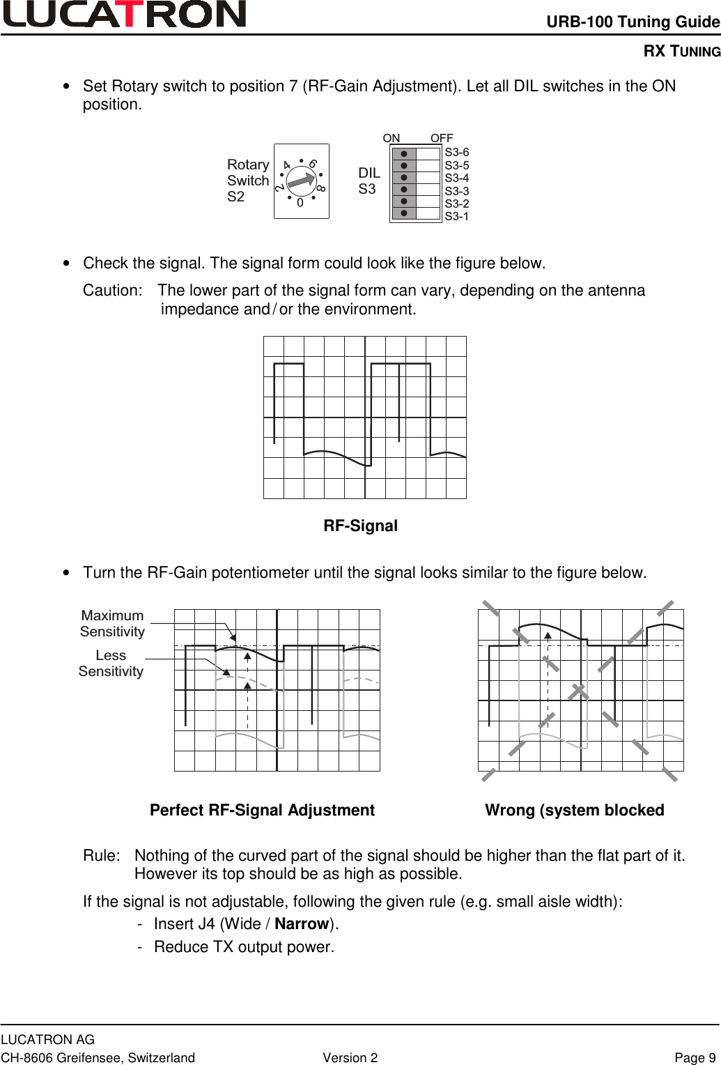
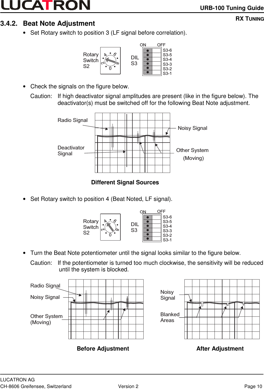
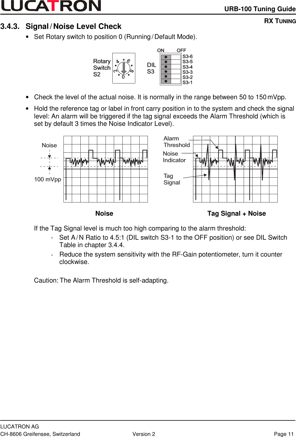
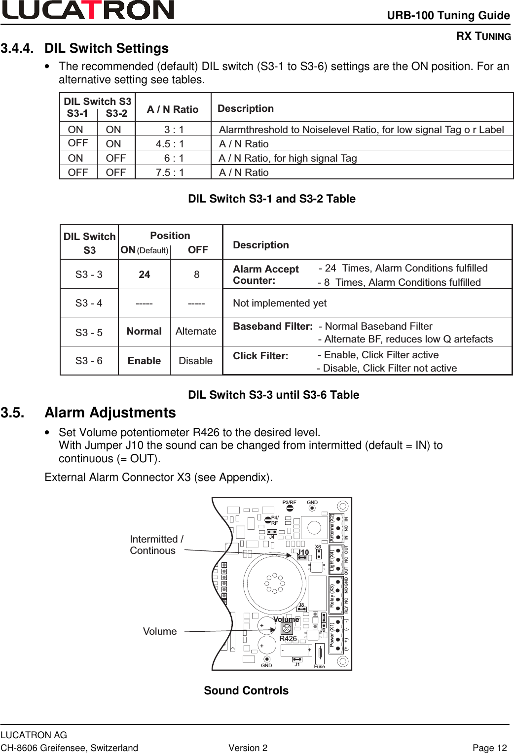
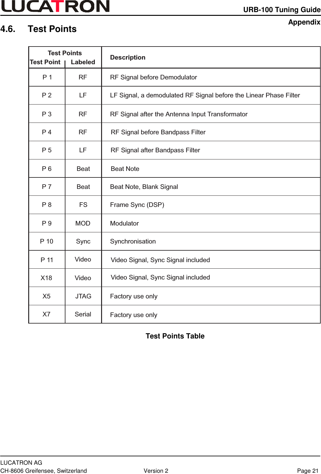
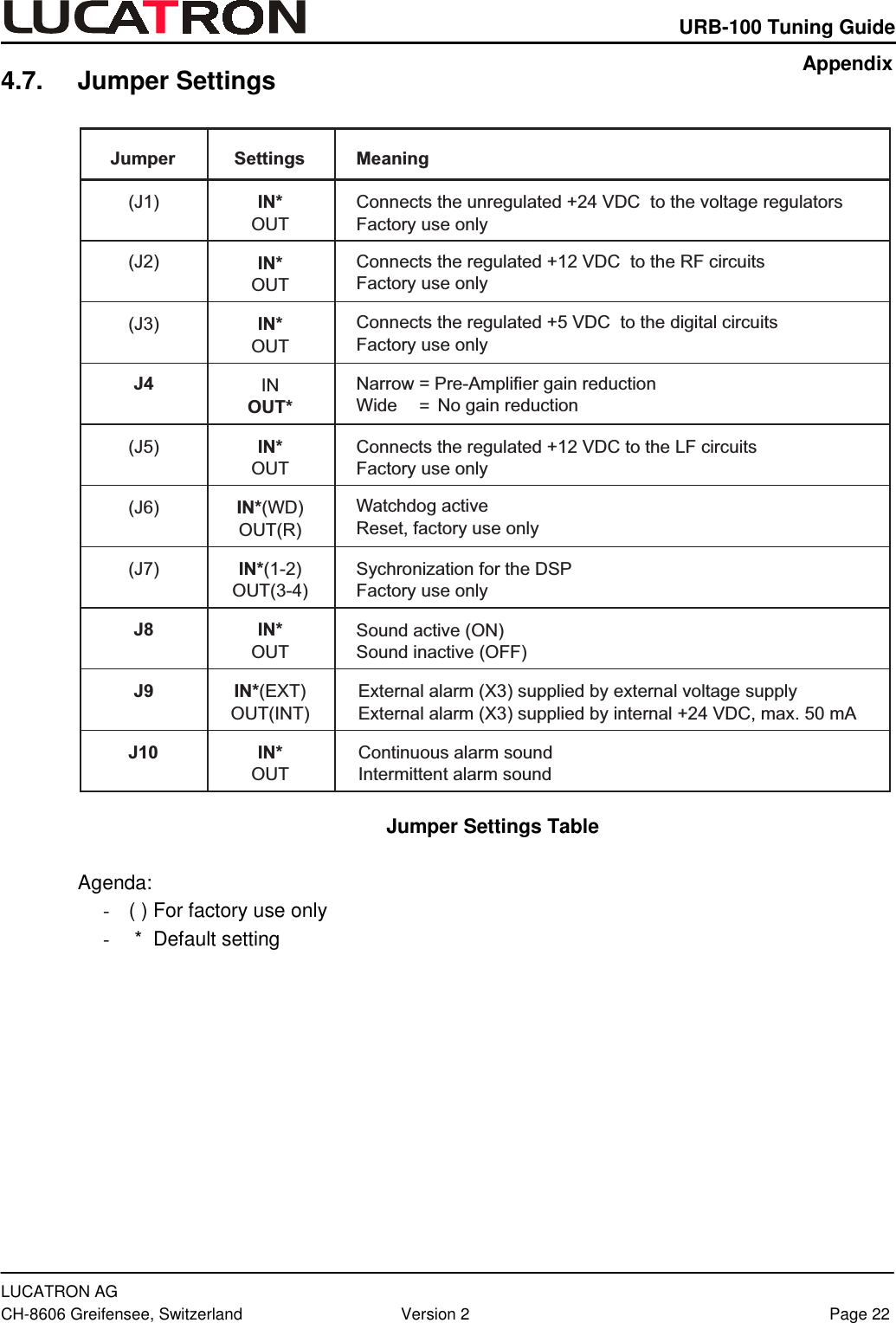
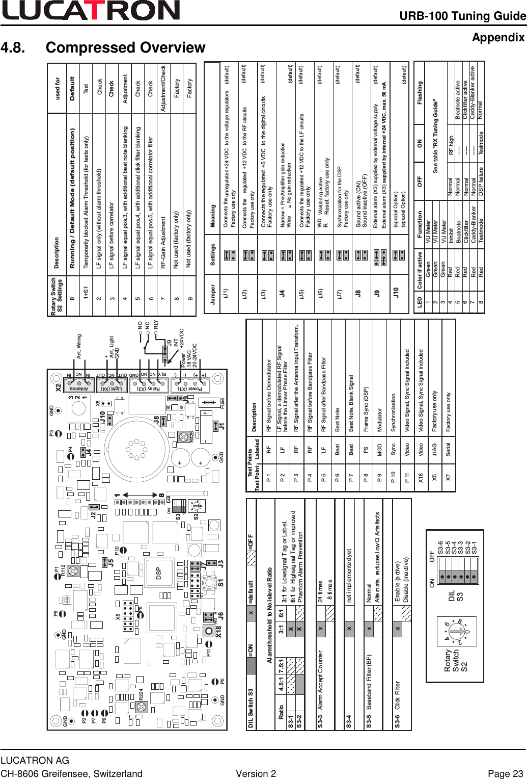
SenTech EAS AQUILA User Manual Basic Description Receiver Electronics
SenTech EAS Corporation Basic Description Receiver Electronics
UserManual.wiki
>
SenTech EAS
>
AQUILA User Manual
>
receiver manual
Contents
1.
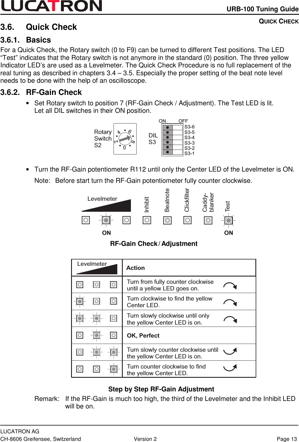
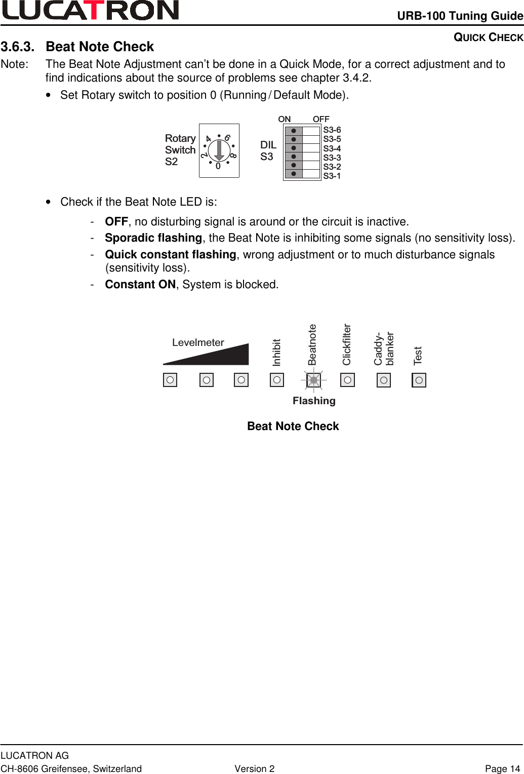
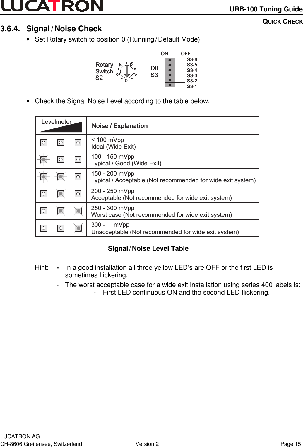
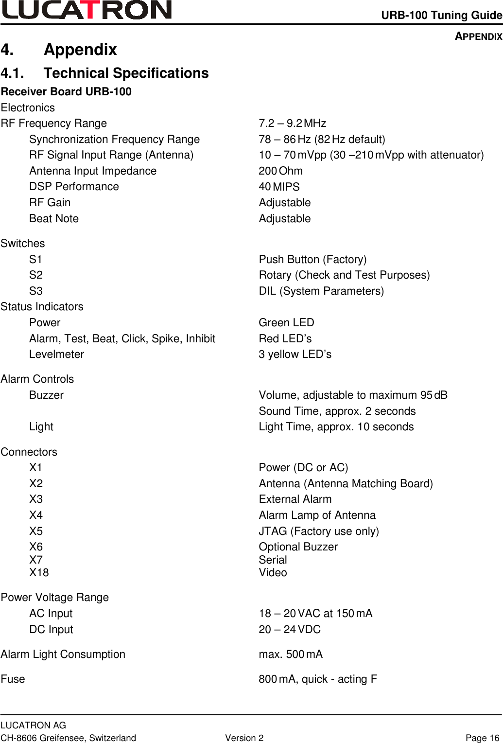
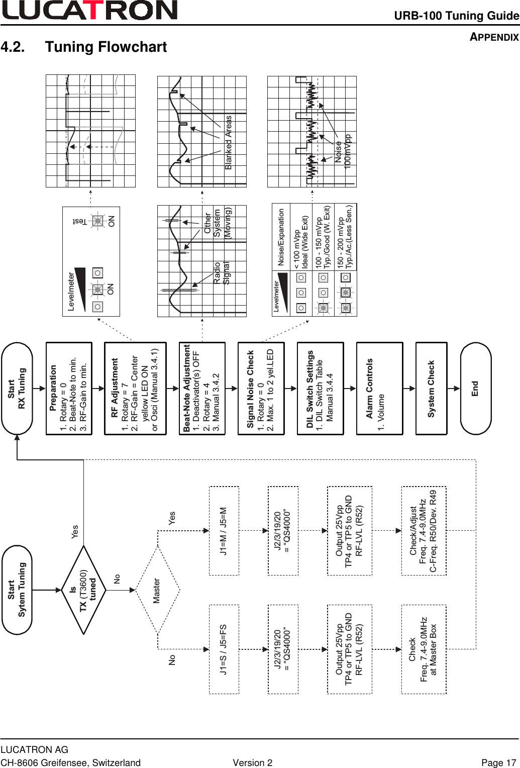
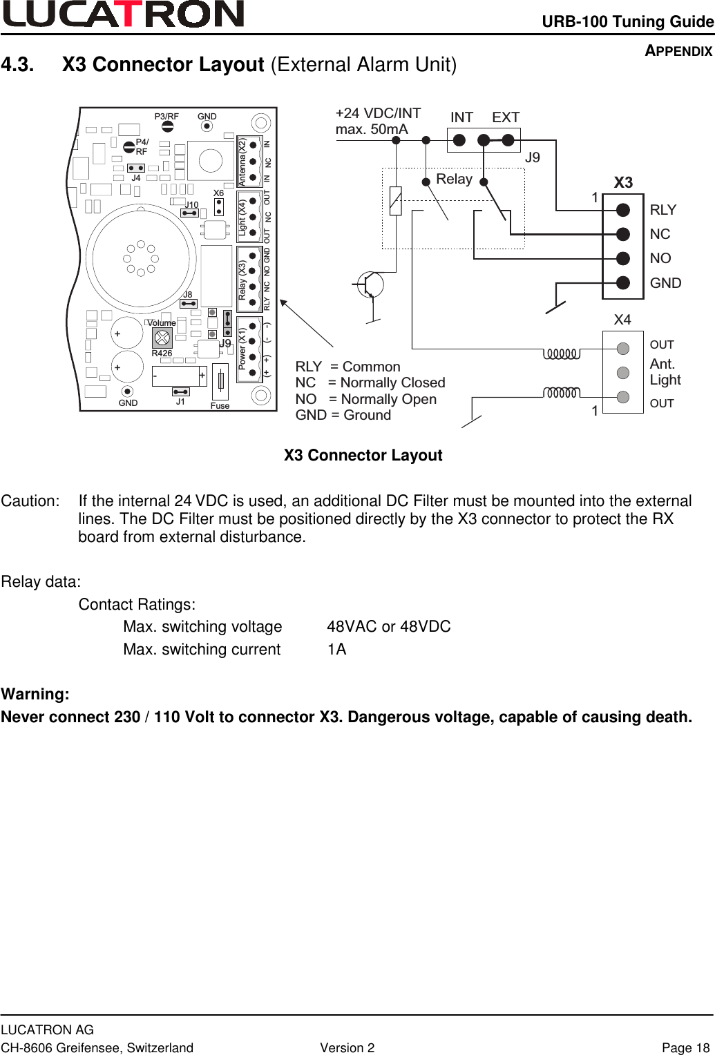
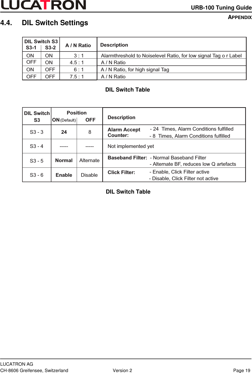
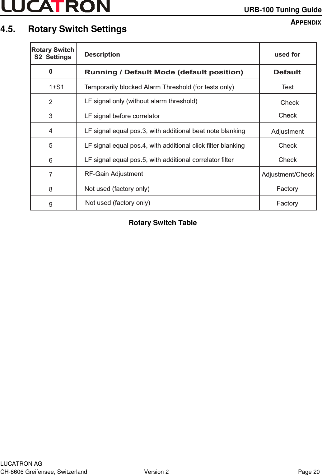
receiver manual
2.
transmitter manual
receiver manual
Navigation menu
Upload a User Manual
Namespaces
Wiki Guide
HTML
PDF
Info
Views
User Manual
Discussion / Help
Navigation