Sercomm RV180W Wireless-N Multifunction VPN Firewall User Manual rv180w admin
Sercomm Corporation Wireless-N Multifunction VPN Firewall rv180w admin
UserManual.wiki
>
Sercomm
>
RV180W User Manual
>
User Manual
Contents
1.
User Manual
2.
User Manual - Statements
User Manual
Navigation menu
Upload a User Manual
Namespaces
Wiki Guide
HTML
PDF
Info
Views
User Manual
Discussion / Help
Navigation


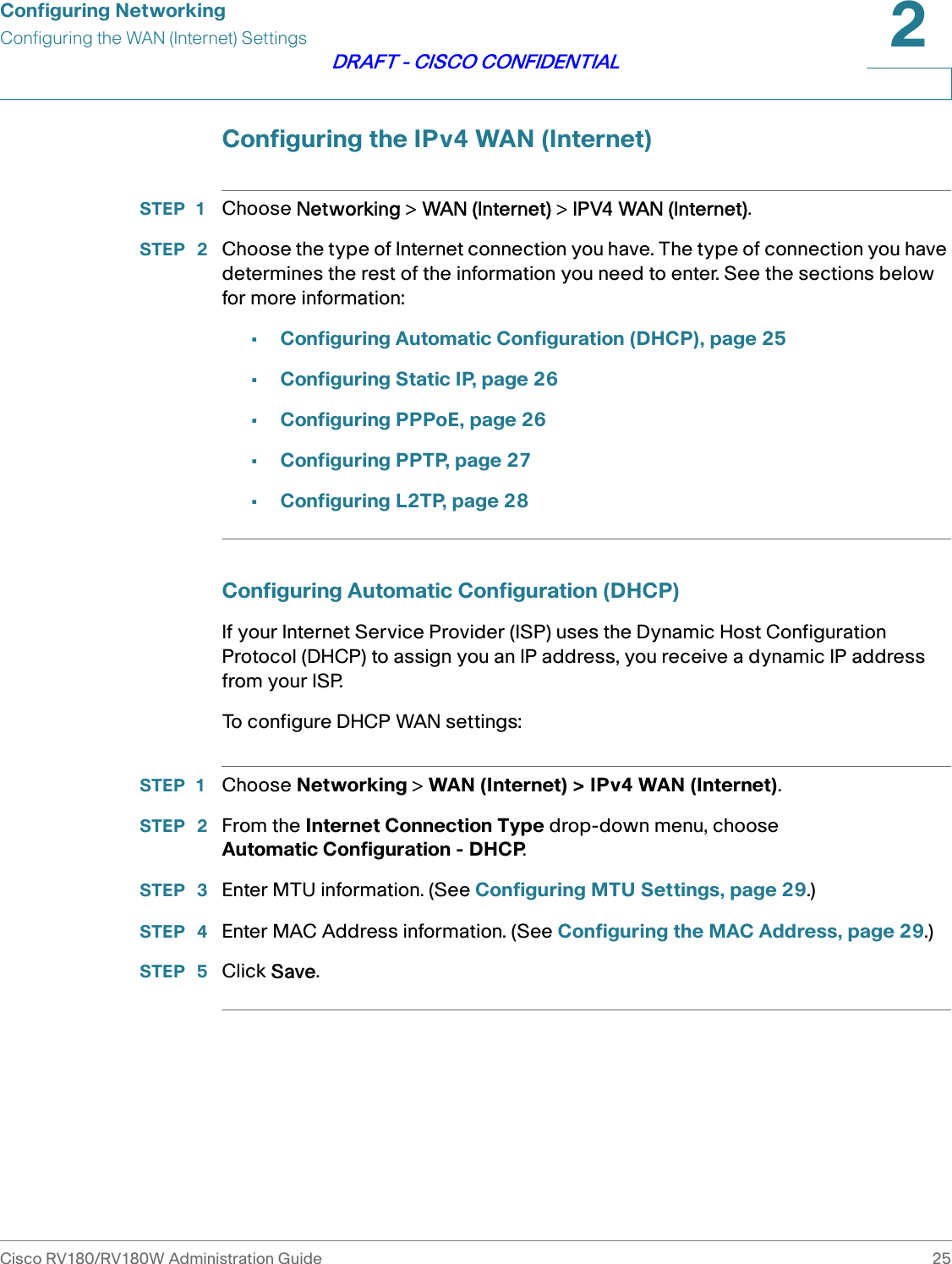
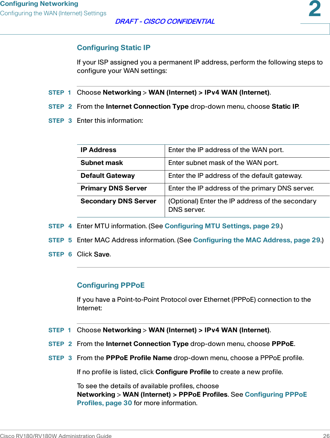
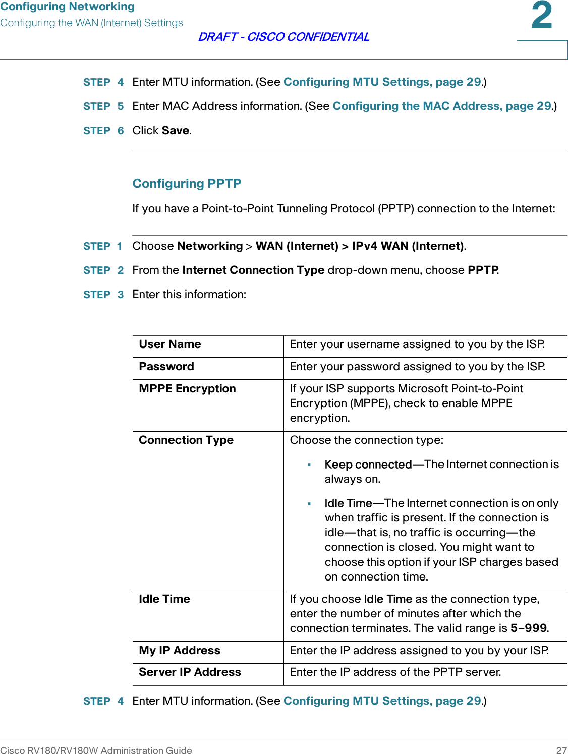
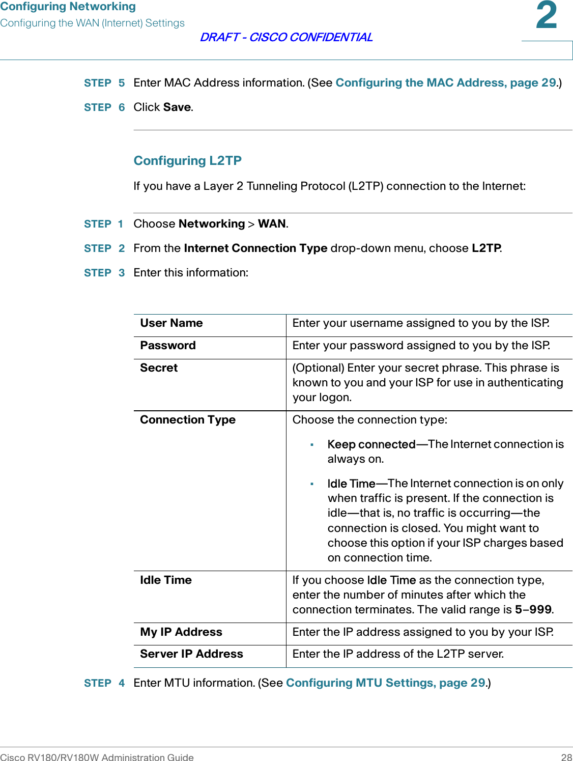
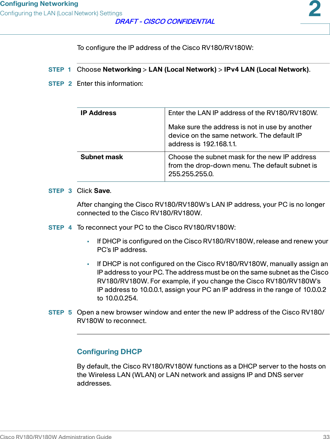
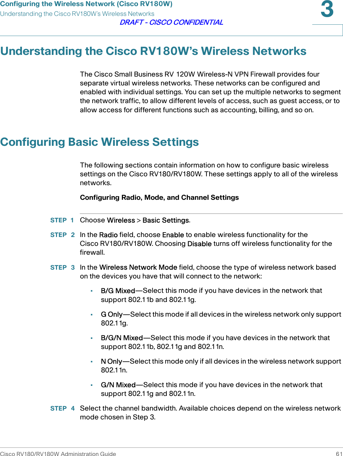
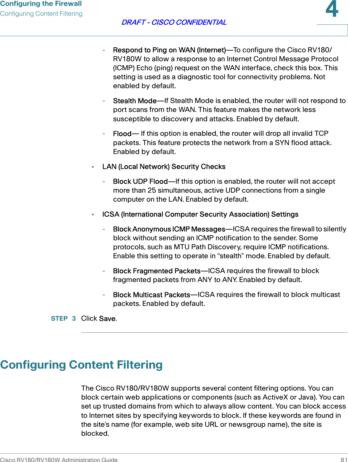
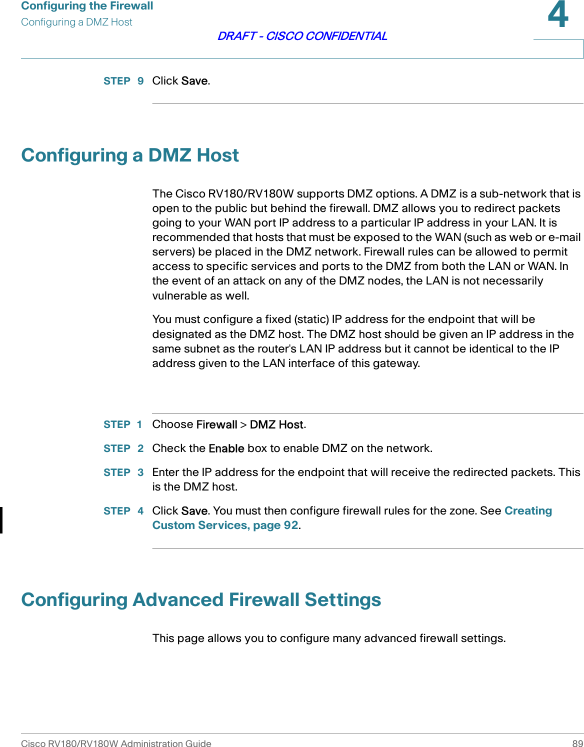
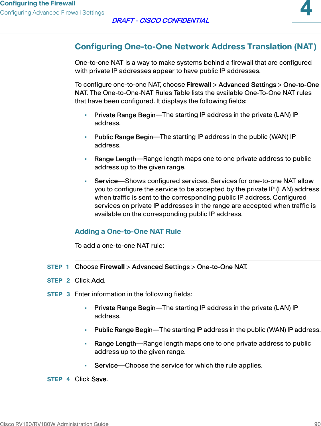
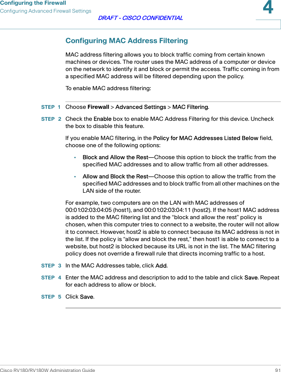
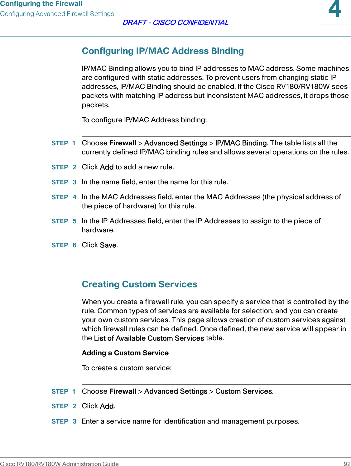
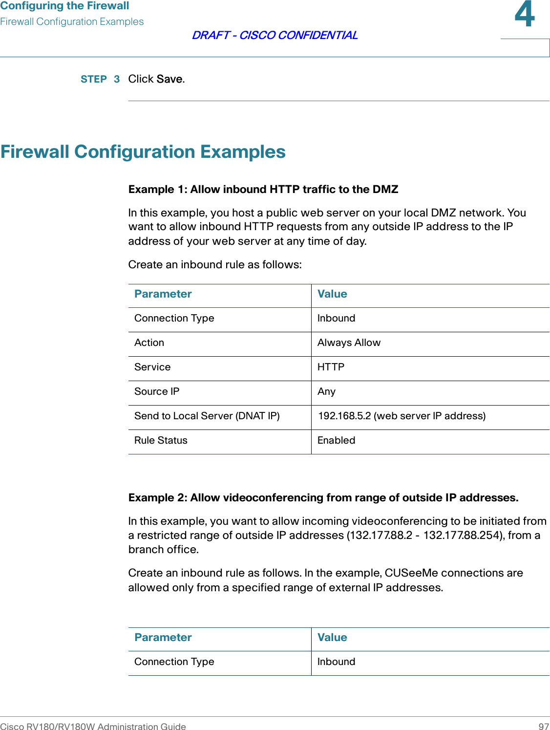
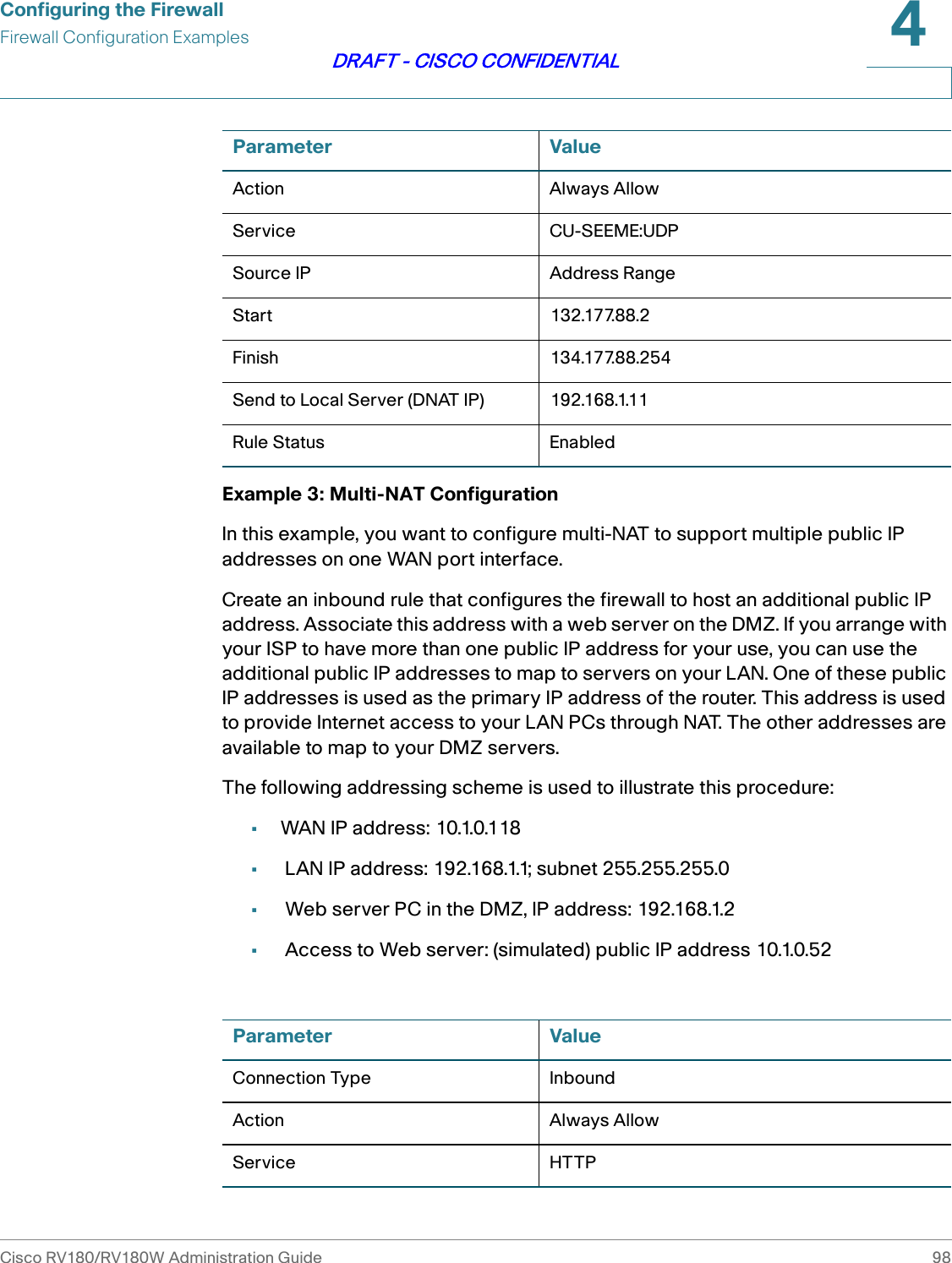
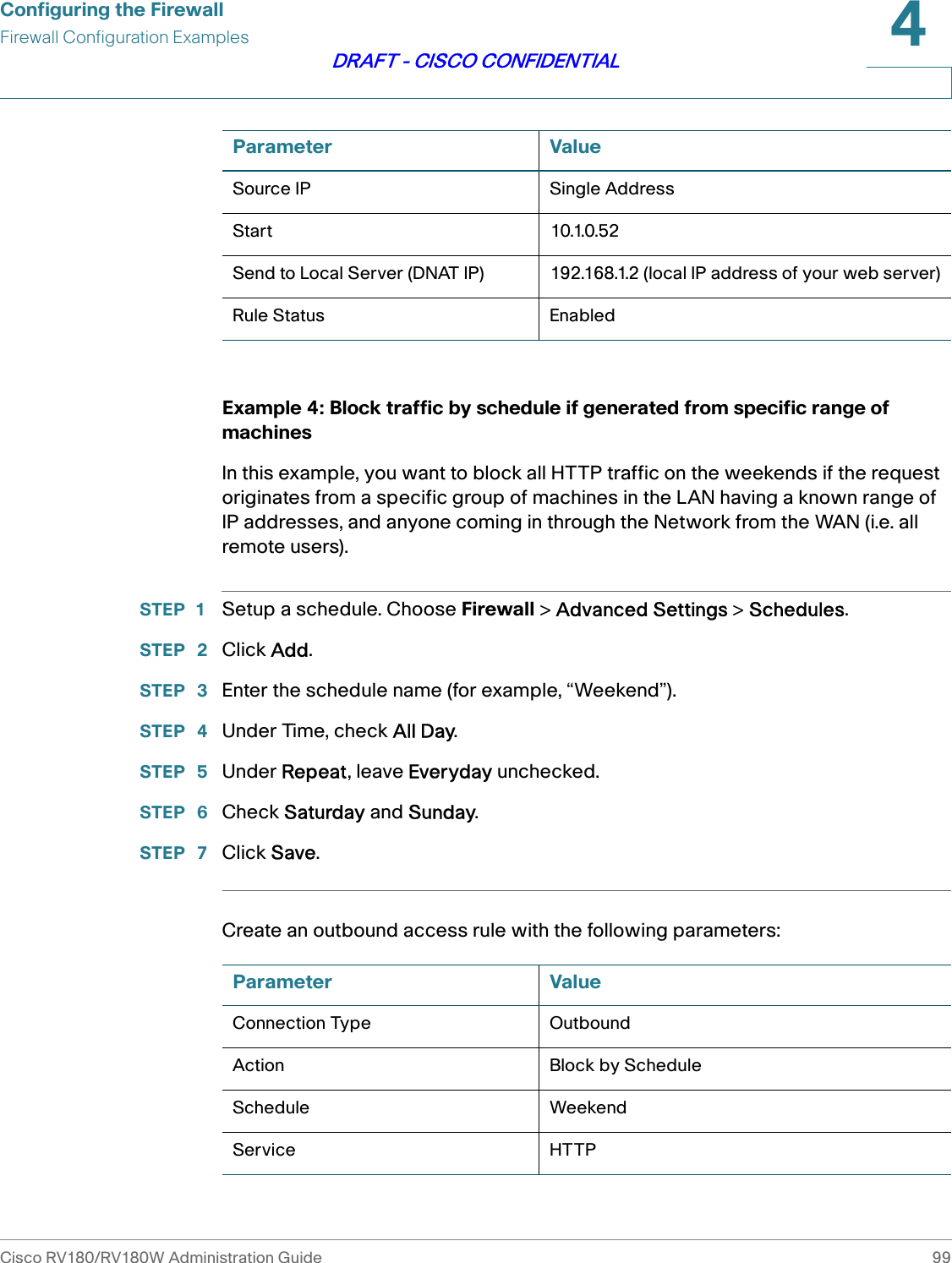
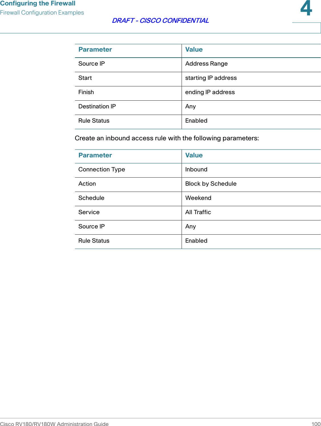
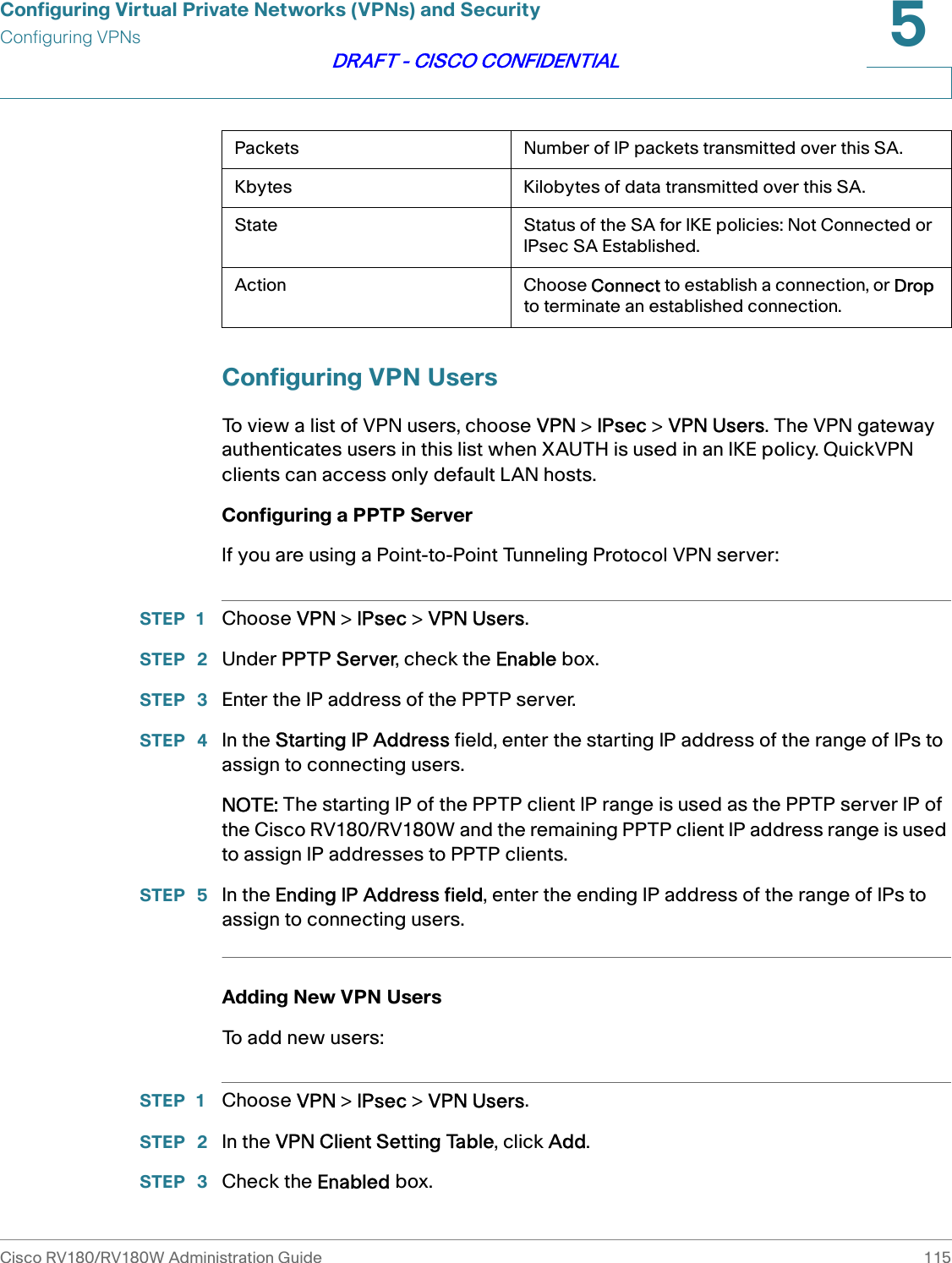
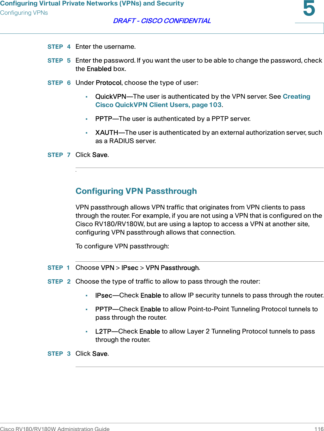
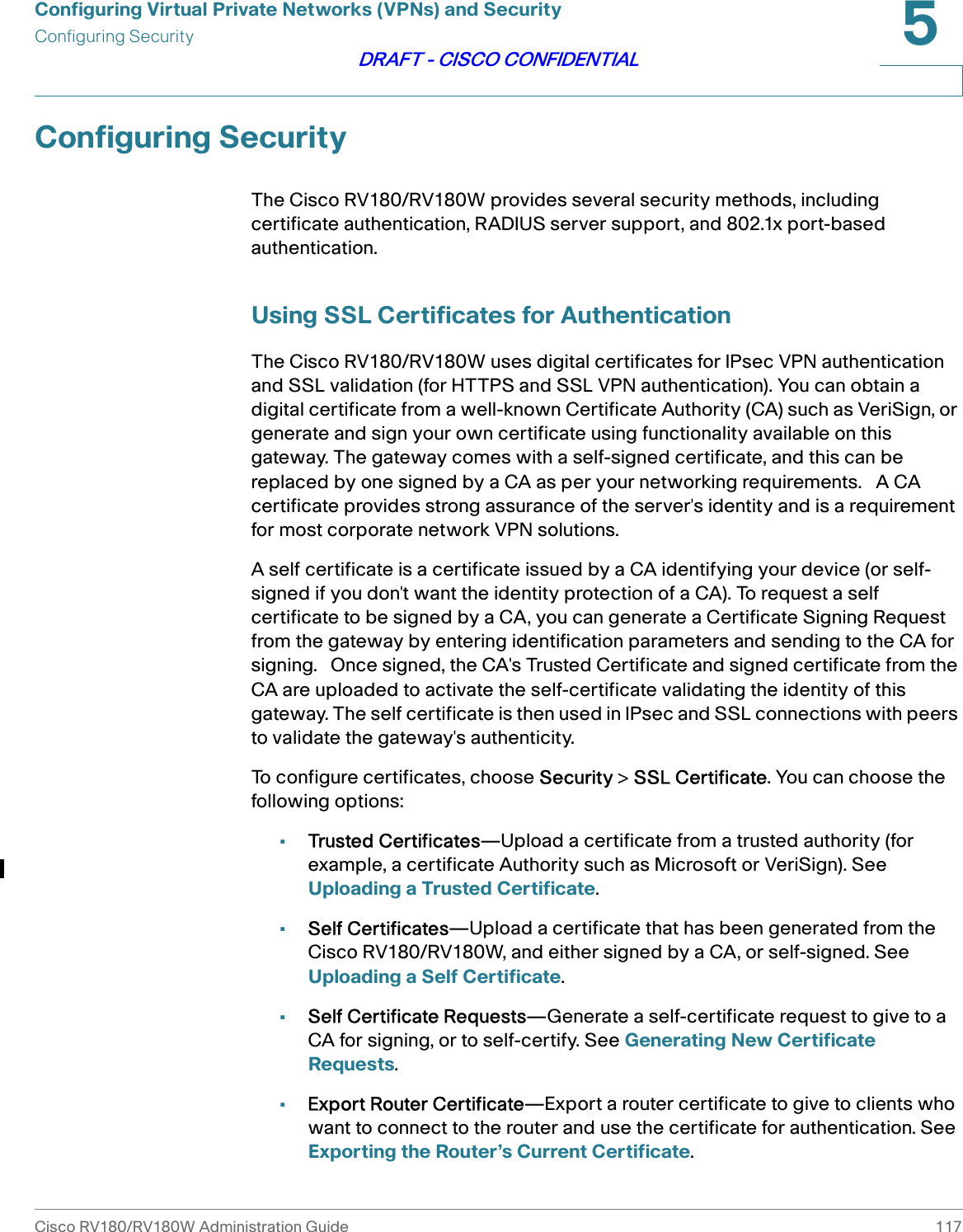
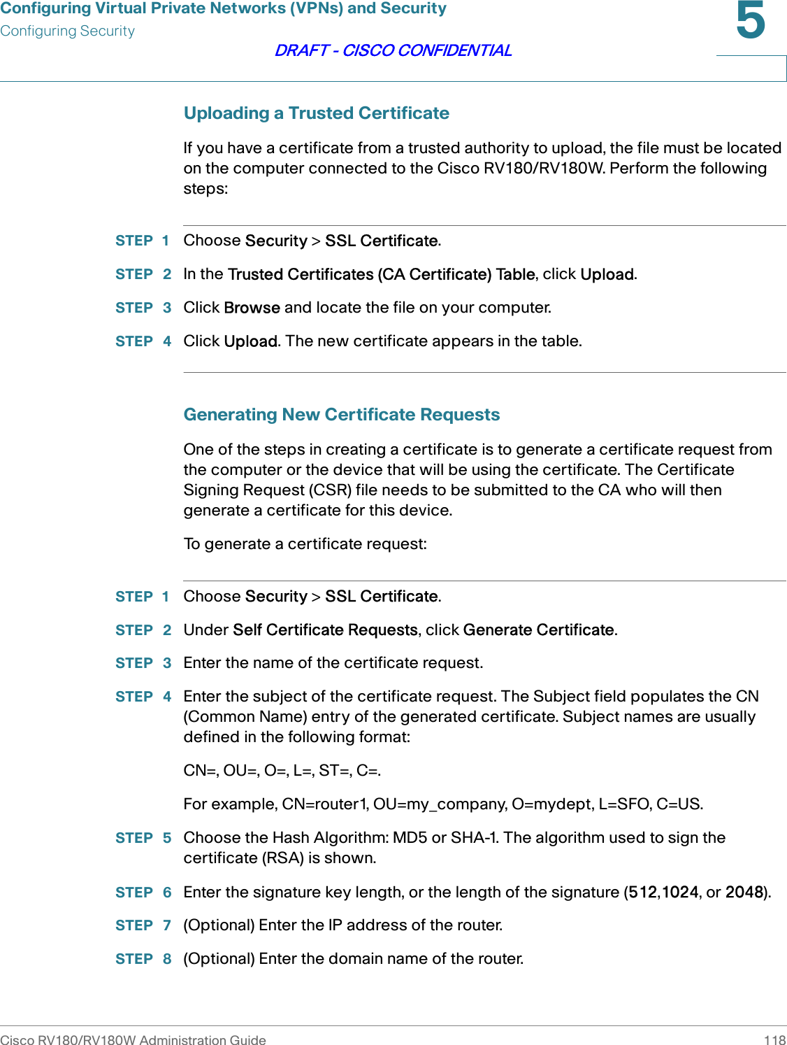
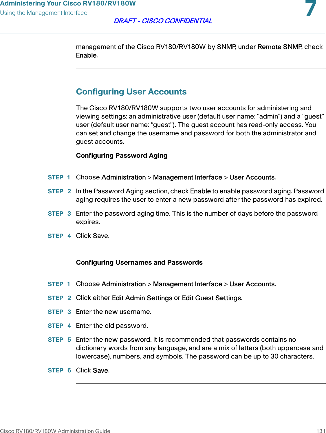
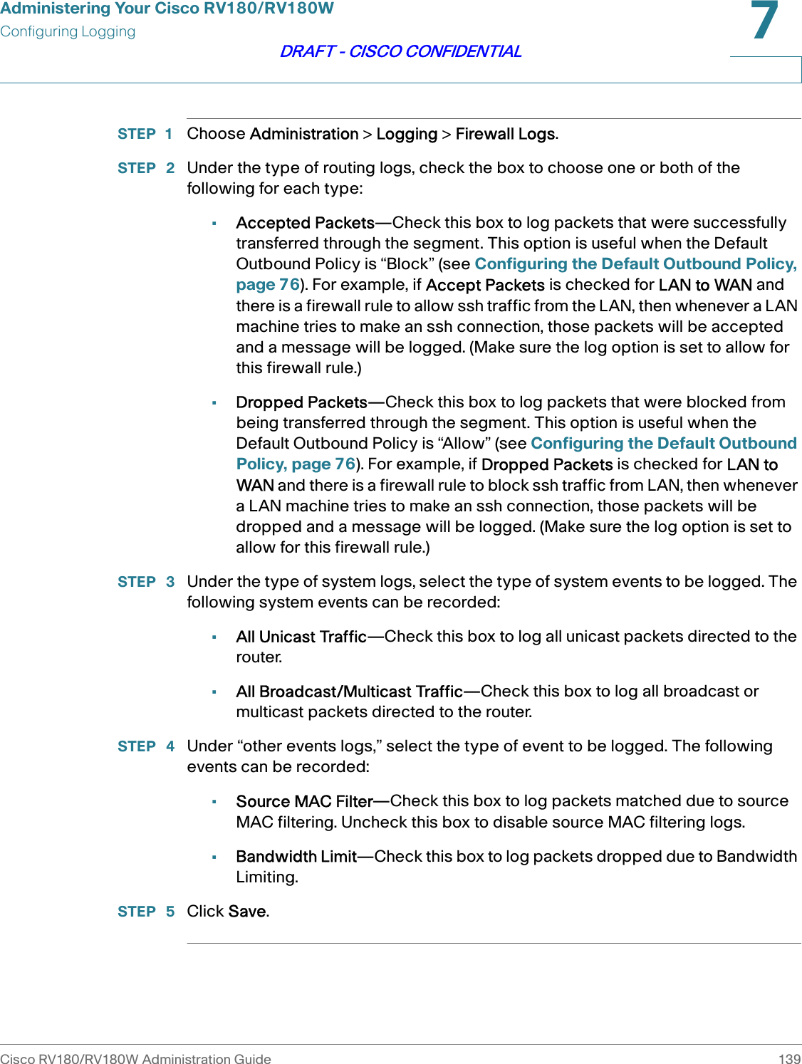
![Configuring NetworkingConfiguring IPv6Cisco RV180/RV180W Administration Guide 552DRAFT - CISCO CONFIDENTIALTo configure the RADVD:STEP 1 Choose Networking > IPv6 > Router Advertisement.STEP 2 Under Router Advertisement Status, choose Enable.STEP 3 Under Advertise Mode, choose one of the following:•Unsolicited Multicast—Select this option to send router advertisements (RAs) to all interfaces belonging to the multicast group.•Unicast only—Select this option to restrict advertisements to well-known IPv6 addresses only (router advertisements [RAs] are sent to the interface belonging to the known address only).STEP 4 If you chose Unsolicited Multicast in Step 3, enter the advertise interval. The advertise interval is a random value between the Minimum Router Advertisement Interval and Maximum Router Advertisement Interval. (MinRtrAdvInterval = 0.33 * MaxRtrAdvInterval.) The default is 30 seconds.STEP 5 Under RA Flags, check Managed to use the administered/stateful protocol for address auto configuration. Check Other to use the administered/stateful protocol of other, non-address information auto configuration.STEP 6 Under router preference, choose Low, Medium, or High. The router preference provides a preference metric for default routers. The low, medium and high values are signaled in unused bits in Router Advertisement messages. This extension is backward compatible, both for routers (setting the router preference value) and hosts (interpreting the router preference value). These values are ignored by hosts that do not implement router preference. This feature is useful if there are other RADVD-enabled devices on the LAN. The default is high. STEP 7 Enter the MTU size. The MTU is the size of the largest packet that can be sent over the network. The MTU is used in RAs to ensure all nodes on the network use the same MTU value when the LAN MTU is not well-known. The default is 1500 bytes.STEP 8 Enter the router lifetime value, or the time in seconds that the advertisement messages will exist on the route. The default is 3600 seconds.STEP 9 Click Save.Configuring Router Advertisement PrefixesTo configure the RADVD available prefixes:](https://usermanual.wiki/Sercomm/RV180W.User-Manual/User-Guide-1611583-Page-64.png)