Topcon America 090521 GNSS Receiver User Manual Introduction
Topcon America Corporation GNSS Receiver Introduction
UserManual.wiki
>
Topcon America
>
090521 User Manual
>
GRX1 Operation Manual 1
Contents
1.
GRX1 Operation Manual 1
2.
GRX1 Operation Manual 2
3.
GRX1 Operation Manual 3
4.
HiPerII Operation Manual 1
5.
HiPerII Operation Manual 2
6.
HiPerII Operation Manual 3
GRX1 Operation Manual 1
Navigation menu
Upload a User Manual
Namespaces
Wiki Guide
HTML
PDF
Info
Views
User Manual
Discussion / Help
Navigation
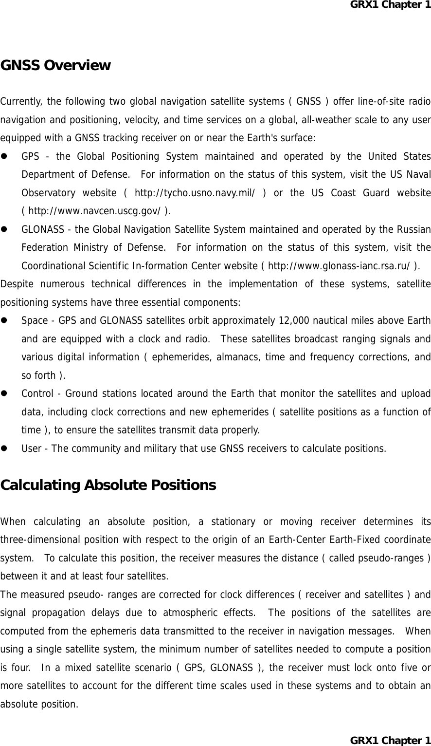
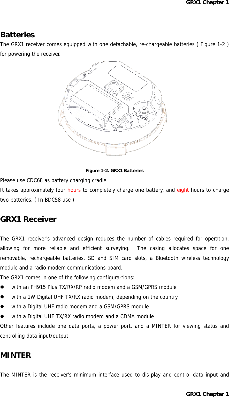
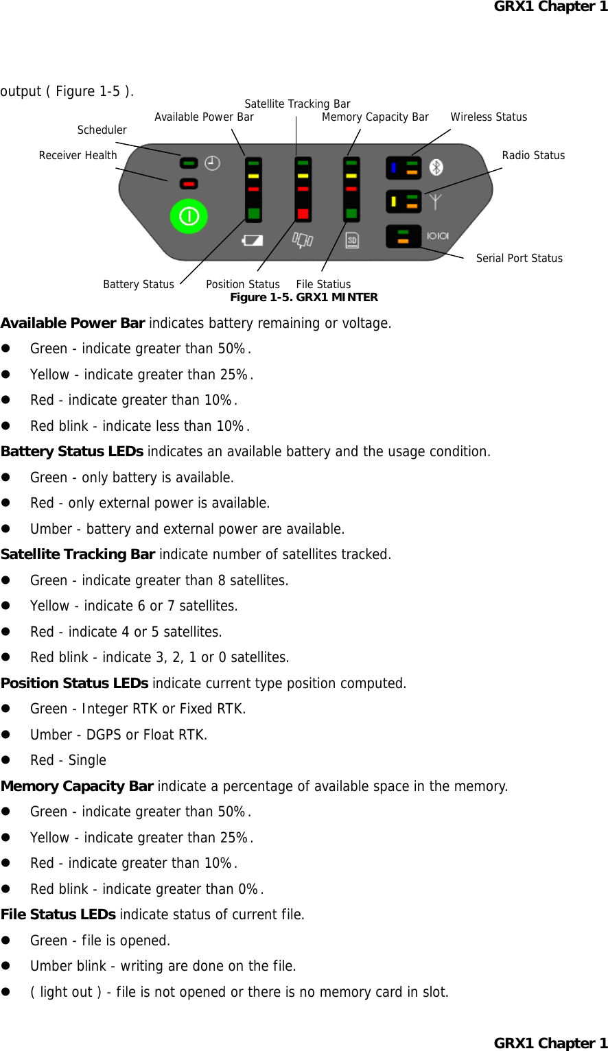
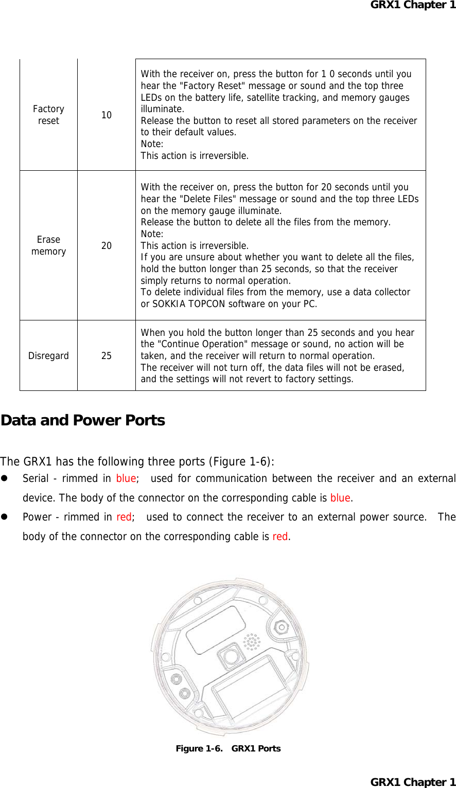
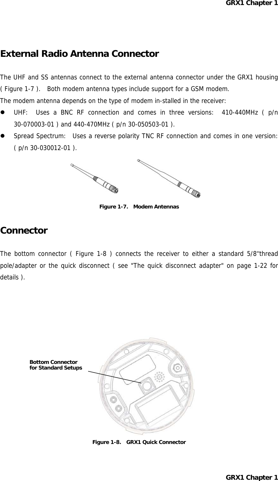
![GRX1 Chapter 1 Cables The GRX1 package includes standard communication cables for configuring the receiver. Table 1-3 lists the cables included in the GRX1 package. Table 1 -3. GRX1 Package Cables Cable Description Cable Illustration Serial Cable Connects the receiver to an external device ( controller or computer data transfer and receiver configuration. Body of connector back. p/n xx-xxxxxx-xx Other Accessories Battery ( BDC58 ) Li-ion Battery [ 4300mAh,7.2V DC ]. Power system - without Power Cable ( CDC68 ) Battery BDC58 [ about 150min ] × 2、AC100V [ without AC power cable、CDC68-11 include ] Power Cable ( EDC113/A/B/C/D/E ) CDC68 to AC consent. It is chosen by every country. Quick release ( 086-0-0001 ) Measuring Tape ( 405-0-0013 ) 3.7m HI ( Calibrated ) SD Card FAT16、2GB industrial CD-ROM include Manual PDF and Config Tool Carrying Case For more details on the accessories and package options available for the GRX1, contact the local Sokkia Topcon dealer. GRX1 Chapter 1](https://usermanual.wiki/Topcon-America/090521.GRX1-Operation-Manual-1/User-Guide-1163497-Page-12.png)