Trio Datacom QB450QP450 UHF Base Station (Data) User Manual
Trio Datacom Pty Ltd (a wholly owned company of Schneider Electric) UHF Base Station (Data)
UserManual.wiki
>
Trio Datacom
>
QB450QP450 User Manual
>
User Manual
Contents
1.
User Manual
2.
Users Manual
User Manual
Navigation menu
Upload a User Manual
Namespaces
Wiki Guide
HTML
PDF
Info
Views
User Manual
Discussion / Help
Navigation
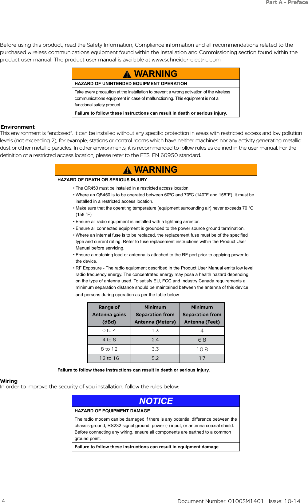
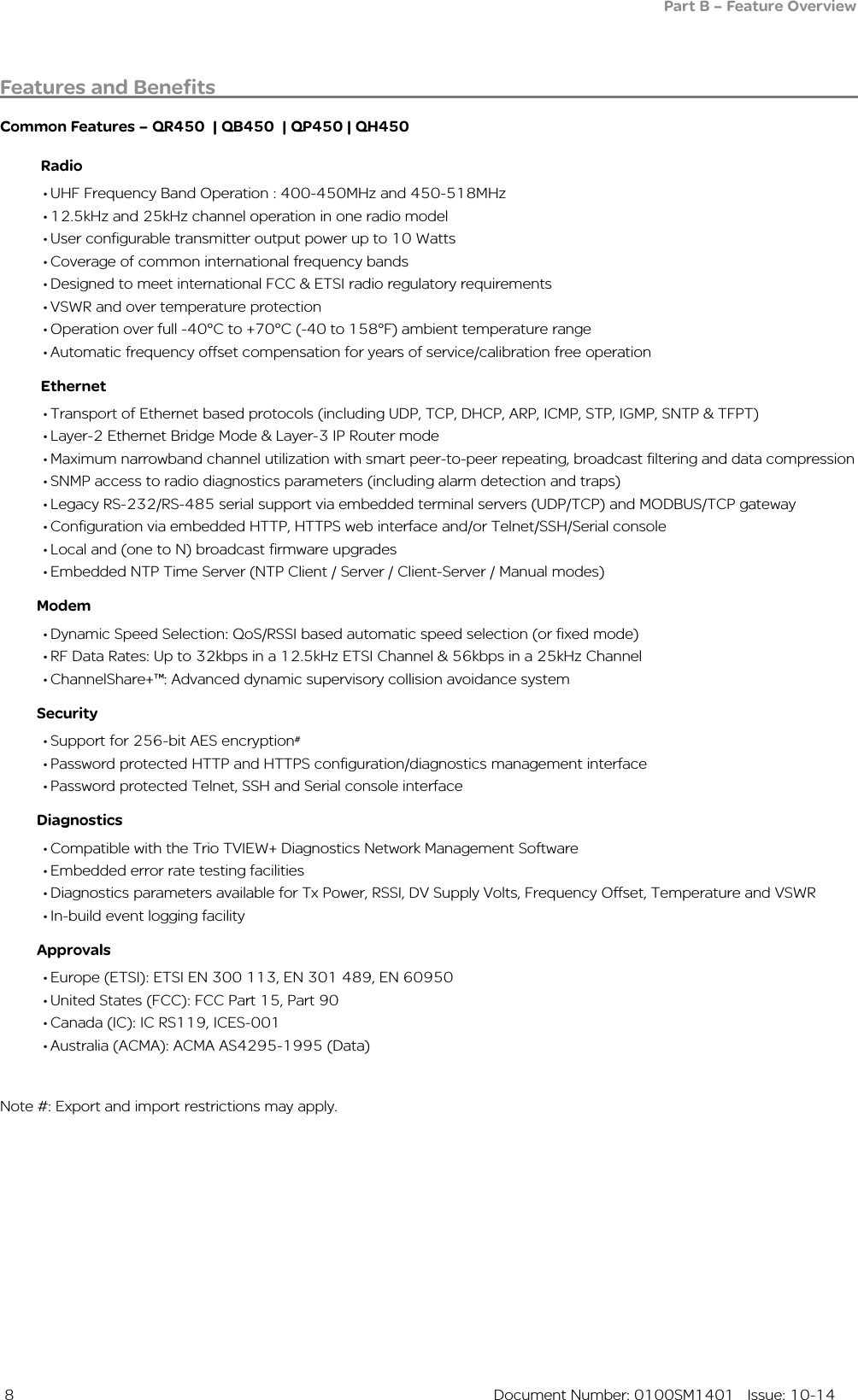
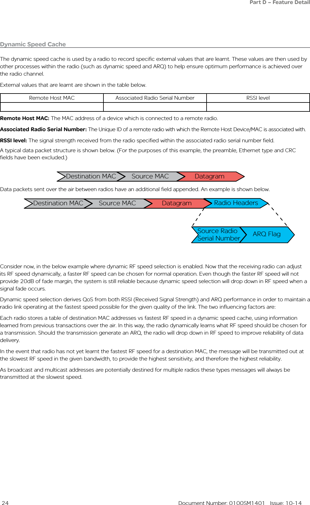
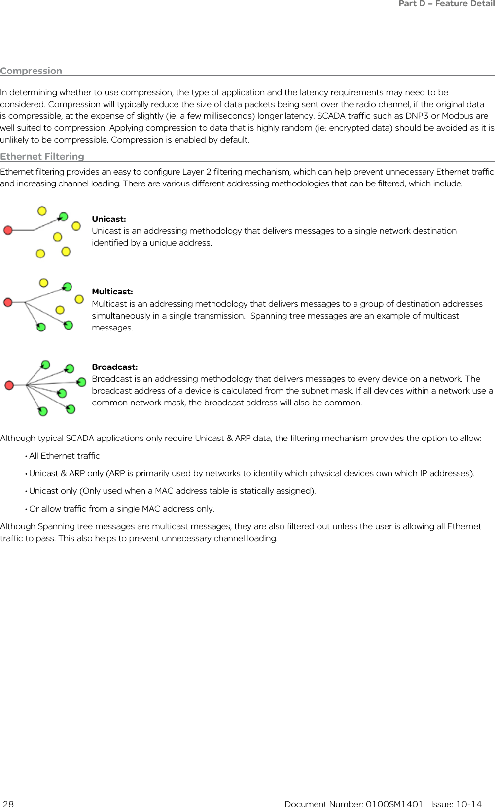
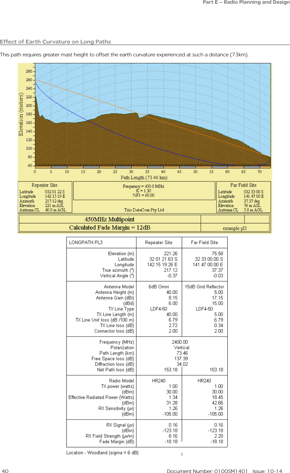
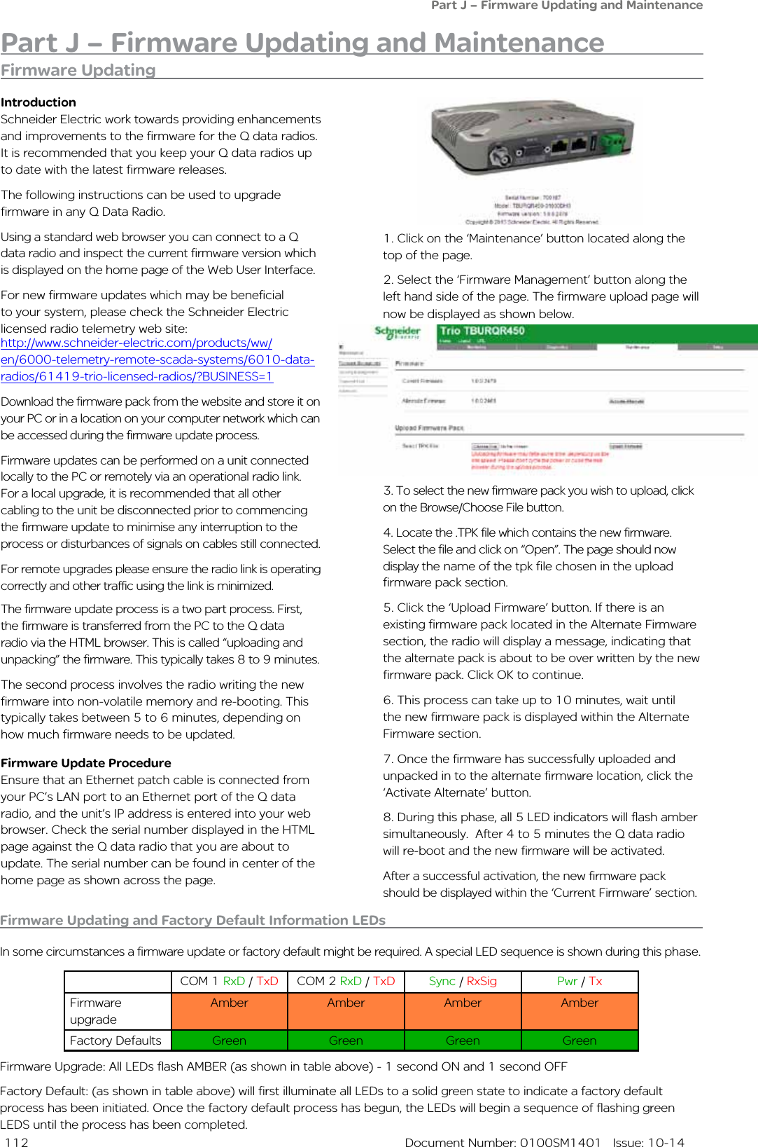
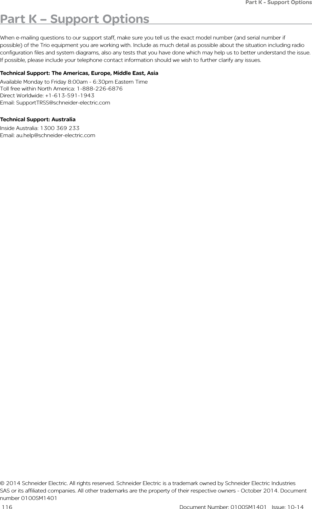
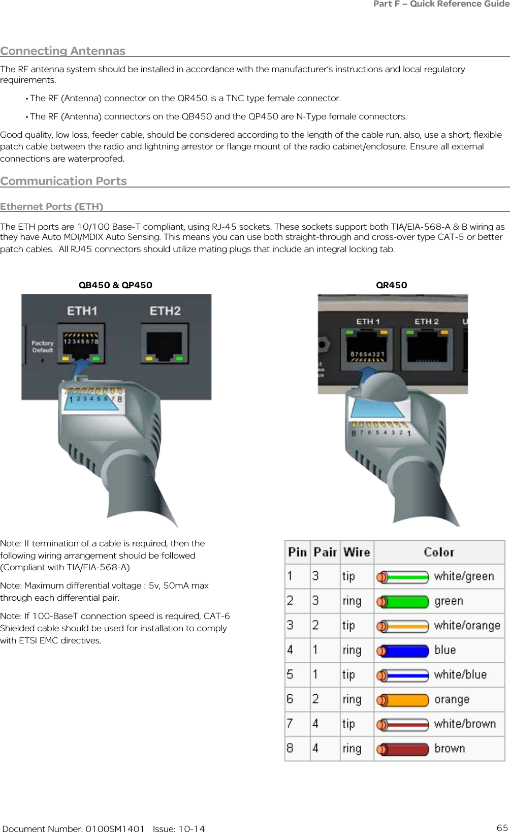
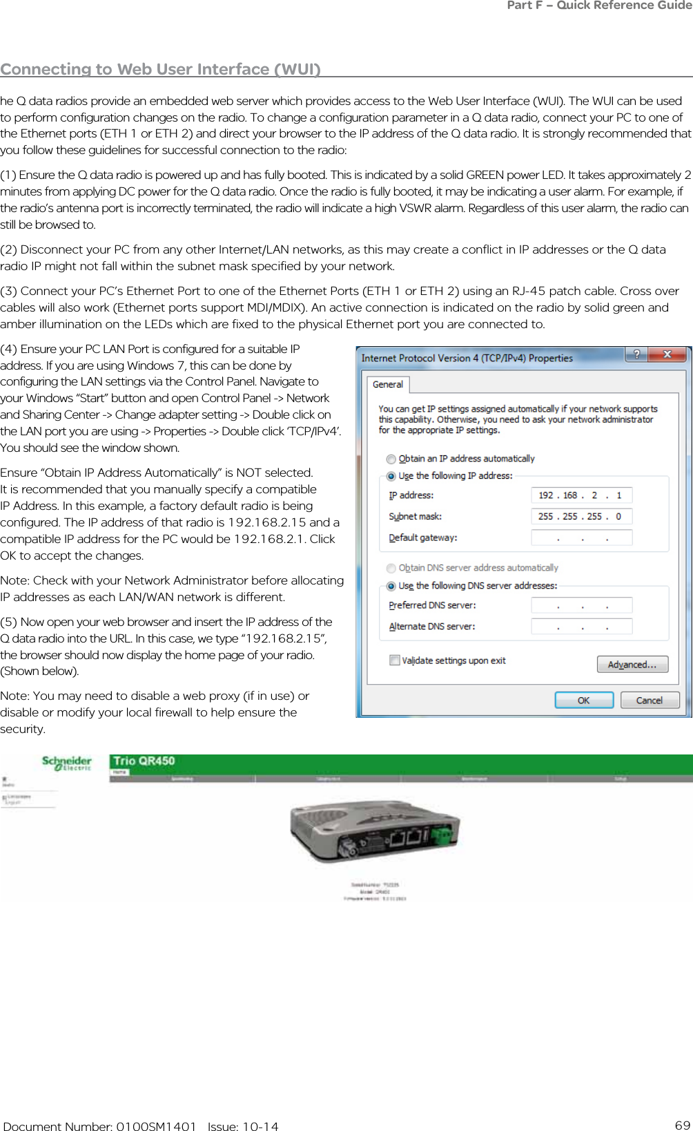
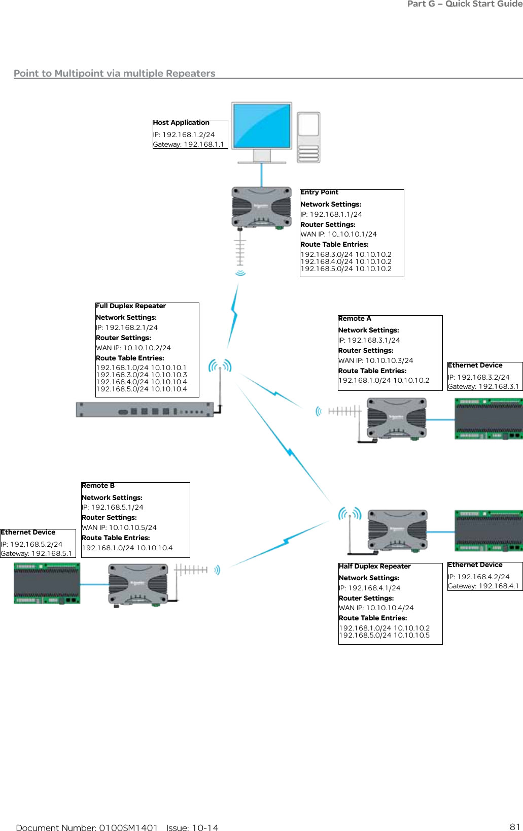
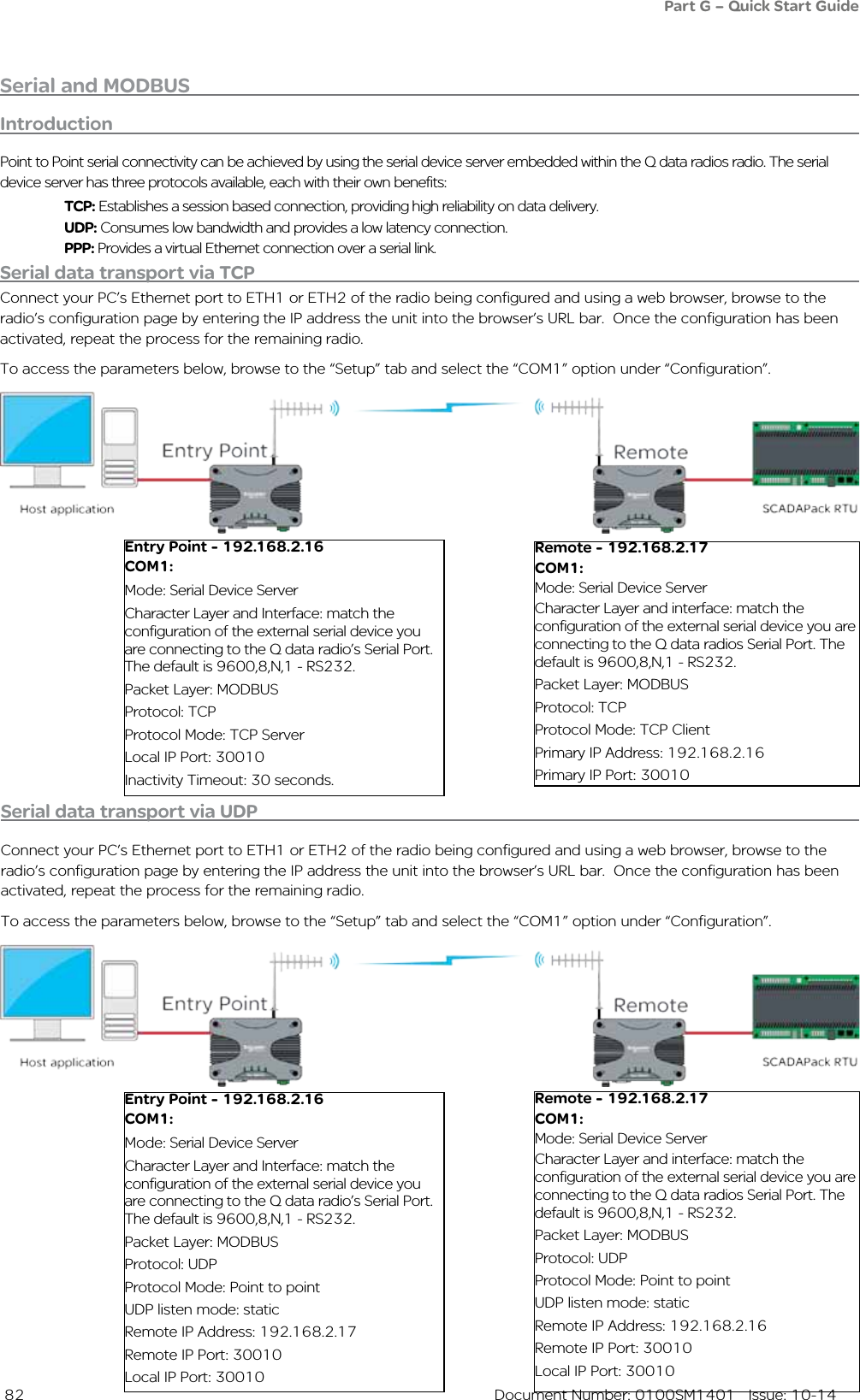
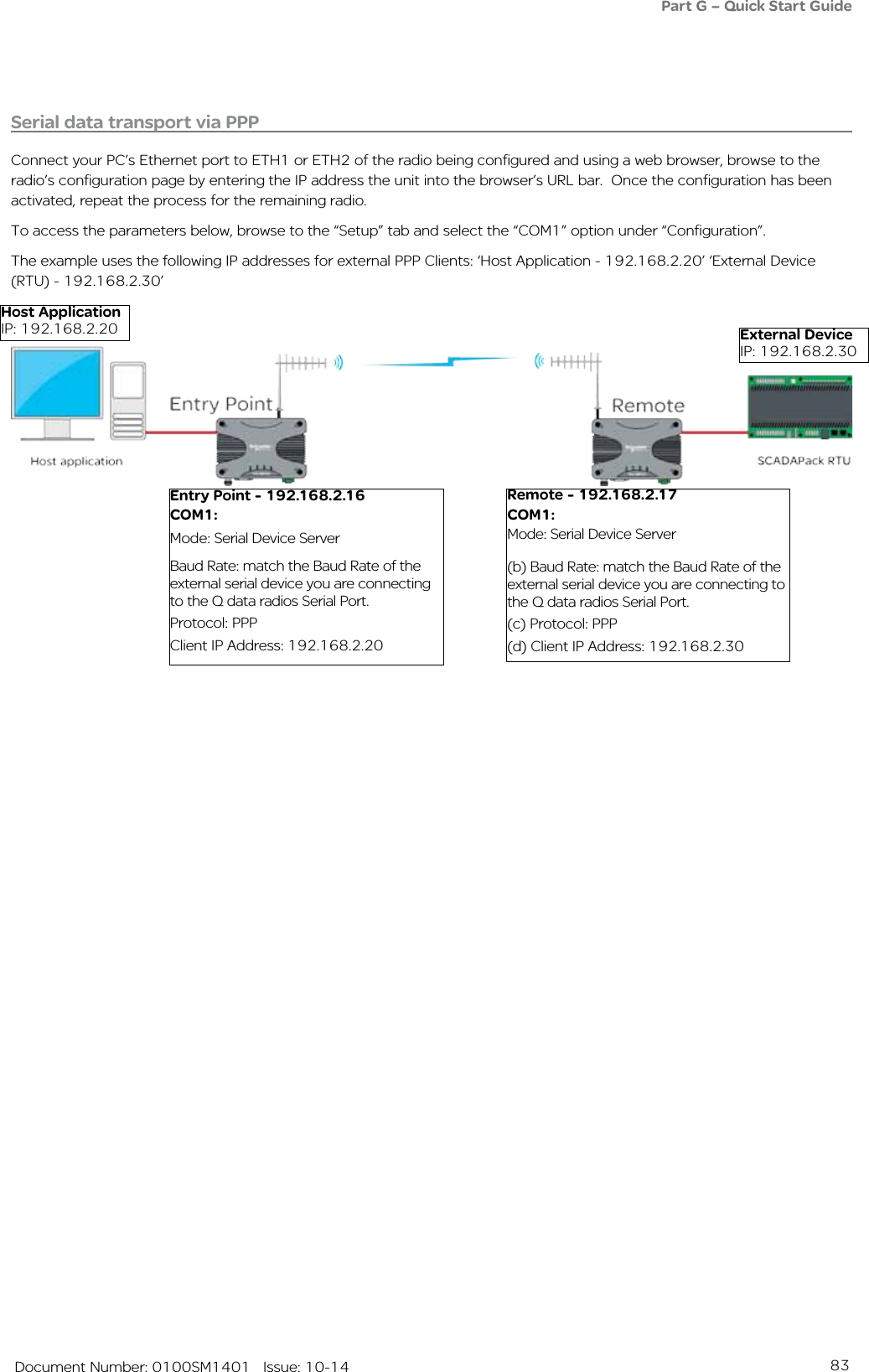
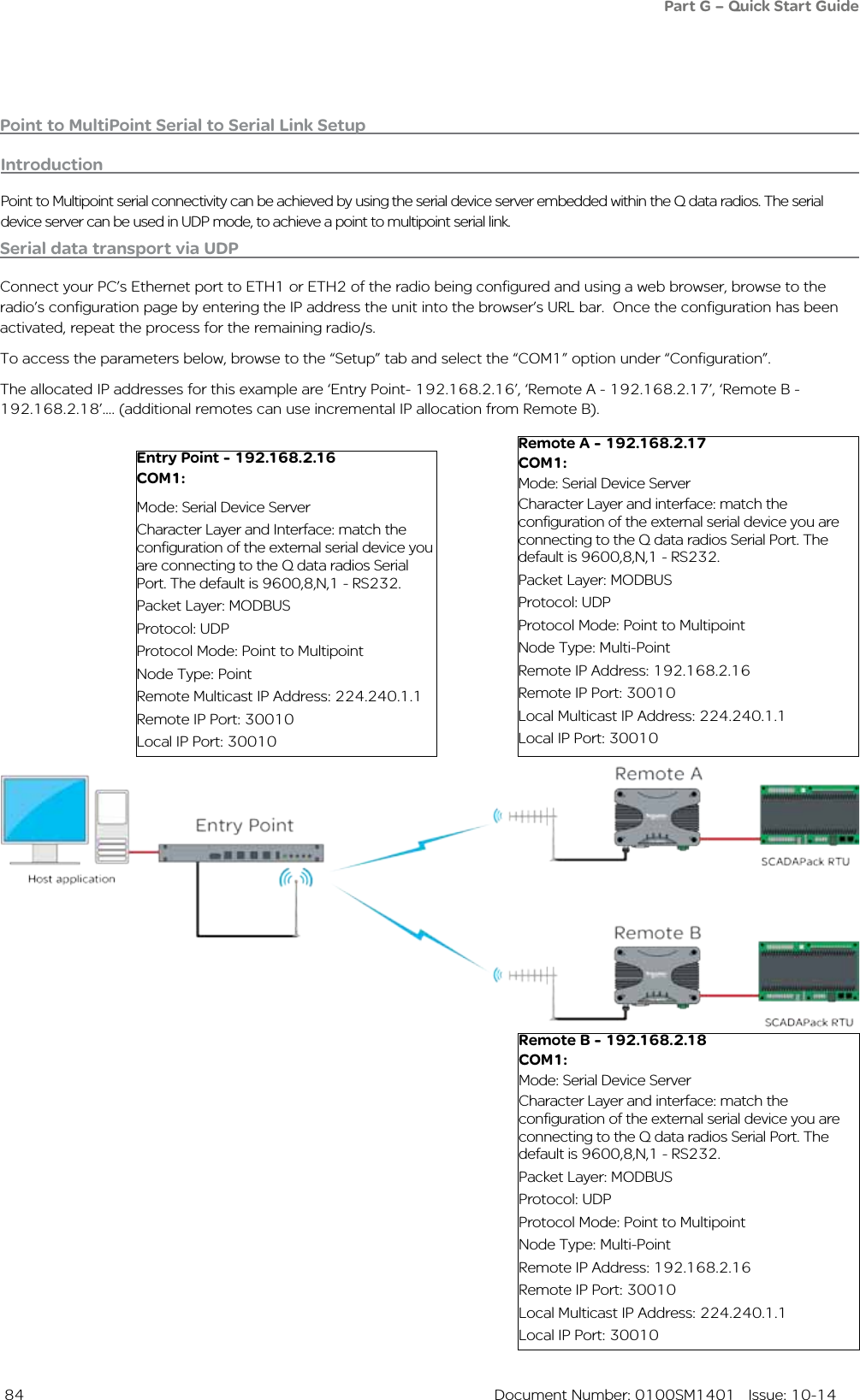
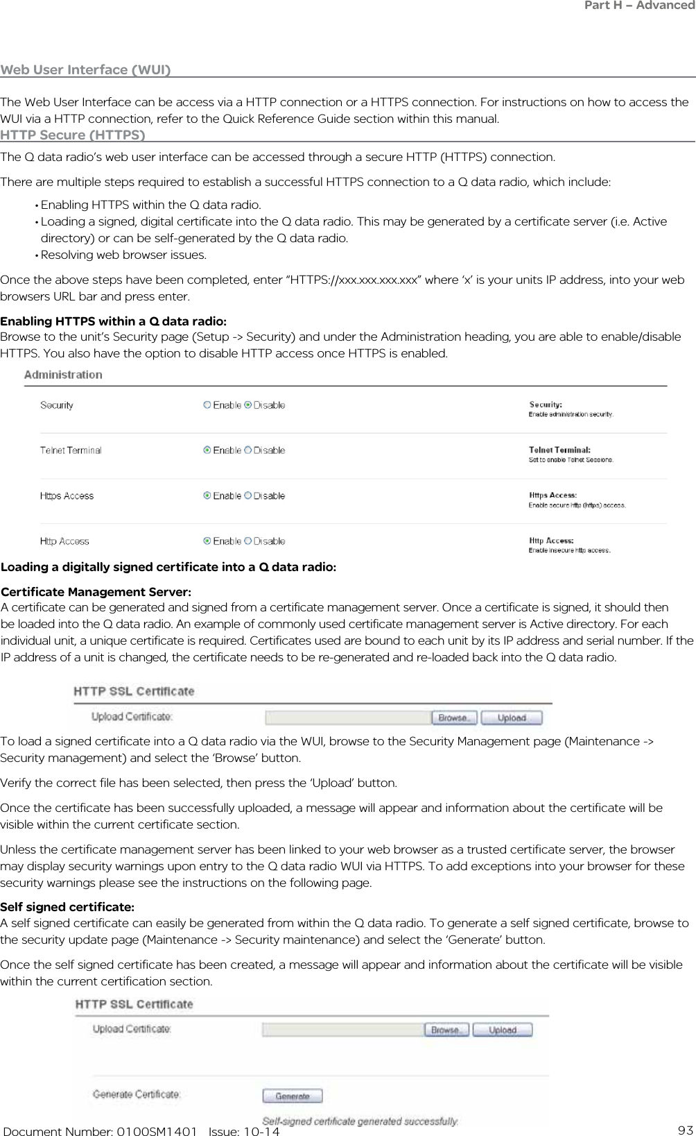
![46 Document Number: 0100SM1401 Issue: 10-14DIN rail mounting kitAn optional DIN rail mounting kit is available for the QR450. The Mount is screwed onto the bottom of the QR450 giving the unit the ability to be simply ‘clipped’ and Locked onto 7.5 mm by 35 mm (0.3 in. x 1.4 in.) DIN rail.Each DIN rail kit supplies:• A DIN rail mounting bracket• A Phoenix DIN rail clip• x4 Countersunk M4X8 screws (to mount DIN rail clip to bracket)• x4 M4 nuts (to mount DIN rail clip to bracket)• x4 Pan head M3X6 screws (to mount Spread spectrum radio to bracket)• x4 Pan head M4X2.5 screws (to mount M-Series to bracket)• x4 Pan head M4X8 screws (to mount QR450 to bracket)Note : Drawings not to scale.118.5mm [4.66in.] (128.5mm [5.05in.] with DIN clip fitted on rear)12mm [0.47in.]2.5mm [0.09in.]48.5mm [1.9in.]175mm [6.89in.]DIN rail mounting bracket(58.5mm [2.3in.] with DIN clip fitted on bottom)Part F – Quick Reference Guide 2.5mm [0.09in.]](https://usermanual.wiki/Trio-Datacom/QB450QP450.User-Manual/User-Guide-2463749-Page-46.png)
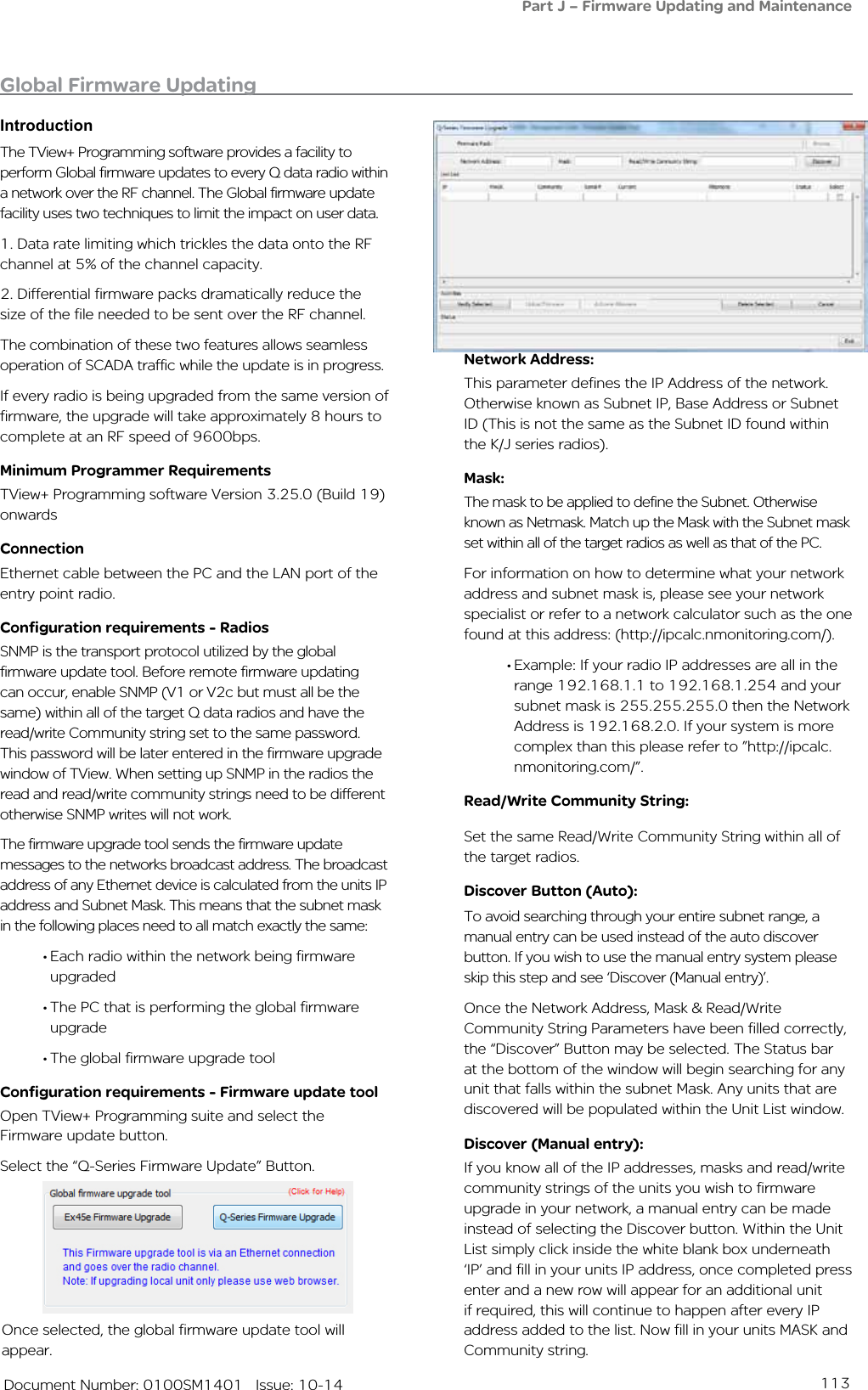
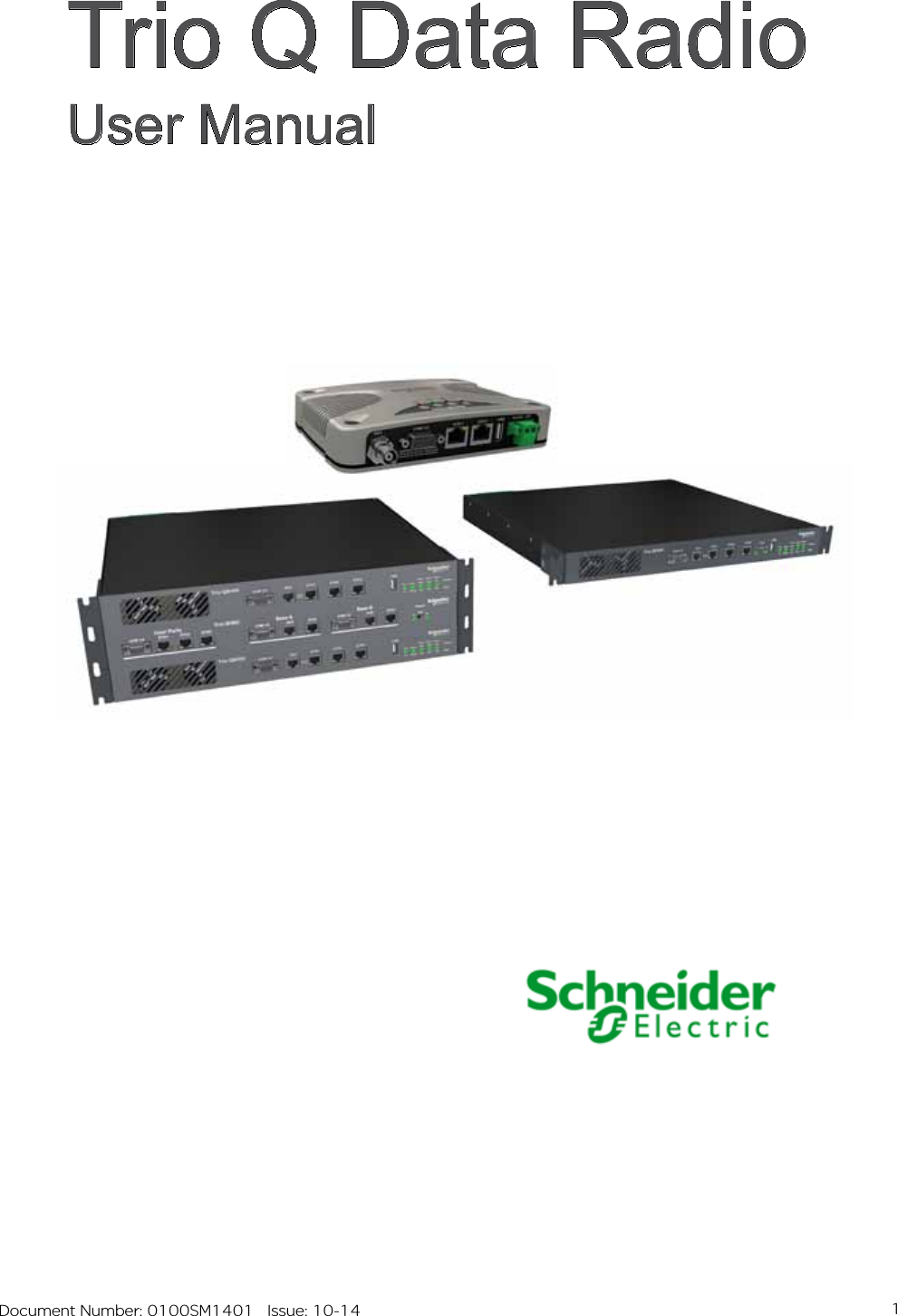
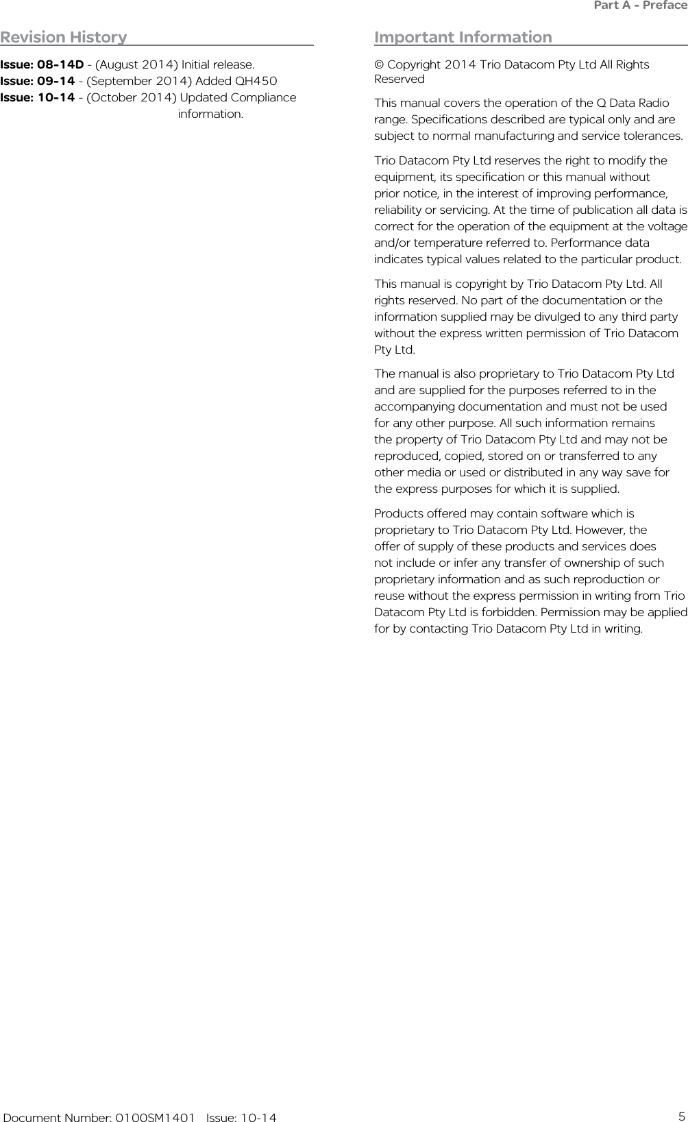
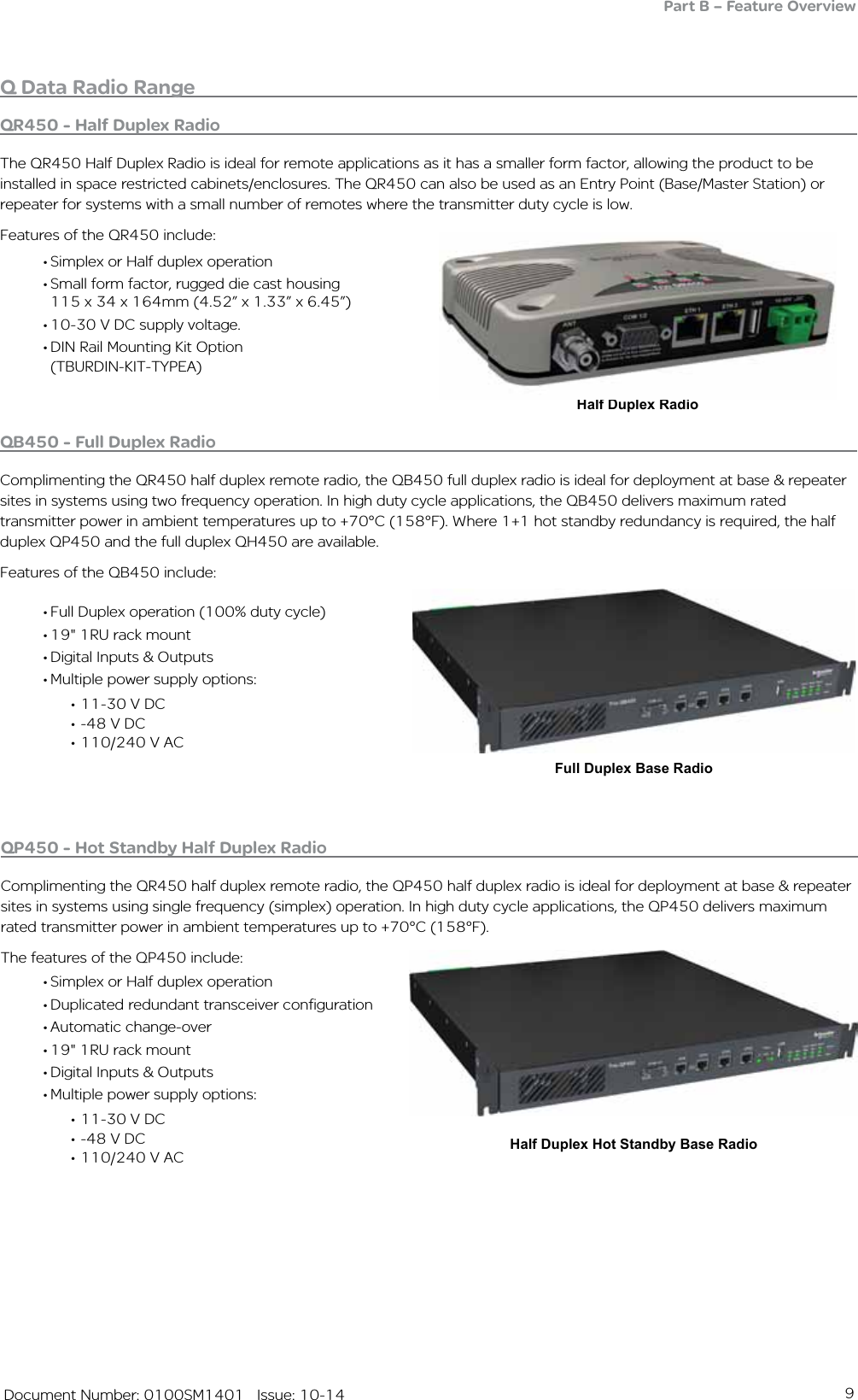
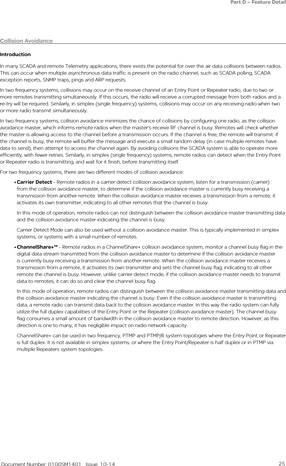
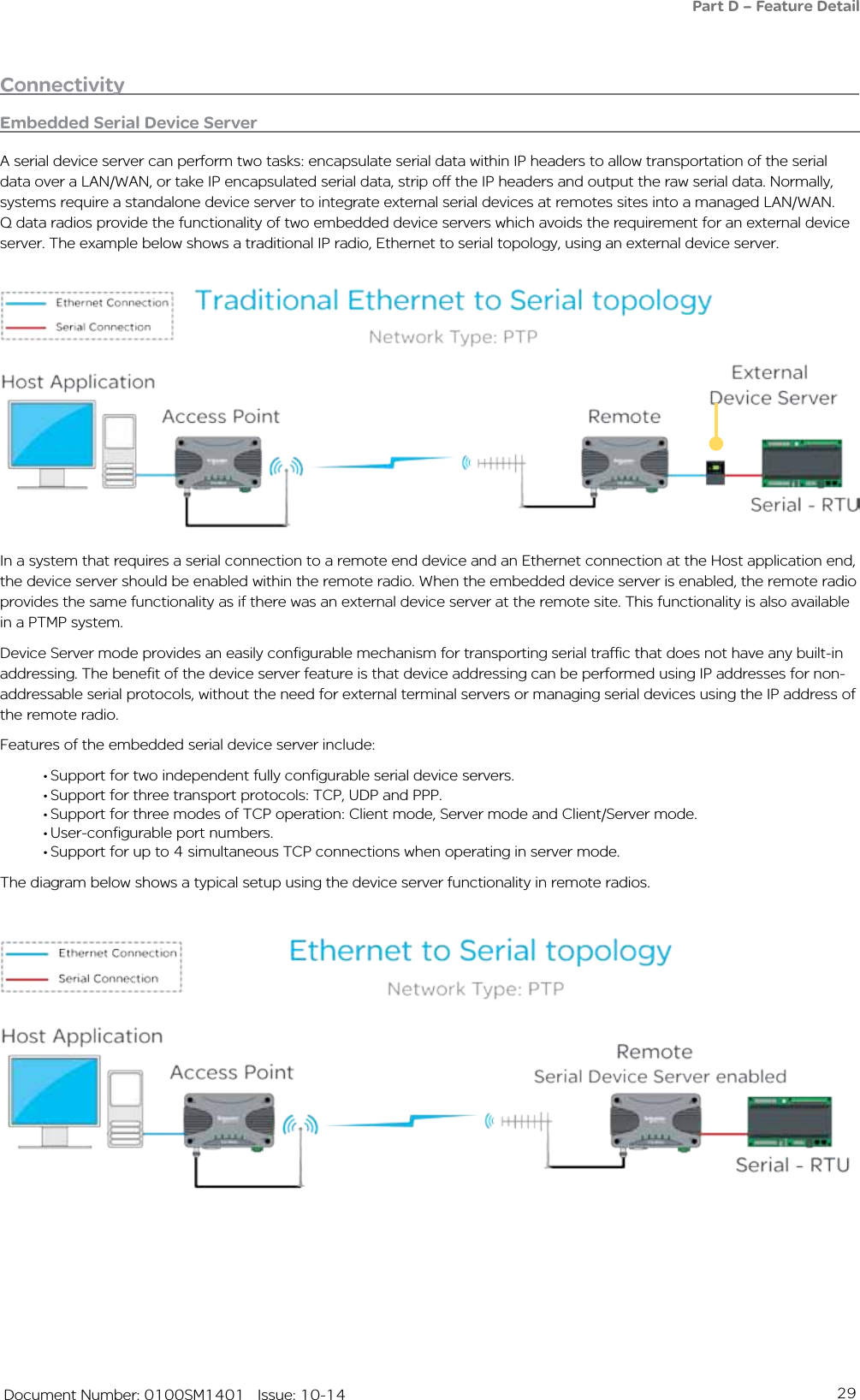
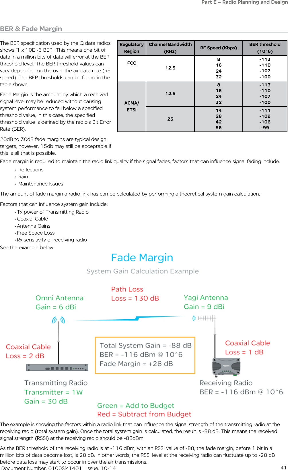
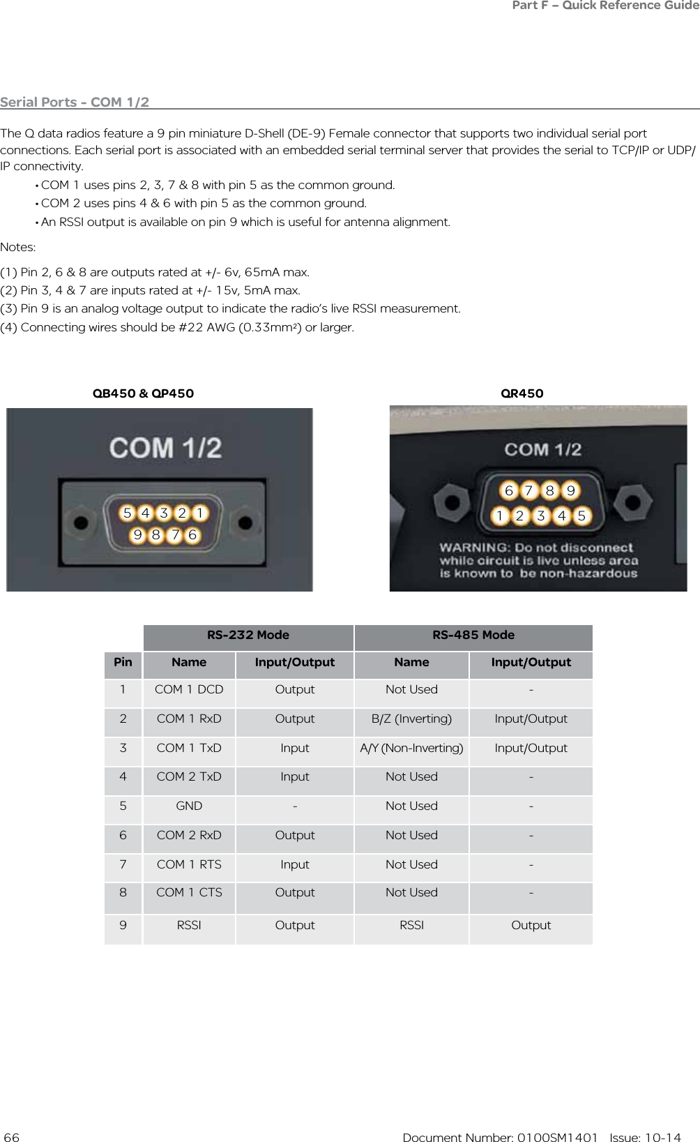
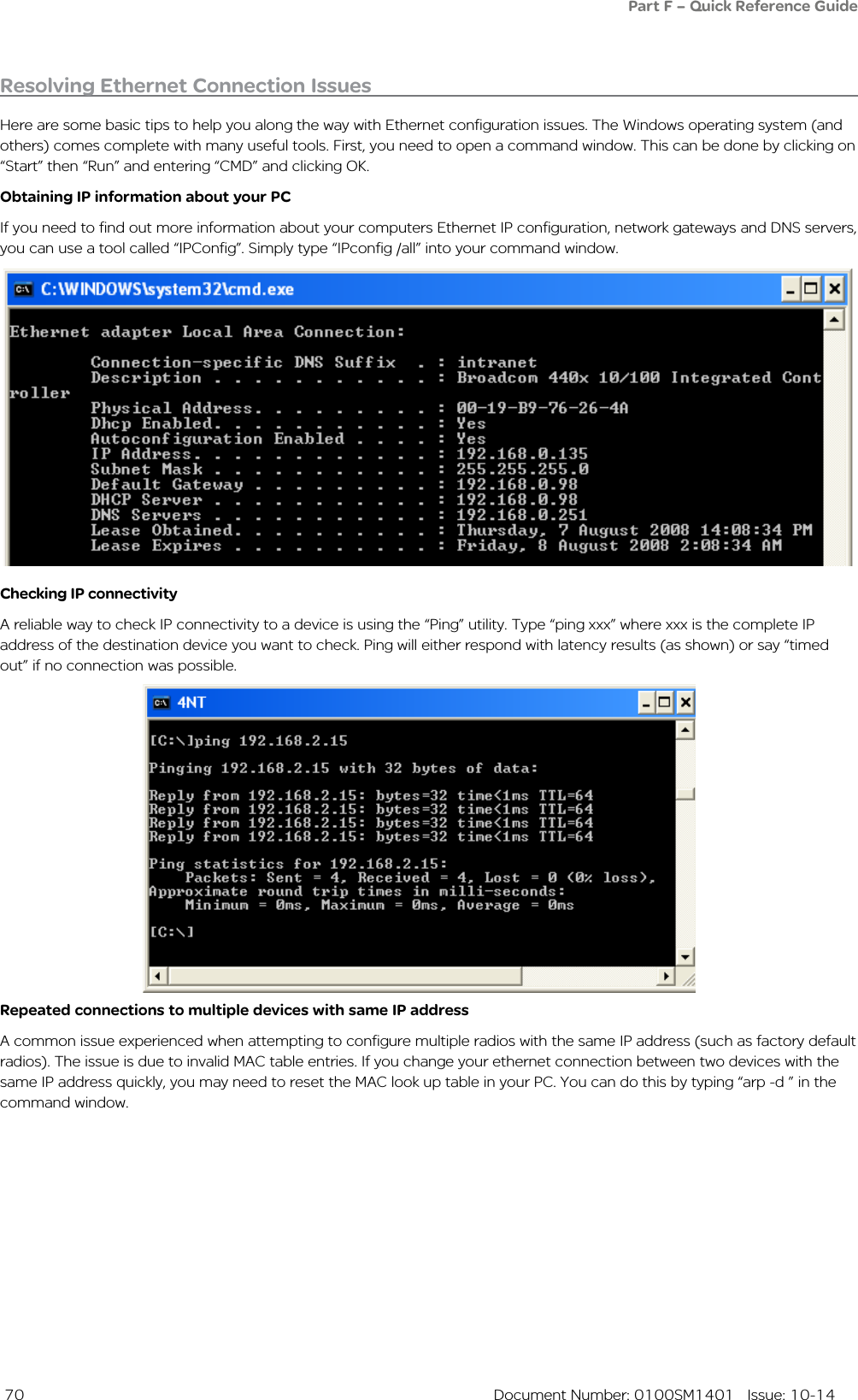
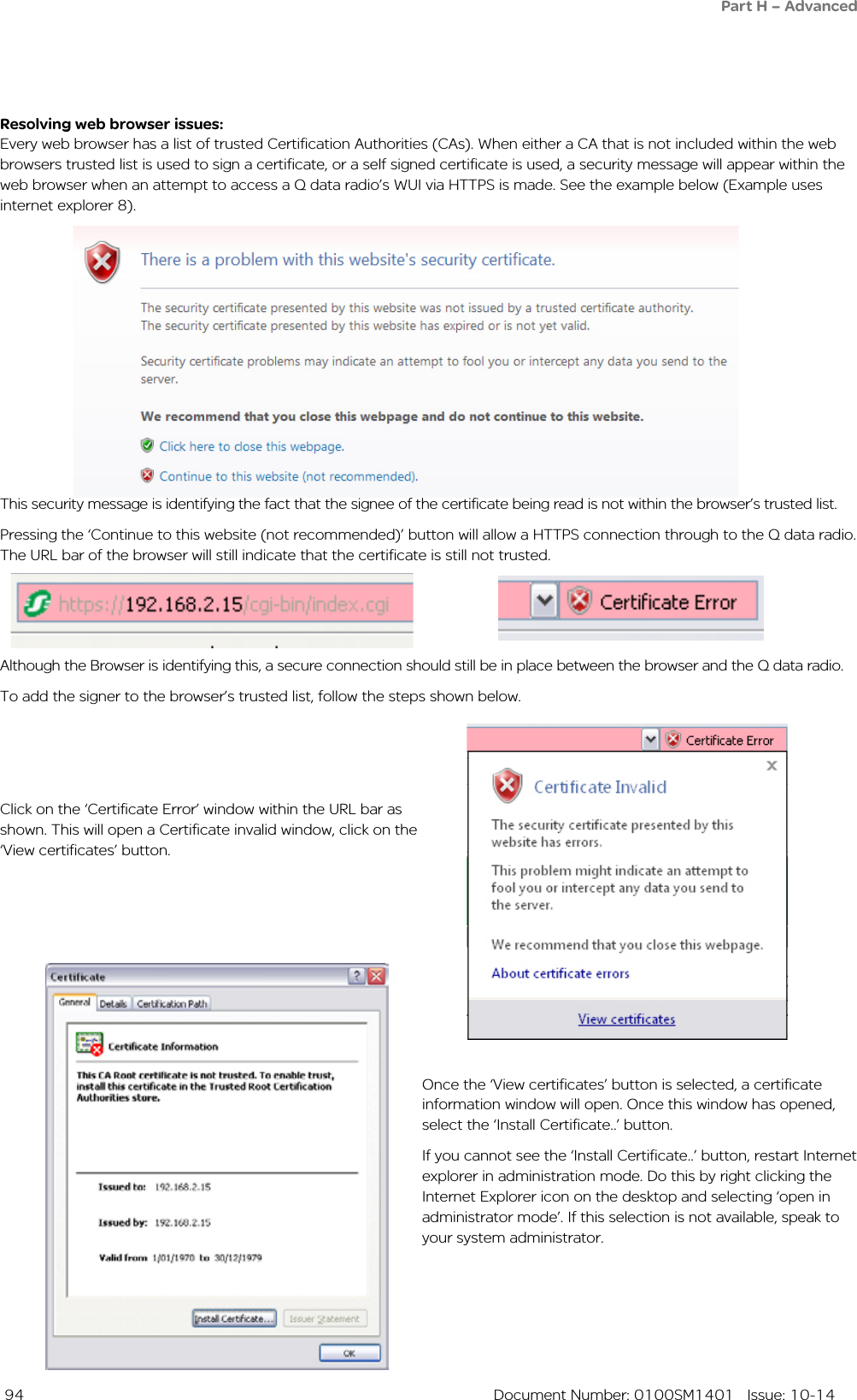
![47 Document Number: 0100SM1401 Issue: 10-1426mm [1.02in.]34mm [1.33in.]34mm [1.34in.]58.5mm [2.3in.]70.5mm [2.77in.]10mm [0.39in.]58mm [2.28in.] 58mm [2.28in.]59mm [2.32in.]10mm [0.39in.]5mm [0.19in.]7mm [0.27in.]70.5mm [2.77in.]Part F – Quick Reference Guide34mm [1.33in.]](https://usermanual.wiki/Trio-Datacom/QB450QP450.User-Manual/User-Guide-2463749-Page-47.png)
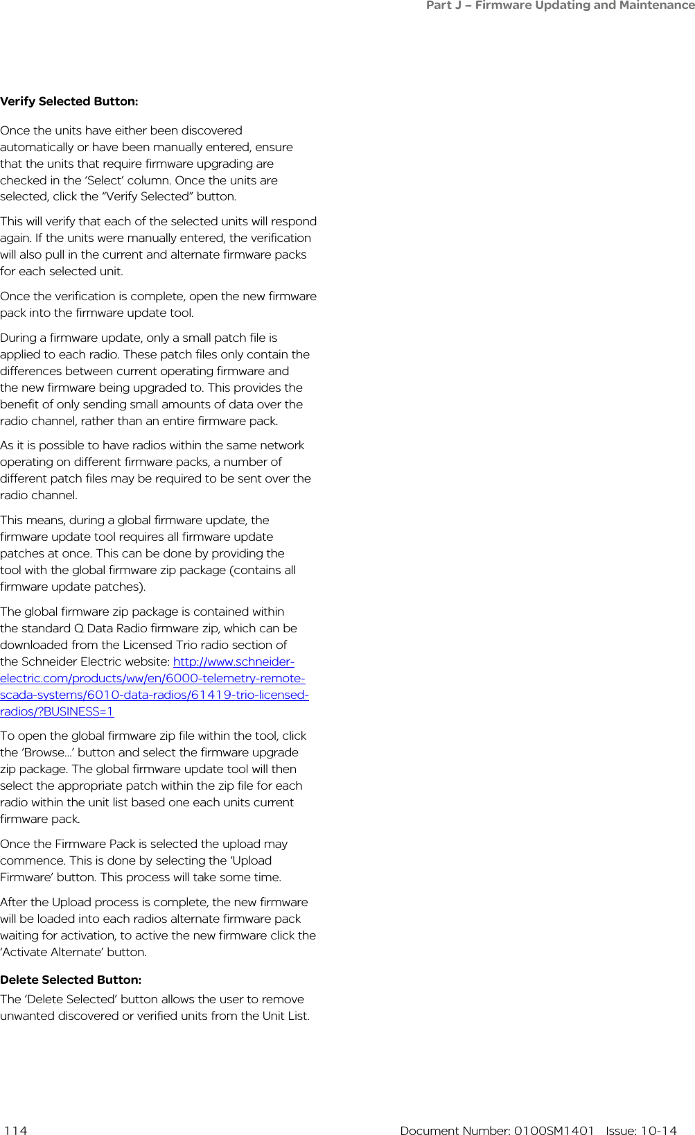
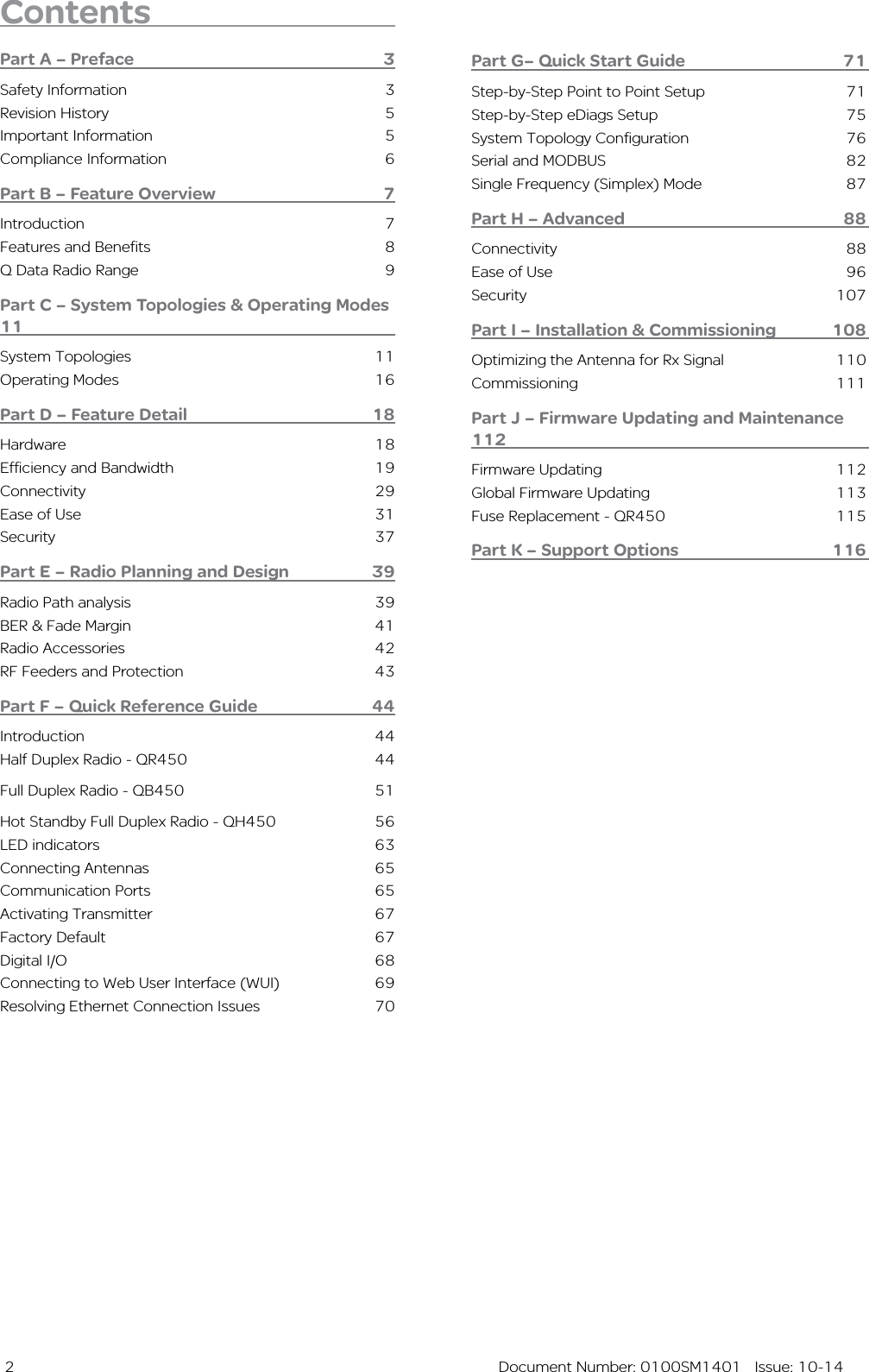
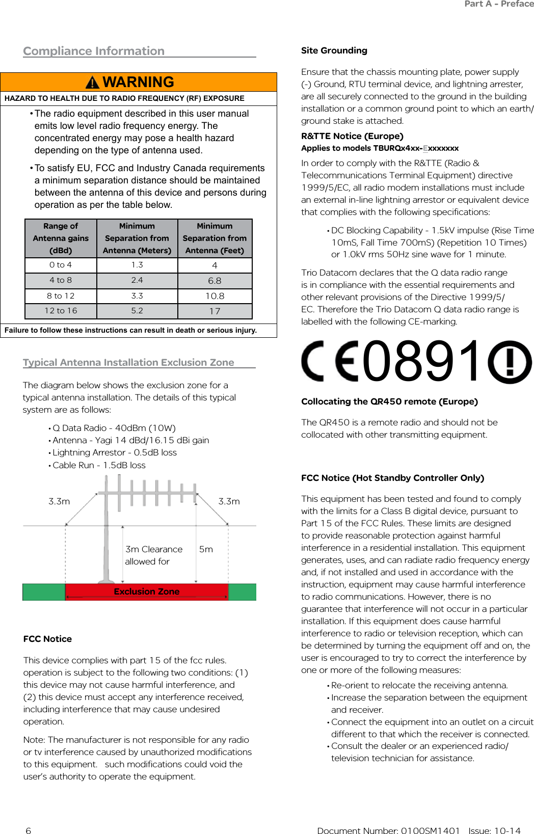
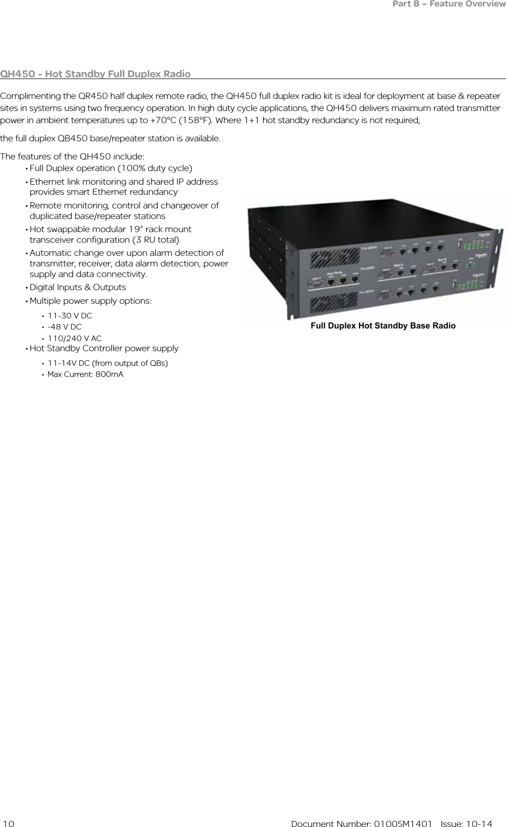
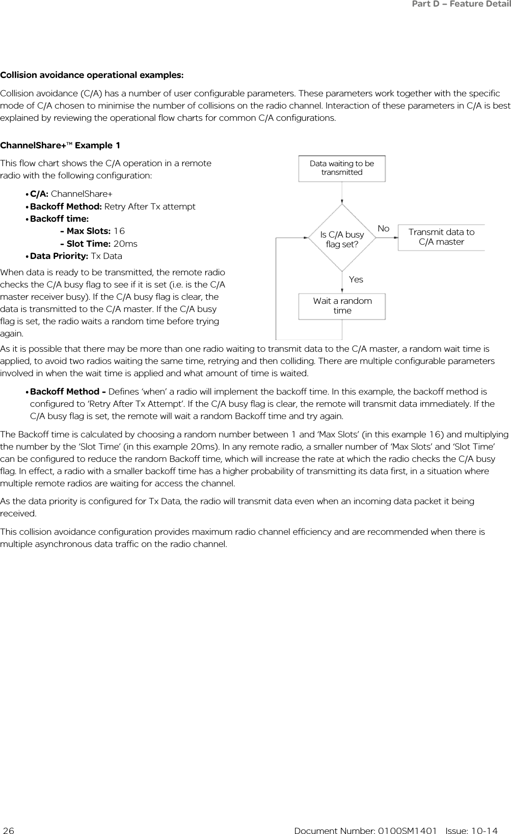
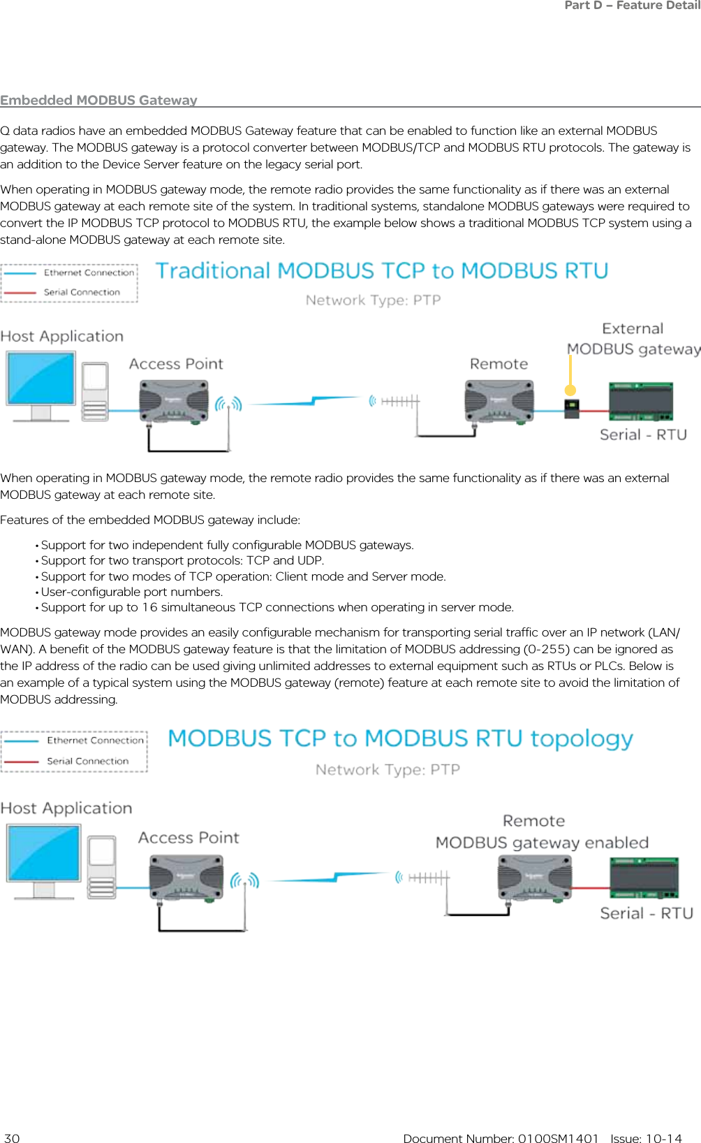
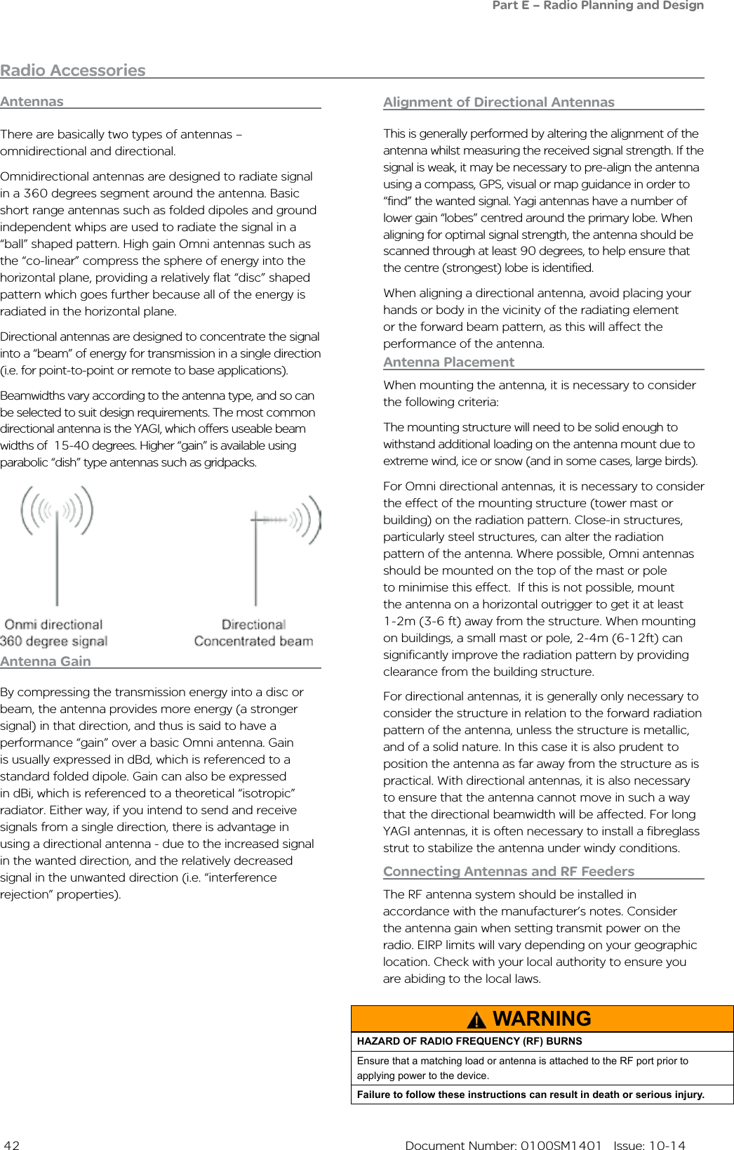
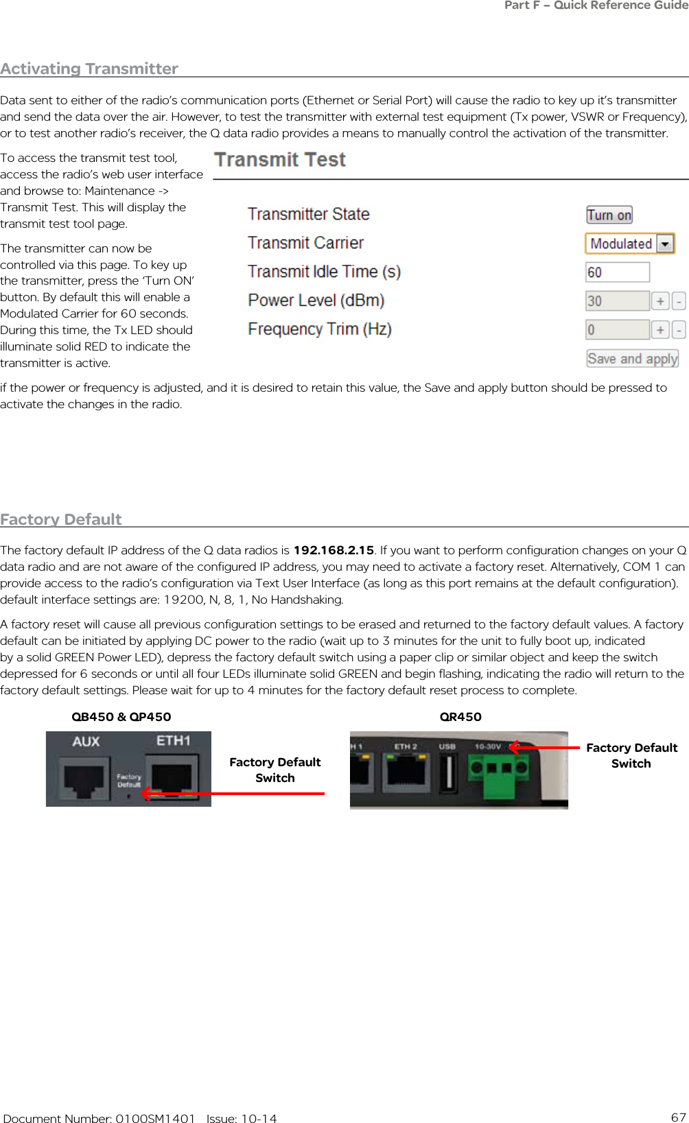
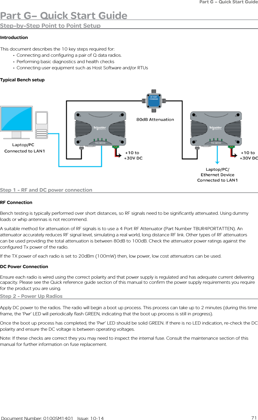
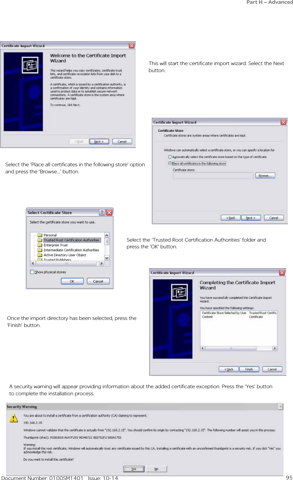
![48 Document Number: 0100SM1401 Issue: 10-14DIN rail clipThe DIN rail clip has a spring loaded latch to allow easy installation/removal of the radio device being installed.The DIN rail clip can be fitted to the DIN rail mounting bracket x5 different ways to allow as much installation flexibility as possible.Rear mount DIN rail clipThe DIN rail clip can be fitted on the rear of the DIN rail mounting bracket two ways shown below.Examples of rear fitted DIN clips:OR68mm [2.68in.]16mm [0.62in.][0.62in.]16mm10mm [0.39in.]5mm [0.19in.]5mm [0.19in.]44mm [1.73in.][0.39in.]10mmPart F – Quick Reference Guide](https://usermanual.wiki/Trio-Datacom/QB450QP450.User-Manual/User-Guide-2463749-Page-48.png)


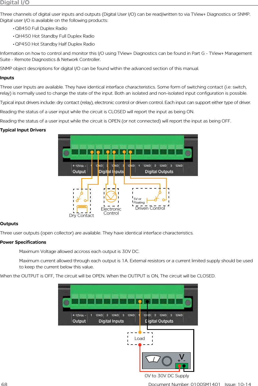
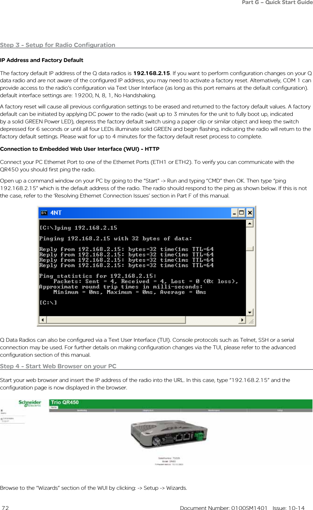
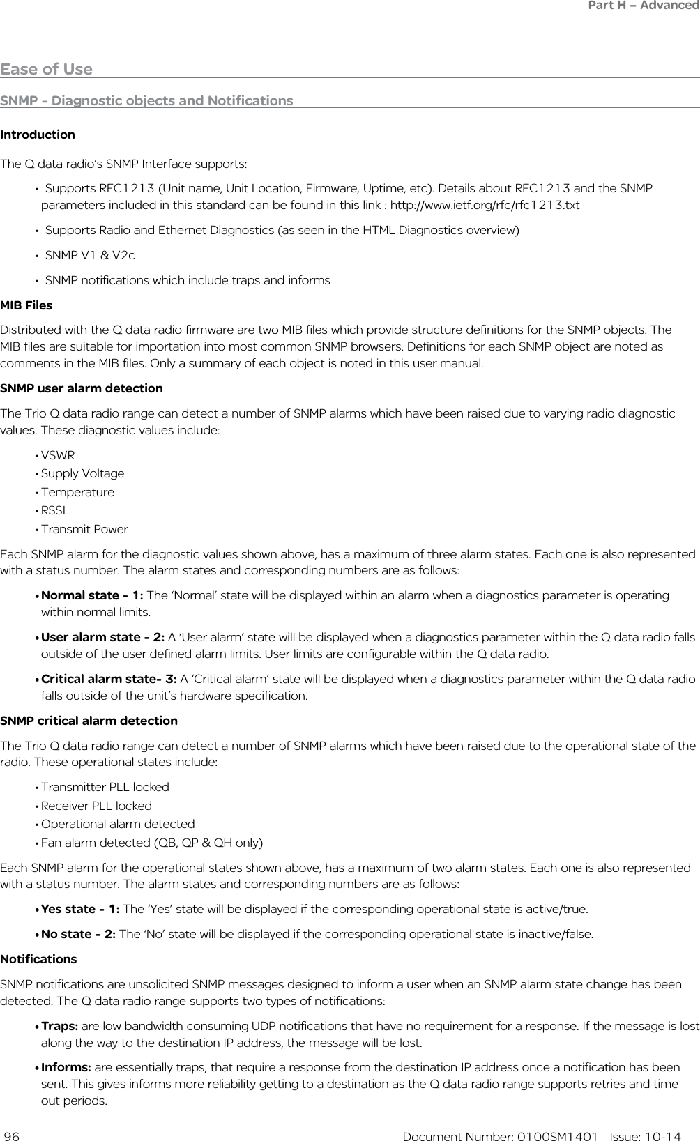
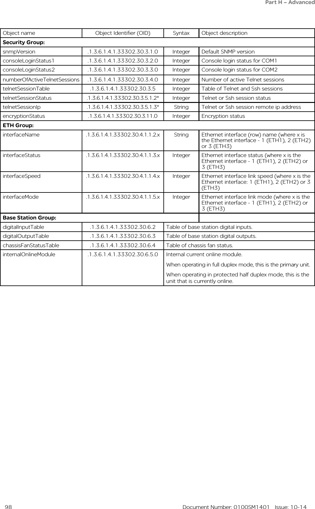
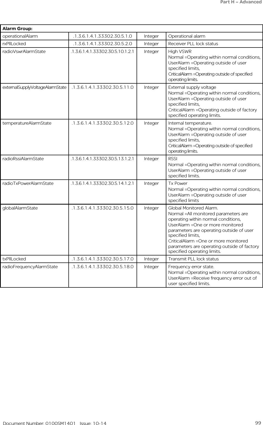
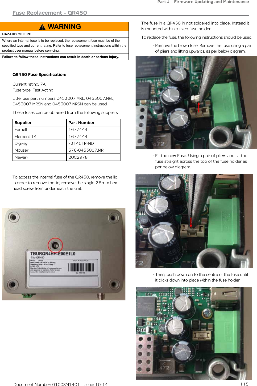
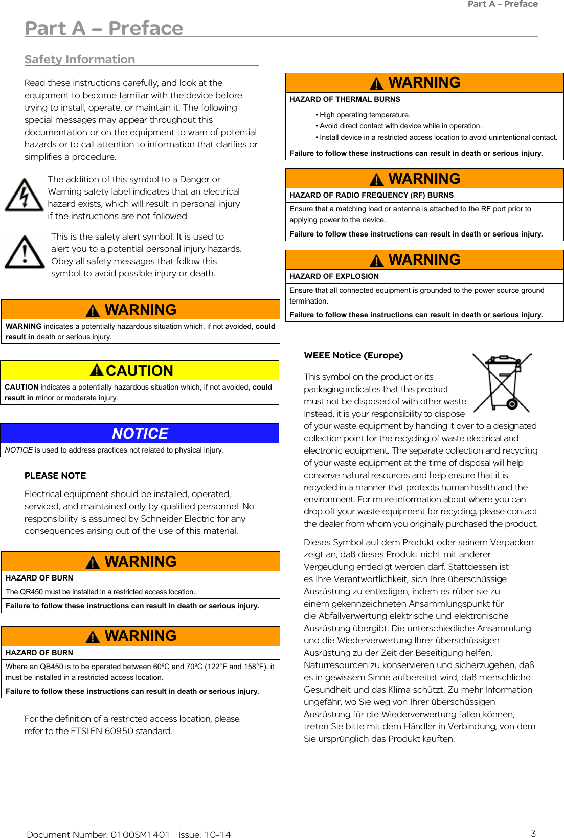
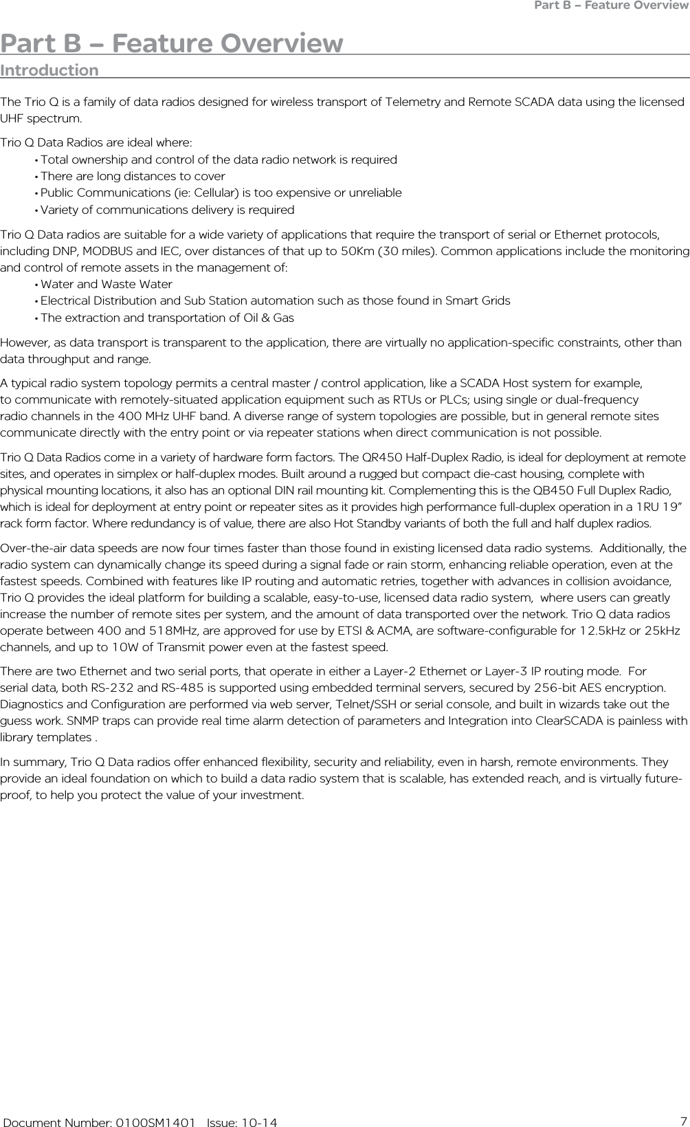
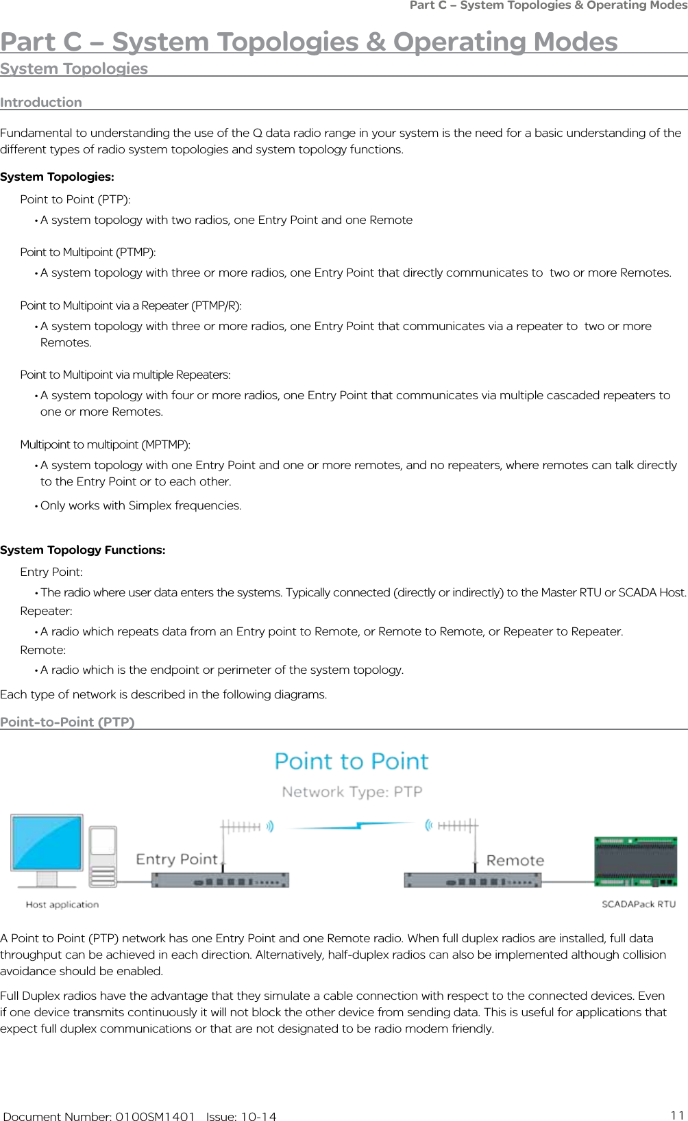
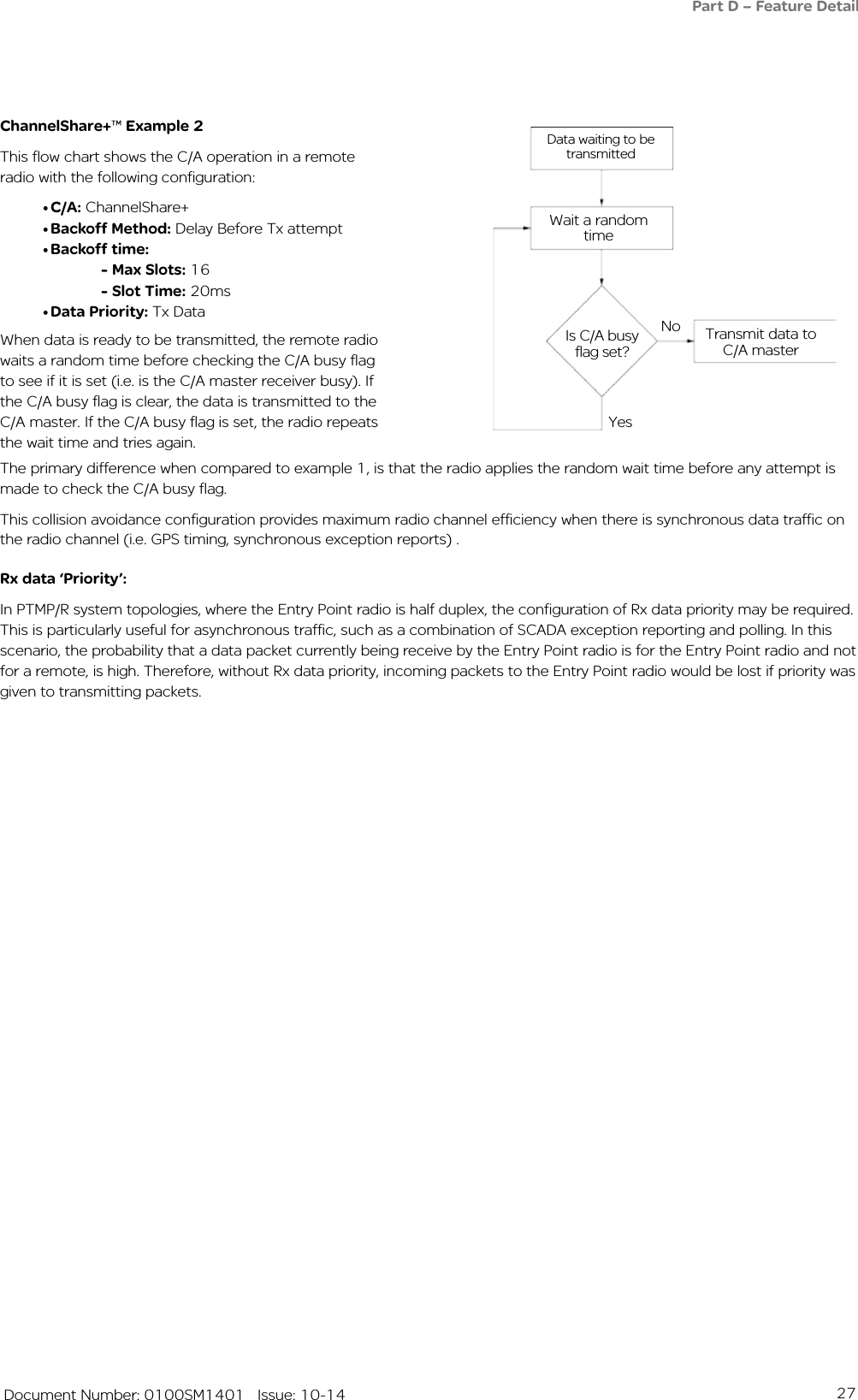
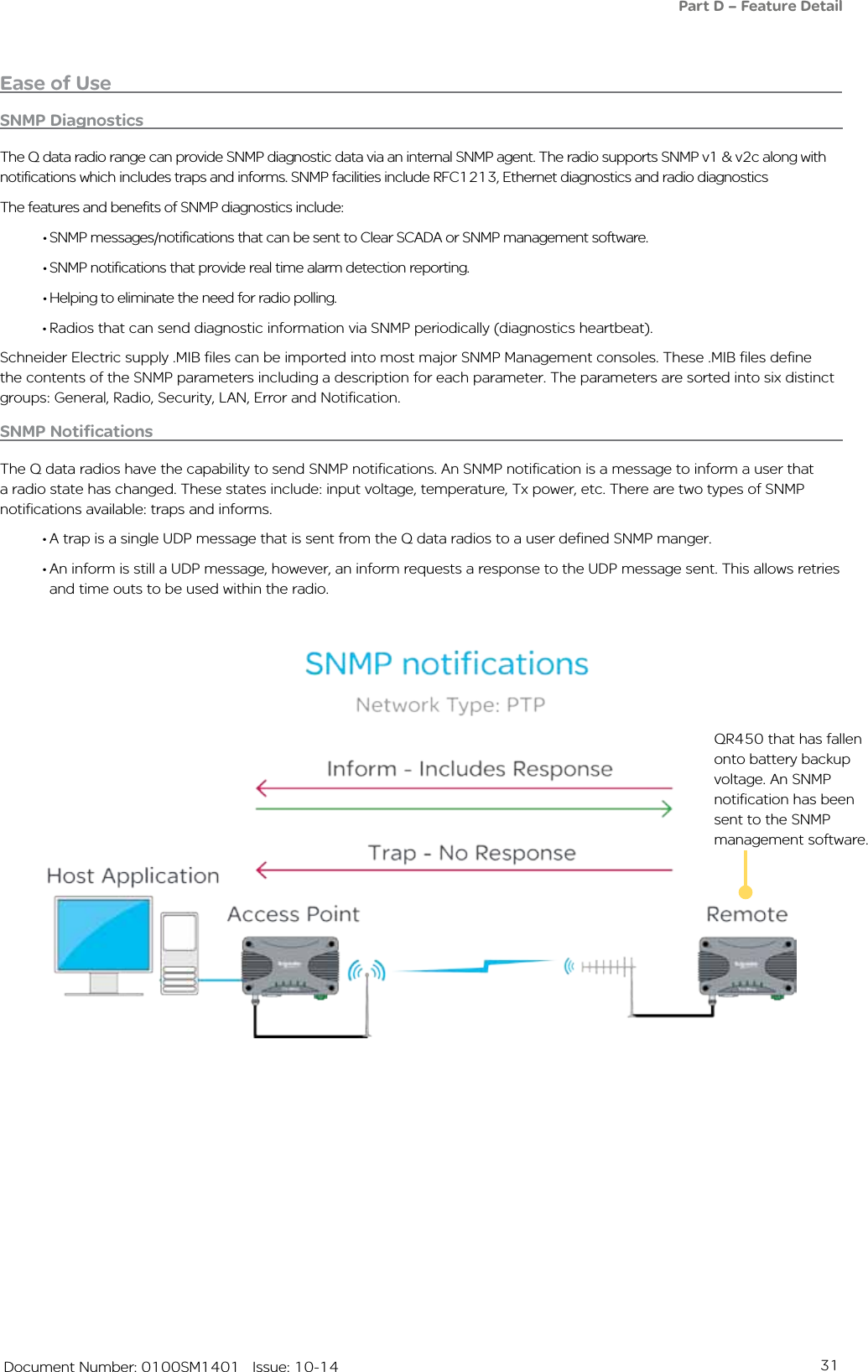
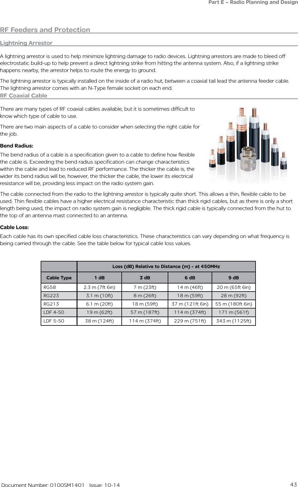
![97 Document Number: 0100SM1401 Issue: 10-14Summary of SNMP MIB Objects Supported Object name Object Identifier (OID) Syntax Object descriptionGeneral Group:serialNumber .1.3.6.1.4.1.33302.30.1.1.0 String Serial number of the Q data radiomodelNumber .1.3.6.1.4.1.33302.30.1.2.0 String Model number of the Q data radiohardwareRevision .1.3.6.1.4.1.33302.30.1.3.0 String Hardware revision of the Q data radiofirmwareRevision .1.3.6.1.4.1.33302.30.1.5.0 String The firmware revision the Q data radiodate .1.3.6.1.4.1.33302.30.1.6.0 String The date as reported by the Q data radiotime .1.3.6.1.4.1.33302.30.1.7.0 String The time as reported by the Q data radioutcTimeOffset .1.3.6.1.4.1.33302.30.1.8.0 String Time offset from UTC for the Q data radio’s local time zoneupTime .1.3.6.1.4.1.33302.30.1.9.0 String The uptime of the Q data radioprimaryNtpServer .1.3.6.1.4.1.33302.30.1.10.0 String Primary Network Time Protocol (NTP) domain namecpuLoad .1.3.6.1.4.1.33302.30.1.11.0 Integer Average CPU utilisation (%) for the past 15 minutessupplyVoltage .1.3.6.1.4.1.33302.30.1.12.0 Integer Supply Voltage of the Q data radio in mVtemperatureC .1.3.6.1.4.1.33302.30.1.13.1.3.1 Integer The internal temperature of the Q data radio (degrees C)temperatureF .1.3.6.1.4.1.33302.30.1.13.1.4.1 Integer The internal temperature of the Q data radio (degrees F)ipAddress .1.3.6.1.4.1.33302.30.1.15.0 String The IP address of the Q data radio.Radio Group:radioReceivedPackets .1.3.6.1.4.1.33302.30.2.3.0 Integer Number of packets received from over the radio linkradioTrasnmittedPackets .1.3.6.1.4.1.33302.30.2.4.0 Integer Number of packets transmitted over the radio linkradioForwardPower .1.3.6.1.4.1.33302.30.2.5.1.2.1 Integer Level of transmit power (dBm)radioReversePower .1.3.6.1.4.1.33302.30.2.6.1.2.1 Integer Level of reverse power (dBm)radioVswr .1.3.6.1.4.1.33302.30.2.7.1.2.1 Integer VSWRradioRssiValue .1.3.6.1.4.1.33302.30.2.8.1.2.1 Integer Radio RSSI value (dBm)radioDataRate .1.3.6.1.4.1.33302.30.2.15.0 Integer The over-the-air data rate of the Q data radio.[Dynamic(0), 8000bps(1), 14000bps(2), 16000bps(3), 24000bps(4), 28000bps(5), 32000bps(6), 42000bps(7), 56000bps(8)]txFrequency .1.3.6.1.4.1.33302.30.2.18.0 Integer Radio’s transmit frequency (Hz).rxFrequency .1.3.6.1.4.1.33302.30.2.19.0 Integer Radio’s receive frequency (Hz).muteThreshold .1.3.6.1.4.1.33302.30.2.20.0 Integer Radio’s mute threshold (dBm).rxGoodFrameCount .1.3.6.1.4.1.33302.30.2.23.0 Integer Good frames received.rxGoodByteCount .1.3.6.1.4.1.33302.30.2.24.0 Integer Good bytes received.rxBadFrameCount .1.3.6.1.4.1.33302.30.2.25.0 Integer Bad frames received.rxAverageGoodFrameSize .1.3.6.1.4.1.33302.30.2.26.0 Integer Average received good frame size.rxAverageFrameRate .1.3.6.1.4.1.33302.30.2.27.0 Integer Average receive frame rate.rxChannelOccupancy .1.3.6.1.4.1.33302.30.2.28.0 Integer Receive channel occupancy.rxSlidingChannelOccupancy .1.3.6.1.4.1.33302.30.2.29.0 Integer Sliding channel occupancy.txByteCount .1.3.6.1.4.1.33302.30.2.31.0 Integer Transmitted byte counter.txFrameCount .1.3.6.1.4.1.33302.30.2.32.0 Integer Transmit frame count.txAverageFrameSize .1.3.6.1.4.1.33302.30.2.33.0 Integer Transmit average frame size.txAverageFrameRate .1.3.6.1.4.1.33302.30.2.34.0 Integer Transmit average frame rate.radioFrequencyError .1.3.6.1.4.1.33302.30.2.36.0 Integer Radio frequency error (Hz).Part H – Advanced](https://usermanual.wiki/Trio-Datacom/QB450QP450.User-Manual/User-Guide-2463749-Page-97.png)