United Technologies Electronic Controls BBECC01B Bryant Evolution Connex Control User Manual SYSTXCCITC 01SI
United Technologies Electronic Controls Inc. Bryant Evolution Connex Control SYSTXCCITC 01SI
Contents
- 1. Installation Manual
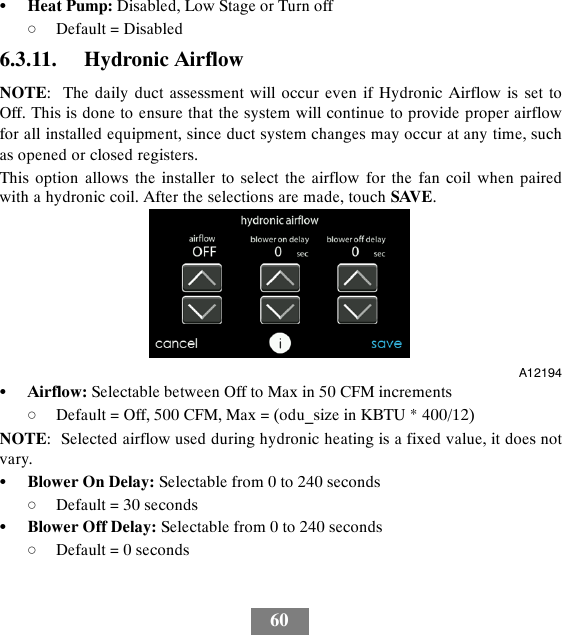
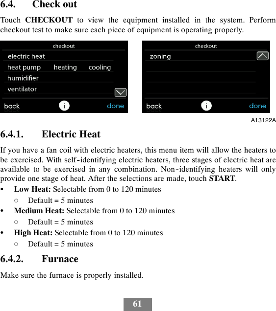
- 2. User Manual
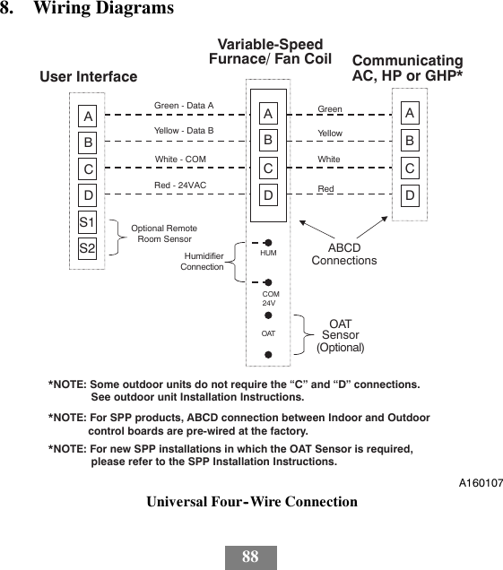
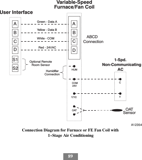
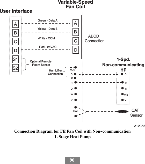
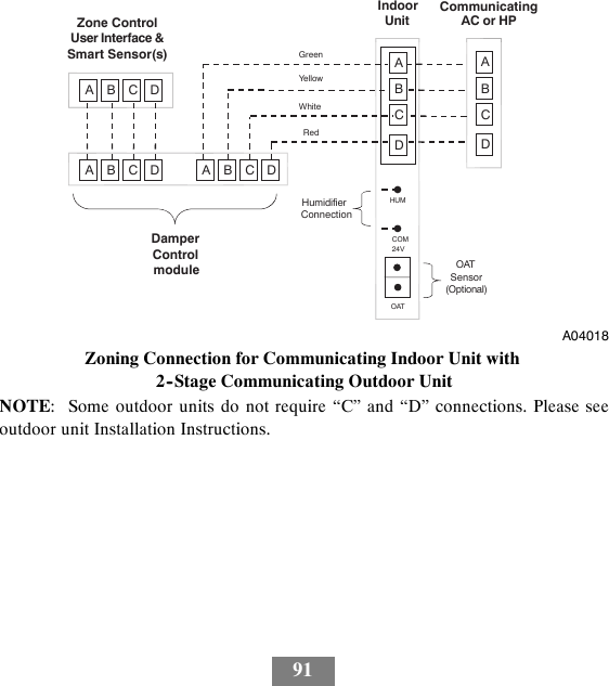
Installation Manual