Vieworks FXRD1417W X-ray Detector User Manual
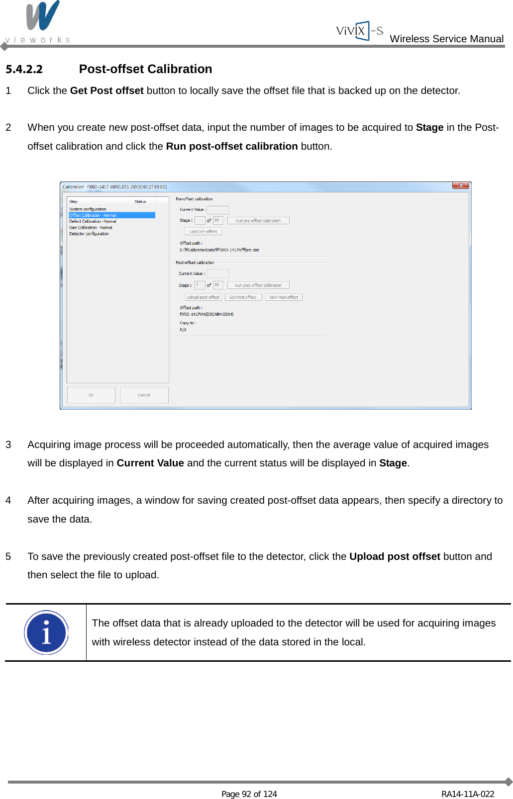
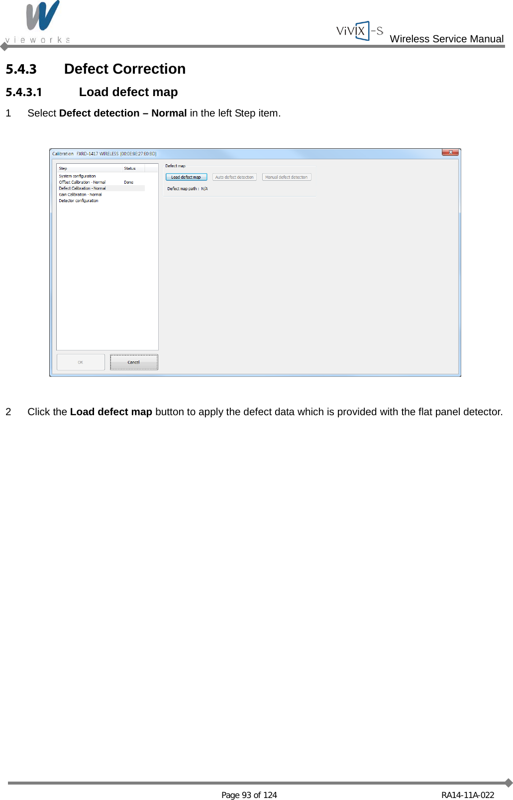
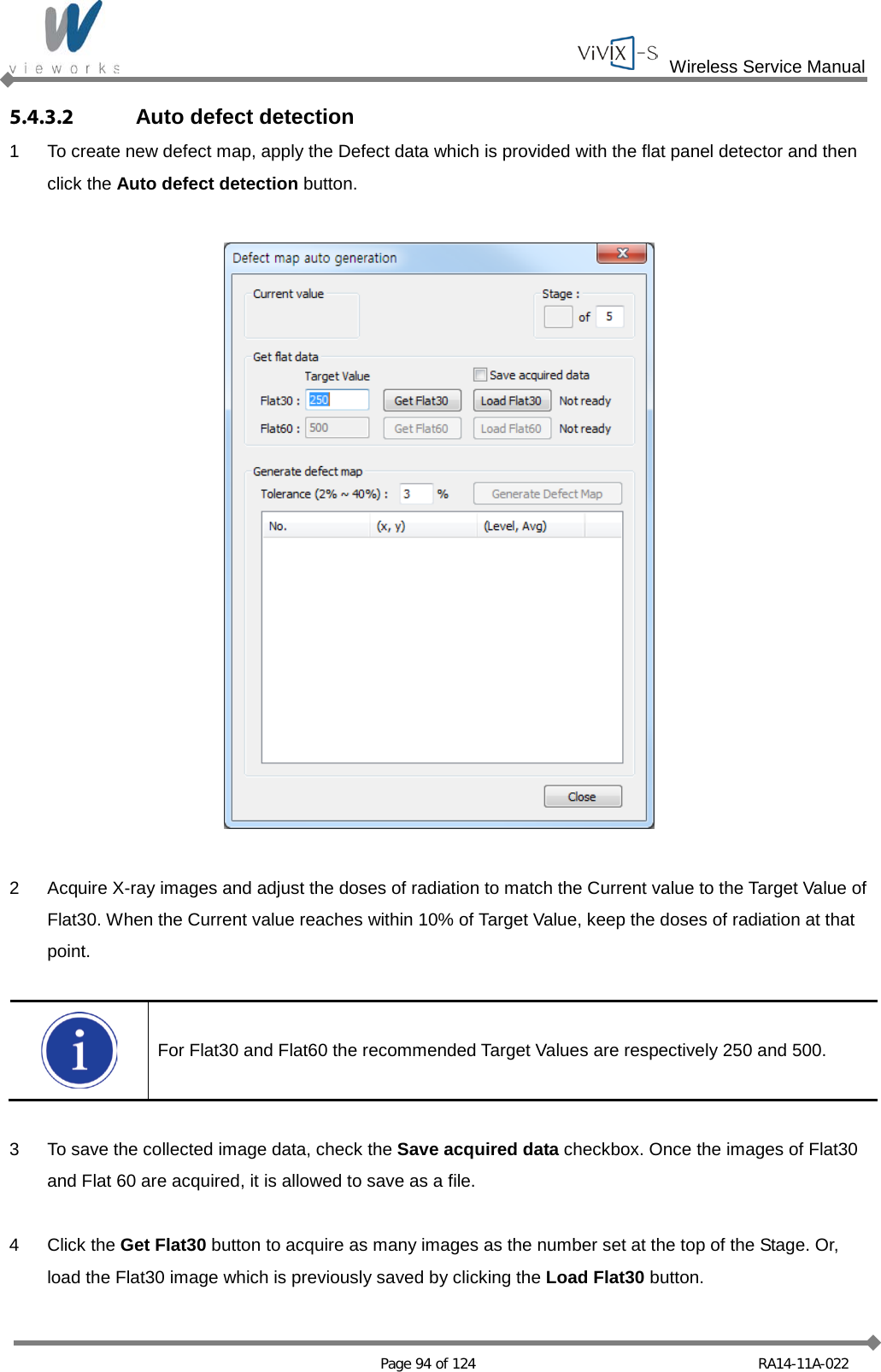
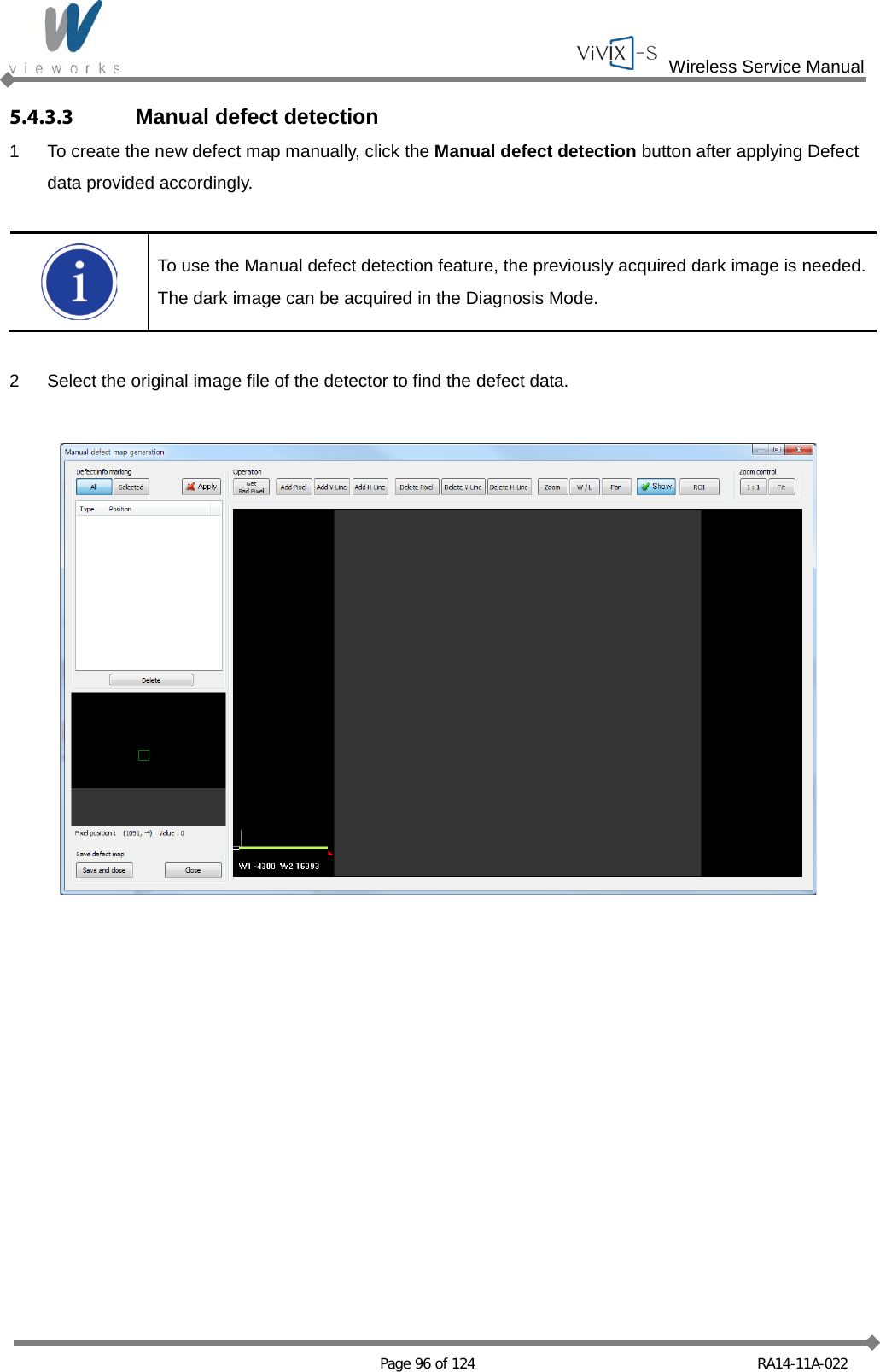
Vieworks Co., Ltd. X-ray Detector
UserManual.wiki
>
Vieworks
>
FXRD1417W User Manual
User Manual
Navigation menu
Upload a User Manual
Namespaces
Wiki Guide
HTML
PDF
Info
Views
User Manual
Discussion / Help
Navigation

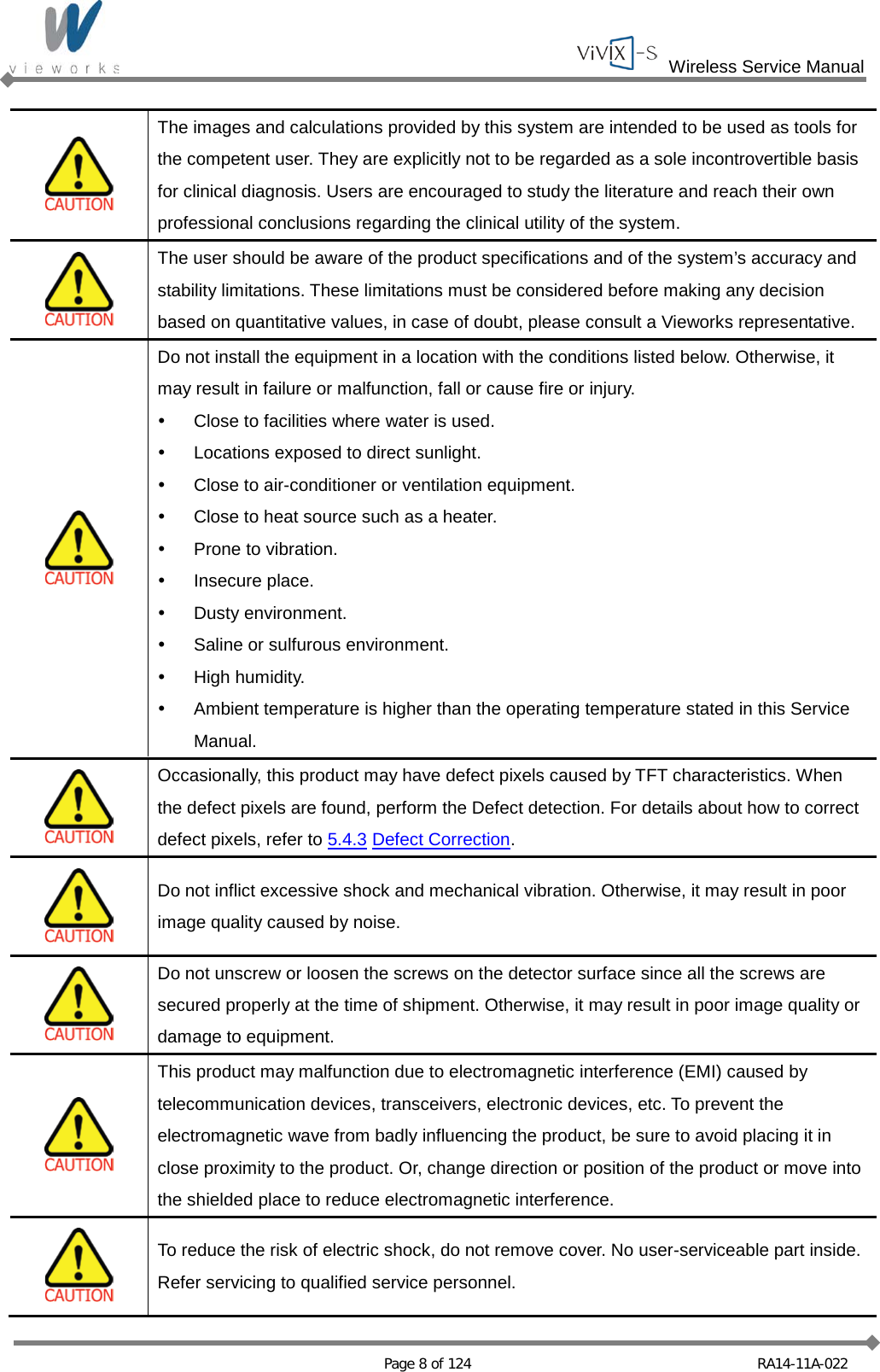

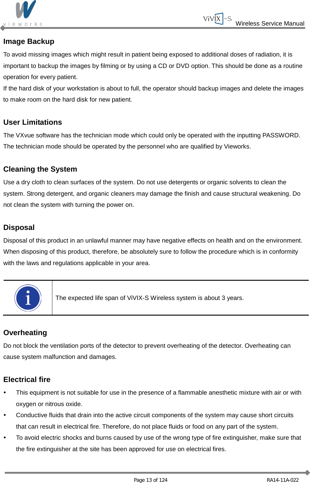

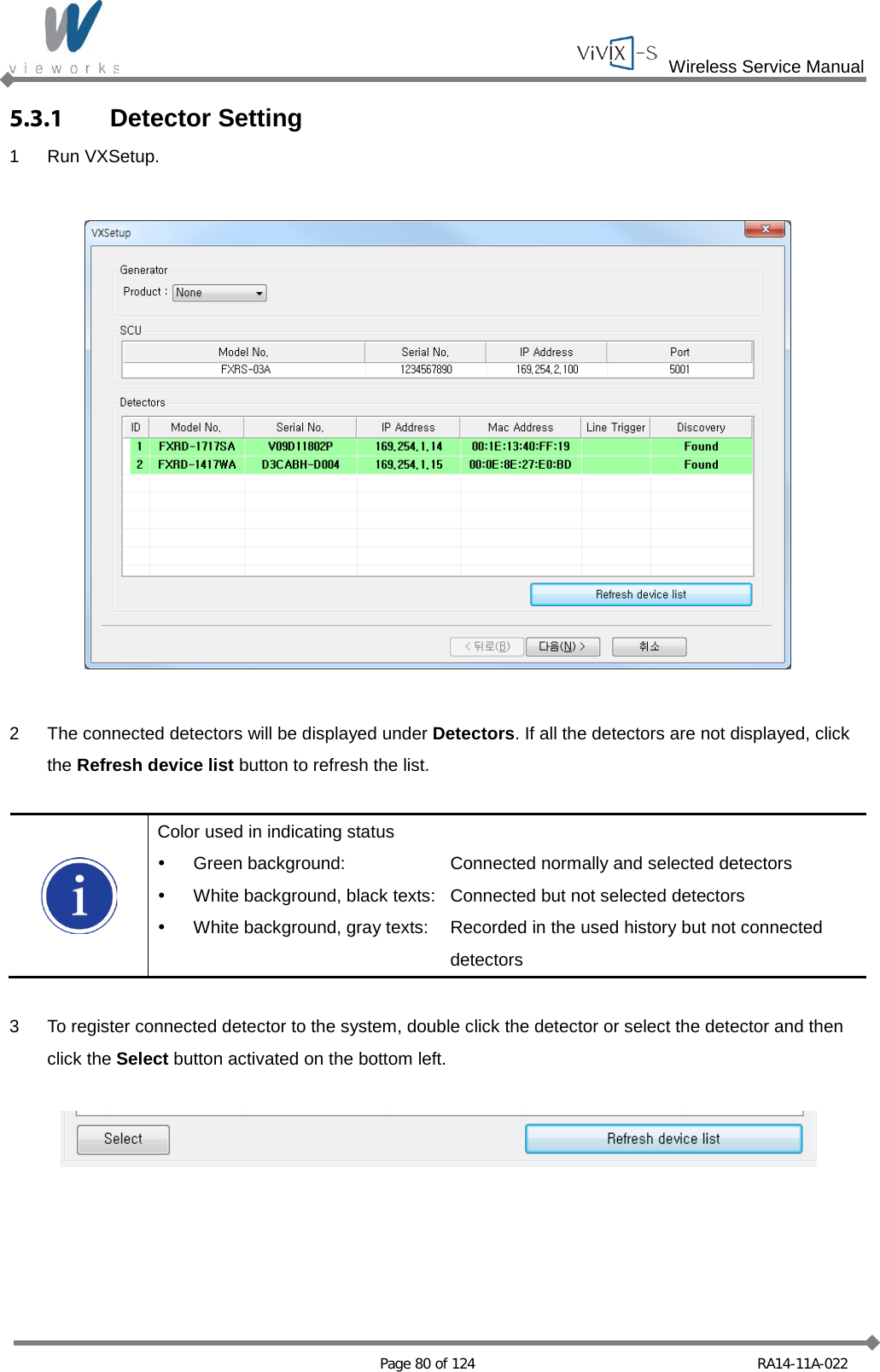
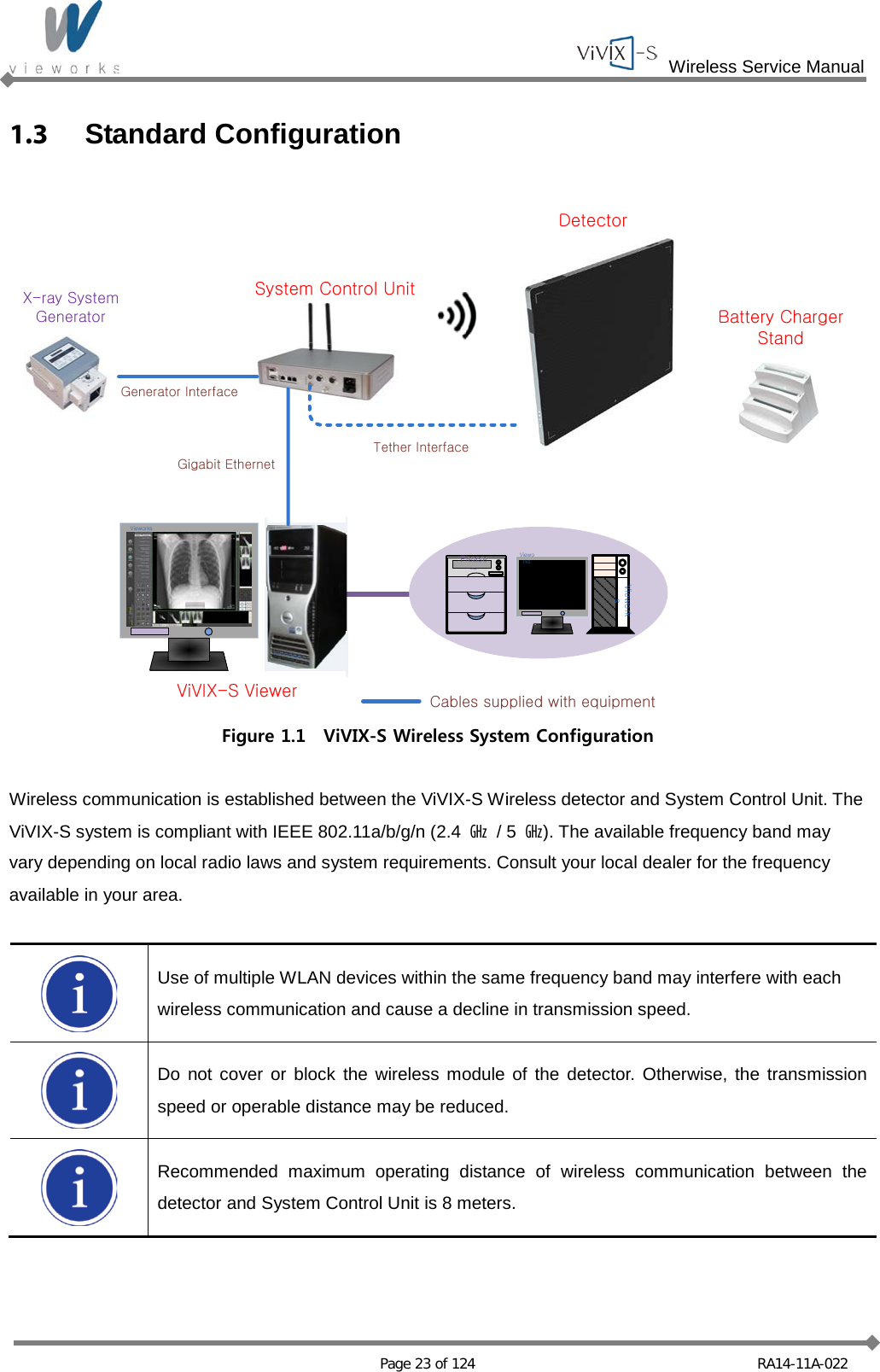
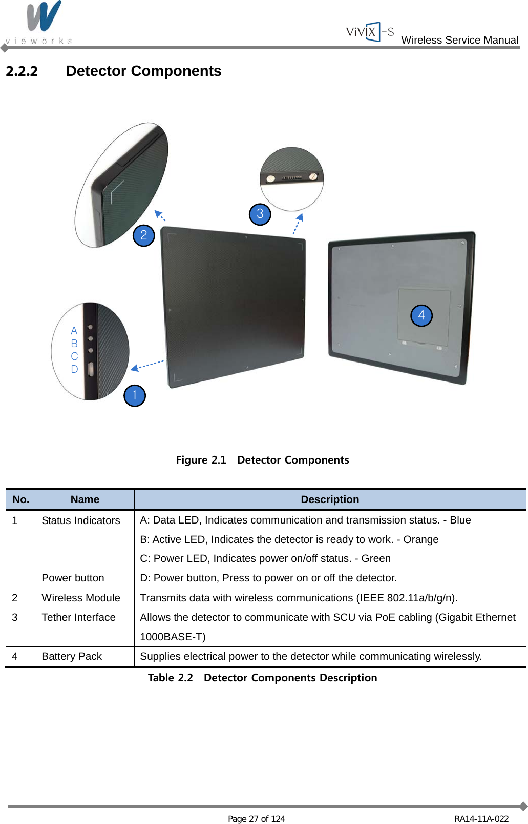
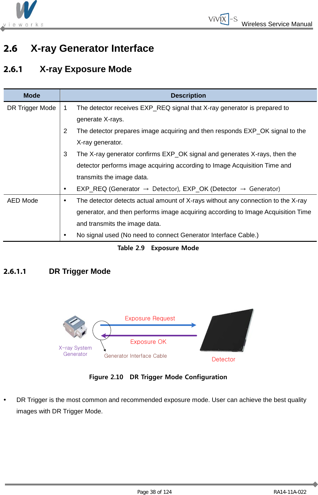
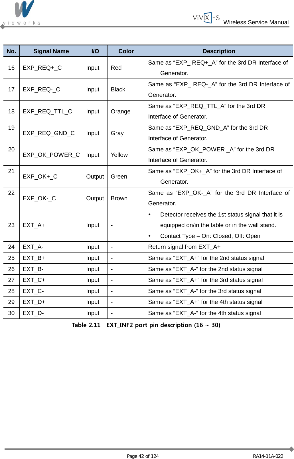
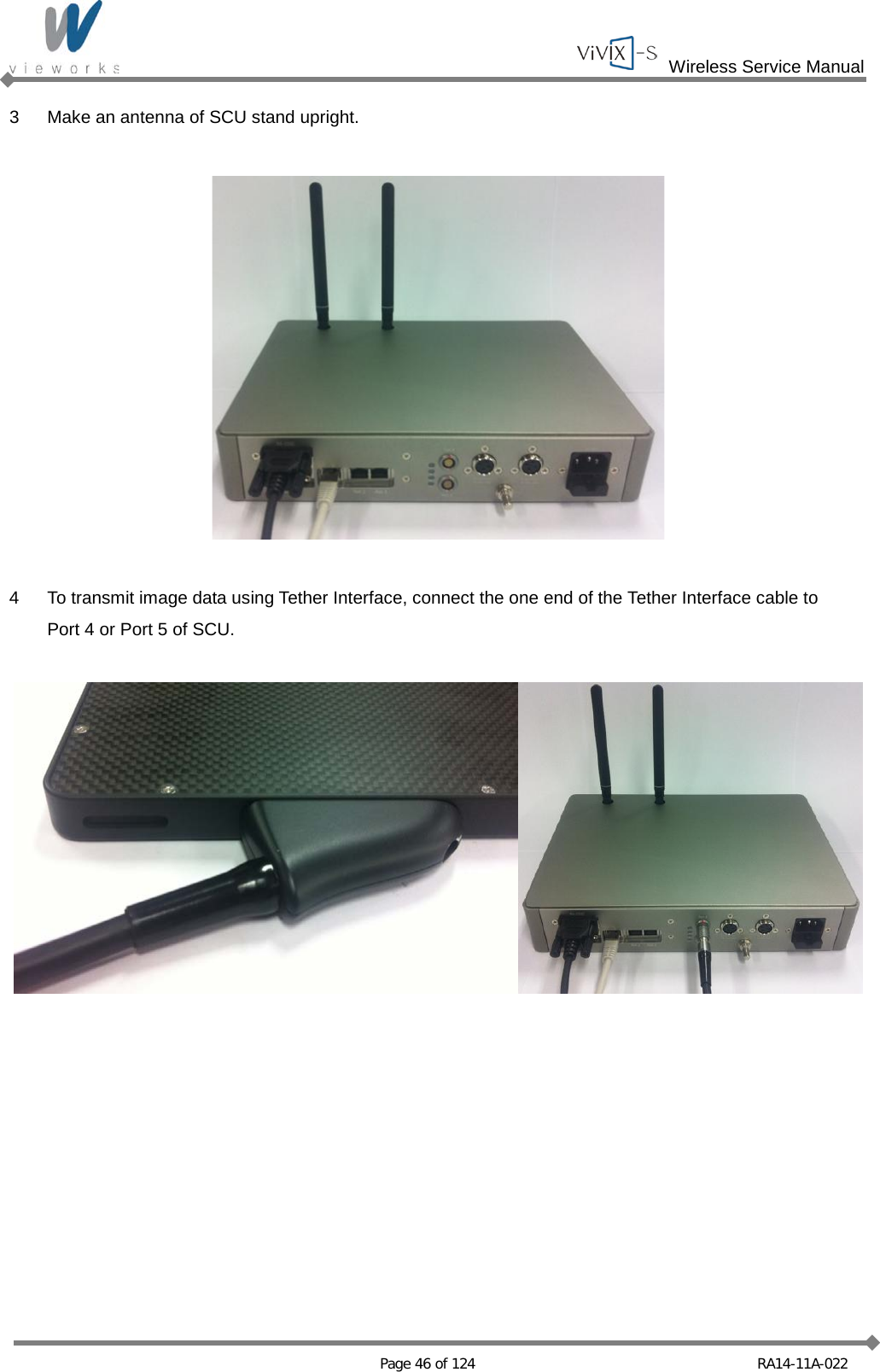
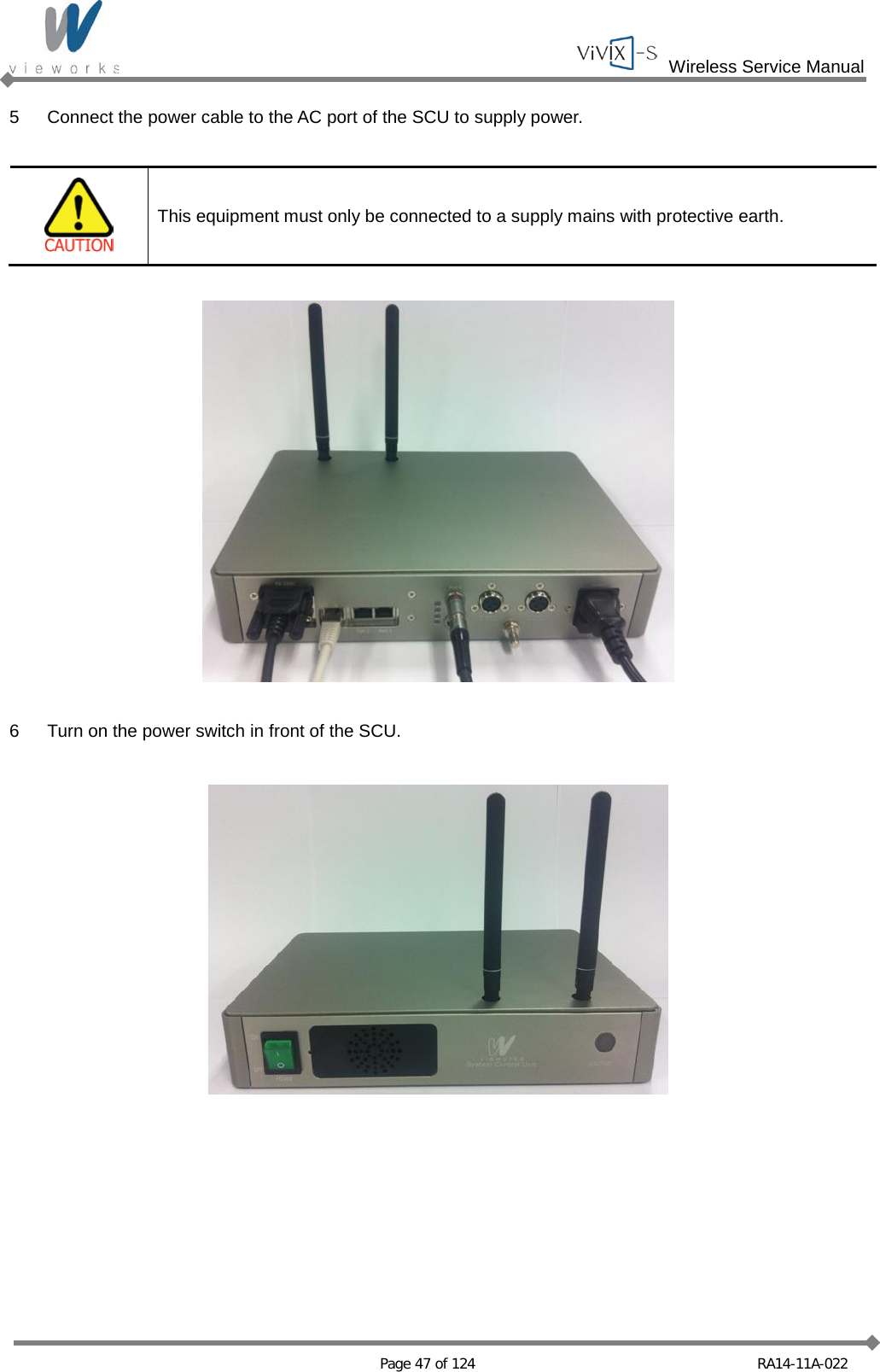
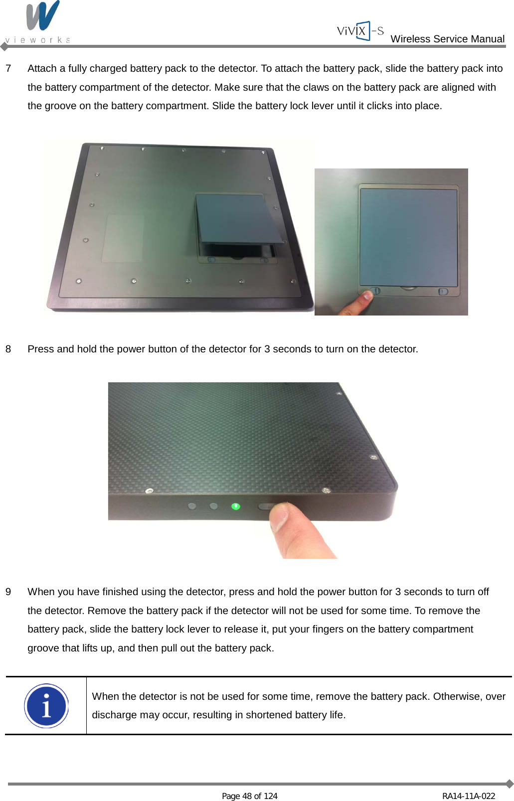
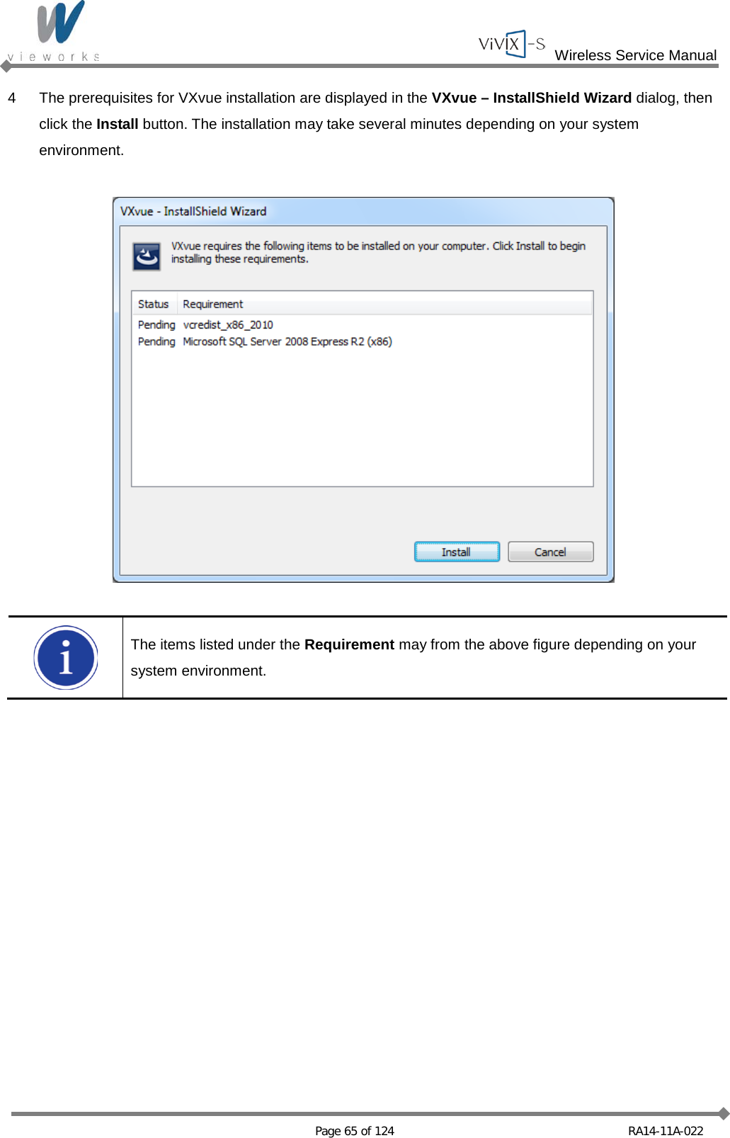
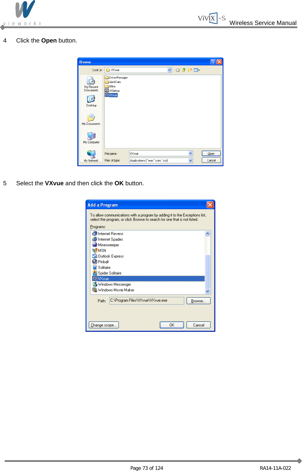
![Wireless Service Manual Page 18 of 124 RA14-11A-022 Immunity Test IEC 60601 Test Level Compliance Level Electromagnetic Environment – Guidance Conducted RF IEC 61000-4-6 Radiated RF IEC 61000-4-3 3 Vrms 150 ㎑ to 80 ㎒ 3 V/m 80 ㎒ to 2.5 ㎓ 3 Vrms 150 ㎑ to 80 ㎒ 3 V/m 80 ㎒ to 2.5 ㎓ Portable and mobile RF communications equipment should be used no closer to any part of the EUT, including cables, than the recommended separation distance calculated from the equation applicable to the frequency of the transmitter. Recommended separation distance Where P is the maximum output power rating of the transmitter in watts (W) according to the transmitter manufacturer and d is the recommended separation distance in meters (m). Field strengths from fixed RF transmitters, as determined by an electromagnetic site surveya, should be less than the compliance level in each frequency range.b Interference may occur in the vicinity of equipment marked with the following symbol: NOTE 1: At 80 ㎒ and 800 ㎒, the higher frequency range applies. NOTE 2: These guidelines may not apply in all situations. Electromagnetic propagation is affected by absorption and reflection from structures, objects and people. a Field strengths from fixed transmitters, such as base stations for radio (cellular/cordless) telephones and land mobile radios, amateur radio, AM and FM radio broadcast and TV broadcast cannot be predicted theoretically with accuracy. To assess the electromagnetic environment due to fixed RF transmitters, an electromagnetic site survey should be considered. If the measured field strength in the location in which the EUT is used exceeds the applicable RF compliance level above, the EUT should be observed to verify normal operation. If abnormal performance is observed, additional measures may be necessary, such as reorienting or relocating the EUT. b Over the frequency range 150 ㎑ to 80 ㎒, field strengths should be less than [V1] V/m.](https://usermanual.wiki/Vieworks/FXRD1417W/User-Guide-2201128-Page-18.png)
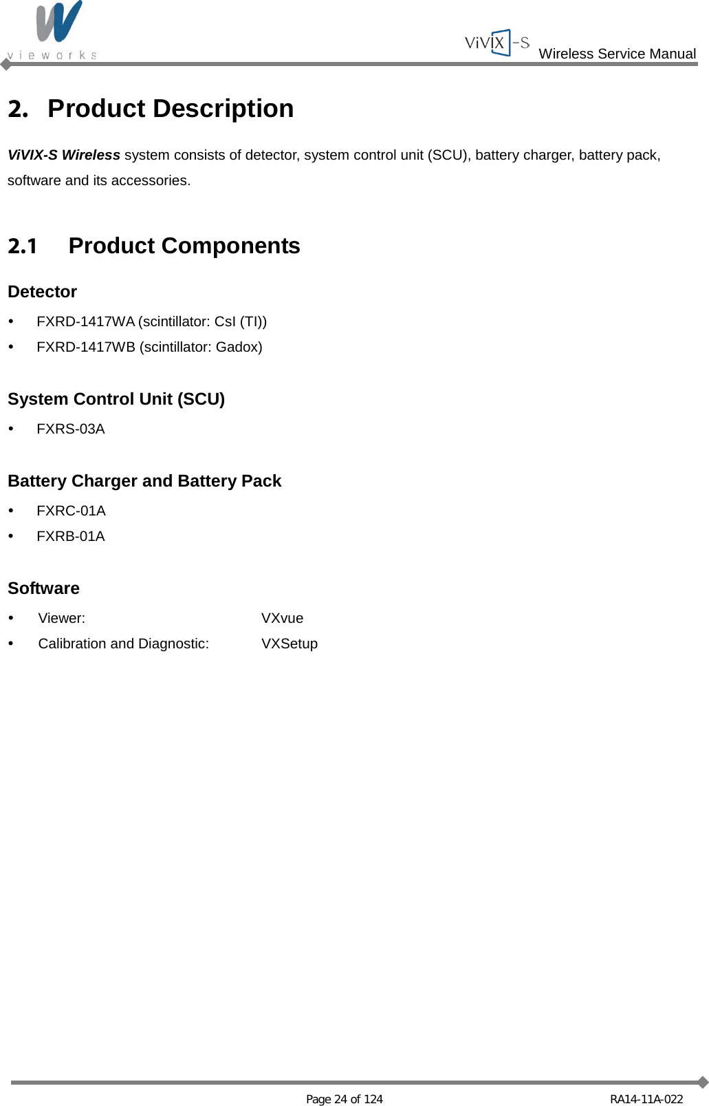
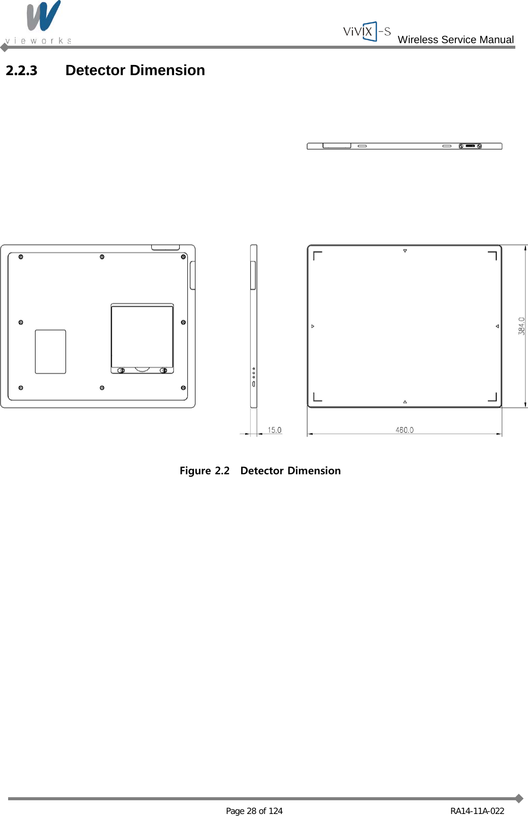


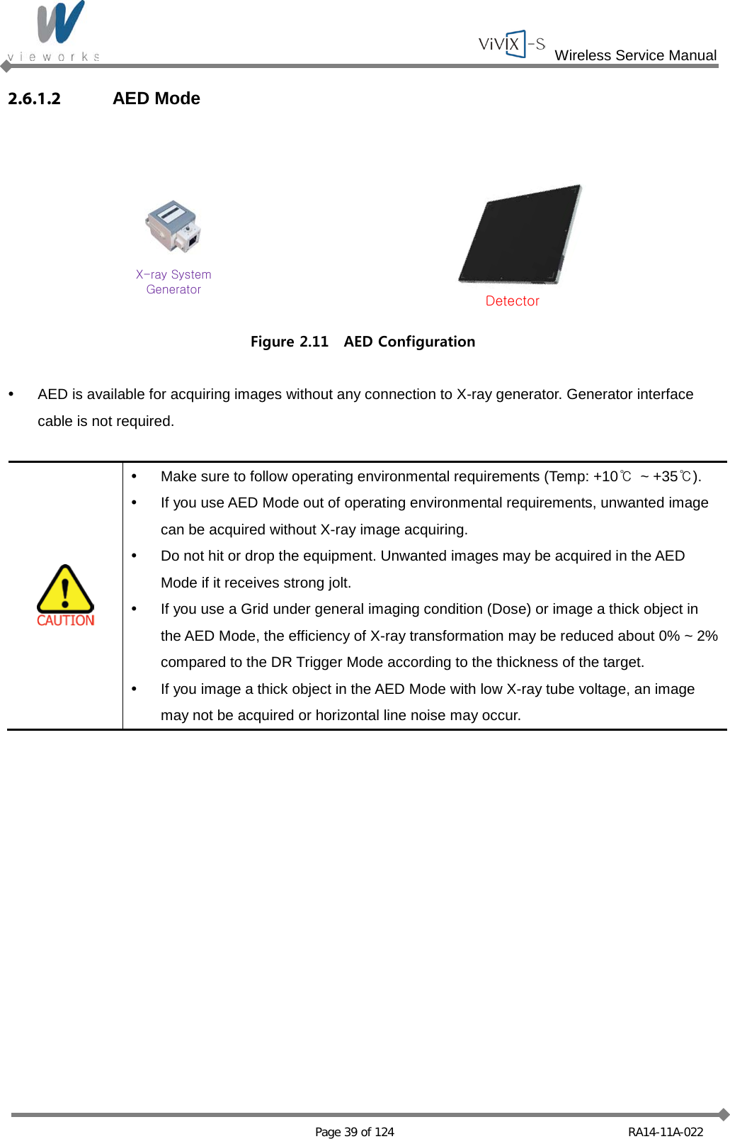
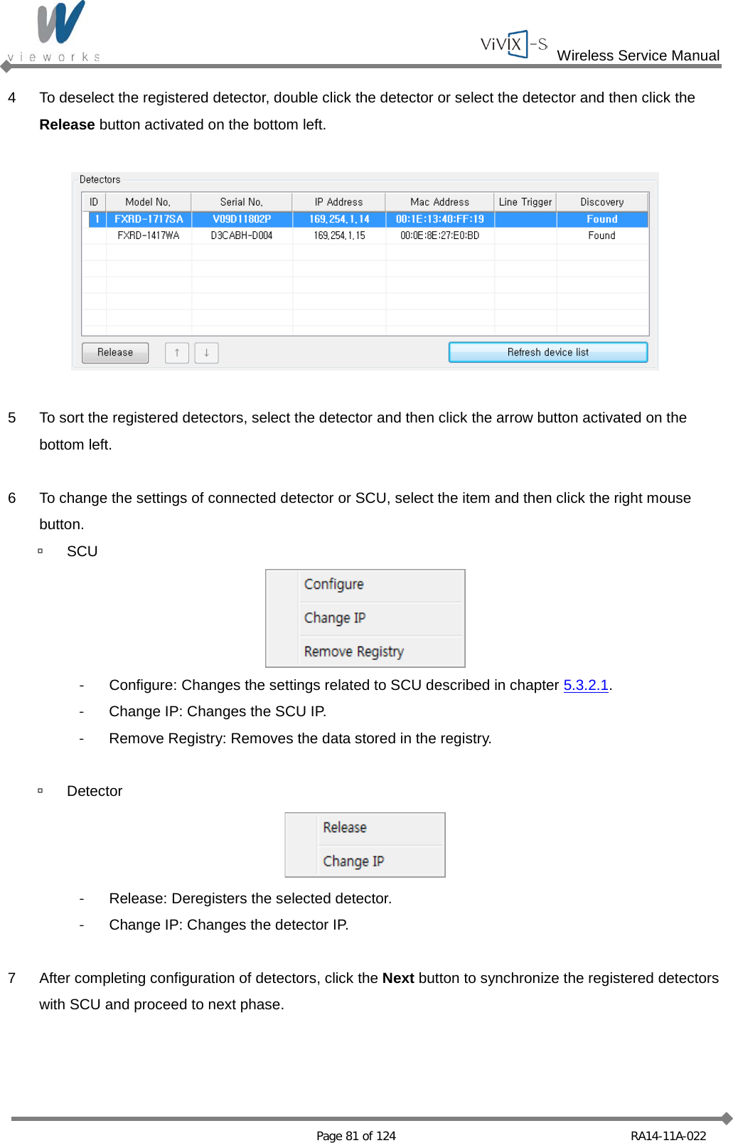
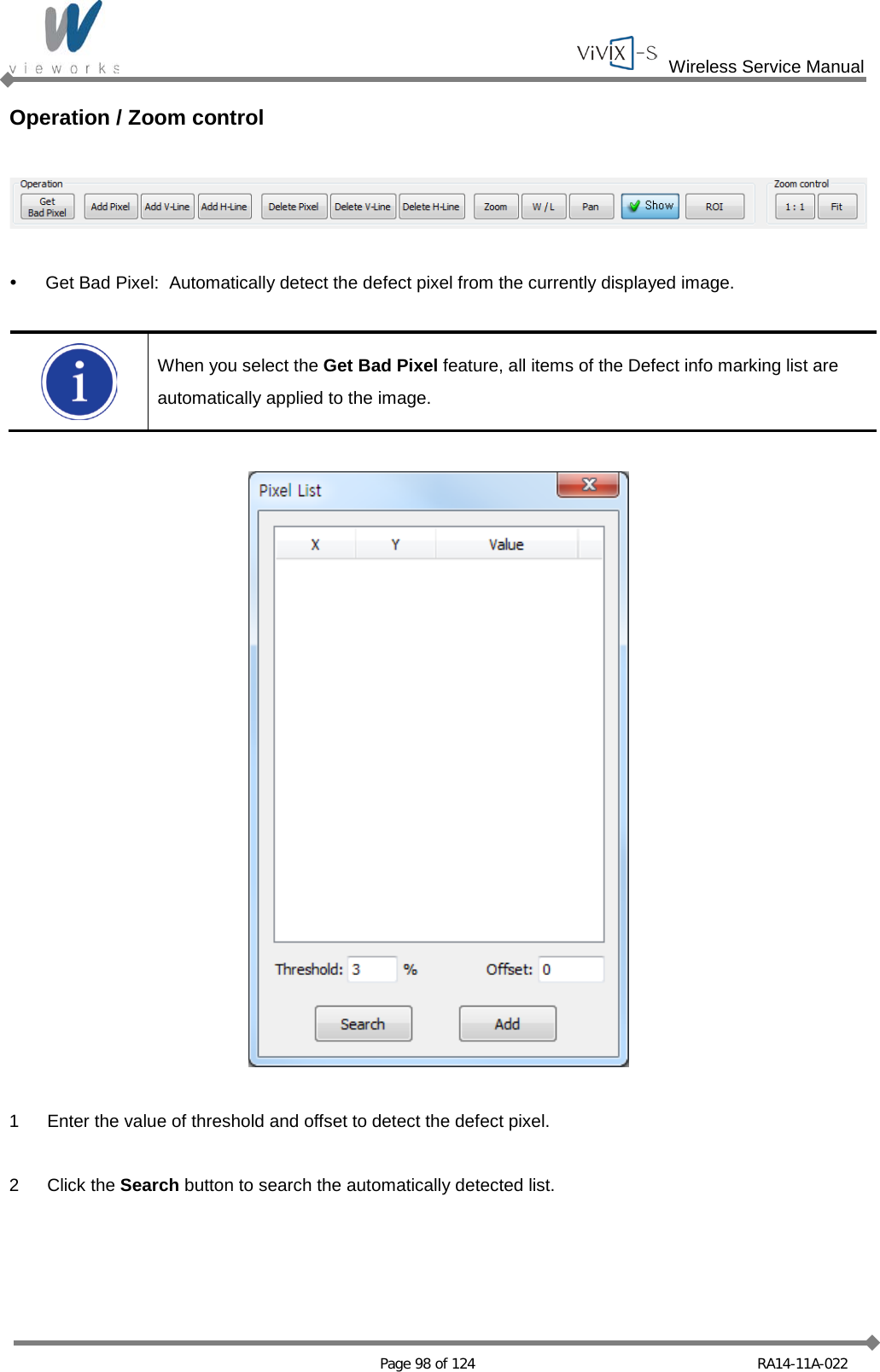
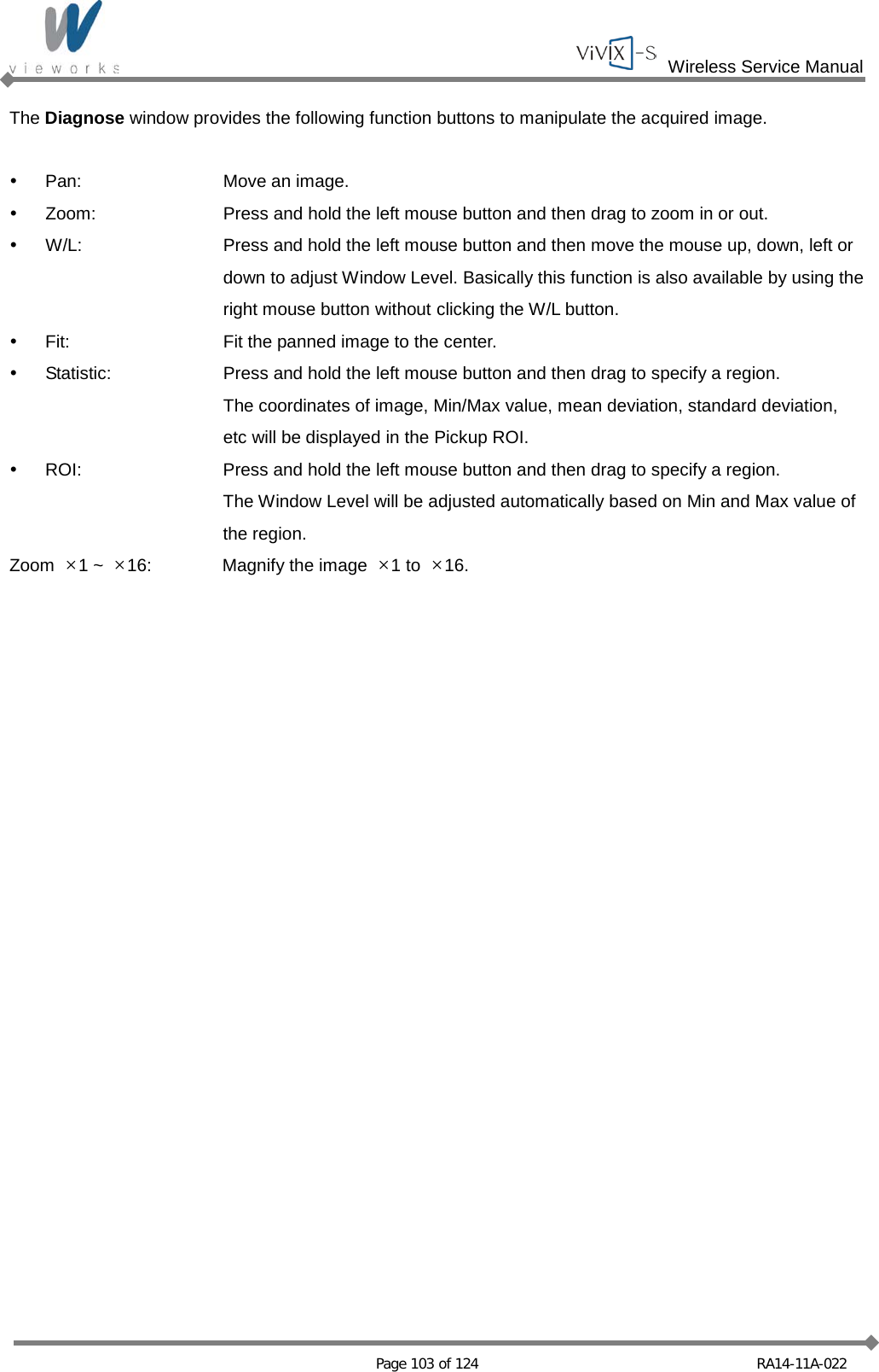
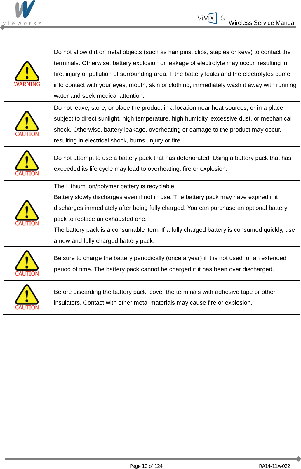
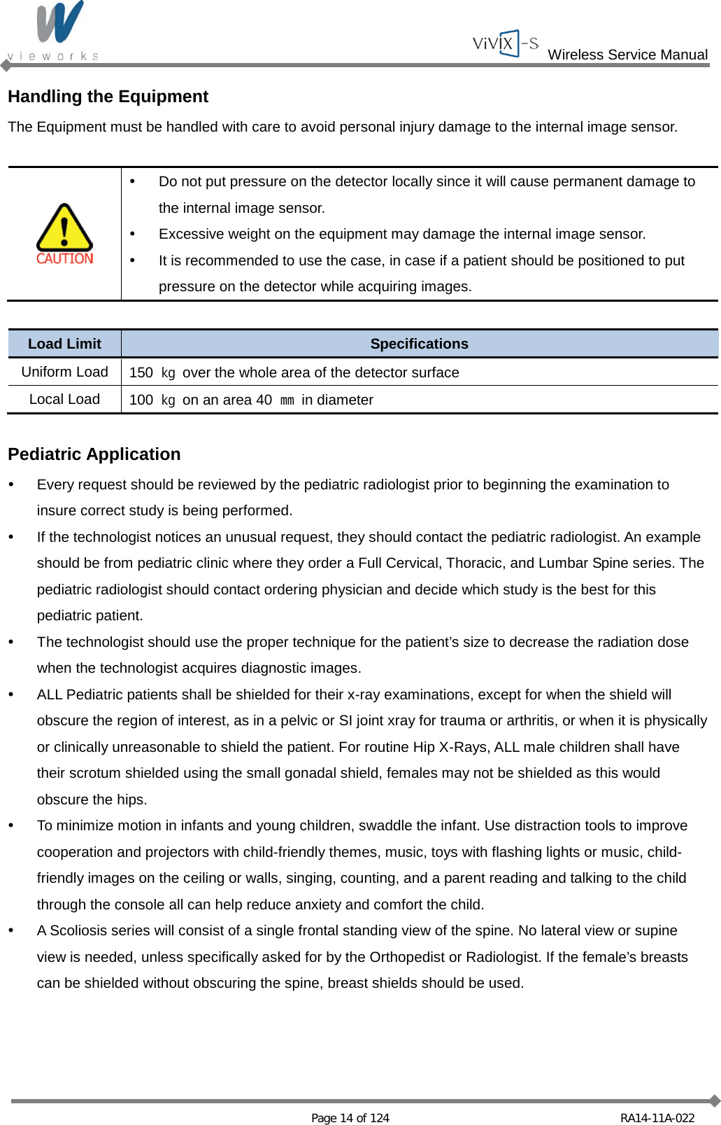
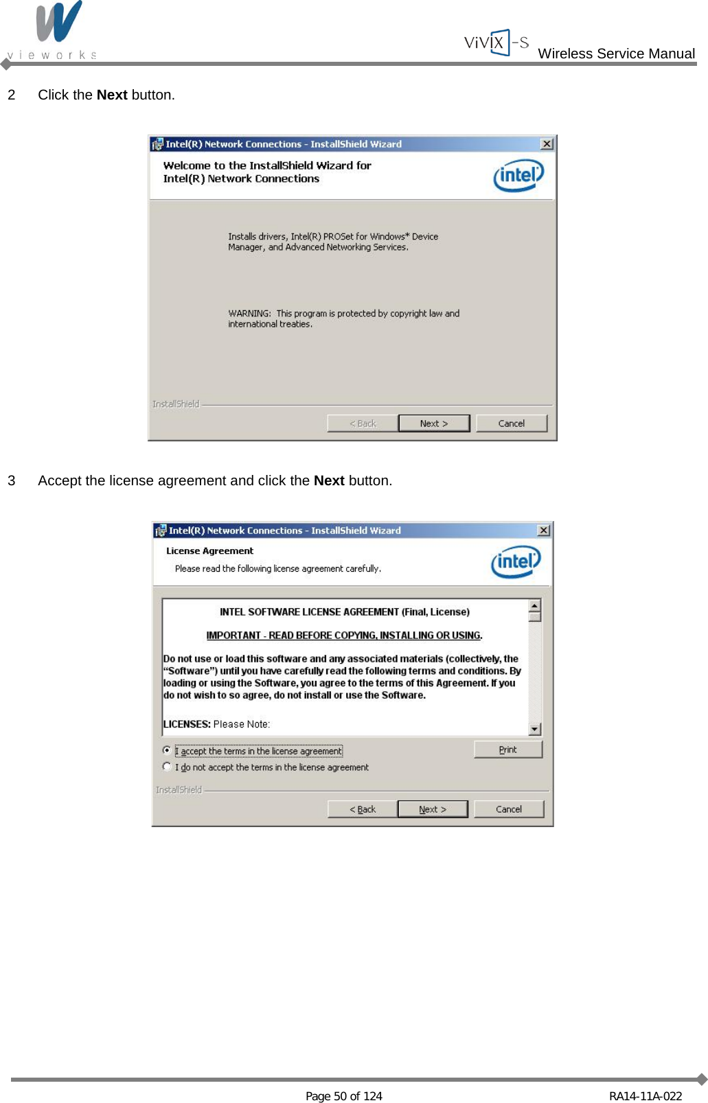
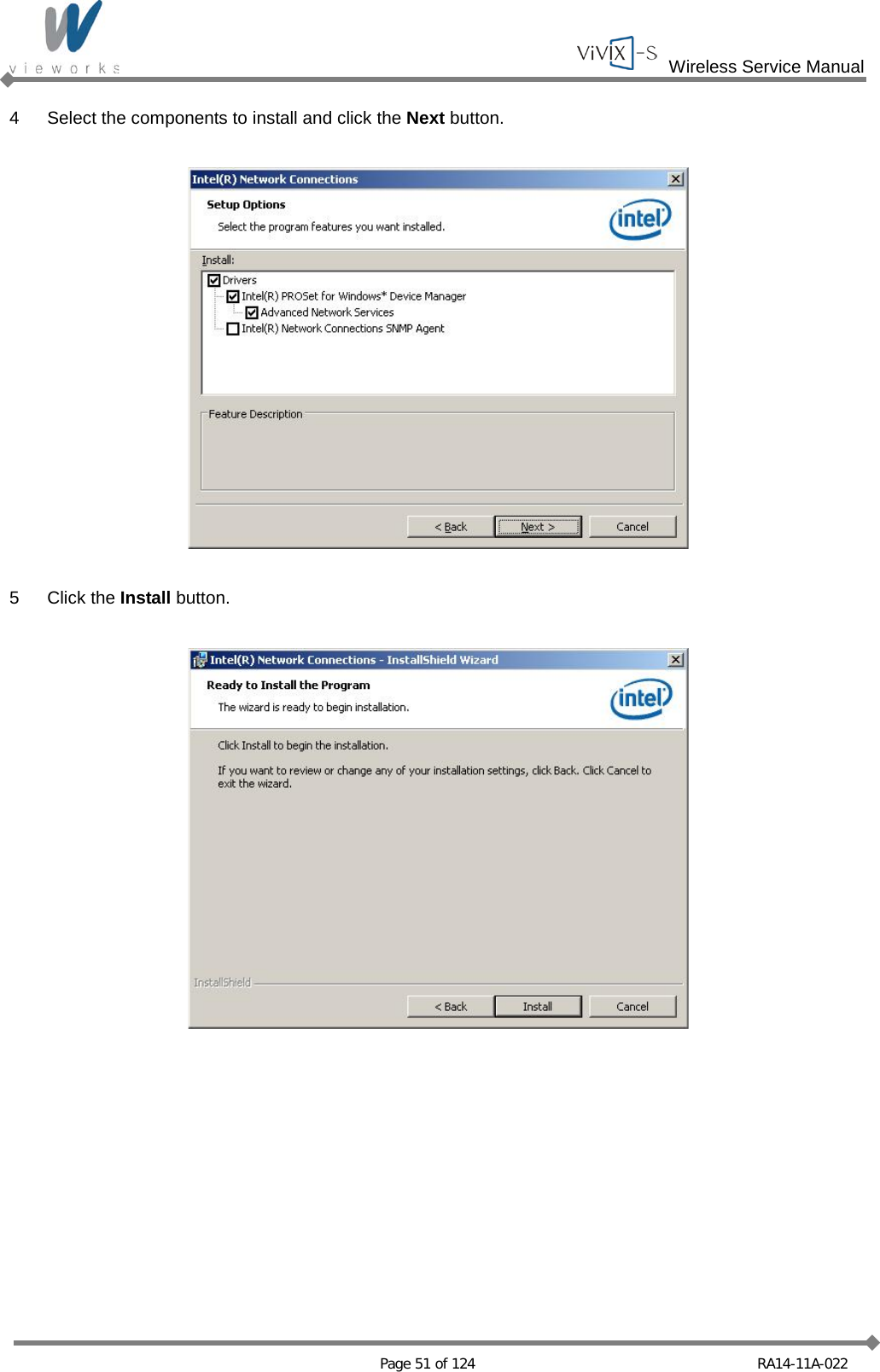
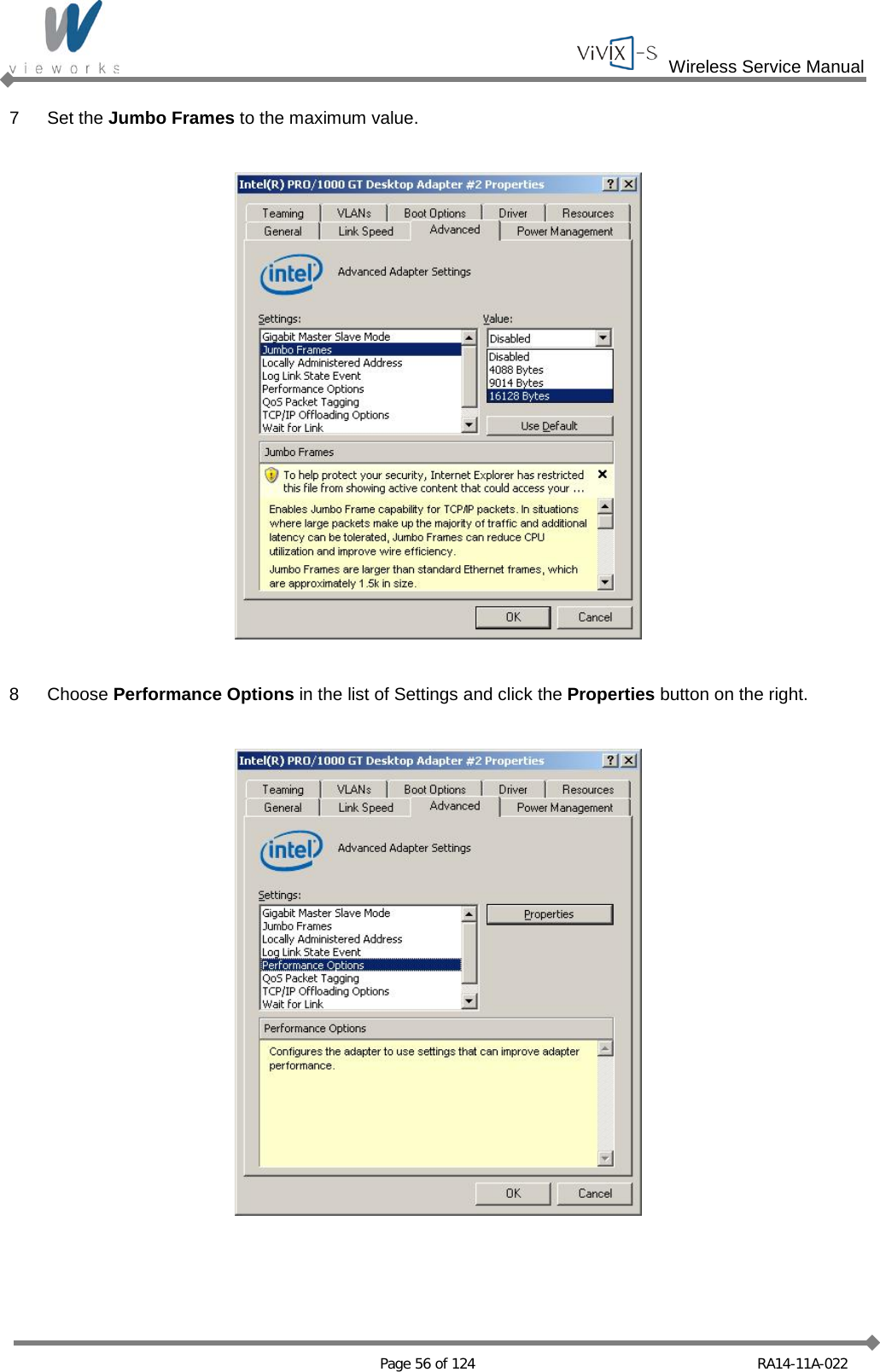
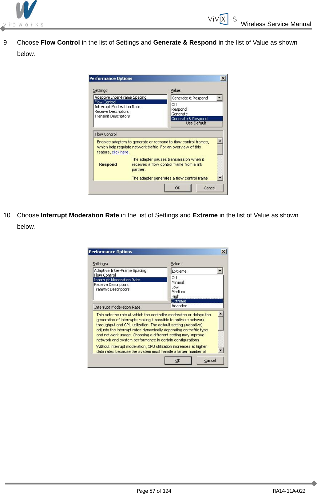
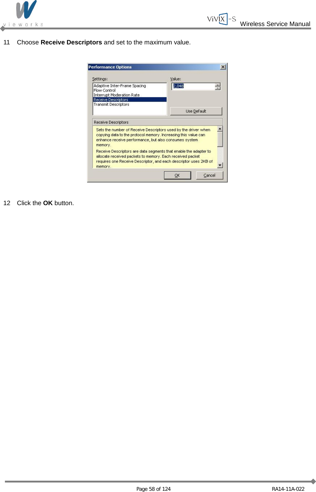
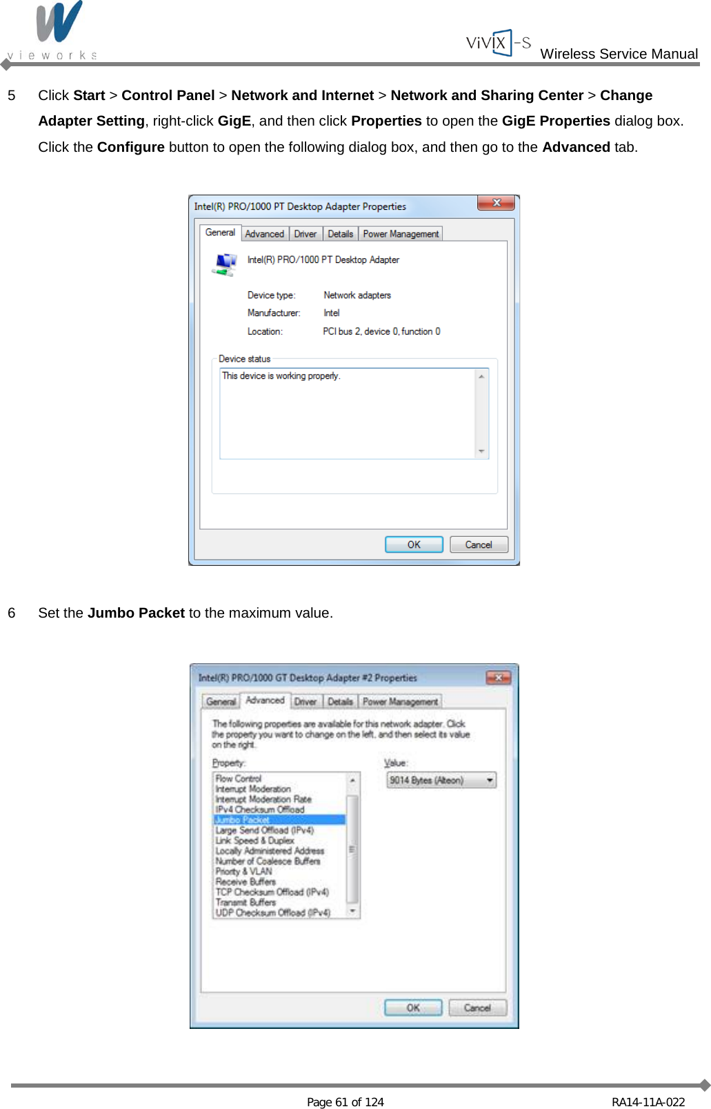
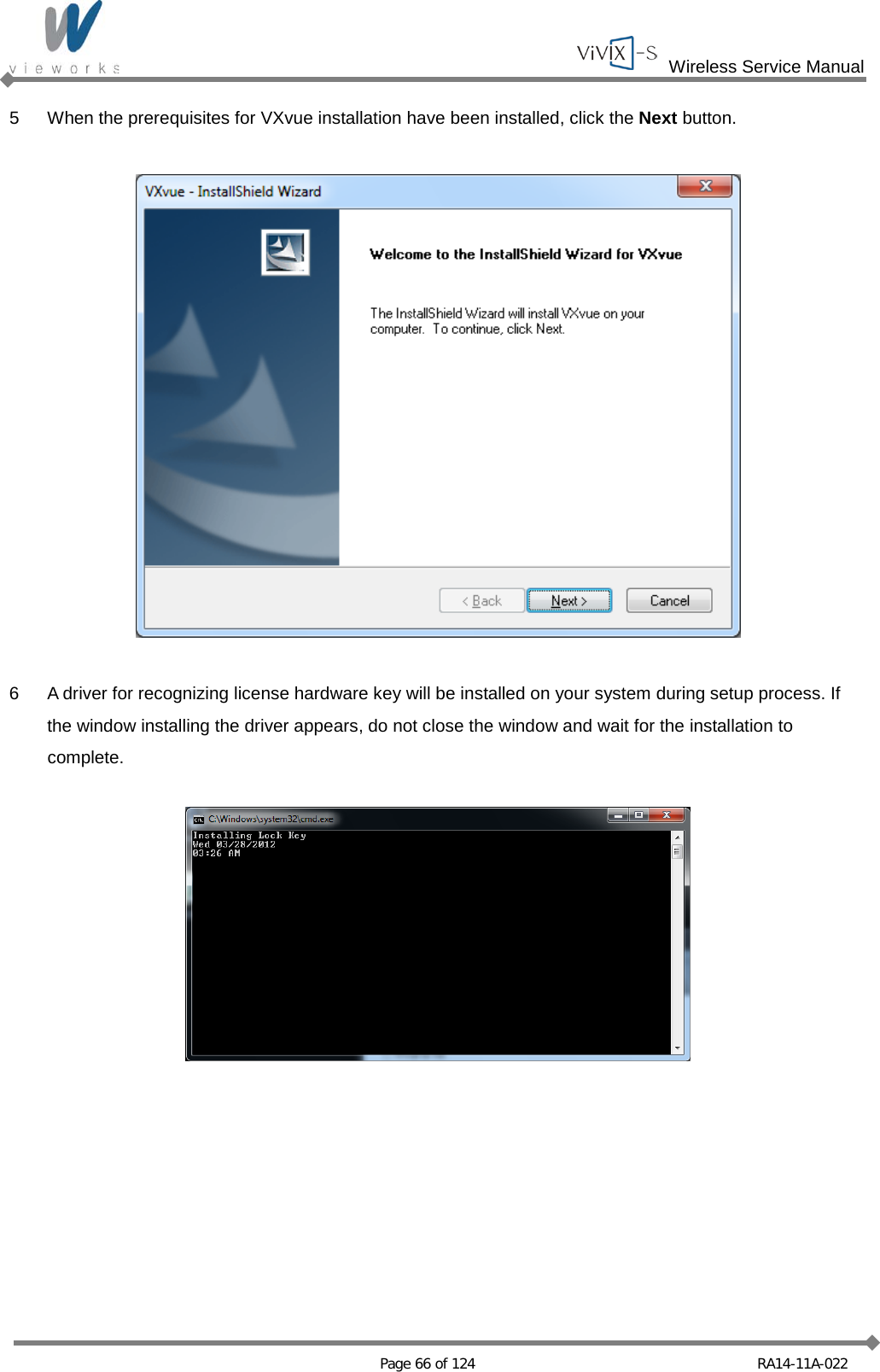
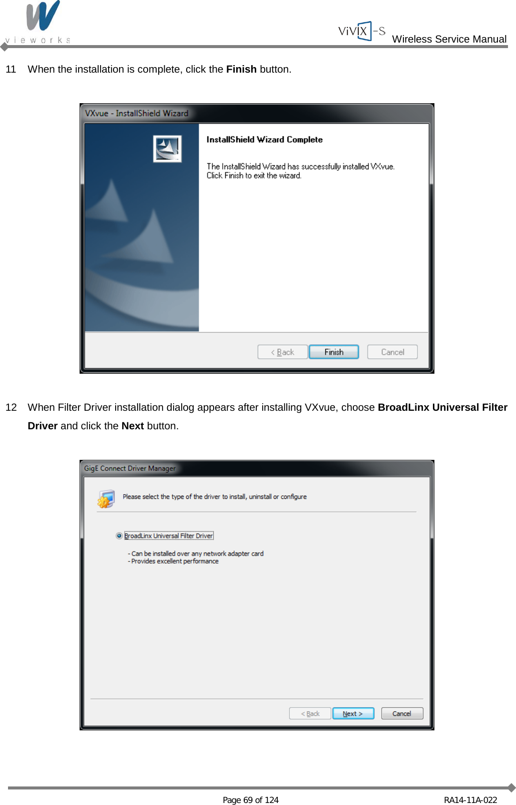
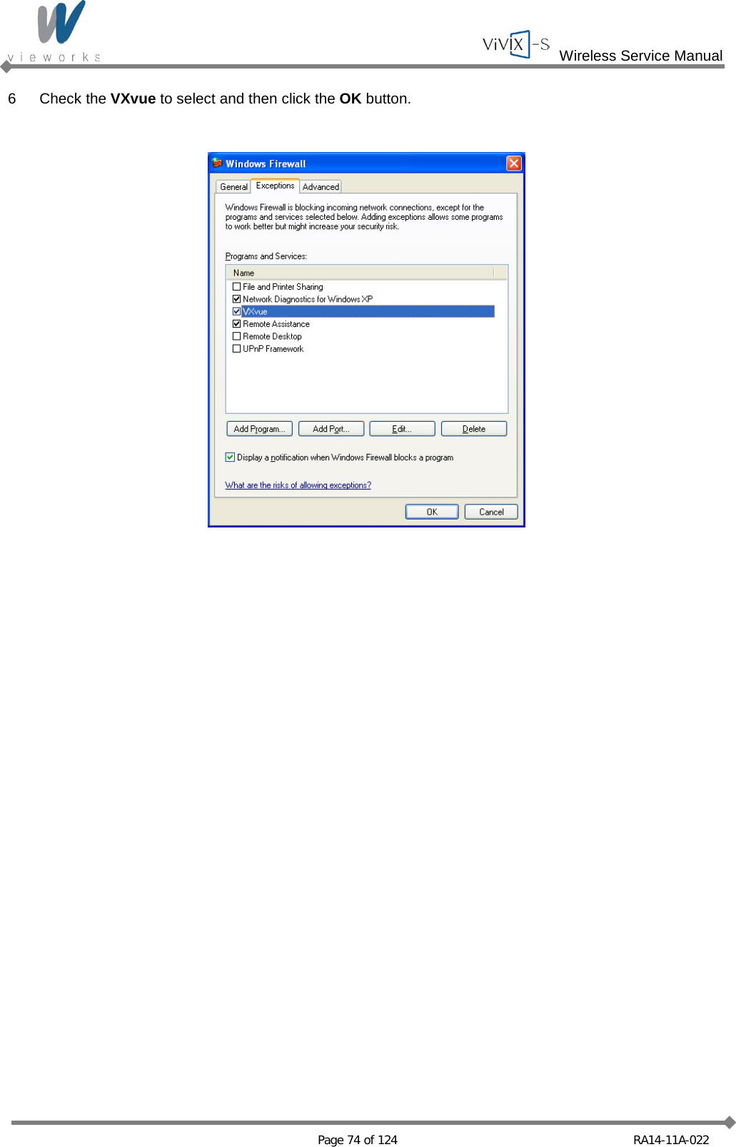
![Wireless Service Manual Page 49 of 124 RA14-11A-022 4.2 Software Installation 4.2.1 Intel Gigabit Controller Driver Installation and Setting Before installing Intel Gigabit Controller Driver, make sure your Ethernet Card is properly installed on the workstation. The recommended Ethernet Card is Intel® Gigabit CT or later. And also, Ethernet Card supporting 1 Gbps or above is available. Gigabit LAN card must support the following requirements. [Jumbo Frames: 9014 Byte], [Receive Descriptors: 2048] This is not a component of ViVIX-S but recommend component. So, you have to use installation package designed for your Gigabit Controller. 1~8 steps may differ according to Gigabit Controller to use. Following procedures are provided as an example to refer to. 1 Click PROXP.exe to start InstallShield Wizard, and then click the Run button.](https://usermanual.wiki/Vieworks/FXRD1417W/User-Guide-2201128-Page-49.png)
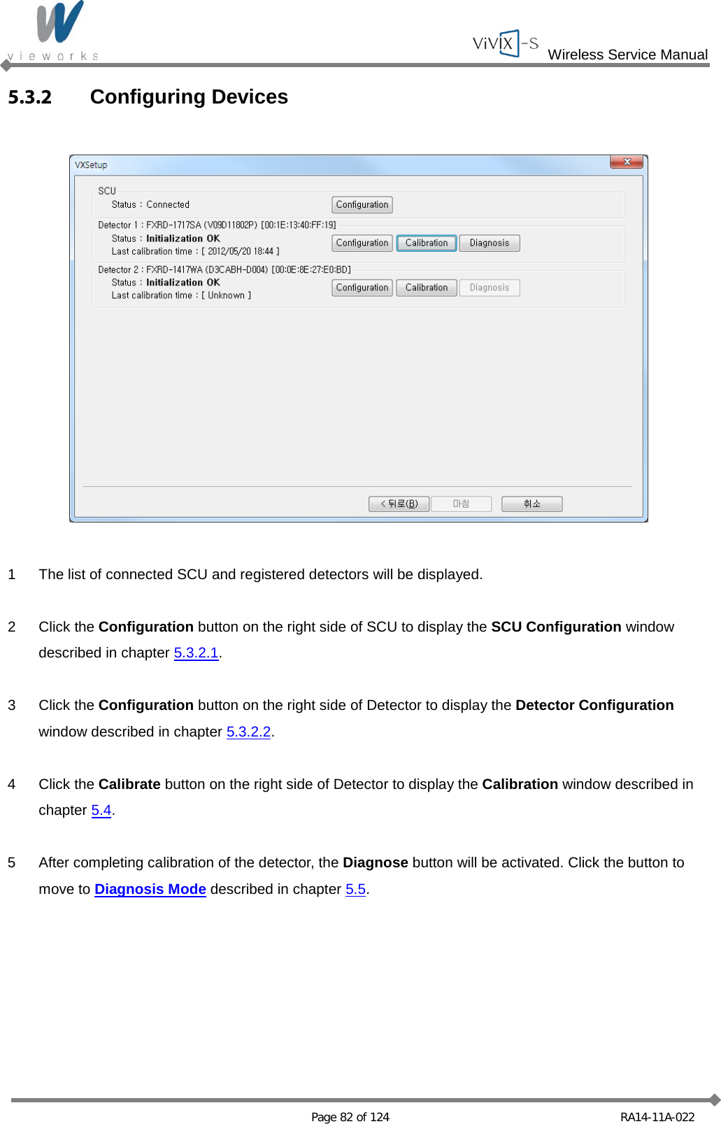
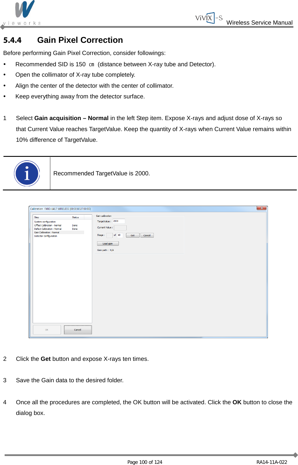
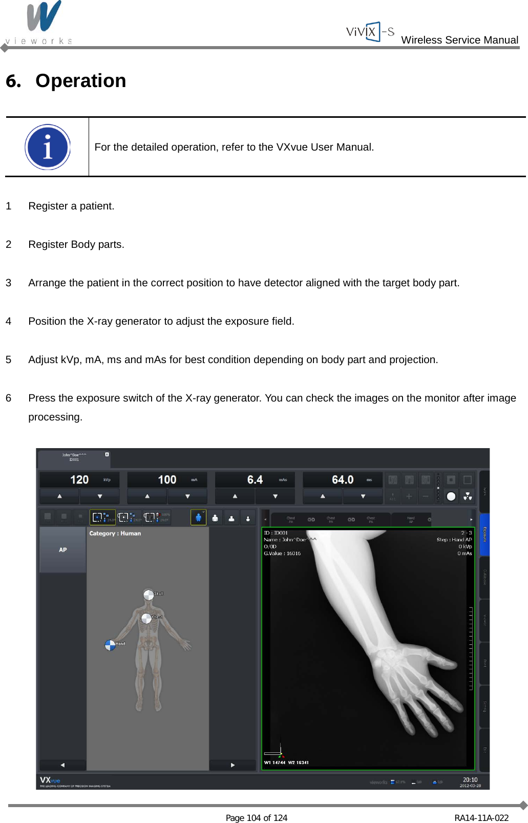
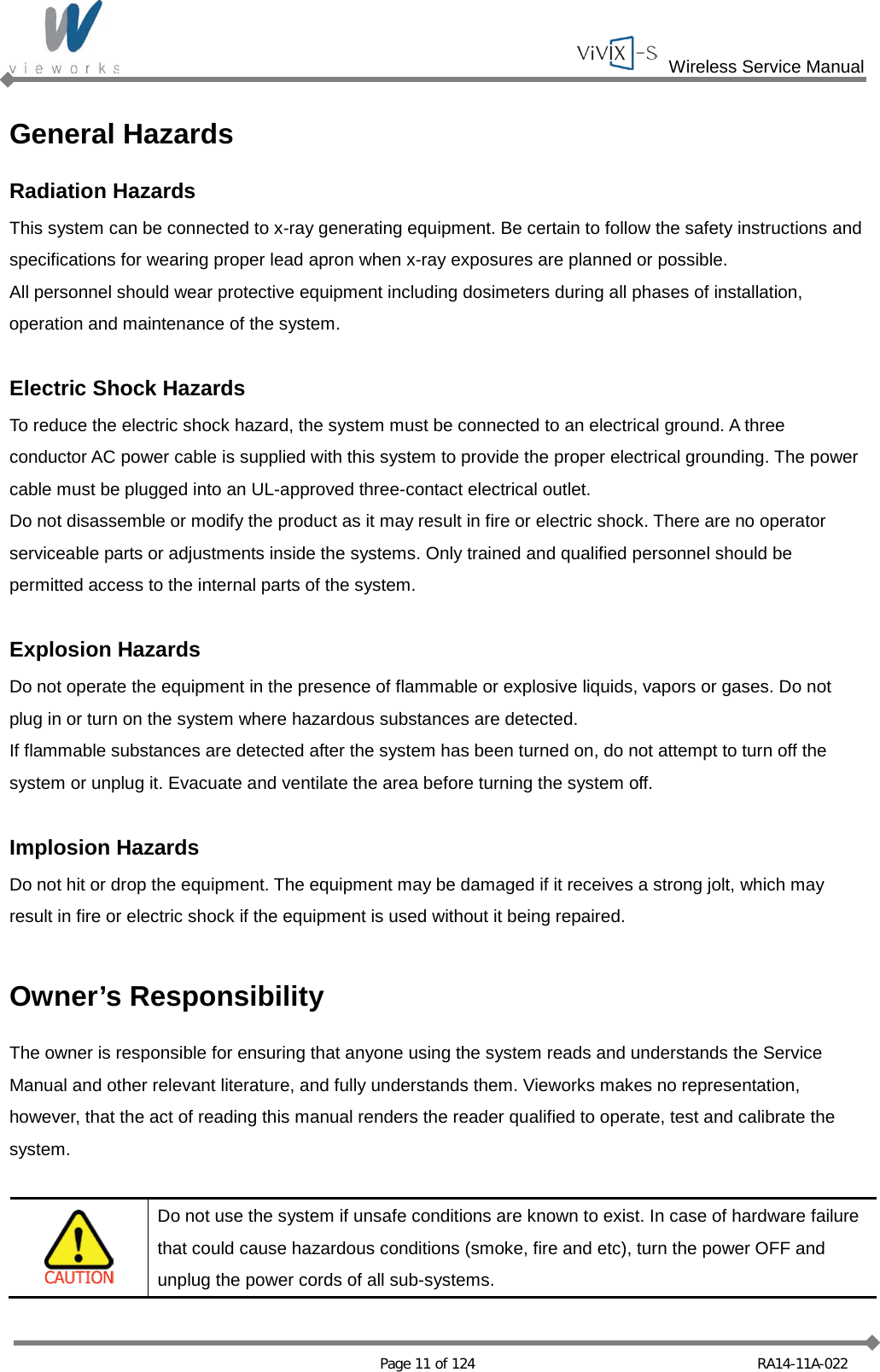
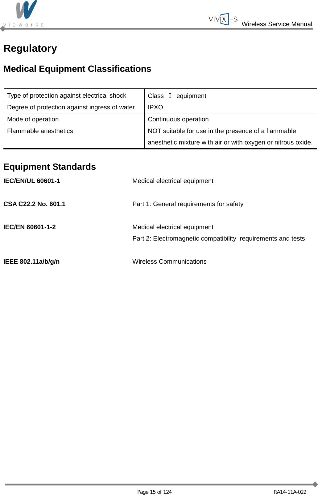
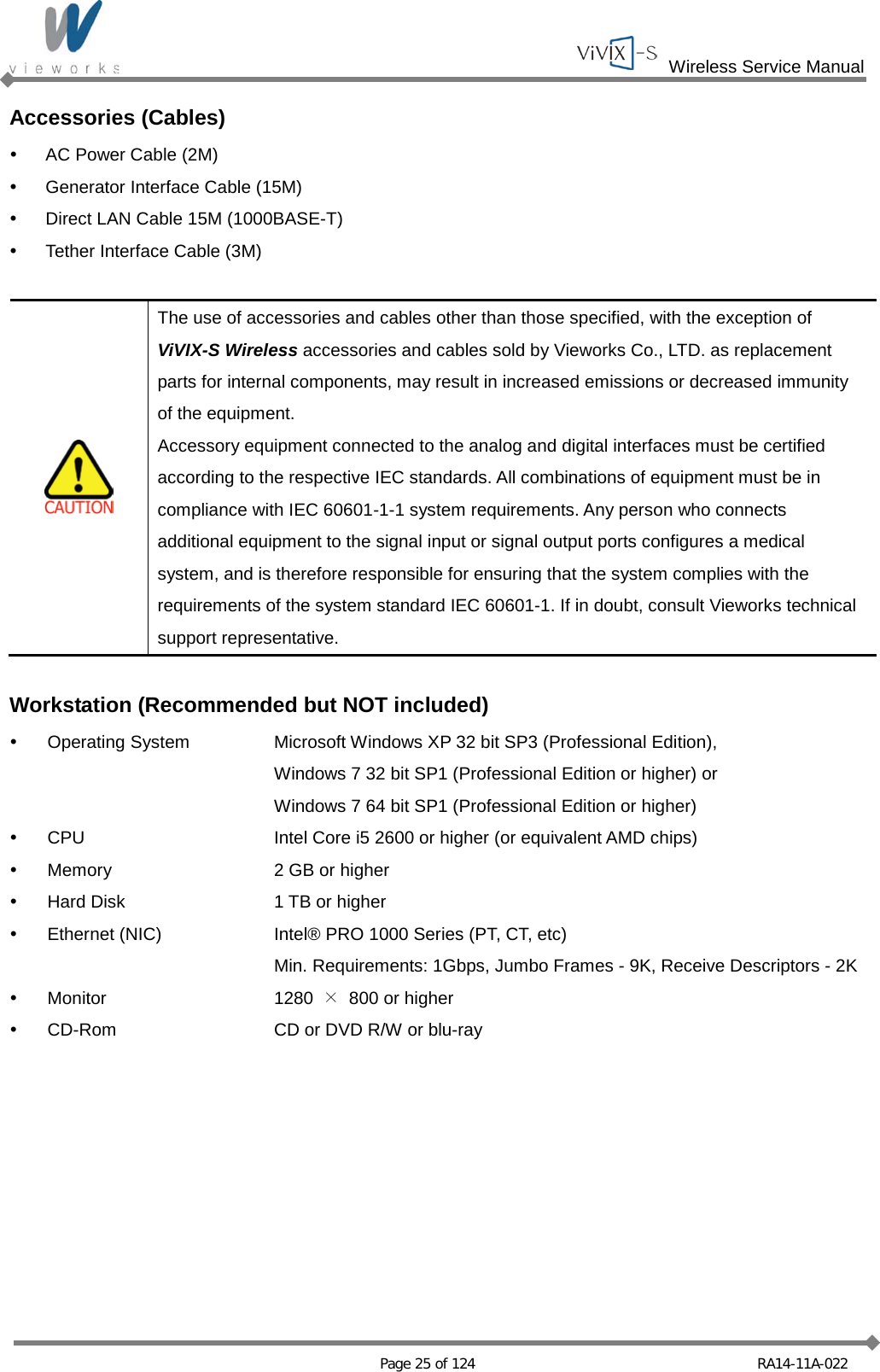
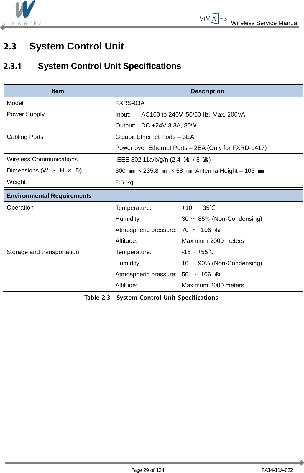
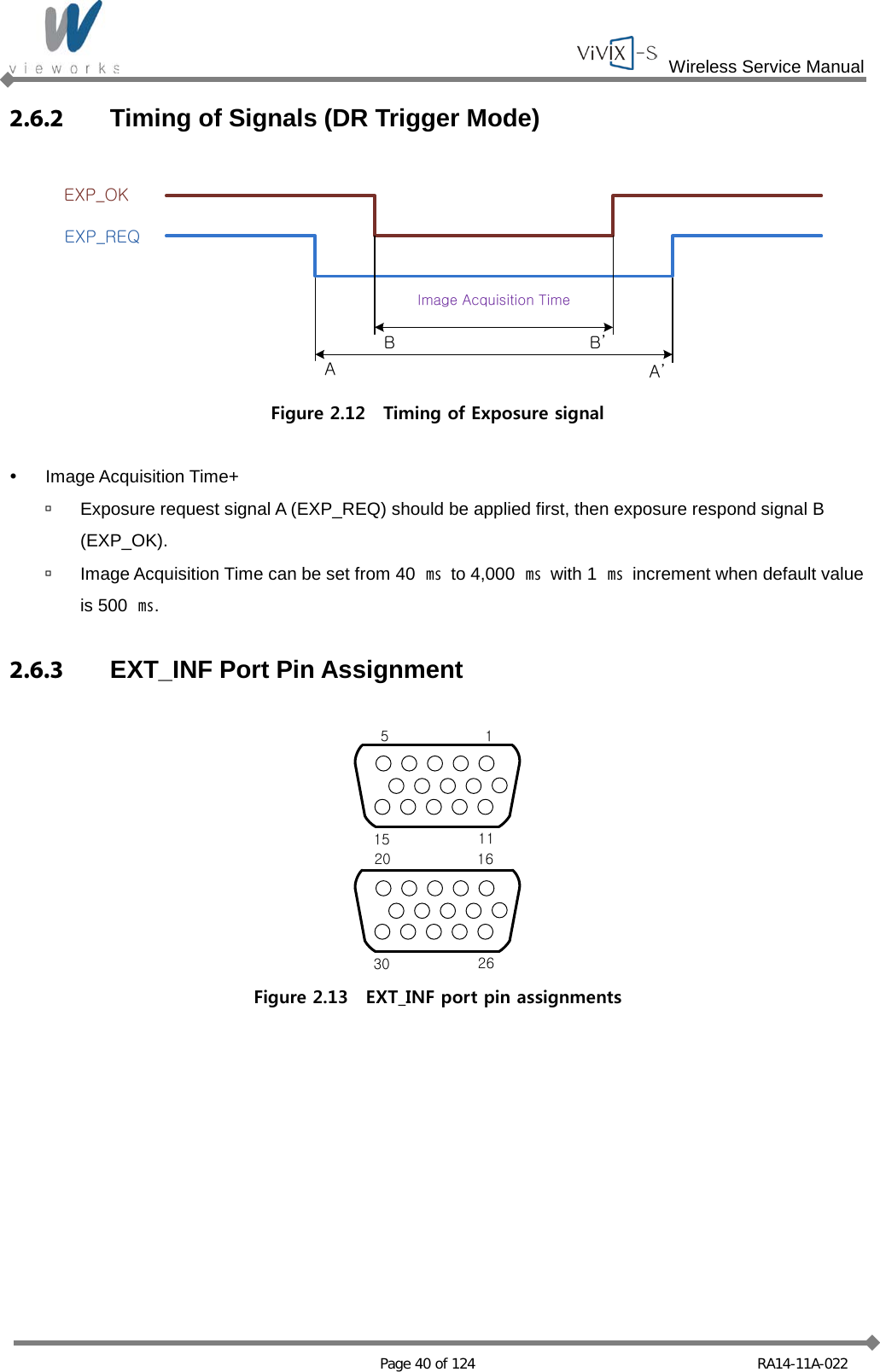
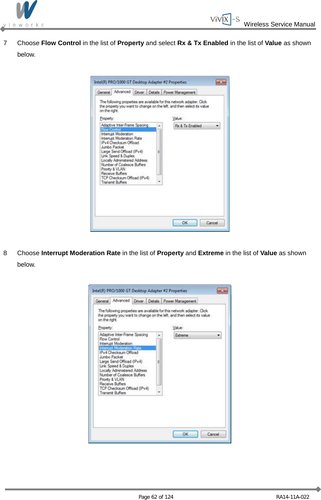
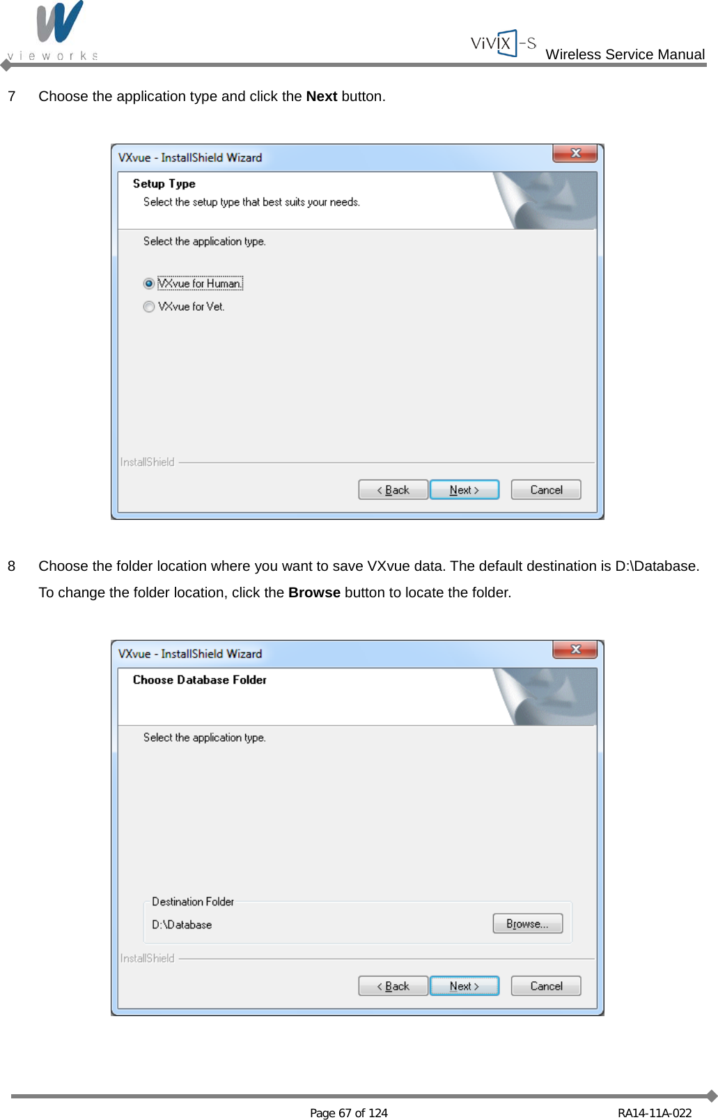
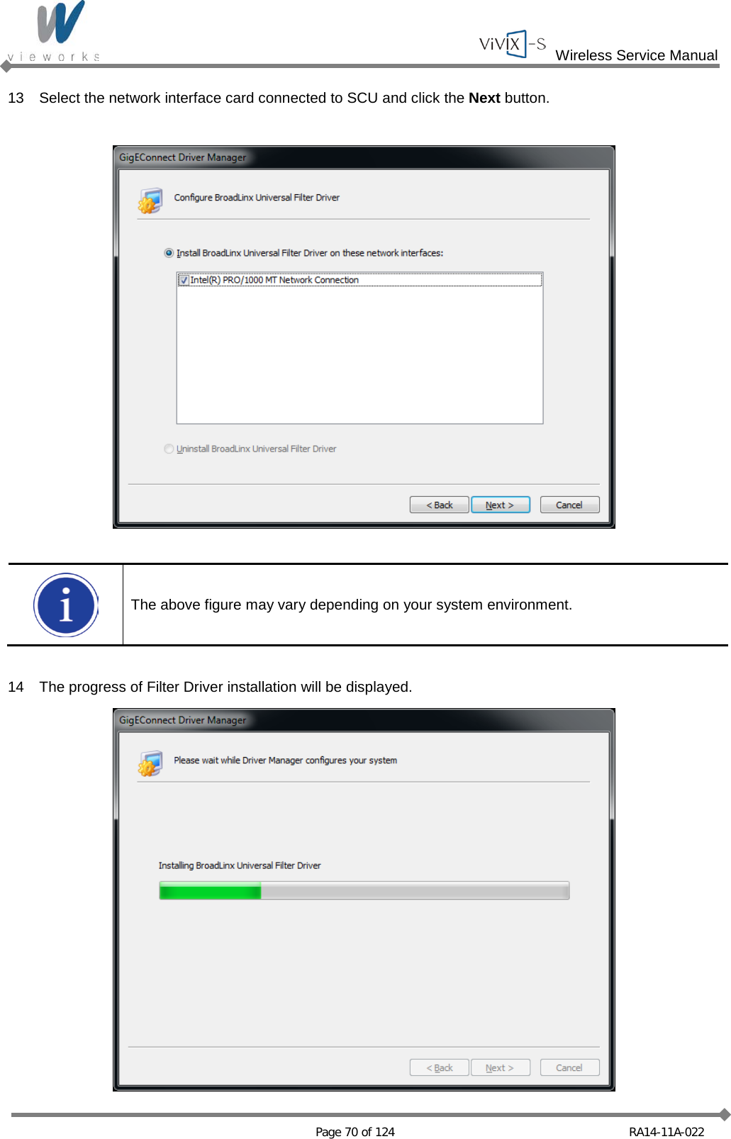
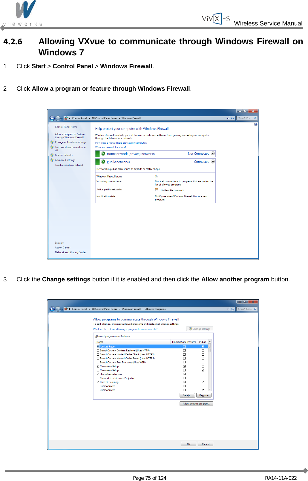
![Wireless Service Manual Page 54 of 124 RA14-11A-022 3 Uncheck all checkboxes except Vieworks Image Filter Driver or GigaLinx Image Filter Driver and Internet Protocol [TCP/IP]. 4 Click the Internet Protocol [TCP/IP] and set the IP as shown below, and then click the Advanced button.](https://usermanual.wiki/Vieworks/FXRD1417W/User-Guide-2201128-Page-54.png)
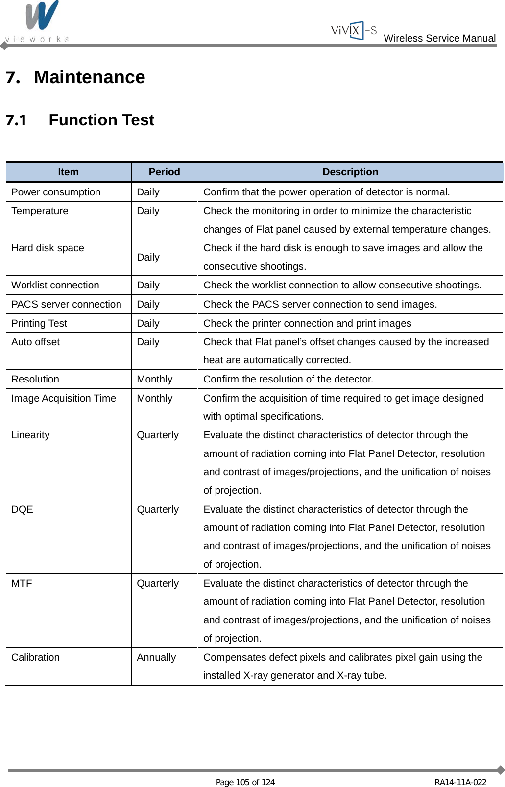
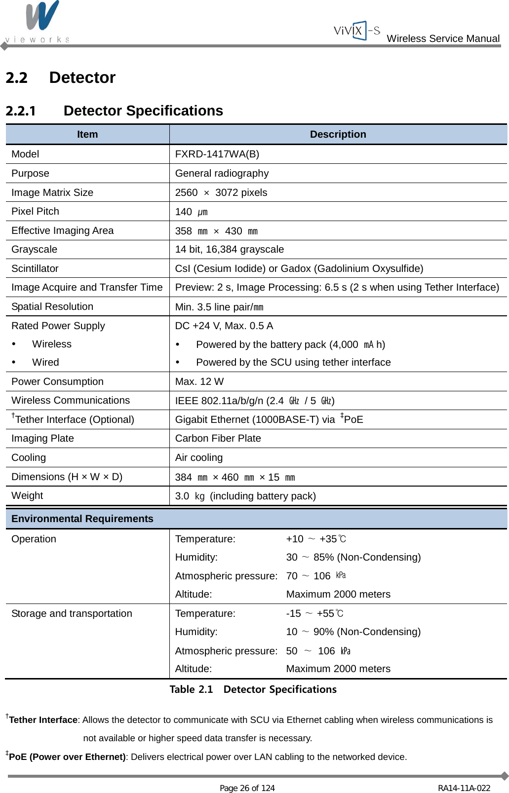
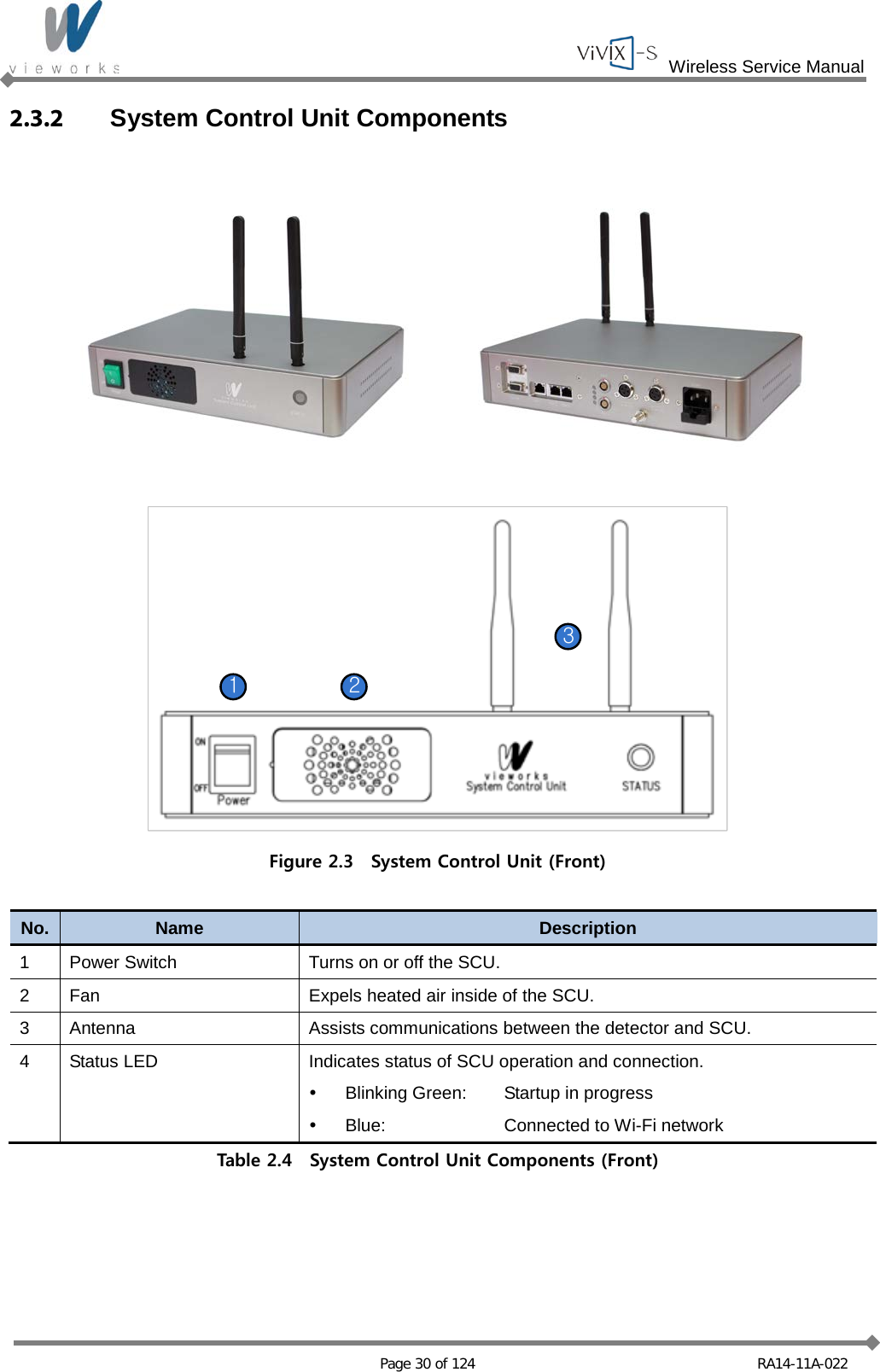
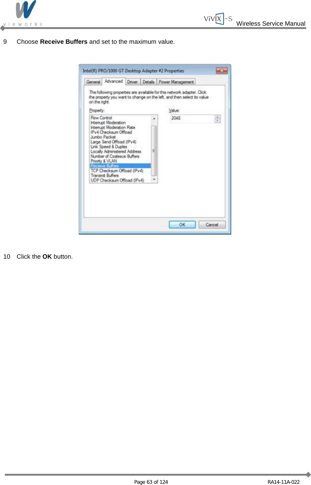
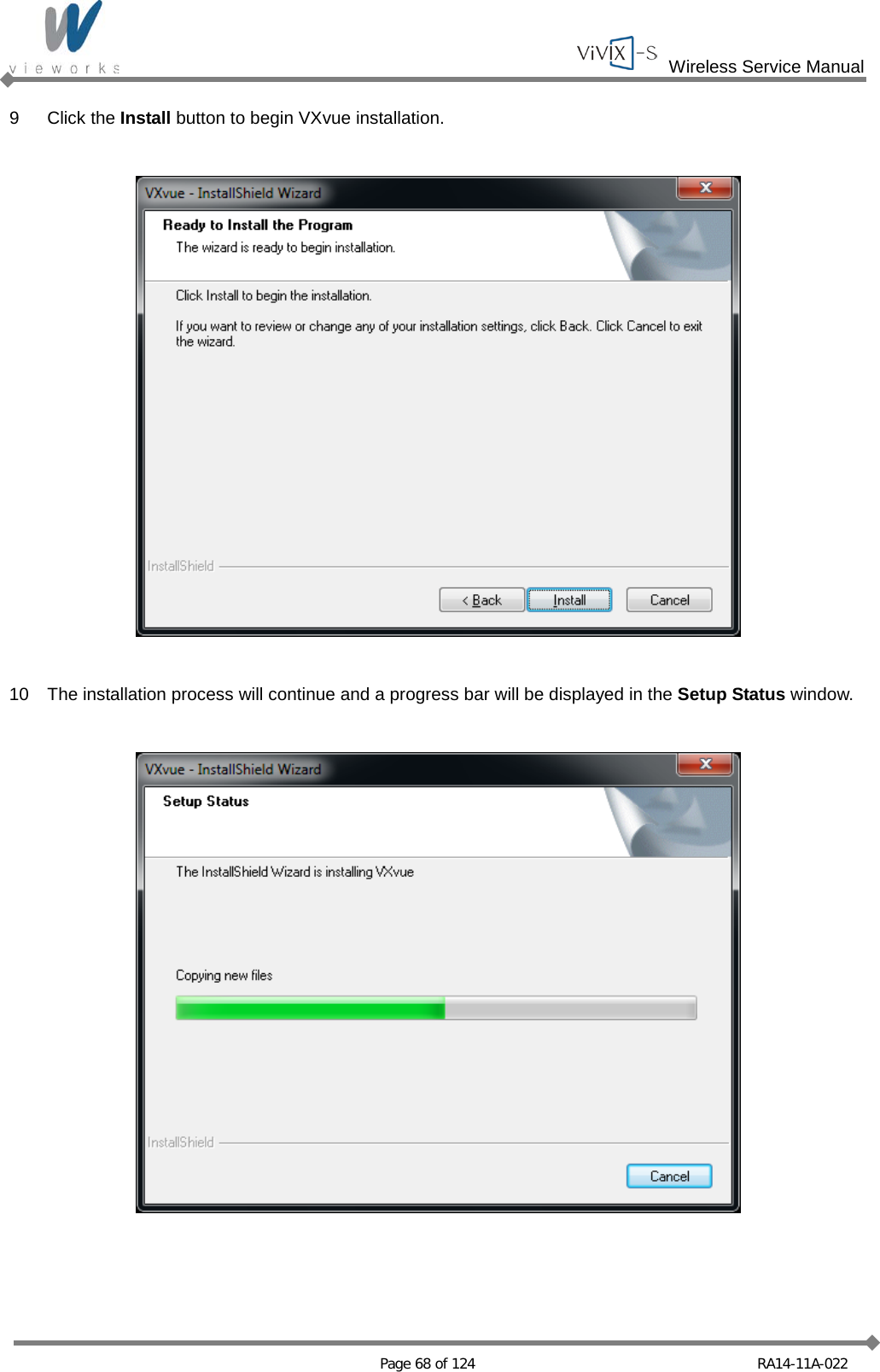
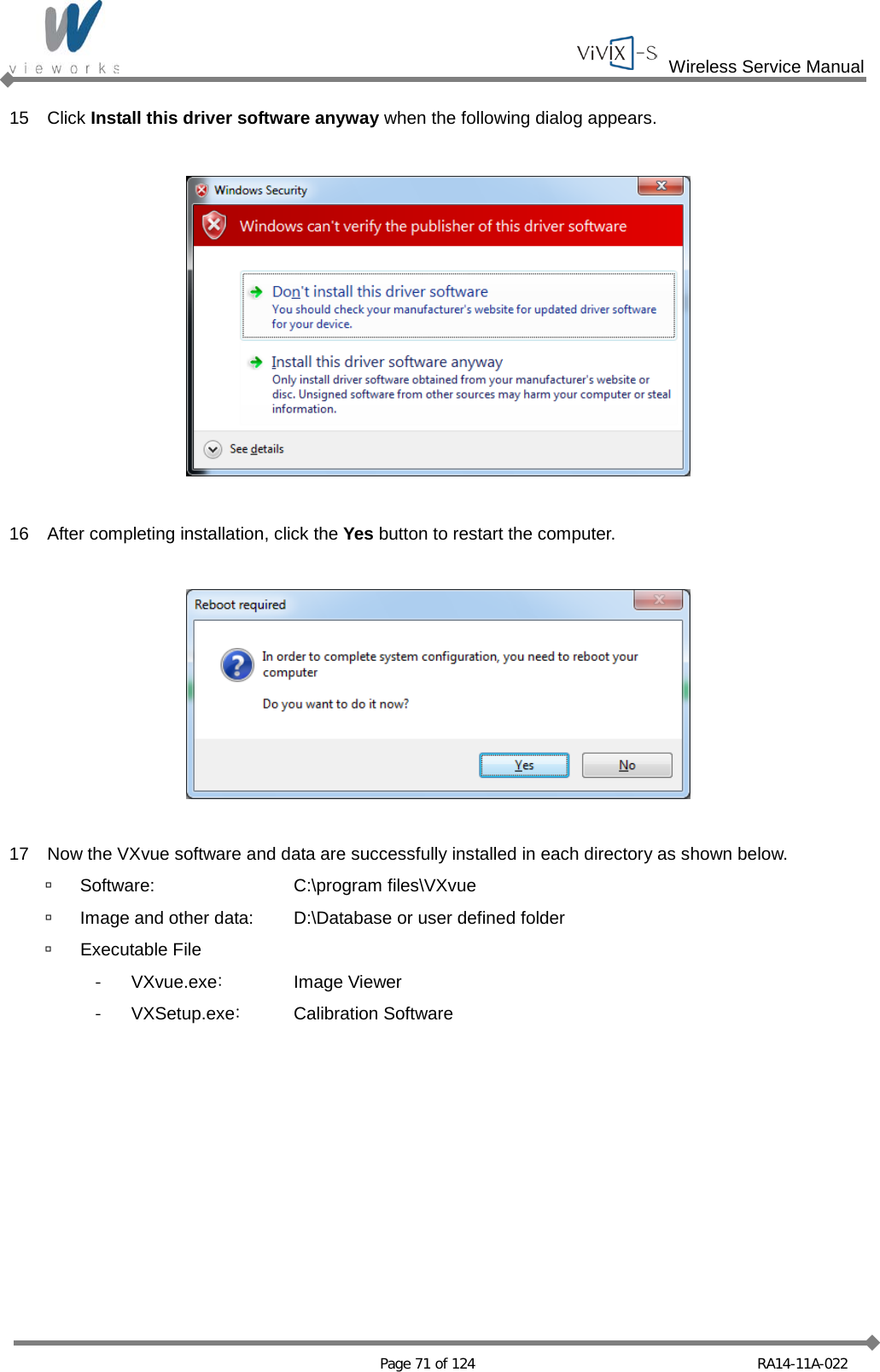
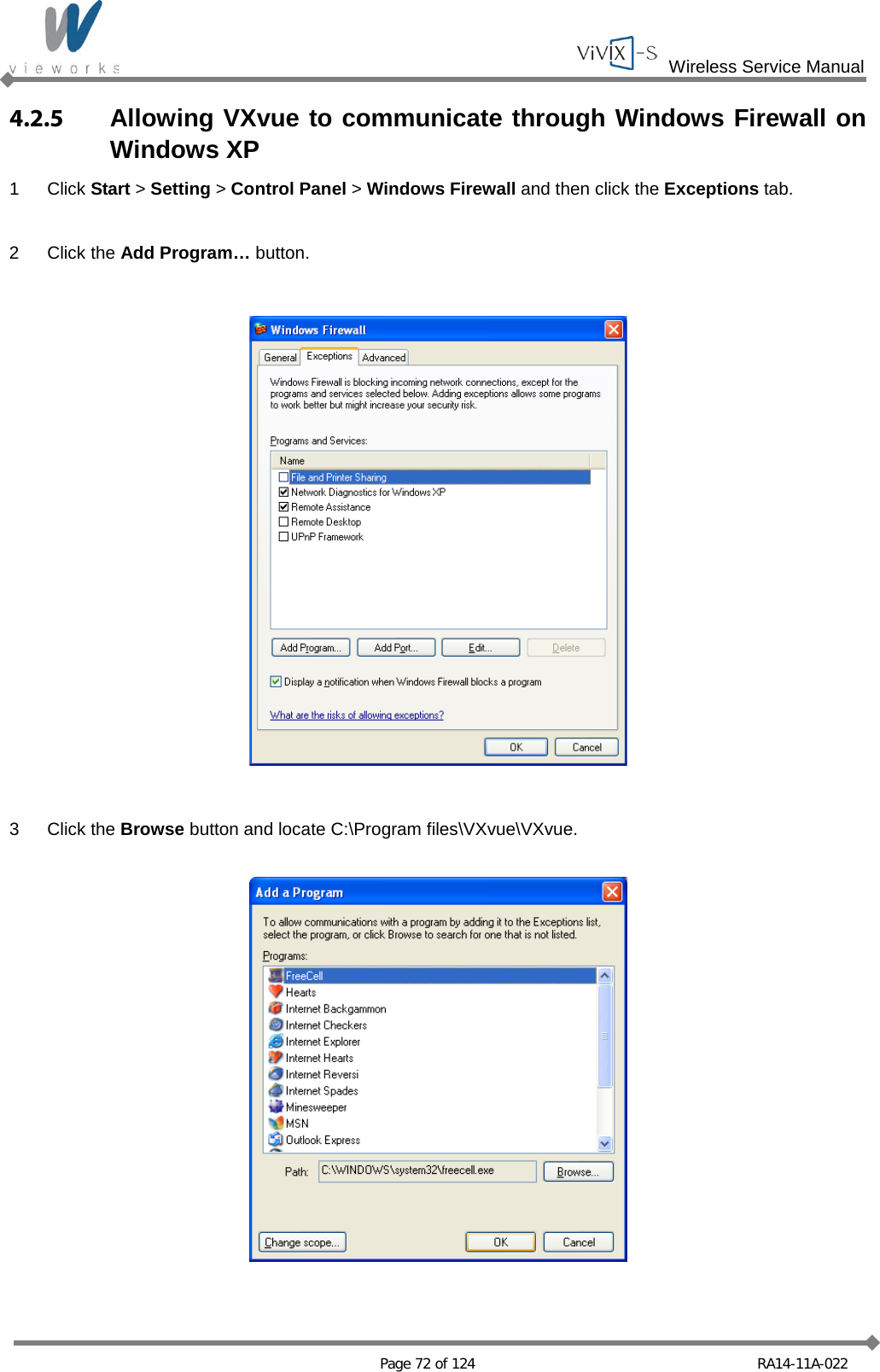
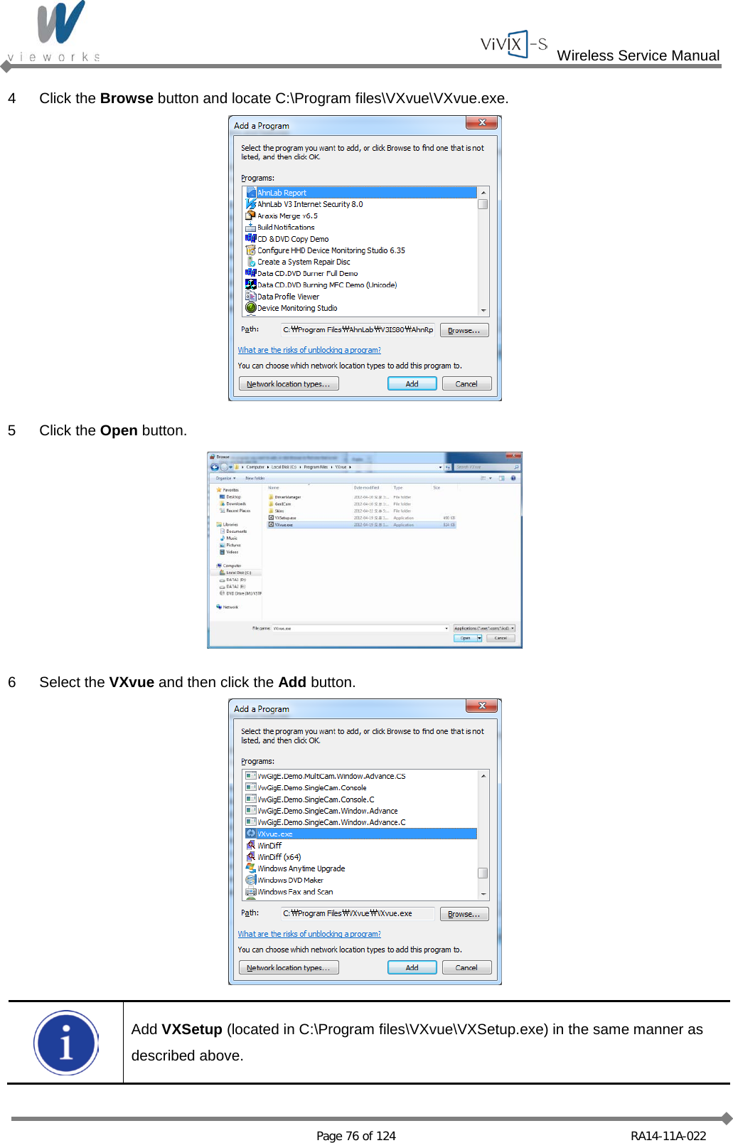
![Wireless Service Manual Page 60 of 124 RA14-11A-022 3 Uncheck all checkboxes except Vieworks Image Filter Driver or GigaLinx Image Filter Driver and Internet Protocol [TCP/IP]. 4 Click the Internet Protocol [TCP/IP] and set the IP as shown below, and then click the Advanced button.](https://usermanual.wiki/Vieworks/FXRD1417W/User-Guide-2201128-Page-60.png)

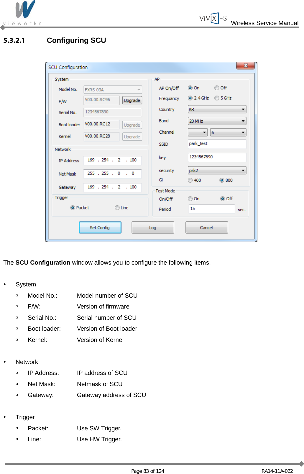
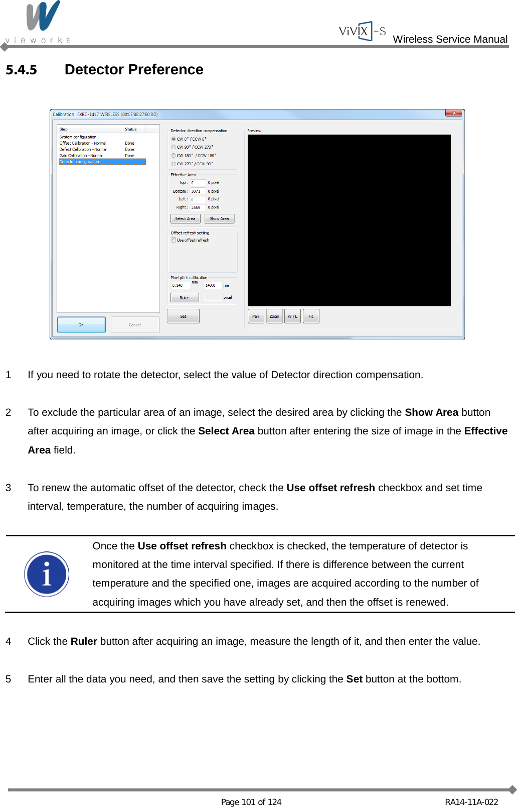
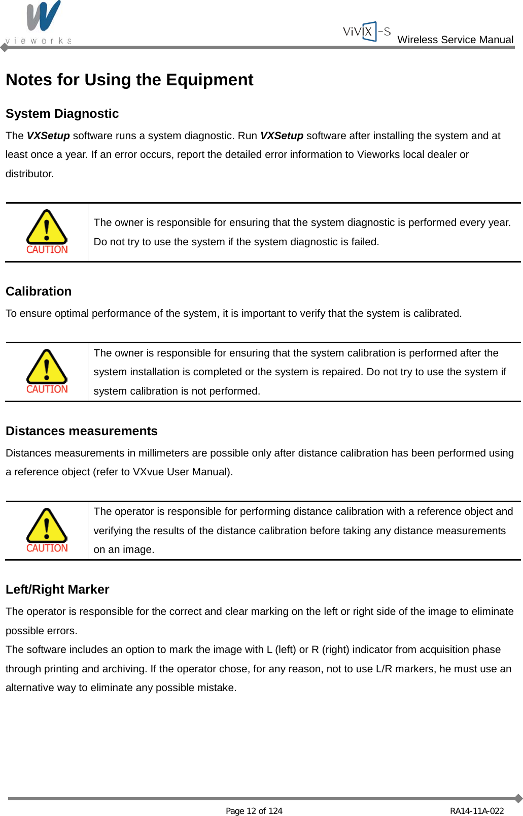
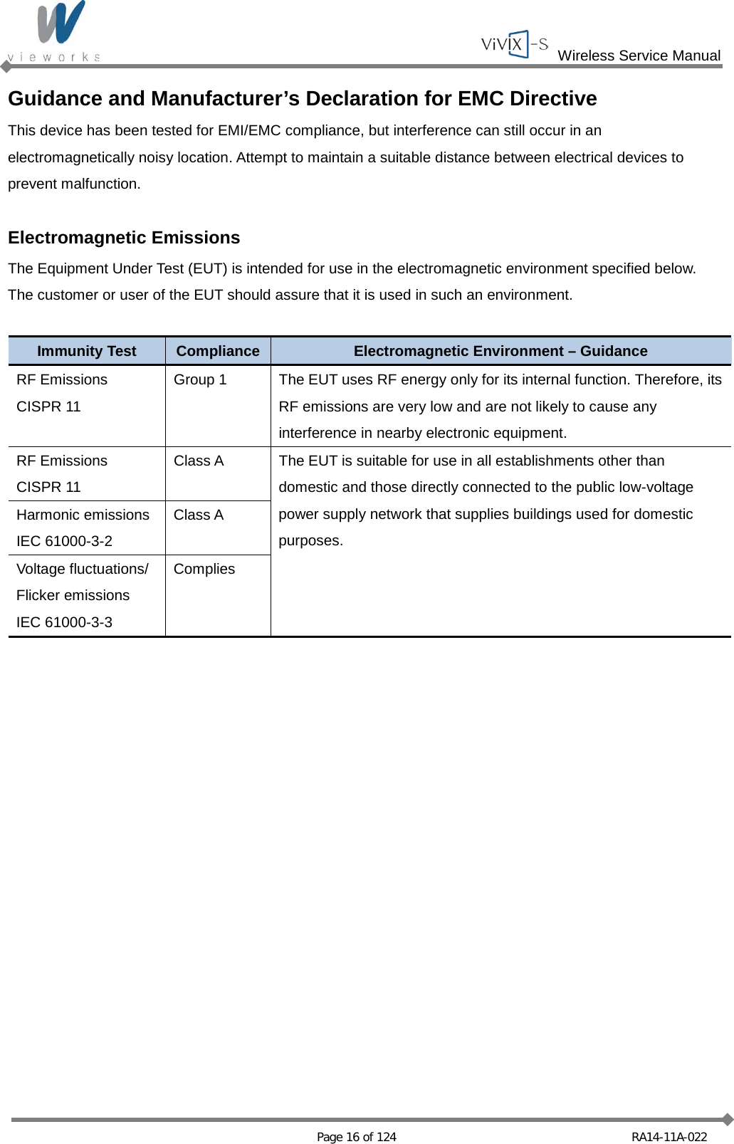
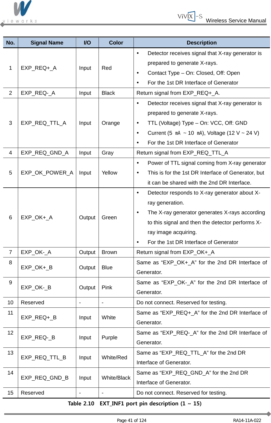
![Wireless Service Manual Page 79 of 124 RA14-11A-022 Generator Communication Settings Remarks CPI Serial Port COM 1 19200 bps / data 8 / stop 2 / none / none EMD Serial Port COM 3 19200 bps / data 8 / stop 1 / none / none Set WorkStation 2, 3 SEDECAL Shared memory Window title: ‘window title’ For Human in DRApp.ini [SETTINGS] DRAppName = window title For Vet in AppName.ini [CONFIG] APPNAME= window title 5.3 Detector Configuration In this phase, defect pixels are corrected and gained pixels are calibrated using installed x-ray generator and x-ray tube. The detector needs to warm up at least 30 minutes before performing the calibration. The calibration should be performed on the following cases. Detector installation X-ray generator replacement X-ray tube replacement Exposure section Value change Gain Type change](https://usermanual.wiki/Vieworks/FXRD1417W/User-Guide-2201128-Page-79.png)