Weir Group Management Services STXMPM monitor the operation of components of a drilling rig User Manual Name
Weir Group Management Services Limited monitor the operation of components of a drilling rig Name
Contents
- 1. Setup guide
- 2. setup guide
Setup guide


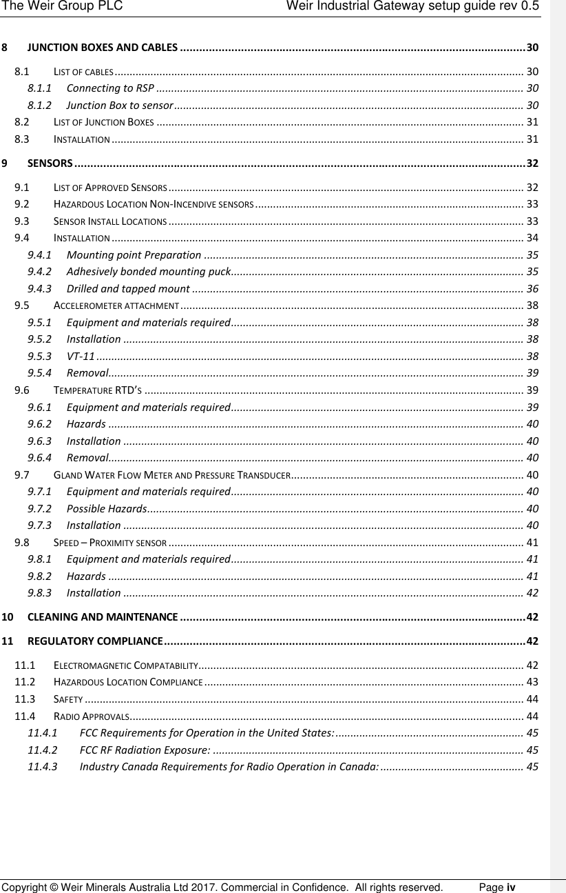
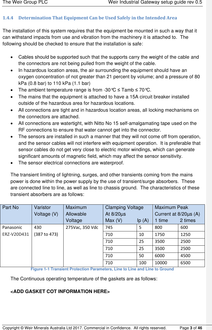
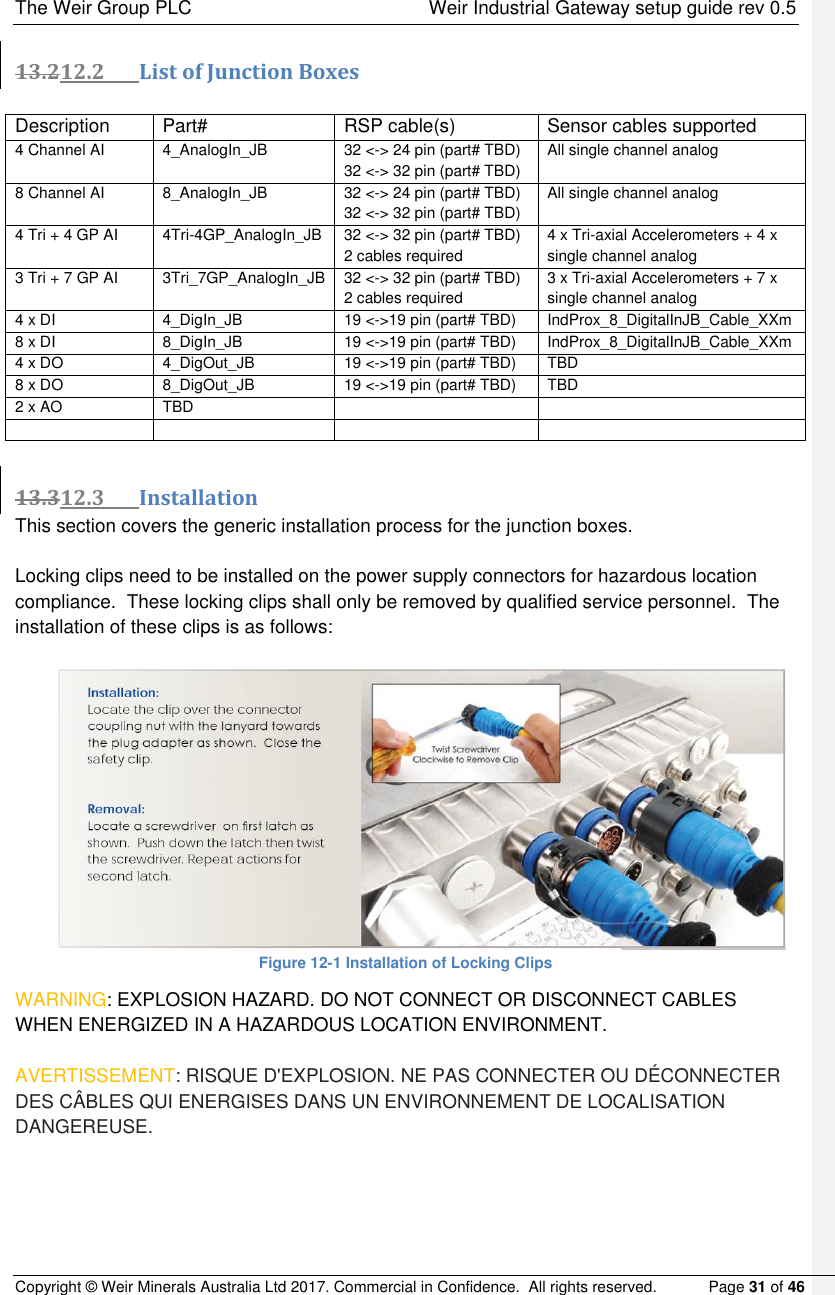
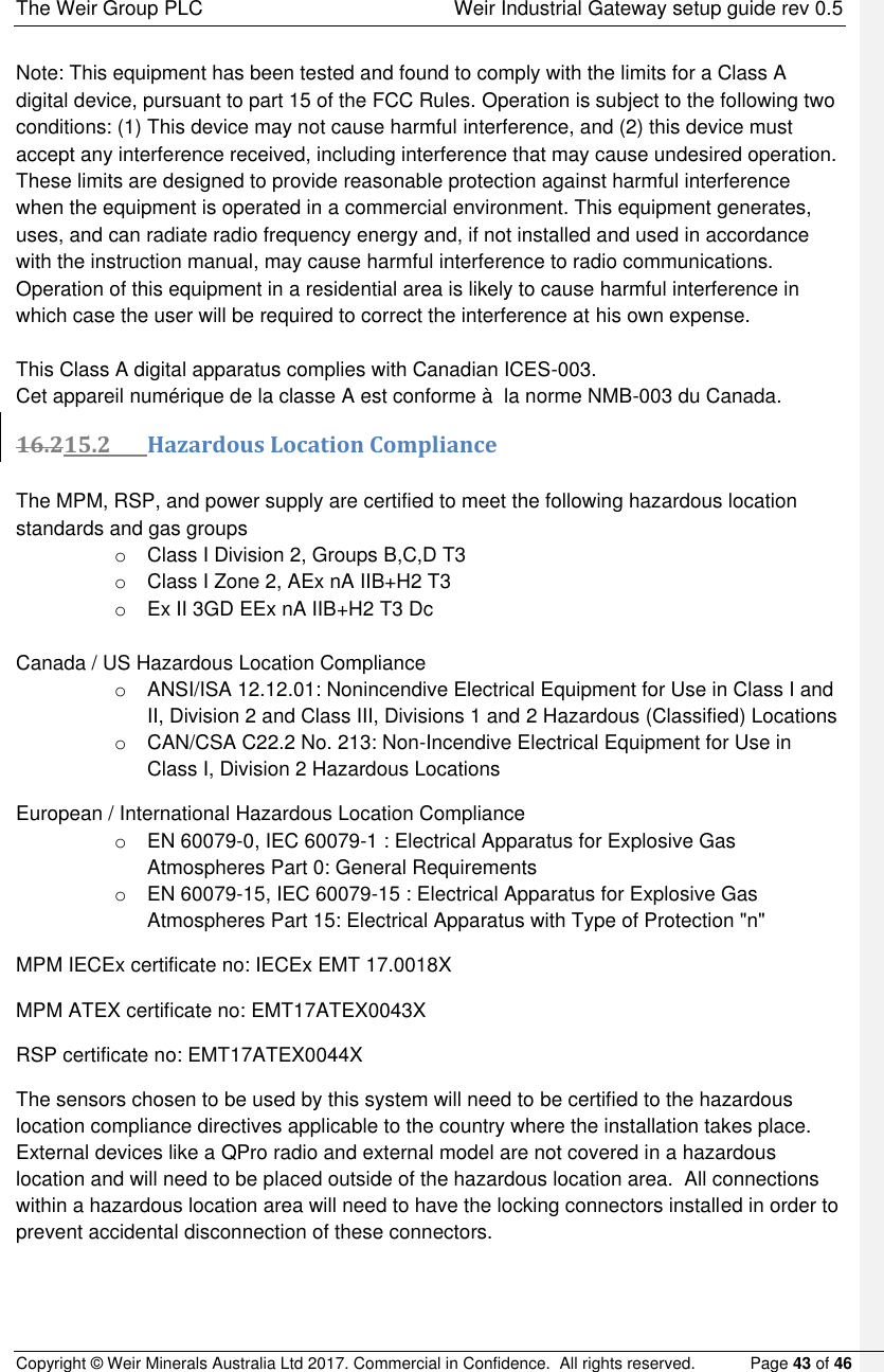
![The Weir Group PLC Weir Industrial Gateway setup guide rev 0.5 Copyright © Weir Minerals Australia Ltd 2017. Commercial in Confidence. All rights reserved. Page 7 of 46 65 PSM – Power Supply Module The PSM is a switch mode power supply that operates of mains AC power and provides the 24Vdc that the whole system operates from. 6.15.1 Parameters relevant to installation and operation o Model # : SPSM-000001 o DELL SKU : IP67IPS500-24 o Supply : 90 to 264 VAC, 47 to 400 Hz o Output: 20A@24Vdc (Nominal 500W) o IP rating : 67 o IK rating : 09 o Hazloc : Certified for Class 1 Div 2 environment o Temperature range (operating) : -30°C ≤ Tamb ≤ 70°C o Mass : 1.587kg o MTBF : > 500,000 hours o Casing material : Powder coated die cast aluminium o Mounting orientation : Connectors facing downwards Figure 5-1 Iso view of PSM Comment [CS1]: Is this a Sanmina part# ?](https://usermanual.wiki/Weir-Group-Management-Services/STXMPM.Setup-guide/User-Guide-3684512-Page-13.png)

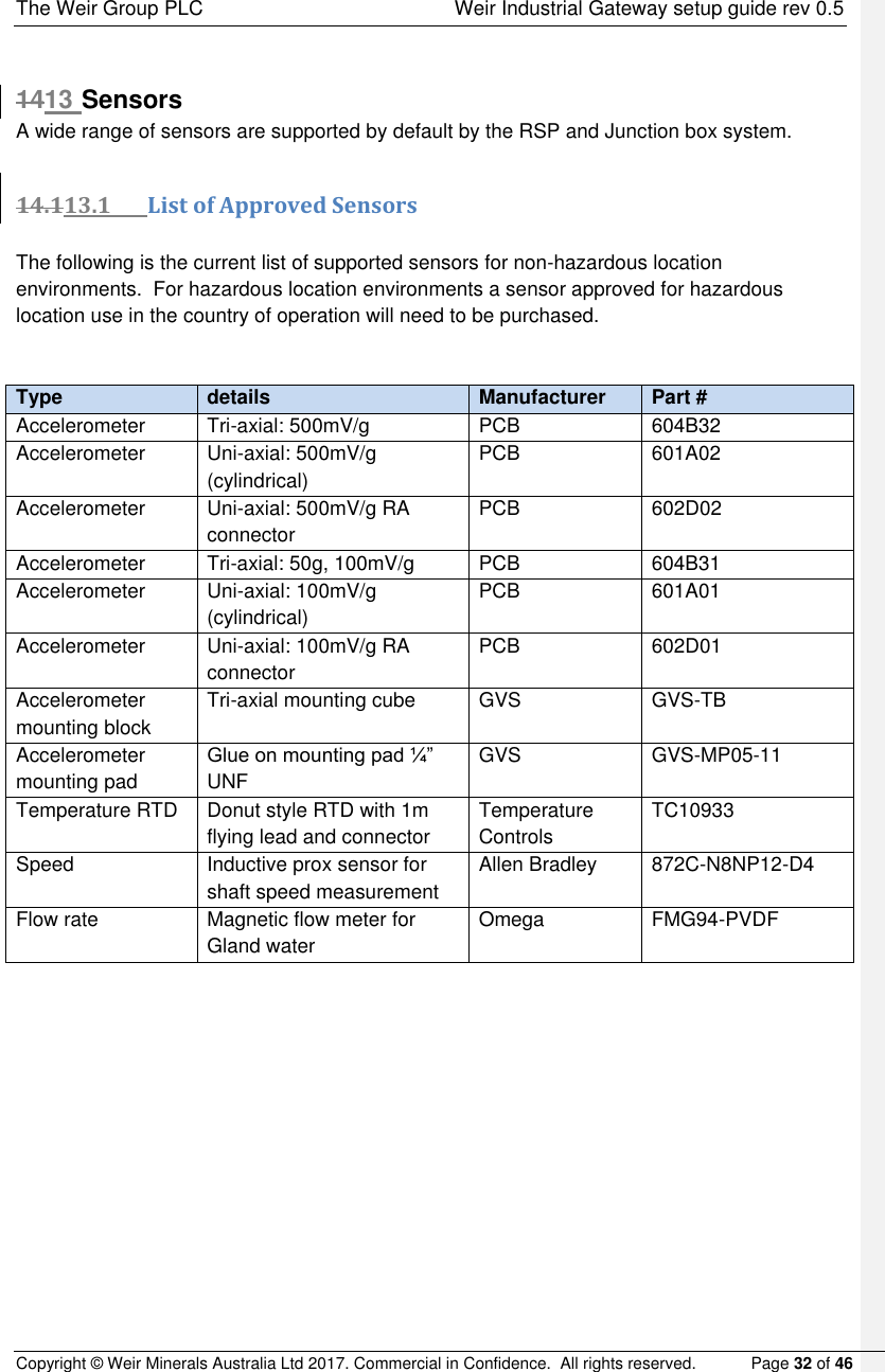
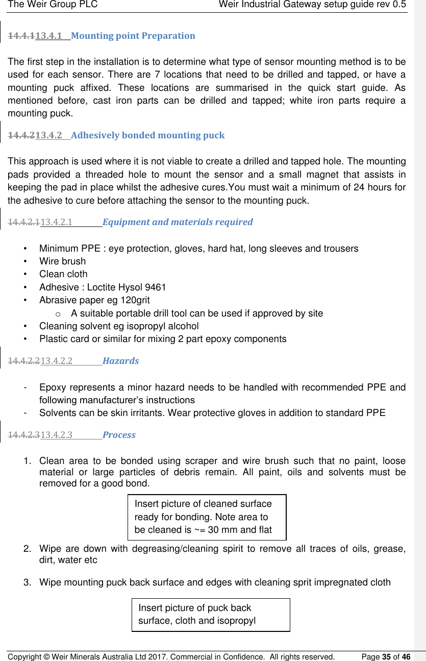
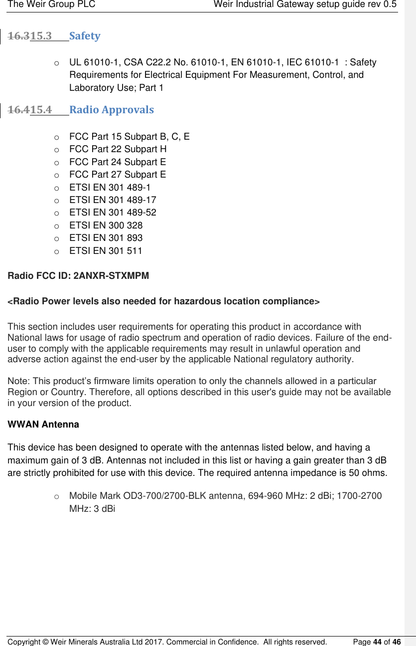
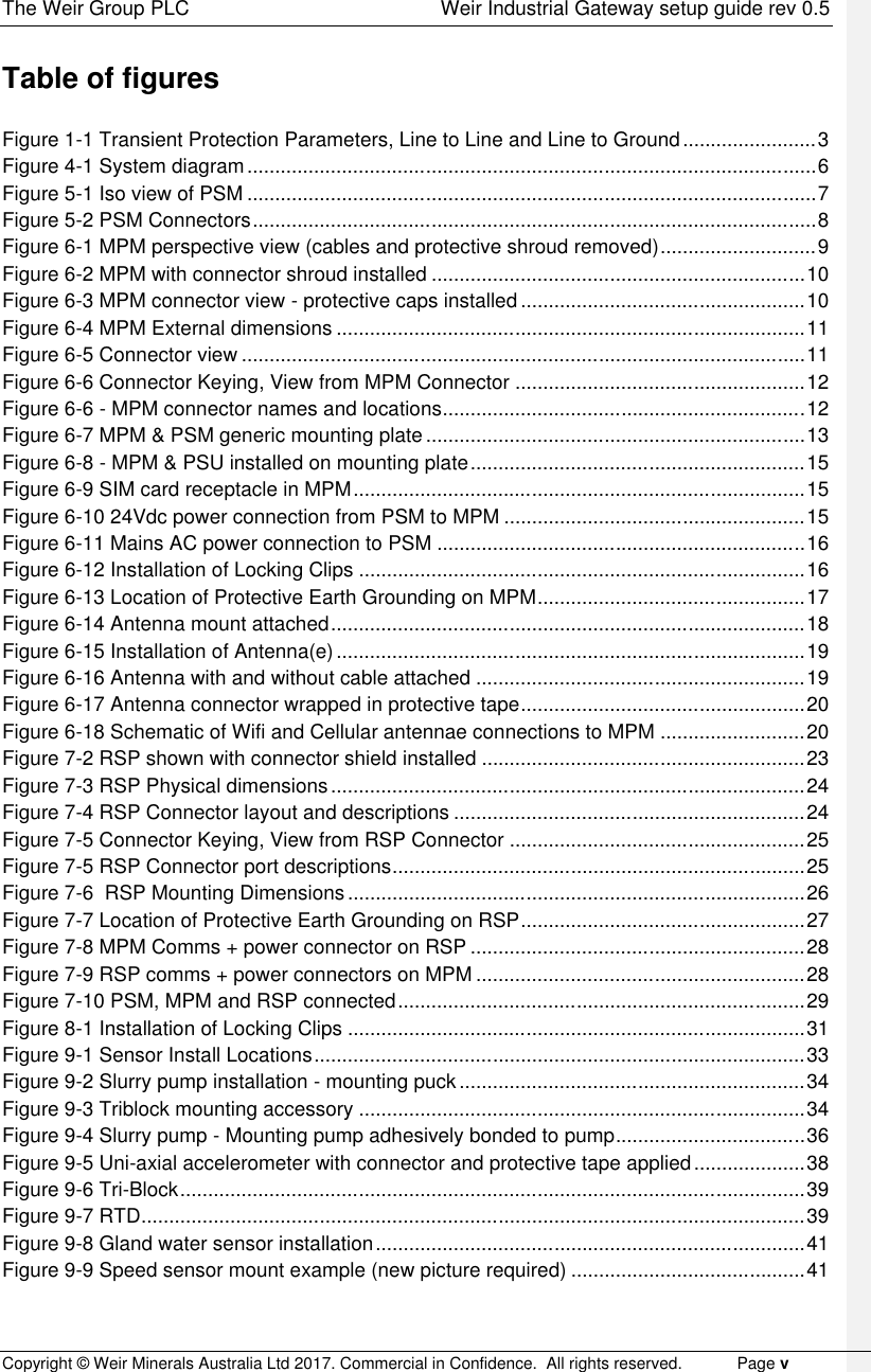
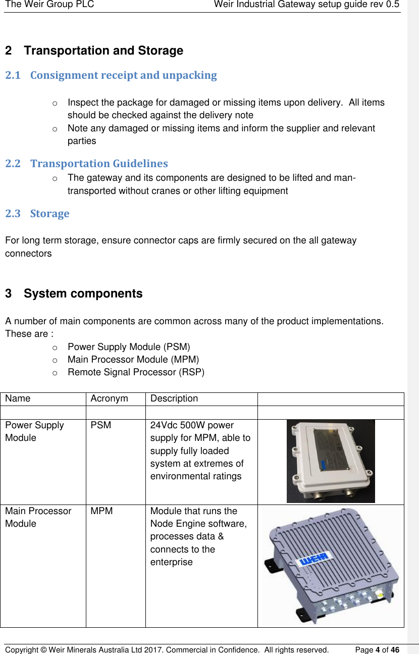
![The Weir Group PLC Weir Industrial Gateway setup guide rev 0.5 Copyright © Weir Minerals Australia Ltd 2017. Commercial in Confidence. All rights reserved. Page 30 of 46 1312 Junction boxes and cables The RSP has a generic signal interface designed to support a wide range of product types. Therefore to match the RSP to any particular product a specific set of cables, junction boxes and sensors are needed. The complete list of junction box types and how they connect to the RSP is described in this section. 13.112.1 List of cables 13.1.112.1.1 Connecting to RSP Description Part # RSP mating connectors Junction box connector type High speed Analog input TBD AI2, AI3 32pin Low speed Analog input TBD AI0, AI1 32 pin Digital Input TBD DI0, DI1, DI2 19 pin Digital output TBD DO0, DO1 19 pin Analog Output TBD AO TBD 13.1.212.1.2 Junction Box to sensor Sensor type Sensor connector Cable Part number (example where XX is length in m) Lengths available (m) Gland water flow meter M12x1 4 pin IndProx_8_DigitalInJB_Cable_XXm 10, 20 Inductive Prox M12x1 4 pin IndProx_8_DigitalInJB_Cable_XXm 10, 20 Uniaxial accelerometer 2 pin Amphenol MS3106F10SL-4S Accel_8_AnalogInJB_Cable_XXm 3, 6, 10, 20 Triaxial accelerometer 4 pin Amphenol PT06W8-4S(SR) TriAccel_8_AnalogInJB_Cable_XXm 10, 20 Glandwater pressure transducer 6 pin Amphenol PT06W10-6S(SR) GlandPressure_8_AnalogJB_Cable_XXm 10 Temperature RTD 3 pin Marlin 1211U 3 PIN MINI JACK 2, 5, 10 Comment [CS2]: Require part numbers from Sanmina](https://usermanual.wiki/Weir-Group-Management-Services/STXMPM.Setup-guide/User-Guide-3684512-Page-36.png)