Zinwave 305-0007 305-0007 Distributed Antenna System Remote Unit User Manual InstallandConfig
Zinwave Ltd 305-0007 Distributed Antenna System Remote Unit InstallandConfig
Zinwave >
Contents
- 1. Users manual
- 2. Users manual 1
- 3. Users manual 2
- 4. Users manual 3
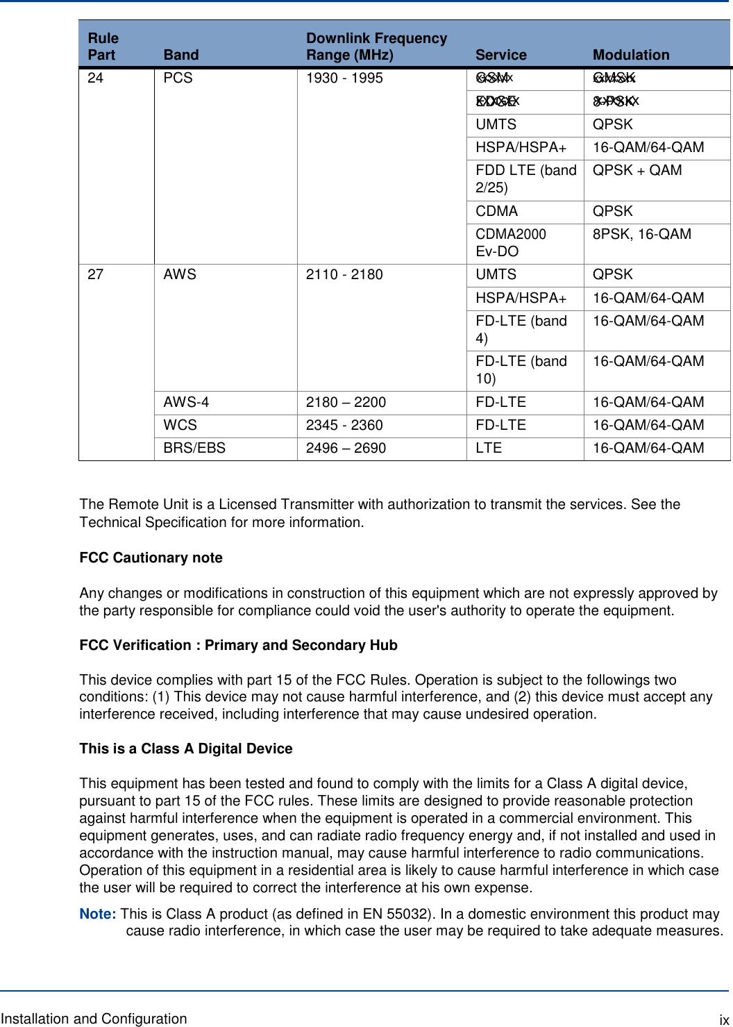
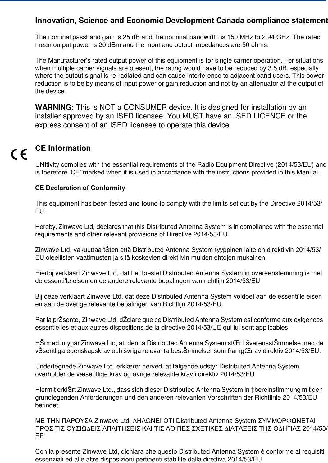
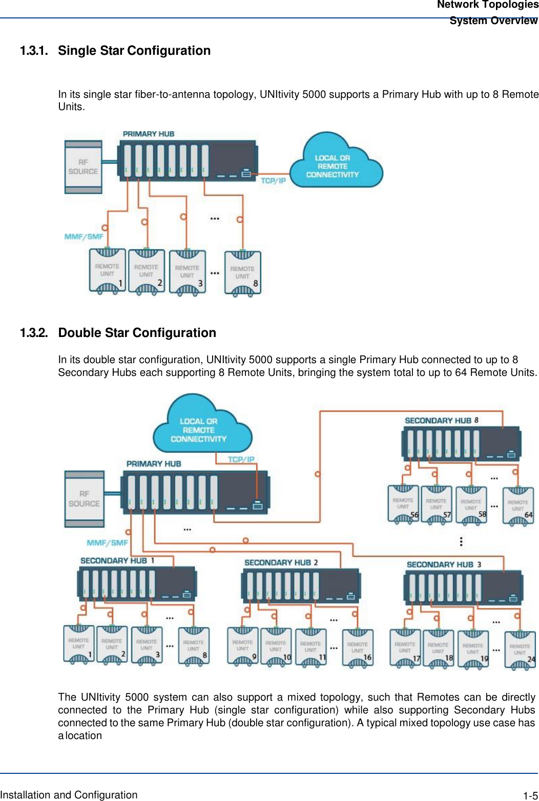
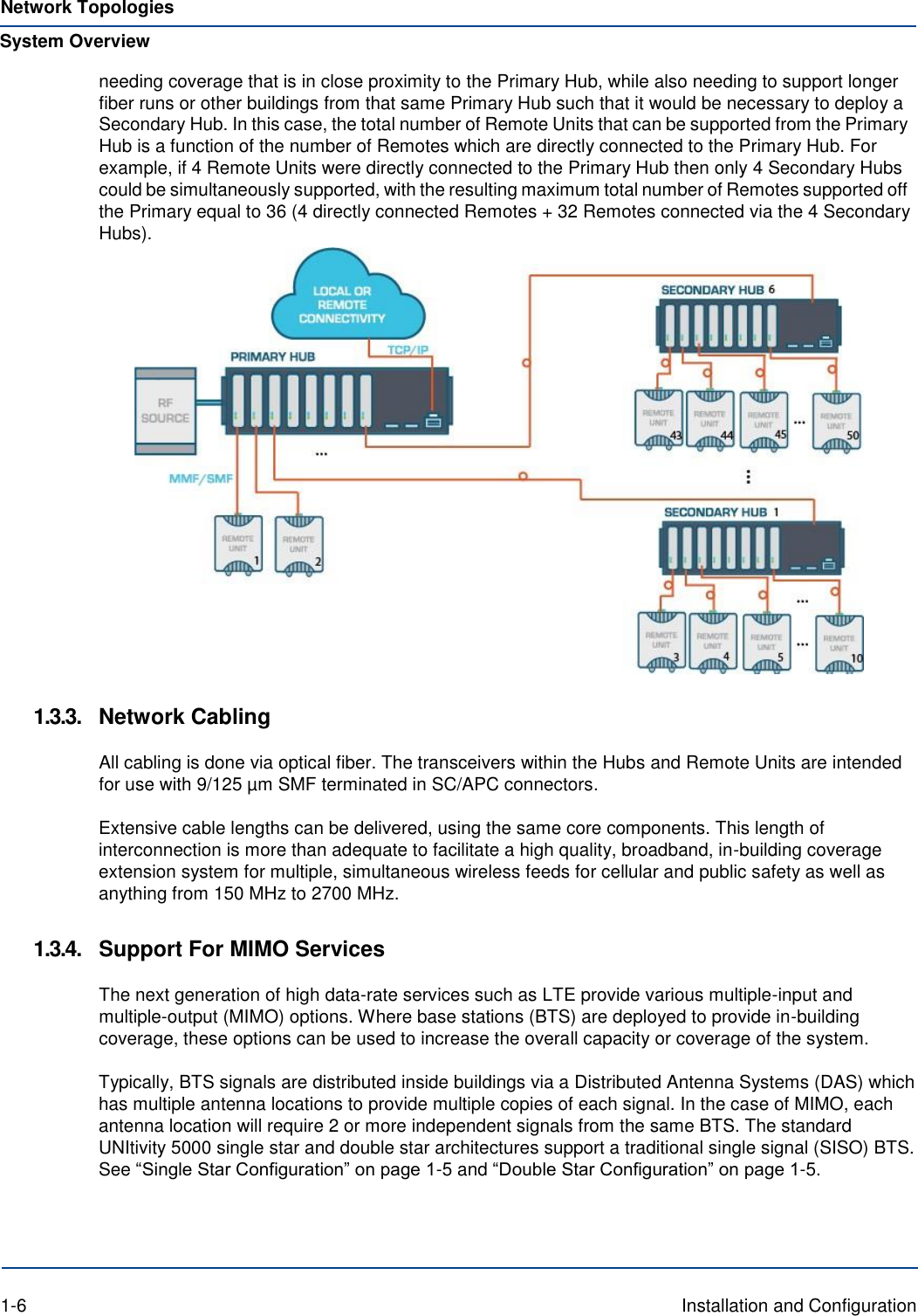
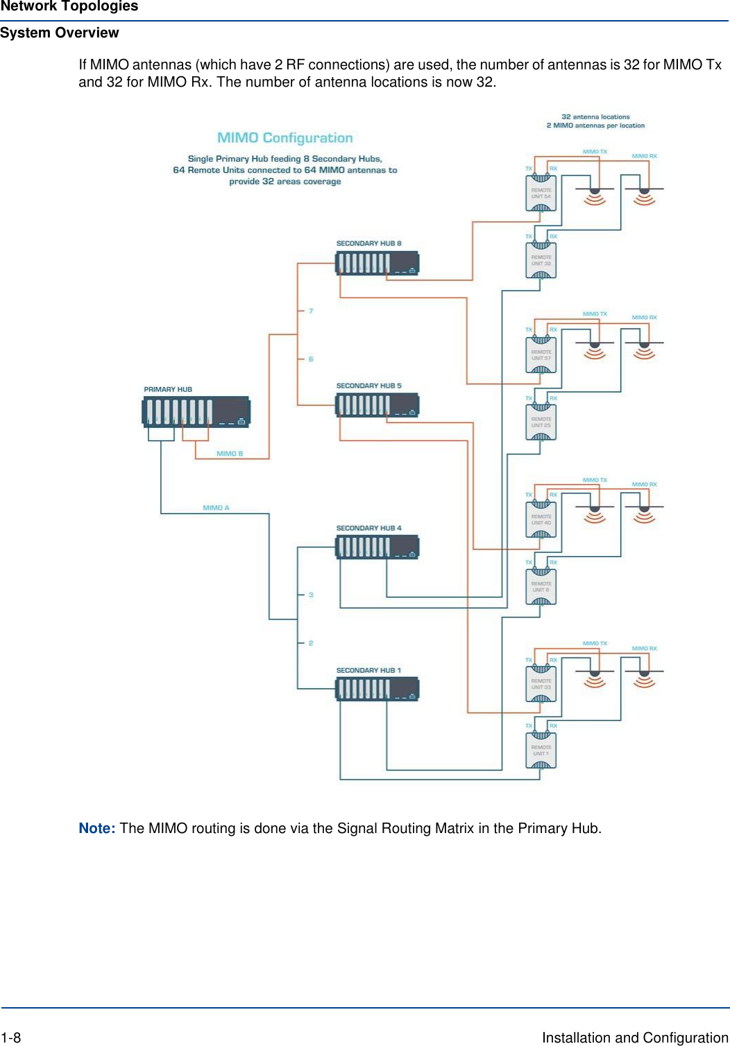
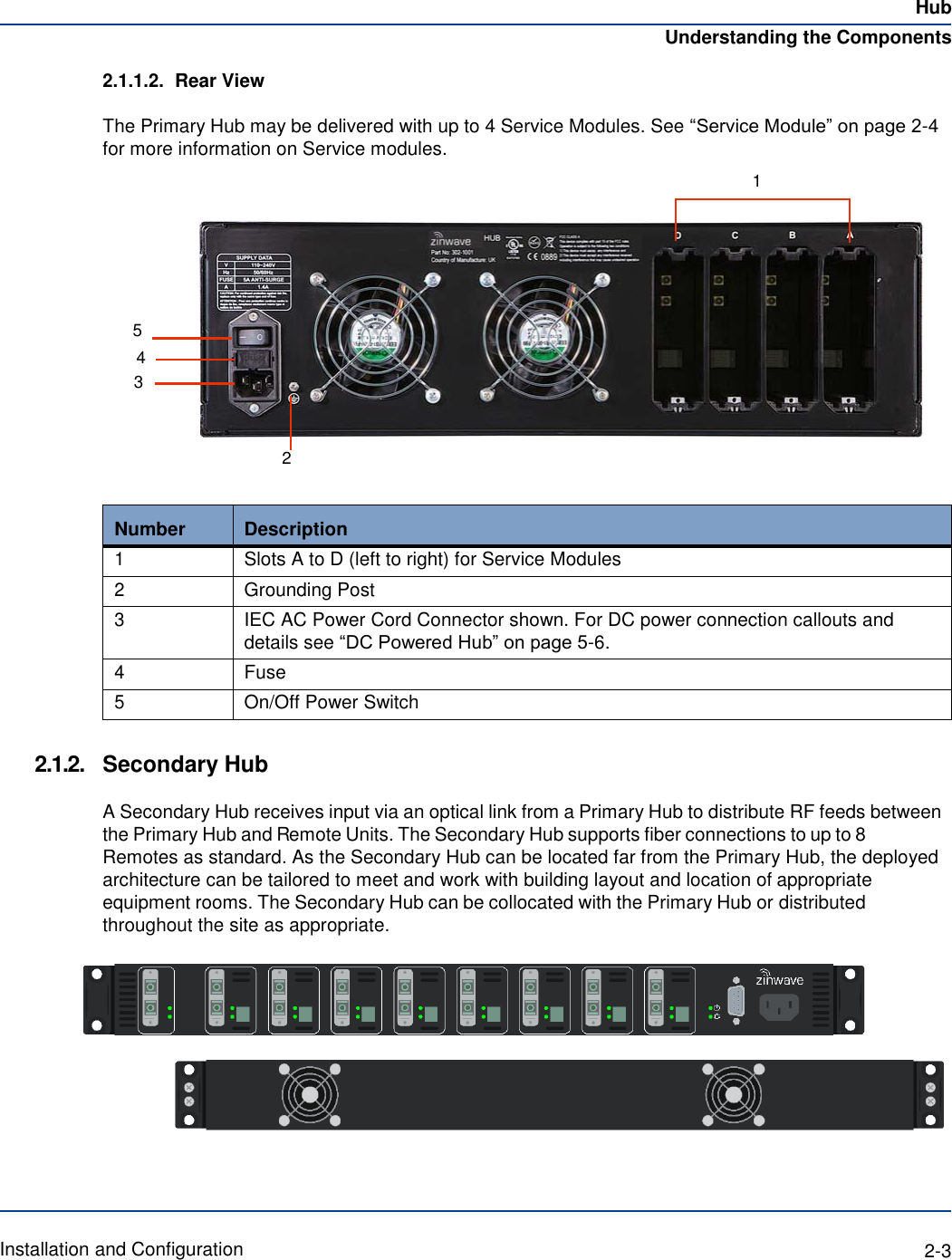
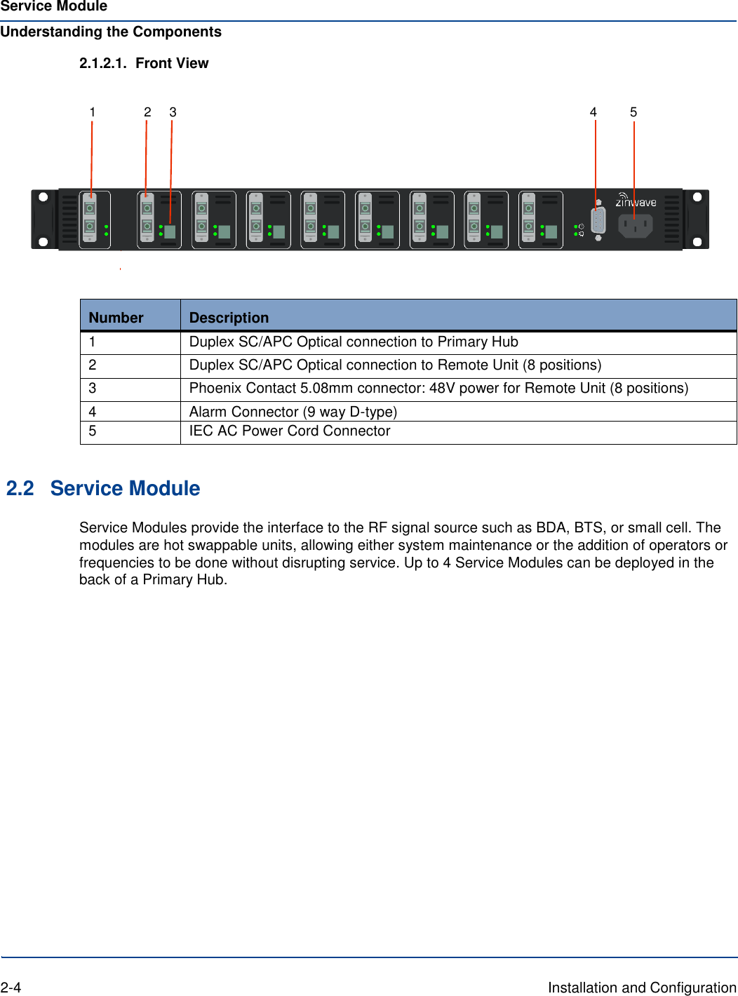
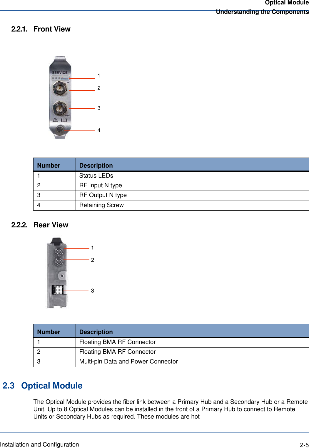
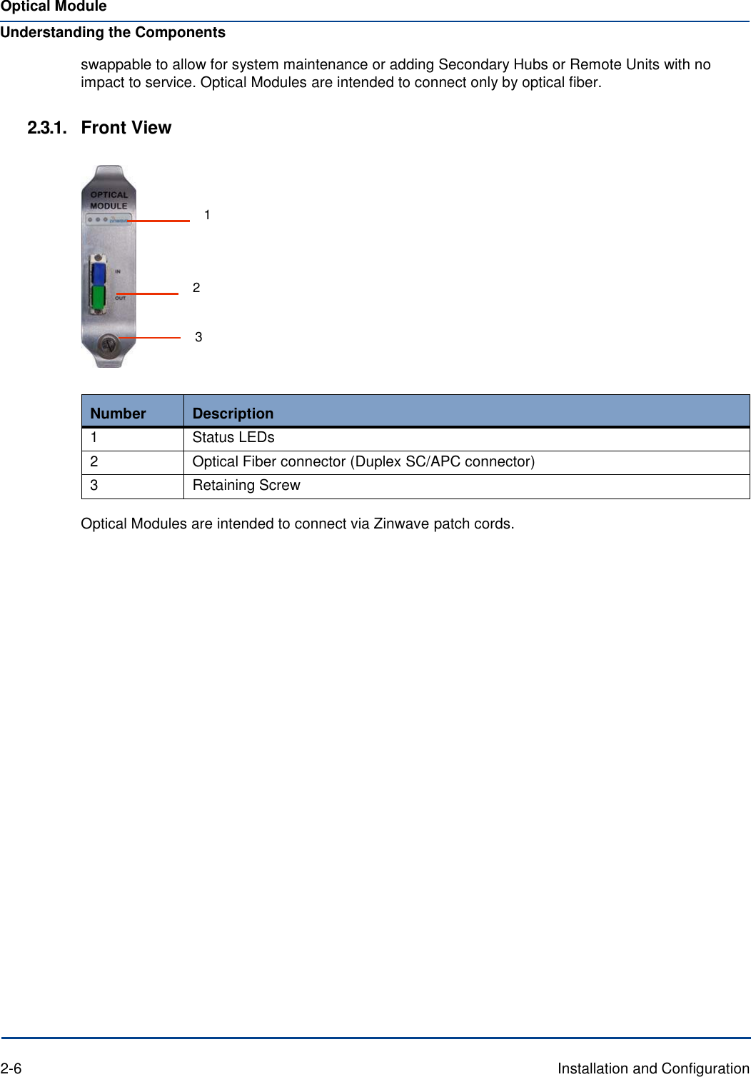
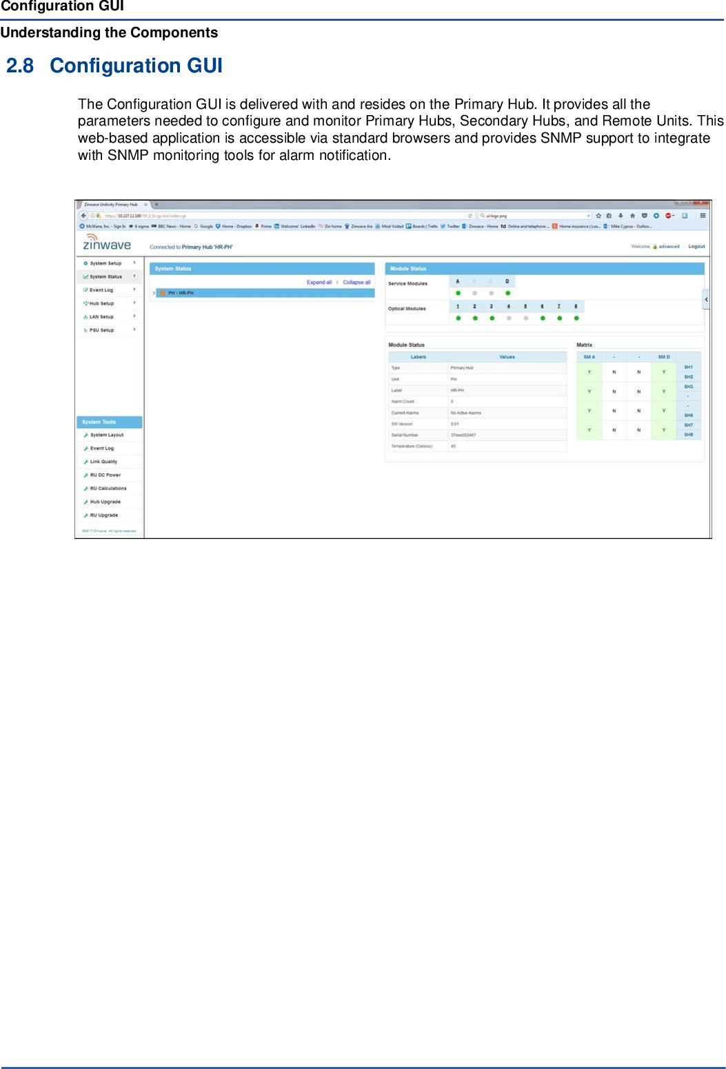
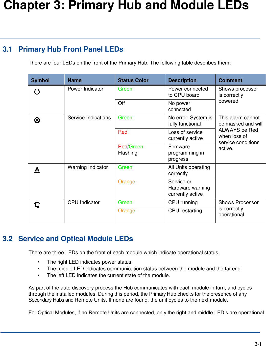
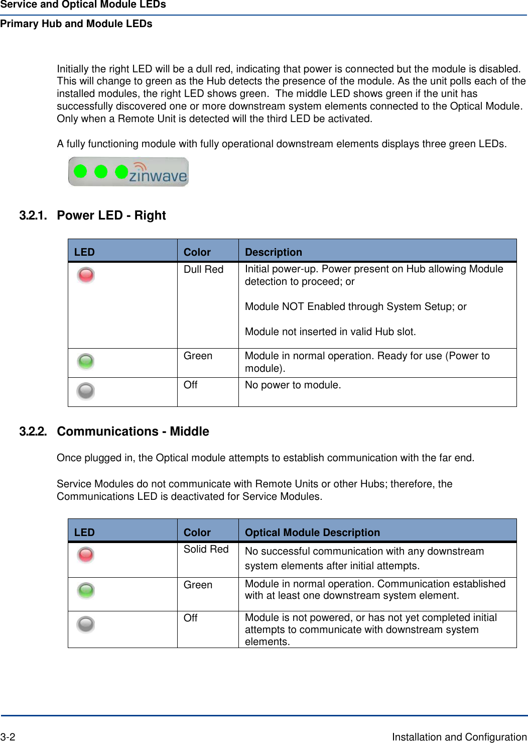
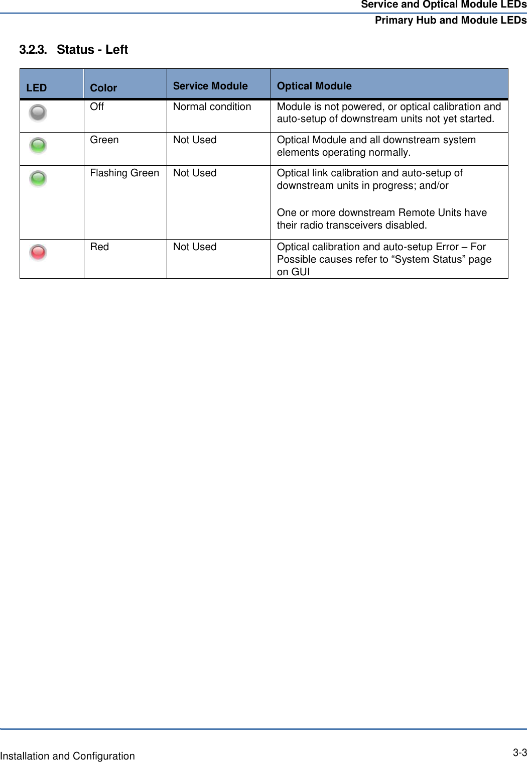
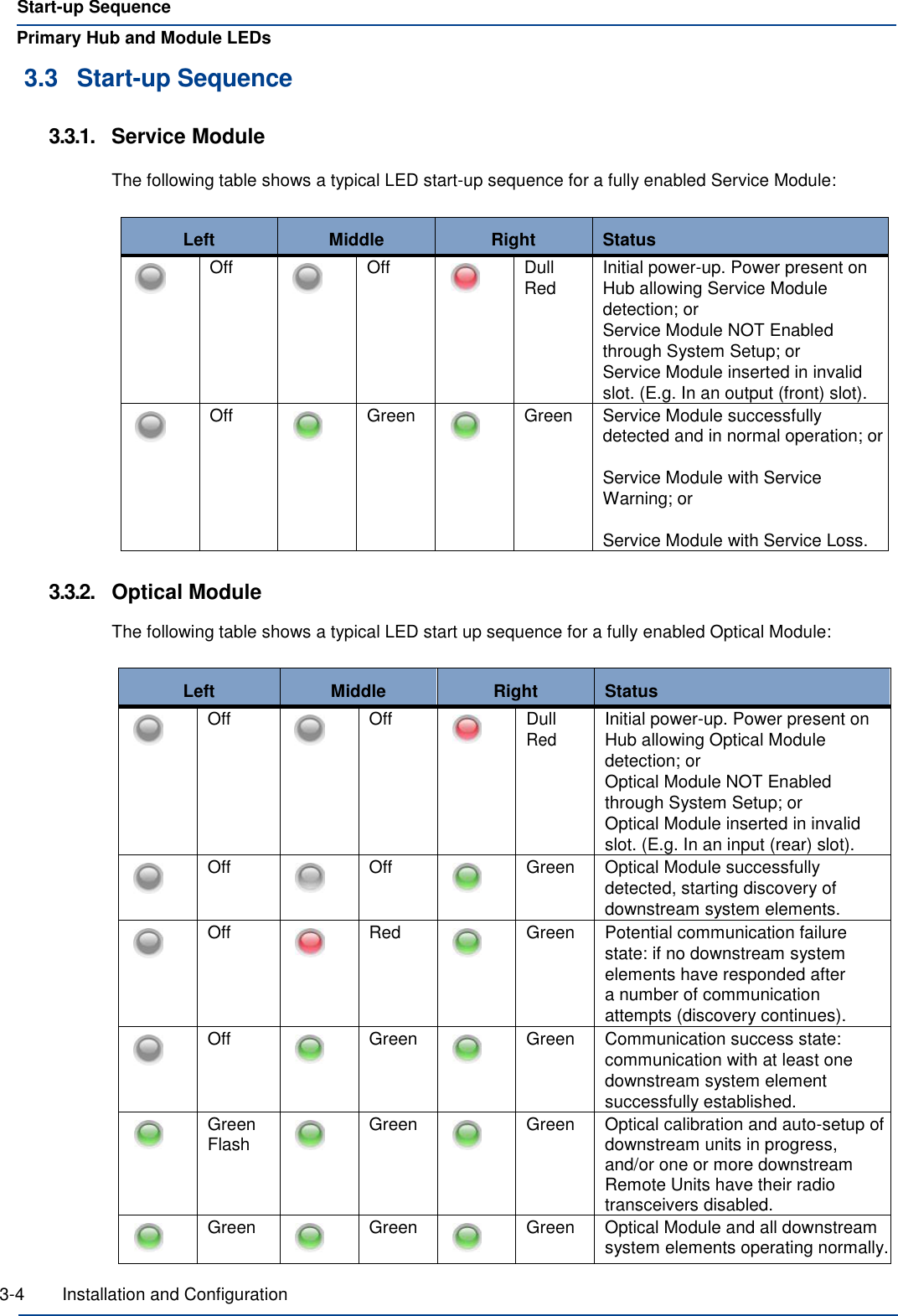
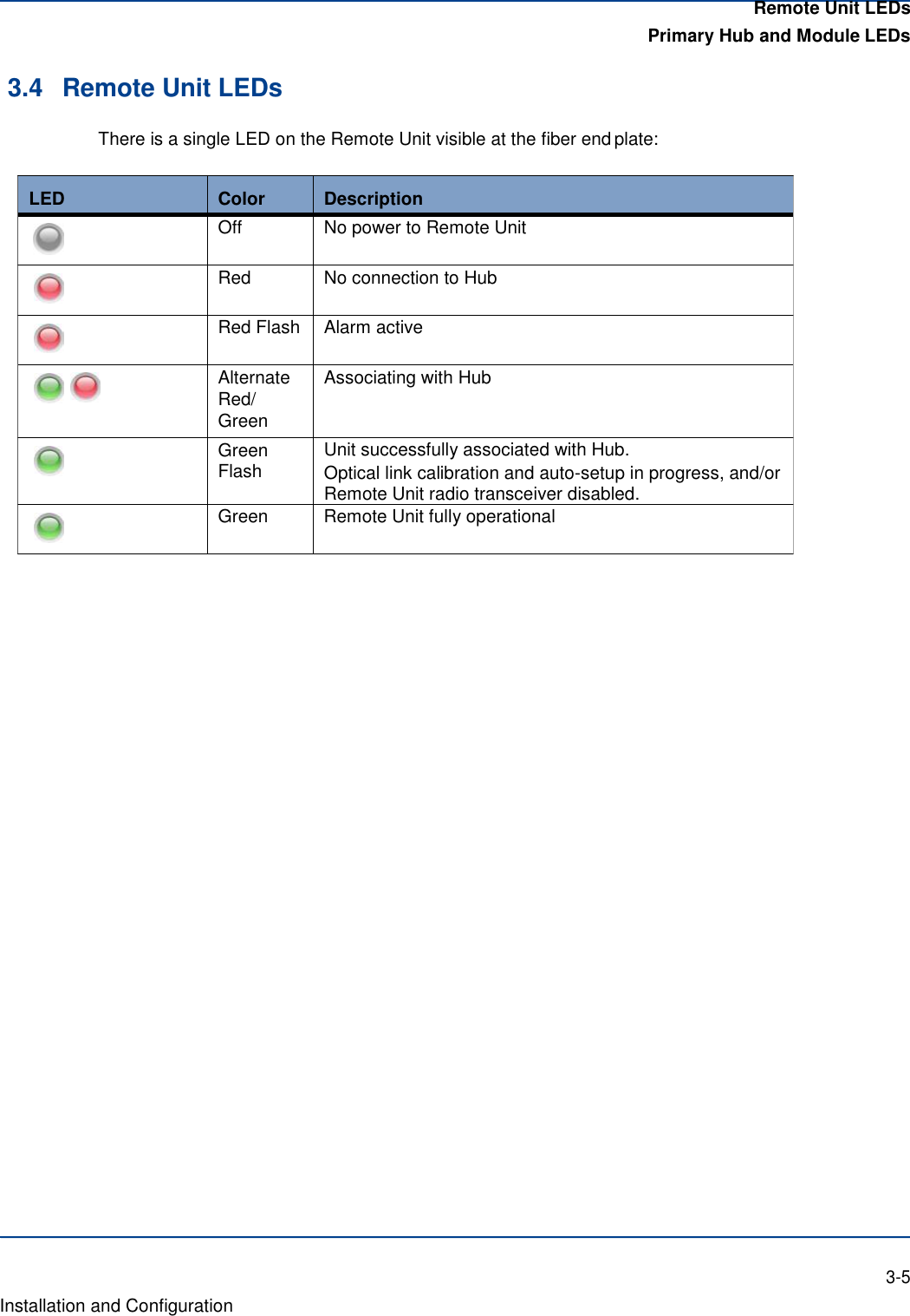
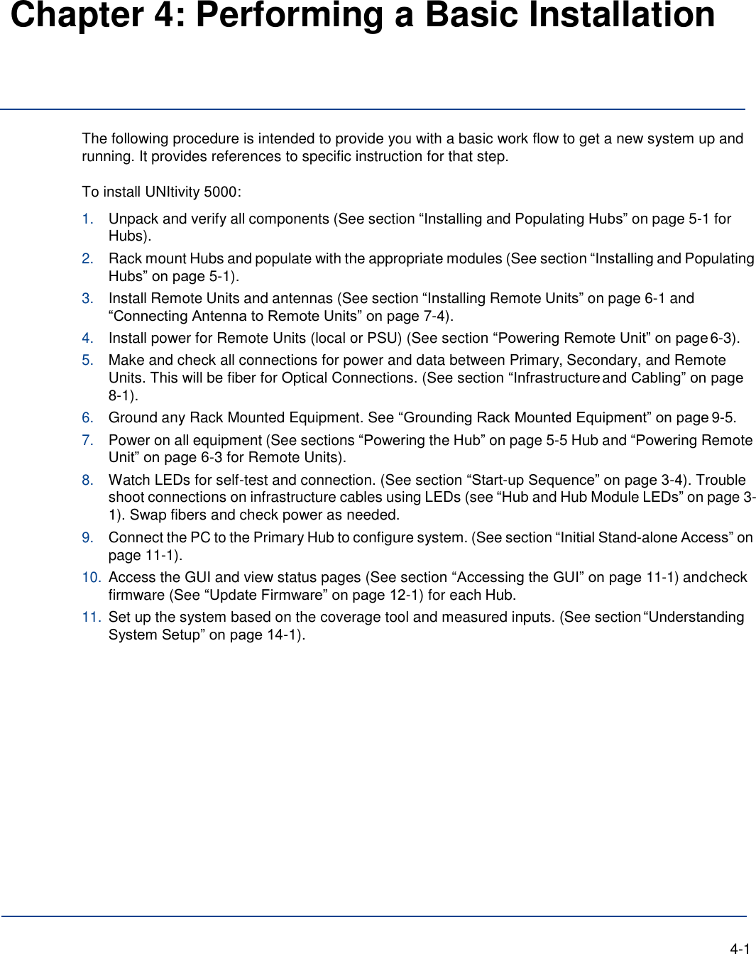
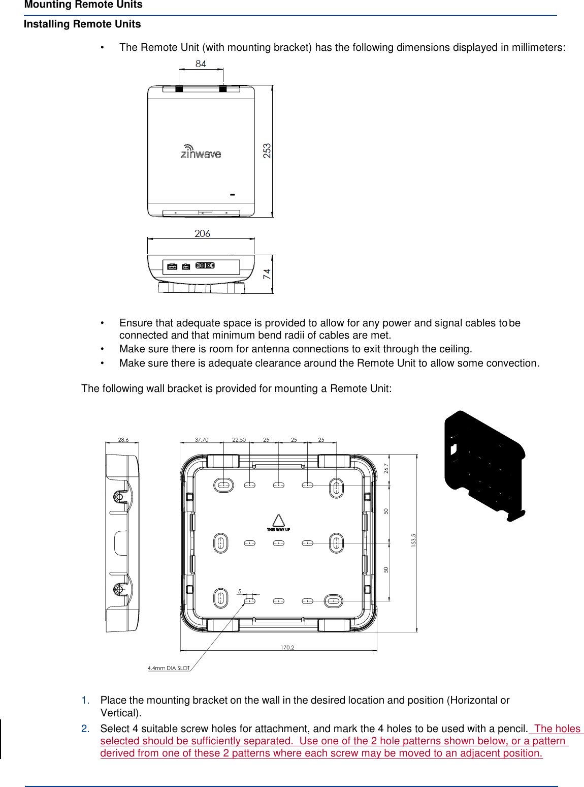
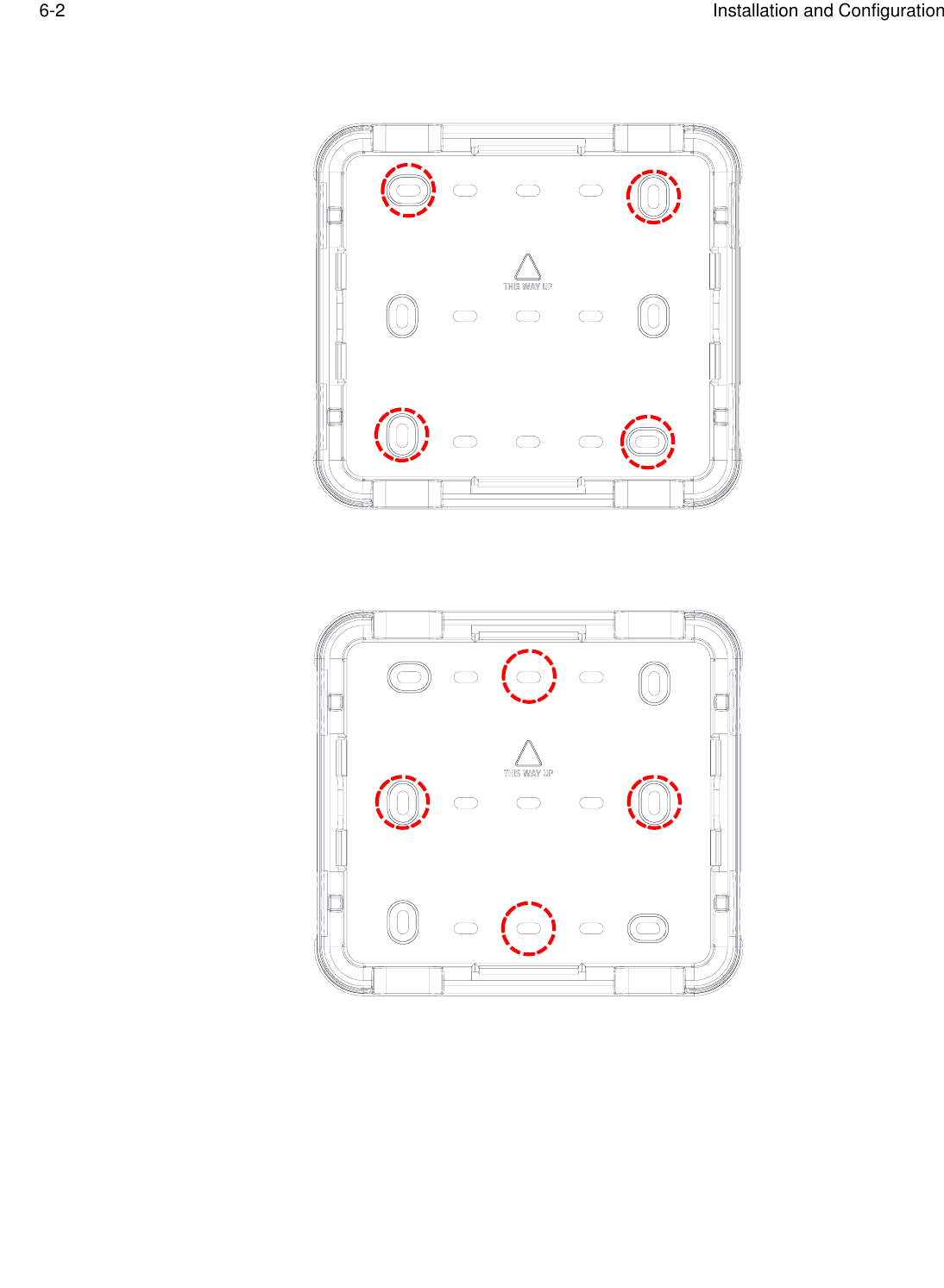
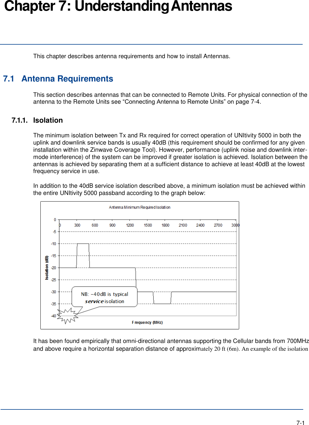
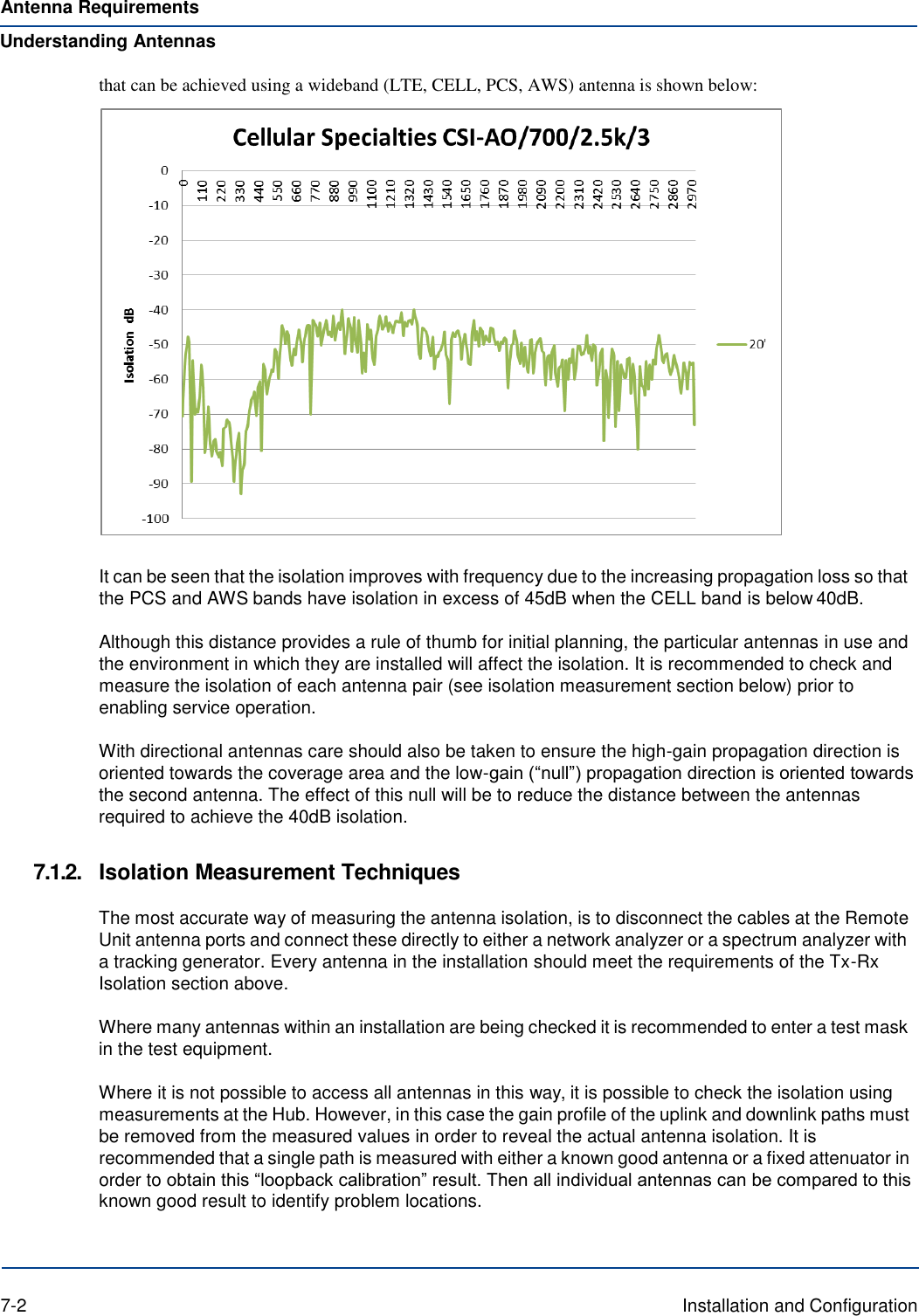
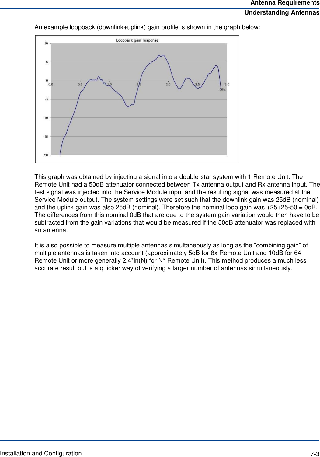
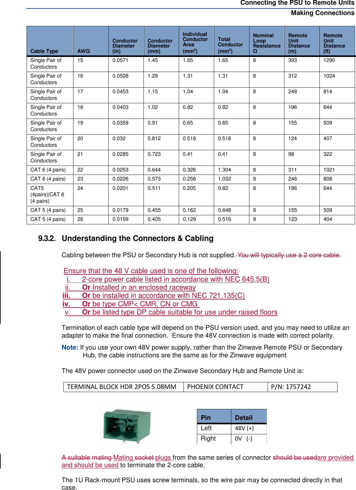
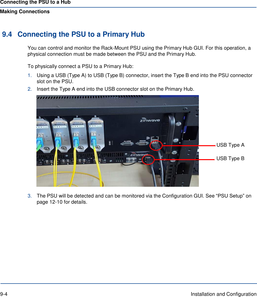
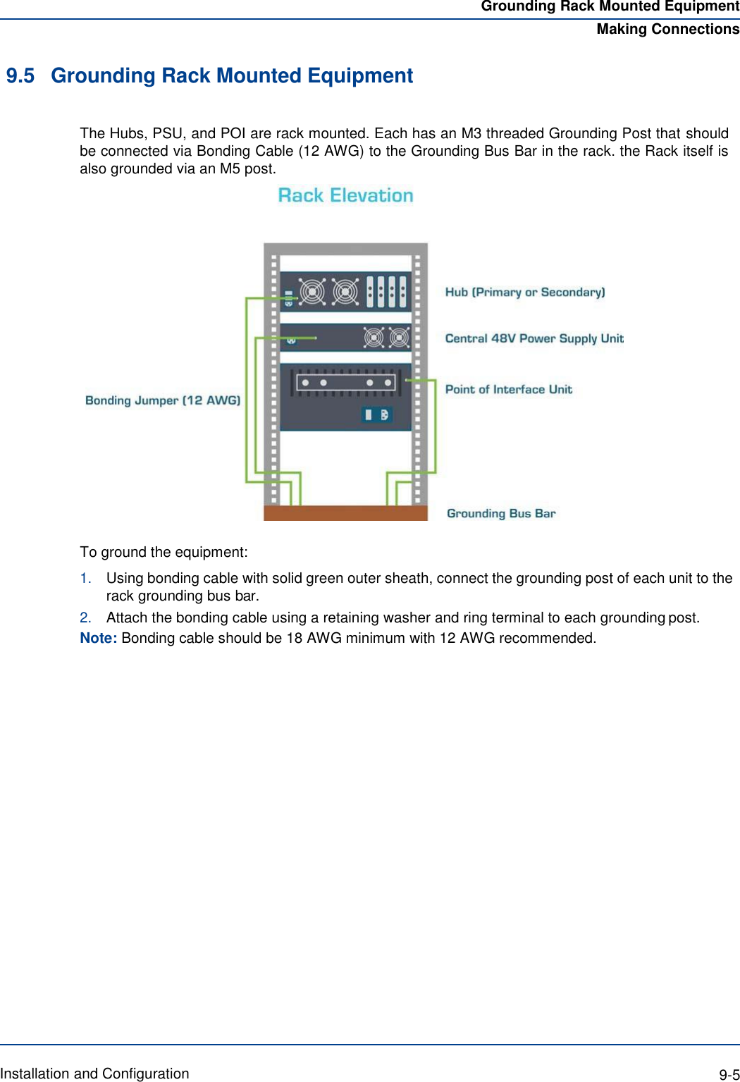
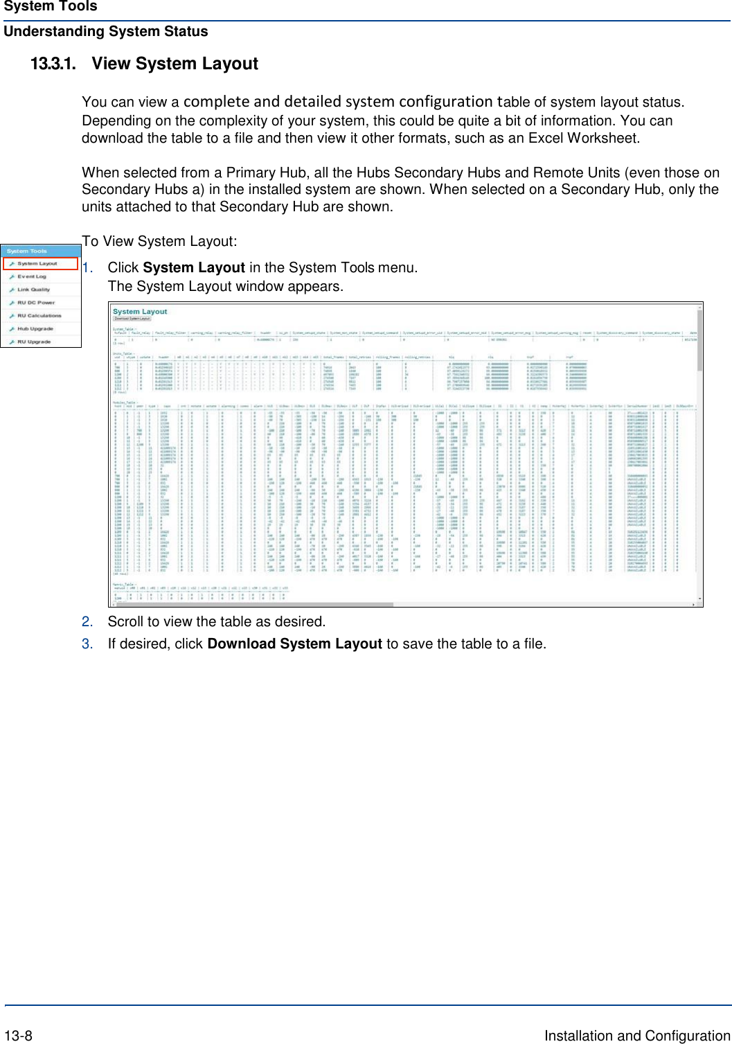
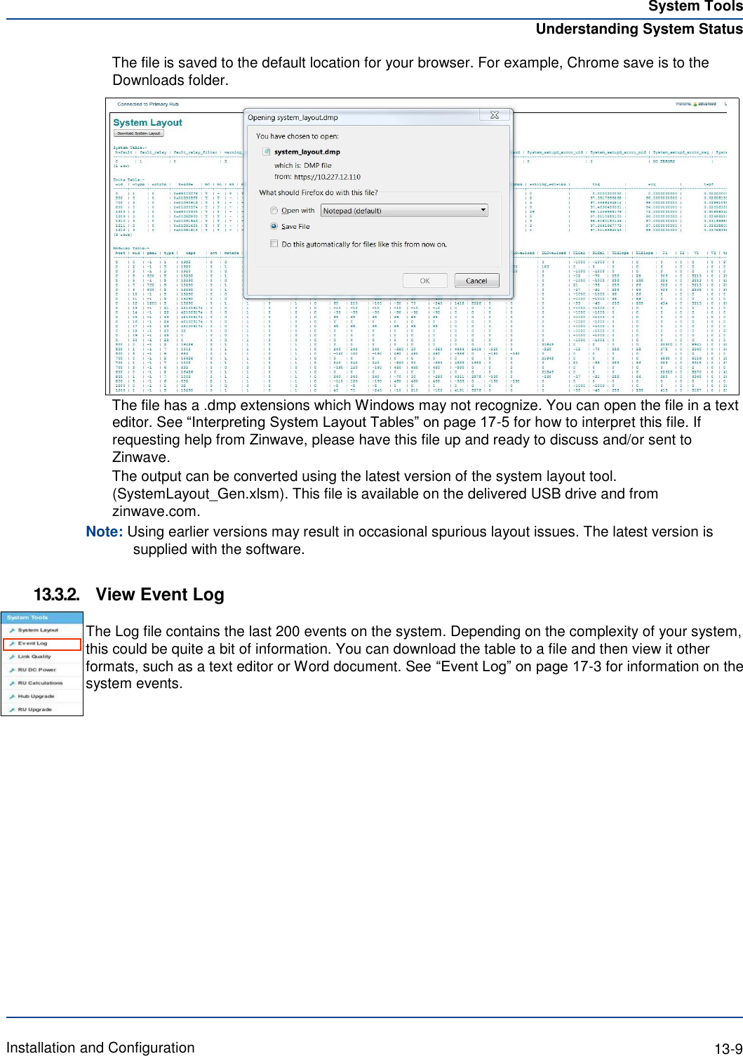
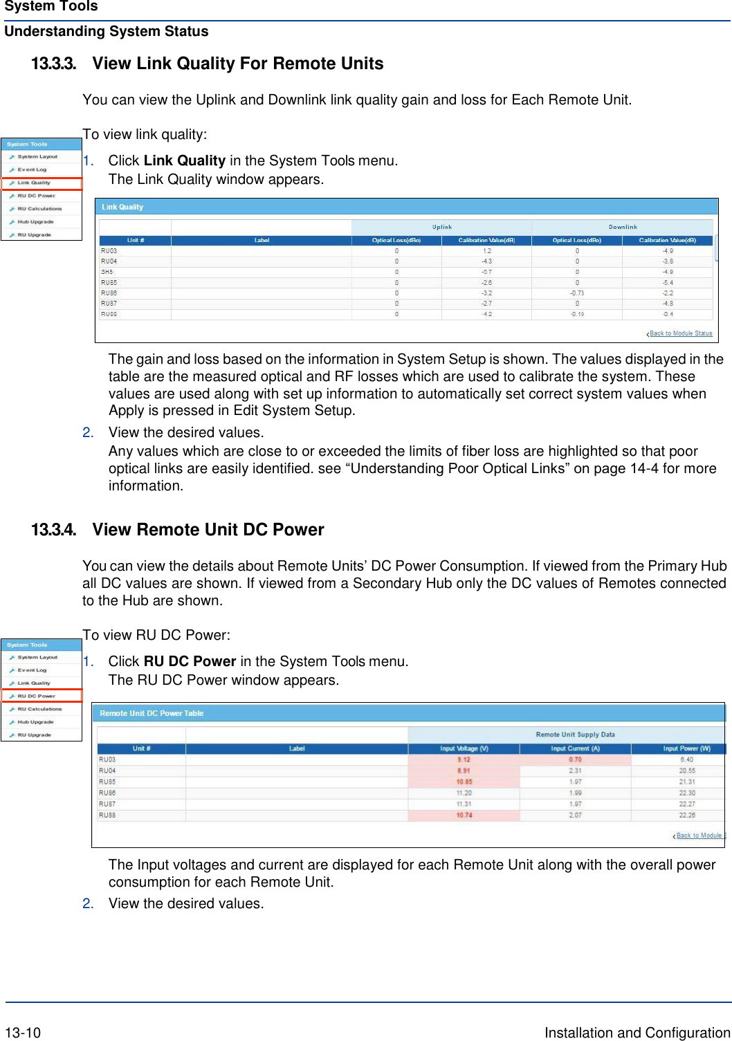
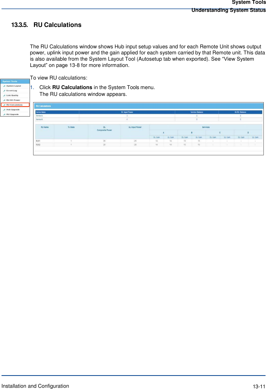
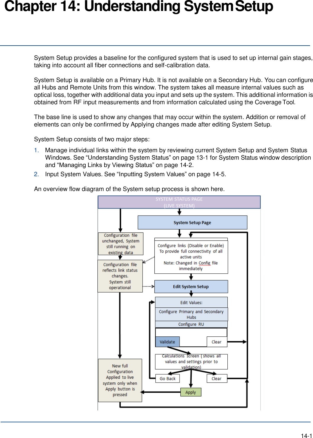
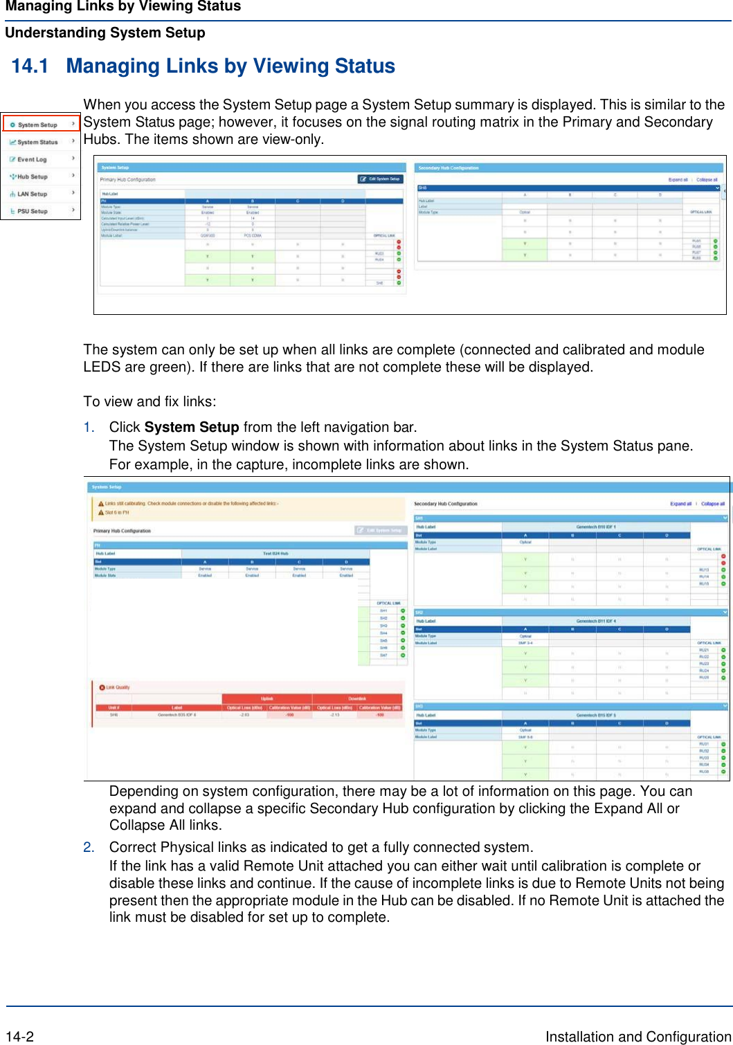
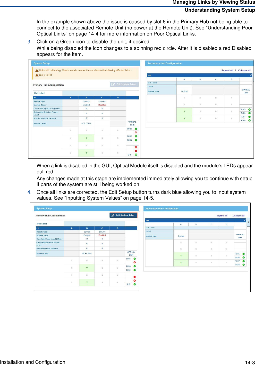
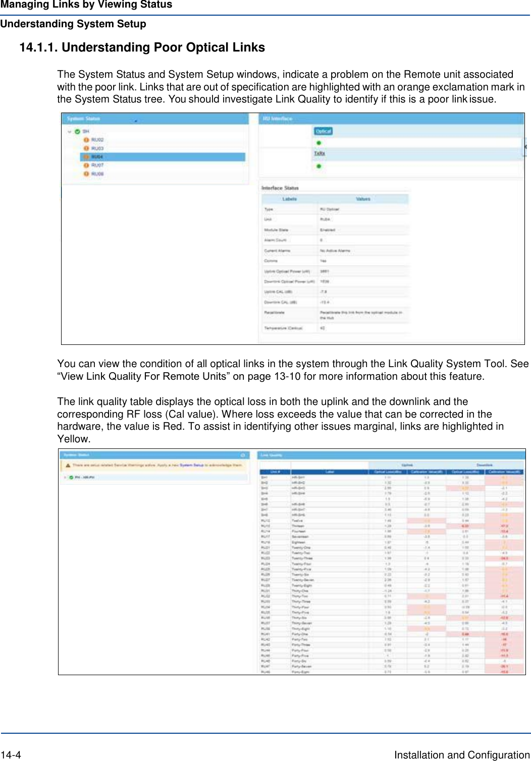
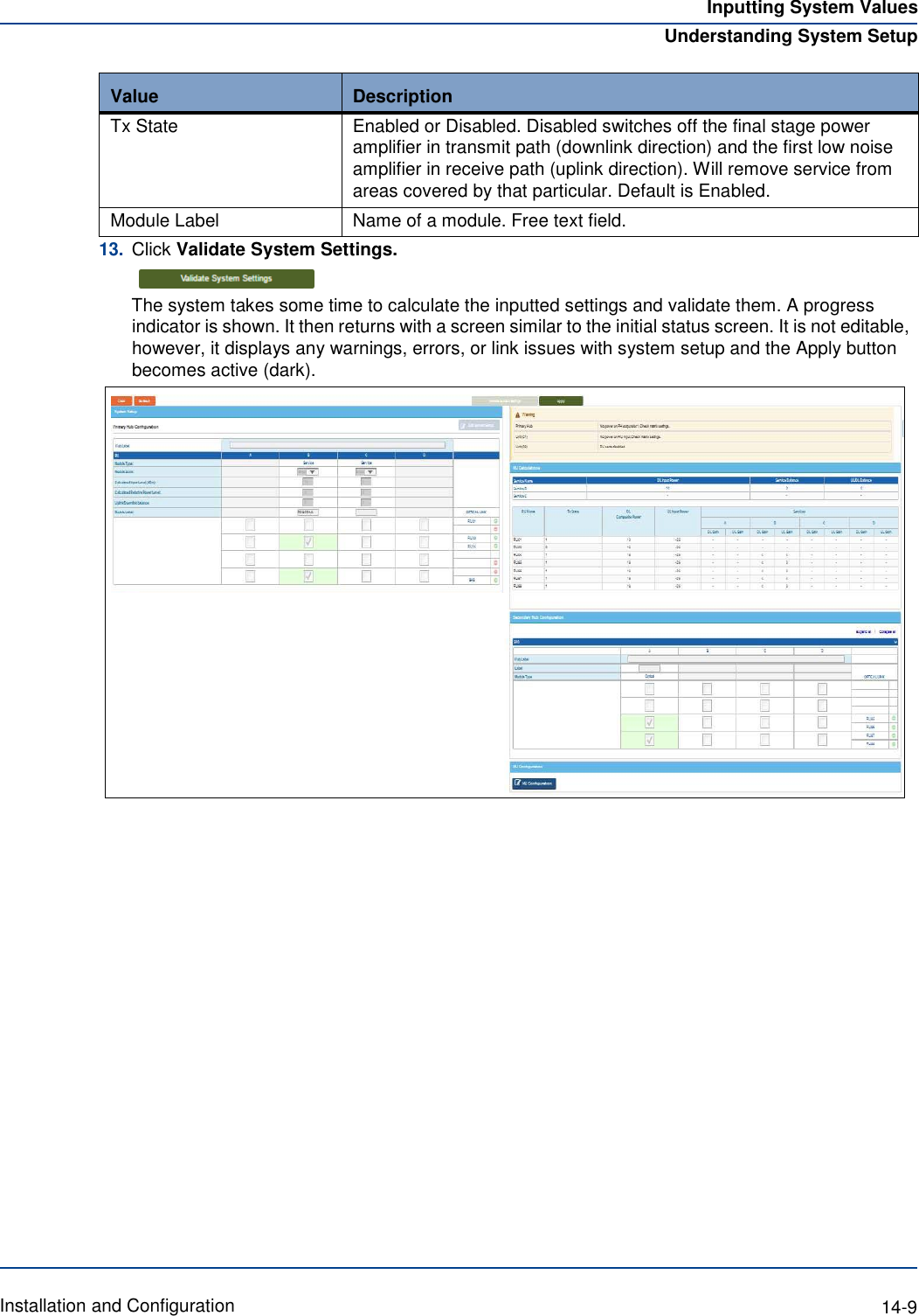
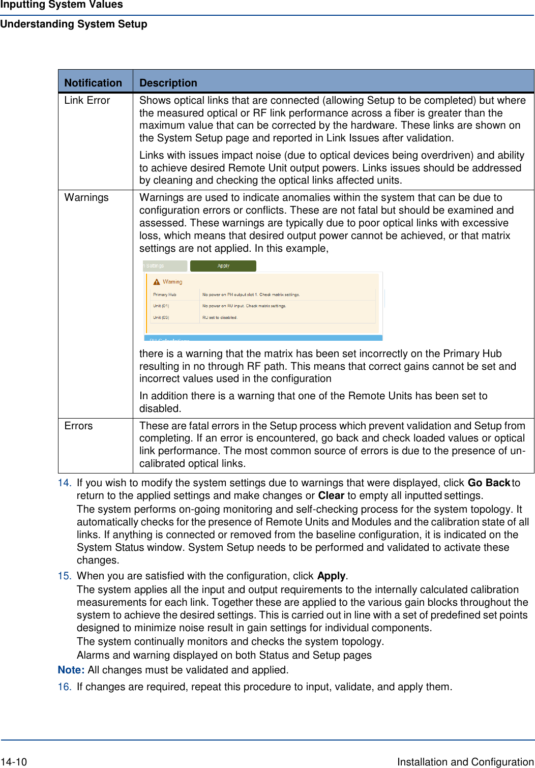
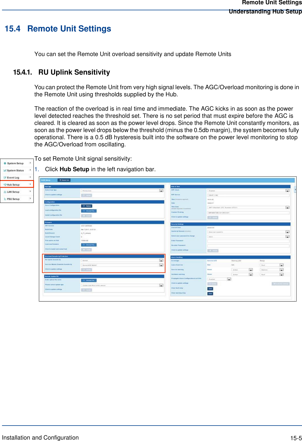
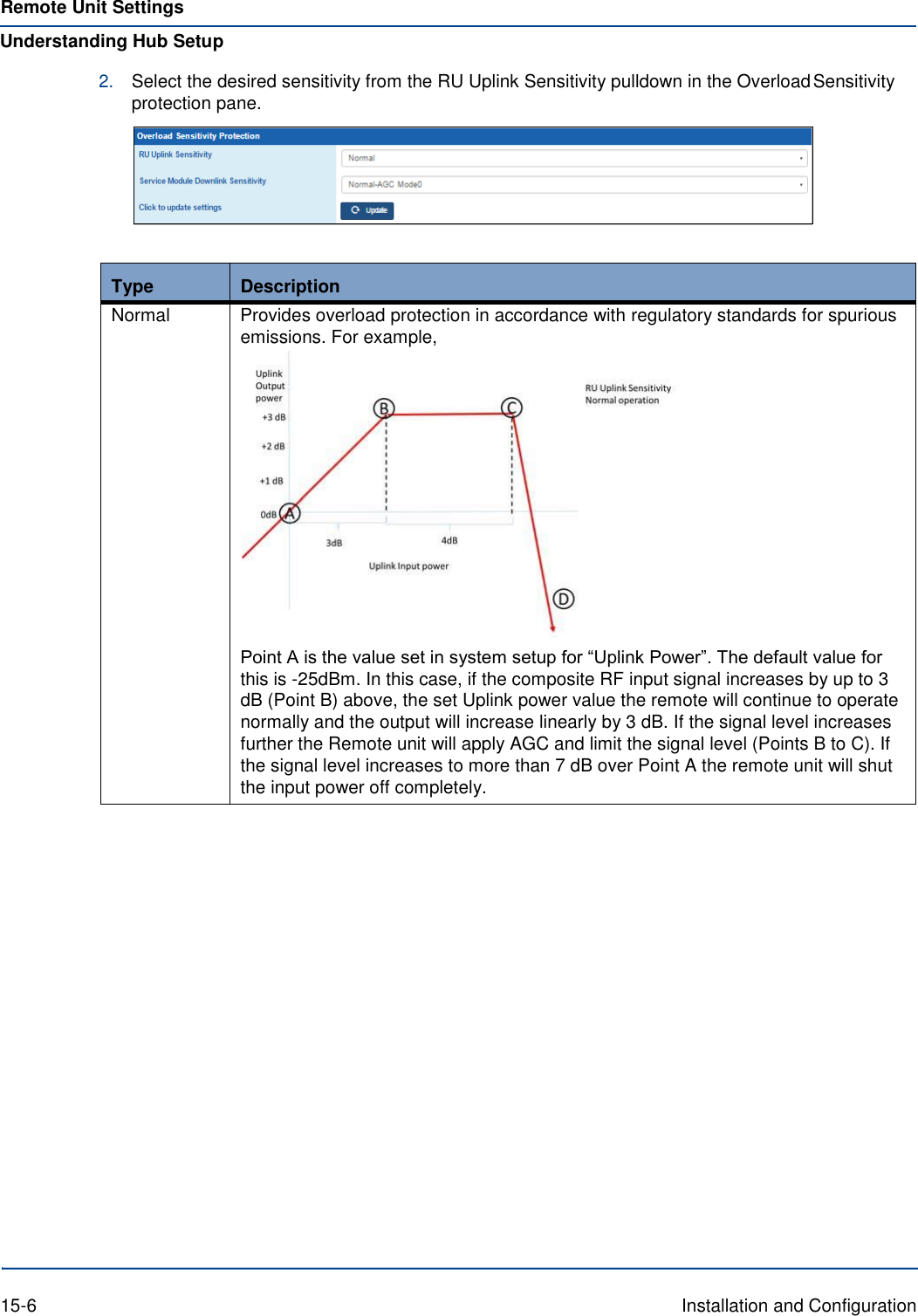
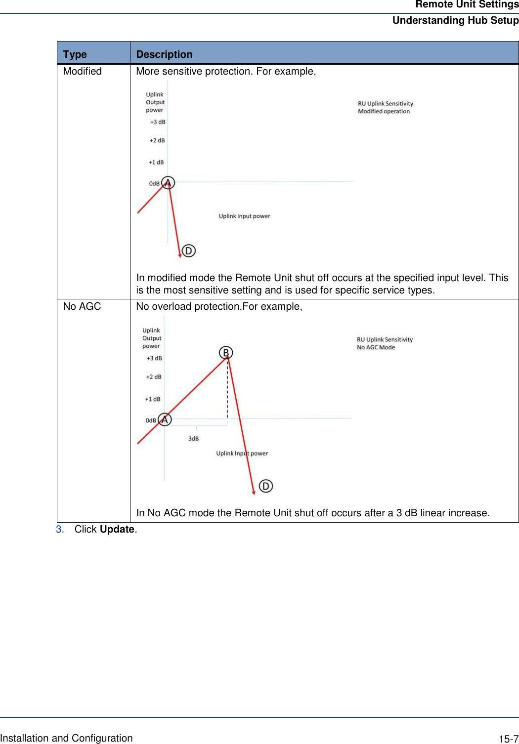
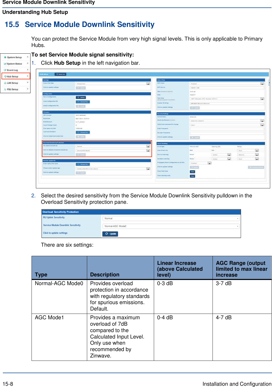
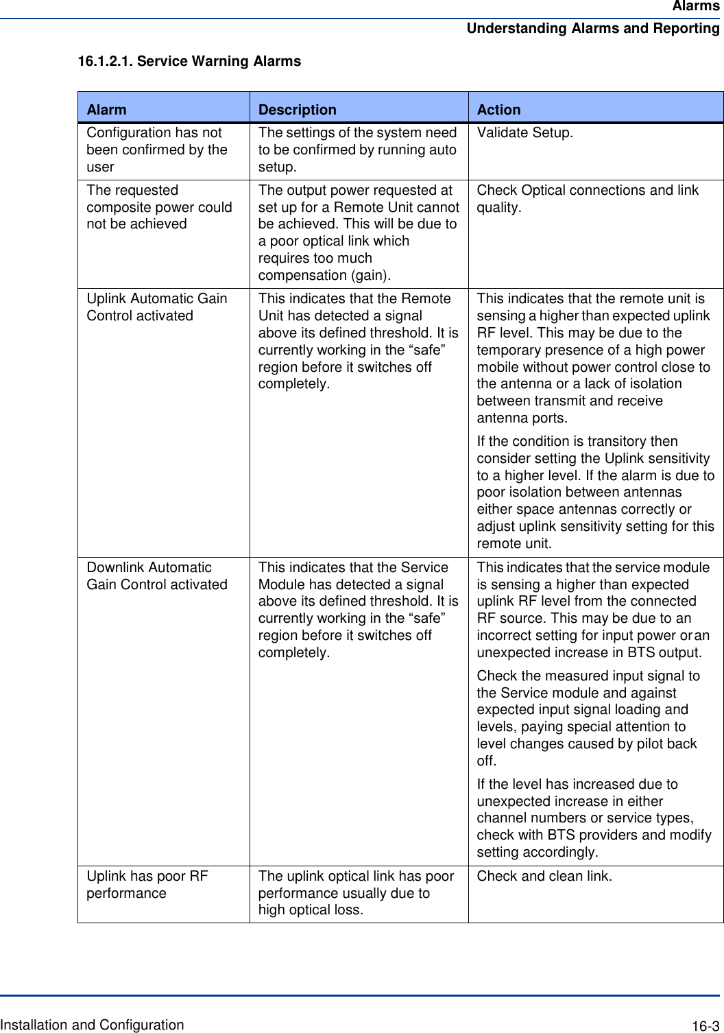
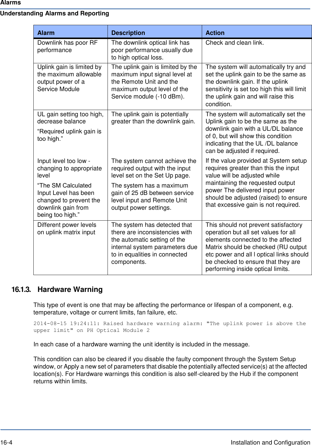
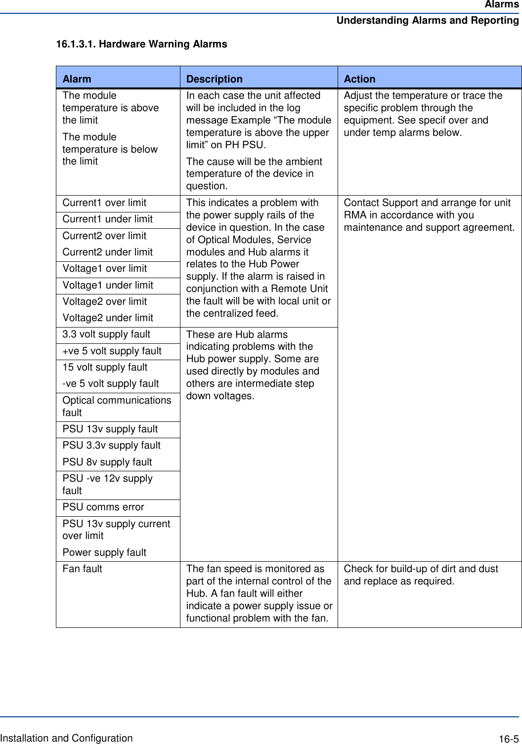
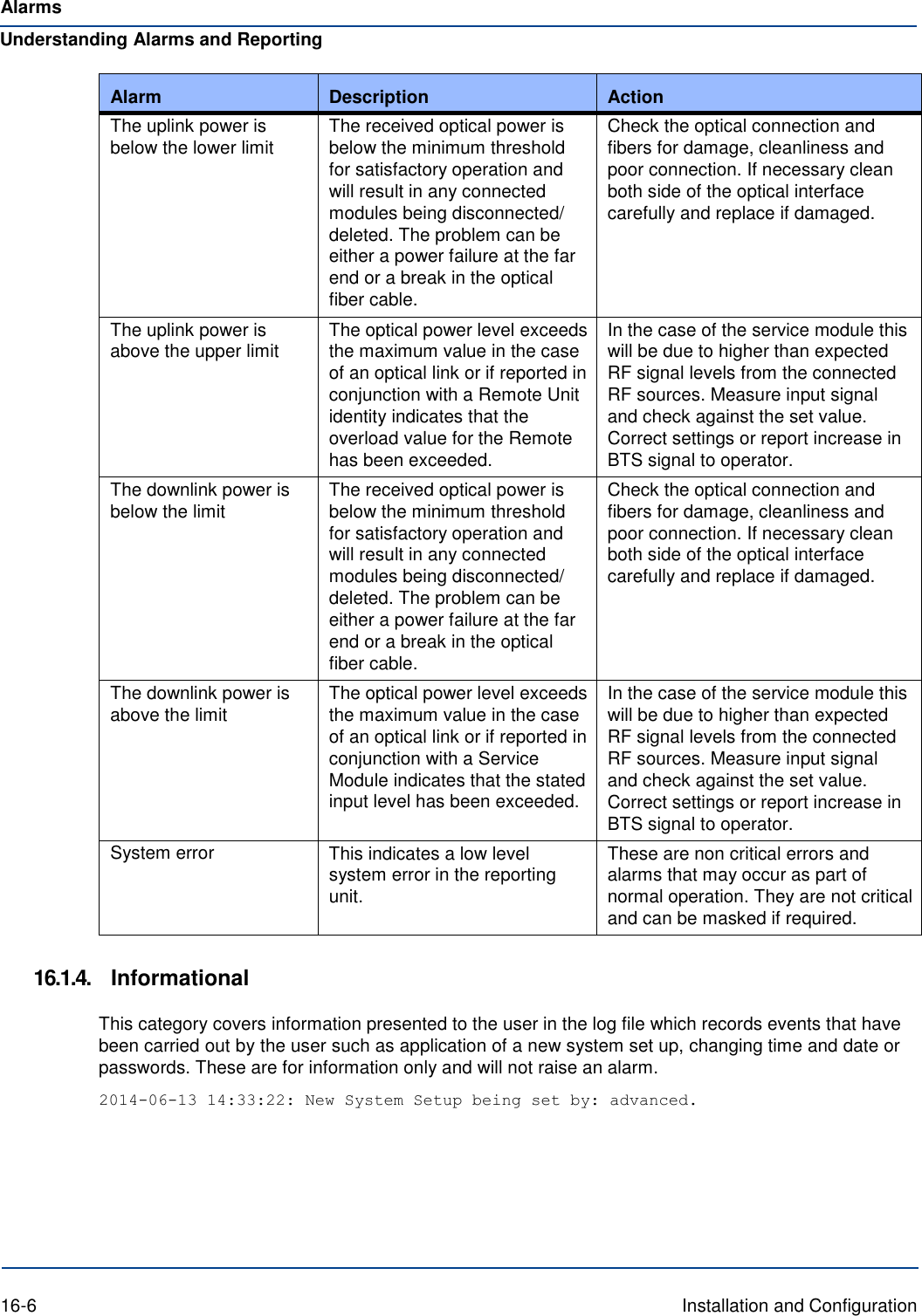
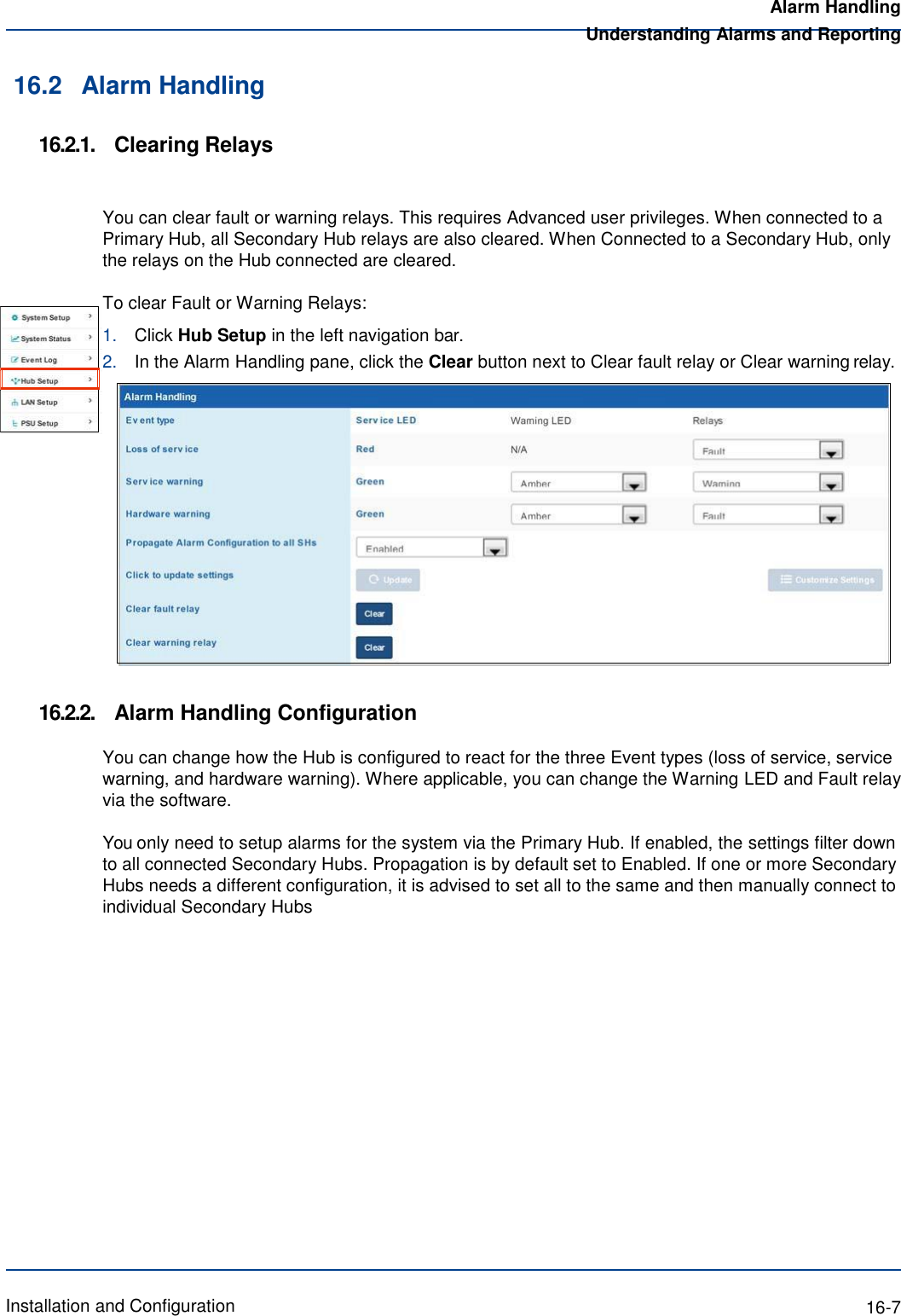
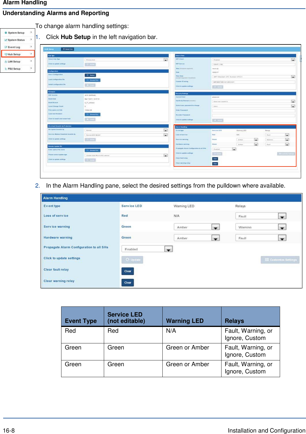
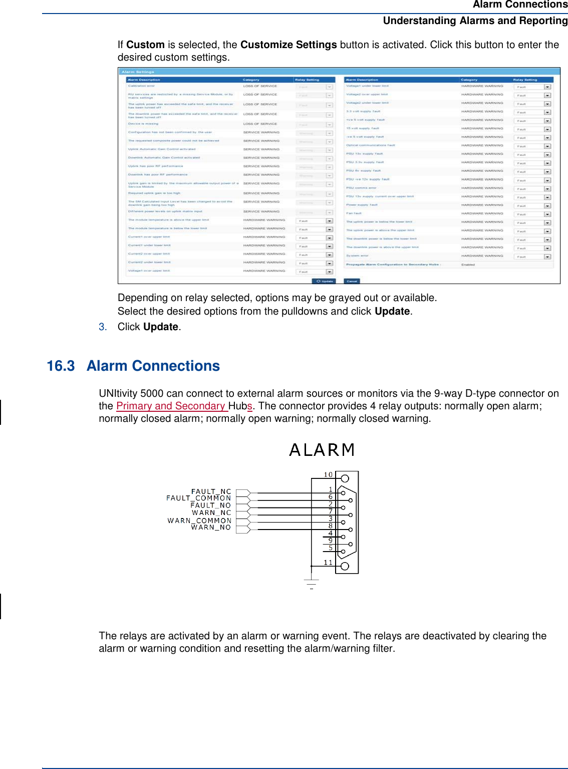
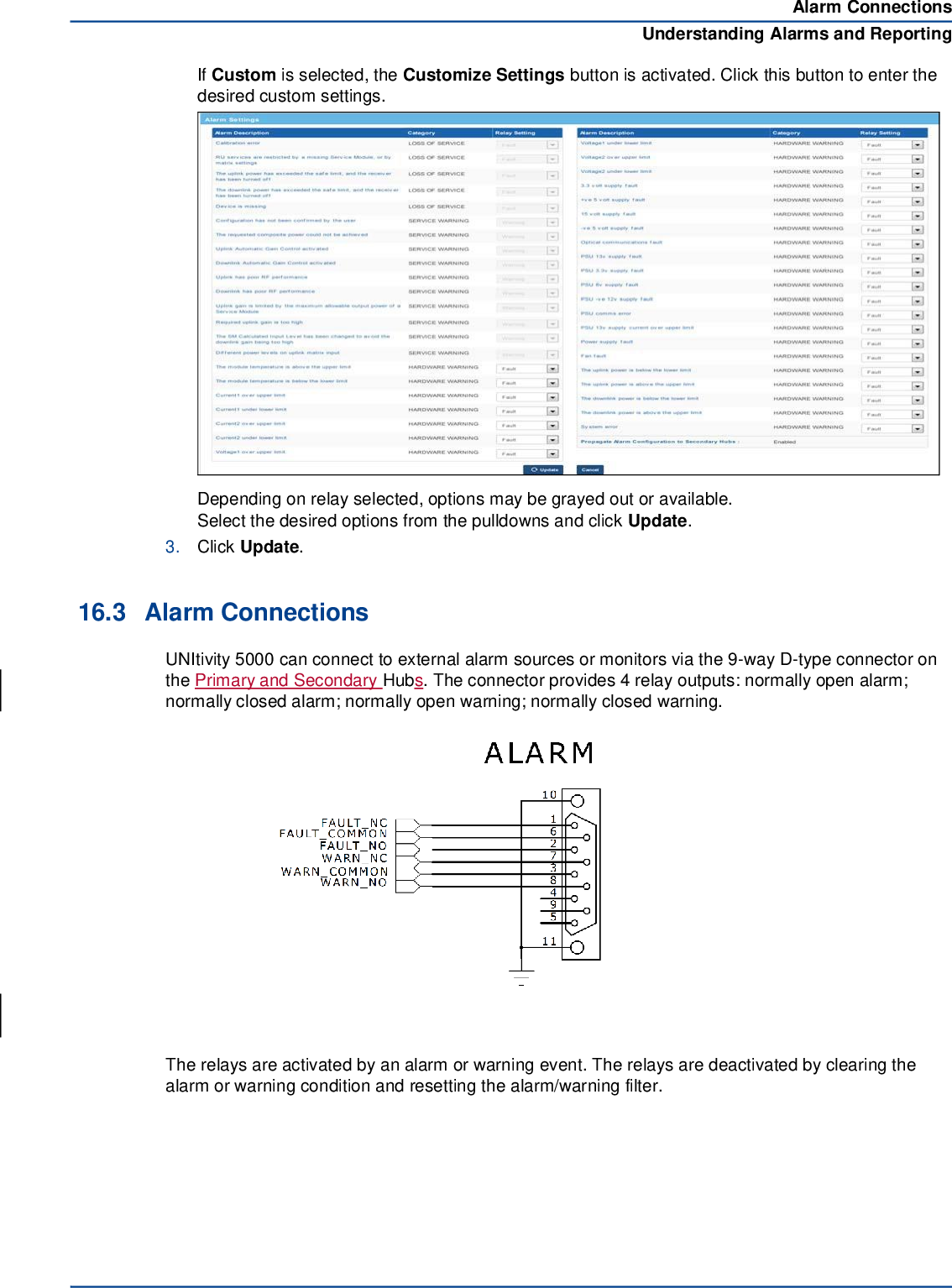
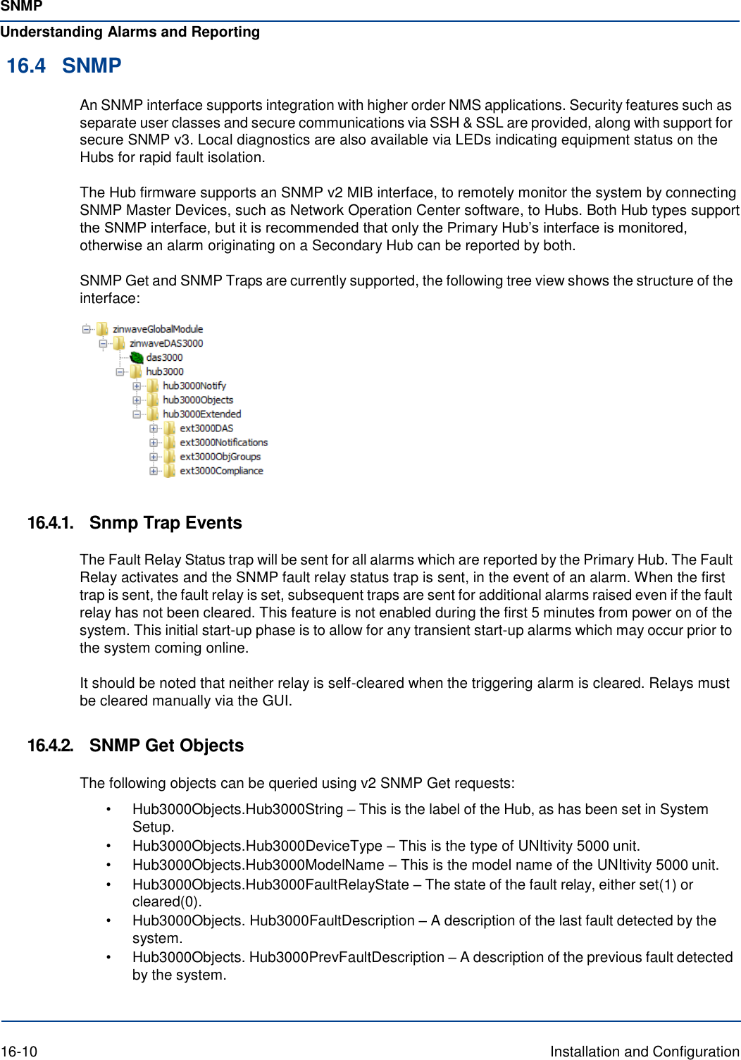
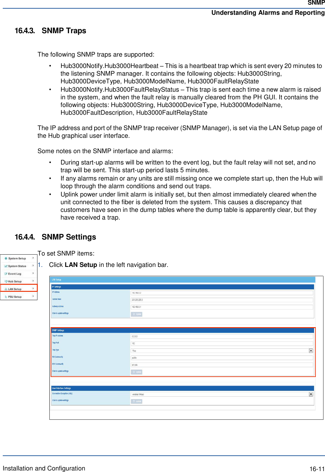
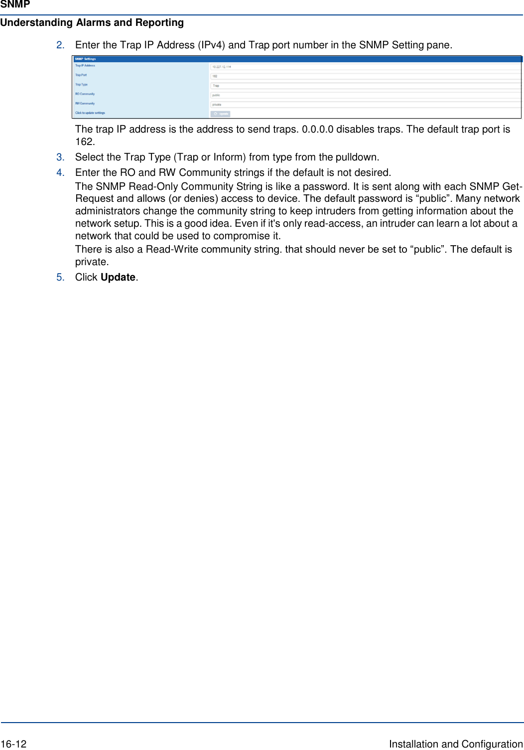
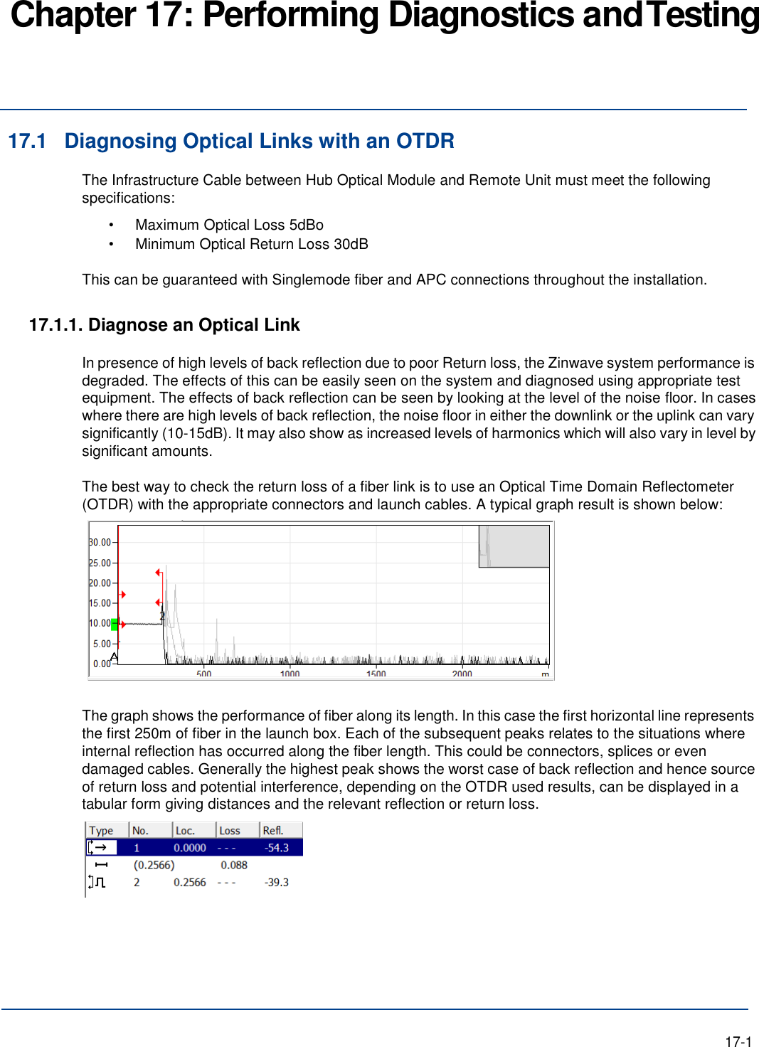
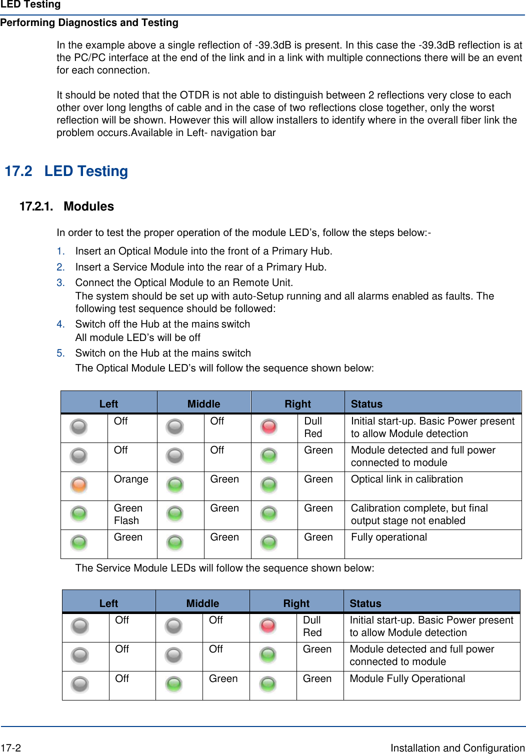
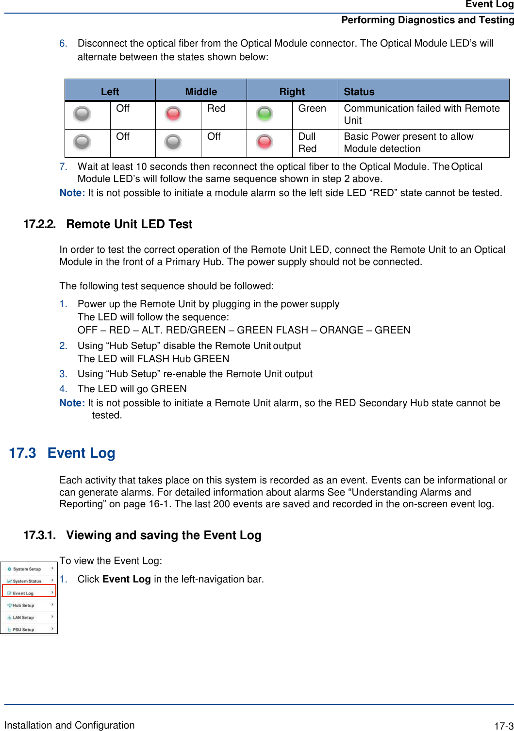
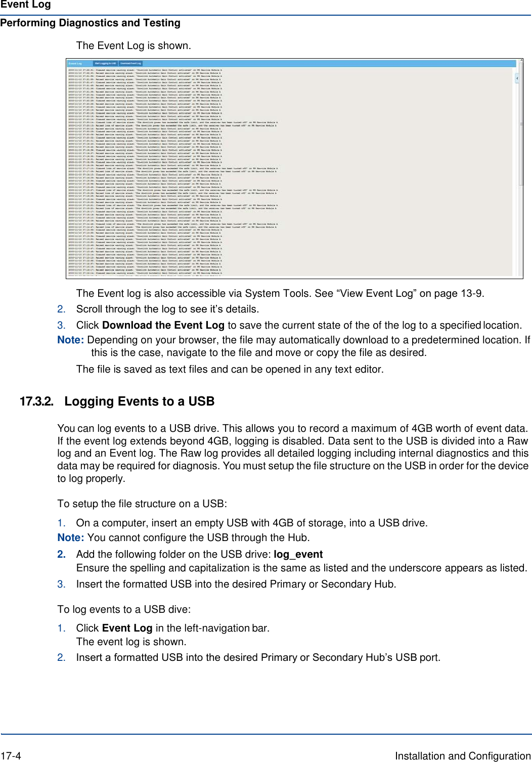
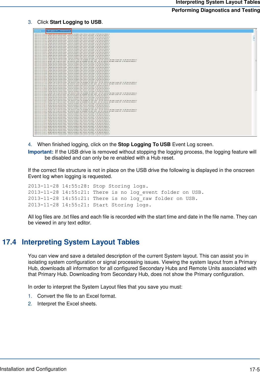
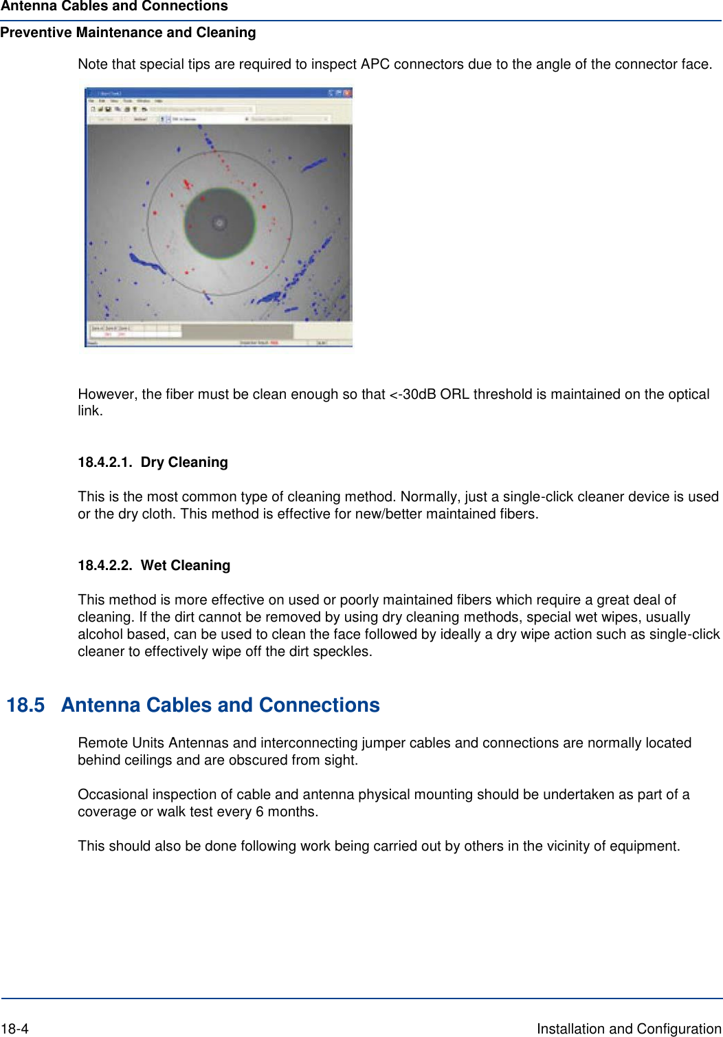
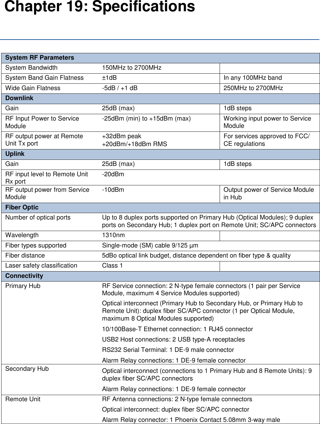
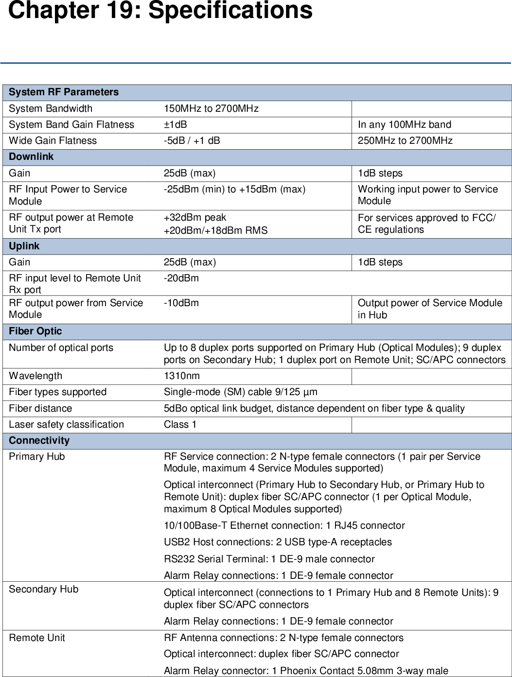
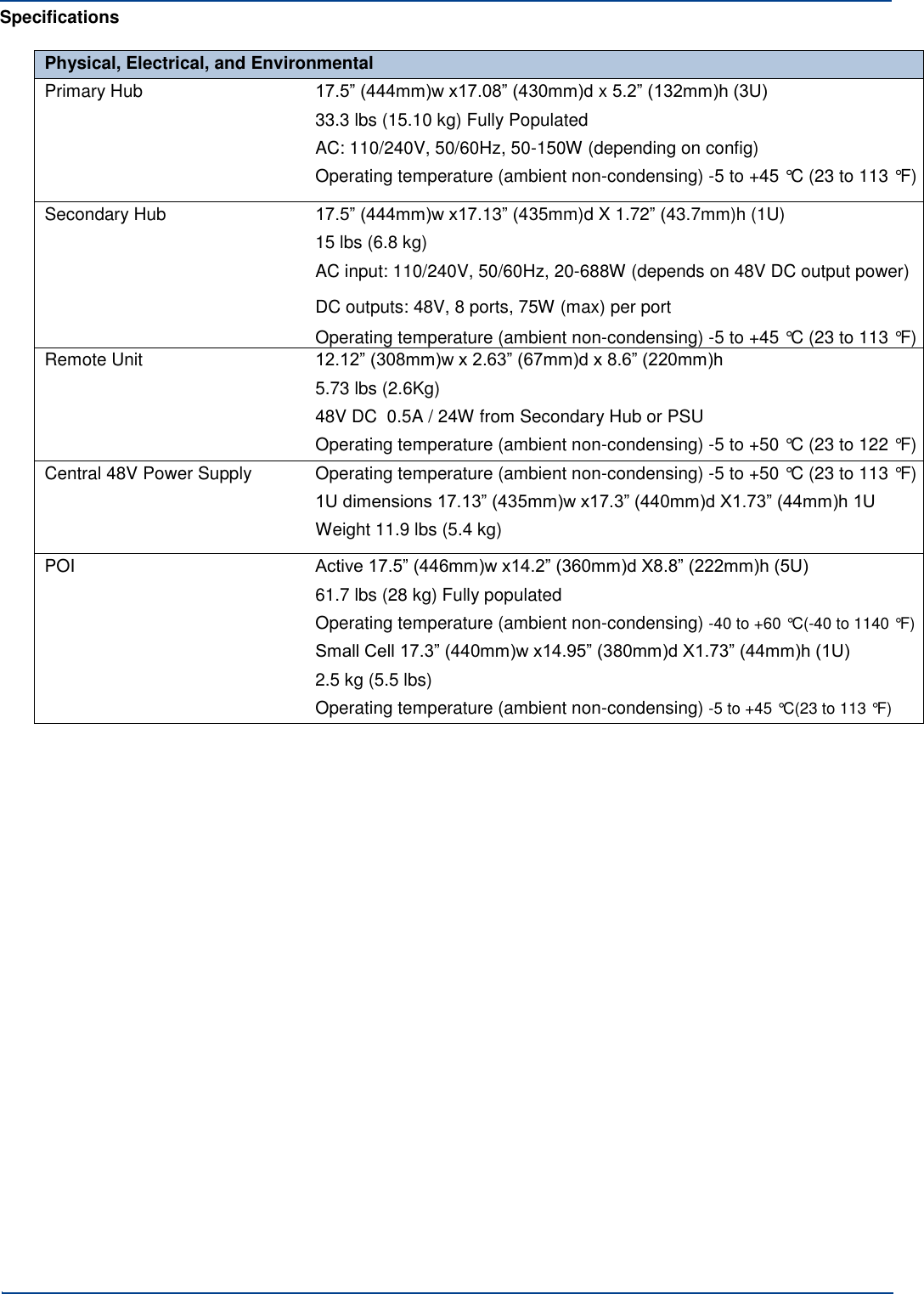
Users manual