softDSP SDU2040 DYNAMIC SIGNAL ANALYZER User Manual users manual 1
softDSP Co., Ltd. DYNAMIC SIGNAL ANALYZER users manual 1
UserManual.wiki
>
softDSP
>
SDU2040 User Manual
>
users manual 1
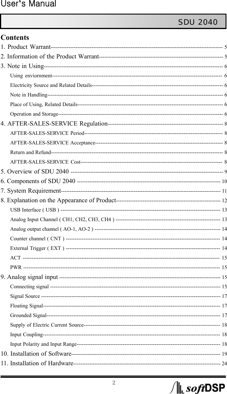
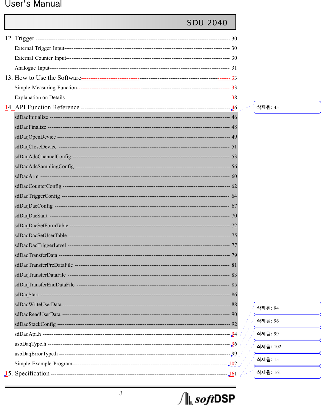
Contents
1.
users manual 1
2.
users manual 2
users manual 1
Navigation menu
Upload a User Manual
Namespaces
Wiki Guide
HTML
PDF
Info
Views
User Manual
Discussion / Help
Navigation