AM232 Manual Audiometer Operating Instructions 1243
2015-06-20
: 360 1243 1243 produccion
Open the PDF directly: View PDF ![]() .
.
Page Count: 24
AM 232™ Manual Audiometer
Operating
Instruction
Manual

Contents
Section 1 — Introduction
1.1 Description ...................................................................1
1.2 Unpacking and Inspection ............................................ 1
1.3 Connectors, Controls and Indicators............................ 2
1.3.1 The Front Panel Controls and Indicators (Fig. 1-1).... 3
1.3.2 Rear Panel Connectors and Indicators (Fig. 1-1)....... 3
1.3.3 Symbols ....................................................................3
1.4 Installation.....................................................................4
1.5 Pre-Test Procedure ...................................................... 4
1.5.1 Pre-Test Noise Recover Period ................................. 5
1.5.2 Elimination of Ambient Noise..................................... 5
Section 2 — Battery Option
2.1 Description ...................................................................6
2.2 NiCad Battery Operation .............................................. 6
2.3 Recharge NiCad Batteries ............................................ 7
2.4 To Replace NiCad Batteries ......................................... 8
2.5 Alkaline Battery Installation/Operation .......................... 9
Section 3 — Operation
3.1 Preliminary Check.......................................................10
3.2 Instructing the Subject................................................ 10
3.3 Placement of Earphones.............................................11
3.4 Response Handswitch................................................ 11
3.5 Audiogram Form.........................................................11
3.6 Routine Calibration Check .......................................... 12
3.7 Routine Test Administration........................................ 12
3.7.1 HL Control (F3) ........................................................12
3.7.2 Range Extension Push-Button (F2) ......................... 12
3.7.3 Tone Type Selector (F9) .......................................... 13
3.8 Typical Testing Session .............................................. 13
3.8.1 Pre-Test Review ......................................................13
3.8.2 Familiarization.......................................................... 13
3.8.3 Threshold Determination (Pure Tone) ...................... 14
3.8.4 Testing Procedure ...................................................14
Section 4 — Routine Maintenance
4.1 Calibration...................................................................15
4.2 Earphone Cords .........................................................15
4.3 Hum and Random Noise ............................................ 15
4.4 Distortion and Frequency Shift ................................... 15
4.5 Special Messages.......................................................16
4.5.1 CAL .........................................................................16
4.5.2 Exx ..........................................................................16
Service and Warranty Information
Service and Repair................................................................17
Recalibration .........................................................................17
Warranty ...............................................................................17
Rechargeable Battery Warranty ............................................ 17
Specifications ................................................................18
Bibliography ...................................................................20

Section 1 — Introduction
1.1 DESCRIPTION
The Welch Allyn AM 232 Manual Audiometer is a single-channel, pure
tone, air conduction, portable instrument designed to provide basic
audiometric capability for physicians’ offices, schools and industry. The
lightweight design allows easy transport to a variety of testing locations
and the built-in storage cavity and case provide enough room to contain
all instrument accessories. The clearly labeled front panel controls and
full frequency range make accurate, reliable testing a simple matter for
any user.
The Welch Allyn AM 232 Manual Audiometer is a precisely designed
and calibrated instrument. With proper care it will deliver accurate
sound-pressure levels for years to come. The Welch Allyn AM 232
Manual Audiometer should be recalibrated yearly (or sooner if a prob-
lem develops). See Section 4.
1.2 UNPACKING AND INSPECTION
Although your Welch Allyn AM 232 Manual Audiometer was carefully
tested, inspected and packed for shipping, it is good practice after re-
ceiving the instrument to immediately examine the outside of the con-
tainer for any signs of damage. Notify your distributor if any damage is
noted.
Carefully remove your Welch Allyn AM 232 Manual Audiometer from its
shipping container. If the instrument appears to have suffered mechani-
cal damage, notify the carrier immediately so that a proper claim can be
made. Be certain to save all packing materials so that the claim adjuster
can inspect it as well. As soon as the carrier has completed the inspec-
tion, notify your Welch Allyn representative.
If the instrument must be returned to the factory, repack it carefully (in
the original container if possible) and return it prepaid to the factory for
necessary adjustments.
Check that all accessories itemized in Table 1-1 are received in good
condition. If any accessories are missing, contact your Welch Allyn rep-
resentative immediately. See Specifications Section of this manual for
the catalog numbers of accessories and also for a listing of optional
accessories.
TABLE 1-1: Accessories Supplied
Test Headset Assembly (TDH39)
Audiogram Pad (1 Pad of 50)
Battery Pack Assembly (used with model #23210 and #23215 only)
AC Power Cord
1
1
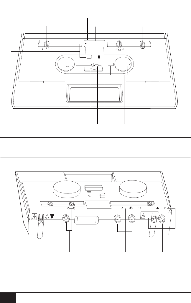
1.3 CONNECTORS, CONTROLS AND INDICATORS
FIGURE 1-1: Front and Rear Panel
12 VDC
200 MM
90
LO BAT
Front Panel
Rear Panel
F10
F1
F2
F5
F3
F8
F9
F4
F3 F6
F7
R3 R2 R1
2

1.3.1 The Front Panel Controls and Indicators (Figure 1-1)
F1 Power switch and indicator for ON and OFF
F2 Range extension push-button allows operator to increase the
stimulus intensity 10 dB above the standard maximum HL at
any frequency. When in use, a “+” appears on the LCD.
F3 HL control for setting stimulus intensity level. Level is indicated
on LCD.
F4 Present bar for stimulus presentation.
F5 Stimulus being presented via earphone. Presentation indicated
by illuminated green LED.
F6 Subject response indicator shows the operator when the test
subject has pressed the handswitch button by an illuminated
green LED (with optional handswitch only).
F7 Control for setting stimulus frequency. Frequency is indicated
in window adjacent to control.
F8 Routing switch for stimulus presentation to the earphone. Left
or right indicated by illustration of subject.
F9 Switch for setting the stimulus tone type.
FM = warble tone
= steady tone
= pulsed tone
F10 Low battery indicator to alert the operator of a limited oper-
ating time. Recharge or replace batteries (dependent on
whether NiCad or Alkaline batteries are used).
1.3.2 Rear Panel Connectors and Indicators (Figure 1-1)
R1 Power input jack (5-pin DIN Connector) with front panel illus-
tration showing its location and a rear panel label giving the
input power specifications.
R2 Earphone output jacks (standard phone jacks). Front panel
illustration shows left and right phone.
R3 Response handswitch input jack (standard phone jack) with
front panel illustration showing location.
1.3.3 Symbols
Attention, consult accompanying document for instructions or
warnings pertaining to these parts.
Entry by qualified service personnel only.
This symbol is located inside the storage compartment.
It denotes a Type B, Class II product per IEC 878 as refer-
enced in IEC 601 Standard.
3

1.4 INSTALLATION
Warning
The AM 232 Manual Audiometer is designed to be used with a hospital grade
outlet. Injury to personnel or damage to equipment can result when a three-
prong or two-prong adapter is connected between the AM 232 Manual Audio-
meter power plug and an AC outlet or extension cord. Additionally, the AM 232
Manual Audiometer is equipped with a specific power transformer which
should not be interchanged with any other transformer or supply.
The above symbol indicates the location of a service adjustment part and is
intended for service personnel use only. The AM 232 Manual Audiometer is
a specifically calibrated audiometer and the periodic service and adjustments
which the instrument may require should be done only by an authorized Welch
Allyn service technician.
Plug the power module into the appropriate jack (R1) on the back panel
of the instrument, then plug the other end into a line power (mains) outlet.
Plug the earphones into the earphone jacks (R3) on the rear panel. Note
the symbol along the top of the front panel which indicates which is
right and which is left. The right earphone is red, the left earphone
is blue. Turn the power switch to ON.
NOTE
For battery operation, please refer to Section 2.
1.5 PRE-TEST PROCEDURE
NOTE
The AM 232 Manual Audiometer is a versatile audiometer designed for use in
doctors’ offices, schools, industrial settings, the military, etc. This manual,
therefore employs the generic term “subject” to identify the person whose
hearing is being evaluated.
Although the AM 232 Manual Audiometer is simple enough to be oper-
ated by practically anyone, any program aimed at obtaining reliable re-
cords of hearing thresholds should be staffed and supervised by appro-
priately-trained individuals. Training courses leading to certification are
available for audiometric technicians in most urban areas.
Two prerequisites are of particular importance to the procurement of
reliable audiograms:
•Prior to testing, allow adequate time for the subject to recover
from the effects of previous exposure to high-level sound.
•Tests should be done in a quiet area.
4

1.5.1 Pre-Test Noise Recover Period
Exposure to high levels of sound (unmuffled lawn mowers, many power
tools,
loud music, gunfire) tends to create a temporary threshold shift
(TTS) which diminishes with time after exposure. Any subject tested
soon after such exposure may manifest a hearing loss that does not re-
flect his or her normal hearing threshold. It is, therefore, important that
the testing procedure prescribe some time interval — usually at least 16
hours — between the last exposure to high-level sound and the adminis-
tration of any hearing test.
1.5.2 Elimination of Ambient Noise
Excessive noise in the test environment such as that produced by con-
versation, typewriters, or other machines also reduces test validity be-
cause it tends to mask the test signals, particularly at the lower fre-
quencies where earphone cushions provide less effective attenuation.
An acoustically-tested room may be required if ambient noise at the
subject’s ears reaches an objectionable level—i.e., sufficient to cause
apparent hearing loss at the low frequencies. Also, Audiocups are avail-
able from Welch Allyn as an optional accessory. If the test subject is in
the same room as the audiometer, it is recommended that the subject
be seated about one meter (3 ft) away from the instrument.
Maximum permissible test environment sound-pressure levels are spe-
cified by American National Standard Criteria for Permissible Back-
ground Noise during Audiometric Testing, S3.1-1991. Table 1-2 shows
the maximum background levels that can be present inside the room
while a valid hearing test is being conducted. For more comprehensive
information about hearing testing and hearing conservation, refer to the
Bibliography.
TABLE 1-2: Permissible Noise Levels
Test Tone
Frequency (Hz) 125 250 500 750 1000 1500 2000 3000 4000 6000 8000
Test Room
Ears covered 34.0 22.5 19.5 21.5 26.5 26.5 28.0 33.5 34.5 38.0 43.5
maximum
permissible octave
band levels
Ears covered 29.0 17.5 14.5 16.5 21.5 21.5 23.0 28.5 29.5 33.0 38.5
maximum
permissible one-third
octave band levels
5

Section 2 — Battery Option
2.1 DESCRIPTION
This section describes the battery option of the AM 232 Manual Audio-
meter. It pertains only to those customers who purchased Models
#23210 or #23215 with the battery pack installed or to those who later
purchased the #72329 Battery Pack Assembly. In both cases, a re-
chargeable NiCad battery is included.
2.2 NiCad BATTERY OPERATION
The AM 232 Manual Audiometer battery option is supplied with an in-
stalled, rechargeable NiCad battery pack. It requires about 18 hours to
fully charge and will provide about 22 hours of continuous operation
when fully charged. The green LED on the pack itself will be lit when
charge is getting low so the operator will know when to recharge the
batteries. When LO BAT appears, the instrument will operate (continu-
ously) for about two more hours before it shuts down completely.
NOTE
In no instance will loss of battery power affect instrument calibration.
To save battery life, the AM 232 Manual Audiometer has a special
“sleep mode” in which the audiometer will shut down after five minutes
of no operation. The operator will know the instrument is “asleep” be-
cause the LCD will show three dash lines (---). To “wake up” the instru-
ment the operator only needs to press the present bar. There is no
danger of presenting a loud tone to the test subject when the instru-
ment “wakes up” because no tone is presented until the audiometer
is awake. In addition, the instrument automatically resets its output to
0 dB HL.
If the AM 232 Manual Audiometer is operated until the battery charge
has dropped below an acceptable voltage level, the instrument will not
function at all. The display will be blank except for the LO BAT indica-
tion, and the controls will not function. To restore operation, the bat-
teries must be recharged for some period of time up to 18 hours (full
charge), or line power (mains) may be used. If the audiometer is oper-
ated using line power (mains) with the rechargeable batteries in place,
some battery charging will occur.
6
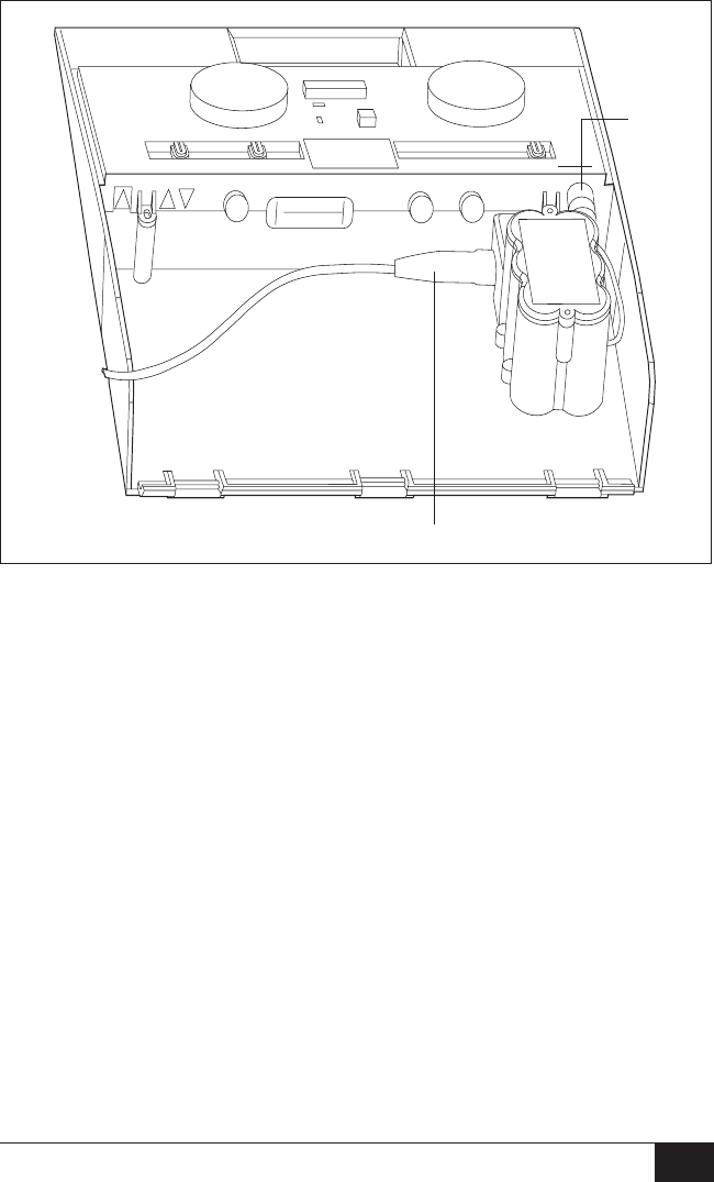
2.3 RECHARGE NiCad BATTERIES
FIGURE 2-1: NiCad Battery Recharge
Refer to Figure 2-1 when recharging NiCad batteries and proceed as
follows:
a. Be certain that the battery pack power cord is connected to the
power cord receptacle on the back panel of the audiometer (A).
b. Connect the instrument power cord to the receptacle on the
lower edge of the battery pack (B).
c. Plug the power cord into a wall outlet.
CAUTION
Although no damage to the rechargeable NiCad batteries will occur if the pack
is left charging for more than the 18 hours required for a full charge, the batteries
should not be left charging for extended periods (i.e., several days) because
the useful life of the rechargeable NiCad pack will be shortened. Welch Allyn
recommends unplugging the battery pack power input cord from the back of
the audiometer and plugging the main line power cord into the jack if main line
power is to be used most of the time.
B
A
7
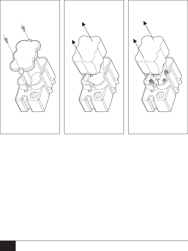
2.4 TO REPLACE NiCad BATTERIES
Please refer to Figures 2-2, 2-3, 2-4 and proceed as follows:
a. Unplug the AM 232 Manual Audiometer from the line power (mains).
b. Remove the two screws on the battery pack cover and lift off the
cover.
c. Pull the NiCad battery out of the pack. The battery is actually a set
of six batteries wrapped in plastic, but they will be removed as a
single unit.
d. Carefully disconnect the lead wires of the NiCad battery from the
battery compartment by removing the small connector. Remove
NiCad pack.
e. Attach the lead wire connector on the new NiCad battery to the
mating connector within the battery pack base. Place the new
NiCad into the battery pack.
f. Replace the battery pack cover. There is only one way that the
cover can be replaced and the screws tightened. Note that the
screw housing is longer on one end. Orient the top cover so that
it will sit flat on the top of the battery compartments and replace
screws.
FIGURE 2-2: FIGURE 2-3: FIGURE 2-4:
Battery Cover NiCad Battery Pack Internal View of
Removal Removal Battery Compartment
8

2.5 ALKALINE BATTERY INSTALLATION/OPERATION
For longer continuous battery operation, such as periods when recharg-
ing on a regular basis is not possible, the rechargeable batteries can be
replaced with six size C alkaline batteries. These batteries will provide
about 45 hours of continuous operation.
The low voltage indicator works the same way for the alkaline batteries
as it does for the NiCad batteries. The words LO BAT will appear on
the LCD when about six hours of continuous battery operation remain.
In addition, the “sleep mode” also works with the alkaline batteries to
prolong their useful life.
To install the alkaline batteries, refer to Figures 2-2, 2-3, 2-4, and
proceed as follows:
a. Unplug the AM 232 Manual Audiometer from the line power (mains).
b. Remove the two screws on the battery pack cover and lift off the
cover.
c. Pull the NiCad battery out of the pack. The battery is actually a set
of six batteries wrapped in plastic, but they will be removed as a
single unit.
d. Carefully disconnect the lead wires of the NiCad battery from the
battery compartment by removing the small connector. Remove
NiCad pack.
e. There are six spring mounts on the top and bottom of the battery
compartment to hold the alkaline batteries. The label on the bot-
tom surface of the compartment indicates the correct position for
each battery. Place each one of the six batteries into the pack
matching the polarity (+ or -) as shown on the label.
f. Replace the battery pack cover. Make certain that the cover is po-
sitioned with the spring mounts touching the batteries. There is
only one way that the cover can be replaced and the screws tight-
ened. Note that the screw housing is longer on one end. Orient
the top so that it will sit flat on top of the battery compartment and
replace screws.
NOTE
If the alkaline batteries are not going to be used on a regular basis, they
should NOT be stored in the audiometer. They should be removed from the
battery pack and stored in a cool, dry place.
9

Section 3 — Operation
Throughout this section there are references to front panel (F) and rear
panel (R) connectors, controls and indicators. Please refer to Section 1.3
and Figure 1-1 for specific descriptions and locations.
3.1 PRELIMINARY CHECK
Prior to testing, ensure that the power cord and earphone cords are
plugged in (R1 and R2 respectively). Turn the audiometer on, select the
desired tone type (F9—pulsed, steady or FM) and make whatever nota-
tions your procedure requires on the audiogram form.
CAUTION
Always handle earphones with care. Neither drop them nor permit them to be
squeezed together. Severe mechanical shock may change their operating
characteristics and require their replacement.
IMPORTANT
Always clean and maintain your earphone cushions, for hygiene purposes.
Check periodically for cracking or signs of wear. Cleanse cushions daily or
after each use (depending upon population being tested). Use a solution of
diluted alcohol or mild soap and water, taking care not to get any of the
cleaning solution into the earphone speaker. Use earphones only when
completely dry. Insert the earphone cords between the earphone cushions
during storage to prevent damage from mechanical shock.
3.2 INSTRUCTING THE SUBJECT
The operator should put the subject as much at ease as possible
before the test begins. In addition, he/she should try to make the
subject understand how the test is to be conducted and what the
subject will hear. For the sake of uniformity, an unvarying explanation
is advisable—something close to the following:
“I am going to place these earphones over your ears. You
will hear a variety of tones—some high, some low, some
loud, some very soft. Whenever you hear, or think you hear
one of those sounds, raise your hand. Lower your hand
when you no longer hear the sound.
“Remember that though some of the tones will be easy to
hear, others will be very faint. Therefore, you should listen
very carefully and raise your hand whenever you think you
hear the tone.”
Modify the instructions accordingly if the optional response
handswitch is to be used.
10

3.3 PLACEMENT OF EARPHONES
The most important thing to remember is that a good seal is required
between the earphone cushion and the subject’s head and ear. To
increase the likelihood of a good seal:
a. Eliminate all obstruction between earphone and subject (hair,
eyeglasses, earrings, hearing aids, etc.).
b. Adjust the headband so that it rests solidly on the crown of the
subject’s head and exerts firm pressure on both ears.
c. Center earphones carefully over both ears—earphone with red
connector on right ear. Take care to eliminate any visible gaps
between earphone cushions and portions of the subject’s head
and the ear on which the cushion rests.
3.4 RESPONSE HANDSWITCH
If the optional Response Handswitch is to be used, insure that the
plugs and jacks are properly connected. The subject response indica-
tor on the front panel will be illuminated when the subject presses the
response button.
3.5 AUDIOGRAM FORM
The AM 232 Audiogram Form (see Figure 3-1) consists of three distinct
parts:
• Space for entering information about the person to be tested.
• A convenient chart for manually plotting test data.
• Space for entering comments about the subject or the test.
FIGURE 3-1: Audiogram Form 11
AM 232 AUDIOGRAM
Name
Age Sex Date Time
Job Description
Audiometer Model No.
Serial No.
Examiner
Signature
COMMENTS
Ear
Left
Right
Response No
Response Phone
Blue
Red
250 500 750 1000 1500 2000 3000 4000 6000 8000
-10
0
10
20
30
40
50
60
70
80
90
100
110
120
TONE FREQUENCY (Hz)
HEARING LEVEL IN DECIBELS
ISO 389-1985 ANSI S3.6-1989
SYMBOLS
232002
Printed in U.S.A.
Customer Reorder No. 52300

3.6 ROUTINE CALIBRATION CHECK
The microprocessor-controlled circuitry and quality construction of the
AM 232 Manual Audiometer will provide long and reliable service. It is
good practice, however, to make and file, at the start of each month’s
testing, the audiogram of a single subject or of a small group of subjects
who are likely to be routinely available for this purpose. Where physical
arrangements permit, the operator can serve as a subject.
This procedure should commence when the audiometer is installed,
and be performed each month thereafter. If the AM 232 Manual Audio-
meter is to be used to monitor employee thresholds as part of an indus-
trial Hearing Conservation Program, this “biological listening check”
must be done at the beginning of each day the audiometer is to be
used (per CFR 1910.95 Occupational Noise Exposure, March 8, 1983).
Since individual thresholds can shift up or down as much as 5 dB from
one day to the next, variation within this range may be considered ac-
ceptable. Variations that exceed this range, however, are likely to reveal
problems that require attention. The routine maintenance checks de-
scribed in Section 4 may suggest the source and solution to the prob-
lem. If they do not, the instrument should receive technical service by a
certified technician before further use.
3.7 ROUTINE TEST ADMINISTRATION
3.7.1 HL Control (F3)
The HL control will increase or decrease the presented intensity in
5 dB HL steps with the currently available intensity appearing on the
LCD. Rotating the control knob clockwise increases the intensity. Ro-
tating the control knob counter-clockwise decreases intensity. When
the maximum or minimum available intensity is reached for any fre-
quency, the display will flash to alert the operator he/she cannot ex-
ceed the available range.
3.7.2 Range Extension Push-Button (F2)
This control allows the operator to present tones of up to 10 dB above
the standard maximum HL at any frequency. It will only function when
the intensity is set within 10 dB below the maximum standard intensity
at any frequency. This feature requires an extra step to access or use
the highest available intensities, requiring the operator to make note of
those individuals requiring testing at these levels. It also prevents acci-
dental presentation of the highest intensities to normal subjects, and it
alerts the operator to present the stimulus for only brief periods of time.
12

To enable the range extension feature, simply push the button labeled
+10 dB. Note the appearance of the “+” sign on the LCD. To disable
the feature, either push the button a second time, reduce the intensity
(with the HL control knob) to 20 dB below the standard maximum HL,
or change any other parameter (frequency knob, routing switch).
3.7.3 Tone Type Selector (F9)
This control allows the operator to choose the type of tone presented
to the test subject. It can be set on steady, pulsed (2.5 pulses per
second) or FM (warble tone). Pulsed tones and warble tones are often
used with difficult-to-test subjects, such as children and hard-of-hearing
individuals, because they hold the subject’s attention better than the
steady tone.
3.8 TYPICAL TESTING SESSION
3.8.1 Pre-Test Review
a. Turn the instrument on.
b. Check that the earphones are operating properly.
c. Seat subject comfortably in the test area.
d. Explain the test procedure.
e. Assist subject with the earphones.
f. Select the desired tone type.
g. Make appropriate entry on the subject’s audiogram.
3.8.2 Familiarization
a. Set the routing selector to route the test tone to the selected ear.
Demonstrate the 1000 Hz tone at a 40 dB level. Duration of tone
should be between one and two seconds.
b. Set HL control to -10 dB.
c. Practice: Beginning with the tone continuously on (Present Bar held
down) gradually increase the intensity by turning the HL control
until a response occurs. Switch the tone off for at least two seconds
and present the tone again at the same level. If there is a second
positive response, proceed to threshold measurement. If a second
response does not occur, repeat this step. Practice is preliminary
to threshold measurement determination and is to be completed at
each new frequency setting.
13

3.8.3 Threshold Determination (Pure Tone)
a. The level of the first presentation shall be 10 dB below the level at
which the subject responded during the familiarization procedure.
Present the tone for a period of one or two seconds. Time between
tones can be varied, but not shorter than the duration of the test
tone itself. After each failure to respond to a signal, the level is in-
creased by 5 dB until the first response occurs. After the response,
the intensity is decreased 10 dB and another ascending series
is begun.
NOTE
Descend in 10 dB steps and ascend in 5 dB steps.
b. The threshold is considered to be the minimum dial setting at
which a response has occurred two out of three times. Record
this setting on the audiogram form.
3.8.4 Testing Procedure
a. Repeat 3.8.2 and 3.8.3 for each tone-setting in the following order:
1000, 2000, 3000, 4000, 6000 and 8000 Hz. Retest 1000 followed
by 500 and 250. If there is a difference of 20 dB or more between
two successive octaves, test the inter-octave responses, i.e. 750,
1500, 3000 Hz. Record this information on the audiogram form.
b. Repeat process (3.8.2, 3.8.3, 3.8.4) for the other ear.
14

Section 4 — Routine Maintenance
4.1 CALIBRATION
The biological listening check, or routine check, should be performed at
least monthly (see section 3.6 for description and explanation).
The following checks should be made at periodic intervals, even if routine
calibration checks do not reveal any problems. These procedures presup-
pose normal hearing on the part of the person doing the checking.
4.2 EARPHONE CORDS
With extended use, earphone cords tend to fray internally at the junc-
tions of both earphone and audiometer connectors. This fraying will
ultimately either decrease the signal level in the associated earphone
or cause signals to be intermittent as the cord is flexed.
To check for either condition, set the audiometer frequency control (F7)
to 1000 or 2000 Hz, set HL control (F3) at a comfortable audible level,
press the Present Bar (F4) and flex earphone cord next to plug at both
ends, listening for intermittent signal, abrupt changes in signal level, or
a scratchy sound superimposed over the signal that coincides with the
flexing of the cord. The presence of any of these three conditions signifies
that the cord should be replaced.
Repeat the test for the other earphone.
4.3 HUM AND RANDOM NOISE
This test can be made during the check for attenuator noise. With the
instrument set on 1000 Hz, move the HL control (F3) from 0 to 60 dB
and listen for low-frequency hum (60 to 120 Hz) and random noise (hiss
or low rushing sound) at all attenuator levels. Some audible random noise
at levels above 60 dB is permissible. Below 60 dB, however, only the
signal should be audible. Any of these noises can be confused with the
signal by naive subjects and affect the accuracy of the audiogram. Sched-
ule the audiometer for immediate service if any of the three is detected.
4.4 DISTORTION AND FREQUENCY SHIFT
This check can be best made by listening to the output of the AM 232
Manual Audiometer through the earphones while presenting all 11 fre-
quencies at a loud, but not uncomfortable, level (70 to 80 dB HL for
normal ears).
Listen for rattling, rasping or distortion in the tones presented. Listen also
to ascertain that signal frequencies change plausibly when the frequency
selector (F7) is moved to a new position. If distortion is heard in one
earphone but not in the other, the chances are high that the earphones
are at fault and should be replaced. In any case, the audiometer should
be scheduled for immediate maintenance.
15

4.5 SPECIAL MESSAGES
The AM 232 Manual Audiometer is a microprocessor-controlled instru-
ment which performs a self-check each time the instrument is turned
on (the self-check does not occur when instrument operation resumes
from sleep mode). Certain messages will be displayed to the operator
on the front panel LCD if any error in the instrument operation is de-
tected. These messages are described below.
4.5.1 CAL
When a transducer or frequency is selected which has a calibration
error (e.g., right earphone at 2000 Hz), the word “CAL” will be display-
ed to the operator. The audiometer will not function at this frequency
with this transducer, so that no invalid results can be recorded. The word
“CAL” will be displayed as long as the “problem” transducer and fre-
quency are selected. If the calibration error is an isolated situation,
changing either the frequency or the transducer (e.g., left earphone at
3000 Hz) will restore normal instrument function.
As in the case with any instrument malfunction, a certified service tech-
nician should be contacted immediately. Remember to make note of
the combination of transducer and frequency which resulted in the
“CAL” message.
4.5.2 Exx
When an error code consisting of an “E” and a two-digit number
(xx = number) appears on the audiometer’s display, a system error has
been detected. The AM 232 Manual Audiometer will enter a “lock-out”
mode which will not permit the instrument to operate. The specific error
code will remain on the display for several seconds, then the instrument
will shut itself down completely. Should an Exx appear on the LCD, take
the following steps:
a. Power down, power up again. This could be only a temporary
failure and may never appear again. However, should the Exx
message appear again, proceed to steps b. and c.
b. Write down the numbers that appear on the display.
c. Contact your certified service representative and give them the
specific numbers you have recorded.
16

Service and Warranty Information
SERVICE AND REPAIR
Repair must be performed by authorized personnel. Failure to do so
invalidates the AM 232 Manual Audiometer warranty.
For customers in the United States or Canada, please contact Welch
Allyn for information on where to return your AM 232 Manual Audio-
meter for service.
Technical Service Department Technical Service Department
Welch Allyn, Inc. Welch Allyn Canada Limited
4341 State Street Road 160 Matheson Boulevard, East
Skaneateles Falls, NY 13153-0220 Mississauga, Ontario, Canada L4Z 1V4
Tel.: 1-800-535-6663 Tel.: 1-800-561-8797
(In U.S.A. only) (in Canada only)
RECALIBRATION
Welch Allyn recommends that the AM 232 Manual Audiometer be recal-
ibrated annually. Arrangements may be made by returning the instrument
registration card or by contacting Welch Allyn’s Technical Service De-
partment (as listed above). A moderate fee is charged for recalibration.
WARRANTY
NOTE
Return of the instrument registration card is required for proof of purchase and
warranty validation.
Welch Allyn, Inc. warrants the AM 232 Manual Audiometer to be free of original
defects in material and workmanship and to perform in accordance with manu-
facturer’s specifications for a period of one year from the date of purchase. If
this instrument or any component thereof is found to be defective or at vari-
ance from the manufacturer’s specifications during the warranty period, Welch
Allyn will repair, replace or recalibrate the instrument or component(s) at no
cost to the purchaser.
This warranty only applies to instruments purchased new from Welch Allyn or
its authorized distributors or representatives. The purchaser must return the in-
strument directly to Welch Allyn or an authorized distributor or representative
and bear the costs of shipping.
This warranty does not cover breakage or failure due to tampering, misuse,
neglect, accidents, modification or shipping and is void if the instrument is not
used in accordance with manufacturer’s recommendations or if repaired or
serviced by other than Welch Allyn or a Welch Allyn authorized representative.
No other express or implied warranty is given.
RECHARGEABLE BATTERY WARRANTY
Welch Allyn nickel-cadmium batteries are guaranteed by Welch Allyn for two
years from date of manufacture (when used in Welch Allyn instruments only).
Defective batteries will be replaced on a pro rata basis should failure occur
prior to expiration date on battery. 17

Specifications
Standards
The AM 232 meets ANSI S3.6 and IEC 645 Type 4 Audiometer Standards,
and IEC 601-1, CSA C22.2 No. 601-1, and UL 544 electrical standards.
Frequency Range
Discrete Frequencies:
125, 250, 500, 750, 1000, 1500, 2000, 3000, 4000, 6000, 8000 Hz
Accuracy: ±3%
Total Harmonic Distortion: <2%
Intensity
Ranges:
125 Hz, _10 to 50 dB HL
500 to 6000 Hz, _10 to 90 dB HL
250 and 8000 Hz, _10 to 70 dB HL
(increments of 5 dB steps)
NOTE
A “+10” dB switch extends maximum at all frequencies by 10 dB.
Accuracy:
125 to 4000 Hz, ±3 dB
6000 to 8000 Hz, ±5 dB
Signal to Noise Ratio: >70 dB
Tone Type
Rise/Fall Time: 20 to 50 msec
Continuous: Steady when present bar depressed
Pulse: 2.5 pulse/Sec
FM: 5 Hz, ±5%
Headset
Telephonics TDH39 Earphones with MX41AR Cushions
(60 ohm impedance)
Power
Line Voltage: 100 to 120 V or 200 to 250 V (±10%)
Range: 50 to 60 Hz (±5%)
Consumption: 9 Watts
Battery
Types: Rechargeable (NiCad) or Non-Rechargeable (Alkaline)
Range: 7.0 V to 9.0 V
Capacity:
NiCad—22 hours continuous operations
Alkaline—45 hours continuous operations
18

Environmental
Temperature:
Operating, 60° F to 105° F (15° C to 40° C)
Storage, Powerline _40° F to 140° F (_40° C to 60° C)
Storage, Battery _40° F to 105° F (_40° C to 40° C)
Humidity: 5% to 90%
Warm-up Time: 10 minutes for instruments stored at room temperature
Mechanical
Dimensions: 13.25" W x 14" D x 3.75" H
(33.66 cm x 35.56 cm x 9.53 cm)
Weight: 5.6 lb (2.53 kg) net
8 lb (3.64 kg) shipping
10 lb (4.55 kg) shipping with battery included
Accessories
Catalog
Numbers Catalog Listings
23200 AM 232 Manual Audiometer, AC Power (USA)
23205 AM 232 Manual Audiometer, AC Power (Export,
specify country and voltage)
23210 AM 232 Manual Audiometer, AC Power and Battery (USA)
23215 AM 232 Manual Audiometer, AC Power and Battery (Export,
specify country and voltage)
Supplied Accessories
23223 Test Headset (TDH39)
52300 Audiogram Forms (1 pad of 50)
232001 Instruction Manual
Optional Accessories
23220 Response Handswitch
23221 Patch Cord, 2 Conductor
23222 Audiocups
72320 Replacement NiCad Battery Only
72329 Battery Pack Assembly
Includes NiCad batteries. May also be used with six (6),
Size C Alkaline batteries (not included)
19

Bibliography
American National Standard Specifications for Audiometers
(ANSI S3.6—1989)
Criteria for Permissible Ambient Noise During Audiometric Testing
(ANSI S3.1—1977)
Methods for Manual Pure-Tone Threshold Audiometry
(ANSI S3.21—1978)
Michael P.L., and Bienvenue, G.R., “Noise Attenuation Characteristics
of Supra-Aural Audiometric Headsets Using the Models MX41/AR
and 51 Earphone Cushions,” J. Acoust. Soc. Am., 70(5), Nov. 1981,
1235-1238
Newby, H.A., Audiology (4th ed.), New Jersey: Prentice-Hall Inc. (1979)
U.S. Department of Labor, Occupational Noise Exposure, CFR 1910.95,
March 8, 1983
20

Printed in U.S.A. 1717-0101 Rev. 3
Welch Allyn, Inc.
4341 State Street Road
P.O. Box 220,
Skaneateles Falls, N.Y.
13153-0220 U.S.A.
Tel.: 800-535-6663
(in U.S.A. only) or
315-685-4560
Fax.: 315-685-3361
