3Com 3.01.01 8800ConfigGd User Manual To The 5049cd2b 4349 4b23 98d3 Cec81535b62b
User Manual: 3Com 3.01.01 to the manual
Open the PDF directly: View PDF ![]() .
.
Page Count: 356 [warning: Documents this large are best viewed by clicking the View PDF Link!]
- About This Guide
- System Access
- Port Configuration
- VLAN Configuration
- Network Protocol Operation
- IP Routing Protocol Operation
- Multicast Protocol
- QoS/ACL Operation
- ACL Overview
- Configuring ACLs
- Displaying and Debugging ACL Configurations
- ACL Configuration Example
- QoS Configuration
- Configuration Examples
- Traffic Policing Configuration Example
- Traffic Shaping Configuration Example
- Port Mirroring Configuration Example
- Traffic Priority Configuration Example
- Traffic Redirection Configuration Example
- Queue Scheduling Configuration Example
- WRED Parameters Configuration Example
- Traffic Statistics Configuration Example
- Configuring Logon User ACL Control
- STP Operation
- STP Overview
- Configuring STP
- MSTP Overview
- Configuring MSTP
- Configuring the MST Region for a Switch
- Specifying the Switch as Primary or Secondary Root Switch
- Configuring the MSTP Operating Mode
- Configuring the Bridge Priority for a Switch
- Configuring the Max Hops in an MST Region
- Configuring the Switching Network Diameter
- Configuring the Time Parameters of a Switch
- Configuring the Max Transmission Speed on a Port
- Configuring a Port as an Edge Port
- Configuring the Path Cost of a Port
- Configuring the Priority of a Port
- Configuring the Port Connection with the Point-to-Point Link
- Configuring the mCheck Variable of a Port
- Configuring the Switch Security Function
- Enabling MSTP on the Device
- Enabling or Disabling MSTP on a Port
- Displaying and Debugging MSTP
- AAA and RADIUS Operation
- Reliability
- VRRP Overview
- Configuring VRRP
- Enable Pinging the Virtual IP Address
- Setting Correspondence Between Virtual IP and MAC Addresses
- Adding and Deleting a Virtual IP Address
- Configuring the Priority of Switches
- Configuring Preemption and Delay for a Switch
- Configuring Authentication Type and Authentication Key
- Configuring the VRRP Timer
- Configuring a Switch to Track an Interface
- Displaying and Debugging VRRP
- Troubleshooting VRRP
- System Management

http://www.3com.com/
Switch 8800
Configuration Guide
Version 3.01.01
Published February 2005
Part No.10014298
3Com Corporation
350 Campus Drive
Marlborough, MA
01752-3064
Copyright © 2005, 3Com Corporation. All rights reserved. No part of this documentation may be reproduced
in any form or by any means or used to make any derivative work (such as translation, transformation, or
adaptation) without written permission from 3Com Corporation.
3Com Corporation reserves the right to revise this documentation and to make changes in content from time
to time without obligation on the part of 3Com Corporation to provide notification of such revision or change.
3Com Corporation provides this documentation without warranty, term, or condition of any kind, either
implied or expressed, including, but not limited to, the implied warranties, terms or conditions of
merchantability, satisfactory quality, and fitness for a particular purpose. 3Com may make improvements or
changes in the product(s) and/or the program(s) described in this documentation at any time.
If there is any software on removable media described in this documentation, it is furnished under a license
agreement included with the product as a separate document, in the hard copy documentation, or on the
removable media in a directory file named LICENSE.TXT or !LICENSE.TXT. If you are unable to locate a copy,
please contact 3Com and a copy will be provided to you.
UNITED STATES GOVERNMENT LEGEND
If you are a United States government agency, then this documentation and the software described herein
are provided to you subject to the following:
All technical data and computer software are commercial in nature and developed solely at private expense.
Software is delivered as “Commercial Computer Software” as defined in DFARS 252.227-7014 (June 1995)
or as a “commercial item” as defined in FAR 2.101(a) and as such is provided with only such rights as are
provided in 3Com’s standard commercial license for the Software. Technical data is provided with limited
rights only as provided in DFAR 252.227-7015 (Nov 1995) or FAR 52.227-14 (June 1987), whichever is
applicable. You agree not to remove or deface any portion of any legend provided on any licensed program
or documentation contained in, or delivered to you in conjunction with, this User Guide.
Unless otherwise indicated, 3Com registered trademarks are registered in the United States and may or may
not be registered in other countries.
3Com, the 3Com logo, are registered trademarks of 3Com Corporation.
Intel and Pentium are registered trademarks of Intel Corporation. Microsoft, MS-DOS, Windows, and
Windows NT are registered trademarks of Microsoft Corporation. UNIX is a registered trademark in the United
States and other countries, licensed exclusively through X/Open Company, Ltd.
All other company and product names may be trademarks of the respective companies with which they are
associated.

CONTENTS
ABOUT THIS GUIDE
Conventions 1
SYSTEM ACCESS
Product Overview 3
Function Features 3
Configuring the Switch 8800 4
Setting Terminal Parameters 5
Configuring Through Telnet 7
Configuring Through a Dial-up Modem 10
Configuring the User Interface 11
Command Line Interface 19
Command Line View 19
Features and Functions of the Command Line 22
PORT CONFIGURATION
Ethernet Port Overview 27
Configuring Ethernet Ports 27
Example: Configuring the Default VLAN ID of the Trunk Port 34
Troubleshooting VLAN Port Configuration 34
Configuring Link Aggregation 34
Load Sharing 35
Port State 36
Configuring Link Aggregation 36
Example: Link Aggregation Configuration 38
VLAN CONFIGURATION
VLAN Overview 39
Configuring VLANs 39
Common VLAN Configuration Tasks 39
Adding Ethernet Ports to a VLAN 40
Configuring GARP/GVRP 42
Configuring GVRP 44

NETWORK PROTOCOL OPERATION
Configuring IP Address 49
Subnet and Mask 50
Configuring an IP Address 50
Troubleshooting an IP Address Configuration 52
Configuring Address Resolution Protocol (ARP) 52
Configuring ARP 52
DHCP Relay 54
Configuring DHCP Relay 55
Troubleshooting a DHCP Relay Configuration 58
IP Performance 59
Configuring TCP Attributes 59
Displaying and Debugging IP Performance 59
Troubleshooting IP Performance 60
IPX Configuration 61
IPX Address Structure 61
Routing Information Protocol 61
Service Advertising Protocol 61
IP ROUTING PROTOCOL OPERATION
IP Routing Protocol Overview 63
Selecting Routes Through the Routing Table 64
Routing Management Policy 65
Static Routes 67
Configuring Static Routes 68
Troubleshooting Static Routes 71
RIP 71
Configuring RIP 72
Troubleshooting RIP 81
OSPF 81
Calculating OSPF Routes 81
Configuring OSPF 84
Troubleshooting OSPF 103
IS-IS 105
Two-Level Structure of IS-IS 105
NSAP Structure of IS-IS 107
IS-IS Packets 108
Configuring Integrated IS-IS 109
Integrated IS-IS Configuration Example 123
BGP 125
BGP Messages 126
BGP Routing 126
BGP Peers and Peer Groups 127
Configuring BGP 127
Typical BGP Configuration Examples 145
Troubleshooting BGP 151

IP Routing Policy 151
Routing Information Filters 152
Configuring an IP Routing Policy 153
Troubleshooting Routing Policies 159
Route Capacity 159
Limiting Route Capacity 160
Configuring Route Capacity 160
MULTICAST PROTOCOL
IP Multicast Overview 167
Multicast Addresses 168
IP Multicast Protocols 170
Forwarding IP Multicast Packets 171
Applying Multicast 172
Configuring Common Multicast 172
Configuring Common Multicast 172
Configuring IGMP 174
Configuring IGMP 175
IGMP Snooping 181
Configuring IGMP Snooping 184
IGMP Snooping Configuration Example 186
Troubleshooting IGMP Snooping 186
Configuring PIM-DM 187
Configuring PIM-DM 188
PIM-DM Configuration Example 191
Configuring PIM-SM 192
PIM-SM Operating Principles 193
Preparing to Configure PIM-SM 194
Configuring PIM-SM 195
GMRP 203
Configuring GMRP 204
QOS/ACL OPERATION
ACL Overview 207
ACLs Activated Directly on Hardware 207
ACLs Referenced by Upper-level Modules 207
ACLs Supported 208
Configuring ACLs 208
Configuring Time Range 209
Defining and Applying a Flow Template 209
Defining ACLs 211
Activating ACLs 212
Displaying and Debugging ACL Configurations 213
ACL Configuration Example 213
Basic ACL Configuration Example 214
L2 ACL Configuration Example 215

QoS Configuration 216
QoS Configuration 219
Configuration Examples 229
Traffic Policing Configuration Example 229
Traffic Shaping Configuration Example 231
Port Mirroring Configuration Example 231
Traffic Priority Configuration Example 232
Traffic Redirection Configuration Example 233
Queue Scheduling Configuration Example 234
WRED Parameters Configuration Example 235
Traffic Statistics Configuration Example 235
Configuring Logon User ACL Control 236
Configuring ACL for Telnet Users 236
Configuration Example 237
Configuring ACL for SNMP Users 238
Configuration Example 239
STP OPERATION
STP Overview 241
Configuring STP 241
Designating Switches and Ports 242
Calculating the STP Algorithm 242
Generating the Configuration BPDU 243
Selecting the Optimum Configuration BPDU 243
Designating the Root Port 243
Configuring the BPDU Forwarding Mechanism 245
MSTP Overview 246
MSTP Concepts 246
MSTP Principles 249
Configuring MSTP 249
Configuring the MST Region for a Switch 250
Specifying the Switch as Primary or Secondary Root Switch 251
Configuring the MSTP Operating Mode 252
Configuring the Bridge Priority for a Switch 253
Configuring the Max Hops in an MST Region 253
Configuring the Switching Network Diameter 254
Configuring the Time Parameters of a Switch 255
Configuring the Max Transmission Speed on a Port 256
Configuring a Port as an Edge Port 257
Configuring the Path Cost of a Port 257
Configuring the Priority of a Port 259
Configuring the Port Connection with the Point-to-Point Link 260
Configuring the mCheck Variable of a Port 261
Configuring the Switch Security Function 262
Enabling MSTP on the Device 263
Enabling or Disabling MSTP on a Port 263
Displaying and Debugging MSTP 264

AAA AND RADIUS OPERATION
IEEE 802.1x 265
802.1x System Architecture 265
Configuring 802.1x 267
Configuring the AAA and RADIUS Protocols 274
Configuring AAA 276
Configuring the RADIUS Protocol 279
Troubleshooting AAA and RADIUS 289
RELIABILITY
VRRP Overview 291
Configuring VRRP 292
Enable Pinging the Virtual IP Address 292
Setting Correspondence Between Virtual IP and MAC Addresses 293
Adding and Deleting a Virtual IP Address 293
Configuring the Priority of Switches 294
Configuring Preemption and Delay for a Switch 294
Configuring Authentication Type and Authentication Key 295
Configuring the VRRP Timer 295
Configuring a Switch to Track an Interface 296
Displaying and Debugging VRRP 296
Troubleshooting VRRP 299
SYSTEM MANAGEMENT
File System 301
Using a Directory 301
Managing Files 302
Formatting Storage Devices 302
Setting the Prompt Mode of the File System 302
Configuring File Management 303
FTP 304
TFTP 306
Managing the MAC Address Table 307
Configuring the MAC Address Table 308
Managing Devices 312
Rebooting the Switch 8800 312
Designating the File for the Next Boot 312
Displaying Devices 313
Maintaining and Debugging the System 313
Configuring System Basics 314
Displaying System Information and State 315
Debugging the System 315
Testing Tools for Network Connection 317
Logging Function 318
SNMP 322
ABOUT THIS GUIDE
This guide describes the 3Com® Switch 8800 and how to configure it in version
3.0 of the software.
Conventions Tabl e 1 lists icon conventions that are used throughout this book.
Tabl e 2 lists the text conventions used in this book.
Table 1 Notice Icons
Icon Notice Type Description
Information
note
Information that describes important features or
instructions.
Caution Information that alerts you to potential loss of data
or potential damage to an application, system, or
device.
Warning Information that alerts you to potential personal
injury.
Table 2 Text Conventions
Convention Description
Screen displays This typeface represents information as
it appears on the screen.
Keyboard key names If you must press two or more keys
simultaneously, the key names are
linked with a plus sign (+), for example:
Press Ctrl+Alt+Del The words “enter” and type”
When you see the word “enter” in this guide, you
must type something, and then press Return or Enter.
Do not press Return or Enter when an instruction
simply says “type.”
Words in italics
Italics are used to: Emphasize a point.
Denote a new term at the place where it is defined in
the text.
Identify command variables.
Identify menu names, menu commands, and software
button names. Examples:
From the Help menu, select
Contents.
Click OK.Words in bold
Boldface type is used to highlight command names.
For example, “Use the display user-interface
command to...”

2ABOUT THIS GUIDE

1SYSTEM ACCESS
This chapter covers the following topics:
■Product Overview
■Configuring the Switch 8800
■Setting Terminal Parameters
■Command Line Interface
Product Overview The 3Com Switch 8800 is a large capacity, modular wire speed Layer 2/Layer 3
switch. It is designed for IP metropolitan area networks (MAN), large-sized
enterprise networks, and campus network users.
The Switch 8800 has an integrated chassis structure. The chassis contains a I/O
module area, fan area, power supply area, and a power distribution area. In the
I/O module area, there are seven, ten, or fourteen slots. Two slots are reserved for
the switch Fabric modules, and the remaining slots are for the I/O modules. You
can install different interface modules for different networks; the slots support a
mixed set of modules.
The Switch 8800 supports the following services:
■MAN, enterprise/campus networking
■Multicast service and multicast routing functions and support audio and video
multicast service.
Function Features Tabl e 1 lists and describes the function features that the Switch 8800 supports.
Table 1 Function Features
Features Support
VLAN VLANs compliant with IEEE 802.1Q standard
Port-based VLAN
GARP VLAN Registration Protocol (GVRP)
STP protocol Spanning Tree Protocol (STP)
Rapid Spanning Tree Protocol (RSTP)
Multiple Spanning Tree Protocol (MSTP), compliant with IEEE
802.1D/IEEE 802.1s Standard
Flow control IEEE 802.3x flow control (full-duplex)
Back-pressure based flow control (half-duplex)
Broadcast suppression Broadcast suppression
Multicast GARP Multicast Registration Protocol (GMRP)
Internet Group Management Protocol (IGMP) Snooping
Internet Group Management Protocol (IGMP)
Protocol-Independent Multicast-Dense Mode (PIM-DM)
Protocol-Independent Multicast-Sparse Mode (PIM-SM)

4CHAPTER 1: SYSTEM ACCESS
Configuring the
Switch 8800
On the Switch 8800, you can set up the configuration environment through the
console port. To set up the local configuration environment:
1Plug the DB-9 or DB-25 female plug of the console cable into the serial port of the
PC or the terminal where the switch is to be configured.
2Connect the RJ-45 connector of the console cable to the console port of the
switch, as shown in Figure 1.
Figure 1 Setting Up the Local Configuration Environment Through the Console Port
IP routing Static route
RIP v1/v2
OSPF
BGP (in advanced software)
IS-IS (in advanced software)
IP routing policy
DHCP Relay Dynamic Host Configuration Protocol (DHCP) Relay
Link aggregation IEEE 802.3ad Link aggregation
Mirror Port-based mirroring (one to one, many to one)
Security features Multi-level user management and password protect
802.1X authentication
Radius authentication
Packet filtering
Reliability Virtual Redundancy Routing Protocol (VRRP)
Quality of Service (QoS) Traffic classification
Bandwidth control
Priority
Queues of different priority on the port
Queue scheduling: supports strict priority (SP), weighted round
robin (WRR), committed access route (CAR) queueing
Management and
maintenance
Command line interface configuration
Configuration through the console and AUX ports
Local or remote configuration by Telnet
Remote configuration by dialing the modem through the AUX port
SNMP
System log
Level alarms
Output of the debugging information
PING and Tracert
Remote maintenance with Telnet and modem
Loading and updating Loading and upgrading software using the XModem protocol
Loading and upgrading software using the File Transfer Protocol
(FTP) and Trivial File Transfer Protocol (TFTP)
Table 1 Function Features (continued)
Features Support
Console cable
Console port
RS-232 Serial port
Setting Terminal Parameters 5
Setting Terminal
Parameters
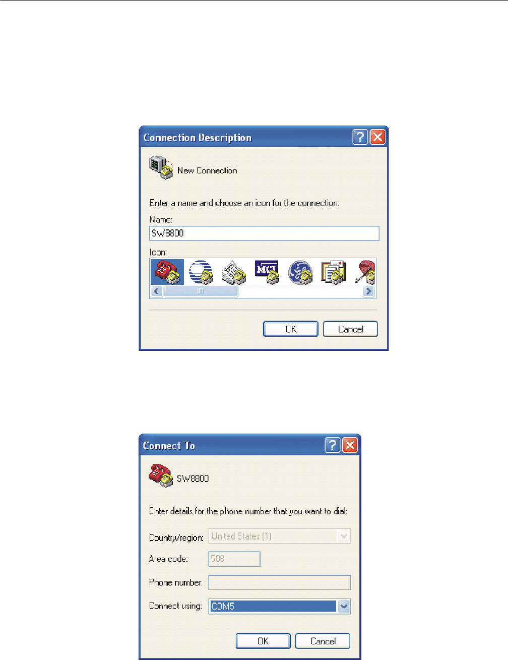
To set terminal parameters:
1Start the PC and select Start > Programs > Accessories > Communications >
HyperTerminal.
2The HyperTerminal window displays the Connection Description dialog box, as
shown in Figure 2.
Figure 2 Set Up the New Connection
3Enter the name of the new connection in the Name field and click OK. The dialog
box, shown in Figure 3 displays.
4Select the serial port to be used from the Connect using dropdown menu.
Figure 3 Properties Dialog Box
6CHAPTER 1: SYSTEM ACCESS
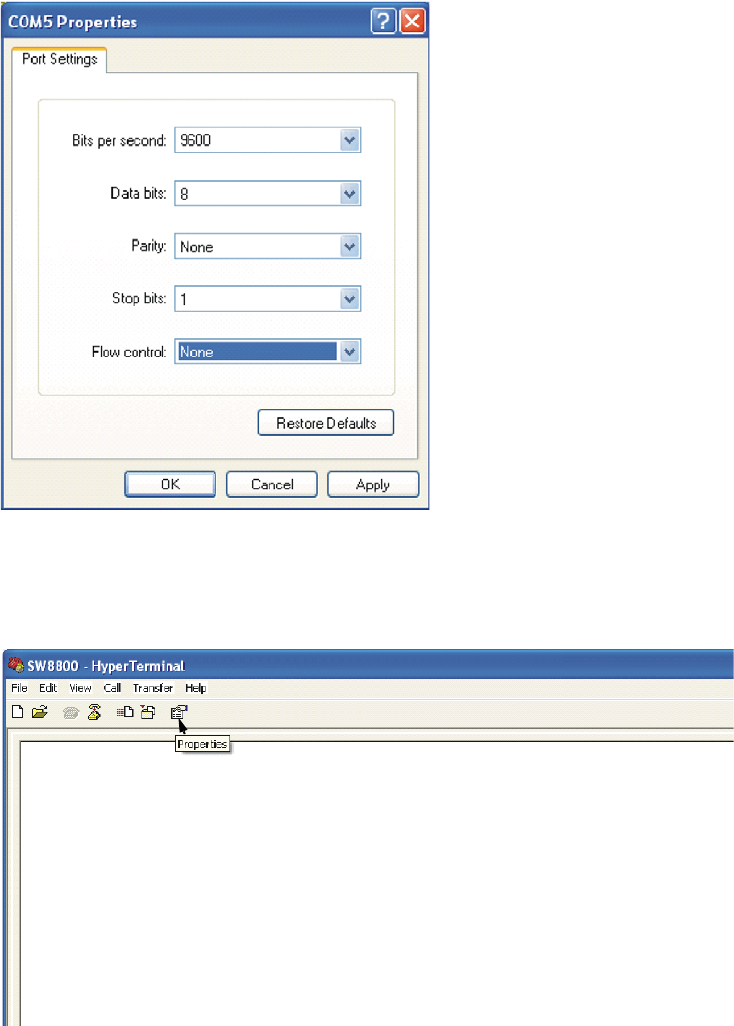
5Click OK. The Port Settings tab, shown in Figure 4, displays and you can set serial
port parameters. Set the following parameters:
■Baud rate = 9600
■Databit = 8
■Parity check = none
■Stopbit = 1
■Flow control = none
Figure 4 Set Communication Parameters
6Click OK. The HyperTerminal dialogue box displays, as shown in Figure 5.
7Select Properties.
Figure 5 HyperTerminal Window
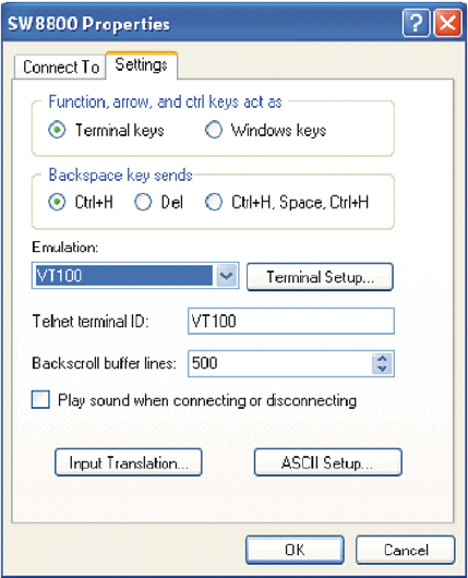
Setting Terminal Parameters 7
8In the Properties dialog box, select the Settings tab, as shown in Figure 6.
9Select VT100 in the Emulation dropdown menu.
10 Click OK.
Figure 6 Settings Tab
Setting the Terminal Parameters is described in the following sections:
■Configuring Through Telnet
■Configuring Through a Dial-up Modem
■Configuring the User Interface
Configuring Through
Tel n et
Before you can telnet to a Switch 8800 and configure it, you must:
1Configure the IP address of a VLAN interface for the Switch 8800 through the
console port (using the ip address command in VLAN interface view)
2Add the port (that connects to a terminal) to this VLAN (using the port command
in VLAN view)
3Log in to the Switch 8800
Tasks for Configuring through Telnet are described in the following sections:
■Connecting the PC to the Switch 8800
■Connecting Two Switch 8800 Systems
8CHAPTER 1: SYSTEM ACCESS
Connecting the PC to the Switch 8800
To connect the PC and Switch 8800 through Telnet:
1Authenticate the Telnet user through the console port before the user logs in by
Tel net.
By default, a password is required for authenticating the Telnet user to log in the
Switch 8800. If a user logs in by Telnet without a password, the user sees the
message: Login password has not been set!
2Enter system view, return to user view by pressing Ctrl+Z.
<SW8800>system-view
[SW8800]user-interface vty 0 4
[SW8800-ui-vty0]set authentication password simple/cipher xxxx
(xxxx is the preset login password of Telnet user)
3To set up the configuration environment, connect the Ethernet port of the PC to
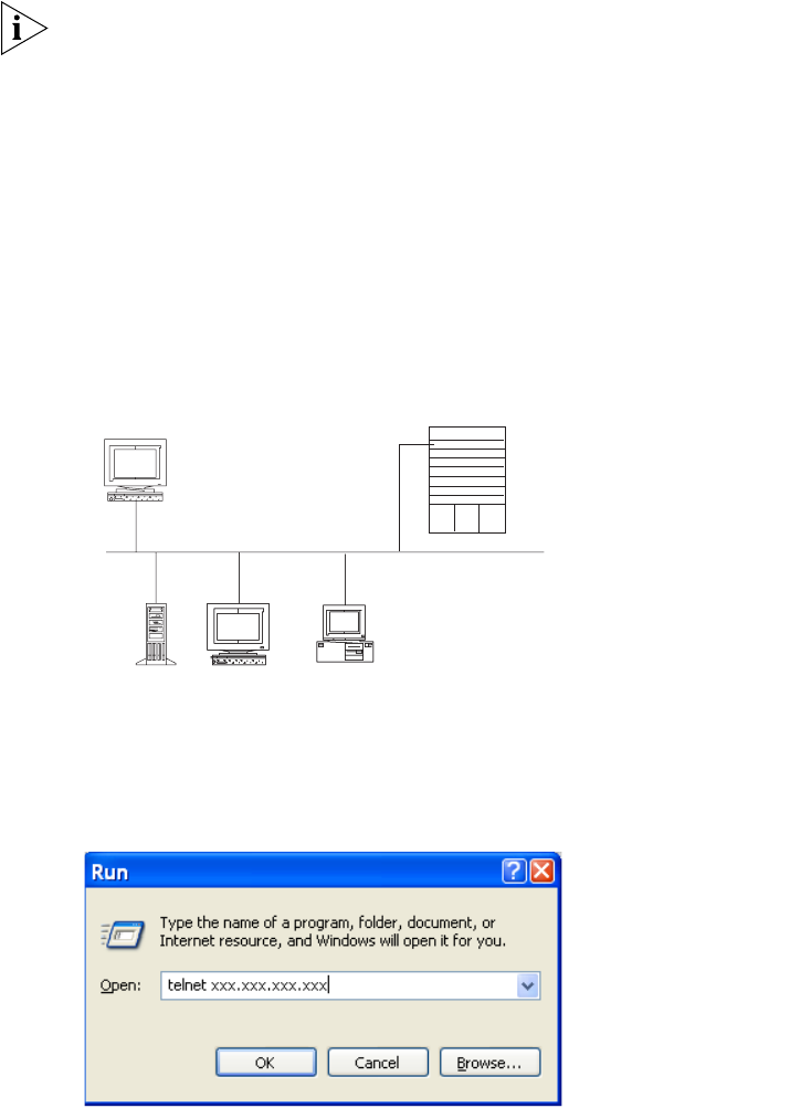
that of the Switch 8800 through the LAN. See Figure 7.
Figure 7 Setting Up the Configuration Environment Through Telnet
4Run Telnet on the PC by selecting Start > Run from the Windows desktop and
entering Telnet in the Open field, as shown in Figure 8. Click OK.
Figure 8 Run Telnet
The terminal displays User Access Verification and prompts you for the logon
password.
5Enter the password. The terminal displays the command line prompt (<SW8800>).
If the message, Too many users! appears, try to reconnect later. At most, 5
Telnet users are allowed to log on to a Switch 8800 simultaneously.
Workstation
WorkstationServer
Switch 8800
Ethernet port
PC (for configuring
the switch through Telnet)
Ethernet
Setting Terminal Parameters 9
6Use the appropriate commands to configure the Switch 8800 or to monitor the
operational state. Enter ? to get immediate help. For details on specific
commands, refer to the chapters in this guide.
When configuring the Switch 8800 by Telnet, do not modify the IP address unless
necessary, because the modification might terminate the Telnet connection. By
default, after passing the password authentication and logging on, a Telnet user
can access the commands at login level 0.
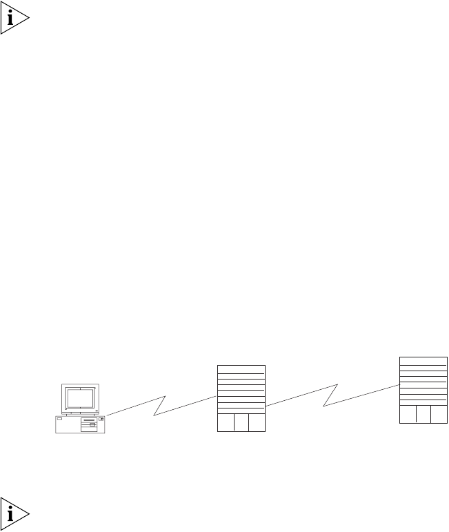
Connecting Two Switch 8800 Systems
Before you can telnet the Switch 8800 to another Switch 8800, as shown in
Figure 9, you must:
1Configure the IP address of a VLAN interface for the Switch 8800 through the
console port (using the ip address command in VLAN interface view)
2Add the port (that connects to a terminal) to this VLAN (using the port command
in VLAN view)
3Log in to the Switch 8800
After you telnet to a Switch 8800, you can run the telnet command to log in and
configure another Switch 8800.
Figure 9 Provide Telnet Client Service
1Authenticate the Telnet user through the console port on the Telnet Server (Switch
8800) before login.
By default, a password is required for authenticating the Telnet user to log in the
Switch 8800. If a user logs into Telnet without password, the system displays the
following message: Login password has not been set!
2Enter system view, return to user view by pressing Ctrl+Z.
<SW8800>system-view
[SW8800]user-interface vty 0
[SW8800-ui-vty0]set authentication password simple/cipher xxxx (xxxx
is the preset login password of Telnet user)
3Log in to the Telnet client (Switch 8800). For the login process, see “Connecting
the PC to the Switch 8800”.
4Perform the following operations on the Telnet client:
<SW8800>telnet xxxx
(XXXX can be the hostname or IP address of the Telnet Server. If it is the hostname,
you need to use the ip host command to specify it).
5Enter the preset login password. The Switch 8800 prompt (<SW8800>) displays. If
the message, Too many users! displays, try to connect later.
PC Telnet client Telnet server
10 CHAPTER 1: SYSTEM ACCESS
6Use the appropriate commands to configure the Switch 8800 or view its
operational state. Enter ? to get immediate help. For details on a specific
command, refer to the appropriate chapter in this guide.
Configuring Through a
Dial-up Modem
To configure your router with a dial-up modem through the AUX port:
1Authenticate the modem user through the console port of the Switch 8800 before
the user logs in to the switch through a dial-up modem.
By default, a password is required for authenticating the modem user to log in to
the Switch 8800. If a user logs in through the modem without a password, the
user sees the message, Password required, but none set.
aEnter system view, return user view with Ctrl+Z.
<SW8800>system-view
[SW8800]user-interface aux 0
[SW8800-ui-aux0]set authentication password simple/cipher xxxx (xxxx
is the preset login password of the Modem user.)
bUsing the modem command, you can configure the console port to modem
mode.
[SW8800-ui-aux0]modem
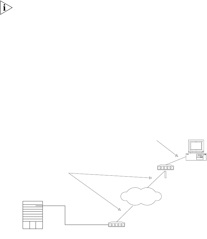
2To set up the remote configuration environment, connect the modems to a PC (or
a terminal) serial port and to the Switch 8800 console port, as shown in Set Up
Remote Configuration Environment.
Figure 10 Set Up Remote Configuration Environment
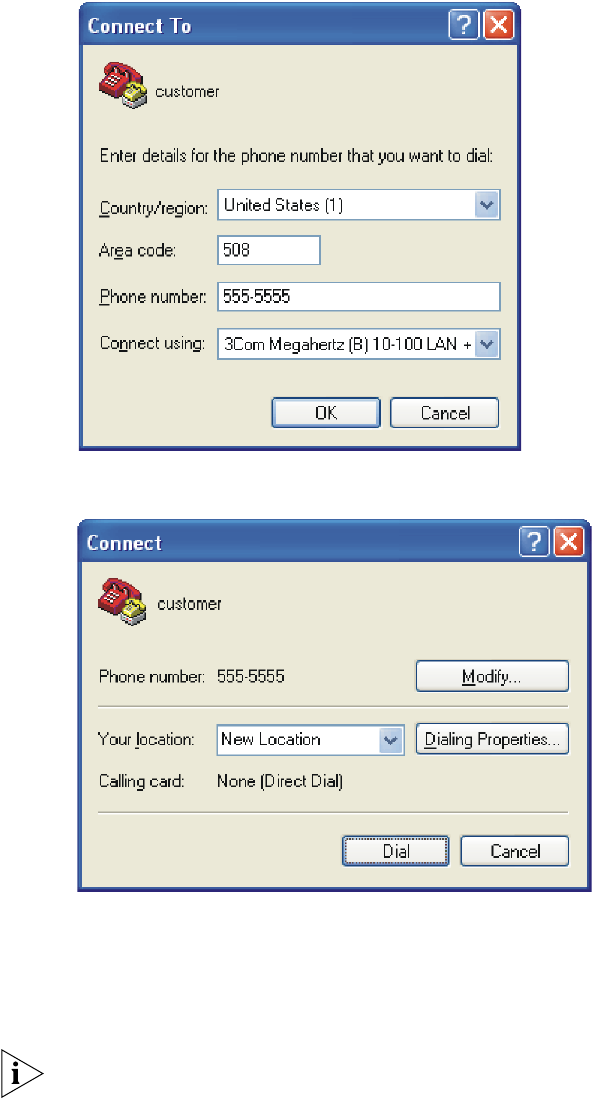
3Dial for a connection to the switch, using the terminal emulator and modem on
the remote end. Dial the telephone number of the modem connected to the
Switch 8800. See Figure 11 and Figure 12.
Console port
Remote telephone:
555-5555
Modem
Modem
PST
Telephone line
Modem serial port line
Setting Terminal Parameters 11
Figure 11 Set the Dialed Number
Figure 12 Dial the Remote PC
4Enter the preset login password on the remote terminal emulator and wait for the
<SW8800>prompt.
5Use the appropriate commands to configure the Switch 8800 or view its
operational state. Enter ? to get immediate help. For details on a specific
command, refer to the appropriate chapter in this guide.
By default, after login, a modem user can access the commands at Level 0.
Configuring the User
Interface
User interface configuration is another way to configure and manage port data.
The Switch 8800 supports the following configuration methods:
■Local configuration through the console port
■Remote configuration through Telnet on the Ethernet port

12 CHAPTER 1: SYSTEM ACCESS
■Remote configuration through a modem through the console port.
There are two types of user interfaces:
■AUX user interface is used to log in the Switch 8800 through a dial-up modem.
A Switch 8800 can only have one AUX port.
■VTY user interface is used to telnet the Switch 8800.
For the Switch 8800, the AUX port and Console port are the same port. There is
only the type of AUX user interface.
The user interface is numbered by absolute number or relative number.
To number the user interface by absolute number:
■The AUX user interface is the first interface — user interface 0.
■The VTY is numbered after the AUX user interface. The absolute number of the
first VTY is the AUX user interface number plus 1.
To number the user interface by relative number, represented by interface +
number assigned to each type of user interface:
■AUX user interface = AUX 0.
■The first VTY interface = VTY 0, the second one = VTY 1, and so on.
Tasks for configuring the user interface are described in the following sections:
■Entering the User Interface View
■Configuring the Attributes of the AUX (Console) Port
■Configuring the Terminal Attributes
■Managing Users
■Configuring the Attributes of a Modem
■Configuring Redirection
■Displaying and Debugging User Interface
Entering the User Interface View
Use the user-interface command (see Table 2) to enter a user interface view. You
can enter a single user interface view or multi-user interface view to configure one
or more user interfaces.
Perform the following configuration in system view.
Configuring the Attributes of the AUX (Console) Port
Use the speed, flow control, parity, stop bit, and data bit commands (see
Tab le 3) to configure these attributes of the AUX (Console) port.
Tab le 2 Enter User Interface View
Operation Command
Enter a single user interface view or multi user
interface views
user-interface [ type ] first-number [
last-number ]

Setting Terminal Parameters 13
Perform the following configurations in user interface (AUX user interface only)
view.
Configuring the Terminal Attributes
The following commands can be used for configuring the terminal attributes,
including enabling/disabling terminal service, disconnection upon timeout,
lockable user interface, configuring terminal screen length and history command
buffer size.
Perform the following configuration in user interface view. Perform the lock
command in user view.
Enabling and Disabling Terminal Service After the terminal service is
disabled on a user interface, you cannot log in to the Switch 8800 through the
user interface. However, if a user logged in through the user interface before
disabling the terminal service, the user can continue operation. After the user logs
out, the user cannot log in again. In this case, the user can log in to the Switch
through the user interface only when the terminal service is enabled again. Use
the commands described in Tabl e 4 to enable or disable terminal service.
Table 3 Configure the Attributes of the AUX (Console) Port
Operation Command
Configure the transmission speed on AUX
(Console) port. By default, the transmission
speed is 9600bps
speed speed-value
Restore the default transmission speed on
AUX (Console) port
undo speed
Configure the flow control on AUX (Console)
port. By default, no flow control is performed
on the AUX (Console) port
flow-control { hardware | none |
software }
Restore the default flow control mode on AUX
(Console) port
undo flow-control
Configure parity mode on the AUX (Console)
port. By default, there is no parity bit on the
AUX (Console) port
parity { even | mark | none | odd | space }
Restore the default parity mode undo parity
Configure the stop bit of AUX (Console) port.
By default, AUX (Console) port supports 1
stop bit
stopbits { 1 | 1.5 | 2 }
Restore the default stop bit of AUX (Console)
port
undo stopbits
Configure the data bit of AUX (Console) port.
By default, AUX (Console) port supports 8
data bits.
databits { 7 | 8 }
Restore the default data bit of AUX (Console)
port
undo databits
Table 4 Enabling and Disabling Terminal Service
Operation Command
Enable terminal service shell
Disable terminal service undo shell

14 CHAPTER 1: SYSTEM ACCESS
By default, terminal service is enabled on all the user interfaces.
Note the following points:
■For the sake of security, the undo shell command can only be used on the user
interfaces other than the AUX user interface.
■You cannot use this command on the user interface through which you log in.
■You must confirm your privilege before using the undo shell command in any
legal user interface.
Configuring idle-timeout By default, idle-timeout is enabled and set to 10
minutes on all the user interfaces. The idle-timeout command is described in
Tab le 5.
Locking the User Interface The lock command locks the current user interface
and prompts the user to enter a password. This makes it impossible for others to
operate in the interface after the user leaves. The lock command is described in
Tab le 6.
Setting the Screen Length If a command displays more than one screen of
information, you can use the screen length command to determine how many
lines are displayed on a screen so that information can be separated in different
screens and you can view it more conveniently. The screen-length command is
described in Tab l e 7.
By default, the terminal screen length is 24 lines.
Setting the History-Command Buffer Size
Tab le 8 describes the history-command max-size command.
By default, the size of the history-command max-size command buffer is 10.
Tab le 5 Idle Timeout
Operation Command
Configure idle-timeout idle-timeout minutes [ seconds ]
(idle-timeout 0 means disabling
idle-timeout.)
Restore the default idle-timeout undo idle-timeout
Tab le 6 Lock User Interface
Operation Command
Lock user interface lock
Tab le 7 Setting Screen Length
Operation Command
Set the screen length screen-length screen-length (screen-length
0 indicates to disable screen display separation
function.)
Restore the default screen length undo screen-length
Tab le 8 Set the History Command Buffer Size
Operation Command
Set the history command buffer size history-command max-size value

Setting Terminal Parameters 15
Managing Users
The management of users includes, the setting of the user logon authentication
method, the level of command a user can use after logging on, the level of
command a user can use after logging on from the specific user interface, and the
command level.
Configuring the Authentication Method The authentication-mode
command configures the user login authentication method that allows access to
an unauthorized user. Tab l e 9 describes the authentication-mode command.
Perform the following configuration in user interface view.
By default, terminal authentication is not required for users who log in through
the console port, whereas a password is required for authenticating modem and
Telnet users when they log in.
To configure authentication for modem and Telnet users:
1Configure local password authentication for the user interface.
When you set the password authentication mode, you must also configure a login
password to log in successfully. Ta ble 10 describes the set authentication
password command.
Perform the following configuration in user interface view.
Configure for password authentication when a user logs in through a VTY 0 user
interface and set the password to 3Com:
[SW8800]user-interface vty 0
[SW8800-ui-vty0]authentication-mode password
[SW8800-ui-vty0]set authentication password simple 3Com
2Configure the local or remote authentication username and password.
Use the authentication-mode scheme command to perform local or remote
authentication of username and password. The type of the authentication
depends on your configuration. For detailed information, see “AAA and RADIUS
Operation”
Restore the default history command buffer
size
undo history-command max-size
Table 9 Configure Authentication Method
Operation Command
Configure the authentication method authentication-mode { password | scheme
}
Configure no authentication authentication-mode none
Table 8 Set the History Command Buffer Size
Operation Command
Table 10 Configure the Local Authentication Password
Operation Command
Configure the local authentication password set authentication password { cipher |
simple } password
Remove the local authentication password undo set authentication password

16 CHAPTER 1: SYSTEM ACCESS
Perform username and password authentication when a user logs in through the
VTY 0 user interface and set the username and password to zbr and 3Com
respectively:
[SW8800-ui-vty0]authentication-mode scheme
[SW8800-ui-vty0]quit
[SW8800]local-user zbr
[SW8800-luser-zbr]service-type telnet
[SW8800-luser-zbr]password simple 3Com
3Set the Switch 8800 to allow user access without authentication.
[SW8800-ui-vty0]authentication-mode none
By default, the password is required for authenticating the modem and Telnet
users when they log in. If the password has not been set, when a user logs in, the
following message displays, Login password has not been set!
If the authentication-mode none command is used, the modem and Telnet
users are not required to enter a password.
Set the Command Level after Login The following command is used for
setting the command level used after a user logs in.
Perform the following configuration in local-user view.
By default, a Telnet user can access the commands at Level 1 after logon.
Setting the Command Level Used after a User Logs in from a User Interface
Use the user privilege level command to set the command level, after a user
logs in from a specific user interface, so that a user is able to execute the
commands at that command level. Ta ble 12 describes the user privilege level
command.
Perform the following configuration in user interface view.
By default, a user can access the commands at Level 3 after logging in through the
AUX user interface, and the commands at Level 0 after logging in through the VTY
user interface.
Tab le 11 Set Command Level Used After a User Logs In
Operation Command
Set the command level used after a user
logging in
service-type { level level | telnet [ level level
] ] | telnet [ level level ] }
Restore the default command level used after
a user logging in
undo service-type { level | telnet [ level ] ] |
telnet [ level ] }
Tab le 12 Set Command Level After User Login
Operation Command
Set command level used after a user logging
in from a user interface
user privilege level level
Restore the default command level used after
a user logging in from a user interface
undo user privilege level

Setting Terminal Parameters 17
When a user logs in to the switch, the command level that the user can access
depends on two points. One is the command level that the user can access, the
other is the set command level of the user interface. If the two levels are different,
the former is taken. For example, the command level of VTY 0 user interface is 1,
however, user Tom has the right to access commands of level 3; if Tom logs in from
VTY 0 user interface, he can access commands of level 3 and lower.
Setting Command Priority The command-privilege level command sets the
priority of a specified command in a certain view. The command levels include
visit, monitoring, configuration, and management, which are identified with
command level 0 through 3, respectively. An administrator assigns authority
according to user requirements. See Table 13.
Perform the following configuration in system view.
Configuring the Attributes of a Modem
You can use the commands described in Table 14 to configure the attributes of a
modem when logging in to the Switch through the modem.
Perform the following configuration in user interface view.
Configuring Redirection
The send Command can be used for sending messages between user
interfaces. See Table 15.
Table 13 Set Command Priority
Operation Command
Set the command priority in a specified view. command-privilege level level view view
command
Restore the default command level in a
specified view.
undo command-privilege view view
command
Table 14 Configure Modem
Operation Command
Set the interval since the system receives the
RING until CD_UP
modem timer answer seconds
Restore the default interval since the system
receives the RING until CD_UP
undo modem timer answer
Configure auto answer modem auto-answer
Configure manual answer undo modem auto-answer
Configure to allow call-in modem call-in
Configure to bar call-in undo modem call-in
Configure to permit call-in and call-out. modem both
Configure to disable call-in and call-out undo modem both

18 CHAPTER 1: SYSTEM ACCESS
Perform the following configuration in user view.
The auto-execute Command is used to run a command automatically after
you log in. The command is automatically executed when you log in again. See
Tab le 16.
This command is usually used to execute the telnet command automatically on a
terminal, which connects the user to a designated device.
Perform the following configuration in user interface view.
After applying the auto-execute command, the user interface can no longer be
used to carry out the routine configurations for the local system.
Make sure that you will be able to log in to the system in some other way and
cancel the configuration before you use the auto-execute command and save
the configuration.
Telnet 10.110.100.1 after the user logs in through VTY0 automatically.:
[SW8800-ui-vty0]auto-execute command telnet 10.110.100.1
When a user logs on by VTY 0, the system will run telnet 10.110.100.1
automatically.
Displaying and Debugging User Interface
After creating the previous configuration, execute the display command in all
views to display the user interface configuration, and to verify the effect of the
configuration. Execute the free command in user view to clear a specified user
interface.
See Table 17.
Tab le 15 Configure to Send Messages Between User Interfaces
Operation Command
Configure to send messages between
different user interfaces.
send { all | number | type number }
Tab le 16 Configure Automatic Command Execution
Operation Command
Configure to automatically run the command auto-execute command text
Configure not to automatically run the
command
undo auto-execute command
Tab le 17 Display and Debug User Interface
Operation Command
Clear a specified user interface free user-interface [ type ] number
Display the user application information of the
user interface
display users [ all ]
Display the physical attributes and some
configurations of the user interface
display user-interface [ type number ] [
number ] [summary]

Command Line Interface 19
Command Line
Interface
The Switch 8800 provides a series of configuration commands and command line
interfaces for configuring and managing the Switch 8800. The command line
interface has the following features.
■Local configuration through the console and AUX ports.
■Local or remote configuration through Telnet.
■Remote configuration through a dial-up Modem through the AUX port to log
in to the Switch 8800.
■Hierarchy command protection to prevent unauthorized users from accessing
the switch.
■Access to online Help by entering ?.
■Network test commands, such as Tracert and Ping, for rapid troubleshooting of
the network.
■Detailed debugging information to help with network troubleshooting.
■Ability to log in and manage other Switch 8800s directly, using the telnet
command.
■FTP service for the users to upload and download files.
■Ability to view previously executed commands.
■The command line interpreter that searches for a target not fully matching the
keywords. You can enter the whole keyword or part of it, as long as it is unique
and not ambiguous.
Configuring a Command Line Interface is described in the following sections:
■Command Line View
■Features and Functions of the Command Line
Command Line View The Switch 8800 provides hierarchy protection for the command lines to prevent
unauthorized users from accessing the switch illegally.
There are four levels of commands:
■Visit level — involves commands for network diagnosis tools (such as ping and
tracert), command of the switch between different language environments of
user interface (language-mode) and the telnet command. Saving the
configuration file is not allowed on this level of commands.
■Monitoring level — includes the display command and the debugging
command for system maintenance, service fault diagnosis, and so on. Saving
the configuration file is not allowed on this level of commands.
■Configuration level — provides service configuration commands, such as the
routing command and commands on each network layer that are used to
provide direct network service to the user.
■Management level — influences the basic operation of the system and the
system support module which plays a support role for service. Commands at
this level involve file system commands, FTP commands, TFTP commands,
XModem downloading commands, user management commands, and level
setting commands.
20 CHAPTER 1: SYSTEM ACCESS
Login users are also classified into four levels that correspond to the four
command levels. After users of different levels log in, they can only use commands
at their own, or lower, levels.
To prevent unauthorized users from illegal intrusion, users are identified when
switching from a lower level to a higher level with the super [ level ] command.
User ID authentication is performed when users at a lower level switch to users at
a higher level. Only when correct password is entered three times, can the user
switch to the higher level. Otherwise, the original user level remains unchanged.
Command views are implemented according to requirements that are related to
one another. For example, after logging in to the Switch 8800, you enter user
view, in which you can only use some basic functions, such as displaying the
operating state and statistics information. In user view, key in system-view to
enter system view, in which you can key in different configuration commands and
enter the corresponding views.
The command line provides the following views:
■User view
■System view
■Ethernet Port view
■VLAN view
■VLAN interface view
■Local-user view
■User interface view
■FTP client view
■PIM view
■RIP view
■OSPF view
■OSPF area view
■Route policy view
■Basic ACL view
■Advanced ACL view
■Layer-2 ACL view
■RADIUS server group view
■ISP domain view
■BGP view
■ISIS view
The relation diagram of the views is shown in Figure 13.
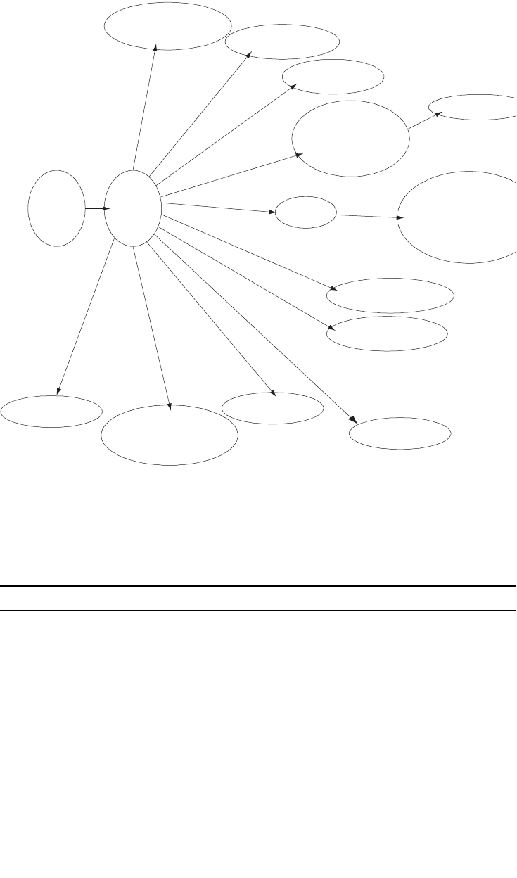
Command Line Interface 21
Figure 13 Relation Diagram of the Views
Tabl e 18 describes the function features of different views.
For all views, use the quit command to return to system view and use the return
command to return to user view.
Table 18 Function Feature of Command View
Command view Function Prompt Command to enter
User view Show basic infor-
mation about
operation and
statistics
<SW8800> Enter right after
connecting the switch
System view Configure system
parameters
[SW8800] Key in system-view
in user view
Ethernet Port view Configure Ethernet
port parameters
[SW8800-Gigabit
Ethernet1/1/1]
100M Ethernet port
view
[SW8800-Gigabit
Ethernet1/1/1]
Gigabit Ethernet port
view
VLAN view Configure VLAN
parameters
[SW8800-
Vlan1]
Enter vlan 1 in
System view
VLAN interface view Configure IP interface
parameters for a
VLAN or a VLAN
aggregation
[SW8800-Vlan-in
terface1]
Enter interface
vlan-interface 1 in
System view
Ethernet port view
User interface view
VLAN view
VLAN interface view
User view System
view
RIP view
OSPF view
Route policy view
OSPF area view
Basic ACL view
Advanced ACL view
Interface-based ACL view
Layer-2 ACL view
FTP client view
Local-user view
PIM view
RADIUS server group view
ACL
BGP view
IS-IS view

22 CHAPTER 1: SYSTEM ACCESS
Features and Functions
of the Command Line
Tasks for configuring the features and functions of the command line are
described as follows:
■Online Help
■Common Command Line Error Messages
■History Command
■Editing Features of the Command Line
■Displaying Features of the Command Line
Online Help
The command line interface provides full and partial online Help modes.
You can get the help information through these online help commands, which are
described as follows.
■Enter ? in any view to get all the commands in it and corresponding
descriptions.
<SW8800>?
User view commands:
language-mode Specify the language environment
ping Ping function
Local-user view Configure local user
parameters
[SW8800-user-
user1]
Enter local-user
user1 in System view
User interface view Configure user
interface parameters
[SW8800-ui0] Enter user-interface
0 in System view
FTP Client view Configure FTP Client
parameters
[ftp] Enter ftp in user view
PIM view Configure PIM
parameters
[SW8800-PIM] Enter pim in System
view
RIP view Configure RIP
parameters
[SW8800-rip] Enter rip in System
view
OSPF view Configure OSPF
parameters
[SW8800-ospf] Enter ospf in System
view
OSPF area view Configure OSPF area
parameters
[SW8800-ospf-0.
0.0.1]
Enter area 1 in OSPF
view
Route policy view Configure route policy
parameters
[SW8800-route-
policy]
Enter route-policy
policy1 permit node
10 in System view
Basic ACL view Define the rule of
basic ACL
[SW8800-acl-
basic-2000]
Enter acl number
2000 in System view
Advanced ACL view Define the rule of
advanced ACL
[SW8800-acl-adv
-3000]
Enter acl number
3000 in System view
Layer-2 ACL view Define the rule of
layer-2 ACL
[SW8800-acl-
link-4000]
Enter acl number
4000 in System view
RADIUS server group
view
Configure radius
parameters
[SW8800-radius-
1]
Enter radius scheme
1 in System view
ISP domain view Configure ISP domain
parameters
[SW8800-isp-163
.net]
Enter domain
isp-163.net in System
view
Table 18 Function Feature of Command View (continued)
Command view Function Prompt Command to enter
Command Line Interface 23
quit Exit from current command view
super Enter the command workspace with specified user priority
level
telnetEstablish one TELNET connection
tracertTrace route function
■Enter a command with a ?, separated by a space. If this position is for
keywords, then all the keywords and the corresponding brief descriptions will
be listed.
<SW8800>ping ?
-a Select source IP address
-c Specify the number of echo requests to send
-d Specify the SO_DEBUG option on the socket being used
-h Specify TTL value for echo requests to be sent
-I Select the interface sending packets
-n Numeric output only. No attempt will be made to lookup host
addresses for symbolic names
-p No more than 8 "pad" hexadecimal characters to fill out the sent
packet. For example, -p f2 will fill the sent packet with f and 2
repeatedly
-q Quiet output. Nothing is displayed except the summary lines at
startup time and when finished
-r Record route. Includes the RECORD_ROUTE option in the ECHO_REQUEST
packet and displays the route
-s Specifies the number of data bytes to be sent
-t Timeout in milliseconds to wait for each reply
-v Verbose output. ICMP packets other than ECHO_RESPONSE that are
received are listed
STRING<1-20> IP address or hostname of a remote system
Ip IP Protocol
■Enter a command with a ?, separated by a space. If this position is for
parameters, all the parameters and their brief descriptions will be listed.
[SW8800]garp timer leaveall ?
INTEGER<65-32765> Value of timer in centiseconds
(LeaveAllTime > (LeaveTime [On all ports]))
Time must be multiple of 5 centiseconds
[SW8800]garp timer leaveall 300 ?
<cr>
<cr> indicates no parameter in this position. The next command line repeats
the command, you can press Enter to execute it directly.
■Enter a character string with a ?, and list all the commands beginning with this
character string.
<SW8800>p?
ping
■Input a command with a character string and ?, and list all the key words
beginning with this character string in the command.
<SW8800>display ver?
version

24 CHAPTER 1: SYSTEM ACCESS
Common Command Line Error Messages
All the commands that are entered by users can be correctly executed if they have
passed the grammar check. Otherwise, error messages are reported to users.
Common error messages are listed in Tab l e 19.
History Command
The command line interface provides a function similar to DosKey. The commands
entered by users can be automatically saved by the command line interface and
you can invoke and execute them at any time. By default, the history command
buffer can store 10 history commands for each user. The operations are shown in
Tab le 20.
Editing Features of the Command Line
The command line interface provides a basic command editing function and
supports editing multiple lines. A command cannot be longer than 256 characters.
See Table 21.
Tab le 19 Common Command Line Error Messages
Error messages Causes
Unrecognized command Cannot find the command.
Cannot find the keyword. Wrong parameter type.
The value of the parameter exceeds the range. Incomplete command
The command is incomplete. Too many parameters
You entered too many parameters. Ambiguous command
The parameters you entered are not specific.
Tab le 20 Retrieve History Command
Operation Key Result
Display history command display history-command Displays history commands
by the user who is entering
them.
Retrieve the previous history
command
Up cursor key <> or <Ctrl+P> Retrieves the previous history
command, if there is any.
Retrieve the next history
command
Down cursor key <> or
<Ctrl+N>
Retrieves the next history
command, if there is any.
Tab le 21 Editing Functions
Key Function
Common keys Inserts at the cursor position and the cursor
moves to the right, if the edition buffer still
has free space.
Backspace Deletes the character preceding the cursor
and the cursor moves backward.
Left cursor key < or Ctrl+B Moves the cursor a character backward
Right cursor key > or Ctrl+F Moves the cursor a character forward
Up cursor key ^ or Ctrl+P
Down cursor key v or Ctrl+N
Retrieves the history command.

Command Line Interface 25
Displaying Features of the Command Line
If information to be displayed exceeds one screen, the pause function allows users
three choices, as described in Table 22.
Tab Press Tab after typing the incomplete key
word and the system will execute the partial
help: If the key word matching the typed one
is unique, the system will replace the typed
one with the complete key word and display it
in a new line. If there is not a matched key
word or the matched key word is not unique,
the system will do no modification but
displays the originally typed word in a new
line.
Table 22 Display Functions
Key or Command Function
Press Ctrl+C when the display pauses Stop displaying and executing command.
Enter a space when the display pauses Continue to display the next screen of
information.
Press Enter when the display pauses Continue to display the next line of
information.
Table 21 Editing Functions
Key Function
26 CHAPTER 1: SYSTEM ACCESS

2PORT CONFIGURATION
This chapter covers the following topics:
■Ethernet Port Overview
■Configuring Link Aggregation
Ethernet Port
Overview
The following features are found in the Ethernet ports of the Switch 8800:
■10GBASE-X-XENPAK 10-Gigabit Ethernet ports work in 10-gigabit full duplex
mode.
■10GBASE-X-XFP operates in 10 Gbps full duplex mode, which needs no
configuring.
■1000BASE-X-SFP Gigabit Ethernet ports work in gigabit full duplex mode.
■10/100/1000BASE-T Gigabit Ethernet ports support MDI/MDI-X auto-sensing,
and the modes are 1000 Mbps full duplex, 100 Mbps half/full duplex, and 10
Mbps half/full duplex. These modules also support auto-negotiation
Configuring an Ethernet port is described in the following sections:
■Configuring Ethernet Ports
■Example: Configuring the Default VLAN ID of the Trunk Port
■Troubleshooting VLAN Port Configuration
Configuring Ethernet
Ports
Tasks for configuring Ethernet ports are described in the following sections:
■Entering Ethernet Port View
■Enabling and Disabling Ethernet Ports
■Setting the Description Character String for an Ethernet Port
■Setting the Duplex Attribute of the Ethernet Port
■Setting the Speed of the Ethernet Port
■Setting the Cable Type for an Ethernet Port
■Setting Flow Control for an Ethernet Port
■Permitting/Forbidding Jumbo Frames on the Ethernet port
■Setting the Maximum MAC Addresses an Ethernet Port Can Learn
■Setting the Link Type for an Ethernet Port
■Adding an Ethernet Port to a VLAN
■Setting the Default VLAN ID for an Ethernet Port
■Copying a Port Configuration to Other Ports
28 CHAPTER 2: PORT CONFIGURATION
■Displaying and Debugging Ethernet Ports
Entering Ethernet Port View
Before configuring the Ethernet port, enter Ethernet port view.
Perform the following configuration in system view.
The subslot on the Fabric is always set to 1.
Enabling and Disabling Ethernet Ports
The following command can be used for disabling or enabling the port. After
configuring the related parameters and protocol of the port, you can use the
following command to enable the port.
Perform the following configuration in Ethernet port view.
By default, the port is enabled.
Setting the Description Character String for an Ethernet Port
You can use the following command to identify the Ethernet ports.
Perform the following configuration in Ethernet port view.
By default, the port description is a null character string.
Setting the Duplex Attribute of the Ethernet Port
Set the port to full duplex to send and receive data packets at the same time. Set
the port to half-duplex to either send or receive only. If the port has been set to
auto-negotiation mode, the local and peer ports will automatically negotiate the
duplex mode.
Tab le 1 Enter Ethernet Port View
Operation Command
Enter Ethernet port view interface { Gigabit | Ethernet }
slot/subslot/port
Tab le 2 Enable/Disable an Ethernet Port
Operation Command
Disable an Ethernet port shutdown
Enable an Ethernet port undo shutdown
Tab le 3 Set Description Character String for Ethernet Port
Operation Command
Set description character string for Ethernet
port.
description text
Delete the description character string of
Ethernet.
undo description
Ethernet Port Overview 29
Perform the following configuration in Ethernet port view.
The Gigabit Ethernet Base-T ports can operate in full duplex, half duplex, or
auto-negotiation mode. When the ports operate at 1000 Mbps, the duplex mode
can be set to full (full duplex) or auto (auto-negotiation).
By default, the port is in auto (auto-negotiation) mode.
Setting the Speed of the Ethernet Port
You can use the following command to set the speed on the Ethernet port. If the
speed is set to auto (auto-negotiation) mode, the local and peer ports will
automatically negotiate the port speed.
Perform the following configuration in Ethernet port view.
The Gigabit Ethernet BASE-T port can operate at 10 Mbps, 100 Mbps, or 1000
Mbps. However in half duplex mode, the port cannot operate at 1000 Mbps. The
Gigabit optical Ethernet port supports1000 Mbps; the 10 Gigabit optical Ethernet
port supports 10000 Mbps, which does not need to be configured.
Setting the Cable Type for an Ethernet Port
The Ethernet port supports the straight-through (MDI) and cross-over (MDIX)
network cables. The Switch 8800 only supports auto (auto-sensing). If you set
some other type, you will see an error message. By default, the cable type is auto
(auto-recognized). The system will automatically recognize the type of cable
connecting to the port.
Perform the following configuration in Ethernet port view. The settings only take
effect on 10/100/1000 Mbps electrical ports.
Setting Flow Control for an Ethernet Port
If flow control is enabled on both the local and the peer switch and congestion
occurs in the local switch, the local switch can instruct its peer to temporarily stop
sending packets. Once the peer switch receives this message, it stops sending
Table 4 Set the Duplex Attribute for an Ethernet Port
Operation Command
Set the duplex attribute for an Ethernet port. duplex {auto | full | half}
Restore the default duplex attribute of
Ethernet port.
undo duplex
Table 5 Set Speed on Ethernet Port
Operation Command
Set Ethernet port speed speed {10 | 100 | 1000 | auto}
Restore the default speed on Ethernet port undo speed
Table 6 Set the Type of the Cable Connected to the Ethernet Port
Operation Command
Set the type of the cable connected to the
Ethernet port.
mdi { auto }
Restore the default type of the cable
connected to the Ethernet port.
undo mdi

30 CHAPTER 2: PORT CONFIGURATION
packets and packet loss is reduced. The flow control function of the Ethernet port
can be enabled or disabled using the following commands.
Perform the following configuration in Ethernet port view.
By default, Ethernet port flow control is disabled.
Permitting/Forbidding Jumbo Frames on the Ethernet port
Using the jumbo frame enable command, you can allow jumbo frames (1523 to
to 9216 bytes) to pass through the specified Ethernet port. Note that packets of
1518 to 1522 bytes, including the IEEE 802.1Q tagging are always allowed to pass
through Ethernet ports.
Jumbo frames are only allowed for Ethernet Type II frames. Most network
equipment, including NICs, switches, and routers are not capable of supporting
jumbo frames and will always discard these packets.
Perform the following configuration in Ethernet port view.
By default, jumbo frames are disabled.
Setting the Maximum MAC Addresses an Ethernet Port Can Learn
Use the following command to set a limit on the number of MAC addresses that
an Ethernet port will learn.
Perform the following configuration in Ethernet port view.
If the count parameter is set to 0, the port is not permitted to learn MAC address.
By default, there is no limit to the amount of the MAC addresses that an Ethernet
port can learn. However the number of MAC addresses a port can learn is still
restricted by the size of the MAC address table.
Tab le 7 Set Flow Control for Ethernet Port
Operation Command
Enable Ethernet port flow control flow-control
Disable Ethernet port flow control undo flow-control
Tab le 8 Permitting/Forbidding Jumbo Frames to Pass Through the Ethernet Port
Operation Command
Permit jumbo frame to pass through the
Ethernet port.
jumboframe enable [ jumboframe_value ]
Forbid jumbo frame to pass through the
Ethernet port.
undo jumboframe enable
Tab le 9 Set a Limit on the Number of MAC Addresses Learned by an Ethernet Port
Operation Command
Set a limit on the number of MAC addresses
learned by an Ethernet port
mac-address max-mac-count count
Restore the default limit on MAC addresses
learned by the Ethernet port
undo mac-address max-mac-count

Ethernet Port Overview 31
Setting the Ethernet Port Broadcast Suppression Ratio
You can use the following commands to restrict the broadcast traffic. Once the
broadcast traffic exceeds the value set by the user, the system maintains an
appropriate broadcast packet ratio by discarding the overflow traffic. This is done
to suppress broadcast storm, avoid congestion, and ensure good traffic flow.
The parameter indicates the maximum wire speed ratio of the broadcast traffic
allowed on the port. The smaller the ratio, the smaller the amount of broadcast
traffic allowed. If the ratio is 100%, broadcast storm suppression is not performed
on the port.
Perform the following configuration in Ethernet port view.
By default, 100% broadcast traffic is allowed to pass through and no broadcast
suppression is performed.
Setting the Link Type for an Ethernet Port
An Ethernet port can operate in three different link modes, access, hybrid, and
trunk. The management access port carries one VLAN only and is used for
connecting to the user’s computer.
A trunk port can belong to more than one VLAN and can transmit packets on
multiple VLANs. A hybrid port can also belong to more than one VLAN and
transmit packets on multiple VLANs.
However, the hybrid port allows packets from multiple VLANs to be sent without
tags but the trunk port only allows packets from the default VLAN to be sent
without tags.
Perform the following configuration in Ethernet port view.
A port on a switch can be configured as an access port, a hybrid port, or a trunk
port. However, to reconfigure between hybrid and trunk link types, you must first
restore the default, or access link type.
The default port link type is the access link type.
Table 10 Setting the Ethernet Port Broadcast Suppression Ratio
Operation Command
Set the Ethernet port broadcast suppression
ratio
broadcast-suppression pct
Restore the default Ethernet port broadcast
suppression ratio
undo broadcast-suppression
Table 11 Set the Link Type for an Ethernet Port
Operation Command
Configure the port as an access port port link-type access
Configure the port as a hybrid port port link-type hybrid
Configure the port as a trunk port port link-type trunk
Restore the default link type, that is, the
access port.
undo port link-type

32 CHAPTER 2: PORT CONFIGURATION
Adding an Ethernet Port to a VLAN
The following commands are used for adding an Ethernet port to a specified
VLAN. Access ports can be added to only one VLAN, while hybrid and trunk ports
can be added to multiple VLANs.
Perform the following configuration in Ethernet port view.
The access port will be added to an existing VLAN other than VLAN 1. The VLAN
to which a Hybrid port is added must exist. The VLAN to which a Trunk port is
added cannot be VLAN 1.
After adding the Ethernet port to the specified VLANs, the local port can forward
packets from these VLANs. The hybrid and trunk ports can be added to multiple
VLANs, thereby, implementing the VLAN intercommunication between peers. For
the hybrid port, you can tag VLAN packets to process packets in different ways,
depending on the target device.
Setting the Default VLAN ID for an Ethernet Port
An access port can only be included in one VLAN so its default VLAN is the VLAN
to which it belongs.
The hybrid port and the trunk port can be included in several VLANs but a default
VLAN ID must be configured. If the default VLAN ID has been configured, the
packets without a VLAN tag are forwarded to the port that belongs to the default
VLAN. When the system sends packets with a VLAN tag, if the VLAN ID of the
packet is identical to the default VLAN ID of the port, the system will remove the
VLAN tag before sending this packet.
Perform the following configuration in Ethernet port view.
Tab le 12 Adding an Ethernet Port to Specified VLANs
Operation Command
Add the current access port to a specified
VLAN
port access vlan vlan_id
Add the current hybrid port to specified
VLANs
port hybrid vlan vlan_id_list {tagged |
untagged}
Add the current trunk port to specified VLANs port trunk permit vlan {vlan_id_list | all}
Remove the current access port from to a
specified VLAN.
undo port access vlan
Remove the current hybrid port from to
specified VLANs.
undo port hybrid vlan vlan_id_list
Remove the current trunk port from specified
VLANs.
undo port trunk permit vlan {vlan_id_list |
all}
Tab le 13 Set the Default VLAN ID for the Ethernet Port
Operation Command
Set the default VLAN ID for the hybrid port. port hybrid pvid vlan vlan_id
Set the default VLAN ID for the trunk port port trunk pvid vlan vlan_id
Restore the default VLAN ID of the hybrid port
to the default value
undo port hybrid pvid
Restore the default VLAN ID of the trunk port
to the default value
undo port trunk pvid

Ethernet Port Overview 33
To guarantee proper packet transmission, the default VLAN ID of local hybrid port
or Trunk port should be identical to that of the hybrid port or Trunk port on the
peer switch. The VLAN of hybrid port and trunk port is VLAN 1 by default. The
access port is the VLAN to which it belongs.
Copying a Port Configuration to Other Ports
To keep the configuration of other ports consistent with a specified port, you can
copy the configuration of that specified port to other ports. Port configuration
involves the following settings:
■STP setting — includes STP enabling/disabling, link attribute (point-to-point or
not), STP priority, path cost, max transmission speed, loop protection, root
protection, edge port or not.
■QoS setting — includes traffic limiting, priority marking, default 802.1p priority,
bandwidth assurance, congestion avoidance, traffic redirection, traffic
statistics.
■VLAN setting — includes permitted VLAN types, default VLAN ID.
■Port setting — includes port link type, port speed, duplex mode.
Perform the following configuration in system view.
Note that if the copy source is an aggregation group, use the port with the lowest
ID as the source. If the copy destination is an aggregation group, make the
configurations of all group member ports identical with that of the source.
Displaying and Debugging Ethernet Ports
After configuration, execute the display command in all views to display the
current configuration of Ethernet port parameters, and to verify the configuration.
Use the reset command in user view to clear the statistics from the port.
Use the loopback command in Ethernet port view to configure the Ethernet port
in internal loop mode. Use the undo loopback command in Ethernet port view to
cancel the loop setting.
Table 14 Copying a Port Configuration to Other Ports
Operation Command
Copy port configuration to other ports copy configuration source { interface-type
interface-number | interface-name |
aggregation-group agg-id } destination {
interface_list [ aggregation-group agg-id ] |
aggregation-group agg-id }
Table 15 Display and Debug Ethernet Port
Operation Command
Display all the information of the port display interface {interface_type |
interface_type interface_num |
interface_name}
Display hybrid port or trunk port display port {hybrid | trunk}
Clear the statistics information of the port reset counters interface [interface_type |
interface_type interface_num |
interface_name]
34 CHAPTER 2: PORT CONFIGURATION
Example: Configuring
the Default VLAN ID of
the Trunk Port
In this example, Switch A is connected to the peer, Switch B, through the trunk
port GigabitEthernet2/1/1. Configure the trunk port with a default VLAN ID, so
that the port can forward packets to the member ports belonging to the default
VLAN when it receives them without a VLAN tag. When it sends the packets with
VLAN tag and the packet VLAN ID is the default VLAN ID, the trunk port removes
the packet VLAN tag and forward the packet.
Figure 1 Configure the Default VLAN for a Trunk Port
The following configurations are used for Switch A, configure Switch B in a similar
way:
1Enter the Ethernet port view of Ethernet2/1/1.
[SW8800]interface gigabitethernet2/1/1
2Set the GigabitEthernet2/1/1 to be a trunk port which allows VLAN 2, 6 through
50, and 100 to pass through.
[SW8800-GigabitEthernet2/1/1]port link-type trunk
[SW8800-GigabitEthernet2/1/1]port trunk permit vlan 2 6 to 50 100
3Create the VLAN 100.
[SW8800]vlan 100
4Configure the default VLAN ID of GigabitEthernet2/1/1 as 100.
[SW8800-GigabitEthernet2/1/1]port trunk pvid vlan 100
Troubleshooting VLAN
Port Configuration
If the default VLAN ID configuration fails, take the following steps:
1Execute the display interface or display port command to check if the port is a
trunk port or a hybrid port. If it is neither, configure it as a trunk port or a hybrid
port.
2Then configure the default VLAN ID.
Configuring Link
Aggregation
Link aggregation means aggregating several ports together to implement the
outgoing/incoming payload balance among the member ports and to enhance
connection reliability.
For the member ports in an aggregation group, their basic configurations must be
the same. That is, if one is a trunk port, others must be trunk ports also. If a port
turns into an access port, then others must change to access ports.
Basic configuration includes:
■STP setting
■STP enabling and disabling
■Link attribute (point-to-point or not)
Switch A Switch B
Configuring Link Aggregation 35
■STP priority
■Path cost
■Maximum transmission speed
■Loop protection
■Root protection
■Type of port (edge)
■QoS setting
■Traffic limiting
■Priority marking
■Default 802.1p priority
■Bandwidth assurance
■Congestion avoidance
■Traffic redirection
■Traffic statistics.
■VLAN setting
■Permitted VLAN types
■Default VLAN ID
■Port setting
■Port link type
The Switch 8800 supports a maximum of 31 link aggregation groups, with a
maximum of eight ports in each group.
Load Sharing Link aggregation may be load balancing aggregation or non-load balancing
aggregation. In general, the system only provides limited load balancing
aggregation resources, so the system needs to rationally allocate these resources
among aggregation groups. The system will always allocate hardware aggregation
resources to the aggregation groups with higher priority levels. When the load
sharing aggregation resources are used up for existing aggregation groups,
newly-created aggregation groups will be non-load sharing groups. The priority
levels (in descending order) for allocating load sharing aggregation resources are
aggregation groups that:
■Include special ports which require hardware aggregation resources
■Are likely to reach the maximum rate after the resources are allocated to them
■Have the minimum master port numbers if they reach an equal rate with other
groups after the resources are allocated to them
When aggregation groups of higher priority levels appear, the aggregation groups
of lower priority levels release their hardware resources. For single-port
aggregation groups, if they can transmit packets normally without occupying
hardware resources, they cannot occupy the resources.
36 CHAPTER 2: PORT CONFIGURATION
Port State In an aggregation group, ports may be in selected or standby state and only the
selected ports can transmit user service packets. The selected port with the
minimum port number serves as the master port, while others serve as sub-ports.
In an aggregation group, the system sets the ports to selected or standby state
based on these rules:
■The system sets the port with the highest priority to selected state, and sets
others to standby state based on the descending order of priority levels, as
follows:
■full duplex/high speed
■full duplex/low-speed
■half duplex/high speed
■half duplex/low speed
■The system sets to standby state the ports which cannot aggregate with the
selected port with the lowest port number, due to hardware limits.
■The system sets to standby state the ports with basic configurations different
from that of the selected port with the lowest port number.
Only a defined number of ports can be supported in an aggregation group, so if
the selected ports in an aggregation group exceed the port quantity threshold for
that group, the system sets some ports with smaller port numbers (in ascending
order) as selected ports and others as standby ports. The selected ports can
transmit user service packets, but standby ports cannot.
A load sharing aggregation group may contain several selected ports, but a
non-load sharing aggregation group can only have one selected port, while others
are standby ports.
Configuring Link
Aggregation
The Switch 8800 only supports link aggregation for ports on the same I/O module.
A maximum number of 8 ports can be selected in a link aggregation. For modules
that have fewer than 8 ports, such as the 2-port 10GBASE-X module, only two
ports can be selected members of a link aggregation.
Link aggregation configuration includes tasks described in the following sections:
■Creating or Deleting an Aggregation Group
■Adding or Deleting Ethernet Ports to or from an Aggregation Group
■Setting or Deleting an Aggregation Group Descriptor
■Displaying and Debugging Link Aggregation
Creating or Deleting an Aggregation Group
You can use the following command to create a manual aggregation group. You
can also delete an existing aggregation group. When you delete a manual
aggregation group, all its member ports are removed from the aggregation.

Configuring Link Aggregation 37
Perform the following configuration in system view.
Adding or Deleting Ethernet Ports to or from an Aggregation Group
You can use the following commnad to add or delete ports into/from a manual
aggregation group.
Perform the following configuration in corresponding view.
Note that you must delete the aggregation group, instead of the port, if the
manual aggregation group contains only one port.
Setting or Deleting an Aggregation Group Descriptor
Perform the following configuration in system view.
By default, an aggregation group has no descriptor.
Displaying and Debugging Link Aggregation
After you have completed your configuration, execute the display command in
any view to display the link aggregation configuration, and to verify the effect of
the configuration.
Table 16 Create or Delete an Aggregation Group
Operation Command
Create an aggregation group link-aggregation group agg-id mode {
manual }
Delete an aggregation group undo link-aggregation group agg-id
Table 17 Adding or Deleting an Ethernet Port to or from an Aggregation Group
Operation Command
Add an Ethernet port into the aggregation
group (Ethernet port view)
port link-aggregation group agg-id
Delete an Ethernet port from the aggregation
port (Ethernet port view)
undo port link-aggregation group
Aggregate Ethernet ports (System view) link-aggregation interface_name1 to
interface_name2 [ both ]
Table 18 Setting or Deleting an Aggregation Group Descriptor
Operation Command
Set aggregation group descriptor link-aggregation group agg-id description
alname
Delete aggregation group descriptor undo link-aggregation group agg-id
description
Table 19 Display and Debug Link Aggregation
Operation Command
Display summary information of all
aggregation groups
display link-aggregation summary
Display detailed information of a specific
aggregation group
display link-aggregation verbose agg-id
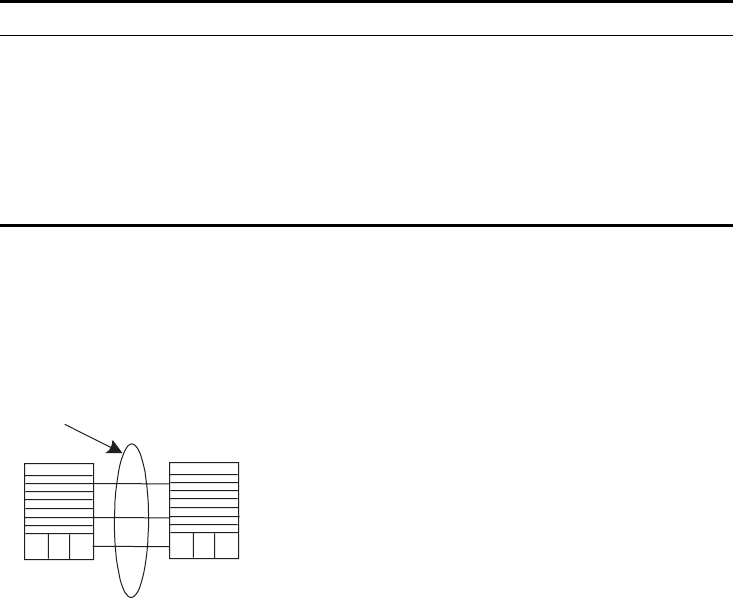
38 CHAPTER 2: PORT CONFIGURATION
Example: Link
Aggregation
Configuration
Switch A connects switch B with three aggregation ports, numbered as
GigabitEthernet2/1/1 to GigabitEthernet2/1/3, so that the incoming and outgoing
loads can be balanced among the member ports.
Figure 2 Networking For Link Aggregation
The following code example lists only the configuration for switch A. The
configuration for switch B is similar.
1Configure aggregation group 1.
[SW8800]link-aggregation group 1 mode manual
Add Ethernet ports GigabitEthernet2/1/1 to GigabitEthernet2/1/3 into
aggregation group 1.
[SW8800]interface gigabitethernet2/1/1
[SW8800-GigabitEthernet2/1/1]port link-aggregation group 1
[SW8800-GigabitEthernet2/1/1]interface ethernet2/1/2
[SW8800-GigabitEthernet2/1/2]port link-aggregation group 1
[SW8800-GigabitEthernet2/1/2]interface ethernet2/1/3
[SW8800-GigabitEthernet2/1/3]port link-aggregation group 1
Display detailed link aggregation information
at the port
display link-aggregation interface {
interface-type interface-number |
interface-name } [ to { interface-type
interface-num | interface-name } ]
Disable/enable debugging link aggregation
errors
[ undo ] debugging link-aggregation error
Disable/enable debugging link aggregation
events
[ undo ] debugging link-aggregation
event
Table 19 Display and Debug Link Aggregation (continued)
Operation Command
Link aggregation
Switch A Switch B

3VLAN CONFIGURATION
This chapter covers the following topics:
■VLAN Overview
■Configuring VLANs
■Configuring GARP/GVRP
VLAN Overview A virtual local area network (VLAN) creates logical groups of LAN devices into
segments to implement virtual workgroups.
Using VLAN technology, you can logically divide the physical LAN into different
broadcast domains. Every VLAN contains a group of workstations with the same
resource requirements. However, the workstations of a VLAN do not have to
belong to the same physical LAN segment.
Within a VLAN, broadcast and unicast traffic is not forwarded to other VLANs.
Therefore, VLAN configurations are very helpful in controlling network traffic,
simplifying network management, and improving security.
The Switch 8800 supports port-based VLANs, which define VLAN members
according to switch ports. This is the simplest and most efficient way to create
VLANs.
Configuring VLANs The following sections describe how to configure VLANs:
■Common VLAN Configuration Tasks
Common VLAN
Configuration Tasks
The following sections discuss the common tasks for configuring a VLAN:
■Creating or Deleting a VLAN
■Adding Ethernet Ports to a VLAN
■Setting or Deleting the VLAN Description Character String
■Specifying or Removing VLAN Interfaces
■Shutting Down or Enabling a VLAN Interface
■Displaying and Debugging a VLAN
Creating or Deleting a VLAN
Use the following command to create or delete a VLAN.

40 CHAPTER 3: VLAN CONFIGURATION
Perform the following configurations in system view.
The command creates the VLAN then enters the VLAN view. If the VLAN already
exists, the command enters the VLAN view directly.
Note that the default VLAN, VLAN 1, cannot be deleted.
Adding Ethernet Ports to
a VLAN
Use the port interface_list command to add the Ethernet ports to a VLAN.
Perform the following configuration in VLAN view.
By default, the system adds all the ports to a default VLAN, whose ID is 1.
You can add or delete trunk port and hybrid ports to or from a VLAN by the port
and undo port commands in Ethernet port view, but not in VLAN view.
Setting or Deleting the VLAN Description Character String
You can use the following command to set or delete the VLAN description
character string.
You can use description character strings, such as workgroup_name and
department_name, to distinguish the different VLANs.
Perform the following configuration in VLAN view.
By default, the VLAN description character string is the VLAN ID of the VLAN,
VLAN 0001. The VLAN interface description character string is the VLAN interface
name, for example, 3Com, Switch 8800, Vlan-interface1 Interface.
Specifying or Removing VLAN Interfaces
You can use the following command to specify or remove the VLAN interfaces. To
implement the network layer function on a VLAN interface, the VLAN interface
should be configured with an IP address and mask. For the corresponding
configuration, refer to “Network Protocol Operation” on page 49.
Tab le 1 Creating or Deleting a VLAN
Operation Command
Create and enter a VLAN view vlan vlan_id
Delete the specified VLAN undo vlan { vlan_id [ to vlan_id ] / all }
Tab le 2 Adding Ethernet Ports to a VLAN
Operation Command
Add Ethernet ports to a VLAN port interface_list
Remove Ethernet ports from a VLAN undo port interface_list
Tab le 3 Setting and Deleting VLAN Description Character String
Operation Command
Set the description character string for the
specified VLAN
description string
Delete the description character string of the
specified VLAN
undo description

Configuring VLANs 41
Perform the following configurations in system view.
Create a VLAN before creating an interface for it.
Shutting Down or Enabling a VLAN Interface
Use the following command to shut down or enable a VLAN interface.
Perform the following configuration in VLAN interface view.
The operation of shutting down or enabling the VLAN interface has no effect on
the UP/DOWN status of the Ethernet ports in the VLAN.
By default, when the status of all Ethernet ports in a VLAN is DOWN, the status of
the VLAN interface is DOWN also so the VLAN interface is shut down. When the
status of one or more Ethernet ports is UP, the status of the VLAN interface is UP
also, so the VLAN interface is enabled.
Displaying and Debugging a VLAN
After the configuring a VLAN, execute the display command in any view to
display the VLAN configuration, and to verify the effect of the configuration.
Example: VLAN
Configuration
Create VLAN2 and VLAN3. Add GigabitEthernet3/1/1 and GigabitEthernet4/1/1 to
VLAN2 and add GigabitEthernet3/1/2 and GigabitEthernet4/1/2 to VLAN3.
Table 4 Specifying and Removing VLAN interfaces
Operation Command
Create a new VLAN interface
and enter VLAN interface view
interface vlan-interface vlan_id
Remove the specified VLAN
interface
undo interface vlan-interface vlan_id
Table 5 Shutting Down or Enabling a VLAN Interface
Operation Command
Shut down the VLAN interface shutdown
Enable the VLAN interface undo shutdown
Table 6 Displaying and Debugging a VLAN
Operation Command
Display the information about a VLAN
interface
display interface vlan-interface [ vlan_id ]
Display the information about a VLAN display vlan [ vlan_id | all | static | dynamic ]
42 CHAPTER 3: VLAN CONFIGURATION
Figure 1 VLAN Configuration Example
1Create VLAN 2 and enter its view.
[SW8800]vlan 2
2Add GigabitEthernet3/1/1 and GigabitEthernet4/1/1 to VLAN2.
[SW8800-vlan2]port GigabitEthernet3/1/1 GigabitEthernet4/1/1
3Create VLAN 3 and enters its view.
[SW8800-vlan2]vlan 3
4Add GigabitEthernet3/1/2 and GigabitEthernet4/1/2 to VLAN3.
[SW8800-vlan3]port GigabitEthernet3/1/2 GigabitEthernet4/1/2
Configuring
GARP/GVRP
Generic Attribute Registration Protocol (GARP), allows members in the same
switching network to distribute, propagate, and register information, such as
VLAN and multicast addresses.
GARP does not exist in a switch as an entity. A GARP participant is called a GARP
application. The main GARP applications are GVRP and GMRP. GVRP is described
in Configuring GARP/GVRP and GMRP is described in “GMRP” on page 203.
When a GARP participant is on a port of the switch, each port corresponds to a
GARP participant.
Through GARP, configuration information on one GARP member is advertised to
the entire switching network. A GARP member can be a terminal workstation or a
bridge. A GARP member can notify other members to register or remove its
Switch 8800
VLAN2 VLAN3
E3/1/1
E4/1/1
E3/1/2
E4/1/2

Configuring GARP/GVRP 43
attribute information by sending join declarations or withdrawal declarations. It
can also register or remove the attribute information of other GARP members
according to the join declarations or withdrawal declarations that it receives from
them.
GARP members exchange information by sending GARP messages. There are three
main types of GARP messages, including join, leave, and leaveall. When a GARP
participant wants to register its attribute information on other switches, it sends a
join message. When the GARP participant wants to remove its attribute
information from other switches, it sends a leave message. The leaveall timer is
started at the same time that each GARP participant is enabled and a leaveall
message is sent out when the leaveall timer times out. The join and leave
messages cooperate to ensure the logout and the re-registration of a message. By
exchanging messages, all the attribute information to be registered can be
propagated to all the switches in the same switching network.
The destination MAC addresses of the packets of the GARP participants are
specific multicast MAC addresses. A switch that supports GARP classifies the
packets that it receives from GARP participants and processes them with the
corresponding GARP applications (GVRP or GMRP).
GARP and GMRP are described in detail in the IEEE 802.1p standard. The Switch
8800 fully supports GARP compliant with the IEEE standards.
■The value of the GARP timer is used in all GARP applications, including GVRP
and GMRP, that are running in a switched network.
■In one switched network, GARP timers on all the switching devices should be
set to the same value.
Setting the GARP Timers
GARP timers include the hold, join, and leaveall timers.
The GARP participant sends join message regularly when the join timer times out
so that other GARP participants can register its attribute values.
When the GARP participant wants to remove attribute values, it sends a leave
message. When the leave message arrives, the receiving GARP participant starts
the leave timer. If the receiving participant does not receive a join message from
the sender before the leave timer expires, the receiving participant removes the
sender’s GARP attribute values.
The leaveall timer is started as soon as a GARP participant joins. A leaveall message
is sent at timeout so that other GARP participants remove all the attribute values
of this participant. Then, the leaveall timer is restarted and a new cycle begins.
When a switch receives GARP registration information, it does not send a join
message immediately. Instead, it enables a hold timer and sends the join message
outward when the hold timer times out. In this way, all the VLAN registration

44 CHAPTER 3: VLAN CONFIGURATION
information received within the time specified by the hold timer can be sent in one
frame to save bandwidth.
The value of the join timer should be no less than twice the value of the hold
timer, and the value of the leave timer should be greater than twice the value of
the join timer and smaller than the leaveall timer value. Otherwise, the system
displays an error message.
Join timer > 2 x hold timer > leave timer < leavall timer
GARP timers have the following default values:
■Hold timer — 10 centiseconds
■Join timer — 20 centiseconds,
■Leave timer — 60 centiseconds
■Leaveall timer — 1000 centiseconds.
Displaying and Debugging GARP
After you configure the GARP timer, use the display command in all views to
display the GARP configuration, and to verify the effect of the configuration.
Execute the reset command in user view to reset the GARP configuration.
Execute the debugging command in user view to debug the GARP configuration.
Configuring GVRP GARP VLAN Registration Protocol (GVRP) is a GARP application. GVRP is based on
the GARP, and maintains the dynamic VLAN registration information in the switch
and distributes the information to other switches. All the GVRP-supporting
switches can receive VLAN registration information from other switches and can
Tab le 7 Setting the GARP Timers
Operation Command
Configure the hold, join, and leave timers in Ethernet port view.
Set the GARP hold, join, and leave
timers
garp timer { hold | join | leave } timer_value
Restore the default GARP hold,
join, and leave timer settings
undo garp timer { hold | join | leave }
Configure the leaveall timer in system view.
Set GARP leaveall timer garp timer leaveall timer_value
Restore the default GARP leaveall
timer settings.
undo garp timer leaveall
Tab le 8 Display and Debug GARP
Operation Command
Display GARP statistics information display garp statistics [ interface interface-list ]
Display GARP timer display garp timer [ interface interface-list ]
Reset GARP statistics information reset garp statistics [ interface interface-list ]
Enable GARP event debugging debugging garp event
Disable GARP event debugging undo debugging garp event

Configuring GARP/GVRP 45
dynamically update local VLAN registration information, including the active
members and the port through which each member can be reached.
All the switches that support GVRP can distribute their local VLAN registration
information to other switches so that VLAN information is consistent on all GVRP
devices in the same network. The VLAN registration information that is distributed
by GVRP includes both the local static registration information that is configured
manually and the dynamic registration information received from other switches.
GVRP is described in the IEEE 802.1Q standard. The Switch 8800 fully supports
GARP compliant with the IEEE standards.
GVRP configuration steps include tasks described in the following sections:
■Enabling or Disabling Global GVRP
■Enabling or Disabling Port GVRP
■Setting the GVRP Registration Type
When you configure GVRP, you need to enable it globally and for each port
participating in GVRP. Similarly, the GVRP registration type can take effect only
after you configure port GVRP. In addition, you must configure GVRP on the trunk
port.
Enabling or Disabling Global GVRP
Use the following commands to enable or disable global GVRP.
Perform the following configurations in system view.
By default, GVRP is disabled on a port.
Enabling or Disabling Port GVRP
Use the following commands to enable or disable GVRP on a port.
Perform the following configurations in Ethernet port view.
You should enable GVRP globally before you enable it on the port. GVRP can only
be enabled or disabled on a trunk port.
By default, global GVRP is disabled.
Table 9 Enabling/Disabling Global GVRP
Operation Command
Enable global GVRP gvrp
Disable global GVRP undo gvrp
Table 10 Enabling/Disabling Port GVRP
Operation Command
Enable port GVRP gvrp
Disable port GVRP undo gvrp

46 CHAPTER 3: VLAN CONFIGURATION
Setting the GVRP Registration Type
The GVRP includes normal, fixed, and forbidden registration types (see IEEE
802.1Q).
■When an Ethernet port registration type is set to normal, the dynamic and
manual creation, registration, and logout of VLAN are allowed on this port.
■When one trunk port registration type is set to fixed, the system adds the port
to the VLAN if a static VLAN is created on the switch and the trunk port allows
VLAN passing. GVRP also adds this VLAN item to the local GVRP database, one
link table for GVRP maintenance. However, GVRP cannot learn dynamic VLAN
through this port.
■When an Ethernet port registration type is set to forbidden, all the VLANs
except VLAN1 are removed and no other VLANs can be created or registered
on this port.
Perform the following configurations in Ethernet port view.
By default, the GVRP registration type is normal.
Displaying and Debugging GVRP
After you set the GVRP registration type, execute the display command in all
views to display the GVRP configuration and to verify the effect of the
configuration.
Execute the debugging command in user view to debug the configuration of
GVRP.
Example: GVRP
Configuration Example
Set network requirements to dynamically register and update VLAN information
among switches.
Tab le 11 Setting the GVRP Registration Type
Operation Command
Set GVRP registration type gvrp registration { normal | fixed | forbidden }
Set the GVRP registration type back
to the default setting
undo gvrp registration
Tab le 12 Displaying and Debugging GVRP
Operation Command
Display GVRP statistics information display gvrp statistics [ interface interface-list ]
Display GVRP global status
information
display gvrp status
Enable GVRP packet or event
debugging
debugging gvrp { packet | event}
Disable GVRP packet or event
debugging
undo debugging gvrp { packet | event}
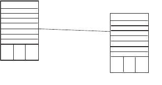
Configuring GARP/GVRP 47
Figure 2 GVRP Configuration Example
Configure Switch A:
1Set GigabitEthernet3/1/1 as a trunk port and allow all the VLANs to pass through.
[SW8800]interface GigabitEthernet3/1/1
[SW8800-GigabitEthernet3/1/1]port link-type trunk
[SW8800-GigabitEthernet3/1/1]port trunk permit vlan all
2Enable GVRP on the trunk port.
[SW8800-GigabitEthernet3/1/1]gvrp
Configure Switch B:
1Enable GVRP globally.
[SW8800]gvrp
2Set Gigabit Ethernet4/1/1 as a trunk port and allow all the VLANs to pass
through.
[SW8800]interface GigabitEthernet4/1/1
[SW8800-GigabitEthernet4/1/1]port link-type trunk
[SW8800-GigabitEthernet4/1/1]port trunk permit vlan all
3Enable GVRP on the trunk port.
[SW8800-GigabitEthernet4/1/1]gvrp
Switch A
E3/1/1
Switch B
E4/1/1
48 CHAPTER 3: VLAN CONFIGURATION

4NETWORK PROTOCOL OPERATION
This chapter covers the following topics:
■Configuring IP Address
■Configuring Address Resolution Protocol (ARP)
■DHCP Relay
■IP Performance
Configuring IP
Address
IP address is a 32-bit address represented by four octets. IP addresses are divided
into five classes, A, B, C, D and E. The octets are set according to the first few bits
of the first octet.
The rule for IP address classification is described as follows:
■Class A addresses are identified with the first bit of the first octet being 0.
■Class B addresses are identified with the first bits of the first octet being 10.
■Class C addresses are identified with the first bits of the first octet being 110.
■Class D addresses are identified with the first bits of the first octet being 1110.
■Class E addresses are identified with the first bits of the first octet being 11110.
Addresses of Classes A, B and C are unicast addresses. The Class D addresses are
multicast addresses and Class E addresses are reserved for future uses.
At present, IP addresses are mostly Class A, Class B and Class C. IP addresses of
Classes A, B and C are composed of two parts, network ID and host ID. Their
network ID lengths are different.
■Class A IP addresses use only the first octet to indicate the network ID.
■Class B IP addresses use the first two octets to indicate the network ID.
■Class C IP addresses use the first three octets to indicate the network ID.
At most, there are: 28 =128 Class A addresses, 216=16384 Class B addresses and
224=2,097,152 Class C addresses.
The IP address is in dotted decimal format. Each IP address contains 4 integers in
dotted decimal notation. Each integer corresponds to one byte,
e.g.,10.110.50.101.
Configuring an IP Address is described in the following sections:
■Subnet and Mask
■Configuring an IP Address

50 CHAPTER 4: NETWORK PROTOCOL OPERATION
■Troubleshooting an IP Address Configuration
Subnet and Mask IP protocol allocates one IP address for each network interface. Multiple IP
addresses can only be allocated to a device which has multiple network interfaces.
IP addresses on a device with multiple interfaces have no relationship among
themselves.
With the rapid development of the Internet, IP addresses are depleting very fast.
The traditional IP address allocation method uses up IP addresses with little
efficiency. The concept of mask and subnet was proposed to make full use of the
available IP addresses.
A mask is a 32-bit number corresponding to an IP address. The number consists of
1s and 0s. Principally, these 1s and 0s can be combined randomly. However, the
first consecutive bits are set to 1s when designing the mask. The mask is divided
into two parts, the subnet address and host address. The 1 bits and the mask
indicate the subnet address, and the other bits indicate the host address.
If there is no sub-net division, then the sub-net mask is the default value and the
length of “1” indicates the net-id length. Therefore, for IP addresses of classes A,
B and C, the default values of the corresponding sub-net mask is 255.0.0.0 for
Class A, 255.255.0.0 for Class B, and 255.255.255.0 for Class C.
The mask can be used to divide a Class A network containing more than
16,000,000 hosts or a Class B network containing more than 60,000 hosts into
multiple small networks. Each small network is called a subnet. For example, for
the Class A network address 10.110.0.0, the mask 255.255.224.0 can be used to
divide the network into 8 subnets: (10.110.0.0, 10.110.32.0, 10.110.64.0, and so
on). Each subnet can contain more than 8000 hosts.
Configuring an IP
Address
The following sections describe the tasks for configuring an IP address:
■Configure the Host IP Address and HostName for a Host
■Configuring the IP Address of the VLAN Interface
■Displaying and Debugging an IP Address
Configure the Host IP Address and HostName for a Host
This command creates correspondence between the name and the IP address of
the host. When you use applications like Telnet, you can use the host name
without having to memorize the IP address because the system translates the
name to the IP address automatically.
Perform the following configuration in System view.
By default, there is no host name associated to any host IP address.
Tab le 1 Configure the Host Name and the Corresponding IP Address
Operation Command
Configure the host name and the
corresponding IP address
ip host hostname ip-address
Delete the host name and the corresponding
IP address
undo ip host hostname [ ip-address ]
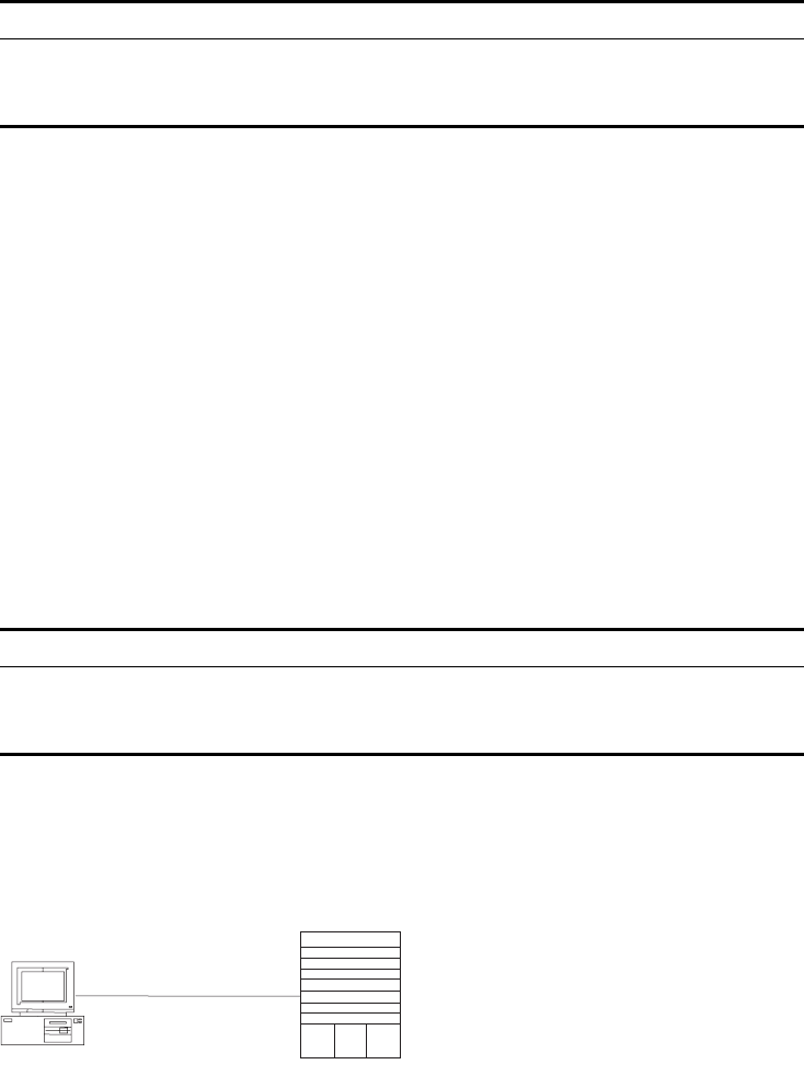
Configuring IP Address 51
Configuring the IP Address of the VLAN Interface
You can configure a maximum of ten IP addresses for a VLAN interface.
Perform the following configuration in VLAN interface view.
The network ID of an IP address is identified by the mask. For example, the IP
address of a VLAN interface is 129.9.30.42 and the mask is 255.255.0.0. After
performing the AND operation for the IP address and the mask, you can assign
that device to the network segment 129.9.0.0.
Generally, it is sufficient to configure one IP address for an interface. However, you
can also configure more than one IP address for an interface so that it can be
connected to several subnets. Among these IP addresses, one is the primary IP
address and all others are secondary.
By default, the IP address of a VLAN interface is null.
Displaying and Debugging an IP Address
Use the display command in all views to display the IP address configuration on
interfaces, and to verify configuration.
Example: Configuring
an IP Address
Configure the IP address as 129.2.2.1 and sub-net mask as 255.255.255.0 for the
VLAN interface 1 of the Switch 8800.
Figure 1 IP Address Configuration Networking
1Enter VLAN interface 1.
[SW8800]interface vlan 1
2Configure the IP address for VLAN interface 1.
[SW8800-vlan-interface1]ip address 129.2.2.1 255.255.255.0
Table 2 Configure IP Address for a VLAN Interface
Operation Command
Configure IP address for a VLAN interface ip address ip-address net-mask [ sub ]
Delete the IP address of a VLAN interface [ undo ] ip address [ ip-address { net-mask |
mask-length } [ sub ] ]
Table 3 Display and Debug IP Address
Operation Command
Display all hosts on the network and the
corresponding IP addresses
display ip hosts
Display the configurations of each interface display ip interface vlan-interface vlan-id
PC
Console cable
Switch

52 CHAPTER 4: NETWORK PROTOCOL OPERATION
Troubleshooting an IP
Address Configuration
If the Switch 8800 cannot ping a certain host on the LAN, proceed as follows:
1Determine which VLAN includes the port connected to the host. Check whether
the VLAN has been configured with the VLAN interface. Determine whether the IP
address of the VLAN interface and the host are on the same network segment.
2If the configuration is correct, enable ARP debugging on the switch from user
level, and check whether or not the switch can correctly send and receive ARP
packets. If it can only send but not receive the ARP packets, there are probably
errors at the Ethernet physical layer.
Configuring Address
Resolution Protocol
(ARP)
An IP address cannot be directly used for communication between network
devices, because devices can only identify MAC addresses. An IP address is the
address of a host at the network layer. To send data packets through the network
layer to the destination host, the physical address of the host is required. So the IP
address must be resolved to a physical address.
When two hosts in Ethernet communicate, they must know each other’s MAC
address. Every host maintains an IP-MAC address translation table, which is known
as the ARP mapping table. A series of maps between IP addresses and MAC
addresses of other hosts are stored in the ARP mapping table. When a dynamic
ARP mapping entry is not in use for a long time, the host will remove it from the
mapping table to save memory space and shorten the search interval.
Example: IP Address
Resolution
Host A and Host B are on the same network segment. The IP address of Host A is
IP_A and the IP address of Host B is IP_B. Host A wants to transmit packets to Host
B. Host A checks its own ARP mapping table first to make sure that there are
corresponding ARP entries of IP_B in the table. If the corresponding MAC address
is found, Host A will use the MAC address in the ARP mapping table to
encapsulate the IP packet in an Ethernet frame and send it to Host B. If the
corresponding MAC address is not found, Host A will store the IP packet in the
queue waiting for transmission, and broadcast an ARP request to attempt to
resolve the MAX address of Host B.
The ARP request packet contains the IP address of Host B and the IP address and
MAC address of Host A. Since the ARP request packet is broadcast, all hosts on
the network segment receive the request. However, only the requested host (i.e.,
Host B) needs to process the request. Host B will first store the IP address and the
MAC address of the request sender (Host A) from the ARP request packet in its
own ARP mapping table. Host B will then generate an ARP reply packet and add
the MAC address of Host B before sending it to Host A. The reply packet will be
sent directly to Host A instead of being broadcast. Upon receiving the reply
packet, Host A will extract the IP address and the corresponding MAC address of
Host B and add them to its own ARP mapping table. Then Host A will send Host B
all the packets standing in the queue.
Normally, dynamic ARP executes and automatically attempts to resolve the IP
address to an Ethernet MAC address with no intervention from the administrator.
Configuring ARP The ARP mapping table can be maintained dynamically or manually. Addresses
that are mapped manually are referred to as static ARP. The user can display, add,
or delete the entries in the ARP mapping table through manual commands.

Configuring Address Resolution Protocol (ARP) 53
ARP configuration includes tasks described in the following sections:
■Manually Adding/Deleting Static ARP Mapping Entries
■Learning Gratuitous ARPs
■Configuring the Dynamic ARP Aging Timer
■Displaying and Debugging ARP
Manually Adding/Deleting Static ARP Mapping Entries
Perform the following configuration in System view.
Static ARP mapping entries will not time out, however dynamic ARP mapping
entries time out after 20 minutes.
The ARP mapping table is empty and the address mapping is obtained through
dynamic ARP by default.
Learning Gratuitous ARPs
Perform the following configuration in System view.
By default, the switch does not learn gratuitous ARPs.
Configuring the Dynamic ARP Aging Timer
The following commands assign a dynamic ARP aging period to enable flexible
configurations. When the system learns a dynamic ARP entry, its aging period is
based on the currently configured value.
Perform the following configuration in system view.
By default, the aging time of the dynamic ARP aging timer is 20 minutes.
Displaying and Debugging ARP
After the previous configuration, execute display command in all views to display
the operation of the ARP configuration, and to verify the effect of the
Table 4 Manually Adding/Deleting Static ARP Mapping Entries
Operation Command
Manually add a static ARP mapping entry arp static ip-address mac-address VLANID {
interface_type interface_num | interface_name
}
Manually delete a static ARP mapping entry undo arp static ip-address
Table 5 Learning Gratuitous ARPs
Operation Command
Enable the switch to learn gratuitous ARPs gratuitous-arp-learning enable
Prevent the switch from learning gratuitous
ARPs
undo gratuitous-arp-learning enable
Table 6 Configure the Dynamic ARP Aging Timer
Operation Command
Configure the dynamic ARP aging timer arp timer aging aging-time
Restore the default dynamic ARP aging time undo arp timer aging
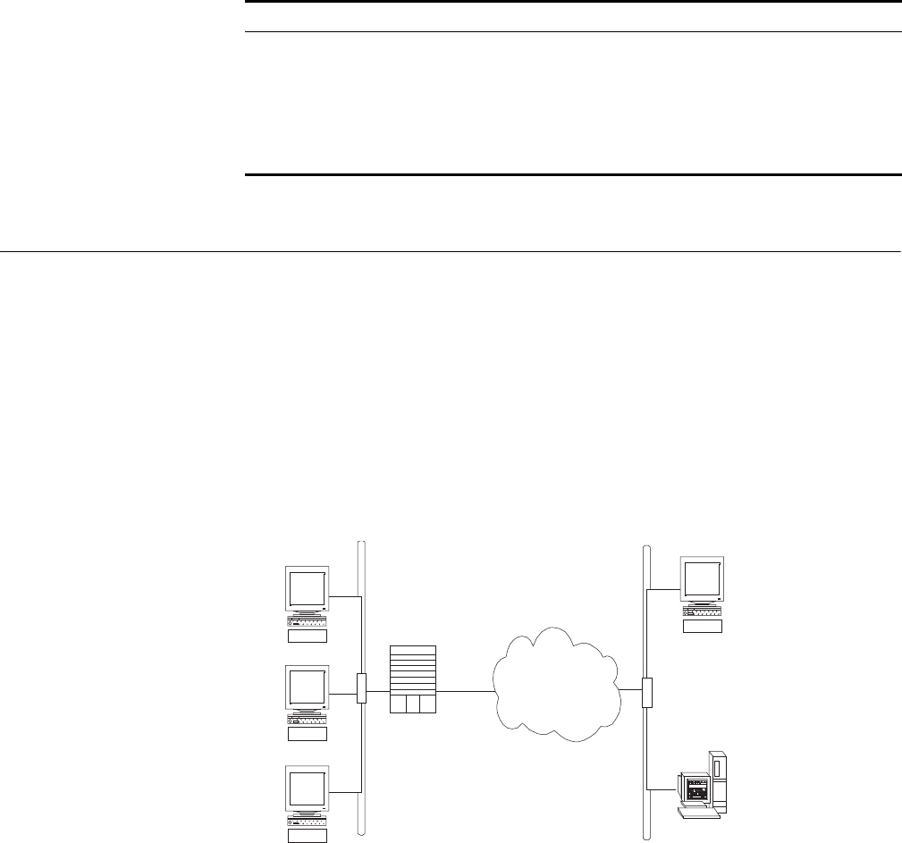
54 CHAPTER 4: NETWORK PROTOCOL OPERATION
configuration. Execute the debugging command in user view to debug the ARP
configuration.
By default, all ARP mapping entries of the Ethernet switch are displayed.
DHCP Relay Dynamic Host Configuration Protocol (DHCP) offers dynamic IP address
assignment. DHCP works in Client-Server mode. With this protocol, the DHCP
Client can dynamically request configuration information and the DHCP server can
configure the information for the Client.
The DHCP relay serves as conduit between the DHCP Client and the server located
on different subnets. The DHCP packets can be relayed to the destination DHCP
server (or Client) across network segments. The DHCP clients on different
networks can use the same DHCP server. This is economical and convenient for
centralized management.
Figure 2 DHCP Relay Schematic Diagram
When the DHCP Client performs initialization, it broadcasts the request packet on
the local network segment. If there is a DHCP server on the local network segment
(e.g. the Ethernet on the right side of the figure), then the DHCP can be
configured directly without the relay. If there is no DHCP server on the local
network segment, DHCP relay will process the received broadcast packets and
forward them to remote DHCP servers. The server configures the clients based on
the information provided in the DHCP request packet and in the server setup.
Then the server transmits the configuration information to the clients through the
DHCP relay, thereby, completing the dynamic configuration of the client.
Tab le 7 Display and Debug ARP
Operation Command
Display ARP mapping table display arp [ ip-address | [ static | dynamic ] [
{ begin | include | exclude } text ] ]
Display the current setting of the dynamic
ARP map aging timer
display arp timer aging
Enable ARP information debugging debugging arp { error | info | packet }
Disable ARP information debugging undo debugging arp { error | info | packet }
DHCP clients
DHCP clients
Switch
Switch
Intranet
Intranet
DHCP client
DHCP client
DHCP server
DHCP server
Ethernet
Ethernet
Ethernet
Ethernet
DHCP Relay 55
Configuring DHCP is described in the following sections:
■Configuring DHCP Relay
■Troubleshooting a DHCP Relay Configuration
Configuring DHCP Relay DHCP relay configuration includes tasks described in the following sections:
■Configuring a DHCP Server IP Address in a DHCP Server Group
■Configuring the DHCP Server Group for the VLAN Interface
■Configuring the Address Table Entry
■Enabling/Disabling DHCP Security Features
■Enabling/Disabling DHCP Pseudo-server Detection
■Displaying and Debugging DHCP Relay
The server IP address is associated , through its DHCP server group, with a specific
VLAN interface. This implementation differs from others in which the server IP is a
global parameter.
Configuring a DHCP Server IP Address in a DHCP Server Group
You can set master and slave DHCP servers on a network segment to promote the
reliability of the device. The master and slave DHCP servers form a DHCP server
group. You can specify the IP addresses of the two servers using the following
command.
Perform the following configuration in System view.
The backup server IP address cannot be configured independently, instead, it has
to be configured together with the master server IP address.
By default, the IP address of the DHCP Server is not configured. The DHCP Server
address must be configured before DHCP relay can be used.
Configuring the DHCP Server Group for the VLAN Interface
Perform the following configuration in VLAN interface view.
Table 8 Configure/Delete the IP Address of the DHCP Server
Operation Command
Configure the IP address for a DHCP Server dhcp-server groupNo ip ipaddress1 [
ipaddress2 ]
Remove all the IP addresses of the DHCP
Server (set the IP addresses of the primary and
secondary servers to 0).
undo dhcp-server groupNo
Table 9 Configure/Delete the Corresponding DHCP Server Group of VLAN Interface
Operation Command
Configure the DHCP server group for the
VLAN interface
dhcp-server groupNo
Delete the DHCP server group for the VLAN
interface
undo dhcp-server

56 CHAPTER 4: NETWORK PROTOCOL OPERATION
When associating a VLAN interface to a new DHCP server group, you can
configure the association without disassociating it from the previous group.
By default, VLAN interfaces have no associated DHCP server group.
Configuring the Address Table Entry
To check the address of users who have valid and fixed IP addresses in the VLAN
(with DHCP enabled), it is necessary to add an entry in the static address table.
Perform the following configuration in system view.
Enabling/Disabling DHCP Security Features
Enabling DHCP security features starts an address check on the VLAN interface,
while disabling DHCP security features cancels an address check.
Perform the following configuration in VLAN interface view.
By default, DHCP security features function are disabled.
Enabling/Disabling DHCP Pseudo-server Detection
Suppose there is a DHCP server placed on a network without permission. When
there is a user request for an IP address, the DHCP server will interact with the
DHCP client, leading the user to get a wrong IP address. In this case, the user will
be unable to access the network. Such a DHCP server is called DHCP
pseudo-server.
After a DHCP pseudo-server detection-enabled, switch will record the information
of the DHCP servers such as their IP addresses so that the administrator can
discover the DHCP pseudo-servers.
Perform the following configuration in system view.
By default, DHCP pseudo-server detection is disabled.
Tab le 10 Configure/Delete the Address Table Entry
Operation Command
Add an entry to the address table dhcp-security static ip_address mac_address
{ dynamic | static }
Delete an entry from the address table undo dhcp-security { ip_address | all |
dynamic | static }
Tab le 11 Enable/Disable DHCP Security on VLAN Interfaces
Operation Command
Enable DHCP security features address-check enable
Disable DHCP security features on VLAN
interface
address-check disable
Tab le 12 Enabling and Disabling DHCP Pseudo-server Detection
Operation Command
Enable DHCP pseudo-server detection dhcp-server detect
Disable DHCP pseudo-server detection undo dhcp-server detect
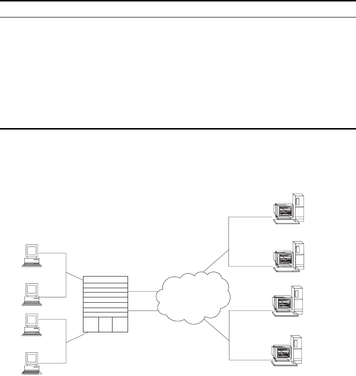
DHCP Relay 57
Displaying and Debugging DHCP Relay
Execute display command in all views to display the current DHCP Relay
configuration, and to verify the effect of the configuration. Execute the
debugging command in user view to debug DHCP Relay configuration.
Example: Configuring
DHCP Relay
Configure the VLAN interface corresponding to the user and the related DHCP
server so as to use DHCP relay.
Figure 3 Networking Diagram of Configuring DHCP Relay
1Configure the DHCP Server IP addresses into DHCP Server Group 1.
[SW8800]dhcp-server 1 ip 1.99.255.36 1.99.255.35
2Associate DHCP Server Group 1 with VLAN interface 2.
[SW8800-VLAN-Interface2]dhcp-server 1
3Configure the IP address corresponding to DHCP server group 2.
[SW8800]dhcp-server 2 ip 1.88.255.36 1.88.255.35
4Associate the DHCP Server Group 2 with VLAN interface 3.
[SW8800-VLAN-Interface3]dhcp-server 2
5Configure the corresponding interface and gateway address of VLAN2.
[SW8800]vlan 2
[SW8800-vlan2]port GigabitEthernet 1/1/2
[SW8800]interface vlan 2
[SW8800-VLAN-Interface2]ip address 1.1.2.1 255.255.0.0
Table 13 Displaying and Debugging DHCP Relay
Operation Command
Display the information about the DHCP
server group
display dhcp-server groupNo
Display the information about the DHCP
server group corresponding to the VLAN
interface.
display dhcp-server interface
vlan-interface vlan-id
Enable DHCP relay debugging debugging dhcp-relay
Disable DHCP relay debugging undo debugging dhcp-relay
Display address information for all the legal
clients of the DHCP Server group.
display dhcp-security [ ip_address |
dynamic | static ]
VLAN 2
VLAN 3
VLAN
4000
VLAN
3001
Server Group 1
Server Group 2
1.99.255.36
1.99.255.35
1.88.255.36
1.88.255.35
IP Network
Switch
58 CHAPTER 4: NETWORK PROTOCOL OPERATION
6Configure the corresponding interface and gateway address of VLAN3.
[SW8800]vlan 3
[SW8800-vlan3]port GigabitEthernet 1/1/3
[SW8800]interface vlan 3
[SW8800-VLAN-Interface3]ip address 21.2.2.1 255.255.0.0
7It is necessary to configure a VLAN for the servers. The corresponding interface
VLAN of the DHCP server group 1 is configured as 4000, and that of the group 2
is configured as 3001.
[SW8800]vlan 4000
[SW8800-vlan4000]port GigabitEthernet 1/1/4
[SW8800]interface vlan 4000
[SW8800-VLAN-Interface4000]ip address 1.99.255.1 255.255.0.0
[SW8800]vlan 3001
[SW8800-vlan3001]port GigabitEthernet 1/1/5
[SW8800]interface vlan 3001
[SW8800-VLAN-Interface3001]ip address 1.88.255.1 255.255.0.0
In this example, clients on VLAN2 will receive IP addresses from the servers in
DHCP server group 1 (VLAN 4000). Clients on VLAN3 will receive IP addresses
from the servers in DHCP server group 2 (VLAN 3001).
8Show the configuration of DHCP server groups in User view.
<SW8800>display dhcp-server 1
9Show the DHCP Server Group number corresponding to the VLAN interface in
User view.
<SW8800>display dhcp-server interface vlan-interface 2
<SW8800>display dhcp-server interface vlan-interface 3
Troubleshooting a DHCP
Relay Configuration
Perform the following procedure if a user cannot apply for an IP address
dynamically:
1Use the display dhcp-server groupNo command to check if the IP address of the
corresponding DHCP server has been configured.
2Use the display VLAN and display IP commands to check if the VLAN and the
corresponding interface IP address have been configured.
3Ping the configured DHCP Server to ensure that the link is connected.
4Ping the IP address of the VLAN interface of the switch to where the DHCP user is
connected from the DHCP server to make sure that the DHCP server can correctly
find the route of the network segment the user is on. If the ping execution fails,
check if the default gateway of the DHCP server has been configured as the
address of the VLAN interface that it locates on.
5If no problems are found in the last two steps, use the display dhcp-server
groupNo command to view the packet that has been received. If you only see the
Discover packet and there is no response packet, it means the DHCP Server has
not sent the message to the Switch 8800. In this case, check if the DHCP Server
has been configured properly. If the numbers of request and response packets are
normal, enable the debugging dhcp-relay in User view and then use the terminal
debugging command to output the debugging information to the console. In
this way, you can view the detailed information of all DHCP packets on the
console while applying for the IP address, thereby, conveniently locating the
problem.

IP Performance 59
IP Performance IP performance configuration includes:
■Configuring TCP Attributes
■Displaying and Debugging IP Performance
■Troubleshooting IP Performance
Configuring TCP
Attributes
The TCP attributes that can be configured include:
■synwait timer: When sending the syn packets, TCP starts the synwait timer. If
response packets are not received before synwait timeout, the TCP connection
will be terminated. The timeout of synwait timer ranges 2 to 600 seconds and
it is 75 seconds by default.
■finwait timer: When the TCP connection state turns from FIN_WAIT_1 to
FIN_WAIT_2, finwait timer will be started. If FIN packets are not received before
finwait timer timeout, the TCP connection will be terminated. Finwait ranges
76 to 3600 seconds and it is 675 seconds by default.
■The receiving/sending buffer size of connection-oriented Socket is in the range
from 1 to 32K bytes and is 4K bytes by default.
Perform the following configuration in System view.
By default, the TCP finwait timer is 675 seconds, the synwait timer is 75 seconds,
and the receiving/sending buffer size of connection-oriented Socket is 4K bytes.
Displaying and
Debugging IP
Performance
After the previous configuration, display the operation of the IP Performance
configuration in all views, and verify the effect of the configuration. Execute the
debugging command in user view to debug IP Performance configuration.
Table 14 Configure TCP Attributes
Operation Command
Configure synwait timer time for TCP
connection establishment
tcp timer syn-timeout time-value
Restore synwait timer time for TCP connection
establishment to default value
undo tcp timer syn-timeout
Configure FIN_WAIT_2 timer time of TCP tcp timer fin-timeout time-value
Restore FIN_WAIT_2 timer time of TCP to
default value
undo tcp timer fin-timeout
Configure the Socket receiving/sending buffer
size of TCP
tcp window window-size
Restore the socket receiving/sending buffer
size of TCP to default value
undo tcp window
Table 15 Display and Debug IP Performance
Operation Command
Display TCP connection state display tcp status
Display TCP connection statistics data display tcp statistics
Display IP statistics information display ip statistics
Display ICMP statistics information display icmp statistics
Display the summary of the FIB display fib

60 CHAPTER 4: NETWORK PROTOCOL OPERATION
Troubleshooting IP
Performance
If the IP layer protocol works normally, but TCP and UDP do not work normally,
you can enable the corresponding debugging information output to view the
debugging information.
■Use the terminal debugging command to output the debugging information
to the console.
■Use the debugging udp packet command to enable the UDP debugging to
trace the UDP packet. When the router sends or receives UDP packets, the
content format of the packet can be displayed in real time. You can locate the
problem from the contents of the packet.
The following are the UDP packet formats:
UDP output packet:
Source IP address:202.38.160.1
Source port:1024
Destination IP Address 202.38.160.1
Destination port: 4296
■Use the debugging tcp packet or debugging tcp transaction command to
enable the TCP debugging to trace the TCP packets. There are two available
ways for debugging TCP.
■Debug and trace the packets of the TCP connection that take this device as one
end.
Operations include:
<SW8800>terminal debugging
<SW8800>debugging tcp packet
The TCP packets, received or sent can be checked in real time. Specific packet
formats include:
TCP output packet:
Source IP address:202.38.160.1
Source port:1024
Destination IP Address 202.38.160.1
Destination port: 4296
Sequence number :4185089
Ack number: 0
Flag :SYN
Display the FIB entries matching the
destination IP address (range)
display fib ip_address1 [ { mask1 |
mask-length1 } [ ip_address2 { mask2 |
mask-length2 } | longer ] | longer ]
Display the FIB entries that match a specific
ACL
display fib acl { number | name }
Display the FIB entries which are output from
the buffer according to regular expression and
related to the specific character string
display fib | { { begin | include | exclude }
text }
Display the FIB entries matching the specific
prefix list
display fib ip-prefix listname
Display the total number of FIB entries display fib statistics
Reset IP statistics information reset ip statistics
Reset TCP statistics information reset tcp statistics
Table 15 Display and Debug IP Performance
Operation Command

IPX Configuration 61
Packet length :60
Data offset: 10
■Debug and trace the packets located in SYN, FIN or RST.
Operations include:
<SW8800>terminal debugging
<SW8800>debugging tcp transact
The TCP packets received or sent can be checked in real time, and the specific
packet formats are the same as those mentioned above.
IPX Configuration Internetwork Packet Exchange (IPX) protocol is a network layer protocol in the
NetWare protocol suite. It is similar to IP in the TCP/IP protocol suite. IPX functions
to address, route and forward packets.
IPX is a connectionless protocol. Though an IPX packet includes a destination IPX
address in addition to the data, there is no guarantee of successful delivery. Packet
acknowledgement and connection control must be provided by protocols above
IPX. Each IPX packet is considered an independent entity that has no logical or
sequential relationship with any other IPX packets.
IPX Address Structure IPX and IP use different address structures. An IPX address comprises two parts:
the network number and the node address; it is in the format of network.node.
A network number identifies the network where a site is located. It is four bytes
long and expressed by eight hexadecimal numbers. A node address identifies a
node on the network. Like a MAC address, it is six bytes long and written with the
bytes being separated into three 2-byte parts by “-”. The node address cannot be
a broadcast or multicast address. For example, in the IPX address bc.0-0cb-47, bc
(or 000000bc) is the network number and 0-0cb-47 (0000-00cb-0047) is the node
address. You can also write an IPX address in the form of N.H-H-H, where N is the
network number and H-H-H is the node address.
Routing Information
Protocol
IPX uses the Routing Information Protocol (RIP) to maintain and advertise dynamic
routing information. With IPX enabled, the switch exchanges routing information
with other neighbors through RIP to maintain an internetwork routing information
database (also known as a routing table) to accommodate to the network
changes. When the switch receives a packet, it looks up the routing table for the
next site and if there is any, forwards the packet. The routing information can be
configured statically or collected dynamically.
This chapter introduces RIP in IPX. For the RIP configurations on an IP network,
refer to the routing protocol section in this manual.
Service Advertising
Protocol
The Service Advertising Protocol (SAP) advertises the services provided by servers
and their addresses. It is used by IPX to maintain and advertise dynamic service
information. With SAP, a server broadcasts its services when it starts and the
termination of the services when it goes down.
With IPX enabled, the switch creates and maintains an internetwork service
information database (or the service information table) through SAP. It helps you
learn what services are available on the networks and where they are provided.
62 CHAPTER 4: NETWORK PROTOCOL OPERATION
The servers periodically broadcast their services and addresses to the networks
directly connected to them. Users cannot use such information directly, however.
Instead, the information is collected by the SAP agents of the switches on the
networks and saved in their server information tables.

5IP ROUTING PROTOCOL OPERATION
This chapter covers the following topics:
■IP Routing Protocol Overview
■Static Routes
■RIP
■OSPF
■IS-IS
■BGP
■IP Routing Policy
■Route Capacity
IP Routing Protocol
Overview
Routers select an appropriate path through a network for an IP packet according
to the destination address of the packet. Each router on the path receives the
packet and forwards it to the next router. The last router in the path submits the
packet to the destination host.
In a network, the router regards a path for sending a packet as a logical route unit,
and calls it a hop. For example, in Figure 1, a packet sent from Host A to Host C
goes through 3 networks and 2 routers and the packet is transmitted through two
hops and router segments. Therefore, when a node is connected to another node
through a network, there is a hop between these two nodes and these two nodes
are considered adjacent in the Internet. Adjacent routers are two routers
connected to the same network. The number of route segments between a router
and hosts in the same network count as zero. In Figure 1, the bold arrows
represent the hops. A router can be connected to any physical link that constitutes
a route segment for routing packets through the network.
When a switch runs a routing protocol, it can perform router functions. In this
guide, a router and its icon represent a generic router or a switch running routing
protocols.
64 CHAPTER 5: IP ROUTING PROTOCOL OPERATION
Figure 1 About Hops
Networks can have different sizes, so, the segment lengths connected between
two different pairs of routers are also different.
If a router in a network is regarded as a node and a route segment in the Internet
is regarded as a link, message routing in the Internet works in a similar way as the
message routing in a conventional network. Routing a message through the
shortest route may not always be the optimal route. For example, routing through
three LAN route segments may be much faster than a route through two WAN
route segments.
Configuring the IP Routing Protocol Overview is described in the following
sections:
■Selecting Routes Through the Routing Table
■Routing Management Policy
Selecting Routes
Through the Routing
Table
For the router, a routing table is the key to forwarding packets. Each router saves a
routing table in its memory, and each entry in this table specifies the physical port
of the router through which a packet is sent to a subnet or a host. The packet can
reach the next router over a particular path or reach a destination host through a
directly connected network.
A routing table has the following key entries:
■A destination address — Identifies the destination IP address or the destination
network of the IP packet, which is 32 bits in length.
■A network mask — Is made up of several consecutive 1s, which can be
expressed either in the dotted decimal format, or by the number of the
consecutive 1s in the mask. Combined with the destination address, the
network mask identifies the network address of the destination host or router.
With the destination address and the network mask, you have the address of
the network segment where the destination host or router is located. For
example, if the destination address is 129.102.8.10, the address of the
network where the host or the router with the mask 255.255.0.0 is located is
129.102.0.0.
Route
Segment
A
C
R
R
R
R
R
B
IP Routing Protocol Overview 65
■The output interface — Indicates an interface through which an IP packet
should be forwarded.
■The next hop address — Indicates the next router that an IP packet will pass
through.
■The priority added to the IP routing table for a route — Indicates the type of
route that is selected. There may be multiple routes with different next hops to
the same destination. These routes can be discovered by different routing
protocols, or they can be the static routes that are configured manually. The
route with the highest priority (the smallest numerical value) is selected as the
current optimal route.
Types of routes are divided into the following types, subnet routes, in which the
destination is a subnet, or host routes, in which the destination is a host.
In addition, depending on whether the network of the destination host is directly
connected to the router, there are the following types of routes:
■Direct route: The router is directly connected to the network where the
destination is located.
■Indirect route: The router is not directly connected to the network where the
destination is located.
To limit the size of the routing table, an option is available to set a default route.
All the packets that fail to find a suitable table entry are forwarded through this
default route.
In a complicated Internet, as shown in the following figure, the number in each
network is the network address. The router R8 is connected to three networks, so
it has three IP addresses and three physical ports. Its routing table is shown in
Figure 2.
Figure 2 The Routing Table
Routing Management
Policy
The Switch 8800 supports the configuration of a series of dynamic routing
protocols such as RIP, OSPF, as well as static routes. The static routes configured by
R2
R3
R4
R5
R6 R7
R8
R1
10.0.0
10.0.0.2
10.0.0.2
10.0.0.2
10.0.0.1
10.0.0.0
11.0.0.2
11.0.0.2
11.0.0.1
11.0.0.0
11.0.0
12.0.0.0
12.0.0.1
12.0.0.3
12.0.0.2
12.0.0
13.0.0.0
13.0.0.3
13.0.0.4
13.0.0.1
13.0.0.2
13.0.0.2
13.0.0
14.0.0.0
14.0.0.1
14.0.0.2
14.0.0
15.0.0.0
15.0.0.2
15.0.0.1
15.0.0
16.0.0
16.0.0.0
16.0.0.3
16.0.0.2
16.0.0.3
16.0.0.2
Destination
host
location
Forwarding
router
Port
passed
Directly
Directly
Directly
3
2
2
2
3
1
1

66 CHAPTER 5: IP ROUTING PROTOCOL OPERATION
the user are managed together with the dynamic routes as detected by the
routing protocol. The static routes and the routes learned or configured by routing
protocols can be shared with each other.
Routing protocols (as well as the static configuration) can generate different
routes to the same destination, but not all these routes are optimal. In fact, at a
certain moment, only one routing protocol can determine a current route to a
single destination. Thus, each routing protocol (including the static configuration)
has a set preference, and when there are multiple routing information sources, the
route discovered by the routing protocol with the highest preference becomes the
current route. Routing protocols and the default preferences (the smaller the
value, the higher the preference) of the routes that they learn are shown in
Tab le 1.
In the table, 0 indicates a direct route, and 255 indicates any route from an
unreliable source.
Except for direct routing and BGP (IBGP and EBGP), the preferences of various
dynamic routing protocols can be manually configured to meet the user
requirements. The preferences for individual static routes can be different.
Supporting Load Sharing and Route Backup
The Switch 8800 supports load sharing and route backup.
Load sharing is supported by configuring multiple routes that reach the same
destination and use the same precedence. The same destination can be reached
by multiple different paths, whose precedences are equal. When there is no route
that can reach the same destination with a higher precedence, the multiple routes
will be adopted by IP, which will forward the packets to the destination by these
paths to implement load sharing.
Route backup allows the system to automatically switch to a backup route when
main route has failed to improve network reliability.
To achieve route backup, the user can configure multiple routes to the same
destination according to actual situation. One of the routes has the highest
precedence and is called as main route. The other routes have descending
precedence and are called backup routes. Normally, the router sends data by the
Tab le 1 Routing Protocols and the Default Preferences for Routes
Routing protocol or route type
The preference of the corresponding
route
DIRECT 0
OSPF 10
ISIS 15
STATIC 60
RIP 100
OSPF ASE 150
OSPF NSSA 150
IBGP 256
EBGP 256
UNKNOWN 255

Static Routes 67
main route. When the line fails, the main route hides itself and the router chooses
one from the remaining routes as a backup route whose precedence is higher than
others' to send data. When the main route recovers, the router restores it and
re-selects a route. As the main route has the highest precedence, the router
chooses the main route to send data. This process is the automatic switchover
from the backup route to the main route.
For the same destination, a specified routing protocol may find multiple different
routes. If the routing protocol has the highest precedence among all active routing
protocols, these multiple routes will be regarded as currently valid routes. Thus,
load sharing of IP traffic is ensured in terms of routing protocols. The Switch 8800
supports four routes to implement load sharing.
Routes Shared Between Routing Protocols
As the algorithms of various routing protocols are different, different protocols can
generate different routes. This situation creates the problem of how to resolve
different routes being generated by different routing protocols. The Switch 8800
supports an operation to import the routes generated by one routing protocol into
another routing protocol. Each protocol has its own route redistribution
mechanism. For details, refer to “Enabling RIP to Import Routes of Other
Protocols”, “Configuring OSPF to Import the Routes of Other Protocols”, or
“Importing Routing Information Discovered by Other Routing Protocols”.
Static Routes A static route is a route that is manually configured by the network administrator.
You can set up an interconnected network using static routes. However, if a fault
occurs in the network, the static route cannot change automatically to steer
packets away from the fault without the help of the administrator.
In a relatively simple network, you only need to configure static routes to make the
router work normally. The proper configuration and usage of the static route can
improve network performance and ensure bandwidth for important applications.
The following routes are static routes:
■Reachable route — The normal route in which the IP packet is sent to the next
hop towards the destination. It is a common type of static route.
■Unreachable route — When a static route to a destination has the reject
attribute, all the IP packets to this destination are discarded, and the originating
host is informed that the destination is unreachable.
■Blackhole route — When a static route to a destination has the blackhole
attribute, all the IP packets to this destination are discarded, and the originating
host is not informed.
The attributes reject and blackhole are usually used to control the range of
reachable destinations of this router, and to help troubleshoot the network.
Default Route
A default route is also a static route. A default route is used only when no suitable
routing table entry is found. In a routing table, the default route is in the form of
the route to the network 0.0.0.0 (with the mask 0.0.0.0). You can determine
whether a default route has been set by viewing the output of the display ip
routing-table command. If the destination address of a packet fails to match any

68 CHAPTER 5: IP ROUTING PROTOCOL OPERATION
entry of the routing table, the router selects the default route to forward this
packet. If there is no default route and the destination address of the packet fails
to match any entry in the routing table, the packet is discarded, and an Internet
Control Message Protocol (ICMP) packet is sent to the originating host to indicate
that the destination host or network is unreachable.
In a typical network that consists of hundreds of routers, if you used multiple
dynamic routing protocols without configuring a default route then significant
bandwidth would be consumed. Using the default route can provide appropriate
bandwidth, but not high bandwidth, for communications between large numbers
of users.
Configuring Static Routes is described in the following sections:
■Configuring Static Routes
■Troubleshooting Static Routes
Configuring Static
Routes
Static route configuration tasks are described in the following sections:
■Configuring a Static Route
■Configuring a Default Route
■Deleting All Static Routes
■Displaying and Debugging Static Routes
Configuring a Static Route
Perform the following configurations in system view.
The parameters are explained as follows:
■IP address and mask
The IP address and mask use a decimal format. Because the 1s in the 32-bit
mask must be consecutive, the dotted decimal mask can also be replaced by
the mask-length which refers to the digits of the consecutive 1s in the mask.
■Transmitting interface or next hop address
When you configure a static route, you can specify either the interface-type
port-number to designate a transmitting interface, or the gateway-address to
decide the next hop address, depending on the actual conditions.
You can specify the transmitting interfaces in the cases below:
■For the interface that supports resolution from the network address to the link
layer address (such as the Ethernet interface that supports ARP), when
ip-address and mask (or mask-length) specifies a host address, and this
Tab le 2 Configuring a Static Route
Operation Command
Add a static route ip route-static ip-address {mask |
mask-length } { interface-name |
gateway-address } [ preference value ] [
reject | blackhole ]
Delete a static route undo ip route-static ip-address {mask |
mask-length } { interface-name |
gateway-address} [ preference value ]

Static Routes 69
destination address is in the directly connected network, the transmitting
interface can be specified.
■For a P2P interface, the address of the next hop defines the transmitting
interface because the address of the opposite interface is the address of the
next hop of the route.
In fact, for all routing items, the next hop address must be specified. When the
IP layer transmits a packet, it first searches the matching route in the routing
table, depending on the destination address of the packet. Only when the next
hop address of the route is specified, can the link layer find the corresponding
link layer address, and then forward the packet.
■For different configurations of preference-value, you can flexibly apply the
routing management policy.
■The reject and blackhole attributes indicate the unreachable route and the
blackhole route.
Configuring a Default Route
Perform the following configurations in system view.
Parameters for default route are the same as for static route.
Deleting All Static Routes
You can use the undo ip route-static command to delete one static route. The
Switch 8800 also provides the delete static-route all command for you to delete
all static routes at one time, including the default routes.
Perform the following configuration in system view.
Displaying and Debugging Static Routes
After you configure static and default routes, execute the display command in all
views, to display the static route configuration, and to verify the effect of the
configuration.
Table 3 Configuring a Default Route
Operation Command
Configure a default route ip route-static 0.0.0.0 { 0.0.0.0 | 0 } {
interface-name | gateway-address } [
preference value ] [ reject | blackhole ]
Delete a default route undo ip route-static 0.0.0.0 { 0.0.0.0 | 0 } {
interface-name | gateway-address } ]
Table 4 Deleting All Static Routes
Operation Command
Delete all static routes delete static-routes all
Table 5 Displaying and Debugging the Routing Table
Operation Command
View routing table summary display ip routing-table
View routing table details display ip routing-table verbose
View the detailed information of a specific
route
display ip routing-table ip-address
70 CHAPTER 5: IP ROUTING PROTOCOL OPERATION
Example: Typical Static
Route Configuration
As shown in the Figure 3, the masks of all the IP addresses in the figure are
255.255.255.0. All the hosts or switches must be interconnected in pairs, by
configuring static routes.
Figure 3 Static Route Configuration
1Configure the static route for Switch A:
[Switch A]ip route-static 1.1.3.0 255.255.255.0 1.1.2.2
[Switch A]ip route-static 1.1.4.0 255.255.255.0 1.1.2.2
[Switch A]ip route-static 1.1.5.0 255.255.255.0 1.1.2.2
2Configure the static route for Switch B:
[Switch B]ip route-static 1.1.2.0 255.255.255.0 1.1.3.1
[Switch B]ip route-static 1.1.5.0 255.255.255.0 1.1.3.1
[Switch B]ip route-static 1.1.1.0 255.255.255.0 1.1.3.1
3Configure the static route for Switch C:
[Switch C]ip route-static 1.1.1.0 255.255.255.0 1.1.2.1
[Switch C]ip route-static 1.1.4.0 255.255.255.0 1.1.3.2
4Configure the default gateway of the Host A to be 1.1.5.2
5Configure the default gateway of the Host B to be 1.1.4.1
View the route filtered through specified basic
access control list (ACL)
display ip routing-table acl { acl-number |
acl-name } [ verbose ]
View the route information that through
specified ip prefix list
display ip routing-table ip-prefix
ip-prefix-number [ verbose ]
View the routing information found by the
specified protocol
display ip routing-table protocol protocol [
inactive | verbose ]
View the tree routing table display ip routing-table radix
View the integrated routing information display ip routing-table statistics
Table 5 Displaying and Debugging the Routing Table
Operation Command
AB
C
Host 1.1.1.1 Host 1.1.4.2
Host 1.1.5.1
Switch A
Switch B
Switch C
1.1.1.2/24
1.1.2.1/24
1.1.5.2/24
1.1.3.1/24
1.1.3.2/24
1.1.4.1/24

RIP 71
6Configure the default gateway of the Host C to be 1.1.1.2
Using this procedure, all the hosts or switches in Figure 3 can be interconnected in
pairs.
Troubleshooting Static
Routes
The Switch 8800 is not configured with any dynamic routing protocols enabled.
Both the physical status and the link layer protocol status of the interface are
enabled, but the IP packets cannot be forwarded normally.
■Use the display ip routing-table protocol static command to view
whether the corresponding static route is correctly configured.
■Use the display ip routing-table command to view whether the
corresponding route is valid.
RIP Routing Information Protocol (RIP) is a simple, dynamic routing protocol, that is
Distance-Vector (D-V) algorithm-based. It uses hop counts to measure the distance
to the destination host, which is called routing cost. In RIP, the hop count from a
router to its directly connected network is 0. The hop count to a network which
can be reached through another router is 1, and so on. To restrict the time to
converge, RIP prescribes that the cost value is an integer that ranges from 0 to 15.
The hop count equal to or exceeding 16 is defined as infinite, or the destination
network or host is unreachable.
RIP exchanges routing information using UDP packets. RIP sends a routing refresh
message every 30 seconds. If no routing refresh message is received from one
network neighbor in 180 seconds, RIP tags all routes of the network neighbor as
unreachable. If no routing refresh message is received from one network neighbor
in 300 seconds, RIP removes the routes of the network neighbor from the routing
table. RIP v2 has the MD5 cipher authentication function while RIP v1 does not.
To improve performance and avoid routing loops, RIP supports split horizon,
poison reverse, and allows for importing routes discovered by other routing
protocols.
Each router that is running RIP manages a route database, which contains routing
entries to all the reachable destinations in the network. These routing entries
contain the following information:
■Destination address — The IP address of a host or network.
■Next hop address — The address of the next router that an IP packet will pass
through to reach the destination.
■Output interface — The interface through which the IP packet should be
forwarded.
■Cost — The cost for the router to reach the destination, which should be an
integer in the range of 0 to 15.
■Timer — The length of time from the last time that the routing entry was
modified until now. The timer is reset to 0 whenever a routing entry is
modified.
■Route tag — The indication whether the route is generated by an interior
routing protocol, or by an exterior routing protocol.

72 CHAPTER 5: IP ROUTING PROTOCOL OPERATION
The whole process of RIP startup and operation can be described as follows:
1If RIP is enabled on a router for the first time, the router broadcasts a request
packet to adjacent routers. When they receive the request packet, adjacent routers
(on which RIP is also enabled) respond to the request by returning response
packets containing information about their local routing tables.
2After receiving the response packets, the router that sent the request modifies its
own routing table.
3RIP broadcasts its routing table to adjacent routers every 30 seconds. The adjacent
routers maintain their own routing tables after receiving the packets and elect an
optimal route, then advertise the modification information to their adjacent
network to make the updated route globally available. Furthermore, RIP uses
timeout mechanism to handle timed-out routes to ensure the timeliness and
validity of the routes. With these mechanisms, RIP, an interior routing protocol,
enables the router to learn the routing information of the entire network.
RIP has become one of the most popular standards of transmitting router and host
routes. It can be used in most campus networks and regional networks that are
simple, yet extensive. RIP is not recommended for larger and more complicated
networks.
Configuring RIP is described in the following sections:
■Configuring RIP
■Troubleshooting RIP
Configuring RIP Only after RIP is enabled can other functional features be configured. But the
configuration of the interface-related functional features is not dependent on
whether RIP has been enabled.
After RIP is disabled, the interface-related features also become invalid.
The RIP configuration tasks are described in the following sections:
■Enabling RIP and Entering the RIP View
■Enabling the RIP Interface
■Configuring Unicast RIP Messages
■Specifying the RIP Version
■Configuring RIP Timers
■Configuring RIP-1 Zero Field Check of the Interface Packet
■Specifying the Operating State of the Interface
■Disabling Host Route
■Enabling RIP-2 Route Aggregation
■Setting RIP-2 Packet Authentication
■Configuring Split Horizon
■Enabling RIP to Import Routes of Other Protocols
■Configuring the Default Cost for the Imported Route
■Setting the RIP Preference

RIP 73
■Setting Additional Routing Metrics
■Configuring Route Filtering
■Displaying and Debugging RIP
Enabling RIP and Entering the RIP View
Perform the following configurations in system view.
By default, RIP is not enabled.
Enabling the RIP Interface
For flexible control of RIP operation, you can specify the interface and configure
the network where it is located in the RIP network, so that these interfaces can
send and receive RIP packets.
Perform the following configurations in RIP view.
After the RIP interface is enabled, you should also specify its operating network
segment, because RIP only operates on the interface when the network segment
has been specified. RIP does not receive or send routes for an interface that is not
on the specified network, and does not forward its interface route.
The network-address parameter is the address of the enabled or disabled network,
and it can also be configured as the IP network address of the appropriate
interfaces.
When a network command is used for an address, the effect is to enable the
interface of the network with the address. For example, for network
129.102.1.1, you can see network 129.102.0.0 using either the display
current-configuration command or the display rip command.
Configuring Unicast RIP Messages
RIP is a broadcast protocol. To exchange route information with the non-broadcast
network, the unicast transmission mode must be adopted.
Perform the following configuration in the RIP view.
Table 6 Enabling RIP and Entering the RIP View
Operation Command
Enable RIP and enter the RIP view rip
Disable RIP undo rip
Table 7 Enabling RIP Interface
Operation Command
Enable RIP on the specified network interface network network-address
Disable RIP on the specified network interface undo network network-address
Table 8 Configuring Unicast RIP Messages
Operation Command
Configure unicast RIP messages peer ip-address
Cancel unicast RIP messages undo peer ip-address

74 CHAPTER 5: IP ROUTING PROTOCOL OPERATION
By default, RIP does not send messages to unicast addresses.
Usually, this command is not recommended because the opposite side does not
need to receive two of the same messages at a time. It should be noted that the
peer command should also be restricted by the rip work, rip output, rip input
and network commands.
Specifying the RIP Version
RIP has two versions, RIP-1 and RIP-2. You can specify the version of the RIP packet
processed by the interface.
RIP-1 broadcasts the packets. RIP-2 can transmit packets by both broadcast and
multicast. By default, multicast is adopted for transmitting packets. In RIP-2, the
default multicast address is 224.0.0.9. The advantage of transmitting packets in
the multicast mode is that the hosts in the same network that do not run RIP, do
not receive RIP broadcast packets. In addition, this mode prevents the hosts that
are running RIP-1 from incorrectly receiving and processing the routes with subnet
mask in RIP-2. When an interface is running RIP-2, it can also receive RIP-1
packets.
Perform the following configuration in VLAN interface view.
By default, the interface receives and sends RIP-1 packets. It transmits packets in
multicast mode when the interface RIP version is set to RIP-2.
Configuring RIP Timers
As stipulated in RFC1058, RIP is controlled by three timers, period update,
timeout, and garbage-collection:
■Period update is triggered periodically to send all RIP routes to all the
neighbors.
■If a RIP route has not been updated when the timeout timer expires, the route
will be considered unreachable.
■If the garbage-collection timer times out before the unreachable route is
updated by the update packets from the neighbors, the route will be deleted
completely from the routing table.
Modification of these timers can affect the convergence speed of RIP.
Tab le 9 Specifying RIP Version of the Interface
Operation Command
Specify the interface version as RIP-1 rip version 1
Specify the interface version as RIP-2 rip version 2 [ broadcast | multicast ]
Restore the default RIP version running on the
interface
undo rip version { 1 | 2 }

RIP 75
Perform the following configuration in RIP view.
The modification of RIP timers takes effect immediately.
By default, the values of period update and timeout timers are 30 seconds and
180 seconds. The value of garbage-collection timer is four times that of period
update timer, 120 seconds.
In fact, you may find that the timeout time of garbage-collection timer is not fixed.
If period update timer is set to 30 seconds, garbage-collection timer might range
from 90 to 120 seconds.
Before RIP completely deletes an unreachable route from the routing table, it
advertises the route by sending four update packets with route metric of 16, to let
all the neighbors knows that the route is unreachable. Routes do not always
become unreachable when a new period starts so the actual value of the
garbage-collection timer is 3 to 4 times the value of the period update timer.
You must consider network performance when adjusting RIP timers, and configure
all the routes that are running RIP, to avoid unnecessary traffic or network
oscillation.
Configuring RIP-1 Zero Field Check of the Interface Packet
According to the RFC1058, some fields in the RIP-1 packet must be 0. When an
interface version is set to RIP-1, the zero field check must be performed on the
packet. If the value in the zero field is not zero, processing is refused. There are no
zero fields in RIP-2 packets so configuring a zero field check is invalid for RIP-2.
Perform the following configurations in RIP view.
By default, RIP-1 performs zero field check on the packet.
Specifying the Operating State of the Interface
In the VLAN interface view, you can specify whether RIP update packets are sent
and received on the interface. In addition, you can specify whether an interface
sends or receives RIP update packets.
Table 10 Configuring RIP Timers
Operation Command
Configure RIP timers timers { update update-timer-length |
timeout timeout-timer-length }*
Restore the default settings of RIP undo timers { update | timeout } *
Table 11 Configuring Zero Field Check of the Interface Packet
Operation Command
Configure zero field check on the RIP-1 packet checkzero
Disable zero field check on the RIP-1 packet undo checkzero

76 CHAPTER 5: IP ROUTING PROTOCOL OPERATION
Perform the following configuration in VLAN interface view.
The rip work command is functionally equivalent to both rip input and rip
output commands.
By default, all interfaces except loopback interfaces both receive and transmit RIP
update packets.
Disabling Host Route
In some cases, the router can receive many host routes from the same segment,
and these routes are of little help in route addressing but consume a lot of
network resources. Routers can be configured to reject host routes by using undo
host-route command.
Perform the following configurations in RIP view.
By default, the router receives the host route.
Enabling RIP-2 Route Aggregation
Route aggregation means that different subnet routes in the same natural
network can be aggregated into one natural mask route for transmission when
they are sent to other outside networks. Route aggregation can be performed to
reduce the routing traffic on the network, as well as to reduce the size of the
routing table.
RIP-1 only sends the routes with natural mask, that is, it always sends routes in the
route aggregation form.
RIP-2 supports subnet mask and classless inter-domain routing. To advertise all the
subnet routes, the route aggregation function of RIP-2 can be disabled.
Tab le 12 Specifying the Operating State of the Interface
Operation Command
Enable the interface to run RIP rip work
Disable RIP on the interface undo rip work
Enable the interface to receive RIP update
packets
rip input
Disable receipt of RIP update packets on the
interface
undo rip input
Enable the interface to send RIP update
packets
rip output
Disable transmission of RIP packets on the
interface
undo rip output
Tab le 13 Disabling Host Routes
Operation Command
Enable receiving host routes host-route
Disable receiving host routes undo host-route

RIP 77
Perform the following configurations in RIP view.
By default, RIP-2 uses the route aggregation function.
Setting RIP-2 Packet Authentication
RIP-1 does not support packet authentication. However, you can configure packet
authentication on RIP-2 interfaces.
RIP-2 supports two authentication modes:
■Simple authentication — This mode does not ensure security. The key is not
encrypted and can be seen in a network trace so simple authentication should
not be applied when there are high security requirements
■MD5 authentication — This mode uses two packet formats: One format
follows RFC1723 (RIP Version 2 Carrying Additional Information); the other
format follows RFC2082 (RIP-2 MD5 Authentication).
Perform the following configuration in VLAN interface view
The usual packet format follows RFC1723 and nonstandard follows RFC2082.
Configuring Split Horizon
Split horizon means that the route received through an interface will not be sent
through this interface again. The split horizon algorithm can reduce the
generation of routing loops, but in some special cases, split horizon must be
disabled to obtain correct advertising at the cost of efficiency. Disabling split
horizon has no effect on the P2P connected links but is applicable on the Ethernet.
Table 14 Enabling Route Aggregation
Operation Command
Enable the automatic aggregation function of
RIP-2
summary
Disable the automatic aggregation function of
RIP-2
undo summary
Table 15 Setting RIP-2 Packet Authentication
Operation Command
Configure RIP-2 simple authentication key rip authentication-mode simple
password-string
Configure RIP-2 MD5 authentication with
packet type following RFC 1723
rip authentication-mode { simple password
| md5 { usual key-string | nonstandard
key-string key-id } }
Configure RIP-2 MD5 authentication with
packet type following RFC 2082
rip authentication-mode { simple password
| md5 { usual key-string | nonstandard
key-string key-id } }
Set the packet format type of RIP-2 MD5
authentication
rip authentication-mode { simple password
| md5 { usual key-string | nonstandard
key-string key-id } }
Cancel authentication of RIP-2 packet undo rip authentication-mode

78 CHAPTER 5: IP ROUTING PROTOCOL OPERATION
Perform the following configuration in VLAN interface view.
By default, split horizon of the interface is enabled.
Enabling RIP to Import Routes of Other Protocols
RIP allows users to import the route information of other protocols into the
routing table.
RIP can import direct, static, OSPF, BGP, and IS-IS routes.
BGP and IS-IS require the advanced version of the software on the Switch 8800.
Perform the following configurations in RIP view.
By default, RIP does not import the route information of other protocols.
Configuring the Default Cost for the Imported Route
When you use the import-route command to import the routes of other
protocols, you can specify their cost. If you do not specify the cost of the imported
route, RIP will set the cost to the default cost, specified by the default cost
parameter.
Perform the following configurations in RIP view.
By default, the cost value for the RIP imported route is 1.
Setting the RIP Preference
Each routing protocol has its own preference by which the routing policy selects
the optimal one from the routes of different protocols. The greater the preference
value, the lower the preference. The preference of RIP can be set manually.
Tab le 16 Configuring Split Horizon
Operation Command
Enable split horizon rip split-horizon
Disable split horizon undo rip split-horizon
Tab le 17 Enabling RIP to Import Routes of Other Protocols
Operation Command
Enable RIP to import routes of other protocols import-route protocol [ cost value ]
[route-policy route-policy-name ]
Disable route imports from other protocols undo import-route protocol
Tab le 18 Configuring the Default Cost for the Imported Route
Operation Command
Configure default cost for the imported route default cost value
Restore the default cost of the imported
route.
undo default cost

RIP 79
Perform the following configurations in RIP view.
By default, the preference of RIP is 100.
Setting Additional Routing Metrics
The additional routing metric, is the input or output routing metric added to a RIP
route. It does not change the metric value of the route in the routing table, but
adds a specified metric value when the interface receives or sends a route.
Perform the following configuration in VLAN interface view.
By default, the additional routing metric added to the route when RIP sends the
packet is 1. The additional routing metric when RIP receives the packet is 0.
Configuring Route Filtering
The router provides the route filtering function. You can configure the filter policy
rules by specifying the ACL and ip-prefix for route redistribution and distribution.
To import a route, the RIP packet of a specific router can also be received by
designating a neighbor router.
Perform the following configurations in RIP view.
Table 19 Setting the RIP Preference
Operation Command
Set the RIP Preference preference value
Restore the default value of RIP preference undo preference
Table 20 Setting Additional Routing Metric
Operation Command
Set the additional routing metric of the route
when the interface receives an RIP packet
rip metricin value
Disable the additional routing metric of the
route when the interface receives an RIP
packet
undo rip metricin
Set the additional routing metric of the route
when the interface sends an RIP packet
ip metricout value
Disable the additional routing metric of the
route when the interface sends an RIP packet
undo rip metricout
Table 21 Configuring RIP to Filter Routes
Operation Command
Configure filtering the received routing
information distributed by the specified
address
filter-policy gateway ip-prefix-name import
Cancel filtering the received routing
information distributed by the specified
address
undo filter-policy gateway ip-prefix-name
import
Configure filtering the received global
routing information
filter-policy { acl-number | ip-prefix
ip-prefix-name } import
Cancel filtering the received global routing
information
undo filter-policy { acl-number | ip-prefix
ip-prefix-name } import
80 CHAPTER 5: IP ROUTING PROTOCOL OPERATION
By default, RIP does not filter received and distributed routing information.
Displaying and Debugging RIP
After configuring RIP, execute the display command in all views to display the RIP
configuration, and to verify the effect of the configuration. Execute the
debugging command in user view to debug the RIP module. Execute the reset
command in RIP view to reset the system configuration parameters of RIP.
Example: Typical RIP
Configuration
As shown in Figure 4, the Switch C connects to the subnet 117.102.0.0 through
the Ethernet port. The Ethernet ports of Switch A and Switch B are connected to
the network 155.10.1.0 and 196.38.165.0. Switch C, Switch A, and Switch B are
connected by Ethernet 110.11.2.0. Correctly configure RIP to ensure that Switch
C, Switch A, and Switch B can interconnect.
Figure 4 RIP Configuration
The following configuration only shows the operations related to RIP. Before
performing the following configuration, verify that the Ethernet link layer works
normally.
1Configure RIP on Switch A:
[Switch A]rip
[Switch A-rip]network 110.11.2.0
[Switch A-rip]network 155.10.1.0
2Configure RIP on Switch B:
[Switch B]rip
[Switch B-rip]network 196.38.165.0
Tab le 22 Displaying and Debugging RIP
Operation Command
Display the current RIP state and configuration
information.
display rip
Enable the RIP debugging information debugging rip packets
Enable the debugging of RIP receiving packet. debugging rip receive
Enable the debugging of RIP sending packet. debugging rip send
Restore the default RIP settings reset
Network address:
155.10.1.0/24
Interface address:
155.10.1.1/24
Switch A
Interface address:
110.11.2.1/24
Ethernet
Switch C
Network address:
110.11.2.2/24
Switch B
Network address:
196.38.165.0/24
Interface address:
196.38.165.1/24
Interface address:
117.102.0.1/16
Network address:
117.102.0.0/16

OSPF 81
[Switch B-rip]network 110.11.2.0
3Configure RIP on Switch C:
[Switch C]rip
[Switch C-rip]network 117.102.0.0
[Switch C-rip]network 110.11.2.0
Troubleshooting RIP The Switch 8800 cannot receive update packets when the physical connection to
the peer routing device is normal.
■RIP does not operate on the corresponding interface (for example, if the undo
rip work command is executed) or this interface is not enabled through the
network command.
■The peer routing device is configured for multicast mode (for example, the rip
version 2 multicast command is executed) but the multicast mode has not
been configured on the corresponding interface of the local switch.
OSPF Open Shortest Path First (OSPF) is an Interior Gateway Protocol (IGP). At present,
OSPF version 2 (RFC2328) is used, which has the following features:
■Scope — Supports networks of various sizes and can support several hundred
routers
■Fast convergence — Transmits the update packets instantly after the network
topology changes so the change is synchronized in the AS
■Loop-free — Calculates routes using the shortest path tree algorithm,
according to the collected link states so that no loop routes are generated from
the algorithm itself
■Area partition — Allows the network of AS to be divided into different areas
for management convenience, so that the routing information that is
transmitted between the areas is further abstracted to reduce network
bandwidth consumption
■Equal-cost multi-route — Supports multiple equal-cost routes to a destination
■Routing hierarchy — Supports a four-level routing hierarchy that prioritizes
routes into intra-area, inter-area, external type-1, and external type-2 routes.
■Authentication — Supports the interface-based packet authentication to
guarantee the security of the route calculation
■Multicast transmission — Uses multicast addresses to send updates.
Configuring OSPF is described in the following sections:
■Calculating OSPF Routes
■Configuring OSPF
■Troubleshooting OSPF
Calculating OSPF Routes The OSPF protocol calculates routes in the following way:
■Each OSPF-capable router maintains a Link State Database (LSD), which
describes the topology of the entire AS. According to the network topology
around itself, each router generates a Link State Advertisement (LSA). The
routers on the network transmit the LSAs among themselves by transmitting
82 CHAPTER 5: IP ROUTING PROTOCOL OPERATION
the protocol packets to each other. Thus, each router receives the LSAs of other
routers and all these LSAs constitute its LSD.
■LSA describes the network topology around a router, so the LSD describes the
network topology of the entire network. Routers can easily transform the LSD
to a weighted directed graph, which actually reflects the topology of the whole
network. All the routers have the same graph.
■A router uses the SPF algorithm to calculate the shortest path tree which shows
the routes to the nodes in the autonomous system. In this tree, the router is the
root. The external routing information is a leaf node. A router that advertises
the routes, also tags them and records the additional information of the
autonomous system. Therefore, the routing tables obtained from different
routers are different.
OSPF supports interface-based packet authentication to guarantee the security of
route calculation. OSPF also transmits and receives packets by IP multicast.
OSPF Packets
OSPF uses five types of packets:
■Hello Packet
The Hello packet is the most common packet sent by the OSPF protocol. A
router periodically sends it to its neighbor. It contains the values of some
timers, DR, BDR and the known neighbor.
■Database Description (DD) Packet
When two routers synchronize their databases, they use the DD packets to
describe their own Link State Databases (LSDs), including the digest of each
LSA. The digest refers to the HEAD of an LSA, which can be used to uniquely
identify the LSA. Synchronizing databases with DD packets reduces the traffic
size transmitted between the routers, since the HEAD of an LSA only occupies a
small portion of the overall LSA traffic. With the HEAD, the peer router can
judge whether it has already received the LSA.
■Link State Request (LSR) Packet
After exchanging the DD packets, the two routers know which LSAs of the
peer routers are missing from the local LSD’s. In this case, they send LSR
packets to the peers, requesting the missing LSAs. The packets contain the
digests of the missing LSAs.
■Link State Update (LSU) Packet
The LSU packet is used to transmit the needed LSAs to the peer router. It
contains a collection of multiple LSAs (complete contents).
■Link State Acknowledgment (LSAck) Packet
The packet is used for acknowledging received LSU packets. It contains the
HEAD(s) of LSA(s) requiring acknowledgement.
Basic Concepts Related to OSPF
■Router ID
To run OSPF, a router must have a router ID. If no ID is configured, the system
automatically selects an IP address from the IP addresses of the current
interface as the router ID.
OSPF 83
■Designated Router (DR)
In a broadcast network, in which all routers are directly connected, any two
routers must establish adjacency to broadcast their local status information to
the whole AS. In this situation, every change that a router makes results in
multiple transmissions, which is not only unnecessary but also wastes
bandwidth. To solve this problem, OSPF defines a “designated router” (DR). All
routers send information only to the DR for broadcasting the network link
states to the network. This reduces the number of router adjacent relations on
the multi-access network.
When the DR is not manually specified, the DR is elected by all the routers in
the segment. See “Setting the Interface Priority for DR Election”
■Backup Designated Router (BDR)
If the DR fails, a new DR must be elected and synchronized with the other
routers on the segment. This process takes a relatively long time, during which
the route calculation is incorrect. To shorten the process, OSPF creates a BDR as
backup for the DR. A new DR and BDR are elected in the meantime. The
adjacencies are also established between the BDR and all the routers on the
segment, and routing information is also exchanged between them. After the
existing DR fails, the BDR becomes a DR immediately.
■Area
If all routers on a large network are running OSPF, the large number of routers
results in an enormous LSD, which consumes storage space, complicates the
SPF algorithm, and adds CPU. Furthermore, as a network grows larger, the
topology becomes more likely to change. Hence, the network is always in
“turbulence”, and a large number of OSFP packets are generated and
transmitted in the network. This shrinks network bandwidth. In addition, each
change causes all the routers on the network to recalculate the routes.
OSPF solves this problem by dividing an AS into different areas. Areas logically
group the routers, which form the borders of each area. Thus, some routers
may belong to different areas. A router that connects the backbone area and a
non-backbone area is called an area border router (ABR). An ABR can connect
to the backbone area physically or logically.
■Backbone Area
After the area division of OSPF, one area is different from all the other areas. Its
area-id is 0 and it is usually called the backbone area.
■Virtual link
Since all the areas should be connected logically, virtual link is adopted so that
the physically separated areas can still maintain logical connectivity.
■Route summary
An AS is divided into different areas that are interconnected through OSPF
ABRs. The routing information between areas can be reduced by use of a route
summary. Thus, the size of routing table can be reduced and the calculation
speed of the router can be improved. After finding an intra-area route of an
area, the ABR looks in the routing table and encapsulates each OSPF route into
an LSA and sends it outside the area.
84 CHAPTER 5: IP ROUTING PROTOCOL OPERATION
Configuring OSPF You must first enable OSPF then specify the interface and area ID before
configuring other functions. However, the configuration of functions that are
related to the interface does not depend on whether OSPF is enabled. However, if
OSPF is disabled, the OSPF-related interface parameters become invalid.
OSPF configuration includes tasks that are described in the following sections:
■Enabling OSPF and Entering OSPF View
■Entering OSPF Area View
■Specifying the Interface
■Configuring Router ID
■Configuring the Network Type on the OSPF Interface
■Configuring the Cost for Sending Packets on an Interface
■Setting the Interface Priority for DR Election
■Setting the Peer
■Setting the Interval of Hello Packet Transmission
■Setting a Dead Timer for the Neighboring Routers
■Configuring an Interval Required for Sending LSU Packets
■Setting an Interval for LSA Retransmission Between Neighboring Routers
■Setting a Shortest Path First (SPF) Calculation Interval for OSPF
■Configuring the OSPF STUB Area
■Configuring NSSA of OSPF
■Configuring the Route Summarization of OSPF Area
■Configuring OSPF Virtual Link
■Configuring Summarization of Imported Routes by OSPF
■Configuring the OSPF Area to Support Packet Authentication
■Configuring OSPF Packet Authentication
■Configuring OSPF to Import the Routes of Other Protocols
■Configuring Parameters for OSPF to Import External Routes
■Configuring OSPF to Import the Default Route
■Setting OSPF Route Preference
■Configuring OSPF Route Filtering
■Configuring Filling the MTU Field When an Interface Transmits DD Packets
■Disabling the Interface to Send OSPF Packets
■Configuring OSPF and Network Management System (NMS)
■Resetting the OSPF Process
■Displaying and Debugging OSPF

OSPF 85
Enabling OSPF and Entering OSPF View
Perform the following configurations in system view.
By default, OSPF is not enabled.
Entering OSPF Area View
Perform the following configurations in OSPF view.
Specifying the Interface
OSPF divides the AS into different areas. You must configure each OSPF interface
to belong to a particular area, identified by an area ID. The areas transfer routing
information between them through the ABRs.
In addition, parameters of all the routers in the same area should be identical.
Therefore, when configuring the routers in the same area, please note that most
configurations should be based on the area. An incorrect configuration can disable
the neighboring routers from transmitting information, and lead to congestion or
self-loop of the routing information.
Perform the following configuration in OSPF Area view.
You must specify the segment to which the OSPF will be applied after enabling the
OSPF tasks.
Configuring Router ID
A router ID is a 32-bit unsigned integer that uniquely identifies a router within an
AS. A router ID can be configured manually. If a router ID is not configured, the
system selects the IP address of an interface automatically. When you set a router
ID manually, you must guarantee that the IDs of any two routers in the AS are
unique. A common undertaking is to make the router ID the same as the IP
address of an interface on the router.
Table 23 Enabling the OSPF Process
Operation Command
Enable the OSPF process ospf [ process-id [[ router-id router-id ]]
Disable the OSPF process undo ospf [ process-id ]
Table 24 Entering OSPF Area View
Operation Command
Enter an OSPF area view area area-id
Delete a designated OSPF area undo area area-id
Table 25 Specifying Interface
Operation Command
Specify an interface to run OSPF network ip-address ip-mask
Disable OSPF on the interface undo network ip-address ip-mask

86 CHAPTER 5: IP ROUTING PROTOCOL OPERATION
Perform the following configurations in system view.
To ensure the stability of OSPF, you must determine the division of router IDs and
manually configure them when implementing network planning.
Configuring the Network Type on the OSPF Interface
The route calculation of OSPF is based on the topology of the adjacent network of
the local router. Each router describes the topology of its adjacent network and
transmits it to all the other routers.
OSPF divides networks into four types by link layer protocol:
■Broadcast: If Ethernet or FDDI is adopted, OSFP defaults the network type to
broadcast.
■Non-Broadcast Multi-access (NBMA): If Frame Relay, ATM, HDLC or X.25 is
adopted, OSPF defaults the network type to NBMA.
■Point-to-Multipoint (P2MP): OSPF does not default the network type of any link
layer protocol to P2MP. The general undertaking is to change a partially
connected NBMA network to P2MP network, if the NBMA network is not
fully-meshed.
■Point-to-point (P2P): If PPP, LAPB or POS is adopted, OSPF defaults the network
type to P2P.
As you configure the network type, consider the following points:
■NBMA means that a network is non-broadcast and multi-accessible. ATM is a
typical example. You can configure the polling interval for hello packets before
the adjacency of neighboring routers is formed.
■Configure the interface type to nonbroadcast on a broadcast network without
multi-access capability.
■Configure the interface type to P2MP if not all the routers are directly
accessible on an NBMA network.
■Change the interface type to P2P if the router has only one peer on the NBMA
network.
The differences between NBMA and P2MP are listed below:
■In OSPF, NBMA refers to the networks that are fully connected, non-broadcast
and multi-accessible. However, a P2MP network is not required to be fully
connected.
■DR and BDR are required on a NBMA network but not on a P2MP network.
■NBMA is the default network type. For example, if ATM is adopted as the link
layer protocol, OSPF defaults the network type on the interface to NBMA,
regardless of whether the network is fully connected. P2MP is not the default
network type. No link layer protocols are regarded as P2MP. You must change
Tab le 26 Configuring Router ID
Operation Command
Configure router ID router id router-id
Remove the router ID undo router id

OSPF 87
the network type to P2MP manually. The most common method is to change a
partially connected NBMA network to a P2MP network.
■NBMA forwards packets by unicast and requires neighbors to be configured
manually. P2MP forward packets by multicast.
Perform the following configuration in VLAN interface view.
After the interface has been configured with a new network type, the original
network type is removed automatically.
Configuring the Cost for Sending Packets on an Interface
The user can control the network traffic by configuring different message sending
costs for different interfaces. Otherwise, OSPF automatically calculates the cost
according to the baud rate on the current interface.
Perform the following configuration in VLAN interface view.
Setting the Interface Priority for DR Election
The priority of the router interface determines the qualification of the interface for
DR election. A router of higher priority is considered first if there is a collision in the
election.
DR is not designated manually, instead, it is elected by all the routers on the
segment. Routers with priorities > 0 in the network are eligible candidates. Among
all the routers self-declared to be the DR, the one with the highest priority is
elected. If two routers have the same priority, the one with the highest router ID is
elected DR. Each router writes the expected DR in the packet and sends it to all the
other routers on the segment. If two routers attached to the same segment
concurrently declare themselves to be the DR, the one with the higher priority
wins. If the priorities are the same, the router with higher router ID wins. If the
priority of a router is 0, it is not eligible to be elected DR or BDR.
If a DR fails, the routers on the network must elect a new DR and synchronize with
the new DR. The process takes a relatively long time, during which, route
calculation can become incorrect. To speed up this DR replacement process, OSPF
implements the BDR as a backup for DR. The DR and BDR are elected at the same
time. The adjacencies are also established between the BDR and all the routers on
the segment, and routing information is exchanged between them. When the DR
Table 27 Configuring a Network Type on the Interface that Starts OSPF
Operation Command
Configure network type on the interface ospf network-type { broadcast | NBMA |
P2MP | P2P }
Restore the default network type of the OSPF
interface
undo ospf network-type
Table 28 Configuring the Cost for Sending Packets on the Interface
Operation Command
Configure the cost for sending packets on
interface
ospf cost value
Restore the default cost for packet
transmission on the interface
undo ospf cost

88 CHAPTER 5: IP ROUTING PROTOCOL OPERATION
fails, the BDR becomes the DR instantly. Since no re-election is needed and the
adjacencies have already been established, the process is very short. But in this
case, a new BDR must be elected. Although it also takes a long time, it does not
affect the route calculation.
Note that:
■The DR on the network is not necessarily the router with the highest priority.
Likewise, the BDR is not necessarily the router with the second highest priority.
If a new router is added after DR and BDR election, it is impossible for the
router to become the DR even if it has the highest priority.
■The DR is based on the router interface in a certain segment. Maybe a router is
a DR on one interface, but it can be a BDR or DROther on another interface.
■DR election is only required for broadcast or NBMA interfaces. For the P2P or
P2MP interfaces, DR election is not required.
Perform the following configuration in VLAN interface view.
By default, the priority of the interface is 1 in the DR election. The value can be set
from 0 to 255.
Setting the Peer
For an NBMA network, some special configurations are required. Since an NBMA
interface on the network cannot discover the adjacent router through
broadcasting the Hello packets, you must manually specify an IP address for the
adjacent router of the interface, and whether the adjacent router is eligible for
election. This can be done by configuring the peer ip-address command. If
dr-priority-number is not specified, the adjacent router will be regarded as
ineligible.
Perform the following configuration in OSPF view.
By default, the preference for the neighbor of NBMA interface is 1.
Setting the Interval of Hello Packet Transmission
Hello packets are the most frequently sent packets. They are periodically sent to
the adjacent router for discovering and maintaining adjacency, and for electing a
DR and BDR. The user can set the hello timer.
Tab le 29 Setting the Interface Priority for DR Election
Operation Command
Configure the interface with a priority for DR
election
ospf dr-priority priority_num
Restore the default interface priority undo ospf dr-priority
Tab le 30 Configuring the Peer
Operation Command
Configure a peer for the NBMA interface. peer ip-address [ dr-priority
dr-priority-number ]
Remove the configured peer for the NBMA
interface
undo peer ip-address

OSPF 89
According to RFC2328, the consistency of hello intervals between network
neighbors should be kept. The hello interval value is in inverse proportion to the
route convergence rate and network load.
Perform the following configuration in VLAN interface view.
By default, P2P and broadcast interfaces send Hello packets every 10 seconds, and
P2MP and NBMA interfaces send the packets every 30 seconds.
Setting a Dead Timer for the Neighboring Routers
If hello packets are not received from a neighboring router, that router is
considered dead. The dead timer of neighboring routers refers to the interval after
which a router considers a neighboring router dead. You can set a dead timer for
the neighboring routers.
Perform the following configuration in VLAN interface view.
By default, the dead interval for the neighboring routers of P2P or broadcast
interfaces is 40 seconds and for the neighboring routers of P2MP or NBMA
interfaces is 120 seconds.
Both hello and dead timers restore the default values if you modify the network
type.
Configuring an Interval Required for Sending LSU Packets
Trans-delay seconds should be added to the aging time of the LSA in an LSU
packet. Setting the parameter like this, the time duration that the interface
requires for transmitting the packet, is considered.
You can configure the interval for sending LSU messages. More attention should
be paid to this item on low speed networks.
Table 31 Setting Hello Timer and Poll Interval
Operation Command
Set the hello interval of the interface ospf timer hello seconds
Restore the default hello interval of the
interface
undo ospf timer hello
Set the poll interval on the NBMA interface ospf timer poll seconds
Restore the default poll interval undo ospf timer poll
Table 32 Setting a Dead Timer for the Neighboring Routers
Operation Command
Configure a dead timer for the neighboring
routers
ospf timer dead seconds
Restore the default dead interval of the
neighboring routers
undo ospf timer dead

90 CHAPTER 5: IP ROUTING PROTOCOL OPERATION
Perform the following configuration in VLAN interface view.
By default, LSU packets are transmitted by seconds.
Setting an Interval for LSA Retransmission Between Neighboring Routers
If a router transmits an LSA to the peer, it requires the acknowledgement packet
from the peer. If it does not receive the acknowledgement packet within the
retransmission, it retransmits this LSA to the neighbor. You can configure the value
of the retransmission interval.
Perform the following configuration in VLAN interface view.
By default, the interval for neighboring routers to retransmit LSAs is five seconds.
The value of the interval should be bigger than the interval in which a packet can
be transmitted and returned between two routers.
An LSA retransmission interval that is too small will cause unnecessary
retransmission.
Setting a Shortest Path First (SPF) Calculation Interval for OSPF
Whenever the OSPF LSDB changes, the shortest path requires recalculation.
Calculating the shortest path after a change consumes enormous resources and
affects the operating efficiency of the router. Adjusting the SPF calculation interval,
however, can restrain the resource consumption caused by frequent network
changes.
Perform the following configuration in OSPF view.
By default, the interval for SPF recalculation is 5 seconds.
Tab le 33 Configuring an Interval for LSU packets
Operation Command
Configure an interval for sending LSU packets ospf trans-delay seconds
Restore the default interval of sending LSU
packets
undo ospf trans-delay
Tab le 34 Setting Retransmit Timer
Operation Command
Configure the interval of LSA retransmission
for the neighboring routers
ospf timer retransmit interval
Restore the default LSA retransmission interval
for the neighboring routers
undo ospf timer retransmit
Tab le 35 Setting the SPF Calculation Interval
Operation Command
Set the SPF calculation interval spf-schedule-interval seconds
Restore the SPF calculation interval undo spf-schedule-interval seconds

OSPF 91
Configuring the OSPF STUB Area
STUB areas are special LSA areas in which the ABRs do not propagate the learned
external routes of the AS. In these areas, the routing table sizes of routers and the
routing traffic are significantly reduced.
The STUB area is an optional configuration attribute, but not every area conforms
to the configuration condition. Generally, STUB areas, located at the AS
boundaries, are those non-backbone areas with only one ABR. Even if this area has
multiple ABRs, no virtual links are established between these ABRs.
To insure that routes to the destinations outside the AS are still reachable, the ABR
in this area generates a default route (0.0.0.0) and advertises it to the non-ABR
routers in the area.
Note the following items when you configure a STUB area:
■The backbone area cannot be configured as a STUB area, and virtual links
cannot pass through the STUB area.
■If you want to configure an area as a STUB area, all the routers in this area
should be configured with the stub command.
■No ASBR can exist in a STUB area and the external routes of the AS cannot be
propagated in the STUB area.
Perform the following configuration in OSPF Area view.
By default, the STUB area is not configured, and the cost of the default route to a
STUB area is 1.
Configuring NSSA of OSPF
An NSSA is similar to a STUB area. However, NSSA does not allow importing
AS-External-LSAs (type-5 LSAs) although it does allow importing
NSSA-External-LSAs (type-7 LSAs). ASBRs can be configured to convert type-5
LSAs to type-7 LSAs to allow advertising of type-5 LSAs within the NSSA. Similarly,
ABRs can be configured to reconvert the type-7 LSAs to type-5 LSAs as these LSAs
leave the NSSA.
For example, in Figure 5, the AS running OSPF includes three areas: Area 1, Area 2
and Area 0. Among them, Area 0 is the backbone area. Also, there are other two
ASs running RIP. Area 1 is defined as an NSSA. After RIP routes of Area 1 are
propagated to the NSSA ASBR, the NSSA ASBR generates type-7 LSAs which are
propagated in Area 1. When the type-7 LSAs reach the NSSA ABR, the NSSA ABR
translates it into a type-5 LSA, which is propagated to Area 0 and Area 2. On the
other hand, RIP routes of the AS running RIP are translated into type-5 LSAs that
Table 36 Configuring an OSPF STUB Area
Operation Command
Configure an area as the STUB area stub [no-summary]
Remove the configured STUB area undo stub
Set the cost of the default route to the STUB
area
default-cost value
Remove the cost of the default route to the
STUB area
undo default-cost
92 CHAPTER 5: IP ROUTING PROTOCOL OPERATION
are propagated in the OSPF AS. However, the type-5 LSAs do not reach Area 1
because Area 1 is an NSSA. NSSAs and STUB areas have the same approach in this
aspect.
Similar to a STUB area, the NSSA cannot be configured with virtual links.
Figure 5 NSSA
Perform the following configuration in OSPF Area view.
All routers connected to the NSSA must use the nssa command to configure the
area with the NSSA attribute.
The default-route-advertise parameter is used to generate the default type-7
LSAs. The default type-7 LSA route is generated on the ABR, even though the
default route 0.0.0.0 is not in the routing table. On an ASBR, however, the default
type-7 LSA route can be generated only if the default route 0.0.0.0 is in the
routing table.
Executing the no-import-route command on the ASBR prevents the external
routes that OSPF imported through the import-route command from advertising
to the NSSA. Generally, if an NSSA router is both ASBR and ABR, this argument is
used.
The default-cost command is used on the ABR attached to the NSSA. Using this
command, you can configure the default route cost on the ABR to NSSA.
By default, the NSSA is not configured, and the cost of the default route to the
NSSA is 1.
Configuring the Route Summarization of OSPF Area
Route summary means that ABR can aggregate information of the routes of the
same prefix and advertise only one route to other areas. An area can be
configured with multiple aggregate segments allowing OSPF to summarize them.
Tab le 37 Configuring NSSA of OSPF
Operation Command
Configure an area to be the NSSA area nssa [ default-route-advertise ] [
no-import-route ] [ no-summary ]
Cancel the configured NSSA undo nssa
Configure the default cost value of the route
to the NSSA
default-cost cost
Restore the default cost value of the route to
the NSSA area
undo default-cost
RIP
RIP
Area 2 Area 0
Area 1
NSSA
NSSA
ABR NSSA
ASBR

OSPF 93
When the ABR transmits routing information to other areas, it generates
Sum_net_Lsa (type-3 LSA) per network. If some continuous networks exist in this
area, you can use the abr-summary command to summarize these segments into
one segment. Thus, the ABR only needs to send an aggregate LSA, and all the
LSAs in the range of the aggregate segment specified by the command are not
transmitted separately. Therefore, the sizes of the LSDBs in other areas can be
reduced.
Once the aggregate segment of a certain network is added to the area, all the
internal routes of the IP addresses in the range of the aggregate segment are no
longer separately broadcast to other areas. Only the route summary of the whole
aggregate network is advertised. However, if the range of the segment is restricted
by the not-advertise keyword, the route summary of this segment is not
advertised. This segment is represented by an IP address and mask. The receiving
and restriction of the aggregate segment can reduce the routing traffic exchanged
between the areas.
Route summarization can take effect only when it is configured on ABRs.
Perform the following configuration in OSPF Area view.
By default, the inter-area routes are not summarized.
Configuring OSPF Virtual Link
According to RFC2328, after the area division of OSPF, the backbone is established
with an area-id of 0.0.0.0. The OSPF routes between non-backbone areas are
updated with the help of the backbone area. OSPF stipulates that all the
non-backbone areas should maintain connectivity with the backbone area, and at
least one interface on the ABR should fall into the area 0.0.0.0. If an area does not
have a direct physical link with the backbone area 0.0.0.0, a virtual link must be
created.
If physical connectivity cannot be made due to network topology restrictions, a
virtual link can be used to meet the requirements of RFC 2328. The virtual link
refers to a logic channel set up through the area of a non-backbone internal route
between two ABRs. The two ends of the channel should be ABRs and the
connection can take effect only when both ends are configured. The virtual link is
identified by the ID of the remote router. The area, which provides the ends of the
virtual link with a non-backbone area internal route, is called the transit area. The
ID of the transit area should be specified during configuration.
The virtual link is activated after the route passing through the transit area is
calculated, which is equivalent to a P2P connection between two ends. Therefore,
similar to the physical interfaces, you can also configure various interface
parameters on this link, such as a hello timer.
Table 38 Configuring the Route Summarization of an OSPF Area
Operation Command
Configure the Route Summarization of OSPF
Area
abr-summary ip-address mask [ advertise |
not-advertise ]
Cancel route summarization of OSPF Area undo abr-summary ip-address mask

94 CHAPTER 5: IP ROUTING PROTOCOL OPERATION
The “logic channel” means that the multiple routers running OSPF between two
ABRs only take the role of packet forwarding (the destination addresses of the
protocol packets are not these routers, so these packets are transparent to them
and the routers forward them as common IP packets). The routing information is
directly transmitted between the two ABRs. The routing information refers to the
type-3 LSAs generated by the ABRs, for which the synchronization mode of the
routers in the area is not changed.
Perform the following configuration in OSPF area view.
The area-id and router-id variables have no default value.
By default, the hello timer is 10 seconds, retransmit is 5 seconds, trans-delay is 1
second, and the dead timer is 40 seconds.
Configuring Summarization of Imported Routes by OSPF
The OSPF implementation in the Switch 8800 supports route summarization of
imported routes.
Perform the following configurations in OSPF view.
By default, summarization of imported routes is disabled.
After the summarization of imported routes is configured, if the local router is an
autonomous system border router (ASBR), this command summarizes the
imported Type-5 LSAs in the summary address range. When NSSA is configured,
this command also summarizes the imported Type-7 LSA in the summary address
range.
If the local router works as an ABR and a router in the NSSA, this command
summarizes Type-5 LSAs transformed from Type-7 LSAs. If the router is not the
router in the NSSA, the summarization is disabled.
Configuring the OSPF Area to Support Packet Authentication
All the routers in an area should use the same authentication type. All the routers
on the same segment should use the same authentication-key password. Use the
authentication-mode simple command to configure the simple authentication
Tab le 39 Configuring OSPF Virtual Link
Operation Command
Create and configure a virtual link vlink-peer router-id [ hello seconds |
retransmit seconds | trans-delay seconds |
dead seconds | simple password | md5 keyid
key ]*
Remove the created virtual link undo vlink-peer router-id
Tab le 40 Configuring Summarization of Imported Routes by OSPF
Operation Command
Configure summarization of imported routes
by OSPF
asbr-summary ip-address mask [
not-advertise | tag value ]
Remove summarization of routes imported
into OSPF
undo asbr-summary ip-address mask

OSPF 95
password for the area and the authentication-mode md5 command to
configure the MD5 authentication-key password.
Perform the following configuration in OSPF Area view.
By default, the area does not support packet authentication.
Configuring OSPF Packet Authentication
OSPF supports simple authentication or MD5 authentication between neighboring
routers.
Perform the following configuration in VLAN interface view.
By default, the interface is not configured with either simple authentication or
MD5 authentication.
Configuring OSPF to Import the Routes of Other Protocols
The dynamic routing protocols on the router can share the routing information. As
far as OSPF is concerned, the routes discovered by other routing protocols are
always processed as the external routes of AS. In the import-route commands,
you can specify the route cost type, cost value and tag to overwrite the default
route receipt parameters (see “Configuring Parameters for OSPF to Import
External Routes”).
The OSPF uses the following four types of routes (in priority):
■Intra-area route
■Inter-area route
■External route type 1
■External route type 2
Intra-area and inter-area routes describe the internal AS topology whereas the
external route describes how to select the route to the destinations beyond the
AS.
Table 41 Configuring the OSPF Area to Support Packet Authentication
Operation Command
Configure the area to support authentication
type
authentication-mode [ simple | md5 ]
Cancel the configured authentication key undo authentication-mode
Table 42 Configuring OSPF Packet Authentication
Operation Command
Enable the interface to use simple
authentication
ospf authentication-mode simple
password
Disable simple authentication on the interface undo ospf authentication-mode simple
Enable the interface to use MD5
authentication
ospf authentication-mode md5 key_id key
Disable the use of MD5 authentication on the
interface
undo ospf authentication-mode md5

96 CHAPTER 5: IP ROUTING PROTOCOL OPERATION
The external type-1 routes refer to imported IGP routes (such as static route and
RIP). Since these routes are more reliable, the calculated cost of the external routes
is the same as the cost of routes within the AS. Also, this route cost and the route
cost of the OSPF itself are comparable. That is, the cost to reach the external route
type 1 equals the cost to reach the corresponding ASBR from the local router plus
the cost to reach the destination address of the route from the ASBR.
The external type-2 routes refer to imported EGP routes. Since these routes have
lower credibility, OSPF assumes that the cost from the ASBR to reach the
destinations beyond the AS is higher than the cost from within the AS to the
ASBR. So in route cost calculation, the cost to reach the external type 2 route
equals the cost to the destination address of the route from the ASBR. If the two
values are equal, then the cost of the router to the corresponding ASBR is
considered.
Perform the following configuration in OSPF view.
By default, OSPF does not import the routing information of other protocols.
The protocol variable specifies a source routing protocol that can be imported,
such as direct, static, RIP, or BGP.
Configuring Parameters for OSPF to Import External Routes
When OSPF imports the routing information discovered by other routing protocols
in the autonomous system, some additional parameters need configuring, such as
the default route cost and the default tag of route distribution. Route ID can be
used to identify the protocol-related information. For example, OSPF can use it to
identify the AS number when receiving BGP.
Perform the following configuration in OSPF view.
Tab le 43 Configuring OSPF to Import the Routes of Other Protocols
Operation Command
Enable OSPF to import routes of other
protocols
import-route protocol [ cost value | type
value | tag value | route-policy
route-policy-name ]
Disable importing routing information of
other protocols
undo import-route protocol
Tab le 44 Configuring Parameters for OSPF to Import External Routes
Operation Command
Configure the minimum interval for OSPF to
import the external routes
default interval seconds
Restore the default value of the minimum
interval for OSPF to import the external routes
undo default interval
Configure the upper limit to the routes that
OSPF import each time
default limit routes
Restore the default upper limit to the external
routes that can be imported at a time
undo default limit
Configure the default cost for the OSPF to
import external routes
default cost value
Restore the default cost for the OSPF to
import external routes
undo default cost

OSPF 97
No default cost and tag are available when importing external routes, and the type
of the imported route is type-2. The interval for importing the external route is 1
second. The upper limit to the external routes imported is 1000 per second.
Configuring OSPF to Import the Default Route
The import-route command does not import the default route. Using the
default-route-advertise command, you can import the default route into the
routing table.
Perform the following configuration in OSPF view.
By default, OSPF does not import the default route.
Setting OSPF Route Preference
Since it is possible for multiple dynamic routing protocols to run on one router
concurrently, there can be the problem of route sharing and selection between
routing protocols . The system sets a priority for each routing protocol, which is
used in tie-breaking if different protocols discover the same route.
Perform the following configuration in OSPF view.
By default, the OSPF preference is 10, and the imported external routing protocol
is 150.
Configure the default tag for the OSPF to
import external routes
default tag tag
Restore the default tag for the OSPF to import
external routes
undo default tag
Configure the default type of external routes
that OSPF will import
default type { 1 | 2 }
Restore the default type of the external routes
imported by OSPF
undo default type
Table 45 Configuring OSPF to Import the Default Route
Operation Command
Import the default route to OSPF default-route-advertise [ always ] [ cost
value ] [ type type-value ] [ route-policy
route-policy-name ]
Remove the imported default route undo default-route-advertise [ always ] [
cost ] [ type ] [ route-policy ]
Table 46 Setting OSPF Route Preference
Operation Command
Configure a priority for OSPF for comparing
with the other routing protocols
preference [ ase ] preference
Restore the default protocol priority undo preference [ ase ]
Table 44 Configuring Parameters for OSPF to Import External Routes
Operation Command

98 CHAPTER 5: IP ROUTING PROTOCOL OPERATION
Configuring OSPF Route Filtering
Perform the following configuration in OSPF view.
By default, OSPF does not filter the imported and distributed routing information.
For a detailed description, see “IP Routing Policy”.
Configuring Filling the MTU Field When an Interface Transmits DD Packets
OSPF routers use the DD (Database Description) packets to describe their own
LSDs when synchronizing the databases.
By default, the MTU field in DD packets is 0. You can manually specify an interface
to fill in the MTU field in a DD packet when it transmits the packet. The MTU
should be set to the real MTU on the interface.
Perform the following configuration in VLAN interface view.
By default, the interface does not fill in the MTU field when transmitting DD
packets, and the MTU in the DD packets is 0.
Disabling the Interface to Send OSPF Packets
Use the silent-interface command to prevent the interface from transmitting
OSPF packets.
Perform the following configuration in OSPF view.
By default, all the interfaces are allowed to transmit and receive OSPF packets.
After an OSPF interface is set to silent status, the interface can still advertise its
direct route. However, the OSPF calling packets of the interface are blocked, and
Tab le 47 Enabling OSPF to Filter the Imported Routes
Operation Command
Enable OSPF filtering of the imported global
routing information
filter-policy { acl-number | ip-prefix
ip-prefix-name | gateway prefix-list- name }
import
Disable filtering of the imported global routing
information undo filter-policy { acl-number | ip-prefix
ip-prefix-name | gateway prefix- list-name }
import
Tab le 48 Configuring Filling MTU Field When an Interface Transmits DD Packets
Operation Command
Enable an interface to fill in the MTU field
when transmitting DD packets
ospf mtu-enable
Disable the interface to fill MTU when
transmitting DD packets
undo ospf mtu-enable
Tab le 49 Disabling the Interface to Send OSPF Packets
Operation Command
Prevent the interface from sending OSPF
packets
silent-interface silent-interface-type
silent-interface-number
Allow the interface to send OSPF packets undo silent-interface silent-interface-type
silent-interface-number

OSPF 99
no neighboring relationship can be established on the interface. This enhances
OSPF’s ability to adapt to the network, which reduces the consumption of system
resources.
Configuring OSPF and Network Management System (NMS)
Configuring OSPF MIB Binding After multiple OSPF processes are enabled,
you can configure to which OSPF process MIB is bound.
Perform the following configuration in system view.
By default, MIB is bound to the first enabled OSPF process.
Configuring OSPF TRAP You can configure the switch to send multiple types
of SNMP TRAP packets in case of OSPF anomalies. In addition, you can configure
the switch to send SNMP TRAP packets, when a specific process is abnormal, by
specifying the process ID.
Perform the following configuration in system view.
By default, the OSPF TRAP function is disabled so the switch does not send TRAP
packets when any OSPF process is abnormal. The configuration is valid for all OSPF
processes if you do not specify a process ID.
For detailed configuration of SNMP TRAP, “System Management” on page 301.
Resetting the OSPF Process
If the undo ospf command is executed on a router and then the ospf command
is used to restart the OSPF process, the previous OSPF configuration is lost. With
the reset ospf command, you can restart the OSPF process without losing the
previous OSPF configuration.
Table 50 Configuring OSPF MIB Binding
Operation Command
Configure OSPF MIB binding ospf mib-binding process-id
Restore the default OSPF MIB binding undo ospf mib-binding
Table 51 Enabling/Disabling OSPF TRAP Function
Operation Command
Enable OSPF TRAP function snmp-agent trap enable ospf [ process-id ] [
ifstatechange | virifstatechange |
nbrstatechange | virnbrstatechange |
ifcfgerror | virifcfgerror | ifauthfail |
virifauthfail | ifrxbadpkt | virifrxbadpkt |
txretransmit | viriftxretransmit |
originatelsa | maxagelsa | lsdboverflow |
lsdbapproachoverflow ]
Disable OSPF TRAP function undo snmp-agent trap enable ospf [
process-id ] [ ifstatechange |
virifstatechange | nbrstatechange |
virnbrstatechange | ifcfgerror |
virifcfgerror | ifauthfail | virifauthfail |
ifrxbadpkt | virifrxbadpkt | txretransmit |
viriftxretransmit | originatelsa | maxagelsa
| lsdboverflow | lsdbapproachoverflow ]

100 CHAPTER 5: IP ROUTING PROTOCOL OPERATION
Perform the following configuration in user view.
Resetting the OSPF process can immediately clear the invalid LSAs, make the
modified router ID effective or re-elect the DR and BDR.
Displaying and Debugging OSPF
After configuring OSPF, execute the display command in all views to display the
operation of the OSPF configuration, and to verify the effect of the configuration.
Execute the debugging command in user view to debug the OSPF module.
Example: OSPF
Configuration
Configuring DR Election Based on OSPF Priority
In this example, four Switch 8800 routers, Switch A, Switch B, Switch C, and
Switch D, which can perform the router functions and run OSPF, are located on
the same segment, as shown in Figure 6.
Tab le 52 Resetting the OSPF Process
Operation Command
Reset the OSPF process reset ospf [ statistics ] { all | process-id }
Tab le 53 Displaying and Debugging OSPF
Operation Command
Display the brief information of the OSPF
routing process
display ospf [ process-id ] brief
Display OSPF statistics display ospf [ process-id ] cumulative
Display LSDB information of OSPF display ospf [ process-id ] [ area-id ] lsdb [
brief | [ asbr | ase | network | nssa | router |
summary ] [ ip-address ] [ originate-router
ip-address | self-originate ] ]
Display OSPF peer information display ospf [ process-id ] peer [ brief ]
Display OSPF next hop information display ospf [ process-id ] nexthop
Display OSPF routing table display ospf [ process-id ] routing
Display OSPF virtual links display ospf [ process-id ] vlink
Display OSPF request list display ospf [ process-id ] request-queue
Display OSPF retransmission list display ospf [ process-id ] retrans-queue
Display the information of OSPF ABR and
ASBR
display ospf [ process-id ] abr-asbr
Display OSPF interface information display ospf [ process-id ] interface
Display OSPF errors display ospf [ process-id ] error
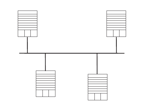
OSPF 101
Figure 6 Configuring DR Election Based on OSPF Priority
The commands listed in the following examples enable Switch A and Switch C to
be DR and BDR. The priority of Switch A is 100, which is the highest on the
network, so it is elected as the DR. Switch C has the second highest priority, so it is
elected as the BDR. The priority of Switch B is 0, which means that it cannot be
elected as the DR, and Switch D does not have a priority, which takes 1 by default.
1Configure Switch A:
[Switch A]interface Vlan-interface 1
[Switch A-Vlan-interface1]ip address 196.1.1.1 255.255.255.0
[Switch A-Vlan-interface1]ospf dr-priority 100
[Switch A]router id 1.1.1.1
[Switch A]ospf
[Switch A-ospf-1]area 0
[Switch A-ospf-1-area-0.0.0.0]network 196.1.1.0 0.0.0.255
2Configure Switch B:
[Switch B]interface Vlan-interface 1
[Switch B-Vlan-interface1]ip address 196.1.1.2 255.255.255.0
[Switch B-Vlan-interface1]ospf dr-priority 0
[Switch B]router id 2.2.2.2
[Switch B]ospf
[Switch B-ospf-1]area 0
[Switch B-ospf-1-area-0.0.0.0]network 196.1.1.0 0.0.0.255
3Configure Switch C:
[Switch C]interface Vlan-interface 1
[Switch C-Vlan-interface1]ip address 196.1.1.3 255.255.255.0
[Switch C-Vlan-interface1]ospf dr-priority 2
[Switch C]router id 3.3.3.3
[Switch C]ospf
[Switch C-ospf-1]area 0
[Switch C-ospf-1-area-0.0.0.0]network 196.1.1.0 0.0.0.255
4Configure Switch D:
[Switch D]interface Vlan-interface 1
[Switch D-Vlan-interface1]ip address 196.1.1.4 255.255.255.0
[Switch D]router id 4.4.4.4
Switch A
1.1.1.1
DR
Switch D
4.4.4.4
Switch B
2.2.2.2
Switch C
3.3.3.3
BDR
196.1.1.4/24
196.1.1.3/24196.1.1.2/24
196.1.1.1/24
102 CHAPTER 5: IP ROUTING PROTOCOL OPERATION
[Switch D]ospf
[Switch D-ospf-1]area 0
[Switch D-ospf-1-area-0.0.0.0]network 196.1.1.0 0.0.0.255
On Switch A, execute the display ospf peer command to display the OSPF
neighbors. Note that Switch A has three neighbors.
The state of each neighbor is full, which means that adjacency is set up between
Switch A and each neighbor. Switch A and Switch C should set up adjacencies
with all the routers on the network so that they can serve as the DR and BDR on
the network. Switch A is DR, while Switch C is BDR on the network, and all the
other neighbors are DR others (which means that they are neither DRs nor BDRs).
5Modify the priority of Switch B to 200:
[Switch B-Vlan-interface2000]ospf dr-priority 200
In Switch A, execute the display ospf peer command to show its OSPF
neighbors. Note that the priority of Switch B has been modified to 200, but it is
still not the DR.
Only when the current DR is offline, does the DR change. Shut down Switch A,
and run the display ospf peer command on Switch D to display its neighbors.
Note that the original BDR (Switch C) becomes the DR, and Switch B is the BDR
now.
If all switches on the network are removed and added again, Switch B is elected as
the DR (with the priority of 200), and Switch A becomes the BDR (with a priority of
100). To switch off and restart all the switches initiates a new round of DR and
BDR selection.
Configuring OSPF Virtual Links
In Figure 7, Area 2 and Area 0 are not directly connected. Area 1 is used as the
transit area for connecting Area 2 and Area 0.
Figure 7 OSPF Virtual Link Configuration
The commands listed below implement this configuration.
1Configure Switch A:
[Switch A]interface Vlan-interface 1
Switch A
1.1.1.1
Switch B
2.2.2.2
Switch C
3.3.3.3
Virtual
Link
Area 0
Area 1
Area 2
197.1.1.2/24
197.1.1.1/24
196.1.1.2/24
196.1.1.1/24
152.1.1.1/24
OSPF 103
[Switch A-Vlan-interface1]ip address 196.1.1.1 255.255.255.0
[Switch A]router id 1.1.1.1
[Switch A]ospf
[Switch A-ospf]area 0
[Switch A-ospf-area-0.0.0.0]network 196.1.1.0 0.0.0.255
2Configure Switch B:
[Switch B]interface vlan-interface 7
[Switch B-Vlan-interface7]ip address 196.1.1.2 255.255.255.0
[Switch B]interface vlan-interface 8
[Switch B-Vlan-interface8]ip address 197.1.1.2 255.255.255.0
[Switch B]router id 2.2.2.2
[Switch B]ospf
[Switch B-ospf]area 0
[Switch B-ospf-area-0.0.0.0]network 196.1.1.0 0.0.0.255
[Switch B-ospf-area-0.0.0.0]quit
[Switch B-ospf]area 1
[Switch B-ospf-area-0.0.0.1]network 197.1.1.0 0.0.0.255
[Switch B-ospf-area-0.0.0.1]vlink-peer 3.3.3.3
3Configure Switch C:
[Switch C]interface Vlan-interface 1
[Switch C-Vlan-interface1]ip address 152.1.1.1 255.255.255.0
[Switch C]interface Vlan-interface 1
[Switch C-Vlan-interface1]ip address 152.1.1.1 255.255.255.0
[Switch C]interface Vlan-interface 2
[Switch C-Vlan-interface2]ip address 197.1.1.1 255.255.255.0
[Switch C]router id 3.3.3.3
[Switch C]ospf
[Switch C-ospf]area 1
[Switch C-ospf-area-0.0.0.1]network 197.1.1.0 0.0.0.255
[Switch C-ospf-area-0.0.0.1]vlink-peer 2.2.2.2
[Switch C-ospf-area-0.0.0.1]quit
[Switch C-ospf]area 2
[Switch C-ospf-area-0.0.0.2]network 152.1.1.0 0.0.0.255
Troubleshooting OSPF
1OSPF has been configured according to the previous procedures, but OSPF on the
router does not run normally.
■Troubleshoot locally
Check whether the protocol between two directly connected routers is
operating normally. The normal sign is the peer state machine between the two
routers reaches the “FULL” state. Note that on a broadcast or NBMA network,
if the interfaces for two routers are in the DROther state, the peer state
machine for the two routers is in the 2-way state, instead of the FULL state. The
peer state machine between the DR or BDR, and all the other routers is in the
FULL state.
■Execute the display ospf peer command to view peers.
■Execute the display ospf interface command to view OSPF information in
the interface.
■Execute the ping command to test whether the physical connections and
the lower level protocol operate normally. If the local router cannot ping the

104 CHAPTER 5: IP ROUTING PROTOCOL OPERATION
peer router, it indicates that faults have occurred to the physical link and the
lower level protocol.
■If the physical link and the lower layer protocol are normal, check the OSPF
parameters configured on the interface. The parameters should be the same
parameters configured on the router adjacent to the interface. The same
area ID should be used, and the networks and the masks should also be
consistent. (The P2P or virtually linked segment can have different segments
and masks.)
■Insure that the dead timer on the same interface is at least four times the
value of the hello timer.
■If the network type is NBMA, the peer must be manually specified, using the
peer ip-address command.
■If the network type is broadcast or NBMA, there must be at least one
interface with a priority greater than zero.
■If an area is set as the STUB area to which the routers are connected, the
area on these routers must also be set as a STUB area.
■The same interface type should be adopted for the neighboring routers.
■If more than two areas are configured, at least one area should be
configured as the backbone area with an area ID of 0.
■Ensure that the backbone area connects with all other areas.
■The virtual links cannot pass through the STUB area.
■Troubleshooting globally
If OSPF cannot discover remote routes and OSPF has been configured
according to the previous procedures, and you have checked all local
troubleshooting items, verify the following configurations.
■If more than two areas are configured on a router; at least one area should
be configured as the backbone area.
As shown in Figure 8, RTA and RTD are each configured to belong to only
one area, whereas RTB and RTC are both configured to belong to two
areas. RTB belongs to area0, which complies with the backbone area
membership requirement. However, RTC does not belong to area0.
Therefore, a virtual link must be set up between RTC and RTB to insure that
area2 and area0 (the backbone area) are connected.
Figure 8 OSPF Areas
■The backbone area (area0) cannot be configured as the STUB area and the
virtual link cannot pass through the STUB area. So, if a virtual link has been
set up between RTB and RTC, neither area1 nor area0 can be configured as
a STUB area. Only area2 can be configured as a STUB area.
■Routers in the STUB area cannot redistribute the external routes.
RTA RTB RTC RTD
area0 area1 area2

IS-IS 105
IS-IS Intermediate System-to-Intermediate System (IS-IS) intra-domain routing
information exchange protocol is the dynamic routing protocol used in the AS
issued by the International Organization for Standardization (ISO). An intermediate
system (IS) in the OSI reference model is basically equivalent to a router in the
TCP/IP reference model. The IS-IS protocol, based on the link state algorithm, uses
the Shortest Path First (SPF) algorithm. It is similar to the Open Shortest Path First
(OSPF) protocol.
Integrated IS-IS is an implementation of IS-IS for IP regulated by the IETF.
This section introduces IS-IS routing protocol terms.
■Intermediate System (IS). An IS equals a router of TCP/IP. It is the basic unit in
the IS-IS protocol used for propagating routing information and generating
routes. In the following text, IS is equal to router.
■End System (ES). An ES equals the host system of TCP/IP. An ES does not
process the IS-IS routing protocol, and therefore it can be ignored in the IS-IS
protocol.
■Routing Domain (RD). A group of ISs exchange routing information with the
same routing protocol in a routing domain.
■Area. Area is the division unit in the routing domain.
■Link State DataBase (LSDB). All the link states in the network form the LSDB. In
an IS, at least one LSDB is available. The IS uses the SPF algorithm and the LSDB
to generate its own routes.
■Link State Protocol Data Unit (LSP). In the IS-IS, each IS will generate an LSP
which contains all the link state information of the IS. Each IS collects all the
LSPs in the local area to generate its own LSDB.
■Network Protocol Data Unit (NPDU). NPDUs are the network layer packets of
ISO and are basically equivalent to the IP packet of TCP/IP.
■Designated Intermediate System (DIS), is the elected router on the broadcast
network, equivalent to the DR in OSPF.
■Network Service Access Point (NSAP) is the ISO network layer address. It
identifies an abstract network service access point and describes the network
address for ISO model routing.
Configuring IS-IS is described in the following sections:
■Two-Level Structure of IS-IS
■NSAP Structure of IS-IS
■IS-IS Packets
■Configuring Integrated IS-IS
■Integrated IS-IS Configuration Example
Two-Level Structure of
IS-IS
IS-IS adopts a two-level structure, Level-1 and Level-2, in a routing domain (or an
AS) to support a large-scale routing network. A large RD is divided into one or
more areas. The Level-1 routers manage the intra-area routing and are responsible
for communicating with other Level-1 routers in the same area. The Level-2
routers manage the inter-area routing.
106 CHAPTER 5: IP ROUTING PROTOCOL OPERATION
All the Level-2 routers make up the backbone network of the RD, which is
responsible for the inter-area communications. Every area has at least one router
located on both Level-1 and Level-2 (called a Level-1/Level-2 router), which
connects the area to the backbone network. A Level-1/Level-2 router contiguous
with a router in some other area will notify the Level-1 routers in the local area
that it is an exit point from the area.
For an NPDU to go from its own area to another area, a Level-1 router will first
transmit it to the nearest Level-1/Level-2 router in the local area, regardless of its
actual destination area. Then, the NPDU will be transmitted over the Level-2
backbone network to a Level-1 router in the destination area. Finally the Level-1
router transmits the NPDU to the destination.
Figure 9 illustrates a network running the IS-IS routing protocol and composed of
two RDs, Routing Domain 1 and Routing Domain 2. Routing Domain 1 includes
two areas, Area 1 and Area 2, and Routing Domain 2 only has Area 3. In Routing
Domain 1, the three ISs connected by bold lines compose the area backbone. They
are all Level-1/Level-2 routers. The other 4 ISs not connected by bold line are
Level-1 routers.
IS-IS 107
Figure 9 IS-IS Topology
NSAP Structure of IS-IS Figure 10 illustrates the NSAP structure. The whole address is of 8 to 20 bytes
long.
Figure 10 NSAP Structure
NSAP includes initial domain part (IDP) and domain specific part (DSP). IDP and
DSP are length-variable with a total length of 20 bytes. The IDP is composed of the
108 CHAPTER 5: IP ROUTING PROTOCOL OPERATION
authority and format identifier (AFI) and initial domain identifier (IDI). The AFI
defines the format of the IDI. The DSP has several bytes.
The Area Address is composed of routing field and area identifier. The routing field
includes the AFI and the IDI and may also include the first byte of the DSP. It
identifies the organizational structure. It is followed by a 16-bit area identifier.
The following 48 bits (or 6 bytes) of System ID identifies the host or router
uniquely. A router that belongs to different areas has only one identifier.
NSAP Selector (SEL) of 8 bits does not select routes but equals the protocol
identifier of IP. Different transmission protocols correspond to different identifiers.
All the SELs of IP are 00.
AFI+IDI+HO-DSP+System ID+SEL composes the Network Entity Title, or NET for
short, which indicates the area address and system ID for routing. The ID should be
unique inside the whole area and on the backbone (Level-2).
For example, there is a NET 47.0001.aaaa.bbbb.cccc.00, in which,
Area=47.0001, System ID=aaaa.bbbb.cccc, SEL=00.
For example, there is a NET 01.1111.2222.4444.00, in which,
Area=01, System ID=1111.2222.4444, and SEL=00.
IS-IS Packets IS-IS packets are directly encapsulated in the data link frames and mainly divided
into 4 kinds, IIH, LSP, CSNP, and PSNP.
■Intermediate System to Intermediate System Hello PDU (IIH). This packet is
transmitted regularly to detect whether a contiguous system is running IS-IS
This supports establishing adjacency and allows data to be propagated in Link
State Protocol Data Units (LSPs).
■Link State Protocol Data Unit (LSP). This packet is used for propagating link
state records throughout the area. LSPs includes Level-1 LSPs and Level-2 LSPs.
Level-2 LSPs contain information about all reachable areas. Level-1 LSPs are
only used for the local area.
■Complete Sequence Numbers Protocol Data Unit (CSNP). CSNP includes Level-1
CSNP and Level-2 CSNP. The CSNP is used for database synchronization. The
DIS transmits to CSNPs (every 10 seconds by default) regularly on the broadcast
network. Over the p2p serial line, the CSNP is transmitted only when the
adjacent relationship is established for the first time.
■Partial Sequence Numbers Protocol Data Unit (PSNP). PSNP includes Level-1
PSNPs and Level-2 PSNPs. The PSNP supports the database synchronization.
Over the p2p link, the routers transmit PSNP as Ack response to acknowledge
the receipt of a certain LSPs. Also, if a router finds, from the received CSNP, that
it is missing some data (or the original database is older), it will transmit a PSNP
requesting a new LSP.
For more information, refer to relevant documentation, such as ISO 10589.
IS-IS 109
Configuring Integrated
IS-IS
Integrated IS-IS is designed to function as a routing protocol for IP. Therefore, the
network must be set up with IP addresses and VLANs in the same way that is
required for RIP or OSPF. This set up is not discussed in this section.
Beyond the standard IP setup, you must decide what type of routing hierarchy to
implement. For example, should all routers be set up as level-2 or level-1 routers or
should a level- 2 backbone be constructed connecting various level-1 areas?
Regardless of your decision, the following configuration tasks are required for IS-IS
to function as a routing protocol:
■Enabling IS-IS globally
■Setting up the desired VLANs and IP interfaces
■Setting the network entity title
■Enabling IS-IS on the required interfaces
Beyond these required commands, the following configuration tasks are common:
■Setting the router type and level, and the interface level based on the routing
hierarchy you select
■Setting the cost of an interface to optimize routing decisions
■Setting authentication at the interface, area, or domain level using simple
password or MD5 authentication
■Setting default route generation
■Importing routes from, or exporting routes to, other protocols. To export to a
protocol, see the section that discusses that protocol.
All of these commands are discussed in this section. This section also describes
other commands that are used less frequently. For example, most users should not
change the default values of the various protocol timers, nor do they need to
change the SPF calculation parameters. Other commands described may be used
under specific network conditions (large number of routes, highly meshed designs)
to either optimize or troubleshoot IS-IS.
IS-IS configuration tasks are discussed in the following sections:
■Enabling IS-IS and Entering the IS-IS View
■Setting the Network Entity Title (NET)
■Enabling IS-IS on the Specified Interface
■Configuring IS-IS Route Metric Type
■Setting IS-IS Link State Routing Cost
■Setting the Hello Packet Broadcast Interval
■Setting the CSNP Packet Broadcast Interval
■Setting the LSP Packet Interval
■Setting the LSP Packet Retransmission Interval
■Setting the Hello Failure Interval
■Setting the Priority for DIS Election
■Setting the Interface Circuit Level

110 CHAPTER 5: IP ROUTING PROTOCOL OPERATION
■Setting IS-IS Authentication
■Setting the Mesh Group of the Interface
■Setting the Router Type
■Setting Default Route Generation
■Setting a Summary Route
■Setting the Overload Flag Bit
■Setting to Ignore the LSP Checksum Errors
■Setting Peer Change Logging
■Setting the LSP Refresh Interval
■Setting the Lifetime of LSP
■Setting the SPF Calculation in Slice
■Setting SPF to Release CPU Resources
■Setting the SPF Computing Interval
■Enabling or Disabling the Interface to Send Packets
■Configuring IS-IS to Import Routes of Other Protocols
■Configuring IS-IS Route Filtering
■Setting the Preference of the IS-IS Protocol
■Resetting All the IS-IS Data Structures
■Resetting the Specified IS-IS Peer
■Displaying and Debugging IS-IS
Enabling IS-IS and Entering the IS-IS View
To run the IS-IS protocol, you need to create an IS-IS routing process.
After creating an IS-IS routing process in system view, you should also set the
Network Entity Title (NET) and activate this routing process at an interface that
may be adjacent to another router. After that, the IS-IS protocol can be started and
run.
Perform the following configuration in system view.
The tag parameter identifies the IS-IS process. In the present version, just one IS-IS
process is allowed.
By default, the IS-IS routing process is disabled.
Setting the Network Entity Title (NET)
Network Entity Titles (hereafter referred to as NETs) define the current IS-IS area
addresses and the system ID of the router.
Tab le 54 Enabling IS-IS and Entering the IS-IS View
Operation Command
Enable IS-IS and enter the IS-IS view isis [ tag ]
Cancel the specified IS-IS routing process undo isis [ tag ]

IS-IS 111
Perform the following configuration in IS-IS view.
The format of parameter net is X…X.XXXXXXXXXXXX.XX, among which the first
“X…X” is the area address, the twelve Xs in the middle is the System ID of the
router. The last XX should be 00.
CAUTION: A router can be configured with multiple area addresses. However, the
routers in the same area should be configured with the same area address. Every
router must have a unique System ID.
Enabling IS-IS on the Specified Interface
After enabling IS-IS, you must specify on which interfaces IS-IS will run.
Perform the following configurations in VLAN interface view.
Configuring IS-IS Route Metric Type
IS-IS routing protocol has two styles of route metrics:
■Narrow: the value of route metric ranges from 1 to 63.
■Wide: the value of route metric ranges from 1 to 16777215.
The switch can choose either or both of the styles.
Perform the following configuration in IS-IS view.
By default, IS-IS only receives and sends the packets whose route metric is in
narrow style.
Setting IS-IS Link State Routing Cost
Users can configure the interface (default routing) cost.
Table 55 Setting the Network Entity Title (NET)
Operation Command
Set Network Entity Title (NET) network-entity net
Delete a NET undo network-entity net
Table 56 Enabling IS-IS on the Specified Interface
Operation Command
Enable IS-IS on the specified Interface isis enable [ tag ]
Cancel this designation undo isis enable [ tag ]
Table 57 Configuring the Style for Route Metric Values of IS-IS Packets
Operation Command
Configure the style for route metric values of
IS-IS packets
cost-style { narrow | wide |
wide-compatible | { compatible |
narrow-compatible } [ relax-spf-limit ] }
Restore the default settings undo cost-style

112 CHAPTER 5: IP ROUTING PROTOCOL OPERATION
Perform the following configuration in VLAN interface view..
If the level is not specified, the default setting is, Level-1 routing cost.
The value parameter is configured according to the link state of the Interface.
By default, the routing cost of IS-IS on an interface is 10.
Setting the Hello Packet Broadcast Interval
The IS-IS periodically sends Hello packets from the Interface, and the routers
maintain adjacency through the transmission and receipt of Hello packets The
Hello packet interval can be modified.
Usually, on broadcast links, there exist level-1 and level-2 hello packets. If you
want a different hello interval for Level-1 and Level-2, you must set the intervals
separately. However, there are two exceptions. One exception is when there is no
level separation in the link, parameters of level-1 and level-2 need not be specified
in the command.
The other exception is that attributes of the packets do not need to be set if hello
packets are not separated according to level-1 and level-2 on the p2p links.
Perform the following configurations in VLAN interface view..
By default, Hello packets are transmitted on an interface every 10 seconds.
Setting the CSNP Packet Broadcast Interval
The CSNP packet is transmitted by the DIS over the broadcast network to
synchronize the link state database (LSDB). The CSNP packet is regularly broadcast
over the broadcast network at an interval, which can be set by users.
Perform the following configuration in VLAN interface view.
Tab le 58 Setting IS-IS Link State Routing Cost
Operation Command
Set the routing cost of the interface isis cost value [ level-1 | level-2 ]
Restore the default routing cost of the
interface
undo isis cost [ level-1 | level-2 ]
Tab le 59 Setting the Hello Packet Broadcast Interval
Operation Command
Set Hello packet interval, measured in
seconds.
isis timer hello seconds [ level-1 | level-2 ]
Restore the default Hello packet interval on
the interface
undo isis timer hello [ level-1 | level-2 ]
Tab le 60 Setting the CSNP Packet Broadcast Interval
Operation Command
Set the CSNP packet broadcast interval,
measured in seconds
isis timer csnp seconds [ level-1 | level-2 ]
Restore the default CSNP packet broadcast
interval on the interface
undo isis timer csnp [ level-1 | level-2 ]

IS-IS 113
If the level is not specified, it defaults to setting the CSNP packet broadcast interval
for Level-1.
By default, the CSNP packet is transmitted by an interface every 10 seconds.
Setting the LSP Packet Interval
LSP carries the link state records for propagation throughout the area.
Perform the following configuration in VLAN interface view..
By default, the minimum time between the consecutive transmissions of 2 LSPs is
33 milliseconds.
Setting the LSP Packet Retransmission Interval
If the local end does not receive a response within a period of time after it sends
an LSP packet over a p2p link, it assumes that the LSP packet has been lost or
dropped. To guarantee transmission reliability, the local router will retransmit the
original LSP packet.
Perform the following configurations in VLAN interface view..
By default, the LSP packet is transmitted every 5 seconds over the p2p link.
Setting the Hello Failure Interval
The IS-IS protocol maintains adjacency between routers by transmitting and
receiving Hello packets. If the local router does not continuously receive Hello
packets within the time interval transmitted by the peer, it considers the adjacent
router to be down.
Perform the following configurations in VLAN interface view..
Table 61 Setting the LSP Packet Interval
Operation Command
Set LSP packet interval on the interface,
measured in milliseconds.
isis timer lsp time
Restore the default LSP packet interval on the
interface
undo isis timer lsp
Table 62 Setting LSP Packet Retransmission Interval
Operation Command
Set the retransmission interval of the LSP
packet over p2p links
isis timer retransmit seconds
Restore the default retransmission interval of
the LSP packet over p2p links
undo isis timer retransmit
Table 63 Setting the Hello Failure Interval on the Interface
Operation Command
Set the Hello failure interval on the interface isis timer dead seconds [ level-1 | level-2 ]
Restore the default Hello failure interval on
the interface
undo isis timer dead [ level-1 | level-2 ]

114 CHAPTER 5: IP ROUTING PROTOCOL OPERATION
By default, the Hello failure interval is 30 seconds. If the level is not specified, it
defaults to setting the Hello packet failure interval Level-1.
Setting the Priority for DIS Election
In the broadcast network, the IS-IS needs to elect a DIS from all the routers.
In IS-IS, both a Level-1 and a Level-2 DIS are selected, based on priority. An
IS/router with a higher priority will be selected as DIS over a router with a lower
priority. If there are two or more routers with the highest priority in the broadcast
network, the one with the greatest MAC address will be selected. If all the
adjacent routers' priorities are 0, the one with the greatest MAC address will be
selected.
The DISs of Level-1 and Level-2 are elected separately. You can set different
priorities for DIS election at different levels.
Perform the following configuration in VLAN interface view..
By default, the interface priority is 64. If the level is not specified, it defaults to the
priority of Level-1.
Setting the Interface Circuit Level
Perform the following configuration in VLAN interface view..
You can set the circuit level to limit what type of adjacency can be established for
the interface. For example, a Level-1 interface can only establish a Level-1
adjacency. A Level-2 interface can only establish a Level-2 adjacency. For the
Level-1-2 router, you can configure some interfaces as Level-2 to prevent
transmitting Level-1 Hello packets on the Level-2 backbone and conserve
bandwidth. However Level-1 and Level-2 use the same kind of Hello packet over
the p2p link, and therefore such a setting is unnecessary.
By default, the circuit-level on an interface is level-1-2.
Setting IS-IS Authentication
Setting IS-IS authentication involves tasks described in the following three
sections.
Tab le 64 Setting Priority for DIS Election
Operation Command
Set the priorities for DIS election on the
interface
isis dis-priority value [ level-1 | level-2 ]
Restore the default priorities for DIS election
on the interface
undo isis dis-priority [ level-1 | level-2 ]
Tab le 65 Setting the Interface Circuit Level
Operation Command
Set the interface circuit level isis circuit-level [ level-1 | level-1-2 | level-2
]
Restore the default interface circuit level undo isis circuit-level

IS-IS 115
Setting Interface Authentication The authentication password set on the
interface is mainly used in the Hello packet to confirm the validity and correctness
of its peers. The authentication passwords at the same level for all the connected
interfaces of a network should be identical.
Perform the following configurations in VLAN interface view..
By default, the interface is not configured with any authentication password and
does not perform authentication. If the level is not specified when you set
authentication, it defaults to set the authentication password of Level-1.
IP or OSI authentication mode is not related to whether IP or OSI CLNP packet
forwarding is used. OSI authentication mode is most common.
Setting the IS-IS Area or IS-IS Routing Domain Authentication Password
Users can configure the IS-IS area or the IS-IS routing domain with an
authentication password.
If area authentication is needed, the area authentication password will be
encapsulated into the level-1 LSP, CSNP and PSNP packets, using the specified
mode (md5 or simple text). All routers in the same area must have identical
passwords and authentication modes to work together correctly. Similarly, for
domain authentication, the password will be encapsulated into the level-2 LSP,
CSNP and PSNP packets using the specified mode. If the routers in the backbone
layer (level-2) need domain authentication, the authentication mode and
password must be identical on all.
The passwords for authentication of the routers on the same network segment
must be identical.
Perform the following configurations in IS-IS view.
By default, the system does not require passwords or perform authentication.
Table 66 Setting the Interface Authentication Password
Operation Command
Set the authentication password isis authentication-mode { simple | md5 }
password [ { level-1 | level-2 } [ ip | osi ] ]
Delete the authentication-mode password undo isis authentication-mode { simple |
md5 } password [ { level-1 | level-2 } [ ip | osi
] ]
Table 67 Setting IS-IS Authentication Password
Operation Command
Set authentication-mode password area-authentication-mode { simple | md5 }
password [ ip | osi ]
Delete authentication-mode password undo area-authentication-mode { simple |
md5 } [ ip | osi ]
Set routing domain authentication password domain-authentication-mode { simple |
md5 } password [ ip | osi ]
Delete routing domain authentication
password
undo domain-authentication-mode {
simple | md5 } [ ip | osi ]

116 CHAPTER 5: IP ROUTING PROTOCOL OPERATION
Setting the IS-IS to Use the MD5 Algorithm That Is Compatible With Other
Vendors’ You must configure this command when the switch needs to
authenticate the devices of other vendors using MD5 algorithm in IS-IS.
Perform the following configurations in IS-IS view.
By default, the system uses the MD5 algorithm in IS-IS that is compatible with the
3Com algorithm.
Setting the Mesh Group of the Interface
On NBMA network, the interface of a router will flood the received LSP to other
interfaces. However, this processing method applied to a network with higher
connectivity and several p2p links will cause repeated LSP flooding and waste
bandwidth.
To avoid this problem, you can configure several interfaces into a mesh group. The
interface will flood outside the group only.
Perform the following configurations in VLAN interface view..
By default, the LSP is flooded normally from the interface. When configured with
the mesh-blocked parameter, it will not flood the LSP to other interfaces.
The IS-IS configuration tasks on the interface are finished. The following sections
discuss how to configure other parameters of IS-IS.
Setting the Router Type
Users can set the level for the current router; based upon the location of the router
in the network, Level-1 (intra-domain router), Level-2 (inter-domain router) and
Level-1-2 (intra-domain router as well as inter-domain router) can be selected.
Perform the following configurations in IS-IS view..
By default, the router type is level-1-2.
Tab le 68 Set IS-IS to use the MD5 Algorithm that is Compatible With Other Vendors’
Operation Command
Set the IS-IS to use the MD5 algorithm that is
compatible with the algorithm of another
vendor
md5-compatible
Set the IS-IS to use the default MD5 algorithm undo md5-compatible
Tab le 69 Setting the Mesh Group of the Interface
Operation Command
Add an interface to a mesh group. isis mesh-group { mesh-group-number |
mesh-blocked }
Remove the interface from the mesh group undo isis mesh-group
Tab le 70 Setting the Router Type
Operation Command
Set router type is-level { level-1 | level-1-2 | level-2 }
Restore the default router type undo is-level

IS-IS 117
Setting Default Route Generation
In an IS-IS route domain, a Level-1 router only has the LSDB for the local area, so it
can only generate routes for the local areas. The Level-2 router has the backbone
LSDB for the IS-IS route domain and generates backbone network routes only. If a
Level-1 router in one area wants to forward packets to other areas, it must first
forward the packets to the closest Level-1-2 router in the local area according to
its default route.
Perform the following configurations in IS-IS view..
The default route generated by this command will only be propagated to routers
at the same level.
By default, a Level-1-2 router will set its attach bit if it is connected to the
backbone. This creates a default route out of the attached Level-1 area. Additional
default routes (from the Level-2 backbone to another AS, for example) can be set
using this command and route policy.
Setting a Summary Route
You can aggregate several different routes. This converts the advertisement
processes of several routes into the advertisement of a single route and simplifies
the routing table.
Perform the following configurations in IS-IS view..
By default, routing summarization is disabled.
Setting the Overload Flag Bit
Sometimes, router in the IS-IS domain may encounter operational problems that
can affect the entire routing area.
In order to avoid this problem, we can set the overload flag bit for this router.
When the overload threshold is set on a router, other routers should not send
packets for this router to forward. However, other routers can still forward packets
to be delivered to network segments that are directly attached to the router.
Table 71 Setting Default Route Generation
Operation Command
Set to generate default route default-route-advertise [ route-policy
route-policy-name ]
Set not to generate default route undo default-route-advertise [
route-policy route-policy-name ]
Table 72 Setting a Summary Route
Operation Command
Set summary route summary ip-address ip-mask [ level-1 |
level-1-2 | level-2 ]
Delete the summary route undo summary ip-address ip-mask [ level-1 |
level-1-2 | level-2 ]

118 CHAPTER 5: IP ROUTING PROTOCOL OPERATION
Perform the following configurations in IS-IS view.
By default, no overload bit is set.
Setting to Ignore the LSP Checksum Errors
After receiving an LSP packet, the local IS-IS calculates its checksum and compares
the result with the checksum in the LSP packet. By default, if the checksum in the
packet is found to be inconsistent with the calculated result, the LSP is processed
and rejected. In networks that are prone to corruption, this could result in a packet
corruption storm. However, if the ignore-lsp-checksum-error command is
executed, the LSP will be discarded silently when a checksum error is found .
Perform the following configurations in IS-IS view..
By default, LSP checksum errors are not ignored.
Setting Peer Change Logging
After peer change logging is enabled, IS-IS peer changes will be output on the
configuration terminal until logging is disabled.
Perform the following configuration in IS-IS view..
By default, the peer change logging is disabled.
Setting the LSP Refresh Interval
In order to ensure that the LSPs in the whole area can maintain synchronization, all
current LSPs will be transmitted periodically.
Perform the following configurations in IS-IS view.
Tab le 73 Setting Overload Flag Bit
Operation Command
Set overload flag bit set-overload
Remove the overload flag bit undo set-overload
Tab le 74 Setting to Ignore the LSP Checksum Errors
Operation Command
Discard the LSPs with checksum errors ignore-lsp-checksum-error
Set not to discard the LSP checksum errors undo ignore-lsp-checksum-error
Tab le 75 Setting to Log the Peer Changes
Operation Command
Enable peer changes log log-peer-change
Disable peer changes log undo log-peer-change
Tab le 76 Setting LSP Refresh Interval
Operation Command
Set LSP refresh interval timer lsp-refresh seconds
Restore the default LSP refresh interval undo timer lsp-refresh

IS-IS 119
By default, an LSP is refreshed every 900 seconds (15 minutes).
Setting the Lifetime of LSP
When a router generates an LSP, it sets the maximum lifetime of the LSP. When
other routers receive this LSP, they reduce its lifetime continuously as time passes.
If an updated LSP has not been received before the old one times out, the LSP is
deleted from the LSDB.
Perform the following configurations in IS-IS view..
By default, an LSP pages out after 1200 seconds (20 minutes).
Setting the SPF Calculation in Slice
When there are a large number of routes in the routing table (over 150,000), the
IS-IS SPF calculation can occupy system resources for an extended time. To prevent
this, the SPF calculation can be set to execute in slices.
Perform the following configuration in IS-IS view.
By default, the SPF calculation is not divided into slices but runs to completion.
This can also be implemented by setting the parameter seconds to 0.
After slice calculation is set, the routes that are not processed at once will be
calculated after one second.
Normally, you should not modify the default configuration. When the number of
routes is between 150,000 and 200,000, you should set the parameter seconds to
1, that is, the duration time for SPF calculation each time is 1 second.
Setting SPF to Release CPU Resources
To prevent SPF calculation from occupying the system resources for a long time,
which impacts the response speed of the console, SPF can be set to automatically
release the system CPU resources after processing a certain number of routes. The
unprocessed routes will be calculated after one second.
Table 77 Setting Lifetime of LSP
Operation Command
Set lifetime of LSP timer lsp-max-age seconds
Restore the default LSP lifetime undo timer lsp-max-age
Table 78 Setting SPF Calculation in Slice
Operation Command
Set the duration of one cycle for SPF
calculation
spf-slice-size seconds
Restore the default configuration undo spf-slice-size

120 CHAPTER 5: IP ROUTING PROTOCOL OPERATION
Perform the following configurations in IS-IS view..
By default, the CPU is released after 5000 routes are processed by the SPF of IS-IS.
Setting the SPF Computing Interval
When the IS-IS LSDB changes, the router will compute the shortest path again.
However, an immediate calculation upon every change will occupy too many
resources and affect the efficiency of the router. If the SPF computing interval is
set, and the LSDB changes, the SPF algorithm will be run after the SPF interval
times out.
Perform the following configurations in IS-IS view..
If the level is not specified, it defaults to setting the SPF computing interval for
Level-1.
By default, the SPF calculation runs every 5 seconds.
Enabling or Disabling the Interface to Send Packets
Use the silent-interface command to prevent an interface from sending IS-IS
routing information to a router in a network.
Perform the following configurations in IS-IS view..
By default, the interface is allowed to receive and send IS-IS packets.
The silent-interface command is only used to prevent the IS-IS packets from
being sent on the interface, but interface routes can still be sent from other
interfaces.
Tab le 79 Setting SPF to Release CPU Resources
Operation Command
Set the number of routes to process before
releasing the CPU
spf-delay-interval number
Restore the default configuration undo spf-delay-interval
Tab le 80 Setting SPF Computing Interval
Operation Command
Set SPF computing interval timer spf second [ level-1 | level-2 ]
Restore default SPF computing interval undo timer spf [ level-1 | level-2 ]
Tab le 81 Enabling/Disabling the Interface to Send IS-IS Packets
Operation Command
Prevent the interface from sending IS-IS
packets
silent-interface silent-interface-type
silent-interface-number
Allow the interface to send IS-IS packets undo silent-interface silent-interface-type
silent-interface-number

IS-IS 121
Configuring IS-IS to Import Routes of Other Protocols
For IS-IS, the routes discovered by other routing protocols are processed as routes
outside the routing domain. When importing the routes of other protocols, you
can specify their default cost.
When IS-IS imports routes, you can also specify whether to import the routes into
Level-1, Level-2 or Level-1-2.
Perform the following configurations in IS-IS view..
If the level is not specified in the command for importing the route, it defaults to
importing the routes into level-2.
protocol specifies the routing protocol sources that can be imported, which can be
direct, static, rip, bgp, and ospf, etc.
By default, IS-IS does not import routing information from any other protocols.
For more about importing routing information, see “IP Routing Policy”.
Configuring IS-IS Route Filtering
The IS-IS protocol can filter the received and distributed routes according to the
access control list specified by acl-number.
Perform the following configurations in IS-IS view.
Configuring for Filtering of the Routes Received by IS-IS
Configuring for Filtering the Distributed Routes
By default, IS-IS does not filter received and distributed routing information.
Table 82 Importing Routes of Other Protocols
Operation Command
Import routes of other protocols import-route protocol [ cost value | type {
external | internal } | [ level-1 | level-1-2 |
level-2 ] | route-policy route-policy-name ] *
Configure not to import routes from other
protocols
undo import-route protocol [ cost value |
type { external | internal } | [ level-1 |
level-1-2 | level-2 ] | route-policy
route-policy-name ] *
Table 83 Configuring for Filtering of Received Routes
Operation Command
Allow filtering of received routes filter-policy acl-number import
Prevent filtering of received routes undo filter-policy acl-number import
Table 84 Configuring for Filtering of Distributed Routes
Operation Command
Allow filtering of routes distributed by IS-IS filter-policy acl-number out protocol
Prevent filtering of routes distributed by IS-IS undo filter-policy acl-number out protocol

122 CHAPTER 5: IP ROUTING PROTOCOL OPERATION
Protocol specifies the routing protocol sources for distributing routes, which can
be direct, static, rip, bgp, ospf, or ospf-ase.
For more information, see “Configuring for Filtering Received Routes” and
“Configuring for Filtering Distributed Routes ”.
Setting the Preference of the IS-IS Protocol
In a router where several routing protocols are concurrently operating, there is an
issue of sharing and selecting the routing information among all the routing
protocols. The system sets a preference for each routing protocol. When various
routing protocols find the route to the same destination, the route learned by the
protocol with the higher preference will take effect.
Perform the following configurations in IS-IS view..
By default, the preference of IS-IS routes is 15.
Resetting All the IS-IS Data Structures
When it is necessary to refresh some LSPs immediately, perform the following
configuration in user view. This may be necessary if you change area or domain
authentication parameters.
Resetting the Specified IS-IS Peer
When it is necessary to reset peer relationships, perform the following
configuration in user view..
Displaying and Debugging IS-IS
Using the following configuration operations, you can view the IS-IS LSDB , the
transmission/receipt of IS-IS packets, IS-IS configuration, and information related
to the IS-IS SFP calculation and IS-IS route table.
Tab le 85 Configuring the Preference of IS-IS Protocol
Operation Command
Configure the preference of IS-IS protocol preference value
Restore the default preference of IS-IS
protocol
undo preference
Tab le 86 Resetting all the IS-IS Data Structures
Operation Command
Reset the IS-IS data structure reset isis all
Tab le 87 Resetting the Specified IS-IS Peer
Operation Command
Reset the specified IS-IS peer reset isis peer system-id

IS-IS 123
Execute the display command in all views to display the IS-IS configuration, and
to verify the effect of the configuration. Execute the debugging command in user
view to debug the IS-IS module.
Integrated IS-IS
Configuration Example As is shown in Figure 11, Switches A, B, C and D belong to the same autonomous
system. The IS-IS routing protocol is run in these four switches to implement route
interconnection. In network design, switches A, B, C and D belong to the same
area.
This example shows only the IS-IS configuration. You must also configure IP
addresses on the vlan interface of each switch.
Table 88 Displaying and Debugging IS-IS
Operation Command
Display IS-IS LSDB display isis lsdb [ [ l1 | l2 | level-1 | level-2 ] |
[ [ LSPID | local ] | verbose ]* ]*
Display IS-IS SPF calculation log display isis spf-log
Display IS-IS routing information display isis route
Display IS-IS neighbor information display isis peer [ verbose ]
Display mesh group information display isis mesh-group
Debug IS-IS adjacency packets debugging isis adjacency
Debug IS-IS LSP checksum errors debugging isis checksum-error
Debug IS-IS local update packets debugging isis self-originated-update
Debug IS-IS LSP errors. debugging isis general-error
Debug IS-IS SNP packets debugging isis snp-packet
Debug IS-IS SPF events. debugging isis spf-event
Debug IS-IS SPF computing statistics debugging isis spf-summary
Debug IS-IS SPF triggers. debugging isis spf-timer
Debug IS-IS update packets debugging isis update-packet
124 CHAPTER 5: IP ROUTING PROTOCOL OPERATION
Figure 11 IS-IS Configuration Example
1Configure Switch A
[Switch A]isis
[Switch A-isis]network-entity 86.0001.0000.0000.0005.00
[Switch A]interface vlan-interface 100
[Switch A-Vlan-interface100]isis enable
[Switch A]interface vlan-interface 101
[Switch A-Vlan-interface101]isis enable
[Switch A]interface vlan-interface 102
[Switch A-Vlan-interface102]isis enable
2Configure Switch B
[Switch B]isis
[Switch B-isis]network-entity 86.0001.0000.0000.0006.00
[Switch B]interface vlan-interface 101
[Switch B-Vlan-interface101]isis enable
[Switch B]interface vlan-interface 102
[Switch B-Vlan-interface102]isis enable
[Switch B]interface vlan-interface 100
[Switch B-Vlan-interface100]isis enable
3Configure Switch C
[Switch C]isis
[Switch C-isis]network-entity 86.0001.0000.0000.0007.00
[Switch C]interface vlan-interface 101

BGP 125
[Switch C-Vlan-interface101]isis enable
[Switch C]interface vlan-interface 100
[Switch C-Vlan-interface100]isis enable
4Configure Switch D
[Switch D]isis
[Switch D-isis]network-entity 86.0001.0000.0000.0008.00
[Switch D]interface vlan-interface 102
[Switch D-Vlan-interface102]isis enable
[Switch D]interface vlan-interface 100
[Switch D-Vlan-interface100]isis enable
BGP Border gateway protocol (BGP) is an inter-autonomous system (inter-AS) dynamic
route discovery protocol.
Three early versions of BGP are BGP-1 (RFC1105), BGP-2 (RFC1163) and BGP-3
(RFC1267). The current version is BGP-4 (RFC1771) that is applied to distributed
structures and supports classless inter-domain routing (CIDR). BGP-4 is becoming
the external routing protocol standard of the Internet, which is frequently used
between ISPs.
The characteristics of BGP are as follows:
■BGP is an external gateway protocol (EGP) that focuses on route propagation
control and selection of best routes, rather than the discovery and calculation
of routes.
■It eliminates routing loops by adding AS path information to BGP routes.
■It enhances its own reliability by using TCP as the transport layer protocol.
■When routes are updated, BGP only transmits updated routes, which greatly
reduces bandwidth occupation by route propagation and can be applied to
propagation of a great amount of routing information on the Internet.
■BGP-4 supports CIDR, which is an important improvement over BGP-3.
■In consideration of management and security, users can perform control over
outgoing and incoming routing information of each AS. BGP-4 provides
abundant route policies to implement flexible filtering and selecting of routes.
■BGP-4 can be scaled easily to support new developments of the network.
CIDR does not distinguish networks of Class A, Class B and Class C. For example,
an invalid Class C network address 192.213.0.0 (255.255.0.0) can be expressed as
192.213.0.0/16 in CIDR mode, which is a valid super network. Here /16 means
that the subnet mask is composed of the first 16 bits from the left.
The introduction of CIDR simplifies route aggregation, which is the process of
aggregating several different routes, and converts the advertisement processes of
several routes to the advertisement of single route to simplify the routing table.
126 CHAPTER 5: IP ROUTING PROTOCOL OPERATION
BGP runs on a router in any of the following modes:
■Internal BGP (IBGP)
■External BGP (EBGP)
BGP is called IBGP when it runs within an AS and EBGP when it runs among
different ASs.
Configuring BGP is described in the following sections:
■BGP Messages
■BGP Routing
■BGP Peers and Peer Groups
■Configuring BGP
■Typical BGP Configuration Examples
■Troubleshooting BGP
BGP Messages BGP is driven by the following types of messages:
■Open — Sent after a connection is created between BGP peers.
■Update — Used to exchange routing information between peers. This message
has up to three parts
■Unreachable route
■Path attributes
■Network layer reachability information (NLRI).
■Notification — Used for error notification.
■Keepalive — Used to check connectivity to peers.
■Route-refresh — Used to advertise its own route refreshing capability.
The open, update, notification and keepalive messages are defined in RFC1771,
while the route-refresh message is defined in RFC2918 (Route Refresh Capability
for BGP-4).
BGP Routing At startup of the BGP session, the BGP router exchanges routing information with
its peers by transmitting the complete BGP routing table. After that, only update
messages are exchanged. During operation of the system, keepalive messages are
received and transmitted to check the connections between various neighbors.
The router transmitting BGP messages is called a BGP speaker, which receives and
generates new routing information continuously and advertises the information to
the other BGP speakers. When a BGP speaker receives a new route advertisement
from another AS, it will advertise the route to all other BGP speakers in the AS, if
the route is better than the current route, or is a new route.
A BGP speaker calls other BGP speakers peers. Multiple related peers compose a
peer group.
BGP 127
Route Advertisement Policy
In the Switch 8800, BGP uses the following policies when it advertises routes:
■If there are multiple routes available, a BGP speaker only selects the optimum
one.
■A BGP speaker only advertises its own route to its peers.
■A BGP speaker advertises the routes obtained from EBGP to all its BGP peers
(including EBGP and IBGP peers).
■A BGP speaker does not advertise the routes obtained from IBGP to its other
IBGP peers.
■Once the connection is set up, a BGP speaker will advertise all its BGP routes to
its peers.
Router Selection Policy
In the Switch 8800, BGP uses the following policies when it selects routes:
■Discard the routes from an unreachable or unknown next hop.
■Select the routes with the highest local preference.
■Select the routes that originate at the router itself.
■Select the routes with the lowest number of AS-paths.
■Select the routes with the lowest origin.
■Select the routes with the lowest MED value.
■Select the routes learned from EBGP.
■Select the routes advertised by the router with the lowest ID.
BGP Peers and Peer
Groups
A BGP speaker calls other BGP speakers, peers, when they exchange information.
Multiple related peers compose of a peer group.
In the Switch 8800, a BGP peer must belong to a peer group. If you want to
configure a BGP peer, you first need to create a peer group and then add a peer
into that group.
BGP peer group feature can simplify user configuration and improve route
advertisement efficiency. When added into a peer group, a peer inherits all the
configuration of the group.
If the configuration of a peer group changes, the configuration of its member
peers also changes. Some attributes can be configured to a particular member
peer by specifying its IP address. The attributes configured in this way have a
higher priority than those configured for a peer group. Note that all member peers
must use the same update policy as its group, but may use a different ingress
policy.
Configuring BGP BGP configuration includes:
■Enabling BGP
■Entering Extended Address Family View
■Configuring Basic Features for a BGP Peer

128 CHAPTER 5: IP ROUTING PROTOCOL OPERATION
■Configuring Application Features of BGP Peer (Group)
■Configuring the Route Filtering of a Peer (Group)
■Configuring Networks for BGP Distribution
■Configuring Interaction Between BGP and IGP
■Configuring BGP Route Summarization
■Configuring BGP Route Filtering
■Configuring BGP Route Dampening
■Configuring BGP Preferences
■Configuring the BGP Timer
■Configuring Local Preferences
■Configuring MED for AS
■Comparing the MED Routing Metrics from Peers in Different ASs
■Configuring BGP Community
■Configuring a BGP Route Reflector
■Configuring BGP AS Confederation Attributes
■Defining ACLs, AS Path List, and Route-policy
■Clearing the BGP Connection
■Refreshing BGP Routes
■Displaying and Debugging BGP
Enabling BGP
To enable BGP, a local AS number must be specified. After BGP is enabled, the
local router listens to BGP connection requests sent by adjacent routers. To make
the local router send BGP connection requests to adjacent routers, refer to the
configuration of the peer command. When BGP is disabled, all established BGP
connections will be disconnected.
Perform the following configurations in system view.
By default, BGP is not enabled.
Entering Extended Address Family View
To initiate multicast applications with BGP, you must enable BGP and enter the
corresponding extended address family view. Some commands available in BGP
view can also be executed in extended address family view. However, these
commands are only available for the corresponding applications if you configure
them in extended address family view.
Tab le 89 Enabling/Disabling BGP
Operation Command
Enable BGP and enter the BGP view bgp as-number
Disable BGP undo bgp [ as-number ]

BGP 129
Perform the following configurations in BGP view.
Use the undo command to delete the application configuration. See “Multicast
Protocol” on page 63 for MBGP configuration commands.
Configuring Basic Features for a BGP Peer
In configuring a MBGP peer (group), you should first configure AS ID for it and
then enter the corresponding address family view to activate the association.
Perform the configurations in the following subsections in BGP view.
Creating a Peer Group
A BGP peer must belong to a peer group. Before configuring a BGP peer, you must
create a peer group to which the peer will belong.
There are two types of BGP peer groups, IBGP and EBGP. Use internal to create a
IBGP peer group. Use external to create a EBGP peer group and sub-AS peer
groups inside a confederation.
The default type of BGP peer group is internal.
Configuring the AS Number of an EBGP Peer Group
You can specify the AS number for an EBGP peer group, but an IBGP peer group
needs no AS number. When a peer group is specified with an AS number, all its
member peers inherit that AS number.
The AS number cannot be specified for a peer group which already has group
numbers. Deleting the AS number of a peer group deletes all member peers in
that group.
Adding a Member to a Peer Group
Table 90 Entering Extended Address Family View
Operation Command
Enter multicast sub-address family view ipv4-family multicast
Delete multicast sub-address family
configuration
undo ipv4-family multicast
Table 91 Creating a Peer Group
Operation Command
Create a peer group group group-name [ internal | external ]
Delete a specified peer group undo group group-name
Table 92 Configuring the AS Number of an EBGP Peer Group
Operation Command
Configure the AS number of the EBGP peer
group
peer group-name as-number as-number
Delete the AS number of the EBGP peer group undo peer group-name as-number
as-number

130 CHAPTER 5: IP ROUTING PROTOCOL OPERATION
A BGP peer must belong to a peer group. If you want to configure a BGP peer, you
need to first create a peer group and then add a peer to the group.
If a peer is added to an IBGP peer group, the AS number cannot be specified in the
command.
When a peer group is defined with an AS number, all its member peers inherit that
AS number. If the AS number of the peer group is not specified, each peer added
to it should be specified with its own AS number. AS numbers of peers in a same
peer group can be different.
Configuring the State of a Peer/Peer Group
A BGP peer/peer group has two states: enable and disable. The BGP speakers do
not exchange routing information with a disabled peer or peer group.
Perform the following configurations in BGP view.
By default, a BGP peer or peer group is enabled.
When exchanging routing information between BGP speakers, the peer group
must be enabled first, and then the peer should be added to the enabled peer
group.
Configuring the Description of a Peer (Group)
The description of a peer or peer group can be added to facilitate learning the
characteristics of the peer .
By default, no BGP peer (group) description is set.
Configuring the Timer of a Peer (Group)
The peer timer command is used to configure timers of BGP peer (group),
including the keep-alive message interval and the hold timer. The preference of
Tab le 93 Creating a Peer Group and Add a Member
Operation Command
Add a peer to the peer group peer peer-address group group-name [
as-number as-number ]
Delete a peer undo peer peer-address
Tab le 94 Configuring the State of a Peer/Peer Group
Operation Command
Enable a peer/peer group peer { group-name | peer-address } enable
disable a peer/peer group undo peer { group-name | peer-address }
enable
Tab le 95 Configuring the Description of a Peer Group
Operation Command
Configure description of a peer (group) peer { peer-address | group-name }
description description-line
Delete description of a peer (group) undo peer { peer-address | group-name }
description

BGP 131
this command is higher than the timer command, which is used to configure
timers for the whole BGP peers.
By default, the keep-alive message is sent every 60 seconds and the value of the
hold timer is 180 seconds.
Configuring the Route Update Interval for a Peer Group
By default, the intervals at which route update messages are sent by an IBGP and
EBGP peer group are 5 seconds and 30 seconds respectively.
Configuring Application Features of BGP Peer (Group)
Configuring Connection Permission with EBGP Peer Groups on Indirectly
Connected Networks
Generally, EBGP peers must be directly connected. The following command can be
used to configure two indirectly connected EBGP peers or peer groups.
By default, only connections with EBGP peer groups on directly connected
networks are permitted. Ttl refers to the time-to-live in the range of 1 to 255. The
default value is 64.
Configuring a Peer Group to be a Client of a Route Reflector .
Table 96 Configuring the Timer of a Peer Group
Operation Command
Configure keep-alive message interval and
hold timer of peer (group)
peer { group-name | peer-address } timer
keep-alive keepalive-interval hold
holdtime-interval}
Restore the default value of keep-alive
message interval and hold timer of a peer
(group)
undo peer { group-name | peer-address }
timer
Table 97 Configuring the Route Update Interval for a Peer Group
Operation Command
Configure the route update message interval
of a peer group
peer group-name route-update-interval
seconds
Restore the default route update message
interval of a peer group
undo peer group-name
route-update-interval
Table 98 Configuring Connection Permission with EBGP Peer Groups on Indirectly
Connected Networks
Operation Command
Permit connections with EBGP peer groups on
indirectly connected networks
peer group-name ebgp-max-hop [ ttl ]
Permit connections with EBGP peer groups on
directly connected network only.
undo peer group-name ebgp-max-hop
Table 99 Configuring a Peer Group to be a Client of a Route Reflector
Operation Command
Configure a peer group to be a client of a
route reflector
peer group-name reflect-client
Cancel the configuration of making the peer
group as the client of the BGP route reflector
undo peer group-name reflect-client

132 CHAPTER 5: IP ROUTING PROTOCOL OPERATION
For detailed information on the route reflector, see “Configuring a BGP Route
Reflector” on page 140.
Configuring Transmission of a Default Route to a Peer Group .
By default, a local router does not send a default route to any peer group.
However, if you use the peer default-route-advertise command, the local router
sends a default route, with itself as the next hop, to the peer even if there is no
default route in BGP routing table.
Configuring the BGP Router as the Next Hop in a Route
A BGP router can specify itself as the next hop while advertising a route to a peer
group.
By default, local router does not specify itself as the next hop while advertising
route to a peer group.
Removing Private AS Numbers When Transmitting BGP Update
Messages
Generally, the AS numbers (public AS numbers or private AS numbers) are
included in the AS paths while transmitting BGP update messages. This command
is used to configure a local router not to transmit private AS numbers when
transmitting update messages.
By default, the private AS numbers are included when transmitting BGP update
messages.
Tab le 100 Configuring Transmission of a Default Route to a Peer Group
Operation Command
Configure transmission of a default route to a
peer group
peer group-name default-route-advertise
Configure no transmission of a default route
to a peer group
undo peer group-name
default-route-advertise
Tab le 101 Configuring the Advertiser as the Next Hop in a Route
Operation Command
Configure itself as the next hop in advertising
route
peer group-name next-hop-local
Disable the specification of itself as the next
hop in advertising route
undo peer group-name next-hop-local
Tab le 102 Removing Private AS Numbers While Transmitting BGP Update Messages
Operation Command
Remove private AS numbers while
transmitting BGP update messages
peer group-name public-as-only
Include private AS numbers while transmitting
BGP update messages
undo peer group-name public-as-only

BGP 133
Configuring the Transmission of Community Attributes to a Peer Group
Configuring the Repeating Time of a Local AS
Using the peer allow-as-loop command, the repeating time of local AS can be
configured.
Perform the following configurations in BGP view..
Specifying the Source Interface of a Route Update Packet
Generally, the system specifies the source interface of a route update packet.
When the interface fails to work, in order to keep the TCP connection alive, the
interior BGP session can be configured to specify the source interface. This
command is usually used when using the loopback interface.
By default, BGP carries out TCP connection with the optimal source interface.
Configuring the BGP MD5 Authentication Password
BGP uses TCP as its transport layer. For security, you can configure a MD5
authentication password when setting up TCP connection. BGP MD5
authentication only sets a password for the TCP connection, but not for
authenticating BGP packets. The authentication is implemented by TCP.
Perform the following configurations in BGP view.
Table 103 Configuring for Transmission of Community Attributes to a Peer Group
Operation Command
Configure to send the community attributes
to a peer group
peer group-name advertise-community
Configure not to send the community
attributes to a peer group
undo peer group-name
advertise-community
Table 104 Configuring the Repeating Time of a Local AS
Operation Command
Configure the repeating time of local AS peer { group-name | peer-address }
allow-as-loop [ number ]
Remove the repeating time of local AS undo peer { group-name | peer-address }
allow-as-loop
Table 105 Specifying the Source Interface of a Route Update Packet
Operation Command
Specify the source interface of a route update
packet
peer { peer-address | group-name }
connect-interface interface-type
interface-name
Use the best source interface undo peer { peer-address | group-name }
connect-interface interface-type
interface-name
Table 106 Configuring the BGP MD5 Authentication Password
Operation Command
Configure MD5 authentication password peer { group-name | peer-address } password
{ cipher | simple } password
Cancel MD5 authentication undo peer { group-name | peer-address }
password

134 CHAPTER 5: IP ROUTING PROTOCOL OPERATION
In BGP, no authentication is performed in setting up TCP connections, by default.
The multicast extension configured in BGP view is also available in MBGP, because
they use the same TCP link.
Configuring the Route Filtering of a Peer (Group)
The Switch 8800 supports filtering imported and advertised routes to peers
(groups) through the route-policy, AS path list, ACL, and ip prefix list.
The route filtering policy of advertised routes, configured for each member of a
peer group, must be the same as that of the peer group. However, their route
filtering policies of ingress routes may be different.
Perform the following configurations in BGP view.
Configuring the Route Policy for a Peer (Group)
By default, no route policy is applied to a peer or a peer group.
Configuring a Route Filtering Policy Based on IP ACL for a Peer (Group).
By default, route filtering based on IP ACL for a peer or peer group is disabled.
Configuring Route Filtering Policy Based on an AS Path List for a Peer
(Group).
Tab le 107 Configuring the Route Policy for a Peer (Group)
Operation Command
Configure the ingress route policy for a peer
(group)
peer { peer-address | group-name }
route-policy route-policy-name import
Remove the ingress route policy of a peer
(group)
undo peer { peer-address | group-name }
route-policy policy-name import
Configure egress route policy for a peer group peer group-name route-policy
route-policy-name export
Remove the egress route policy of a peer
group
undo peer group-name route-policy
route-policy-name export
Tab le 108 Configuring a Route Filtering Policy Based on IP ACL for a Peer (Group)
Operation Command
Configure the ingress route filtering policy
based on IP ACL for a peer (group)
peer { peer-address | group-name }
filter-policy acl-number import
Remove the ingress route filtering policy based
on IP ACL of a peer (group)
undo peer { peer-address | group-name }
filter-policy acl-number import
Configure the egress route filtering policy
based on IP ACL for a peer group
peer group-name filter-policy acl-number
export
Remove the egress route filtering policy based
on IP ACL for a peer group
undo peer group-name filter-policy
acl-number export
Tab le 109 Configuring Route Filtering Policy Based on an AS Path List for a Peer (Group)
Operation Command
Configure the ingress route filtering policy
based on AS path list for a peer (group)
peer { peer-address | group-name }
as-path-acl acl-number import

BGP 135
By default, route filtering based on an AS path list for a peer or peer group is
disabled.
Configuring a Route Filtering Policy Based on Address Prefix List for a Peer
(Group)
By default, route filtering based on address prefix list for a peer or peer group is
disabled.
Configuring Networks for BGP Distribution
Perform the following configurations in BGP view..
By default, no network is configured for BGP distribution.
Configuring Interaction Between BGP and IGP
Importing IGP Route Information
BGP can transmit the internal network information of local AS to other AS. To
reach such objective, the network information about the internal system learned
by the local router via IGP routing protocol can be transmitted.
Remove the ingress route filtering policy based
on AS path list of a peer (group)
undo peer { peer-address | group-name }
as-path-acl acl-number import
Configure the egress route filtering policy
based on IP ACL for a peer group
peer group-name as-path-acl acl-number
export
Remove the egress route filtering policy based
on IP ACL for a peer group
undo peer group-name as-path-acl
acl-number export
Table 110 Configuring a Route Filtering Policy Based on Address Prefix List for a Peer
(Group)
Operation Command
Configure the ingress route filtering policy
based on address prefix list for a peer (group)
peer { peer-address | group-name } ip-prefix
prefixname import
Remove the ingress route filtering policy based
on address prefix list of a peer (group)
undo peer { peer-address | group-name }
ip-prefix prefixname import
Configure the egress route filtering policy
based on address prefix list for a peer group
peer group-name ip-prefix prefixname
export
Remove the egress route filtering policy based
on address prefix list for a peer group
undo peer group-name ip-prefix prefixname
export
Table 111 Configuring Networks for BGP Distribution
Operation Command
Configure the local network route network ip-address address-mask [
route-policy route-policy-name ]
Remove the local network route undo network ip-address address-mask [
route-policy route-policy-name ]
Table 109 Configuring Route Filtering Policy Based on an AS Path List for a Peer (Group)
Operation Command

136 CHAPTER 5: IP ROUTING PROTOCOL OPERATION
Perform the following configurations in BGP view..
By default, BGP does not import the route information of other protocols.
The specified and imported source route protocols can be direct, static, rip, isis,
ospf, ospf-ase, and ospf-nssa.
After the import-route command is used in a certain BGP subview, the imported
source route protocol will not be imported into BGP. Then you need to use the
default-route import command in the corresponding view.
For detailed description of routing information, see “Importing Routing
Information Discovered by Other Routing Protocols” on page 156.
Configuring BGP Route Summarization
The CIDR supports route summarization. There are two modes of BGP route
summarization:
■Summary: The summary is the summary of the BGP subnet routes. After the
configuration of the summary, the BGP will not be able to receive subnets
imported by the IGP.
■Aggregate: The aggregate is the aggregation of the BGP local routes. A series
of parameters can be configured in the aggregate. The preference of the
aggregation is higher than that of the summarization.
Perform the following configuration in the BGP view.
By default, BGP will not perform local route aggregation.
Configuring BGP Route Filtering
Configuring BGP to Filter the Received Route Information
Tab le 112 Importing IGP Routing Information
Operation Command
Configure BGP to import routes of IGP
protocol
import-route protocol [ process-id ] [ med
med ] [ route-policy route-policy-name ]
Configure BGP not to import routes of IGP
protocol
undo import-route protocol
Tab le 113 Configuring BGP Route Summarization
Operation Command
Configure the summary function of the
subnet routes
summary
Cancel the summary function of the subnet
routes
undo summary
Configure local route aggregation function aggregate address mask [ as-set |
attribute-policy route-policy-name |
detail-suppressed | origin-policy
route-policy-name | suppress-policy
route-policy-name ]*
Cancel local route aggregation function undo aggregate address mask [ as-set |
attribute-policy route-policy-name |
detail-suppressed | origin-policy
route-policy-name | suppress-policy
route-policy-name ]*

BGP 137
Perform the following configurations in BGP view.
The routes received by the BGP can be filtered, and only those routes that meet
certain conditions will be received by the BGP.
For details, see “Configuring BGP Route Dampening” on page 136.
Configuring the Filtering of Routes that are Distributed by BGP
The routes distributed by BGP can be filtered, and only those routes, which meet
the certain conditions, will be distributed by the BGP.
Perform the following configuration in the BGP view:
By default, BGP will not filter the received distributed routes.
For details, see “Configuring BGP Route Filtering” on page 136.
Configuring BGP Route Dampening
The most possible reason for an unstable route is the intermittent disappearance
and re-emergence of the route that formerly existed in the routing table. This
situation is called route flapping. When flapping occurs, update packets are
propagated on the network repeatedly, which consumes router bandwidth and
processing time. Route dampening controls flapping.
Route dampening divides the route into a stable route and an unstable route. The
unstable route is not advertised. The history performance of the route is the basis
to evaluate the future stability. When route flapping occurs a penalty is given.
When the penalty reaches a specific threshold, the route is suppressed. Over time,
the penalty value decreases according to a power function, and when it decreases
to a specified threshold, the route suppression is eliminated and the route is
re-advertised.
Perform the following configurations in BGP view..
Table 114 Configuring BGP to Filter the Received Route Information
Operation Command
Configure received route filtering filter-policy { acl-number | ip-prefix
ip-prefix-name [ gateway ip-prefix-name ] }
import
Cancel the received route filtering undo filter-policy { acl-number | ip-prefix
ip-prefix-name [ gateway ip-prefix-name ] }
import
Table 115 Configuring the Filtering of Routes that are Distributed by BGP
Operation Command
Configure filtering of routes distributed by the
BGP
filter-policy { acl-number | ip-prefix
ip-prefix-name } export [ routing-process ]
Cancel filtering of the routes distributed by
the BGP
undo filter-policy { acl-number | ip-prefix
ip-prefix-name } export [ routing-process ]
Table 116 Configuring BGP Route Dampening
Operation Command
Configure BGP route dampening dampening [ half-life-reachable
half-life-unreachable reuse suppress ceiling ] [
route-policy route-policy-name ]

138 CHAPTER 5: IP ROUTING PROTOCOL OPERATION
By default, route dampening is disabled.
The parameters in the command are dependent on one another. If one parameter
is configured, other parameters must be specified.
Configuring BGP Preferences
Three types of routes may be involved in BGP:
■Routes learned from external peers
■Routes learned from internal peers
■Routes with local origins
You can set preference values for the three types of routes.
Perform the following configurations in BGP view..
The ebgp-value, ibgp-value and local-value parameters are in the range of 1 to
256. By default, the first two is 256 and the last one is 130.
Configuring the BGP Timer
When receiving an open message to set up a BGP connection, a BGP speaker
needs to calculate a hold timer. The smaller the gap between its own hold time
and the one received in the message will be selected as the negotiated hold timer.
Then, BGP will send a keepalive message and set a keepalive timer. If the
negotiation result is 0, no keepalive message is transmitted and the
holdtime-interval value is ignored.
Perform the following configurations in BGP view..
By default, the interval for sending keepalive packet is 60 seconds. The interval for
sending holdtime packet is 180 seconds.
Clear route attenuation information and
eliminating the suppression of the route
reset dampening [ network-address [ mask ]
]
Cancel BGP route dampening undo dampening
Tab le 117 Configuring BGP Preferences
Operation Command
Configure BGP preference preference ebgp-value ibgp-value local-value
Restore the default preference undo preference
Tab le 118 Configuring the BGP Timer
Operation Command
Configure BGP Timer peer { group-name | peer-address } timer
keep-alive keepalive-interval hold
holdtime-interval
Restore the default value of the timer peer { group-name | peer-address } timer
Table 116 Configuring BGP Route Dampening
Operation Command

BGP 139
Configuring Local Preferences
Different local preferences can be configured to affect BGP routing. When a router
running BGP gets routes with the same destination address but different next hops
through different internal peers, it will select the route with the highest local
preference.
Perform the following configurations in BGP view..
The local preference is transmitted only when the IBGP peers exchange the update
packets and it will not be transmitted beyond the local AS.
By default, the local preference is 100.
Configuring MED for AS
The Multi-Exit Discriminators (MED) attribute is the external metric for a route. It is
exchanged between ASs. However, it will not be transmitted beyond an AS once it
is imported into the AS.
AS uses the local preference to select the route to the outside and MED to
determine the optimum route for entering the AS. When a router running BGP
receives routes with the same destination address but different next hops through
different external peers, it will select the route of the smallest MED as the
optimum route, provided that all the other conditions are the same.
Perform the following configurations in BGP view..
The router configured above only compares the route MED metrics of different
EBGP peers in the same AS. Using the compare-different-as-med command,
you can compare the route MED metrics of the peers in different ASs.
By default, MED metric is 0.
Comparing the MED Routing Metrics from Peers in Different ASs
Comparison of MED routing metrics is performed to select the best route. The
route with smaller MED value will be selected.
Perform the following configurations in BGP view..
Table 119 Configuring the Local Preferences
Operation Command
Configure the local preference default local-preference value
Restore the default local preference undo default local-preference
Table 120 Configuring a MED Value for the System
Operation Command
Configure a MED value for the system default med med-value
Restore the default MED value of the system undo default med
Table 121 Comparing the MED Routing Metrics from Peers in Different ASs
Operation Command
Compare the MED routing metrics from peers
in different ASs
compare-different-as-med
Do not compare the MED routing metrics
from peers in different ASs
undo compare-different-as-med

140 CHAPTER 5: IP ROUTING PROTOCOL OPERATION
By default, MED comparison is not allowed among routes from neighbors in
different ASs.
You should not use this configuration unless you can make sure that the ASs
adopt the same IGP routing method.
Configuring BGP Community
Community attributes are optional and transitive. Some community attributes are
globally recognized, which are called standard community attributes, whereas
some are for special purposes which are called extended community attributes.
You may define not only the standard community, but also the extended
community attributes.
Community-list is used to identify a community, which falls into standard
community-list and extended community-list.
In addition, a route can have more than one community attribute. In a route, the
speaker of multiple community attributes can act according to one, several, or all
of the attributes. A router can choose to change the community attribute or leave
it unchanged before transmitting the route to its peers.
Perform the following configurations in system view..
By default, no BGP community is configured.
Configuring a BGP Route Reflector
To ensure the interconnection between IBGP peers, it is necessary to establish a
fully meshed network. In some networks, there are large numbers of IBGP peers so
the cost to establish a fully meshed network is large. Thus, it is necessary to
configure a route reflector which specifies a centralized router as the focus of the
internal session.
The route reflector is the centralized point for other routers, called clients. The
client is the peer of the route reflector and exchanges routing information with it.
The route reflector reflects information among the clients. A single route reflector
can have multiple clients. Each client, in turn, can be a route reflector with
multiple clients.
Tab le 122 Configuring Community
Operation Command
Configure a standard community list ip community-list
standard-community-list-number { permit |
deny } { aa:nn | internet |
no-export-subconfed | no-advertise |
no-export }
Configure an extended community list ip community-list
extended-community-list-number { permit |
deny } as-regular-expression
Remove the configured community list undo ip community-list {
standard-community-list-number |
extended-community-list-number }
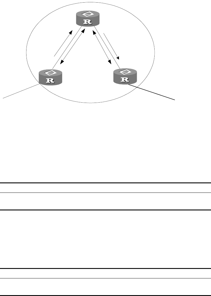
BGP 141
In the following figure, Router A receives an update packet from the external peer
and transmits it to Router C. Router C is a route reflector with two peer clients:
Router A and Router B.
Router C reflects the update packet from client Router A to client Router B. In this
configuration, the peer session between Router A and Router B is actually
eliminated because the route reflector will transfer the BGP information to Router
B.
Figure 12 Route Reflector Diagram
The reflector is the router that can complete the route reflection function. The
route reflector regards the IBGP peers as client and non-client. All peers that do
not belong to this cluster in the autonomous system are the non-clients. The
designation of route reflector and the addition of the client peer are implemented
with the peer reflect-client command.
Configuring the Route Reflection Between Clients
Perform the following configurations in BGP view..
By default, route reflection between clients is enabled.
Configuring the Cluster ID
Generally, there is only one route reflector in a cluster.
Perform the following configurations in BGP view..
By default, the router ID of the route reflector is used as the cluster ID.
Table 123 Configuring the Route Reflection Between Clients
Operation Command
Enable route reflection between clients reflect between-clients
Disable route reflection between clients undo reflect between-clients
Table 124 Configuring the Cluster ID
Operation Command
Configure the Cluster_ID of the route reflector reflector cluster-id { cluster-id | address }
Canceling the Cluster_ID of the route reflector undo reflector cluster-id
Router
EBGP
EBGP
Route reflector
Route reflected
Route updated
Router A Router B
Router C
Router
EBGP
EBGP
Route reflector
Route reflected
Route updated
Router A Router B
Router C

142 CHAPTER 5: IP ROUTING PROTOCOL OPERATION
Two Measures to Avoid Looping Inside an AS
As route reflector is imported, it is possible that path looping will be generated in
AS. Path update packets that already left the cluster may attempt to return to the
cluster. The conventional AS path method can not detect the internal AS looping,
because the path update packet has not left AS. Upon configuring route reflector,
BGP provides the following measures to avoid internal AS looping:
1Configure the Originator_ID of the route reflector
The Originator_ID is established by the route reflector. The originator drops the
update packet and returns it to the originator if it is an improper configuration.
The parameter is not necessarily configured, and it will automatically function after
BGP is enabled.
2 Configure the Cluster_ID of the route reflector
Configuring BGP AS Confederation Attributes
Confederation provides a method to handle the booming IBGP network
connections inside AS. It divides the AS into multiple sub-AS, in each, all IBGP
peers are fully connected, and are connected with other sub-AS of the
confederation.
The shortcomings of confederation: it is required that the route be re-configured
upon switching from non-confederation to confederation solution, and that the
logic topology be basically changed. Furthermore, the path selected via
confederation may not be the best path if there is no manually set BGP policy.
Configuring the Confederation ID
In the eye of the BGP speakers that are not part of the confederation, multiple
sub-AS’s that belong to the same confederation appear as a single unit. The
external network does not need to know the status of internal sub-AS’s, and the
confederation ID is the AS number identifying the confederation as a whole.
Perform the following configurations in BGP view..
By default, the confederation_ID is not configured.
Configure a Sub-AS Within the Confederation
Configure the confederation_ID first, and then configure the sub-AS that belongs
to the confederation. One confederation can include up to 32 sub-AS’s. The
AS-number that is used when configuring the sub-AS as part of the confederation
is valid within the confederation.
Perform the following configurations in BGP view..
Tab le 125 Configuring the Confederation ID
Operation Command
Configure confederation_ID confederation id as-number
Canceling confederation_ID undo confederation id
Tab le 126 Configuring a Sub-AS Belonging to the Confederation
Operation Command
Configure a confederation consisting of
sub-ASs
confederation peer-as as-number-1 [ ...
as-number-n ]

BGP 143
By default, no autonomous systems are configured as a member of the
confederation.
Configure the AS Confederation Nonstandard
If it is necessary to perform the interconnection with devices whose BGP
implementation confederation is different from that of RFC1965, you must
configure all the routers in the confederation.
Perform the following configurations in BGP view..
By default, the configured confederation is consistent with RFC1965.
Defining ACLs, AS Path List, and Route-policy
This section describes the configuration of ACL, AS path list, and Route-policy.
Defining the ACL See “Defining ACLs” on page 211
Defining the AS path list
The routing information packet of BGP includes an AS path domain. The AS
path-list can be used to match the autonomous system path domain of the BGP
routing information to filter the routing information which does not conform to
the requirements. For the same list number, the user can define multiple portions
of the AS path-list, i.e. a list number stands for a group of AS path ACLs. Each AS
path list is identified with a number.
Perform the following configurations in system view: .
By default, no AS path list is defined.
During the matching, the relationship of “OR” is available between the members
(acl-number) of the ACLs, so that when the routing information passes through
one piece of this group of lists, it means that the routing information has been
filtered by this group of as-path lists identified with this list number.
Defining Route-policy See “Defining Route-policy” on page 143.
Remove the specified sub-AS from the
confederation
undo confederation peer-as [ as-number-1 ]
[ ...as-number-n ]
Table 127 Configuring AS Confederation Attribute Compatible with Nonstandard
Operation Command
Configure AS confederation attribute
compatible with nonstandard router
confederation nonstandard
Cancel AS confederation attribute compatible
with nonstandard router
undo confederation nonstandard
Table 128 Defining the AS path list
Operation Command
Define the AS path list ip as-path-acl acl-number { permit | deny }
as-regular-expression
Delete the specified AS list undo ip as-path-acl acl-number
Table 126 Configuring a Sub-AS Belonging to the Confederation
Operation Command
144 CHAPTER 5: IP ROUTING PROTOCOL OPERATION
Defining Match Principle See “Defining If-match Clauses for a Route Policy”
on page 154.
Defining Evaluation Rules See “Defining Apply Clauses for a Route Policy” on
page 155.
Clearing the BGP Connection
After you change a BGP policy or protocol configuration, you must reset the
current BGP connection to enable the new configuration.
Perform the following configuration in user view.
Refreshing BGP Routes
When a BGP routing policy changes, the associated route information must be
recomputed.
Perform the following configuration in user view..
The import keyword means to refresh the routes learned from the peers and the
export keyword means to refresh routes advertised to the peers.
Displaying and Debugging BGP
After creating the configuration, execute the display command in any view to
display the BGP configuration, and to verify the effect of the configuration.
Execute the reset command in user view to clear the statistics of the
configuration. Execute the debugging command in user view to debug the
configuration. Execute the reset command in user view to reset the BGP statistic
information.
Tab le 129 Clearing the BGP Connection
Operation Command
Clear the connection between BGP and the
specified peers
reset bgp peer-address [ flap-info ]
Clear all connections of BGP reset bgp all
Clear the connections between the BGP and
all the members of a group
reset bgp group group-name
Tab le 130 Refreshing BGP Routes
Operation Command
Refreshing general BGP routes refresh bgp { all | peer-address | group
group-name } { import | export }
Tab le 131 Displaying and Debugging BGP
Operation Command
Display the routing information of the BGP display bgp routing-table [ ip-address [
mask ] ]
Display filtered AS path information in the
BGP
display ip as-path-acl acl-number
Display CIDR routes display bgp routing-table cidr
Display the routing information of the
specified BGP community
display bgp routing-table community [
aa:nn | no-export-subconfed | no-advertise
| no-export ]* [ whole-match ]
Display the routing information allowed by the
specified BGP community list
display bgp routing-table community-list
community-list-number [ whole-match ]

BGP 145
Typical BGP
Configuration Examples
Typical BGP Configuration Examples are described as follows:
■Configuring the BGP AS Confederation Attribute
■Configuring BGP Route Reflector
■Configuring BGP Routing
Configuring the BGP AS Confederation Attribute
Divide the following AS 100 into three sub-AS: 1001, 1002, and 1003, and
configure EBGP, confederation EBGP, and IBGP.
Display BGP dampened paths display bgp routing-table dampened
Display the routing information the specified
BGP peer advertised or received
display bgp routing-table peer
peer-address { advertised | received } [
network-address [ mask ] | statistic ]
Display the routes matching with the specified
access-list
display bgp routing-table as-path-acl
acl-number
Display route flapping statistics information display bgp routing-table flap-info [ {
regular-expression as-regular-expression } | {
as-path-acl acl-number } | { network-address [
mask [ longer-match ] ] } ]
View routes with different source ASs display bgp routing-table
different-origin-as
Display neighbors information display bgp peer peer-address verbose
display bgp peer [ verbose ]
Display the routing information that has been
configured
display bgp network
Display AS path information display bgp paths as-regular-expression
Display peer group information display bgp group [ group-name ]
Display the information on BGP routes which
is mapped to a certain regular expression
display bgp routing-table
regular-expression as-regular-expression
Display configured route-policy information display route-policy [ policy-name ]
Enable information debugging of all BGP
packets
debugging bgp all
Enable BGP event debugging debugging bgp event
Enable BGP Keepalive debugging debugging bgp keepalive [ receive | send ]
[ verbose ]
Enable BGP Open debugging debugging bgp open [ receive | send ] [
verbose ]
Enable BGP packet debugging debugging bgp packet [ receive | send ] [
verbose ]
Enable BGP Update packet debugging debugging bgp route-refresh [ receive |
send ] [ verbose ]
Enable information debugging of BGP normal
functions.
debugging bgp normal
Enable BGP Update packet debugging debugging bgp update [ receive | send ] [
verbose ]
Reset BGP flap information reset bgp flap-info [ regular-expression
as-regular-expression | as-path-acl
acl-number | network-address [ mask ] } ]
Table 131 Displaying and Debugging BGP
Operation Command
146 CHAPTER 5: IP ROUTING PROTOCOL OPERATION
Figure 13 AS Confederation Configuration
To configure the AS confederation:
1Configure Switch A:
[Switch A]bgp 1001
[Switch A-bgp]confederation id 100
[Switch A-bgp]confederation peer-as 1002 1003
[Switch A-bgp]group confed1002 external
[Switch A-bgp]peer confed1002 as-number 1002
[Switch A-bgp]group confed1003 external
[Switch A-bgp]peer confed1003 as-number 1003
[Switch A-bgp]peer 172.68.10.2 group confed1002
[Switch A-bgp]peer 172.68.10.3 group confed1003
2Configure Switch B:
[Switch B]bgp 1002
[Switch B-bgp]confederation id 100
[Switch B-bgp]confederation peer-as 1001 1003
[Switch B-bgp]group confed1001 external
[Switch B-bgp]peer confed1001 as-number 1001
[Switch B-bgp]group confed1003 external
[Switch B-bgp]peer confed1003 as-number 1003
[Switch B-bgp]peer 172.68.10.1 group confed1001
[Switch B-bgp]peer 172.68.10.3 group confed1003
3Configure Switch C:
[Switch C]bgp 1003
[Switch C-bgp]confederation id 100
[Switch C-bgp]confederation peer-as 1001 1002
[Switch C-bgp]group confed1001 external
[Switch C-bgp]peer confed1001 as-number 1001
[Switch C-bgp]group confed1002 external
[Switch C-bgp]peer confed1002 as-number 1002
[Switch C-bgp]peer 172.68.10.1 group confed1001
[Switch C-bgp]peer 172.68.10.2 group confed1002
[Switch C-bgp]group ebgp200 external
[Switch C-bgp]peer 156.10.1.2 group ebgp200 as-number 200
[Switch C-bgp]group ibgp1003 internal
[Switch C-bgp]peer 172.68.1.2 group ibgp1003
Configuring BGP Route Reflector
Switch B receives an update packet passing EBGP and transmits it to Switch C.
Switch C is a reflector with two clients: Switch B and Switch D. When Switch C
AS200
AS100
AS1002AS1001
AS1003
Ethernet
172.68.10.1 172.68.10.2
172.68.10.3
172.68.1.2
172.68.1.1
156.10.1.1
156.10.1.2
Switch A Switch B
Switch C Switch D
Switch E
BGP 147
receives a route update from Switch B, it will transmit such information to Switch
D. You must establish an IBGP connection between Switch B and Switch D,
because Switch C reflects information to Switch D.
Figure 14 BGP Route Reflector Configuration
1Configure Switch A:
[Switch A]interface vlan-interface 2
[Switch A-Vlan-interface2]ip address 192.1.1.1 255.255.255.0
[Switch A-Vlan-interface2]interface Vlan-interface 100
[Switch A-Vlan-interface100]ip address 1.1.1.1 255.0.0.0
[Switch A-Vlan-interface100]quit
[Switch A]bgp 100
[Switch A-bgp]network 1.0.0.0 255.0.0.0
[Switch A-bgp]group ex external
[Switch A-bgp]peer 192.1.1.2 group ex as-number 200
2Configure Switch B:
aConfigure VLAN 2:
[Switch B]interface Vlan-interface 2
[Switch B-Vlan-interface2]ip address 192.1.1.2 255.255.255.0
bConfigure VLAN 3:
[Switch B]interface Vlan-interface 3
[Switch B-Vlan-interface3]ip address 193.1.1.2 255.255.255.0
cConfigure peers.
[Switch B]bgp 200
[Switch B-bgp]group ex external
[Switch B-bgp]peer 192.1.1.1 group ex as-number 100
[Switch B-bgp]group in internal
[Switch B-bgp]peer 193.1.1.1 group in
3Configure Switch C:
aConfigure VLAN 3:
[Switch C]interface Vlan-interface 3
[Switch C-Vlan-interface3]ip address 193.1.1.1 255.255.255.0
bConfigure VLAN 4:
[Switch C]interface vlan-Interface 4
[Switch C-Vlan-interface4]ip address 194.1.1.1 255.255.255.0
cConfigure BGP peers and route reflector.
IBGP IBGP
EBGP
Client Client
Route reflector
VLAN 4
194.1.1.1/24
VLAN 3
193.1.1.1/24
VLAN 3
193.1.1.2/24
VLAN 4
194.1.1.2/24
VLAN 2
192.1.1.2/24
VLAN 2
192.1.1.1/24
AS100
AS200
Network
1.0.0.0
VLAN 100
1.1.1.1/8
Switch A Switch B
Switch C
Switch D
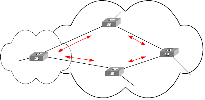
148 CHAPTER 5: IP ROUTING PROTOCOL OPERATION
[Switch C]bgp 200
[Switch C-bgp]group rr internal
[Switch C-bgp]peer rr reflect-client
[Switch C-bgp]peer 193.1.1.2 group rr
[Switch C-bgp]peer 194.1.1.2 group rr
4Configure Switch D:
aConfigure VLAN 4:
[Switch D]interface vlan-interface 4
[Switch D-Vlan-interface4]ip address 194.1.1.2 255.255.255.0
bConfigure BGP peers
[Switch D]bgp 200
group in internal
[Switch D-bgp]peer 194.1.1.1 group in
Using the display bgp routing-table command, you can view BGP routing table
on Switch B. Note that Switch B knows of the existence of network 1.0.0.0.
Using the display bgp routing-table command, you can view the BGP routing
table on Switch D. Note that Switch D also knows the existence of network
1.0.0.0.
Configuring BGP Routing
This example illustrates how the administrators manage the routing via BGP
attributes. All switches are configured with BGP, and IGP in AS 200 uses OSPF.
Switch A is in AS 100, and acts as Switch B of AS 200 and BGP neighbor of Switch
C. Both Switch B and Switch C operate IBGP to Switch D. Switch D is also in AS
200.
Figure 15 BGP Routing Configuration
1Configure Switch A:
[Switch A]interface Vlan-interface 2
[Switch A-Vlan-interface2]ip address 192.1.1.1 255.255.255.0
[Switch A]interface Vlan-interface 3
[Switch A-Vlan-interface3]ip address 193.1.1.1 255.255.255.0
aEnable BGP
[Switch A]bgp 100
VLAN 4
194.1.1.2/24
VLAN 2
192.1.1.1/24
VLAN 3
193.1.1.1/24 VLAN 3
193.1.1.2/24
VLAN 5
195.1.1.2/24
VLAN 2
192.1.1.2/24
2.2.2.2
4.4.4.4
3.3.3.3
1.1.1.1
AS100
AS200
VLAN 4
194.1.1.1/24
VLAN 5
195.1.1.1/24
IBGP
IBGP
EBGP
EBGP
To network
1.0.0.0
To network
2.0.0.0
To network
4.0.0.0
To network
3.0.0.0
Switch A
Switch B
Switch C
Switch D
BGP 149
bSpecify the network that BGP sends to
[Switch A-bgp]network 1.0.0.0
cConfigure the peers
[Switch A-bgp]group ex192 external
[Switch A-bgp]peer 192.1.1.2 group ex192 as-number 200
[Switch A-bgp]group ex193 external
[Switch A-bgp]peer 193.1.1.2 group ex193 as-number 200
[Switch A-bgp]quit
dConfigure the MED attribute of Switch A
■Add ACL on Switch A, enable network 1.0.0.0.
[Switch A]acl number 2000
[Switch A-acl-basic-2000]rule permit source 1.0.0.0 0.255.255.255
■Define two route policies, one is called apply_med_50 and the other is called
apply_med_100. The first MED attribute with the route policy as network
1.0.0.0 is set as 50, while the MED attribute of the second is 100.
[Switch A]route-policy apply_med_50 permit node 10
[Switch A-route-policy]if-match acl 2000
[Switch A-route-policy]apply cost 50
[Switch A-route-policy]quit
[Switch A]route-policy apply_med_100 permit node 10
[Switch A-route-policy]if-match acl 2000
[Switch A-route-policy]apply cost 100
[Switch A-route-policy]quit
■Apply route policy set_med_50 to egress route update of Switch C (193.1.1.2),
and apply route policy set_med_100 on the egress route of Switch B
(192.1.1.2)
[Switch A]bgp 100
[Switch A-bgp]peer ex193 route-policy apply_med_50 export
[Switch A-bgp]peer ex192 route-policy apply_med_100 export
2Configure Switch B:
[Switch B]interface vlan-interface 2
[Switch B-Vlan-interface2]ip address 192.1.1.2 255.255.255.0
[Switch B]interface vlan-interface 4
[Switch B-Vlan-interface4]ip address 194.1.1.2 255.255.255.0
[Switch B]ospf
[Switch B-ospf-1]area 0
[Switch B-ospf-1-area-0.0.0.0]network 194.1.1.0 0.0.0.255
[Switch B-ospf-1-area-0.0.0.0]network 192.1.1.0 0.0.0.255
[Switch B]bgp 200
[Switch B-bgp]undo synchronization
[Switch B-bgp]group ex external
[Switch B-bgp]peer 192.1.1.1 group ex as-number 100
[Switch B-bgp]group in internal
[Switch B-bgp]peer 194.1.1.1 group in
3Configure Switch C:
[Switch C]interface Vlan-interface 3
[Switch C-Vlan-interface3]ip address 193.1.1.2 255.255.255.0
[Switch C]interface vlan-interface 5
[Switch C-Vlan-interface5]ip address 195.1.1.2 255.255.255.0
[Switch C]ospf
150 CHAPTER 5: IP ROUTING PROTOCOL OPERATION
[Switch C-ospf-1]area 0
[Switch C-ospf-1-area-0.0.0.0]network 193.1.1.0 0.0.0.255
[Switch C-ospf-1-area-0.0.0.0]network 195.1.1.0 0.0.0.255
[Switch C]bgp 200
[Switch C-bgp]group ex external
[Switch C-bgp]peer 193.1.1.1 group ex as-number 100
[Switch C-bgp]group in internal
[Switch C-bgp]peer 195.1.1.1 group in
4Configure Switch D:
[Switch D]interface vlan-interface 4
[Switch D-Vlan-interface4]ip address 194.1.1.1 255.255.255.0
[Switch D]interface vlan-interface 5
[Switch D-Vlan-interface5]ip address 195.1.1.1 255.255.255.0
[Switch D]ospf
[Switch D-ospf-1]area 0
[Switch D-ospf-1-area-0.0.0.0]network 194.1.1.0 0.0.0.255
[Switch D-ospf-1-area-0.0.0.0]network 195.1.1.0 0.0.0.255
[Switch D-ospf-1-area-0.0.0.0]network 4.0.0.0 0.255.255.255
[Switch D]bgp 200
[Switch D-bgp]group ex external
[Switch D-bgp]peer ex as-number 200
[Switch D-bgp]peer 195.1.1.2 group ex
[Switch D-bgp]peer 194.1.1.2 group ex
To enable the configuration, all BGP neighbors will be reset using reset bgp all
command.
After above configuration, due to the fact that the MED attribute of route 1.0.0.0
discovered by Switch C is less than that of Switch B, Switch D will first select the
route 1.0.0.0 from Switch C.
If the MED attribute of Switch A is not configured, the local preference on Switch
C is configured as follows:
1Add ACL 2000 on Switch C and permit network 1.0.0.0
[Switch C]acl number 2000
[Switch C-acl-basic-2000]rule permit source 1.0.0.0 0.255.255.255
2Define the route policy with the name of localpref, of those, the local preference
matching ACL 2000 is set as 200, and that of not matching is set as 100:
[Switch C]route-policy localpref permit node 10
[Switch C-route-policy]if-match acl 2000
[Switch C-route-policy]apply local-preference 200
[Switch C-route-policy]route-policy localpref permit node 20
[Switch C-route-policy]apply local-preference 100
[Switch C-route-policy]quit
3Apply such route policy to the BGP neighbor 193.1.1.1 (Switch A)
[Switch C]bgp 200
[Switch C-bgp]peer 193.1.1.1 route-policy localpref import
By then, due to the fact that the Local preference attribute value (200)of the route
1.0.0.0 learned by Switch C is more than that of Switch B (Switch B is not
configured with local Preference attribute, 100 by default), Switch D will also first
select the route 1.0.0.0 from Switch C.

IP Routing Policy 151
Troubleshooting BGP The neighborhood cannot be established (the established state cannot be
entered).
The establishment of a BGP neighborhood requires that the router be able to
establish a TCP connection through port 179 and exchanges open packets
correctly. Do the following:
■Check whether the configuration of the neighbor's AS number is correct.
■Check whether the neighbor's IP address is correct.
■If the loopback interface is not being used, check whether the connect-source
loopback has been configured. By default, the router uses the optimal local
interface to establish the TCP connection, not using the loopback interface.
■If the EBGP neighbor is not directly connected, check whether the peer
ebgp-max-hop has been configured.
■Use the ping command to check whether the TCP connection is normal. Since
one router may have several interfaces able to reach the peer, the extended
ping -a ip-address command should be used to specify the source IP address
sending ping packet.
■If the ping operation fails, use the display ip routing-table command to
check if there is available route in the routing table to the neighbor.
If the ping operation succeeds, check if there is an ACL denying TCP port 179. If
the ACL is configured, cancel the denying of port 179.
The BGP route cannot be advertised correctly after importing route of IGP
with the command network.
Do the following:
The route that is imported by a command network should be same as a route in
the current routing table, and should include a destination segment and mask. A
route that covers a large network segment cannot be imported. For example,
route 10.1.1.0/24 can be imported, while 10.0.0.0/8 may cause an error.
IP Routing Policy When a router distributes or receives routing information, it needs to implement
some policies to filter the routing information so it can receive or distribute the
routing information that meets only the specified condition. A routing protocol
such as RIP may need to import routing information discovered by other protocols
to enrich its routing knowledge. While importing the routing information, it must
import only the information that meets its conditions.
To implement the routing policy, you must define a set of rules by specifying the
characteristics of the routing information to be filtered. You can set the rules
based on such attributes as destination address and source address of the
information. The rules can be set in advance and then used in the routing policy to
advertise, receive, and import the route information.
Configuring IP Routing Policy is described in the following sections:
■Routing Information Filters
■Configuring an IP Routing Policy
152 CHAPTER 5: IP ROUTING PROTOCOL OPERATION
■Troubleshooting Routing Policies
■Limiting Route Capacity
■Configuring Route Capacity
Routing Information
Filters
The Switch 8800 supports four kinds of filters, route-policy, acl, ip-prefix, and
community-list. The following sections introduce these filters:
■Route Policy
■ACL
■IP Prefix
■Community List
Route Policy
A route map is used for matching some attributes with given routing information
and the attributes of the information will be set if the conditions are satisfied.
A route map can include multiple nodes. Each node is a unit for match testing,
and the nodes are matched in a sequence-number-based order. Each node
includes a set of if-match and apply clauses. The if-match clauses define the
matching rules and the matching objects are attributes of routing information. The
comparison of if-match clauses for a node uses a series of Boolean and
statements. As a result, a match is found if all the matching conditions specified by
the if-match clauses are satisfied. The apply clause specifies the actions that are
performed after the node match test concerning the attribute settings of the route
information.
The comparison of different nodes in a route policy uses a Boolean or statement.
The system examines the nodes in the route policy in sequence. Once the route is
permitted by a single node in the route policy, the route passes the matching test
of the route policy without attempting the test of the next node.
ACL
The access control list (ACL) used by the route policy can be divided into three
types: advanced ACL, basic ACL, and Layer-2 ACL.
A basic ACL is usually used for routing information filtering. When the user
defines the ACL, the user defines the range of an IP address, subnet for the
destination network segment address, or the next-hop address of the routing
information. If an advanced ACL is used, perform the matching operation by the
specified source address range. Layer-2 ACLs
IP Prefix
The function of the ip-prefix is similar to that of the acl, but it is more flexible and
easier for users to understand. When the ip-prefix is applied to routing
information filtering, its matching objects are the destination address information,
and the domain of the routing information. In addition, in the ip-prefix, you can
specify the gateway options and require it to receive only the routing information
distributed by certain routers.

IP Routing Policy 153
An ip-prefix is identified by the ip-prefix name. Each ip-prefix can include multiple
list items, and each list item can specify the match range of the network prefix
forms, and is identified with a index-number. The index-number designates the
matching check sequence in the ip-prefix.
During the matching, the router checks list items identified by the
sequence-number in ascending order. Once a single list item meets the condition,
it means that it has passed the ip-prefix filtering and does not enter the testing of
the next list item.
Community List
The community list is only used in BGP. The routing information packet of BGP
includes a community attribute domain to identify a community. The community
list specifies the match condition target for the community attribute.
The definition of the community list is already implemented in the BGP
configuration.
Configuring an IP
Routing Policy
Configuring a routing policy includes tasks described in the following sections:
■Defining a Route Policy
■Defining If-match Clauses for a Route Policy
■Defining Apply Clauses for a Route Policy
■Importing Routing Information Discovered by Other Routing Protocols
■Defining IP Prefix
■Configuring for Filtering Received Routes
■Configuring for Filtering Distributed Routes
■Displaying and Debugging the Routing Policy
Defining a Route Policy
A route policy can include multiple nodes. Each node is a unit for the matching
operation. The nodes are tested again by sequence-number.
Perform the following configurations in system view.
The permit argument specifies that if a route satisfies all the if-match clauses of a
node, the route passes the filtering of the node, and the apply clauses for the
node are executed without taking the test of the next node. If a route does not
satisfy all the if-match clauses of a node, however, the route takes the test of the
next node.
The deny argument specifies that the apply clauses are not executed. If a route
satisfies all the if-match clauses of the node, the node denies the route and the
Table 132 Defining a Route Policy
Operation Command
Enter Route policy view route-policy route-policy-name { permit |
deny } node { node-number }
Remove the specified route-policy undo route-policy route-policy-name [
permit | deny | node node-number ]

154 CHAPTER 5: IP ROUTING PROTOCOL OPERATION
route does not take the test of the next node. If a route does not satisfy all the
if-match clauses of the node, however, the route takes the test of the next node.
The router tests the route against the nodes in the route policy in sequence, once
a node is matched, the route policy filtering is passed.
By default, the route policy is not defined.
If multiple nodes are defined in a route policy, at least one of them should be in
permit mode. Apply the route policy to filter routing information. If the routing
information does not match any node, the route policy denies the routing
information. If all the nodes in the route policy are in deny mode, all routing
information will be denied by the route policy.
Defining If-match Clauses for a Route Policy
The if-match clauses define the matching rules that the routing information must
satisfy to pass the route policy. The matching objects are attributes of the routing
information.
Perform the following configurations in route policy view.
Tab le 133 Defining If-match Conditions
Operation Command
Match the AS path domain of the BGP routing
information
if-match as-path acl-number
Cancel the matched AS path domain of the
BGP routing information
undo if-match as-path
Match the community attribute of the BGP
routing information
if-match community {
standard-community-number [ whole-match
] | extended-community-number }
Cancel the matched community attribute of
the BGP routing information
undo if-match community
Match the destination address of the routing
information
if-match { acl | ip-prefix }
Cancel the matched destination address of the
routing information set by the ACL
undo if-match [ acl acl-number | ip-prefix
ip-prefix-name ]
Match the next-hop interface of the routing
information
if-match interface { interface-type
interface-number }
Cancel the matched next-hop interface of the
routing information
undo if-match interface
Match the next-hop of the routing
information
if-match ip next-hop { acl acl-number |
ip-prefix ip-prefix-name }
Cancel the matched next-hop of the routing
information set by the address prefix list
undo if-match ip next-hop [ip-prefix
ip-prefix-name ]
Match the routing cost of the routing
information
if-match cost cost
Cancel the matched routing cost of the
routing information
undo if-match cost
Match the tag domain of the OSPF routing
information
if-match tag value
Cancel the tag domain of the matched OSPF
routing information
undo if-match tag

IP Routing Policy 155
By default, no matching is performed.
The if-match clauses for a node in the route policy require that the route satisfy
all the clauses to match the node before the actions specified by the apply clauses
can be executed.
If no if-match clauses are specified, all the routes pass the filtering on the node.
Defining Apply Clauses for a Route Policy
The apply clauses specify actions, which are the configuration commands
executed after a route satisfies the filtering conditions that are specified in the
if-match clauses. In this way, some attributes of the route can be modified.
Perform the following configurations in Route policy view.
By default, no apply clauses are defined.
Table 134 Defining Apply Clauses
Operation Command
Modify an AS path for BGP routes. apply as-path as-number-1 [ as-number-2 [
as-number-3 ... ] ]
Cancel modification of an AS path for BGP
routes.
undo apply as-path
Set the community attribute in the BGP
routing information
apply community { [ { aa:nn |
no-export-subconfed | no-advertise |
no-export ]... } | [ additive | none ]
Cancel the set community attribute in the BGP
routing information
undo apply community
Set the next-hop address of the routing
information
apply ip next-hop { ip-address [ ip-address ] |
acl acl-number }
Cancel the next-hop address of the routing
information
undo apply ip next-hop
Import the route to IS-IS Level 1, Level 2, or
Level 1-2
apply isis [ level-1 | level-2 | level-1-2 ]
Remove the function of importing the route to
IS-IS
undo apply isis
Set the local preference of the BGP routing
information
apply local-preference localpref
Cancel the local preference of the BGP routing
information
undo apply local-preference
Set the routing cost of the routing information apply cost value
Cancel the routing cost of the routing
information
undo apply cost
Set the cost type of the routing information apply cost-type [ internal | external ]
Remove the setting of the cost type undo apply cost-type
Set the route origin of the BGP routing
information
apply origin { igp | egp as-number |
incomplete }
Cancel the route origin of the BGP routing
information
undo apply origin
Set the tag domain of the OSPF routing
information
apply tag value
Cancel the tag domain of the OSPF routing
information
undo apply tag

156 CHAPTER 5: IP ROUTING PROTOCOL OPERATION
If the routing information meets the match conditions specified in the route policy
and also notifies the MED value configured with apply cost-type internal when
notifying the IGP route to the EBGP peers, then this value is regarded as the MED
value of the IGP route. The preference configured with the apply cost-type
internal is lower than the preference that is configured with the apply cost
command, but higher than the preference that is configured with the default
med command.
Importing Routing Information Discovered by Other Routing Protocols
A routing protocol can import the routes that are discovered by other routing
protocols to enrich its route information. The route policy can filter route
information to implement the redistribution. If the destination routing protocol
that imports the routes cannot directly reference the route costs of the source
routing protocol, you should satisfy the requirement of the destination protocol by
specifying a route cost for the imported route.
Perform the following configuration in routing protocol view.
By default, the routes discovered by other protocols are not imported.
In different routing protocol views, the parameter options are different. For
details, refer to the description of the import-route command for each protocol .
Defining IP Prefix
A prefix list is identified by the IP prefix name. Each IP prefix can include multiple
items, and each item can specify the matching range of the network prefix forms.
The index-number specifies the matching sequence in the prefix list.
Perform the following configurations in system view.
During the matching, the router checks list items identified by the index-number in
the ascending order. If only one list item meets the condition, it means that it has
passed the ip-prefix filtering (and does not enter the testing of the next list item).
If more than one IP prefix item is defined, then the match mode of at least one list
item should be the permit mode. The list items of the deny mode can be defined
to rapidly filter the routing information not satisfying the requirement, but if all
Tab le 135 Configuring Importing Routes of Other Protocols
Operation Command
Import routes of other protocols import-route protocol [ med med | cost cost
] [ tag value ] [ type 1 | 2 ] [ route-policy
route-policy-name ]
Do not import routes of other protocols undo import-route protocol
Tab le 136 Defining Prefix-list
Operation Command
Define a prefix list ip ip-prefix ip-prefix-name [ index
index-number ] { permit | deny } network len
[ greater-equal greater-equal ] [ less-equal
less-equal ]
Remove a prefix list undo ip ip-prefix ip-prefix-name [ index
index-number | permit | deny ]

IP Routing Policy 157
the items are in the deny mode, no route will pass the ip-prefix filtering. You can
define an item of permit 0.0.0.0/0 greater-equal 0 less-equal 32 after the
multiple list items in the deny mode to let all the other routes pass.
Configuring for Filtering Received Routes
Perform the following configuration in routing protocol view.
Define a policy that filters the routing information that does not satisfy the
conditions and receives routes with the help of an ACL or address prefix-list. The
filter-policy gateway command specifies that only the update packets from a
specific neighboring router will be received.
Configuring for Filtering Distributed Routes
Define a policy concerning route distribution that filters the routing information
that does not satisfy the conditions, and distributes routes with the help of an ACL
or address ip-prefix.
Perform the following configuration in routing protocol view.
The route policy supports importing the routes discovered by the following
protocols into the routing table:
■Direct: The hop (or host) to which the local interface is directly connected.
■Static: Static Route Configuration
■RIP: Route discovered by RIP
■OSPF: Route discovered by OSPF
■OSPF-ASE: External route discovered by OSPF
■OSPF-NSSA: NSSA route discovered by OSPF
■BGP: Route acquired by BGP
Table 137 Configuring Filtering for Received Routes
Operation Command
Configure to filter the received routing
information distributed by the specified
address
filter-policy gateway ip-prefix-name import
Cancel the filtering of the received routing
information distributed by the specified
address
undo filter-policy gateway ip-prefix-name
import
Configure to filter the received global routing
information
filter-policy { acl-number | ip-prefix
ip-prefix-name } [ gateway ] import
Cancel the filtering of the received global
routing information
undo filter-policy { acl-number | ip-prefix
ip-prefix-name } [ gateway ] import
Table 138 Configuring Filtering of Distributed Routes
Operation Command
Configure to filter the routes distributed by
the protocol
filter-policy { acl-number | ip-prefix
ip-prefix-name } export [ routing-process ]
Cancel the filtering of the routes distributed
by the protocol
undo filter-policy { acl-number | ip-prefix
ip-prefix-name } export [ routing-process ]
158 CHAPTER 5: IP ROUTING PROTOCOL OPERATION
If routing-process is BGP, you should also specify the process number or AS
number.
By default, the filtering of the received and distributed routes will not be
performed.
Displaying and Debugging the Routing Policy
Execute display command in all views to display the operation of the routing
policy configuration, and to verify the effect of the configuration.
Example: Configuring to
Filter the Received
Routing Information
■Switch A communicates with Switch B, running the OSPF protocol.
■Redistribute three static routes through configuring the OSPF routing process
on the Switch A.
■The route filtering rules can be configured on Switch B to make the received
three static routes partially visible and partially shielded. It means that routes in
the network segments 20.0.0.0 and 40.0.0.0 are visible while those in the
network segment 30.0.0.0 are shielded.
Figure 16 Filtering Received Routing Information
Configure Switch A:
1Configure the IP address of VLAN interface.
[Switch A]interface vlan-interface 100
[Switch A-Vlan-interface100]ip address 10.0.0.1 255.0.0.0
[Switch A]interface vlan-interface 200
[Switch A-Vlan-interface200]ip address 12.0.0.1 255.0.0.0
2Configure three static routes.
[Switch A]ip route-static 20.0.0.1 255.255.255.255 12.0.0.1
[Switch A]ip route-static 30.0.0.1 255.255.255.255 12.0.0.1
[Switch A]ip route-static 40.0.0.1 255.255.255.255 12.0.0.1
3Enable OSPF protocol and specifies the number of the area to which the interface
belongs.
[Switch A]router id 1.1.1.1
[Switch A]ospf
[Switch A-ospf]area 0
[Switch A-ospf-area-0.0.0.0]network 10.0.0.0 0.0.0.255
Tab le 139 Displaying and Debugging the Route Policy
Operation Command
Display the routing policy display route-policy [ route-policy-name ]
Display the path information of the AS filter in
BGP
display ip as-path-acl [ acl-number ]
Display the address prefix list information display ip ip-prefix [ ip-prefix-name ]
static 20.0.0.1/8
30.0.0.1/8
40.0.0.1/8
1.1.1.1
Switch A Switch B
2.2.2.2
area 0

Route Capacity 159
4Import the static routes
[Switch A-ospf]import-route static
Configure Switch B:
1Configure the IP address of VLAN interface.
[Switch B]interface vlan-interface 100
[Switch B-Vlan-interface100]ip address 10.0.0.2 255.0.0.0
2Configure the access control list.
[Switch B]acl number 2000
[Switch B-acl-basic-2000]rule deny source 30.0.0.0 0.255.255.255
[Switch B-acl-basic-2000]rule permit source any
3Enable OSPF protocol and specifies the number of the area to which the interface
belongs.
[Switch B]router id 2.2.2.2
[Switch B]ospf
[Switch B-ospf]area 0
[Switch B-ospf-area-0.0.0.0]network 10.0.0.0 0.0.0.255
4Configure OSPF to filter the external routes received.
[Switch B-ospf]filter-policy 2000 import
Troubleshooting Routing
Policies
Routing information filtering cannot be implemented in normal operation of the
routing protocol
Check for the following faults:
■The if-match mode of at least one node of the Route policy should be the
permit mode. When a Route-policy is used for the routing information
filtering, if a piece of routing information does not pass the filtering of any
node, then it means that the route information does not pass the filtering of
the Route-policy. When all the nodes of the Route-policy are in the deny
mode, then all the routing information cannot pass the filtering of the
Route-policy.
■The if-match mode of at least one list item of the ip-prefix should be the
permit mode. The list items of the deny mode can be defined to rapidly filter
the routing information not satisfying the requirement, but if all the items are
in the deny mode, no routes will pass the ip-prefix filtering. You can define an
item of permit 0.0.0.0/0 less-equal 32 after the multiple list items in the deny
mode, so as to let all the other routes pass the filtering (If less-equal 32 is not
specified, only the default route will be matched).
Route Capacity In practical networking applications, there is always a large number of routes in
the routing table, especially OSPF routes and BGP routes. The routing information
is usually stored in the memory of the switch. When the size of the routing table
increases, it can consume a significant amount of switch’s memory.
To solve this problem, Switch 8800 switches provide a mechanism to control the
size of the routing table. They monitor the free memory in the system to
determine whether to add new routes to the routing table, and whether or not to
keep connection with a routing protocol.

160 CHAPTER 5: IP ROUTING PROTOCOL OPERATION
The default value normally meets the network requirements. You should be
careful when modifying the configuration to avoid reducing the stability of the
network.
Limiting Route Capacity The size of the routing table is determined by BGP and OSPF routes. Therefore, the
route capacity limitation of the Switch 8800 is only effective for these two types of
routes and has no impact on static routes and other dynamic routing protocols.
When the free memory of a Switch 8800 reduces to the lower limit value, the
system will disconnect BGP and OSPF and remove their routes from the routing
table to release memory. The system checks the free memory periodically. When
enough free memory is detected to restore the safety value, BGP and OSPF
connection is restored.
Configuring Route
Capacity
Route capacity configuration includes tasks described in the following sections:
■Setting the Lower Limit and the Safety Value Simultaneously
■Enabling and Preventing Automatic Recovery of Disconnected Routing
Protocols
■Displaying and Debugging Route Capacity
Setting the Lower Limit and the Safety Value Simultaneously
When you need to modify both the lower limit and the safety value of the switch
memory, you can (and are recommended to) simultaneously modify the two
configurations.
You can also restore the lower limit and the safety value of the switch memory to
the default value at the same time if it is necessary.
Perform the following configuration in the system view.
The default values of the lower limit and the safety value of the switch memory are
2Mbytes and 4Mbytes, respectively.
Note that safety-value must have a higher value than limit-value.
Enabling and Preventing Automatic Recovery of Disconnected Routing
Protocols
If the automatic memory restoration function of a switch is disabled, connection
of routing protocols will not be restored even if the free memory returns to the
safety value.
Tab le 140 Setting the Lower Limit and the Safety Value of the Switch Memory
Simultaneously
Operation Command
Set the lower limit and the safety value of the
switch memory simultaneously
memory safety safety-value limit limit-value
Restore the lower limit and the safety value of
the switch memory to the default value
undo memory [ safety | limit ]

Route Capacity 161
Perform the following configurations in system view.
By default, memory automatic restoration function of a switch is enabled.
Displaying and Debugging Route Capacity
Execute the display command in all views to display the route capacity
configuration.
Table 141 Enabling and Preventing Automatic Recovery of Disconnected Routing
Protocols
Operation Command
Enable automatic recovery of disconnected
routing protocols
memory auto-establish enable
Prevent automatic recovery of disconnected
routing protocols
memory auto-establish disable
Table 142 Displaying and Debugging Route Capacity
Operation Command
Display the route capacity related memory
information
display memory [ slot slot-number ]
Display the route capacity related memory
setting and state information
display memory limit
162 CHAPTER 5: IP ROUTING PROTOCOL OPERATION
Route Capacity 163
164 CHAPTER 5: IP ROUTING PROTOCOL OPERATION
Route Capacity 165

166 CHAPTER 5: IP ROUTING PROTOCOL OPERATION

6MULTICAST PROTOCOL
This chapter includes information on the following:
■IP Multicast Overview
■Configuring Common Multicast
■Configuring IGMP
■IGMP Snooping
■Configuring PIM-DM
■Configuring PIM-SM
■GMRP
IP Multicast Overview Many transmission methods can be used when the destination (including data,
voice and video) is the secondary use of the network. If the multicast method is
used, you should establish an independent data transmission path for each user.
The broadcast mode can be used if you intend to send the information to all users
on the network. In either case, the end users will receive the information. For
example, if the same information is required by 200 users on the network, the
traditional solution is to send the information 200 times in unicast mode. In the
broadcast mode, the data is broadcast over the entire network. However, both of
the methods waste bandwidth resources. In addition, the broadcast mode cannot
ensure information security.
IP multicast technology solves this problem. The multicast source sends the
information only once. Multicast routing protocols establish tree-type routing for
multicast packets. The information being sent will be replicated and distributed as
far as possible (see Figure 1). Therefore, the information can be correctly sent, with
high efficiency, to each user.
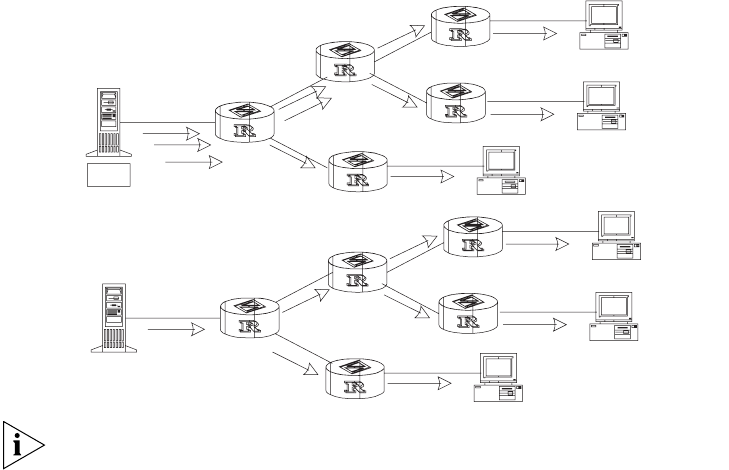
168 CHAPTER 6: MULTICAST PROTOCOL
Figure 1 Comparison Between the Unicast and Multicast Transmission
A multicast source does not necessarily belong to a multicast group. It only sends
data to the multicast group and it is not necessarily a receiver. Multiple sources can
send packets to a multicast group simultaneously.
A router that does not support multicast may exist on the network. A multicast
router can encapsulate multicast packets in unicast IP packets by tunneling and
sending them on to the neighboring multicast router. The neighboring multicast
router removes the unicast IP header and continues the multicast transmission.
Multicast advantages:
■Enhanced efficiency by reducing network traffic and relieving server and CPU
loads.
■Optimized performance decreases traffic redundancy.
■Distributed applications make multipoint applications possible.
Configuring an IP Multicast Overview is described in the following sections:
■Multicast Addresses
■IP Multicast Protocols
■Forwarding IP Multicast Packets
■Applying Multicast
Multicast Addresses The destination addresses of multicast packets use Class D IP addresses ranging
from 224.0.0.0 to 239.255.255.255. Class D addresses cannot appear in the
source IP address fields of IP packets.
During unicast data transmission, a packet is transmitted from the source address
to the destination address with the “hop-by-hop” principle of the IP network. A
packet has more than one destination address in a multi-cast environment, i.e., a
group of addresses. All the information receivers join a group. Once a receiver
joins the group, data flowing to the group is sent to the receiver immediately. All
members in the group can receive the packets. Membership of a multicast group is
dynamic, that is, hosts can join and leave groups at any time.
Unicast
Multicast
Server
Server
Receiver
Receiver
Receiver
Receiver
Receiver
Receiver

IP Multicast Overview 169
A multicast group can be either permanent or temporary. Part of addresses in the
multicast group are reserved by the IANA and are known as the permanent
multicast group. IP addresses of a permanent group are unchanged, but the
members in the group can change. The number of members in a permanent
multicast group can be random or even 0. Those IP multicast addresses that are
not reserved for permanent multicast groups can be used by temporary groups.
Ranges and meanings of Class D addresses are shown in Table 1.
Reserved multicast addresses that are commonly used are shown Table 2:
Ethernet Multicast MAC Addresses
When unicast IP packets are transmitted in Ethernet, the destination MAC address
is the MAC address of the receiver. However, when multicast packets are
Table 1 Ranges and Meanings of Class D Addresses
Class D address range Meaning
224.0.0.0∼224.0.0.255 Reserved multicast addresses (addresses of
permanent groups). Address 224.0.0.0 is
reserved. The other addresses can be used by
routing protocols.
224.0.1.0∼238.255.255.255 Multicast addresses available for users
(addresses of temporary groups). They are
valid in the entire network.
239.0.0.0∼239.255.255.255 Multicast addresses for local management.
They are valid only in the specified local range.
Table 2 Reserved Multicast Address List
Class D address Meaning
224.0.0.0 Base Address (Reserved)
224.0.0.1 Addresses of all hosts
224.0.0.2 Addresses of all multicast routers
224.0.0.3 Unassigned
224.0.0.4 DVMRP routers
224.0.0.5 OSPF routers
224.0.0.6 OSPF DR (designated router)
224.0.0.7 ST routers
224.0.0.8 ST hosts
224.0.0.9 RIP-2 routers
224.0.0.10 IGRP routers
224.0.0.11 Mobile agents
224.0.0.12 DHCP server/Relay agent
224.0.0.13 All PIM routers
224.0.0.14 RSVP encapsulation
224.0.0.15 All CBT routers
224.0.0.16 Designated SBM
224.0.0.17 All SBMS
224.0.0.18 VRRP
…… ……
170 CHAPTER 6: MULTICAST PROTOCOL
transmitted, the destination is no longer a specific receiver but a group with
unspecific members. Therefore, the multicast MAC address should be used.
Multicast MAC addresses correspond to multicast IP addresses. IANA (Internet
Assigned Number Authority) stipulates that the higher 24 bits of the multicast
MAC address is 0x01005e and the lower 23 bits of the MAC address is the lower
23 bits of the multicast IP address.
Figure 2 Mapping Between the Multicast IP Address and the Ethernet MAC Address
Only 23 bits of the last 28 bits in the IP multicast address is mapped to the MAC
address. Therefore the 32 IP multicast addresses are mapped to the same MAC
address.
IP Multicast Protocols Multicast uses the multicast group management protocol, and the multicast
routing protocol. The multicast group management protocol uses Internet Group
Management Protocol (IGMP) as the IP multicast basic signaling protocol. It is used
between hosts and routers and enables routers to determine if members of the
multicast group are on the network segment. The multicast routing protocol is
used between multicast routers and creates and maintains multicast routes, and
allows high-efficient multicast packet forwarding. At present, multicast routing
protocols mainly include PIM-SM, PIM-DM.
Tasks for configuring IP Multicast Protocols are described in the following sections:
■Internet Group Management Protocol (IGMP)
■Multicast Routing Protocol
Internet Group Management Protocol (IGMP)
Internet Group Management Protocol (IGMP) is the only protocol that hosts can
use. It defines the membership establishment and maintenance mechanism
between hosts and routers, and is the basis of the entire IP multicast. Hosts report
the group membership to a router through IGMP and inform the router of the
conditions of other members in the group through the directly connected host.
If a user on the network joins a multicast group through IGMP declaration, the
multicast router on the network will transmit the information sent to the multicast
group through the multicast routing protocol. Finally, the network will be added to
the multicast tree as a branch. When the host, as a member of a multicast group,
begins receiving the information, the router queries the group periodically to
check whether members in the group are involved. As long as one host is involved,
the router receives data. When all users on the network quit the multicast group,
the related branches are removed from the multicast tree.
Multicast Routing Protocol
A multicast group address has a virtual address. Unicast allows packets to be
routed from the data source to the specified destination address. This is not
48-bit MAC
address
32-bit IP
address 5 bits
not
mapped
Lower 23 bits directly mapped
IP Multicast Overview 171
possible for multicast. The multicast application sends the packets to a group of
receivers (as with multicast addresses) who are ready to receive the data but not
only to one receiver (as with unicast address).
The multicast routing creates a loop-free data transmission path from one data
source to multiple receivers. The task of the multicast routing protocol is to create
a distribution tree architecture. A multicast router can use multiple methods to
build up a path for data transmission, i.e., the distribution tree.
■PIM-DM (Protocol-Independent Multicast Dense Mode, PIM-DM)
PIM dense mode is suitable for small networks. It assumes that each subnet in
the network contains at least one receiver who is interested in the multicast
source. Multicast packets are flooded to all points of the network. Subsequent
resources (such as bandwidth and CPU of routers) are consumed. In order to
decrease the consumption of these precious network resources, branches that
do not have members send Prune messages toward the source to reduce the
unwanted/unnecessary traffic. To enable the receivers to receive multicast data
streams, the pruned branches can be restored periodically to a forwarding
state. To reduce latency time, the PIM dense mode uses the prune mechanism
to actively restore multicast packet forwarding. The periodical flood and prune
are characteristics of PIM dense mode. Generally, the forwarding path in dense
mode is a “source tree” rooted at the source with multicast members as the
branches. Since the source tree uses the shortest path from the multicast
source and the receiver, it is also called the shortest path tree (SPT).
■PIM-SM (Protocol-Independent Multicast Sparse Mode, PIM-SM)
Dense mode uses the flood-prune technology, which is not applicable for
WAN. In WAN, multicast receivers are sparse and therefore the sparse mode is
used. In sparse mode, hosts need not receive multicast packets unless, by
default, there is an explicit request for the packets. A multicast router must
send a join message to the RP (Rendez-vous Point, which needs to be built into
the network and is a virtual place for data exchange) corresponding to the
group for receiving the multicast data traffic from the specified group. The join
message passes routers and finally reaches the root, i.e., the RP. The join
message becomes a branch of the shared tree. In PIM sparse mode, multicast
packets are sent to the RP first, and then are forwarded along the shared tree
rooted at the RP and with members as the branches. To prevent the branches
of the shared tree from being deleted, PIM sparse mode sends join messages to
branches periodically to maintain the multicast distribution tree.
To send data to the specified address, senders register with the RP first before
forwarding data to the RP. When the data reaches the RP, the multicast packets
are replicated and sent to receivers along the path of the distribution tree.
Replication only happens at the branches of the distribution tree. This process
can be repeated automatically until the packets reach the destination.
Forwarding IP Multicast
Packets
In the multicast model, the source host sends information to the host group
represented by the multicast group address within the destination address fields of
the IP packets. The multicast model must forward multicast packets to multiple
external interfaces so that the packets can be forwarded to all receivers.
■RPF (Reverse Path Forwarding)
To ensure that a multicast packet reaches the router along the shortest path,
the multicast must depend on the unicast routing table or a unicast routing

172 CHAPTER 6: MULTICAST PROTOCOL
table independently provided for multicast (such as the MBGP multicast routing
table). This check mechanism is the basis for most multicast routing protocols ,
which is known as a RPF (Reverse Path Forwarding) check. A multicast router
uses the source address from the multicast packet to query the unicast routing
table, or the independent multicast routing table, to determine the incoming
interface at which the packet arrives. If a source tree is used, the source address
is the address of the source host sending the multicast packet. If a shared tree
is used, the source address is the address of the root of the shared tree. When
a multicast packet arrives at the router, if RPF check succeeds, the packet will
be forwarded according to the multicast forwarding entry. Otherwise, the
packet will be dropped.
Applying Multicast IP multicast technology effectively solves the problem of packet forwarding from
single-point to multi-point. It implements high-efficient data transmission from
single-point to multi-point in IP networks and can save a large amount of network
bandwidth and reduce network loads. New value-added services that use
multicast can be delivered, including direct broadcasting, Web TV, distance
learning, distance medicine, net broadcasting station and real-time audio/video
conferencing.
■Multimedia and streaming media applications
■Communications of the training and corporate sites
■Data repository and finance (stock) applications
■Any “point-to-multi-point” data distribution
With the increase of multimedia services on IP networks, multicast has huge
market potential.
Configuring Common
Multicast
A common multicast configuration covers both the multicast group management
protocol and the multicast routing protocol. The configuration includes enabling
multicast, configuring multicast forwarding boundary, and displaying multicast
routing table and multicast forwarding table.
Configuring Common
Multicast
Common multicast configuration includes:
■Enabling Multicast
■Configuring the Multicast Route Limit
■Clearing MFC Forwarding Entries or Statistic Information
■Clearing Route Entries From the Core Multicast Routing Table
■Displaying and Debugging Common Multicast Configuration
Enabling Multicast
Enable multicast first before enabling the multicast routing protocol.
Perform the following configuration in system view.
Tab le 3 Enabling Multicast
Operation Command
Enable multicast multicast routing-enable

Configuring Common Multicast 173
By default, multicast routing is disabled.
Only when multicast is enabled can another multicast configuration be used.
Configuring the Multicast Route Limit
If the existing route entries exceed the capacity value you configured when using
this command, the system will not delete the existing entries, but displays the
message, “Existing route entries exceed the configured capacity value”.
Perform the following configuration in system view.
By default, the multicast route-limit is 256.
Clearing MFC Forwarding Entries or Statistic Information
You can clear the multicast forwarding cache (MFC) forward entries or statistical
information of FMC forward entries using the reset multicast forwarding-table
command.
Perform the following configuration in user view.
Clearing Route Entries From the Core Multicast Routing Table
You can clear route entries from the core multicast routing table, as well as MFC
forwarding entries using the reset multicast routing-table command.
Perform the following configuration in user view.
Disable multicast undo multicast routing-enable
Table 4 Configure the Multicast Route Limit
Operation Command
Configure multicast route limit multicast route-limit limit
Restore multicast route limit to the
default value
undo multicast route-limit
Table 5 Clear MFC Forwarding Entries or Statistic Information
Operation Command
Clear MFC forwarding entries
or its statistic information
reset multicast forwarding-table [ statistics ] { all | {
group-address [ mask { group-mask | group-mask-length } ] |
source-address [ mask { source-mask | source-mask-length } ] |
incoming-interface interface-type interface-number } * }
Table 6 Clear Routing Entries of Multicast Routing Table
Operation Command
Clear routing entries of multicast routing table reset multicast routing-table { all | {
group-address [ mask { group-mask |
group-mask-length } ] | source-address [ mask
{ source-mask | source-mask-length } ] | {
incoming-interface interface-type
interface-number } } * }
Table 3 Enabling Multicast
Operation Command

174 CHAPTER 6: MULTICAST PROTOCOL
Displaying and Debugging Common Multicast Configuration
After the previous configurations, execute the display command to view the
multicast configuration, and to verify the configuration.
Execute the debugging command in user view to debug multicast.
Configuring IGMP IGMP (Internet Group Management Protocol) is a protocol, in the TCP/IP suite,
responsible for management of IP multicast members. It is used to establish and
maintain multicast membership among IP hosts and their connected neighboring
routers. IGMP excludes transmitting and maintenance information among
multicast routers, which are completed by multicast routing protocols. All hosts
participating in multicast must implement IGMP.
Hosts participating in multicast can join or leave a multicast group at any time, in
any place, and without limitation of member numbers. A multicast router does not
need and cannot keep the membership of all hosts. It only uses IGMP to learn
whether receivers (i.e., group members) of a multicast group are present on the
subnet connected to each interface. A host only needs to keep the multicast
groups it has joined.
IGMP is not symmetric on hosts and routers. Hosts need to respond to IGMP query
messages from the multicast router, i.e., report the group membership to the
router. The router needs to send membership query messages periodically to
discover whether hosts join the specified group on its subnets according to the
received response messages. When the router receives the report that hosts leave
the group, the router will send a group-specific query (IGMP Version 2) to discover
whether there are no members in the group.
Up to now, IGMP has three versions, IGMP Version 1 (defined by RFC1112), IGMP
Version 2 (defined by RFC2236) and IGMP Version 3. IGMP Version 2 is, now, the
most widely used version.
Tab le 7 Display and Debug Common Multicast Configuration
Operation Command
Display the multicast routing table display multicast routing-table [
group-address [ mask { mask | mask-length } ]
| source-address [ mask { mask | mask-length }
] | incoming-interface { interface-type
interface-number | register } ]*
Display the multicast forwarding table display multicast forwarding-table [
group-address [ mask { mask | mask-length } ]
| source-address [ mask { mask | mask-length }
] | incoming-interface register } ]*
Display the RPF routing information display multicast rpf-info source-address
Enable multicast packet forwarding
debugging
debugging multicast forwarding
Disable multicast packet forwarding
debugging
undo debugging multicast forwarding
Enable multicast forwarding status debugging debugging multicast-status forwarding
Disable multicast forwarding status debugging undo debugging multicast-status forwarding
Enable multicast kernel routing debugging debugging multicast kernel-routing
Disable multicast kernel routing debugging undo debugging multicast kernel-routing
Configuring IGMP 175
IGMP Version 2 boasts the following improvements over IGMP Version 1:
■Election mechanism of multicast routers on the shared network segment
A shared network segment means that there are multiple multicast routers on
a network segment. In this case, all routers running IGMP on the network
segment can receive the membership report from hosts. Therefore, only one
router is required to send membership query messages. In this case, the router
election mechanism is required to specify a router as the querier.
In IGMP Version 1, selection of the querier is determined by the multicast
routing protocol. IGMP Version 2 specifies that the multicast router with the
lowest IP address is elected as the querier when there are multiple multicast
routers on the same network segment.
■Leaving group mechanism
In IGMP Version 1, hosts leave the multicast group quietly without informing
the multicast router. The multicast router can only depend on the timeout of
the response time to confirm when hosts leave the group. In Version 2, when a
host leaves a multicast group, it will send a leave group message.
■Specific group query
In IGMP Version 1, a query of multicast routers is targeted at all the multicast
groups on the network segment. This is known as General Query.
In IGMP Version 2, besides general query, Group-Specific Query is added. The
destination IP address of the query packet is the IP address of the multicast
group. The group address domain in the packet is also the IP address of the
multicast group. This prevents the hosts of members of other multicast groups
from sending response messages.
■Max response time
The Max Response Time is added in IGMP Version 2. It is used to dynamically
adjust the allowed maximum time for a host to respond to the membership
query message.
Configuring IGMP Once multicast is enabled, IGMP will automatically run on each interface.
Generally, IGMP does not need to be configured. In the following configuration,
only the first one is mandatory.
Basic IGMP configuration includes:
■Enabling Multicast
■Enabling IGMP on an Interface
Advanced IGMP configuration includes:
■Configuring the IGMP Version
■Configuring the Interval for Sending the IGMP Group-Specific Query Packet
■Configuring the Interval for Sending IGMP Group-Specific Query Packet
■Configuring the Limit of IGMP Groups on an Interface
■Configuring a Router to be a Member of a Group
■Limiting Access to IP Multicast Groups
■Configuring the IGMP Query Message Interval

176 CHAPTER 6: MULTICAST PROTOCOL
■Configuring the IGMP Querier Present Timer
■Configuring the Maximum Query Response Time
■Deleting IGMP Groups Joined on an Interface
■Displaying and Debugging IGMP
Enabling Multicast
After multicast is enabled, IGMP will automatically run on all interfaces.
For details, see “Configuring Common Multicast ” on page 172.
Enabling IGMP on an Interface
You must enable multicast before you can execute the igmp enable command.
After this, you can initiate the IGMP feature configuration.
Perform the following configuration in VLAN interface view.
By default, IGMP is not enabled.
Configuring the IGMP Version
Perform the following configuration in VLAN interface view.
The default is IGMP Version 2.
All routers on a subnet must support the same version of IGMP. After detecting
the presence of IGMP Version 1 system, a router cannot automatically switch to
Version 1.
Configuring the Interval for Sending the IGMP Group-Specific Query
Packet
In the shared network, where the same network segment includes multiple hosts
and multicast routers, the query router is responsible for maintaining the IGMP
group membership on the interface.
When the IGMP v2 host leaves a group, it sends an IGMP Group Leave message.
When the IGMP query router receives the IGMP Leave message, it must send the
IGMP group query message for the specified number of times ( the robust-value
parameter in the igmp robust-count command, with a default value of 2) in a
specified time interval (the seconds parameter in the igmp
lastmember-queryinterval command, with a default value of 1 second).
Tab le 8 Enable/Disable IGMP on an Interface
Operation Command
Enable IGMP on an interface igmp enable
Disable IGMP on an interface undo igmp enable
Tab le 9 Select the IGMP Version
Operation Command
Select the IGMP version that the router uses igmp version { 2 | 1 }
Restore the default setting undo igmp version

Configuring IGMP 177
If other hosts, which are interested in the specified group, receive the IGMP query
message from the IGMP query router, they send back the IGMP Membership
Report message within the specified maximum response time interval. If the IGMP
query router receives the IGMP Membership Report message within the defined
period (equal to robust-value seconds), it continues to maintain the membership
of this group. When the IGMP query router receives no IGMP Membership Report
messages from any host within the defined period, it perceives a timeout and
stops membership maintenance for the group.
Perform the following configuration in VLAN interface view.
By default, the interval is 1 second.
This command is only available on the IGMP query router running IGMP v2. For
the host running IGMP v1, this command cannot take effect, because the host
may not send the IGMP Leave message when it leaves a group.
Configuring the Interval for Sending IGMP Group-Specific Query Packet
In a shared network where the same network segment including multiple hosts
and multicast routers, the query router is responsible for maintaining the IGMP
group membership on the interface.
When the IGMP v2 host leaves a group, it sends a IGMP Leave message. When
receiving the IGMP Leave message, IGMP query router must send the IGMP group
query message for specified times (by the robust-value parameter in the igmp
robust-count command, with default value as 2) in a specified time interval (by
the seconds parameter in the igmp lastmember-queryinterval command, with
default value as 1 second).
If other hosts, which are interested in the specified group, receive the IGMP query
message from the IGMP query router, they will send back the IGMP Membership
Report message within the specified maximum response time interval. If the IGMP
query router receives the IGMP Membership Report message within the defined
period (equal to robust-value seconds), it continues to maintain the membership
of this group. When the IGMP query router receives no IGMP Membership Report
messages from any hosts within the defined period, it perceives a timeout and
stops membership maintenance for the group.
Perform the following configuration in VLAN interface view.
Table 10 Configure The Interval of Sending IGMP Group-Specific Query Packet
Operation Command
Configure the interval of sending IGMP
Group-Specific Query packet
igmp lastmember-queryinterval seconds
Restore the interval of sending IGMP
Group-Specific Query packet to the default
value
undo igmp lastmember-queryinterval
Table 11 Configure the Times of Sending IGMP Group-Specific Query Packet
Operation Command
Configure the times of sending IGMP
Group-Specific Query packet
igmp robust-count robust-value

178 CHAPTER 6: MULTICAST PROTOCOL
By default, the robust-value is 2.
This command is only available on an IGMP query router running IGMP v2. For a
host running IGMP v1, this command cannot take effect, because the host may
not send the IGMP Leave message when it leaves a group.
Configuring the Limit of IGMP Groups on an Interface
You limit the number of multicast groups, from 0 to 1024, on an interface using
the following configuration.
Perform the following configuration in VLAN interface view.
Configuring a Router to be a Member of a Group
Usually, the host operating IGMP will respond to IGMP query packet of the
multicast router. In case of a response failure, the multicast router will consider
that there is no multicast member on this network segment and will cancel the
corresponding path. Configuring one interface of the router as a multicast
member can avoid such a problem. When the interface receives an IGMP query
packet, the router will respond, ensuring that the network segment is connected
and can receive multicast packets.
Perform the following configuration in VLAN interface view.
By default, a router does not join a multicast group.
Limiting Access to IP Multicast Groups
A multicast router learns whether there are members of a multicast group on the
network when it receives an IGMP membership message. A filter can be set on an
interface to limit the range of allowed multicast groups.
Restore the times of sending IGMP
Group-Specific Query packet to the default
value
undo igmp robust-count
Tab le 12 Configure the Limit of IGMP Groups on an Interface
Operation Command
Configure the limit of IGMP groups on an
interface
igmp group-limit limit
Restore the limit of IGMP groups on an
interface to the default value
undo igmp group-limit
Tab le 13 Configure a Router to Be a Member of a Group
Operation Command
Configure a router to be a member of a group igmp host-join group-address
Cancel the configuration that a router is a
member of a group
undo igmp host-join group-address
Table 11 Configure the Times of Sending IGMP Group-Specific Query Packet
Operation Command

Configuring IGMP 179
Perform the following configuration in VLAN-interface view.
By default, no filters are configured. All multicast groups are allowed on the
interface.
Configuring the IGMP Query Message Interval
Multicast routers send IGMP query messages to find present multicast groups on
other networks. Multicast routers send query messages periodically to refresh their
information of members present.
Perform the following configuration in VLAN interface view.
When there are multiple multicast routers on a network segment, the querier is
responsible for sending IGMP query messages to all hosts on the LAN.
The default interval is 60 seconds.
Configuring the IGMP Querier Present Timer
The IGMP querier present timer defines the period of time before the router takes
over as the querier.
Perform the following configuration in VLAN interface view.
By default, the value is 120 seconds. If the router has received no query message
within twice the interval specified by the igmp timer query command, it will
regard the previous querier invalid.
Configuring the Maximum Query Response Time
When a router receives a query message, the host will set a timer for each
multicast group it belongs to. The value of the timer is randomly selected between
0 and the maximum response time. When any timer becomes 0, the host will send
the membership report message of the multicast group.
Table 14 Limit the Access to IP Multicast Groups
Operation Command
Limit the range of allowed multicast groups
on current interface
igmp group-policy acl-number [ 1 | 2 ]
Remove the filter set on the interface undo igmp group-policy
Table 15 Configure the IGMP Query Message Interval
Operation Command
Configure the IGMP query message interval igmp timer query seconds
Restore the IGMP query message interval to
the default value
undo igmp timer query
Table 16 Configure the IGMP Querier Present Timer
Operation Command
Change the IGMP querier present timer igmp timer other-querier-present seconds
Restore the IGMP querier present timer to the
default value
undo igmp timer other-querier-present

180 CHAPTER 6: MULTICAST PROTOCOL
Setting the maximum response time allows the host to respond to query messages
quickly. In this case, the router can master the existing status of the members of
the multicast group.
Perform the following configuration in VLAN interface view.
The smaller the maximum query response time value, the faster the router prunes
groups. The actual response time is a random value in the range from 1 to 25
seconds. The default value is 10 seconds.
Deleting IGMP Groups Joined on an Interface
You can delete an existing IGMP group from the interface via the following
command.
Perform the following configuration in VLAN interface view.
Displaying and Debugging IGMP
After the previous configurations, execute the display command in all views to
display the operation of the IGMP configuration, and to verify the effect of the
configuration.
Execute the debugging command in user view to debug IGMP.
Tab le 17 Configure the Maximum Query Response Time
Operation Command
Configure the maximum query response time
for IGMP
igmp max-response-time seconds
Restore the maximum query response time to
the default value
undo igmp max-response-time
Tab le 18 Delete IGMP Groups Joined on an Interface
Operation Command
Delete IGMP groups joined on an interface reset igmp group { all | interface
interface-type interface-number { all |
group-address [ group-mask ] } }
Tab le 19 Display and Debug IGMP
Operation Command
Display the information about members of
IGMP multicast groups
display igmp group [ group-address |
interface interface-type interface-number ]
Display the IGMP configuration and
operational information about the interface
display igmp interface [ interface-type
interface-number ]
Enable the IGMP information debugging debugging igmp { all | event | host | packet
| timer }
Disable the IGMP information debugging undo debugging igmp { all | event | host |
packet | timer }
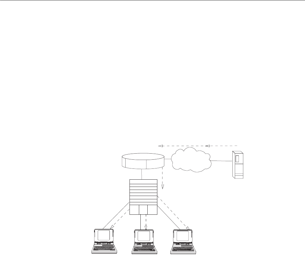
IGMP Snooping 181
IGMP Snooping IGMP Snooping (Internet Group Management Protocol Snooping) is a multicast
control mechanism running on layer 2. It is used for multicast group management
and control.
IGMP Snooping runs on the link layer. When receiving the IGMP messages, the
Layer 2 Switch 8800 uses IGMP Snooping to analyze the information. If the switch
hears an IGMP host report message from an IGMP host, it adds the host to the
corresponding multicast table. If the switch hears IGMP leave a message from an
IGMP host, it will remove the host from the corresponding multicast table. The
switch continuously listens to the IGMP messages to create and maintain a MAC
multicast address table on Layer 2. It can then forward the multicast packets
transmitted from the upstream router according to the MAC multicast address
table.
When IGMP Snooping is disabled, the packets are multicast to all ports. See
Figure 3.
Figure 3 Multicast Packet Transmission Without IGMP Snooping
Packets are not forwarded to all ports when IGMP operates. See Figure 4.
VOD Server
Video stream
Video stream
Video stream Video
stream
Video stream
Multicast
group
member
Nonmulticast
group
member
Nonmulticast
group
member
Layer 2
Ethernet Switch
Multicast router Internet/Intranet
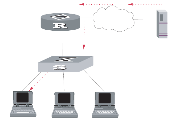
182 CHAPTER 6: MULTICAST PROTOCOL
Figure 4 Multicast Packet Transmission With IGMP Snooping
Implement IGMP Snooping
This section introduces related switch concepts of IGMP Snooping:
■Router Port: The port directly connected to the multicast router.
■Multicast member port: The port connected to the multicast member. The
multicast member refers to a host that joined a multicast group.
■MAC multicast group: The multicast group is identified with MAC multicast
address and maintained by the Switch 8800.
■Router port aging time: Time set on the router port aging timer. If the switch
has not received any IGMP general query messages before the timer times out,
it is no longer considered a router port.
■Multicast group member port aging time: When a port joins an IP multicast
group, the aging timer of the port begins timing. If the switch has not received
any IGMP report messages before the timer times out, it transmits IGMP
specific query message to the port.
■Maximum response time: When the switch transmits IGMP specific query
message to the multicast member port, the Switch 8800 starts a response
timer, which times before the response to the query. If the switch has not
received any IGMP report message before the timer times out, it will remove
the port from the multicast member ports
The Switch 8800 runs IGMP Snooping to listen to the IGMP messages and map
the host and its ports to the corresponding multicast group address. To implement
IGMP Snooping, Switch 8800 processes different IGMP messages shown in the
figure below:
Video stream
Video stream
Video
stream Video stream
Video stream
VOD server
Internet/Intranet
Multicast router
Layer 2
Ethernet switch
Multicast
group
member
Nonmulticast
group
member
Nonmulticast
group
member
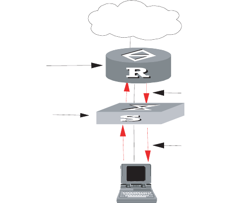
IGMP Snooping 183
Figure 5 Implementing IGMP Snooping
1IGMP general query message: Transmitted by the multicast router to query which
multicast group contains member. When a router port receives an IGMP general
query message, the Switch 8800 will reset the aging timer of the port. When a
port other than a router port receives the IGMP general query message, the Switch
8800 will notify the multicast router that a port is ready to join a multicast group
and starts the aging timer for the port.
2IGMP specific query message: Transmitted from the multicast router to the
multicast members and used for querying if a specific group contains any member.
When received IGMP specific query message, the switch only transmits the specific
query message to the IP multicast group which is queried.
3IGMP report message: Transmitted from the host to the multicast router and used
for applying to a multicast group or responding to the IGMP query message.
When received, the switch checks if the MAC multicast group is ready to join. If
the corresponding MAC multicast group does not exist, the switch notifies the
router that a member is ready to join a multicast group, creates a new MAC
multicast group, adds the port that received the message to the group, starts the
port aging timer, and then adds all the router ports in the native VLAN of the port
into the MAC multicast forwarding table. Meanwhile, it creates an IP multicast
group and adds the port received to it. If the corresponding MAC multicast group
exists but does not contain the port that received the report message, the switch
adds the port into the multicast group and starts the port aging timer. Then, the
switch checks if the corresponding IP multicast group exists. If it does not exist, the
switch creates a new IP multicast group and adds the port that received the report
message to it. If it does exist, the switch adds the port. If the corresponding MAC
multicast group exists and contains the port, the switch will only reset the aging
timer of the port.
4IGMP leave message: Transmitted from the multicast group member to the
multicast router, to notify that a host has left the multicast group. The Switch
8800 transmits the specific query message, concerning the group, to the port that
received the message in an effort to check if the host still has other members of
this group, and then starts a maximum response timer. If the switch has not
received any report message from the multicast group, the port will be removed
from the corresponding MAC multicast group. If the MAC multicast group does
Internet
A router running
IGMP
An Ethernet switch
running IGMP
snooping
IGMP packets
IGMP packets

184 CHAPTER 6: MULTICAST PROTOCOL
not have any member, the switch will notify the multicast router to remove it from
the multicast tree.
Configuring IGMP Snooping is described in the following sections:
■Configuring IGMP Snooping
■IGMP Snooping Configuration Example
■Troubleshooting IGMP Snooping
Configuring IGMP
Snooping
The main IGMP Snooping configuration includes:
■Enabling/Disabling IGMP Snooping
■Configure Router Port Aging Time
■Configuring Maximum Response Time
■Configure Aging Time of Multicast Group Member
■Displaying and Debugging IGMP Snooping
Of the above configuration tasks, enabling IGMP Snooping is required, while
others are optional.
Enabling/Disabling IGMP Snooping
You can use the following commands to enable/disable IGMP Snooping on Layer
2.
Perform the following configuration in system view. To enable IGMP snooping,
you must also issue the igmp-snooping enable command in VLAN view.
IGMP Snooping and GMRP cannot run at the same time. You can check if GMRP is
running by using the display gmrp status command, in all views, before
enabling IGMP Snooping.
By default, IGMP Snooping is disabled.
Configure Router Port Aging Time
Use this to manually configure the router port aging time. If the switch has not
received a general query message from the router prior to it aging, it will remove
the port from all the MAC multicast groups.
Perform the following configuration in system view.
Tab le 20 Enable/Disable IGMP Snooping
Operation Command
Enable/disable IGMP Snooping igmp-snooping { enable | disable }
Restore the default setting undo igmp-snooping
Tab le 21 Configure Router Port Aging Time
Operation Command
Configure router port aging time igmp-snooping router-aging-time seconds
Restore the default aging time undo igmp-snooping router-aging-time
IGMP Snooping 185
By default, the port aging time is 260 seconds.
Configuring Maximum Response Time
This task sets the maximum response time. If the Switch 8800 receives no report
message from a port in the maximum response time, it will remove the port from
the multicast group.
Perform the following configuration in system view.
By default, the maximum response time is 10 seconds.
Configure Aging Time of Multicast Group Member
This task sets the aging time of the multicast group member port. If the switch
receives no multicast group report message during the member port aging time, it
will transmit the specific query message to that port and start a maximum
response timer.
Perform the following configuration in system view.
By default, the aging time of the multicast member is 260 seconds.
Displaying and Debugging IGMP Snooping
Execute the display command in all views to display the operation of the IGMP
Snooping configuration, and to verify the effect of the configuration. Execute the
reset command in user view to reset the IGMP Snooping statistic information.
Execute the debugging command in user view to debug IGMP Snooping
configuration.
Table 22 Configuring the Maximum Response Time
Operation Command
Configure the maximum response time igmp-snooping max-response-time
seconds
Restore the default setting undo IGMP-snooping max-response-time
Table 23 Configure Aging Time of the Multicast Member
Operation Command
Configure aging time of the multicast member igmp-snooping host-aging-time seconds
Restore the default setting undo igmp-snooping host-aging-time
Table 24 Display and Debug IGMP Snooping
Operation Command
Display the information about current IGMP
Snooping configuration display igmp-snooping configuration
Display IGMP Snooping statistics of received
and sent messages display igmp-snooping statistics
Display IP/MAC multicast group information in
the VLAN display igmp-snooping group [ vlan vlanid
]
Enable/disable IGMP Snooping debugging
(abnormal, group, packet, timer).
debug igmp-snooping { all | abnormal |
group | packet | timers }
Reset the IGMP Snooping statistic information reset igmp-snooping statistics
Disable IGMP Snooping debugging (abnormal,
group, packet, timer).
undo debug igmp-snooping { all |
abnormal | group | packet | timers }
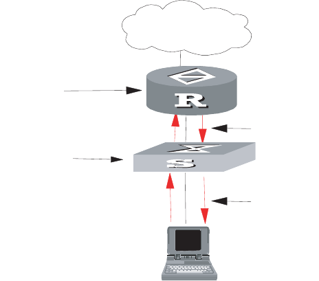
186 CHAPTER 6: MULTICAST PROTOCOL
IGMP Snooping
Configuration Example
To implement IGMP Snooping on the switch, first enable it. The switch is
connected with the router through the router port, and with user PC through the
non-router ports.
Figure 6 IGMP Snooping Configuration Network
1Display the status of GMRP.
<SW8800>display gmrp status
2Display the current status of IGMP Snooping when GMRP is disabled.
<SW8800>display igmp-snooping configuration
3Enable IGMP Snooping if it is disabled.
[SW8800]igmp-snooping enable
Troubleshooting IGMP
Snooping
If the multicast function cannot be implemented on the switch, check for the
following conditions and use the accompanying troubleshooting procedure:
1IGMP Snooping is disabled.
■Input the display current-configuration command to display the status of
IGMP Snooping.
■If the switch disabled IGMP Snooping, you can input igmp-snooping enable
in the system view to enable IGMP Snooping.
2Multicast forwarding table set up by IGMP Snooping is wrong.
■Input the display igmp-snooping group command to see if the multicast
group is the expected one.
■Verify that the source IP address is correct for each multicast stream.
3Multicast forwarding table set up on the bottom layer is wrong.
■Enable IGMP Snooping group in user view and then input the display
igmp-snooping group command to check if MAC multicast forwarding table
in the bottom layer and that created by IGMP Snooping is consistent. You may
also input the display mac vlan command in all views to check if MAC
multicast forwarding table under vlanid in the bottom layer and that created by
IGMP Snooping is consistent.
Internet
A router running
IGMP
An Ethernet switch
running IGMP
snooping
IGMP packets
IGMP packets

Configuring PIM-DM 187
■If they are not consistent, contact the maintenance personnel for help.
Configuring PIM-DM PIM-DM (Protocol Independent Multicast, Dense Mode) belongs to dense mode
multicast routing protocols. PIM-DM is suitable for small networks. Members of
multicast groups are relatively dense in such network environments.
The working procedures of PIM-DM include neighbor discovery, flood and prune,
and graft.
■Neighbor discovery
The PIM-DM router needs to use Hello messages to perform neighbor discovery
when it is started. All network nodes running PIM-DM keep in touch with one
another with Hello messages, which are sent periodically.
■Flood and Prune
PIM-DM assumes that all hosts on the network are ready to receive multicast
data. When a multicast source “S” begins to send data to a multicast group
“G”, after the router receives the multicast packets, the router will perform RPF
check according to the unicast routing table first. If the RPF check is passed, the
router will create an (S, G) entry and then flood the data to all downstream
PIM-DM nodes. If the RPF check is not passed, that is when multicast packets
enter from an error interface, the packets will be discarded. After this process,
an (S, G) entry will be created in the PIM-DM multicast domain.
If the downstream node has no multicast group members, it will send a Prune
message to the upstream nodes to inform the upstream node not to forward
data to the downstream node. Receiving the prune message, the upstream
node will remove the corresponding interface from the outgoing interface list
corresponding to the multicast forwarding entry (S, G). In this way, a SPT
(Shortest Path Tree) rooted at Source S is built. Leaf routers initiate the pruning
process.
This is called the “flood & prune” process. Nodes that are pruned provide
timeout mechanism. Each router re-starts the “flood & prune” process upon
pruning timeout. The consistent “flood & prune” process of PIM-DM is
performed periodically.
During this process, PIM-DM uses the RPF check and the existing unicast
routing table to build a multicast forwarding tree rooted at the data source.
When a packet arrives, the router judges the validity of the path. If the
interface is indicated by the unicast routing to the multicast source, the packet
is regarded to be from the correct path, otherwise, the packet will be discarded
as a redundancy packet without the multicast forwarding. The unicast routing
information as path judgment can come from any unicast routing protocol
independent of any specified unicast routing protocol such as the routing
information learned by RIP and OSPF.
■Assert mechanism
As shown in the following figure, both routers A and B on the LAN have their
own receiving paths to multicast source S. In this case, when they receive a
multicast packet sent from multicast source S, they will both forward the
packet to the LAN. Multicast Router C at the downstream node will receive two
copies of the same multicast packet.
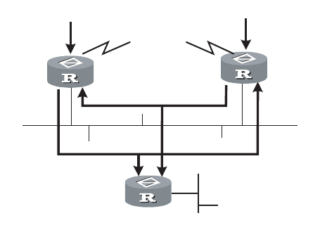
188 CHAPTER 6: MULTICAST PROTOCOL
Figure 7 Assert Mechanism Diagram
When they detect such a case, routers need to select a unique sender by using
the assert mechanism. Routers send Assert packets to select the best path. If
two or more have the same priority and metric, the path with a higher IP
address will be the upstream neighbor of the (S, G) entry. This is responsible for
forwarding the (S, G) multicast packet.
■Graft
When the pruned downstream node needs to be restored to the forwarding
state, the node will send a graft packet to inform the upstream node.
Configuring PIM-DM is described in the following sections:
■Configuring PIM-DM
■PIM-DM Configuration Example
Configuring PIM-DM Basic PIM-DM configuration includes:
■Enabling Multicast
■Enabling PIM-DM
■Entering PIM View
Advanced PIM-DM configuration includes:
■Configuring the Interface Hello Message Interval
■Configuring the Filtering of Multicast Source/Group
■Configuring the Filtering of PIM Neighbors
■Configuring the Maximum Number of PIM Neighbor on an Interface
■Clearing PIM Neighbors
■Displaying and Debugging PIM-DM
When the router is run in the PIM-DM domain, it is best to enable PIM-DM on all
interfaces of the non-border router.
Enabling Multicast
See “Configuring Common Multicast ” on page 172.
Multicast packets forwarded
by the upstream node
R
outer A Router B
Receiver
Router C

Configuring PIM-DM 189
Enabling PIM-DM
PIM-DM needs to be enabled in the configuration of all interfaces.
After PIM-DM is enabled on an interface, it will send PIM Hello messages
periodically, and process protocol packets sent by PIM neighbors.
Perform the following configuration in VLAN interface view.
3Com recommends that you configure PIM-DM on all interfaces. This
configuration is effective only after the multicast routing is enabled in system view.
Once you enable PIM-DM on an interface, PIM-SM cannot be enabled on the
same interface and vice versa.
Entering PIM View
Global parameters of PIM should be configured in PIM view.
Perform the following configuration in system view.
Use the undo pim command to clear the configuration in PIM view, and to return
to system view.
Configuring the Interface Hello Message Interval
After PIM is enabled on an interface, it will send Hello messages periodically. The
interval at which Hello messages are sent can be modified according to the
bandwidth and type of the network connected to the interface.
Perform the following configuration in VLAN interface view.
The default interval is 30 seconds. You can configure the value according to
different network environments. Generally, this parameter does not need to be
modified.
This configuration can be performed only after PIM (PIM-DM or PIM-SM) is
enabled in VLAN interface view.
Table 25 Enable PIM-DM
Operation Command
Enable PIM-DM on an interface pim dm
Disable PIM-DM on an interface undo pim dm
Table 26 Entering PIM View
Operation Command
Enter PIM view pim
Return to system view undo pim
Table 27 Configure Hello Message Interval on an Interface
Operation Command
Configure the hello message interval on an
interface
pim timer hello seconds
Restore the interval to the default value undo pim timer hello

190 CHAPTER 6: MULTICAST PROTOCOL
Configuring the Filtering of Multicast Source/Group
You can set to filter the source (and group) address of multicast data packets via
this command. When this feature is configured, the router filters not only
multicast data, but the multicast data encapsulated in the registration packets.
Perform the following configuration in the PIM view.
If resource address filtering is configured, as well as basic ACLs, then the router
filters the resource addresses of all multicast data packets received. Those not
matched will be discarded.
If resource address filtering is configured, as well as advanced ACLs, then the
router filters the resource and group addresses of all multicast data packets
received. Those not matched will be discarded.
Configuring the Filtering of PIM Neighbors
You can set to filter the PIM neighbors on the current interface via the following
configuration.
Perform the following configuration in the PIM view.
By default, no filtering rules are set.
Only the routers that match the filtering rule in the ACL can serve as a PIM
neighbor of the current interface.
Configuring the Maximum Number of PIM Neighbor on an Interface
You can limit the PIM neighbors on an interface. No neighbor can be added any
more when the limit is reached.
Perform the following configuration in the PIM view.
By default, the PIM neighbors on the interface are limited to 128.
Tab le 28 Configuring the Filtering of Multicast Source/Group
Operation Command
Configure the filtering of multicast
source/group
source-policy acl-number
Remove the configuration of filtering undo source-policy
Tab le 29 Configuring the Filtering of PIM Neighbors
Operation Command
Configure filtering of PIM neighbor pim neighbor-policy acl-number
Remove the configuration of filtering undo pim neighbor-policy
Tab le 30 Configure the Maximum Number of PIM Neighbor on an Interface
Operation Command
Configure the maximum number of PIM
neighbor on an interface
pim neighbor-limit limit
Restore the limit of PIN neighbor to the
default value
pim neighbor-limit

Configuring PIM-DM 191
If the existing PIM neighbors exceed the configured value during configuration,
they are not deleted.
Clearing PIM Neighbors
Perform the following configuration in user view.
Displaying and Debugging PIM-DM
Execute the display command in all views to display the operation of the PIM-DM
configuration, and to verify the effect of the configuration.
Execute the debugging command in user view for the debugging of PIM-DM.
PIM-DM Configuration
Example
LS_A has a port carrying Vlan 10 to connect Multicast Source, a port carrying
Vlan11 to connect LS_B and a port carrying Vlan12 to connect LS_C. Configure to
implement multicast between Multicast Source and Receiver 1 and Receiver 2.
Table 31 Resetting PIM Neighbors
Operation Command
Clear PIM neighbors reset pim neighbor { all | { neighbor-address |
interface interface-type interface-number } * }
Table 32 Displaying and Debugging PIM-DM
Operation Command
Display the PIM multicast routing table display pim routing-table [ { { *g [
group-address [ mask { mask-length | mask } ]
] | **rp [ rp-address [ mask { mask-length |
mask } ] ] } | { group-address [ mask {
mask-length | mask } ] | source-address [ mask
{ mask-length | mask } ] } * } |
incoming-interface { interface-type
interface-num | interface-name | null } | {
dense-mode | sparse-mode } ] *
Display the PIM interface information display pim interface [ interface-type
interface-number ]
Display the information about PIM
neighboring routers
display pim neighbor [ interface
interface-type interface-number ]
Enable the PIM debugging debugging pim common { all | event |
packet | timer }
Disable the PIM debugging undo debugging pim common { all | event
| packet | timer }
Enable the PIM-DM debugging debugging pim dm { alert | all | mbr | mrt |
timer | warning | { recv | send } { all | assert
| graft | graft-ack | join | prune } }
Disable the PIM-DM debugging undo debugging pim dm { alert | all | mbr |
mrt | timer | warning | { recv | send } { all |
assert | graft | graft-ack | join | prune } }
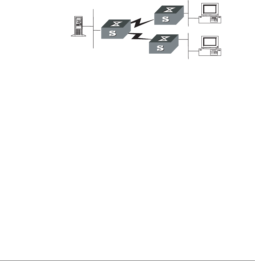
192 CHAPTER 6: MULTICAST PROTOCOL
Figure 8 PIM-DM Configuration Networking
Configuration procedure
This section only provides the configuration for Switch A because the
configuration procedures for Switch B and Switch C are similar.
1Enable the multicast routing protocol.
[SW8800]multicast routing-enable
2Enable PIM-DM.
[SW8800]vlan 10
[SW8800-vlan10] port GigabitEthernet1/1/2 to GigabitEthernet1/1/3
[SW8800-vlan10] quit
[SW8800]vlan 11
[SW8800-vlan11] port GigabitEthernet1/1/4 to GigabitEthernet1/1/5
[SW8800-vlan11] quit
[SW8800]vlan 12
[SW8800-vlan12] port GigabitEthernet1/1/6 to GigabitEthernet1/1/7
[SW8800-vlan12] quit
[SW8800]interface vlan-interface 10
[SW8800-vlan-interface10] ip address 1.1.1.1 255.255.0.0
[SW8800-vlan-interface10] igmp enable
[SW8800-vlan-interface10] pim dm
[SW8800-vlan-interface10] quit
[SW8800]interface vlan-interface 11
[SW8800-vlan-interface11] ip address 2.2.2.2 255.255.0.0
[SW8800-vlan-interface11] igmp enable
[SW8800-vlan-interface11] pim dm
[SW8800-vlan-interface11] quit
[SW8800]interface vlan-interface 12
[SW8800-vlan-interface12] ip address 3.3.3.3 255.255.0.0
[SW8800-vlan-interface12] igmp enable
[SW8800-vlan-interface12] pim dm
Configuring PIM-SM PIM-SM (Protocol Independent Multicast, Sparse Mode) belongs to sparse mode
multicast routing protocols. PIM-SM is mainly applicable to large-scale networks
with broad scope and few group members.
Different from the flood & prune principle of the dense mode, PIM-SM assumes
that all hosts do not need to receive multicast packets, unless clear request is put
forward.
PIM-SM uses the RP (Rendezvous Point) and the BSR (Bootstrap Router) to
advertise multicast information to all PIM-SM routers and uses the join/prune
Multicast
source
VLAN10
Switch A VLAN12
VLAN11
Switch B
Switch C
Receiver 1
Receiver 2
Configuring PIM-SM 193
information of the router to build the RP-rooted shared tree (RPT). This helps to
reduce the bandwidth occupied by data packets and control packets, and reduces
the process overhead of the router. Multicast data flows along the shared tree to
the network segments. When data traffic is sufficient, the multicast data flow
switches over to the SPT (Shortest Path Tree) rooted on the source. This reduces
network delay. To perform the RPF check, PIM-SM does not depend on the
specified unicast routing protocol but uses the present unicast routing table.
If your switch is using PIM-SM, you must configure candidate RPs and BSRs. The
BSR is responsible for collecting the information from the candidate RP and
advertising the information.
Configuring PIM-SM is described in the following sections:
■PIM-SM Operating Principles
■Preparing to Configure PIM-SM
■Configuring PIM-SM
PIM-SM Operating
Principles
The PIM-SM working process is as follows: neighbor discovery, building the
RP-rooted shared tree (RPT), multicast source registration and SPT switchover etc.
The neighbor discovery mechanism is the same as that of PIM-DM.
Build the RP shared tree (RPT)
When hosts join a multicast group G, the leaf routers send IGMP messages to
learn the receivers of the multicast group G. The leaf routers calculate the
corresponding rendezvous point (RP) for multicast group G, and then send join
messages to the node of a higher level toward the rendezvous point (RP). Each
router along the path, between the leaf routers and the RP, will generate (*, G)
entries in the forwarding table, indicating that all packets sent to multicast group
G are applicable. When the RP receives packets sent to multicast group G, the
packets will be sent to leaf routers along the path built and then reach the hosts.
In this way, an RP-rooted tree (RPT) is built as shown in the following figure.
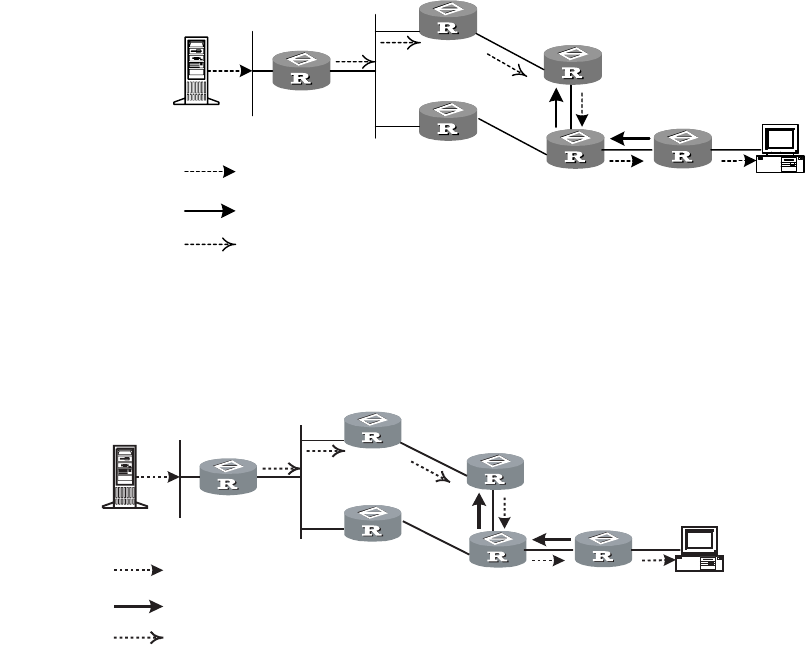
194 CHAPTER 6: MULTICAST PROTOCOL
Figure 9 RPT Schematic Diagram
Multicast Source Registration
When multicast source S sends a multicast packet to group G, the PIM-SM
multicast router is responsible for encapsulating the packet into a registration
packet upon receipt. It then sends the packet to the corresponding RP in unicast. If
there are multiple PIM-SM multicast routers on a network segment, the
Designated Router (DR) will be responsible for sending the multicast packet.
Preparing to Configure
PIM-SM
Tasks for preparing to Configure PIM-SM are described in the following sections:
■Configure Candidate RPs
■Configure BSRs
■Configure Static RP
Configure Candidate RPs
In a PIM-SM network, multiple RPs (candidate-RPs) can be configured. Each
Candidate-RP (C-RP) is responsible for forwarding multicast packets with the
destination addresses in a certain range. Configuring multiple C-RPs is to
implement load balancing of the RP. These C-RPs are equal. All multicast routers
Multicast Source S
RPT
join
Multicast source registration
RP
Receiver
RPT
join
Multicast source
registration
Multicast source S
RP
Receiver

Configuring PIM-SM 195
calculate the RPs corresponding to multicast groups according to the same
algorithm, after receiving the C-RP messages that the BSR advertises.
One RP can serve multiple multicast groups or all multicast groups. Each multicast
group can only be uniquely correspondent to one RP at a time rather than multiple
RPs.
Configure BSRs
The BSR is the management core in a PIM-SM network. Candidate-RPs send
announcement to the BSR, which is responsible for collecting and advertising the
information about all candidate-RPs.
It should be noted that there can be only one BSR in a network but you can
configure multiple candidate-BSRs. In this case, once a BSR fails, you can switch
over to another BSR. A BSR is elected among the C-BSRs automatically. The C-BSR
with the highest priority is elected as the BSR. If the priority is the same, the C-BSR
with the largest IP address is elected as the BSR.
Configure Static RP
The router that serves as the RP is the core router of multicast routes. If the
dynamic RP elected by BSR mechanism is invalid for some reason, the static RP can
be configured to specify RP. As the backup of dynamic RP, static RP improves
network robustness and enhances the operation and management capability of
multicast network.
Configuring PIM-SM Basic PIM-SM configuration includes:
■Enabling Multicast
■Enabling IGMP on an Interface
■Enabling PIM-SM
■Setting the PIM-SM Domain Border
■Entering PIM View
■Configuring Candidate-BSRs
■Configuring Candidate-RPs
■Configuring Static RP
Advanced PIM-SM configuration includes:
■Configuring the Interface Hello Message Interval
■Configuring the Filtering of Multicast Source/Group
■Configuring the Filtering of PIM Neighbor
■Configuring the Maximum Number of PIM Neighbor on an Interface
■Configuring RP to Filter the Register Messages Sent by DR
■Limiting the Range of Legal BSR
■Limiting the Range of Legal C-RP
■Clearing Multicast Route Entries from PIM Routing Table
■Clearing PIM Neighbors

196 CHAPTER 6: MULTICAST PROTOCOL
■Displaying and Debugging PIM-SM
At least one router in an entire PIM-SM domain should be configured with
Candidate-RPs and Candidate-BSRs.
Enabling Multicast
Refer to “Configuring Common Multicast ” on page 172.
Enabling IGMP on an Interface
Refer to “Configuring IGMP” on page 174.
Enabling PIM-SM
This configuration can be effective only after multicast is enabled.
Perform the following configuration in VLAN interface view.
Repeat this configuration to enable PIM-SM on other interfaces. Only one
multicast routing protocol can be enabled on an interface at a time.
Once enabled, PIM-DM cannot be enabled on the same interface.
Setting the PIM-SM Domain Border
After the PIM-SM domain border is configured, bootstrap messages cannot cross
the border in any direction. In this way, the PIM-SM domain can be split.
Perform the following configuration in VLAN interface view.
By default, no domain border is set. After this configuration is performed, a
bootstrap message cannot cross the border, but other PIM packets can. This
configuration can effectively divide a network into domains using different BSRs.
This command cannot create a multicast packet forwarding border but only a PIM
bootstrap message border.
Entering PIM View
Global parameters of PIM should be configured in PIM view.
Tab le 33 Enabling PIM-SM
Operation Command
Enable PIM-SM on an interface pim sm
Disable PIM-SM on an interface undo pim sm
Tab le 34 Setting the PIM-SM Domain Border
Operation Command
Set the PIM-SM domain border pim bsr-boundary
Remove the PIM-SM domain border
configured
undo pim bsr-boundary

Configuring PIM-SM 197
Perform the following configuration in system view.
Using undo pim command, you can clear the configuration in PIM view and back
to system view.
Configuring Candidate-BSRs
In a PIM domain, one or more candidate BSRs should be configured. A BSR
(Bootstrap Router) is elected among candidate BSRs. The BSR takes charge of
collecting and advertising RP information.
The automatic election among candidate BSRs is described as follows. One
interface which has started PIM-SM, must be specified when configuring the
router as the candidate BSR. At first, each candidate BSR considers itself as the BSR
of the PIM-SM domain, and sends a Bootstrap message by taking the IP address of
the interface as the BSR address. When receiving Bootstrap messages from other
routers, the candidate BSR will compare the BSR address of the newly received
Bootstrap message with that of itself. Comparison standards include priority and
IP address. The bigger IP address is considered better when the priority is the same.
If the new BSR address is better, the candidate BSR will replace its BSR address.
Otherwise, the candidate BSR will keep its BSR address and continue to regard
itself as the BSR.
Perform the following configuration in PIM view.
Candidate-BSRs should be configured on the routers in the network backbone. By
default, no BSR is set. The default priority is 0.
Only one router can be configured with one candidate-BSR. When a
candidate-BSR is configured on another interface, it will replace the previous
configuration.
Configuring Candidate-RPs
In PIM-SM, the shared tree built by the multicast routing data is rooted at the RP.
There is mapping from a multicast group to an RP. A multicast group can be
mapped to an RP. Different groups can be mapped to one RP.
Table 35 Entering PIM View
Operation Command
Enter PIM view pim
Back to system view undo pim
Table 36 Configuring Candidate-BSRs
Operation Command
Configure a candidate-BSR c-bsr interface-type interface-number
hash-mask-len [ priority ]
Remove the candidate-BSR configured undo c-bsr

198 CHAPTER 6: MULTICAST PROTOCOL
Perform the following configuration in PIM view.
If the range of the served multicast group is not specified, the RP will serve all
multicast groups. Otherwise, the range of the served multicast group is the
multicast group in the specified range. It is suggested to configure Candidate RP
on the backbone router.
Configuring Static RP
Static RP serves as the backup of dynamic RP to make the network more robust.
Perform the following configuration in PIM view.
Basic ACLs can control the range of the multicast group served by static RP.
If static RP is in use, all routers in the PIM domain must adopt the same
configuration. If the configured static RP address is the interface address of the
local router whose state is UP, the router will function as the static RP. It is
unnecessary to enable PIM on the interface that functions as static RP.
When the RP elected from BSR mechanism is valid, static RP does not work.
Configuring the Interface Hello Message Interval
Generally, PIM-SM advertises Hello messages periodically on the interface enabled
with it to detect PIM neighbors and discover which router is the Designated Router
(DR).
Perform the following configuration in VLAN interface view.
By default, the hello message interval is 30 seconds. Users can configure the value
according to different network environments.
This configuration can be performed only after the PIM (PIM-DM or PIM-SM) is
enabled in VLAN interface view.
Tab le 37 Configuring Candidate-RPs
Operation Command
Configure a candidate-RP c-rp interface-type interface-number [
group-policy acl-number ]
Remove the candidate-RP configured undo c-rp interface-type interface-number
Tab le 38 Configuring Static RP
Operation Command
Configure static RP static-rp rp-address [ acl-number ]
Configure static RP undo static-rp
Tab le 39 Configuring the Interface Hello Message Interval
Operation Command
Configure the interface hello message interval pim timer hello seconds
Restore the interval to the default value undo pim timer hello
Configuring PIM-SM 199
Configuring the Filtering of Multicast Source/Group
See “Configuring PIM-DM” on page 187.
Configuring the Filtering of PIM Neighbor
See “Configuring PIM-DM” on page 187.
Configuring the Maximum Number of PIM Neighbor on an Interface
See “Configuring PIM-DM” on page 187.
Configuring RP to Filter the Register Messages Sent by DR
In the PIM-SM network, the register message filtering mechanism can control
which sources to send messages to, which groups on the RP, i.e., RP can filter the
register messages sent by DR to accept specified messages only.
Perform the following configuration in PIM view.
If an entry of a source group is denied by the ACL, or the ACL does not define
operation to it, or there is no ACL defined, the RP will send RegisterStop messages
to the DR to prevent the register process of the multicast data stream.
Only the register messages matching the ACL permit clause can be accepted by
the RP. Specifying an undefined ACL will make the RP deny all register messages.
Limiting the Range of Legal BSR
In a PIM SM network that uses a bootstrap router (BSR), every router can set itself
as a candidate BSR (C-BSR) and take the authority to advertise RP information in
the network when it wins in the contention. To prevent malicious BSR spoofing in
the network, the following two measures need to be taken:
■Prevent the router from being spoofed by hosts using a stolen identity from
legal BSR messages to modify RP mapping. BSR messages are of multicast type
and their TTL is 1, so these types of attacks often hit edge routers. Fortunately,
BSRs are inside the network, while assaulting hosts are outside, therefore
neighbor and RPF checks can be used to stop these types of attacks.
■If a router in the network is manipulated by an attacker, or an illegal router is
accessed into the network, the attacker may set itself as C-BSR and try to win
the contention and gain authority to advertise RP information among the
network. Since the router configured as C-BSR shall propagate BSR messages,
which are multicast messages sent hop by hop with TTL as 1, among the
network, then the network cannot be affected as long as the peer routers do
not receive these BSR messages. One way is to configure bsr-policy on each
router to limit legal BSR range, for example, only 1.1.1.1/32 and 1.1.1.2/32 can
be BSR, thus the routers cannot receive or forward BSR messages other than
these two. Even legal BSRs cannot contest with them.
Table 40 Configuring RP to Filter the Register Messages Sent by DR
Operation Command
Configure RP to filter the register messages
sent by DR
register-policy acl-number
Cancel the configured filter of messages undo register-policy

200 CHAPTER 6: MULTICAST PROTOCOL
Perform the following configuration in PIM view.
For detailed information of the bsr-policy command, see the Switch 8800
Command Reference Guide.
Limiting the Range of Legal C-RP
In the PIM SM network, using BSR mechanism, every router can set itself as the
C-RP (candidate rendezvous point) servicing particular groups. If elected, a C-RP
becomes the RP servicing the current group.
In the BSR mechanism, a C-RP router unicasts C-RP messages to the BSR, which
then propagates the C-RP messages among the network by BSR message. To
prevent C-RP spoofing, you need to configure crp-policy on the BSR to limit legal
C-RP range and their service group range. Since each C-BSR has the chance to
become BSR, you must configure the same filtering policy on each C-BSR router.
Perform the following configuration in PIM view.
For detailed information of the crp-policy command, see the Switch 8800
Command Reference Guide.
Clearing Multicast Route Entries from PIM Routing Table
Perform the following configuration in user view.
If in this command, the group-address is 224.0.0.0/24 and source-address is the
RP address (where group address can have a mask, but the resulting IP address
must be 224.0.0.0, and source address has no mask), then it means only the (*, *,
RP) item will be cleared.
If in this command, the group-address is any group address, and source-address is
0 (where group address can have a mask, and source address has no mask), then
only the (*, G) item will be cleared.
Tab le 41 Limiting the Range of Legal BSR
Operation Command
Limit the legal BSR range bsr-policy acl-number
Restore to the default setting undo bsr-policy
Tab le 42 Limiting the Range of Legal C-RP
Operation Command
Limit the legal C-RP range crp-policy acl-number
Restore to the default setting undo crp-policy
Tab le 43 Clearing Multicast Route Entries from PIM Routing Table
Operation Command
Clear multicast route entries from PIM routing
table
reset pim routing-table { all | {
group-address [ mask group-mask |
mask-length group-mask-length ] |
source-address [ mask source-mask |
mask-length source-mask-length ] | {
incoming-interface { interface-type
interface-number | null } } } * }

Configuring PIM-SM 201
This command clears multicast route entries from PIM routing table, as well as the
corresponding route entries and forward entries in the multicast core routing table
and MFC.
Clearing PIM Neighbors
Perform the following configuration in user view.
Displaying and Debugging PIM-SM
Execute the display command in all views to display the PIM-SM configuration,
and to verify the configuration.
Execute the debugging command in user view to debug PIM-SM.
Example: Configuring
PIM-SIM
Host A is the receiver of the multicast group at 225.0.0.1. Host B begins
transmitting data destined to 225.0.0.1. Switch A receives the multicast data from
Host B by Switch B.
Figure 10 PIM-SM Configuration Networking
Table 44 Clearing PIM Neighbors
Operation Command
Clear PIM neighbors reset pim neighbor { all | { neighbor-address
| interface interface-type interface-number }
* }
Table 45 Display and Debug PIM-SM
Operation Command
Display the BSR information display pim bsr-info
Display the RP information display pim rp-info [ group-address ]
Enable the PIM-SM debugging debugging pim sm { all | mbr |
register-proxy | mrt | timer | warning | {
recv | send } { assert | graft | graft-ack | join
| prune } }
Disable the PIM-SM debugging undo debugging pim sm { all | mbr |
register-proxy | mrt | timer | warning | {
recv | send } { assert | graft | graft-ack | join
| prune } }
Host A Host B
VLAN12
VLAN10
VLAN10 VLAN11
VLAN11
VLAN12 VLAN10
VLAN12
VLAN11
LSD
202 CHAPTER 6: MULTICAST PROTOCOL
Configure Switch A
1Enable PIM-SM.
[SW8800]multicast routing-enable
[SW8800]vlan 10
[SW8800-vlan10] port GigabitEthernet1/1/2 to GigabitEthernet1/1/3
[SW8800-vlan10] quit
[SW8800]interface vlan-interface 10
[SW8800-vlan-interface10] pim sm
[SW8800-vlan-interface10] quit
[SW8800]vlan 11
[SW8800-vlan11] port GigabitEthernet1/1/4 to GigabitEthernet1/1/5
[SW8800-vlan11] quit
[SW8800]pim
[SW8800-pim] interface vlan-interface 11
[SW8800-vlan-interface11] pim sm
[SW8800-vlan-interface11] quit
[SW8800]vlan 12
[SW8800-vlan12] port GigabitEthernet1/1/6 to GigabitEthernet1/1/7
[SW8800-vlan12] quit
[SW8800]pim
[SW8800-pim] interface vlan-interface 12
[SW8800-vlan-interface12] pim sm
[SW8800-vlan-interface12] quit
Configure Switch B
1Enable PIM-SM.
[SW8800]multicast routing-enable
[SW8800]vlan 10
[SW8800-vlan10] port GigabitEthernet1/1/2 to GigabitEthernet1/1/3
[SW8800-vlan10] quit
[SW8800]pim
[SW8800-pim] interface vlan-interface 10
[SW8800-vlan-interface10] pim sm
[SW8800-vlan-interface10] quit
[SW8800]vlan 11
[SW8800-vlan11] port GigabitEthernet1/1/4 to GigabitEthernet1/1/5
[SW8800-vlan11] quit
[SW8800]pim
[SW8800-pim] interface vlan-interface 11
[SW8800-vlan-interface11] pim sm
[SW8800-vlan-interface11] quit
[SW8800]vlan 12
[SW8800-vlan12] port GigabitEthernet1/1/6 to GigabitEthernet1/1/7
[SW8800-vlan12] quit
[SW8800]pim
[SW8800-pim] interface vlan-interface 12
[SW8800-vlan-interface12] pim sm
[SW8800-vlan-interface12] quit
2Configure the C-BSR.
[SW8800]pim
[SW8800-pim] c-bsr vlan-interface 10 30 2
3Configure the C-RP.
[SW8800]acl number 2005
[SW8800-acl-basic-2005] rule permit source 225.0.0.0 0.255.255.255

GMRP 203
[SW8800]pim
[SW8800-pim] c-rp vlan-interface 10 group-policy 2005
4Configure PIM domain border.
[SW8800]interface vlan-interface 12
[SW8800-vlan-interface12] pim bsr-boundary
After VLAN-interface 12 is configured as BSR, the LS_D will be excluded from the
local PIM domain and cannot receive the BSR information transmitted from LS_B
anymore.
Configure Switch C:
1Enable PIM-SM.
[SW8800]multicast routing-enable
[SW8800]vlan 10
[SW8800-vlan10] port GigabitEthernet1/1/2 to GigabitEthernet1/1/3
[SW8800-vlan10] quit
[SW8800]pim
[SW8800-pim] interface vlan-interface 10
[SW8800-vlan-interface10] pim sm
[SW8800-vlan-interface10] quit
[SW8800]vlan 11
[SW8800-vlan11] port GigabitEthernet1/1/4 to GigabitEthernet1/1/5
[SW8800-vlan11] quit
[SW8800]pim
[SW8800-pim] interface vlan-interface 11
[SW8800-vlan-interface11] pim sm
[SW8800-vlan-interface11] quit
[SW8800]vlan 12
[SW8800-vlan12] port GigabitEthernet1/1/6 to GigabitEthernet1/1/7
[SW8800-vlan12] quit
[SW8800]pim
[SW8800-pim] interface vlan-interface 12
[SW8800-vlan-interface12] pim sm
[SW8800-vlan-interface12] quit
GMRP GMRP (GARP Multicast Registration Protocol), based on GARP, is used for
maintaining dynamic multicast registration information. All the switches
supporting GMRP can receive multicast registration information from other
switches, and dynamically update local multicast registration information. Local
multicast registration information can be transmitted to other switches. This
information switching mechanism keeps consistency of multicast information
maintained by every GMRP-supporting device in the same switching network.
A host transmits GMRP Join message. After receiving the message, the switch
adds the port to the multicast group, and broadcasts the message throughout the
VLAN; thereby the multicast source in the VLAN knows the multicast member.
When the multicast source sends packets to its group, the switch only forwards
the packets to the ports connected to members, thereby implementing the Layer 2
multicast in VLAN.
204 CHAPTER 6: MULTICAST PROTOCOL
The multicast information transmitted by GMRP includes, local static multicast
registration information configured manually, and the multicast registration
information dynamically registered by other switches.
Configuring GMRP The main tasks in a GMRP configuration are described in the following sections:
■Enable/Disable GMRP Globally
■Enabling/Disabling GMRP on the Port
■Displaying and Debugging GMRP
In the configuration process, GMRP must be enabled globally before it is enabled
on the port.
Enable/Disable GMRP Globally
Perform the following configuration in system view.
By default, GMRP is disabled.
Enabling/Disabling GMRP on the Port
Perform the following configuration in Ethernet port view.
GMRP should be enabled globally before being enabled on a port.
By default, GMRP is disabled on the port.
Displaying and Debugging GMRP
After the previous configuration, execute the display command to display the
GMRP configuration, and to verify the effect of the configuration.
Execute the debugging command in user view to debug GMRP configuration.
Tab le 46 Enabling/Disabling GMRP Globally
Operation Command
Enable GMRP globally. gmrp
Disable GMRP globally. undo gmrp
Tab le 47 Enabling/Disabling GMRP on the Port
Operation Command
Enable GMRP on the port gmrp
Disable GMRP on the port undo gmrp
Tab le 48 Display and Debug GMRP
Operation Command
Display GMRP statistics. display gmrp statistics [ interface
interface_list ]
Display GMRP global status. display gmrp status
Enable GMRP debugging debugging gmrp
Disable GMRP debugging undo debugging gmrp event
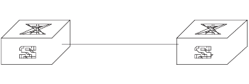
GMRP 205
Example: Configuring
GMRP
Implement dynamic registration and an update of multicast information between
switches.
Figure 11 GMRP Networking
Configure LS_A:
1Enable GMRP globally.
[SW8800]gmrp
2Enable GMRP on the port.
[SW8800]interface GigabitEthernet1/1/1
[SW8800-Ethernet1/1/1] gmrp
Configure LS_B:
1Enable GMRP globally.
[SW8800]gmrp
2Enable GMRP on the port.
[SW8800]interface GigabitEthernet1/1/1
[SW8800-Ethernet1/1/1] gmrp
Switch A Switch B
E0/1 E0/1
206 CHAPTER 6: MULTICAST PROTOCOL

7QOS/ACL OPERATION
This chapter covers the following topics:
■ACL Overview
■Configuring ACLs
■Displaying and Debugging ACL Configurations
■ACL Configuration Example
■QoS Configuration
■Configuration Examples
■Configuring Logon User ACL Control
ACL Overview The Access Control List (ACL) classifies the data packets with a series of matching
rules, including source address, destination address and port number. The switch
verifies the data packets with the rules in the ACL and decides to forward,
prioritize, or discard them.
A series of matching rules are required for the network devices to identify the
packets. After identifying the packets, the switch can permit or deny them to pass
through according to the defined policy. The ACL is used to implement these
functions.
The data packet matching rules, that are defined by ACL, can also be used in other
cases requiring traffic classification, such as defining traffic classification for QoS.
An access control rule includes several statements. Different statements specify
different ranges of packets. When matching a data packet with the access control
rule, the issue of match-order arises.
ACLs Activated Directly
on Hardware
ACLs can be delivered to hardware for traffic filtering and classification. In this
case, the matching order of many sub-rules in an ACL is determined by hardware,
not by a customized order.
ACLs are sent directly to hardware when referencing ACLs to provide for QoS
functions and when filtering and forwarding packets with ACLs.
ACLs Referenced by
Upper-level Modules
An ACL can be used to filter or classify the data transmitted by the software of the
switch. The user can determine the match order of ACL’s sub-rules. There are two
match-orders: configuration, which follows the user-defined configuration order
when matching the rule, and automatic, which follows the depth-first principle.
The depth-first principle puts the statement specifying the smallest range of
addresses on the top of the list. For example, 129.102.1.1 0.0.0.0 specifies a host,

208 CHAPTER 7: QOS/ACL OPERATION
while 129.102.1.1 0.0.255.255 specifies the network segment 129.102.0.1
through 129.102.255.255. The host is listed first in the access control list. The
specific standard is:
■For basic ACL statements, source address wildcards are compared directly. If
the wildcards are the same, the configuration sequence is used.
■For the ACL based on the interface filter, the rule that is configured is listed at
the end, while others follow the configuration sequence.
■For the advanced ACL, source address wildcards are compared first. If they are
the same, then destination address wildcards are compared. For the same
destination address wildcards, ranges of port numbers are compared and the
smaller range is listed first. If the port numbers are in the same range, the
configuration sequence is used.
After you specify the match-order of an access control rule, you cannot modify it
later unless you delete all the contents and specify the match-order again.
This type of filtering includes ACLs cited by route policy function, ACLs used for
controlling user logons, and so on.
ACLs Supported The switch supports these types of ACLs:
■Number-based basic ACLs
■Name-based basic ACLs
■Number-based advanced ACLs
■Name-based advanced ACLs
■Number-based L2 ACLs
■Name-based L2 ACLs
The ranges for the ACLs available on the switch are listed in the following table.
Configuring ACLs 3Com recommends that you perform ACL configuration tasks in the order of the
following sections:
■Configuring Time Range
■Defining and Applying a Flow Template
Tab le 1 Requirements for ACLs
Item Number range
Number-based basic ACL 2000~2999
Number-based advanced ACL 3000~3999
Number-based L2 ACL 4000~4999
Name-based basic ACL -
Name-based advanced ACL -
Name-based L2 ACL --
Maximum sub-rules for an ACL 0~127
Maximum sub-rules for the switch (sum
of the sub-rules of all ACLs)

Configuring ACLs 209
■Defining ACLs
■Activating ACLs
3Com recommends you perform the configuration tasks in the order in which they
appear in this section.
Configuring Time Range The process of configuring a time-range includes configuring the hour-minute
range, date range, and period range. The hour-minute range is expressed in the
units of minutes and hour (hh:mm). The date range is expressed in the units of
date, month, and year (MM-DD-YYYY). The periodic time range is expressed by
the day of the week (Sunday through Saturday).
Perform the following configurations in system view.
When the start-time and end-time are not configured, they are set to define one
day. The end time must be later than the start time.
When the end-time end-date is not configured, it will be all the time from now to
the latest date that can be displayed by the system. The end time must be later
than the start time.
Defining and Applying a
Flow Template
Defining a Flow Template
A flow template defines useful information used in flow classification. For
example, a template defines a quadruple: source and destination IP, source and
destination TCP ports, and then only those traffic rules including all these elements
can be sent to target hardware and referenced for such QoS functions as packet
filtering, traffic policing, and priority re-labeling. Otherwise, the rules cannot be
activated on the hardware and referenced.
Perform the following configurations in system view.
Table 2 Configuring Time Range
Operation Command
Create time range time-range time-name { start-time to end-time
days-of-the-week [ from start-time start-date ] [ to
end-time end-date ] | from start-time start-date [ to
end-time end-date ] | to end-time end-date }
Delete time range undo time-range time-name [ start-time to
end-time days-of-the-week [ from start-time
start-date ] [ to end-time end-date ] | from
start-time start-date [ to end-time end-date ] | to
end-time end-date ]
Table 3 Defining a Flow Template
Operation Command
Define flow template flow-template user-defined { template-info | vpn }
Delete flow template undo flow-template user-defined

210 CHAPTER 7: QOS/ACL OPERATION
Note that the sum of all elements should be less than 16 bytes in length. The
following table lists the length of the elements involved.
The numbers listed in the table are not the actual length of these elements in IP
packets, but their length in a flow template. DSCP field is one byte in a flow
template, but six bytes in IP packets. You can judge the total length of template
elements using these numbers.
The dscp, ip-precedence and tos fields jointly occupy one byte. One byte is
occupied no matter you define one, two or three of these fields.
The fragment field is 0 in length in flow template, so it can be ignored in
calculating the total length of template elements.
You can use the default template, which defines a quintuple: source and
destination IP addresses, source and destination TCP/UDP ports, IP protocol. You
may also define a flow template based on your needs.
You cannot modify or delete the default flow template.
Applying a Flow Template
Perform the following configurations in Ethernet port view or VLAN view to apply
the user-defined flow template to current port or current VLAN.
Tab le 4 Length of Template Elements
Name Description Length in template
dip Destination IP field in IP packet
header
4 bytes
dmac Destination MAC field in Ethernet
packet header
6 bytes
dport Destination port field 2 bytes
dscp DSCP field in IP packet header 1 byte
ip-precedence P precedence field in IP packet
header
tos ToS field in IP packet header
ethernet-protocol Protocol field in Ethernet packet
header
2 bytes
icmp-code ICMP code field 1 byte
icmp-type ICMP type field 1 byte
ip-protocol Protocol field in IP packet header 1 byte
sip Source IP field in IP packet header 4 bytes
smac MAC field in Ethernet packet header 6 bytes
sport Source port field 2 bytes
tcp-flag Flag field in TCP packet header 1 byte
Tab le 5 Applying a Flow Template
Operation Command
Apply the user-defined flow template to
current port or current VLAN
flow-template user-defined
cancel the applied flow template on
current port or current VLAN
undo flow-template user-defined

Configuring ACLs 211
Defining ACLs The switch supports several types of ACLs, which are described in this section.
Follow these steps to define an ACL
1Enter the corresponding ACL view
2Define ACL rules. Note that:
■If the time-range keyword is not selected, the ACL will be effective at any time
after being activated.
■You can define multiple rules for the ACL by using the rule command several
times.
■If the ACL is sent directly to hardware for packet filtering and traffic
classification, the configuration matching order becomes ineffective. If the ACL
is used in filtering or classifying the packets processed by software, the
configuration matching order is available. You cannot modify the matching
order once you define it for an ACL rule.
■By default, ACL rules are matched in configuration order.
Defining Basic ACLs
Basic ACLs make rules and process packets according to the source IP addresses.
Perform the following configurations in the specified views.
Defining Advanced ACLs
Advanced ACLs define classification rules and process packets according to the
source and destination IP addresses, TCP/UDP ports, packet priority. ACLs support
three types of priority schemes: ToS (type of service) priority, IP priority and DSCP
priority.
Perform the following configurations in the specified view.
Table 6 Defining Basic ACLs
Operation Command
Enter basic ACL view (system view) acl { number acl-number | name acl-name basic }
[ match-order { config | auto } ]
Define an ACL rule (basic ACL view) rule [ rule-id ] { permit | deny } [ source {
source-addr wildcard | any } | fragment |
time-range name | vpn-instance instance-name
]*
Delete an ACL rule (basic ACL view) undo rule rule-id [ source | fragment |
time-range | vpn-instance instance-name ]*
Delete an ACL or all ACLs (system view) undo acl { number acl-number | name acl-name |
all }
Table 7 Defining advanced ACL
Operation Command
Enter advanced ACL view (system view) acl { number acl-number | name acl-name
advanced } [ match-order { config | auto } ]

212 CHAPTER 7: QOS/ACL OPERATION
Note that the port1 and port2 parameters in the command should be TCP/UDP
ports for advanced applications. For some common ports, you can use mnemonic
symbols to replace numbers. For example, you can use "bgp" to represent TCP
port 179, which is for BGP protocol.
Defining L2 ACLs
L2 ACLs define source and destination MAC addresses, source and destination
VLAN IDs, L2 protocol type in their rules and process packets according to these
attributes.
Perform the following configurations in the specified view.
Activating ACLs After you define an ACL, you must activate it. This configuration activates those
ACLs to filter or classify the packets forwarded by hardware.
Perform the following configurations in Ethernet interface or VLAN view.
Define an ACL rule (advanced ACL view) rule [ rule-id ] { permit | deny } protocol [ source {
source-addr wildcard | any } ] [ destination {
dest-addr wildcard | any } ] [ source-port operator
port1 [ port2 ] ] [ destination-port operator port1 [
port2 ] ] [ icmp-type type code ] [ established ] [ [
precedence precedence | tos tos ]* | dscp dscp ] [
fragment ] [ time-range name ] [ vpn-instance
instance-name ]
Delete an ACL rule (advanced ACL view) undo rule rule-id [ source | destination |
source-port | destination-port | icmp-type |
precedence | tos | dscp | fragment | time-range |
vpn-instance ]*
Delete an ACL or all ACLs (system view) undo acl { number acl-number | name acl-name |
all }
Tab le 8 Defining L2 ACLs
Operation Command
Enter L2 ACL view (system view) acl { number acl-number | name acl-name link } [
match-order { config | auto } ]
Define an ACL rule (L2 ACL view) rule [ rule-id ] { permit | deny } [ protocol | ingress
{ { source-vlan-id | source-mac-addr
source-mac-wildcard }* | any } | egress {
dest-mac-addr dest-mac-wildcard | any } |
time-range name ]*
Delete an ACL rule (L2 ACL view) undo rule rule-id
Delete an ACL or all ACLs (system view) undo acl { number acl-number | name acl-name |
all }
Table 7 Defining advanced ACL
Operation Command
Tab le 9 Activating ACL
Operation Command
Activate IP group ACL packet-filter inbound ip-group { acl-number |
acl-name } [ rule rule [ system-index index ] ]
Deactivate IP group ACL undo packet-filter inbound ip-group {
acl-number | acl-name } [ rule rule ]

Displaying and Debugging ACL Configurations 213
Displaying and
Debugging ACL
Configurations
After these configurations are completed, you can use the display command in
any view to view ACL running to check configuration result. You can clear ACL
statistics using the display command in user view.
The display acl config command only displays the ACL matching information
processed by the CPU. You can use the display qos-interface traffic-statistic
command to view the ACL matching information during data forwarding.
ACL Configuration
Example
The intranet is connected through 100 Mbps ports between departments. The
wage server of the financial department is connected through the port
GigabitEthernet7/1/1 (subnet address 129.110.1.2). With proper ACL
configuration, the CEO's office can access the wage server at any time, but other
departments can access it only at work time.
Activate IP group ACL and link group
ACL at same time
packet-filter inbound ip-group { acl-number |
acl-name } { rule rule link-group { acl-number |
acl-name } [ rule rule [ system-index index ] ] |
link-group { acl-number | acl-name } rule rule }
Deactivate IP group ACL and link group
ACL at same time
undo packet-filter inbound ip-group {
acl-number | acl-name } { rule rule link-group {
acl-number | acl-name } [ rule rule ] | link-group {
acl-number | acl-name } rule rule }
Activate link group ACL packet-filter inbound link-group { acl-number |
acl-name } [ rule rule [ system-index index ] ]
Deactivate link group ACL undo packet-filter inbound link-group {
acl-number | acl-name } [ rule rule ]
Table 9 Activating ACL
Operation Command
Table 10 Displaying and debugging ACL configurations
Operation Command
Display time range configuration display time-range { all | name }
Display ACL configuration display acl config { all | acl-number | acl-name }
Display ACL application information display acl running-packet-filter { all | interface
{ interface-name | interface-type interface-num } |
vlan vlan-id }
Display configuration information of
flow template
display flow-template [ default | interface
interface-type interface-num | user-defined | vlan
vlan-id ]
Clear ACL statistics reset acl counter { all | acl-number | acl-name }
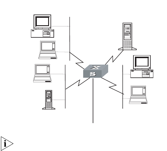
214 CHAPTER 7: QOS/ACL OPERATION
Figure 1 Networking for advanced ACL configuration
Only the commands concerning ACL configuration are listed here.
1Define the time range from 8:00 to 18:00.
[SW8800]time-range 3com 8:00 to 18:00 working-day
2Define inbound traffic to the wage server.
Create a name-based advanced ACL "traffic-of-payserver" and enter it.
[SW8800]acl name traffic-of-payserver advanced
Define ACL rule for other departments.
[SW8800-acl-adv-traffic-of-payserver]rule 1 deny ip source any
destination 129.110.1.2 0.0.0.0 time-range 3com
Define an ACL rule for CEO's office.
[SW8800-acl-adv-traffic-of-payserver]rule 2 permit ip source
129.111.1.2 0.0.0.0 destination 129.110.1.2 0.0.0.0
3Activate the ACL "traffic-of-payserver".
[SW8800-GigabitEthernet2/1/1]packet-filter inbound ip-group
traffic-of-payserver
Basic ACL Configuration
Example
With proper basic ACL configuration, during the time range from 8:00 to 18:00
everyday the switch filters the packets from the host with source IP 10.1.1.1 (the
host is connected through the port GigabitEthernet2/1/1 to the switch.)
Administrative Dept
Financial Dept
President's office
129.111.1.2 Wage server
129.110.1.2
Switch
#1
#4
#3
#2
To router
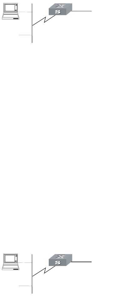
ACL Configuration Example 215
Figure 2 Networking for basic ACL configuration
Only the commands concerning ACL configuration are listed.
1Define the time range from 8:00 to 18:00.
[SW8800]time-range 3com 8:00 to 18:00 daily
2Define the traffic with source IP 10.1.1.1.
Create a name-based basic ACL "traffic-of-host" and enter it.
[SW8800]acl name traffic-of-host basic
Define ACL rule for source IP 10.1.1.1.
[SW8800-acl-basic-traffic-of-host]rule 1 deny ip source 10.1.1.1 0
time-range 3com
3Activate the ACL "traffic-of-host".
[SW8800-GigabitEthernet2/1/1]packet-filter inbound ip-group
traffic-of-host
L2 ACL Configuration
Example
With proper L2 ACL configuration, during the time range from 8:00 to 18:00
everyday the switch filters the packets with source MAC 00e0-fc01-0101 and
destination MAC 00e0-fc01-0303 (configuring at the port GigabitEthernet2/1/1 to
the switch.)
Figure 3 Networking for L2 ACL Configuration
Only the commands concerning ACL configuration are listed.
1Define the time range from 8:00 to 18:00.
[SW8800]time-range 3com 8:00 to 18:00 daily
2Define the traffic with source MAC 00e0-fc01-0101 and destination MAC
00e0-fc01-0303.
Create a name-based L2 ACL "traffic-of-link" and enter it.
[SW8800]acl name traffic-of-link link
Switch
#1 To router
Switch
#1 To router

216 CHAPTER 7: QOS/ACL OPERATION
Define ACL rule for the traffic with source MAC 00e0-fc01-0101 and destination
MAC 00e0-fc01-0303.
[SW8800-acl-link-traffic-of-link]rule 1 deny ingress 00e0-fc01-0101
0-0-0 egress 00e0-fc01-0303 0-0-0 time-range 3com
3Activate the ACL "traffic-of-host".
[SW8800-GigabitEthernet2/1/1]packet-filter inbound link-group
traffic-of-link
QoS Configuration In a traditional IP network, all packets are treated equally without priority
difference. Every switch or router handles the packets following the first-in
first-out (FIFO) policy. Switches and routers make their best effort to transmit the
packets to the destination, not making any commitment or guarantee of the
transmission reliability, delay, or to satisfy other performance requirements.
Ethernet technology is currently the most widely used network technology.
Ethernet has been the dominant technology of various independent Local Area
Networks (LANs), and many Ethernet LANs have been part of the Internet. To
implement the end-to-end QoS solution on the whole network, one must consider
how to guarantee Ethernet QoS service. This requires the Ethernet switching
devices to apply Ethernet QoS technology and deliver the QoS guarantee at
different levels to different types of signal transmissions over the networks,
especially those having requirements of shorter time delay and lower jitter.
The following sections describe terms and concepts used when configuring QoS:
Flow
It refers to all packets passing thought the switch.
Traffic classification
Traffic classification is the technology that identifies the packets with a specified
attribute according to a specific rule. Classification rule refers to a packet filtering
rule configured by an administrator. A classification rule can be very simple. For
example, the switch can identify the packets of different priority levels according
to the ToS (type of service) field in the packet headers. It can also be very complex.
For example, it may contain information of the link layer (layer 2), network layer
(layer 3) and transport layer (layer 4) and the switch classifies packets according to
such information as MAC address, IP protocol, source address, destination address
and port ID. Classification rule often is limited to the information encapsulated at
the packet header, rarely using packet contents.
Packet filtering
Packet filtering refers to filtering operation applied to traffic flow. For example, the
deny operation drops the traffic flow which matches the classification rule and
allows other traffic to pass. Switches use complex classification rules, so that traffic
flow can be filtered by varied information, to enhance network security.
There are two key steps in achieving packet filtering:
■Classify the traffic at the port according to a specific rule.
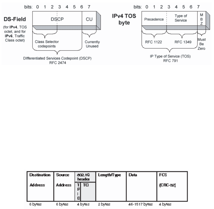
QoS Configuration 217
■Run the filtering operation (deny or permit) to the identified traffic. The default
filtering operation is to deny traffic.
Traffic policing
QoS can police traffic at the ingress port, to provide better services with the limited
network resources.
Redirection
You can re-specify forwarding port for packets, based on QoS policy.
Traffic priority
Switches can provide priority tags, including ToS, DSCP, 802.1p, and so on, for
specific packets. These priority tags are applicable to different QoS models.
Figure 4 illustrates the DS field and TOS byte.
Figure 4 DS Field and ToS Byte
As shown in Figure 4, the ToS field in the IP header contains 8 bits. The first three
bits represent IP priority, in the range of 0 to 7; bits 3-6 stand for ToS priority, in the
range of 0 to 15. RFC2474 redefines the ToS field in IP packets as DS
(differentiated services) field. The first six bits denote DSCP (differentiated services
codepoint) priority, in the range of 0 to 63, the latter two bits are reserved.
802.1p priority is stored in the header of L2 packets and is suitable for a case in
which only L2 QoS guarantee, not L3 header analysis, is required. Figure 5
illustrates an Ethernet frame with the 802.1Q tag header.
Figure 5 Ethernet Frame with 802.1Q Tag Header
In Figure 5, each host supporting 802.1Q protocol adds a 4-byte 802.1Q tag
header after the source address in Ethernet header.
The 802.1Q tag header contains a 2-byte TPID (Tag protocol Identifier, with the
value 8100) and a 2-byte TCI (tag control information). TPID is newly defined by
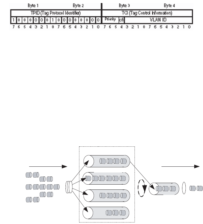
218 CHAPTER 7: QOS/ACL OPERATION
IEEE to represent a packet with 802.1Q tag added. The contents of 802.1Q tag
header are shown in Figure 6.
Figure 6 802.1Q Tag Header
In the figure, the priority field in TCI stands for 802.1p priority, which consists of
three bits. There are eight priority levels, numbered as 0 to 7, for determining
which packets to send first when switch congestion takes place.
Since their applications are defined in detail in the 802.1p Recommendation, they
are named as 802.1p priority levels.
Queue Scheduling
Queue scheduling is used to resolve problems of resource contention by many
packets. The strict priority (SP) and weighted round robin (WRR) algorithms are
often used in queue scheduling.
Figure 7 Priority Queues
SP algorithm The SP algorithm is designed for key services. One of the
characteristics of key services is these services should be processed first to
minimize response delay during switch congestion. For example, there are eight
outbound queues at the port, numbered respectively as 7~0, with priority levels in
descending order.
In SP mode, the system first sends those packets of higher priority in strict
accordance with priority order. Only when packets in high priority queue are all
sent can those in lower priority queue be sent. This manner of putting key-service
packets into high priority queue and non-key service packets into low priority
queue does ensure that key-service packets are sent first, while non-key service
packets are sent during the interval when no key-service packets needs to be
processed.
SP algorithm also has its disadvantages: If high priority queues always have
packets for a long period, then the packets in low queues may die of hunger for
being processed.
Packets sent through
this interface
Classify
Packets sent
Sending queue
Dequeue
high queue
middle queue
normal queue
bottom queue
QoS Configuration 219
WRR algorithm Each port supports four or eight outbound queues. In WRR
mode, the system processes the queues by turn, so every queue can have a service
period.
See the case where the port supports four outbound queues. Every queue is
assigned with a weight value (respectively numbered as w3, w2, w1 and w0),
which indicates the weight in obtaining resources. For a 100 Mbps port, the
weight values are set as 50, 30, 10 and 10 (corresponding respectively to w3, w2,
w1 and w0). The even the queue with the lowest priority can be allocated with a
10 Mbps bandwidth.
Another merit for WRR algorithm: Though the queues are scheduled by turn, they
are not configured with fixed time quantum. If a queue has no packets, the system
immediately schedules the next queue. Then bandwidth resources can be fully
utilized.
Traffic mirroring
Traffic mirroring duplicates specified packets to the monitoring port for network
test and troubleshooting.
Port mirroring
Port mirroring duplicates all packets at a specified port to the monitoring port for
network test and troubleshooting.
Flow-based traffic statistics
The system can make traffic statistics based on flow for further analysis.
QoS Configuration QoS configuration tasks include
■Configuring Packet Filtering
■Configuring the Service Parameter Allocation Rule
■Configuring Traffic Policing
■Configuring Mapping Tables
■Configuring Traffic Shaping
■Configuring Traffic Priority
■Configuring Traffic Redirection
■Configuring Queue Scheduling
■Configuring WRED Parameters
■Configuring the Drop Algorithm
■Configuring Traffic Mirroring
■Configuring Port Mirroring
■Configuring Traffic Statistics
■Displaying and Debugging the QoS Configuration

220 CHAPTER 7: QOS/ACL OPERATION
Configuring Packet Filtering
Before initiating any of these QoS configuration tasks, you should first define the
corresponding ACL. Then you can achieve packet filtering just by activating the
right ACL.
Some of QoS terms are listed in the following table.
Configuring the Service Parameter Allocation Rule
QoS is based on service parameters, a set of parameters for a packet, including
802.1p priority (CoS priority), DSCP priority, local precedence and drop
precedence.
After receiving a packet, the switch allocates a set of service parameters to it
according to a specific rule. The switch first gets its local precedence and drop
precedence according to the packet 802.1p priority value, by searching in the CoS
-> Local-precedence mapping table and the CoS -> Drop-precedence mapping
table. Default values are available for the two mapping tables, but you can also
configure the mapping tables according to your needs. If the switch cannot
allocate local precedence for the packet, it uses the default local precedence of the
port for the packet. After obtaining packet local precedence, the switch then gets
drop precedence according to the CoS -> Drop-precedence mapping table (local
precedence value is used as CoS value in this process).
Configuring the Mapping Table Perform the following configurations in
system view.
Tab le 11 QoS Terms
Term Description
CoS Means the same as 802.1p priority. Both refer to the priority at packet
header, with the value ranging from 0 to 7.
Service parameters Switch allocates a set of parameters, which are used in achieving QoS
functions, upon receiving a packet. Four items are included: 802.1p
priority, DSCP priority, local precedence and drop precedence.
Drop-precedence One of the service parameters, ranging from 0 to 2. Drop precedence is
allocated when the switch receives the packet and may be when the
packet is processed. Allocating drop precedence to the packet is also
called coloring the packet: the packet with drop precedence 2 as red,
that with drop precedence 1 as yellow and that with drop precedence 0
as green. Drop precedence is referred to when switch needs to drop
packets when it is congested
Conform-level The result calculated by the user-defined CIR, CBS, EBS, PIR and actual
traffic when the switch runs traffic policing, in the range of 0 to 2. It is
used as a parameter in the traffic-limit command (here the value
depends on the calculated result). It is also involved in the DSCP +
Conform level —> Service parameter mapping table which is used in
re-allocating service parameters to a packet with the traffic-priority
command. Then Conform-Level must be 0.
Tab le 12 Configuring Mapping Tables
Operation Command
Configure the CoS -> Drop-precedence
mapping table
qos cos-drop-precedence-map
cos0-map-drop-prec cos1-map-drop-prec
cos2-map-drop-prec cos3-map-drop-prec
cos4-map-drop-prec cos5-map-drop-prec
cos6-map-drop-prec cos7-map-drop-prec

QoS Configuration 221
By default, the switch obtains local precedence and drop precedence according to
the default mapping values.
Configuring Default Local Precedence for a Port Perform the following
configuration in Ethernet interface view.
Configuring Traffic Policing
Traffic policing refers to the rate limit based on traffic. If the traffic threshold is
exceeded, corresponding measures will be taken, for example, dropping the
excessive packets or re-defining their priority levels.
In the traffic supervision action, the switch uses the service parameters allocated
according to the DSCP + Conform-Level -> Service parameter mapping table and
the 802.1p priority values allocated according to the Local-precedence +
Conform-Level -> 802.1p priority mapping table. So you should configure these
two mapping tables or use their default values.
Perform the following configurations in Ethernet interface or VLAN view.
Restore the default values of CoS ->
Drop-precedence mapping table
undo qos cos-drop-precedence-map
Configure the CoS -> Local-precedence
mapping table
qos cos-local-precedence-map
cos0-map-local-prec cos1-map-local-prec
cos2-map-local-prec cos3-map-local-prec
cos4-map-local-prec cos5-map-local-prec
cos6-map-local-prec cos7-map-local-prec
Restore the default values of CoS ->
Local-precedence mapping table
undo qos cos-local-precedence-map
Table 13 Configuring Default Local Precedence for a Port
Operation Command
Configuring default local precedence for
a port
priority priority-level
Restore the default value undo priority
Table 14 Configuring Traffic Policing
Operation Command
Configure traffic policing which only
applies IP group ACL
traffic-limit inbound ip-group { acl-number |
acl-name } [ rule rule [ system-index index ] ] [
tc-index index ] cir cbs ebs [ pir ] [ conform { {
remark-cos | remark-drop-priority }* | remark-
policed-service } ] [ exceed { forward | drop } ]
Remove traffic policing setting which
only applies IP group ACL
undo traffic-limit inbound ip-group { acl-number |
acl-name } [ rule rule ]
Configure traffic policing which applies IP
group ACL and link group ACL at same
time
traffic-limit inbound ip-group { acl-number |
acl-name } { rule rule link-group { acl-number |
acl-name } [ rule rule [ system-index index ] ] |
link-group { acl-number | acl-name } rule rule } [
tc-index index ] cir cbs ebs [ pir ] [ conform { {
remark-cos | remark-drop-priority }* | remark-
policed-service } ] [ exceed { forward | drop } ]
Table 12 Configuring Mapping Tables
Operation Command

222 CHAPTER 7: QOS/ACL OPERATION
You must first define the corresponding ACL and configure the DSCP +
Conform-Level -> Service parameters mapping table and Local-precedence +
Conform-Level -> mapping table before beginning this configuration.
This configuration achieves traffic policing for the packets that match the ACL. If
the traffic rate threshold is exceeded, corresponding measures will be taken, for
example, dropping excessive packets.
See the Switch 8800 Command Reference Guide for details of the commands.
Configuring Mapping Tables
Perform the following configurations in the specified views.
The system provides default mapping tables.
Configuring Traffic Shaping
Traffic shaping controls the rate of outbound packets, to ensure they are sent at
relatively average rates. Traffic shaping measure tries to match packet transmission
Remove traffic policing setting which
applies IP group ACL and link group ACL
at same time
undo traffic-limit inbound ip-group { acl-number |
acl-name } { rule rule link-group { acl-number |
acl-name } [ rule rule ] | link-group { acl-number |
acl-name } rule rule }
Configure traffic policing which only
applies link group ACL
traffic-limit inbound link-group { acl-number |
acl-name } [ rule rule [ system-index index ] ] [
tc-index index ] cir cbs ebs [ pir ] [ conform { {
remark-cos | remark-drop-priority }* | remark-
policed-service } ] [ exceed { forward | drop } ]
Remove traffic policing setting which
only applies link group ACL
undo traffic-limit inbound link-group { acl-number |
acl-name } [ rule rule ]
Tab le 15 Configuring Mapping Tables
Operation Command
Enter conform level view (System view) qos conform-level conform-level-value
Configure the DSCP + Conform-Level ->
Service parameters mapping table
(conform level view)
dscp dscp-list : dscp-value exp-value cos-value
local-precedence-value drop-precedence
Restore the default values of the DSCP +
Conform-Level -> Service parameters
mapping table (conform level view)
undo dscp dscp-list
Configure the EXP + Conform-Level ->
Service parameters mapping table
(conform level view)
exp exp-list : dscp-value exp-value cos-value
local-precedence-value drop-precedence
Restore the default values of the EXP +
Conform-Level -> Service parameters
mapping table (conform level view)
undo exp exp-list
Configure the Local-precedence +
Conform-Level -> mapping table
(conform level view)
local-precedence cos-value0 cos-value1
cos-value2 cos-value3 cos-value4 cos-value5
cos-value6 cos-value7
Restore the default values of the
Local-precedence + Conform-Level ->
mapping table (conform level view)
undo local-precedence
Table 14 Configuring Traffic Policing
Operation Command

QoS Configuration 223
rate with the capacity of downstream devices. Its major difference from traffic
policing is: Traffic shaping buffers packets at over-threshold rates to make them
sent at average rates, while traffic policing drops excessive packets. Therefore,
traffic shaping may increase transmission delay, but not for traffic policing.
Perform the following configurations in Ethernet interface view.
The switch supports traffic shaping based on the port, that is, all traffic on the port
is shaped. It also supports traffic shaping for a specific queue. You can choose to
achieve one of them by selecting different parameters in the command.
See the Switch 8800 Command Reference Guide for details of the commands.
Configuring Traffic Priority
This configuration re-labels priority value for the packets that match the ACL. The
switch may allocate new service parameters by searching the mapping tables
according to the DSCP values. You can customize a set of service parameters.
Perform the following configurations in Ethernet interface or VLAN view.
Table 16 Configuring Traffic Shaping
Operation Command
Configure traffic shaping traffic-shape [ queue queue-id ] max-rate
burst-size
Remove traffic shaping setting undo traffic-shape [ queue queue-id ]
Table 17 Configuring Traffic Priority
Operation Command
Configure traffic priority which only
applies IP group ACL
traffic-priority inbound ip-group { acl-number |
acl-name } [ rule rule [ system-index index ] ] {
auto | remark-policed-service { trust-dscp | dscp
dscp-value | untrusted dscp dscp-value cos
cos-value local-precedence local-precedence
drop-priority drop-level } }
Remove traffic priority setting which only
applies IP group ACL
undo traffic-priority inbound ip-group {
acl-number | acl-name } [ rule rule ]
Configure traffic priority which applies IP
group ACL and link group ACL at same
time
traffic-priority inbound ip-group { acl-number |
acl-name } { rule rule link-group { acl-number |
acl-name } [ rule rule [ system-index index ] ] |
link-group { acl-number | acl-name } rule rule } {
auto | remark-policed-service { trust-dscp | dscp
dscp-value | untrusted dscp dscp-value cos
cos-value local-precedence local-precedence
drop-priority drop-level } }
Remove traffic priority setting which
applies IP group ACL and link group ACL
at same time
undo traffic-priority inbound ip-group {
acl-number | acl-name } { rule rule link-group {
acl-number | acl-name } [ rule rule ] | link-group {
acl-number | acl-name } rule rule }
Configure traffic priority which only
applies link group ACL
traffic-priority inbound link-group { acl-number |
acl-name } [ rule rule [ system-index index ] ] {
auto | remark-policed-service { trust-dscp | dscp
dscp-value | untrusted dscp dscp-value cos
cos-value local-precedence local-precedence
drop-priority drop-level } }

224 CHAPTER 7: QOS/ACL OPERATION
You must first define the corresponding ACL and configure the DSCP +
Conform-Level -> Service parameters mapping table before starting this
configuration.
The DSCP + Conform-Level 0 -> Service parameters mapping table (the mapping
table for conform level 0) is used here.
See the Switch 8800 Command Reference Guide for details of the commands.
Configuring Traffic Redirection
Traffic redirection changes the packet forwarding direction, to CPU, other ports,
other IP or segment addresses.
Perform the following configurations in Ethernet interface or VLAN view.
Traffic redirection setting is only available for the permitted rules in the ACL.
The packet redirected to the CPU cannot be forwarded normally.
You can achieve policy route by selecting the next-hop keyword.
See the Switch 8800 Command Reference Guide for details of the commands.
Remove traffic priority setting which only
applies link group ACL
undo traffic-priority inbound link-group {
acl-number | acl-name } [ rule rule ]
Tab le 18 Configuring Traffic Redirection
Operation Command
Configure traffic redirection which only
applies IP group ACL
traffic-redirect inbound ip-group { acl-number |
acl-name } [ rule rule [ system-index index ] ] { cpu
| interface { interface-name | interface-type
interface-num } destination-vlan { l2-vpn | l3-vpn } |
next-hop ip-addr1 ip-addr2 }
Remove traffic redirection setting which
only applies IP group ACL
undo traffic-redirect inbound ip-group {
acl-number | acl-name } [ rule rule ]
Configure traffic redirection which
applies IP group ACL and link group ACL
at same time
traffic-redirect inbound ip-group { acl-number |
acl-name } { rule rule link-group { acl-number |
acl-name } [ rule rule [ system-index index ] ] |
link-group { acl-number | acl-name } rule rule } {
cpu | interface { interface-name | interface-type
interface-num } destination-vlan { l2-vpn | l3-vpn } |
next-hop ip-addr1 ip-addr2 }
Remove traffic redirection setting which
applies IP group ACL and link group ACL
at same time
undo traffic-redirect inbound ip-group {
acl-number | acl-name } { rule rule link-group {
acl-number | acl-name } [ rule rule ] | link-group {
acl-number | acl-name } rule rule }
Configure traffic redirection which only
applies link group ACL
traffic-redirect inbound link-group { acl-number
| acl-name } [ rule rule [ system-index index ] ] {
cpu | interface { interface-name | interface-type
interface-num } destination-vlan { l2-vpn | l3-vpn } |
next-hop ip-addr1 [ ip-addr2 ] }
Remove traffic redirection setting which
only applies link group ACL
undo traffic-redirect inbound link-group {
acl-number | acl-name } [ rule rule ]
Table 17 Configuring Traffic Priority
Operation Command

QoS Configuration 225
Configuring Queue Scheduling
The switch supports eight outbound queues at a port and it puts the packets into
the queues according to the local precedence of packets. Queue scheduling is
used to resolve problems of resource contention by many packets. The switch
supports SP algorithm and WRR algorithm.
Different outbound queues at the port can use different algorithms. The switch
supports three scheduling modes:
■All-SP scheduling
■All-WRR: The outbound queues are divided into WRR queue 1 and WRR queue
2. The switch first schedules the queues in the WRR queue1. If no packets are
waiting for being forwarded in WRR queue 1, then it begins to schedule the
queues in WRR queue 2. By default, all queues at a port are in WRR queue 1.
■SP plus WRR: The outbound queues are put into different scheduling groups.
An SP group uses SP algorithm, WRR groups use WRR algorithm. The select
one queue respectively from SP group, WRR group 1 and WRR group 2 and
schedule them using the SP algorithm.
Perform the following configurations in Ethernet interface view.
By default, the switch uses all-SP mode, so those queues not configured with WRR
algorithm are SP mode.
See the Switch 8800 Command Reference Guide for details of the commands.
Configuring WRED Parameters
When there is network congestion, the switch drops packets to release system
resources so no packets are put into long-delay queues.
The switch allocates drop precedence for it when receiving a packet (also called
coloring the packet). The drop precedence values range from 0 to 2, with 2 for
red, 1 for yellow and 0 for green. In congestion, red packets will be first dropped,
and green packets last.
You can configure drop parameters and thresholds by queue or drop precedence.
The following two drop modes are available:
■Tail drop mode: Different queues (red, yellow and red) are allocated with
different drop thresholds. When these thresholds are exceeded respectively,
excessive packets will be dropped.
■WRED drop mode: Drop precedence is taken into account in drop action.
When only min-thresholds of red, yellow and green packets are exceeded,
excessive packets are dropped randomly at given probability. But when
Table 19 Configuring Queue Scheduling
Operation Command
Configuring queue scheduling queue-scheduler wrr { group1 { queue-id
queue-weight } &<1-8> | group2 { queue-id
queue-weight } &<1-8> }*
Restore the default setting undo queue-scheduler [ queue-id ] &<1-8>

226 CHAPTER 7: QOS/ACL OPERATION
max-thresholds of red, yellow and green packets are exceeded, all excessive
packets are dropped.
You must first configure WRED parameters for every outbound queue in defining
drop precedence.
The switch provides four sets of default WRED parameters, respectively numbered
as 0 to 3. Each set includes 80 parameters, 10 parameters for each of the eight
queues. The ten parameters are green-min-threshhold, yellow-min-threshhold,
red-min-threshhold, green-max-threshhold, yellow-max-threshhold,
red-max-threshhold, green-max-prob, yellow-max-prob, red-max-prob and
exponent. Red, yellow and green packets respectively refer to those with drop
precedence levels 2, 1 and 0.
Perform the following configurations in the specified views.
The command restores the parameters of the specified WRED index as the default
setting. The command restores the WRED parameters related to the queue as the
default setting.
The switch provides four sets of WRED parameters by default.
See the Switch 8800 Command Reference Guide for details of the commands.
Configuring the Drop Algorithm
Perform the following configurations in Ethernet port view.
By default, tail drop mode is selected.
See the corresponding Command Manual for details of the commands.
Tab le 20 Configuring WRED parameters
Operation Command
Enter WRED index view (system view) wred wred-index
Restore the default WRED parameters
(system view)
undo wred wred-index
Configure WRED parameters (WRED
index view)
queue queue-id green-min-threshold
green-max-threshold green-max-prob
yellow-min-threshold yellow-max-threshold
yellow-max-prob red-min-threshold
red-max-threshold red-max-prob exponent
Restore the default WRED parameters
(WRED index)
undo queue queue-id
Exit WRED index view (WRED index view) quit
Tab le 21 Configuring the Drop Algorithm
Operation Command
Configure drop algorithm drop-mode { tail-drop | wred } [ wred-index ]
Restore the default algorithm undo drop-mode

QoS Configuration 227
Configuring Traffic Mirroring
Traffic mirroring duplicates the traffic that matches ACL rules to the CPU, for
traffic analysis and monitoring.
Perform the following configurations in Ethernet interface or VLAN view.
See the Switch 8800 Command Reference Guide for details of the commands.
Configuring Port Mirroring
Port mirroring duplicates data on the monitored port to the designated monitoring
port, for purpose of data analysis and supervision. The switch supports
multiple-to-one mirroring, that is, you can duplicate packets from multiple ports to
a monitoring port.
You can also specify the monitoring direction:
■Only inbound packets
■Only outbound packets
Perform the following configurations in system view.
You can implement a port mirroring configuration by setting mirroring groups at
the port. Up to 20 mirroring groups can be configured at a port, with each group
including one monitoring port and multiple monitored ports.
The limit of port mirroring configuration:
Table 22 Configuring Traffic Mirroring
Operation Command
Configure traffic mirroring which only
applies IP group ACL
mirrored-to inbound ip-group { acl-number |
acl-name } [ rule rule [ system-index index ] ] cpu
Remove traffic mirroring setting which
only applies IP group ACL
undo mirrored-to inbound ip-group {
acl-number | acl-name } [ rule rule ]
Configure traffic mirroring which applies
IP group ACL and link group ACL at same
time
mirrored-to inbound ip-group { acl-number |
acl-name } { rule rule link-group { acl-number |
acl-name } [ rule rule [ system-index index ] ] |
link-group { acl-number | acl-name } rule rule } cpu
Remove traffic mirroring setting which
applies IP group ACL and link group ACL
at same time
undo mirrored-to inbound ip-group {
acl-number | acl-name } { rule rule link-group {
acl-number | acl-name } [ rule rule ] | link-group {
acl-number | acl-name } rule rule }
Configure traffic mirroring which only
applies link group ACL
mirrored-to inbound link-group { acl-number |
acl-name } [ rule rule [ system-index index ] ] cpu
Remove traffic mirroring setting which
only applies link group ACL
undo mirrored-to inbound link-group {
acl-number | acl-name } [ rule rule ]
Table 23 Configuring Port Mirroring
Operation Command
Configure port mirroring mirroring-group groupId { inbound | outbound }
mirroring-port-list &<1-8> mirrored-to
mornitor-port
Remove port mirroring setting undo mirroring-group groupId

228 CHAPTER 7: QOS/ACL OPERATION
■The monitor port and the monitored ports must be the ports in the same
interface card.
■Only one mirror group can be configured on one interface card for one
direction mirror. For example, only one inbound direction mirror group can be
configured on an interface card. If user configures another inbound direction
mirror group, the system will give configure failure prompt. So does the
outbound direction mirror group.
See the Switch 8800 Command Reference Guide for details of the commands.
Configuring Traffic Statistics
Traffic statistics count packets of designated service traffic, that is, the packets
match the defined ACL among those forwarded. You can view the information
with the display qos-interface traffic-statistic command.
Perform the following configurations in Ethernet port or VLAN view.
See the Switch 8800 Command Reference Guide for details of the commands.
Displaying and Debugging the QoS Configuration
After these configurations are completed, you can use the display command in
any view to view QoS running and check configuration result. You can clear QoS
statistics using the display command in Ethernet interface view.
Tab le 24 Configuring traffic statistics
Operation Command
Configure traffic statistics which only
applies IP group ACL
traffic-statistic inbound ip-group { acl-number |
acl-name } [ rule rule [ system-index index ] ] [
tc-index index ]
Remove traffic statistics setting which
only applies IP group ACL
undo traffic-statistic inbound ip-group {
acl-number | acl-name } [ rule rule ]
Configure traffic statistics which applies
IP group ACL and link group ACL at same
time
traffic-statistic inbound ip-group { acl-number |
acl-name } { rule rule link-group { acl-number |
acl-name } [ rule rule [ system-index index ] ] |
link-group { acl-number | acl-name } rule rule } [
tc-index index ]
Remove traffic statistics setting which
applies IP group ACL and link group ACL
at same time
undo traffic-statistic inbound ip-group {
acl-number | acl-name } { rule rule link-group {
acl-number | acl-name } [ rule rule ] | link-group {
acl-number | acl-name } rule rule }
Configure traffic statistics which only
applies link group ACL
traffic-statistic inbound link-group { acl-number
| acl-name } [ rule rule [ system-index index ] ] [
tc-index index ]
Remove traffic statistics setting which
only applies link group ACL
undo traffic-statistic inbound link-group {
acl-number | acl-name } [ rule rule ]
Display traffic statistics for the port display qos-interface [ interface-name |
interface-type interface-num ] traffic-statistic
Tab le 25 Displaying and Debugging QoS Configurations
Operation Command
Display configuration of QoS actions display qos-global all
Display traffic mirroring configuration of
a port
display qos-interface [ interface-name |
interface-type interface-num ] mirrored-to

Configuration Examples 229
See the Switch 8800 Command Reference Guide for a description of display
information and parameters.
Configuration
Examples
Traffic Policing
Configuration Example
The intranet is connected through 100 Mbps ports between departments and the
wage server is assigned with the IP address 129.110.1.2. The rank and file (VLAN
1) cannot access the wage server during work time (08:30 to 18:00), but other
departments are not limited by this condition. For the wage server, the CIR is 100
kbps, CSB is 2000 bytes and EBS is 3000 bytes.
Display traffic priority configuration of a
port
display qos-interface [ interface-name |
interface-type interface-num ] traffic-priority
Display traffic redirection configuration
of a port
display qos-interface [ interface-name |
interface-type interface-num ] traffic-redirect
Display traffic statistics of a port display qos-interface [ interface-name |
interface-type interface-num ] traffic-statistic
Display port mirroring configuration display mirroring-group [ groupid ]
Display QoS configurations of all ports display qos-interface [ interface-name |
interface-type interface-num ] all
Display traffic limit configuration of a
port
display qos-interface [ interface-name |
interface-type interface-num ] traffic-limit
Display queue scheduling configuration
of a port
display qos-interface [ interface-name |
interface-type interface-num ] queue-scheduler
Display traffic shaping configuration of a
port
display qos-interface [ interface-name |
interface-type interface-num ] traffic-shape
Display the DSCP + Conform-level ->
Service parameter and Local-precedence
+ Conform-level -> 802.1p priority
mapping tables
display qos conform-level [ conform-level-value ]
{ dscp-policed-service-map [ dscp-list ] |
local-precedence-cos-map }
Display the COS -> Drop-precedence
mapping table
display qos cos-drop-precedence-map
Display the COS -> Local-precedence
mapping table
display qos cos-local-precedence-map
Clear traffic statistics reset traffic-statistic inbound { { ip-group {
acl-number | acl-name } rule rule | link-group {
acl-number | acl-name } }* | { ip-group { acl-number
| acl-name } | link-group { acl-number | acl-name }
rule rule }* | ip-group { acl-number | acl-name }
rule rule link-group { acl-number | acl-name } rule
rule }
Table 25 Displaying and Debugging QoS Configurations
Operation Command
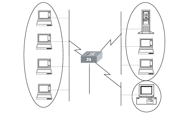
230 CHAPTER 7: QOS/ACL OPERATION
Figure 8 Networking for traffic policing configuration
Only the commands concerning QoS/ACL configuration are listed here.
1Define the time range "worktime" in system view.
[SW8800]time-range worktime 08:30 to 18:00 working-day
2Define the traffic to the wage server.
Create a name-based advanced ACL "traffic-to-payserver" and enter it.
[SW8800]acl name traffic-to-payserver advanced
Define rules for the "traffic-to-payserver" ACL.
[SW8800-acl-adv-traffic-to-payserver]rule 1 deny ip destination
129.110.1.2 0 time-range worktime
3Define the traffic from the wage server.
Create a name-based advanced ACL "traffic-from-payserver" and enter it.
[SW8800]acl name traffic-from-payserver advanced
Define rules for the "traffic-from-payserver" ACL.
[SW8800-acl-adv-traffic-from-payserver]rule 1 permit ip source
129.110.1.2 0
4Limit the rank-and-file's access to the wage server.
The rank-and-file cannot access the wage server during work time, but not limited
at other time. Other groups are also not limited.
[SW8800-vlan1]packet-filter inbound ip-group traffic-to-payserver
rule 1
5Limit outbound traffic from the wage server: CIR is 100 kbps, CBS is 2000 bytes
and EBS is 3000 bytes.
Wage server
129.110.1.2
Switch
To router
Financial Dept.
(vlan2)
The rank and
file (vlan1)
Director
(vlan3)
Wage server
129.110.1.2
Switch
To router
Financial Dept.
(vlan2)
The rank and
file (vlan1)
Director
(vlan3)
Wage server
129.110.1.2
Switch
To router
Financial Dept.
(vlan2)
The rank and
file (vlan1)
Director
(vlan3)
Configuration Examples 231
[SW8800-vlan2]traffic-limit inbound ip-group traffic-from-payserver
rule 1 100 2000 3000
Traffic Shaping
Configuration Example
Set traffic shaping for the outbound queue 2 at the port GE7/1/8: maximum rate
500kbps, burst size 12k bytes.
Figure 9 Networking for QoS Configuration
1Enter Ethernet interface GigabitEthernet7/1/8 view.
[SW8800]interface GigabitEthernet7/1/8
[SW8800-GigabitEthernet7/1/8]
2Set traffic shaping for the outbound queue 2 at the port: maximum rate 650kbps,
burst size 8kbytes, maximum queue length 80kbytes.
[SW8800-GigabitEthernet7/1/8]traffic-shape queue 2 500 12
Port Mirroring
Configuration Example
Use one server to monitor the packets of two ports. R&D department is accessed
from the port GE3/1/1 and sales department from the port GE3/1/2. The server is
connected to the port GE3/1/8.
The mirroring port and the mirrored ports must be on the same interface unit.
On one interface unit, only one mirroring group can be configured in one
direction. For example, you can only configure one mirroring group for the
inbound packets on one interface unit. Failure will be prompted if you configure a
second. The same restriction applies to outbound packets.
Figure 10 Networking for a QoS configuration
GE7/1/8
GE7/1/1 GE7/1/2
VLAN2,
1.0.0.1/8 VLAN3,
2.0.0.1/8
PC1 PC2
GE7/1/8
GE7/1/1 GE7/1/2
VLAN2,
1.0.0.1/8 VLAN3,
2.0.0.1/8
PC1 PC2
E3/0/8
E3/0/2
E3/0/1
GE3/1/8
GE3/1/2
GE3/1/1
E3/0/8
E3/0/2
E3/0/1
GE3/1/8
GE3/1/2
GE3/1/1
232 CHAPTER 7: QOS/ACL OPERATION
Define a mirroring group, with the monitoring port as GigabitEthernet3/1/8.
[SW8800]mirroring-group 1 inbound GigabitEthernet3/1/1
GigabitEthernet3/1/2 mirrored-to GigabitEthernet3/1/8
[SW8800]mirroring-group 2 outbound GigabitEthernet3/1/1
GigabitEthernet3/1/2 mirrored-to GigabitEthernet3/1/8
Traffic Priority
Configuration Example
Re-allocate service parameters according to the mapping table for DSCP 63 for the
packets from PC1 (IP 1.0.0.1) during the time range 8:00 to 18:00 everyday.
Figure 11 Networking for a QoS configuration
1Define the time range from 8:00 to 18:00.
[SW8800]time-range 3com 8:00 to 18:00 daily
2Define the traffic from PC1.
Create a number-based basic ACL 2000 and enter it.
[SW8800]acl number 2000
Define ACL rule for the traffic from PC1.
[SW8800-acl-basic-2000]rule 0 permit source 1.0.0.1 0 time-range
3com
3Define the CoS-> Conform-Level mapping table. The switch allocates drop
precedence (all as 0 for the sake of simplification) for them when receiving
packets.
[SW8800]qos cos-drop-precedence-map 0 0 0 0 0 0 0 0
The modified CoS-> Conform-Level mapping table:
GE7/1/8
GE7/1/1 GE7/1/2
VLAN2,
1.0.0.1/8 VLAN3,
2.0.0.1/8
PC1 PC2
GE7/1/8
GE7/1/1 GE7/1/2
VLAN2,
1.0.0.1/8 VLAN3,
2.0.0.1/8
PC1 PC2
Tab le 26 Modified CoS-> Conform-Level Mapping Table
COS Value Drop-precedence
0 0
1 0
2 0
3 0
4 0
5 0
Configuration Examples 233
4Define the DSCP + Conform-Level -> Service parameter mapping table. Allocate a
set of service parameters for the packets from PC1 according the mapping table
for DSCP 63.
[SW8800]qos conform-level 0
[SW8800-conform-level-0]dscp 63 : 32 4 4 4 0
The modified DSCP + Conform-Level -> Service parameter mapping table:
Re-allocate service parameters for the packets from PC1.
Re-allocate service parameters for the packets from PC1.
[SW8800-GigabitEthernet7/1/1]traffic-priority inbound ip-group 2000
dscp 63
Traffic Redirection
Configuration Example
Forward the packets sent from PC1 (IP 1.0.0.1) during the time range from 8:00 to
18:00 every day to the address 2.0.0.1.
Figure 12 Networking for QoS configuration
1Define the time range from 8:00 to 18:00.
[SW8800]time-range 3com3com 8:00 to 18:00 daily
2Define the traffic from PC1.
Create a number-based basic ACL 2000 and enter it.
[SW8800]acl number 2000
Define ACL rule for the traffic from PC1.
6 0
7 0
Table 26 Modified CoS-> Conform-Level Mapping Table
COS Value Drop-precedence
Table 27 Modified DSCP+Conform-Level>Service Parameter Mapping Table
DSCP CL
Policied-
DSCP
Policied-
EXP
Policied-
802.1p
Policied-
Localprec
Policied-Drop
Precedence
63 032 4 4 4 0
GE7/1/8
GE7/1/1 GE7/1/2
VLAN2,
1.0.0.1/8 VLAN3,
2.0.0.1/8
PC1 PC2
GE7/1/8
GE7/1/1 GE7/1/2
VLAN2,
1.0.0.1/8 VLAN3,
2.0.0.1/8
PC1 PC2
234 CHAPTER 7: QOS/ACL OPERATION
[SW8800-acl-basic-2000]rule 0 permit source 1.0.0.1 0 time-range
3com
3Modify the next hop for the packets from PC1.
Define the next hop for the packets from PC1 as 2.0.0.1.
[SW8800-GigabitEthernet7/1/1]traffic-redirect inbound ip-group 2000
rule 0 next-hop 2.0.0.1
Queue Scheduling
Configuration Example
Modify the correspondence between 802.1p priority levels and local priority levels
to change the mapping between 802.1p priority levels and queues so that packets
are put into outbound queues according to the new mapping. Use WRR algorithm
for the queues 0 to 5 at the port GE7/1/1. Set the queues 0, 1 and 2 into WRR
queue 1, with weight respectively as 20, 20 and 30; set the queues 3, 4 and 5 into
WRR queue 2, with weight respectively as 20, 20 and 40. The queues 6 and 7 use
the SP algorithm. See Queue Scheduling for the default mapping.
Figure 13 Networking for QoS configuration
1Re-specify the mapping between 802.1p priority and local precedence.
[SW8800]qos cos-local-precedence-map 7 6 5 4 3 2 1 0
2Use the WRR algorithm for the queues 0 to 5. Set the queues 0, 1 and 2 into WRR
queue 1, with weight respectively as 20, 20 and 30; set the queues 3, 4 and 5 into
WRR queue 2, with weight respectively as 20, 20 and 40. Use SP algorithm for the
queues 6 and 7.
[SW8800-GigabitEthernet7/1/1]queue-scheduler wrr group1 0 20 1 20 2
30 group2 3 20 4 20 5 40
[SW8800]display qos-interface GigabitEthernet7/1/1 queue-scheduler
Tab le 28 802.1p Priority -> Local Precedence Mapping Table
802.1p priority Local precedence
0 7
1 6
2 5
3 4
4 3
5 2
6 1
7 0
GE7/1/8
GE7/1/1 GE7/1/2
VLAN2,
1.0.0.1/8 VLAN3,
2.0.0.1/8
PC1 PC2
GE7/1/8
GE7/1/1 GE7/1/2
VLAN2,
1.0.0.1/8 VLAN3,
2.0.0.1/8
PC1 PC2
Configuration Examples 235
Ethernet7/1/1 Port scheduling:
QID: scheduling-group weight
-----------------------------------
0 : wrr , group1 20
1 : wrr , group1 20
2 : wrr , group1 30
3 : wrr , group2 20
4 : wrr , group2 20
5 : wrr , group2 40
6 : sp 0
7 : sp 0
WRED Parameters
Configuration Example
Set WRED parameters and drop algorithm for packets at the port GE7/1/1:
Configure parameters for WRED 0; outbound queue ID is 7; green-min-threshold
is 150; green-max-threshold is 500; green-max-prob is 5; yellow-min-threshold is
100; yellow-max-threshold is 150; yellow-max-prob is 10; red-min-threshold is 50;
red-max-threshold is 100; red-max-prob is 15; exponent is 10; the port is in WRED
drop mode; import the parameters of WRED 0.
Figure 14 Networking for QoS configuration
1Configure parameters for WRED 0.
[SW8800]wred 0
[SW8800-wred-0]queue 7 150 500 5 100 150 10 50 100 15 10
2Set drop algorithm and thresholds.
Define the port GE7/1/1 in WRED drop mode, set the parameters of WRED 0.
[SW8800-GigabitEthernet7/1/1]drop-mode wred 0
Traffic Statistics
Configuration Example
Suppose the IP address of PC1 is 1.0.0.1 and that of PC2 is 2.0.0.1. The switch is
uplinked through the port GE7/1/8. Count the packets sent from the switch to
PC1 during the time range from 8:00 to 18:00 every day.
GE7/1/8
GE7/1/1 GE7/1/2
VLAN2,
1.0.0.1/8 VLAN3,
2.0.0.1/8
PC1 PC2
GE7/1/8
GE7/1/1 GE7/1/2
VLAN2,
1.0.0.1/8 VLAN3,
2.0.0.1/8
PC1 PC2
236 CHAPTER 7: QOS/ACL OPERATION
Figure 15 Networking for QoS Configuration
1Define the time range from 8:00 to 18:00.
[SW8800]time-range 3com 8:00 to 18:00 daily
2Define the traffic from PC1.
Define ACL rule for the traffic from PC1.
[SW8800]acl number 2000
[SW8800-acl-basic-2000]rule 0 permit source 1.0.0.1 0.0.0.0
time-range 3com
3Count the packets to PC1 and display the result using the display command.
[SW8800-GigabitEthernet7/1/1]traffic-statistic inbound ip-group 2000
rule 0
[SW8800]display qos-interface GigabitEthernet7/1/1 traffic-statistic
Configuring Logon
User ACL Control
As switches are used more and more widely over the networks, the issue of
security becomes even more important. The switches provide several logon and
device accessing measures, mainly including TELNET access, SNMP access, and
HTTP access. The security control over the access measures is provided with the
switches to prevent illegal users from logging on to and accessing the devices.
There are two levels of security controls. At the first level, the user connection is
controlled with ACL filter and only the legal users can be connected to the switch.
At the second level, a connected user can log on to the device only if he can pass
the password authentication.
This chapter mainly introduces how to configure the first level security control over
these access measures, that is, how to configure to filter the logon users with ACL.
For detailed description about how to configure the first level security, refer to
"getting started" module of Operation Manual.
Configuring ACL for
Telnet Users
This configuration can filter out malicious or illegal connection requests before
password authentication.
Two steps are included in this configuration:
1Define an ACL
2Import the ACL to control Telnet users
GE7/1/8
GE7/1/1 GE7/1/2
VLAN2,
1.0.0.1/8 VLAN3,
2.0.0.1/8
PC1 PC2
GE7/1/8
GE7/1/1 GE7/1/2
VLAN2,
1.0.0.1/8 VLAN3,
2.0.0.1/8
PC1 PC2
Configuring Logon User ACL Control 237
Defining ACLs
Currently only number-based ACLs can be imported, with the number ranging
from 2000 to 3999.
Perform the following configurations in system view.
You can define multiple rules for an ACL by using the rule command several times.
Importing ACL
You can import a defined ACL in user interface view to achieve ACL control.
Perform the following configurations in system view and user interface view.
See the Switch 8800 Command Reference Guide for details about these
commands.
Currently you can import only the basic ACLs with digit IDs.
Configuration Example Only the Telnet users from 10.110.100.52 and 10.110.100.46 can access the
switch.
Figure 16 ACL Configuration for Telnet Users
1Define a basic ACL.
[SW8800]acl number 2000 match-order config
[SW8800-acl-basic-2000]rule 1 permit source 10.110.100.52 0
Table 29 Defining Basic ACLs
Operation Command
Enter basic ACL (system view) acl { number acl-number | name acl-name basic }
match-order { config | auto }
Define a sub-rule (basic ACL view) rule [ rule-id ] { permit | deny } [ source
source-addr wildcard | any ] [ fragment ] [
time-range name ]
Delete a sub-rule (basic ACL view) undo rule rule-id [ source ] [ fragment ] [
time-range ]
Delete an ACL or all ACLs (system view) undo acl { number acl-number | name acl-name |
all }
Table 30 Importing ACL
Operation Command
Enter user interface view (system view) user-interface [ type ] first-number [ last-number ]
Import the ACL (user interface view) acl acl-number { inbound | outbound }
Internet
Switch

238 CHAPTER 7: QOS/ACL OPERATION
[SW8800-acl-basic-2000]rule 2 permit source 10.110.100.46 0
[SW8800-acl-basic-2000]quit
2Import the ACL.
[SW8800]user-interface vty 0 4
[SW8800-user-interface-vty0-4]acl 2000 inbound
Configuring ACL for
SNMP Users
3Com switches support remote network management (NM) and the user can use
SNMP to access them. Proper ACL configuration can prevent illegal users from
logging onto the switches.
Two steps are included in this configuration:
1Define an ACL
2Import the ACL to control SNMP users
Defining an ACL
Currently only number-based ACLs can be imported, with the number ranging
from 2000 to 2999. See 3.3.1 Defining ACL for detailed configuration.
Importing the ACL
Import the defined ACL into the commands with SNMP community, username and
group name configured, to achieve ACL control over SNMP users.
Perform the following configurations in system view.
SNMP community is one of the features of SNMP v1 and SNMP v2, so you import
the ACL into the commands with SNMP community configured, for the SNMP V1
and SNMP V2.
SNMP username or group name is one of the features of SNMP V2 and above,
therefore you import the ACL into the commands with SNMP username or group
name configured, for the SNMP V2 and above. If you import the ACL into both
features, the switch will filter both features for the users.
Tab le 31 Importing an ACL
Operation Command
Import the defined ACL into the
commands with SNMP community
configured
snmp-agent community { read | write }
community-name [ [ mib-view view-name ] | [ acl
acl-number ] ]*
Import the defined ACL into the
commands with SNMP group name
configured
■snmp-agent group { v1 | v2c } group-name [
read-view read-view ] [ write-view write-view
] [ notify-view notify-view ] [ acl acl-number ]
■snmp-agent group v3 group-name [
authentication | privacy ] [ read-view
read-view ] [ write-view write-view ] [
notify-view notify-view ] [ acl acl-number ]
Import the defined ACL into the
commands with SNMP username
configured
■snmp-agent usm-user { v1 | v2c } user-name
group-name [ acl acl-number ]
■snmp-agent usm-user v3 user-name
group-name [ authentication-mode { md5 |
sha } auth-password ] [ privacy-mode des56
priv-password ] [ acl acl-number ]
Configuring Logon User ACL Control 239
You can import different ACLs in the three commands listed above.
See the Switch 8800 Command Reference Guide for details about these
commands.
Currently you can import only the basic ACLs with digit IDs.
Configuration Example Only SNMP users from 10.110.100.52 and 10.110.100.46 can access the switch.
Figure 17 ACL configuration for SNMP users
1Define a basic ACL.
[SW8800]acl number 2000 match-order config
[SW8800-acl-baisc-2000]rule 1 permit source 10.110.100.52 0
[SW8800-acl-baisc-2000]rule 2 permit source 10.110.100.46 0
[SW8800-acl-baisc-2000]quit
2Import the ACL.
[SW8800]snmp-agent community read 3com acl 2000
[SW8800]snmp-agent group v2c 3comgroup acl 2000
[SW8800]snmp-agent usm-user v2c 3comuser 3comgroup acl 2000
Internet
Switch
240 CHAPTER 7: QOS/ACL OPERATION

8STP OPERATION
This chapter covers the following topics:
■STP Overview
■Configuring STP
■MSTP Overview
■Configuring MSTP
STP Overview Spanning Tree Protocol (STP), defined by IEEE 802.1D, is applied in a loop network
to block undesirable redundant paths. Using STP avoids the proliferation and
infinite cycling of a packet in a loop network.
The fundamental feature of STP is that the switches exchange packets called
configuration Bridge Protocol Data Units, or BPDU, to decide the topology of the
network. The configuration BPDU contains the information that ensures that
switches can compute the spanning tree.
The configuration BPDU contains the following information:
■The root ID consisting of root priority and MAC address
■The cost of the shortest path to the root
■A designated switch ID consisting of designated switch priority and MAC
address
■A designated port ID consisting of port priority and port number
■The age of the configuration BPDU (MessageAge)
■The maximum age of the configuration BPDU (MaxAge)
■A configuration BPDU interval (HelloTime)
■A forward delay of the port (ForwardDelay)
Configuring STP STP configuration is described in the following sections:
■Designating Switches and Ports
■Calculating the STP Algorithm
■Generating the Configuration BPDU
■Selecting the Optimum Configuration BPDU
■Designating the Root Port
■Configuring the BPDU Forwarding Mechanism
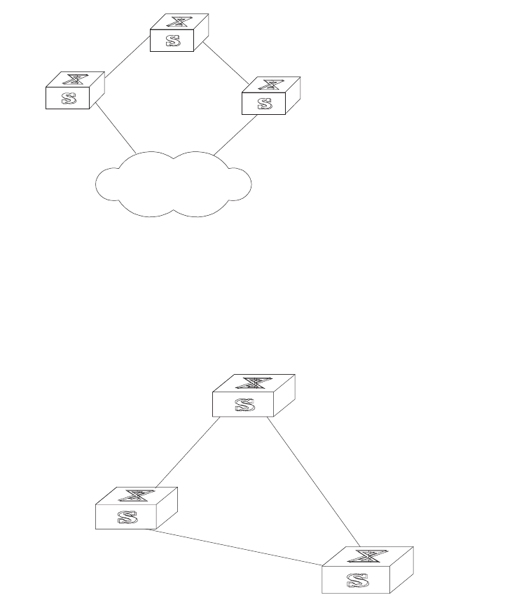
242 CHAPTER 8: STP OPERATION
Designating Switches
and Ports
A designated switch is a switch in charge of forwarding packets to the local switch
by a port called the designated port. For a LAN, the designated switch is a switch
that forwards packets to the network segment by the designated port.
As illustrated in Figure 1, Switch A forwards data to Switch B through
GigabitEthernet port1/1/1. So to Switch B, the designated switch is Switch A and
the designated port is GigabitEthernet1/1/1 of Switch A. Also, Switch B and
Switch C are connected to the LAN and Switch B forwards packets to the LAN. So
the designated switch of LAN is Switch B and the designated port is
GigabitEthernet1/1/4 of Switch B.
Figure 1 Designated Switch and Designated Port
Calculating the STP
Algorithm
The following example illustrates the calculation process of STP.
The figure1-2 below illustrates the network.
Figure 2 Switch 8800 Networking
To facilitate the descriptions, only the first four parts of the configuration BPDU are
given in the example. They are root ID (expressed as Ethernet switch priority), path
cost to the root, designated switch ID (expressed as Ethernet switch priority) and
the designated port ID (expressed as the port number). As illustrated in the figure
above, the priorities of Switch A, B and C are 0, 1, and 2 and the path costs of
their links are 5, 10, and 4.
Switch A
Switch C
Switch B
LAN
E1/1/1
E1/1/7
E1/1/4
E1/1/2
E1/1/5
E1/1/1
Switch A
with priority 0
S
witch B
w
ith priority 1
Switch C
with priority
2
E1/1/5
E1/1/2
E1/1/1
E1/1/1
E1/1/7
E1/1/4 4
510
Configuring STP 243
Generating the
Configuration BPDU
When initialized, each port of the switches will generate the configuration BPDU
taking itself as the root, root path cost as 0, designated switch IDs as their own
switch IDs, and the designated ports as their ports.
■Switch A
Configuration BPDU of GigabitEthernet1/1/1: {0, 0, 0, e1/1/1}
Configuration BPDU of GigabitEthernet1/1/2: {0, 0, 0, e1/1/2}
■Switch B
Configuration BPDU of GigabitEthernet1/1/7: {1, 0, 1, e1/1/7}
Configuration BPDU of GigabitEthernet1/1/4: {1, 0, 1, e1/1/4}
■Switch C
Configuration BPDU of GigabitEthernet1/1/1: {2, 0, 2, e1/1/1}
Configuration BPDU of GigabitEthernet1/1/5: {2, 0, 2, e1/1/5}
Selecting the Optimum
Configuration BPDU
Every switch transmits its configuration BPDU to others. When a port receives a
configuration BPDU with a lower priority than that of its own, it will discard the
message and keep the local BPDU unchanged. When a higher-priority
configuration BPDU is received, the local configuration BPDU will be updated.
The optimum configuration BPDU will be elected through comparing the
configuration BPDUs of all the ports.
The comparison rules are:
■The configuration BPDU with a smaller root ID has a higher priority
■If the root IDs are the same, perform the comparison based on root path costs.
The cost comparison is as follows: the path cost to the root recorded in the
configuration BPDU plus the corresponding path cost of the local port is set as
X, the configuration BPDU with a smaller X has a higher priority.
■If the costs of a path to the root are the same, compare, in sequence, the
designated switch ID, designated port ID, and the ID of the port through which
the configuration BPDU was received.
Designating the Root
Port
On a bridge, the port receiving the optimum configuration BPDU is considered the
root port whose configuration BPDU remains the same. Any other port, whose
configuration BPDU has been updated, as explained in “Selecting the Optimum
Configuration BPDU”, will be blocked and will not forward any data. In addition,
any other port only receives, but does not retransmit, a BPDU and its BPDU
remains the same.
On other bridges, a port whose BPDU has not been updated is called the
designated port. Its configuration BPDU is modified by substituting:
■The root ID with the root ID in the configuration BPDU of the root port
■The cost of path to root with the value made by the root path cost, plus the
path cost corresponding to the root port
■The designated switch ID with the local switch ID
■The designated port ID with the local port ID
244 CHAPTER 8: STP OPERATION
The comparison process of each switch is:
■Switch A
GigabitEthernet1/1/1 receives the configuration BPDU from Switch B and finds
out that the local configuration BPDU priority is higher than that of the
received one, so it discards the received configuration BPDU.
The configuration BPDU is processed on the GigabitEthernet1/1/2 in a similar
way. Thus, Switch A finds itself the root and designated switch in the
configuration BPDU of every port; it regards itself as the root, retains the
configuration BPDU of each port and transmits configuration BPDU to others
regularly thereafter. By now, the configuration BPDUs of the two ports are as
follows:
Configuration BPDU of GigabitEthernet1/1/1: {0, 0, 0, e1/1/1}
Configuration BPDU of GigabitEthernet1/1/2: {0, 0, 0, e1/1/2}
■Switch B
GigabitEthernet1/1/7 receives the configuration BPDU from Switch A and finds
that the received BPDU has a higher priority than the local one, so it updates its
configuration BPDU.
GigabitEthernet1/1/4 receives the configuration BPDU from Switch C and finds
that the local BPDU priority is higher than that of the received one, so it
discards the received BPDU.
By now the configuration BPDUs of each port are as follows:
Configuration BPDU of GigabitEthernet1/1/7: {0, 0, 0, e1/1/1}
Configuration BPDU of GigabitEthernet1/1/4: {1, 0, 1, e1/1/4}
Switch B compares the configuration BPDUs of the ports and selects the
GigabitEthernet1/1/7 BPDU as the optimum one. Thus, GigabitEthernet1/1/7 is
elected as the root port and the configuration BPDUs of Switch B ports are
updated as follows.
The configuration BPDU of the root port GigabitEthernet1/1/7 remains {0, 0, 0,
e1/1/1}. GigabitEthernet1/1/4 updates the root ID with the root ID in the
optimum configuration BPDU, updates the path cost to root with 5, sets the
designated switch as the local switch ID and the designated port ID as the local
port ID. Thus, the configuration BPDU becomes {0, 5, 1, e1/1/4}.
All the designated ports of Switch B then transmit the configuration BPDUs
regularly.
■Switch C
GigabitEthernet1/1/1 receives from the GigabitEthernet1/1/4 of Switch B, the
configuration BPDU {1, 0, 1, e1/1/4} that has not been updated, then the
updating process is launched. {1, 0, 1, e1/1/4}.
GigabitEthernet1/1/5 receives the configuration BPDU {0, 0, 0, e1/1/2} from
Switch A, and Switch C launches the updating. The configuration BPDU is
updated as {0, 0, 0, e1/1/2}.
By comparison, the GigabitEthernet1/1/5 configuration BPDU is elected as the
optimum one. The GigabitEthernet1/1/5 is thus specified as the root port with
no modifications made on its configuration BPDU. However,
GigabitEthernet1/1/1 is blocked and its BPDU also remains the same, but it will
not receive the data (excluding the STP packet) forwarded from Switch B until
Configuring STP 245
spanning tree calculation is launched again by new events, for example, the
link from Switch B to C is down or the port receives a better configuration
BPDU.
GigabitEthernet1/1/1 receives the updated configuration BPDU, {0, 5, 1,
e1/1/4}, from Switch B. Since this configuration BPDU is better then the old
one, the old BPDU will be updated to {0, 5, 1, e1/1/4}.
Meanwhile, GigabitEthernet1/1/5 receives the configuration BPDU from Switch
A but its configuration BPDU is not updated and remains {0, 0, 0, e1/1/2}.
By comparison, the configuration BPDU of GigabitEthernet1/1/1 is elected as
the optimum one. GigabitEthernet1/1/1 is elected as the root port, whose
BPDU does not change, while GigabitEthernet1/1/5 is blocked and retains its
BPDU, but it does not receive the data forwarded from Switch A until spanning
tree calculation is triggered again by changes, for example, the link from
Switch B to C is down.
Thus the spanning tree is stabilized. The tree with the root Switch A is
illustrated in Figure 3.
Figure 3 The Final Stabilized Spanning Tree
The root ID and the designated switch ID, in actual calculation, should include
both switch priority and switch MAC address. The designated port ID should
include port priority and port MAC address. In the updating process of a
configuration BPDU, other configuration BPDUs besides the first four items make
modifications according to certain rules. The basic calculation process is described
below.
Configuring the BPDU
Forwarding Mechanism
Upon the initiation of the network, all the switches regard themselves as the roots.
The designated ports send the configuration BPDUs of local ports at a regular
interval of HelloTime. If it is the root port that receives the configuration BPDU, the
switch will enable a timer to time the configuration BPDU, as well as increase
MessageAge carried in the configuration BPDU by certain rules. If a path goes
wrong, the root port on this path will not receive configuration BPDUs anymore,
and the old configuration BPDUs will be discarded due to timeout. Recalculation
of the spanning tree will be initiated to generate a new path to replace the failed
one, and thus restore the network connectivity.
The new configuration BPDU as now recalculated will not be propagated
throughout the network right away, so the old root ports and designated ports,
that have not detected the topology change, will continue to forward the data
Switch A
with priority 0
Switch B
with priority 1 Switch C
with priority 2
4
5
E1/1/7
E1/1/1
E1/1/4
E1/1/1

246 CHAPTER 8: STP OPERATION
through the old path. If the new root port and designated port begin to forward
data immediately after they are elected, a occasional loop may still occur. In RSTP,
a transitional state mechanism is then adopted to ensure the new configuration
BPDU has been propagated throughout the network before the root port and
designated port begin to send data again. That is, the root port and designated
port should undergo a transitional state for a period of Forward Delay before they
enter the forwarding state.
MSTP Overview The Switch 8800 implements the Multiple Spanning Tree Protocol (MSTP), defined
by IEEE 802.1s. MSTP is an enhancement to STP, and is compatible with both STP
and RSTP, defined in IEEE 802.1w. An MSTP switch can recognize both STP and
RSTP packets and can calculate the spanning tree with them. Beside the basic
MSTP functions, the Switch 8800 provides additional MSTP features which include
root bridge hold, secondary root bridge, root protection, and BPDU protection.
STP cannot stabilize a network rapidly. Even on the point-to-point link or the edge
port, it takes an interval as long as twice the forward delay before the network
converges.
MSTP makes the network converge rapidly, and distributes the traffic of different
VLANs along their respective paths. This provides a better load-balance
mechanism for the redundant links.
MSTP associates VLAN with a spanning tree domain, and divides a switching
network into several regions, each of which has a spanning tree independent of
one another. MSTP prunes the network into a loopfree tree to avoid proliferation,
it also provides multiple redundant paths for data forwarding to implement the
VLAN data forwarding load-balance.
Configuring MSTP is described in the following sections:
■MSTP Concepts
■MSTP Principles
MSTP Concepts MSTP Concepts are described in the following sections
■MST Region
■VLAN Mapping Table
■Internal Spanning Tree (IST)
■Common Spanning Tree (CST)
■Common and Internal Spanning Tree (CIST)
■Multiple Spanning Tree Instance (MSTI)
■MSTI Region root
■Common Root Bridge
■Boundary port
■Port role
There are 4 MST regions in Figure 4.
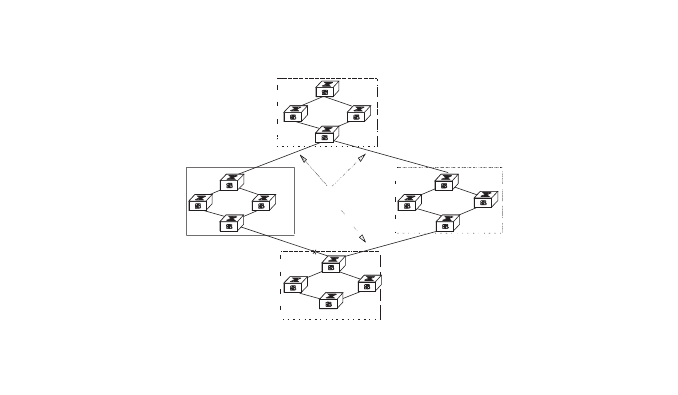
MSTP Overview 247
Figure 4 MSTP Concepts
MST Region
A multiple spanning tree region contains several physically and directly connected
MSTP-capable switches sharing the same region name, VLAN-spanning tree
mapping configuration and MSTP revision level configuration, and the network
segments between them. There can be several MST regions on a switching
network. You can group several switches into a MST region, using MSTP
configuration commands. For example, in Figure 4, in MST region A0, the 4
switches are configured with the same region name, vlan mapping table (VLAN1
map to instance 1, VLAN 2 map to instance 2, other VLAN map to instance 0), and
revision level (not indicated in Figure 4).
VLAN Mapping Table
A VLAN mapping table is an attribute of an MST region and is used for describing
the mapping relationship of VLAN and STI. For example, the VLAN mapping table
of MST region A0 in Figure 4 is VLAN1 map to instance 1, VLAN 2 map to instance
2, other VLAN map to instance 0.
Internal Spanning Tree (IST)
The entire switching network has a Common and Internal Spanning Tree (CIST).
An MSTP region has an Internal Spanning Tree (IST), which is a fragment of CIST.
For example, every MST region in Figure 4 has an IST.
Common Spanning Tree (CST)
CST connects the spanning trees of the MST region. Taking every MST region as a
“switch”, the CST can be regarded as their spanning tree generated with
STP/RSTP. For example, the red line indicates the CST in Figure 4.
Common and Internal Spanning Tree (CIST)
A single spanning tree made of IST and CST. The CIST in Figure 4 is composed of
each IST in every MST region and the CST.
CIST: Common and Internal Spanning Tree
MSTI: Multiple SpanningTree Instance
Region A0
vlan 1 mapped to Instance 1
vlan 2 mapped to Instance 2
Other vlans mapped to CIST
Region B0
vlan 1 mapped to Instance 1
vlan 2 mapped to Instance 2
Other vlans mapped to CIST
Region C0
vlan 1 mapped to Instance 1
vlan 2 and 3 mapped to Instance 2
Other vlans mapped to CIST
Region A0
vlan 1 mapped to Instance 1,
region root B
vlan 2 and 3 mapped to
Instance 2, region root C
Other vlans mapped to CIST
BPDU
BPDU
BPDU
CST: Common
Spanning Tree
A
C
B
D
248 CHAPTER 8: STP OPERATION
Multiple Spanning Tree Instance (MSTI)
Multiple spanning trees can be generated in an MST region and are independent
of one another. Each of these spanning trees is called an MSTI.
MSTI Region root
The MSTI region root refers to the root of the MSTI in an MST region. Each
spanning tree in an MST region can have a different topology with a different
region root.
Common Root Bridge
The common root bridge refers to the root bridge of the CIST. There is only one
common root bridge in the network.
Boundary port
The boundary port refers to the port located at the edge of the MST region. The
boundary port connects different MST regions, an MST region and an STP region,
or an MST region and an RSTP region. For MSTP calculation, the boundary port
has the same role on MSTI and CIST instance. For example, the boundary port as a
master port on a CIST instance should serve as a master port on every MSTI in the
region.
Port role
In the process of MSTP calculation, a port can serve as a designated port, root
port, master port, alternate port, or BACKUP.
■The root port is the port through which the data is forwarded to the root.
■The designated port is the one through which the data is forwarded to the
downstream network segment or switch.
■Master port is the port connecting the entire region to the common root bridge
and located on the shortest path between them.
■An alternate port is the backup of the master port. When the master port is
blocked, the alternate port takes its place.
■If two ports of a switch are connected, there must be a loop. In this case, the
switch will block one of them. The blocked port is called BACKUP port.
A port can play different roles in different spanning tree instances.
Figure 5 illustrates the these concepts.
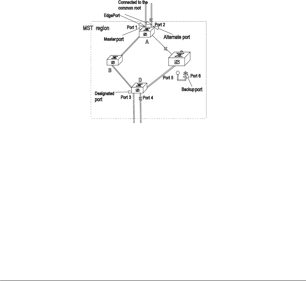
Configuring MSTP 249
Figure 5 Port Roles
MSTP Principles MSTP divides the entire Layer 2 network into several MST regions, and calculates
and generates CST for them. Multiple spanning trees are generated in a region
and each of them is called an MSTI. The instance 0 is called IST, and others are
called MSTI.
CIST calculation
The CIST root is the highest-priority switch, elected from the switches on the entire
network by comparing their configuration BPDUs. MSTP calculates and generates
an IST in an MST region and also the CST connecting the regions. CIST is the
unique single spanning tree of the entire switching network.
MSTI calculation
Inside an MST region, MSTP generates different MSTIs for different VLANs
according to the association between the VLAN and the spanning tree.
In this way, the packets of a VLAN travel along the corresponding MSTI; inside the
MST region and the CST between different regions.
Configuring MSTP Configuring MSTP includes tasks that are described in the following sections:
■Configuring the MST Region for a Switch
■Specifying the Switch as Primary or Secondary Root Switch
■Configuring the MSTP Operating Mode
■Configuring the Bridge Priority for a Switch
■Configuring the Max Hops in an MST Region
■Configuring the Switching Network Diameter
■Configuring the Time Parameters of a Switch
■Configuring the Max Transmission Speed on a Port
■Configuring a Port as an Edge Port

250 CHAPTER 8: STP OPERATION
■Configuring the Path Cost of a Port
■Configuring the Priority of a Port
■Configuring the Port Connection with the Point-to-Point Link
■Configuring the mCheck Variable of a Port
■Configuring the Switch Security Function
■Enabling MSTP on the Device
■Enabling or Disabling MSTP on a Port
■Displaying and Debugging MSTP
Only after MSTP is enabled on the device will other configurations take effect.
Before enabling MSTP, you can configure the related parameters of the device and
Ethernet ports. The configuration of the related parameters and Ethernet ports will
take effect upon enabling MSTP, and stay effective even after resetting MSTP.
The display stp-region-configuration command shows the parameters that are
configured before MSTP is enabled. To display parameters configured after MSTP
is enabled, you can use the related display commands. For detailed information,
see “Displaying and Debugging MSTP”.
You do not have to perform all these tasks to configure MSTP. Many of them are
designed to adjust the MSTP parameters provided with default values. You can
configure these parameters depending on your actual conditions or simply take
the defaults. For more detailed information, refer to the task description or to the
command descriptions in the Switch 8800 Command Reference Guide.
When GVRP and MSTP start up on the switch simultaneously, GVRP packets will
propagate along CIST, which is a spanning tree instance. In this case, if you want
to issue a certain VLAN through GVRP on the network, you should make sure that
the VLAN is mapped to CIST when configuring the VLAN mapping table of MSTP.
CIST is spanning tree instance 0.
Configuring the MST
Region for a Switch The MST region that a switch belongs to is determined with the configurations of
the region name, VLAN mapping table, and MSTP revision level. You can perform
the following configurations to put a switch into an MST region.
Tasks for configuring the MST Region for a Switch is described in the following
sections:
■Entering MST region view
■Configuring the MST Region
■Activating the MST Region Configuration and Exiting the MST Region View
Entering MST region view
Perform the following configuration in system view.
Tab le 1 Enter MST Region View
Operation Command
Enter MST region view (from system view) stp region-configuration
Restore the default settings of MST region undo stp region-configuration

Configuring MSTP 251
Configuring the MST Region
Perform the following configuration in MST region view.
An MST region can contain up to 16 spanning tree instances, among which
Instance 0 is an IST and instances 1 through 16 are MSTIs. Upon the completion of
these configurations, the current switch is put into a specified MST region.
Two switches belong to the same MST region only if they have been configured
with the same MST region name, STI-VLAN mapping tables of an MST region, and
the MST region revision level.
Configuring the related parameters, especially the VLAN mapping table, of the
MST region will lead to the recalculation of spanning tree and network topology
flapping. To reduce such flapping, MSTP triggers to recalculate the spanning tree
according to the configurations only if one of the following conditions are met:
■The user manually activates the configured parameters related to the MST
region, using the active region-configuration command.
■The user enables MSTP, using the stp enable command.
By default, the MST region name is the first switch MAC address, all the VLANs in
the MST region are mapped to the STI 0, and the MSTP region revision level is 0.
You can restore the default settings of MST region, using the undo stp
region-configuration command in system view.
Activating the MST Region Configuration and Exiting the MST Region
View
Perform the following configuration in MST region view.
Specifying the Switch as
Primary or Secondary
Root Switch
MSTP can determine the spanning tree root through calculation. You can also
specify the current switch as the root, using the command provided by the switch.
Table 2 Configure the MST Region for a Switch
Operation Command
Configure MST region name region-name name
Restore the default MST region name undo region-name
Configure VLAN mapping table instance instance-id vlan vlan-list
Restore the default VLAN mapping table undo instance
Configure the MSTP revision level of MST
region
revision-level level
Restore the MSTP revision level of MST region undo revision-level
Table 3 Activate the MST Region Configuration and Exit the MST Region View
Operation Command
Show the configuration information of the
MST region under revision (from MST region
view)
check region-configuration
Manually activate the MST region
configuration (from MST region view)
active region-configuration
Exit MST region view (from MST region view) quit

252 CHAPTER 8: STP OPERATION
You can use the following commands to specify the current switch as the primary
or secondary root of the spanning tree.
Perform the following configuration in system view.
After a switch is configured as primary root switch or secondary root switch, you
cannot modify the bridge priority of the switch.
You can configure the current switch as the primary or secondary root switch of
the STI (specified by the instance instance-id parameter). If the instance-id takes
0, the current switch is specified as the primary or secondary root switch of the
CIST.
The root types of a switch in different STIs are independent of one another. A
switch can be a primary or secondary root of any STI. However, a switch cannot
serve as both the primary and secondary roots of one STI.
If the primary root is down or powered off, unless you configure a new primary
root, the secondary root will take its place. If there are two or more configured
secondary root switches, MSTP selects the one with the smallest MAC address to
take the place of the failed primary root.
When configuring the primary and secondary switches, you can also configure the
network diameter and hello time of the specified switching network. For detailed
information, refer to the configuration tasks “Configuring the Switching Network
Diameter” and “Configuring the Time Parameters of a Switch”.
You can configure the current switch as the root of several STIs, however, it is not
necessary to specify two or more roots for an STI. In other words, please do not
specify the root for an STI on two or more switches.
You can configure more than one secondary root for a spanning tree by specifying
the secondary STI root on two or more switches.
Generally, you are recommended to designate one primary root and more than
one secondary root for a spanning tree.
By default, a switch is neither the primary root or the secondary root of the
spanning tree.
Configuring the MSTP
Operating Mode
MSTP and RSTP are compatible and can recognize each other’s packets. However,
STP cannot recognize MSTP packets. To implement the compatibility, MSTP
provides two operation modes, STP-compatible mode and MSTP mode. In
STP-compatible mode, the switch sends STP packets by every port and serves as a
Tab le 4 Specify the Switch as Primary or Secondary Root Switch
Operation Command
Specify current switch as the primary root
switch of the specified spanning tree.
stp instance instance-id root primary [
bridge-diameter bridgenum [ hello-time
centi-senconds ] ]
Specify current switch as the secondary root
switch of the specified spanning tree.
stp instance instance-id root secondary [
bridge-diameter bridgenum [ hello-time
centi-senconds ] ]
Specify current switch not to be the primary or
secondary root.
undo stp instance instance-id root

Configuring MSTP 253
region itself. In MSTP mode, the switch ports send MSTP or STP packets (when
connected to the STP switch) and the switch provides the multiple spanning tree
function.
You can use the following command to configure the MSTP operational mode.
MSTP can intercommunicate with STP. If there is a STP switch in the switching
network, you can use the command to configure the current MSTP to run in
STP-compatible mode, otherwise, configure it to run in MSTP mode.
Perform the following configuration in system view.
Generally, if there is a STP switch on the switching network, the port connected to
it will automatically transit from MSTP mode to STP-compatible mode. The port
cannot automatically transition itself back to MSTP mode after the STP switch is
removed. In this case, you can perform the mcheck operation to transit the port to
MSTP mode by force.
By default, MSTP runs in MSTP mode.
Configuring the Bridge
Priority for a Switch
Whether or not a switch can be elected as the spanning tree root, depends on its
bridge priority. The switch configured with a lower bridge priority is more likely to
become the root. An MSTP switch can have different priorities in different STIs.
You can use the following command to configure the bridge priorities of the
designated switch in different STIs.
Perform the following configuration in system view.
When configuring the switch priority with the instance instance-id parameter,
with a value of 0, you are configuring the CIST priority of the switch.
In the process of spanning tree root election of two or more switches, with the
lowest priorities, the one has a smaller MAC address will be elected as the root.
By default, the switch priority is 32768.
Configuring the Max
Hops in an MST Region
The scale of an MST region is limited by the max hops in the MST region; which is
configured on the region root. As the BPDU travels from the spanning tree root,
Table 5 Configure the MSTP Operating Mode
Operation Command
Configure MSTP to run in STP-compatible
mode
stp mode stp
Configure MSTP to run in MSTP mode. stp mode mstp
Restore the default MSTP operating mode undo stp mode
Table 6 Configure the Priority for a Switch
Operation Command
Configure the priority of the designated
switch.
stp instance instance-id priority priority
Restore the default priority of the designated
switch.
undo stp instance instance-id priority

254 CHAPTER 8: STP OPERATION
each time it is forwarded by a switch, the max hop is reduced by 1. The switch
discards the configuration BPDU with 0 hops left. This makes it impossible for the
switch beyond the max hops to take part in the spanning tree calculation, thereby
limiting the scale of the MST region.
You can use the following command to configure the max hops in an MST region.
Perform the following configuration in system view.
The more the hops in an MST region, the larger the scale of the region. Only the
max hops configured on the region root can limit the scale of MST region. Other
switches in the MST region also apply the configurations on the region root, even
if they have been configured with max hops.
By default, the max hops of an MST is 20.
Configuring the
Switching Network
Diameter
Any two hosts on the switching network are connected with a specific path
carried by a series of switches. Among these paths, the one passing more switches
than all others is the network diameter, expressed as the number of passed
switches.
You can use the following command to configure the diameter of the switching
network.
Perform the following configuration in system view.
The network diameter is the parameter specifying the network scale. The larger
the diameter, the larger the scale.
When a user configures the network diameter on a switch, MSTP automatically
calculates and sets the hello time, forward-delay time, and maximum-age time, of
the switch, to the desirable values.
The setting of the network diameter takes effect on CIST only, but has no effect
on MSTI.
By default, the network diameter is 7 and the three corresponding timers take the
default values.
Tab le 7 Configure the Max Hops in an MST Region
Operation Command
Configure the max hops in an MST region. stp max-hops hop
Restore the default max hops in an MST
region
undo stp max-hops
Tab le 8 Configure the Switching Network Diameter
Operation Command
Configure the switching network diameter. stp bridge-diameter bridgenum
Restore the default switching network
diameter.
undo stp bridge-diameter

Configuring MSTP 255
Configuring the Time
Parameters of a Switch The switch has three time parameters:
■forward delay,
■hello time,
■and max age.
Forward delay is the switch state transition mechanism. The spanning tree will be
recalculated upon link faults and its structure will change accordingly. The
configuration BPDU recalculated cannot be immediately propagated throughout
the network. Temporary loops can occur if the new root port and designated port
forward data, right after being elected. Therefore, the protocol adopts a state
transition mechanism. It takes a forward delay interval for the root port and
designated port to transit from the learning state to forwarding state. The forward
delay guarantees a period of time during which the new configuration BPDU can
be propagated throughout the network.
The switch sends a hello packet periodically to check if there is any link fault. The
interval in which the hello packet is sent is specified by the hello timer.
Max age specifies when the configuration BPDU expires. The switch will discard
the expired configuration BPDU.
You can use the following command to configure the time parameters for the
switch.
Perform the following configuration in system view.
Every switch on the switching network adopts the values of the time parameters
configured on the root switch of the CIST.
The forward delay configured on a switch depends on the switching network
diameter. Generally, the forward delay is supposed to be longer when the network
diameter is longer. Note that a forward delay that is too short can redistribute
some redundant routes temporarily, while a forward delay that is too long can
prolong the network connection resuming. The default value is recommended.
A suitable hello time ensures that the switch can detect the link fault on the
network, but also occupy moderate network resources. The default value is
recommended. If you set a hello time that is too long, when there is packet
dropped over a link, the switch may consider it as link fault and the network
device will recalculate the spanning tree accordingly. However, for a hello time
that is too short, the switch frequently sends configuration BPDU, which adds
burden and wastes the network resources.
Table 9 Configure the Time Parameters of a Switch
Operation Command
Configure Forward Delay on the switch. stp timer forward-delay centiseconds
Restore the default Forward Delay of the
switch.
undo stp timer forward-delay
Configure Hello Time on the switch. stp timer hello centiseconds
Restore the default Hello Time on the switch. undo stp timer hello
Configure Max Age on the switch. stp timer max-age centiseconds
Restore the default Max Age on the switch. undo stp timer max-age

256 CHAPTER 8: STP OPERATION
A max age that is too short, can cause the network device to calculate the
spanning tree frequently and mistake the congestion as a link fault. If the max age
is too long, the network device may not be able to discover the link fault and
recalculate the spanning tree in time, which weakens the auto-adaptation capacity
of the network. The default value is recommended.
To avoid frequent network flapping, the values of hello time, forward delay and
maximum age should guarantee the following formulas equal.
2 * (forward-delay - 1seconds) >= maximum-age
maximum-age >= 2 * (hello + 1.0 seconds)
You should use the stp root primary command to specify the network diameter
and hello time of the switching network so MSTP will calculate automatically and
give better values.
By default, forward delay is 15 seconds, hello time is 2 seconds, and max age is 20
seconds.
Configuring the Max
Transmission Speed on
a Port
The max transmission speed on a port specifies how many MSTP packets will be
transmitted, every hello time, through the port.
The max transmission speed on a port is limited by the physical state of the port
and the network structure. You can configure it according to the network
conditions.
You can configure the max transmission speed on a port in the following ways.
Configuring in system view
Perform the following configuration in system view.
Configuring in Ethernet port view
Perform the following configuration in Ethernet port view.
For more about the commands, see the Switch 8800 Command Reference Guide.
This parameter only takes a relative value without units. If it is set too large, too
many packets will be transmitted during every hello time and too many network
resources will be occupied. The default value is recommended.
Tab le 10 Configure the Max Transmission Speed on a Port
Operation Command
Configure the max transmission speed on a
port.
stp interface interface-list transit-limit
packetnum
Restore the max transmission speed on a port. undo stp interface interface-list
transit-limit
Tab le 11 Configure the Max Transmission Speed on a Port
Operation Command
Configure the max transmission speed on a
port.
stp transit-limit packetnum
Restore the max transmission speed on a port. undo stp transit-limit

Configuring MSTP 257
By default, the max transmission speed on every Ethernet port of the switch is 3.
Configuring a Port as an
Edge Port An edge port refers to the port not directly connected to any switch, or indirectly
connected to a switch over the connected network.
You can configure a port as an edge port or non-edge port in the following ways.
Configuring in System View
Perform the following configuration in system view.
Configuring in Ethernet Port View
Perform the following configuration in Ethernet port view.
For more about the commands, see the Switch 8800 Command Reference Guide.
After it is configured as an edge port, the port can transit rapidly from a blocking
state to a forwarding state without any delay. In the case that BPDU protection has
not been enabled on the switch, the configured edge port will turn into non-edge
port again when it receives BPDU from the other port. In case BPDU protection is
enabled, the port will be disabled. This parameter is configured the same, and
takes effect on all the STIs.
To reenable a port that was disabled by the stp edged-port disable command,
use the undo shutdown command in port view.
It is better to configure the BPDU protection on the edge port to prevent the
switch from being attacked.
Before BPDU protection is enabled on the switch, the port runs as a non-edge port
when it receives BPDU, even if the user has set it as an edge port.
By default, all the Ethernet ports of the switch have been configured as non-edge
ports.
Configuring the Path
Cost of a Port Path cost is related to the speed of the link connected to the port. On the MSTP
switch, a port can be configured with different path costs for different STIs. Thus
Table 12 Configure a Port as an Edge Port or a Non-edge Port
Operation Command
Configure a port as an edge port. stp interface interface-list edged-port
enable
Configure a port as a non-edge port. stp interface interface-list edged-port
disable
Restore the default setting, non-edge port, of
the port.
undo stp interface interface-list edged-port
Table 13 Configure a Port as an Edge Port or a Non-edge Port
Operation Command
Configure a port as an edge port. stp edged-port enable
Configure a port as a non-edge port. stp edged-port disable
Restore the default setting, non-edge port, of
the port.
undo stp edged-port
258 CHAPTER 8: STP OPERATION
the traffic from different VLANs can run over different physical links, thereby
implementing the VLAN-based load-balancing.

Configuring MSTP 259
You can configure the path cost of a port in the following ways.
Configuring in System View
Perform the following configuration in system view.
Configuring in Ethernet Port View
Perform the following configuration in Ethernet port view.
For more about the commands, see the Switch 8800 Command Reference Guide.
Upon the change of path cost of a port, MSTP will recalculate the port role and
transit the state. When instance-id takes 0, it indicates to set the path cost on the
CIST.
By default, MSTP is responsible for calculating the port path cost.
Configuring the Priority
of a Port For spanning tree calculation, the port priority is an important factor when
determining if a port can be elected as the root port. With other attributes being
equal, the port with the highest priority is elected as the root port. On the MSTP
switch, a port can have different priorities in different STIs, and play different roles.
The traffic from different VLANs can run over different physical links, thereby
implementing the VLAN-based load-balancing.
You can configure the port priority in the following ways.
Configuring in System View
Perform the following configuration in system view.
Table 14 Configure the Path Cost of a Port
Operation Command
Configure the Path Cost of a port. stp interface interface-list instance
instance-id cost cost
Restore the default path cost of a port. undo stp interface interface-list instance
instance-id cost
Table 15 Configure the Path Cost of a Port
Operation Command
Configure the Path Cost of a port stp instance instance-id cost cost
Restore the default path cost of a port. undo stp instance instance-id cost
Table 16 Configure the Port Priority
Operation Command
Configure the port priority. stp interface interface-list instance
instance-id port priority priority
Restore the default port priority. undo stp interface interface-list instance
instance-id port priority

260 CHAPTER 8: STP OPERATION
Configuring in Ethernet Port View
Perform the following configuration in Ethernet port view.
For more about the commands, see the Switch 8800 Command Reference Guide.
After the change of port priority, MSTP will recalculate the port role and transit the
state. A smaller value represents a higher priority. If all the Ethernet ports of a
switch are configured with the same priority value, the priorities of the ports will
be differentiated by the index number. The change of Ethernet port priority will
lead to spanning tree recalculation. You can configure the port priority with actual
networking requirements.
By default, the priority of all the Ethernet ports is 128.
Configuring the Port
Connection with the
Point-to-Point Link
The point-to-point link directly connects two switches.
You can configure the port to connect or not connect with the point-to-point link
in the following ways.
Configuring in System View
Perform the following configuration in system view.
Configuring in Ethernet Port View
Perform the following configuration in Ethernet port view.
Tab le 17 Configure the Port Priority
Operation Command
Configure the port priority. stp instance instance-id port priority priority
Restore the default port priority. undo stp instance instance-id port priority
Tab le 18 Configure the Port Connection With the Point-to-point Link
Operation Command
Configure the port to connect with the
point-to-point link.
stp interface interface-list point-to-point
force-true
Configure the port not to connect with the
point-to-point link.
stp interface interface-list point-to-point
force-false
Configure MSTP to automatically detect if the
port is directly connected with the
point-to-point link.
stp interface interface-list point-to-point
auto
Configure MSTP to automatically detect if the
port is directly connected with the
point-to-point link, as defaulted.
undo stp interface interface-list
point-to-point
Tab le 19 Configure the Port Connection With the Point-to-point Link
Operation Command
Configure the port to connect with the
point-to-point link.
stp point-to-point force-true
Configure the port not to connect with the
point-to-point link.
stp point-to-point force-false
Configure MSTP to automatically detect if the
port is directly connected with the
point-to-point link.
stp point-to-point auto

Configuring MSTP 261
For more about the commands, see the Switch 8800 Command Reference Guide.
The ports connected with the point-to-point link, upon some port role conditions
being met, can transit to forwarding state rapidly through transmitting
synchronization packet, thus, reducing the unnecessary forwarding delay. If the
parameter is configured in auto mode, MSTP will automatically detect if the
current Ethernet port is connected with the point-to-point link.
For a link aggregation, only the master port can be configured to connect with the
point-to-point link. If a port in auto-negotiation mode operates in full-duplex
mode upon negotiation, it can be configured to connect with the point-to-point
link.
This configuration takes effect on the CIST and all the MSTIs. The settings of a port
determine whether or not the point-to-point link will be applied to all the STIs to
which the port belongs. Note that a temporary loop may be redistributed if you
configure a port not physically connected with the point-to-point link, rather,
connected to such a link by force.
By default, the parameter is configured as auto.
Configuring the mCheck
Variable of a Port The port of an MSTP switch operates in either STP-compatible or MSTP mode.
If a port of an MSTP switch on a switching network is connected to an STP switch,
the port will automatically transition to operate in STP-compatible mode. The port
stays in STP-compatible mode and cannot automatically transition back to MSTP
mode when the STP switch is removed. In this case, you can perform an mCheck
operation to transit the port to MSTP mode by force.
You can use the following measures to perform mCheck operation on a port.
Configuring in system view
Perform the following configuration in system view.
Configuring in Ethernet port view
Perform the following configuration in Ethernet port view.
For more about the commands, see the Switch 8800 Command Reference Guide.
Configure MSTP to automatically detect if the
port is directly connected with the
point-to-point link, as defaulted.
undo stp point-to-point
Table 19 Configure the Port Connection With the Point-to-point Link
Operation Command
Table 20 Configure the mCheck Variable of a Port
Operation Command
Perform mCheck operation on a port. stp interface interface-list mcheck
Table 21 Configure the mCheck Variable of a Port
Operation Command
Perform mCheck operation on a port. stp mcheck

262 CHAPTER 8: STP OPERATION
The command can be used only if the switch runs MSTP. The command does not
make any sense when the switch runs in STP-compatible mode.
Configuring the Switch
Security Function An MSTP switch provides BPDU protection, Root protection, and loop-protection
functions.
For an access device, the access port is, mainly, directly connected to the user
terminal or a file server, and the access port is set to edge port to implement fast
transition. When such a port receives BPDU packet, the system will automatically
set it as a non-edge port and recalculate the spanning tree, which causes the
network topology flapping. Normally, these ports will not receive STP BPDU. If
someone forges BPDU to attack the switch, the network will flap. BPDU protection
function is used against such network attacks.
The primary and secondary root switches of the spanning tree, especially those of
ICST, must be located in the same region. This is because the primary and
secondary roots of CIST are generally placed in the core region with a high
bandwidth in network design. In case of configuration error or malicious attack,
the legal primary root may receive the BPDU with a higher priority and then lose its
place, which causes network topology change errors. Due to the illegal change,
the traffic that is supposed to travel over the high-speed link may be pulled to the
low-speed link and congestion will occur on the network. The root protection
function is used against such problem.
The root port and other blocked ports maintain their state according to the BPDUs
sent by an uplink switch. Once the link is blocked or has trouble, the ports cannot
receive BPDUs and the switch will select a root port again. In this case, the former
root port will turn into a specified port and the former blocked ports will enter the
forwarding state and a link loop will be created.
The security functions can control the generation of loop. After it is enabled, the
root port cannot be changed, the blocked port will remain in the discarding state
and will not forward packets.
You can use the following command to configure the security functions of the
switch.
Perform the following configuration in corresponding configuration modes.
Tab le 22 Configure the Switch Security Function
Operation Command
Configure switch BPDU protection (from
system view)
stp bpdu-protection
Restore the disabled BPDU protection state as
defaulted (from system view)
undo stp bpdu-protection
Configure switch Root protection (from
system view)
stp interface interface-list root-protection
Restore the disabled Root protection state as
defaulted (from system view)
undo stp interface interface-list
root-protection
Configure switch Root protection (from
Ethernet port view)
stp root-protection
Restore the disabled Root protection state as
defaulted (from Ethernet port view)
undo stp root-protection

Configuring MSTP 263
After configured with BPDU protection, the switch will disable the edge port
through MSTP, which receives a BPDU, and notifies the network manager at the
same time. These ports can be resumed by the network manager only.
The port configured with root protection only plays the role of designated port on
every instance. Whenever such a port receives a higher-priority BPDU, that is, it is
about to turn into non-designated port, it will be set to listening state and will not
forward packets any more (as if the link to the port is disconnected). If the port has
not received any higher-priority BPDU for a certain period of time thereafter, it will
resume the normal state.
When you configure a port, only one configuration at a time can be effective
among loop protection, root protection, and edge port configuration.
By default, the switch does not enable BPDU protection, root protection, or edge
port protection.
For more about the configuration commands, see the Switch 8800 Command
Reference Guide.
Enabling MSTP on the
Device You can use the following command to enable MSTP on the device.
Perform the following configuration in system view.
Only if MSTP has been enabled on the device will other MSTP configurations take
effect.
By default, MSTP is disabled.
Enabling or Disabling
MSTP on a Port You can use the following command to enable or disable MSTP on a port. You
may disable MSTP on some Ethernet ports of a switch to spare them from
spanning tree calculation. This measure flexibly controls MSTP operation and saves
the CPU resources of the switch.
MSTP can be enabled/disabled on a port the following ways.
Configure switch loop protection function
(from Ethernet port view)
stp loop-protection
Restore the disabled loop protection state, as
defaulted (from Ethernet port view)
stp loop-protection
Table 22 Configure the Switch Security Function
Operation Command
Table 23 Enable/Disable MSTP on a Device
Operation Command
Enable MSTP on a device. stp enable
Disable MSTP on a device. stp disable
Restore the disable state of MSTP, as
defaulted.
undo stp

264 CHAPTER 8: STP OPERATION
Configuring in System View
Perform the following configuration in system view.
Configuring in Ethernet Port View
Perform the following configuration in Ethernet port view.
For more information about the commands, see the Switch 8800 Command
Reference Guide.
A redundant route may be generated after MSTP is disabled.
By default, MSTP is enabled on all the ports after it is enabled on the device.
Displaying and
Debugging MSTP
After you configure MSTP, execute the display command in all views to display
the operation of the MSTP configuration, and to verify the effect of the
configuration. Execute the reset command in user view to clear the statistics of
MSTP module. Use the debugging command in user view to debug the MSTP
module
Tab le 24 Enable/Disable MSTP on a Port
Operation Command
Enable MSTP on a port. stp interface interface-list enable
Disable MSTP on a port. stp interface interface-list disable
Restore the default MSTP state on the port. undo stp interface-list
Tab le 25 Enable/Disable MSTP on a Port
Operation Command
Enable MSTP on a port. stp enable
Disable MSTP on a port. stp disable
Restore the default MSTP state on the port.
Tab le 26 Display and Debug MSTP
Operation Command
Show the configuration information about the
current port and the switch.
display stp instance instance-id [ interface
interface-list ] [ brief ]
Show the configuration information about the
region.
display stp region-configuration
Clear the MSTP statistics information. reset stp [ interface interface-list ]
Enable/Disable MSTP (packet
receiving/transmitting, event, error)
debugging on the port.
[ undo ] debugging stp [ interface
interface-list ] { packet | event }
Enable/Disable the global MSTP debugging. [ undo ] debugging stp { global-event |
global-error | all }
Enable/Disable specified STI debugging [ undo ] debugging stp instance instance-id

9AAA AND RADIUS OPERATION
This chapter covers the following topics:
■IEEE 802.1x
■Configuring the AAA and RADIUS Protocols
IEEE 802.1x IEEE 802.1x (hereinafter simplified as 802.1x) is a port-based network access
control protocol that is used as the standard for LAN user access authentication.
In LANs that comply with IEEE 802 standards, the user can access devices and
share resources in the LAN by connecting a device such as a LAN Switch. In
telecom access, commercial LAN (a typical example is the LAN in the office
building) and mobile office, etc., the LAN providers generally aim to control the
user’s access. The requirement on the above-mentioned “port-based network
access control” is the most applicable.
As the name implies, “port-based network access control” means to authenticate
and control all accessed devices on the port of the device. If the user’s device can
pass authentication, the user can access resources in the LAN.
802.1x defines port based network access control protocol, and the point-to-point
connection between the access device and the access port, only. The port can be
either physical or logical. A typical application environment is as follows: Each
physical port of the LAN Switch only connects to one user workstation (based on
the physical port) and the wireless LAN access environment (based on the logical
port), etc.
Configuring IEEE 802.1x is described in the following sections:
■802.1x System Architecture
■Configuring 802.1x
802.1x System
Architecture
The system using 802.1x is a typical C/S (Client/Server) system architecture. It
contains three entities, Supplicant System, Authenticator System and
Authentication Server System.
The LAN access control device needs to provide the Authenticator System of
802.1x. The computers need to be installed with the 802.1x client Supplicant
software, for example, the 802.1x client provided by Microsoft Windows XP. The
802.1x Authentication Server system normally stays in the carrier’s AAA center.
Authenticator and Authentication Server exchange information through EAP
(Extensible Authentication Protocol) frames. The Supplicant and the Authenticator
exchange information through the EAPoL (Extensible Authentication Protocol over
266 CHAPTER 9: AAA AND RADIUS OPERATION
LANs) frame defined by IEEE 802.1x. Authentication data are encapsulated in the
EAP frame, which is encapsulated in packets of other AAA upper layer protocols
(e.g. RADIUS). This provides a channel through the complicated network to the
Authentication Server. Such procedure is called EAP Relay.
There are two types of ports for the Authenticator. One is the Uncontrolled Port,
and the other is the Controlled Port. The Uncontrolled Port is always in a
bi-directional connection state. The user can access and share the network
resources any time through the ports. The Controlled Port will be in a connecting
state only after the user passes the authentication. Then the user is allowed to
access the network resources.
Figure 1 802.1x System Architecture
Tasks for configuring 802.1x System Architecture is described in the following
sections:
■802.1x Authentication Process
■Implementing 802.1x on the Switch 8800
802.1x Authentication Process
802.1x configures EAP frame to carry the authentication information. The
Standard defines the following types of EAP frames:
■EAP-Packet: Authentication information frame, used to carry the
authentication information.
■EAPoL-Start: Authentication originating frame, actively originated by the
Supplicant.
■EAPoL-Logoff: Logoff request frame, actively terminating the authenticated
state.
■EAPoL-Key: Key information frame, supporting to encrypt the EAP packets.
■EAPoL-Encapsulated-ASF-Alert: Supports the Alerting message of Alert
Standard Forum (ASF).
The EAPoL-Start, EAPoL-Logoff, and EAPoL-Key only exist between the Supplicant
and the Authenticator. The EAP-Packet information is re-encapsulated by the
Authenticator System and then transmitted to the Authentication Server System.
Requester
Requester
system
Services offered by
Authenticator
system Authenticator PAE
Authenticator
server
Authenticator
server system
Authenticator system
Controlled
port
Unauthorized
port
EAPol
LAN
EAP protocol exchanges
carried in higher layer
protocol

IEEE 802.1x 267
The EAPoL-Encapsulated-ASF-Alert is related to the network management
information and terminated by the Authenticator.
802.1x provides an implementation solution of user ID authentication. However,
802.1x itself is not enough to implement the scheme. The administrator of the
access device should configure the AAA scheme by selecting RADIUS or local
authentication to assist 802.1x in implementing the user ID authentication. For a
detailed description, refer to the corresponding AAA configuration.
Implementing 802.1x on the Switch 8800
The 3Com Switch 8800 not only supports the port access authentication method
regulated by 802.1x, but also extends and optimizes it in the following way:
■Support to connect several End Stations in the downstream by a physical port.
■The access control (or the user authentication method) can be based on port or
MAC address.
In this way, the system becomes more secure, and easier to manage.
Configuring 802.1x The configuration tasks of 802.1x itself, can be fulfilled in system view of the
Ethernet switch. When the global 802.1x is not enabled, the user can configure
the 802.1x state of the port. The configured items will take effect after the global
802.1x is enabled.
Do not enable 802.1x and RSTP at the same time or the switch may not work
normally.
The 802.1x configuration tasks are described in the following sections:
■Enabling/Disabling 802.1x
■Setting the Port Access Control Mode
■Setting Port Access Control Method
■Checking the Users that Log on the Switch by Proxy
■Setting Number of Users on a Port
■Enabling DHCP to Launch Authentication
■Configuring the Authentication Method for 802.1x Users
■Setting the Maximum Retransmission Times
■Setting the Handshake Period of 802.1x
■Configuring Timers
■Enabling/Disabling Quiet-Period Timer
■Displaying and Debugging 802.1x
Enabling/Disabling 802.1x
The following commands can be used to enable/disable the 802.1x on the
specified port. When no port is specified in system view, the 802.1x is
enabled/disabled globally.

268 CHAPTER 9: AAA AND RADIUS OPERATION
Perform the following configurations in system view or Ethernet port view.
User can configure 802.1x on an individual port. The configuration will take effect
right after 802.1x is enabled globally.
By default, 802.1x authentication has not been enabled globally, or on any port.
Setting the Port Access Control Mode
The following commands can be used for setting 802.1x access control mode on
the specified port. When no port is specified, the access control mode of all ports
is configured.
Perform the following configurations in system view or Ethernet port view.
By default, access control on the port is auto (automatic identification mode,
which is also called protocol control mode). That is, the initial state of the port is
unauthorized. It only permits EAPoL packets receiving/transmitting, and does not
permit the user to access the network resources. If the authentication flow is
passed, the port will be switched to the authorized state and permit the user to
access the network resources; this is most common.
Setting Port Access Control Method
The following commands are used for setting 802.1x access control method on
the specified port. When no port is specified in system view, the access control
method of the port is configured globally.
Perform the following configurations in system view or Ethernet port view.
By default, 802.1x authentication method on the port is MAC-based. That is,
authentication is performed based on MAC addresses.
Tab le 1 Enable/Disable 802.1x
Operation Command
Enable the 802.1x dot1x [interface interface-list]
Disable the 802.1x undo dot1x [interface interface-list]
Tab le 2 Set the Port Access Control Mode
Operation Command
Set the port access control mode. dot1x port-control {authorized- force |
unauthorized-force | auto} [interface
interface-list]
Restore the default access control mode of the
port.
undo dot1x port-control [interface
interface-list]
Tab le 3 Set Port Access Control Method
Operation Command
Set port access control method dot1x port-method {macbased |
portbased} [interface interface-list]
Restore the default port access control
method
undo dot1x port-method [interface
interface-list]
IEEE 802.1x 269
Checking the Users that Log on the Switch by Proxy
The following commands are used for checking the users that log on by proxy.
Perform the following configurations in system view or Ethernet port view.
Setting Number of Users on a Port
The following commands are used for setting the number of users allowed by
802.1x on a specified port. When no port is specified, all the ports accept the
same number of users.
Perform the following configurations in system view or Ethernet port view.
By default, 802.1x allows up to 2048 supplicants on each port for Switch 8800
Enabling DHCP to Launch Authentication
When the user runs DHCP and applies for dynamic IP addresses, use the following
commands to set whether or not 802.1x will enable the Ethernet switch to launch
the user ID authentication.
Perform the following configurations in system view.
By default, authentication will not be launched when the user runs DHCP and
applies for dynamic IP addresses.
Configuring the Authentication Method for 802.1x Users
The following commands can be used to configure the authentication method for
802.1x users. Three kinds methods of authentication are available:
■PAP — the Remote Authentication Dial-In User Service (RADIUS) server must
support this method
■CHAP — the RADIUS server must support this method
Table 4 Check the Users that Log on the Switch by Proxy
Operation Command
Enable the check for access users by proxy dot1x supp-proxy-check {logoff | trap}
[interface interface-list]
Cancel the check for access users by proxy undo dot1x supp-proxy-check {logoff |
trap} [interface interface-list]
Table 5 Set Maximum Number of Users by Specified Port
Operation Command
Set maximum number of users by specified
port
dot1x max-user user-number [interface
interface-list]
Restore the maximum number of users on the
port to the default value
undo dot1x max-user [interface
interface-list]
Table 6 Set to Enable DHCP to Launch Authentication
Operation Command
Enable DHCP to launch authentication dot1x dhcp-launch
Disable DHCP to launch authentication undo dot1x dhcp-launch

270 CHAPTER 9: AAA AND RADIUS OPERATION
■EAP relay — the switch sends authentication information to the RADIUS server
in the form of EAP packets, directly, so that the RADIUS server never supports
EAP authentication
Perform the following configurations in system view.
Setting the Maximum Retransmission Times
The following commands are used for setting the maximum
authenticator-to-supplicant frame-retransmission times.
Perform the following configurations in system view.
By default, the max-retry-value is 3. That is, the switch can retransmit the
authentication request frame to a supplicant 3 times at most.
Setting the Handshake Period of 802.1x
The following commands are used to set the handshake period of 802.1x. After
setting the handshake-period, the system will send the handshake packets by the
period set. If the dot1x retry time is configured as N, the system considers the user
logged off and sets the user in logoff stat if it does not receive a response from the
user N times, consecutively.
Perform the following configurations in system view.
By default, the handshake period is 15 seconds.
Configuring Timers
The following commands are used for configuring the 802.1x timers.
Tab le 7 Configure the Authentication Method for 802.1x Users
Operation Command
Configure the authentication method for
802.1x users
dot1x authentication-method { chap | pap
| eap md5-challenge}
Restore the default authentication method for
802.1x users
undo dot1x authentication-method
Tab le 8 Set the Maximum Retransmission Times
Operation Command
Set the maximum retransmission times dot1x retry max-retry-value
Restore the default maximum retransmission
times
undo dot1x retry
Tab le 9 Set the Handshake Period of 802.1x
Operation Command
Set the handshake period of 802.1x dot1x timer handshake-period interval
Restore the handshake period to the default
value
undo dot1x timer handshake-period

IEEE 802.1x 271
Perform the following configurations in system view.
quiet-period: Specify the quiet timer. If an 802.1x user has not passed the
authentication, the Authenticator will keep quiet for a while (which is specified by
quiet-period timer) before launching the authentication again. During the quiet
period, the Authenticator does not do anything related to 802.1x authentication.
quiet-period-value: Specify how long the quiet period is. The value ranges from 10
to 120 in units of second.
server-timeout: Specify the timeout timer of an Authentication Server. If an
Authentication Server has not responded before the specified period expires, the
Authenticator will resend the authentication request.
server-timeout-value: Specify how long the duration is, of a timeout timer of an
Authentication Server. The value ranges from 100 to 300 in units of second.
supp-timeout: Specify the authentication timeout timer of a Supplicant. If a
Supplicant has not responded before the specified period expires, Authenticator
will resend the authentication request.
supp-timeout-value: Specify how long the duration of an authentication timeout
timer of a Supplicant is. The value ranges from 10 to 120 in units of second.
tx-period: Specify the transmission timeout timer. If a Supplicant has not
responded before the specified period expires, Authenticator will resend the
authentication request.
tx-period-value: Specify how long the duration of the transmission timeout timer
is. The value ranges from 10 to 120 in units of second.
By default, the quiet-period-value is 60 seconds, the tx-period-value is 30 seconds,
the supp-timeout-value is 30 seconds, the server-timeout-value is 100 seconds.
Enabling/Disabling Quiet-Period Timer
You can use the following commands to enable/disable a quiet-period timer of the
Switch 8800. If an 802.1x user has not passed authentication, the Authenticator
will keep quiet (specified by quiet-period) before launching the authentication
again. During the quiet period, the Authenticator does not do anything related to
802.1x authentication.
Table 10 Configure Timers
Operation Command
Configure timers dot1x timer {quiet-period
quiet-period-value | tx-period tx-period-value
| supp-time-out supp-timeout-value |
server-timeout server-timeout-value}
Restore default settings of the timers undo dot1x timer {quiet-period | tx-period
| supp-timeout | server-timeout}

272 CHAPTER 9: AAA AND RADIUS OPERATION
Perform the following configuration in system view.
Displaying and Debugging 802.1x
Execute the display command in all views to display the VLAN configuration, and
to verify the configuration. Execute the reset command in user view to reset
802.1x statistics information. Execute the debugging command in user view to
debug the 802.1x module.
Example: 802.1x
Configuration
As shown in the following figure, the workstation is connected to the 1/1/2 of the
Switch 8800.
The switch administrator will enable 802.1x on all the ports to authenticate the
supplicants in order to control their access to the Internet. The access control
mode is based on the MAC address.
All the supplicants belong to the default domain 3com163.net, which can contain
up to 30 users. RADIUS authentication is performed first. If there is no response
from the RADIUS server, local authentication will be performed. For accounting, if
the RADIUS server fails to account, the user will be disconnected. In addition,
when the user is connected, the domain name does not follow the user name.
Normally, if the user’s traffic is less than 2kbps, consistently, over a period of 20
minutes, they will be disconnected.
A server group, consisting of two RADIUS servers at 10.11.1.1 and 10.11.1.2, is
connected to the switch. The former one acts as the
primary-authentication/second-accounting server. The latter one acts as the
secondary-authentication/primary-accounting server. Set the encryption key as
“name” when the system exchanges packets with the authentication RADIUS
server, and “money” when the system exchanges packets with the accounting
RADIUS server. Configure the system to retransmit packets to the RADIUS server if
no response is received in 5 seconds. Retransmit the packet no more than 5 times
in all. Configure the system to transmit a real-time accounting packet to the
RADIUS server every 15 minutes. The system is instructed to transmit the user
name to the RADIUS server after removing the user domain name.
Tab le 11 Enable/Disable a Quiet-Period Timer
Operation Command
Enable a quiet-period timer. dot1x quiet-period
Disable a quiet-period timer undo dot1x quiet-period
Tab le 12 Display and Debug 802.1x
Operation Command
Display the configuration, operational and
statistics information of 802.1x
display dot1x [ sessions | statistics ] [
interface interface-list ]
Reset the 802.1x statistics information reset dot1x statistics [interface
interface-list]
Enable the error/event/packet/all debugging of
802.1x
debugging dot1x {error | event | packet |
all}
Disable the error/event/packet/all debugging
of 802.1x.
undo debugging dot1x {error | event |
packet | all}
IEEE 802.1x 273
The user name of the local 802.1x access user is localuser and the password is
localpass (input in plain text). The idle cut function is enabled.
Figure 2 Enabling 802.1x and RADIUS to Perform AAA on the Requester
The following examples concern most of the AAA/RADIUS configuration
commands. The configurations for accessing user workstation and the RADIUS
server are omitted.
1Enable the 802.1x performance on the specified port GigabitEthernet1/1/2.
[SW8800]dot1x interface GigabitEthernet1/1/2
2Set the access control mode. (This command could not be configured, when it is
configured as MAC-based by default.)
[SW8800]dot1x port-method macbased interface GigabitEthernet1/1/2
3Create the RADIUS group radius1 and enters its configuration mode.
[SW8800]radius scheme radius1
4Set the IP address of the primary authentication/accounting RADIUS servers.
[SW8800-radius-radius1]primary authentication 10.11.1.1 1812
[SW8800-radius-radius1]primary accounting 10.11.1.1 1813
5Set the IP address of the second authentication/accounting RADIUS servers.
[SW8800-radius-radius1]secondary authentication 10.11.1.2 1812
[SW8800-radius-radius1]secondary accounting 10.11.1.2 1813
6Set the encryption key when the system exchanges packets with the
authentication RADIUS server.
[SW8800-radius-radius1]key authentication a123456789
7Set the encryption key when the system exchanges packets with the accounting
RADIUS server.
[SW8800-radius-radius1]key accounting m123456789
8Set the timeouts and times for the system to retransmit packets to the RADIUS
server.
[SW8800-radius-radius1]timer 5
[SW8800-radius-radius1]retry 5
9Set the interval for the system to transmit real-time accounting packets to the
RADIUS server.
Internet
Authentication servers
(RADIUS server cluster
IP address: 10.11.1.1,
10.11.1.2)
Requestor
E1/1/2
Switch
Authenticator

274 CHAPTER 9: AAA AND RADIUS OPERATION
[SW8800-radius-radius1]timer realtime-accounting 15
10 Configure the system to transmit the user name to the RADIUS server after
removing the domain name.
[SW8800-radius-radius1]user-name-format without-domain
[SW8800-radius-radius1]quit
11 Create the user domain 3com163.net and enters isp configuration mode.
[SW8800]domain 3com163.net
12 Specify radius1 as the RADIUS server group for the users in the domain
3com163.net.
[SW8800-isp-3com163.net]radius-scheme radius1
13 Set a limit of 30 users to the domain 3com163.net.
[SW8800-isp-3com163.net]access-limit enable 30
14 Enable idle cut function for the user and set the idle cut parameter in the domain
3com163.net.
[SW8800-isp-3com163.net]idle-cut enable 50 5000
15 Add a local supplicant and sets its parameter.
[SW8800]local-user localuser
[SW8800-luser-localuser]attribute service-type lan-access
[SW8800-luser-localuser]password simple localpass
16 Enable the 802.1x globally.
[SW8800]dot1x
Configuring the AAA
and RADIUS Protocols
The Authentication, Authorization, and Accounting (AAA) protocol provides a
uniform framework for configuring these three security functions and implements
network security management.
The network security mentioned here refers to access control, including:
■Which user can access the network server
■Which service can the authorized user enjoy
■How to keep accounts for the user who is using network resource
AAA provides the following services:
■Authenticates whether the user can access the network server.
■Authorizes the user with specified services.
■Accounts for network resources that are consumed by the user.
Generally, by applying client/server architecture, AAA framework boasts the
following advantages:
■Good scalability.
■Ability to use standard authentication schemes.
■Easy control, and convenient for centralized management of user information.
■Ability to use multiple-level backup systems to enhance the security of the
whole framework.
Configuring the AAA and RADIUS Protocols 275
As mentioned above, AAA is a management framework, so it can be implemented
by some protocols. RADIUS is frequently used.
Remote Authentication Dial-In User Service, RADIUS for short, is distributed
information switching protocol in Client/Server architecture. RADIUS can prevent
the network from an interruption of unauthorized access, and it is often used in
the network environments requiring both high security and remote user access.
For example, it is often used for managing a large number of scattering dial-in
users who use serial ports and modems. RADIUS system is the important auxiliary
part of Network Access Server (NAS).
After RADIUS system is started, if the user wants to access other networks or use
network resources through connection to NAS (dial-in access server in PSTN
environment or Ethernet switch with access function in Ethernet environment),
NAS, namely RADIUS client end and will transmit user AAA request to the RADIUS
server. RADIUS server has a user database recording all the information of user
authentication and network services. When receiving user’s request from NAS,
RADIUS server performs AAA through user database query and update, and
returns the configuration information and accounting data to NAS. NAS then
controls supplicant and corresponding connections, while RADIUS protocol
regulates how to transmit configuration and accounting information between
NAS and RADIUS.
NAS and RADIUS exchange the information with UDP packets. During the
interaction, both sides encrypt the packets with keys before uploading user
configuration information (like password etc.) to avoid being intercepted or stolen.
RADIUS server generally uses a proxy function of the devices, like access server, to
perform user authentication. The operation process is as follows:
1Send client username and encrypted password to RADIUS server.
2User receives one of the following response messages:
■ACCEPT: Indicates that the user has passed the authentication
■REJECT: Indicates that the user has not passed the authentication and needs to
input username and password again, otherwise he will be rejected from access.
Implementing AAA/RADIUS on the Switch 8800
By now, we understand that in the Switch 8800, serving as the user access device
or NAS, is the client end of RADIUS. In other words, the AAA/RADIUS concerning
client-end is implemented on The Switch 8800. The figure below illustrates the
RADIUS authentication network.
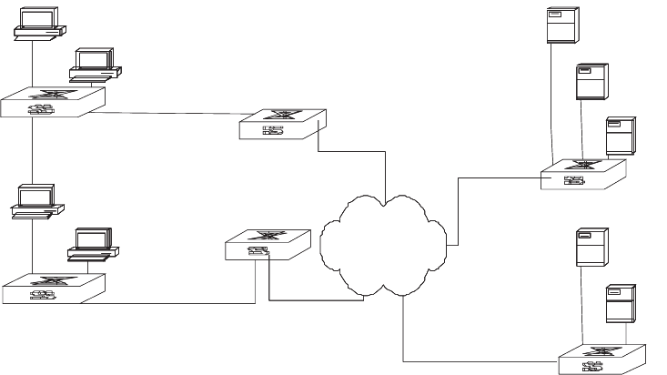
276 CHAPTER 9: AAA AND RADIUS OPERATION
Figure 3 Networking with Switch 8800 Applying RADIUS Authentication
Configuring the AAA and RADIUS Protocols is described in the following sections:
■Configuring AAA
■Configuring the RADIUS Protocol
■Troubleshooting AAA and RADIUS
Configuring AAA AAA configuration includes tasks that are described in the following sections:
■Creating or Deleting an Internet Service Provider (ISP) Domain
■Configuring Relevant Attributes of an ISP Domain
■Creating a Local User
■Setting Attributes of a Local User
■Disconnecting a User by Force
Among the above configuration tasks, creating an ISP domain is required,
otherwise the supplicant attributes cannot be distinguished. The other tasks are
optional. You can configure them at requirements.
Creating or Deleting an Internet Service Provider (ISP) Domain
An Internet Service Provider (ISP) domain is a group of users who belong to the
same ISP. Taking gw20010608@3com163.net as an example in the
userid@isp-name format, the isp-name (i.e. 3com163.net) following the @ is the
ISP domain name. When the Switch 8800 control user access, as for an ISP user
whose username is in userid@isp-name format, the system will take userid part as
username for identification and take isp-name part as domain name.
The purpose of introducing ISP domain settings is to support the multi-ISP
application environment. In such an environment, one access device might access
users of different ISP. Because the attributes of ISP users, such as username and
password formats, etc., may be different, it is necessary to differentiate them by
setting ISP domain. In the Switch 8800 ISP domain view, you can configure a
PC use1
PC user2
PC user3
PC user4
Switch 7700
Switch 7700
Switch 7700
Switch 7700
Internet
ISP1
ISP2
Authentication
server
Accounting
server1

Configuring the AAA and RADIUS Protocols 277
complete set of exclusive ISP domain attributes on a per-ISP domain basis, which
includes AAA policy (RADIUS server group applied etc.)
For the Switch 8800, each supplicant belongs to an ISP domain. Up to 16 domains
can be configured in the system. If a user has not reported its ISP domain name,
the system will put it into the default domain.
Perform the following configurations in system view.
By default, domain named system has been created in the system. The attributes
of system are all default values.
Configuring Relevant Attributes of an ISP Domain
The relevant attributes of ISP domain include the adopted RADIUS server group,
state, and maximum number of supplicants. Where,
■The adopted RADIUS server group is the one used by all the users in the ISP
domain. The RADIUS server group can be used for RADIUS authentication or
accounting. By default, the default RADIUS server group is used. The command
is used together with the commands of setting RADIUS server and server
cluster. For details, refer to “Configuring the RADIUS Protocol ”.
■Every ISP has active/block states. If an ISP domain is in active state, the users
can request for network service, while in block state, users cannot request any
network service. An ISP is in the block state when it is created.
■Maximum number of supplicants specifies how many supplicants can be
contained in the ISP. By default, for any ISP domain, there is no limit to the
number of supplicants.
■The idle cut function means that if the traffic from a certain connection is lower
than the defined traffic, cut off the connection.
Perform the following configurations in ISP domain view.
By default, after an ISP domain is created, the used RADIUS server group is the
default named system (for relevant parameter configuration, refer to “Configuring
the RADIUS Protocol ”), the state of domain is active, there is no limit to the
amount of supplicants, and the idle-cut is disabled.
Table 13 Create/Delete ISP Domain
Operation Command
Create ISP domain or enter the view of a
specified domain.
domain [isp-name | default {disable |
enable isp-name}]
Remove a specified ISP domain undo domain isp-name
Table 14 Configure Relevant Attributes of ISP Domain
Operation Command
Specify the adopted RADIUS server group radius-scheme radius-scheme-name
Specify the ISP domain state to be used state {active | block}
Set a limit to the amount of supplicants access-limit {disable | enable
max-user-number}
Set the idle idle-cut {disable | enable minute flow}

278 CHAPTER 9: AAA AND RADIUS OPERATION
Creating a Local User
A local user is a group of users set on NAS. The username is the unique identifier
of a user. A supplicant requesting network service may use local authentication
only if its corresponding local user has been added onto NAS.
Perform the following configurations in system view.
By default, there is no local user in the system.
Setting Attributes of a Local User
The attributes of a local user include its password, state, service type and other
settings.
Perform the following configurations in system view.
Auto means that the password display mode will be the one specified by the user
at the time of configuring a password (see the password command in the
following table for reference), and cipher-force means that the password display
mode of all the accessing users must be in cipher text.
Perform the following configurations in local user view.
Tab le 15 Create/Delete a Local User and Relevant Properties
Operation Command
Add local users local-user user-name
Delete all the local users undo local-user all
Delete a local user by specifying its type undo local-user { user-name | all
[service-type {lan-access | ftp | telnet }]}
Tab le 16 Set the Method that a Local User Uses to Set Password
Operation Command
Set the method that a local user uses to set
password
local-user password-display-mode {
cipher-force | auto}
Cancel the method that the local user uses to
set password
undo local-user password-display-mode
Tab le 17 Set/Remove the Attributes Concerned with a Specified User
Operation Command
Set a password for a specified user password {simple | cipher} password
Remove the password set for the specified
user
undo password
Set the state of the specified user state {active | block}
Disable the state of the specified user undo state {active | block}
Set a service type for the specified user service-type { ftp [ ftp-directory directory ] |
lan-access | telnet [level level ] ] | telnet [
level level ] }
Cancel the service type of the specified user undo service-type { telnet [ level ] | ftp
[ftp-directory] | lan-access }

Configuring the AAA and RADIUS Protocols 279
Disconnecting a User by Force
Sometimes it is necessary to disconnect a user or a category of users by force. The
system provides the following command to serve this purpose.
Perform the following configurations in system view.
By default, no online user will be disconnected by force.
Configuring the RADIUS
Protocol
On the Switch 8800, the RADIUS protocol is configured per RADIUS server group
basis. In a real networking environment, a RADIUS server group can be an
independent RADIUS server or a set of primary/secondary RADIUS servers with the
same configuration but two different IP addresses. Attributes of every RADIUS
server group include IP addresses of primary and secondary servers, shared key and
RADIUS server type, etc.
RADIUS protocol configuration only defines some necessary parameters using
information for interaction between NAS and RADIUS Server. To make these
parameters effective, it is necessary to configure, in the view, an ISP domain to use
the RADIUS server group, and specify it to use RADIUS AAA schemes. For more
about the configuration commands, refer to “Configuring AAA ”.
Tasks for configuring RADIUS are described in the following sections:
■Creating/Deleting a RADIUS Server Group
■Setting the IP Address and Port Number of RADIUS Server
■Setting the RADIUS Packet Encryption Key
■Setting the Response Timeout Timer of RADIUS Server
■Setting Retransmission Times of the RADIUS Request Packet
■Enabling the Selection of the RADIUS Accounting Option
■Setting a Real-time Accounting Interval
■Setting Maximum Times of Real-time Accounting Request
■Enabling/Disabling Stop Accounting Request Buffer
Configure the attributes of lan-access users attribute {ip ip-address | mac mac-address |
idle-cut second | access-limit
max-user-number | vlan vlanid | location {
nas-ip ip-address port portnum | port
portnum }*
Remove the attributes defined for the
lan-access users
undo attribute {ip | mac | idle-cut |
access-limit | vlan | location }
Table 18 Disconnect a User by Force
Operation Command
Disconnect a user by force cut connection {all | access-type {dot1x |
gcm} | domain domain-name | interface
portnum | ip ip-address | mac mac-address |
radius-scheme radius-scheme-name | vlan
vlanid | ucibindex ucib-index | user-name
user-name }
Table 17 Set/Remove the Attributes Concerned with a Specified User
Operation Command

280 CHAPTER 9: AAA AND RADIUS OPERATION
■Setting the Maximum Retransmitting Times of the Stop Accounting Request
■Setting the Supported Type of RADIUS Server
■Setting RADIUS Server State
■Setting Username Format Transmitted to RADIUS Server
■Setting the Unit of Data Flow that Transmitted to RADIUS Server
■Configuring a Local RADIUS Server Group
■Displaying and Debugging the AAA and RADIUS Protocols
■Configuring FTP/Telnet User Authentication at Remote RADIUS Server
■Configuring FTP/Telnet User Authentication at the Local RADIUS Server
Among the above tasks, creating RADIUS server group, and setting IP address of
the RADIUS server are required, while other takes are optional and can be
performed per your requirements.
Creating/Deleting a RADIUS Server Group
As mentioned above, RADIUS protocol configurations are performed on the per
RADIUS server group basis. Therefore, before performing other RADIUS protocol
configurations, it is compulsory to create the RADIUS server group and enter its
view to set its IP address.
You can use the following commands to create/delete a RADIUS server group.
Perform the following configurations in system view.
Several ISP domains can use a RADIUS server group at the same time.
By default, the system has a RADIUS server group named system whose attributes
are all default values. The default attribute values are introduced in the following
section.
Setting the IP Address and Port Number of RADIUS Server
After creating a RADIUS server group, you set IP addresses and UDP port numbers
for the RADIUS servers, including primary/second authentication/authorization
servers and accounting servers. You can configure up to 4 groups of IP addresses
and UDP port numbers. However, you have to set one group of IP address’ and
UDP port numbers for each pair of primary/second servers to ensure the normal
AAA operation.
Tab le 19 Create/Delete a RADIUS Server Group
Operation Command
Create a RADIUS server group and enter its
view
radius scheme radius-server-name
Delete a RADIUS server group undo radius scheme radius-server-name

Configuring the AAA and RADIUS Protocols 281
Perform the following configurations in RADIUS server group view.
In real networking environments, the above parameters should be set according to
the specific requirements. For example, you may specify 4 groups of different data
to map 4 RADIUS servers, or specify one of the two servers as primary
authentication/authorization server and second accounting server and the other
one as second authentication/authorization server and primary accounting server.
You may also set 4 groups of exactly the same data so that every server serves as a
primary and second AAA server.
To guarantee the normal interaction between NAS and RADIUS server, you are
supposed to guarantee the normal routes between RADIUS server and NAS before
setting IP address and UDP port of the RADIUS server. Because RADIUS protocol
uses different UDP ports to receive/transmit authentication/authorization and
accounting packets, you should set two different ports accordingly. Suggested by
RFC2138/2139, the authentication/authorization port number is 1812 and the
accounting port number is 1813. However, you may use values other than the
ones suggested. (Especially for some earlier RADIUS Servers,
authentication/authorization port number is often set to 1645 and accounting
port number is 1646.)
The RADIUS service port settings on the Switch 8800 need to be consistent with
the port settings on the RADIUS server. Normally, RADIUS accounting service port
is 1813 and the authentication/authorization service port is 1812.
By default, all the IP addresses of primary/second authentication/authorization and
accounting servers are 0.0.0.0, authentication/authorization service port is 1812
and accounting service UDP port is 1813.
Table 20 Set IP Address and Port Number of RADIUS Server
Operation Command
Set IP address and port number of primary
RADIUS authentication/authorization server.
primary authentication ip-address
[port-number]
Restore IP address and port number of primary
RADIUS authentication/authorization or server
to the default values.
undo primary authentication
Set IP address and port number of primary
RADIUS accounting server.
primary accounting ip-address
[port-number]
Restore IP address and port number of primary
RADIUS accounting server or server to the
default values.
undo primary accounting
Set IP address and port number of secondary
RADIUS authentication/authorization server.
secondary authentication ip-address
[port-number]
Restore IP address and port number of second
RADIUS authentication/authorization or server
to the default values.
undo secondary authentication
Set IP address and port number of second
RADIUS accounting server.
Secondary accounting ip-address
[port-number]
Restore IP address and port number of second
RADIUS accounting server or server to the
default values.
undo secondary accounting

282 CHAPTER 9: AAA AND RADIUS OPERATION
Setting the RADIUS Packet Encryption Key
RADIUS client (switch system) and RADIUS server use MD5 algorithm to encrypt
the exchanged packets. The two ends verify the packet by setting the encryption
key. Only when the keys are identical can both ends accept the packets from each
other and give a response.
Perform the following configurations in RADIUS server group view.
Setting the Response Timeout Timer of RADIUS Server
RADIUS (authentication/authorization or accounting) request packet is transmitted
for a specific period of time. If NAS has not received the response from RADIUS
server, it has to retransmit the request to guarantee RADIUS service for the user.
Perform the following configurations in RADIUS server group view.
By default, timeout timer of RADIUS server is 3 seconds.
Setting Retransmission Times of the RADIUS Request Packet
Since RADIUS protocol uses UDP packets to carry the data, the communication
process is not reliable. If the RADIUS server has not responded to NAS before
timeout, NAS has to retransmit the RADIUS request packet. If it transmits the
packet for more than retry-time, and RADIUS server still has not given any
response, NAS considers the communication with the current RADIUS server
disconnected and will transmit the request packet to other RADIUS servers.
Perform the following configurations in RADIUS server group view.
Tab le 21 Set RADIUS Packet Encryption Key
Operation Command
Set RADIUS authentication/authorization
packet encryption key
key authentication string
Restore the default RADIUS
authentication/authorization packet
encryption key.
undo key authentication
Set RADIUS accounting packet key key accounting string
Restore the default RADIUS accounting packet
key
undo key accounting
Tab le 22 Set Response Timeout Timer of RADIUS Server
Operation Command
Set response timeout timer of RADIUS server timer second
Restore the response timeout timer of RADIUS
server to default value
undo timer
Tab le 23 Set Retransmission Times of RADIUS Request Packet
Operation Command
Set retransmission times of RADIUS request
packet
retry retry-time
Restore the default value of retransmission
times
undo retry

Configuring the AAA and RADIUS Protocols 283
By default, RADIUS request packet will be retransmitted up to three times.
Enabling the Selection of the RADIUS Accounting Option
If no RADIUS server is available or if RADIUS accounting server fails when the
accounting optional is configured, the user can still use the network resource,
otherwise, the user will be disconnected.
Perform the following configurations in RADIUS server group view.
The user configured with accounting optional command in RADIUS scheme
longer sends a real-time accounting update packet or offline accounting packet.
The accounting optional command in a RADIUS server group view is only
effective on the accounting that uses this RADIUS server group.
By default, selection of RADIUS accounting option is disabled.
Setting a Real-time Accounting Interval
To implement this feature, it is necessary to set a real-time accounting interval.
After the attribute is set, NAS will transmit the accounting information of online
users to the RADIUS server regularly.
Perform the following configurations in RADIUS server group view.
The minute variable specifies the real-time accounting interval in minutes. The
value must be a multiple of 3.
The value of minute is related to the performance of NAS and RADIUS server. The
smaller the value is, the higher the performances of NAS and RADIUS have to be.
When there are a large amount of users (more than 1000, inclusive), we suggest a
larger value. The following table recommends the ratio of minute value to the
number of users.
By default, minute is set to 12 minutes.
Table 24 Enable the Selection of the RADIUS Accounting Option
Operation Command
Enable the selection of the RADIUS accounting
option
accounting optional
Disable the selection of the RADIUS
accounting option
undo accounting optional
Table 25 Set a Real-Time Accounting Interval
Operation Command
Set a real-time accounting interval timer realtime-accounting minute
Restore the default value of the interval undo timer realtime-accounting
Table 26 Recommended Ratio of Minute to Number of Users
Number of users Real-time accounting interval (minute)
1 to 99 3
100 to 499 6
500 to 999 12
1000 15
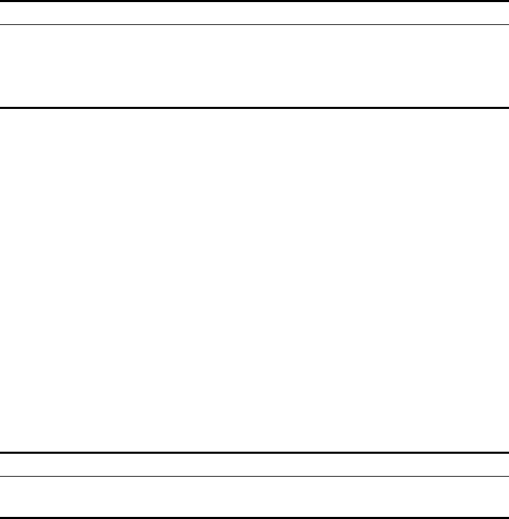
284 CHAPTER 9: AAA AND RADIUS OPERATION
Setting Maximum Times of Real-time Accounting Request
The RADIUS server usually verifies that a user is online with timeout timer. If the
RADIUS server has not received the real-time accounting packet from NAS for a
specified period, it stops accounting. Therefore, it may be necessary to disconnect
the user at the NAS end and on the RADIUS server when some unpredictable
failure exists. The Switch 8800 allows you to configure the maximum number of
retries for real-time accounting requests. NAS disconnects the user if it has not
received a real-time accounting response from the RADIUS server for the specified
number of times.
Perform the following configurations in RADIUS server group view.
The value of retry-times is the ceiling value of T/t, where T is the period of time in
which the RADIUS server connection will timeout, and t is the real-time accounting
interval of NAS.
By default, the value for retry-times is 5.
Enabling/Disabling Stop Accounting Request Buffer
Because the stop accounting request concerns the account balance, and affects
the amount to charge a customer, NAS makes its best effort to send the message
to the RADIUS accounting server. If the message from the Switch 8800 to RADIUS
accounting server has not been responded to, the switch saves it in the local
buffer and retransmits until the server responds or discards the messages. The
following command can be used to enable the storage of the stop accounting
message. If the stop-accounting buffer is enabled, make sure you set the
maximum retransmission time.
Perform the following configurations in RADIUS server group view.
By default, the stop accounting request will be saved in the buffer.
Setting the Maximum Retransmitting Times of the Stop Accounting
Request
Because the stop accounting request concerns account balance, and will affect the
amount to charge a customer, which is very important for both the subscribers
and the ISP, NAS will make its best effort to send the message to the RADIUS
accounting server. If the message from the Switch 8800 to RADIUS accounting
server has not replied, the switch saves it in the local buffer and retransmits it until
Tab le 27 Set Maximum Times of Real-Time Accounting Request Failing to be Responded
Operation Command
Configure the maximum number of retries for
real-time accounting requests.
retry realtime-accounting retry-times
Restore the maximum number of retries for
real-time accounting requests to the default
value.
undo retry realtime-accounting
Tab le 28 Enable/Disable Stopping Accounting Request Buffer
Operation Command
Enable the stop accounting request buffer stop-accounting-buffer enable
Disable the stop accounting request buffer undo stop-accounting-buffer enable

Configuring the AAA and RADIUS Protocols 285
the server responds or discards the messages. Use this command to set the
maximum retransmission times.
Perform the following configurations in RADIUS server group view.
By default, the stop accounting request can be retransmitted for up to 500 times.
Setting the Supported Type of RADIUS Server
The Switch 8800 supports the standard RADIUS protocol and the extended
RADIUS service platforms, such as IP Hotel, and Portal.
Perform the following configurations in RADIUS server group view.
By default, the RADIUS server type is standard.
Setting RADIUS Server State
For the primary and secondary servers, if the primary server is disconnected from
NAS because of a fault, NAS will automatically turn to exchange packets with the
secondary server. However, after the primary server recovers, NAS does not resume
communication with the primary server immediately, instead, it continues
communicating with the secondary server. When the secondary server fails to
communicate, NAS returns to the primary server. The following commands can be
used to set the primary server to be active manually, so that NAS can
communicate with it immediately after troubleshooting.
When the primary and second servers are both active or block, NAS sends the
packets to the primary server only.
Perform the following configurations in RADIUS server group view.
By default, the state of each server in RADIUS server group is active.
Table 29 Set the Maximum Retransmitting Times of Stopping Accounting Request
Operation Command
Set the maximum retransmitting times of stop
accounting request
retry stop-accounting retry-times
Restore the maximum retransmitting times of
stop accounting request to the default value
undo retry stop-accounting
Table 30 Setting the Supported Type of RADIUS Server
Operation Command
Setting the supported type of RADIUS Server server-type {3ComType | iphotel | portal |
standard}
Restore the supported type of RADIUS Server
to the default setting
undo server-type
Table 31 Set RADIUS Server State
Operation Command
Set the state of primary RADIUS server state primary {accounting |
authentication} {block | active}
Set the state of second RADIUS server state secondary{accounting |
authentication} {block | active}

286 CHAPTER 9: AAA AND RADIUS OPERATION
Setting Username Format Transmitted to RADIUS Server
As mentioned before, clients are generally named in userid@isp-name format. The
part following “@” is the ISP domain name. The Switch 8800 will put users into
different ISP domains according to their domain name. However, some earlier
RADIUS servers rejected the username including ISP domain name. In this case,
you have to remove the domain name before sending the username to the
RADIUS server. The following command of switch decides whether the username
to be sent to RADIUS server carries ISP domain name or not.
If a RADIUS server group is configured not to allow usernames including ISP
domain names, the RADIUS server group cannot be simultaneously used in more
than one ISP domain. Otherwise, the RADIUS server will regard two users in
different ISP domains as the same user by mistake, if they have the same
username (excluding their respective domain names.)
By default, the RADIUS server group acknowledges that the username sent to it
includes ISP domain name.
Setting the Unit of Data Flow that Transmitted to RADIUS Server
The following command defines the unit of the data flow sent to RADIUS server.
By default, the default data unit is a byte and the default data packet unit is one
packet.
Configuring a Local RADIUS Server Group
RADIUS service adopts authentication/authorization servers to manage users. Local
authentication/authorization/accounting service is also used in these products and
it is called local RADIUS function.
Perform the following commands in system view to create/delete local RADIUS
server group.
By default, the IP address of local RADIUS server group is 127.0.0.1 and the
password is 3com.
Tab le 32 Set Username Format Transmitted to RADIUS Server
Operation Command
Set username format transmitted to the
RADIUS Server
user-name-format {with-domain |
without-domain}
Tab le 33 Set the Unit of Data Flow Transmitted to RADIUS Server
Operation Command
Set the unit of data flow transmitted to
RADIUS server
data-flow-format data { byte | giga-byte |
kilo-byte | mega-byte } packet { giga-byte |
kilo-byte | mega-byte | one-packet }
Tab le 34 Create/Delete a Local RADIUS Server Group
Operation Command
Create a local RADIUS server group and enter
its view
local-server nas-ip ip-address key password
Delete a local RADIUS server group undo local-server nas-ip ip-address

Configuring the AAA and RADIUS Protocols 287
When using the local RADIUS server function of the Switch 8800, remember that:
■The number of the UDP port used for authentication is 1645 and the number
for accounting is 1646.
■The password configured by local-server command must be the same as that of
the RADIUS authentication/authorization packet configured by the command
key authentication in the Radius server group view
Displaying and Debugging the AAA and RADIUS Protocols
After you configure RADIUS, execute the display command in all views to display
the operation of the AAA and RADIUS configuration, and to verify the effect of
the configuration. Execute the reset command in user view to reset AAA and
RADIUS configuration. Execute the debugging command in user view to debug
AAA and RADIUS.
Example: AAA and
RADIUS Protocol
Configuration
AAA/RADIUS protocol configuration commands are generally used together with
802.1x configuration commands. Refer to the typical configuration examples
provided in “Configuring 802.1x” on page 267.
Configuring FTP/Telnet User Authentication at Remote RADIUS Server
Configuring Telnet user authentication at the remote server is similar to
configuring FTP users. The following description is based on Telnet users.
Table 35 Display and Debug AAA and RADIUS Protocol
Operation Command
Display the configuration information of the
specified or all the ISP domains.
display domain [isp-name]
Display related information of user’s
connection
display connection {access-type {dot1x |
gcm} | domain isp-name | interface portnum
| ip ip-address | mac mac-address |
radius-scheme radius-scheme-name | vlan
vlanid | ucibindex ucib-index | user-name
user-name}
Display related information of the local user display local-user [domain isp-name |
idle-cut {disable | enable} | service-type
{telnet | ftp | lan-access } | state {active |
block} | user-name user-name | vlan vlan-id]
Display information of local RADIUS server
group
display local-server statistics
Display the configuration information of all
the RADIUS server groups or a specified one
display radius [radius-server-name]
Display the statistics information of RADIUS
packets
display radius statistics
Reset the statistics of the Radius server reset radius statistics
Display the stopping accounting requests
saved in buffer without response (from system
view)
display stop-accounting-buffer
{radius-scheme radius-scheme-name |
session-id session-id | time-range start-time
stop-time | user-name user-name}
Delete the stopping accounting requests
saved in buffer without response (from system
view)
reset stop-accounting-buffer
{radius-scheme radius-scheme-name |
session-id session-id | time-range start-time
stop-time | user-name user-name}
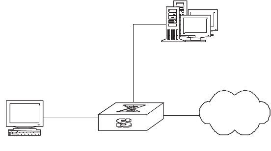
288 CHAPTER 9: AAA AND RADIUS OPERATION
In the environment illustrated in the following figure, it is required to achieve
through proper configuration that the RADIUS server authenticates the Telnet
users to be registered.
One RADIUS server (as authentication server) is connected to the switch and the
server IP address is 10.110.91.146. The password for exchanging messages
between the switch and the authentication server is "expert". The switch cuts off
domain name from username and sends the left part to the RADIUS server.
Figure 4 Configuring Remote RADIUS Authentication for Telnet Users
1Add a Telnet user.
For details about configuring FTP and Telnet users, see “Configuring the User
Interface” on page 11.
2Configure the remote authentication mode for the Telnet user, in this example, the
scheme mode.
[SW8800-ui-vty0-4]authentication-mode scheme
3Configure the domain.
[SW8800]domain cams
[SW8800-isp-cams]quit
4Configure RADIUS scheme.
[SW8800]radius scheme cams
[SW8800-radius-cams]primary authentication 10.110.91.146 1812
[SW8800-radius-cams]key authentication expert
[SW8800-radius-cams]server-type 3com
[SW8800-radius-cams]user-name-format without-domain
5Configure the association between domain and RADIUS.
[SW8800-radius-cams]quit
[SW8800]domain cams
[SW8800-isp-cams]radius-scheme cams
Configuring FTP/Telnet User Authentication at the Local RADIUS Server
Local RADIUS authentication of Telnet/FTP users is similar to remote RADIUS
authentication. But you should modify the server IP address to 127.0.0.1,
authentication password to 3Com, the UDP port number of the authentication
server to 1645.
Authentication Servers
(IP address: 10.110.91.164)
Internet
Switch
Telnet user
Configuring the AAA and RADIUS Protocols 289
For details about local RADIUS authentication of Telnet/FTP users, see
“Configuring a Local RADIUS Server Group”on page 286.
Troubleshooting AAA
and RADIUS
The RADIUS protocol of TCP/IP protocol suite is located on the application layer. It
basically specifies how to exchange user information between NAS and RADIUS
server of ISP. So it is likely to be invalid.
Tasks for Troubleshooting AAA and Radius are described in the following sections:
■User authentication/authorization always fails
■RADIUS packet cannot be transmitted to RADIUS server.
■After being authenticated and authorized, the user cannot send charging bill
to the RADIUS server.
User authentication/authorization always fails
1The username may not be in the userid@isp-name format or NAS has not been
configured with a default ISP domain. Please use the username in proper format
and configure the default ISP domain on NAS.
2The user may not have been configured in the RADIUS server database. Check the
database and make sure that the configuration information of the user does exist
in the database.
3The user may have input a wrong password. Make sure that the supplicant inputs
the correct password.
4The encryption keys of RADIUS server and NAS may be different. Check carefully
and make sure that they are identical.
5There might be some communication fault between NAS and RADIUS server,
which can be discovered through pinging RADIUS from NAS. Ensure the normal
communication between NAS and RADIUS.
RADIUS packet cannot be transmitted to RADIUS server.
1The communication lines (on physical layer or link layer) connecting NAS and
RADIUS server may not work well.
2The IP address of the corresponding RADIUS server may not have been set on NAS.
Set a proper IP address for RADIUS server.
3UDP ports of authentication/authorization and accounting services may not be set
properly. Make sure they are consistent with the ports provided by RADIUS server.
After being authenticated and authorized, the user cannot send charging
bill to the RADIUS server.
1The accounting port number may be set improperly. Set a proper number.
2The accounting service and authentication/authorization service are provided on
different servers, but NAS requires the services to be provided on one server (by
specifying the same IP address). Make sure the settings of servers are consistent
with the actual conditions.
290 CHAPTER 9: AAA AND RADIUS OPERATION
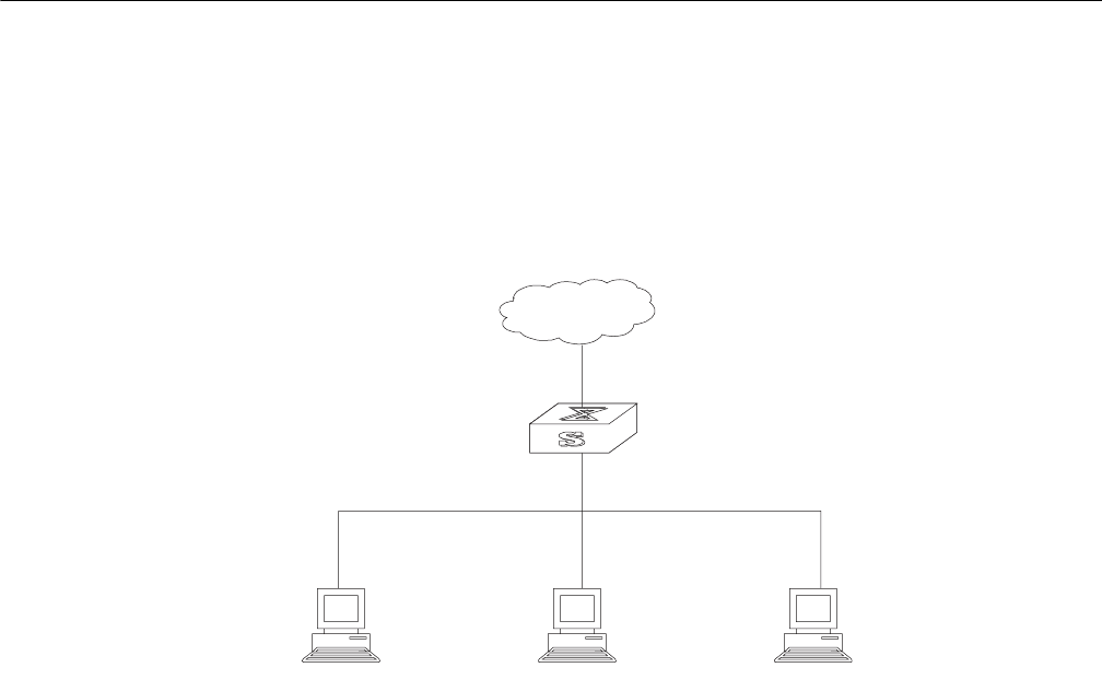
10 RELIABILITY
This chapter covers the following topics:
■VRRP Overview
■Configuring VRRP
VRRP Overview Virtual Router Redundancy Protocol (VRRP) is a fault-tolerant protocol. In general,
a default route, for example, 10.100.10.1 in Figure 1, is configured for every host
on a network, so that packets destined for another network segment go through
the default route to Layer 3 Switch1, implementing communication between the
host and the external network. If Switch1 is down, all the hosts on this segment
have Switch1 as the next-hop for the default route and are disconnected from the
external network.
Figure 1 LAN Networking
VRRP, which is designed for LANs with multicast and broadcast capabilities (such
as Ethernet) settles this problem. Figure 2 illustrates the implementation principal
of VRRP. VRRP combines a group of LAN switches, including a master and several
backups, into a virtual router, or backup group.
Internet
Switch
10.100.10.1 Ethernet
10.100.10.7 10.100.10.8 10.100.10.9
Host 1 Host 2 Host 3
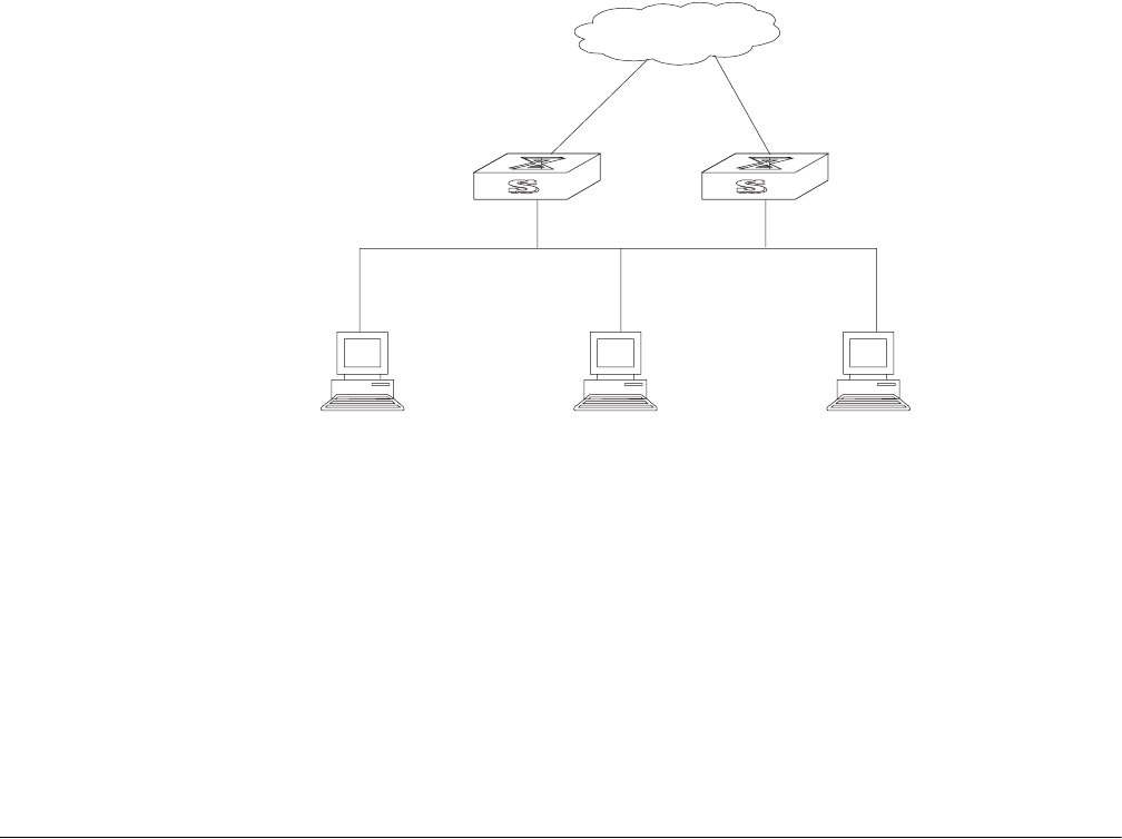
292 CHAPTER 10: RELIABILITY
Figure 2 Virtual Router
This virtual router has its own IP address: 10.100.10.1, which can be the actual
interface address of a switch within the virtual router. The switches within the
virtual router have their own IP addresses, such as 10.100.10.2 for the Master
switch and 10.100.10.3 for the BACKUP switch. The hosts on the LAN use the IP
address of this virtual router 10.100.10.1, but not the specific IP addresses
10.100.10.2 of the master switch and 10.100.10.3 of the backup switch. The
default routes for the hosts on this LAN are configured using the IP address of this
virtual router 10.100.10.1 as their gateway. Therefore, hosts within the network
communicate with the external network through this virtual router. If a master
switch in the virtual router group breaks down, the backup switch functions as the
new master switch. This avoids interrupting communication between the hosts
and external networks.
Configuring VRRP VRRP configuration tasks are described in the following sections:
■Enable Pinging the Virtual IP Address
■Setting Correspondence Between Virtual IP and MAC Addresses
■Adding and Deleting a Virtual IP Address
■Configuring the Priority of Switches
■Configuring Preemption and Delay for a Switch
■Configuring Authentication Type and Authentication Key
■Configuring the VRRP Timer
■Configuring a Switch to Track an Interface
Enable Pinging the
Virtual IP Address
This operation enables or disables ping response for the virtual IP address of the
backup group. The standard VRRP protocol does not support ping response.
Network
Actual IP address 10.100.10.2
Master
Actual IP address 10.100.10.3
Backup
Virtual IP address 10.100.10.1Virtual IP address 10.100.10.1 Ethernet
Host 1 Host 2 Host 3
10.100.10.7 10.100.10.8 10.100.10.9

Configuring VRRP 293
Perform the following commands in system view.
By default, ping response for the virtual IP address is disabled.
Setting Correspondence
Between Virtual IP and
MAC Addresses
This operation sets the virtual IP address to correspond to either the real or the
virtual MAC address. In the standard VRRP protocol, the virtual IP address of the
backup group corresponds to the virtual MAC address, and guarantees correct
data forwarding in the sub-net.
The Switch 8800 switches support matching the virtual IP address with either the
real MAC address or the virtual MAC address of the routing interface.
The following command can be used to establish a relationship between the IP
address and the MAC address.
Perform the following configuration in system view.
By default, the virtual IP address of the backup group corresponds to the virtual
MAC address.
You should set correspondence between the virtual IP address of the backup
group and the MAC address before configuring the backup group; other wise, you
cannot configure the correspondence.
Adding and Deleting a
Virtual IP Address
The virtual-router-ID covers the range from 1 to 255. The virtual-address can be an
unused address in the network segment where the virtual router resides, or the IP
address of an interface in the virtual router. If the IP address is on the switch, the
switch is called an IP address owner. When adding the first IP address to a virtual
router, the system creates a new virtual router instance. When adding new
addresses to this backup group thereafter, the system adds it directly to the virtual
IP address list.
After the last virtual IP address is removed from the virtual router, the whole virtual
router is removed.
The following command is used for assigning an IP address from the local segment
to a virtual router, or removing an assigned virtual IP address of a virtual router
from the virtual address list.
Table 1 Enable/Disable the Ping Function
Operation Command
Enable pinging of the virtual IP address vrrp ping-enable
Disable pinging of the virtual IP address undo vrrp ping-enable
Table 2 Set the Correspondence Between Virtual IP and MAC Addresses
Operation Command
Set correspondence between the virtual IP
address and the MAC address
vrrp method { real-mac | virtual-mac }
Set the correspondence to the default value undo vrrp method

294 CHAPTER 10: RELIABILITY
Perform the following configuration in VLAN interface view.
Configuring the Priority
of Switches
The status of each switch in the virtual router group is determined by its priority in
VRRP. The switch with the highest priority becomes the master.
The priority ranges from 0 to 255 (the greater the number, the higher the priority.
However only values from 1 to 254 can be used. Priority 0 is reserved for special
use and 255 is reserved for the IP address owner.
Perform the following configuration in VLAN interface view.
By default, the priority is 100.
The priority for an IP address owner is always 255, which cannot be changed.
Configuring Preemption
and Delay for a Switch
When a switch in the virtual router functions as a master switch, other switches,
even if they are configured with a higher priority later, cannot become the master
switch unless they are configured to work in preemption mode. The switch in
preemption mode can become the master switch when it finds that its own
priority is higher than the priority of the current master switch. If this happens, the
former master switch becomes the backup switch.
In addition to preemption settings, a delay can also be set. A backup switch waits
for a period of time before becoming a master. In an unstable network, if the
backup switch has not received packets from the master switch periodically, it
becomes the master switch. However, the failure of the backup switch to receive
packets may be due to network congestion instead of the malfunction of the
master switch. In this case, the backup switch receives the packets after a while.
The delay settings can thereby avoid a frequent change of status.
Perform the following configuration in VLAN interface view.
Tab le 3 Add/Delete a Virtual IP Address
Operation Command
Add a virtual IP address. vrrp vrid virtual-router-ID virtual-ip
virtual-address
Delete a virtual IP address. undo vrrp vrid virtual-router-ID [ virtual-ip
virtual-address ]
Tab le 4 Configure the Priority of Switches in the Virtual Router
Operation Command
Configure the priority of switches in the virtual
router.
vrrp vrid virtual-router-ID priority priority
Clear the priority of switches in the virtual
router.
undo vrrp vrid virtual-router-ID priority
Tab le 5 Configure Preemption and Delay for a Switch
Operation Command
Enable the preemption mode and configure a
period of delay.
vrrp vrid virtual-router-ID preempt-mode [
timer delay delay-value ]
Disable the preemption mode. undo vrrp vrid virtual-router-ID
preempt-mode

Configuring VRRP 295
The delay ranges from 0 to 255, measured in seconds. The default mode is
preemption with a delay of 0 second.
Configuring
Authentication Type and
Authentication Key
To prevent unauthorized routes from joining the virtual router, a key can be
configured that is used in one of the following VRRP authentication types:
■Simple character authentication — The authentication type is set to simple.
The switch adds the authentication key to the VRRP packets before
transmitting it. The receiver compares the authentication key of the packet to
the locally configured authentication key. If they are the same, the packet is
accepted as a true and legal. If the keys are not the same the packet is
considered illegal and is discarded. A simple authentication key should not
exceed 8 characters.
■MD5 authentication — The authentication type is set to md5. The switch uses
the authentication type and MD5 algorithm, provided by the authentication,
header to authenticate VRRP packets. An md5 authentication key should not
exceed 16 packets that fail to pass the authentication test. If 16 fail they are
discarded and a trap packet is sent to the network management system.
Perform the following configuration in VLAN interface view.
The same authentication type and authentication key should be configured for all
vlan interfaces that belong to the virtual router.
Configuring the VRRP
Timer
The Master switch advertises its normal operation state to the switches within the
VRRP virtual router by sending them VRRP packets regularly, at the specified
advertised interval. If the backup switch does not receive a VRRP packet from the
master after a period of time (specified by master-down-interval), the master is
assumed to have failed and the backup switch takes the role of master.
You can use the following command to set a timer and adjust the interval,
adver-interval at which the master transmits VRRP packets. The duration of the
backup switch’s master-down-interval is three times the duration of the
adver-interval. Excessive network traffic or the differences between different
switch timers results in master-down-interval timing out and state changing
abnormally. Such problems can be solved through prolonging the adver-interval
and setting delay time. The duration of adver-interval is measured in seconds.
Perform the following configuration in VLAN interface view.
Table 6 Configure Authentication Type and Authentication Key
Operation Command
Configure the authentication type and
authentication key.
vrrp authentication-mode type [ key ]
Clear the authentication type and
authentication key.
undo vrrp authentication-mode
Table 7 Configure VRRP Timer
Operation Command
Configure VRRP timer vrrp vrid virtual-router-ID timer advertise
adver-interval

296 CHAPTER 10: RELIABILITY
By default, adver-interval is 1.
Configuring a Switch to
Track an Interface
The VRRP track interface function expands the backup function by including other
switch interfaces of participating routers. Backup is provided not only to the
interface where the virtual router resides, but also to other switch interfaces of
participating routers. By implementing the following command you can track
interfaces. If the interface that is being tracked fails, the priority of the switch,
including the interface, decreases automatically by the value specified by
value-reduced. The reduced priority of the switch results in comparatively higher
priorities of other switches within the virtual router, one of which becomes the
master switch.
Perform the following configuration in VLAN interface view.
By default, value-reduced is set at 10.
When the switch is an IP address owner, its interfaces cannot be tracked.
Displaying and
Debugging VRRP
After you configure a virtual router, execute the display command in all views to
display the VRRP configuration, and to verify the effect of the VRRP configuration.
You can enable VRRP debugging to display how it runs. You can set the argument
option to packet or state to debug the VRRP packet or VRRP state.
By default, the switch disables debugging.
Example: VRRP Single
Virtual Router
Host A uses the VRRP virtual router which combines switch A and switch B as its
default gateway to visit host B on the Internet.
Clear VRRP timer undo vrrp vrid virtual-router-ID timer
advertise
Table 7 Configure VRRP Timer
Operation Command
Tab le 8 Configure Switch to Track a Specified Interface
Operation Command
Configure to track a specified interface vrrp vrid virtual-router-ID track
vlan-interface interface-num [ reduced
value-reduced ]
Stop tracking the specified interface undo vrrp vrid virtual-router-ID track [
vlan-interface interface-num ]
Tab le 9 Display and Debug VRRP
Operation Command
Display VRRP state information. display vrrp [ interface vlan-interface
interface-num ] [ virtual-router-ID ]
Enable VRRP debugging. debugging vrrp { state | packet }
Clear VRRP statistics reset vrrp statistics [ vlan-interface
interface-num [ virtual-router-ID ] ]
Disable VRRP debugging. undo debugging vrrp { state | packet }
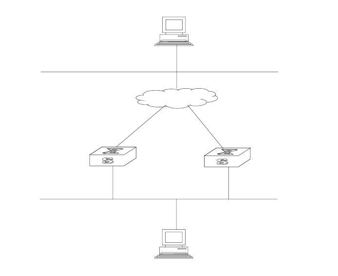
Configuring VRRP 297
VRRP virtual router information includes virtual router ID1, virtual IP address
202.38.160.111, switch A as the Master and switch B as the backup allowed
preemption.
Figure 3 VRRP Configuration
Configure switch A:
[SW8800_A-vlan-interface2]vrrp vrid 1 virtual-ip 202.38.160.111
[SW8800_A-vlan-interface2]vrrp vrid 1 priority 110
Configure switch B:
[SW8800_B-vlan-interface2]vrrp vrid 1 virtual-ip 202.38.160.111
The virtual router can be used after all routers in the group are configured. The
host A default gateway should be configured as 202.38.160.111.
Under normal conditions, switch A functions as the gateway, but when switch A is
turned off or is malfunctioning, switch B functions as the gateway instead.
Example: VRRP Tracking
Interface
Even when switch A is still functioning, it may want Switch B to function as a
gateway if a critical interface connected with it does not function properly. This
can be implemented by configuring a tracking interface. The virtual router ID is set
to 1 with additional configurations of an authorization key and timer.
Configure switch A
1Create a virtual router.
[SW8800_A-vlan-interface2]vrrp vrid 1 virtual-ip 202.38.160.111
2Set the priority for the virtual router.
10.2.3.1
Host B
Internet
Switch B
VLAN-interface3: 10.100.10.2
Switch A
VLAN-interface2: 202.38.160.2
Virtual IP address: 202.38.160.111
202.36.160.3
VLAN-interface2: 202.38.160.1
Host A

298 CHAPTER 10: RELIABILITY
[SW8800_A-vlan-interface2]vrrp vrid 1 priority 110
3Set the authentication key for the virtual router.
[SW8800_A-vlan-interface2]vrrp authentication-mode md5 lanswitch
4Set Master to send VRRP packets every 5 seconds.
[SW8800_A-vlan-interface2]vrrp vrid 1 timer advertise 5
5Track an interface.
[SW8800_A-vlan-interface2]vrrp vrid 1 track vlan-interface 3 reduced
30
Configure switch B
1Create a virtual router.
[SW8800_B-vlan-interface2]vrrp vrid 1 virtual-ip 202.38.160.111
2Set the authentication key for the virtual router.
[SW8800_B-vlan-interface2]vrrp authentication-mode md5 lanswitch
3Set Master to send VRRP packets every 5 seconds.
[SW8800_B-vlan-interface2]vrrp vrid 1 timer advertise 5
Under normal conditions, switch A functions as the gateway. When the interface
vlan-interface 3 of switch A is down, its priority is reduced by 30, so run priority is
80. This run priority value is lower than the run priority value of switch B so switch
B preempts the master for gateway services.
When vlan-interface3, the switch A interface, recovers, this switch resumes its
gateway function as master.
Example: Multiple
Virtual Routers
A Switch can function as the backup switch for many virtual routers.
Such a multi-backup configuration can implement load balancing. For example,
switch A, as master switch of group 1, can share the responsibility of the backup
switch for virtual router 2, and switch B performs the same functions for group 2
and virtual router 1. Some hosts employ virtual router 1 as the gateway, while
others employ virtual router 2 as the gateway. In this way, both load balancing and
mutual backup are possible.
Load balancing is not supported in virtual-mac mode.
Configure switch A:
1Create virtual router 1.
[SW8800_A-vlan-interface2]vrrp vrid 1 virtual-ip 202.38.160.111
2Set the priority for the virtual router.
[SW8800_A-vlan-interface2]vrrp vrid 1 priority 150
3Create virtual router 2.
[SW8800_A-vlan-interface2]vrrp vrid 2 virtual-ip 202.38.160.112
Configure switch B:
1Create virtual router 1.
[SW8800_B-vlan-interface2]vrrp vrid 1 virtual-ip 202.38.160.111
Configuring VRRP 299
2Create virtual router 2.
[SW8800_B-vlan-interface2]vrrp vrid 2 virtual-ip 202.38.160.112
3Set the priority for the virtual router.
[SW8800_B-vlan-interface2]vrrp vrid 2 priority 110
Troubleshooting VRRP The configuration of VRRP is simple so almost all troubleshooting can be done by
viewing the configuration and debugging information. Here are some possible
failures you might experience and the corresponding troubleshooting methods.
Tasks for Troubleshooting VRRP are described in the following sections:
■Frequent Prompts of Configuration Errors on the Console
■More than One Master Exists Within the Same Virtual Router
■Frequent Switchover of VRRP State
Frequent Prompts of Configuration Errors on the Console
This indicates that an incorrect VRRP packet has been received. It may be because
of the inconsistent configuration of another switch within the virtual router, or the
attempt of some devices to send out illegal VRRP packets.
The first possible fault can be solved by modifying the configuration. Because the
second possibility is caused by the malicious attempt of some devices, you should
resort to non-technical measures.
More than One Master Exists Within the Same Virtual Router
One possible reason for this situation is the short-time coexistence of many master
switches; which is normal and needs no manual intervention.
Another possible reason is the coexistence of many master switches over a long
period of time, because several masters cannot receive VRRP packets from each
other, or because they have received illegal packets.
To solve this problem, ping the Master switches. If pinging fails, there are other
problems. If the masters can be pinged, it indicates that the problems are caused
by an inconsistent configuration. For the configuration of the same VRRP virtual
router, the number of virtual IP addresses, each virtual IP address, timer duration,
and authentication type, must be consistent.
Frequent Switchover of VRRP State
This problem occurs when the virtual router timer duration is set too short.
Increase the duration of the timer or configure a preemption delay.
300 CHAPTER 10: RELIABILITY

11 SYSTEM MANAGEMENT
This chapter covers the following topics:
■File System
■Managing the MAC Address Table
■Managing Devices
■Maintaining and Debugging the System
■SNMP
■RMON
■NTP
File System The Switch 8800 provides a file system module for efficient management with
storage devices such as flash memory. The file system offers file access and
directory management, including creating the file system; creating, deleting,
modifying, and renaming a file or a directory; and opening files.
By default, the file system requires that the user confirm before executing
commands. This prevents unwanted data loss.
Managing the file system is described in the following sections:
■Using a Directory
■Managing Files
■Formatting Storage Devices
■Setting the Prompt Mode of the File System
■Configuring File Management
■FTP
■TFTP
Using a Directory You can use the file system to create or delete a directory, display the current
working directory, and display the information about the files or directories under
a specified directory. Use the commands in Tab l e 1 to perform directory
operations.
Perform the following operations in user view.
Table 1 Directory Operation
Operation Command
Create a directory mkdir directory

302 CHAPTER 11: SYSTEM MANAGEMENT
Managing Files You can use the file system to delete, undelete, or permanently delete a file. It can
also be used to display file contents; rename, copy, and move a file; and display
the information about a specified file. Use the commands in Table 2 to perform file
operations.
Perform the following operations in user view.
Formatting Storage
Devices
The file system can be used to format the flash memory on the Switch 8800 fabric
module.
Perform the following operation in user view.
Setting the Prompt
Mode of the File System
Use the command in Table 4 to confirm prompts for file system commands.
Perform the following operation in system view.
Delete a directory rmdir directory
Display the current working directory pwd
Display the information about directories or
files
dir [ / all ] [ file-url ]
Change the current directory cd directory
Table 1 Directory Operation
Operation Command
Tab le 2 File Operation
Operation Command
Delete a file from the file system and move it
to the recycle bin
delete file-url
Restore a file from the recycle bin undelete file-url
Delete a file from the recycle bin permanently reset recycle-bin file-url
View contents of a file more file-url
Rename a file rename fileurl-source fileurl-dest
Copy a file copy fileurl-source fileurl-dest
Move a file move fileurl-source fileurl-dest
Display the information about directories or
files
dir [ / all ] [ file-url ]
Execute a batch file (system view) execute filename
Tab le 3 Formatting Storage Devices
Operation Command
Format the storage device format filesystem
Tab le 4 File System Operation
Operation Command
Set the file system prompt mode. file prompt { alert | quiet }
File System 303
Example: File System
Operation
1Format the flash.
<SW8800>format flash:
All sectors will be erased, proceed? [confirm] y
Format flash: completed
2Display the working directory in the flash.
<SW8800>cd flash:/
<SW8800>pwd
flash:/
3Create a directory named test.
<SW8800>mkdir test
4Display the flash directory information after creating the test directory.
<SW8800>dir
Directory of flash:/
0 -rw- 6703685 Nov 12 2004 16:01:53 88003-00.app
1 drw- - Nov 12 2004 16:04:26 hafile
2 -rw- 4 Dec 03 2004 04:46:36 snmpboots
3 -rw- 1823 Dec 03 2004 04:45:02 sw8800.cfg
4 -rw- 6326532 Dec 03 2004 04:44:04 88003-00ec06.app
15621 KB total (2836 KB free)
Configuring File
Management
The configuration file includes commands based on command views. The
commands are sorted in one section and sections are separated with a blank line
or a comment line (A comment line begins with a pound sign “# ”). Default
constants are not saved.
Generally, the sections in the file are arranged in the following order: system
configuration, ethernet port configuration, vlan interface configuration, routing
protocol configuration, and so on.
Management of the configuration files includes tasks described in the following
sections:
■Displaying the Current and Saved Configuration of the Switch
■Saving the Current Configuration
■Erasing the Configuration Files from Flash Memory
Displaying the Current and Saved Configuration of the Switch
After being powered on, the system reads the configuration file from flash
memory. The default configuration file is sw8800.cfg. If there is no configuration
file in flash, the system begins the initialization with the default parameters. You
can use the commands in Tab le 5 to display the current and saved configuration of
the switch.

304 CHAPTER 11: SYSTEM MANAGEMENT
Perform the following configuration in all views.
The configuration files are displayed in their corresponding saving formats.
Saving the Current Configuration
Use the save command to retain the current-configuration in the flash memory.
The configurations are saved when the system is powered on for the next time.
Perform the following configuration in user view.
Erasing the Configuration Files from Flash Memory
The reset saved-configuration command can be used to erase the configuration
files from flash memory. The system will use the default configuration parameters
for initialization when the switch is powered on the next time.
Perform the following configuration in user view.
You can erase the configuration files from flash memory in the following cases:
■If the software does not match the configuration files after the software is
upgraded.
■If the configuration files in flash are damaged, for example, if the wrong
configuration file has been downloaded.)
FTP FTP is a common way to transmit files on the Internet and IP network. FTP is a
TCP/IP protocol on the application layer and is used for transmitting files between
a remote server and a local host.
The Ethernet switch provides the following FTP services:
■FTP server — You can run the FTP client program to log in to the server and
access the files on it.
■FTP client — After connecting to the server by running the terminal emulator or
Telnet on a PC, you can access the files on it, using the FTP command.
Tab le 5 Display the Configurations of the Switch
Operation Command
Display the saved configuration of the
Ethernet switch
display saved-configuration
Display the current configuration of the
Ethernet switch
display current-configuration [ controller |
interface interface-type [ interface-number ] |
configuration [ configuration ] [ | { begin |
exclude | include } regular-expression ]
Tab le 6 Save the Current-Configuration
Operation Command
Save the current-configuration save
Tab le 7 Erase the Configuration Files from Flash Memory
Operation Command
Erase the configuration files from the Flash
Memory
reset saved-configuration

File System 305
FTP Server configuration includes tasks described in the following sections:
■Enabling and Disabling the FTP Server
■Configuring the FTP Server Authentication and Authorization
■Configuring FTP Server Parameters
■Displaying and Debugging the FTP Server
Enabling and Disabling the FTP Server
You can use the following commands to enable or disable the FTP server. Perform
the following configuration in system view.
The FTP server supports multiple user access. A remote FTP client sends a request
to the FTP server. Then, the FTP server carries out the corresponding operation and
returns the result to the client.
By default, the FTP server is disabled.
Configuring the FTP Server Authentication and Authorization
You can use the following commands to configure FTP server authentication and
authorization. The authorization information of the FTP server includes the top
working directory provided for FTP clients.
Perform the following configuration in system view.
Only clients who have passed the authentication and authorization successfully
can access the FTP server.
Configuring FTP Server Parameters
You can use the following commands to configure the connection timeout of the
FTP server. If the FTP server does not receive a service request from the FTP client
Table 8 Enable/Disable FTP Server
Operation Command
Enable the FTP server ftp server enable
Disable the FTP server undo ftp server
Table 9 Configure the FTP Server Authentication and Authorization
Operation Command
Create new local user and enter local user
view (system view)
local-user username
Delete local user (system view) undo local-user [ username | all [
service-type ftp ]]
Configure password for local user (local user
view)
password [ cipher | simple ] password
Configure service type for local user (local user
view)
service-type ftp ftp-directory directory
Cancel password for local user (local user
view)
undo password
Cancel service type for local user (local user
view)
undo service-type ftp [ftp-directory]

306 CHAPTER 11: SYSTEM MANAGEMENT
for a period of time, it will cut the connection to it, thereby avoiding illegal access
by unauthorized users.
Perform the following configuration in system view.
By default, the FTP server connection timeout is 30 minutes.
Displaying and Debugging the FTP Server
Execute the display command in all views to display the FTP Server configuration,
and to verify the effect of the configuration.
The display ftp-server command can be used for displaying configuration
information about the current FTP server, including, the maximum amount of users
supported by FTP server and the FTP connection timeout. The display ftp-user
command can be used for displaying the detail information about connected FTP
users.
TFTP Trivial File Transfer Protocol (TFTP) is a simple protocol for file transmission that has
no complicated interactive access interface or authentication control, and
therefore it can be used when there is no complicated interaction between the
clients and server.
TFTP transmission originates with the client. To download a file, the client sends a
request to the TFTP server and receives the data, then sends an acknowledgement
to it. To upload a file, the client sends a request to the TFTP server and transmits
data to it, then receives the acknowledgement from it.
TFTP configuration tasks include:
■Configuring the File Transmission Mode
■Downloading Files with TFTP
■Downloading Files with TFTP
Configuring the File Transmission Mode
TFTP transmits files in two modes; binary mode for program files and ASCII mode
for text files. Use the following commands to configure the file transmission
mode.
Tab le 10 Configure FTP Server Connection Timeout
Operation Command
Configure FTP server connection timeouts ftp timeout minute
Restoring the default FTP server connection
timeouts
undo ftp timeout
Tab le 11 Display and Debug the FTP Server
Operation Command
Display FTP server display ftp-server
Display the connected FTP users. display ftp-user

Managing the MAC Address Table 307
Perform the following configuration in system view.
By default, TFTP transmits files in binary mode.
Downloading Files with TFTP
To download a file, the client sends a request to the TFTP server and receives data
from it, then sends acknowledgement to it. Use the following commands to
download files with TFTP.
Perform the following configuration in system view.
Uploading Files with TFTP
To upload a file, the client sends a request to the TFTP server and transmits data to
it, then receives the acknowledgement from it. Use the following commands to
upload files.
Perform the following configuration in system view.
Managing the MAC
Address Table
The Switch 8800 maintains a MAC address table for fast forwarding of packets. A
table entry includes the MAC address of a device and the port ID of the switch
connected to it. The switch learns dynamic entries when it receives a data frame
from a port (assumed as port A). The switch analyzes the source MAC address and
considers that the packets destined for the source MAC address can be forwarded
through port A. If the MAC address table contains the MAC_SOURCE, the switch
updates the corresponding entry, otherwise, it adds the new MAC address (and
the corresponding forwarding port) as a new entry to the table.
The system forwards the packets whose destination addresses can be found in the
MAC address table. The network device responds after receiving a broadcast
packet and the response contains the MAC address of the device, which the
switch learns and adds in the MAC address table. After this, subsequent packets
destined for the same MAC address can be forwarded directly.
Table 12 Configuring the File Transmission Mode
Operation Command
Configure the file transmission mode tftp { ascii | binary }
Table 13 Downloading Files with TFTP
Operation Command
Download files with TFTP tftp tftp-server get source-file [ dest-file ]
Table 14 Uploading Files with TFTP
Operation Command
Upload files with TFTP tftp tftp-server put source-file [ dest-file ]
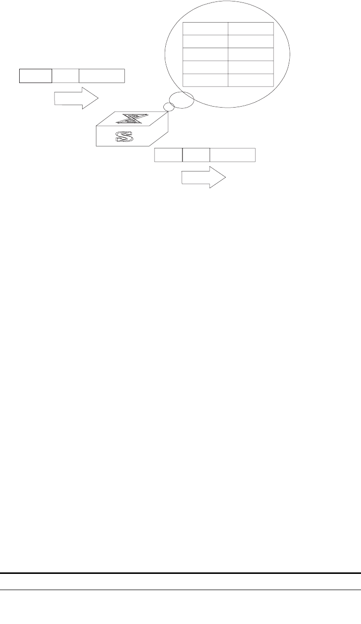
308 CHAPTER 11: SYSTEM MANAGEMENT
Figure 1 The Switch 8800 Forwards Packets According to the MAC Address Table
The Switch 8800 also provides the function of MAC address aging. If the switch
does not receive a packet from a MAC address for a set period of time, it will
delete the related entry from the MAC address table.
You can add or modify MAC address entries manually according to the actual
networking environment. The entries can be static or dynamic. The default aging
time is five minutes.
Configuring the MAC
Address Table
MAC address table management includes:
■Setting MAC Address Table Entries
■Disabling or Enabling Global MAC Address Learning
■Disabling or Enabling MAC Address Learning on a Port
■Setting MAC Address Aging Time
■Setting the Maximum MAC Addresses an Ethernet Port can Learn
■Displaying and Debugging the MAC Address Table
Setting MAC Address Table Entries
You can manually add, modify, or delete entries in a MAC address table according
to actual needs. you can also delete all (unicast) MAC address table entries related
to a specified port or delete a specified type of entries, such as dynamic or static
entries.
Use the following commands to add, modify, or delete the entries in MAC address
table.
Perform the following configuration in system view.
MACD MACA ....
Port 1
MAC Address Port
MACA
MACB
MACC
MACD
1
1
2
2
MACD MACA
Port 2
....
Tab le 15 Setting MAC Address Table Entries
Operation Command
Add or modify an address entry mac-address { static | dynamic } hw-addr
interface { interface-name | interface-type
interface-num }

Managing the MAC Address Table 309
Disabling or Enabling Global MAC Address Learning
With the address learning function enabled, an Ethernet switch can learn new
MAC addresses. When it receives a packet destined for a MAC address it has
already learned, the switch forwards the packet directly, instead of flooding all
ports.
Sometimes, for the sake of security, it is necessary to disable the address learning
function. A common threat is from hackers who attack the switch with packets
from different source MAC addresses, thereby exhausting the address table
resources and making it impossible for the switch to update the MAC address
table to reflect network changes. Such an attack can be avoided by disabling the
MAC address learning function.
You can use the following commands to disable or enable the MAC address
learning globally.
Perform the following configuration in system view.
By default, the MAC address learning function is enabled.
Disabling or Enabling MAC Address Learning on a Port
After the MAC address learning has been enabled globally, you can disable it on
individual ports.
Use the following commands to disable the MAC address learning on a specified
port.
Perform the following configurations in the Ethernet port view.
By default, the MAC address learning function is enabled.
Setting MAC Address Aging Time
Setting an time implements MAC address aging. Too long or too short an aging
time set by subscribers will cause the Ethernet switch to flood a large amount of
data packets. This affects the switch operation performance.
Delete an address entry undo mac-address [ { static | dynamic }
mac-address interface { interface-name |
interface-type interface-num } vlan-id]
Table 16 Disabling or Enabling the MAC Address Learning
Operation Command
Disable the MAC address learning mac-address mac-learning disable
Enable the MAC address learning undo mac-address mac-learning disable
Table 17 Disable/Enable the MAC Address Learning
Operation Command
Disable the MAC address learning mac-address mac-learning disable
Enable the MAC address learning undo mac-address mac-learning disable
Table 15 Setting MAC Address Table Entries
Operation Command

310 CHAPTER 11: SYSTEM MANAGEMENT
If aging time is set too long, the Ethernet switch stores a great number of
out-of-date MAC address in its table. This consumes MAC address table resources
and the switch will not be able to update the MAC address table according to the
network change.
If aging time is set too short, the Ethernet switch may delete valid MAC address
table entries.
You can use the following commands to set the MAC address aging time for the
system.
Perform the following configuration in system view.
This command takes effect on all the ports. However, the address aging only
functions on the dynamic addresses ( learned or configured as age entries by the
user).
By default, the aging-time is 300 seconds. With the no-aging parameter, the
command performs no aging on the MAC address entries.
Setting the Maximum MAC Addresses an Ethernet Port can Learn
Use the following command to set an amount limit on MAC addresses learned by
the Ethernet port. If the number of MAC addresses learned by this port exceeds
the value set by the user, this port will not learn MAC address.
Perform the following configuration in Ethernet port view.
NOTE: If the count parameter is set to 0, the port is not permitted to learn MAC
address. By default, there is no limit to the amount of the MAC addresses that an
Ethernet port can learn. However, the number of MAC addresses a port can learn
is restricted by the size of the MAC address table.
Displaying and Debugging the MAC Address Table
Execute the display command in all views to display the MAC address table
configuration, and to verify the effect of the configuration.
Tab le 18 Setting the MAC Address Aging Time for the System
Operation Command
Set the dynamic MAC address aging time mac-address timer { aging age | no-aging }
Restore the default MAC address aging time undo mac-address timer aging-time
Tab le 19 Setting an Amount Limit to the MAC Addresses Learned by the Ethernet Port
Operation Command
Set an amount limit to the MAC addresses
learned by the Ethernet port
mac-address max-mac-count count
Restore the default limit to the MAC
addresses learned by the Ethernet port
undo mac-address max-mac-count
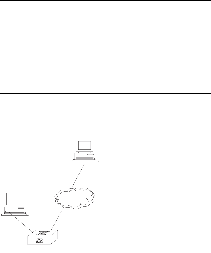
Managing the MAC Address Table 311
Execute the debugging command in user view to debug MAC address table
configuration.
Example: Configuring
MAC Address Table
Management
The user logs in to the switch through the console port to configure the address
table management. Set the address aging time to 500s and add a static address
00e0-fc35-dc71 to GigabitEthernet1/1/2 in vlan1.
Figure 2 Typical Configuration of Address Table Management
1Enter the system view of the switch.
<SW8800>system-view
2Add a MAC address (specify the native VLAN, port and state).
[SW8800]mac-address static 00e0-fc35-dc71 interface
GigabitEthernet1/1/2 vlan 1
3Set the address aging time to 500s.
[SW8800]mac-address timer 500
4Display the MAC address configurations in all views.
[SW8800]display mac-address interface Ethernet 1/1/2
MAC ADDR VLAN ID STATE PORT INDEX AGING TIME(s)
00-e0-fc-35-dc-71 1 Static Ethernet1/1/2 NOAGED
Table 20 Displaying and Debugging MAC Address Table
Operation Command
Display the information in the address table display mac-address [ static | dynamic ] [[
interface { interface-name | interface-type
interface-num } ] [ vlan vlan-id ] ]
Display the aging time of dynamic address
table entries
display mac-address aging-time
Display the dynamic MAC address learning
capability of the system and ports
display mac-address learning [
interface-type interface-num | interface-name
]
Enable the address table management
debugging
debugging mac-address
Disable the address table management
debugging
undo debugging mac-address
Console port
Network port
Internet
Switch

312 CHAPTER 11: SYSTEM MANAGEMENT
00-e0-fc-17-a7-d6 1 LearnedEthernet1/1/2 300
00-e0-fc-5e-b1-fb 1 Learned Ethernet1/1/2 300
00-e0-fc-55-f1-16 1 Learned Ethernet1/1/2 300
Managing Devices With device management, the Switch 8800 displays the current state and event
debugging information about the slots and physical devices. In addition, there is a
command for rebooting the system when a function failure occurs.
Configuring the Managing Devices is described in the following sections:
■Rebooting the Switch 8800
■Designating the File for the Next Boot
■Displaying Devices
Rebooting the Switch
8800
Perform the following configuration in user view.
Designating the File for
the Next Boot
In the case that there are several operational images in the flash memory, you can
use this command to designate the file (*.app) to use when the Switch 8800 is
booted.
Perform the following configuration in user view.
Tasks for designating the file for the next boot are described in the following
sections:
■Upgrading BootROM
■Resetting a Slot
■Setting the Slot Temperature Limit
Upgrading BootROM
You can use this command to upgrade the BootROM with the BootROM program
in the flash memory. This configuration task facilitates the remote upgrade. You
can upload the BootROM program file, from a remote end to the switch, by FTP
and then use this command to upgrade the BootROM on the modules.
Perform the following configuration in user view.
Tab le 21 Rebooting the Switch 8800
Operation Command
Reboot the Switch 8800 reboot
Tab le 22 Designating the APP for the next boot
Operation Command
Designate the APP for the next boot boot boot-loader file-url
Tab le 23 Upgrading BootROM
Operation Command
Upgrade BootROM boot BootROM file-url

Maintaining and Debugging the System 313
Resetting a Slot
The Switch 8800 allows the administrator to reset a slot in the system.
Perform the following configuration in user view.
The parameter slot-num ranges from 0 to 13, depending on the chassis. Setting
the parameter to 0 resets the fabric module, taking the same effect as resetting
the entire system. Setting the parameter from 1 through 13 resets the I/O modules
in the corresponding slots.
If you input reboot without specifying a slot number, the whole system will be
reset.
Setting the Slot Temperature Limit
When the temperature on a slot exceeds the preset limit, the Switch 8800 sounds
an alarm at the system and sends an SNMP trap to the network management
station.
Perform the following configuration in user view.
Displaying Devices Execute the display command in all views to display the device management
configuration, and to verify the configuration.
Maintaining and
Debugging the
System
This section includes descriptions of the following types of system maintenance ad
debugging:
■Configuring System Basics
■Displaying System Information and State
■Debugging the System
Table 24 Resetting a Slot
Operation Command
Reset a slot reboot [ slot slot-num ]
Table 25 Setting the Slot Temperature Limit
Operation Command
Set slot temperature limit temperature-limit slot down-value up-value
Table 26 Displaying Devices
Operation Command
Display the CPU display cpu [ slot slotnum ]
Display the module types and states of each
card
display device [ detail | { shelf shelf-no |
frame frame-no | slot slot-no }*]
Display the state of the built-in fans display fan [fan-id]
Display the information about the
environment
display environment
Display the used status of switch memory display memory [ slot slot-number ]
Display the state of the power display power [ power-ID ]

314 CHAPTER 11: SYSTEM MANAGEMENT
■Testing Tools for Network Connection
■Logging Function
Configuring System
Basics
This section describes the following basic system configuration tasks:
■Setting the System Name
■Setting the System Clock
■Setting the Time Zone
■Setting Daylight Saving Time
Setting the System Name
Perform the following commands in system view.
Setting the System Clock
Perform the following command in user view.
Setting the Time Zone
You can configure the name of the local time zone, and the time difference
between the local time and the standard Universal Time Coordinated (UTC).
Perform the following commands in user view.
By default, the UTC time zone is set.
Setting Daylight Saving Time
Use these commands to configure the start and end time of daylight saving time.
Perform this command in user view.
Tab le 27 Setting the System Name
Operation Command
Set the switch name sysname sysname
Restore the switch name to the default name undo sysname
Tab le 28 Setting the System Clock
Operation Command
Set the system clock clock datetime HH:MM:SS YYYY/MM/DD
Tab le 29 Setting the Time Zone
Operation Command
Set the local time clock timezone zone_name { add | minus }
HH:MM:SS
Restore to the default UTC time zone undo clock timezone
Tab le 30 Setting Daylight Saving Time
Operation Command
Set the name and range of daylight saving
time
clock summer-time zone_name { one-off |
repeating } start-time start-date end-time
end-date offset-time
Remove the setting of the summer time undo clock summer-time

Maintaining and Debugging the System 315
By default, daylight saving time is not set.
Displaying System
Information and State
The following display commands are used for displaying the system state and the
statistics information. For the display commands related to each protocol and
different ports, refer to the appropriate chapters.
Perform the following operations in all views.
Debugging the System Tasks for debugging the system are described in the following sections:
■Enabling and Disabling Terminal Debugging
■Displaying Diagnostic Information
Enabling and Disabling Terminal Debugging
The Switch 8800 provides various ways for debugging most of the supported
protocols and functions.
The following switches control the outputs of debugging information:
■The protocol debugging switch controls debugging output of a protocol.
■The terminal debugging switch controls debugging output on a specified user
screen.
Figure 3 illustrates the relationship between two switches.
Table 31 The Display Commands of the System
Operation Command
Display the system clock display clock
Display the system version display version
Display the terminal user display users [ all ]
Display the saved-configuration display saved-configuration
Display the current-configuration display current-configuration [ controller |
interface interface-type [ interface-number ] |
configuration [ configuration ] [ | { begin |
exclude | include } regular-expression ]
Display the state of the debugging display debugging [ interface {
interface-name | interface-type
interface-number } ] [ module-name ]
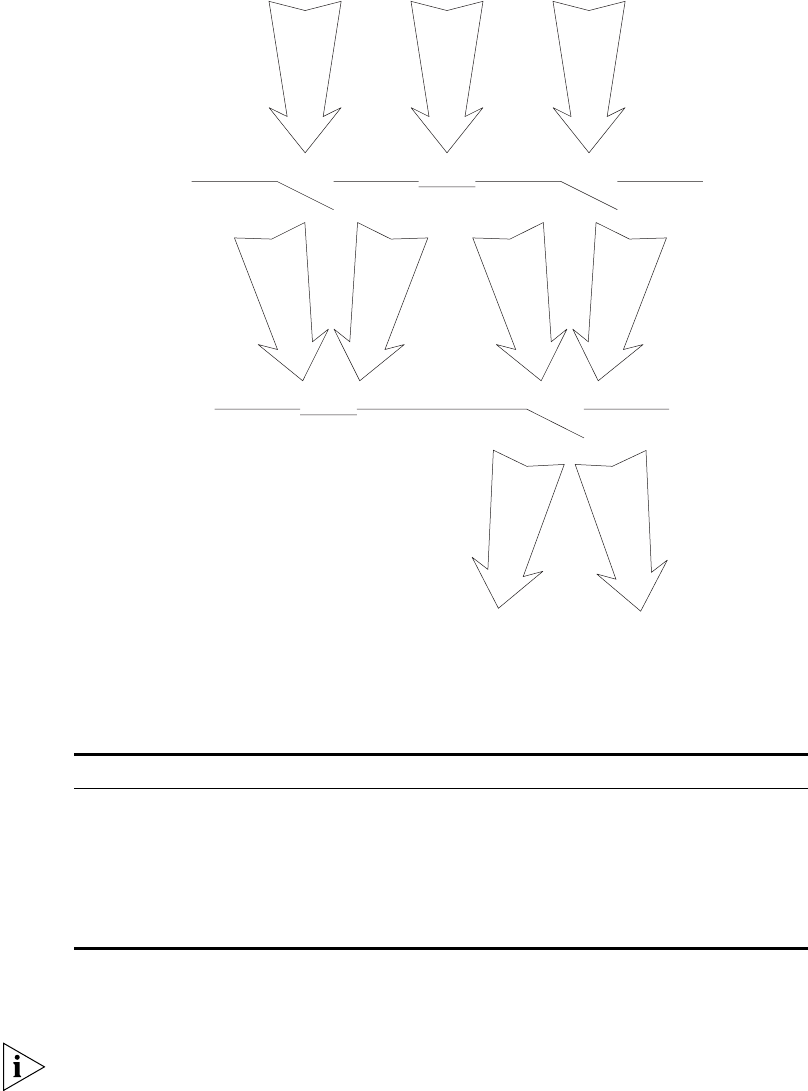
316 CHAPTER 11: SYSTEM MANAGEMENT
Figure 3 Debugging Output
You can use the following commands to control debugging.
Perform the following operations in user view.
For more about the usage and format of the debugging commands, refer to the
appropriate chapters.
Since the debugging output will affect the system operating efficiency, do not
enable the debugging command unnecessarily. Use the debugging all command,
especially, with caution. When the debugging is over, disable all debugging.
Displaying Diagnostic Information
You can collect information about the switch to locate the source of faults. Each
module has a corresponding display command, which makes it difficult to collect
all the information needed. In this case, use display diagnostic-information
command.
Tab le 32 Enabling and Disabling Debugging
Operation Command
Enable the protocol debugging debugging { all [ timeout interval ] |
module-name [ debugging-option ] }
Disable the protocol debugging undo debugging { all | { protocol-name |
function-name } [ debugging-option ] }
Enable the terminal debugging terminal debugging
Disable the terminal debugging undo terminal debugging
Debugging
information
Protocol debugging
switch
Screen output
switch OFF
OFF
ON
ON ON
123
13 13
13

Maintaining and Debugging the System 317
You can perform the following operations in all views.
To view the data later, enable saving a screen capture to a file.
Testing Tools for
Network Connection
The descriptions of testing tools for a network connection are found in the
following:
■Ping
■Tracert Command
Ping
The ping command can be used to check the network connection and to verify
whether the host can be reached.
Perform the following operation in user view.
The output of the ping command includes:
■The response to each ping message. If no response packet is received when
time is out,”Request time out” information appears. Otherwise, the data bytes,
the packet sequence number, TTL, and the round-trip time of the response
packet will be displayed.
■The final statistics, which include the:
■number of the packets the switch sent out and received
■packet loss ratio
■round-trip time in its minimum value, mean value and maximum value
Tracert Command
Tracert is used for testing the gateways from the source host to the destination. It
is used for checking if the network is connected and analyzing where faults occur
in the network.
The following list provides the tracert execution process:
1Tracert sends a packet with TTL value of 1.
2The first hop sends back an ICMP error message indicating that the packet cannot
be sent, for the TTL is timeout.
3Re-send the packet with TTL value of 2.
4The second hop returns the TTL timeout message.
Table 33 Displaying Diagnostic Information
Operation Command
Display diagnostic information display diagnostic-information
Table 34 The Ping Command
Operation Command
Support IP ping ping [ -a ip-address ] [-c count ] [ -d ] [ -i
{interface-type interface-num | interface-name
} ][ ip ] [ -n ] [ - p pattern ] [ -q ] [ -r ][ -s
packetsize ] [ -t timeout ] [ -v ] host

318 CHAPTER 11: SYSTEM MANAGEMENT
The process is repeated until the packet reaches the destination. The process is to
record the source address of each ICMP TTL timeout message to provide the route
of an IP packet to the destination.
Perform the following operation in user view.
Logging Function The syslog characterizes the behavior of the Switch 8800. It serves as an
information center of the system software modules. The logging system is
responsible for most of the information output, and also to make detailed
classification to filter the information efficiently. Coupled with the debugging
program, the syslog provides powerful support for the network administrators to
monitor the operational state of networks and to diagnose network failures.
The syslog of the Switch 8800 has the following features:
■Support for six different output destinations: console, monitor to Telnet
terminal, log buffer, loghost, trap buffer, and SNMP.
■The log is divided into 8 levels according to the significance of the event, and it
can be filtered based on the levels.
■The information can be classified in terms of the source modules, and the
information can be filtered by module.
■The output language can be selected between English and Chinese.
SYSLOG configuration includes tasks described in the following sections:
■Enabling and Disabling the Logging Function
■Setting the Output Channel of the Log
■Defining the Log Filtering Rules
■Configuring the SNMP Timestamp Output Format
■Displaying and Debugging the Syslog Function
For the above configuration, the log host is not configured on the switch. All other
configurations will take effect after enabling the logging function.
Enabling and Disabling the Logging Function
You can use the following commands to enable or disable the logging function.
Perform the following operation in system view.
Tab le 35 The Tracert Command
Operation Command
Trace a route tracert [ -f first-TTL ] [ -m max-TTL ] [ -p port ]
[ -q nqueries ] [ -w timeout ] host
Tab le 36 Enable/Disable the Logging Function
Operation Command
Enable the logging function. info-center enable
Disable the logging function. undo info-center enable

Maintaining and Debugging the System 319
By default, syslog is disabled. When syslog is enabled, system performance is
affected by the information classification and the output, especially when there is
a large amount of information to be processed.
Setting the Output Channel of the Log
The syslog of the Ethernet switch has six possible output destinations. Use the
configuration commands to specify the required channels for syslog output. All
the information will be filtered by the specified channel and then transmitted to
the configured destination. You can configure the channel and filtering
information for every destination to implement the filtering and redirection of
different information.
Use the following commands to configure the output channel of the log.
Perform the following configuration in system view.
Table 37 Log Output
Operation Command
Configure to output the information to the
Console
info-center console channel {
channel-number | channel-name }
Disable the output of the information to the
Console
undo info-center console channel
Configure to output the information to the
Telnet terminal or monitor
info-center monitor channel {
channel-number | channel-name }
Disable the output of the information to the
Telnet terminal or monitor
undo info-center monitor channel
Configure to output the information to the
logging buffer.
info-center logbuffer [ size buffersize ] [
channel { channel-number | channel-name } ]
Disable the output of the information to the
logging buffer.
undo info-center logbuffer [ channel | size
]
Configure to output the information to the
info-center loghost.
info-center loghost host-ip-addr [ channel {
channel-number | channel-name } ] [ facility
local-number ] [ language { chinese | english
} ]
Disable the output of the information to the
info-center loghost.
undo info-center loghost host-ip-addr
Set the address of the interface specified by
interface-name as the source address for
packets sent to loghost
info-center loghost source interface-name
Cancel the source address setting for the
packets sent to loghost
undo info-center loghost source
Configure to output the information to the
trap buffer.
info-center trapbuffer [ size buffersize ] [
channel { channel-number | channel-name } ]
Disable the output of the information to the
trap buffer.
undo info-center trapbuffer [ channel |
size ]
Configure to output the information to SNMP. info-center snmp channel { channel-number
| channel-name }
Disable the output of the information to
SNMP.
undo info-center snmp channel
Rename a channel specified by
channel-number as channel-name
info-center channel channel-number name
channel-name

320 CHAPTER 11: SYSTEM MANAGEMENT
The system assigns a channel in each output direction by default. See Tab le 38.
The six settings are independent from each other. The settings will take effect only
after enabling the information center.
Defining the Log Filtering Rules
The SYSLOG classifies the information into eight levels of severity. The log filtering
prevents the system from outputting information whose severity level is greater
than the set threshold. The more urgent the logging packet is, the lower its
severity level. The level for emergencies is 1, and the level for debugging is 8.
Therefore, when the threshold of the severity level is 8, the system will output all
information.
Use the following commands to define the filtering rules of the channels.
Perform the following operation in system view.
Tab le 38 Numbers and Names of the Channels for Log Output
Name Channel number Default channel name
Console 0console
Monitor 1monitor
Info-center loghost 2loghost
Trap buffer 3trapbuf
Logging buffer 4logbuf
SNMP 5snmpagent
Tab le 39 Syslog-Defined Severity
Severity Description
1 Emergencies The extremely emergent errors
2 Alerts The errors that need to be corrected
immediately.
3 Critical Critical errors
4 Errors The errors that need to be addressed but are
not critical
5 Warnings Warning, there might be an error
6 Notifications The information should be read
7 Informational Common prompting information
8 Debugging Helpful information for debugging
Tab le 40 Define the Filtering Rules of the Channels
Operation Command
Add the filtering record about a certain type
of information in a module to the information
channel
info-center source { module-name | default
} channel { channel-number | channel-name }
[ { log | trap | debug } * { level severity |
state state ] } *
Delete the filtering record about a certain type
of information in a module or all the modules
from the channel
undo info-center source { modu-name |
default } channel { channel-number |
channel-name }

Maintaining and Debugging the System 321
module-name specifies the module name. level refers to the severity levels and
severity specifies the severity level of information. The information with the level
below it will not be output. channel-number specifies the channel number and
channel-name specifies the channel name.
Every channel has been set with a default record, whose module name is default
and the module number is 0xffff0000. However, for different channels, the default
record may have different default settings of log, trap and debugging. When there
is no specific configuration record for a module in the channel, use the default
one.
When there is more than one Telnet user or monitor user at the same time, some
configuration parameters are shared among the users, such as module-based
filtering settings and the severity threshold. When you modify these settings, the
changes affect all users.
Configuring the SNMP Timestamp Output Format
Perform the following operation in system view.
Displaying and Debugging the Syslog Function
After performing the syslog configuration, execute the display command in all
views to display the configuration and to verify the effect of the configuration.
Execute the reset command in user view to clear the statistics of the syslog
module. Execute the debugging command in user view to debug the syslog
module.
Perform the following configuration in system view.
Table 41 Configuring the SNMP Timestamp Output Format
Operation Command
Configure the SNMP Timestamp Output
Format
info-center timestamp { log | trap |
debugging } { boot | date | none }
Disable the output of the timestamp field undo info-center timestamp { log | trap |
debugging }
Table 42 Displaying and Debugging the Syslog Function
Operation Command
View details about the information channel display channel [ channel-number |
channel-name ]
View the configuration of the system log and
the information recorded in the memory
buffer
display info-center
Reset the information in the log buffer reset logbuffer
Reset the information in the trap buffer reset trapbuffer
Enable terminal log information display terminal logging
Disable terminal log information display undo terminal logging
Enable the log debugging/log/trap on the
terminal monitor
terminal monitor
Disable the log debugging/log/trap on the
terminal monitor
undo terminal monitor
Enable terminal trap information display terminal trapping
Disable terminal trap information display undo terminal trapping

322 CHAPTER 11: SYSTEM MANAGEMENT
SNMP The Simple Network Management Protocol (SNMP) is used for transmitting
management information between any two nodes. In this way, network
administrators can easily search and modify the information on any node on the
network. They can also locate faults promptly and implement the fault diagnosis,
capacity planning, and report generating. SNMP adopts the polling mechanism
and provides the most basic function set. It is most applicable to the small-sized,
fast-speed, and low-cost environment. It only requires the unverified transport
layer protocol UDP, and is widely supported by many other products.
In terms of structure, SNMP can be divided into two parts, NMS and Agent. NMS
(Network Management Station) is the workstation for running the client program.
At present, the commonly used NM platforms include Sun NetManager and IBM
NetView. The agent is the server software operated on network devices. NMS can
send GetRequest, GetNextRequest, and SetRequest messages to the agent. Upon
receiving the requests from the NMS, the agent will perform a read or write
operation according to the message types, and generate and return the response
message to NMS. On the other hand, the agent will send a trap message on its
own initiative to NMS to report events whenever the device encounters any
abnormalities.
Configuring SNMP is described in the following sections:
■SNMP Versions and Supported MIB
■Configuring SNMP
SNMP Versions and
Supported MIB
To uniquely identify the management variables of a device in SNMP messages,
SNMP adopts the hierarchical naming scheme to identify the managed objects. It
is like a tree. A tree node represents a managed object, as shown in the figure
below. Thus the object can be identified with the unique path starting from the
root.
Figure 4 Architecture of the MIB Tree
The MIB (Management Information Base) is used to describe the hierarchical
architecture of the tree, and is the set defined by the standard variables of the
monitored network device. In the above figure, the managed object B can be
uniquely specified by a string of numbers {1.2.1.1}. The number string is the
Object Identifier of the managed object.
1
12
2
2
65
1
1
A
B

SNMP 323
The current SNMP Agent of Ethernet switch supports SNMP V1, V2C and V3. The
MIBs supported are listed in the following table.
Configuring SNMP Configuring SNMP includes tasks that are described in the following sections:
■Setting the Community Name
■Enabling and Disabling the SNMP Agent to Send a Trap
■Setting the Destination Address of a Trap
■Setting the Lifetime of the Trap Message
■Setting SNMP Information
■Setting the Engine ID of a Local or Remote Device
■Setting and Deleting an SNMP Group
■Setting the Source Address of the Trap
■Adding and Deleting a User to or from an SNMP Group
■Creating and Updating View Information or Deleting a View
■Setting the Size of an SNMP Packet Sent or Received by an Agent
■Enabling and Disabling Transmission of Trap Information
■Disabling the SNMP Agent
■Displaying and Debugging SNMP
Setting the Community Name
SNMP v1, and SNMP v2C, and SNMP v3 use the community name authentication
scheme. An SNMP message that does not comply with the community name that
is accepted by the device is discarded. An SNMP community is named with a
character string, which is called the community name. Communities can have
read-only or read-write access modes. A community with read-only authority can
Table 43 MIBs Supported by the Switch 8800
MIB Attribute MIB Content References
Public MIB MIB II based on TCP/IP network
device
RFC1213
BRIDGE MIB RFC1493
RFC2675
RIP MIB RFC1724
RMON MIB RFC2819
Ethernet MIB RFC2665
OSPF MIB RFC1253
IF MIB RFC1573
Private MIB DHCP MIB
QACL MIB
ADBM MIB
RSTP MIB
VLAN MIB
Device management
Interface management

324 CHAPTER 11: SYSTEM MANAGEMENT
only query the device information, whereas the community with read-write
authority can also configure the device.
Use the following commands to set the community name.
Perform the following configuration in system view.
Enabling and Disabling the SNMP Agent to Send a Trap
The managed device transmits a trap without a request to the NMS to report
critical and urgent events, such as a restart.
You can use the following commands to enable or disable the managed device to
transmit a trap message.
Perform the following configuration in system view.
Setting the Destination Address of a Trap
You can use the following commands to set or delete the destination address of
the trap.
Perform the following configuration in system view.
The authentication parameter specifies that the packet is authenticated without
encryption. This parameter is supported only in SNMP V3.
Tab le 44 Setting the Community Name
Operation Command
Set the community name and the access
authority
snmp-agent community { read | write }
community-name [ [ mib-view view-name ] [
acl acl-list ] ]
Remove the community name and the access
authority
undo snmp-agent community
community-name
Tab le 45 Enabling and Disabling an SNMP Agent to Send a Trap
Operation Command
Enable to send a trap snmp-agent trap enable [ standard [
authentication ] [ coldstart ] [ linkdown ] [
linkup ] [ warmstart ] ]
Disable to send a trap undo snmp-agent trap enable [ standard [
authentication ] [ linkdown ] [ linkup ] [
coldstart ] [ warmstart ] ]
Tab le 46 Setting the Destination Address of a Trap
Operation Command
Set the destination address of trap snmp-agent target-host trap address
udp-domain host-addr [ udp-port
udp-port-number ] params securityname
community-string [ v1 | v2c | v3 {
authentication | privacy } ]
Delete the destination address of trap undo snmp-agent target-host host-addr
securityname community-string

SNMP 325
The privacy parameter specifies that the packet is authenticated and encrypted.
This parameter is supported only in SNMP V3.
Setting the Lifetime of the Trap Message
You can use the following command to set lifetime of a trap message. A trap
message that exists longer than the set lifetime will be dropped.
Perform the following configuration in system view.
By default, the lifetime of a trap message is 120 seconds.
Setting SNMP Information
The SNMP system information includes the character string sysContact (system
contact), the character string describing the system location, and the version
information for SNMP in the system.
Use the following commands to set the system information.
Perform the following configuration in system view.
By default, syslocation is specified as “Marlborough MA”.
Setting the Engine ID of a Local or Remote Device
Use the following commands to set the engine ID of a local or remote device.
Perform the following configuration in system view.
By default, the engine ID is expressed as enterprise No. + device information. The
device information can be IP address, MAC address, or user-defined text.
Setting and Deleting an SNMP Group
Use the following commands to set or delete an SNMP group.
Table 47 Setting the Lifetime of the Trap Message
Operation Command
Set lifetime of Trap message snmp-agent trap life seconds
Restore lifetime of Trap message undo snmp-agent trap life
Table 48 Setting SNMP System Information
Operation Command
Set SNMP system information snmp-agent sys-info { contact sysContact |
location syslocation | version { { v1 | v2c | v3
] * | all } }
Restore the default SNMP system information
of the Ethernet switch
undo snmp-agent sys-info [ { contact |
location }* | version { { v1 | v2c | v3 ] * | all }
]
Table 49 Setting the Engine ID of a Local or Remote Device
Operation Command
Set the engine ID of the device snmp-agent local-engineid engineid
Restore the default engine ID of the device. undo snmp-agent local-engineid engineid

326 CHAPTER 11: SYSTEM MANAGEMENT
Perform the following configuration in system view.
The authentication parameter specifies that the packet is authenticated without
encryption. This parameter is supported only in SNMP V3.
The privacy parameter specifies that the packet is authenticated and encrypted.
This parameter is supported only in SNMP V3.
Setting the Source Address of the Trap
Use the following commands to set or remove the source address of the trap.
Perform the following configuration in system view.
Adding and Deleting a User to or from an SNMP Group
Use the following commands to add or delete a user to or from an SNMP group.
Perform the following configuration in system view.
Tab le 50 Setting and Deleting an SNMP Group
Operation Command
Setting an SNMP group snmp-agent group group-name { v1 | v2c } [
read-view read-view ] [ write-view
write-view ] [ notify-view notify-view ] [ acl
acl-list ]
snmp-agent group group-name v3 [
authentication | privacy ] [ read-view
read-view ] [ write-view write-view ] [
notify-view notify-view ] [ acl acl-list ]
Deleting an SNMP group undo snmp-agent group group-name { v1 |
v2c }
undo snmp-agent group group-name v3 [
authentication | privacy ]
Tab le 51 Setting the Source Address of the Trap
Operation Command
Set the Source Address of Trap snmp-agent trap source interface-name
interface-num
Remove the source address of trap undo snmp-agent trap source
Tab le 52 Adding and Deleting a User to or from an SNMP Group
Operation Command
Add a user to an SNMP group snmp-agent usm-user { v1 | v2c } username
groupname [ acl acl-list ]
snmp-agent usm-user v3 username
groupname [ authentication-mod { md5 |
sha } auth_password [ privacy-mod { des56
priv_password } ] ] acl acl-list
Delete a user from an SNMP group undo snmp-agent usm-user { v1 | v2c }
username groupname
undo snmp-agent usm-user v3 username
groupname { local | engineid engine-id }
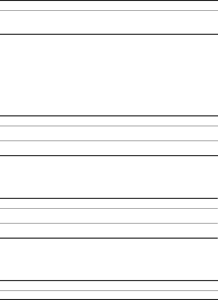
SNMP 327
The authentication-mode parameter specifies the use of authentication. The
privacy-mode parameter specifies the use of authentication and encryption. This
parameter is supported only in SNMP V3.
For details, see the Switch 8800 Command Reference Guide.
Creating and Updating View Information or Deleting a View
Use the following commands to create, update the information of views, or delete
a view.
Perform the following configuration in system view.
Setting the Size of an SNMP Packet Sent or Received by an Agent
Use the following commands to set the size of SNMP packet sent or received by an
agent.
The agent can receive or send the SNMP packets ranging from 484 bytes to 17940
bytes. By default, the size of an SNMP packet is 1500 bytes.
Perform the following configuration in system view.
Enabling and Disabling Transmission of Trap Information
To enable or disable transmission of trap information, perform the following
configuration in Ethernet port view.
Disabling the SNMP Agent
To disable the SNMP Agent, perform the following configuration in system view.
Table 53 Creating and Updating View Information or Deleting a View
Operation Command
Create or update view information snmp-agent mib-view { included |
excluded } view-name oid-tree
Delete a view undo snmp-agent mib-view view-name
Table 54 Setting the Size of an SNMP Packet Sent or Received by an Agent
Operation Command
Set the size of an SNMP packet set or received
by an agent
snmp-agent packet max-size byte-count
Restore the default size of an SNMP packet
sent or received by an agent
undo snmp-agent packet max-size
Table 55 Enable/Disable Transmission of Trap Information
Operation Command
Enable the current port to transmit the trap
information
enable snmp trap updown
Disable the current port from transmitting trap
information
undo enable snmp trap updown
Table 56 Disabling SNMP Agent
Operation Command
Disable snmp agent undo snmp-agent

328 CHAPTER 11: SYSTEM MANAGEMENT
If a user disables an NMP Agent, it is enabled whatever snmp-agent command is
configured.
Displaying and Debugging SNMP
Execute the display command to view the SNMP configuration and to verify the
effect of the configuration. Execute the debugging command in user view to
debug the SNMP configuration.
Example: SNMP
Configuration
The IP address of NMS is 129.102.149.23 and the IP address of the VLAN interface
on the switch is 129.102.0.1.
Perform the following configurations on the switch:
■Set the community name and access authority
■Set the administrator ID, contact and switch location
■Enable the switch to send a trap packet.
Tab le 57 Displaying and Debugging SNMP
Operation Command
Display the statistics information about SNMP
packets
display snmp-agent statisitcs
Display the engine ID of the active device display snmp-agent { local-engineid |
remote-engineid }
Display the group name, the security mode,
the states for all types of views, and the
storage mode of each group of the switch.
display snmp-agent group
Display the names of all users in the group
user table
display snmp-agent usm-user [ { local | {
engineid engineid } } | username groupname ]
Display the current community name display snmp-agent community [ read |
write ]
Display the current MIB view display snmp-agent mib-view [ exclude |
include | viewname mib-view ]
Display the contact character string of the
system
display snmp-agent sys-info contact
Display the location character string of the
system
display snmp-agent sys-info location
Display the version character string of the
system
display snmp-agent sys-info version
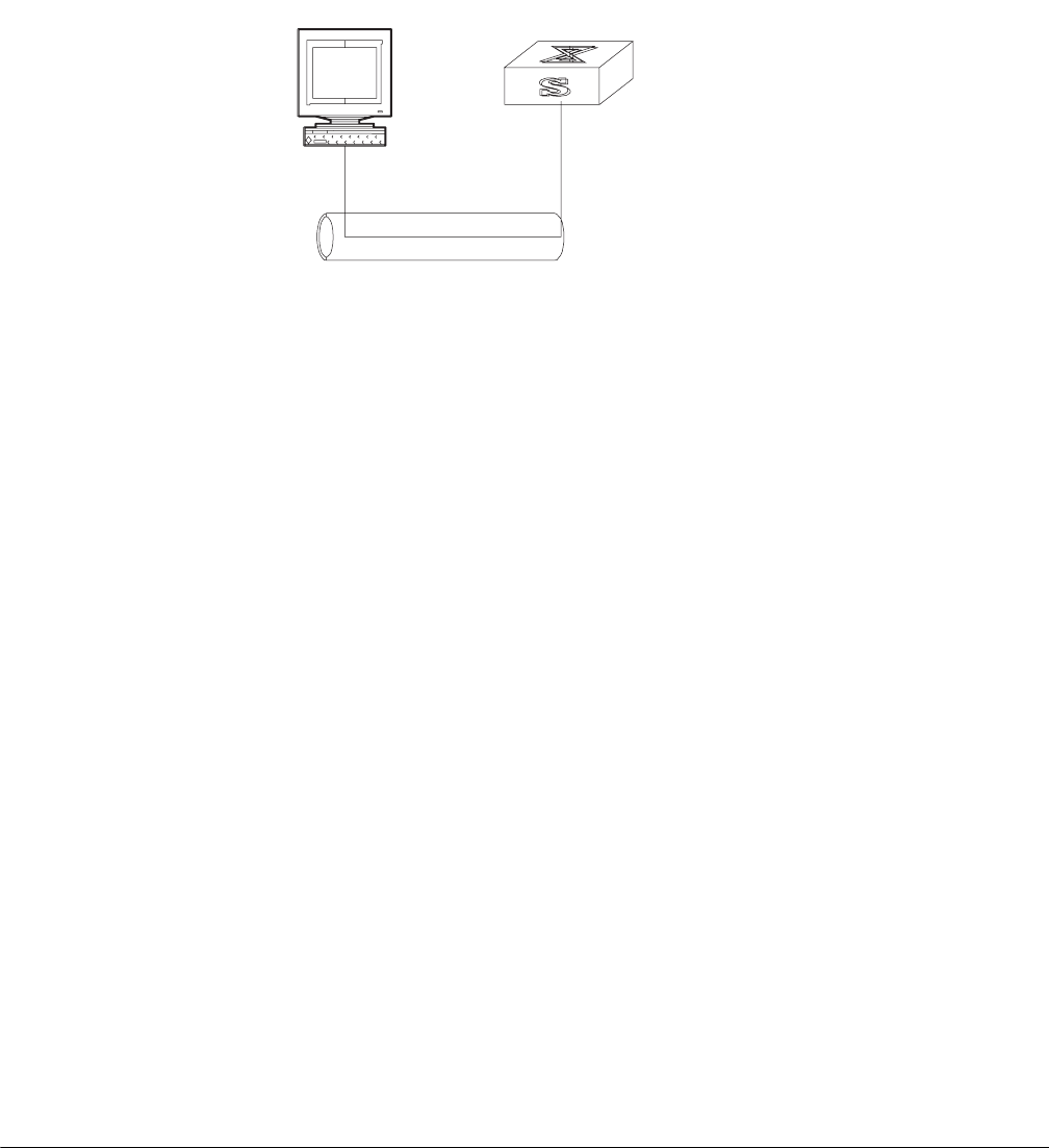
RMON 329
Figure 5 SNMP Configuration Example
1Enter the system view.
<SW8800>system-view
2Set the community name, group name, and user.
[SW8800]snmp-agent sys-info version all
[SW8800]snmp-agent community write public
[SW8800]snmp-agent mib include internet 1.3.6.1
[SW8800]snmp-agent group v3 managev3group write internet
[SW8800]snmp-agent usm v3 managev3user managev3group
3Set the administrator ID, contact and the physical location of the Ethernet switch.
[SW8800]snmp-agent sys-info contact Mr.Smith-Tel:3306
[SW8800]snmp-agent sys-info location telephone-closet, 3rd-floor
4Set the VLAN interface 2 as the interface used by network management. Add
Ethernet port 2/1/3 to the VLAN 2. This port will be used for network
management. Set the IP address of VLAN interface 2 as 129.102.0.1.
[SW8800]vlan 2
[SW8800-vlan2]port ethernet 2/1/3
[SW8800-vlan2]interface vlan 2
[SW8800-Vlan-interface2]ip address 129.102.0.1 255.255.255.0
5Set the administrator ID, contact and the physical location of the Ethernet switch.
[SW8800]snmp-agent sys-info contact Mr.Smith-Tel:3306
[SW8800]snmp-agent sys-info location telephone-closet,3rd-floor
6Enable the SNMP agent to send the trap to Network Management Station whose
IP address is 129.102.149.23. The SNMP community is public.
[SW8800]snmp-agent trap enable standard authentication
[SW8800]snmp-agent trap enable standard coldstart
[SW8800]snmp-agent trap enable standard linkup
[SW8800]snmp-agent trap enable standard linkdown
[SW8800]snmp-agent target-host trap address udp-domain
129.102.149.23 udp-port 5000 params securityname public
RMON Remote Network Monitoring (RMON) is an IETF-defined MIB. It is the most
important enhancement to the MIB II standard. It is used for monitoring the data
traffic on a segment and even on a whole network. It is one of the most widely
used network management standards.
RMON is based on the SNMP architecture and is compatible with the existing
SNMP framework, so it is not necessary to adjust the protocol. RMON includes
NMS
129.102.149.23 129.102.0.1
Ethernet
330 CHAPTER 11: SYSTEM MANAGEMENT
NMS and the agent running on the network devices. On the network monitor or
detector, RMON agent tracks and accounts for different traffic information on the
segment connected to its port. For example, the total number of packets on a
segment in a certain period of time or that of the correct packets sent to a host.
RMON helps the SNMP monitor the remote network device more actively and
effectively, which provides a highly efficient means for monitoring subnet
operations. RMON can reduce communication traffic between the NMS and the
agent, thus facilitating an effective management over large interconnected
networks.
RMON allows multiple monitors. It can collect data in two ways.
1The first way is with a special RMON probe. NMS directly obtains the management
information from the RMON probe and controls the network resource. In this way,
it obtains all the information of RMON MIB.
2The second way is to implant the RMON Agent directly into the network devices,
such as routers, switches, hubs, and so on, so that the devices become network
facilities with RMON probe functions. RMON NMS uses the basic SNMP
commands to exchange data information with the SNMP Agent and to collect NM
information. However, not all the data of the RMON MIB can be obtained with this
method, depending on resources. In most cases, only four groups of information
can be collected. The four groups are: trap information, event information, history
information and statistics information.
The Switch 8800 implements RMON using the second method. With the
RMON-supported SNMP agent running on the network monitor, NMS can obtain
such information as the overall traffic of the segment connected to the managed
network device port, the error statistics and performance statistics, thereby
implementing the management (usually remote) over the network.
Configuring RMON RMON configuration includes tasks described in the following sections:
■Adding and Deleting an Entry to or from the Alarm Table
■Adding and Deleting an Entry to or from the Event Table
■Adding and Deleting an Entry to or from the History Control Table
■Adding and Deleting an Entry to or from the Extended RMON Alarm Table
■Adding and Deleting an Entry to or from the Statistics Table
■Displaying the RMON Configuration
Adding and Deleting an Entry to or from the Alarm Table
RMON alarm management can monitor the specified alarm variables, such as,
statistics on a port. When a value of the monitored data exceeds the defined
threshold, an alarm event will be generated. Generally, the event will be recorded
in the device log table and a Trap message will be sent to NMS. The events are
defined in event management. The alarm management includes browsing, adding
and deleting alarm entries.
Use the following commands to add or delete an entry to or from the alarm table.

RMON 331
Perform the following configuration in system view.
Adding and Deleting an Entry to or from the Event Table
RMON event management defines the event ID and handling of the event by
keeping logs, sending trap messages to NMS, or performing both at the same
time.
Use the following commands to add or delete an entry to or from the event table.
Perform the following configuration in system view.
Adding and Deleting an Entry to or from the History Control Table
The history data management helps you set the history data collection, periodical
data collection, and storage of the specified ports. The sampling information
includes the utilization ratio, error counts, and the total number of packets.
Use the following commands to add or delete an entry to or from the history
control table.
Perform the following configuration in Ethernet port view.
Adding and Deleting an Entry to or from the Extended RMON Alarm Table
You can use the command to add or delete an entry to or from the extended
RMON alarm table.
Table 58 Adding or Delete an Entry to or from the Alarm Table
Operation Command
Add an entry to the alarm table. rmon alarm entry-number alarm-variable
sampling-time { delta | absolute }
rising-threshold threshold-value1
event-entry1 falling-threshold
threshold-value2 event-entry2 [ owner text ]
Delete an entry from the alarm table. undo rmon alarm entry-number
Table 59 Add or Delete an Entry to or from the Event Table
Operation Command
Add an entry to the event table rmon event event-entry [ description string ]
{ log | trap trap-community | log-trap
log-trapcommunity | none } [ owner
rmon-station ]
Delete an entry from the event table undo rmon event event-entry
Table 60 Adding or Deleting an Entry to or from the History Control Table
Operation Command
Add an entry to the history control table rmon history entry-number buckets number
interval sampling-interval [ owner text-string
]
Delete an entry from the history control table undo rmon history entry-number

332 CHAPTER 11: SYSTEM MANAGEMENT
Perform the following configuration in system view.
Adding and Deleting an Entry to or from the Statistics Table
The RMON statistics management concerns port usage monitoring and error
statistics when using the ports. The statistics include collision, CRC and queuing,
undersize packets or oversize packets, timeout transmission, fragments,
broadcast, multicast and unicast messages, and the usage ratio of bandwidth.
Use the following commands to add or delete an entry to or from the statistics
table.
Perform the following configuration in Ethernet port view.
Displaying the RMON Configuration
Execute the display command in all views to display the RMON configuration, and
to verify the configuration.
Example: RMON
Configuration
Set an entry in the RMON Ethernet statistics table for Ethernet port performance,
which is convenient for network administrators’ query.
Tab le 61 Add or Delete an Entry to or from the Extended RMON AlarmTable
Operation Command
Add an entry to the extended RMON alarm
table
rmon prialarm entry-number alarm-var [
alarm-des ] sampling-timer { delta | absolute
| changeratio } rising-threshold
threshold-value1 event-entry1
falling-threshold threshold-value2
event-entry2 entrytype { forever | cycle
cycle-period } [ owner text ]
Delete an entry from the extended RMON
alarm table
undo rmon prialarm entry-number
Tab le 62 Add or Delete an Entry to or from the Statistics Table
Operation Command
Add an entry to the statistics table rmon statistics entry-number [ owner
text-string ]
Delete an entry from the statistics table undo rmon statistics entry-number
Tab le 63 Displaying and Debugging RMON
Operation Command
Display the RMON statistics display rmon statistics [ port-num ]
Display the history information of RMON display rmon history [ port-num ]
Display the alarm information of RMON display rmon alarm [ alarm-table-entry ]
Display the extended alarm information of
RMON
display rmon prialarm [ prialarm-table-entry
]
Display the RMON event display rmon event [ event-table-entry ]
Display the event log of RMON display rmon eventlog [ event-number ]
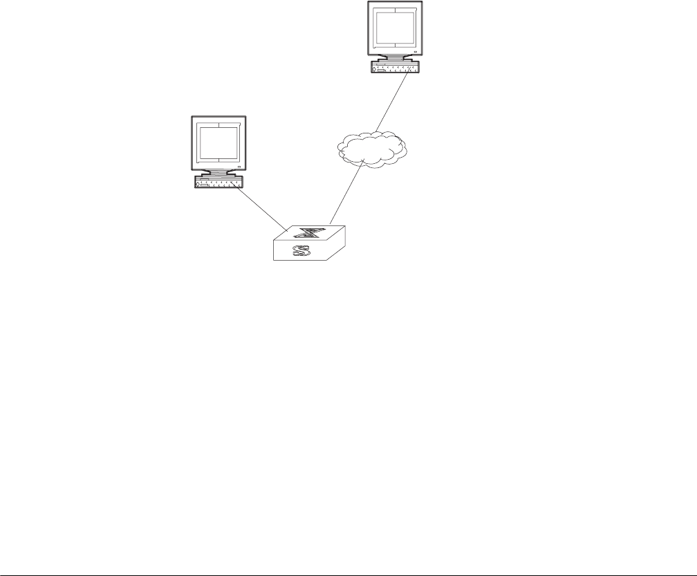
NTP 333
Figure 6 RMON Configuration Networking
1Configure RMON.
[SW8800-Ethernet2/1/1]rmon statistics 1 owner 3com-rmon
2View the configurations in user view.
<SW8800>display rmon statistics Ethernet2/1/1
Statistics entry 1 owned by 3com-rmon is VALID.
Gathers statistics of interface Ethernet2/1/1. Received:
octets : 270149,packets : 1954
broadcast packets :1570 ,multicast packets:365
undersized packets :0 ,oversized packets:0
fragments packets :0 ,jabbers packets :0
CRC alignment errors:0 ,collisions :0
Dropped packet events (due to lack of resources):0
Packets received according to length (in octets):
64 :644 , 65-127 :518 , 128-255 :688
256-511:101 , 512-1023:3 , 1024-1518:0
NTP As the network topology gets more and more complex, it becomes important to
synchronize the clocks of the equipment on the entire network. Network Time
Protocol (NTP) is a TCP/IP feature that advertises the accurate time throughout the
network.
NTP ensures the consistency of the following applications:
■Synchronizing the clock between two systems for incremental backup between
the backup server and client.
■Referencing the same clock and guaranteeing correct processing for multiple
systems that coordinate to process a complex event.
■Guaranteeing the normal operation of the inter-system (Remote Procedure
Call).
■Recording an application when a user logs into a system, a file is modified, or
some other operation is performed.
Figure 7 illustrates the basic operating principle of NTP:
Console port
Network port
Switch
Internet
334 CHAPTER 11: SYSTEM MANAGEMENT
Figure 7 Basic Operating Principle of NTP
In page 334, Switch A and Switch B are connected to the Ethernet port. They have
independent system clocks. Before implementing automatic clock synchronization
on both switches, we assume that:
■Before synchronizing the system clocks on Switch A and B, the clock on Switch
A is set to 10:00:00am, and the clock on B is set to 11:00:00am.
■Switch B serves as an NTP time server and Switch A synchronizes the local clock
with the clock of B.
■It takes 1 second to transmit a data packet from either A or B to the opposite
end.
The system clocks are synchronized as follows:
■Switch A sends an NTP packet to Switch B. The packet carries the timestamp
10:00:00am (T1) that tells when it left Switch A.
■When the NTP packet arrives at Switch B, Switch B adds a local timestamp
11:00:01am (T2) to it.
■When the NTP packet leaves Switch B, Switch B adds another local timestamp
11:00:02am (T3) to it.
■When Switch A receives the acknowledgement packet, it adds a new
timestamp 10:00:03am (T4) to it.
Next, E Switch A collects enough information to calculate the following two
important parameters:
■The delay for a round trip of an NTP packet traveling between the Switch A and
B: Delay= (T4-T1) - (T3-T2).
■Offset of Switch A clock relative to Switch B clock: offset= ( (T2-T1) + (T3-T4) )
/2.
NTP 335
Switch A uses this information to set the local clock and to synchronize it with the
clock on Switch B.
Configuring NTP is described in the following sections:
■Configuring NTP
■NTP Configuration Examples
Configuring NTP NTP configuration includes the tasks described in the following sections:
■Configuring NTP Operating Mode
■Configuring NTP ID Authentication
■Setting the NTP Authentication Key
■Setting the Specified Key to Be Reliable
■Designating an Interface to Transmit the NTP Message
■Setting the NTP Master Clock
■Enabling or Disabling an Interface to Receive an NTP Message
■Setting the Authority to Access a Local Switch
■Setting Maximum Local Sessions
■Displaying and Debugging NTP
Configuring NTP Operating Mode
The Switch 8800 can only serve as an NTP client but not as an NTP server.
You can set the NTP operating mode of the Switch 8800 according to its location
in the network, and the network structure. For example, you can set a remote
server as the time server of the local equipment. In this case the local Switch 8800
works as an NTP client. If you set a remote server as a peer of the local Switch
8800, the local equipment operates in symmetric active mode. If you configure an
interface on the local switch to transmit NTP broadcast packets, the local switch
will operate in broadcast mode. If you configure an interface on the local switch to
receive NTP broadcast packets, the local switch will operate in broadcast client
mode. If you configure an interface on the local switch to transmit NTP multicast
packets, the local switch will operate in multicast mode. You may also configure
an interface on the local switch to receive NTP multicast packets, the local switch
will operate in multicast client mode.
The following sections describe how to configure NTP modes:
■Configuring NTP Server Mode
■Configuring NTP Peer Mode
■Configuring NTP Broadcast Server Mode
■Configuring NTP Broadcast Client Mode
■Configuring NTP Multicast Server Mode
■Configuring NTP Multicast Client Mode
Configuring NTP Server Mode Set a remote server whose IP address is
ip-address as the local time server. ip-address specifies a host address other than a

336 CHAPTER 11: SYSTEM MANAGEMENT
broadcast, multicast, or reference clock IP address. In this case, the local switch
operates in client mode. In this mode, only the local client synchronizes its clock
with the clock of the remote server, while the reverse synchronization will not
happen.
Perform the following configurations in system view.
NTP version number number ranges from 1 to 3 and defaults to 3; the
authentication key ID keyid ranges from 0 to 4294967295; interface-name or
interface-type interface-number specifies the IP address of an interface, from
which the source IP address of the NTP packets sent from the local switch to the
time server will be taken; priority indicates the time server will be the first choice.
Configuring NTP Peer Mode Set a remote server whose IP address is
ip-address as the peer of the local equipment. In this case, the local equipment
operates in symmetric active mode. ip-address specifies a host address other than
a broadcast, multicast, or reference clock IP address. In this mode, both the local
switch and the remote server can synchronize their clocks with the clock of the
opposite end.
Perform the following configurations in system view.
NTP version number number ranges from 1 to 3 and defaults to 3; the
authentication key ID keyid ranges from 1 to 4294967295; interface-name or
interface-type interface-number specifies the IP address of an interface, from
which the source IP address of the NTP packets sent from the local switch to the
peer will be taken; priority indicates that the peer will be the first choice for time
server.
Configuring NTP Broadcast Server Mode Designate an interface on the local
switch to transmit NTP broadcast packets. In this case, the local equipment
operates in broadcast mode and serves as a broadcast server to broadcast
messages to its clients regularly.
Tab le 64 Configuring NTP Time Server
Operation Command
Configure NTP time server ntp-service unicast-server ip-address [
version number | authentication-keyid
keyid | source-interface { interface-name |
interface-type interface-number } | priority ]*
Cancel NTP server mode undo ntp-service unicast-server ip-address
Tab le 65 Configuring NTP Peer Mode
Operation Command
Configure NTP peer mode ntp-service unicast-peer ip-address [
version number | authentication-key keyid |
source-interface { interface-name |
interface-type interface-number } | priority ]*
Cancel NTP peer mode undo ntp-service unicast-peer ip-address

NTP 337
Perform the following configurations in VLAN interface view.
NTP version number number ranges from 1 to 3 and defaults to 3; the
authentication key ID keyid ranges from 0 to 4294967295. This command can
only be configured on the interface where the NTP broadcast packets will be
transmitted.
Configuring NTP Broadcast Client Mode Designate an interface on the local
switch to receive NTP broadcast messages and operate in broadcast client mode.
The local switch listens to the broadcast from the server. When it receives the first
broadcast packets, it starts a brief client/server mode to switch messages with a
remote server for estimating the network delay. Thereafter, the local switch enters
broadcast client mode and continues listening to the broadcast, and synchronizes
the local clock according to the arrived broadcast message.
Perform the following configurations in VLAN interface view.
This command can only be configured on the interface where the NTP broadcast
packets are received.
Configuring NTP Multicast Server Mode Designate an interface on the local
switch to transmit NTP multicast packets. In this case, the local equipment
operates in multicast mode and serves as a multicast server to multicast messages
to its clients regularly.
Perform the following configurations in VLAN interface view.
NTP version number number ranges from 1 to 3 and defaults to 3; the
authentication key ID keyid ranges from 0 to 4294967295; ttl-number of the
multicast packets ranges from 1 to 255; And the multicast IP address defaults to
224.0.1.1.
Table 66 Configuring NTP Broadcast Server Mode
Operation Command
Configure NTP broadcast server mode ntp-service broadcast-server [
authentication-keyid keyid ] [ version
number ]
Cancel NTP broadcast server mode undo ntp-service broadcast-server
Table 67 Configuring NTP Broadcast Client Mode
Operation Command
Configure NTP broadcast client mode ntp-service broadcast-client
Disable NTP broadcast client mode undo ntp-service broadcast-client
Table 68 Configuring NTP Multicast Server Mode
Operation Command
Configure NTP multicast server mode ntp-service multicast-server [ ip-address ] [
authentication-keyid keyid ] [ ttl ttl-number
] [ version number ]
Cancel NTP multicast server mode undo ntp-service multicast-server

338 CHAPTER 11: SYSTEM MANAGEMENT
This command can only be configured on the interface where the NTP multicast
packet is transmitted.
Configuring NTP Multicast Client Mode Designate an interface on the local
switch to receive NTP multicast messages and operate in multicast client mode.
The local switch listens to the multicast from the server. When it receives the first
multicast packets, it starts a brief client/server mode to switch messages with a
remote server for estimating the network delay. Thereafter, the local switch enters
multicast client mode and continues listening to the multicast and synchronizes
the local clock by the arrived multicast message.
Perform the following configurations in VLAN interface view.
Multicast IP address ip-address defaults to 224.0.1.1. This command can only be
configured on the interface where the NTP multicast packets is received.
Configuring NTP ID Authentication
Enable NTP authentication, set the MD5 authentication key, and specify the
reliable key. A client will synchronize itself by a server only if the server can provide
a reliable key.
Perform the following configurations in system view.
Setting the NTP Authentication Key
This configuration task sets the NTP authentication key.
Perform the following configurations in system view.
Key number number ranges from 1 to 4294967295; the key value contains 1 to
32 ASCII characters.
Setting the Specified Key to Be Reliable
This configuration task is to set the specified key as reliable.
Tab le 69 Configuring NTP Multicast Client Mode
Operation Command
Configure NTP multicast client mode ntp-service multicast-client [ ip-address ]
Cancel NTP multicast client mode undo ntp-service multicast-client
Tab le 70 Configuring NTP Authentication
Operation Command
Enable NTP authentication ntp-service authentication enable
Disable NTP authentication undo ntp-service authentication enable
Tab le 71 Configuring the NTP Authentication Key
Operation Command
Configure the NTP authentication key ntp-service authentication-keyid number
authentication-mode md5 value
Remove the NTP authentication key undo ntp-service authentication-keyid
number

NTP 339
Perform the following configurations in system view.
Key number key-number ranges from 1 to 4294967295
Designating an Interface to Transmit the NTP Message
If the local equipment is configured to transmit all NTP messages, these packets
have the same source IP address, which is taken from the IP address of the
designated interface.
Perform the following configurations in system view.
An interface is specified by interface-name or interface-type interface-number. The
source address of the packets will be taken from the IP address of the interface. If
the ntp-service unicast-server or ntp-service unicast-peer command also
designates a transmitting interface, use the one designated by them.
Setting the NTP Master Clock
This configuration task sets the external reference clock or the local clock as the
NTP master clock.
Perform the following configurations in system view.
ip-address specifies the IP address 127.127.1.u of a reference clock, in which u
ranges from 0 to 3. stratum specifies how many strata the local clock belongs to
and ranges from 1 to 15. If no IP address is specified, the system defaults to
setting the local clock as the NTP master clock. You can specify the stratum
parameter.
Enabling or Disabling an Interface to Receive an NTP Message
This configuration task enables or disables an interface to receive the NTP
message.
Table 72 Setting the Specified Key as Reliable
Operation Command
Set the specified key as reliable ntp-service reliable authentication-keyid
key-number
Cancel the specified reliable key. undo ntp-service reliable
authentication-keyid key-number
Table 73 Designating an Interface to Transmit NTP Message
Operation Command
Designate an interface to transmit NTP
message
ntp-service source-interface {
interface-name | interface-type
interface-number }
Cancel the interface to transmit NTP message undo ntp-service source-interface
Table 74 Setting the External Reference Clock or the Local Clock as the NTP Master Clock
Operation Command
Set the external reference clock or the local
clock as the NTP master clock.
ntp-service refclock-master [ ip-address ] [
stratum ]
Cancel the NTP master clock settings undo ntp-service refclock-master [
ip-address ]

340 CHAPTER 11: SYSTEM MANAGEMENT
Perform the following configurations in VLAN interface view.
This configuration task must be performed on the interface to be disabled from
receiving an NTP message.
Setting the Authority to Access a Local Switch
Set the authority to access the NTP services on a local switch. This is a basic and
brief security measure. An access request will be matched with peer, serve, serve
only, and query only in an ascending order of the limitation. The first matched
authority will be granted.
Perform the following configurations in system view.
IP address ACL number is specified through the acl-number parameter and ranges
from 2000 to 2999. The meanings of other authority levels are as follows:
■query: Allow control query for the local NTP service only.
■synchronization: Allow request for local NTP time service only.
■serve: Allow local NTP time service request and control query. However, the
local clock will not be synchronized by a remote server.
■peer: Allow local NTP time service request and control query. And the local
clock will also be synchronized by a remote server.
Setting Maximum Local Sessions
This configuration task sets the maximum local sessions.
Perform the following configurations in system view.
number specifies the maximum number of local sessions, ranges from 0 to 100,
and defaults to 100.
Tab le 75 Enabling or Disabling an Interface to Receive an NTP Message
Operation Command
Enable an interface to receive an NTP message undo ntp-service in-interface disable
Disable an interface from receiving an NTP
message
ntp-service in-interface disable
Tab le 76 Setting the Authority to Access a Local Switch
Operation Command
Set authority to access a local Ethernet switch ntp-service access { query |
synchronization | serve | peer } acl-number
Cancel settings of the authority to access a
local Ethernet switch
undo ntp-service access { query |
synchronization | serve | peer }
Tab le 77 Setting the Maximum Local Sessions
Operation Command
Set the maximum local sessions ntp-service max-dynamic-sessions number
Resume the maximum number of local
sessions
undo ntp-service max-dynamic-sessions
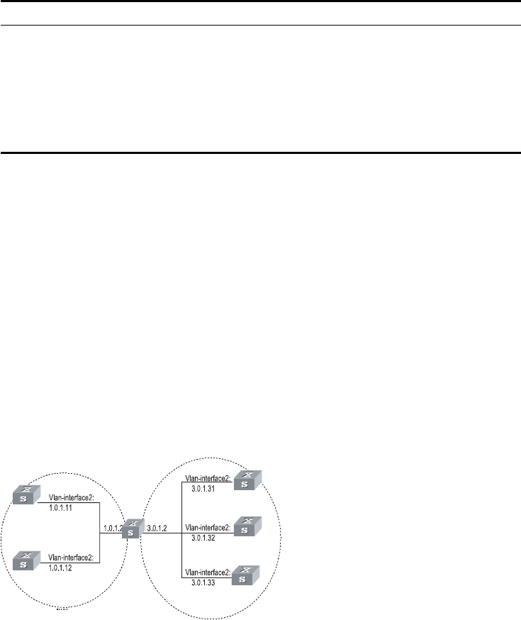
NTP 341
Displaying and Debugging NTP
After completing the previous configurations, you can use the display command
to show how NTP runs and verify the configurations according to the outputs. You
can use the debugging command, in user view, to debug NTP. See Table 78 for
the details of these commands.
NTP Configuration
Examples
NTP configuration examples are shown in the following:
■Configuring NTP Servers
■Configuring NTP Peers
■Configuring NTP Broadcast Mode
■Configuring NTP Multicast Mode
■Configuring Authentication-Enabled NTP Server Mode
Configuring NTP Servers
On SW88001, set the local clock as the NTP master clock at stratum 2. On
SW88002, configure SW88001 as the time server in server mode and set the local
equipment as in client mode.
Figure 8 Typical NTP Configuration Networking Diagram
Configure the Switch SW88001:
1Enter system view.
<SW88001> system-view
2Set the local clock as the NTP master clock at stratum 2.
[SW88001]ntp-service refclock-master 2
Table 78 Displaying and Debugging NTP
Operation Command
Display the status of NTP service display ntp-service status
Display the status of sessions maintained by
NTP service
display ntp-service sessions [ verbose ]
Display the brief information about every NTP
time server on the way from the local
equipment to the reference clock source.
display ntp-service trace
Debug NTP debugging ntp-service
SW88001
SW88002
SW88000
SW88003
SW88004
SW88005
342 CHAPTER 11: SYSTEM MANAGEMENT
Configure Switch SW88002:
1Enter system view.
<SW88002> system-view
2Set SW88001 as the NTP server.
[SW88002]ntp-service unicast-server 1.0.1.11
The above examples synchronized SW88002 by SW88001. Before the
synchronization, the SW88002 is shown in the following status:
[SW88002]display ntp-service status
clock status: unsynchronized
clock stratum: 16
reference clock ID: none
nominal frequency: 100.0000 Hz
actual frequency: 100.0000 Hz
clock precision: 2^17
clock offset: 0.0000 ms
root delay: 0.00 ms
root dispersion: 0.00 ms
peer dispersion: 0.00 ms
reference time: 00:00:00.000 UTC Jan 1 1900(00000000.00000000)
After the synchronization, SW88002 turns into the following status:
[SW88002]display ntp-service status
clock status: synchronized
clock stratum: 8
reference clock ID: LOCAL(0)
nominal frequency: 100.0000 Hz
actual frequency: 100.0000 Hz
clock precision: 2^17
clock offset: 0.0000 ms
root delay: 0.00 ms
root dispersion: 10.94 ms
NTP 343
peer dispersion: 10.00 ms
reference time: 20:54:25.156 UTC Mar 7 2002(C0325201.2811A112)
By this time, SW88002 has been synchronized by SW88001 and is at stratum 3,
higher than SW88001 by 1.
Display the sessions of SW88002 and you will see SW88002 has been connected
with SW88001.
[SW88002]display ntp-service sessions
source reference stra reach poll now offset delay
disper
********************************************************************
****** [12345]127.127.1.0 LOCAL(0) 7 377 64 57
0.0 0.0 1.0
[5]1.0.1.11 0.0.0.0 16 0 64 - 0.0
0.0 0.0
[5]128.108.22.44 0.0.0.0 16 0 64 - 0.0
0.0 0.0
note: 1 source(master),2 source(peer),3 selected,4 candidate,5
configured
Configuring NTP Peers
On SW88003, set local clock as the NTP master clock at stratum 2. On SW88002,
configure SW88001 as the time server in server mode and set the local equipment
as in client mode. At the same time, SW88005 sets SW88004 as its peer. See
Figure 3-3.
Configure Switch SW88003:
1Enter system view.
<SW88003> system-view
2Set the local clock as the NTP master clock at stratum 2.
[SW88003]ntp-service refclock-master 2
Configure Switch SW88004:
1Enter system view.
<SW88004> system-view
2Set SW88001 as the NTP server at stratum 3 after synchronization.
[SW88004]ntp-service unicast-server 3.0.1.31
Configure Switch SW88005: (SW88004 has been synchronized by SW88003)
1Enter system view.
<SW88005> system-view
2Set the local clock as the NTP master clock at stratum 1.
344 CHAPTER 11: SYSTEM MANAGEMENT
[SW88005]ntp-service refclock-master 1
3After performing local synchronization, set SW88004 as a peer.
[SW88005]ntp-service unicast-peer 3.0.1.32
The above examples configure SW88004 and SW88005 as peers and configure
SW88005 as in active peer mode and SW88004 in passive peer mode. Since
SW88005 is at stratum 1 and SW88004 is at stratum 3, synchronize SW88004 by
SW88005.
After synchronization, SW88004 status is shown as follows:
[SW88004]display ntp-service status
clock status: synchronized
clock stratum: 8
reference clock ID: LOCAL(0)
nominal frequency: 100.0000 Hz
actual frequency: 100.0000 Hz
clock precision: 2^17
clock offset: 0.0000 ms
root delay: 0.00 ms
root dispersion: 10.94 ms
peer dispersion: 10.00 ms
reference time: 20:54:25.156 UTC Mar 7 2002(C0325201.2811A112)
By this time, SW88004 has been synchronized by SW88005 and it is at stratum 2,
or higher than SW88005 by 1.
Display the sessions of SW88004 and you will see SW88004 has been connected
with SW88005.
[SW88004]display ntp-service sessions
source reference stra reach poll now offset delay
disper
********************************************************************
****** [12345]127.127.1.0 LOCAL(0) 7 377 64 57
0.0 0.0 1.0
[5]1.0.1.11 0.0.0.0 16 0 64 - 0.0
0.0 0.0
[5]128.108.22.44 0.0.0.0 16 0 64 - 0.0
0.0 0.0
NTP 345
note: 1 source(master),2 source(peer),3 selected,4 candidate,5
configured
Configuring NTP Broadcast Mode
On SW88003, set local clock as the NTP master clock at stratum 2, and configure
to broadcast packets from Vlan-interface2. Configure SW88004 and SW88001 to
listen to the broadcast from their Vlan-interface2. See Figure 1-2.
Configure Switch SW88003:
1Enter system view.
<SW88003> system-view
2Set the local clock as the NTP master clock at stratum 2.
[SW88003]ntp-service refclock-master 2
3Enter Vlan-interface2 view.
[SW88003]interface vlan-interface 2
4Set it as broadcast server.
[SW88003-Vlan-Interface2]ntp-service broadcast-server
Configure Switch SW88004:
1Enter system view.
<SW88004> system-view
2Enter Vlan-interface2 view.
[SW88004]interface vlan-interface 2
[SW88004-Vlan-Interface2]ntp-service broadcast-client
Configure Switch SW88001:
1Enter system view.
<SW88001> system-view
2Enter Vlan-interface2 view.
[SW88001]interface vlan-interface 2
[SW88001-Vlan-Interface2]ntp-service broadcast-client
The above examples configured SW88004 and SW88001 to listen to the
broadcast through Vlan-interface2, SW88003 to broadcast packets from
Vlan-interface2. Since SW88001 and SW88003 are not located on the same
segment, they cannot receive any broadcast packets from SW88003, while
SW88004 is synchronized by SW88003 after receiving its broadcast packet.
After the synchronization, you can find the state of SW88004 as follows:
[SW88004]display ntp-service status
clock status: synchronized
clock stratum: 8
reference clock ID: LOCAL(0)
nominal frequency: 100.0000 Hz
346 CHAPTER 11: SYSTEM MANAGEMENT
actual frequency: 100.0000 Hz
clock precision: 2^17
clock offset: 0.0000 ms
root delay: 0.00 ms
root dispersion: 10.94 ms
peer dispersion: 10.00 ms
reference time: 20:54:25.156 UTC Mar 7 2002(C0325201.2811A112)
By this time, SW88004 has been synchronized by SW88003 and it is at stratum 3,
higher than SW88003 by 1.
Display the status of SW88004 sessions and you will see SW88004 has been
connected to SW88003:
[SW88002]display ntp-service sessions
source reference stra reach poll now offset delay
disper
********************************************************************
****** [12345]127.127.1.0 LOCAL(0) 7 377 64 57
0.0 0.0 1.0
[5]1.0.1.11 0.0.0.0 16 0 64 - 0.0
0.0 0.0
[5]128.108.22.44 0.0.0.0 16 0 64 - 0.0
0.0 0.0
note: 1 source(master),2 source(peer),3 selected,4 candidate,5
configured
Configuring NTP Multicast Mode
SW88003 sets the local clock as the master clock at stratum 2, and multicast
packets from Vlan-interface2. Set SW88004 and SW88001 to receive multicast
messages from their respective Vlan-interface2. See Figure 1-2.
Configure Switch SW88003:
1Enter system view.
<SW88003> system-view
2# Set the local clock as a master NTP clock at stratum 2.
[SW88003]ntp-service refclock-master 2
3Enter Vlan-interface2 view.
[SW88003]interface vlan-interface 2
4Set it as a multicast server.
[SW88003-Vlan-Interface2]ntp-service multicast-server
NTP 347
Configure Switch SW88004:
1Enter system view.
<SW88004> system-view
2Enter Vlan-interface2 view.
[SW88004]interface vlan-interface 2
3Enable multicast client mode.
[SW88004-Vlan-Interface2]ntp-service multicast-client
Configure Switch SW88001:
1Enter system view.
<SW88001> system-view
2Enter Vlan-interface2 view.
[SW88001]interface vlan-interface 2
3Enable multicast client mode.
[SW88001-Vlan-Interface2]ntp-service multicast-client
The above examples configure SW88004 and SW88001 to receive multicast
messages from Vlan-interface2, SW88003 multicast messages from
Vlan-interface2. Since SW88001 and SW88003 are not located on the same
segments, SW88001 cannot receive the multicast packets from SW88003, while
SW88004 is synchronized by SW88003 after receiving the multicast packet.
Configuring Authentication-Enabled NTP Server Mode
SW88001 sets the local clock as the NTP master clock at stratum 2. SW88002 sets
SW88001 as its time server in server mode and itself in client mode and enables
authentication. See Figure 1-2.
Configure Switch SW88001:
1Enter system view.
<SW88001> system-view
2Set the local clock as the master NTP clock at stratum 2.
[SW88001]ntp-service refclcok-master 2
Configure Switch SW88002:
1Enter system view.
<SW88002> system-view
2Set SW88001 as time server.
[SW88002]ntp-service unicast-server 1.0.1.11
3Enable authentication.
[SW88002]ntp-service authentication enable
4Set the key.
[SW88002]ntp-service authentication-keyid 42 authentication-mode md5
aNiceKey
5Set the key as reliable.
348 CHAPTER 11: SYSTEM MANAGEMENT
[SW88002]ntp-service reliable authentication-keyid 42
The above examples synchronized SW88002 by SW88001. Since SW88001 has
not been enabled authentication, it cannot synchronize SW88002.
Perform the following additional configurations on SW88001:
1Enable authentication.
[SW88001]ntp-service authentication enable
2Set the key.
[SW88001]ntp-service authentication-keyid 42 authentication-mode md5
aNiceKey
3Configure the key as reliable.
[SW88001]ntp-service reliable authentication-keyid 42
