3Com 3CRWEASY96A Garg User Manual To The A4d8c1ce A1ca 4560 939f 4e55a7e111c3
User Manual: 3Com 3CRWEASY96A to the manual
Open the PDF directly: View PDF ![]() .
.
Page Count: 50
- Introduction
- Installing the Outdoor Bridge
- Configuring the Building-to-Building Bridge
- Using the 3Com Wireless Device Manager
- Saving Configuration Changes
- Changing System Properties
- Setting IP Network Properties
- Setting up Protocol and Port Filtering
- Setting Wireless Network Properties
- Setting Advanced Performance Properties
- Setting up an Ad Hoc Network
- Optimizing an Ad Hoc Installation
- Setting up an Access Point Infrastructure Network
- Changing Security Settings
- Resetting the Bridge
- Restoring a Bridge to Factory Defaults
- Upgrading the System
- Changing the Administration Password
- Backing up a Configuration
- Restoring a Configuration
- Viewing the Client List
- Viewing Connection Status
- Viewing the System Summary
- Interoperating with Third-Party Equipment
- Troubleshooting
- Technical Support
- Regulatory Compliance Information
- Index

3Com Corporation
5500 Great America
Parkway
Santa Clara, California
95052-8145
Copyright © 2003 3Com Corporation. All rights reserved. No part of this documentation may be
reproduced in any form or by any means or used to make any derivative work (such as
translation, transformation, or adaptation) without written permission from 3Com Corporation.
3Com Corporation reserves the right to revise this documentation and to make changes in
content from time to time without obligation on the part of 3Com Corporation to provide
notification of such revision or change.
3Com Corporation provides this documentation without warranty, term, or condition of any
kind, either implied or expressed, including, but not limited to, the implied warranties, terms or
conditions of merchantability, satisfactory quality, and fitness for a particular purpose. 3Com
may make improvements or changes in the product(s) and/or the program(s) described in this
documentation at any time.
If there is any software on removable media described in this documentation, it is furnished
under a license agreement included with the product as a separate document, in the hard copy
documentation, or on the removable media in a directory file named LICENSE.TXT
or!LICENSE.TXT. If you are unable to locate a copy, please contact 3Com and a copy will be
provided to you.
UNITED STATES GOVERNMENT LEGEND
If you are a United States government agency, then this documentation and the software
described herein are provided to you subject to the following:
All technical data and computer software are commercial in nature and developed solely at
private expense. Software is delivered as “Commercial Computer Software” as defined in DFARS
252.227-7014 (June 1995) or as a “commercial item” as defined in FAR 2.101(a) and as such is
provided with only such rights as are provided in 3Com’s standard commercial license for the
Software. Technical data is provided with limited rights only as provided in DFAR 252.227-7015
(Nov 1995) or FAR 52.227-14 (June 1987), whichever is applicable. You agree not to remove or
deface any portion of any legend provided on any licensed program or documentation
contained in, or delivered to you in conjunction with, this User Guide.
Unless otherwise indicated, 3Com registered trademarks are registered in the United States and
may or may not be registered in other countries.
3Com, the 3Com logo, and SuperStack are registered trademarks of 3Com Corporation. Wi-Fi is
a trademark of the Wireless Ethernet Compatibility Alliance.
All other company and product names may be trademarks of the respective companies with
which they are associated.
EXPORT RESTRICTIONS:
This product contains Encryption and may require US and/or Local
Government authorization prior to export or import to another country.

Contents
1
Introduction
Basic Network Topologies 7
Point-to-Point 7
Point-to-Multipoint 8
Basic Operating Modes 9
2
Installing the Outdoor Bridge
Installation Requirements 10
Power Requirements 10
Administration Requirements 11
Installation Guidelines 11
Proper Grounding 11
Alignment 12
Polarization 12
Restrictions on Antenna Use 12
Safety Information 13
Mounting the Bridge to a Mast 14
Connecting the Bridge to the LAN 15
Using the Power Supply 15
Using a Power-Over-Ethernet LAN Port 15
Installing Software Utilities 16
Establishing Wireless Association 17
3
Configuring the Building-to-Building Bridge
Using the 3Com Wireless Device Manager 18
Launching a Wireless Device Configuration 18
Using the Pre-IP Configuration Wizard 20
Using the RSSI Monitor 20
Saving Configuration Changes 21
Changing System Properties 21
Setting IP Network Properties 22

Setting up Protocol and Port Filtering 23
Setting Wireless Network Properties 24
Setting Advanced Performance Properties 26
Setting up an Ad Hoc Network 28
Optimizing an Ad Hoc Installation 29
Setting up an Access Point Infrastructure Network 30
Changing Security Settings 31
No Security (Open System) 32
40-bit Shared Key (Wi-Fi) 32
128-bit Shared Key 33
128-bit Dynamic Security Link 33
Setting up the Wireless Network Login 33
Resetting the Bridge 33
Restoring a Bridge to Factory Defaults 34
Upgrading the System 34
Changing the Administration Password 35
Backing up a Configuration 35
Restoring a Configuration 36
Viewing the Client List 36
Resetting Statistics Listings 37
Clearing the Client List 37
Viewing Connection Status 37
Viewing the System Summary 37
Interoperating with Third-Party Equipment 37
4
Troubleshooting
Diagnosing Problems 38
Disconnecting the Bridge 40
Uninstalling Software and Documentation 40
Upgrading Bridge Firmware 40
A
Technical Support
Online Technical Services 41
Support from Your Network Supplier 42
Support from 3Com 42
Returning Products for Repair 43


7
1
I
NTRODUCTION
The 3Com® Wireless LAN Outdoor Bridge Solution is a comprehensive
building-to-building outdoor wireless LAN kit that reduces the need to evaluate,
purchase and assemble separate components. One convenient package includes
everything you need to offer an easy-to-manage building-to-building wireless
LAN. The package features a 3Com Wireless LAN Building-to-Building Bridge with
integrated antenna and power-over-Ethernet cable in a durable,
weatherproof enclosure.
This all-in-one wireless LAN solution delivers three to four times the bandwidth of
T1 links, with significantly lower operational costs. The wireless bridge lets you
connect cross-campus buildings, or portable or temporary classrooms, at
distances up to 16 kilometers (10 miles), where local regulations allow. The
building-to-building bridge interoperates seamlessly with other Wi-Fi certified
access points in large multi-vendor environments.
B
ASIC
N
ETWORK
T
OPOLOGIES
The 3Com bridge can be used in two types of wireless network topologies:
■
Point-to-point
■
Point-to-multipoint
P
OINT
-
TO
-P
OINT
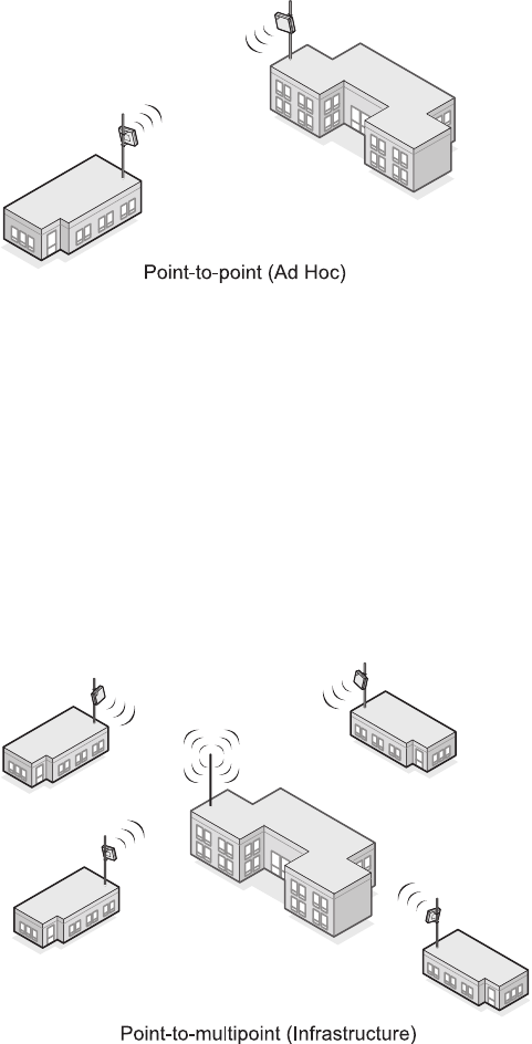
Point-to-point topology is the simplest way to use the 3Com bridge, and it offers
the highest performance level. Two 3Com outdoor bridges form a direct wireless
8
association between the wired LANs in two remote buildings. See the following
diagram of the point-to-point topology.
P
OINT
-
TO
-M
ULTIPOINT
Point-to-multipoint topology allows communication among three or more
buildings. In the central building, an access point equipped with an
omnidirectional antenna provides wireless association among the wired LANs in
the other buildings where 3Com outdoor bridges are installed.
If a 3Com 11 Mbps Wireless LAN Access Point 8000 is used (with an 8dBi
omnidirectional antenna) this topology can connect wired LANs over distances up
to 10 kilometers (6 miles). If an access point from another Wi-Fi compliant
manufacturer is used, the range depends on that manufacturer’s device
limitations.
9
B
ASIC
O
PERATING
M
ODES
Two operating modes relate to the basic WLAN topologies:
■
Ad hoc mode is the basis for point-to-point topology. Operating in ad hoc
mode, two outdoor bridges can associate without an access point, allowing
the LANs to which they are connected to communicate.
■
Access Point (Infrastructure) mode is the basis for point-to-multipoint
topology. Operating in access point mode, multiple 3Com outdoor bridges act
as clients to an Access Point 8000 or a Wi-Fi compliant access point from
another manufacturer.

10
2
I
NSTALLING
THE
O
UTDOOR
B
RIDGE
This equipment must be installed in compliance with local and national building
codes, regulatory restrictions, and FCC rules. For the safety of people and
equipment, only professional network personnel should install the bridge, cables,
and antennas.
I
NSTALLATION
R
EQUIREMENTS
The following items are required for installation:
■
For a point-to point configuration, two 3Com outdoor bridges.
■
For a point-to-multipoint configuration, one 3Com 11Mbps Wireless LAN
Access Point 8000 (or other Wi-Fi compliant access point) with an
omnidirectional antenna for one building, and one 3Com outdoor bridge for
each other building.
■
Mounting hardware (supplied with each bridge).
■
Properly grounded outdoor mast or wall mount.
■
Lightning arrestor properly grounded at each building in the topology.
■
Outdoor rated category 5 Ethernet cable (3Com part number
3CWE487 recommended).
P
OWER
R
EQUIREMENTS
The bridge complies with the IEEE 802.3af power-over-Ethernet standard. It
receives power over outdoor rated Ethernet cable (3Com part number 3CWE487
recommended). Installation requires the use of either the 3Com power supply
provided or IEEE 802.3af compliant power supply equipment (output power rated
48 V dc @ 200 mA minimum). Such equipment must b
e
safety certified according
to UL, CSA, IEC or other applicable national or international safety requirements
CAUTION
: Before installing, see the important warnings and cautions in “Safety
Information” on page 13.

11
for the country of use. All references to the power supply in this document refer
to equipment that meets these requirements.
Because the power supply plug is the only means of disconnecting the bridge
from power, make sure the power outlet is accessible.
See “Using the Power Supply” on page 15 and “Using a Power-Over-Ethernet
LAN Port” on page 15.
A
DMINISTRATION
R
EQUIREMENTS
To use the administration tool, which helps you select 3Com wireless LAN devices
and launch their configuration management systems, you need a computer
running one of the following operating systems and one of the
following browsers:
I
NSTALLATION
G
UIDELINES
The 3Com outdoor bridge is housed in a durable, waterproof enclosure and is
specifically designed for outdoor use in most climates. Optimal performance can
be maintained at outdoor temperature ranges from -20˚ C to 50˚C (-4˚F to 122˚F).
It is extremely important to avoid mounting the bridge in any area where it could
be vulnerable to extreme or hazardous conditions of any kind. Nor should the unit
be mounted flush with the roof of a building.
P
ROPER
G
ROUNDING
To ensure the physical safety of anyone near the bridge and to prevent damage to
the unit, follow the building codes for antenna installations in your area. Make
certain that bridges and masts are appropriately grounded to prevent injury and
Note for use of the 3Com power supply (part number 61-0107-000) in Norway:
This product is also designed for use on an IT power system with phase-to-phase
voltage of 230 V.
Operating Systems
Windows XP
Windows 2000
Windows NT 4.0
Windows Me
Windows 98
Browsers
Netscape 6.0 or later
Internet Explorer 5.0 or later
12
minimize damage from lightning strikes. A lightning arrestor, properly grounded
and installed at each building in the topology, will protect networking equipment
in the building, as well as the people working there, from lightning-induced
surges that travel on Ethernet cables.
A
LIGNMENT
Position bridges so that they are aimed at each other wherever possible. While
maintaining a direct line of sight between antennas helps to ensure a strong
signal, it is not strictly necessary, nor is it always possible. Conditions such as long
distances, mountainous regions, and architectural barriers could make a direct
line of sight nearly impossible to achieve.
In a campus setting, where buildings are short distances apart, and especially in a
point-to-point configuration, align each unit to point at the antenna with which it
will communicate. If you place two units at different heights, tilt them up or
down toward each other for optimal signal strength.
P
OLARIZATION
Polarization is a physical phenomenon of radio signal propagation. In general, any
two antennas that are to communicate with each other must be set for the same
horizontal or vertical polarization. If polarization on both antennas does not
match—a situation called
cross-polarization
—the link will either work poorly or
not at all. Follow these polarization guidelines:
■
Vertical polarization is preferred for point-to-multipoint configuration.
■
For point-to-multipoint configurations, the omnidirectional antenna
connected to the access point should be vertically aligned in relation to
the ground.
■
Unidirectional antennas that link with omnidirectional antennas should always
be oriented for vertical polarization.
R
ESTRICTIONS
ON
A
NTENNA
U
SE
The following restrictions apply to the use of the bridge’s 18 dBi antenna:
■FCC regulations require that in the United States, use of channels 12 and 13 in
conjunction with an 18 dBi antenna is allowed only at very reduced power,
which the 3Com unit sets automatically.
■The highest allowable power level is set automatically when the country
selection is made from the pulldown menu in the configuration tool.
■To work properly with 18 dBi antennas, bridges must be separated by at least
61 Meters (200 Feet).

13
SAFETY INFORMATION
WARNING: Do not install the bridge near overhead power lines, electric light or
power circuits, or where it can come into contact with such circuits. Provide ten
feet or more clearance between the bridge and such power lines or circuits. Do
not install the bridge flush with the rooftop or wall. When installing the bridge, do
not come into contact with such circuits, which can cause serious injury or death.
Follow local and national codes for proper installation and grounding of antennas.
WARNING: To comply with FCC radio frequency (RF) exposure limits, antennas
should be located at least two meters (six feet) or more from the bodies of
all persons.
WARNING: Do not install the bridge or connect and disconnect cables during
periods of lightning activity.
WARNING: To avoid possible injury or damage to equipment, you must use either
the provided power supply or IEEE 802.3af compliant power supply equipment
that is safety certified according to UL, CSA, IEC, or other applicable national or
international safety requirements for the country of use. All references to power
supply in this document refer to equipment meeting these requirements.
WARNING: It is the responsibility of the installer to ensure that the
Power-over-Ethernet (POE) power supply is properly connected. Connection to any
other device, such as a standard Ethernet card or another POE supply, may result
in permanent damage to equipment, electric shock, or fire. Refer to the
installation instructions for proper installation.
WARNING: The 3Com power supply (part number 61-0107-000) input relies on a
16A rated building fuse or circuit protector for short circuit protection of the line
to neutral conductors.
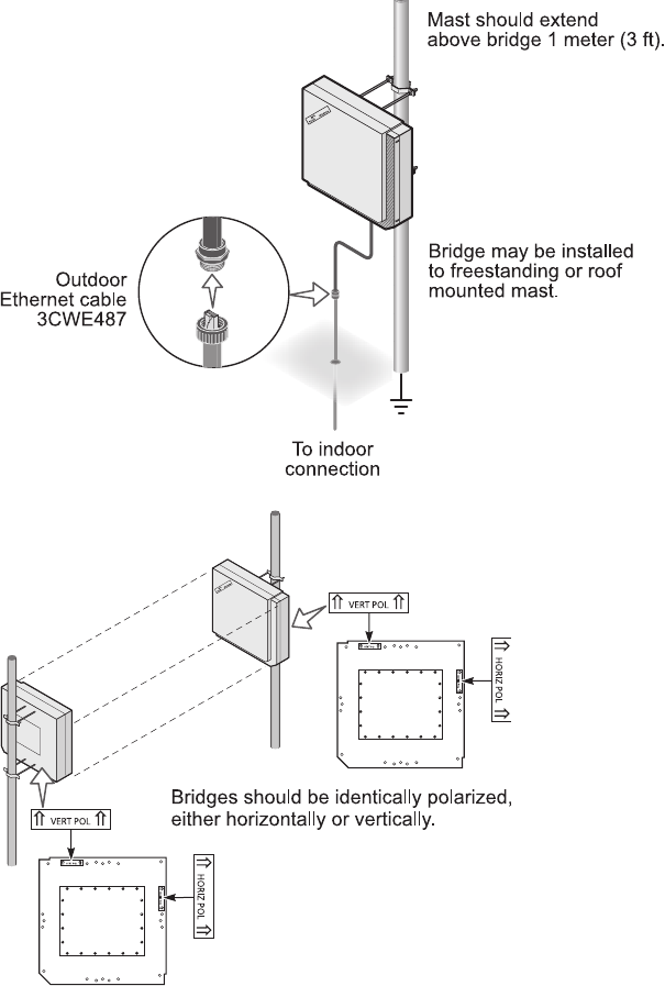
CAUTION: A lightning arrestor will not prevent damage from direct lightning
strikes. It is extremely important to ensure that the bridge is installed at least 1
meter (3 feet) below the top of the grounded pole or mast.
CAUTION: If you supply your own Ethernet cable for connecting power, be sure
that it is outdoor rated category 5 straight-through (8-wire) cable that has not
been altered in any way (3Com part number 3CWE487 recommended). Use of
nonstandard cable could damage the bridge.
CAUTION: Minimize damage from direct lightning strikes by mounting the bridge
at least 1 Meter (3 feet) below the top of the mast.
14
MOUNTING THE BRIDGE TO A MAST
The bridge can be placed in any suitable outdoor location (see “Installation
Guidelines” on page 11). Refer to the adjustable mount instruction sheet that
comes with the bridge mounting hardware, and the illustrations below:
Make sure that all bridges
are properly oriented for
polarization as described
in “Polarization” on
page 12. Use the
polarization indicators on
the antenna panel to
guide orientation. VERT
POL indicates vertical
polarization and HORIZ
POL indicates horizontal
polarization.
15
CONNECTING THE BRIDGE TO THE LAN
You can connect to the LAN either through the 3Com power supply or through
IEEE 802.3af power-over-Ethernet compliant equipment.
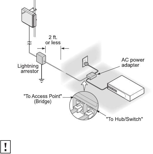
USING THE POWER SUPPLY
The power supply can be located indoors at any point between the bridge and
the LAN access port where an accessible power outlet exists.
Connect the cable coming from the bridge to the port labeled To Access Point on
the power supply.
Connect another Ethernet cable from the port labeled To Hub/Switch on the
power supply to an Ethernet LAN port, as shown.
USING A POWER-OVER-ETHERNET LAN PORT
If your LAN equipment complies with the IEEE 802.3af power-over-Ethernet
standard, you can connect the bridge directly to a LAN port. For example, the
CAUTION: To avoid damaging network equipment, make sure that the cables
are connected from bridge to power supply to LAN as shown and
described above.
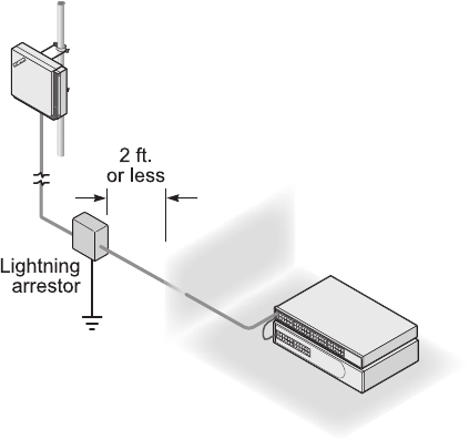
16
illustration shows the connection through a 3Com Ethernet Power Supply to a
3Com SuperStack® Switch.
INSTALLING SOFTWARE UTILITIES
The 3Com installation CD includes the Wireless Infrastructure Device Manager
tool, which helps you set up and administer the wireless components of your
network. It also contains documentation, including the help files for device
configuration screens.
To install the tool and documentation from the CD:
1Power up the computer and insert the 3Com CD in the CD-ROM drive.
2The setup menu should appear when the CD autostarts. If no menu appears,
you can run the startup program from the Windows Start menu:
Start/Run/d:setup.exe (where d: is the CD-ROM drive)
3From the menu, select Install the Tools and Documentation. This option
installls the 3Com Wireless Infrastructure Device Manager (WIDMAN) Tool,
which you can use to monitor bridges and select devices for administrative
changes. It also installs the User Guide in HTML and PDF formats.
4Follow the instructions on the screen.
17
ESTABLISHING WIRELESS ASSOCIATION
After the bridge and software utilities are installed, you can configure the bridge
as follows:
■Launch the bridge configuration. (See “Configuring the Building-to-Building
Bridge” on page 18 for details on how to launch the configuration and
make changes.)
■For a point-to-point association between two bridges, see “Setting up an Ad
Hoc Network” on page 28 and “Optimizing an Ad Hoc Installation” on
page 29.
■For a point-to-multipoint association between an access point and one or
more bridges, see “Setting up an Access Point Infrastructure Network” on
page 30.

18
3CONFIGURING THE
BUILDING-TO-BUILDING BRIDGE
If the configuration that was set at the factory does not meet your network
requirements, or if you want to customize the settings, you can configure the
bridge through your Web browser.
The 3Com Wireless Infrastructure Device Manager helps you locate 3Com
wireless LAN devices on the network, select a device and view its properties, and
launch the device’s configuration in your Web browser. To configure a bridge, the
device manager must be installed on a computer that has an Ethernet adapter
and is running a supported Windows operating system and Web browser.
USING THE 3COM WIRELESS DEVICE MANAGER
After the 3Com Wireless Device Manager is installed, ensure that the device to be
configured is either wired to the network, associating with the wireless network,
or connected directly to the computer, and connected to power. If more than one
device using the factory default name is connected, make a note of the MAC
address of the device you want to select so that you can identify it in the
device manager.
LAUNCHING A WIRELESS DEVICE CONFIGURATION
If you do not have a DHCP server on your network, it can take up to one minute
for a device to become discoverable after it has been powered up.
1To launch the 3Com Device Manager, select Start /Programs /3Com
Wireless/Wireless Infrastructure Device Manager.
If you have more than one network adapter installed on your computer, you
may be prompted to choose a network adapter. Choose the appropriate
adapter and click OK.
The Wireless Network Tree appears in the 3Com Wireless Infrastructure
Device Manager window. The tree lists all WLAN service areas on the network
and expands to show the 3Com wireless LAN devices that are associated to
each service area. Devices in a different subnet than your computer are

19
identified with exclamation points (!). You can refresh this display by clicking
Refresh. You should refresh the display, for example, after you change a
device IP address.
2In the Wireless Network Tree, select the device you want to configure.
If more than one wireless LAN device appears in the tree and you are not sure
that you have selected the right one, click Properties and check the MAC
address to verify that it is the one you want.
3Click Configure.
■If the selected device is on the same subnet as your computer, the
Configuration Management System main page appears in your Web
browser. (If a password is set on the device, enter it when prompted.)
■If the selected device is on a different subnet, the Pre-IP Configuration
Wizard is activated automatically. This wizard lets you configure the IP
settings for the selected wireless device. It proposes IP address and subnet
mask settings derived from your computer’s settings, so the selected device
will then reside on the same subnet as your computer. You can accept the
suggested settings or change them as required. For more information, see
“Using the Pre-IP Configuration Wizard” on page 20.
The next window prompts for an administrative password to allow the new IP
address to be set. When the units are shipped from the factory, there is no
administration password and you should leave the password field blank. If an
administration password has been set for the device, enter the password and
click Next. The 3Com Web Configuration Management System main screen
appears in your Web browser.
The following table describes the functions of the buttons in the 3Com Wireless
Infrastructure Device Manager window.
Button Description
Properties Displays the following properties of the selected device: Device Name,
Device Type, Wireless LAN Service Area (ESSID), IP Address, Subnet Mask,
and MAC Address.
Configure Launches the Configuration Management System for the selected device. If
the selected device is on a different subnet, you are prompted to assign an
address on the same subnet as your computer.
Refresh Scans the network and displays the connected 3Com 11 Mbps Wireless
LAN devices.
Choose NIC If your computer has more than one network interface card installed,
allows you to choose which card you want to use.
Close Closes the device manager window and ends the session.
Help Launches the device manager help page in your browser.
20
USING THE PRE-IP CONFIGURATION WIZARD
You can only configure devices that are on the same subnet as your computer. To
configure a device on a different subnet, you must first assign it an IP address on
the same subnet as your computer. After you launch the configuration, you can
change settings as usual. Just before you finish, you must change the device IP
address back to its original setting.
Follow this procedure:
1In the Wireless Infrastructure Device Pre-IP Configuration window, accept the
suggested settings or change them as required. You can assign a static IP
address or specify that the device obtain its IP address from a DHCP server.
2The next window prompts for an administrative password. When the units
are shipped from the factory, there is no administration password and you
should leave the password field blank. If an administration password has
been set for the device, enter the password and click Next.
The Configuration Management System main page appears in your
Web browser.
USING THE RSSI MONITOR
The device manager can display a dynamic graphical representation of a device’s
received signal strength indication (RSSI). By monitoring the RSSI while making
antenna adjustments, you can ensure optimal device placement and orientation.
To monitor signal strength, the devices must be set to the same BSSID and RSSI
broadcasting must be enabled.
The following procedure uses the device manager RSSI Monitor to monitor the
signal strength of two 3Com bridges:
1In the device manager window, launch the first bridge configuration and
configure for ad hoc mode.
Enable RSSI broadcasting as follows:
aIn the main menu under System Configuration, click Wireless Network.
bIn the Wireless Network page, click the link to go to advanced wireless
network configuration.
cIn the Advanced Wireless Network page, click the Broadcast RSSI On radio
button, and click Save.
dNote the device BSSID.
In the main configuration menu under System Status, click
Connection Status. The status window shows the BSSID.
21
2Return to the device manager and repeat step 1 for the second bridge. Make
sure that both bridges are using the same BSSID.
If the bridges are not using the same BSSID, specify the BSSID on both bridges
as follows:
aIn the Wireless Network page, select the following Network Mode: Ad-hoc
(Peer-to-Peer) Specify.
bEnter the BSSID in the spaces provided.
cClick Save.
3After you have enabled RSSI broadcasting on both bridges and verified that
they are using the same BSSID, return to the device manager, select the first
bridge, and click Properties.
4In the device properties window, click RSSI Monitor.
The RSSI Monitor window shows a graphical representation of bridge signal
strength. A value of 30 indicates good strength; a value of 40 or above is very
good. By adjusting the antenna position and orientation, you can improve the
signal strength.
SAVING CONFIGURATION CHANGES
Most pages in the configuration have two buttons: Save and Clear. After making
changes on a page, you must click Save to store the modifications before moving
to a new page. If you make a mistake, click Clear before saving to restore the original
page settings.
To reduce the possibility of losing wireless association with an access point while
you are configuring, security settings are stored when you click Save in the
security pages, but they do not take effect until you click Save in the Wireless
Network page. First configure security settings. Then go to the Wireless
Network page and configure wireless network settings, including the Wireless
LAN Service Area. The security settings take effect after you click Save in the
Wireless Network page.
CHANGING SYSTEM PROPERTIES
Under System Configuration, click System Properties. The System Properties page
displays the properties of the selected device. You can modify properties by
entering values in the fields and clicking the radio buttons. When you are
finished, click Save. The following table describes the properties and default
values.

22
SETTING IP NETWORK PROPERTIES
Under System Configuration, click IP Network. The IP Network Properties page
appears, where you can change the following settings. When you are finished,
click Save.
■IP Network Setting—This setting allows you to change the device IP address.
To let the device get an IP address automatically from a DHCP server, click
Obtain an IP address automatically.
Property Description Default Value
Device Name This name appears in the System Summary window. You
can change the default name to one of your choice.
3Com Bldg-to-Bldg Bridge
Device Location Optionally, you can enter a location to identify where the
device is installed. (For example, Building 4, Cubicle 3.)
None
Help File Location ■Web Server: Help files are located on the network at
the specified Help File Path.
■Local Drive: Help files are located on the local
computer at the specified Help File Path.
Local Drive
Help File Path The location of the Configuration Management System
help files on the web server or on the local drive.
If you want to have access to help when you click the ? in
the configuration pages, you must install the help from
the 3Com CD. By default, help is installed on the local
drive when you install the administration tool. If you
install the help in a different location on the local drive or
on a web server, you must set the Help File Path to the
correct location.
C:/Program
Files/3Com/3Com Wireless
Infrastructure Device
Manager/ManagementHelp/
B2B
Secure Web Server
Connection
Controls whether Secure Socket Layer (SSL) technology is
used to encrypt information between the computer and
the bridge during a configuration session. When this
option is turned on, data is protected during the
configuration session. When it is turned off, data could
be intercepted during the configuration session.
Changing this option causes the bridge to reset, which
disrupts the network association temporarily, but does
not affect bridge configuration settings that have already
been saved. To ensure that changes to security settings
are retained, either change this option before changing
security settings, or click Save in the Wireless Network
page after changing security settings and before
changing this option.
Off
23
To specify an IP address, click Specify an IP address, enter the IP address
parameters in the spaces provided.
After you change the IP address and click Save, you cannot continue to
configure the device using the old IP address. To continue configuring this
device after making this change, you must do the following:
aClose your browser.
bReturn to the 3Com Wireless Infrastructure Device Manager and
click Refresh.
cSelect the device and click Configure to start a new configuration session.
■IP Address, Subnet Mask, Gateway IP Address—Parameters for use when
you click Specify an IP address. Enter the parameters in the spaces provided.
SETTING UP PROTOCOL AND PORT FILTERING
Protocol filtering allows you to control the types of protocols that the bridge is
authorized to transmit and receive. The default setting allows the following
protocols to be transmitted and received:
■IPX
■NetBEUI
■UDP/IP
■TCP/IP
To set up a list of authorized protocols:
1Under System Configuration, click Protocol Filtering.
2In the Protocol Filtering page, click the Allow radio buttons next to the
protocols that you want to authorize. Click the Block radio buttons next to
the protocols that you want to disable.
3Click Save.
If UDP/IP or TCP/IP protocols are authorized, you can set up port filtering, which
allows you to control the protocol ports that are authorized to transport packets
through the bridge. The default setting allows all protocol ports to
transport packets.
The bridge allows you to filter up to 100 protocol port numbers. Valid protocol
port numbers range from 1 to 65535.

24
To set up protocol port filtering:
1Under System Configuration, click Protocol Filtering.
2In the Protocol Filtering page, click the Allow radio button next to the UDP/IP
or TCP/IP protocol (or click both buttons).
3Select the Port Filtering Mode:
Allow—If you want to block most protocol ports and allow a small number
of others, use the Allow mode. Click the Allow radio button.
Block—If you want to allow most protocol ports and block a small number of
others, use the Block mode. Click the Block radio button.
4Enter a protocol port number in the space provided and click Save.
Repeat this step for all the protocol port numbers you want to allow or block.
To view the list of protocol ports or delete protocol ports from the list:
1Click the link to view the protocol port list.
2In the next page, click the check boxes next to the protocol port numbers and
click Delete. (You may click Reset to clear all check boxes before
clicking Delete.)
SETTING WIRELESS NETWORK PROPERTIES
Under System Configuration, click Wireless Network Properties. The Wireless
Network Properties page appears, where you can configure the items listed below
and get access to advanced performance settings. When you are finished,
click Save.
■Network Mode—Click Access Point (Infrastructure) to associate with an
access point. Click Ad-hoc (Peer-to-Peer) to associate in ad hoc mode. Click
Ad-hoc (Peer-to-Peer) Specify if you want to specify the bridge’s basic service
set identification (BSSID).
■BSSID—When the network mode is Ad-hoc (Peer-to-Peer) Specify, you can
specify the BSSID. Enter the BSSID in the spaces provided.
■Wireless LAN Service Area—This is the device ESSID. The default WLAN
service area name is 3Com. You can use the default, enter a WLAN service
area, or select one from the list
Saving wireless network properties also causes security settings to take effect.
After making changes to security settings, you must click Save in the Wireless
Network Properties page to activate the security settings.

25
To maintain wireless association, the WLAN service area on a bridge and the
device with which it is associated must match exactly. Therefore, if the bridge
is set to specify the WLAN service area and you change the other device’s
WLAN service area, make sure to change the bridge WLAN service area also.
■Access Point Privacy Mode—This mode only applies when the network
mode is Access Point (Infrastructure) and should only be used when access
points are set with privacy enabled. (On 3Com access points, privacy is
enabled when the Broadcast WLAN Service Area Name (ESSID) mode is
disabled.) Click On to associate with access points set with privacy mode
enabled. Click Off to associate with access points set with privacy mode
disabled. When privacy mode is on, you must specify a Wireless LAN Service
Area, which must match the access point service area exactly.
■Channel Selection—When the network mode is Access Point (Infrastructure),
this option is set to Automatically select the best channel, and cannot be
changed. In this case, the bridge uses the channel that the access point
is using.
When the network mode is Ad-hoc (Peer-to-Peer) you can specify channel
selection as follows:
■Automatically select the best channel—When this option is enabled,
the bridge scans the primary channels. If the bridge is establishing a new
ad hoc network, it chooses the channel with the least number of packets.
If the bridge is joining an existing ad hoc network, it selects the channel
in use.
■Specify the channel to use—To establish the channel for an ad hoc
network, select this option on the first bridge and choose a channel from
the Channel list. On the second bridge, set the channel selection to match
the first bridge.
■Country Selection (Outdoor Bridge only)—Select the country from the
pull-down list. The highest allowable power level is automatically set.
■Antenna Selection (Indoor Bridge only)—When you select a valid country,
antenna, and cable combination, the highest allowable power level is set
automatically.
Select the country from the pull-down list.
Click the radio buttons next to the antenna and cable being used.
Antenna model 3CWE496 (18 dBi) is not available in some countries. In the
United States, use of channels 12 and 13 in conjunction with model
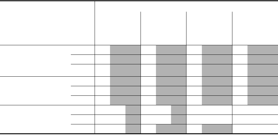
3CWE496 is not allowed. The following table summarizes these and other
FCC regulations require that in the United States, use of channels 12 and 13 in
conjunction with an 18 dBi antenna is allowed only at very reduced power,
which the 3Com bridge sets automatically.
26
restrictions. Y indicates the power level that is set automatically; N indicates
that a combination is not allowed.
SETTING ADVANCED PERFORMANCE PROPERTIES
Under System Configuration, click Wireless Network. On the Wireless Network
Properties page, click the link to go to advanced wireless network configuration.
The Advanced Wireless Network page appears, where you can change the
settings listed below. When you are finished, click Save.
■Network Traffic Accelerator—To increase performance, click On (Enhanced
performance). If you experience problems when equipment other than 3Com
11 Mbps Wireless LAN equipment is being used, click Off (Wi-Fi
Interoperable).
■Data Preamble—To increase performance, click Short (Enhanced
performance). When equipment that does not support short preamble is also
being used, click Long (Wi-Fi Interoperable).
■Flow Control—When there is a great deal of traffic on the wireless LAN, flow
control can prevent bridge input buffers from overflowing, thereby increasing
WLAN reliability. The bridge supports IEEE 802.3x asymmetric outgoing flow
control, allowing it to pause the transmission of data frames from a switch or
router that is operating in full-duplex mode and supports 10/100
Country
Cable
Length
Antenna:
4dBi 8 dBi 13 dBi 18 dBi
Power (dBm): Power (dBm): Power (dBm): Power (dBm):
18 13 7 18 13 7 18 13 7 18 13 7
Argentina, Brazil, Canada,
Colombia, India,
Malaysia, Mexico, New
Zealand, Peru, Taiwan
6 Y Y Y Y
20 Y Y Y Y
50 Y Y Y Y
United States 6 Y Y Y Y*
20 Y Y Y Y*
50 Y Y Y Y*
All Other Countries
(except China)†
6 NY NY NNYNNN
20 N Y N Y N N Y N N N
50 Y Y Y Y N N N
* Channels 12 and 13 not allowed when using 18 dBi antenna in the United States.
† Countries where transmit power is limited to 100 mW (20 dBm). In China, transmit power is limited to less than 10 mW.
27
auto-negotiation. To enable flow control, click On. To disable flow control,
click Off.
■Acknowledgement Delay—This setting determines the length of time the
bridge waits for an acknowledgement after transmitting packets. When the
delay time has passed, the bridge resends the packets. A longer
acknowledgement delay allows the bridge to associate with another wireless
device over a greater distance. Set the delay to match the distance between
the bridge and the wireless device with which it is associated. Click the radio
button next to the appropriate distance range.
■Client Limit—Allows you to specify the maximum number of clients that the
bridge allows to associate at the same time (from 1 to 1024). The default is
256 clients. In Access Point (Infrastructure) mode, set the Client Limit to match
the number of clients that the access point can support.
To ensure network reliability, follow these guidelines for configuring the
access point:
■Make sure that the access point can support more than the number of
clients that you expect to use the wireless LAN.
■The client list timeout setting should be as short as possible, but no less
than five minutes.
■Data Rates—These settings configure the data rates used for wireless
transmissions. By default, the bridge selects the best data rate for the
current connection.
You may not alter the settings for the 1Mbps and 2Mbps rates because these
rates must always be available to transmit certain types of wireless traffic.
The 5.5 Mbps and 11 Mbps data rates may either be Required or Optional.
When the data rate is set to Optional, the bridge determines if it is
appropriate to use that data rate or if the signal strength requires the use of a
lower data rate. If the data rate is set to Required, the bridge cannot
modulate to a lower data rate, and may lose connection with clients that
cannot support the higher data rate.
■Broadcast RSSI—This setting determines whether the device’s received signal
strength indication (RSSI) is broadcast. When RSSI broadcasting is enabled, you
can use the device manager or the Connection Status page to monitor the
signal strength. To enable RSSI broadcasting, click On. To disable RSSI
broadcasting, click Off.

28
SETTING UP AN AD HOC NETWORK
Operating in ad hoc mode, two bridges can establish a point-to-point association
without an access point, allowing two LANs to communicate.
1Install the first bridge.
2Use the 3Com Wireless Infrastructure Device Manager to select the first
bridge and launch its configuration management system.
3Configure security settings.
Security settings default to No Security (Open System). Optionally, you can set
shared key security as described in “40-bit Shared Key (Wi-Fi)” on page 32 or
“128-bit Shared Key” on page 33. (The 128-bit Dynamic Security Link option
is not available in ad hoc mode.)
4Under System Configuration, click Wireless Network.
(Wireless Network properties are described in “Setting Wireless Network
Properties” on page 24.)
5In the Wireless Network page:
aIn the Network Mode field, click Ad-hoc (Peer-to-Peer).
bSpecify the Wireless LAN Service Area.
cSpecify the Channel Selection.
To avoid the possibility of interference from other nearby wireless devices,
specify the channel to use.
dClick Save to save the wireless network settings and activate the
security settings.
eClick the link to go to advanced wireless network configuration.
6In the Advanced Wireless Network page, set options as described in “Setting
Advanced Performance Properties” on page 26.
7When you are finished, click Save.
8End the browser session.
9Install the second bridge and repeat the procedure. Make sure to configure
settings to match the first bridge exactly. When you are finished, click Save
and end the browser session.
To ensure correct operation, the settings on the two bridges must match exactly.
To avoid the possibility of losing wireless association while you are configuring, it
is recommended that you configure with a computer that is wired to the LAN.
To ensure a successful association, install and configure the bridges sequentially.
29
OPTIMIZING AN AD HOC INSTALLATION
You can optimize an ad hoc installation by adjusting antenna positions slightly to
improve the radio signal between bridges. The following tools help you to
optimize the installation:
■The device manager can display a dynamic graphical representation of the
bridge’s received signal strength indication (RSSI). By monitoring the RSSI while
making antenna adjustments, you can ensure optimal placement.
■The configuration Connection Status page displays the bridge’s basic service
set identification (BSSID) and a static RSSI value that you can refresh as
needed.
■The configuration Wireless Network page allows you to specify a BSSID,
if necessary.
To monitor signal strength, the bridges must be set to the same BSSID and RSSI
broadcasting must be enabled. In the factory default configuration, the BSSID is
generated automatically and RSSI broadcasting is disabled.
To use the device manager RSSI Monitor:
1Install the Wireless Infrastructure Device Manager (version 1.2.0.9 or later)
from the 3Com installation CD.
2Launch the device manager (Start /Programs /3Com Wireless/Wireless
Infrastructure Device Manager).
3In the device manager window, launch the first bridge configuration and
configure for ad hoc mode.
Enable RSSI broadcasting as follows:
aIn the main menu under System Configuration, click Wireless Network.
bIn the Wireless Network page, click the link to go to advanced wireless
network configuration.
cIn the Advanced Wireless Network page, click the Broadcast RSSI On radio
button, and click Save.
dNote the bridge BSSID.
In the main configuration menu under System Status, click
Connection Status. The status window shows the BSSID.
4Return to the device manager and repeat step 3 for the second bridge. Make
sure that both bridges are using the same BSSID.
If the bridges are not using the same BSSID, specify the BSSID on both bridges
as follows:
aIn the Wireless Network page, select the following Network Mode: Ad-hoc
(Peer-to-Peer) Specify.

30
bEnter the BSSID in the spaces provided.
cClick Save.
5After you have enabled RSSI broadcasting on both bridges and verified that
they are using the same BSSID, return to the device manager, select the first
bridge, and click Properties.
6In the device properties window, click RSSI Monitor.
The RSSI Monitor window shows a graphical representation of bridge signal
strength. A value of 30 indicates good strength; a value of 40 or above is very
good. By adjusting the antenna position, you can improve the signal strength.
You can also monitor signal strength through a status page in the configuration
as follows:
1Launch the bridge configuration.
2In the main configuration menu under System Status, click
Connection Status.
3The status window shows the RSSI value. Click Refresh to update the value
each time you adjust the antenna position.
SETTING UP AN ACCESS POINT INFRASTRUCTURE NETWORK
Operating in Access Point (Infrastructure) mode, one or more bridges can
establish a point-to-multipoint association with an access point, allowing the
LANs to which they are connected to communicate.
1Use an omnidirectional antenna atop the central building. Attach the antenna
to an access point inside the building. Install 3Com outdoor bridges or indoor
bridges with sector-panel directional antennas for the other buildings.
If a 3Com 11 Mbps Wireless LAN Access Point 8000 is used (with an 8 dBi
omnidirectional antenna), wired LANs can be connected over distances of up
to 10 kilometers (6 miles).
2Use the 3Com Wireless Infrastructure Device Manager to select the first
bridge and launch its configuration management system.
3Configure security settings. The bridge security settings must match those on
the access point.
Security settings default to No Security (Open System). Optionally, you can set
up the following types of security:
Configure the access point before configuring the bridges.

31
Shared key —See “40-bit Shared Key (Wi-Fi)” on page 32 or “128-bit
Shared Key” on page 33.
Password—If you are using a 3Com Access Point 8000, you can set up
password security as described in “128-bit Dynamic Security Link” on
page 33.
4Under System Configuration, click Wireless Network.
5In the Wireless Network page:
aIn the Network Mode field, click Access Point (Infrastructure).
bSpecify the Wireless LAN Service Area as described in “Setting Wireless
Network Properties” on page 24.
cClick Save. This saves the wireless network settings and activates the
security settings.
dClick the link to go to advanced wireless network configuration.
In the Advanced Wireless Network page, set the Client Limit option to match
the number of clients that the access point can support. (See Client Limit
under “Setting Advanced Performance Properties” on page 26.) To ensure
network reliability, follow these guidelines for configuring the access point:
Make sure that the access point can support more than the number of clients
that you expect to use the wireless LAN.
The client list timeout setting should be as short as possible, but no less than
five minutes.
6When you are finished, click Save.
7End the browser session.
8Repeat the procedure with the other bridges. Make sure you configure bridge
settings to match exactly. When you are finished, click Save and end the
browser session.
CHANGING SECURITY SETTINGS
Under System Configuration, click Security Settings. The Security Settings page
appears, where you can select the type of security to be used on the bridge. The
bridge can be configured to support one type of security at a time. You can
change the settings by clicking the radio buttons and entering values in the fields.
After saving security settings, you must go to the Wireless Network Properties
page and click Save to activate the security settings.

32
When you are finished, click Save. Then go to the Wireless Network Properties
page, set the Wireless LAN Service Area, and click Save. Security settings take
effect only after you click Save in the Wireless Network Properties page.
Although the bridge is allowed to associate with an access point set for a
different level of encryption, data authentication is not allowed. Therefore, data
cannot pass between the bridge and the access point unless their security settings
match exactly.
The following sections describe the security settings. To maintain wireless
association, the settings on clients and the access points they associate with (or
other members of an ad hoc network) must match exactly.
NO SECURITY (OPEN SYSTEM)
No encryption is used. The network communications could be intercepted by
unintended recipients.
40-BIT SHARED KEY (WI-FI)
This option encrypts the wireless transmissions to protect data, but still allows
communication among compatible wireless LAN clients and access points from
third-party manufacturers that are Wi-Fi certified.
This type of security requires you to set up encryption in one of the following
ways:
■String—For use only with other 3Com 11 Mbps wireless LAN devices, an
encryption string is a case-sensitive string of characters between 6 and 30
characters long. To enter the string, click Enter a string to generate shared
keys. Then type any combination of letters and numbers in the space provided
and click Save.
■Shared keys—Hexadecimal keys are sequences of hexadecimal digits
arranged into four keys. A hexadecimal digit may be a letter from A to F or a
number from 0 to 9. This type of encryption is compatible with equipment
from other manufacturers that use Wi-Fi certified 40-bit encryption. To enter
the keys, click Specify shared keys and which key to use. Then click the link to
specify and select the shared keys. In the shared keys window, enter all the
If you are configuring through a wireless association (not on the wired LAN), be
sure to configure security settings before changing the WLAN service area. If you
change the WLAN service area first, the bridge will lose association with one
access point before it is configured to associate with another.

33
keys in the provided spaces, then click a radio button in the Selected Key
column to specify which key to use and click Save.
128-BIT SHARED KEY
This option can be used with other 3Com 11 Mbps Wireless LAN devices and
with equipment from certain manufacturers that also support 128-bit shared key
encryption. It provides a higher level of security than the 40-bit Shared Key (Wi-Fi)
option and uses a more complicated type of encryption. This type of security
requires you to set up encryption using a string or shared keys as described above
in “40-bit Shared Key (Wi-Fi)” on page 32.
128-BIT DYNAMIC SECURITY LINK
This option can only be used with other 3Com 11 Mbps Wireless LAN devices
when the bridge is set to the Access Point (Infrastructure) network mode. It is the
highest level of security, requiring a user name and password to access the
wireless LAN. The user name and password set up on the bridge must match
those set up on the access point. Each network session creates a unique,
one-time encryption code.
If you choose this type of security, you must also set up a login as described in
“Setting up the Wireless Network Login” on page 33.
SETTING UP THE WIRELESS NETWORK LOGIN
If you configure a bridge for 128-bit Dynamic Security Link, you must also set up
a login user name and password, which must match a listing in the access point
user access list. In the Security Settings page, click 128-bit Dynamic Security Link.
Then click the link to modify the wireless network login. In the Wireless Network
Login page, enter a login name and password, and confirm the password in the
spaces provided. When you are finished, click Save.
RESETTING THE BRIDGE
If the bridge stops responding correctly, you can perform a reset, which disrupts
the network association temporarily, but does not affect bridge configuration
Make sure the access point does not require Windows user authentication. The bridge
cannot associate with access points that are set to Require Windows user
authentication, which requires clients to enter a user name and password every
time they associate with the network.
34
settings that have already been saved. To reset the bridge, under Tools, click Reset
Wireless Building-to-Building Bridge. In the next Web page, click Reset.
RESTORING A BRIDGE TO FACTORY DEFAULTS
You can restore bridge settings to the defaults that were set at the factory as
follows:
1Under Tools, click Restore Factory Defaults.
2Click Restore.
Manual Restore (indoor bridge only)—To restore the settings manually, insert
a pointed object (such as the end of a straightened paper clip) into the reset hole
on the front near the RJ-45 connector and hold for approximately 15 seconds.
If the bridge was using an IP address setting other than the default, restoring the
factory defaults will change the IP address. If you want to continue configuring
the bridge, do the following:
1Close your browser.
2Return to the 3Com Wireless Infrastructure Device Manager and click
Refresh.
3Select the device and click Configure to start a new configuration session.
UPGRADING THE SYSTEM
You can download firmware and configuration management system upgrades
from the 3Com Web site and install those upgrades on the bridge.
The upgrade procedure requires a Trivial File Transfer Protocol (TFTP) server. The
bridge acts as a TFTP client to receive the download.
To locate an upgrade file and download it to your computer:
1Log on to the 3Com Web site at http://www.3com.com.
2Navigate to the product support page for the 3Com Wireless LAN Outdoor
Bridge Solution to access the download files and instructions.
3Follow the instructions to download the file into a directory on your
computer.
4Copy or move the file to the TFTP server upload/download directory.
35
To install an upgrade:
1Use the 3Com Wireless Infrastructure Device Manager to select the device
and launch its configuration.
2Under Tools, click Upgrade System.
3Enter the name of the upgrade file that you downloaded earlier.
4Enter the IP address of the TFTP server where the upgrade file is located.
5Click Upgrade.
The upgrade file is copied from the TFTP server to the bridge. The bridge
restarts using the new upgrade.
CHANGING THE ADMINISTRATION PASSWORD
The first time you launch the Configuration Management System on the device or
after you reset a device to factory defaults, you are prompted to set an
administration password. Although a password is not required, 3Com
recommends that you set a password to protect against unauthorized access.
After you set the password, you must enter it each time you launch the
configuration for the device. A user name is not required.
Under Tools, click Change Administration Password. The Change Administration
Password page appears, where you can change the administration password for
the device. Enter the current password and new password in the spaces provided
and click Save.
BACKING UP A CONFIGURATION
As part of system maintenance, you should save and back up the configurations
of individual bridges in case you need to reload them in the future. The backup
saves all the parameters of the selected bridge in a file on your computer. The file
can be used later to restore the configuration on this or another bridge.
1Set the bridge parameters in the System Configuration pages.
2Under Tools, click Backup Wireless LAN Building-to-Building Bridge.
3In the next page, click Backup Now.
4Specify a name and location for the backup, and click OK.
36
RESTORING A CONFIGURATION
If you have stored a backup configuration on your computer, you can restore the
configuration as follows:
1Under Tools, click Restore Wireless LAN Building-to-Building Bridge.
2In the next page, click Browse and select the backup file to upload to the
bridge.
3Click Restore.
The configuration is restored and activated on the bridge. This operation may
cause the bridge to reboot.
If the bridge was using an IP address setting other than the backup, restoring the
configuration will change the IP address. If you want to continue configuring the
bridge, do the following:
1Close your browser.
2Return to the 3Com Wireless Infrastructure Device Manager and click
Refresh.
3Select the device and click Configure to start a new configuration session.
VIEWING THE CLIENT LIST
Under System Status, click Ethernet Client List. The Ethernet Client List page
appears, where you can view the following information:
■Ethernet Clients—Lists the client MAC addresses. The bridge supports up to
1024 specific clients. When the list reaches its limit, new clients replace
inactive clients (status Not Associated).
■# Transmitted Packets—The number of packets that the client has
transmitted.
■# Received Packets—The number of packets that the client has received.
■Association Status—One of the following:
Initializing—A new client is preparing to associate.
Associated—The client is active on the network.
Not Associated—The client is inactive.
The client list can be up to 10 pages long. Each page lists 100 clients. You can
search for a specific MAC address on the current page using your browser’s Find
function. To display another page, click a page number in the list at the top of the
current page.
37
RESETTING STATISTICS LISTINGS
In the Ethernet Client List page, click Reset Statistics to set the # Transmitted
Packets and # Received Packets listings back to zero.
CLEARING THE CLIENT LIST
You can clear the client list manually by clicking Reset Clients in the Ethernet
Client List page.
The bridge erases the client list. Thereafter, clients are added to the list
automatically when they next interact with the network.
VIEWING CONNECTION STATUS
Under System Status, click Connection Status to see information about the quality
of the wireless association.
Data rate values (1, 2, 5.5, or 11 Mbps) indicate the speed of data transfer. A data
rate of 0 indicates no data transfer.
Signal strength values in the RSSI field range from 0 (no signal) to 100 (excellent
signal quality). A signal strength of 30 is good; a value of 40 or greater is very
good.
Click Refresh to update the information.
VIEWING THE SYSTEM SUMMARY
Under System Status, click System Summary to see information about the bridge.
You can go to the configuration pages of items that can be configured by
clicking their names in the list.
Click Refresh to update the information.
INTEROPERATING WITH THIRD-PARTY EQUIPMENT
Because 3Com Wireless LAN equipment complies with IEEE 802.11b standards, it
can interoperate with third-party equipment that also complies with the
standards. However, some third party equipment may not support 3Com
enhanced performance features. You may need to turn off the Network Traffic
Accelerator and set the Data Preamble to long to support this equipment on
the network.
38
4TROUBLESHOOTING
DIAGNOSING PROBLEMS
If you have difficulty with a 3Com Wireless LAN building-to-building bridge, try
the solutions in the following table.
Symptom Solutions
Two bridges fail to communicate in ad
hoc mode.
■Adjust the positions of the antennas to improve reception.
■To ensure correct operation in ad hoc mode, the settings on the
two bridges must match exactly. Launch the bridge
configuration management system and make sure that the
Wireless LAN Service Area, channel selections, Data Preamble
setting, and security settings are the same on both bridges.
The bridge fails to associate with an
access point.
■Adjust the position of the antenna to improve reception.
■Launch the bridge configuration and make sure the security
settings, advanced performance settings, and access point
privacy mode settings on the bridge match those on the
access point.
■If the access point is from another manufacturer, try turning the
Network Traffic Accelerator off and setting the Data Preamble
to long.
■Using 128-bit Dynamic Security Link encryption, the bridge
cannot associate with access points that are set to Require
Windows user authentication, which requires clients to enter a
user name and password every time they associate with the
network. Make sure the access point does not require Windows
user authentication.
■If the bridge is using an 18 dBi antenna, the FCC restricts the
use of channels 12 and 13 to very reduced rates in the United
States. Access points set to automatically select the best channel
may occasionally select channel 12 or 13. To avoid
interruptions, it is recommended that you set the access point
to use a specific channel.
The 128-bit Dynamic Security Link setting
does not work in ad hoc mode.
128-bit Dynamic Security Link is not supported in ad hoc mode.
Use the 40-bit or 128-bit Shared Keys settings instead.

39
A bridge set for 128-bit Shared Key
encryption seems to communicate with
an access point set for 40-bit Shared Key
encryption or open system.
Although the bridge is allowed to associate with an access point
set for a different level of encryption, data authentication is not
allowed. Therefore, data cannot pass between the bridge and the
access point unless their settings match exactly.
The Wireless Network Tree does not
appear in the 3Com Wireless
Infrastructure Device Manager window.
Verify that you are using the correct network adapter. In the device
manager window, click Choose NIC. Select the network adapter for
the network you want to scan, and click OK.
After upgrading the system, custom
configuration settings are lost.
Under some circumstances, upgrading the firmware and the
configuration management system forces a return to configuration
defaults. In this case, launch the bridge configuration and
reconfigure the settings.
After enabling or disabling the Secure
Web Server Connection option, some
configuration changes are lost.
Changing the Secure Web Server Connection option causes the
bridge to reset, which disrupts the network association
temporarily, but does not affect bridge configuration settings that
have already been saved. To ensure that changes to security
settings are retained, either change this option before changing
security settings, or click Save in the Wireless Network page after
changing security settings and before changing this option.
After you change the IP address, after
you restore a backup configuration, or
after you reset the bridge to factory
defaults, the Configuration Management
System stops responding and you cannot
continue configuring the bridge.
If you change the IP address and click Save, you cannot continue to
configure the device using the old IP address. Similarly, after you
restore a backup configuration or reset the bridge to factory
defaults, the IP address setting may be changed.
To recover from this situation and continue configuring the bridge:
1Close your browser.
2Return to the 3Com Wireless Infrastructure Device Manager and
click Refresh.
3Select the device and click Configure to start a new
configuration session.
You are running Windows NT. After you
connect the bridge, your computer
cannot obtain a valid IP address.
The bridge configuration settings may not be compatible with the
network. If they are not, and your Windows NT computer is set up
to obtain its IP address from a DHCP server, the bridge is unable to
associate with the network to obtain the IP address. To work
around this problem, set a static IP address on your computer.
Then set the bridge configuration to match the network. When the
bridge is able to associate, reset your computer to obtain its IP
address from the DHCP server. If the bridge should also obtain its IP
settings from the DHCP server, make sure this is configured
properly on the IP Network page and applied just before ending
the session.
A bridge fails to respond Disconnect the power for 10 seconds and then reconnect.
CAUTION: DO NOT ATTEMPT TO DISCONNECT the power under
extreme weather conditions, especially during electrical storms.
Symptom Solutions

40
DISCONNECTING THE BRIDGE
■If you are using the 3Com power supply, unplug it from the power source.
Then unplug the Ethernet cable from the power supply and the second
Ethernet cable from the bridge.
■If the bridge is connected directly to a power-over-Ethernet device, unplug the
bridge Ethernet cable from the device.
■DO NOT ATTEMPT TO DISCONNECT under extreme weather conditions,
especially during electrical storms.
UNINSTALLING SOFTWARE AND DOCUMENTATION
If you want to uninstall the 3Com 11 Mbps Wireless LAN software and
documentation, you can either use the standard operating system procedure for
removing programs or use the following shortcut procedure:
1From the Windows Start menu, select Start/Programs/3Com Wireless/Wireless
Building-to-Building Bridge/Uninstall.
2When prompted to confirm, click OK.
UPGRADING BRIDGE FIRMWARE
Firmware is the software that is installed on the bridge at the factory. Some
problems can be solved by installing a new version of the firmware (upgrading
firmware).
For details on how to download a firmware update from the 3Com customer
support Web site and install it on your bridge, see “Upgrading the System” on
page 34.
CAUTION: Disconnecting the bridge ends the network association. To avoid
possible data loss, exit all networking applications on connected devices before
you disconnect the bridge.

41
ATECHNICAL SUPPORT
3Com provides easy access to technical support information through a
variety of services. This appendix describes these services.
Information contained in this appendix is correct at time of publication. For the
most recent information, access the 3Com Corporation World Wide Web site at
http://www.3com.com/.
ONLINE TECHNICAL SERVICES
3Com offers worldwide product support 24 hours a day, 7 days a week, through
the following online systems:
World Wide Web Site To access the latest networking information on the 3Com Corporation World
Wide Web site enter this URL into your Internet browser:
http://www.3com.com/
This service provides access to online support information such as technical
documentation and software library, and support options that range from
technical education to maintenance and professional services.
3Com Knowledgebase
Web Services
This interactive tool contains technical product information compiled by 3Com
expert technical engineers around the globe. Located on the World Wide Web
at http://knowledgebase.3com.com, this service gives all 3Com customers and
partners complimentary, round-the-clock access to technical information on
most 3Com products.
3Com FTP Site Download drivers, patches, software, and MIBs across the Internet from the
3Com public FTP site. This service is available 24 hours a day, 7 days a week.
To connect to the 3Com FTP site, enter the following information into your
FTP client:
Hostname: ftp.3com.com
Username: anonymous
Password: <your Internet e-mail address>
A user name and password are not necessary when you are using a Web
browser such as Netscape Navigator and Internet Explorer.

42
SUPPORT FROM YOUR NETWORK SUPPLIER
If you require additional assistance, contact your network supplier. Many suppliers
are authorized 3Com service partners who are qualified to provide a variety of
services, including network planning, installation, hardware maintenance,
application training, and support services.
When you contact your network supplier for assistance, have the following
information ready:
■Product model name, part number, and serial number
■A list of system hardware and software, including revision levels
■Diagnostic error messages
■Details about recent configuration changes, if applicable
If you are unable to contact your network supplier, see the following section on
how to contact 3Com.
SUPPORT FROM 3COM
If you are unable to obtain assistance from the 3Com online technical resources
or from your network supplier, 3Com offers technical telephone support services.
To find out more about your support options, call the 3Com technical telephone
support phone number at the location nearest you.
When you contact 3Com for assistance, have the following information ready:
■Product model name, part number, and serial number
■A list of system hardware and software, including revision levels
■Diagnostic error messages
■Details about recent configuration changes, if applicable
The following list of worldwide technical telephone support number is correct at
the time of publication. Refer to the 3Com Web site for updated information.
Country Telephone Number
Asia, Pacific Rim
Australia 1 800 678 515
Hong Kong 800 933 486
India +61 2 9424 5179 or 000800 650 1111
Indonesia 001 803 61009
Japan 00531 616 439 or 03 5977 7991

43
RETURNING PRODUCTS FOR REPAIR
Before you send a product directly to 3Com for repair, you must first obtain an
authorization number. Products sent to 3Com without authorization numbers will
be returned to the sender unopened, at the sender’s expense. To obtain an
authorization number, call or fax:
Malaysia 1800 801 777
New Zealand 0800 446 398
Pakistan +61 2 9937 5083
Philippines 1235 61 266 2602 or +61 2 9937 5076
P.R. of China 10800 61 00137 or 021 6350 1590 or 00800 0638 3266
Singapore 800 6161 463
S. Korea 00798 611 2230 or 02 3455 6455
Taiwan, R.O.C. 00801 611 261
Thailand 001 800 611 2000
Or, send a description of the problem by email to: apr_technical_support@3com.com
Europe, Middle East and Africa
From anywhere in these regions: http://emea.3com.com/support/supportnumbers.html
Latin America
Brazil http://www.3com.com/support/en_US/repair/lat.html
Mexico http://www.3com.com/support/en_US/repair/lat.html
Puerto Rico http://www.3com.com/support/en_US/repair/lat.html
Central and South America http://www.3com.com/support/en_US/repair/lat.html
North America
United States and Canada 1 800 876 3266
Country Telephone Number

44
Country Contact Information
Asia, Pacific Rim + 65 543 6500 Phone + 65 543 6348 Fax
Europe, South Africa, and Middle East http://emea.3com.com/gls
For e-mail Support:
http://emea.3com.com/support/email.html
Central and South America http://www.3com.com/support/en_US/repair/lat.html
Argentina http://www.3com.com/support/en_US/repair/lat.html
Bolivia http://www.3com.com/support/en_US/repair/lat.html
Brazil http://www.3com.com/support/en_US/repair/lat.html
Caribbean 525 201 0004
Chile 562 240 6200
Colombia 525 201 0004
Ecuador http://www.3com.com/support/en_US/repair/lat.html
Mexico http://www.3com.com/support/en_US/repair/lat.html
Paraguay 525 201 0004
Peru 511 241 1691
Uruguay 525 201 0004
Venezuela 525 201 0004
From the following countries, you may call the toll-free numbers; select option 2 and then option 2:
Austria 0800 297468
Belgium 0800 71429
Denmark 800 17309
Finland 0800 113153
France 0800 917959
Germany 0800 1821502
Hungary 06800 12813
Ireland 1800553117
Israel 1800 9453794
Italy 800 879 489
Netherlands 0800 0227788
Norway 800 11376

45
Poland 00800 3111206
Portugal 0800 831416
South Africa 0800 995014
Spain 900 983125
Sweden 020 795482
Switzerland 0800 55 3072
U.K. 0800 966197
U.S.A. and Canada 1 800 876 3266
Country Contact Information
REGULATORY COMPLIANCE INFORMATION
3Com Wireless LAN Outdoor Bridge Solution
FCC Radio-Frequency Exposure Notice
This device generates and radiates radio-frequency energy. In order to comply with FCC radio-frequency radiation
exposure guidelines for an uncontrolled environment, this equipment has to be installed and operated while maintaining a
minimum body to antenna distance of 2 meters.
This product does not contain any user serviceable components. Any unauthorized product changes or modifications will
invalidate 3Com’s warranty and all applicable regulatory certifications and approvals. This product must be installed by a
professional technician/installer.
FCC Part 15 Notice (Applicable to Use Within the USA)
This device complies with part 15 of the FCC Rules. Operation is subject to the following two conditions: (1) This device
may not cause harmful interference, and (2) this device must accept any interference received, including interference that
may cause undesired operation.
WARNING: This equipment has been tested and found to comply with the limits for a Class B digital device, pursuant to
Part 15 of the FCC Rules. These limits are designed to provide reasonable protection against harmful interference in a
residential installation. This equipment generates, uses and can radiate radio frequency energy and, if not installed and
used in accordance with the instructions, may cause harmful interference to radio communications. However, there is no
guarantee that interference will not occur in a particular installation. If this equipment does cause harmful interference to
radio or television reception, which can be determined by turning the equipment off and on, the user is encouraged to try
to correct the interference by one or more of the following measures:
■Reorient or relocate the receiving antenna.
■Increase the separation between the equipment and receiver.
■Connect the equipment into an outlet on a circuit different from the one to which the receiver is connected.
■Consult the dealer or an experienced radio/TV technician for help.
The user may find the following booklet prepared by the Federal Communications Commission helpful:
The Interference Handbook
This booklet is available from the U.S. Government Printing Office, Washington, D.C. 20402. Stock No. 004-000-00345-4.
Manufacturer’s Declaration of Conformity
3Com Corporation
5500 Great America Parkway
P.O. Box 58145
Santa Clara, CA 95054-8145
(408) 326-5000
Declares that the product:
Date: 13 December 2002
Brand Name: 3Com Corporation
Model Number: WL-306B
Equipment Type: Wireless LAN Building-to-Building Bridge
Complies with Part 15 of the FCC rules. Operation is subject to the following two conditions: (1) this device may not cause
harmful interference, and (2) this device must accept any interference received, including interference that may cause
undesired operation.

Industry Canada Notice (Applicable to Use Within Canada)
This device complies with Canadian RSS-210.
To prevent radio interference to the licensed service, this device is intended to be operated indoors and away from
windows to provide maximum shielding. Equipment (or its transmit antenna) that is installed outdoors is subject to
licensing.
The installer of this radio equipment must ensure that the antenna is located or pointed such that it does not emit RF field
in excess of Health Canada limits for the general population; consult Safety Code 6, obtainable from Health Canada’s web
site www.hc-sc.gc.ca/rpb.
Avis de Conformité à la Réglementation d’Industrie Canada
Pour empêcher toute interférence aux services faisant l'objet d'une licence, cet appareil doit être utilisé à l'intérieur
seulement et devrait être placé loin des fenêtres afin de fournir un écran de blindage maximal.
L’installateur du présent matériel radio doit s’assurer que l’antenne est située ou pointée de manière à ce que cette
dernière n’émette pas de champs radioélectriques supérieurs aux limites specifées par Santé Canada pour le grand public;
consulter le Code de sécurité 6, disponible sur le site Web de Santé Canada, à l’adresse suivante: www.hc-sc.gc.ca/rpb.
Industry Canada (IC) Emissions Compliance Statement
This Class B digital apparatus complies with Canadian ICES-003.
Avis de Conformité à la Réglementation d’Industrie Canada
Cet appareil numérique de la classe B est conforme à la norme NMB-003 du Canada.
European Community - CE Notice
Marking by the symbol:
indicates compliance with the essential requirements of Directive 73/23/EC and the essential requirements of articles
3.1(b), 3.2 and 3.3 of Directive 1999/5/EC. Such marking is indicative that this equipment meets or exceeds the following
technical standards:
■EN 300 328-2 - Electromagnetic compatibility and Radio spectrum Matters (ERM); Wideband Transmission systems;
data transmission equipment operating in the 2,4 GHz ISM band and using spread spectrum modulation techniques
■EN 301 489-17 - Electromagnetic compatibility and Radio Spectrum Matters (ERM); Electromagnetic Compatibility
(EMC) standard for radio equipment and services; Part 17: Specific conditions for 2.4 GHz wideband transmission
systems and 5 GHz high performance RLAN equipment.
■EN 60950 - Safety of information technology equipment, including electrical business equipment.
Marking by the symbol:
indicates that usage restrictions apply.
In France, this product must be configured to operate on a legal channel. Channels 10 - 13 are allowed. User
documentation should be consulted to ensure that this product is used in accordance with local spectrum restrictions.
Additional Country Restrictions
■In Israel, this product must be configured to operate on a legal channel. Channels 5 - 7 are allowed.
■In Jordan, this product must be configured to operate on a legal channel. Channels 10 - 13 are allowed.
User documentation should be consulted to ensure that this product is used in accordance with local spectrum restrictions.
Safety Compliance Notice
This device has been tested and certified according to the following safety standards and is intended for use only in
Information Technology Equipment which has been tested and certified to these or other equivalent standards:
■UL Standard 60950, 3rd Edition / CSA C22.2 No. 60950-00
■IEC 60950
■EN 60950
Published february, 2003
User Guide Version 1.2.0

INDEX
Numbers
128-bit Dynamic Security Link 33
128-bit Shared Key 33
3Com Knowledgebase Web Services 41
3Com Wireless Infrastructure Device Manager 18
40-bit Shared Key (Wi-Fi) security 32
A
access point network 9, 30
access point privacy mode 25
acknowledgement delay 27
ad hoc network 9, 28
adapter, choosing 19
administration password, changing 35
administration tool 18
requirements 11
advanced performance properties 26
antenna
aligning 12
channel and power restrictions 12
configuring 25, 27
grounding 11
lightning arrestor 12
polarization 12
selection 25
association with access points using different
encryption 32
authentication, data 32
B
backing up configurations 35
basic service set identification (BSSID) 24
bridge
changing properties 21
installation 10
maintaining configurations 35
password 35
resetting 22, 33, 39
restoring factory defaults 34
user name 35
broadcast ESSID 25
broadcast RSSI 27
C
changing passwords, administration 35
channel and power restrictions 12
channel selection 25
choosing a NIC 19
clearing the client list 37
client list 37
configuration 18
backing up 35
maintenance for bridges 35
restoring 36
saving changes 21
Configuration Management System 19, 20
Configure button 19
configuring
antenna distance 27
antenna selection 25
country selection 25
through a wireless association 32
connecting power 10
connection status, viewing 37
country
configuring 25
selection 25
D
data authentication 32
data preamble 26
data rate 27
delay, acknowledgement 27
device
configuring 19, 20
location 22
name 22
device manager 18
launching 18
Dynamic Security Link 33

E
encryption
settings 31
string 32
encryption, association with different settings 32
ESSID 24
F
filtering
port 23
protocol 23
firmware upgrade 34
flow control 26
G
grounding antennas 11
guidelines, security 32
H
help file location 22
help file path 22
hexadecimal keys 32
I
installation 10
bridge 10
connecting to a wired network 15
firmware 34
power 10
requirements 10
software utilities 16
interoperating with third-party equipment 37
IP address 22
refreshing after changing 19
specifying 22, 23
K
keys 32
L
launching the device manager 18
lightning arrestor 12
locating devices 18, 19
login user name and password 33
M
MAC address, use in locating devices 18, 19
N
network
access point 9, 30
ad hoc 9, 28
infrastructure 24
mode 24
privacy mode 25
traffic accelerator 26
network supplier support 42
NIC, choosing 19
No Security 32
O
online technical services 41
open system 32
operating mode
access point 9, 30
ad hoc 9, 28
P
password, changing 35
performance properties, advanced 26
point-to-multipoint 7
association 30
topology 8
point-to-point 7
association 28
topology 7
polarization 12
port filtering 23
power and channel restrictions 12
power requirements 10
Pre-IP Configuration Wizard 19, 20
privacy mode 25
problem solving 38
Properties button 19
protocol filtering 23
R
radio channel settings 25
Refresh button 19
resetting a bridge 22, 33, 39
restoring a configuration 36

restoring settings to factory defaults 34
restrictions, channel and power 12
returning products for repair 43
RSSI broadcasting 27
S
safety information 13
saving configuration changes 21
secure web server connection 22, 39
security 31
128-bit Dynamic Security Link 33
128-bit Shared Key 33
40-bit Shared Key (Wi-Fi) 32
guidelines 32
no security 32
saving settings 21
settings, radio channel 25
shared keys 32
signal strength, broadcasting 27
software utilities 16
installing 16
solving problems 38
system summary, viewing 37
T
technical support
3Com Knowledgebase Web Services 41
network suppliers 42
product repair 43
temperature 11
thermal performance 11
third-party interoperability 37
traffic accelerator 26
troubleshooting 38
bridge firmware 34
U
upgrading bridge firmware 34
user name 35
W
Web browser configuration 18
web server, secure connection 22, 39
wireless LAN service area 24
Wireless Network Login 33
wireless network tree 18
World Wide Web (WWW) 41
