3Com DSA 3CV1001 02 Visitor And Community Network Access Point Service Manual Release 2.0 User To The 25957b9b 8b12 47de 9a18 833610b5bb31
User Manual: 3Com DSA-3CV1001-02 to the manual
Open the PDF directly: View PDF ![]() .
.
Page Count: 108 [warning: Documents this large are best viewed by clicking the View PDF Link!]
- About This Guide
- Overview
- Safety Information
- Installing and Operating the VCN Access Point
- Using the Local Management Access
- Troubleshooting
- Product Specification
- Loading Software Through Local Access
- Pin Assignments for LMA Cable
- Terminal Emulation Settings
- Technical Support
- Index
- 3Com Corporation Limited Warranty
- EMC Statements
- Safety Statement

http://www.3com.com/
Visitor and Community
Network Access Point
Service Manual
Release 2.0
Part No. DSA-3CV1001-02
Published August 2000
3Com Corporation
5400 Bayfront Plaza
Santa Clara, California
95052-8145
Copyright © 2000, 3Com Corporation. All rights reserved. No part of this documentation may be reproduced
in any form or by any means or used to make any derivative work (such as translation, transformation, or
adaptation) without written permission from 3Com Corporation.
3Com Corporation reserves the right to revise this documentation and to make changes in content from time
to time without obligation on the part of 3Com Corporation to provide notification of such revision or change.
3Com Corporation provides this documentation without warranty, term, or condition of any kind, either
implied or expressed, including, but not limited to, the implied warranties, terms or conditions of
merchantability, satisfactory quality, and fitness for a particular purpose. 3Com may make improvements or
changes in the product(s) and/or the program(s) described in this documentation at any time.
If there is any software on removable media described in this documentation, it is furnished under a license
agreement included with the product as a separate document, in the hard copy documentation, or on the
removable media in a directory file named LICENSE.TXT or !LICENSE.TXT. If you are unable to locate a copy,
please contact 3Com and a copy will be provided to you.
UNITED STATES GOVERNMENT LEGEND
If you are a United States government agency, then this documentation and the software described herein are
provided to you subject to the following:
All technical data and computer software are commercial in nature and developed solely at private expense.
Software is delivered as “Commercial Computer Software” as defined in DFARS 252.227-7014 (June 1995) or
as a “commercial item” as defined in FAR 2.101(a) and as such is provided with only such rights as are
provided in 3Com’s standard commercial license for the Software. Technical data is provided with limited rights
only as provided in DFAR 252.227-7015 (Nov 1995) or FAR 52.227-14 (June 1987), whichever is applicable.
You agree not to remove or deface any portion of any legend provided on any licensed program or
documentation contained in, or delivered to you in conjunction with, this User Guide.
3Com, the 3Com logo, and SuperStack, are registered trademarks of 3Com Corporation. 3Com Facts is a
service mark of 3Com Corporation.
Unless otherwise indicated, 3Com registered trademarks are registered in the United States and may or may not
be registered in other countries.
Procomm Plus is a registered trademark of Datastorm Technologies, inc., a subsidiary of Quarterdeck
corporation. All other company and product names may be trademarks of the respective companies with
which they are associated.
All other company and product names may be trademarks of the respective companies with which
they are associated.
Guide written by Ruth Zach and Ronald Schwarz. Illustrated by Pearl Goldberg and Ronald Schwarz. Produced
by 3Com corporation.
ABOUT THIS GUIDE
This guide describes the 3Com® Visitor and Community Network Access
Point Release 2.0, its installation, operation, management, and
troubleshooting.
The NAU (Network Access Unit) name has been changed in release II and
is referred to as Visitor and Community Network Access Point.
This guide is intended for technicians who install or service the VCN
Access Point at customer sites.
If release notes are shipped with your product and the information there
differs from the information in this guide, follow the instructions in the
release notes.
Most user guides and release notes are available in Adobe Acrobat
Reader Portable Document Format (PDF) or HTML on the 3Com
World Wide Web site:
http://support.3com.com/
Conventions Ta b l e 1 and Ta b l e 2 list conventions that are used throughout this guide.
Ta b l e 1 Notice Icons
Icon Notice Type Description
Information note Information that describes important features or
instructions
Caution Information that alerts you to potential loss of data or
potential damage to an application, system, or device
Warning Information that alerts you to potential personal injury

4CHAPTER : ABOUT THIS GUIDE
Related
Documentation
The Visitor and Community Based Networking System documentation set
includes the following documents:
■Visitor and Community Based Networking Access Point Service
Manual
■Visitor and Community Based Networking Access Concentrator
Service Manual
■Visitor and Community Based Networking Access Point Mounting
Guide
■Visitor and Community Based Networking Access Concentrator
Installation Guide
Year 2000
Compliance
For information on Year 2000 compliance and 3Com products, visit the
3Com Year 2000 Web page:
http://www.3com.com/products/yr2000.html
Ta b l e 2 Text Conventions
Convention Description
Screen displays This typeface represents information as it appears on the
screen.
The words “enter”
and “type”
When you see the word “enter” in this guide, you must type
something, and then press Return or Enter. Do not press
Return or Enter when an instruction simply says “type.”
Words in [ ] Default values are bracketed in “[ ]”.
Keyboard key names If you must press two or more keys simultaneously, the key
names are linked with a plus sign (+). Example:
Press Ctrl+Alt+Del
Words in italics Italics are used to:
■Emphasize a point.
■Denote a new term at the place where it is defined in the
text.
■Identify menu names, menu commands, and software
button names. Examples:
From the Help menu, select Contents.
Click OK.

CONTENTS
ABOUT THIS GUIDE
Conventions 3
Related Documentation 4
Year 2000 Compliance 4
1OVERVIEW
Visitor and Community Network Major Features and Benefits 9
Features 9
Benefits 10
Visitor and Community Network Applications 11
VCN Access Point Features 12
Operational Controls 14
2SAFETY INFORMATION
Safety Precautions 17
Précautions de sécurité concernant le VCN Access Point 18
Sicherheitsvorkehrungen für den VCN Access Point 18
3INSTALLING AND OPERATING THE VCN ACCESS POINT
Prerequisites for Installation 21
Installing the VCN Access Point 22
Mounting the VCN Access Point on a Wall 23
Mounting the VCN Access Point Under a Table 27
Placing the VCN AP on Top of a Table 32
Connecting the VCN AP 33
Operating the VCN Access Point 35
Making a Voice Call 35
Sending and Receiving Data Traffic 36
Sending and Receiving Faxes 36

4USING THE LOCAL MANAGEMENT ACCESS
Using the Management Terminal 37
Management Terminal Requirements 37
Connecting the PC Terminal Emulator 38
VCN Access Point Menus 38
Summary and Structure of the Menus 38
Login 40
Access Point Main Menu 41
AP Version 42
Management Menu 42
The Ethernet Menu 42
The HDLC Menu 48
Reset All Counters 51
Reset the Board 51
VDSL Menu 53
AP Configuration Menu 55
Closing the Local Management Interface 57
Remote Software Download 58
Overview 58
Requirements 58
Procedure 58
Solving Problems in Remote Software Download 67
ATROUBLESHOOTING
Power-on Self Test (POST) 69
Using Front Panel LEDs to Solve Problems 70
Using a PC Terminal Emulator to Solve Problems 74
Ethernet Traffic Counts 75
HDLC Traffic Counts 75
Summary of Abnormal Indications from Traffic Counts 76
Error Messages 76

BPRODUCT SPECIFICATION
CLOADING SOFTWARE THROUGH LOCAL ACCESS
DPIN ASSIGNMENTS FOR LMA CABLE
Connector for Local Management Terminal 89
Connector for the LMA Port of the VCN AP 90
Local Management Cable Wiring 91
ET
ERMINAL EMULATION SETTINGS
Defining the Terminal Emulation Settings 93
Establishing Terminal Settings 94
Using the Configuration Bar 94
Using the Menu Bar 95
FT
ECHNICAL SUPPORT
Online Technical Services 97
World Wide Web Site 97
3Com Knowledgebase Web Services 97
3Com FTP Site 98
3Com Bulletin Board Service 98
3Com Facts Automated Fax Service 99
Support from Your Network Supplier 99
Support from 3Com 99
Returning Products for Repair 101


1OVERVIEW
This chapter provides an overview of the Visitor and Community Network
Access Point.
The chapter includes the following topics:
■Visitor and Community Network Major Features and Benefits
■Visitor and Community Network Applications
■VCN Access Point Features
Visitor and
Community
Network Major
Features and
Benefits
A Visitor and Community Network system (VCN) consists of a Access
Concentrator (VCN AC) and up to 24 VCN Access Points (VCN AP)
connected by conventional 4-wire telephone cables.
Features The following are the major features of the Visitor and Community
Network system:
■The Visitor and Community Network system works over existing
cabling infrastructure and supports all Plain Old Telephone Services
(POTS) while simultaneously providing Ethernet connectivity at speeds
up to 10 Mbps full duplex.
■The Visitor and Community Network system’s geographic range is 4
kilo feet from an VCN AP to an VCN AC over Category 1 to Category
5 cabling.
■The system supports Ethernet 802.1Q frames transparently. The
maximum supported frame length is 1536 bytes.
■The customer can simultaneously engage in two analog toll quality
conversations while sending high speed digital data on the POTS
cable.

10 CHAPTER 1: OVERVIEW
■The system provides fast Internet connectivity and fast corporate
access to end-users.
Benefits The Visitor and Community Network system provides the following
benefits:
■Use existing wiring for simultaneous voice calls and data connections
without the need for re-wiring. The system enables a customer to use
a telephone extension to place calls while sending and receiving digital
data over the same cable. A second extension over the same
telephone cable can be used to place another call, send faxes, or
connect an analog modem.
The customer receives Internet services more conveniently at faster
speeds. Hotel guests traveling on business can access corporate
Intranets and use e-mail over much more convenient connections than
is currently possible.
The system allows a hotel to provide new data communication
services without forfeiting any POTS revenues.
■The system’s ready-to-use, out-of-the-box installation provides easy
and cost-effective setup. Its non-disruptive installation avoids
complete hotel and floor shut downs.
■The system is totally manageable and provides real-time status with
troubleshooting tools. Both the VCN AP and VCN AC support local
management through a terminal emulating computer connection. A
Telnet connection in the Internet or Intranet, supports secure remote
management of the VCN AC in addition to software download.
■The system presents a low cost of ownership while providing
customers with mutiple services over a single wire, and providing
operators of hotels, residential telecommunications, and office towers
a single manageable network. Its low cost derives from the re-use of
common cabling systems, such as Category 5. It offers low cost
maintenance and flexible tracking capabilities and is readily integrated
with existing hotel and multiple dwelling unit (MDU) billing systems.
■The Visitor and Community Network system provides a foundation for
future services such as IP telephony. The system offers the capability to
present local advertising and local interest information from a Visitor
and Community Network (VCN) server to users on their computer
monitors. Via a VCN server, Internet, video on demand, and gaming
services can be billed.
The system is easily expanded to cover the required number of rooms.
Visitor and Community Network Applications 11
Visitor and
Community
Network
Applications
The Visitor and Community Network system serves the following
applications:
■Multiple Dwelling Units (MDU)
MDUs include apartment houses and hotels.
■Multiple Tenant Units (MTU)
MTUs comprise mainly office complexes.
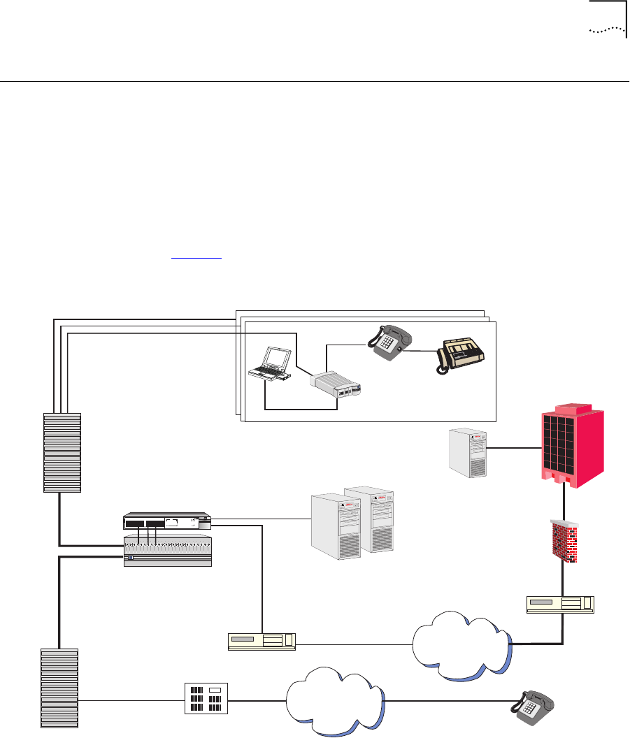
Figure 1 shows a typical MTU/MDU application.
Figure 1 MTU/MDU Visitor and Community Network Systems Application
When personal computer equipped with an Ethernet card is plugged into
the Ethernet port of the VCN AP, the system provides fast internet and
Ethernet
Ethernet
Regular
Phone
Cable
Ethernet
SuperStack II 1100 Switch
Phone Line
PBX
VPN Router
T1 to ISP
VPN Router
Firewall
Corporate
Intranet
Corporate
Server
Visitor Based
Networking Servers
VCN Access
Concentrator
Existing Phone
Lines
Punch-Down
Block
Punch-Down
Block
VCN AP
green
flashinggreen
off
=enabled,link OK
=disabled,link OK
=linkfail
Status
Module
Unit
3
3
4
4
6
6
5
5
7
7
8
8
9
9
10
10
11
11
12
12
1
1
2
23
5
1
4
7
6
8
2
13
13
14
14
15
15
16
16
17
17
18
18
19
19
20
20
21
21
22
22
23
23
24
24
SuperStackII
Switch3300
3C16980
Packet
Packet
Status
Status
Power/SelfTest
6x 7x
18x 19x
1x
13x
12x
24x
PSTN
Internet
3C10BSO24OA-C
3
Com
24Ports Concentrator
Fax-Modem
Fax-Modem
ETHERNET
ETHERNET
Line
Line
Power
Power
3
c
om

12 CHAPTER 1: OVERVIEW
other network services for data transmissions while allowing voice
channels to be used simultaneously.
The VCN AP connects to the VCN AC via a standard copper wire pair. The
VCN AC connects to the analog PBX or local telephone exchange and to
a 10 Base-T switch, e.g. 3Com® VCN Services Switch 10.
After connecting the telephone and the computer to the VCN AP, a
person can send data from his computer and speak on the telephone
simultaneously. An additional telephone extension based on the same
cable remains available for conversation but, does not go through the
VCN AC since the two telephones do not share the same wire pair.
Thus a hotel or a residence that installs Visitor and Community Network is
able to add many more communication services without losing any
existing capability.
The VCN AP joins voice and data channels in the direction of the VCN AC
and separates voice and data channels toward the end user.
The Visitor and Community Network System facilitates intra-campus data
communications over a high speed Local Area Network (LAN), i.e.,
Intranet. If the campus is connected to an ISP, the system enables the
users on the campus to use the Internet.
Existing LAN infrastructure can be extended to locations currently lacking
LAN cabling through the Visitor and Community Network system.
Services that do not need the LAN, for example, voice and fax, continue
to operate normally.
VCN Access Point
Features
The VCN Access Point has the following features:
■The VCN AP is a network access device that allows a user to have an
Ethernet data connection, available in most PCs and laptops, over a
telephone extension line and simultaneously use the same line for
telephone calls.
■Voice traffic is carried in its native frequency band over the copper pair
wire which connects the VCN AP to the VCN AC.
■The VCN AP combines voice and data in the direction of the VCN AC,
which separates voice and data, by sending voice to the analog PBX
VCN Access Point Features 13
and data to the SuperStack II 1100 Switch. The VCN AP also splits
voice and data in the direction from the VCN AC. Data is sent up to 10
Mbps full duplex.
The solution also works with the VCN Services Switch 10 and the
SuperStack II Switch 3300.
■The user’s Ethernet frames are encapsulated in HDLC frames carried in
VDSL. Voice and data traffic are carried in their respective frequency
ranges in the wire pair that connects the VCN AP to the VCN AC.
Voice traffic, including facsimile and analog modem traffic, are not
modified. Refer to Figure 2.
Figure 2 Transfer of Ethernet Frames to VDSL frames in VCN System
■The VCN AP supports 4-wire telephone cable. The additional 2 wires
which exist in every telephone cable will remain available for an
additional extension. In telephone sets that have two RJ-11 jacks, the
JUHHQ
IODVKLQJ#JUHHQ
RII
#HQDEOHG/#OLQ N #2.
#GLVDEOHG/#OLQN #2.
#OLQN#IDLO
6
6
7
7
9
9
8
8
:
:
;
;
<
<
43
43
44
44
45
45
4
4
5
5 6
8
4
7
:
9
;
5
46
46
47
47
48
48
49
49
4:
4:
4;
4;
4<
4<
53
53
54
54
55
55
56
56
57
57
6XSHU6WDFN#,,
6ZLWFK#6633
3C169 80
3DFNHW
3DFNHW
6WDWXV
6WDWXV
3RZHU26HOI#7HVW
9[:[
4;[4<[
4[
46[
45[
57[
3
24 Po rt s C on cen tra to r
Data frequency
Existing POTS metallic pair line
Ethernet
VCN AC
PBX
Ethernet switch
Voice frequency
VDSL frame
HDLC frame
Ethernet frame
Ethernet
POTS line
POTS lines
Voice call
Voice calls
VCN AP
Ethernet
frames
Ethernet
frames
14 CHAPTER 1: OVERVIEW
additional line may be used independently of the VCN AP for
connecting an analog modem or facsimile use.
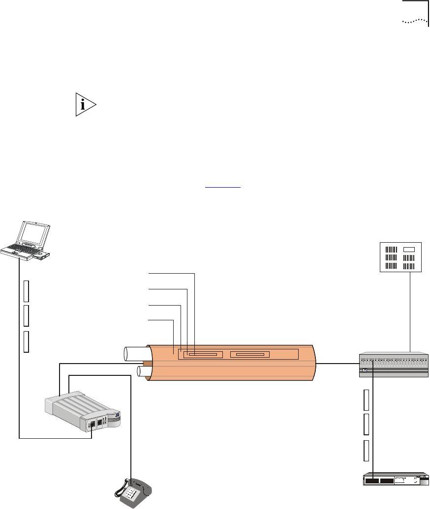
■The VCN AP supports remote software download of VCN APs and
VCN Access Concentrators through a special download menu and
through a special network configuration—the VCN AP is connected to
the Ethernet switch directly through the VCN AP Ethernet port. Refer
to Figure 3.
Figure 3 VCN AP Software Download Network Configuration
Operational Controls This section describes the connectors and LED indicators of the VCN AP.
Figure 4 displays the VCN AP Unit Front View.
Ethernet
Regular
Phone
Cable
Ethernet
VCN Services Switch 10
Phone Line
PBX
VCN Access
Concentrator
Existing Phone
Lines
Punch-Down
Block
Punch-Down
Block
VCN
Access Point
JUHHQ
IODV KL QJ#JU H HQ
RII
#HQD EO HG /#OLQN#2.
#GLVD EO H G/#OL QN #2.
#OLQN #IDLO
6
6
7
7
9
9
8
8
:
:
;
;
<
<
43
43
44
44
45
45
4
4
5
5 6
8
4
7
:
9
;
5
46
46
47
47
48
48
49
49
4:
4:
4;
4;
4<
4<
53
53
54
54
55
55
56
56
57
57
6XSHU6WDFN#,,
6ZLWFK#6633
3C16980
3DFNHW
3DFNHW
6WDW XV
6WDW XV
3RZ H U26HO I#7HVW
9[:[
4;[4<[
4[
46[
45[
57[
3
24 Ports Concentrator
Software Download
VCN Access Point
Management
Computer
User
Computer
VCN Access Point Features 15
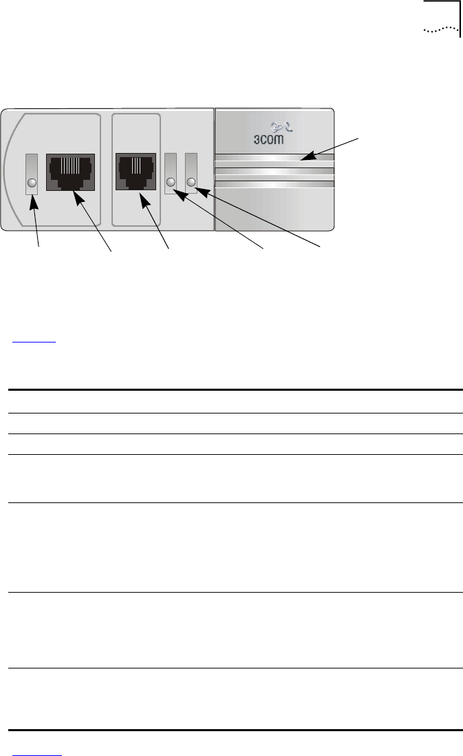
Figure 4 The VCN AP Unit Front View
Ta b l e 3 describes the LEDs and connectors on the front panel.
Figure 5 displays the back panel of the VCN AP.
Fax-ModemETHERNET
Line
Power
Ethernet
LED
Ethernet
port
Fax-Modem
port Power LED
Line LED
Local
Management
Connector
(hidden)
Ta b l e 3 The VCN Access Point LEDs and Connectors - Front View
Item Type State Used to
Ethernet LED Green Indicate connection of the VCN AP to a PC
Ethernet RJ-45 -Connect the VCN AP to a PC
Fax-
Modem
RJ-11 port -Connect a fax machine or a fax modem of a PC
for sending/receiving faxes or making dial-up
data transfers.
Line LED OFF indicate VCN AP is not connected to the line
Green Indicate connection of the VCN AP to the VCN
AC
Flashing
in Green
Indicate data transmission to the VCN AP
Power LED OFF Indicate that the VCN AP is not powered
Orange After 30 seconds, indicate that the
power-on-self-test (POST) failed
Green Indicate that the VCN AP is functional
LMI 4-pin
MiniDin
connector
(hidden)
-Connect the ASCII terminal for monitoring and
troubleshooting.
16 CHAPTER 1: OVERVIEW
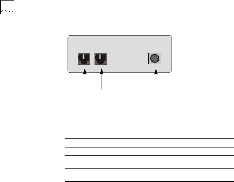
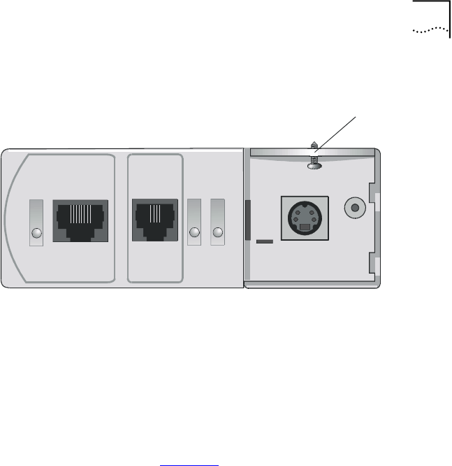
Figure 5 VCN AP Unit Back Panel
Ta b l e 4 describes the connectors on the back panel.
Ta b l e 4 The VCN AP Unit LEDs and Connectors - Back Panel
Item Type State Used to
Telephone RJ-11 port -Connect the telephone set
Line RJ-11 port -Connect the VCN AP to the room
telephone socket
DC-IN 8-pin MiniDIN DC Power
port
-Connect the AC/DC adapter
PHONE LINE DC-IN
Telephone
port Line port 5Vdc
Power
Socket

2SAFETY INFORMATION
This chapter provides safety information in English, French and German.
The topics covered in this chapter are:
■Safety Precautions
■Précautions de sécurité concernant le VCN Access Point
■Sicherheitsvorkehrungen für den VCN Access Point
Safety Precautions The following safety precautions should be taken before installing the
VCN Access Point:
To reduce the risk of electrocution and fire:
■All servicing should be undertaken only by qualified service personnel.
There are no user serviceable parts in the unit.
■Do not plug in, turn on or attempt to operate an obviously damaged
unit.
■DO not operate the unit in a location where the maximum ambient
temperature exceeds 40 degrees C.
■Be sure to unplug the power supply cord from the wall socket before
attempting to remove and/or replace the unit.
■The power supply provides for automatic selection of either 100-120
Vac or 200-240 Vac, 60/50 Hz, as indicated on the safety label
adjacent to the power inlet. Ensure that the available voltage supply at
the mains is within one of these two ranges.
■Use only the special power adapter supplied with the unit.

18 CHAPTER 2: SAFETY INFORMATION
Précautions de
sécurité concernant
le VCN Access Point
Attention: Réduisez les risques d'electrocution et d'incendie
■Toute intervention sera effectuée uniquement par un personnel
qualifié. L'unité ne comporte pas de pièces à remplacer par
l'utilisateur.
■Si l'unité est visiblement endommagée ne pas la brancher au secteur,
ni tenter de la mettre en fonction.
■Ne pas faire fonctionner l'unité dans un endroit où la température
ambiante dépasse 40 degrés C.
■Assurez vous que vous avez bien débranché le câble d'alimentation
électrique de la prise de courant avant d'essayer de déplacer ou de
remplacer l'unité.
■Le bloc d'alimentation sélectionne automatiquement la tension
d'entrée (soit 100-120 V soit 200-240 V, alternatif 60/50 Hz) comme
indiqué sur l'étiquette de sécurité apposé à côté de la prise.
Assurez-vous que la tension disponible au secteur se trouve dans la
plage appropriée.
■N'employez que l'adaptateur d'alimentation fourni avec l'unité.
Sicherheitsvorkeh-
rungen für den VCN
Access Point Warnung: Um das Risiko eines elektrischen Stromschlages mit möglicher
Todesfolge und eines Feuers zu reduzieren:
■Alle Wartungsdienste sollten nur von qualifiziertem Wartungspersonal
durchgeführt werden. Die Einheit enthält keine Teile, die der Benutzer
selbst warten kann.
■Schließen Sie die Einheit unter keinen Umständen an das Stromnetz
an, schalten diese ein oder versuchen diese zu benutzen, wenn die
Einheit klar erkennbar beschädigt ist.
■Bedienen Sie die Einheit nicht, wenn die Temperatur am Standort 40
Grad C übersteigt.
■Ziehen Sie den Stromstecker aus der Steckdose, bevor Sie die
Energieversorgung entfernen und/oder austauschen.

Sicherheitsvorkehrungen für den VCN Access Point 19
■Die Energieversorgung wählt automatisch entweder 100-120 V WS
oder 200-240 V WS, 60/50 Hz, wie auf dem Sicherheitsaufkleber
neben der Energiezufuhr angegeben. Gewährleisten Sie, daß die
vorhandene Stromleistung des Hauptstromnetzes innerhalb eines
dieser möglichen Bereiche liegt.
■Verwenden Sie nur den besonderen Adapter, der mit der Einheit
geliefert wird.

20 CHAPTER 2: SAFETY INFORMATION
3INSTALLING AND OPERATING THE
VCN ACCESS POINT
This chapter provides the information about installing, setting up,
powering up and operating the VCN Access Point. The following topics
are described:
■Prerequisites for Installation
■Installing the VCN Access Point
■Operating the VCN Access Point
Prerequisites for
Installation
Before installing the VCN AP, check that you have all the necessary
components and accessories listed in Ta b l e 5 and that you have the
required outlets in the room where you will be installing the unit.
The initial communications setup in a room is illustrated in the Figure 6.
Figure 6 Initial Room Communications Setup
The accessories needed for installation are included in the package
provided with the VCN AP set. Prior to carrying out installation, compare
the VCN AP package contents with items listed in Ta b l e 5 :
Ta b l e 5 Unpacking List
NO. Item Quantity Supplied by
1VCN AP 13Com
2PC (desktop, laptop or
palm held) equipped with
Ethernet Card.
1End User
Telephone
Socket

22 CHAPTER 3: INSTALLING AND OPERATING THE VCN ACCESS POINT
The VCN AC must be installed before the VCN AP. Refer to the Visitor
and Community Based Networking Concentrator Unit Service Manual.
Installing the VCN
Access Point
The VCN AP may be conveniently mounted on one the following:
■a wall, see page 23.
■under a table, see page 27.
■on top of a table, see page 32.
3ac/dc adapter 13Com
4Line cable (RJ-11) 13Com
5Laptop/PC cable (RJ-45) 1End User or Customer on Request
6FAX cable (RJ-11) 1End User or Customer on Request
74-pin MiniDIN Control
Cable
13Com, for Local Management or
Troubleshooting Only
8Long screws133Com
9Short screws1,2 33Com.
10 Wall anchors133Com
11 Template213Com, for Installation only
12 Rubber pads3 4 3Com
1For VCN AP wall installation
2For installing VCN AP under the table
3For VCN AP table top installation
Ta b l e 5 Unpacking List (continued)
NO. Item Quantity Supplied by
Installing the VCN Access Point 23
Mounting the VCN
Access Point on a
Wall
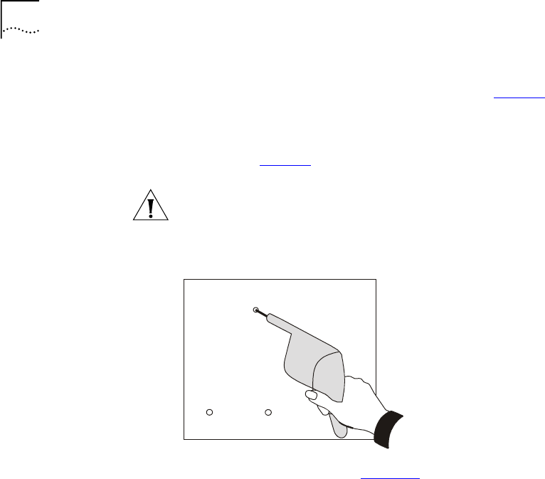
To mount the VCN AP on a wall perform the following tasks.
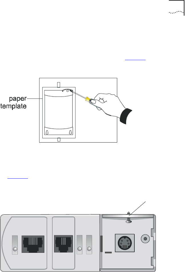
1Apply the paper template to the wall as shown in Figure 7.
Figure 7 Using the Paper Template to Mark the Wall
The partially curved edge of the template corresponds to the curved cover
that is part of the VCN AP front panel.
2Remove the cover by sliding it downward and then pulling it outward.
See Figure 8.
Figure 8 Removing Curved Cover
All three holes in the VCN AP are plugged.
3Remove the plugs from the two large holes by prying them out with the
tip of your screwdriver.
4Remove the plug from the small hole by forcing it out from the bottom
with a pointy instrument (for example a nail).
Fax-ModemETHERNET
Line
Power
S
crew hole
24 CHAPTER 3: INSTALLING AND OPERATING THE VCN ACCESS POINT
5Where the three crosshairs of the template holes intersect, indent the
surface with a sharp tool (for example a nail). See Figure 7.
6Remove the template.
7Drill the indented holes with a drill bit of the same diameter as the wall
anchors. See Figure 9.
Note: If the provided anchors are not suited to your wall, you must obtain
and insert suitable anchors that match the diameter of the provided
screws.
Figure 9 Drill Holes for Anchors
8Insert the three anchors. See Figure 10.
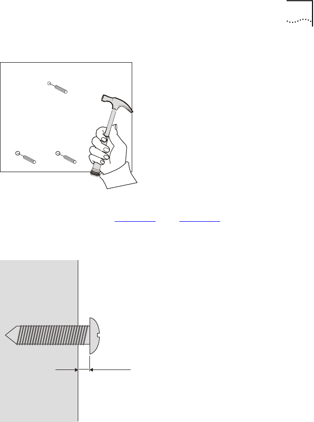
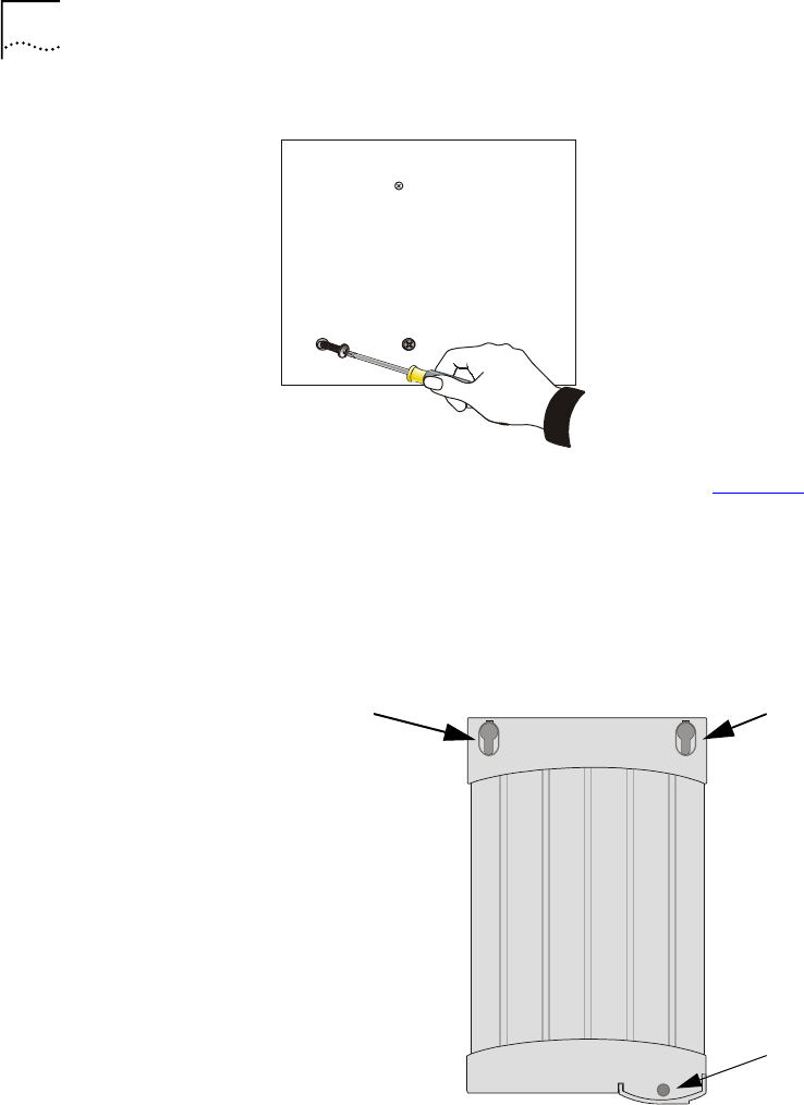
26 CHAPTER 3: INSTALLING AND OPERATING THE VCN ACCESS POINT
Figure 12 Driving Screws into the Wall
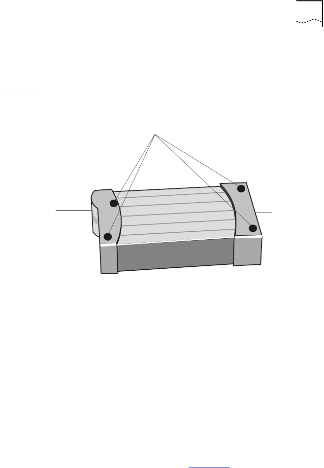
10 Align the two large holes of the VCN AP (see Figure 13) with the two
already driven screws and insert the screw heads into the holes .
Shift the VCN AP downward so that the screw shanks slip into the slots
and the topmost indented hole is aligned with the VCN AP's small screw
hole.
Figure 13 Screw Holes in the Top of the VCN AP
11 Drive the last screw into the wall anchor to the full depth.
Large hole
Large hole
Small screw hole
Installing the VCN Access Point 27
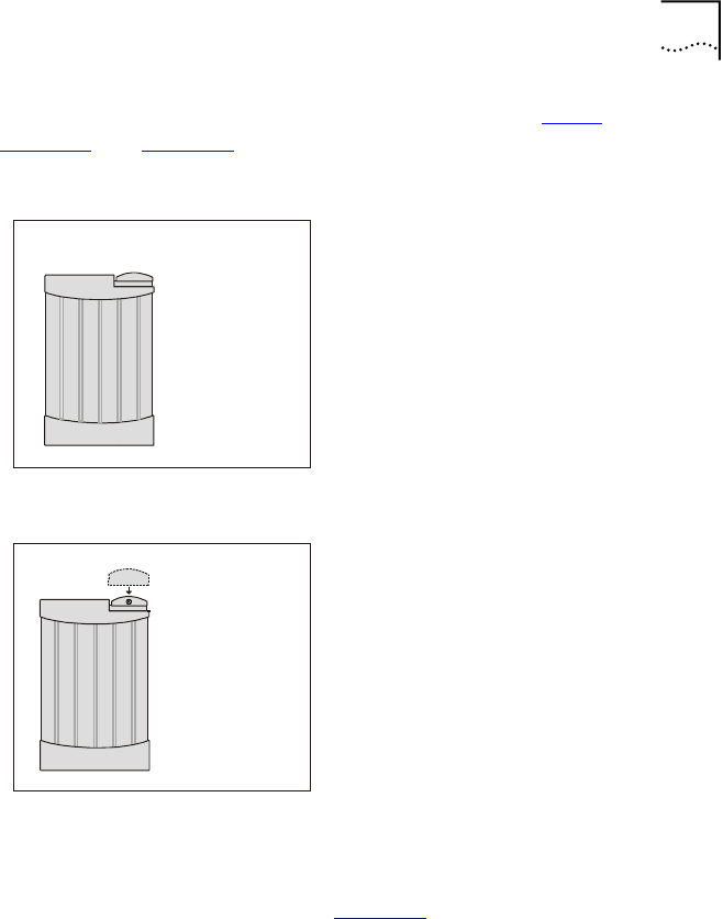
12 Reinsert the curved cover by reversing the sequence of step 2. See
Figure 14 and Figure 15.
Figure 14 VCN AP without Curved Cover
Figure 15 Placing Curved Cover on VCN AP
Mounting the VCN
Access Point Under a
Ta b l e
Two screws support the rear side of the VCN AP and an additional screw
is used to fasten its front. Find an appropriate location for the VCN AP on
the lower surface of a table, as in Figure 16.
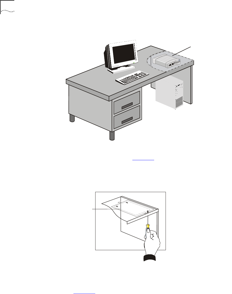
28 CHAPTER 3: INSTALLING AND OPERATING THE VCN ACCESS POINT
Figure 16 Mounting Underneath a Table
To mount the VCN AP under a table, perform the following tasks:
1Tape the paper template (see Figure 17) to the under side of the table.
Make sure that the straight edge is farthest away from you and the
partially curved edge is nearest to you.
Figure 17 Using the Paper Template to Mark the Table
The partially curved edge of the template corresponds to the curved cover
that is part of the VCN AP's front panel.
2Remove the cover by sliding it downward and then pulling it outward.
See Figure 18.
VCN AP Mounted
to Underside of
Table Top
paper
template
Installing the VCN Access Point 29
Figure 18 Removing Curved Cover
All three holes in the VCN AP are plugged.
3Remove the plugs from the two large holes by prying them out with the
tip of your screwdriver.
4Remove the plug from the small front hole by forcing it out from the
bottom with a pointy instrument (for example, a nail).
5Where the crosshairs of the template holes intersect, indent the surface
with a sharp tool (for example, a nail).
6Remove the template. See Figure 17.
Fax-ModemETHERNET
Line
Power
S
crew hole
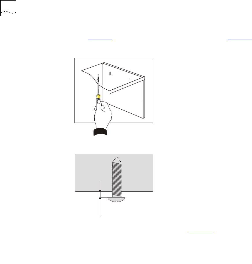
30 CHAPTER 3: INSTALLING AND OPERATING THE VCN ACCESS POINT
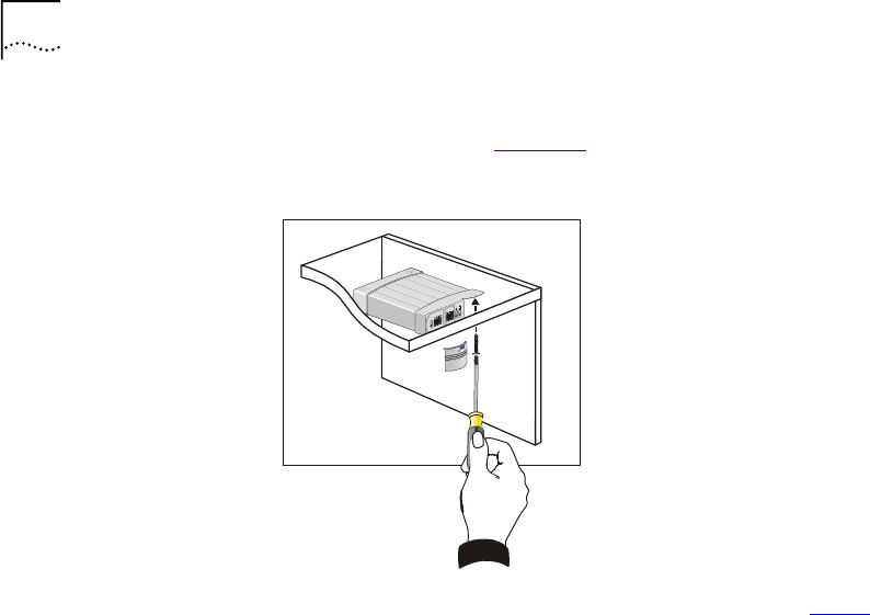
7Insert two of the three short screws provided into the farthest indented
holes (Figure 19) and drive them to the distance indicated in Figure 20.
Figure 19 Driving Two Screws into the Table
Figure 20 Offset of the Screw Head from the Table
8Align the two large holes of the VCN AP (see Figure 21) with the two
already driven screws.
9Insert the screw heads into the holes and then shift the VCN AP forward
so that the screw shanks slip into the slots and the closest indented hole
is aligned with the VCN AP's small screw hole. See Figure 22.
7/64 in
25 - 3mm
.
.
Installing the VCN Access Point 31
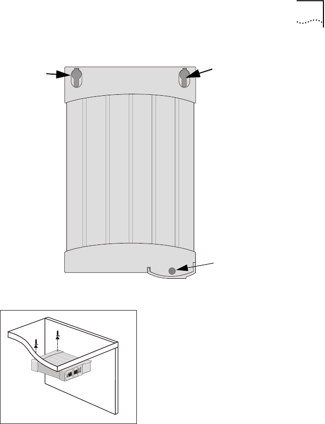
Figure 21 Screw Holes in the Top of the VCN AP
Figure 22 Inserting the VCN AP under the Table
Large hole
Large hole
Small screw hole
32 CHAPTER 3: INSTALLING AND OPERATING THE VCN ACCESS POINT
10 Drive the last short screw through the small screw hole and into the
surface full depth. See Figure 23.
Figure 23 Completion of Mounting the VCN AP Under the Table
11 Reinsert the curved cover by reversing the sequence of step 2.
Placing the VCN AP
on Top of a Table
Four rubber pads must be attached to the VCN AP bottom to provide
stability when the VCN AP is used on top of a table.
Installing the VCN Access Point 33
To mount the VCN AP on top of a table perform the following tasks:
1Stick the four rubber pads to the bottom of the VCN AP as shown in
Figure 24.
Figure 24 Preparing VCN AP for Table Top Use
2Turn the VCN AP over and place it on top of a table near the ac power
and telephone sockets in the room.
Connecting the VCN
AP
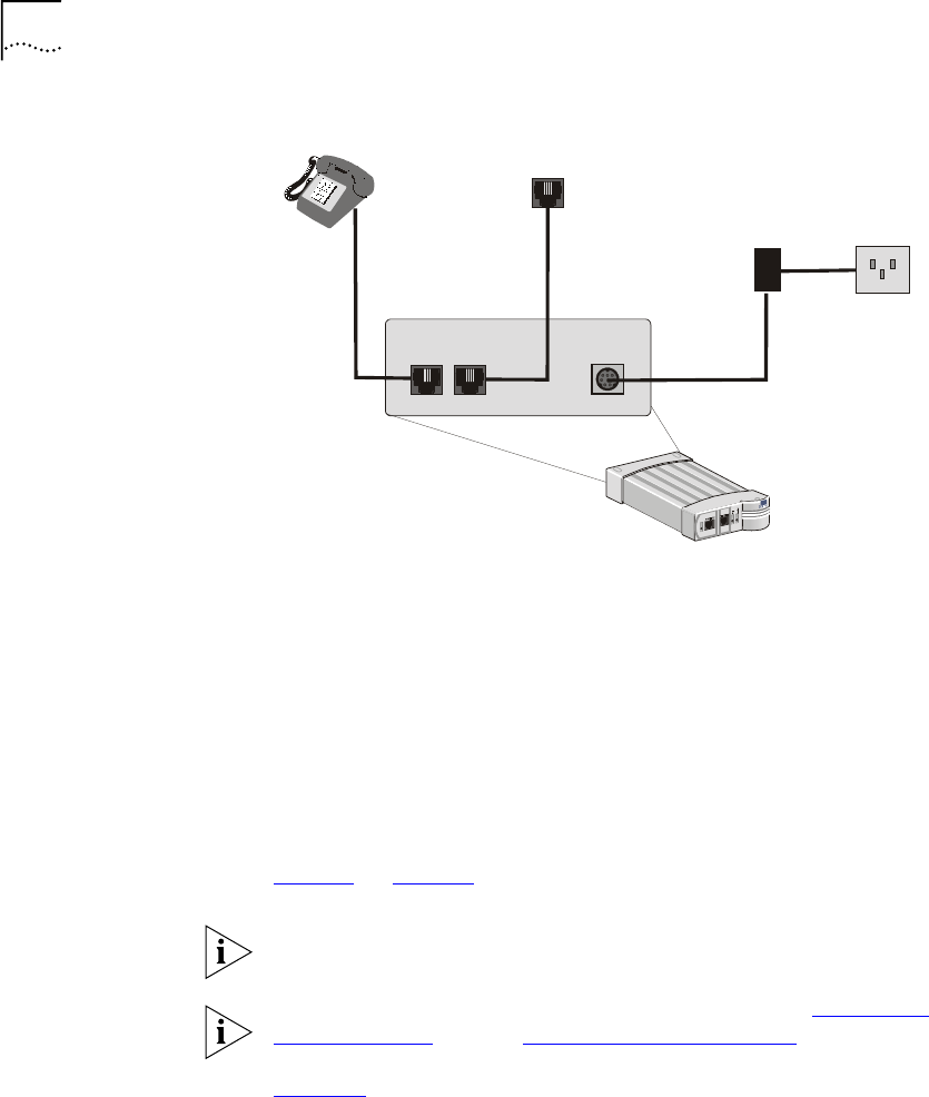
To enable VCN AP operation, connect the following from the rear of the
unit:
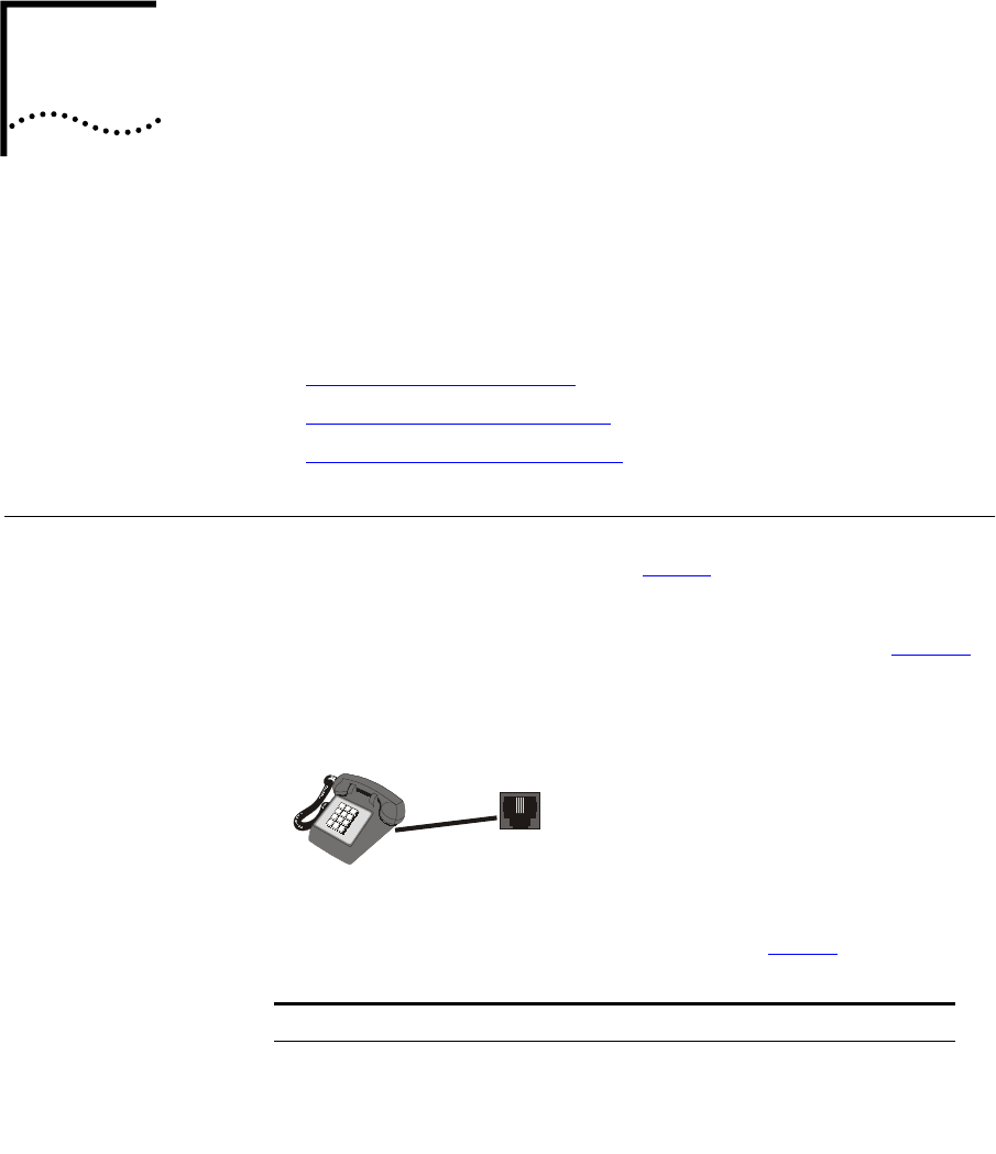
■Connect the RJ-11 cable coming out from the telephone set to the
VCN AP PHONE port at the front.
■Connect an RJ-11 cable from the VCN AP LINE port to the wall
telephone socket.
■Connect the ac/dc adapter to the DC-IN port in the VCN AP and to the
ac power socket in the room.
The resulting connections are illustrated in Figure 25.
Local
Management
Section
Rear
Panel
Attach Four Rubber Pads
34 CHAPTER 3: INSTALLING AND OPERATING THE VCN ACCESS POINT
Figure 25 Preparation of the VCN Access Point
■Connect an RJ-45 cable from the user’s PC to the Ethernet port at the
front of the VCN AP. The user’s PC must be equipped with an Ethernet
card. If the user’s PC does not have an Ethernet card installed, the
modem card connects in the Fax-Modem port at the front of the VCN
AP. In such case, the data does not go through the VDSL line and
cannot make use of the 10 Mbps full duplex connectivity.
■If the telephone set has an additional RJ-11 port, it can be used
independently of the VCN AP for fax or modem.
Thirty seconds after the VCN AP is connected to power, check that the
Power and Line LEDs on the VCN AP front panel are green. Refer to
Figure 8 on page 23.
The VCN AP does not have an ON/OFF switch. The unit is powered on as
soon as it is connected to ac power.
If the LEDs on the VCN AP do not turn green, refer to Appendix A
Troubleshooting, section “Power-on Self Test (POST)”.
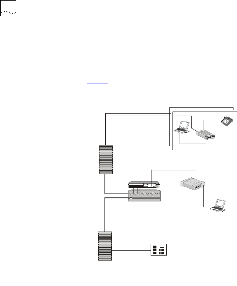
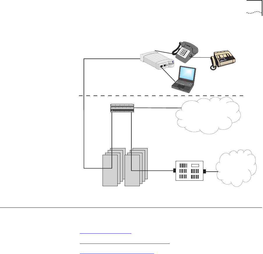
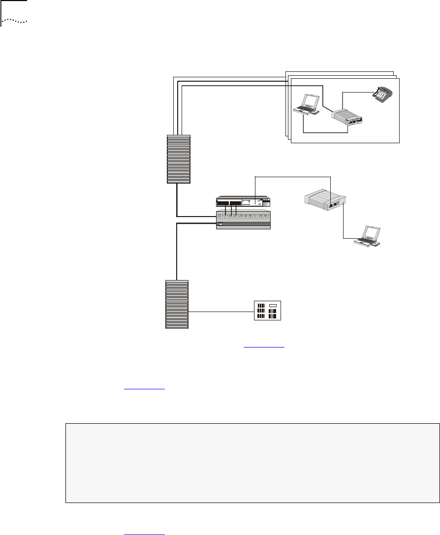
Figure 26 illustrates the VCN Access Point-VCN Access Concentrator
network after the VCN AP is installed and a user computer is attached to
the VCN AP. The user has both access to the Public Switched Telephone
Network (PSTN) and a high speed connection to an Internet Service
Provider (ISP) as well as an additional connection to a fax or Modem.
telephone
socket
ac/dc
adapter ac power
socket
VCN Access Point
DC-IN
LINE
PHONE
Operating the VCN Access Point 35
Figure 26 Communications Access via the VCN AP
Operating the VCN
Access Point
After the installing and mounting the VCN Access Point it is ready for use.
The VCN AP may be used for the following:
■Making a Voice Call
■Sending and Receiving Data Traffic
■Sending and Receiving Faxes
Making a Voice Call You can make a voice call without connecting the VCN AP to power or to
any front panel connection.
To place a voice call:
1Check that the telephone port is connected to a telephone set and the
LINE port on the rear of the VCN AP is connected to the wall telephone
socket.
2Use the telephone set as if it were connected directly to the wall socket.
Fax-Modem
ETHERNET
Line
Power
3
c
om
VCN
Access Point
VCN Access
Concentrator
Punch-Down Blocks
24 wire pairs
24 wire pairs
24 wire pairs
Basement
ISP / INTERNET
NSP / PSTN
Room
PBX
24 wire pairs
24Ports Concentrator
3C10BSO24OA-C
123456789
10 11 12 13 14 15 16 17 18 19 20 21 22 23 24
LINE
LAN
POWER
3
Com

36 CHAPTER 3: INSTALLING AND OPERATING THE VCN ACCESS POINT
3If the telephone set has an additional RJ-11 port, it can be used
independently of the VCN AP for fax. Connect an RJ-11 cable between
the fax machine or the PC fax modem to the PC RJ-11 port on the VCN
AP.
Sending and
Receiving Data Traffic
To send or receive data traffic:
1Connect a RJ-45 cable between the Ethernet port and the PC Ethernet
card.
NOTE: No password or account number specific to the local ISP is
needed, however, your normal log-in procedure should be observed,
including access privileges like user ID, password, etc.
2Run your network application: browser, e-mail etc.
Sending and
Receiving Faxes
You can make a fax call without connecting the VCN AP to power.
To send or receive faxes:
1Connect a RJ-11 cable between the fax machine or the PC fax modem
and the VCN AP Fax-Modem port.
2Use the fax machine and the telephone set in accordance with the fax
machine user manual.
3If the telephone set has an additional RJ-11 port, it can be used
independently of the VCN AP for fax or modem. Connect an RJ-11 cable
between the fax machine or the PC fax modem to the PC RJ-11 port.

4USING THE LOCAL MANAGEMENT
ACCESS
This chapter describes using the Local Management Access (LMA) and
remote management. The LMA is accessible via a terminal emulating
computer connected to the LMA port on the VCN Access Point. The
terminal is used for monitoring and problem solving. Remote software
downloading is done via a Telnet program which can monitor the VCN
Access Concentrator from a remote terminal.
The following topics are described:
■Using the Management Terminal
■VCN Access Point Menus
■Remote Software Download
Using the
Management
Te r m i n a l
A computer with terminal emulation software provides the user interface
to the local management of the VCN Access Point.
Management
Te r m i n a l
Requirements
For service and maintenance, use a PC equipped with a terminal
application capable of 115,200 bps serial communication with a VCN AP.
Refer to Appendix E Terminal Emulation Settings.
The cable for connecting the management computer has a DB 9 pin
connector for the computer and a 4 pin MiniDIN connector for the VCN
AP LMA port. If you do not have the cable, contact your 3Com
representative. Refer to Appendix D Pin Assignments for LMA Cable for a
detailed description of the cable and the LM connectors.
38 CHAPTER 4: USING THE LOCAL MANAGEMENT ACCESS
Connecting the PC
Terminal Emulator
Perform the steps below to connect the PC to the LMA port:
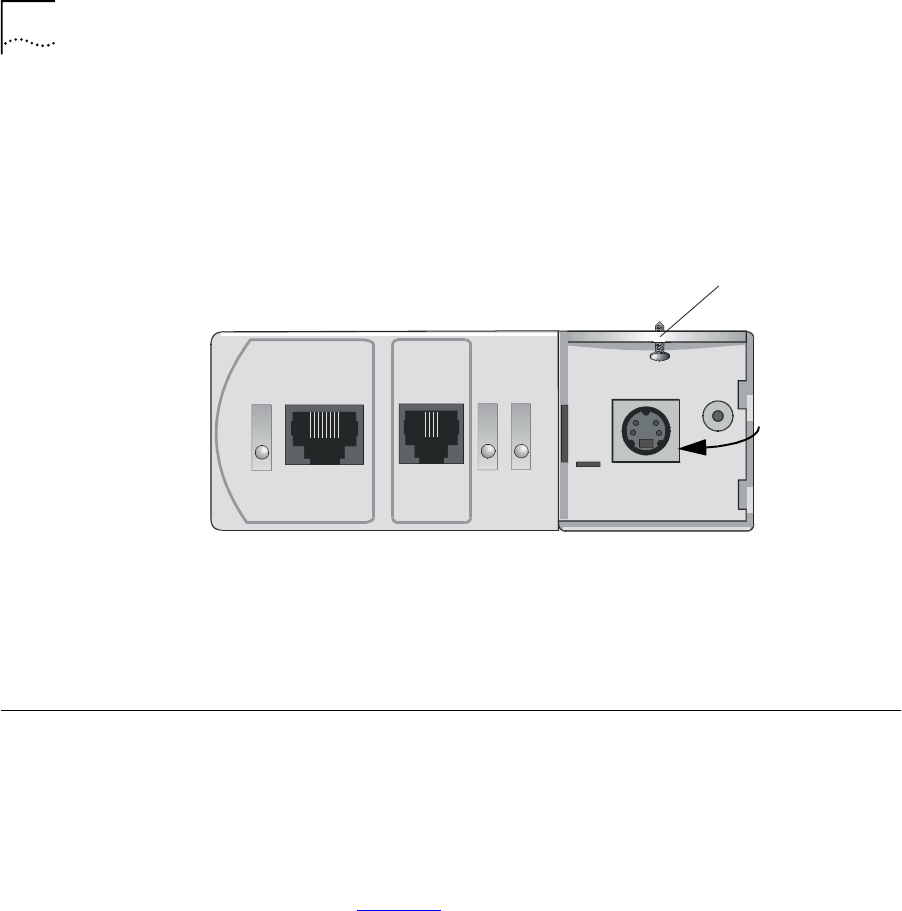
1Remove the cover from the LMA section of the VCN AP as in the figure
below.
Figure 27 LMA Section of the VCN Access Point
2Connect the LMA port to the PC serial port (COM1 or 2) with the cable
provided you; if you do not have the cable, contact 3Com. Plug the end
of the cable with the a four-pin MiniDIN connector into the VCN AP LMA
port.
VCN Access Point
Menus
This section describes the menus.
Summary and
Structure of the
Menus
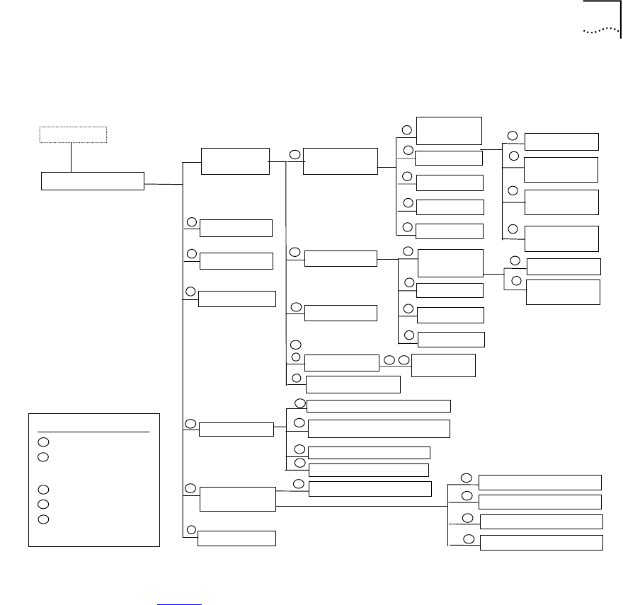
This section provides a menu hierarchy to describe the structure of the
menu system and a menu summary to help the network administrator
use the management system efficiently.
The chart in Figure 28 summarizes the menu hierarchy. The abbreviations
next to the menu names are suggestions for how the menus are used.
Most of the menus labeled D are not described further in this chapter
since they are used mainly by developers for debugging. The debug
menus for performing loopbacks are described since loopbacks can be
used by network administrators to solve problems.
Fax-ModemETHERNET
Line
Power
S
crew hole
Local
Management Port
VCN Access Point Menus 39
Figure 28 Menu Hierarchy
Ta b l e 6 provides a summary of the line card menus, the submenus and
the corresponding number sequence. Click a menu or submenu name to
receive more information.
After typing each number in the number sequence press the <Enter> key.
Access Point Main Menu
Login Process
Monitoring system
operation and problem
reporting
M
KEY
Debug, for developers
use only
D
Software Download
S
Problem Solving
P
CConfiguration
PAP Version
Management
Menu
Debug Menu
Test Control
Flash Actions
Ethernet
Menu
Change
Work Mode
P
Ethernet Status
Traffic Counters
P
M
Reset Counters
P
VDSL Control QAM Channel Status
Set Normal Mode
P
D
P
D
Set Internal
Loopback Mode
Set External
Loopback Mode
Set Full Duplex
Mode
Reset All Counters
Tasks Info Menu
Change
Work Mode
HDLC Status
Traffic Counters
P
M
Reset Counters
P
D
HDLC Menu Set Normal Mode
D
DSet Internal
Loopback Mode
Operation
Mode Selector
S D
Reset Board
C
Change Password
Set VLAN ID for Management
C
Set to Factory Defaults
C
AP Configuration
Set Ethernet Half/Full Duplex Mode
C
Read BCM6010 register
I2C control
VDSL print
Write BCM6010 register
D
D
D
D
M
C
M
P
S
P
D
M
M
D
D
D
Learning Table
C

40 CHAPTER 4: USING THE LOCAL MANAGEMENT ACCESS
Login After connecting the management terminal to one of the LMA ports 2
through 24, press any key. The login dialog appears:
Login:
Type your Login ID and press <Enter>.
Password:
Type your password and press <Enter>.
Ta b l e 6 Number Sequence Corresponding to Submenus
Menu Name Submenu
Number
Sequence
Access Point Main Menu
AP Version 1
Management Menu 3
The Ethernet Menu 31
Ethernet Traffic Counters 3 1 1
Ethernet Status 3 1 2
Reset Counters 3 1 3
Change Ethernet Work Mode Menu 3 1 4
The HDLC Menu 3 2
HDLC Traffic Counters 3 2 1
HDLC Status 3 2 2
Reset Counters 3 2 3
Change HDLC Work Mode 3 2 4
Reset All Counters 3 4
Reset the Board 3 5
VDSL Menu 4
VDSL QAM Channel Status Report 4 1
AP Configuration Menu 7
Set VLAN ID for Management 7 1
Set Ethernet Half/Full Duplex Mode 7 2
Change Password 7 3
Set to Factory Defaults 7 4

VCN Access Point Menus 41
The default login is admin; the default password is null—just press
<Enter>.
If you forget your password, contact technical support. Refer to
Appendix F Technical Support.
When you complete Login, the Access Point Main Menu appears. If the
login was unsuccessful, the following message appears:
Login incorrect
Access Point Main
Menu
In reconnecting to the VCN AP, the last used menu often appears. In most
menus, except where indicated, the option labeled 0 is for returning to a
higher level menu (Figure 29).
Figure 29 Return to Previous Menu Option
Press any key to view the Access Point Main Menu on the terminal screen.
If another menu appears, type 0 (zero) and press <Enter> repeatedly until
the Access Point Main Menu appears.
Figure 30 VCN AP Main Menu
0. Return to previous menu
Access Point Main Menu
----------------------
1. AP Version
2. Debug Menu
3. Management Menu
4. VDSL control
5. Test control
6. Flash actions
7. AP Configuration
8. Software Download Menu
0. Exit
Please enter your choice:

42 CHAPTER 4: USING THE LOCAL MANAGEMENT ACCESS
AP Version Confirm VCN AP functionality by checking the software and hardware
versions and dates.
1To check the software version, enter 1 In the Main Menu (Figure 30,
page 41). The following screen appears:
Figure 31 Version Screen
2Press <Enter> to return to the Main Menu.
Management Menu To d i s p l a y t h e Management Menu, type 3 in the Main Menu and press
<Enter>. The Management Menu appears:
Figure 32 VCN AP Management Menu
The Ethernet Menu To view the Ethernet Menu:
System Display
--------------
HW Version: 1.0
SW Version: 3.5
SW Date: Jul 23 2000,
SW Time: 15:56:28
Press ENTER to continue ...
Management Menu
----------------
1. Ethernet Menu
2. HDLC Menu
3. Tasks Info Menu
4. Reset All Counters
5. Reset Board
0. Return To Previous Menu
Please enter your choice:

VCN Access Point Menus 43
1In the VCN AP Main Menu enter 3.
2In the Management Menu, enter 1. The Ethernet Menu appears
Figure 33 Ethernet Menu.
Ethernet Traffic Counters
The Ethernet traffic counters count normal frames and errored frames
transferred between the user’s PC and the VCN AP.
Ethernet Menu
-------------
1. Traffic Counters
2. Ethernet Status
3. Reset Counters
4. Change Work mode
5 Learning table
0. Return to previous menu
Please Enter your choice:

44 CHAPTER 4: USING THE LOCAL MANAGEMENT ACCESS
To check the Ethernet traffic counters, type 1 in the Ethernet Menu and
press <Enter>; the Ethernet Traffic Counters screen appears:
Figure 34 Ethernet Traffic Count Screen
Ethernet Status
To check Ethernet status, press 2 in the Ethernet Menu; the Ethernet
Status screen appears:
Figure 35 Ethernet Status Screen
Ethernet traffic counters
-------------------------
transmit counters
Tx frames - 6107
Tx error - 0
Discarded - 0
Receive counters
Rx frames - 159
Crc errors - 0
Discarded - 0
Alignment error - 0
Overrun - 0
Collision - 0
Frame too long - 0
Frame too short - 0
press <Enter> to continue
Ethernet Status
---------------
Scc channel numbers - 2
Work Mode - normal mode
Transmit enable - yes
Receive Enable - yes
Heartbeat checking - no
Retry Limit - 15
Maximum length of rx frame - 1522
Maximum length of tx frame - 64 bytes
press <Enter> to continue...

VCN Access Point Menus 45
Reset Counters
To reset Ethernet counters:
1In the Ethernet Menu, type 3 and press <Enter>. The following message
appears:
Do you want to proceed (Y/[N])? :
2Ty p e y and press <Enter> to perform the reset. The following message
appears:
The action has been done !
Learning Table
To view the MAC and IP addresses of the user’s PC, type 5 in the Ethernet
Menu and press <Enter>. If a PC is connected, the Learning Table in
Figure 36 appears.
Figure 36 A Typical MAC Address Display
If a PC is not connected, the message in Figure 37 appears.
Figure 37 Station not Connected Message
Change Ethernet Work Mode Menu
To change the Ethernet loopback mode or the duplex mode, use the
Change Work Mode Menu. In the Ethernet Menu, type 4 and press
<Enter>. The options in Figure 38 appear.
Learning table:
---------------
MAC address: 00-60-08-BC-F7-7F
IP address : 191.28.68.25
Press <Enter> to continue.......
Learning table:
---------------
Station not connected
press <Enter> to continue...

46 CHAPTER 4: USING THE LOCAL MANAGEMENT ACCESS
Figure 38 Change Work Mode Menu
In the Change Work Mode Menu, the current working mode is shown to
be one of:
■Normal Operation
Normal operation is lack of loopbacks and half duplex.
■Internal Loopback Mode
■External Loopback Mode
■Full Duplex Mode
The full duplex mode is displayed if a previous operation changed the
mode to full duplex.
Refer to Setting Duplex Mode, on page 47, for changing the duplex
mode.
Setting Internal Loopback Mode
To set internal loopback mode, type 2 and press <Enter>. The message
appears:
This action will change the working mode of Ethernet!
Do you want to proceed (Y/[N])? :
To c o n f i r m t y p e y; to discard, type n; and and press <Enter>.
When you proceed, the message appears:
Action has been done.
Change Work Mode Menu
---------------------
Current Working Mode of Ethernet: Normal Operation
1. Set Normal Mode
2. Set Internal Loopback Mode
3. Set Extenal Loopback Mode
4. Set Full Duplex Mode
0. Return to Previous Menu
Please enter your choice:

VCN Access Point Menus 47
When you discard the operation, the message appears:
The action has been canceled
Setting External Loopback Mode
To set external loopback mode, type 3 and press <Enter>. The message
appears:
This action will change the working mode of Ethernet!
Do you want to proceed (Y/[N])? :
To c o n f i r m t y p e y; to discard, type n; and and press <Enter>.
When you proceed, the message appears:
Action has been done.
When you discard the operation, the message appears:
The action has been canceled
Setting Normal Mode
To set normal mode, type 1 and press <Enter>. The message appears:
This action will change the working mode of Ethernet!
Do you want to proceed (Y/[N])? :
To c o n f i r m t y p e y; to discard, type n; and and press <Enter>.
When you proceed, the message appears:
Action has been done.
When you discard the operation, the message appears:
The action has been canceled
Normal mode is both lack of loopbacks and half duplex operation.
Setting Duplex Mode
To change the duplex mode to full, type 4 in the Change Work Mode
Menu, and press <Enter>. The messages appear:

48 CHAPTER 4: USING THE LOCAL MANAGEMENT ACCESS
This action will change the working mode of Ethernet!
Note: the change will NOT be saved after reset.
For changing and saving use the configuration menu
Do you want to proceed (Y/[N])? :
To c o n f i r m t y p e y; to discard, type n; and and press <Enter>.
When you proceed, the message appears:
Action has been done.
When you discard the operation, the message appears:
The action has been canceled
The HDLC Menu To view the HDLC Menu,
1In the Main Menu type 3 and press <Enter>. The Management Menu
appears (Figure 32).
2In the Management Menu type 2 and press <Enter>. The HDLC Menu
appears (Figure 39).
Figure 39 HDLC Menu.
HDLC Traffic Counters
The HDLC traffic counter counts normal frames and errored frames over
the common telephone and data line, thus indicating the behavior of the
connection between the VCN AP and the VCNAC.
To check the HDLC traffic counters, type 1 in the HDLC Menu and press
<Enter>; the HDLC Traffic Counters Screen appears (Figure 40).
HDLC Menu
--------
1. Traffic Counters
2. HDLC Status
3. Reset Counters
4. Change Work mode
0. Return to previous menu
Please Enter your choice:
HDLC Menu
----------
1. Traffic Counters
2. HDLC Status
3. Reset counters
4. Change Work mode
O. Return to previous menu
Please Enter your choice... :

VCN Access Point Menus 49
Figure 40 HDLC Traffic Counters Screen
Reset Counters
To reset HDLC counters:
1In the HDLC Menu, type 3 and press <Enter>. The message appears:
Do you want to proceed(Y/[N])? :
2Ty p e y and press <Enter> to perform the reset.
HDLC Status
To check HDLC status, enter 2 in the HDLC menu; the HDLC Status screen
appears:
HDLC Traffic Counters
---------------------
Transmit counters
Tx frames - 3
Retransmissions - 0
Tx errors - 0
Discards - 0
Receive counters
Rx frames - 6
Crc errors - 10219
Discards - 0
Abort sequences - 23017
Overruns - 0
Not mine - 0
Frames too long - 0
Dpll errors - 0
Frames not aligned - 39201
Press ENTER to continue ...

50 CHAPTER 4: USING THE LOCAL MANAGEMENT ACCESS
Figure 41 HDLC Status Screen
Change HDLC Work Mode
To change the HDLC loopback mode, use the Change Work Mode Menu.
In the HDLC Menu, type 4 and press <Enter>. The options in Figure 42
appear.
Figure 42 Change HDLC Work Mode Menu
In the Change Work Mode Menu, the current working mode is shown to
be one of:
■Normal Operation
Normal operation is lack of loopbacks.
■Internal Loopback Mode
Setting Internal Loopback Mode
To set internal loopback mode, type 2 and press <Enter>. The message
appears:
This action will change the working mode of HDLC!
HDLC Status
------------
Scc channel numbers - 3
Work Mode - normal mode
Transmit enable - yes
Receive Enable - yes
Maximum length of rx frame- 1518
press <Enter> to continue...
Current Working Mode of HDLC: Normal Operation
1. Set Normal Mode
2. Set Internal Loopback Mode
0. Return to Previous Menu
Please enter your choice:

VCN Access Point Menus 51
Do you want to proceed (Y/[N])? :
To c o n f i r m t y p e y; to discard, type n; and and press <Enter>.
When you proceed, the message appears:
Action has been done.
When you discard the operation, the message appears:
The action has been canceled
Setting Normal Mode
To set normal mode, type 1 and press <Enter>. The message appears:
This action will change the working mode of HDLC!
Do you want to proceed (Y/[N])? :
To c o n f i r m t y p e y; to discard, type n; and and press <Enter>.
When you proceed, the message appears:
Action has been done.
When you discard the operation, the message appears:
Normal mode is lack of loopbacks.
Reset All Counters To reset all counters, perform the following steps:
1In the Main Menu, type 3 and press <Enter>; the Management Menu
appears.
2In the Management Menu, type 4 and press <Enter>; a confirmation
message appears. The counters have been reset.
Reset the Board To reset the VCN AP, type 5 in the Management Menu (Figure 32) and
press <Enter>; the messages in Figure 43 appear:
Figure 43 Reset Board Confirmation
This action will reset the whole board
Do you want to proceed (Y/[N])? :

52 CHAPTER 4: USING THE LOCAL MANAGEMENT ACCESS
To reject, press <Enter> or type n and press <Enter>. The Management
Menu reappears.
To proceed type y and press <Enter>; the message appears:
The system is going down...
The Operation Mode Selector Menu (Figure 44) appears.
Figure 44 Operation Mode Selector Menu
If this menu is ignored for 5 seconds, execution from the flash begins and
the messages in Figure 45 through Figure 47 appear. This is the default
option F
.
Option C is for entering the MAC address. This is normally performed in
the factory.
Option D is for debugging. This option is for developers only.
Option S is for downloading software through the LMA port. For more
information see Appendix C Loading Software Through Local Access.
To use an option, type its letter.
To continue with the reset operation without performing the other
options, do one the followin steps:
■Wait 5 seconds.
********************************************************
3Com NCD. (C)
10Base-S Boot loader V2.00
Date: Jun 15 1999, Time: 16:13:31
CPE modem Operation Mode Selector.
Enter:
S - for Serial loading OR
D - for Debug operation OR
F - for SW execution from the Flash OR
C - for MAC address programming.
********************************************************

VCN Access Point Menus 53
■Enter F.
Figure 45 Reset messages
Figure 46 Start of Software Execution
Figure 47 Self-test Messages
Then the Login prompt appears.
VDSL Menu To view the VDSL Menu, type 4 in the Main Menu and press <Enter>; the
VDSL Menu appears.
******************************
SW is being executed from Flash! Please wait...
******************************
SW image is being copied to the SDRAM
Entering BOOT_image_get!
Read FLASH start!
Read address is - 2880008
Read FLASH OK!
SW image validation passed!
SW image is being executed!
*****************************
Start executing main!
Watchdog initialized OK !
HDLC selftest passed!
Ethernet selftest passed!
I2C selftest passed!
VDSL selftest passed!
MNG task created!
MNG task started!
LED task created!
LED task started!
DWN task created!
DWN task started!
LMA task created
LMA task started

54 CHAPTER 4: USING THE LOCAL MANAGEMENT ACCESS
Figure 48 VDSL Menu
.
VDSL QAM Channel Status Report
To check the VDSL parameters, enter 1 in the VDSL Control Menu; the
QAM Channel Status report appears:
Figure 49 VDSL QAM Channel Status Report
Figure 49 contains the following information:
■QAM Status: In lock—the line to the VCN Access Concentrator (VCN
AC) is connected.
VDSL Menu
---------
1. QAM channel status
2. Read BCM6010 register
3. Write BCM6010 register
4. I2C control
5. VDSL print
0. Return to previous menu
Please Enter your choice:
QAM Channel Status
------------------
QAM status: In lock
VDSL restarts: 1
VDSL warm starts: 0
Downstream parameters
DS Symbol rate: 1.964 Mbaud
DS Constellation: 2^5
DS Bit rate: 9.820 Mbps
SNR Estimate: 40.30 dB
Upstream parameters
US Symbol rate: 4.910 Mbaud
US Constellation: 2^2
US Bit rate: 9.820 Mbps
Press ENTER to continue ...

VCN Access Point Menus 55
The alternate state is Out of lock—the line to the VCN AC is not
connected.
■Restarts, the number of times the line to the VCN AC undergoes a
cold restart. A cold restart occurs when there is a prolonged break in
the line.
■Warm restart, a restart using information that existed the previous
time the link was operational. A warm start occurs when the line is
briefly disconnected or line noise occurs over a period of time.
■SNR, signal to noise ratio.
AP Configuration
Menu
To configure the VCN AP, type 7 in the Access Point Main Menu and
press <Enter> ; the following options appear (Figure 50):
Figure 50 The AP Configuration Menu
Set VLAN ID for Management
To set the VLAN ID perform the following steps:
1In the AP Configuration Menu enter 1.
2Enter the VLAN ID number or enter 0 for none; a note appears as well as
a confirmation, as shown in Figure 51.
AP Configuration Menu
----------------------
Current VLAN ID for Management: None
Current Ethernet mode: Half Duplex
1. Set VLAN ID for Management
2. Set Ethernet Half/Full Duplex Mode
3. Change Password
4. Reset to Factory Defaults
0. Return to Previous Menu
Please enter your choice: 0

56 CHAPTER 4: USING THE LOCAL MANAGEMENT ACCESS
Figure 51 Setting VLAN ID Message Screen.
Set Ethernet Half/Full Duplex Mode
To set Ethernet half/full duplex mode, perform the following steps:
1In the AP Configuration Menu enter 2.
2Enter the desired mode; a confirmation message appears.
Action has been done.
Change Password
To change the password, do as follows:
1In the AP Configuration Menu, enter 3.
2You are prompted to enter the old password followed by the new
password and a confirmation, as in Figure 52:
Figure 52 Changing Password Message
If you forget your password, contact technical support. Refer to
Appendix F Technical Support.
Please enter your choice: 1
Note: In a topology with VCN Concentrator, this setting
may override the concentrator agent settings. For more
information please refer to the service manual.
Enter VLAN ID (1-4094, 0 for none) [none]: 2
Action has been done
Enter the old password:
Enter the new password (up to 8 characters):
Confirm new password (up to 8 characters):
The password was changed and saved in a non-volatile memory

VCN Access Point Menus 57
Set to Factory Defaults
To set VCN AP to factory defaults perform the following steps:
1In the AP Configuration Menu, type 4 and press <Enter>; a warning
message that the action will set the system to their default value appears:
This action will return the system parameters to their
default values!
Do you want to proceed (Y/[N])?:
2Ty p e y and press <Enter>; the system is set to factory default. The
following messages appear:
The factory’s default settings were written to the
non-volatile memory
Note: some of the changes will take effect after reset
Closing the Local
Management
Interface
When you are finished using the local management menus, exit your
terminal emulation program and disconnect your personal computer
from the Local Management port.

58 CHAPTER 4: USING THE LOCAL MANAGEMENT ACCESS
Remote Software
Download
This section describes the remote software downloading procedure.
Overview The VCN Access Point is an Ethernet over VDSL modem that combines
the transmission of voice and data in the direction of the VCN Access
Concentrator and separates voice and data in the direction from the VCN
AC towards the user.
A VCN AP can be directly attached to the Ethernet switch for the purpose
of downloading a software release update to other VCN APs and to the
line cards in the VCN ACs. In this application, the VCN AP is connected
directly to the Ethernet network through the Ethernet port and sends and
receives data only. The user is connected to the VCN AP LMA port and
operates a Software Download Menu to perform the software download.
Requirements The following are the requirements for downloading software:
■The downloading VCN AP software is version 3.5 or later.
■The software of the receiving VCN AC LCs is version 3.5 or later.
■The software of the recieving VCN APs is version 3.0 or later.
■The remaining requirements for the VCN APs and VCN AC are the
same as for all operational units.
If the software requirements are not met, then local downloading
procedures must be used. For the VCN AC, refer to Visitor and
Community Based Networking Access Concentrator Service Manual,
Chapter 3, the section Loading a New Software Release Through the
LMA.
For the VCN AP, refer to Appendix C, Loading Software Through Local
Access in this manual.
Procedure
Recommendation: Prior to performing remote software download,
configure your switch. Perform the procedure in Visitor and Community
Network Access Concentrator Service Manual, Managing the VCN Access
Concentrator, section Configuring the Ethernet Switch for the VCN
Access Concentrator.
To use the VCN AP to download software perform the following steps:
Remote Software Download 59
Downloading Software to the LCs in the VCN AC
1Remove the cover of the LMA section of the VCN AP to reveal the LMA
port, as shown in page 38, Figure 27.
2Connect the management computer to the VCN AP LMA port.
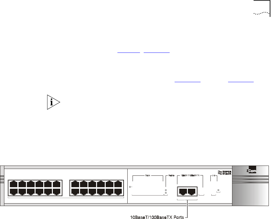
3Using RJ-45 connectors, connect the Ethernet port of the VCN AP to an
Ethernet switch 10BaseT port; refer to Figure 53. Refer to Figure 54 for
the network configuration.
Recommendation: Attach the downloading VCN AP to port
■26 in the VCN Services Switch 10.
■26 in the the SuperStack II Switch 1100.
■24 in the VCN Services Switch 100.
■24 in the SuperStack II Switch 3300.
Figure 53 The VCN Service Switch 10 Front Pane
green
flashing green
off
= enabled, link OK
= disabled, link OK
= link fail
3
3
4
4
6
6
5
5
7
7
8
8
9
9
10
10
11
11
12
12
1
1
2
23
5
1
4
7
6
8
2
13
13
14
14
15
15
16
16
17
17
18
18
19
19
20
20
21
21
22
22
23
23
24
24
VCN Services
Switch 10
3CV2010
Packet 25 26 Packet
25 26 Status
Packet
Status
Status
TCVR
Power/Self Test
6x 7x
18x 19x
1x
13x
12x
24x
25x 26x
60 CHAPTER 4: USING THE LOCAL MANAGEMENT ACCESS
Figure 54 Software Download Network Configuration
4In the VCN AP Main Menu (Figure 30) type 8, and press <Enter> for the
Software Download Menu.
A warning appears, followed by a prompt asking if you want to proceed
(Figure 55).
Figure 55 Remote software Download Warning and Prompt
5To proceed, type yes and press <Enter>; the Software Download Menu
(Figure 56) appears.
Ethernet
Regular
Phone
Cable
Ethernet
VCN Services Switch 10
Phone Line
PBX
VCN Access
Concentrator
Existing Phone
Lines
Punch-Down
Block
Punch-Down
Block
VCN
Access Point
JUHHQ
IODV KL QJ#JU H HQ
RII
#HQD EO HG /#OLQN#2.
#GLVD EO H G/#OL QN #2.
#OLQN #IDLO
6
6
7
7
9
9
8
8
:
:
;
;
<
<
43
43
44
44
45
45
4
4
5
5 6
8
4
7
:
9
;
5
46
46
47
47
48
48
49
49
4:
4:
4;
4;
4<
4<
53
53
54
54
55
55
56
56
57
57
6XSHU6WDFN#,,
6ZLWFK#6633
3C16980
3DFNHW
3DFNHW
6WDW XV
6WDW XV
3RZ H U26HO I#7HVW
9[:[
4;[4<[
4[
46[
45[
57[
3
24 Ports Concentrator
Software Download
VCN Access Point
Management
Computer
User
Computer
*************** WARNING *****************************************
*Choosing this menu will discontinue normal VCN AP operation. *
*VDSL line will be stopped. Reset board to renew VDSL connection*
*****************************************************************
Do you want to proceed (YES/[NO])? :

Remote Software Download 61
Figure 56 Software Download Menu
6To download software to LCs do as follows:
aCheck the VLAN IDs of the VCN AP and the VCN AC.
bTo change the VLAN ID of the AP to make it the same as the AC, type
6 in the Software Download Menu and press <Enter>. The following
dialog appears:
Current VLAN ID for downloading:
Please enter new VLAN ID (1 - 4094, 0 for none):
cEnter the AC VLAN ID and press <Enter>. The message appears:
Action has been done.
Software Download will not occur if the VCN AP is not in the same VLAN
as the VCN AC.
dIn the Software Download Menu, type 2 and press <Enter>. The LC
Downloading State Table appears (Figure 57).
Software Download Menu
----------------------
1. AP Version
2. Download LC
3. Download AP
4. LC Downloading State
5. AP Downloading State
6. Change the VLAN Id for Downloading
7. Reset Board
Please enter your choice:

62 CHAPTER 4: USING THE LOCAL MANAGEMENT ACCESS
Figure 57 The LC Downloading State Table
eAt the end of the LC Downloading State Table, do one of the
following:
■Type the number of an LC to receive the software download and press
<Enter>.
The downloading messages and the downloading results table appear
(Figure 58).
■Ty p e 0 and press <Enter> to download the software to all LC cards.
The downloading messages and the downloading results table appear
(Figure 58).
■Ty p e r and press <Enter> to cancel.
The VCN AP Software Download Menu (Figure 56) reappears.
LC downloading state table
------------------------------------------------------
| LC | Downloading || LC | Downloading |
| number | status || number | status |
------------------------------------------------------
| 1 | Not downloaded || 13 | Not downloaded |
| 2 | Not downloaded || 14 | Not downloaded |
| 3 | Not downloaded || 15 | Not downloaded |
| 4 | Not downloaded || 16 | Not downloaded |
| 5 | Not downloaded || 17 | Not downloaded |
| 6 | Not downloaded || 18 | Not downloaded |
| 7 | Not downloaded || 19 | Not downloaded |
| 8 | Not downloaded || 20 | Not downloaded |
| 9 | Not downloaded || 21 | Not downloaded |
| 10 | Not downloaded || 22 | Not downloaded |
| 11 | Not downloaded || 23 | Not downloaded |
| 12 | Not downloaded || 24 | Not downloaded |
------------------------------------------------------
Enter LC number (1 - 24, 0 for all, R for return):

Remote Software Download 63
Figure 58 LC Downloading Results
Begin sending version...
Sending version complete
Waiting for acknowledge...
Downloading complete.
Downloading complete. See results in the table:
------------------------------------------------------
| LC | Downloading || LC | Downloading |
| number | status || number | status |
------------------------------------------------------
| 1 | Successful || 13 | Successful |
| 2 | Successful || 14 | Successful |
| 3 | Successful || 15 | Successful |
| 4 | Successful || 16 | Successful |
| 5 | Successful || 17 | Successful |
| 6 | Successful || 18 | Successful |
| 7 | Successful || 19 | Successful |
| 8 | Successful || 20 | Successful |
| 9 | Successful || 21 | Successful |
| 10 | Successful || 22 | Successful |
| 11 | Successful || 23 | Successful |
| 12 | Successful || 24 | Successful |
------------------------------------------------------
Press ENTER to continue ...

64 CHAPTER 4: USING THE LOCAL MANAGEMENT ACCESS
Downloading Software to VCN APs:
To download software to VCN APs do as follows:
1Perform step 1 through step 5 above.
2Check the VLAN IDs of the downloading VCN AP and the receiving VCN
APs.
3To change the VLAN ID of the AP to make it the same as the receiving
VCN APs, type 6 in the VCN AP Software Download Menu and press
<Enter>. The following dialog appears:
Current VLAN ID for downloading:
Please enter new VLAN ID (1 - 4094, 0 for none):
4Enter the AP VLAN ID and press <Enter>. The message appears:
Action has been done.
Software Download will not occur if the downloading VCN AP is not in
the same VLAN as the receiving VCN APs.
5In the Software Download Menu type 3 and press <Enter>. The AP
Downloading State Table appears (Figure 59).

Remote Software Download 65
Figure 59 AP Downloading State Table
6At the end of the AP Downloading State Table, do one of the following:
■Type the number of VCN AP to receive the software download and
press <Enter>.
The downloading messages and the downloading results table appear
(Figure 60).
■Ty p e 0 to download software to all VCN AP cards and press <Enter>.
The downloading messages and the downloading results table appear
(Figure 60).
■Ty p e r and press <Enter> to cancel.
The VCN AP Software Download Menu (Figure 56) reappears.
AP downloading state table
------------------------------------------------------
| AP | Downloading || AP | Downloading |
| number | status || number | status |
------------------------------------------------------
| 1 | Not downloaded || 13 | Not downloaded |
| 2 | Not downloaded || 14 | Not downloaded |
| 3 | Not downloaded || 15 | Not downloaded |
| 4 | Not downloaded || 16 | Not downloaded |
| 5 | Not downloaded || 17 | Not downloaded |
| 6 | Not downloaded || 18 | Not downloaded |
| 7 | Not downloaded || 19 | Not downloaded |
| 8 | Not downloaded || 20 | Not downloaded |
| 9 | Not downloaded || 21 | Not downloaded |
| 10 | Not downloaded || 22 | Not downloaded |
| 11 | Not downloaded || 23 | Not downloaded |
| 12 | Not downloaded || 24 | Not downloaded |
------------------------------------------------------
Enter AP number (1 - 24, 0 for all, R for return):

66 CHAPTER 4: USING THE LOCAL MANAGEMENT ACCESS
Figure 60 AP Downloading Results
Check Software Download for the LC Cards:
To check the software download results in the LC cards, type 4 and press
<Enter> in the Software Download Menu. The LC Downloading State
Table appears.
Check Software Download for the VCN APs:
To check the software download results of the VCN APs, type 5 and press
<Enter> in the Software Download Menu. The VCN AP Downloading
State appears.
Begin sending version...
Sending version complete
Waiting for acknowledge...
Downloading complete.
Downloading complete. See results in the table:
------------------------------------------------------
| AP | Downloading || AP | Downloading |
| number | status || number | status |
------------------------------------------------------
| 1 | Successful || 13 | Successful |
| 2 | Successful || 14 | Failed |
| 3 | Successful || 15 | Failed |
| 4 | Successful || 16 | Failed |
| 5 | Failed || 17 | Failed |
| 6 | Failed || 18 | Successful |
| 7 | Failed || 19 | Failed |
| 8 | Failed || 20 | Successful |
| 9 | Failed || 21 | Successful |
| 10 | Failed || 22 | Successful |
| 11 | Failed || 23 | Successful |
| 12 | Failed || 24 | Successful |
------------------------------------------------------
Press ENTER to continue ...

Remote Software Download 67
Solving Problems in
Remote Software
Download
If the LC Downloading Results in Figure 58 show download failed for one
or more Line Cards or the AP Downloading Results in Figure 60 show
download failed for one or more APs, follow the procedures this section
to solve the problems.
Download Failed for all LCs and all VCN APs
Check the following:
■Downloading VCN AP software version.
If the version is not 3.5 or later, locally download version 3.5 or the
later version to the VCN AP. Refer to Appendix C, Loading Software
Through Local Access.
■Downloading VCN AP connections to the network.
■Check the configuration of your switch and perform the following
step:
Run the ConfApp program on the switch or perform manual
configuration according to Visitor and Community Based Networking
Access Concentrator Service Manual, the section Configuring the
Ethernet Switch for the VCN Access Concentrator.
Perform remote software download again.
Download Failed for One or More Line Cards but not All
Check the following:
■Software version of the failed LCs.
If the version is not 3.5 or later, locally download the current software.
Refer to the Visitor and Community Based Networking Access
Concentrator Service Manual. Remote software download need not
be performed after this step.
■Check the physical path between the downloading VCN AP and the
VCN AC.
■Check the configuration of your switch and perform the following
steps:
Run the ConfApp program on the switch or perform manual
configuration according to Visitor and Community Based Networking
Access Concentrator Service Manual, the section Configuring the
Ethernet Switch for the VCN Access Concentrator.
Perform remote software download again.

68 CHAPTER 4: USING THE LOCAL MANAGEMENT ACCESS
Download Failed for One or More VCN APs but not All
Check the following:
■AP software version of the failed APs.
If the version is not 3.0 or later, locally download the current software
version to the VCN AP. Refer to Appendix C, Loading Software
Through Local Access. Remote software download need not be
performed after this step.
■Check the physical path between the downloading VCN AP and the
VCN APs.
■Check the VDSL connection between the failed APs and the VCN AC.
■Check the configuration of your switch and perform the following
steps:
Run the ConfApp program on the switch or perform manual
configuration according to Chapter 2, Using the Local Management
Access, section Configuring the Ethernet Switch for the VCN Access
Concentrator.
Perform remote software download again.

ATROUBLESHOOTING
This appendix explains how to identify and correct problems, and how to
perform related diagnostic tasks.
If you have problems that are not addressed in this chapter, contact
3Com Technical Support or your service person. Refer to Appendix F for
technical support information.
Power-on Self Test
(POST)
When the VCN Access Point is plugged-in, the VCN AP immediately starts
the power-on self test (POST) sequence as indicated by the power LED
flashing in green. If the VCN AP is not powered, the power LED remains
OFF. Check the power connections and the ac/dc adapter.
The power-on self test verifies that every component of the VCN AP is
fully functional. The power-on self test lasts for 30 seconds at the most,
during which time it is orange. If the power-on self test is successfully
completed, the power LED turns green. If the power-on self test detected
a VCN AP failure, the power LED remains orange. In this case, contact
3Com technical support; refer to Appendix F, Technical Support.
Use the front panel LEDs to determine each port’s status:
Ta b l e 7 Determining VCN AP Status During POST
State Ethernet Line Power Notes
Off - - Off VCN AP is not connected to a
power source or failed.
Power-on - - Orange Test is in progress
Power-on - - Off VCN AP failed
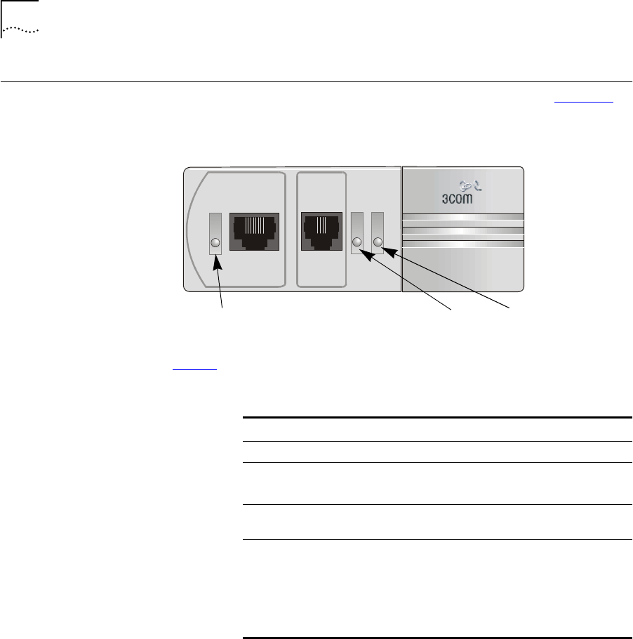
70 APPENDIX A: TROUBLESHOOTING
Using Front Panel
LEDs to Solve
Problems
This section describes the use of the LEDs to solve problems. Figure 61
displays the VCN AP LED indicators.
Figure 61 The VCN AP Unit Front View
Ta b l e 8 describes the LEDs.
Ta b l e 8 The VCN AP LEDs
LED State Indicates
Ethernet Green VCN AP connected a PC.
Line OFF VCN AP is not connected to the line.
Green VCN AP connected to the VCN AC.
Flashing
Green
Data transmission to or from the VCN AC.
Power OFF VCN AP is not powered.
Orange First 30 seconds after connection to the power
main, power-on-self-test (POST) in progress.
After 30 seconds, POST failed.
Green The VCN AP is functioning.
Fax-ModemETHERNET
Line
Power
Ethernet
LED Power LED
Line LED

Using Front Panel LEDs to Solve Problems 71
Use the front panel LEDs to determine the VCN AP status after POST.
Ta b l e 9 provides detailed information summarized in Ta b l e 1 0 .
Ta b l e 9 Determining VCN AP status from the LED Indications after POST
State Ethernet Line Power Notes
OFF OFF OFF OFF VCN AP is not
connected to a power
source.
Power-on ON if user
data cable is
connected.
OFF if user
cable is not
connected.
OFF if the line is
not connected.
If the line is
connected, it is
steady green for
2 minutes after
POST; After 2
minutes it can
be steady green
if there is no
traffic, and
flashing green if
there is traffic.
The above states
are normal.
If the LED is not
steady green
during the first 2
minutes after
POST, there is a
communication
problem.
Any other
appearance
after the first 2
minutes
indicates the
presence of a
problem.
During
POST, the
LED is
orange. If
the LED
remains
orange after
30 seconds,
the VCN AP
is faulty and
should be
replaced.
If the Power LED
remains orange after
30 seconds (POST),
the technician uses
the RS-232 LMI
connector and
terminal emulation to
view the VCN AP
diagnostic messages
on his terminal screen.
Voice Call Not
Applicable
(NA)
NA NA Connection to power
is not needed to make
a voice call.
An Ethernet
connection is not
required.

72 APPENDIX A: TROUBLESHOOTING
Fax/Modem
Call
Not
Applicable
(NA)
NA NA No power is needed to
make a fax/modem
call.
An Ethernet
connection is not
required.
Data Transfer
from PC
ON Flashing in
green
ON Indicates data is
passing through the
VCN AP.
There is a
valid
connection
between
the VCN AP
and the user
PC.
Data is passing
between the
user PC and the
network
through the
VCN AP.
Ta b l e 9 Determining VCN AP status from the LED Indications after POST
State Ethernet Line Power Notes

Using Front Panel LEDs to Solve Problems 73
VCN AP
Failure
Indicated
OFF after
connection:
Possible
causes:
■faulty
power
adapter
■problem
in the
VCN AP
Replace ac/dc adapter
and try again. If the
problem is eliminated,
the problem was the
adapter. If not, the
problem is in the VCN
AP; replace it and
send it to 3Com.
OFF and the
user data
cable is
connected.
ON (green) One of the items
below failed:
■user data cable
■user PC NIC
■VCN AP
Try replacing each of
the first 2 items. If the
problem is not
eliminated, the
problem is in the VCN
AP; replace it and
send it to 3Com.
The Line LED
does not turn
steady green
during 2
minutes after
POST
Possible causes are:
■no connection
■wiring
■VCN AC
■punch down
block/patch panel
Power the VCN AP
OFF, then ON. If the
VCN AP starts
properly, the problem
is solved. If not,
replace it and send it
to 3Com.
Ta b l e 9 Determining VCN AP status from the LED Indications after POST
State Ethernet Line Power Notes

74 APPENDIX A: TROUBLESHOOTING
Using a PC Terminal
Emulator to Solve
Problems
Refer to Appendix E for setting the parameters of a terminal emulation
program. Then refer to Chapter 4 Using the Local Management Accessfor
connecting the management PC to the VCN AP to operate the
management menus.
Table 10 Summary of VCN AP LED Indications after POST
Problem Solution
The power LED
remains OFF after
power connection
Check the power connections and the ac/dc adapter. Plug in
the power cable if necessary.
The power LED
remains orange
longer than 30
seconds.
A hardware fault has been detected in the VCN AP.
Power the VCN AP OFF and then ON. If the problem persists,
contact 3Com.
The Line LED is not
green.
Check the line connection. If the line connections are
appropriate, the VCN AP is not functioning.
Power the VCN AP OFF and then ON. If the problem persists,
contact 3Com.
The Ethernet LED is
OFF.
Check the Ethernet cable. The problem could be in your NIC
or in the VCN AP.
Power the VCN AP OFF and then ON. If the problem persists,
contact 3Com.

Using a PC Terminal Emulator to Solve Problems 75
Ethernet Traffic
Counts
The normal frame counters indicate traffic between the VCN AP and user
PC. Some errored frame counters indicate fatal errors, requiring
replacement of the VCN AP, Ethernet cable or the user’s PC Network
Interface Card (NIC).
The following table depicts normal count indications of the Ethernet
traffic counters and probable causes for abnormal indications.
HDLC Traffic Counts Normal frame counts indicate traffic between the VCN AP and the VCN
AC. Some errored frame counters indicate fatal errors, requiring
replacement of the VCN AP (failure between the analog front-end section
and the CPU section), or handling of environmental noise over the line.
Table 11 Ethernet Traffic Counters
Counter Counts the Frames Normal Count
Abnormal Count
Indicates
Tx frame Sent via the Ethernet
Port.
Increases as traffic is
generated
No data transmitted;
hardware problem:
■VCN AP Tx channel
■User Ethernet cable
■No VCN AP
connection
Rx frame Received via the
Ethernet port.
Increases as traffic is
generated
No data received;
hardware problem:
■VCN AP Rx channel
■User Ethernet cable
■No VCN AP
connection
Rx collision The VCN AP was
unable to receive
due to collisions on
the line
Zero or steady. For
non-zero count,
reset the counter
and wait a
reasonable period
of time to check for
no significant
increase.
VCN AP port hardware
failure.
CRC error,
overrun,
Alignment
error, frame
too long,
frame too
short
Containing receive
fatal errors.
Zero Hardware failure: VCN
AP, Ethernet cable or PC
NIC

76 APPENDIX A: TROUBLESHOOTING
The following table depicts normal counter indications and probable
causes of abnormal counter indications.
Summary of
Abnormal Indications
from Traffic Counts
The following provides a quick reference to problem identification by
using frame counts:
Error Messages There are two types of error messages that appear on the management
terminal screen:
■Advisory
Table 12 HDLC Traffic Count Indicators
Counter Counts the Frames Normal Count
Abnormal count
indicates
Tx frames Sent via the
telephone line
High No transmit data
Rx frames Received via
telephone line
High No receive data
Tx discarded The VCN AP was
unable to send
Low VCN AP software
failure
Rx discarded The VCN AP was
unable to receive
Low, unless the
traffic is
bi-directional
VCN AP software
limitation
Overrun, Not
mine, DPLL
error, Abort
sequence, Non
aligned, CRC
error, Frame too
long
Containing Receive
fatal errors
Zero/low VCN AP hardware
failure if abnormal
count is growing
significantly by the
minute
Table 13 Summary of Problems Indicated by Counts of Errored Frames
Problem Solution
The following Ethernet traffic counters are
growing significantly: CRC error, Overrun,
Alignment error, Frame too long, or Frame too
short.
Replace in this order: the VCN AP,
or the Ethernet cable, or the PC
NIC.
The following HDLC traffic counters are
growing significantly: Tx error, Overrun, Not
mine, DPLL error, Abort sequence,
Nonaligned, CRC error, Frame too long.
Replace the VCN AP.

Using a PC Terminal Emulator to Solve Problems 77
The only error message of this type is Wrong entry! It appears when
the user enters the wrong response to a menu. The user solves the
problem by re-entering his response.
When a user disconnects the management terminal from the LMI port
and later reconnects, the LMI menu system stays in the same state and
expects the same user input after reconnect. During reconnect the user
may press the wrong sequence of keys and cause Wrong entry! to be
displayed on the screen. Type 0 and press <Enter> a few times until the
desired menu appears.
■Fatal
Almost all error messages that do appear are fatal. Contact Technical
Support when an error message, except for Wrong entry!, appears. The
most common fatal error messages are listed in Ta b l e 1 4 .
Boot-up and initialization are processes that occur when the VCN AP is
reset. Reset occurs when the user selects Reset board from the menu
system.
Table 14 Fatal Error Messages
Error message Significance User Action
FATAL ERROR: SDRAM test
failed!
Hardware error during
boot-up
Contact Technical Support.
FATAL ERROR: failed FLASH
access!
Hardware error during
boot-up
Contact Technical Support.
Ethernet selftest failed! Hardware error during
initialization
Contact Technical Support.
HDLC selftest failed! Hardware error during
initialization
Contact Technical Support.
I2C selftest failed! Hardware error during
initialization
Contact Technical Support.
DRAM data bus test fail! Hardware error Contact Technical Support.
DRAM address bus test fail! Hardware error Contact Technical Support.

78 APPENDIX A: TROUBLESHOOTING

BPRODUCT SPECIFICATION
Line Data Rate Up to 10 Mbps, symmetric
Range up to 4000 ft
Cabling CAT1 to CAT5
Voice Dial Tone, Toll Quality, PBX features support
Power requirements
VCN AP Mains 90-260 ac, 47-63 Hz, 6 Watt maximum
ac/dc adapter 3.3 Vdc /1.5 A, 5 Vdc /150 mA, -5 Vdc /50 mA
Standards Compliance
Safety UL 1950
C-UL, CSA22.#950
EN60950
IEC950
TS-001
EMC FCC Part 15 Class B
AS/NZS 3548
VCCI Class B
CISPR22 Class B
CAN/CSA-CISPR22 Class B
EN 55022 Class B, Amendment A1, Amendment A2
EN 55024
IEC 61000-4-2 through 61000-4-6, IEC 61000-4-11
Ethernet IEEE 802.3
Management interface 1 RS-232 port
Environmental
Operating Temperature 0°- 50°C
Relative humidity 95% non-condensing

80 APPENDIX B: PRODUCT SPECIFICATION

CLOADING SOFTWARE THROUGH
LOCAL ACCESS
This appendix describes how to load a new software release into the VCN
AP through the LMA port.
Loading software requires using a PC in terminal emulation mode. Refer
to Appendix E Terminal Emulation Settings for a description of terminal
emulation procedures.
To load software into an VCN AP, perform the following steps:
1Attach your terminal emulating PC to the LMA port on the VCN AP.
2Press any key to view the VCN AP Main Menu on the terminal screen. If
another menu appears, press 0 (zero) and ENTER repeatedly until the
Main Menu appears.
3In the Main Menu (Figure 62) type 3, and press ENTER.

82 APPENDIX C: LOADING SOFTWARE THROUGH LOCAL ACCESS
Figure 62 VCN AP Main Menu
The Management Menu appears:
Figure 63 VCN AP Management Menu
4In the Management Menu type 5 to reset the VCN AP. The dialog in
Figure 64 appears:
Figure 64 Confirm Reset Board
:
VCN AP Main Menu
------------------
1. VCN AP Version
2. Debug Menu
3. Management Menu
4. VDSL control
5. Test control
6. Flash actions
7. VCN AP Configuration
8. Software Download Menu
0. Exit
Please enter your choice:
Management Menu
-----------------
1. Ethernet menu
2. HDLC menu
3. Tasks info menu
4. Reset all counters
5. Reset board
0. Return to main menu
Please enter your choice:
This action will reset the whole board!
Do you want to proceed (Y/[N])? :

83
5Ty p e Y to reset. The screen in Figure 65 appears:
Figure 65 Software Download Option
6Ty p e S; the downloading message appears (Figure 71).
The option of F in the Software Download Menu (Figure 65), is the
default; if the Software Download Menu displays for 5 seconds,
execution from the flash automatically begins. The option of D is for
debug purposes only and should only be carried out by system
developers. Option C is for entering the MAC address. This is normally
performed in the factory.
Figure 66 Software Downloading Message
********************************************************
3Com NCD. (C)
10Base-S Boot loader V2.00
Date: Jun 15 1999, Time: 16:13:31
CPE modem Operation Mode Selector.
Enter:
S - for Serial loading OR
D - for Debug operation OR
F - for SW execution from the Flash OR
C - for MAC address programming.
********************************************************
******************************
Load procedure via Serial Line.
******************************
Waiting for downloading...
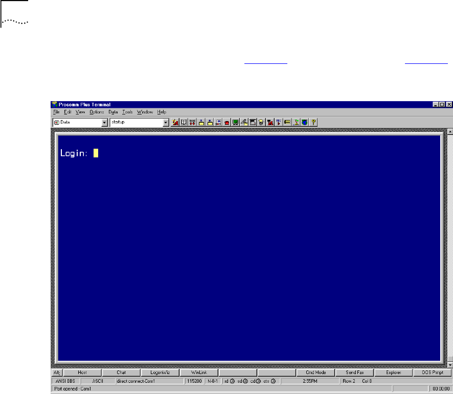
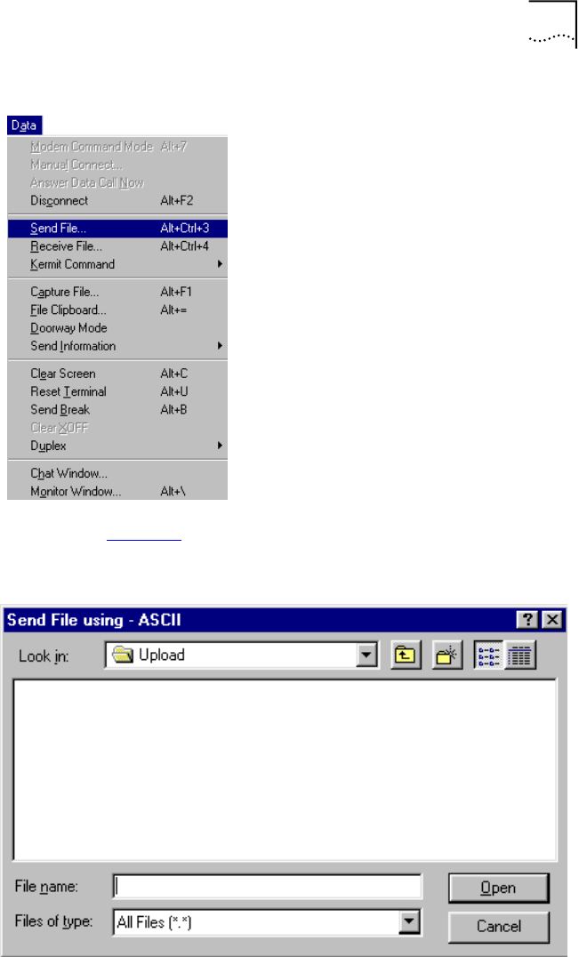
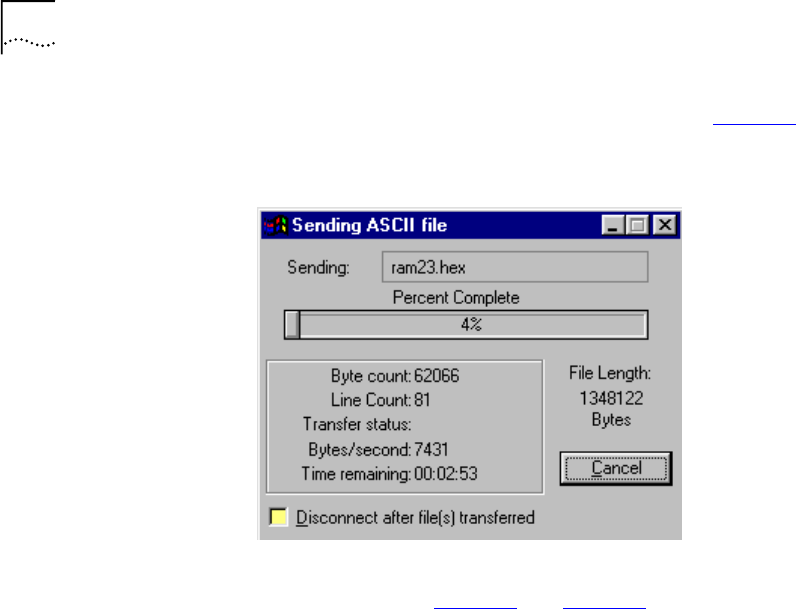

87
Figure 71 Software Downloading Message
Start saving to the FLASH!
Sector passed number-12
Sector passed number-13
Sector passed number-14
Sector passed number-15
Sector passed number-16
Sector passed number-17
Sector passed number-18
Sector passed number-19
Sector passed number-20
Sector passed number-21
Sector passed number-22
Sector passed number-23
Flash erased OK!
Storage2 has been erased!
Application buffer address - 99e8
Last write address - 2940004
Last write data - f
Last written data - f
Data counter - 1
Indicator has been written!
Application buffer address - 160000
Last write address - 2940008
Last write data - 0
Last written data - 0
Data counter - 393211
SW image has been saved!
Application buffer address - 66d0
Last write address - 2940000
Last write data - 55aa
Last written data - 55aa
Data counter - 1
Signature has been written!
The SW version has been saved to the FLASH!
SW image is being executed!!!
*****************************
Start executing main!
Watchdog initialized OK !

88 APPENDIX C: LOADING SOFTWARE THROUGH LOCAL ACCESS
Figure 72 Self-Test Messages
The Login prompt appears.
After the software download, the unit starts to execute the software from
the flash memory.
If, instead of the messages in Figure 71, one of the following messages
appear, the software load failed:
■Flash Error
■SW image validation failed
Action: Try to load the software again. If the problem persists, replace
the VCN AP.
HDLC selftest passed!
Ethernet selftest passed!
I2C selftest passed!
VDSL selftest passed!
MNG task created!
MNG task started!
LED task created!
LED task started!
DWN task created!
DWN task started!
LMA task created
LMA task started
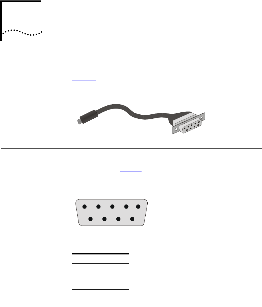
DPIN ASSIGNMENTS FOR LMA
CABLE
This appendix describes the pin assignments for the LMA cable, see
Figure 73. The cable is used in an RS-232 connection.
Figure 73 Local Management Access Cable
Connector for Local
Management
Te r m i n a l
The connector for the local management (LM) terminal emulating
computer is displayed in Figure 74. The connector consists of a DB 9-pin
female connector. Ta b l e 1 5 describes the pin assignments.
Figure 74 DB 9-Pin Female Connector
Table 15 LM Terminal Connector Pin Assignment
Pin No. Assignment
1Not used
2Tx
3Rx
4Not used
5Ground (GND)
1
3
4
52
7
896

90 APPENDIX D: PIN ASSIGNMENTS FOR LMA CABLE
Connector for the
LMA Port of the
VCN AP
The connector for the LMA port of the VCN AP is described below. The
connector consists of a MiniDIN 4-pin male connector, see Figure 75.
Ta b l e 1 6 describes the pin assignments.
Figure 75 MiniDIN 4-Pin Connector Pin Numbering
6Not used
7Not used
8Not used
9Not used
Table 15 LM Terminal Connector Pin Assignment
Pin No. Assignment
Table 16 LMA Port Connector Pin Assignment
Pin No. Assignment
1Tx
2Rx
3GND
4GND
1
3
2
4
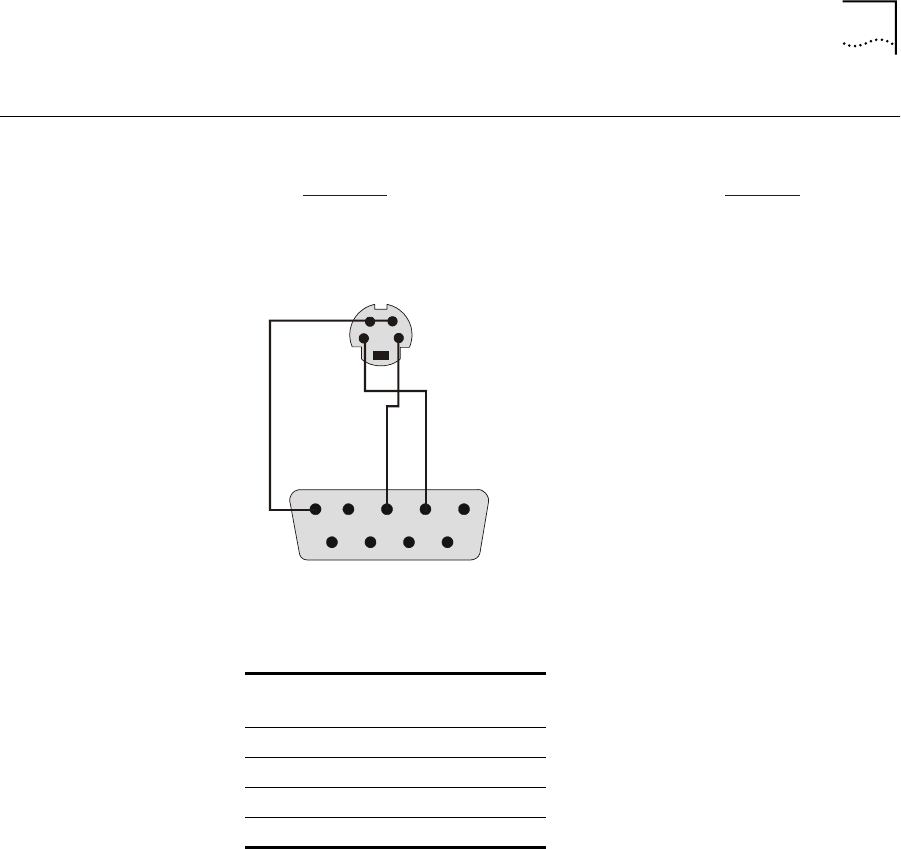
Local Management Cable Wiring 91
Local Management
Cable Wiring
This section describes the connection of the pins in the LM terminal
connector to the pins in the VCN AP LMA port connector within the
cable. Figure 76 depicts the connections in the cable. Ta b l e 1 7 lists the
pin connections for the wires in the cable. The Tx and Rx directions relate
to the VCN AP, not the LM terminal.
Figure 76 LM Cable Wiring
Table 17 LM Cable Connections
MiniDIN
Pin No.
DB-9
Pin No. Assignment
1 2 Tx
2 3 Rx
3 5 GND
4 5 GND
1
32
4
53421
98 6
6
7
6

92 APPENDIX D: PIN ASSIGNMENTS FOR LMA CABLE

ET
ERMINAL EMULATION SETTINGS
This appendix describes the terminal emulation settings for Procomm
Plus. Procomm Plus is presented here as an example of a terminal
emulation program; you can use another program with similar settings.
Defining the
Terminal Emulation
Settings
To define the terminal emulation settings:
1Start the Procomm Plus terminal emulator through one of the procedures
below:
■Double-click the Procomm Plus shortcut if it appears on the PC
Desktop.
or
■Select Start > Programs > Procomm Plus.
The Procomm Plus Terminal screen in Figure 77 appears.
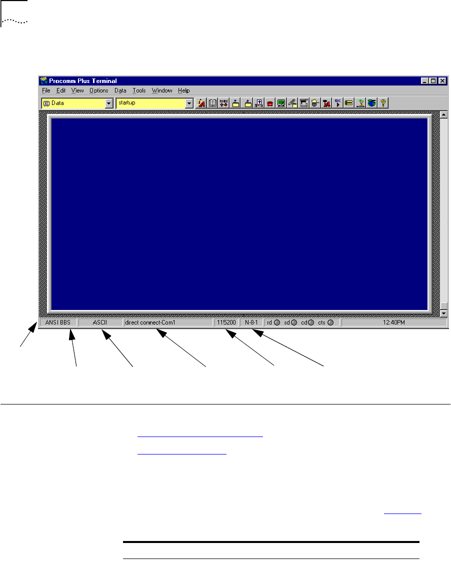
94 APPENDIX E: TERMINAL EMULATION SETTINGS
Figure 77 Procomm Plus Terminal Screen
Establishing
Terminal Settings
Terminal settings can be established in one of two ways:
■Using the Configuration Bar
■Using the Menu Bar
Using the
Configuration Bar
To establish terminal settings using the configuration bar:
1From the Configuration Bar, establish the settings listed in Tab l e 1 8 .
Data Code PC Communication
Port
Bits per
Second
Terminal type
Configuration
Bar ASCII
parameters
Table 18 Procomm Plus Settings
No From Left Function Settings
1Type of Terminal ANSI BBS
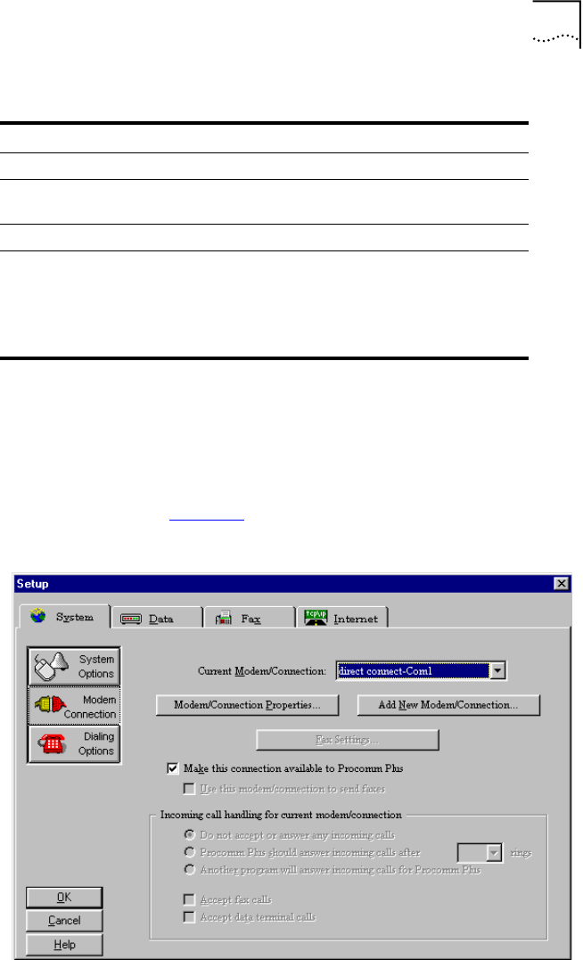
Establishing Terminal Settings 95
2If necessary, click the appropriate button to display a list of all possible
settings and select the required settings.
Using the Menu Bar To establish terminal settings using the menu bar:
1Select Options > System Options > Modem Connection. The Setup
window as shown in Figure 78 opens.
Figure 78 Procomm Setup Window
2Select System Tab.
2Data Code ASCII
3PC serial communication
port
COMx
4Bits per second 115200
5ASCII parameters 8-N-1:
8 bits
No parity
1 stop bit
Table 18 Procomm Plus Settings (continued)
No From Left Function Settings
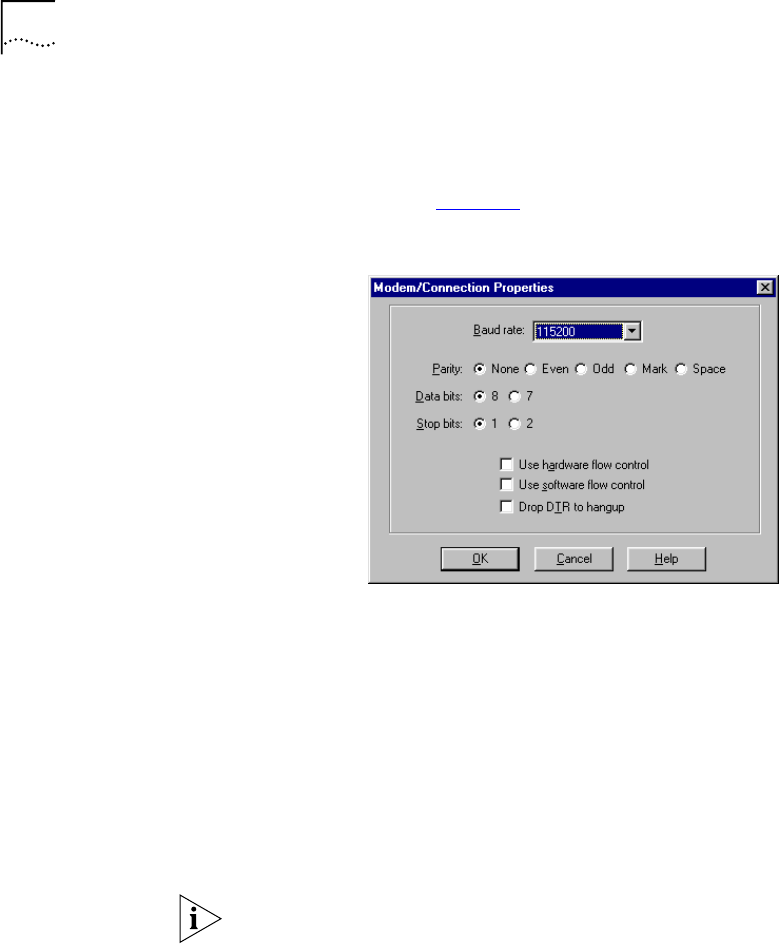
96 APPENDIX E: TERMINAL EMULATION SETTINGS
3From the Current Modem/Connection window, select direct
connect-ComX, where X represents the number of your com port.
4Click Modem/Connection Properties. The Modem/Connection Properties
window as shown in Figure 79 opens.
Figure 79 Connection Properties Window
5From the Baud rate window, select 115200.
6Set the following parameters:
■Parity: None.
■Data bits: 8.
■Stop bits: 1.
■Flow control
■Use hardware flow control is the default.
■Use software flow control
Set Use software flow control if your computer works better with
software flow control.
7Click OK.
8Click OK.
Your terminal is now ready for local management functions and for
downloading software.

FT
ECHNICAL SUPPORT
3Com provides easy access to technical support information through a
variety of services. This appendix describes these services.
Information contained in this appendix is correct at time of publication. For
the most recent information, 3Com recommends that you access the
3Com Corporation World Wide Web site.
Online Technical
Services
3Com offers worldwide product support 24 hours a day, 7 days a week,
through the following online systems:
■World Wide Web Site
■3Com Knowledgebase Web Services
■3Com FTP Site
■3Com Bulletin Board Service
■3Com Facts Automated Fax Service
World Wide Web Site To access the latest networking information on the 3Com Corporation
World Wide Web site, enter this URL into your Internet browser:
http://www.3com.com/
This service provides access to online support information such as technical
documentation and software, as well as support options that range from
technical education to maintenance and professional services.
3Com
Knowledgebase Web
Services
This interactive tool contains technical product information compiled by
3Com expert technical engineers around the globe. Located on the World
Wide Web at http://knowledgebase.3com.com, this service gives all
3Com customers and partners complementary, round-the-clock access to
technical information on most 3Com products.

98 APPENDIX F: TECHNICAL SUPPORT
3Com FTP Site Download drivers, patches, software, and MIBs across the Internet from the
3Com public FTP site. This service is available 24 hours a day, 7 days a week.
To connect to the 3Com FTP site, enter the following information into
your FTP client:
■Hostname: ftp.3com.com
■Username: anonymous
■Password: <your Internet e-mail address>
You do not need a user name and password with Web browser software
such as Netscape Navigator and Internet Explorer.
3Com Bulletin Board
Service
The 3Com BBS contains patches, software, and drivers for 3Com products.
This service is available through analog modem or digital modem (ISDN)
24 hours a day, 7 days a week.
Access by Analog Modem
To reach the service by modem, set your modem to 8 data bits, no parity,
and 1 stop bit. Call the telephone number nearest you:
Country Data Rate Telephone Number
Australia Up to 14,400 bps 61 2 9955 2073
Brazil Up to 28,800 bps 55 11 5181 9666
France Up to 14,400 bps 33 1 6986 6954
Germany Up to 28,800 bps 4989 62732 188
Hong Kong Up to 14,400 bps 852 2537 5601
Italy Up to 14,400 bps 39 2 27300680
Japan Up to 14,400 bps 81 3 5977 7977
Mexico Up to 28,800 bps 52 5 520 7835
P.R. of China Up to 14,400 bps 86 10 684 92351
Taiwan, R.O.C. Up to 14,400 bps 886 2 377 5840
U.K. Up to 28,800 bps 44 1442 438278
U.S.A. Up to 53,333 bps 1 847 262 6000

Support from Your Network Supplier 99
Access by Digital Modem
ISDN users can dial in to the 3Com BBS using a digital modem for fast
access up to 64 Kbps. To access the 3Com BBS using ISDN, call the
following number:
1 847 262 6000
3Com Facts
Automated Fax
Service
The 3Com Facts automated fax service provides technical articles,
diagrams, and troubleshooting instructions on 3Com products 24 hours a
day, 7 days a week.
Call 3Com Facts using your Touch-Tone telephone:
1 408 727 7021
Support from Your
Network Supplier
If you require additional assistance, contact your network supplier. Many
suppliers are authorized 3Com service partners who are qualified to
provide a variety of services, including network planning, installation,
hardware maintenance, application training, and support services.
When you contact your network supplier for assistance, have the
following information ready:
■Product model name, part number, and serial number
■A list of system hardware and software, including revision levels
■Diagnostic error messages
■Details about recent configuration changes, if applicable
If you are unable to contact your network supplier, see the following
section on how to contact 3Com.
Support from 3Com If you are unable to obtain assistance from the 3Com online technical
resources or from your network supplier, 3Com offers technical telephone
support services. To find out more about your support options, call the
3Com technical telephone support phone number at the location nearest
you.

100 APPENDIX F: TECHNICAL SUPPORT
When you contact 3Com for assistance, have the following information
ready:
■Product model name, part number, and serial number
■A list of system hardware and software, including revision levels
■Diagnostic error messages
■Details about recent configuration changes, if applicable
Here is a list of worldwide technical telephone support numbers:
Country Telephone Number Country Telephone Number
Asia, Pacific Rim
Australia
Hong Kong
India
Indonesia
Japan
Malaysia
New Zealand
Pakistan
Philippines
1 800 678 515
800 933 486
+61 2 9937 5085
001 800 61 009
0031 61 6439
1800 801 777
0800 446 398
+61 2 9937 5085
1235 61 266 2602
P.R. of China
Singapore
S. Korea
From anywhere in S. Korea:
From Seoul:
Taiwan, R.O.C.
Thailand
10800 61 00137 or
021 6350 1590
800 6161 463
00798 611 2230
(0)2 3455 6455
0080 611 261
001 800 611 2000
Europe
From anywhere in Europe, call: +31 (0)30 6029900 phone
+31 (0)30 6029999 fax
Europe, South Africa, and Middle East
From the following countries, you may use the toll-free numbers:
Austria
Belgium
Denmark
Finland
France
Germany
Hungary
Ireland
Israel
Italy
0800 297468
0800 71429
800 17309
0800 113153
0800 917959
0800 1821502
00800 12813
1800 553117
1800 9453794
1678 79489
Netherlands
Norway
Poland
Portugal
South Africa
Spain
Sweden
Switzerland
U.K.
0800 0227788
800 11376
00800 3111206
0800 831416
0800 995014
900 983125
020 795482
0800 55 3072
0800 966197
Latin America
Argentina
Brazil
Chile
Colombia
AT&T +800 666 5065
0800 13 3266
1230 020 0645
98012 2127
Mexico
Peru
Puerto Rico
Venezuela
01 800 CARE (01 800 2273)
AT&T +800 666 5065
800 666 5065
AT&T +800 666 5065
North America 1 800 NET 3Com
(1 800 638 3266)
Enterprise Customers:
1 800 876-3266

Returning Products for Repair 101
Returning Products
for Repair
Before you send a product directly to 3Com for repair, you must first
obtain an authorization number. Products sent to 3Com without
authorization numbers will be returned to the sender unopened, at the
sender’s expense.
To obtain an authorization number, call or fax:
Country Telephone Number Fax Number
Asia, Pacific Rim + 65 543 6500 + 65 543 6348
Europe, South Africa, and
Middle East
+ 31 30 6029900 + 31 30 6029999
Latin America 1 408 326 2927 1 408 326 3355
From the following countries, you may call the toll-free numbers; select option 2 and
then option 2:
Austria
Belgium
Denmark
Finland
France
Germany
Hungary
Ireland
Israel
Italy
Netherlands
Norway
Poland
Portugal
South Africa
Spain
Sweden
Switzerland
U.K.
0800 297468
0800 71429
800 17309
0800 113153
0800 917959
0800 1821502
00800 12813
1800553117
1800 9453794
1678 79489
0800 0227788
800 11376
00800 3111206
0800 831416
0800 995014
900 983125
020 795482
0800 55 3072
0800 966197
U.S.A. and Canada 1 800 NET 3Com
(1 800 638 3266)
Enterprise Customers:
1 800 876 3266
1 408 326 7120
(not toll-free)

INDEX
Numbers
3Com bulletin board service (3Com BBS) 98
3Com Knowledgebase Web Services 97
3Com URL 97
3ComFacts 99
A
Abnormal Indications from Traffic Counts 76
AC/DC adapter 33, 69
account number 36
applications 12
B
bulletin board service 98
C
Calls 35
conventions
notice icons, About This Guide 3
text, About This Guide 4
D
DB 9-pin connector 89
default VCNAP operation 83
E
electric connection 33
Ethernet card 11
Ethernet over VDSL 58
Ethernet port 11, 36
Ethernet status 44
Ethernet traffic count 76
Ethernet traffic counts 43
F
fax service (3ComFacts) 99
faxes, sending 36
flash memory 86
front panel LEDs 70
G
guide is intended for 3
H
hardware version 42
HDLC 48
status 49
traffic counters 48
HDLC traffic count 76
I
intranet 12
ISP 34, 36
L
LAN
Local Area Network 12
LC Downloading State Table 61
Line connector 16
LMA
connector cable 37
load 81
loading new software locally 81
Loading software 81
loading software 83
local management cable 89
local management cable wires 91
Local Management port 57
LMA port 38
local management terminal 89
local software download 81
local software load fail 88
log-in procedure 36
M
Main Menu 42

104 INDEX
Management Menu 42
MIBs 98
MiniDIN 4-pin connector 38
MiniDIN connector 90
monitoring 37
mounting
VCNAP on the wall 23
multiple dwelling units 11
multiple tenant units 11
N
network supplier support 99
O
online technical services 97
Operation instructions 35
P
paper template 23
password 36
POTS 9, 10
power connector 16
Power-on Self Test 69
PSTN 34
Q
QAM Channel Status 54
R
Remote software download
Requirements 58
reset all counters 51
reset the VCN AP 51
reset traffic counters
Ethernet 45, 49
restore factory defaults 57
returning products for repair 101
RJ-45 cable 36
rubber pads 32
S
Software Download VLAN ID 61
software version 42
solving problem 69
SuperStack II Switch 3300 13
T
table top installation 32
technical support
3Com Knowledgebase Web Services 97
3Com URL 97
bulletin board service 98
fax service 99
network suppliers 99
product repair 101
telephone connection 33
Telephone connector 16
terminal emulation 37
troubleshooting 37
U
URL 97
V
VCN Access Point 58
VCN AP
Software Download Menu 58
software downloading VCN AP 58
VCN Services Switch 10 13
VCNAP connections 33
VCNAP LMA port connector 90
VDSL 54
QAM 54
VDSL Control Menu 53
Version 42
Visitor and Community Based Networking
system 11
voice call 35
W
World Wide Web (WWW) 97

3Com Corporation LIMITED WARRANTY
LIMITED WARRANTY This warranty applies to customers located in the United States, Australia, Canada (except Quebec), Ireland,
New Zealand, U.K., and other English language countries, and countries for which a translation into the local
language is not provided
Visitor and Community Network
HARDWARE: 3Com warrants to the end user (“Customer”) that this hardware product will be free from defects in
workmanship and materials, under normal use and service, for the following length of time from the date of
purchase from 3Com or its authorized reseller:
3Com’s sole obligation under this express warranty shall be, at 3Com’s option and expense, to repair the
defective product or part, deliver to Customer an equivalent product or part to replace the defective item, or
if neither of the two foregoing options is reasonably available, 3Com may, in its sole discretion, refund to
Customer the purchase price paid for the defective product. All products that are replaced will become the
property of 3Com. Replacement products may be new or reconditioned. 3Com warrants any replaced or
repaired product or part for ninety (90) days from shipment, or the remainder of the initial warranty period,
whichever is longer.
SOFTWARE 3Com warrants to Customer that each software program licensed from it will perform in substantial
conformance to its program specifications, for a period of ninety (90) days from the date of purchase from
3Com or its authorized reseller. 3Com warrants the media containing software against failure during the
warranty period. No updates are provided. 3Com’s sole obligation under this express warranty shall be, at
3Com’s option and expense, to refund the purchase price paid by Customer for any defective software
product, or to replace any defective media with software which substantially conforms to applicable 3Com
published specifications. Customer assumes responsibility for the selection of the appropriate applications
program and associated reference materials. 3Com makes no warranty or representation that its software
products will meet Customer’s requirements or work in combination with any hardware or applications
software products provided by third parties, that the operation of the software products will be
uninterrupted or error free, or that all defects in the software products will be corrected. For any third-party
products listed in the 3Com software product documentation or specifications as being compatible, 3Com
will make reasonable efforts to provide compatibility, except where the noncompatibility is caused by a
“bug” or defect in the third party's product or from use of the software product not in accordance with
3Com’s published specifications or User Guide.
THIS 3COM PRODUCT MAY INCLUDE OR BE BUNDLED WITH THIRD-PARTY SOFTWARE, THE USE OF WHICH
IS GOVERNED BY A SEPARATE END-USER LICENSE AGREEMENT. THIS 3COM WARRANTY DOES NOT APPLY
TO SUCH THIRD-PARTY SOFTWARE. FOR THE APPLICABLE WARRANTY, PLEASE REFER TO THE END-USER
LICENSE AGREEMENT GOVERNING THE USE OF SUCH SOFTWARE.
YEAR 2000 WARRANTY In addition to the Hardware Warranty and Software Warranty stated above, 3Com warrants that each
product sold or licensed to Customer on and after January 1, 1998, that is date sensitive will continue
performing properly with regard to such date data on and after January 1, 2000, provided that all other
products used by Customer in connection or combination with the 3Com product, including hardware,
software, and firmware, accurately exchange date data with the 3Com product, with the exception of those
products identified at 3Com’s Web site, http://www.3com.com/products/yr2000.html, as not meeting this
standard. If it appears that any product that is stated to meet this standard does not perform properly with
regard to such date data on and after January 1, 2000, and Customer notifies 3Com before the later of April
1, 2000, or ninety (90) days after purchase of the product from 3Com or its authorized reseller, 3Com shall,
at its option and expense, provide a software update which would effect the proper performance of such
product, repair such product, deliver to Customer an equivalent product to replace such product, or if none
of the foregoing is feasible, refund to Customer the purchase price paid for such product.
Any software update or replaced or repaired product will carry a Year 2000 Warranty for ninety (90) days
after purchase or until April 1, 2000, whichever is later.

OBTAINING WARRANTY
SERVICE
Customer must contact a 3Com Corporate Service Center or an Authorized 3Com Service Center within the
applicable warranty period to obtain warranty service authorization. Dated proof of purchase from 3Com or
its authorized reseller may be required. Products returned to 3Com’s Corporate Service Center must be
preauthorized by 3Com with a Return Material Authorization (RMA) number or User Service Order (USO)
number marked on the outside of the package, and sent prepaid and packaged appropriately for safe
shipment, and it is recommended that they be insured or sent by a method that provides for tracking of the
package. Responsibility for loss or damage does not transfer to 3Com until the returned item is received by
3Com. The repaired or replaced item will be shipped to Customer, at 3Com’s expense, not later than thirty
(30) days after 3Com receives the defective product.
3Com shall not be responsible for any software, firmware, information, or memory data of Customer
contained in, stored on, or integrated with any products returned to 3Com for repair, whether under
warranty or not.
Dead- or Defective-on-Arrival. In the event a product completely fails to function or exhibits a defect in
materials or workmanship within the first forty-eight (48) hours of installation but no later than thirty (30)
days after the date of purchase, and this is verified by 3Com, it will be considered dead- or
defective-on-arrival (DOA) and a replacement shall be provided by advance replacement. The replacement
product will normally be shipped not later than three (3) business days after 3Com’s verification of the DOA
product, but may be delayed due to export or import procedures. The shipment of advance replacement
products is subject to local legal requirements and may not be available in all locations. When an advance
replacement is provided and Customer fails to return the original product to 3Com within fifteen (15) days
after shipment of the replacement, 3Com will charge Customer for the replacement product, at list price.
WARRANTIES EXCLUSIVE IF A 3COM PRODUCT DOES NOT OPERATE AS WARRANTED ABOVE, CUSTOMER’S SOLE REMEDY FOR
BREACH OF THAT WARRANTY SHALL BE REPAIR, REPLACEMENT, OR REFUND OF THE PURCHASE PRICE
PAID, AT 3COM’S OPTION. TO THE FULL EXTENT ALLOWED BY LAW, THE FOREGOING WARRANTIES AND
REMEDIES ARE EXCLUSIVE AND ARE IN LIEU OF ALL OTHER WARRANTIES, TERMS, OR CONDITIONS,
EXPRESS OR IMPLIED, EITHER IN FACT OR BY OPERATION OF LAW, STATUTORY OR OTHERWISE, INCLUDING
WARRANTIES, TERMS, OR CONDITIONS OF MERCHANTABILITY, FITNESS FOR A PARTICULAR PURPOSE,
SATISFACTORY QUALITY, CORRESPONDENCE WITH DESCRIPTION, AND NONINFRINGEMENT, ALL OF
WHICH ARE EXPRESSLY DISCLAIMED. 3COM NEITHER ASSUMES NOR AUTHORIZES ANY OTHER PERSON TO
ASSUME FOR IT ANY OTHER LIABILITY IN CONNECTION WITH THE SALE, INSTALLATION, MAINTENANCE, OR
USE OF ITS PRODUCTS.
3COM SHALL NOT BE LIABLE UNDER THIS WARRANTY IF ITS TESTING AND EXAMINATION DISCLOSE THAT
THE ALLEGED DEFECT OR MALFUNCTION IN THE PRODUCT DOES NOT EXIST OR WAS CAUSED BY
CUSTOMER’S OR ANY THIRD PERSON’S MISUSE, NEGLECT, IMPROPER INSTALLATION OR TESTING,
UNAUTHORIZED ATTEMPTS TO OPEN, REPAIR, OR MODIFY THE PRODUCT, OR ANY OTHER CAUSE BEYOND
THE RANGE OF THE INTENDED USE, OR BY ACCIDENT, FIRE, LIGHTNING, POWER CUTS OR OUTAGES,
OTHER HAZARDS, OR ACTS OF GOD.
LIMITATION OF LIABILITY TO THE FULL EXTENT ALLOWED BY LAW, 3COM ALSO EXCLUDES FOR ITSELF AND ITS SUPPLIERS ANY
LIABILITY, WHETHER BASED IN CONTRACT OR TORT (INCLUDING NEGLIGENCE), FOR INCIDENTAL,
CONSEQUENTIAL, INDIRECT, SPECIAL, OR PUNITIVE DAMAGES OF ANY KIND, OR FOR LOSS OF REVENUE or
profits, LOSS OF BUSINESS, loss of information or data, OR OTHER FINANCIAL LOSS ARISING OUT OF OR IN
CONNECTION WITH THE SALE, INSTALLATION, MAINTENANCE, USE, PERFORMANCE, FAILURE, OR
INTERRUPTION OF ITS PRODUCTS, EVEN IF 3COM OR ITS AUTHORIZED RESELLER HAS BEEN ADVISED OF THE
POSSIBILITY OF SUCH DAMAGES, AND LIMITS ITS LIABILITY TO REPAIR, REPLACEMENT, OR REFUND OF THE
PURCHASE PRICE paid, AT 3COM’S OPTION. THIS DISCLAIMER OF LIABILITY FOR DAMAGES WILL NOT BE
AFFECTED IF ANY REMEDY PROVIDED HEREIN SHALL FAIL OF ITS ESSENTIAL PURPOSE.
DISCLAIMER Some countries, states, or provinces do not allow the exclusion or limitation of implied warranties or the
limitation of incidental or consequential damages for certain products supplied to consumers, or the
limitation of liability for personal injury, so the above limitations and exclusions may be limited in their
application to you. When the implied warranties are not allowed to be excluded in their entirety, they will be
limited to the duration of the applicable written warranty. This warranty gives you specific legal rights which
may vary depending on local law.

GOVERNING LAW This Limited Warranty shall be governed by the laws of the State of California, U.S.A. excluding its conflicts of
laws principles and excluding the United Nations Convention on Contracts for the International Sale of
Goods.
3Com Corporation
5400 Bayfront Plaza
P.O. Box 58145
Santa Clara, CA 95052-8145
(408) 326-5000
June 7, 1999
Ninety (90) days
INCLUDED SERVICES:
Telephone Support, with coverage for basic troubleshooting only, will be
provided for ninety (90) days from the date of purchase, on a commercially
reasonable efforts basis. Telephone support is available from 3Com only if
Customer purchased this product directly from 3Com, or if Customer’s
reseller is unable to provide telephone support. Please refer to the Technical
Support appendix in the User Guide for telephone numbers.
Software Updates, consisting of software and firmware upgrades, soft-
ware update notifications, and the latest code download through the 3Com
Software Library, will be provided for ninety (90) days from the date of pur-
chase. To qualify for this software updates service, Customer must register
on the 3Com Web site and provide date of product purchase, product num-
ber, and serial number.
EMC STATEMENTS
FCC CLASS B VERIFICATION
STATEMENT
This equipment has been tested and found to comply with the limits for a Class B digital device, pursuant to
part 15 of the FCC rules. These limits are designed to provide reasonable protection against harmful
interference in a residential installation. This equipment generates, uses and can radiate radio frequency
energy and, if not installed and used in accordance with the instructions, may cause harmful interference to
radio communications. However, there is no guarantee that interference will not occur in a particular
installation. If this equipment does cause harmful interference to radio or television reception, which can be
determined by turning the equipment off and on, the user is encouraged to try to correct the interference by
one or more of the following measures:
■Reorient or relocate the receiving antenna.
■Increase the separation between the equipment and the receiver.
■Connect the equipment into an outlet on a circuit different from that to which the receiver is connected.
■Consult the dealer or an experienced radio/TV technician for help.
CSA STATEMENT This Class B digital apparatus meets all requirements of the Canadian Interference-Causing Equipment
Regulations.
Cet appareil numérique de la classe B respecte toutes les exigences du Règlement sur le matériel brouilleur du
Canada.
VCCI STATEMENT
This is a Class B product based on the standard of the Voluntary Control Council for Interference from
Information Technology Equipment (VCCI). If this is used near a radio or television receiver in a domestic
environment, it may cause radio interference. Install and use the equipment according to the instruction
manual.
EMC DIRECTIVE COMPLIANCE
STATEMENT
This equipment was tested and found to conform to the Council Directive 89/336/EEC for electromagnetic
compatibility. Conformity with this Directive is based upon compliance with the following harmonized
standards:
■EN 55022 Limits and Methods of Measurement of Radio Interference
■EN 50082-1 Electromagnetic Compatibility Generic Immunity Standard:
Residential, Commercial, and Light Industry
This equipment conforms to the Class B limits of EN 55022.
AUSTRALIAN COMPLIANCE This product conforms to the EMC Frameworks and meets the Class B limits of AS3548.
SAFETY STATEMENT
LOW VOLTAGE DIRECTIVE
COMPLIANCE
This equipment was tested and found to conform to the Council Directive 72/23/EEC for safety of electrical
equipment. Conformity with this Directive is based upon compliance with the following harmonized
standard:
EN 60950 Safety of Information Technology Equipment
