3Com WL306 WLAN Access point User Manual AP8UG
3Com Corporation WLAN Access point AP8UG
UserManual.wiki
>
3Com
>
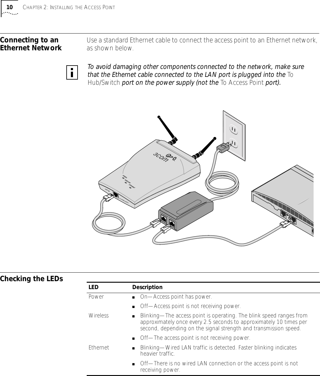
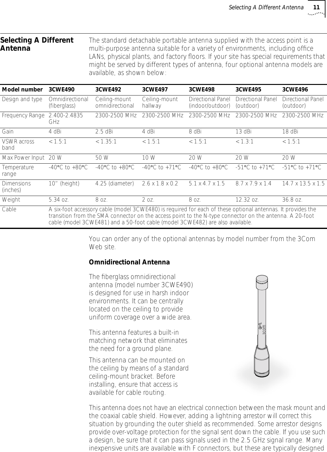
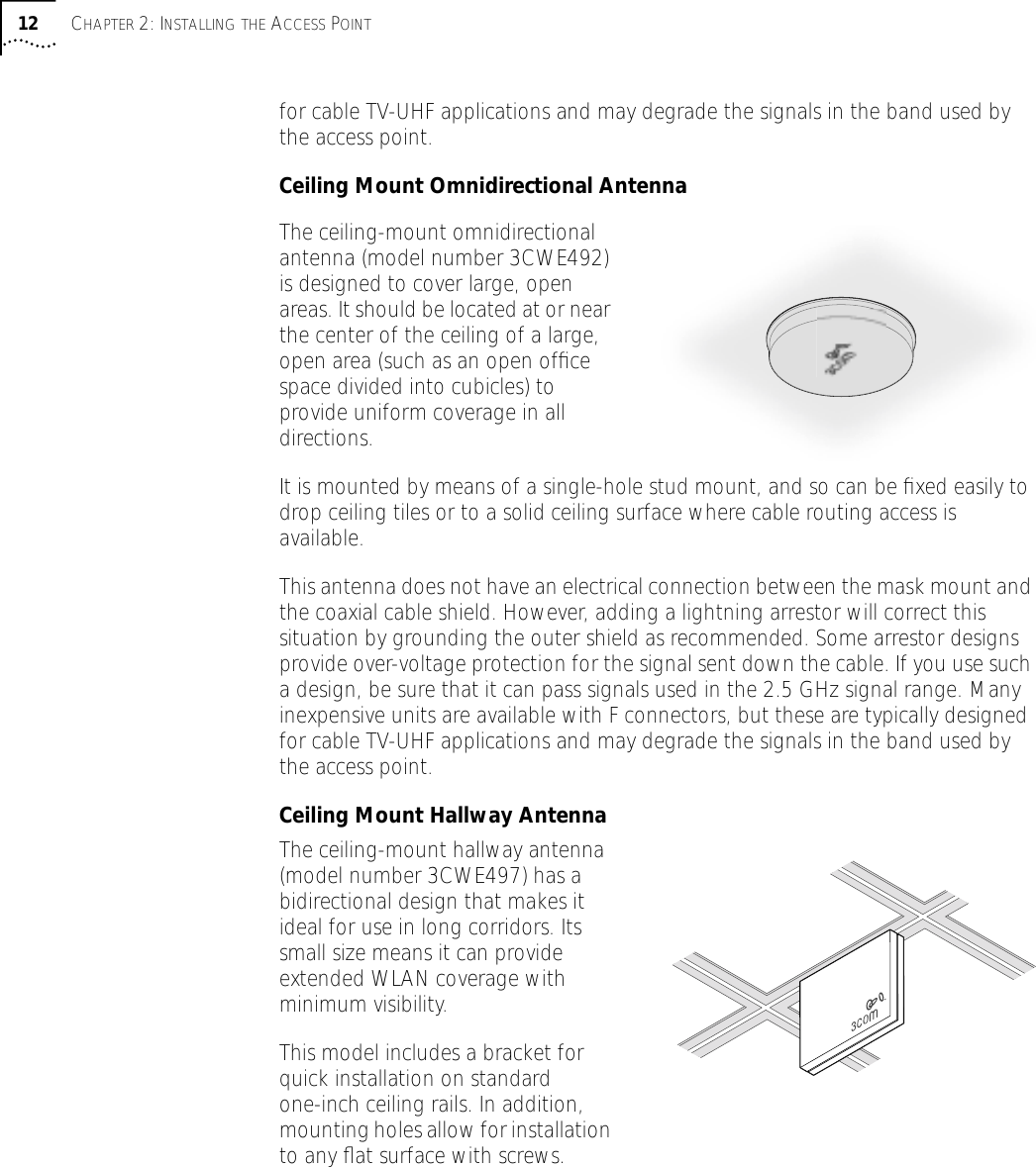
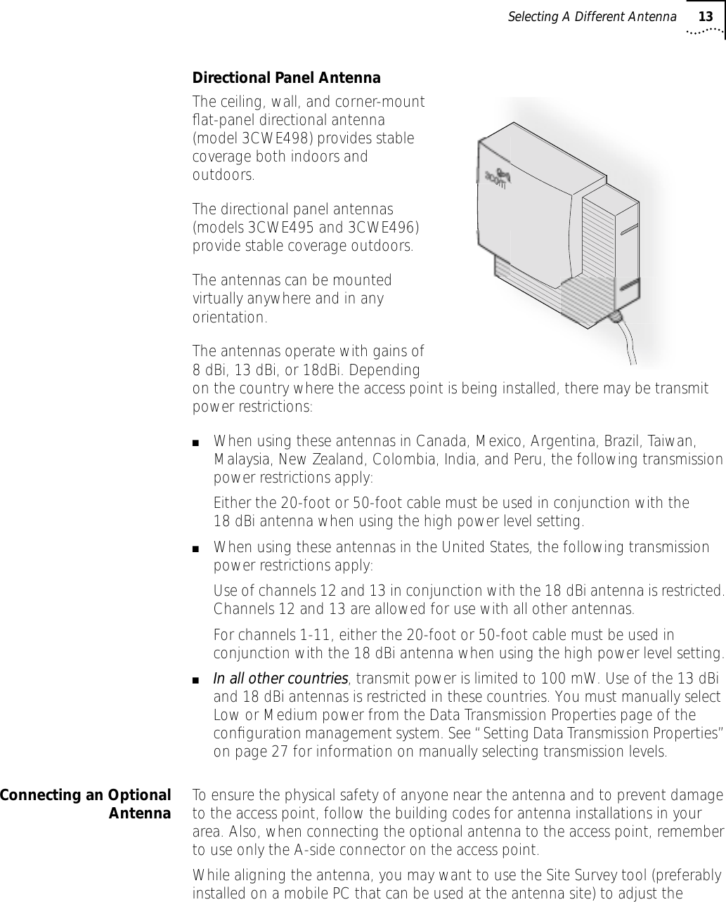
WL306 User Manual
modified manual
Navigation menu
Upload a User Manual
Namespaces
Wiki Guide
HTML
PDF
Info
Views
User Manual
Discussion / Help
Navigation