3Com WX1200 3CRWX120695A Wireless LAN Switch And Controller Hardware Installation Guide User Manual To The A21dc291 7bc7 4aa5 A020 484e108a989f
User Manual: 3Com WX1200 3CRWX120695A to the manual
Open the PDF directly: View PDF ![]() .
.
Page Count: 66
- About This Guide
- WX Switch Overview
- Installing and Connecting a WX Switch
- WX Technical Specifications
- WX Troubleshooting
- Obtaining Support for Your 3Com Products
- Index

http://www.3Com.com/
Part No. 10015911 Rev AB
Published November 2007
Wireless LAN Mobility System
Wireless LAN Switch and Controller
Hardware Installation Guide
WX4400 3CRWX440095A
WX2200 3CRWX220095A
WX1200 3CRWX120695A
WXR100 3CRWXR10095A
3Com Corporation
350 Campus Drive
Marlborough, MA USA
01752-3064
Copyright © 2007, 3Com Corporation. All rights reserved. No part of this documentation may be reproduced
in any form or by any means or used to make any derivative work (such as translation, transformation, or
adaptation) without written permission from 3Com Corporation.
3Com Corporation reserves the right to revise this documentation and to make changes in content from time
to time without obligation on the part of 3Com Corporation to provide notification of such revision or change.
3Com Corporation provides this documentation without warranty, term, or condition of any kind, either
implied or expressed, including, but not limited to, the implied warranties, terms or conditions of
merchantability, satisfactory quality, and fitness for a particular purpose. 3Com may make improvements or
changes in the product(s) and/or the program(s) described in this documentation at any time.
If there is any software on removable media described in this documentation, it is furnished under a license
agreement included with the product as a separate document, in the hard copy documentation, or on the
removable media in a directory file named LICENSE.TXT or !LICENSE.TXT. If you are unable to locate a copy,
please contact 3Com and a copy will be provided to you.
UNITED STATES GOVERNMENT LEGEND
If you are a United States government agency, then this documentation and the software described herein are
provided to you subject to the following:
All technical data and computer software are commercial in nature and developed solely at private expense.
Software is delivered as “Commercial Computer Software” as defined in DFARS 252.227-7014 (June 1995) or
as a “commercial item” as defined in FAR 2.101(a) and as such is provided with only such rights as are
provided in 3Com’s standard commercial license for the Software. Technical data is provided with limited rights
only as provided in DFAR 252.227-7015 (Nov 1995) or FAR 52.227-14 (June 1987), whichever is applicable.
You agree not to remove or deface any portion of any legend provided on any licensed program or
documentation contained in, or delivered to you in conjunction with, this User Guide.
Unless otherwise indicated, 3Com registered trademarks are registered in the United States and may or may
not be registered in other countries.
3Com and the 3Com logo are registered trademarks of 3Com Corporation.
Mobility Domain, Mobility Point, Mobility Profile, Mobility System, Mobility System Software, MP, MSS, and
SentrySweep are trademarks of Trapeze Networks, Inc.
Intel and Pentium are registered trademarks of Intel Corporation. Microsoft, MS-DOS, Windows, Windows XP,
and Windows NT are registered trademarks of Microsoft Corporation.
All other company and product names may be trademarks of the respective companies with which they are
associated.

CONTENTS
ABOUT THIS GUIDE
Conventions 6
Documentation 7
Documentation Comments 8
1WX SWITCH OVERVIEW
WX Model Numbers 9
Hardware Features 10
WX2200 Switch 10
WXR100 Switch 11
WX1200 Switch 12
WX4400 Switch 13
Management Features 14
Power Features 14
Network Interfaces 15
WX1200, WX4400, and WX2200 Status LEDs 16
WXR100 LEDs 17
Software Features 19
Management Features 19
Layer 2 Switching Features 19
IP Services 20
Authentication, Authorization, and Accounting 20
Roaming 20
RF Management 21
2INSTALLING AND CONNECTING A WX SWITCH
Unpacking a WX Switch 23
Installation Requirements and Recommendations 25
3Com Wireless Switch Manager Network Plan 25
Installation Location 25
Cable Requirements 26

Installation Hardware and Tools 29
Installing a WX Switch 30
Equipment Rack Installation 31
Tabletop Installation 33
Installing a Power Supply in a WX4400 Switch 34
Installing a New Power Supply 34
Replacing a Power Supply 35
Powering On a WX Switch 37
Powering On a WXR100 Switch 37
Connecting to a Serial Management Console 38
Troubleshooting a Serial Management Connection 39
Connecting to the Network 39
Connecting to a MAP or Other 10/100 Ethernet Device 39
Connecting to Gigabit Ethernet Devices 42
AWX TECHNICAL SPECIFICATIONS
BWX TROUBLESHOOTING
COBTAINING SUPPORT FOR YOUR 3COM PRODUCTS
Register Your Product to Gain Service Benefits 57
Solve Problems Online 57
Purchase Extended Warranty and Professional Services 58
Access Software Downloads 58
Contact Us 58
Telephone Technical Support and Repair 59
INDEX

ABOUT THIS GUIDE
This guide shows you how to install a 3Com Wireless LAN Switch (WX) in
a 3Com Mobility System wireless LAN (WLAN) and deploy basic IEEE
802.11 wireless service.
Read this guide if you are a network administrator or other person
installing WX switches and deploying 802.11 wireless service in a
network.
The 3Com Mobility System is an enterprise-class WLAN solution that
seamlessly integrates with an existing wired enterprise network. The
3Com system provides secure connectivity to both wireless and wired
users in large environments such as office buildings, hospitals, and
university campuses and in small environments such as branch offices.
The 3Com Mobility System fulfills the three fundamental requirements of
an enterprise WLAN: It eliminates the distinction between wired and
wireless networks, allows users to work safely from anywhere (secure
mobility), and provides a comprehensive suite of intuitive tools for
planning and managing the network before and after deployment,
greatly easing the operational burden on IT resources.
If release notes are shipped with your product and the information there
differs from the information in this guide, follow the instructions in the
release notes.
Most user guides and release notes are available in Adobe Acrobat
Reader Portable Document Format (PDF) or HTML on the 3Com
World Wide Web site:
http://www.3com.com/
6ABOUT THIS GUIDE
Conventions Table 1 and Table 2 list conventions that are used throughout this guide.
Table 1 Notice Icons
Icon Notice Type Description
Information note Information that describes important features or
instructions
Caution Information that alerts you to potential loss of data or
potential damage to an application, system, or device
Warning Information that alerts you to potential equipment
damage or personal injury.
Table 2 Text Conventions
Convention Description
Monospace text Sets off command syntax or sample commands and system
responses.
Bold text Highlights commands that you enter or items you select.
Italic text Designates command variables that you replace with
appropriate values, or highlights publication titles or words
requiring special emphasis.
[ ] (square brackets) Enclose optional parameters in command syntax.
{ } (curly brackets) Enclose mandatory parameters in command syntax.
| (vertical bar) Separates mutually exclusive options in command syntax.
Keyboard key names If you must press two or more keys simultaneously, the key
names are linked with a plus sign (+). Example:
Press Ctrl+Alt+Del
Words in italics Italics are used to:
Emphasize a point.
Denote a new term at the place where it is defined in the
text.
Highlight an example string, such as a username or SSID.

Documentation 7
Documentation The MSS documentation set includes the following documents.
Wireless Switch Manager (3WXM) Release Notes
These notes provide information about the 3WXM software release,
including new features and bug fixes.
Wireless LAN Switch and Controller Release Notes
These notes provide information about the MSS software release,
including new features and bug fixes.
Wireless LAN Switch and Controller Quick Start Guide
This guide provides instructions for performing basic setup of secure
(802.1X) and guest (WebAAA™) access, and for configuring a
Mobility Domain for roaming.
Wireless Switch Manager Reference Manual
This manual shows you how to plan, configure, deploy, and manage a
Mobility System wireless LAN (WLAN) using the 3Com Wireless Switch
Manager (3WXM).
Wireless Switch Manager User’s Guide
This guide shows you how to plan, configure, deploy, and manage a
Mobility System wireless LAN (WLAN) using the 3Com Wireless Switch
Manager (3WXM). It contains information about recommended
system requirements you should meet for optimum 3WXM
performance, installing 3WXM client and 3WXM Services software,
and an introduction to using the 3WXM interface.
Wireless LAN Switch and Controller Hardware Installation Guide
This guide provides instructions and specifications for installing a WX
wireless switch in a Mobility System WLAN.
Wireless LAN Switch and Controller Configuration Guide
This guide provides instructions for configuring and managing the
system through the Mobility System Software (MSS) CLI.
Wireless LAN Switch and Controller Command Reference
This reference provides syntax information for all MSS commands
supported on WX switches.

8ABOUT THIS GUIDE
Documentation
Comments
Your suggestions are very important to us. They will help make our
documentation more useful to you. Please e-mail comments about this
document to 3Com at:
pddtechpubs_comments@3com.com
Please include the following information when contacting us:
Document title
Document part number and revision (on the title page)
Page number (if appropriate)
Example:
Wireless LAN Switch and Controller Configuration Guide
Part number 730-9502-0071, Revision B
Page 25
Please note that we can only respond to comments and questions about
3Com product documentation at this e-mail address. Questions related to
Technical Support or sales should be directed in the first instance to your
network supplier.

1WX SWITCH OVERVIEW
A 3Com Wireless Switch (WX) provides mobility and authentication,
authorization, and accounting (AAA) services for wireless or wired users.
A WX switch also controls the operation of 3Com Managed Access Point
(MAP) access points, which control and manage IEEE 802.11 operation
over the air.
WARNING: Installation must be performed by qualified service personnel
only. Read and follow all warning notices and instructions marked on the
product or included in the documentation.
WARNING: There are no user-serviceable parts inside the WX switches.
WX Model Numbers Table 3 lists the WX switch model numbers.
Table 3 WX Switch Model Numbers
Model Port Configuration Power Supply Configuration
WX2200 Two gigabit Ethernet ports. Each
port has a miniature Gigabit
interface converter (mini-GBIC) slot
for insertion of a small form-factor
pluggable (SFP) 1000BASE-SX or
1000BASE-LX fiber-optic interface.
One 10/100 Ethernet port for out-of-
band management (without PoE).
Two 100-240V VAC autosensing
AC power supplies
WXR100 Two 10/100BASE-TX Ethernet ports
Port 1 provides an uplink to the
network.
Port 2 supports Power over Ethernet (PoE)
and provides direct connection to a MAP
One 100-240 VAC autosensing AC
power supply
WX1200 Eight 10/100 Ethernet ports, six of
which support PoE
One 100-120 VAC / 200-240 VAC
autosensing AC power supply
10 CHAPTER 1: WX SWITCH OVERVIEW
Hardware Features The following sections describe the WX hardware features.
WX2200 Switch A WX2200 switch is one RU high and also can be installed in a standard
48.26-cm (19-inch) equipment rack or on a tabletop. Figure 1 shows the
features of a WX2200 switch.
Figure 1 3Com WX2200 Switch
The rear of the switch contains a label with the serial ID, MAC address,
and other identifying information.
WX4400 Four dual-interface gigabit Ethernet
ports. Each port has a 1000BASE-TX
copper interface and a Gigabit
interface converter (GBIC) slot for
insertion of a 1000BASE-SX or
1000BASE-LX fiber-optic interface.
Two 100-120 VAC / 200-240 VAC
autosensing AC power supplies
Table 3 WX Switch Model Numbers (continued)
Model Port Configuration Power Supply Configuration
Provide an Earthing Connection
90 - 240V~ / 50 - 60 Hz
2.0 / 1.0A
Power
supplies
Power
supply LEDs
1Console 2
Mgmt (3)
Serial
console port
Gigabit link
LEDs
Mini-GBIC
slots
10/100
Management
Port
Mgmt
LED
Hardware Features 11
WXR100 Switch A WXR100 switch is compact and can be installed on a tabletop. Figure 2
shows the external hardware features of an WXR100 switch.
Figure 2 3Com WXR100 Switch
CAUTION: Do not stack WXR100 switches. Stacked WXR100 switches
can overheat and cause loss of equipment functionality or permanent
damage.
CAUTION: Ensure adequate airflow around WXR100 switches. The
WXR100 switch uses natural convection cooling and requires free entry
of air. Airflow blockage can cause the system to overheat and result in a
loss of equipment functionality or permanent damage.
The underside of the switch contains a label with the serial ID,
MAC address and other identifying information.
12 CHAPTER 1: WX SWITCH OVERVIEW
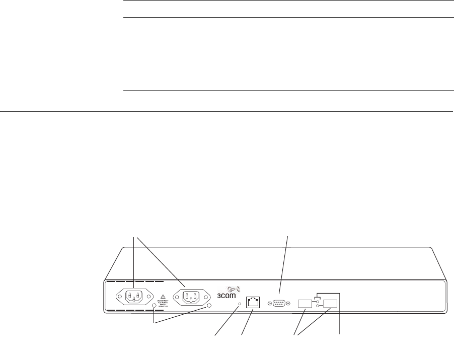
WX1200 Switch A WX1200 switch is one RU high and can be installed in a standard
48.26-cm (19-inch) equipment rack or on a tabletop. Figure 3 shows the
external hardware features of a WX1200 switch.
Figure 3 3Com WX1200 Switch—Control Features
The rear of the switch contains a label with the serial ID, MAC address,
and other identifying information.
Power
supply
Power
supply LED
10/100 Ethernet
uplink ports
10/100 and
MAP/PoE LEDs
10/100 and MAP
Ethernet ports
Serial
console port
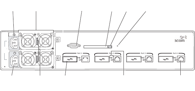
Hardware Features 13
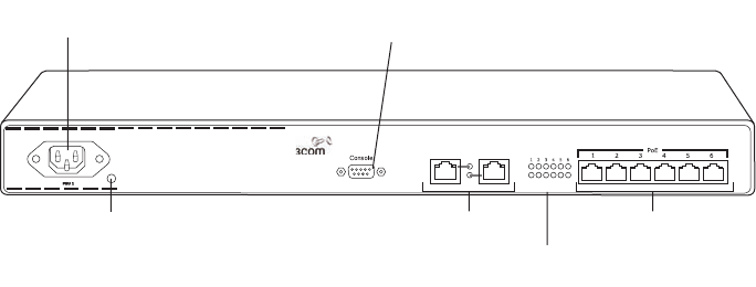
WX4400 Switch A WX4400 switch is two rack units (RUs) high and can be installed in a
standard 48.26-cm (19-inch) equipment rack or on a tabletop. Figure 4
identifies the external hardware features of a WX4400 switch.
Figure 4 3Com WX4400 Switch—Control Features
Like the WX1200, the rear of the WX4400 contains a label with the serial
ID, MAC address, and other identifying information.
100-240V
50/60 Hz
8A MAX
DISCONNECT
ALL POWER
BEFORE
SERVICING
Gigabit
link
LEDs
GBIC slotAC power
inlet
Power
supply
Power supply
serial number
Power
supply LED
Serial
console port
Flash
card slot
Eject
button
Mgmt
LED
1000BASE-TX port
Mgmt
Console

14 CHAPTER 1: WX SWITCH OVERVIEW
Management
Features
Serial console port—The serial console port provides a direct
management connection to a WX switch’s command-line interface
(CLI). The port has a DB-9 female connector and supports the
EIA-232D signaling standard.
10/100 out-of-band management port—The WX2200 switch features
an out-of-band management port, which allows you to connect the
switch to a network server and configure the switch to boot using a
software image downloaded from the server. The WXR100 also
supports booting with a software image downloaded from a server.
CAUTION: The Fn switch on the WXR100 performs two functions. If you
press the Fn switch for less than 5 seconds, it restarts the WXR100 and
reloads its configuration from the configuration file. However, if you
press the switch for 5 seconds or longer, the configuration file is deleted
and the switch restarts with its factory default settings. If you accidentally
press the Fn switch for too long and erase the configuration, you can use
the Web Quick Start to reconfigure the switch.
Status LEDs—The Ethernet ports and power supplies have LEDs that
indicate their status. The management CPU on a WX4400 or WX2200
switch also has an LED. (For details, see “WX1200, WX4400, and
WX2200 Status LEDs” on page 16.)
Flash card slot (WX4400 only)—The flash card slot is not used for
normal WX operation.
Power Features Power supplies—A WX4400 switch comes with one 100-240 VAC
autosensing AC power supply. You can add a second supply for load
sharing and redundancy. The power supplies are hot-swappable.
A WX1200 switch contains one 100-120 VAC / 200-240 VAC
autosensing AC power supply. The WX1200 power supply is a
fixed-configuration supply and cannot be inserted or removed.
A WX2200 switch contains two 100-240V VAC autosensing AC
power supplies.
A WXR100 switch uses an external power supply, which comes with
the switch.
Hardware Features 15
Network Interfaces 10/100 Ethernet ports—A WXR100 switch has two 10/100BASE-TX
Ethernet ports. A WX1200 switch has eight 10/100BASE-TX Ethernet
ports. Each port has a standard RJ-45 connector and uses Category 5
(Cat 5) cable based on the EIA/TIA-586 standard.
On the WXR100, port 2 can be configured for MAP access points and
can support Power over Ethernet (PoE). Port 1 is an uplink port only
and does not support PoE.
On the WX1200, ports 1 through 6 can be configured for MAP access
points and can support PoE. Ports 7 and 8 on the WX1200 switch are
uplink ports only and do not support PoE.
The 10/100 Ethernet ports on the WX1200, WX2200, and WXR100
switches provide automatic MDI/MDX, which automatically crosses
over the send and receive signals if required.
The WX4400 and WX2200 switches provide high-bandwidth
centralized control of many indirectly connected MAP access points.
The WX4400 switch does not have 10/100 Ethernet ports and does
not provide PoE. The WX2200 has one 10/100 Ethernet port (port 3);
this port does not provide PoE.
Gigabit interface converter (GBIC) slots (WX4400 only)—A WX4400
switch has four ports. Each port has a slot for a 1000BASE-SX or
1000BASE-LX fiber-optic GBIC, and a built-in 1000BASE-TX copper
interface with an RJ-45 connector. Only one interface, copper or fiber,
can be active on a port. The GBIC interface is active by default.
Miniature Gigabit interface converter (mini-GBIC) slots (WX2200
only)—A WX2200 switch has two slots allowing insertion of small
form-factor pluggable (SFP) 1000Base-SX, 1000Base-LX, 1000Base-T,
or 1000Base-LH fiber-optic mini-GBICs to provide gigabit Ethernet
interfaces to the network.
The mini-GBICs have standard SC Duplex connectors and use either
single-mode fiber (SMF) for LX or multimode fiber (MMF) for SX.
Mini-GBICs are available separately and are not included with the
switch.
The gigabit Ethernet ports operate at 1000 Mbps only. They do not
change speed to match 10-Mbps or 100-Mbps links.

16 CHAPTER 1: WX SWITCH OVERVIEW
WX1200, WX4400,
and WX2200 Status
LEDs
The WX1200, WX4400, and WX2200 switches have LEDs that indicate
port, power, and CPU status. Tab l e 4 lists the LEDs. (For the location of
each LED, see Figure 3 and Figure 4.)
Tabl e 4 WX1200, WX4400, and WX2200 Status LEDs
LED Appearance Meaning
Mgmt
(WX4400 and
WX2200 only)
Bright green, then
fade (repeated)
This LED appearance
is sometimes called
breathing.
WX switch is operating normally.
Blinking green WX switch is booting.
Quickly blinking
amber
WX switch was unable to boot completely.
Power supply
status
Solid green DC power output is on.
Solid amber Power fault has occurred.
Unlit AC power is off.
Gigabit fiber
link activity
(WX4400 and
WX2200 only)
Solid green 1000-Mbps fiber link is operational.
Blinking green Traffic is active on the 1000-Mbps fiber
link.
Gigabit copper
link activity
(WX4400 and
WX2200 only)
Solid green 1000-Mbps copper link is operational.
Blinking green Traffic is active on the 1000-Mbps copper
link.
Link
(WX1200 only)
Solid green 100-Mbps link is operational.
Solid amber 10-Mbps link is operational.
Blinking green Traffic is active on the 100-Mbps link.
Blinking amber Traffic is active on the 10-Mbps link.
Hardware Features 17
WXR100 LEDs Figure 5 shows the locations of the WXR100 LEDs. Table 5 describes the
LEDs.
Figure 5 WXR100 LEDs
MAP
(WX1200 only)
Solid green For a MAP access point’s active link, with
PoE enabled, all the following are true:
MAP access point has booted.
MAP access point has received a valid
configuration from the WX switch.
Management link with a MAP access
point is operational.
Alternating green
and amber
MAP access point is booting with an image
received from the WX switch.
If the LED remains in this state indefinitely,
the boot or configuration attempt has
failed.
Solid amber PoE is on but no MAP access point is
connected to the link.
Blinking amber MAP is not connected or is unresponsive,
or there is a PoE problem.
Unlit Port is not configured as a MAP access
port, or PoE is off.
Table 4 WX1200, WX4400, and WX2200 Status LEDs (continued)
LED Appearance Meaning
Power
supply LED
12
FN LED MAP LED
Link LED

18 CHAPTER 1: WX SWITCH OVERVIEW
Table 5 WXR100 Status LEDs
LED Appearance Meaning
Power status Solid green The switch is receiving power.
Unlit The switch is not receiving power.
Link
(ports 1 and 2)
Solid green 100-Mbps link is operational.
Solid amber 10-Mbps link is operational.
Blinking green Traffic is active on the 100-Mbps link.
Blinking amber Traffic is active on the 10-Mbps link.
Fn
(port 1 only)
Solid green The switch is booting and is loading its
configuration file. This LED state lasts
for three seconds.
Blinking green The switch is booting but the Fn
switch is being pressed. The switch
does not load its configuration file but
instead contacts WX to request a
configuration.
This LED state lasts for three seconds.
Unlit The switch has finished booting.
MAP (port 2 only) Solid green For a MAP access point’s active link,
with PoE enabled, all the following are
true:
MAP access point has booted.
MAP access point has received a valid
configuration from the WX switch.
Management link with an MAP access
point is operational.
Alternating green and
amber
MAP access point is booting with an
image received from the WX switch.
If the LED remains in this state
indefinitely, the boot or configuration
attempt has failed.
Solid amber PoE is on but no MAP access point is
connected to the link.
Blinking amber MAP is not connected or is
unresponsive, or there is a PoE
problem.
Unlit Port is not configured as a MAP access
port, or PoE is off.

Software Features 19
Software Features Mobility System Software (MSS) provides a combination of standard
wired LAN features and wireless LAN features that enable you to
integrate the switch into your wired network and provide network access
for wired or wireless users.
Management
Features
Serial and network command-line interface (CLI) access—You can
access the CLI through a direct serial connection or through the
network using Secure Shell (SSH) or Telnet.
3Com Wireless Switch Manager management application—3Com
Wireless Switch Manager is an extensive GUI application for planning,
configuring, deploying, and managing a 3Com network and its users.
3Com Wireless Switch Manager uses Secure Sockets Layer protocol
(SSL) to interact with MSS.
Software and configuration management—You can store multiple
software images and configuration files in the WX switch’s nonvolatile
storage.
Web View—Web View is a Web-based application for configuring and
managing a single WX switch through a Web browser. Web View
creates a secure connection by using Hypertext Transfer Protocol over
Secure Sockets Layer (HTTPS).
Layer 2 Switching
Features
Spanning Tree Protocol (STP)—MSS is 802.1D-compatible and
supports Per-VLAN Spanning Tree (PVST+). PVST+ allows a separate
spanning tree in each virtual LAN (VLAN). Optional fast convergence
features allow you to quickly resume traffic forwarding after a
topology change.
Load-sharing port groups—You can configure multiple physical ports
into a single logical link for traffic load sharing and physical link
redundancy.
Virtual LANs (VLANs)—MSS supports logical segmentation of a
switch’s ports into separate Layer 2 collision domains. A port can be a
member of one or more VLANs. Each VLAN can have its own IP
interface. MSS supports the 802.1Q tag format.
Internet Group Management Protocol (IGMP) snooping for multicast
containment—The WX switch can learn about the multicast sources
and receivers in the network and restrict forwarding for a multicast
group to the users for that group. IGMPv1 and IGMPv2 are supported.
20 CHAPTER 1: WX SWITCH OVERVIEW
IP Services IP interfaces—You can configure an IP interface for each VLAN.
IP ping and traceroute—You can test IP connectivity between the WX
switch and other devices.
Domain Name Service (DNS)—You can configure the switch to use
DNS servers for name resolution. You also can configure a default
domain name to append to hostnames.
Network Time Protocol (NTP)—A WX switch can sets its time and date
by polling an NTP server.
System log—A WX generates log messages to log system events. The log
messages are stored locally and also can be exported to syslog servers.
Simple Network Management Protocol (SNMP)—A WX switch can be
configured to generate SNMP traps for major system events.
Authentication,
Authorization, and
Accounting
802.1X—A WX switch can authenticate users based on 802.1X
protocols. Based on authentication, users are assigned VLAN
membership, access control, and roaming boundaries.
MAC authentication—If a device does not support 802.1X, you can
configure authentication based on the source MAC address to assign
VLAN membership, access control, and roaming boundaries.
Guest authentication—Guests can be authenticated by a shared set of
authorization attributes that assign VLAN membership, access control,
and roaming boundaries.
Local and remote authentication—You can authenticate users locally using
information configured on the WX switch, or use a Remote Authentication
Dial-In User Service (RADIUS) server. When you use a remote server, the WX
switch can enhance performance by performing some of the AAA tasks
locally or distributing the load across multiple servers.
Roaming MAP access point roaming—You can configure the WX switch to
allow users to roam from one MAP access point to another on the
same WX switch.
Mobility Domain™ roaming—You also can configure a group of WX
switches to allow users to roam from one switch to another.
Regardless of the wired subnet connections, each user maintains the
same IP address and session across the network.
Session management—You can display session information and
statistics for users.
Software Features 21
RF Management RF Auto-Tuning—MSS can automatically assign channels and power
settings to MAP access points based on RF information collected from
the network.
Radio frequency (RF) topology—With 3Com Wireless Switch Manager,
you can verify site coverage and capacity.
Rogue detection and countermeasures—MAPs can be used to gather
RF information for validating an RF deployment plan, and for
detecting and combatting rogue access points.
User-based RF—You can gather statistics on a per-user basis as users
roam across the network.
22 CHAPTER 1: WX SWITCH OVERVIEW

2INSTALLING AND CONNECTING A
WX SWITCH
Before installing a WX switch, you might need to generate a network
plan with 3Com Wireless Switch Manager. (See “3Com Wireless Switch
Manager Network Plan” on page 25.)
Unpacking a WX
Switch
The shipping carton for a WX switch contains the following items:
One WX switch, containing one power supply (except for the
WX2200, which has two power supplies)
For some countries, one country-specific power cord
One serial cable for connection to the management console (not
included with the WXR100)
Two rack-mount brackets (not applicable to the WXR100)
Four adhesive rubber feet
One documentation pack that includes this guide
One set of release notes
Figure 6 shows the contents of the shipping carton for a WX4400 switch.
The contents of a WX1200 and WX2200 shipping carton are similar. The
WXR100 carton contains the switch, a power supply and cord, rubber
feet, a documentation pack, and release notes.
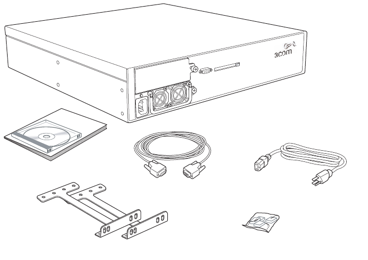
24 CHAPTER 2: INSTALLING AND CONNECTING A WX SWITCH
Figure 6 WX4400 Switch Shipping Carton Contents
Before you begin installation:
1Open the carton and carefully remove the contents, if you have not
already done so.
2Place the packing materials back in the carton and save the carton.
3Verify that you received each item in the previous list. If any item is
missing or damaged, contact 3Com.
Rack-mount brackets
WX switch with
installed power supply
Power cord
Serial cable
Rubber feet
Documentation pack

Installation Requirements and Recommendations 25
Installation
Requirements and
Recommendations
For best results, follow these requirements and recommendations before
installing a WX switch.
3Com Wireless Switch
Manager Network
Plan
If you are using 3Com Wireless Switch Manager to plan your 3Com
Mobility System installation, 3Com recommends that you create and
verify a network plan for the entire 3Com network installation before
installing WX switches or MAP access points. A network plan provides the
following information:
Number of WX switches required at your site, and where to install
them
Number of MAP access points required for adequate WLAN capacity
in each coverage area, and where to install them
Configuration settings for all the WX switches and MAP access points
in the WLAN, which can be automatically deployed to the devices by
3Com Wireless Switch Manager.
(For information about installing 3Com Wireless Switch Manager and
creating and verifying a network plan, see the Wireless Switch Manager
Reference Manual.)
Installation Location WX4400 switch fans and air inlets are located on the sides of the switch.
WX1200 and WX2200 switch fans are located in the rear of the switch and
air inlets are located on the sides of the switch. In the WX4400 switches,
separate power supply fans are located on the front. Make sure these areas
have adequate ventilation after installation. Do not block air vents.
WARNING: The WX switch has been designed and tested to be installed
in an operating ambient temperature of 0° C to +50° C (32° F to 122° F).
To reduce the risk of equipment damage, install equipment with
consideration to these ambient conditions.
WARNING: Do not stack WXR100 switches. Stacked WXR100 switches can
overheat and cause loss of equipment functionality or permanent damage.
WARNING: Ensure adequate airflow around WXR100 switches. The
WXR100 switch uses natural convection cooling and requires free entry
of air. Airflow blockage can cause the system to overheat and result in a
loss of equipment functionality or permanent damage.

26 CHAPTER 2: INSTALLING AND CONNECTING A WX SWITCH
Cable Requirements To avoid installation problems, use the proper cables.
WARNING: The gigabit Ethernet fiber-optic interfaces use Class 1 lasers.
To reduce the risk of eye injury, do not stare into the interface or
otherwise direct the laser beam into your eye.
Serial Console Cable
The serial console port has a female DB-9 connector and supports the
EIA-232D signaling standard. You need a standard
DB-9-male-to-DB-9-female PC modem cable. Table 6 lists the pin signals.
Network Cables
Table 7 lists the interface types supported by WX switches and the cable
type required for each type of interface.
Tabl e 6 Serial Console Pin Signals
WX Pin Usage PC Pin Usage
2Receive 3Transmit
3Transmit 2Receive
5Ground 5Ground
Tabl e 7 Ethernet Interfaces
Link Type Cable Type
Connector
Type
Maximum
Distance
100 BASE-T Cat 5 copper
Straight-through or crossover
signaling
RJ-45 100 m
(328 feet)
1000BASE-SX Multimode 50-µm fiber SC 550 m
(1804.5 feet)
Multimode 62.5-µm fiber SC 275 m
(902.2 feet)

Installation Requirements and Recommendations 27
The WX1200 supports 10/100 Ethernet connections. Table 8 lists the link
type and properties of the supported connections.
10/100 Ethernet Cable Wiring Connections on the 10/100 ports
require Category 5 (Cat 5) cable based on the EIA/TIA-586 standard. For
direct connection to a MAP access point, a router, or an end station such
as a PC, printer, or server, use a straight-through cable. For direct
connection to another switch, use a crossover cable. (The 10/100
Ethernet ports on the WX1200 switch provide automatic MDI/MDX,
which automatically crosses over the send and receive signals if required.)
Table 9 on page 28 lists the pin signals for 10/100 Ethernet
straight-through wiring. Pins 4, 5, 7, and 8 are used only when Power
over Ethernet (PoE) is enabled on the port. RD means Receive Data and
TD means Transmit Data.
1000BASE-LX Single mode 9/10-µm fiber SC 10,000 m
(32,808.4 feet)
Multimode 50-µm fiber SC 550 m
(1804.5 feet)
Multimode 62.5-µm fiber SC 550 m
(1804.5 feet)
1000BASE-TX Cat 5 copper
Can use straight-through or
crossover signaling, provided all four
wire pairs are connected
RJ-45 100 m
(328 feet)
Tabl e 8 Ethernet Interfaces
Link Type Cable Type
Connector
Type
Maximum
Distance
10/100BASE-T Cat 5 copper
Straight-through or
crossover signaling
RJ-45 100 m
(328 feet)
Table 7 Ethernet Interfaces (continued)
Link Type Cable Type
Connector
Type
Maximum
Distance

28 CHAPTER 2: INSTALLING AND CONNECTING A WX SWITCH
MAP Cable Requirement
Use a straight-through Ethernet cable to connect a MAP access point
directly to a WX switch or indirectly through another device.
1000BASETX Gigabit Ethernet Cable Wiring Use Cat 5 Enhanced
(Cat 5E) or better cable. 1000BASE-TX uses all 8 wires in the cable. The
wiring can be straight-through or crossover. The port automatically
configures its pin signals accordingly.
PoE is not supported on 1000BASE-TX links. All wires in the cable are
used for data.
Tabl e 9 10/100 Ethernet Straight-Through Pin Signals
WX Switch Other Device
Pin Function Pin Function
1RD+ 1TD+
2RD- 2TD-
3TD+ 3RD+
4PoE+ 4PoE+
5PoE+ 5PoE+
6TD- 6RD-
7PoE- 7PoE-
8PoE- 8PoE-

Installation Requirements and Recommendations 29
Installation Hardware
and Tools
Table 10 lists the mounting hardware and tools required for each type of
installation.
WARNING: To reduce the risk of equipment damage, make sure the WX
switch is installed so that the mechanical load on the device is evenly
distributed. For example, make sure the switch is level in the equipment
rack, is evenly fastened by screws on either side, and does not have a
heavy object resting on one side of the switch.
Tabl e 10 Required Mounting Hardware and Tools
Mounting Option Required Hardware and Tools
Included with
the Product
Equipment rack
Front-mount or
center-mount option for
the WX4400 switch
Front-mount option for
the WX1200 and
WX2200 switch
Mounting brackets Yes
Four rack-mount screws and
screwdriver
Note: Equipment racks vary, and
the screw and screwdriver type
depend on the equipment rack.
No
Power cords Yes (one)
Serial console cable Yes
Tabletop (applicable to all
switch models)
Four adhesive rubber feet Yes
Power cord(s) Yes
Serial console cable Yes
30 CHAPTER 2: INSTALLING AND CONNECTING A WX SWITCH
Installing a WX
Switch
You can mount a WX1200, WX4400, or WX2200 switch in a standard
48.26-cm (19-inch) equipment rack or on a tabletop. Each switch is
shipped with two brackets for rack mounting and four adhesive rubber
feet for tabletop mounting. The WX4400 mounting brackets support
either front or center mounting. The WX1200 and WX2200 mounting
brackets support front mounting only.
The WXR100 switch does not have rack mounting brackets but can be
installed on a tabletop.
To install a WX switch, use one of the following procedures.
WARNING: Earth grounding is required for a WX switch installed in a
rack. If you are relying on the rack to provide ground, the rack itself must
be grounded with a ground strap to the earth ground. Metal screws
attaching the switch to the rack provide ground attachment to the rack.
WARNING: In the U.S., overcurrent protection must be provided by the
installation. Branch circuit protection in accordance with National Fire
Protection Association (NFPA) 70, National Electrical Code (NEC) is
required. Consideration must be given to the electrical ratings on the WX
switch and branch circuit protection. Do not install equipment such that
the branch circuit current and voltage protection is exceeded. Pay
particular attention to the earthing connection for the supply
connections. When using an extension cord or power strip, pay attention
to the grounding type.
CAUTION: Do not stack WXR100 switches. Stacked WXR100 switches can
overheat and cause loss of equipment functionality or permanent damage.
CAUTION: Ensure adequate airflow around WXR100 switches. The
WXR100 switch uses natural convection cooling and requires free entry
of air. Airflow blockage can cause the system to overheat and result in a
loss of equipment functionality or permanent damage.
Installing a WX Switch 31
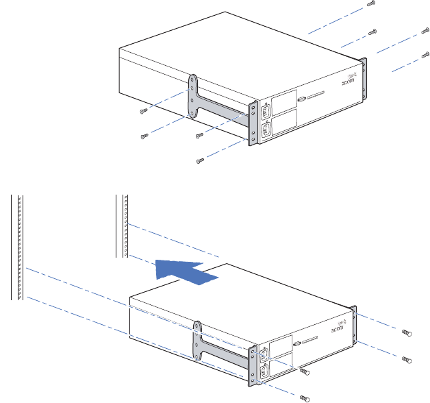
Equipment Rack
Installation
You can install a WX4400 switch into a front-mount or center-mount
equipment rack. You can install a WX2200 or WX1200 switch into a
front-mount equipment rack.
Figure 7 shows how to install a WX4400 switch into a front-mount
equipment rack. (Installation of a WX1200 or WX2200 switch is
similar.)
Figure 8 shows how to install a WX4400 switch into a center-mount
equipment rack.
Refer to these figures as you perform the procedure.
Figure 7 WX4400 Installation—Front-Mount Equipment Rack
First, attach brackets to chassis.
Then, install chassis into rack.
32 CHAPTER 2: INSTALLING AND CONNECTING A WX SWITCH
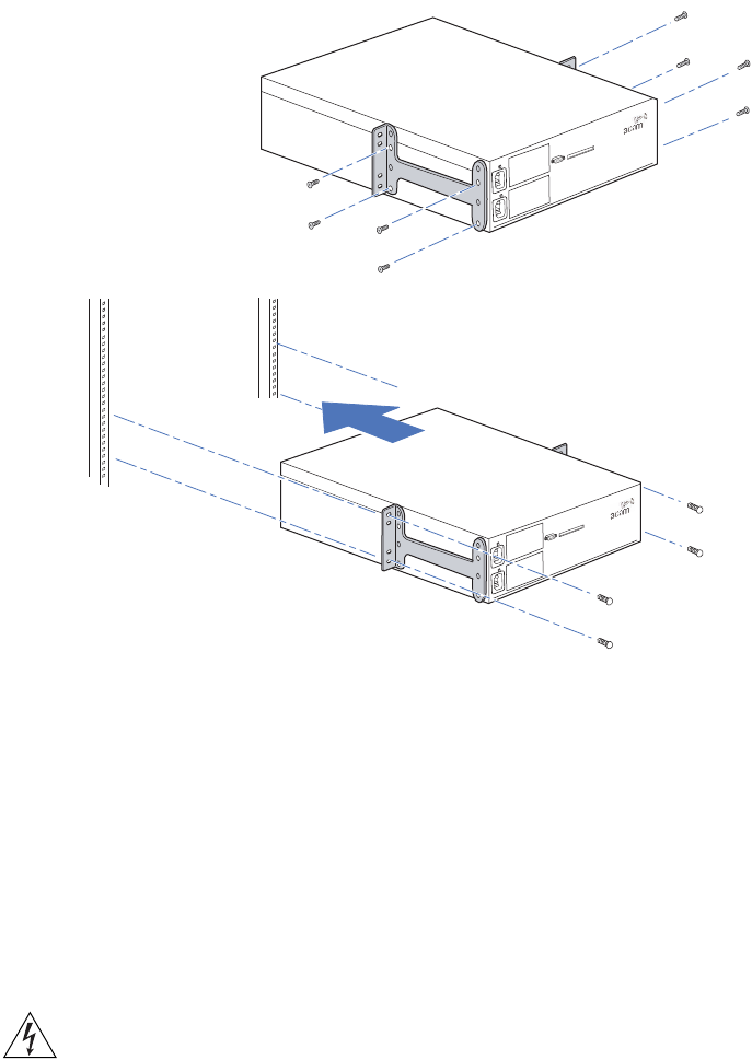
Figure 8 WX4400 Installation—Center-Mount Equipment Rack
1Remove the four bracket screws from each side of the WX switch.
2Align a bracket over the screw holes:
For a front-mount equipment rack, align the bracket so that the
bracket flange is flush with the WX switch’s front panel and extends
away from the switch.
For a center-mount equipment rack, align the bracket so that the
bracket flange is located near the center screw holes.
3Reinsert the screws to secure the brackets to the WX switch.
4Repeat for the other bracket.
WARNING: 3Com recommends that you ask someone to assist you with
the remaining steps. If you accidentally drop the WX switch, you can be
injured and the switch can be damaged.
First, attach brackets to chassis.
Then, install chassis into rack.

Installing a WX Switch 33
5Lift the WX switch into position in the equipment rack.
WARNING: To prevent the WX switch from slipping, do not release the
switch until all the rack-mount screws are tight.
6Insert the bottom rack-mount screws into the bracket flanges to secure
the WX switch to the equipment rack, then insert the top screws.
7Do one of the following:
If you are installing a second power supply into the switch, go to
“Installing a Power Supply in a WX4400 Switch” on page 34.
If you are ready to turn on power, go to “Powering On a WX Switch”
on page 37.
Tabletop Installation
1On a clean work surface with no debris, carefully turn the WX switch
upside down.
2Wipe the four placement locations for the rubber feet to clear away any
oil or dust. The location areas are marked by X’s.
3Attach the four rubber adhesive feet over the X’s.
4Turn the WX switch right-side up, and place the switch in position on the
table.
5Do one of the following:
If you are installing a second power supply into the switch, go to
“Installing a Power Supply in a WX4400 Switch” on page 34.
If you are ready to turn on power, go to “Powering On a WX Switch”
on page 37.

34 CHAPTER 2: INSTALLING AND CONNECTING A WX SWITCH
Installing a Power
Supply in a WX4400
Switch
A WX4400 switch is shipped with a single 100-240 VAC autosensing AC
power supply. One power supply provides enough power for a fully
configured system. You can add a second power supply for load sharing
and redundancy. A WX4400 switch containing one power supply can
have the supply installed in either slot. If the switch contains two power
supplies and one supply fails, the other supply automatically takes over to
provide uninterrupted operation.
The power supplies are hot-swappable. You can remove or insert a power
supply while the other power supply is running.
Use the following procedures to install a second power supply or replace
a failed power supply.
To attach the power supply to an WXR100, see “Powering On a WX
Switch” on page 37.
Installing a New
Power Supply
1If you are replacing a failed power supply and have not already removed it
from the WX switch, go to “Replacing a Power Supply” on page 35.
2If you are installing a new power supply in an unused slot, loosen the
thumbscrew with a #2 Phillips-head screwdriver and remove the cover plate.
Store the cover plate in a safe place in case you need to use it at another
time.
3Remove the new power supply from its packaging and lift the supply by
grasping the front handle with one hand and supporting the supply from
the bottom with the other hand.
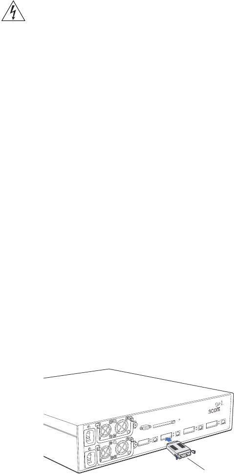
4Insert the power supply into the WX switch’s slot as shown in Figure 9,
pushing gently but firmly until the supply is fully seated and flush with the
switch’s front panel.
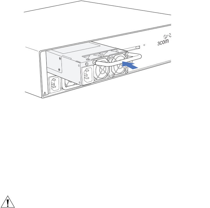
Installing a Power Supply in a WX4400 Switch 35
Figure 9 Inserting a Power Supply in a WX4400 Switch
5Tighten the thumbscrew using a #2 Phillips-head screwdriver.
6Go to “Powering On a WX Switch” on page 37.
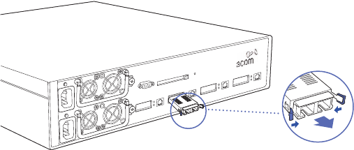
Replacing a Power
Supply
1Remove the power cord from the power supply.
2Loosen the thumbscrew using a #2 Phillips-head screwdriver as shown in
Figure 10.
3Use the handle to pull the power supply partway out of the slot as shown
in Figure 10.
CAUTION: Support the bottom of the power supply while removing it
from the WX switch. If the rear of the power supply is not supported, the
supply will fall when you remove it, possibly damaging the rear
components of the supply.


Powering On a WX Switch 37
Powering On a WX
Switch
WARNING: The WX switch relies on the building’s installation for
overcurrent protection. Ensure that a fuse or circuit breaker no larger
than 120 VAC, 15 A U.S. (240 VAC, 10 A international) is used on the
phase conductors.
CAUTION: If a WX1200 or WXR100 switch is connected to Power
Sourcing Equipment (PSE), it is possible for the switch to remain powered
on even when the power cord is unplugged. PSE can be a dedicated PoE
injector or even another networking switch such as the WX that is
capable of supplying PoE. To completely power off a WX1200 or
WXR100, unplug the power cord, then unplug all Ethernet cables that
are connected to other PoE devices.
To power on a WX1200, WX4400, or WX2200 switch:
1Make sure any power supply is fully seated in the WX switch.
2For each power supply that you are using on the WX switch, attach a
power cord to an AC power source.
3Plug the power cord into the WX power supply.
The WX switch begins booting as soon as you plug in the power cord(s).
4Observe the power supply LED for each connected power supply to verify
that the LED is steadily glowing green. This indicates normal power
supply operation.
5On the WX4400 switch only, wait a few seconds, then observe the
Mgmt LED to verify that it is breathing (repeatedly flashing bright green,
then fading) to indicate that the WX switch has successfully booted and is
operating normally.
Powering On a
WXR100 Switch
To power on a WXR100 switch:
1Plug the power supply into an AC power source.
2Plug the power supply into the Power port.
The LED turns green when the WXR100 is receiving power.
38 CHAPTER 2: INSTALLING AND CONNECTING A WX SWITCH
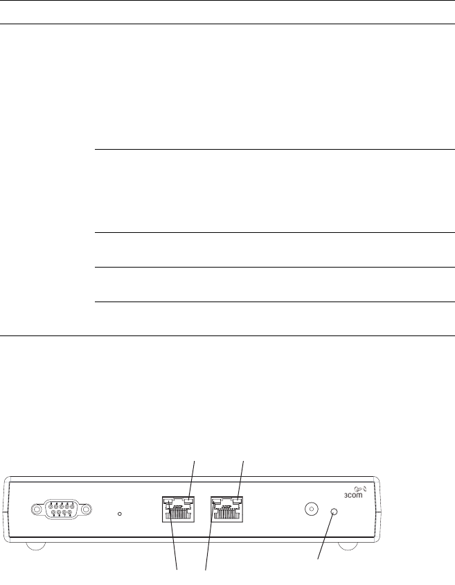
Connecting to a
Serial Management
Console
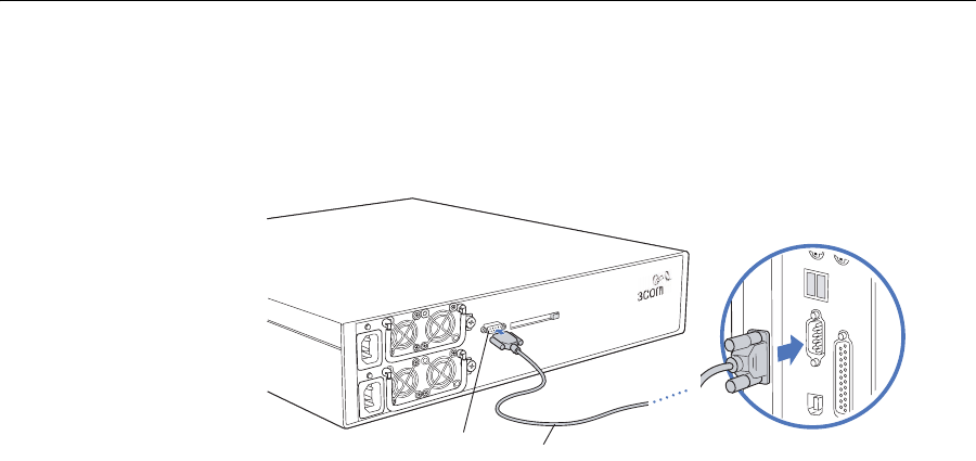
Initial configuration of the WX switch requires a connection to the switch’s
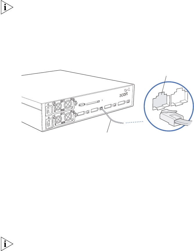
CLI through the serial console port. Figure 11 shows how to install a serial
cable on the WX switch. Refer to this figure as you perform the procedure.
(For cable requirements, see “Serial Console Cable” on page 26.)
Figure 11 Serial Cable Installation
To connect a PC to the serial console port:
1Insert the serial cable into the PC port as shown in Figure 11.
2Insert the other end of the cable into the serial console port on the WX
switch as shown in Figure 11.
3Start a standard VT100 terminal emulation application on the PC, and
configure the following modem settings:
9600 bps
8 bits
1 stop
No parity
Hardware flow control off or disabled
4Open a connection on a serial port.
If the WX switch is already powered on, press Enter three times to
display a command prompt. For example:
WX1200>
See “Using the quickstart Command (any model)” of the “Mobility
System Software Quick Start Guide” for instructions.
If a command prompt does not appear, go to “Troubleshooting a
Serial Management Connection”.
Serial port Serial cable Serial port on computer

Troubleshooting a Serial Management Connection 39
Troubleshooting a
Serial Management
Connection
If a command prompt does not appear when attempting to initiate a
serial management connection, do the following:
1Verify that the WX switch is powered on.
2Verify that the serial cable is fully inserted in the PC and WX switch ports.
3Verify that the correct modem settings are configured in the terminal
emulation application:
9600 bps
8 bits
1 stop
No parity
Hardware flow control disabled
4Verify that you opened the connection on the PC port connected to the
WX switch.
For example, if you inserted the cable in PC port COM1, make sure you
open the connection on COM1 instead of COM2 or another port.
If none of the previous steps results in a management connection, use
another serial cable.
Connecting to the
Network
Use the following procedures to connect a WX switch to MAP access
points or other 10/100 Ethernet devices and to gigabit Ethernet devices.
Connecting to a MAP
or Other
10/100 Ethernet
Device
The 10/100 Ethernet ports are configured as wired network ports by
default. You must change the port type for locally connected MAP access
points, and for wired end stations that use AAA through the WX switch
to access the network.
40 CHAPTER 2: INSTALLING AND CONNECTING A WX SWITCH
For installations in Japan: Provide an earthing connection before you
connect the mains plug to the mains. When disconnecting the earthing
connection, make sure to disconnect only after you pull out the mains
plug for the mains.
Figure 12 shows how to install a Cat 5 cable for a 10/100 Ethernet port.
Refer to this figure as you perform the procedure.
Figure 12 10/100 Cat 5 Cable Installation
To connect to a MAP or other 10/100 Ethernet device:
1Insert a Cat 5 cable with a standard RJ-45 connector:
For direct connection to a MAP access point, use a straight-through
cable.
For connection to a router or to an end station such as a PC, printer, or
server, use a straight-through cable.
For connection to another switch, use a crossover cable. (For cable
requirements, see “Network Cables” on page 26.)
The 10/100 Ethernet ports on WXR100, WX1200, and WX2200 switches
provide automatic MDI/MDX.
2If the cable is directly attached to a MAP access point:
For a first-time installation, set the port type to activate the link. (For
information, see “Setting the Port Type” in the Wireless LAN Switch
and Controller Configuration Guide.
If the port type is already set for a MAP access point, observe the
appearance of the MAP LED for the port:
Ethernet cable
(Cat 5 cable)
MAP, switch, server
or other device
Ethernet port

Connecting to the Network 41
3If the cable is attached to a wired end station that uses AAA through the
WX switch to access the network:
For a first-time installation, set the port type to activate the link. (For
information, see “Setting a Port for a Wired Authentication User” in
the Wireless LAN Switch and Controller Configuration Guide.)
If the port type is already set for a wired authentication port, go on to
step 4.
4If the cable is directly attached to a device other than a MAP access point:
aObserve the appearance of the Link LED for the port:
bIf the Link LED is unlit, check the cable and verify that the device at the
other end of the link is operating.
MAP LED Appearance Meaning
Solid green For a MAP access point’s active link, with PoE enabled,
all the following are true:
MAP access point has booted.
MAP access point has received a valid
configuration from the WX switch.
Management link with a MAP access point is
operational.
For a MAP access point’s secondary link, the link is
present.
Alternating green and
amber
MAP access point is booting with an image received
from the WX switch.
Solid amber PoE is on, but no MAP access point is connected to
the link.
Blinking amber MAP access point is unresponsive or there is a PoE
problem.
Unlit PoE is off.
Link LED Appearance Meaning
Solid green 100-Mbps link is operational.
Solid amber 10-Mbps link is operational.
Blinking green Traffic is active on the 100-Mbps link.
Blinking amber Traffic is active on the 10-Mbps link.
Unlit Link is not operational.
42 CHAPTER 2: INSTALLING AND CONNECTING A WX SWITCH
Connecting to Gigabit
Ethernet Devices
The following procedures explain how to connect a WX4400 switch’s
copper or fiber Gigabit port to the network.
WARNING: The gigabit Ethernet fiber-optic interfaces use Class 1 lasers.
To reduce the risk of eye injury, do not stare into the interface or
otherwise direct the laser beam into your eye.
Connecting to a Copper Gigabit Device (WX4400 only)
Insert a Cat 5 cable with a standard RJ-45 connector. The cable can use
straight-through or crossover signalling.
1Insert the Cat 5 cable into the port’s RJ-45 (copper) interface.
2Access the command-line interface (CLI) on the switch, use the enable
command to enter configuration mode, and use the following command
to set the active interface on the port to RJ-45 (copper):
set port media-type port-list rj45
3Observe the lower LED to the left of the port:
If the LED is solid green, the 1000-Mbps link is operational.
If the LED is blinking green, traffic is active on the 1000-Mbps link.
If the LED is unlit, the link is not operational. Check the cable and
verify that the device at the other end of the link is operational.
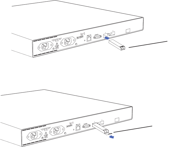
Connecting to a Fiber Gigabit Device
You must install a gigabit interface converter (GBIC) to connect a
WX4400 switch to 1000BASE-SX or 1000BASE-LX cable. Figure 13 shows
how to install a GBIC Figure 14 shows how to remove one. Refer to these
figures as you perform the procedures. (For cable requirements, see
“Network Cables” on page 26.)
Figure 13 GBIC Installation in a WX4400 Switch
GBIC
Connecting to the Network 43
Figure 14 GBIC Removal from a WX4400 Switch
To install a GBIC:
1Insert the GBIC into a GBIC slot on the front panel until it clicks into place.
2Remove the protective covering(s) from the port connector(s) and set
them aside in a safe place for later use.
3Insert the network cable.
For 1000BASE-SX or 1000BASE-LX fiber, make sure you insert the two
cable ends in the proper sides (transmit or receive). Otherwise, the link
does not work.
4Observe the upper LED to the right of the GBIC port:
If the LED is green, the 1000-Mbps link is operational.
If the LED is blinking amber, traffic is active on the 1000-Mbps link.
If the LED is unlit, the link is not operational. Check the cable and
verify that the device at the other end of the link is operational.
To re m ove a G B I C:
1Remove the network cable(s).
2Insert the protective covering(s) into the port connector(s).
3Squeeze the clips on the sides of the GBIC and pull the GBIC out of the
slot.
Squeeze the
lock clips to
release GBIC.
44 CHAPTER 2: INSTALLING AND CONNECTING A WX SWITCH
Connecting to a Fiber Gigabit Device (WX2200)
You must install a miniature gigabit interface converter (mini-GBIC) to
connect a WX2200 switch to 1000BASE-SX, 1000BASE-LX, or
1000BASE-TX cable.
Figure 15 shows how to install a mini-GBIC. Figure 16 shows how to
remove one. Refer to these figures as you perform the procedures. (For
cable requirements, see “Network Cables” on page 26.)
Figure 15 Mini-GBIC Installation in WX2200 Switch
Figure 16 Mini-GBIC removal from WX2200 Switch
Mini-GBIC
Grasp bail latch
and pull to remove
mini-GBIC.

Connecting to the Network 45
To install a mini-GBIC:
1Insert the mini-GBIC into a mini-GBIC slot on the front panel until it clicks
into place.
2Remove the protective covering(s) from the port connector(s).
3Insert the network cable.
For 1000BASE-SX or 1000BASE-LX fiber, make sure you insert the two
cable ends in the proper sides (transmit or receive). Otherwise, the link
does not work.
4Observe the LED next to the mini-GBIC port:
If the LED is green, the 1000-Mbps link is operational.
If the LED is blinking amber, traffic is active on the 1000-Mbps link.
If the LED is unlit, the link is not operational. Check the cable and
verify that the device at the other end of the link is operational.
To remove a mini-GBIC:
1Remove the network cable(s).
2Insert the protective covering(s) into the port connector(s).
3Pull the bail latch on the mini-GBIC forward, away from the WX switch,
to unlock it from the front panel.
4Grasping the bail latch, pull the mini-GBIC out of the slot.
46 CHAPTER 2: INSTALLING AND CONNECTING A WX SWITCH

AWX TECHNICAL SPECIFICATIONS
See the appropriate table for the technical specifications for the following
wireless switch models:
Table 11 — Wireless switch model WX4400
Table 12 — Wireless switch model WX1200
Table 13 — Wireless switch model WXR100
Table 14 — Wireless switch model WX2200
Tabl e 11 WX4400 Mechanical and Compliance Specifications
Specification Description
Size Width: 44.2 cm (17.4 inches)
Depth: 46.23 cm (18.2 inches)
Height: 8.81 cm (3.47 inches)
Weight With one power supply: 9.75 kg (21.50 pounds)
With two power supplies: 11.35 kg (25.00 pounds)
Operating Temperature 0° C to +50° C (32° F to +122° F)
Storage Temperature -20° C to +70° C (-4° F to +158° F)
Humidity 10% to 95% noncondensing
Power supply 100-240 VAC
50 Hz to 60 Hz
Up to 350 W
8 Arms at 120 Vrms and 3.5 Arms at 230 Vrms, with
50-A peak inrush current
Hot-swappable
Load sharing with two supplies installed

48 CHAPTER A: WX TECHNICAL SPECIFICATIONS
Status indicators Management CPU status LED
Power supply status LEDs
Port activity and link speed LEDs
(For descriptions of the LEDs, see “WX1200,
WX4400, and WX2200 Status LEDs” on page 16.)
Wired network ports Four dual-interface gigabit Ethernet ports. Each port
has a 1000BASE-TX copper interface and a GBIC slot
for insertion of a 1000BASE-SX or 1000BASE-LX
fiber-optic interface.
Safety and electromagnetic
compliance
FCC PART 15, UL 60950
ICES PART 15, CSA 22.2 NO. 60950
EN 55022, EN 55024
CISPR 22
TUV/GS (EN 60 950)
VCCI
Tabl e 12 WX1200 Mechanical and Compliance Specifications
Specification Description
Size Width: 44.2 cm (17.4 inches)
Depth: 25.6 cm (10.08 inches)
Height: 4.4 cm (1.72 inches)
Weight Without a power supply: 3.40 kg (7.50 pounds)
With power supply: 3.8 kg (8.50 pounds)
Operating Temperature 0° C to +50° C (32° F to +122° F)
Storage Temperature -20° C to +70° C (-4° F to +158° F)
Humidity 10% to 95% noncondensing
Power supply 100-120 VAC / 200-240 VAC
47 Hz to 63 Hz
2.5 Arms at 115 Vrms and 1.25 Arms at 230 Vrms, with
70-A peak inrush current
Power over Ethernet (PoE) 48 VDC
91.8 W total budget for all ports (15.3 W * 6 ports)
15.3 W per port maximum
Table 11 WX4400 Mechanical and Compliance Specifications (continued)
Specification Description

49
Status indicators Power supply status LEDs
Port activity and link speed LEDs
(For descriptions of the LEDs, see “WX1200,
WX4400, and WX2200 Status LEDs” on page 16.)
Wired network ports Six RJ-45 ports for 10/100BASE-T Ethernet and
optional Power over Ethernet (PoE)
Two RJ-45 ports for 10/100BASE-T Ethernet uplinks
(without PoE)
Safety and electromagnetic
compliance
FCC PART 15, UL 60950
ICES PART 15, CSA 22.2 NO. 60950
EN 55022, EN 55024
CISPR 22
TUV/GS (EN 60 950)
VCCI
Tabl e 13 WXR100 Mechanical and Compliance Specifications
Specification Description
Size Width: 19.0 cm (7.5 inches)
Depth: 14.6 cm (5.75 inches)
Height: 3.18 cm (1.25 inches)
Weight 0.7 kg (1.5 pounds)
Operating Temperature 0° C to +50° C (32° F to +122° F)
Storage Temperature -20° C to +70° C (-4° F to +158° F)
Humidity 10% to 95% noncondensing
Power supply Input: 100-240 VAC, 47-63 Hz, auto-sensing
Output: 48 VDC, 0.83A
Amperage draw maximums:
At 115V (RMS): 0.8A
At 230V (RMS): 0.4A
Power over Ethernet (PoE) Voltage output: 48 VDC
Wattage on port: 15.4 W
Table 12 WX1200 Mechanical and Compliance Specifications (continued)
Specification Description

50 CHAPTER A: WX TECHNICAL SPECIFICATIONS
Status indicators Power supply status LED
Port activity and link speed LEDs
Fn LED
(For descriptions of the LEDs, see “WXR100 LEDs” on
page 17.)
Wired network ports One RJ-45 port for 10/100BASE-T Ethernet and
optional Power over Ethernet (PoE)
One RJ-45 10/100BASE-T Ethernet uplink (without
PoE)
Safety and electromagnetic
compliance
FCC PART 15 Class B, UL 60950
ICES Class B, CSA 22.2 NO. 60950
EN 55022 Class B, EN 55024, EN 60950
EN 60101-1-2 EU Medical Directive
CISPR 22 Class B
VCCI Class B
Tabl e 14 WX2200 Mechanical and Compliance Specifications
Specification Description
Size Width: 44.2 cm (17.4 inches)
Depth: 30.7 cm (12.1 inches)
Height: 4.4 cm (1.72 inches)
Weight 4.54 kg (10 pounds)
Operating Temperature 0° C to +50° C (32° F to +122° F)
Storage Temperature -20° C to +70° C (-4° F to +158° F)
Humidity 10% to 95% noncondensing
Power supply Input: 100-240 VAC, 50-60 Hz
1 Arms at 120 VAC and 0.51 Arms at 230 VAC
17 A max. at 120 VAC and 32 A max. at 230 VAC
Status indicators Management CPU status LED
Power supply status LEDs
Port activity and link speed LEDs
(For descriptions of the LEDs, see “WX1200,
WX4400, and WX2200 Status LEDs” on page 16.)
Table 13 WXR100 Mechanical and Compliance Specifications (continued)
Specification Description

51
Wired network ports Two miniature gigabit interface converter (mini-GBIC)
slots for 1000BASE-SX, 1000BASE-LX, or
1000BASE-TX gigabit Ethernet ports
One RJ-45 port for 10/100BASE-T Ethernet (without
PoE) used for out-of-band management
Safety and electromagnetic
compliance
Regulatory Safety:
UL 60950
TUV/GS (EN 60 950)
CSA 22.2 NO. 60950
EMI/EMC:
FCC PART 15 Class A
ICES PART 15 Class A
VCCI Class A
EN 55022 Class A
EN 55024
CISPR 22 Class A
Taiwan: CNS 13438 Class A
China: CCC GB 9254-88 Class A
Australia/New Zealand: AS/NZ 3548 Class A
Environmental:
EN Directive 2002/95/EC: RoHS (Restriction of the
use of certain hazardous substances in electrical
and electronic equipment)
EN Directive 2003/108/EC: WEEE (Waste of
electrical and electronic equipment)
Table 14 WX2200 Mechanical and Compliance Specifications (continued)
Specification Description
52 CHAPTER A: WX TECHNICAL SPECIFICATIONS

BWX TROUBLESHOOTING
Table 15 contains remedies for some common problems that can occur
during basic installation and setup of a WX switch.
Tabl e 15 WX Setup Problems and Remedies
Symptom Diagnosis Remedy
3Com Wireless
Switch Manager or
a web browser (if
you are using Web
View) warns that
the WX switch’s
certificate date is
invalid.
The switch’s time and date
are currently incorrect, or
were incorrect when you
generated the self-signed
certificate or certificate
request.
1Use set timezone to set the
time zone in which you are
operating the switch. (See
“Setting the Time Zone” in
the Wireless LAN Switch and
Controller Configuration
Guide.)
2Use set timedate to
configure the current time
and date in that time zone.
(See “Statically Configuring
the System Time and Date”
in the Wireless LAN Switch
and Controller Configuration
Guide.)
3Reconfigure the
administrative certificate(s).
(See “Creating Keys and
Certificates” in the Wireless
LAN Switch and Controller
Configuration Guide.)
4If you have already
configured a certificate on
the switch for authentication
by network users, you must
recreate this certificate, too.

54 CHAPTER B: WX TROUBLESHOOTING
WX switch does not
accept
configuration
information for an
MAP access point or
a radio.
The country code might
not be set or might be set
for another country.
1Type the display system
command to display the
country code configured on
the switch.
2If the value in the System
Countrycode field is NONE or
is for a country other than
the one in which you are
operating the switch, use the
set system countrycode
command to configure the
correct country code. (See
“Specifying the Country of
Operation” in the Wireless
LAN Switch and Controller
Configuration Guide.)
Client cannot access
the network.
This symptom has more
than one possible cause:
The client might be
failing authentication or
might not be
authorized for a VLAN.
1Type the display aaa
command to check the
authentication rules on the
WX switch, to ensure that
the client can be
authenticated.
2Check the authorization rules
in the switch’s local database
(display aaa) or on the
RADIUS servers to ensure the
client is authorized to join a
VLAN that is configured on at
least one of the WX switches
in the Mobility Domain.
If the client and switch
configurations are
correct, a VLAN might
be disconnected. A
client connected to a
VLAN that is
disconnected is unable
to access the network.
1Type the display vlan
config command to check
the status of each VLAN.
2If a VLAN is disconnected
(VLAN state is Down), check
the network cables for the
VLAN’s ports. At least one of
the ports in a VLAN must
have a physical link to the
network for the VLAN to be
connected.
Table 15 WX Setup Problems and Remedies (continued)
Symptom Diagnosis Remedy

55
Configuration
information
disappears after a
software reload.
The configuration changes
were not saved.
1Retype the commands for the
missing configuration
information.
2Type the save config
command to save the
changes.
Mgmt LED is quickly
blinking amber.
CLI stops at boot
prompt (boot>).
The WX switch was unable
to load the system image
file.
Type the boot command at the
boot prompt.
Table 15 WX Setup Problems and Remedies (continued)
Symptom Diagnosis Remedy
56 CHAPTER B: WX TROUBLESHOOTING

COBTAINING SUPPORT FOR
YOUR 3COM PRODUCTS
3Com offers product registration, case management, and repair services
through eSupport.3com.com. You must have a user name and password
to access these services, which are described in this appendix.
Register Your
Product to Gain
Service Benefits
To take advantage of warranty and other service benefits, you must first
register your product at:
http://eSupport.3com.com/
3Com eSupport services are based on accounts that are created or that
you are authorized to access.
Solve Problems
Online
3Com offers the following support tool:
■3Com Knowledgebase — Helps you to troubleshoot 3Com
products. This query-based interactive tool is located at:
http://knowledgebase.3com.com
It contains thousands of technical solutions written by 3Com support
engineers.

58 APPENDIX C: OBTAINING SUPPORT FOR YOUR 3COM PRODUCTS
Purchase Extended
Warranty and
Professional
Services
To enhance response times or extend your warranty benefits, you can
purchase value-added services such as 24x7 telephone technical support,
software upgrades, onsite assistance, or advanced hardware
replacement.
Experienced engineers are available to manage your installation with
minimal disruption to your network. Expert assessment and
implementation services are offered to fill resource gaps and ensure the
success of your networking projects. For more information on 3Com
Extended Warranty and Professional Services, see:
http://www.3com.com/
Contact your authorized 3Com reseller or 3Com for additional product
and support information. See the table of access numbers later in this
appendix.
Access Software
Downloads
You are entitled to bug fix / maintenance releases for the version of
software that you initially purchased with your 3Com product. To obtain
access to this software, you need to register your product and then use
the Serial Number as your login. Restricted Software is available at:
http://eSupport.3com.com/
To obtain software releases that follow the software version that you
originally purchased, 3Com recommends that you buy an Express or
Guardian contract, a Software Upgrades contract, or an equivalent
support contract from 3Com or your reseller. Support contracts that
include software upgrades cover feature enhancements, incremental
functionality, and bug fixes, but they do not include software that is
released by 3Com as a separately ordered product. Separately orderable
software releases and licenses are listed in the 3Com Price List and are
available for purchase from your 3Com reseller.
Contact Us 3Com offers telephone, internet, and e-mail access to technical support
and repair services. To access these services for your region, use the
appropriate telephone number, URL, or e-mail address from the table in
the next section.

Contact Us 59
Telephone Technical
Support and Repair
To obtain telephone support as part of your warranty and other service
benefits, you must first register your product at:
http://eSupport.3com.com/
When you contact 3Com for assistance, please have the following
information ready:
■Product model name, part number, and serial number
■A list of system hardware and software, including revision level
■Diagnostic error messages
■Details about recent configuration changes, if applicable
To send a product directly to 3Com for repair, you must first obtain a
return materials authorization number (RMA). Products sent to 3Com
without authorization numbers clearly marked on the outside of the
package will be returned to the sender unopened, at the sender’s
expense. If your product is registered and under warranty, you can obtain
an RMA number online at http://eSupport.3com.com/. First-time users
must apply for a user name and password.
Telephone numbers are correct at the time of publication. Find a current
directory of 3Com resources by region at:
http://csoweb4.3com.com/contactus/
Country Telephone Number Country Telephone Number
Asia, Pacific Rim — Telephone Technical Support and Repair
Australia
Hong Kong
India
Indonesia
Japan
Malaysia
New Zealand
1800 075 316
2907 0456
000 800 440 1193
001 803 852 9825
03 3507 5984
1800 812 612
0800 450 454
Philippines
PR of China
Singapore
South. Korea
Taiwan
Thailand
1800 144 10220 or
029003078
800 810 0504
800 616 1463
080 698 0880
00801 444 318
001 800 441 2152

60 APPENDIX C: OBTAINING SUPPORT FOR YOUR 3COM PRODUCTS
Pakistan Call the U.S. direct by dialing 00 800 01001, then dialing 800 763 6780
Sri Lanka Call the U.S. direct by dialing 02 430 430, then dialing 800 763 6780
Vietnam Call the U.S. direct by dialing 1 201 0288, then dialing 800 763 6780
You can also obtain non-urgent support in this region at this email address apr_technical_support@3com.com
Or request a return material authorization number (RMA) by FAX using this number: +61 2 9937 5048, or send an
email at this email address: ap_rma_request@3com.com
Europe, Middle East, and Africa — Telephone Technical Support and Repair
From anywhere in these regions not listed below, call: +44 1442 435529
From the following countries, call the appropriate number:
Austria
Belgium
Denmark
Finland
France
Germany
Hungary
Ireland
Israel
Italy
0800 297 468
0800 71429
800 17309
0800 113153
0800 917959
0800 182 1502
06800 12813
1 800 553 117
180 945 3794
800 879489
Luxembourg
Netherlands
Norway
Poland
Portugal
South Africa
Spain
Sweden
Switzerland
U.K.
800 23625
0800 0227788
800 11376
00800 4411 357
800 831416
0800 995 014
900 938 919
020 795 482
0800 553 072
0800 096 3266
You can also obtain support in this region using this URL: http://emea.3com.com/support/email.html
You can also obtain non-urgent support in this region at these email addresses:
Technical support and general requests: customer_support@3com.com
Return material authorization: warranty_repair@3com.com
Contract requests: emea_contract@3com.com
Latin America — Telephone Technical Support and Repair
Antigua
Argentina
Aruba
Bahamas
Barbados
Belize
Bermuda
Bonaire
Brazil
Cayman
Chile
Colombia
Costa Rica
Curacao
Ecuador
Dominican Republic
1 800 988 2112
0 810 444 3COM
1 800 998 2112
1 800 998 2112
1 800 998 2112
52 5 201 0010
1 800 998 2112
1 800 998 2112
0800 13 3COM
1 800 998 2112
AT&T +800 998 2112
AT&T +800 998 2112
AT&T +800 998 2112
1 800 998 2112
AT&T +800 998 2112
AT&T +800 998 2112
Guatemala
Haiti
Honduras
Jamaica
Martinique
Mexico
Nicaragua
Panama
Paraguay
Peru
Puerto Rico
Salvador
Trinidad and Tobago
Uruguay
Venezuela
Virgin Islands
AT&T +800 998 2112
57 1 657 0888
AT&T +800 998 2112
1 800 998 2112
571 657 0888
01 800 849CARE
AT&T +800 998 2112
AT&T +800 998 2112
54 11 4894 1888
AT&T +800 998 2112
1 800 998 2112
AT&T +800 998 2112
1 800 998 2112
AT&T +800 998 2112
AT&T +800 998 2112
57 1 657 0888
You can also obtain support in this region in the following ways:
■Spanish speakers, enter the URL: http://lat.3com.com/lat/support/form.html
■Portuguese speakers, enter the URL: http://lat.3com.com/br/support/form.html
■English speakers in Latin America, send e-mail to: lat_support_anc@3com.com
Country Telephone Number Country Telephone Number

Contact Us 61
US and Canada — Telephone Technical Support and Repair
All locations: Network Jacks; Wired or Wireless Network Interface Cards:
All other 3Com products:
1 847-262-0070
1 800 876 3266
Country Telephone Number Country Telephone Number
62 APPENDIX C: OBTAINING SUPPORT FOR YOUR 3COM PRODUCTS

INDEX
Numbers
10/100BASE-T 27
1000BASE-LX 27
1000BASE-SX 27
1000BASE-TX 27
3Com Knowledgebase tool 57
3Com Professional Services 58
3Com resources, directory 59
3WXM
network plan 25
A
AC power inlet 14
authentication
failure, troubleshooting 54
B
booting 37
bug fixes 58
C
cables
network 26
serial console 26
certificates
invalid, troubleshooting 53
clients, no network access, troubleshooting 54
configuration
missing, troubleshooting 55
Connection Assistant 57
connections
LEDs 39, 42, 43, 45
MAP, requirements 28
network 39
serial console 38
verifying, Ethernet 39
verifying, serial console 39
conventions
notice icons, About This Guide 6
text, About This Guide 6
D
directory of 3Com resources 59
E
e-mail support 58
engineering services 58
equipment rack installation 31
Ethernet
connections, 10/100 Ethernet 39
connections, MAP 39
LEDs
gigabit Ethernet 45
LEDs, 10/100 Ethernet 16, 39
LEDs, gigabit Ethernet 16, 42, 43
LEDs, MAP 17, 41
Ethernet ports 15
Express services contract 58
extended warranty options 58
F
fans 25
flash card slot 14
front panel 10, 11
G
GBICs (gigabit interface converters) 15
LEDs 16
gigabit interface converters. See GBICs
Guardian services contract 58
H
hardware
features 10
installation 23
inventory 23
I
installation

64 INDEX
equipment rack 31
power supplies, WX4400 34
requirements 25
requirements, MAP connections 28
requirements, tools 29
tabletop 33
troubleshooting 53
warnings, earth grounding 30
warnings, gigabit Ethernet fiber 26
warnings, overcurrent 30
warnings, service 9
internet support 58
invalid certificate, troubleshooting 53
K
Knowledgebase 57
L
LEDs 16
Link 41
link
gigabit Ethernet 45
link, 10/100 Ethernet 41
link, gigabit Ethernet 42, 43
link, MAP 41
management CPU 16
power supply 16
WX1200, WX4400, WX2200 16
WXR100 18
license keys 58
links
10/100 Ethernet 41
gigabit Ethernet 42, 43, 45
LEDs 16
MAP 41
M
maintenance releases 58
MAP (Managed Access Point)
connections 39
denial of configuration information,
troubleshooting 54
LEDs 17, 41
model numbers 9
modem settings 38
N
network cables 26
network connections 39
network plan, 3WXM 25
O
obtaining technical support 58
online problem solving 57
out-of-band management port 14
P
ports
Ethernet 15
power supplies 14
installation, WX4400 34
LEDs 16
powering on 37
product registration 57, 58
Professional Services from 3Com 58
purchasing license keys 58
purchasing software upgrades 58
R
rack mount installation 31
radios
denial of configuration information,
troubleshooting 54
registering your product 57, 58, 59
repair authorization number by FAX, Asia and Pacific
Rim 60
repair services 58
repair support for Latin America 60
repair support for US and Canada 61
repair support, Europe, Middle East, and Africa 60
Restricted Software 58
return authorization number (RMA) 59
RF management 21
RMA numbers 59
roaming 20
S
sending products to 3Com for repair 59
serial console
connection 38
settings 38
troubleshooting 39
serial console cable 26
serial console port 14
service benefits 57, 59
services, repair 58
software features 19
software upgrades contract 58

INDEX 65
solving problems online 57
specifications 47
starting the system 37
status LEDs. See LEDs
status lights. See LEDs
support, e-mail 58
support, internet 58
support, technical 58
switch. See WX switch
system configuration
missing, troubleshooting 55
system image file, incomplete load,
troubleshooting 55
T
table of 3Com support contact numbers 58
tabletop installation 33
technical support, Asia and Pacific Rim 59
technical support, Europe, Middle East, and
Africa 60
telephone support 58
telephone technical support 58
telephone technical support for Latin America 60
telephone technical support for US and Canada 61
telephone technical support, Asia and Pacific Rim 59
telephone technical support, Europe, Middle East,
and Africa 60
terminal emulator settings 38
tools required for installation 29
troubleshooting
blinking amber Mgmt LED 55
denial of MAP configuration 54
Ethernet links 39
incomplete boot load 55
installation and setup 53
invalid certificate 53
missing configuration 55
serial console 39
U
users, no network access, troubleshooting 54
V
VLANs (virtual LANs)
authorization failure, troubleshooting 54
disconnected, troubleshooting 54
W
warnings
earth grounding 30
gigabit Ethernet fiber 26
installation 9
overcurrent 30
warranty registration 57
Web View 19
work order, 3WXM 25
WX switch
description of 10
front panel, WX1200 12
front panel, WX4400 13
front panel, WXR100 11
installation 23
model numbers 9
specifications 47
troubleshooting 53
WX1200 9
WX2200 9
WX4400 9, 16
WXR100 9
66 INDEX
