3D Connexion Keywords Reference Manual Volume Ii Version 6 Owners ABAQUS Manual, Vol 2
Version 6.6 to the manual 499e08c7-d0a4-4af4-a479-8af8d400cf7f
2015-02-05
: 3D-Connexion 3D-Connexion-Keywords-Reference-Manual-Volume-Ii-Version-6-6-Owners-Manual-135660 3d-connexion-keywords-reference-manual-volume-ii-version-6-6-owners-manual-135660 3d-connexion pdf
Open the PDF directly: View PDF ![]() .
.
Page Count: 628 [warning: Documents this large are best viewed by clicking the View PDF Link!]
- ABAQUS Version 6.6 PDF Documentation
- ABAQUS Keywords Reference Manual
- Trademarks and Legal Notices
- ABAQUS Offices and Representatives
- Preface
- Contents
- 9. I
- 9.1 * IMPEDANCE: Define impedances for acoustic analysis.
- Required, mutually exclusive parameters:
- Optional parameter:
- Data line to define an impedance for PROPERTY, NONREFLECTING = PLANAR, or NONREFLECTING = IMPROVED:
- Data line to define an absorbing boundary impedance for NONREFLECTING = CIRCULAR or NONREFLECTING = SPHERICAL:
- Data line to define an absorbing boundary impedance for NONREFLECTING = ELLIPTICAL or NONREFLECTING = PROLATE SPHEROIDAL:
- 9.2 * IMPEDANCE PROPERTY: Define the impedance parameters for an acoustic medium boundary.
- 9.3 * IMPERFECTION: Introduce geometric imperfections for postbuckling analysis.
- Optional parameters (mutually exclusive-if neither parameter is specified, ABAQUS assumes that the imperfection data will be entered directl
- Required parameter if the FILE parameter is used:
- Optional parameters if the FILE parameter is used:
- Optional parameter if the FILE parameter is omitted:
- Data lines to define the imperfection as a linear superposition of mode shapes from the results file:
- Data line to define the imperfection based on the solution of a static analysis from the results file:
- Data lines to define the imperfection if the FILE and INPUT parameters are omitted:
- 9.4 * IMPORT: Import information from a previous ABAQUS/Explicit or ABAQUS/Standard analysis.
- 9.5 * IMPORT CONTROLS: Specify tolerances used in importing model and results data.
- 9.6 * IMPORT ELSET: Import element set definitions from a previous ABAQUS/Explicit or ABAQUS/Standard analysis.
- 9.7 * IMPORT NSET: Import node set definitions from a previous ABAQUS/Explicit or ABAQUS/Standard analysis.
- 9.8 * INCIDENT WAVE: Define incident wave loading for a blast or scattering load on a boundary.
- 9.9 * INCIDENT WAVE FLUID PROPERTY: Define the fluid properties associated with an incident wave.
- 9.10 * INCIDENT WAVE INTERACTION: Define incident wave loading for a blast or scattering load on a surface.
- 9.11 * INCIDENT WAVE INTERACTION PROPERTY: Define the geometric data and fluid properties describing an incident wave.
- 9.12 * INCIDENT WAVE PROPERTY: Define the geometric data describing an incident wave.
- 9.13 * INCIDENT WAVE REFLECTION: Define the reflection load on a surface caused by incident wave fields.
- 9.14 * INCLUDE: Reference an external file containing ABAQUS input data.
- 9.15 * INCREMENTATION OUTPUT: Define output database requests for time incrementation data.
- 9.16 * INELASTIC HEAT FRACTION: Define the fraction of the rate of inelastic dissipation that appears as a heat source.
- 9.17 * INERTIA RELIEF: Apply inertia-based load balancing.
- 9.18 * INITIAL CONDITIONS: Specify initial conditions for the model.
- Required parameters:
- Optional parameters:
- Data line for TYPE = ACOUSTIC STATIC PRESSURE:
- Data lines for TYPE = CONCENTRATION:
- Data lines for TYPE = CONTACT:
- Data lines for TYPE = FIELD, VARIABLE = n:
- No data lines are required for TYPE = FIELD, VARIABLE = n, FILE = file, STEP = step, INC = inc .
- Data lines for TYPE = FLUID PRESSURE:
- Data lines to prescribe initial equivalent plastic strain or backstresses using TYPE = HARDENING if the REBAR, SECTION POINTS, and USER para
- Data lines to prescribe initial volumetric compacting plastic strain for the crushable foam model using TYPE = HARDENING:
- Data lines for TYPE = HARDENING, REBAR:
- No data lines are required for TYPE = HARDENING, USER .
- Data lines for TYPE = HARDENING, SECTION POINTS:
- Data lines for TYPE = INITIAL GAP:
- Data lines for TYPE = MASS FLOW RATE:
- Data lines to prescribe initial plastic strains using TYPE = PLASTIC STRAIN if the REBAR and SECTION POINTS parameters are omitted:
- Data lines for TYPE = PLASTIC STRAIN, REBAR:
- Data lines for TYPE = PLASTIC STRAIN, SECTION POINTS:
- Data lines for TYPE = PORE PRESSURE if the USER parameter is omitted:
- No data lines are required for TYPE = PORE PRESSURE, USER .
- Data lines for TYPE = POROSITY:
- Data lines for TYPE = PRESSURE STRESS:
- No data lines are required for TYPE = PRESSURE STRESS, FILE = file, STEP = step, INC = inc .
- Data lines for TYPE = RATIO if the USER parameter is omitted:
- No data lines are required for TYPE = RATIO, USER .
- Data lines for TYPE = REF COORDINATE:
- Data lines for TYPE = RELATIVE DENSITY:
- Data lines for TYPE = ROTATING VELOCITY:
- Data lines for TYPE = SATURATION:
- Data lines for TYPE = SOLUTION if the USER and REBAR parameters are omitted:
- Data lines for TYPE = SOLUTION, REBAR:
- No data lines are required for TYPE = SOLUTION, USER .
- Data lines for TYPE = SPECIFIC ENERGY:
- Data lines for TYPE = SPUD EMBEDMENT:
- Data lines for TYPE = SPUD PRELOAD:
- Data lines for TYPE = STRESS if the GEOSTATIC, REBAR, SECTION POINTS, and USER parameters are omitted:
- Data lines for TYPE = STRESS, GEOSTATIC:
- Data lines for TYPE = STRESS, REBAR:
- Data lines for TYPE = STRESS, SECTION POINTS:
- No data lines are required for TYPE = STRESS, USER .
- Data lines for TYPE = TEMPERATURE:
- No data lines are required for TYPE = TEMPERATURE, FILE = file, STEP = step, INC = inc .
- No data lines are required for TYPE = TEMPERATURE, MIDSIDE, FILE = file, STEP = step, INC = inc .
- No data lines are required for TYPE = TEMPERATURE, INTERPOLATE, FILE = file, STEP = step, INC = inc .
- Data lines for TYPE = VELOCITY:
- 9.19 * INSTANCE: Begin an instance definition.
- Required parameters if the instance is not imported from a previous analysis:
- Required parameter if the instance is to be imported from a previous analysis:
- Optional import parameter:
- Data line to translate an instance that is not imported from a previous analysis:
- Data lines to translate and/or rotate an instance that is not imported from a previous analysis:
- There are no data lines for an instance that is imported from a previous analysis.
- 9.20 * INTEGRATED OUTPUT: Specify variables integrated over a surface to be written to the output database.
- 9.21 * INTEGRATED OUTPUT SECTION: Define an integrated output section over a surface with a local coordinate system and a reference point.
- 9.22 * INTERACTION OUTPUT: Specify spot weld interaction variables to be written to the output database.
- 9.23 * INTERACTION PRINT: Define print requests for spot weld interaction variables.
- 9.24 * INTERFACE: Define properties for contact elements.
- Required parameter:
- Optional parameter:
- Data line for ITT -type elements:
- Data lines for ISL21A and ISL22A elements:
- Data lines for IRS -type elements for use with axisymmetric elements:
- Data line for ASI1 elements:
- Data line for ASI -type elements for use with 2-D elements:
- Data lines for ASI -type elements for use with axisymmetric elements or 3-D elements:
- 9.25 * ITS: Define properties for ITS elements.
- 9.1 * IMPEDANCE: Define impedances for acoustic analysis.
- 10. J
- 10.1 * JOINT: Define properties for JOINTC elements.
- 10.2 * JOINT ELASTICITY: Specify elastic properties for elastic-plastic joint elements.
- 10.3 * JOINT PLASTICITY: Specify plastic properties for elastic-plastic joint elements.
- 10.4 * JOINTED MATERIAL: Specify the jointed material model.
- 10.5 * JOULE HEAT FRACTION: Define the fraction of electric energy released as heat.
- 11. K
- 11.1 * KAPPA: Specify the material parameters and for mass diffusion driven by gradients of temperature and equivalent pressure stress, resp
- 11.2 * KINEMATIC: Define a kinematic coupling constraint.
- 11.3 * KINEMATIC COUPLING: Constrain all or specific degrees of freedom of a set of nodes to the rigid body motion of a reference node.
- 12. L
- 13. M
- 13.1 * MAP SOLUTION: Map a solution from an old mesh to a new mesh.
- 13.2 * MASS: Specify a point mass.
- 13.3 * MASS DIFFUSION: Transient or steady-state uncoupled mass diffusion analysis.
- 13.4 * MASS FLOW RATE: Specify fluid mass flow rate in a heat transfer analysis.
- 13.5 * MATERIAL: Begin the definition of a material.
- 13.6 * MATRIX: Read in the stiffness or mass matrix for a linear user element.
- 13.7 * MATRIX ASSEMBLE: Define stiffness or mass matrices for a part of the model.
- 13.8 * MATRIX INPUT: Read in a matrix for a part of the model.
- 13.9 * MEMBRANE SECTION: Specify section properties for membrane elements.
- 13.10 * MODAL DAMPING: Specify damping for modal dynamic analysis.
- Optional, mutually exclusive parameters:
- Optional parameter:
- Data lines to define a fraction of critical damping by specifying mode numbers ( MODAL = DIRECT and DEFINITION = MODE NUMBERS ):
- Data lines to define Rayleigh damping by specifying mode numbers ( RAYLEIGH and DEFINITION = MODE NUMBERS ):
- Data lines to define composite modal damping ( MODAL = COMPOSITE ):
- Data lines to define structural damping by specifying mode numbers ( STRUCTURAL and DEFINITION = MODE NUMBERS ):
- Data lines to define a fraction of critical damping by specifying frequency ranges ( MODAL = DIRECT and DEFINITION = FREQUENCY RANGE ):
- Data lines to define Rayleigh damping by specifying frequency ranges ( RAYLEIGH and DEFINITION = FREQUENCY RANGE ):
- Data lines to define structural damping by specifying frequency ranges ( STRUCTURAL and DEFINITION = FREQUENCY RANGE ):
- 13.11 * MODAL DYNAMIC: Dynamic time history analysis using modal superposition.
- 13.12 * MODAL FILE: Write generalized coordinate (modal amplitude) data or eigendata to the results file during a mode-based dynamic or eige
- 13.13 * MODAL OUTPUT: Write generalized coordinate (modal amplitude) data to the output database during a mode-based dynamic or complex eige
- 13.14 * MODAL PRINT: Print generalized coordinate (modal amplitude) data during a mode-based dynamic procedure.
- 13.15 * MODEL CHANGE: Remove or reactivate elements and contact pairs.
- 13.16 * MOHR COULOMB: Specify the Mohr-Coulomb plasticity model.
- 13.17 * MOHR COULOMB HARDENING: Specify hardening for the Mohr-Coulomb plasticity model.
- 13.18 * MOISTURE SWELLING: Define moisture-driven swelling.
- 13.19 * MOLECULAR WEIGHT: Define the molecular weight of an ideal gas species.
- 13.20 * MONITOR: Define a degree of freedom to monitor.
- 13.21 * MOTION: Specify motions as a predefined field.
- 13.22 * MPC: Define multi-point constraints.
- 13.23 * MULLINS EFFECT: Specify Mullins effect material parameters for elastomers.
- 13.24 * M1: Define the first bending moment behavior of beams.
- 13.25 * M2: Define the second bending moment behavior of beams.
- 14. N
- 14.1 * NCOPY: Create nodes by copying.
- 14.2 * NFILL: Fill in nodes in a region.
- 14.3 * NGEN: Generate incremental nodes.
- 14.4 * NMAP: Map nodes from one coordinate system to another.
- 14.5 * NO COMPRESSION: Introduce a compressive failure theory (tension only materials).
- 14.6 * NO TENSION: Introduce a tension failure theory (compression only material).
- 14.7 * NODAL THICKNESS: Define shell or membrane thickness at nodes.
- 14.8 * NODE: Specify nodal coordinates.
- 14.9 * NODE FILE: Define results file requests for nodal data.
- 14.10 * NODE OUTPUT: Define output database requests for nodal data.
- 14.11 * NODE PRINT: Define print requests for nodal variables.
- 14.12 * NODE RESPONSE: Define nodal responses for design sensitivity analysis.
- 14.13 * NONSTRUCTURAL MASS: Specify mass contribution to the model from nonstructural features.
- 14.14 * NORMAL: Specify a particular normal direction.
- 14.15 * NSET: Assign nodes to a node set.
- 15. O
- 15.1 * ORIENTATION: Define a local axis system for material or element property definition, for kinematic coupling constraints, for free dir
- Required parameter:
- Optional parameters:
- Data lines to define an orientation using DEFINITION = COORDINATES:
- Data lines to define an orientation using DEFINITION = NODES:
- Data lines to define an orientation using DEFINITION = OFFSET TO NODES:
- To define an orientation using a user subroutine ( SYSTEM = USER ):
- 15.2 * ORNL: Specify constitutive model developed by Oak Ridge National Laboratory.
- 15.3 * OUTPUT: Define output requests to the output database.
- Using * OUTPUT in an ABAQUS/Standard analysis
- Using * OUTPUT in an ABAQUS/Explicit analysis
- One of the following mutually exclusive parameters is required:
- The following parameters are optional and valid only if the FIELD parameter is included:
- The following parameters are optional and valid only if the HISTORY parameter is included:
- The following parameters are optional and valid only if the FIELD or HISTORY parameter is included:
- 15.1 * ORIENTATION: Define a local axis system for material or element property definition, for kinematic coupling constraints, for free dir
- 16. P, Q
- 16.1 * PARAMETER: Define parameters for input parametrization.
- 16.2 * PARAMETER DEPENDENCE: Define dependence table for tabularly dependent parameters.
- 16.3 * PARAMETER SHAPE VARIATION: Define parametric shape variations.
- Required parameter:
- Optional parameters (mutually exclusive-if neither parameter is specified, ABAQUS assumes that the shape variation data will be entered dire
- Required parameter if the FILE parameter is used:
- Optional parameters if the FILE parameter is used:
- Optional parameter if the FILE parameter is omitted:
- Data lines to define the shape variation if the FILE and INPUT parameters are omitted:
- 16.4 * PART: Begin a part definition.
- 16.5 * PERIODIC: Define periodic symmetry for a cavity radiation heat transfer analysis.
- 16.6 * PERMEABILITY: Define permeability for pore fluid flow.
- Optional parameters:
- Required parameter when fully saturated material properties are defined:
- Data lines to define fully saturated isotropic permeability ( TYPE = ISOTROPIC ):
- Data lines to define fully saturated orthotropic permeability ( TYPE = ORTHOTROPIC ):
- Data lines to define fully saturated anisotropic permeability ( TYPE = ANISOTROPIC ):
- Data lines to define the dependence of permeability on saturation of the wetting liquid, k s (s) ( TYPE = SATURATION ):
- Data lines to define the velocity coefficient, β (e) ( TYPE = VELOCITY ):
- 16.7 * PHYSICAL CONSTANTS: Specify physical constants.
- 16.8 * PIEZOELECTRIC: Specify piezoelectric material properties.
- 16.9 * PIPE-SOIL INTERACTION: Specify element properties for pipe-soil interaction elements.
- 16.10 * PIPE-SOIL STIFFNESS: Define constitutive behavior for pipe-soil interaction elements.
- Optional parameters:
- The following optional parameters can be used only in combination with TYPE = USER:
- Data lines to define linear constitutive behavior ( TYPE = LINEAR ):
- Data lines to define nonlinear constitutive behavior ( TYPE = NONLINEAR ):
- Data lines to define constitutive behavior using the ASCE formula for sand in the axial direction ( TYPE = SAND, DIRECTION = AXIAL ):
- Data lines to define constitutive behavior using the ASCE formula for clay in the axial direction ( TYPE = CLAY, DIRECTION = AXIAL ):
- Data lines to define constitutive behavior using the ASCE formula for sand in the vertical direction ( TYPE = SAND, DIRECTION = VERTICAL ):
- Data lines to define constitutive behavior using the ASCE formula for clay in the vertical direction ( TYPE = CLAY, DIRECTION = VERTICAL ):
- Data lines to define constitutive behavior using the ASCE formula for sand in the horizontal direction ( TYPE = SAND, DIRECTION = HORIZONTAL
- Data lines to define constitutive behavior using the ASCE formula for clay in the horizontal direction ( TYPE = CLAY, DIRECTION = HORIZONTAL
- Data lines if the constitutive behavior is defined in user subroutine UMAT ( TYPE = USER ):
- 16.11 * PLANAR TEST DATA: Used to provide planar test (or pure shear) data (compression and/or tension).
- 16.12 * PLASTIC: Specify a metal plasticity model.
- Optional parameter:
- Optional parameter for use with HARDENING = ISOTROPIC or HARDENING = COMBINED:
- Optional parameter for use with HARDENING = ISOTROPIC:
- Optional parameter for use with HARDENING = COMBINED:
- Optional parameter for use with HARDENING = USER:
- Data lines for HARDENING = ISOTROPIC or HARDENING = COMBINED with DATA TYPE = HALF CYCLE:
- Data lines for HARDENING = COMBINED with DATA TYPE = STABILIZED:
- Data lines for HARDENING = COMBINED with DATA TYPE = PARAMETERS:
- Data lines for HARDENING = KINEMATIC:
- Data line for HARDENING = JOHNSON COOK:
- Data lines for HARDENING = USER with PROPERTIES:
- 16.13 * PLASTIC AXIAL: Define plastic axial force for frame elements.
- 16.14 * PLASTIC M1: Define the first plastic bending moment behavior for frame elements.
- 16.15 * PLASTIC M2: Define the second plastic bending moment behavior for frame elements.
- 16.16 * PLASTIC TORQUE: Define the plastic torsional moment behavior for frame elements.
- 16.17 * POROUS BULK MODULI: Define bulk moduli for soils and rocks.
- 16.18 * POROUS ELASTIC: Specify elastic material properties for porous materials.
- 16.19 * POROUS FAILURE CRITERIA: Define porous material failure criteria for a * POROUS METAL PLASTICITY model.
- 16.20 * POROUS METAL PLASTICITY: Specify a porous metal plasticity model.
- 16.21 * POST OUTPUT: Postprocess for output from the restart file.
- 16.22 * POTENTIAL: Define an anisotropic yield/creep model.
- 16.23 * PREPRINT: Select printout for the analysis input file processor.
- 16.24 * PRESSURE PENETRATION: Specify pressure penetration loads with surface-based contact.
- 16.25 * PRESSURE STRESS: Specify equivalent pressure stress as a predefined field for a mass diffusion analysis.
- Optional parameters for using the data line format:
- Required parameter for reading equivalent pressure stresses from the results file:
- Optional parameters for reading equivalent pressure stresses from the results file:
- Required parameter for defining data in user subroutine UPRESS:
- Data lines to define pressures using the data line format:
- To read pressures from an ABAQUS/Standard results file ( FILE ):
- Data lines to define equivalent pressure stresses using user subroutine UPRESS:
- 16.26 * PRESTRESS HOLD: Keep rebar prestress constant during initial equilibrium solution.
- 16.27 * PRE-TENSION SECTION: Associate a pre-tension node with a pre-tension section.
- 16.28 * PRINT: Request or suppress output to the message file in an ABAQUS/Standard analysis or to the status file in an ABAQUS/Explicit ana
- 16.29 * PSD-DEFINITION: Define a cross-spectral density frequency function for random response loading.
- 17. R
- 17.1 * RADIATE: Specify radiation conditions in heat transfer analyses.
- 17.2 * RADIATION FILE: Define results file requests for cavity radiation heat transfer.
- 17.3 * RADIATION OUTPUT: Define output database requests for cavity radiation variables.
- 17.4 * RADIATION PRINT: Define print requests for cavity radiation heat transfer.
- 17.5 * RADIATION SYMMETRY: Define cavity symmetries for radiation heat transfer analysis.
- 17.6 * RADIATION VIEWFACTOR: Control cavity radiation and viewfactor calculations.
- 17.7 * RANDOM RESPONSE: Calculate response to random loading.
- 17.8 * RATE DEPENDENT: Define a rate-dependent viscoplastic model.
- 17.9 * RATIOS: Define anisotropic swelling.
- 17.10 * REBAR: Define rebar as an element property.
- Required parameters:
- Optional parameters:
- Data lines to define rebar in beam elements:
- Data lines to define isoparametric rebar in three-dimensional shell elements:
- Data lines to define isoparametric rebar in three-dimensional membrane elements:
- Data lines to define skew rebar in three-dimensional shell elements:
- Data lines to define skew rebar in three-dimensional membrane elements:
- Data lines to define rebar in axisymmetric shell elements:
- Data lines to define rebar in axisymmetric membrane elements:
- Data lines to define a layer of uniformly spaced rebar in continuum elements ( SINGLE parameter omitted) when the layer is parallel to two i
- Data lines to define a layer of uniformly spaced rebar in continuum elements ( SINGLE parameter omitted) when the layer is parallel to only
- Data lines to define a single rebar in continuum elements ( SINGLE parameter included):
- 17.11 * REBAR LAYER: Define layers of reinforcement in membrane, shell, surface, and continuum elements.
- 17.12 * REFLECTION: Define reflection symmetries for a cavity radiation heat transfer analysis.
- 17.13 * RELEASE: Release rotational degrees of freedom at one or both ends of a beam element.
- 17.14 * RESPONSE SPECTRUM: Calculate the response based on user-supplied response spectra.
- 17.15 * RESTART: Save and reuse data and analysis results.
- 17.16 * RETAINED EIGENMODES: Select the modes to be retained in a substructure generation analysis.
- 17.17 * RETAINED NODAL DOFS: Specify the degrees of freedom that are to be retained as external to a substructure.
- 17.18 * RIGID BODY: Define a set of elements as a rigid body and define rigid element properties.
- Required parameter:
- Optional parameters:
- Optional parameters (use only when the element set specified contains rigid elements):
- There are no data lines associated with this option in an ABAQUS/Standard analysis.
- Data line for R2D2, RB2D2, and RB3D2 elements in an ABAQUS/Explicit analysis:
- Data line for RAX2, R3D3, and R3D4 elements in an ABAQUS/Explicit analysis:
- 17.19 * RIGID SURFACE: Define an analytical rigid surface.
- Required parameters:
- Optional parameter:
- No data lines are needed for TYPE = USER .
- Data lines to define surfaces created with TYPE = SEGMENTS:
- Data lines to define surfaces created with TYPE = CYLINDER:
- Data lines to define surfaces created with TYPE = REVOLUTION:
- Data lines that define the line segments that form the rigid surface for TYPE = SEGMENTS, TYPE = CYLINDER, and TYPE = REVOLUTION:
- 17.20 * ROTARY INERTIA: Define rigid body rotary inertia.
- 18. S
- 18.1 * SECTION CONTROLS: Specify section controls.
- 18.2 * SECTION FILE: Define results file requests of accumulated quantities on user-defined surface sections.
- 18.3 * SECTION ORIGIN: Define a meshed cross-section origin.
- 18.4 * SECTION POINTS: Locate points in the beam section for which stress and strain output are required.
- Data lines to locate section points for output when used in conjunction with the * BEAM GENERAL SECTION option and a predefined library sect
- Data lines to locate elements and integration point numbers for meshed sections when used in conjunction with the * BEAM GENERAL SECTION, SE
- Data lines to locate elements and integration point numbers in the cross-section model when used in conjunction with the * BEAM SECTION GENE
- 18.5 * SECTION PRINT: Define print requests of accumulated quantities on user-defined surface sections.
- 18.6 * SELECT CYCLIC SYMMETRY MODES: Specify the cyclic symmetry modes in an eigenvalue analysis of a cyclic symmetric structure.
- 18.7 * SELECT EIGENMODES: Select the modes to be used in a modal dynamic analysis.
- 18.8 * SFILM: Define film coefficients and associated sink temperatures over a surface for heat transfer analysis.
- 18.9 * SFLOW: Define seepage coefficients and associated sink pore pressures normal to a surface.
- 18.10 * SHEAR CENTER: Define the position of the shear center of a beam section.
- 18.11 * SHEAR FAILURE: Specify a shear failure model and criterion.
- 18.12 * SHEAR RETENTION: Define the reduction of the shear modulus associated with crack surfaces in a * CONCRETE model as a function of the
- 18.13 * SHEAR TEST DATA: Used to provide shear test data.
- 18.14 * SHELL GENERAL SECTION: Define a general, arbitrary, elastic shell section.
- Required parameter:
- Required parameter in ABAQUS/Explicit, optional parameter in ABAQUS/Standard:
- Optional parameters:
- The following parameters are optional, mutually exclusive, and used only if the section is not defined by its general stiffness on the data
- The following optional parameter can be used only in combination with the MATERIAL, the COMPOSITE, or the USER parameter:
- The following optional parameters can be used only in combination with the USER parameter:
- Optional parameter for use when the MATERIAL, the COMPOSITE, and the USER parameters are omitted:
- Data line if the MATERIAL parameter is included:
- Data lines if the COMPOSITE parameter is included:
- Data lines to define the shell section if the MATERIAL, the COMPOSITE, and the USER parameters are omitted:
- Data lines if the USER parameter is included:
- 18.15 * SHELL SECTION: Specify a shell cross-section.
- 18.16 * SHELL TO SOLID COUPLING: Define a surface-based coupling between a shell edge and a solid face.
- 18.17 * SIMPEDANCE: Define impedances of acoustic surfaces.
- Required, mutually exclusive parameters:
- Optional parameter:
- Data line to define an impedance for PROPERTY, NONREFLECTING = PLANAR, or NONREFLECTING = IMPROVED:
- Data line to define an absorbing boundary impedance for NONREFLECTING = CIRCULAR or NONREFLECTING = SPHERICAL:
- Data line to define an absorbing boundary impedance for NONREFLECTING = ELLIPTICAL or NONREFLECTING = PROLATE SPHEROIDAL:
- 18.18 * SIMPLE SHEAR TEST DATA: Used to provide simple shear test data.
- 18.19 * SLIDE LINE: Specify slide line surfaces on which deformable structures may interact.
- 18.20 * SLOAD: Apply loads to a substructure.
- 18.21 * SOILS: Effective stress analysis for fluid-filled porous media.
- 18.22 * SOLID SECTION: Specify element properties for solid, infinite, acoustic, and truss elements.
- 18.23 * SOLUBILITY: Specify solubility.
- 18.24 * SOLUTION TECHNIQUE: Specify alternative solution methods.
- 18.25 * SOLVER CONTROLS: Specify controls for the iterative linear solver.
- 18.26 * SORPTION: Define absorption and exsorption behavior.
- 18.27 * SPECIFIC HEAT: Define specific heat.
- 18.28 * SPECTRUM: Define a response spectrum.
- 18.29 * SPRING: Define spring behavior.
- Required parameter if the behavior of spring elements is being defined:
- Optional parameters:
- Data lines to define linear spring behavior for SPRINGA or ITS elements:
- Data lines to define nonlinear spring behavior for SPRINGA or ITS elements:
- Data lines to define linear spring behavior for SPRING1, SPRING2, or JOINTC elements:
- Data lines to define nonlinear spring behavior for SPRING1, SPRING2, or JOINTC elements:
- 18.30 * SRADIATE: Specify surface radiation conditions in heat transfer analysis.
- 18.31 * STATIC: Static stress/displacement analysis.
- 18.32 * STEADY STATE CRITERIA: Specify steady-state criteria for terminating a quasi-static uni-directional simulation.
- 18.33 * STEADY STATE DETECTION: Specify steady-state requirements for terminating a quasi-static uni-directional simulation.
- 18.34 * STEADY STATE DYNAMICS: Steady-state dynamic response based on harmonic excitation.
- 18.35 * STEADY STATE TRANSPORT: Steady-state transport analysis.
- 18.36 * STEP: Begin a step.
- 18.37 * SUBMODEL: Specify driven boundary nodes in submodeling analysis.
- 18.38 * SUBSTRUCTURE COPY: Copy a substructure definition.
- 18.39 * SUBSTRUCTURE DELETE: Remove a substructure from the substructure library.
- 18.40 * SUBSTRUCTURE DIRECTORY: List information about the substructures on a substructure library.
- 18.41 * SUBSTRUCTURE GENERATE: Substructure generation analysis.
- 18.42 * SUBSTRUCTURE LOAD CASE: Begin the definition of a substructure load case.
- 18.43 * SUBSTRUCTURE MATRIX OUTPUT: Write a substructure's recovery matrix, reduced stiffness matrix, mass matrix, load case vectors, and gr
- 18.44 * SUBSTRUCTURE PATH: Enter into a substructure to obtain output or return back from a previously entered substructure.
- 18.45 * SUBSTRUCTURE PROPERTY: Translate, rotate, and/or reflect substructures.
- 18.46 * SURFACE: Define a surface or region in a model.
- Required parameter:
- Required parameter for cavity radiation simulations:
- Optional parameters:
- Additional optional parameters used for contact pair analyses in ABAQUS/Explicit:
- Data lines for COMBINE = UNION:
- Data line for COMBINE = INTERSECTION or COMBINE = DIFFERENCE:
- Data lines to define a surface when the CROP parameter is included:
- Data lines to define a surface using elements or element sets when the TYPE = ELEMENT parameter is used:
- Data lines to define a surface using nodes or node sets when the TYPE = NODE parameter is used:
- Data lines to define a surface using a plane cutting through the given element sets when the TYPE = CUTTING SURFACE parameter is used:
- No data lines are needed for TYPE = USER .
- Data lines to define surfaces created with TYPE = SEGMENTS:
- Data lines to define surfaces created with TYPE = CYLINDER:
- Data lines to define surfaces created with TYPE = REVOLUTION:
- Data lines that define the line segments that form the analytical surface for TYPE = SEGMENTS, TYPE = CYLINDER, and TYPE = REVOLUTION:
- 18.47 * SURFACE BEHAVIOR: Define alternative pressure-overclosure relationships for contact.
- Optional, mutually exclusive parameters:
- Optional parameters:
- Optional data line for AUGMENTED LAGRANGE and PENALTY:
- Data line for PRESSURE-OVERCLOSURE = EXPONENTIAL:
- Data line for PRESSURE-OVERCLOSURE = LINEAR:
- Data line for PRESSURE-OVERCLOSURE = SCALE FACTOR:
- Data lines for PRESSURE-OVERCLOSURE = TABULAR:
- 18.48 * SURFACE FLAW: Define geometry of surface flaws.
- 18.49 * SURFACE INTERACTION: Define surface interaction properties.
- Required parameter:
- Optional parameters:
- Optional parameters if the USER parameter is used:
- Optional data line for two-dimensional models in ABAQUS/Standard or for contact pairs involving node-based surfaces in ABAQUS/Standard, if t
- Data lines to define the surface interaction in an ABAQUS/Standard analysis if the USER parameter is used:
- Data lines to define the surface interaction in an ABAQUS/Explicit analysis if the PROPERTIES parameter is used:
- 18.50 * SURFACE PROPERTY: Define surface properties for cavity radiation.
- 18.51 * SURFACE PROPERTY ASSIGNMENT: Assign surface properties to a surface for the general contact algorithm.
- 18.52 * SURFACE SECTION: Specify section properties for surface elements.
- 18.53 * SWELLING: Specify time-dependent volumetric swelling.
- 18.54 * SYMMETRIC MODEL GENERATION: Create a three-dimensional model from an axisymmetric or partial three-dimensional model.
- Required, mutually exclusive parameters:
- Optional parameters:
- Data lines if each generated sector in the periodic model has a constant angle ( PERIODIC = CONSTANT ):
- Data lines if each generated sector in the periodic model has a variable angle ( PERIODIC = VARIABLE ):
- Data line if REFLECT = LINE:
- Data lines if REFLECT = PLANE:
- Data lines if the REVOLVE parameter is included:
- 18.55 * SYMMETRIC RESULTS TRANSFER: Import results from an axisymmetric or partial three-dimensional analysis.
- 18.56 * SYSTEM: Specify a local coordinate system in which to define nodes.
- 19. T
- 19.1 * TEMPERATURE: Specify temperature as a predefined field.
- Optional parameters for using the data line format:
- Required parameter for reading temperatures from the results or output database file:
- Optional parameters for reading temperatures from the results or output database file:
- Required parameter for defining data in user subroutine UTEMP:
- Data lines to define gradients of temperature in beams and shells:
- Data lines to define temperatures at temperature points in beams and shells:
- Data lines to define temperatures for solid or frame elements using the data line format:
- To read temperatures from an ABAQUS results or output database file:
- Data lines to define temperatures using user subroutine UTEMP:
- 19.2 * TENSILE FAILURE: Specify a tensile failure model and criterion.
- 19.3 * TENSION STIFFENING: Define the retained tensile stress normal to a crack in a * CONCRETE model.
- 19.4 * THERMAL EXPANSION: Define the thermal expansion behavior of beams.
- 19.5 * TIE: Define surface-based tie and cyclic symmetry constraints or coupled acoustic-structural interactions.
- 19.6 * TIME POINTS: Specify time points at which data are written to the output database or restart files, or specify time points in the loa
- 19.7 * TORQUE: Define the torsional behavior of beams.
- 19.8 * TORQUE PRINT: Print a summary of the total torque that can be transmitted across axisymmetric slide lines.
- 19.9 * TRACER PARTICLE: Define tracer particles for tracking the location of and results at material points during a step.
- 19.10 * TRANSFORM: Specify a local coordinate system at nodes.
- 19.11 * TRANSPORT VELOCITY: Specify angular transport velocity.
- 19.12 * TRANSVERSE SHEAR STIFFNESS: Define transverse shear stiffness for beams and shells.
- 19.13 * TRIAXIAL TEST DATA: Provide triaxial test data.
- 19.14 * TRS: Used to define temperature-time shift for time history viscoelastic analysis.
- 19.1 * TEMPERATURE: Specify temperature as a predefined field.
- 20. U
- 20.1 * UEL PROPERTY: Define property values to be used with a user element type.
- Required parameter:
- Optional parameters (relevant only for direct-integration dynamic analysis with linear user elements):
- To define the properties of linear user elements:
- Data lines to define the properties of nonlinear user elements if the PROPERTIES and/or I PROPERTIES parameters are used on the * USER ELEME
- 20.2 * UNDEX CHARGE PROPERTY: Define an UNDEX charge for incident waves.
- 20.3 * UNIAXIAL TEST DATA: Used to provide uniaxial test data (compression and/or tension).
- 20.4 * USER DEFINED FIELD: Redefine field variables at a material point.
- 20.5 * USER ELEMENT: Introduce a user-defined element type.
- 20.6 * USER MATERIAL: Define material constants for use in subroutine UMAT, UMATHT, or VUMAT .
- 20.7 * USER OUTPUT VARIABLES: Specify number of user variables.
- 20.1 * UEL PROPERTY: Define property values to be used with a user element type.
- 21. V
- 21.1 * VARIABLE MASS SCALING: Specify mass scaling during the step.
- 21.2 * VIEWFACTOR OUTPUT: Write radiation viewfactors to the results file in cavity radiation heat transfer analysis.
- 21.3 * VISCO: Transient, static, stress/displacement analysis with time-dependent material response (creep, swelling, and viscoelasticity).
- 21.4 * VISCOELASTIC: Specify dissipative behavior for use with elasticity.
- Required, mutually exclusive parameters:
- Optional parameters:
- Optional parameters when test data are given to define time domain viscoelasticity with TIME = CREEP TEST DATA or TIME = RELAXATION TEST DAT
- Data line to define continuum material properties for FREQUENCY = FORMULA:
- Data lines to define continuum material properties for FREQUENCY = TABULAR without the PRELOAD parameter or for TIME =FREQUENCY DATA:
- Data lines to define continuum material properties for FREQUENCY = TABULAR, PRELOAD = UNIAXIAL:
- Data lines to define continuum material properties for FREQUENCY = TABULAR, PRELOAD = VOLUMETRIC:
- Data lines to specify continuum material properties with the Prony series parameters directly using TIME = PRONY or FREQUENCY = PRONY:
- To specify viscoelastic behavior via test data:
- Data lines to define effective thickness-direction gasket properties for PRELOAD = UNIAXIAL:
- Data lines to define effective thickness-direction gasket properties if PRELOAD = UNIAXIAL is not included:
- 21.5 * VISCOUS: Specify viscous material properties for the two-layer viscoplastic model.
- 21.6 * VOID NUCLEATION: Define the nucleation of voids in a porous material.
- 21.7 * VOLUMETRIC TEST DATA: Provide volumetric test data.
- 22. W, X, Y, Z
- 22.1 * WAVE: Define gravity waves for use in immersed structure calculations.
- Optional parameters:
- Optional parameter for TYPE = AIRY:
- Required parameter for TYPE = GRIDDED:
- Optional parameters for TYPE = GRIDDED:
- Optional parameter for TYPE = USER:
- Data line to define Stokes fifth-order waves ( TYPE = STOKES ):
- Data lines to define Airy waves ( TYPE = AIRY ):
- Data line to define gridded wave data ( TYPE = GRIDDED ):
- Data line to define frequency versus wave amplitude data for stochastic user wave theory ( TYPE = USER ):
- 22.2 * WIND: Define wind velocity profile for wind loading.
- 22.1 * WAVE: Define gravity waves for use in immersed structure calculations.
- ABAQUS Keywords Reference Manual

Keywords Reference ManualKeywords Reference Manual
Volume II: I–Z
Version 6.6
ABAQUS Keywords
Reference Manual
Volume II
Version 6.6
ABAQUS Version 6.1 Module: ID:
Printed on:
Trademarks and Legal Notices
CAUTIONARY NOTICE TO USERS:
This manual is intended for qualified users who will exercise sound engineering judgment and expertise in the use of the ABAQUS Software. The ABAQUS
Software is inherently complex, and the examples and procedures in this manual are not intended to be exhaustive or to apply to any particular situation.
Users are cautioned to satisfy themselves as to the accuracy and results of their analyses.
ABAQUS, Inc. will not be responsible for the accuracy or usefulness of any analysis performed using the ABAQUS Software or the procedures, examples,
or explanations in this manual. ABAQUS, Inc. shall not be responsible for the consequences of any errors or omissions that may appear in this manual.
ABAQUS, INC. DISCLAIMS ALL EXPRESS OR IMPLIED REPRESENTATIONS AND WARRANTIES, INCLUDING ANY IMPLIED WARRANTY
OF MERCHANTABILITY OR FITNESS FOR A PARTICULAR PURPOSE OF THE CONTENTS OF THIS MANUAL.
IN NO EVENT SHALL ABAQUS, INC. OR ITS THIRD-PARTY PROVIDERS BE LIABLE FOR ANY INDIRECT, INCIDENTAL, PUNITIVE,
SPECIAL, OR CONSEQUENTIAL DAMAGES (INCLUDING, WITHOUT LIMITATION, DAMAGES FOR LOSS OF BUSINESS PROFITS,
BUSINESS INTERRUPTION, OR LOSS OF BUSINESS INFORMATION) EVEN IF ABAQUS, INC. HAS BEEN ADVISED OF THE POSSIBILITY
OF SUCH DAMAGES.
The ABAQUS Software described in this manual is available only under license from ABAQUS, Inc. and may be used or reproduced only in accordance
with the terms of such license.
This manual and the software described in this manual are subject to change without prior notice.
No part of this manual may be reproduced or distributed in any form without prior written permission of ABAQUS, Inc.
© 2006 ABAQUS, Inc. All rights reserved.
Printed in the United States of America.
U.S. GOVERNMENT USERS: The ABAQUS Software and its documentation are “commercial items,” specifically “commercial computer software” and
“commercial computer software documentation” and, consistent with FAR 12.212 and DFARS 227.7202, as applicable, are provided with restricted rights
in accordance with license terms.
TRADEMARKS
The trademarks and service marks (“trademarks”) in this manual are the property of ABAQUS, Inc. or third parties. You are not permitted to use these
trademarks without the prior written consent of ABAQUS, Inc. or such third parties.
The following are trademarks or registered trademarks of ABAQUS, Inc. or its subsidiaries in the United States and/or other countries:
ABAQUS, ABAQUS/Standard, ABAQUS/Explicit, ABAQUS/CAE, ABAQUS/Viewer, ABAQUS/Aqua, ABAQUS/Design, ABAQUS/Foundation,
ABAQUS/AMS, ABAQUS for CATIA V5, VCCT for ABAQUS, DDAM for ABAQUS, Unified FEA, and the ABAQUS Logo. The 3DS logo and
SIMULIA are trademarks of Dassault Systèmes.
Other company, product, and service names may be trademarks or service marks of their respective owners. For additional information
concerning trademarks, copyrights, and licenses, see the Legal Notices in the ABAQUS Version 6.6 Release Notes and the notices at
http://www.abaqus.com/products/products_legal.html.
Cover image: bolted joint in an aircraft brake courtesy Honeywell Landing Systems.
ABAQUS Version 6.1 Module: ID:
Printed on:
ABAQUS Offices and Representatives
ABAQUS, Inc. Rising Sun Mills, 166 Valley Street, Providence, RI 02909–2499, Tel: +1 401 276 4400,
Fax: +1 401 276 4408, support@Abaqus.com, http://www.abaqus.com
ABAQUS Europe BV Gaetano Martinolaan 95, P. O. Box 1637, 6201 BP Maastricht, The Netherlands, Tel: +31 43 356 6906,
Fax: +31 43 356 6908, info.europe@abaqus.com
Sales, Support, and Services
United States ABAQUS Central, West Lafayette, IN, Tel: +1 765 497 1373, support@AbaqusCentral.com
ABAQUS East, Warwick, RI, Tel: +1 401 739 3637, support@AbaqusEast.com
ABAQUS Erie, Beachwood, OH, Tel: +1 216 378 1070, support@AbaqusErie.com
ABAQUS Great Lakes, Plymouth, MI, Tel: +1 734 451 0217, support@AbaqusGreatLakes.com
ABAQUS South, Flower Mound, TX, Tel: +1 214 513 1600, support@AbaqusSouth.com
ABAQUS West, Fremont, CA, Tel: +1 510 794 5891, support@AbaqusWest.com
Argentina KB Engineering S. R. L., Buenos Aires, Tel: +54 11 4326 9176/7542, sanchezsarmiento@arnet.com.ar
Australia ABAQUS Australia Pty. Ltd., Richmond VIC, Tel: +61 3 9421 2900, info@abaqus.com.au
Austria ABAQUS Austria GmbH, Vienna, Tel: +43 1 929 16 25-0, support@abaqus.at
Benelux ABAQUS Benelux BV, Huizen, The Netherlands, Tel: +31 35 52 58 424, support@abaqus.nl
Brazil SMARTtech Mecânica Serviços e Sistemas Ltda, São Paulo, Tel: +55 11 3168 3388, smarttech@smarttech.com.br
China ABAQUS China, Beijing, P. R. China, Tel: +86 10 84580366, abaqus@abaqus.com.cn
Czech Republic Synerma s. r. o., Skuhrov, Tel: +420 603 145 769, abaqus@synerma.cz
France ABAQUS France SAS, Versailles, Tel: +33 01 39 24 15 40, support@abaqus.fr
Germany ABAQUS Deutschland GmbH, Aachen, Tel: +49 241 474010, info@abaqus.de
ABAQUS Deutschland GmbH, München, Tel: +49 89 5999 1768, info@abaqus.de
India ABAQUS Engineering India (P) Ltd., Alwarpet, Chennai, Tel: +91 44 55651590, abaqus@abaqus.co.in
Italy ABAQUS Italia s.r.l., Milano (MI), Tel: +39 02 39211211, info@abaqus.it
Japan ABAQUS, Inc., Tokyo, Tel: +81 3 5474 5817, tokyo@abaqus.jp
ABAQUS, Inc., Osaka, Tel: +81 6 4803 5020, osaka@abaqus.jp
Korea ABAQUS Korea, Inc., Seoul, Tel: +82 2 785 6707, info@abaqus.co.kr
Malaysia WorleyParsons Advanced Analysis, Kuala Lumpur, Tel: +60 3 2161 2266, abaqus.my@worleyparsons.com
New Zealand Matrix Applied Computing Ltd., Auckland, Tel: +64 9 623 1223, abaqus-tech@matrix.co.nz
Poland BudSoft Sp. z o.o., Sw. Marcin, Tel: +48 61 8508 466, budsoft@budsoft.com.pl
Russia, Belarus & Ukraine TESIS Ltd., Moscow, Russia, Tel: +7 095 212-44-22, info@tesis.com.ru
Singapore WorleyParsons Advanced Analysis, Singapore, Tel: +65 6735 8444, abaqus.sg@worleyparsons.com
South Africa Finite Element Analysis Services (Pty) Ltd., Mowbray, Tel: +27 21 448 7608, feas@feas.co.za
Spain Principia Ingenieros Consultores, S.A., Madrid, Tel: +34 91 209 1482, abaqus@principia.es
Sweden ABAQUS Scandinavia, Västerås, Tel: +46 21 150870, abaqus@abaqus.se
Taiwan APIC, Taipei, Tel: +886 02 25083066, apic@apic.com.tw
Thailand WorleyParsons Advanced Analysis, Bangkok, Tel: +66 2 689 3000, abaqus.th@worleyparsons.com
Turkey A-Ztech Ltd., Istanbul, TURKIYE, Tel: +90 216 361 8850, info@a-ztech.com.tr
United Kingdom ABAQUS UK Ltd., Warrington, Cheshire, Tel: +44 1 925 810166, hotline@abaqus.co.uk
Sales Only
United States ABAQUS East, Mid-Atlantic Office, Forest Hill, MD, Tel: +1 410 420 8587, support@AbaqusEast.com
ABAQUS South, Southeast Office, Acworth, GA, Tel: +1 770 795 0960, support@AbaqusSouth.com
ABAQUS West, Southern CA and AZ Office, Tustin, CA, Tel: +1 714 731 5895, Info@AbaqusWest.com
ABAQUS West, Rocky Mountains Office, Boulder, CO, Tel: +1 303 664 5444, Info@AbaqusWest.com
China ABAQUS China, Shanghai, P. R. China, Tel: +021 58309096/58203227 18, abaqus@abaqus.com.cn
Finland ABAQUS Finland Oy, Espoo, Tel: +358 9 2517 2973, abaqus@abaqus.fi
India ABAQUS Engineering India (P) Ltd., Pune, Tel: +91 20 30913739, abaqus@abaqus.co.in
United Kingdom ABAQUS UK Ltd., Sevenoaks, Kent, Tel: +44 1 732 834930, hotline@abaqus.co.uk
Complete contact information is available at http://www.abaqus.com.
ID:
Printed on: Mon February 27 -- 15:32:43 2006

Preface
This section lists various resources that are available for help with using ABAQUS.
Support
ABAQUS, Inc., offers both technical engineering support (for problems with creating a model or performing
an analysis) and systems support (for installation, licensing, and hardware-related problems) for ABAQUS
through a network of local support offices. Contact information is listed in the front of each ABAQUS manual.
ABAQUS Online Support System
The ABAQUS Online Support System (AOSS) has a knowledge database of ABAQUS Answers. The
ABAQUS Answers are solutions to questions that we have had to answer or guidelines on how to use
ABAQUS. You can also submit new requests for support in the AOSS. All support incidents are tracked in
the AOSS. If you are contacting us by means outside the AOSS to discuss an existing support problem and
you know the incident number, please mention it so that we can consult the database to see what the latest
action has been.
To use the AOSS, you need to register with the system. Visit the My ABAQUS section of the ABAQUS
Home Page for instructions on how to register.
Many questions about ABAQUS can also be answered by visiting the ABAQUS Home Page on the
World Wide Web at
http://www.abaqus.com
Anonymous ftp site
ABAQUS maintains useful documents on an anonymous ftp account on the computer ftp.abaqus.com. Login
as user anonymous, and type your e-mail address as your password.
Training
All ABAQUS offices offer regularly scheduled public training classes. We also provide training seminars at
customer sites. All training classes and seminars include workshops to provide as much practical experience
with ABAQUS as possible. For a schedule and descriptions of available classes, see the ABAQUS Home
Page or call your local ABAQUS representative.
Feedback
We welcome any suggestions for improvements to ABAQUS software, the support program, or
documentation. We will ensure that any enhancement requests you make are considered for future releases.
If you wish to make a suggestion about the service or products provided by ABAQUS, refer to the ABAQUS
Home Page. Complaints should be addressed by contacting your local office or through the ABAQUS Home
Page.
ABAQUS Version 6.1 Module: ID:
Printed on:
CONTENTS
Contents — Volume I
A
*ACOUSTIC FLOW VELOCITY 1.1
*ACOUSTIC MEDIUM 1.2
*ACOUSTIC WAVE FORMULATION 1.3
*ADAPTIVE MESH 1.4
*ADAPTIVE MESH CONSTRAINT 1.5
*ADAPTIVE MESH CONTROLS 1.6
*AMPLITUDE 1.7
*ANNEAL 1.8
*ANNEAL TEMPERATURE 1.9
*AQUA 1.10
*ASSEMBLY 1.11
*ASYMMETRIC-AXISYMMETRIC 1.12
*AXIAL 1.13
B
*BASE MOTION 2.1
*BASELINE CORRECTION 2.2
*BEAM ADDED INERTIA 2.3
*BEAM FLUID INERTIA 2.4
*BEAM GENERAL SECTION 2.5
*BEAM SECTION 2.6
*BEAM SECTION GENERATE 2.7
*BIAXIAL TEST DATA 2.8
*BLOCKAGE 2.9
*BOND 2.10
*BOUNDARY 2.11
*BRITTLE CRACKING 2.12
*BRITTLE FAILURE 2.13
*BRITTLE SHEAR 2.14
*BUCKLE 2.15
*BUCKLING ENVELOPE 2.16
*BUCKLING LENGTH 2.17
*BUCKLING REDUCTION FACTORS 2.18
*BULK VISCOSITY 2.19
v
ABAQUS ID:key-toc
Printed on: Mon February 27 -- 17:38:39 2006
CONTENTS
C
*C ADDED MASS 3.1
*CAPACITY 3.2
*CAP CREEP 3.3
*CAP HARDENING 3.4
*CAP PLASTICITY 3.5
*CAST IRON COMPRESSION HARDENING 3.6
*CAST IRON PLASTICITY 3.7
*CAST IRON TENSION HARDENING 3.8
*CAVITY DEFINITION 3.9
*CECHARGE 3.10
*CECURRENT 3.11
*CENTROID 3.12
*CFILM 3.13
*CFLOW 3.14
*CFLUX 3.15
*CHANGE FRICTION 3.16
*CLAY HARDENING 3.17
*CLAY PLASTICITY 3.18
*CLEARANCE 3.19
*CLOAD 3.20
*COHESIVE SECTION 3.21
*COMBINED TEST DATA 3.22
*COMPLEX FREQUENCY 3.23
*CONCRETE 3.24
*CONCRETE COMPRESSION DAMAGE 3.25
*CONCRETE COMPRESSION HARDENING 3.26
*CONCRETE DAMAGED PLASTICITY 3.27
*CONCRETE TENSION DAMAGE 3.28
*CONCRETE TENSION STIFFENING 3.29
*CONDUCTIVITY 3.30
*CONNECTOR BEHAVIOR 3.31
*CONNECTOR CONSTITUTIVE REFERENCE 3.32
*CONNECTOR DAMAGE EVOLUTION 3.33
*CONNECTOR DAMAGE INITIATION 3.34
*CONNECTOR DAMPING 3.35
*CONNECTOR DERIVED COMPONENT 3.36
*CONNECTOR ELASTICITY 3.37
*CONNECTOR FAILURE 3.38
*CONNECTOR FRICTION 3.39
*CONNECTOR HARDENING 3.40
vi
ABAQUS ID:key-toc
Printed on: Mon February 27 -- 17:38:39 2006
CONTENTS
*CONNECTOR LOAD 3.41
*CONNECTOR LOCK 3.42
*CONNECTOR MOTION 3.43
*CONNECTOR PLASTICITY 3.44
*CONNECTOR POTENTIAL 3.45
*CONNECTOR SECTION 3.46
*CONNECTOR STOP 3.47
*CONSTRAINT CONTROLS 3.48
*CONTACT 3.49
*CONTACT CLEARANCE 3.50
*CONTACT CLEARANCE ASSIGNMENT 3.51
*CONTACT CONTROLS 3.52
*CONTACT CONTROLS ASSIGNMENT 3.53
*CONTACT DAMPING 3.54
*CONTACT EXCLUSIONS 3.55
*CONTACT FILE 3.56
*CONTACT FORMULATION 3.57
*CONTACT INCLUSIONS 3.58
*CONTACT INTERFERENCE 3.59
*CONTACT OUTPUT 3.60
*CONTACT PAIR 3.61
*CONTACT PRINT 3.62
*CONTACT PROPERTY ASSIGNMENT 3.63
*CONTACT RESPONSE 3.64
*CONTOUR INTEGRAL 3.65
*CONTROLS 3.66
*CORRELATION 3.67
*CO-SIMULATION 3.68
*CO-SIMULATION REGION 3.69
*COUPLED TEMPERATURE-DISPLACEMENT 3.70
*COUPLED THERMAL-ELECTRICAL 3.71
*COUPLING 3.72
*CRADIATE 3.73
*CREEP 3.74
*CREEP STRAIN RATE CONTROL 3.75
*CRUSHABLE FOAM 3.76
*CRUSHABLE FOAM HARDENING 3.77
*CYCLED PLASTIC 3.78
*CYCLIC 3.79
*CYCLIC HARDENING 3.80
*CYCLIC SYMMETRY MODEL 3.81
vii
ABAQUS ID:key-toc
Printed on: Mon February 27 -- 17:38:39 2006
CONTENTS
D
*D ADDED MASS 4.1
*DAMAGE EVOLUTION 4.2
*DAMAGE INITIATION 4.3
*DAMAGE STABILIZATION 4.4
*DAMPING 4.5
*DASHPOT 4.6
*DEBOND 4.7
*DECHARGE 4.8
*DECURRENT 4.9
*DEFORMATION PLASTICITY 4.10
*DENSITY 4.11
*DEPVAR 4.12
*DESIGN GRADIENT 4.13
*DESIGN PARAMETER 4.14
*DESIGN RESPONSE 4.15
*DETONATION POINT 4.16
*DFLOW 4.17
*DFLUX 4.18
*DIAGNOSTICS 4.19
*DIELECTRIC 4.20
*DIFFUSIVITY 4.21
*DIRECT CYCLIC 4.22
*DISPLAY BODY 4.23
*DISTRIBUTION 4.24
*DISTRIBUTING 4.25
*DISTRIBUTING COUPLING 4.26
*DLOAD 4.27
*DRAG CHAIN 4.28
*DRUCKER PRAGER 4.29
*DRUCKER PRAGER CREEP 4.30
*DRUCKER PRAGER HARDENING 4.31
*DSA CONTROLS 4.32
*DSECHARGE 4.33
*DSECURRENT 4.34
*DSFLOW 4.35
*DSFLUX 4.36
*DSLOAD 4.37
*DYNAMIC 4.38
*DYNAMIC TEMPERATURE-DISPLACEMENT 4.39
viii
ABAQUS ID:key-toc
Printed on: Mon February 27 -- 17:38:39 2006
CONTENTS
E
*EL FILE 5.1
*EL PRINT 5.2
*ELASTIC 5.3
*ELCOPY 5.4
*ELECTRICAL CONDUCTIVITY 5.5
*ELEMENT 5.6
*ELEMENT MATRIX OUTPUT 5.7
*ELEMENT OUTPUT 5.8
*ELEMENT PROPERTIES 5.9
*ELEMENT RESPONSE 5.10
*ELGEN 5.11
*ELSET 5.12
*EMBEDDED ELEMENT 5.13
*EMISSIVITY 5.14
*END ASSEMBLY 5.15
*END INSTANCE 5.16
*END LOAD CASE 5.17
*END PART 5.18
*END STEP 5.19
*ENERGY FILE 5.20
*ENERGY OUTPUT 5.21
*ENERGY PRINT 5.22
*EOS 5.23
*EOS COMPACTION 5.24
*EOS SHEAR 5.25
*EPJOINT 5.26
*EQUATION 5.27
*EXPANSION 5.28
*EXTREME ELEMENT VALUE 5.29
*EXTREME NODE VALUE 5.30
*EXTREME VALUE 5.31
F
*FAIL STRAIN 6.1
*FAIL STRESS 6.2
*FAILURE RATIOS 6.3
*FASTENER 6.4
*FASTENER PROPERTY 6.5
*FIELD 6.6
*FILE FORMAT 6.7
ix
ABAQUS ID:key-toc
Printed on: Mon February 27 -- 17:38:39 2006
CONTENTS
*FILE OUTPUT 6.8
*FILM 6.9
*FILM PROPERTY 6.10
*FILTER 6.11
*FIXED MASS SCALING 6.12
*FLOW 6.13
*FLUID BEHAVIOR 6.14
*FLUID BULK MODULUS 6.15
*FLUID CAVITY 6.16
*FLUID DENSITY 6.17
*FLUID EXCHANGE 6.18
*FLUID EXCHANGE ACTIVATION 6.19
*FLUID EXCHANGE PROPERTY 6.20
*FLUID EXPANSION 6.21
*FLUID FLUX 6.22
*FLUID INFLATOR 6.23
*FLUID INFLATOR ACTIVATION 6.24
*FLUID INFLATOR MIXTURE 6.25
*FLUID INFLATOR PROPERTY 6.26
*FLUID LEAKOFF 6.27
*FLUID LINK 6.28
*FLUID PROPERTY 6.29
*FOUNDATION 6.30
*FRACTURE CRITERION 6.31
*FRAME SECTION 6.32
*FREQUENCY 6.33
*FRICTION 6.34
G
*GAP 7.1
*GAP CONDUCTANCE 7.2
*GAP ELECTRICAL CONDUCTANCE 7.3
*GAP FLOW 7.4
*GAP HEAT GENERATION 7.5
*GAP RADIATION 7.6
*GASKET BEHAVIOR 7.7
*GASKET CONTACT AREA 7.8
*GASKET ELASTICITY 7.9
*GASKET SECTION 7.10
*GASKET THICKNESS BEHAVIOR 7.11
*GEL 7.12
*GEOSTATIC 7.13
x
ABAQUS ID:key-toc
Printed on: Mon February 27 -- 17:38:39 2006
CONTENTS
H
*HEADING 8.1
*HEAT GENERATION 8.2
*HEAT TRANSFER 8.3
*HEATCAP 8.4
*HOURGLASS STIFFNESS 8.5
*HYPERELASTIC 8.6
*HYPERFOAM 8.7
*HYPOELASTIC 8.8
*HYSTERESIS 8.9
xi
ABAQUS ID:key-toc
Printed on: Mon February 27 -- 17:38:39 2006
CONTENTS
Contents — Volume II
I
*IMPEDANCE 9.1
*IMPEDANCE PROPERTY 9.2
*IMPERFECTION 9.3
*IMPORT 9.4
*IMPORT CONTROLS 9.5
*IMPORT ELSET 9.6
*IMPORT NSET 9.7
*INCIDENT WAVE 9.8
*INCIDENT WAVE FLUID PROPERTY 9.9
*INCIDENT WAVE INTERACTION 9.10
*INCIDENT WAVE INTERACTION PROPERTY 9.11
*INCIDENT WAVE PROPERTY 9.12
*INCIDENT WAVE REFLECTION 9.13
*INCLUDE 9.14
*INCREMENTATION OUTPUT 9.15
*INELASTIC HEAT FRACTION 9.16
*INERTIA RELIEF 9.17
*INITIAL CONDITIONS 9.18
*INSTANCE 9.19
*INTEGRATED OUTPUT 9.20
*INTEGRATED OUTPUT SECTION 9.21
*INTERACTION OUTPUT 9.22
*INTERACTION PRINT 9.23
*INTERFACE 9.24
*ITS 9.25
J
*JOINT 10.1
*JOINT ELASTICITY 10.2
*JOINT PLASTICITY 10.3
*JOINTED MATERIAL 10.4
*JOULE HEAT FRACTION 10.5
K
*KAPPA 11.1
*KINEMATIC 11.2
*KINEMATIC COUPLING 11.3
xii
ABAQUS ID:key-toc
Printed on: Mon February 27 -- 17:38:39 2006
CONTENTS
L
*LATENT HEAT 12.1
*LOAD CASE 12.2
M
*MAP SOLUTION 13.1
*MASS 13.2
*MASS DIFFUSION 13.3
*MASS FLOW RATE 13.4
*MATERIAL 13.5
*MATRIX 13.6
*MATRIX ASSEMBLE 13.7
*MATRIX INPUT 13.8
*MEMBRANE SECTION 13.9
*MODAL DAMPING 13.10
*MODAL DYNAMIC 13.11
*MODAL FILE 13.12
*MODAL OUTPUT 13.13
*MODAL PRINT 13.14
*MODEL CHANGE 13.15
*MOHR COULOMB 13.16
*MOHR COULOMB HARDENING 13.17
*MOISTURE SWELLING 13.18
*MOLECULAR WEIGHT 13.19
*MONITOR 13.20
*MOTION 13.21
*MPC 13.22
*MULLINS EFFECT 13.23
*M1 13.24
*M2 13.25
N
*NCOPY 14.1
*NFILL 14.2
*NGEN 14.3
*NMAP 14.4
*NO COMPRESSION 14.5
*NO TENSION 14.6
*NODAL THICKNESS 14.7
*NODE 14.8
xiii
ABAQUS ID:key-toc
Printed on: Mon February 27 -- 17:38:39 2006
CONTENTS
*NODE FILE 14.9
*NODE OUTPUT 14.10
*NODE PRINT 14.11
*NODE RESPONSE 14.12
*NONSTRUCTURAL MASS 14.13
*NORMAL 14.14
*NSET 14.15
O
*ORIENTATION 15.1
*ORNL 15.2
*OUTPUT 15.3
P, Q
*PARAMETER 16.1
*PARAMETER DEPENDENCE 16.2
*PARAMETER SHAPE VARIATION 16.3
*PART 16.4
*PERIODIC 16.5
*PERMEABILITY 16.6
*PHYSICAL CONSTANTS 16.7
*PIEZOELECTRIC 16.8
*PIPE-SOIL INTERACTION 16.9
*PIPE-SOIL STIFFNESS 16.10
*PLANAR TEST DATA 16.11
*PLASTIC 16.12
*PLASTIC AXIAL 16.13
*PLASTIC M1 16.14
*PLASTIC M2 16.15
*PLASTIC TORQUE 16.16
*POROUS BULK MODULI 16.17
*POROUS ELASTIC 16.18
*POROUS FAILURE CRITERIA 16.19
*POROUS METAL PLASTICITY 16.20
*POST OUTPUT 16.21
*POTENTIAL 16.22
*PREPRINT 16.23
*PRESSURE PENETRATION 16.24
*PRESSURE STRESS 16.25
*PRESTRESS HOLD 16.26
*PRE-TENSION SECTION 16.27
xiv
ABAQUS ID:key-toc
Printed on: Mon February 27 -- 17:38:39 2006
CONTENTS
*PRINT 16.28
*PSD-DEFINITION 16.29
R
*RADIATE 17.1
*RADIATION FILE 17.2
*RADIATION OUTPUT 17.3
*RADIATION PRINT 17.4
*RADIATION SYMMETRY 17.5
*RADIATION VIEWFACTOR 17.6
*RANDOM RESPONSE 17.7
*RATE DEPENDENT 17.8
*RATIOS 17.9
*REBAR 17.10
*REBAR LAYER 17.11
*REFLECTION 17.12
*RELEASE 17.13
*RESPONSE SPECTRUM 17.14
*RESTART 17.15
*RETAINED EIGENMODES 17.16
*RETAINED NODAL DOFS 17.17
*RIGID BODY 17.18
*RIGID SURFACE 17.19
*ROTARY INERTIA 17.20
S
*SECTION CONTROLS 18.1
*SECTION FILE 18.2
*SECTION ORIGIN 18.3
*SECTION POINTS 18.4
*SECTION PRINT 18.5
*SELECT CYCLIC SYMMETRY MODES 18.6
*SELECT EIGENMODES 18.7
*SFILM 18.8
*SFLOW 18.9
*SHEAR CENTER 18.10
*SHEAR FAILURE 18.11
*SHEAR RETENTION 18.12
*SHEAR TEST DATA 18.13
*SHELL GENERAL SECTION 18.14
*SHELL SECTION 18.15
*SHELL TO SOLID COUPLING 18.16
xv
ABAQUS ID:key-toc
Printed on: Mon February 27 -- 17:38:39 2006
CONTENTS
*SIMPEDANCE 18.17
*SIMPLE SHEAR TEST DATA 18.18
*SLIDE LINE 18.19
*SLOAD 18.20
*SOILS 18.21
*SOLID SECTION 18.22
*SOLUBILITY 18.23
*SOLUTION TECHNIQUE 18.24
*SOLVER CONTROLS 18.25
*SORPTION 18.26
*SPECIFIC HEAT 18.27
*SPECTRUM 18.28
*SPRING 18.29
*SRADIATE 18.30
*STATIC 18.31
*STEADY STATE CRITERIA 18.32
*STEADY STATE DETECTION 18.33
*STEADY STATE DYNAMICS 18.34
*STEADY STATE TRANSPORT 18.35
*STEP 18.36
*SUBMODEL 18.37
*SUBSTRUCTURE COPY 18.38
*SUBSTRUCTURE DELETE 18.39
*SUBSTRUCTURE DIRECTORY 18.40
*SUBSTRUCTURE GENERATE 18.41
*SUBSTRUCTURE LOAD CASE 18.42
*SUBSTRUCTURE MATRIX OUTPUT 18.43
*SUBSTRUCTURE PATH 18.44
*SUBSTRUCTURE PROPERTY 18.45
*SURFACE 18.46
*SURFACE BEHAVIOR 18.47
*SURFACE FLAW 18.48
*SURFACE INTERACTION 18.49
*SURFACE PROPERTY 18.50
*SURFACE PROPERTY ASSIGNMENT 18.51
*SURFACE SECTION 18.52
*SWELLING 18.53
*SYMMETRIC MODEL GENERATION 18.54
*SYMMETRIC RESULTS TRANSFER 18.55
*SYSTEM 18.56
xvi
ABAQUS ID:key-toc
Printed on: Mon February 27 -- 17:38:39 2006
CONTENTS
T
*TEMPERATURE 19.1
*TENSILE FAILURE 19.2
*TENSION STIFFENING 19.3
*THERMAL EXPANSION 19.4
*TIE 19.5
*TIME POINTS 19.6
*TORQUE 19.7
*TORQUE PRINT 19.8
*TRACER PARTICLE 19.9
*TRANSFORM 19.10
*TRANSPORT VELOCITY 19.11
*TRANSVERSE SHEAR STIFFNESS 19.12
*TRIAXIAL TEST DATA 19.13
*TRS 19.14
U
*UEL PROPERTY 20.1
*UNDEX CHARGE PROPERTY 20.2
*UNIAXIAL TEST DATA 20.3
*USER DEFINED FIELD 20.4
*USER ELEMENT 20.5
*USER MATERIAL 20.6
*USER OUTPUT VARIABLES 20.7
V
*VARIABLE MASS SCALING 21.1
*VIEWFACTOR OUTPUT 21.2
*VISCO 21.3
*VISCOELASTIC 21.4
*VISCOUS 21.5
*VOID NUCLEATION 21.6
*VOLUMETRIC TEST DATA 21.7
W, X, Y, Z
*WAV E 22.1
*WIND 22.2
xvii
ABAQUS ID:key-toc
Printed on: Mon February 27 -- 17:38:39 2006
I
9. I
ABAQUS Version 6.1 Module: ID:
Printed on:
*IMPEDANCE
9.1 *IMPEDANCE: Define impedances for acoustic analysis.
This option is used to provide boundary impedances or nonreflecting boundaries for acoustic and coupled
acoustic-structural analyses.
Products: ABAQUS/Standard ABAQUS/Explicit
Type: History data
Level: Step
References:
•“Acoustic, shock, and coupled acoustic-structural analysis,” Section 6.9.1 of the ABAQUS Analysis
User’s Manual
•“Acoustic loads,” Section 27.4.5 of the ABAQUS Analysis User’s Manual
•*IMPEDANCE PROPERTY
•*SIMPEDANCE
Required, mutually exclusive parameters:
PROPERTY
Set this parameter equal to the name of the *IMPEDANCE PROPERTY option defining the table
of impedance values to be used.
NONREFLECTING
Set NONREFLECTING=PLANAR (default) to specify the impedance corresponding to that of a
normal incidence plane wave.
Set NONREFLECTING=IMPROVED to specify the impedance corresponding to that of
a plane wave at an arbitrary angle of incidence. This parameter can be used only for transient
dynamics.
Set NONREFLECTING=CIRCULAR to specify a radiation condition appropriate for a
circular boundary in two dimensions or a right circular cylinder in three dimensions.
Set NONREFLECTING=SPHERICAL to specify a radiation condition appropriate for a
spherical boundary.
Set NONREFLECTING=ELLIPTICAL to specify a radiation condition appropriate for an
elliptical boundary in two dimensions or a right elliptical cylinder in three dimensions.
Set NONREFLECTING=PROLATE SPHEROIDAL to specify a radiation condition
appropriate for a prolate spheroidal boundary.
9.1–1
ABAQUS Version 6.1 Module: ID:
Printed on:
*IMPEDANCE
Optional parameter:
OP
Set OP=MOD (default) to modify existing impedances or to define additional impedances.
Set OP=NEW if all existing impedances applied to the model should be removed. To remove
only selected impedances, use OP=NEW and respecify all impedances that are to be retained.
Data line to define an impedance for PROPERTY, NONREFLECTING=PLANAR, or
NONREFLECTING=IMPROVED:
First (and only) line:
1. Element number or element set label.
2. Surface impedance type label, In, for impedance on face n.
Data line to define an absorbing boundary impedance for NONREFLECTING=CIRCULAR or
NONREFLECTING=SPHERICAL:
First (and only) line:
1. Element number or element set label.
2. Surface impedance type label, In, for impedance on face n.
3. , the radius of the circle or sphere defining the absorbing boundary surface.
Data line to define an absorbing boundary impedance for NONREFLECTING=ELLIPTICAL or
NONREFLECTING=PROLATE SPHEROIDAL:
First (and only) line:
1. Element number or element set label.
2. Surface impedance type label, In, for impedance on face n.
3. The semimajor axis, a, of the ellipse or prolate spheroid defining the surface. ais 1/2 of the
maximum distance between two points on the ellipse or spheroid, analogous to the radius of a
circle or sphere.
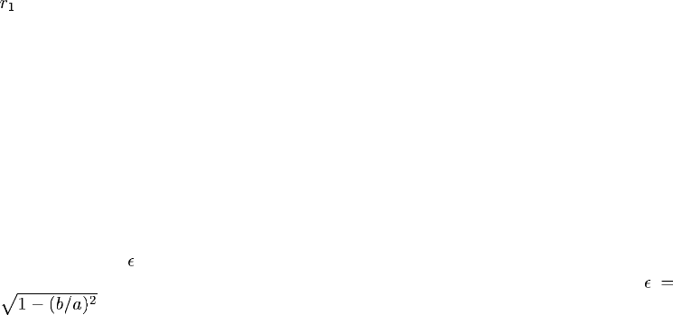
4. The eccentricity, , of the ellipse or prolate spheroid. The eccentricity is the square root of
one minus the square of the ratio of the semiminor axis, b, to the semimajor axis, a:
.
5. Global X-coordinate of the center of the ellipse or prolate spheroid defining the radiating
surface.
6. Global Y-coordinate of the center of the ellipse or prolate spheroid defining the radiating
surface.
7. Global Z-coordinate of the center of the ellipse or prolate spheroid defining the radiating
surface.
9.1–2
ABAQUS Version 6.1 Module: ID:
Printed on:
*IMPEDANCE
8. X-component of the direction cosine of the major axis of the ellipse or prolate spheroid defining
the radiating surface. The components of this vector need not be normalized to unit magnitude.
9. Y-component of the direction cosine of the major axis of the ellipse or prolate spheroid defining
the radiating surface.
10. Z-component of the direction cosine of the major axis of the ellipse or prolate spheroid defining
the radiating surface.
9.1–3
ABAQUS Version 6.1 Module: ID:
Printed on:
*IMPEDANCE PROPERTY
9.2 *IMPEDANCE PROPERTY: Define the impedance parameters for an acoustic medium
boundary.
This option is used to define the proportionality factors between the pressure and the normal components of
surface displacement and velocity in acoustic analysis. The *IMPEDANCE PROPERTY option must be used
in conjunction with the *IMPEDANCE or *SIMPEDANCE option.
Products: ABAQUS/Standard ABAQUS/Explicit
Type: Model data
Level: Model
References:
•“Acoustic loads,” Section 27.4.5 of the ABAQUS Analysis User’s Manual
•*IMPEDANCE
•*SIMPEDANCE
Required parameter:
NAME
Set this parameter equal to a label that will be used to refer to the impedance property on the
*IMPEDANCE or *SIMPEDANCE option.
Optional parameters:
DATA
Set DATA=ADMITTANCE (default) to specify an impedance using a table of admittance values.
Set DATA=IMPEDANCE to specify an impedance using a table of real and imaginary parts
of the impedance.
INPUT
Set this parameter equal to the name of the alternate input file containing the data lines for this
option. See “Input syntax rules,” Section 1.2.1 of the ABAQUS Analysis User’s Manual, for the
syntax of such file names. If this parameter is omitted, it is assumed that the data follow the keyword
line.
9.2–1
ABAQUS Version 6.1 Module: ID:
Printed on:
*IMPEDANCE PROPERTY
Data lines to define an impedance using DATA=ADMITTANCE (default):
First line:
1. , the proportionality factor between pressure and displacement of the surface in the normal
direction. This quantity is the imaginary part of the complex admittance, divided by the angular
frequency; see “Acoustic loads,” Section 27.4.5 of the ABAQUS Analysis User’s Manual.
(Units of F−1 L3.)
2. , the proportionality factor between pressure and velocity of the surface in the normal
direction. This quantity is the real part of the complex admittance. (Units of F−1 L3T−1 .)
3. Frequency. (Cycles/time.) Frequency dependence is active only during frequency domain
analysis in ABAQUS/Standard.
Repeat this data line as often as necessary in ABAQUS/Standard to describe the variation of the
coefficients with frequency. Only the first line entered will be used in direct-integration procedures.
Data lines to define an impedance using DATA=IMPEDANCE:
First line:
1. , the real part of the surface impedance. (Units of F L−3 T.)
2. , the imaginary part of the surface impedance. (Units of F L−3 T.)
3. Frequency. (Cycles/time.) Frequency dependence is active only during frequency domain
analysis in ABAQUS/Standard.
Repeat this data line as often as necessary in ABAQUS/Standard to describe the variation of the
coefficients with frequency. Only the first line entered will be used in direct-integration procedures.
9.2–2
ABAQUS Version 6.1 Module: ID:
Printed on:
*IMPERFECTION
9.3 *IMPERFECTION: Introduce geometric imperfections for postbuckling analysis.
This option is used to introduce a geometric imperfection into a model for a postbuckling analysis.
Products: ABAQUS/Standard ABAQUS/Explicit
Type: Model data
Level: Model
References:
•“Introducing a geometric imperfection into a model,” Section 11.3.1 of the ABAQUS Analysis User’s
Manual
•“Unstable collapse and postbuckling analysis,” Section 6.2.4 of the ABAQUS Analysis User’s Manual
•“Eigenvalue buckling prediction,” Section 6.2.3 of the ABAQUS Analysis User’s Manual
Optional parameters (mutually exclusive-if neither parameter is specified, ABAQUS assumes
that the imperfection data will be entered directly on the data lines):
FILE
Set this parameter equal to the name of the results file from a previous ABAQUS/Standard analysis
containing either the mode shapes from a *BUCKLE or *FREQUENCY analysis or the nodal
displacements from a *STATIC analysis.
INPUT
Set this parameter equal to the name of the alternate input file containing the imperfection data, in
general, as the node number and imperfection values in the global coordinate system. See “Input
syntax rules,” Section 1.2.1 of the ABAQUS Analysis User’s Manual, for the syntax of such file
names.
Required parameter if the FILE parameter is used:
STEP
Set this parameter equal to the step number (in the analysis whose results file is being used as input
to this option) from which the modal or displacement data are to be read.
Optional parameters if the FILE parameter is used:
INC
Set this parameter equal to the increment number (in the analysis whose results file is being used as
input to this option) from which the displacement data are to be read. If this parameter is omitted,
ABAQUS will read the data from the last increment available for the specified step on the results
file.
9.3–1
ABAQUS Version 6.1 Module: ID:
Printed on:
*IMPERFECTION
NSET
Set this parameter equal to the node set to which the geometric imperfection values are to be applied.
If this parameter is omitted, the imperfection will be applied to all nodes in the model.
Optional parameter if the FILE parameter is omitted:
SYSTEM
Set SYSTEM=R (default) to specify the imperfection as perturbation values of Cartesian
coordinates. Set SYSTEM=C to specify the imperfection as perturbation values of cylindrical
coordinates. Set SYSTEM=S to specify the imperfection as perturbation values of spherical
coordinates. See Figure 9.3–1.
The SYSTEM parameter is entirely local to this option and should not be confused with the
*SYSTEM option. As the data lines are read, the imperfection values specified are transformed
to the global rectangular Cartesian coordinate system. This transformation requires that the object
be centered about the origin of the global coordinate system; i.e., the *SYSTEM option should
be off when specifying imperfections as perturbation values using either cylindrical or spherical
coordinates.
Data lines to define the imperfection as a linear superposition of mode shapes from the results
file:
First line:
1. Mode number.
2. Scaling factor for this mode.
Repeat this data line as often as necessary to define the imperfection as a linear combination of mode
shapes.
Data line to define the imperfection based on the solution of a static analysis from the results file:
First (and only) line:
1. Set to 1.
2. Scaling factor.
Data lines to define the imperfection if the FILE and INPUT parameters are omitted:
First line:
1. Node number.
2. Component of imperfection in the first coordinate direction.
3. Component of imperfection in the second coordinate direction.
4. Component of imperfection in the third coordinate direction.
Repeat this data line as often as necessary to define the imperfection.
9.3–2
ABAQUS Version 6.1 Module: ID:
Printed on:

*IMPERFECTION
(X,Y,Z)
Rectangular Cartesian
(SYSTEM=R)
(default)
R
θ
Cylindrical
(SYSTEM=C)
(θ and φ are given in degrees)
(R,θ,φ)
θ
φ
Spherical
(SYSTEM=S)
Z
Y
X
YY
ZZ
X
X
(R,θ,Z)
Figure 9.3–1 Coordinate systems.
9.3–3
ABAQUS Version 6.1 Module: ID:
Printed on:
*IMPORT
9.4 *IMPORT: Import information from a previous ABAQUS/Explicit or
ABAQUS/Standard analysis.
If this is an ABAQUS/Explicit analysis, this option is used to define the time in a previous ABAQUS/Standard
analysis at which the specified node and element information is imported. If this is an ABAQUS/Standard
analysis, this option is used to define the time in a previous ABAQUS/Standard or ABAQUS/Explicit analysis
at which the specified node and element information is imported. The *IMPORToptionmustbeusedin
conjunction with the *INSTANCE option when importing a part instance from a previous analysis.
Products: ABAQUS/Standard ABAQUS/Explicit
Type: Model data
Level: Part instance
References:
•“Transferring results between ABAQUS analyses: overview,” Section 9.2.1 of the ABAQUS Analysis
User’s Manual
•*INSTANCE
Required parameter:
UPDATE
Set UPDATE=NO to continue the analysis without resetting the reference configuration.
Set UPDATE=YES to continue the analysis by resetting the reference configuration to be the
imported configuration. In this case displacement and strain values are calculated from the new
reference configuration.
Optional, mutually exclusive parameters:
INCREMENT
When importing an analysis from ABAQUS/Standard into ABAQUS/Explicit or from one
ABAQUS/Standard analysis into another ABAQUS/Standard analysis, set this parameter equal to
the increment of the specified step on the ABAQUS/Standard restart file from which the analysis
is to be imported. If this parameter is omitted, the analysis is imported from the last available
increment of the specified step.
INTERVAL
This parameter applies only to ABAQUS/Standard analyses.
When importing an analysis from ABAQUS/Explicit into ABAQUS/Standard, set this
parameter equal to the interval of the specified step on the ABAQUS/Explicit state file from which
9.4–1
ABAQUS Version 6.1 Module: ID:
Printed on:
*IMPORT
the analysis is to be imported. If this parameter is omitted, the analysis is imported from the last
available interval of the specified step.
ITERATION
This parameter is relevant only when the results are imported from a previous direct cyclic
ABAQUS/Standard analysis.
When importing an analysis from ABAQUS/Standard into ABAQUS/Explicit or from one
ABAQUS/Standard analysis into another ABAQUS/Standard analysis, set this parameter equal to
the iteration number of the specified step on the ABAQUS/Standard restart file from which the
analysis is to be imported. Since restart information can be written only at the end of an iteration in
a direct cyclic analysis, the INCREMENT parameter is irrelevant and is ignored if the ITERATION
parameter is specified. If this parameter is omitted, the analysis is imported from the last available
iteration of the specified step.
Optional parameters:
STATE
Set STATE=YES (default) to import the current material state of the elements at the specified step
and the specified interval, increment, or iteration.
Set STATE=NO if no material state is to be imported. In this case the elements will start with
no initial state or with the state as defined by the *INITIAL CONDITIONS option.
STEP
Set this parameter equal to the step on the ABAQUS/Explicit state file or on the ABAQUS/Standard
restart file from which the analysis is being imported. If this parameter is omitted, the analysis is
imported from the last available step on the state file or the restart file at the specified increment,
interval, or iteration.
Data lines to specify element sets to be imported:
First line:
1. List of element sets that are to be imported. Specify only element set names that are used
to define the section properties in the previous ABAQUS/Explicit or ABAQUS/Standard
analysis.
Repeat this data line as often as necessary to define the element sets to be imported. Up to 16 element
sets can be listed per data line.
There are no data lines for importing a part instance.
9.4–2
ABAQUS Version 6.1 Module: ID:
Printed on:
*IMPORT CONTROLS
9.5 *IMPORT CONTROLS: Specify tolerances used in importing model and results data.
This option is used to specify the tolerance for error checking on shell normals in ABAQUS/Standard or
ABAQUS/Explicit when the *IMPORT, UPDATE=YES option is used. If the *IMPORT CONTROLS option
is used, it must appear after the *IMPORT option.
Products: ABAQUS/Standard ABAQUS/Explicit
Type: Model data
Level: Model
References:
•“Transferring results between ABAQUS/Explicit and ABAQUS/Standard,” Section 9.2.2 of the
ABAQUS Analysis User’s Manual
•*IMPORT
Required parameter:
NORMAL TOL
Set this parameter equal to the tolerance required for the error checking on shell normals. The
default value is 0.1.
There are no data lines associated with this option.
9.5–1
ABAQUS Version 6.1 Module: ID:
Printed on:
*IMPORT ELSET
9.6 *IMPORT ELSET: Import element set definitions from a previous ABAQUS/Explicit or
ABAQUS/Standard analysis.
This option is used to import element set definitions that were defined in a previous ABAQUS/Explicit or
ABAQUS/Standard analysis. If the *IMPORT ELSET option is used, it must appear after the *IMPORT
option. If this option is omitted or is specified without any data lines, all the element sets relevant to the
analysis will be imported.
Products: ABAQUS/Standard ABAQUS/Explicit
Type: Model data
Level: Model
References:
•“Transferring results between ABAQUS/Explicit and ABAQUS/Standard,” Section 9.2.2 of the
ABAQUS Analysis User’s Manual
•*IMPORT
There are no parameters associated with this option.
Data lines to specify element set definitions to be imported:
First line:
1. List of element set names for which the element set definitions are to be imported.
Repeat this data line as often as necessary to specify the element set definitions to be imported. Up to
16 element sets can be listed per line.
9.6–1
ABAQUS Version 6.1 Module: ID:
Printed on:
*IMPORT NSET
9.7 *IMPORT NSET: Import node set definitions from a previous ABAQUS/Explicit or
ABAQUS/Standard analysis.
This option is used to import node set definitions that were defined in a previous ABAQUS/Explicit or
ABAQUS/Standard analysis. If the *IMPORT NSET option is used, it must appear after the *IMPORT
option. If this option is omitted or is specified without any data lines, all the node sets relevant to the analysis
will be imported.
Products: ABAQUS/Standard ABAQUS/Explicit
Type: Model data
Level: Model
References:
•“Transferring results between ABAQUS/Explicit and ABAQUS/Standard,” Section 9.2.2 of the
ABAQUS Analysis User’s Manual
•*IMPORT
There are no parameters associated with this option.
Data lines to specify node set definitions to be imported:
First line:
1. List of node set names for which the node set definitions are to be imported.
Repeat this data line as often as necessary to specify the node set definitions to be imported. Up to 16
node sets can be listed per line.
9.7–1
ABAQUS Version 6.1 Module: ID:
Printed on:
*INCIDENT WAVE
9.8 *INCIDENT WAVE: Define incident wave loading for a blast or scattering load on a
boundary.
The preferred interface for applying incident wave loading is the *INCIDENT WAVE INTERACTION
option used in conjunction with the *INCIDENT WAVE INTERACTION PROPERTY option. The
alternative interface uses the *INCIDENT WAVE option to apply incident wave loading. The alternative
interface will be removed in a subsequent release.
The *INCIDENT WAVE PROPERTY option must be used in conjunction with the *INCIDENT WAVE
option. If the incident wave field includes a reflection off a plane outside the boundaries of the mesh, this
effect can be modeled with the *INCIDENT WAVE REFLECTION option.
Products: ABAQUS/Standard ABAQUS/Explicit
Type: History data
Level: Step
References:
•“Acoustic, shock, and coupled acoustic-structural analysis,” Section 6.9.1 of the ABAQUS Analysis
User’s Manual
•“Acoustic loads,” Section 27.4.5 of the ABAQUS Analysis User’s Manual
•*INCIDENT WAVE PROPERTY
•*INCIDENT WAVE REFLECTION
Required parameter:
PROPERTY
Set this parameter equal to the name of the *INCIDENT WAVE PROPERTY option defining the
incident wave field.
Required, mutually exclusive parameters:
ACCELERATION AMPLITUDE
Set this parameter equal to the name of the amplitude curve defining the fluid particle acceleration
time history at the standoff point (“Amplitude curves,” Section 27.1.2 of the ABAQUS Analysis
User’s Manual). This amplitude curve will be used to compute the fluid traction only: a solid surface
requiring a pressure load cannot be specified on the data line of an *INCIDENT WAVE option if
the ACCELERATION AMPLITUDE parameter is used.
This parameter is valid only for planar incident waves using the *INCIDENT WAVE
PROPERTY, TYPE=PLANE option. Reflected loads, using the *INCIDENT WAVE
REFLECTION option, are not permitted in this case.
9.8–1
ABAQUS Version 6.1 Module: ID:
Printed on:
*INCIDENT WAVE
PRESSURE AMPLITUDE
Set this parameter equal to the name of the amplitude curve defining the fluid pressure time
history at the standoff point (“Amplitude curves,” Section 27.1.2 of the ABAQUS Analysis
User’s Manual). The corresponding fluid traction, if required, will be computed from the pressure
amplitude reference.
Data lines to define an incident wave:
First line:
1. Surface name.
2. Reference magnitude.
Repeat this data line as often as necessary to describe the loading on the surfaces due to the incident
wave. In problems involving fluid-solid boundaries, both the fluid surface and the solid surface comprising
the boundary must have an incident wave load specified, using the appropriate load type.
9.8–2
ABAQUS Version 6.1 Module: ID:
Printed on:

*INCIDENT WAVE FLUID PROPERTY
9.9 *INCIDENT WAVE FLUID PROPERTY: Define the fluid properties associated with an
incident wave.
The preferred interface for defining the fluid properties for an incident wave is the *INCIDENT WAVE
INTERACTION PROPERTY option used in conjunction with the *INCIDENT WAVE INTERACTION
option. The alternative interface uses the *INCIDENT WAVE FLUID PROPERTY option to define the fluid
properties used to define an incident wave. The alternative interface will be removed in a subsequent release.
The *INCIDENT WAVE FLUID PROPERTY must be used in conjunction with the *INCIDENT WAVE
PROPERTY option.
Products: ABAQUS/Standard ABAQUS/Explicit
Type: Model data
Level: Model
References:
•“Acoustic medium,” Section 20.3.1 of the ABAQUS Analysis User’s Manual
•“Acoustic loads,” Section 27.4.5 of the ABAQUS Analysis User’s Manual
•*INCIDENT WAVE PROPERTY
There are no parameters associated with this option.
Data line to define incident wave fluid properties:
First (and only) line:
1. , the fluid bulk modulus.
2. , the fluid mass density.
9.9–1
ABAQUS Version 6.1 Module: ID:
Printed on:
*INCIDENT WAVE INTERACTION
9.10 *INCIDENT WAVE INTERACTION: Define incident wave loading for a blast or
scattering load on a surface.
This option is used to apply incident wave loading. The *INCIDENT WAVE INTERACTION PROPERTY
option must be used in conjunction with the *INCIDENT WAVE INTERACTION option. If the incident
wave field includes a reflection off a plane outside the boundaries of the mesh, this effect can be modeled with
the *INCIDENT WAVE REFLECTION option.
Products: ABAQUS/Standard ABAQUS/Explicit
Type: History data
Level: Step
References:
•“Acoustic, shock, and coupled acoustic-structural analysis,” Section 6.9.1 of the ABAQUS Analysis
User’s Manual
•“Acoustic loads,” Section 27.4.5 of the ABAQUS Analysis User’s Manual
•*INCIDENT WAVE INTERACTION PROPERTY
•*INCIDENT WAVE REFLECTION
Required parameter:
PROPERTY
Set this parameter equal to the name of the *INCIDENT WAVE INTERACTION PROPERTY
option defining the incident wave field.
Required, mutually exclusive parameters:
ACCELERATION AMPLITUDE
Set this parameter equal to the name of the amplitude curve defining the fluid particle acceleration
time history at the standoff point (“Amplitude curves,” Section 27.1.2 of the ABAQUS Analysis
User’s Manual). This amplitude curve will be used to compute the fluid traction only: a solid
surface requiring a pressure load cannot be specified on the data line of an *INCIDENT WAVE
INTERACTION option if the ACCELERATION AMPLITUDE parameter is used.
This parameter is valid only for planar incident waves using the *INCIDENT WAVE
INTERACTION PROPERTY, TYPE=PLANE option. Reflected loads, using the *INCIDENT
WAVE REFLECTION option, are not permitted in this case.
9.10–1
ABAQUS Version 6.1 Module: ID:
Printed on:
*INCIDENT WAVE INTERACTION
PRESSURE AMPLITUDE
Set this parameter equal to the name of the amplitude curve defining the fluid pressure time
history at the standoff point (“Amplitude curves,” Section 27.1.2 of the ABAQUS Analysis
User’s Manual). The corresponding fluid traction, if required, will be computed from the pressure
amplitude reference.
UNDEX
Include this parameter to define a spherical incident wave using the *UNDEX CHARGE
PROPERTY option. This parameter is valid only for spherical incident waves using the
*INCIDENT WAVE INTERACTION PROPERTY, TYPE=SPHERE option.
Data line to define an incident wave:
First (and only) line:
1. Surface name.
2. The node number or set name of the source node.
3. The node number or set name of the standoff node.
4. Reference magnitude.
9.10–2
ABAQUS Version 6.1 Module: ID:
Printed on:

*INCIDENT WAVE INTERACTION PROPERTY
9.11 *INCIDENT WAVE INTERACTION PROPERTY: Define the geometric data and fluid
properties describing an incident wave.
This option defines the geometric data and fluid properties used to define incident waves. Each *INCIDENT
WAVE INTERACTION option must refer to an *INCIDENT WAVE INTERACTION PROPERTY definition.
Products: ABAQUS/Standard ABAQUS/Explicit
Type: Model data
Level: Model
References:
•“Acoustic loads,” Section 27.4.5 of the ABAQUS Analysis User’s Manual
•*INCIDENT WAVE INTERACTION
•*UNDEX CHARGE PROPERTY
Required parameter:
NAME
Set this parameter equal to a label that will be used to refer to the incident wave interaction property
in the *INCIDENT WAVE INTERACTION option.
Optional parameter:
TYPE
Set TYPE=PLANE (default) to specify a planar incident wave.
Set TYPE=SPHERE to specify a spherical incident wave.
Data line to define an incident wave interaction property:
First (and only) line:
1. , the speed of sound in the fluid, defining the rate of propagation of the wave.
2. , the fluid mass density.
9.11–1
ABAQUS Version 6.1 Module: ID:
Printed on:

*INCIDENT WAVE PROPERTY
9.12 *INCIDENT WAVE PROPERTY: Define the geometric data describing an incident
wave.
The preferred interface for defining the geometric data for an incident wave is the *INCIDENT WAVE
INTERACTION PROPERTY option used in conjunction with the *INCIDENT WAVE INTERACTION
option. The alternative interface uses the *INCIDENT WAVE PROPERTY option to define the geometric
data for incident waves. The alternative interface will be removed in a subsequent release.
Each *INCIDENT WAVE option must refer to an *INCIDENT WAVE PROPERTY definition. The
*INCIDENT WAVE PROPERTY option must be followed by the *INCIDENT WAVE FLUID PROPERTY
option, which defines the fluid properties used in the incident wave loading.
Products: ABAQUS/Standard ABAQUS/Explicit
Type: Model data
Level: Model
References:
•“Acoustic loads,” Section 27.4.5 of the ABAQUS Analysis User’s Manual
•*INCIDENT WAVE
•*INCIDENT WAVE FLUID PROPERTY
Required parameter:
NAME
Set this parameter equal to a label that will be used to refer to the incident wave property in the
*INCIDENT WAVE option.
Optional parameter:
TYPE
Set TYPE=PLANE (default) to specify a planar incident wave.
Set TYPE=SPHERE to specify a spherical incident wave.
Data lines to define an incident wave property:
First line:
1. X-coordinate of , the position of the incident wave standoff point.
2. Y-coordinate of , the position of the incident wave standoff point.
3. Z-coordinate of , the position of the incident wave standoff point.
9.12–1
ABAQUS Version 6.1 Module: ID:
Printed on:
*INCIDENT WAVE PROPERTY
4. X-component of , the velocity of the incident wave standoff point.
5. Y-component of , the velocity of the incident wave standoff point.
6. Z-component of , the velocity of the incident wave standoff point.
Second line:
1. X-coordinate of , the position of the incident wave source point. Alternatively, specify the
name of an *AMPLITUDE definition describing the time history of this coordinate.
2. Y-coordinate of , the position of the incident wave source point. Alternatively, specify the
name of an *AMPLITUDE definition describing the time history of this coordinate.
3. Z-coordinate of , the position of the incident wave source point. Alternatively, specify the
name of an *AMPLITUDE definition describing the time history of this coordinate.
If TYPE=PLANE, the vector from to defines the direction of the incoming wave; the distance
between the two points is unimportant. For incident wave loads using bubble amplitudes, the source
positions defined by the user with the *INCIDENT WAVE PROPERTY option are interpreted as
the initial positions of the source.
9.12–2
ABAQUS Version 6.1 Module: ID:
Printed on:
*INCIDENT WAVE REFLECTION
9.13 *INCIDENT WAVE REFLECTION: Define the reflection load on a surface caused by
incident wave fields.
This option is used to define reflected incident wave fields. It must be used in conjunction with the
*INCIDENT WAVE INTERACTION option (preferred interface for applying incident wave loading) or the
*INCIDENT WAVE option (alternative interface). The alternative interface will be removed in a subsequent
release.
Products: ABAQUS/Standard ABAQUS/Explicit
Type: History data
Level: Step
References:
•“Acoustic loads,” Section 27.4.5 of the ABAQUS Analysis User’s Manual
•*INCIDENT WAVE INTERACTION
•*INCIDENT WAVE
There are no parameters associated with this option.
Data lines to define an incident wave reflection:
First line:
1. Distance from the source point to the first reflecting plane.
2. X-direction cosine of the normal to the reflecting plane, pointing away from the source point.
3. Y-direction cosine of the normal to the reflecting plane, pointing away from the source point.
4. Z-direction cosine of the normal to the reflecting plane, pointing away from the source point.
5. Reflection coefficient.
Repeat this data line as often as necessary to describe the planes that reflect the incident wave.
9.13–1
ABAQUS Version 6.1 Module: ID:
Printed on:
*INCLUDE
9.14 *INCLUDE: Reference an external file containing ABAQUS input data.
This option is used to reference an external file containing a portion of the ABAQUS input file.
Products: ABAQUS/Standard ABAQUS/Explicit
Type: Model or history data
Level: Part, Part instance, Assembly, Model, Step
Reference:
•“Defining a model in ABAQUS,” Section 1.3.1 of the ABAQUS Analysis User’s Manual
Required parameter:
INPUT
Set this parameter equal to the name of the file containing the input data. See “Input syntax rules,”
Section 1.2.1 of the ABAQUS Analysis User’s Manual, for the syntax of such file names.
Optional parameter:
PASSW O RD
When the external file is encrypted, set this parameter equal to the file’s password. Passwords are
case-sensitive.
There are no data lines associated with this option.
9.14–1
ABAQUS Version 6.1 Module: ID:
Printed on:
*INCREMENTATION OUTPUT
9.15 *INCREMENTATION OUTPUT: Define output database requests for time
incrementation data.
This option is used to write incrementation variables to the output database. It must be used in conjunction
with the *OUTPUT, HISTORY option.
Product: ABAQUS/Explicit
Type: History data
Level: Step
References:
•“Output to the output database,” Section 4.1.3 of the ABAQUS Analysis User’s Manual
•*OUTPUT
Optional parameter:
VA R I A B L E
Set VARIABLE=ALL to indicate that all incrementation variables applicable to this procedure type
should be written to the output database.
Set VARIABLE=PRESELECT to indicate that the default incrementation output variables for
the current procedure type should be written to the output database. Additional output variables can
be requested on the data lines.
If this parameter is omitted, the incrementation variables requested for output must be specified
onthedatalines.
Data lines to request incrementation output:
First line:
1. Give the identifying keys for the variables to be written to the output database. The
keys are defined in “ABAQUS/Explicit output variable identifiers,” Section 4.2.2 of the
ABAQUS Analysis User’s Manual.
Repeat this data line as often as necessary to define the time incrementation variables to be written to
the output database.
9.15–1
ABAQUS Version 6.1 Module: ID:
Printed on:
*INELASTIC HEAT FRACTION
9.16 *INELASTIC HEAT FRACTION: Define the fraction of the rate of inelastic dissipation
that appears as a heat source.
This option is used to provide for inelastic energy dissipation to act as a heat source in adiabatic
thermo-mechanical problems. It is relevant when the ADIABATIC parameter is included on the *DYNAMIC
or the *STATIC option. It is also relevant when a fully coupled thermal-stress analysis is conducted using the
*COUPLED TEMPERATURE-DISPLACEMENT or *DYNAMIC TEMPERATURE-DISPLACEMENT
options.
Products: ABAQUS/Standard ABAQUS/Explicit
Type: Model data
Level: Model
References:
•“Adiabatic analysis,” Section 6.5.5 of the ABAQUS Analysis User’s Manual
•“Fully coupled thermal-stress analysis,” Section 6.5.4 of the ABAQUS Analysis User’s Manual
There are no parameters associated with this option.
Data line to define the inelastic heat fraction:
First (and only) line:
1. Fraction of inelastic dissipation rate that appears as a heat flux per unit volume. The fraction
may include a unit conversion factor if required. The default value is 0.9.
9.16–1
ABAQUS Version 6.1 Module: ID:
Printed on:
*INERTIA RELIEF
9.17 *INERTIA RELIEF: Apply inertia-based load balancing.
This option is used to apply inertia-based loads on a free or partially constrained body.
Product: ABAQUS/Standard
Type: History data
Level: Step
References:
•“Inertia relief,” Section 11.1.1 of the ABAQUS Analysis User’s Manual
•“Distributed loads,” Section 27.4.3 of the ABAQUS Analysis User’s Manual
Optional, mutually exclusive parameters:
FIXED
Include this parameter to indicate that the inertia relief load from a previous step should remain
fixed at its value from the beginning of the current step.
ORIENTATION
Set this parameter equal to the name given to the *ORIENTATION definition (“Orientations,”
Section 2.2.5 of the ABAQUS Analysis User’s Manual) that specifies the orientation of the local
system for rigid body degrees of freedom.
REMOVE
Include this parameter to indicate that the inertia relief load from a previous step should be removed
in the current step.
Optional data lines to specify global (or local, if the ORIENTATION parameter is used) degrees of
freedom that define the free directions along which inertia relief loads are applied:
First line:
1. Integer list of degrees of freedom identifying the free directions.
Second line (only needed to define a reference point for the rigid body direction vectors when the
user-chosen combination of free directions requires such a point):
1. Global X-coordinate of the reference point.
2. Global Y-coordinate of the reference point.
3. Global Z-coordinate of the reference point.
These data lines are needed only if rigid body motions are constrained in some directions.
9.17–1
ABAQUS Version 6.1 Module: ID:
Printed on:
*INERTIA RELIEF
There are no data lines when the FIXED or REMOVE parameters are specified.
9.17–2
ABAQUS Version 6.1 Module: ID:
Printed on:
*INITIAL CONDITIONS
9.18 *INITIAL CONDITIONS: Specify initial conditions for the model.
This option is used to prescribe initial conditions for an analysis.
Products: ABAQUS/Standard ABAQUS/Explicit ABAQUS/Aqua
Type: Model data
Level: Model
Reference:
•“Initial conditions,” Section 27.2.1 of the ABAQUS Analysis User’s Manual
Required parameters:
TYPE
Set TYPE=ACOUSTIC STATIC PRESSURE to define initial static pressure values at acoustic
nodes for use in evaluating the cavitation status of the acoustic element nodes in ABAQUS/Explicit.
Set TYPE=CONCENTRATION to give initial normalized concentrations for a mass diffusion
analysis in ABAQUS/Standard.
Set TYPE=CONTACT to specify initial bonded contact conditions on part of the slave surface
identified by a node set in an ABAQUS/Standard analysis.
Set TYPE=FIELD to specify initial values of field variables. The VARIABLE parameter can
be used with this parameter to define the field variable number. The STEP and INC parameters can
be used in conjunction with the FILE parameter to define initial values of field variables based on
the temperature record of a results file from a previous ABAQUS/Standard heat transfer analysis.
Set TYPE=FLUID PRESSURE to give initial pressures for hydrostatic fluid filled cavities.
Set TYPE=HARDENING to prescribe initial equivalent plastic strain and, if relevant, the
initial backstress tensor or to prescribe initial volumetric compacting plastic strain for the crushable
foam model. In ABAQUS/Standard the REBAR and USER parameters can be used with this
parameter. If the USER parameter is omitted, ABAQUS/Standard assumes that the initial conditions
are defined on the data lines.
Set TYPE=INITIAL GAP to identify the elements within which tangential fluid flow exists
initially.
Set TYPE=MASS FLOW RATE to specify initial values of mass flow rates in
ABAQUS/Standard heat transfer analyses involving forced convection modeled with the
forced convection/diffusion heat transfer elements.
Set TYPE=PLASTIC STRAIN to specify initial plastic strains. The SECTION POINTS
parameter can be used with this parameter. It is assumed that the plastic strain components are
defined on each data line in the order given for the element type, as defined in Part VI, “Elements,”
of the ABAQUS Analysis User’s Manual.
9.18–1
ABAQUS Version 6.1 Module: ID:
Printed on:
*INITIAL CONDITIONS
Set TYPE=PORE PRESSURE to give initial pore fluid pressures for a coupled pore fluid
diffusion/stress analysis in ABAQUS/Standard.
Set TYPE=POROSITY to give initial porosity values for materials defined with the *EOS
COMPACTION option in ABAQUS/Explicit.
Set TYPE=PRESSURE STRESS to give initial pressure stresses for a mass diffusion analysis
in ABAQUS/Standard. The STEP and INC parameters can be used in conjunction with the
FILE parameter to define initial values of pressure stress from the results file of a previous
ABAQUS/Standard stress/displacement analysis.
Set TYPE=RATIO to give initial void ratio values for a coupled pore fluid diffusion/stress
analysis in ABAQUS/Standard. The USER parameter can be used with this parameter to define
initial void ratio values in user subroutine VOIDRI.
Set TYPE=REF COORDINATE to define the reference mesh (initial metric) for membrane
elements in ABAQUS/Explicit. If a reference mesh is specified for an element, no initial stress or
strain can be specified for the same element. The initial stress and strain are computed automatically
to account for deformation from the reference to the initial configuration.
Set TYPE=RELATIVE DENSITY to give initial relative density values for materials defined
with the *POROUS METAL PLASTICITY option.
Set TYPE=ROTATING VELOCITY to prescribe initial velocities in terms of an angular
velocity and a global translational velocity.
Set TYPE=SATURATION to give initial saturation values for the analysis of flow through a
porous medium in ABAQUS/Standard. If no initial saturation values are given on this option, the
default is fully saturated conditions (saturation of 1.0). For partial saturation the initial saturation
and the pore fluid pressure must be consistent in the sense that the pore fluid pressure must lie within
the range of absorption and exsorption values for the initial saturation value. If this is not the case,
ABAQUS/Standard will adjust the saturation value as needed to satisfy this requirement.
Set TYPE=SOLUTION to give initial values of solution-dependent state variables. The
REBAR and, in ABAQUS/Standard, USER parameters can be used with this parameter. If
TYPE=SOLUTION is used without the USER parameter, element average quantities of the
solution-dependent state variables must be defined on each data line.
Set TYPE=SPECIFIC ENERGY to give initial specific energy values for materials defined
with the *EOS option in ABAQUS/Explicit.
Set TYPE=SPUD EMBEDMENT to give the initial embedment for a spud can in an
ABAQUS/Aqua analysis.
Set TYPE=SPUD PRELOAD to give the initial preload value for a spud can in an
ABAQUS/Aqua analysis.
Set TYPE=STRESS to give initial stresses. (These stresses are effective stresses when the
analysis includes pore fluid flow.) The GEOSTATIC; the REBAR; the SECTION POINTS; and,
in ABAQUS/Standard, the USER parameters can be used with this parameter. If TYPE=STRESS
is used without the USER parameter, it is assumed that the stress components are defined on
each data line in the order given for the element type, as defined in Part VI, “Elements,” of the
ABAQUS Analysis User’s Manual.
9.18–2
ABAQUS Version 6.1 Module: ID:
Printed on:
*INITIAL CONDITIONS
Set TYPE=TEMPERATURE to give initial temperatures. The STEP and INC parameters can
be used in conjunction with the FILE parameter to define initial temperatures from the results or
output database file of a previous ABAQUS/Standard heat transfer analysis.
Set TYPE=VELOCITY to prescribe initial velocities. Initial velocities should be defined in
the global directions, regardless of the use of the *TRANSFORM option.
STEP
This parameter is used only with the FILE parameter. The parameter specifies the step in the
results file of a previous ABAQUS analysis from which prescribed fields of TYPE=FIELD,
TYPE=PRESSURE STRESS, or TYPE=TEMPERATURE are to be read. It can also specify the
step in the output database file of a previous ABAQUS analysis from which prescribed fields of
TYPE=TEMPERATURE are to be read.
INC
This parameter is used only with the FILE parameter. The parameter specifies the increment in
the results file of a previous ABAQUS analysis from which prescribed fields of TYPE=FIELD,
TYPE=PRESSURE STRESS, or TYPE=TEMPERATURE are to be read. It can also specify the
increment in the output database file of a previous ABAQUS analysis from which prescribed fields
of TYPE=TEMPERATURE are to be read.
Optional parameters:
ABSOLUTE EXTERIOR TOLERANCE
This parameter is relevant only for use with the INTERPOLATE parameter. Set this parameter equal
to the absolute value (given in the units used in the model) by which nodes of the current model may
lie outside the region of the model in the output database specified by the FILE parameter. If this
parameter is not used or has a value of 0.0, the EXTERIOR TOLERANCE parameter will apply.
EXTERIOR TOLERANCE
This parameter is relevant only for use with the INTERPOLATE parameter. Set this parameter equal
to the fraction of the average element size by which nodes of the current model may lie outside the
region of the elements of the model in the output database specified by the FILE parameter. The
default value is 0.05.
If both tolerance parameters are specified, ABAQUS uses the tighter tolerance.
FILE
Set this parameter equal to the name of the results file from which initial field variable or pressure
stress data are to be read. Set this parameter equal to the name of the results file or output database
file from which initial temperature data are to be read. This parameter must be used in conjunction
with the STEP and INC parameters.
GEOSTATIC
This parameter is used only with TYPE=STRESS to specify that a geostatic stress state, in which
stresses vary with elevation only, is being defined.
9.18–3
ABAQUS Version 6.1 Module: ID:
Printed on:
*INITIAL CONDITIONS
INPUT
Set this parameter equal to the name of the alternate input file containing the data lines for this
option. See “Input syntax rules,” Section 1.2.1 of the ABAQUS Analysis User’s Manual, for the
syntax of such file names. If this parameter is omitted, it is assumed that the data follow the keyword
line.
INTERPOLATE
Include this parameter in conjunction with the FILE, STEP, and INC parameters to indicate that the
temperature field needs to be interpolated between dissimilar meshes. This feature is used to read
temperatures from an output database file generated during a heat transfer analysis. This parameter
and the MIDSIDE parameter are mutually exclusive. If the heat transfer analysis uses first-order
elements and the current mesh is the same but uses second-order elements, use the MIDSIDE
parameter instead.
MIDSIDE
This parameter applies only to ABAQUS/Standard analyses.
Include this parameter in conjunction with the FILE, STEP, and INC parameters to indicate
that midside node temperatures in second-order elements are to be interpolated from corner
node temperatures. This feature is used to read temperatures from a results or output database
file generated during a heat transfer analysis using first-order elements. This parameter and the
INTERPOLATE parameter are mutually exclusive.
NORMAL
This parameter applies only to ABAQUS/Standard analyses.
This parameter can be used only with TYPE=CONTACT to specify that the nodes in the node
set (or the contact pair, if a node set is not defined) are bonded only in the normal (contact) direction
and are allowed to move freely in the tangential direction. If the nodes in the node set (or the contact
pair) are to be bonded in all directions, this parameter should be omitted.
REBAR
This parameter can be used with TYPE=HARDENING in ABAQUS/Standard,
TYPE=SOLUTION, or TYPE=STRESS.
When used with TYPE=HARDENING in ABAQUS/Standard, it specifies that rebars are in a
work hardened state, with initial equivalent plastic strain and, possibly, initial backstress.
When used with TYPE=SOLUTION, it specifies that rebars are being assigned initial solution-
dependent state variable values.
When used with TYPE=STRESS, it specifies that prestress in rebars is being defined. When
performing an ABAQUS/Standard analysis, some iteration will usually be needed in this case
to establish a self-equilibrating stress state in the rebar and concrete. The *PRESTRESS HOLD
option can be useful for post-tensioning simulations (see “Defining rebar as an element property,”
Section 2.2.4 of the ABAQUS Analysis User’s Manual).
9.18–4
ABAQUS Version 6.1 Module: ID:
Printed on:
*INITIAL CONDITIONS
SECTION POINTS
This parameter is used only with TYPE=PLASTIC STRAIN, TYPE=STRESS, and
TYPE=HARDENING to specify plastic strains, stresses, and hardening variables at individual
section points through the thickness of a shell element. This parameter can be used only when shell
properties are defined using the *SHELL SECTION option. It cannot be used when properties
are defined using the *SHELL GENERAL SECTION option.
UNBALANCED STRESS
This parameter is used only with TYPE=STRESS.
Set UNBALANCED STRESS=RAMP (default) if the unbalanced stress is to be resolved
linearly over the step.
Set UNBALANCED STRESS=STEP if the unbalanced stress is to be resolved in the first
increment.
USER
This parameter applies only to ABAQUS/Standard analyses.
This parameter can be used with TYPE=HARDENING, TYPE=PORE PRESSURE,
TYPE=RATIO, TYPE=SOLUTION, or TYPE=STRESS.
When used with TYPE=HARDENING, it specifies that the initial conditions on equivalent
plastic strain and, if relevant, backstress tensor are to be given via user subroutine HARDINI.
When used with TYPE=PORE PRESSURE, it specifies that initial pore pressures are to be
given via user subroutine UPOREP.
When used with TYPE=RATIO, it specifies that initial void ratios are to be given via user
subroutine VOIDRI.
When used with TYPE=SOLUTION, it specifies that initial solution-dependent state variable
fields are to be given via user subroutine SDVINI.
When used with TYPE=STRESS, it specifies that stresses are to be given via user subroutine
SIGINI.
VA R I A B L E
ThisparameterisusedonlywithTYPE=FIELDwhenitisusedtodefinethefieldvariablenumber.
The default is VARIABLE=1. Any number of separate field variables can be used: each must be
numbered consecutively (1, 2, 3, etc.)
Data line for TYPE=ACOUSTIC STATIC PRESSURE:
First (and only) line:
1. Node set or node number.
2. Hydrostatic pressure at the first reference point.
3. X-coordinate of the first reference point.
4. Y-coordinate of the first reference point.
5. Z-coordinate of the first reference point.
6. Hydrostatic pressure at the second reference point.
9.18–5
ABAQUS Version 6.1 Module: ID:
Printed on:
*INITIAL CONDITIONS
7. X-coordinate of the second reference point.
8. Y-coordinate of the second reference point.
9. Z-coordinate of the second reference point.
Data lines for TYPE=CONCENTRATION:
First line:
1. Node set or node number.
2. Initial normalized concentration value at the node.
Repeat this data line as often as necessary to define the initial normalized concentration at various nodes
or node sets.
Data lines for TYPE=CONTACT:
First line:
1. Slave surface name.
2. Master surface name.
3. Name of the node set associated with the slave surface.
Repeat this data line as often as necessary to define partially bonded surfaces.
Data lines for TYPE=FIELD, VARIABLE=n:
First line:
1. Node set or node number.
2. Initial value of this field variable at the first temperature point. For shells and beams several
values (or a value and the field variable gradients across the section) can be given at each node
(see “Beam modeling: overview,” Section 23.3.1 of the ABAQUS Analysis User’s Manual, as
well as “Shell elements: overview,” Section 23.6.1 of the ABAQUS Analysis User’s Manual).
For heat transfer shells the field variables at each temperature point through the shell thickness
must be specified. The number of values depends on the (maximum) number of points specified
on the data lines associated with the *SHELL SECTION options.
3. Initial value of this field variable at the second temperature point.
4. Etc., up to seven values.
Subsequent lines (only needed if initial values must be specified at more than seven temperature
points at any node):
1. Eighth initial value of this field variable at this temperature point.
2. Etc., up to eight initial values per line.
It may be necessary to leave blank data lines for some nodes if any other node in the model has more
than seven field variable points because the total number of field variables that ABAQUS expects
9.18–6
ABAQUS Version 6.1 Module: ID:
Printed on:
*INITIAL CONDITIONS
to read for any node is based on the maximum number of field variable values for all the nodes in
the model. These trailing initial values will be zero and will not be used in the analysis.
Repeat this set of data lines as often as necessary to define initial temperatures at various nodes or node
sets.
No data lines are required for TYPE=FIELD, VARIABLE=n,FILE=file,STEP=step,INC=inc.
Data lines for TYPE=FLUID PRESSURE:
First line:
1. Node set or node number of fluid cavity reference node.
2. Fluid pressure.
Repeat this data line as often as necessary to define initial fluid pressure for various fluid-filled cavities.
Data lines to prescribe initial equivalent plastic strain or backstresses using TYPE=HARDENING
if the REBAR, SECTION POINTS, and USER parameters are omitted:
First line:
1. Element number or element set label.
2. Initial equivalent plastic strain, .
3. First value of the initial backstress, . (Only relevant for the kinematic hardening models.)
4. Second value of the initial backstress, . (Only relevant for the kinematic hardening models.)
5. Etc., up to six backstress components. (Only relevant for the kinematic hardening models.)
Give the backstress components as defined for this element type in Part VI, “Elements,” of the
ABAQUS Analysis User’s Manual. Values given on the data lines are applied uniformly over the
element. In any element for which an *ORIENTATION option applies, backstresses must be given
in the local system (“Orientations,” Section 2.2.5 of the ABAQUS Analysis User’s Manual).
Repeat this data line as often as necessary to define the hardening parameters for various elements or
element sets.
Data lines to prescribe initial volumetric compacting plastic strain for the crushable foam model
using TYPE=HARDENING:
First line:
1. Element number or element set label.
2. Initial volumetric compacting plastic strain, .
Repeat this data line as often as necessary to define the initial volumetric compacting plastic strain for
various elements or element sets.
9.18–7
ABAQUS Version 6.1 Module: ID:
Printed on:
*INITIAL CONDITIONS
Data lines for TYPE=HARDENING, REBAR:
First line:
1. Element number or element set label.
2. Rebar name. If this field is left blank, the initial conditions will be applied to all rebars in the
model.
3. Initial equivalent plastic strain, .
4. Initial backstress, . (Only relevant for the kinematic hardening models.)
Repeat this data line as often as necessary to define the hardening parameters for rebars in various
elements or element sets.
No data lines are required for TYPE=HARDENING, USER.
Data lines for TYPE=HARDENING, SECTION POINTS:
First line:
1. Element number or element set label.
2. Section point number.
3. Initial equivalent plastic strain, .
4. First value of the initial backstress, . (Only relevant for the kinematic hardening models.)
5. Second value of the initial backstress, . (Only relevant for the kinematic hardening models.)
6. Third value of the initial backstress, . (Only relevant for the kinematic hardening models.)
Give the backstress components as defined for this element type in Part VI, “Elements,” of the
ABAQUS Analysis User’s Manual. In any element for which an *ORIENTATION option applies,
the backstress components must be given in the local system (“Orientations,” Section 2.2.5 of the
ABAQUS Analysis User’s Manual).
Repeat this data line as often as necessary to define the hardening parameters in various elements or
element sets. The hardening parameters must be defined at all section points within an element.
Data lines for TYPE=INITIAL GAP:
First line:
1. Element number or element set label.
Repeat this data line as often as necessary to identify various elements or element sets.
Data lines for TYPE=MASS FLOW RATE:
First line:
1. Node set or node number.
9.18–8
ABAQUS Version 6.1 Module: ID:
Printed on:

*INITIAL CONDITIONS
2. Initial mass flow rate per unit area in the x-direction or total initial mass flow rate in the cross-
section for one-dimensional elements.
3. Initial mass flow rate per unit area in the y-direction (not needed for nodes associated with
one-dimensional convective flow elements).
4. Initial mass flow rate per unit area in the z-direction (not needed for nodes associated with
one-dimensional convective flow elements).
Repeat this data line as often as necessary to define mass flow rates at various nodes or node sets.
Data lines to prescribe initial plastic strains using TYPE=PLASTIC STRAIN if the REBAR and
SECTION POINTS parameters are omitted:
First line:
1. Element number or element set label.
2. Value of first plastic strain component, .
3. Value of second plastic strain component, .
4. Etc., up to six plastic strain components.
Give the plastic strain components as defined for this element type in Part VI, “Elements,” of the
ABAQUS Analysis User’s Manual. Values given on the data lines are applied uniformly over the
element. In any element for which an *ORIENTATION option applies, the plastic strains must be
given in the local system (“Orientations,” Section 2.2.5 of the ABAQUS Analysis User’s Manual).
Repeat this data line as often as necessary to define initial plastic strains in various elements or element
sets.
Data lines for TYPE=PLASTIC STRAIN, REBAR:
First line:
1. Element number or element set label.
2. Rebar name. If this field is left blank, the initial conditions will be applied to all rebars in the
model.
3. Initial plastic strain value.
Repeat this data line as often as necessary to define the initial plastic strain in the rebars of various
elements or element sets.
Data lines for TYPE=PLASTIC STRAIN, SECTION POINTS:
First line:
1. Element number or element set label.
2. Section point number.
3. Value of first plastic strain component, .
4. Value of second plastic strain component, .
9.18–9
ABAQUS Version 6.1 Module: ID:
Printed on:
*INITIAL CONDITIONS
5. Value of third plastic strain component, .
Give the initial plastic strain components as defined for this element type in Part VI, “Elements,”
of the ABAQUS Analysis User’s Manual. In any element for which an *ORIENTATION
option applies, the plastic strain components must be given in the local system (“Orientations,”
Section 2.2.5 of the ABAQUS Analysis User’s Manual).
Repeat this data line as often as necessary to define initial plastic strains in various elements or element
sets. Plastic strains must be defined at all section points within an element.
Data lines for TYPE=PORE PRESSURE if the USER parameter is omitted:
First line:
1. Node set or node number.
2. First value of fluid pore pressure, .
3. Vertical coordinate corresponding to the above value.
4. Second value of fluid pore pressure, .
5. Vertical coordinate corresponding to the above value.
Omit the elevation values and the second pore pressure value to define a constant pore pressure
distribution.
Repeat this data line as often as necessary to define the fluid pore pressure at various nodes or node
sets.
No data lines are required for TYPE=PORE PRESSURE, USER.
Data lines for TYPE=POROSITY:
First line:
1. Element number or element set label.
2. Initial porosity.
Repeat this data line as often as necessary to define initial porosity in various elements or element sets.
Data lines for TYPE=PRESSURE STRESS:
First line:
1. Node set or node number.
2. Equivalent pressure stress, p.
Repeat this data line as often as necessary to define the pressure stress at various nodes or node sets.
9.18–10
ABAQUS Version 6.1 Module: ID:
Printed on:
*INITIAL CONDITIONS
No data lines are required for TYPE=PRESSURE STRESS, FILE=file, STEP=step, INC=inc.
Data lines for TYPE=RATIO if the USER parameter is omitted:
First line:
1. Node set or node number.
2. First value of void ratio.
3. Vertical coordinate corresponding to the above value.
4. Second value of void ratio.
5. Vertical coordinate corresponding to the above value.
Omit the elevation values and the second void ratio value to define a constant void ratio distribution.
Repeat this data line as often as necessary to define void ratios at various nodes or node sets.
No data lines are required for TYPE=RATIO, USER.
Data lines for TYPE=REF COORDINATE:
First line:
1. Element number.
2. X-coordinate of the first node.
3. Y-coordinate of the first node.
4. Z-coordinate of the first node.
5. X-coordinate of the second node.
6. Y-coordinate of the second node.
7. Z-coordinate of the second node.
Second line:
1. X-coordinate of the third node.
2. Y-coordinate of the third node.
3. Z-coordinate of the third node.
4. X-coordinate of the fourth node.
5. Y-coordinate of the fourth node.
6. Z-coordinate of the fourth node.
Repeat this pair of data lines as often as necessary to define the reference mesh in various elements.
The order of the nodal coordinates must be consistent with the element connectivity.
9.18–11
ABAQUS Version 6.1 Module: ID:
Printed on:
*INITIAL CONDITIONS
Data lines for TYPE=RELATIVE DENSITY:
First line:
1. Node set or node number.
2. Initial relative density.
Repeat this data line as often as necessary to define initial relative density at various nodes or node sets.
Data lines for TYPE=ROTATING VELOCITY:
First line:
1. Node set or node number.
2. Angular velocity about the axis defined from point ato point b, where the coordinates of aand
bare given below.
3. Global X-component of translational velocity.
4. Global Y-component of translational velocity.
5. Global Z-component of translational velocity.
Second line:
1. Global X-component of point aon the axis of rotation.
2. Global Y-component of point aon the axis of rotation.
3. Global Z-component of point aon the axis of rotation.
4. Global X-component of point bon the axis of rotation.
5. Global Y-component of point bon the axis of rotation.
6. Global Z-component of point bon the axis of rotation.
Repeat this pair of data lines as often as necessary to define the angular and translational velocities at
various nodes or node sets.
Data lines for TYPE=SATURATION:
First line:
1. Node set or node number.
2. Saturation value, s. Default is 1.0.
Repeat this data line as often as necessary to define saturation at various nodes or node sets.
Data lines for TYPE=SOLUTION if the USER and REBAR parameters are omitted:
First line:
1. Element number or element set label.
2. Value of first solution-dependent state variable.
3. Value of second solution-dependent state variable.
4. Etc., up to seven solution-dependent state variables.
9.18–12
ABAQUS Version 6.1 Module: ID:
Printed on:
*INITIAL CONDITIONS
Subsequent lines (only needed if more than seven solution-dependent state variables exist in the model):
1. Value of eighth solution-dependent state variable.
2. Etc., up to eight solution-dependent state variables per line.
It may be necessary to leave blank data lines for some elements if any other element in the model
has more solution-dependent state variables because the total number of variables that ABAQUS
expects to read for any element is based on the maximum number of solution-dependent state
variables for all the elements in the model. These trailing initial values will be zero and will not be
used in the analysis. Values given on the data lines will be applied uniformly over the element.
Repeat this set of data lines as often as necessary to define initial values of solution-dependent state
variables for various elements or element sets.
Data lines for TYPE=SOLUTION, REBAR:
First line:
1. Element number or element set label.
2. Rebar name. If this field is left blank, the solution-dependent state variables are applied to all
rebars in these elements.
3. Value of first solution-dependent state variable.
4. Value of second solution-dependent state variable.
5. Etc., up to six solution-dependent state variables.
Subsequent lines (only needed if more than six solution-dependent state variables exist in the model):
1. Value of seventh solution-dependent state variable.
2. Etc., up to eight solution-dependent state variables per line.
It may be necessary to leave blank data lines for some elements if any other element in the model
has more solution-dependent state variables because the total number of variables that ABAQUS
expects to read for any element is based on the maximum number of solution-dependent state
variables for all the elements in the model. These trailing initial values will be zero and will not be
used in the analysis. Values given on the data lines will be applied uniformly over the element.
Repeat this set of data lines as often as necessary to define initial values of solution-dependent state
variables for various elements or element sets.
No data lines are required for TYPE=SOLUTION, USER.
Data lines for TYPE=SPECIFIC ENERGY:
First line:
1. Element number or element set label.
9.18–13
ABAQUS Version 6.1 Module: ID:
Printed on:
*INITIAL CONDITIONS
2. Initial specific energy.
Repeat this data line as often as necessary to define initial specific energy in various elements or element
sets.
Data lines for TYPE=SPUD EMBEDMENT:
First line:
1. Element set or element number.
2. Spud can embedment, .
Repeat this data line as often as necessary to define initial embedment for various elements or element
sets.
Data lines for TYPE=SPUD PRELOAD:
First line:
1. Element set or element number.
2. Spud can preload, .
Repeat this data line as often as necessary to define initial preload for various elements or element sets.
Data lines for TYPE=STRESS if the GEOSTATIC, REBAR, SECTION POINTS, and USER
parameters are omitted:
First line:
1. Element number or element set label.
2. Value of first (effective) stress component, axial force when used with the *BEAM GENERAL
SECTION or *FRAME SECTION options, or direct membrane force per unit width in the local
1-direction when used with the *SHELL GENERAL SECTION option.
3. Value of second stress component.
4. Etc., up to six stress components.
Give the stress components as defined for this element type in Part VI, “Elements,” of the
ABAQUS Analysis User’s Manual. Stress values given on data lines are applied uniformly and
equally over all integration points of the element. In any element for which an *ORIENTATION
option applies, the stresses must be given in the local system (“Orientations,” Section 2.2.5 of the
ABAQUS Analysis User’s Manual).
Repeat this data line as often as necessary to define initial stresses in various elements or element sets.
Data lines for TYPE=STRESS, GEOSTATIC:
First line:
1. Element number or element set label.
2. First value of vertical component of (effective) stress.
9.18–14
ABAQUS Version 6.1 Module: ID:
Printed on:
*INITIAL CONDITIONS
3. Vertical coordinate corresponding to the above value.
4. Second value of vertical component of (effective) stress.
5. Vertical coordinate corresponding to the above value.
6. First coefficient of lateral stress. This coefficient defines the x-direction stress components.
7. Second coefficient of lateral stress. This coefficient defines the y-direction stress component
in three-dimensional cases and the thickness or hoop direction component in plane or
axisymmetric cases. If this value is omitted, it is assumed to be the same as the first lateral
stress coefficient given in the previous field.
Repeat this data line as often as necessary to define an initial geostatic stress state in various elements
or element sets.
Data lines for TYPE=STRESS, REBAR:
First line:
1. Element number or element set label.
2. Rebar name. If this field is left blank, the stress is applied to all rebars in these elements.
3. Prestress value.
Repeat this data line as often as necessary to define initial stress in the rebars of various elements or
element sets.
Data lines for TYPE=STRESS, SECTION POINTS:
First line:
1. Element number or element set label.
2. Section point number.
3. Value of first stress component.
4. Value of second stress component.
5. Etc., up to three stress components.
Give the stress components as defined for this element type in Part VI, “Elements,” of the
ABAQUS Analysis User’s Manual. Stress values given on data lines are applied uniformly over
the element. In any element for which an *ORIENTATION option applies, the stresses must be
given in the local system (“Orientations,” Section 2.2.5 of the ABAQUS Analysis User’s Manual).
Repeat this data line as often as necessary to define initial stresses in various elements or element sets.
Stresses must be defined at all section points within an element.
9.18–15
ABAQUS Version 6.1 Module: ID:
Printed on:
*INITIAL CONDITIONS
No data lines are required for TYPE=STRESS, USER.
Data lines for TYPE=TEMPERATURE:
First line:
1. Node set or node number.
2. First initial temperature value at the node or node set. For shells and beams several values
(or a value and the temperature gradients across the section) can be given at each node
(see “Using a beam section integrated during the analysis to define the section behavior,”
Section 23.3.6 of the ABAQUS Analysis User’s Manual; “Using a general beam section to
define the section behavior,” Section 23.3.7 of the ABAQUS Analysis User’s Manual; “Using
a shell section integrated during the analysis to define the section behavior,” Section 23.6.5
of the ABAQUS Analysis User’s Manual; and “Using a general shell section to define the
section behavior,” Section 23.6.6 of the ABAQUS Analysis User’s Manual). For heat transfer
shells the temperature at each point through the shell thickness must be specified. The number
of values depends on the (maximum) number of points specified on the data lines associated
with the *SHELL SECTION options.
3. Second initial temperature value at the node or node set.
4. Etc., up to seven initial temperature values at this node or node set.
Subsequent lines (only needed if there are more than seven temperature values at any node):
1. Eighth initial temperature value at this node or node set.
2. Etc., up to eight initial temperature values per line.
If more than seven temperature values are needed at any node, continue on the next line. It may
be necessary to leave blank data lines for some nodes if any other node in the model has more than
seven temperature points because the total number of temperatures that ABAQUS expects to read
for any node is based on the maximum number of temperature values of all the nodes in the model.
These trailing initial values will be zero and will not be used in the analysis.
Repeat this data line (or set of lines) as often as necessary to define initial temperatures at various nodes
or node sets.
No data lines are required for TYPE=TEMPERATURE, FILE=file,STEP=step,INC=inc.
No data lines are required for TYPE=TEMPERATURE, MIDSIDE, FILE=file,STEP=step,INC=inc.
No data lines are required for TYPE=TEMPERATURE, INTERPOLATE, FILE=file,STEP=step,
INC=inc.
9.18–16
ABAQUS Version 6.1 Module: ID:
Printed on:
*INITIAL CONDITIONS
Data lines for TYPE=VELOCITY:
First line:
1. Node set or node number.
2. Degree of freedom.
3. Value of initial velocity.
Repeat this data line as often as necessary to define the initial velocity at various nodes or node sets.
9.18–17
ABAQUS Version 6.1 Module: ID:
Printed on:
*INSTANCE
9.19 *INSTANCE: Begin an instance definition.
This option is used to instance a part within an assembly. It must be used in conjunction with the *ASSEMBLY
and *END INSTANCE options. If the instance is not imported from a previous analysis, the *INSTANCE
option must be used in conjunction with the *PART option. When importing a part instance from a previous
analysis, the *INSTANCE option must be used in conjunction with the *IMPORT option.
Products: ABAQUS/Standard ABAQUS/Explicit
Type: Model data
Level: Assembly
References:
•“Defining an assembly,” Section 2.9.1 of the ABAQUS Analysis User’s Manual
•“Transferring results between ABAQUS analyses: overview,” Section 9.2.1 of the ABAQUS Analysis
User’s Manual
•*END INSTANCE
•*IMPORT
Required parameters if the instance is not imported from a previous analysis:
NAME
Set this parameter equal to a label that will be used to refer to the instance.
PART
Set this parameter equal to the name of the part being instanced.
Required parameter if the instance is to be imported from a previous analysis:
INSTANCE
Set this parameter equal to the name of the instance to be imported from the previous analysis.
Optional import parameter:
LIBRARY
Set this parameter equal to the name of the previous analysis from which the instance should
be imported. The previous analysis output database (.odb) file should reside in the current
(working) directory. If the LIBRARY parameter is omitted, the job name of the previous analysis
must be specified on the command line using the oldjob parameter (see “Execution procedure
for ABAQUS/Standard and ABAQUS/Explicit,” Section 3.2.2 of the ABAQUS Analysis User’s
Manual). If both methods are used, the command line specification will take precedence over the
LIBRARY parameter.
9.19–1
ABAQUS Version 6.1 Module: ID:
Printed on:
*INSTANCE
Data line to translate an instance that is not imported from a previous analysis:
First (and only) line:
1. Value of the translation to be applied in the X-direction.
2. Value of the translation to be applied in the Y-direction.
3. Value of the translation to be applied in the Z-direction.
Data lines to translate and/or rotate an instance that is not imported from a previous analysis:
First line:
1. Value of the translation to be applied in the X-direction.
2. Value of the translation to be applied in the Y-direction.
3. Value of the translation to be applied in the Z-direction.
Enter values of zero to apply a pure rotation.
Second line:
1. X-coordinate of point aon the axis of rotation (see Figure 9.19–1).
2. Y-coordinate of point aon the axis of rotation.
3. Z-coordinate of point aon the axis of rotation.
4. X-coordinate of point bon the axis of rotation.
5. Y-coordinate of point bon the axis of rotation.
6. Z-coordinate of point bon the axis of rotation.
7. Angle of rotation about the axis a–b, in degrees.
If both translation and rotation are specified, translation is applied before rotation.
There are no data lines for an instance that is imported from a previous analysis.
9.19–2
ABAQUS Version 6.1 Module: ID:
Printed on:
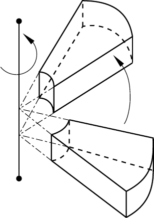
*INSTANCE
θ
a
b
θ
Figure 9.19–1 Rotation of an instance.
9.19–3
ABAQUS Version 6.1 Module: ID:
Printed on:
*INTEGRATED OUTPUT
9.20 *INTEGRATED OUTPUT: Specify variables integrated over a surface to be written to
the output database.
This option is used to write integrated quantities over a surface, such as the total force transmitted across a
surface, to the output database. It must be used in conjunction with the *OUTPUT, HISTORY option.
Product: ABAQUS/Explicit
Type: History data
Level: Step
References:
•“Output to the output database,” Section 4.1.3 of the ABAQUS Analysis User’s Manual
•“Integrated output section definition,” Section 2.5.1 of the ABAQUS Analysis User’s Manual
•*OUTPUT
•*SURFACE
•*INTEGRATED OUTPUT SECTION
Required, mutually exclusive parameters:
SECTION
Set this parameter equal to the name of the *INTEGRATED OUTPUT SECTION (see “Integrated
output section definition,” Section 2.5.1 of the ABAQUS Analysis User’s Manual) over which this
output request is being made.
SURFACE
Set this parameter equal to the name of the surface (see “Defining element-based surfaces,”
Section 2.3.2 of the ABAQUS Analysis User’s Manual) over which this output request is being
made.
Optional parameter:
VA R I A B L E
Set VARIABLE=ALL to indicate that all integrated output variables applicable to this procedure
should be written to the output database.
Set VARIABLE=PRESELECT to indicate that the default integrated output variables for the
current procedure type should be written to the output database. Additional output variables can be
requestedonthedatalines.
If this parameter is omitted, the integrated output variables for output must be specified on the
data line.
9.20–1
ABAQUS Version 6.1 Module: ID:
Printed on:
*INTEGRATED OUTPUT
Data lines to request integrated output:
First line:
1. Specify the identifying keys for the output variables to be written to the output database.
The keys are defined in “ABAQUS/Explicit output variable identifiers,” Section 4.2.2 of the
ABAQUS Analysis User’s Manual.
Repeat this data line as often as necessary to define the list of variables to be written to the output
database.
9.20–2
ABAQUS Version 6.1 Module: ID:
Printed on:
*INTEGRATED OUTPUT SECTION
9.21 *INTEGRATED OUTPUT SECTION: Define an integrated output section over a surface
with a local coordinate system and a reference point.
This option is used to associate a surface with a coordinate system and/or a reference node to track the average
motion of the surface. It can also be used in conjunction with an integrated output request to obtain output of
quantities integrated over a surface.
Product: ABAQUS/Explicit
Type: Model data
Level: Part, Part instance, Assembly
References:
•“Integrated output section definition,” Section 2.5.1 of the ABAQUS Analysis User’s Manual
•“Output to the output database,” Section 4.1.3 of the ABAQUS Analysis User’s Manual
•*INTEGRATED OUTPUT
•*SURFACE
Required parameters:
NAME
Set this parameter equal to a label that will be used to refer to the integrated output section.
SURFACE
Set this parameter equal to the name of the surface (see “Defining element-based surfaces,”
Section 2.3.2 of the ABAQUS Analysis User’s Manual) to be associated with the integrated output
section.
Optional parameters:
ORIENTATION
Set this parameter equal to the name of an orientation definition (“Orientations,” Section 2.2.5 of
the ABAQUS Analysis User’s Manual) to define the initial coordinate system for the section. This
initial system can be further modified by using the PROJECT ORIENTATION parameter.
If this parameter is omitted, the global coordinate system is used.
POSITION
This parameter is relevant only if the REF NODE parameter is included.
Set POSITION=INPUT (default) if the location of the reference node is to be defined by the
user.
9.21–1
ABAQUS Version 6.1 Module: ID:
Printed on:
*INTEGRATED OUTPUT SECTION
Set POSITION=CENTER if the reference node is to be relocated from the user-defined location
to the center of the surface in the initial configuration.
PROJECT ORIENTATION
Set PROJECT ORIENTATION=NO (default) if the initial coordinate system of the section should
not be projected onto the section surface. If the ORIENTATION parameter is included, this choice
results in an initial coordinate system that matches the defined orientation. If an orientation is not
specified, the initial coordinate system matches the global coordinate system.
Set PROJECT ORIENTATION=YES if the initial coordinate system of the section should
be modified by projecting onto the section surface using the average normal to the surface. If an
orientation is not specified, the global coordinate system is projected onto the section surface.
REF NODE
Set this parameter equal to either the node number of the integrated output section reference node
or to the name of a node set containing the reference node. If the name of a node set is chosen, the
node set must contain exactly one node.
REF NODE MOTION
This parameter is relevant only if the REF NODE parameter is included.
Set REF NODE MOTION=INDEPENDENT (default) if the motion of the reference node is
not based on the average motion of the surface.
Set REF NODE MOTION=AVERAGE TRANSLATION if the reference node must translate
with the average translation of the surface. This choice is relevant only if the reference node is not
connected to the rest of the model.
Set REF NODE MOTION=AVERAGE if the reference node must both translate and rotate
with the average motion of the surface. This choice is relevant only if the reference node is not
connected to the rest of the model.
There are no data lines associated with this option.
9.21–2
ABAQUS Version 6.1 Module: ID:
Printed on:
*INTERACTION OUTPUT
9.22 *INTERACTION OUTPUT: Specify spot weld interaction variables to be written to the
output database.
This option is used to write spot weld interaction variables to the output database. It must be used in
conjunction with the *OUTPUT, HISTORY option.
Products: ABAQUS/Standard ABAQUS/Explicit
Type: History data
Level: Step
References:
•“Output to the output database,” Section 4.1.3 of the ABAQUS Analysis User’s Manual
•“Mesh-independent fasteners,” Section 28.3.4 of the ABAQUS Analysis User’s Manual
•*OUTPUT
Required, mutually exclusive parameters:
NAME
Set this parameter equal to the name of the spot weld interaction for which this output request is
being made.
NSET
Set this parameter equal to the name of the node set for which this output request is being made.
Data lines to request spot weld interaction output to the output database:
First line:
1. Specify the identifying keys for the output variables to be written to the output database.
The keys are defined in “ABAQUS/Standard output variable identifiers,” Section 4.2.1 of
the ABAQUS Analysis User’s Manual, and “ABAQUS/Explicit output variable identifiers,”
Section 4.2.2 of the ABAQUS Analysis User’s Manual.
Repeat this data line as often as necessary to define the list of variables to be written to the output
database.
9.22–1
ABAQUS Version 6.1 Module: ID:
Printed on:
*INTERACTION PRINT
9.23 *INTERACTION PRINT: Define print requests for spot weld interaction variables.
This option is used to provide tabular printed output of spot weld interaction variables.
Product: ABAQUS/Standard
Type: History data
Level: Step
References:
•“Output to the data and results files,” Section 4.1.2 of the ABAQUS Analysis User’s Manual
•“Mesh-independent fasteners,” Section 28.3.4 of the ABAQUS Analysis User’s Manual
Optional, mutually exclusive parameters:
NAME
Set this parameter equal to the name of the spot weld interaction for which this output request is
being made.
NSET
Set this parameter equal to the name of the node set for which this output request is being made.
Optional parameters:
FREQUENCY
Set this parameter equal to the output frequency, in increments. The default is FREQUENCY=1.
Set FREQUENCY=0 to suppress the output. The output will always be printed at the last increment
of each step unless FREQUENCY=0.
SUMMARY
Set SUMMARY=YES (default) to obtain a summary of the maximum and minimum values in each
column of the table and their locations. Set SUMMARY=NO to suppress this summary.
TOTALS
Set TOTALS=YES to print the total of each column in the table. The default is TOTALS=NO.
9.23–1
ABAQUS Version 6.1 Module: ID:
Printed on:
*INTERACTION PRINT
Data lines to request spot weld interaction variable output to the data file:
First line:
1. Give the identifying keys for the variables to be written to the data file. The keys are defined
in “ABAQUS/Standard output variable identifiers,” Section 4.2.1 of the ABAQUS Analysis
User’s Manual.
Repeat this data line as often as necessary: each line defines a table. If this line is omitted, the default
variables will be output.
9.23–2
ABAQUS Version 6.1 Module: ID:
Printed on:
*INTERFACE
9.24 *INTERFACE: Define properties for contact elements.
This option is used to assign element section properties to ITT-, ISL-, IRS-, and ASI-type contact elements.
Product: ABAQUS/Standard
Type: Model data
Level: Part, Part instance, Assembly
References:
•“Acoustic interface elements,” Section 26.14.1 of the ABAQUS Analysis User’s Manual
•“Tube-to-tube contact elements,” Section 31.3.1 of the ABAQUS Analysis User’s Manual
•“Slide line contact elements,” Section 31.4.1 of the ABAQUS Analysis User’s Manual
•“Rigid surface contact elements,” Section 31.5.1 of the ABAQUS Analysis User’s Manual
Required parameter:
ELSET
Set this parameter equal to the name of the element set containing the ITT-, ISL-, IRS-, and ASI-type
contact elements for which properties are being defined.
Optional parameter:
NAME
Set this parameter equal to a label that will be used to refer to this interface definition. The label
given can be used to identify this particular interface definition in user subroutines such as GAPCON.
Data line for ITT-type elements:
First (and only) line:
1. Radial clearance between the pipes.
Data lines for ISL21A and ISL22A elements:
There are no data lines.
Data lines for IRS-type elements for use with axisymmetric elements:
There are no data lines.
9.24–1
ABAQUS Version 6.1 Module: ID:
Printed on:
*INTERFACE
Data line for ASI1 elements:
First (and only) line:
1. Area associated with the elements.
Enter the direction cosine, in terms of the global Cartesian coordinate system, of the interface normal
that points into the acoustic fluid:
2. X-direction cosine.
3. Y-direction cosine.
4. Z-direction cosine.
Data line for ASI-type elements for use with 2-D elements:
First (and only) line:
1. Element thickness. The default is unit thickness.
Data lines for ASI-type elements for use with axisymmetric elements or 3-D elements:
There are no data lines.
9.24–2
ABAQUS Version 6.1 Module: ID:
Printed on:
*ITS
9.25 *ITS: Define properties for ITS elements.
This option is used to define the properties for ITS-type elements. The *DASHPOT, *FRICTION, and
*SPRING options must immediately follow this option.
Product: ABAQUS/Standard
Type: Model data
Level: Part, Part instance
References:
•“Rigid surface contact elements,” Section 31.5.1 of the ABAQUS Analysis User’s Manual
•*DASHPOT
•*FRICTION
•*SPRING
Required parameter:
ELSET
Set this parameter equal to the name of the element set containing the ITS-type elements for which
properties are being defined.
Data line for ITSUNI elements:
First (and only) line:
1. Tube outside diameter.
2. Distance between the parallel support plates on opposite sides of the tube.
3. X-direction cosine of the axis of the tube.
4. Y-direction cosine of the axis of the tube.
5. Z-direction cosine of the axis of the tube.
6. X-direction cosine of the normal to either one of the support plates.
7. Y-direction cosine of the normal to either one of the support plates.
8. Z-direction cosine of the normal to either one of the support plates.
Data line for ITSCYL elements:
First (and only) line:
1. Tube outside diameter.
9.25–1
ABAQUS Version 6.1 Module: ID:
Printed on:
*ITS
2. Diameter of the hole in the support plate.
3. X-direction cosine of the axis of the tube.
4. Y-direction cosine of the axis of the tube.
5. Z-direction cosine of the axis of the tube.
9.25–2
ABAQUS Version 6.1 Module: ID:
Printed on:
J
10. J
ABAQUS Version 6.1 Module: ID:
Printed on:
*JOINT
10.1 *JOINT: Define properties for JOINTC elements.
This option is used to define the properties for JOINTC elements. The *DASHPOT and *SPRING options
must immediately follow this option.
Product: ABAQUS/Standard
Type: Model data
Level: Part, Part instance
References:
•“Flexible joint element,” Section 26.3.1 of the ABAQUS Analysis User’s Manual
•*DASHPOT
•*SPRING
Required parameter:
ELSET
Set this parameter equal to the name of the element set containing the JOINTC elements for which
properties are being defined.
Optional parameter:
ORIENTATION
Set this parameter equal to the name given to the *ORIENTATION definition (“Orientations,”
Section 2.2.5 of the ABAQUS Analysis User’s Manual) that specifies the initial orientation of the
local system in the joint.
There are no data lines associated with this option; instead, include *SPRING and *DASHPOT
options as needed to define the joint behavior.
10.1–1
ABAQUS Version 6.1 Module: ID:
Printed on:
*JOINT ELASTICITY
10.2 *JOINT ELASTICITY: Specify elastic properties for elastic-plastic joint elements.
This option is used to define linear elastic moduli for elastic-plastic joint elements. It can be used only in
conjunction with the *EPJOINT option.
Product: ABAQUS/Standard
Type: Model data
Level: Part, Part instance
References:
•“Elastic-plastic joints,” Section 26.11.1 of the ABAQUS Analysis User’s Manual
•*EPJOINT
Required parameters:
MODULI
Set MODULI=SPUD CAN to define spud can moduli. Set MODULI=GENERAL to enter a general
elastic modulus.
NDIM
Set NDIM=2 to enter values for a two-dimensional problem. Set NDIM=3 to enter values for a
three-dimensional problem.
Optional parameter:
DEPENDENCIES
Set this parameter equal to the number of field variable dependencies included in the definition
of the moduli. If this parameter is omitted, it is assumed that the moduli are constant or depend
only on temperature. See “Specifying field variable dependence” in “Material data definition,”
Section 16.1.2 of the ABAQUS Analysis User’s Manual, for more information.
Data lines for MODULI=SPUD CAN and NDIM=2:
First line:
1. , equivalent elastic shear modulus for vertical displacements.
2. , equivalent elastic shear modulus for horizontal displacements.
3. , equivalent elastic shear modulus for rotational displacements.
4. , Poisson’s ratio of the soil.
10.2–1
ABAQUS Version 6.1 Module: ID:
Printed on:

*JOINT ELASTICITY
5. Temperature.
6. First field variable.
7. Second field variable.
8. Third field variable.
Subsequent lines (only needed if the DEPENDENCIES parameter has a value greater than three):
1. Fourth field variable.
2. Etc., up to eight field variables per line.
Repeat this set of data lines as often as necessary to define the elastic behavior as a function of
temperature and other predefined field variables.
Data lines for MODULI=SPUD CAN and NDIM=3:
First line:
1. , equivalent elastic shear modulus for vertical displacements.
2. , equivalent elastic shear modulus for horizontal displacements.
3. , equivalent elastic shear modulus for rotational displacements.
4. , Poisson’s ratio of the soil.
5. , torsional elastic modulus.
6. Temperature.
7. First field variable.
8. Second field variable.
Subsequent lines (only needed if the DEPENDENCIES parameter has a value greater than two):
1. Third field variable.
2. Etc., up to eight field variables per line.
Repeat this set of data lines as often as necessary to define the elastic behavior as a function of
temperature and other predefined field variables.
Data lines for MODULI=GENERAL and NDIM=2:
First line:
1. .
2. .
3. .
4. .
5. .
6. .
10.2–2
ABAQUS Version 6.1 Module: ID:
Printed on:

*JOINT ELASTICITY
7. Temperature.
8. First field variable.
Subsequent lines (only needed if the DEPENDENCIES parameter has a value greater than one):
1. Second field variable.
2. Etc., up to eight field variables per line.
Repeat this set of data lines as often as necessary to define the elastic behavior as a function of
temperature and other predefined field variables.
Data lines for MODULI=GENERAL and NDIM=3:
First line:
1. .
2. .
3. .
4. .
5. .
6. .
7. .
8. .
Second line:
1. .
2. .
3. .
4. .
5. .
6. .
7. .
8. .
Third line:
1. .
2. .
3. .
4. .
5. .
6. Temperature.
10.2–3
ABAQUS Version 6.1 Module: ID:
Printed on:
*JOINT ELASTICITY
7. First field variable.
8. Second field variable.
Subsequent lines (only needed if the DEPENDENCIES parameter has a value greater than two):
1. Third field variable.
2. Etc., up to eight field variables per line.
Repeat this set of data lines as often as necessary to define the elastic behavior as a function of
temperature and other predefined field variables.
10.2–4
ABAQUS Version 6.1 Module: ID:
Printed on:
*JOINT PLASTICITY
10.3 *JOINT PLASTICITY: Specify plastic properties for elastic-plastic joint elements.
This option is used to define the plastic behavior for elastic-plastic joint elements. It can be used only in
conjunction with the *EPJOINT option.
Product: ABAQUS/Standard
Type: Model data
Level: Part, Part instance
References:
•“Elastic-plastic joints,” Section 26.11.1 of the ABAQUS Analysis User’s Manual
•*EPJOINT
Required parameter:
TYPE
Set TYPE=SAND to specify the model for interaction of spud cans and sand. Set TYPE=CLAY
to specify the model for interaction of spud cans and clay. Set TYPE=MEMBER to specify the
parabolic model for structural members.
Optional parameter:
DEPENDENCIES
Set this parameter equal to the number of field variable dependencies included in the definition of
the plasticity property values. If this parameter is omitted, it is assumed that the plasticity property
values are constant or depend only on temperature. See “Specifying field variable dependence”
in “Material data definition,” Section 16.1.2 of the ABAQUS Analysis User’s Manual, for more
information.
Data lines for TYPE=SAND:
First line:
1. , yield strength in pure tension.
2. , constant for yield surface shape.
3. , constant for yield surface shape.
4. , soil friction angle, in degrees.
5. , soil unit weight.
6. Temperature.
10.3–1
ABAQUS Version 6.1 Module: ID:
Printed on:

*JOINT PLASTICITY
7. First field variable.
8. Second field variable.
Subsequent lines (only needed if the DEPENDENCIES parameter has a value greater than two):
1. Third field variable.
2. Etc., up to eight field variables per line.
Repeat this set of data lines as often as necessary to define the plastic behavior as a function of
temperature and other predefined field variables.
Data lines for TYPE=CLAY:
First line:
1. , undrained shear strength of the clay.
2. a, hardening parameter.
3. b, hardening parameter.
4. c, hardening parameter.
5. Temperature.
6. First field variable.
7. Second field variable.
8. Third field variable.
Subsequent lines (only needed if the DEPENDENCIES parameter has a value greater than three):
1. Fourth field variable.
2. Etc., up to eight field variables per line.
Repeat this set of data lines as often as necessary to define the plastic behavior as a function of
temperature and other predefined field variables.
Data lines for TYPE=MEMBER:
First line:
1. , compressive capacity.
2. , tensile capacity.
3. , horizontal capacity.
4. , moment capacity.
5. Temperature.
6. First field variable.
7. Second field variable.
8. Third field variable.
10.3–2
ABAQUS Version 6.1 Module: ID:
Printed on:
*JOINT PLASTICITY
Subsequent lines (only needed if the DEPENDENCIES parameter has a value greater than three):
1. Fourth field variable.
2. Etc., up to eight field variables per line.
Repeat this set of data lines as often as necessary to define the plastic behavior as a function of
temperature and other predefined field variables.
10.3–3
ABAQUS Version 6.1 Module: ID:
Printed on:
*JOINTED MATERIAL
10.4 *JOINTED MATERIAL: Specify the jointed material model.
This option is used to define a failure surface and the flow parameters for a single joint system or for bulk
material failure in the elastic-plastic model of a jointed material, or it can be used to define shear retention in
open joints. Up to three joint systems can be defined for each material point.
Product: ABAQUS/Standard
Type: Model data
Level: Model
Reference:
•“Jointed material model,” Section 18.4.1 of the ABAQUS Analysis User’s Manual
Optional parameters:
DEPENDENCIES
Set this parameter equal to the number of field variable dependencies included in the definition of
the parameters of the model, in addition to temperature. If this parameter is omitted, it is assumed
that the parameters depend only on temperature. See “Specifying field variable dependence” in
“Material data definition,” Section 16.1.2 of the ABAQUS Analysis User’s Manual, for more
information.
JOINT DIRECTION
Set this parameter equal to the name of the *ORIENTATION used to define the direction of a joint
system. This use of the *ORIENTATION option does not affect the output of components of stress
and strain—it only defines the joint orientation in the original configuration. Omit this parameter to
give the bulk material failure parameters. The JOINT DIRECTION parameter cannot be used with
the SHEAR RETENTION parameter.
NO SEPARATION
Include this parameter to prevent the joint from opening. This parameter must be used in conjunction
with the JOINT DIRECTION parameter.
SHEAR RETENTION
Include this parameter to define shear retention in open joints. If this parameter is omitted, zero
shear retention is assumed. The SHEAR RETENTION parameter cannot be used with the JOINT
DIRECTION parameter.
10.4–1
ABAQUS Version 6.1 Module: ID:
Printed on:
*JOINTED MATERIAL
Data lines defining failure surface and flow parameters (SHEAR RETENTION omitted):
First line:
1. Angle of friction, , for this system. Give the value in degrees.
2. Dilation angle, , for this system. Give the value in degrees.
3. Cohesion, d, for this system. (Units of FL−2 .)
4. Temperature.
5. First field variable.
6. Second field variable.
7. Etc., up to four field variables.
Subsequent lines (only needed if the DEPENDENCIES parameter has a value greater than four):
1. Fifth field variable.
2. Etc., up to eight field variables per line.
Repeat this set of data lines as often as necessary to define the dependence of the failure and surface
flow parameters on temperature and other predefined field variables.
Data lines defining the shear retention in open joints (SHEAR RETENTION included):
First line:
1. Fraction of elastic shear modulus retained when joints are open, . This value cannot be less
than zero.
2. Temperature.
3. First field variable.
4. Second field variable.
5. Etc., up to six field variables.
Subsequent lines (only needed if the DEPENDENCIES parameter has a value greater than six):
1. Seventh field variable.
2. Etc., up to eight field variables per line.
Repeat this set of data lines as often as necessary to define the dependence of the shear retention on
temperature and other predefined field variables.
10.4–2
ABAQUS Version 6.1 Module: ID:
Printed on:
*JOULE HEAT FRACTION
10.5 *JOULE HEAT FRACTION: Define the fraction of electric energy released as heat.
This option is used to specify the fraction of dissipated electrical energy released as heat in coupled thermal-
electrical problems.
Product: ABAQUS/Standard
Type: Model data
Level: Model
Reference:
•“Coupled thermal-electrical analysis,” Section 6.6.2 of the ABAQUS Analysis User’s Manual
There are no parameters associated with this option.
Data line to define the joule heat fraction:
First (and only) line:
1. Fraction of electrical energy released as heat, including any unit conversion factor. The default
value is 1.0.
10.5–1
ABAQUS Version 6.1 Module: ID:
Printed on:
K
11. K
ABAQUS Version 6.1 Module: ID:
Printed on:
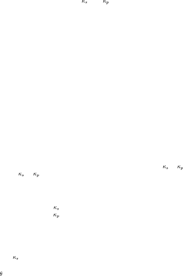
*KAPPA
11.1 *KAPPA: Specify the material parameters and for mass diffusion driven by
gradients of temperature and equivalent pressure stress, respectively.
This option is used to introduce temperature- and pressure-driven mass diffusion. It must appear immediately
after the *DIFFUSIVITY option. For each use of the *DIFFUSIVITY option, *KAPPA can be used once with
TYPE=TEMP and once with TYPE=PRESS. The *KAPPA, TYPE=TEMP and *DIFFUSIVITY, LAW=FICK
options are mutually exclusive.
Product: ABAQUS/Standard
Type: Model data
Level: Model
References:
•“Diffusivity,” Section 20.5.1 of the ABAQUS Analysis User’s Manual
•*DIFFUSIVITY
Optional parameters:
DEPENDENCIES
Set this parameter equal to the number of field variables included in the definition of or .If
this parameter is omitted, or is assumed not to depend on any field variables but may still
depend on concentration and temperature. See “Specifying field variable dependence” in “Material
data definition,” Section 16.1.2 of the ABAQUS Analysis User’s Manual, for more information.
TYPE
Set TYPE=TEMP (default) to define (governing mass diffusion caused by temperature
gradients). Set TYPE=PRESS to define (governing mass diffusion caused by gradients of the
equivalent pressure stress).
Data lines to define the Soret effect factor, ks(TYPE=TEMP):
First line:
1. Soret effect factor, .(UnitsofF
1/2 L−1 .)
2. Concentration, c.
3. Temperature, .
4. First field variable.
5. Second field variable.
6. Etc.,uptofivefieldvariables.
11.1–1
ABAQUS Version 6.1 Module: ID:
Printed on:
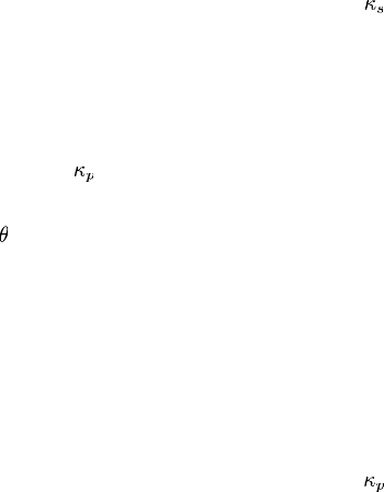
*KAPPA
Subsequent lines (only needed if the DEPENDENCIES parameter has a value greater than five):
1. Sixth field variable.
2. Etc., up to eight field variables per line.
Repeat this set of data lines as often as necessary to define as a function of concentration,
temperature, and other predefined field variables.
Data lines to define the pressure stress factor, kp(TYPE=PRESS):
First line:
1. Pressure stress factor, .(UnitsofLF
−1/2 .)
2. Concentration, c.
3. Temperature, .
4. First field variable.
5. Second field variable.
6. Etc.,uptofivefieldvariables.
Subsequent lines (only needed if the DEPENDENCIES parameter has a value greater than five):
1. Sixth field variable.
2. Etc., up to eight field variables per line.
Repeat this set of data lines as often as necessary to define as a function of concentration,
temperature, and other predefined field variables.
11.1–2
ABAQUS Version 6.1 Module: ID:
Printed on:
*KINEMATIC
11.2 *KINEMATIC: Define a kinematic coupling constraint.
This option is used to define a kinematic coupling constraint. It must be used in conjunction with the
*COUPLING option.
Products: ABAQUS/Standard ABAQUS/Explicit
Type: Model data
Level: Part, Part instance, Assembly
References:
•“Coupling constraints,” Section 28.3.2 of the ABAQUS Analysis User’s Manual
•*COUPLING
There are no parameters associated with this option.
Data lines to specify the degrees of freedom to be constrained:
First line:
1. First degree of freedom constrained. See “Conventions,” Section 1.2.2 of the
ABAQUS Analysis User’s Manual, for a definition of the numbering of degrees of freedom
in ABAQUS. If this field is left blank, all degrees of freedom will be constrained.
2. Last degree of freedom constrained. If this field is left blank, the degree of freedom specified
in the first field will be the only one constrained.
Repeat this data line as often as necessary to specify constraints for different degrees of freedom. When
the ORIENTATION parameter is specified on the associated *COUPLING option, the degrees of freedom
are in the referenced local system in the initial configuration; otherwise, they are in the global system. In
either case these directions will rotate with the reference node in large-displacement analyses (when the
NLGEOM parameter is included on the *STEP option).
11.2–1
ABAQUS Version 6.1 Module: ID:
Printed on:
*KINEMATIC COUPLING
11.3 *KINEMATIC COUPLING: Constrain all or specific degrees of freedom of a set of
nodes to the rigid body motion of a reference node.
This option is used to impose constraints between degrees of freedom of a node or node set and the rigid body
motion defined by a reference node. The preferred method of providing a kinematic constraint of this type is
the *COUPLING option used in conjunction with the *KINEMATIC option.
Product: ABAQUS/Standard
Type: Model data
Level: Part, Part instance, Assembly
Reference:
•“Kinematic constraints: overview,” Section 28.1.1 of the ABAQUS Analysis User’s Manual
Required parameter:
REF NODE
Set this parameter equal to either the node number of the reference node or the name of a node set
containing the reference node. If the name of a node set is chosen, the node set must contain exactly
one node.
Optional parameter:
ORIENTATION
Set this parameter equal to the name given to the *ORIENTATION definition (“Orientations,”
Section 2.2.5 of the ABAQUS Analysis User’s Manual) that specifies the initial orientation of the
local system in which the constrained degrees of freedom are defined.
Data lines to specify the nodes and degrees of freedom to be constrained:
First line:
1. Node number or node set label.
2. First degree of freedom constrained. See “Conventions,” Section 1.2.2 of the
ABAQUS Analysis User’s Manual, for a definition of the numbering of degrees of freedom
in ABAQUS/Standard. If this field is left blank, all degrees of freedom will be constrained.
11.3–1
ABAQUS Version 6.1 Module: ID:
Printed on:
*KINEMATIC COUPLING
3. Last degree of freedom constrained. If this field is left blank, the degree of freedom specified
in the second field will be the only one constrained.
Repeat this data line as often as necessary to specify constraints at different nodes and degrees of
freedom. When the ORIENTATION parameter is specified, the degrees of freedom are in the referenced
local system in the initial configuration; otherwise, they are in the global system. In either case these
directions will rotate with the reference node in large-displacement analyses (when the NLGEOM
parameter is included on the *STEP option).
11.3–2
ABAQUS Version 6.1 Module: ID:
Printed on:
L
12. L
ABAQUS Version 6.1 Module: ID:
Printed on:
*LATENT HEAT
12.1 *LATENT HEAT: Specify latent heats.
This option is used to specify a material’s latent heat.
Products: ABAQUS/Standard ABAQUS/Explicit
Type: Model data
Level: Model
Reference:
•“Latent heat,” Section 20.2.4 of the ABAQUS Analysis User’s Manual
There are no parameters associated with this option.
Data lines to define a material’s latent heat:
First line:
1. Latent heat per unit mass. (Units of JM−1 .)
2. Solidus temperature.
3. Liquidus temperature.
Repeat this data line as often as necessary to define phase changes in the material; one line per phase
change. Latent heat values must be given in ascending order of temperature.
12.1–1
ABAQUS Version 6.1 Module: ID:
Printed on:
*LOAD CASE
12.2 *LOAD CASE: Begin a load case definition for multiple load case analysis.
This option is used to begin each load case definition.
Product: ABAQUS/Standard
Type: History data
Level: Step
References:
•“Multiple load case analysis,” Section 6.1.3 of the ABAQUS Analysis User’s Manual
•*END LOAD CASE
Required parameter:
NAME
Set this parameter equal to a label that will be used to refer to the load case.
There are no data lines associated with this option.
12.2–1
ABAQUS Version 6.1 Module: ID:
Printed on:
M
13. M
ABAQUS Version 6.1 Module: ID:
Printed on:
*MAP SOLUTION
13.1 *MAP SOLUTION: Map a solution from an old mesh to a new mesh.
This option is used to transfer solution variables from an earlier analysis to a new mesh that occupies the same
space.
Product: ABAQUS/Standard
Type: Model data
Level: Model
Reference:
•“Mesh-to-mesh solution mapping,” Section 12.4.1 of the ABAQUS Analysis User’s Manual
Optional parameters:
INC
Set this parameter equal to the increment number from which the old solution will be read. If this
parameter is omitted, the last increment for which a solution is available will be read.
The STEP parameter must be specified if the INC parameter is used.
STEP
Set this parameter equal to the step number from which the old solution will be read. If this
parameter is omitted, the last step and increment for which a solution is available will be read.
UNBALANCED STRESS
Set UNBALANCED STRESS=RAMP (default) if the stress unbalance is to be resolved linearly
over the step.
Set UNBALANCED STRESS=STEP if the stress unbalance is to be resolved in the first
increment.
Data line to translate an old-model mesh:
First (and only) line:
1. Value of the translation to be applied in the X-direction.
2. Value of the translation to be applied in the Y-direction.
3. Value of the translation to be applied in the Z-direction.
Data lines to translate and/or rotate an old-model mesh:
First line:
1. Value of the translation to be applied in the X-direction.
13.1–1
ABAQUS Version 6.1 Module: ID:
Printed on:
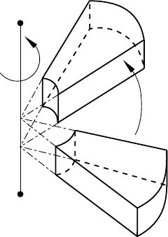
*MAP SOLUTION
2. Value of the translation to be applied in the Y-direction.
3. Value of the translation to be applied in the Z-direction.
Enter values of zero to apply a pure rotation.
Second line:
1. X-coordinate of point aon the axis of rotation (see Figure 13.1–1).
2. Y-coordinate of point aon the axis of rotation.
3. Z-coordinate of point aon the axis of rotation.
4. X-coordinate of point bon the axis of rotation.
5. Y-coordinate of point bon the axis of rotation.
6. Z-coordinate of point bon the axis of rotation.
7. Angle of rotation about the axis a–b, in degrees.
If both translation and rotation are specified, translation is applied before rotation.
θ
a
b
θ
Figure 13.1–1 Rotation of an old-model mesh.
13.1–2
ABAQUS Version 6.1 Module: ID:
Printed on:

*MASS
13.2 *MASS: Specify a point mass.
This option is used to define lumped mass values associated with MASS elements.
For ABAQUS/Standard analyses this option is also used to define mass proportional damping (for direct-
integration dynamic analysis) and composite damping (for modal dynamic analysis) associated with MASS
elements.
Products: ABAQUS/Standard ABAQUS/Explicit
Type: Model data
Level: Part, Part instance, Assembly
Reference:
•“Point masses,” Section 24.1.1 of the ABAQUS Analysis User’s Manual
Required parameter:
ELSET
Set this parameter equal to the name of the element set containing the MASS elements for which
the value is being given.
Optional parameters:
ALPHA
This parameter applies only to ABAQUS/Standard analyses.
Set this parameter equal to the factor to create mass proportional damping for the MASS
elements when used in direct-integration dynamics. This value is ignored in modal dynamics. The
default is 0.0.
COMPOSITE
This parameter applies only to ABAQUS/Standard analyses.
Set this parameter equal to the fraction of critical damping to be used with the MASS elements
when calculating composite damping factors for the modes when used in modal dynamics. This
value is ignored in direct-integration dynamics. The default is 0.0.
13.2–1
ABAQUS Version 6.1 Module: ID:
Printed on:
*MASS
Data line to define the mass magnitude:
First (and only) line:
1. Mass magnitude. Mass, not weight, should be given.
ABAQUS does not use any specific physical units, so the user’s choice must be consistent.
13.2–2
ABAQUS Version 6.1 Module: ID:
Printed on:
*MASS DIFFUSION
13.3 *MASS DIFFUSION: Transient or steady-state uncoupled mass diffusion analysis.
This option is used to control uncoupled transient or steady-state mass diffusion analysis.
Product: ABAQUS/Standard
Type: History data
Level: Step
Reference:
•“Mass diffusion analysis,” Section 6.8.1 of the ABAQUS Analysis User’s Manual
Optional parameters:
DCMAX
Set this parameter equal to the maximum normalized concentration change to be allowed in
an increment. ABAQUS/Standard will restrict the time step to ensure that this value will not
be exceeded at any node (except nodes with boundary conditions) during any increment of the
analysis. If the DCMAX parameter is omitted, fixed time increments will be used.
END
Set END=PERIOD (default) to analyze the entire time period specified on the data line. Set
END=SS to end the analysis when steady state is reached.
STEADY STATE
Include this parameter to choose steady-state analysis. Transient analysis is assumed if this
parameter is omitted.
Data line to define time stepping in a mass diffusion analysis:
First (and only) line:
1. Time step. If automatic stepping is used, this value should be a reasonable suggestion for the
initial step and will be adjusted as necessary.
2. Time period. If END=SS is chosen, the step ends when steady state is reached or after this
time period, whichever occurs first.
3. Minimum time increment allowed. If ABAQUS/Standard finds it needs a smaller time
increment than this value, the analysis is terminated. If no value is given, ABAQUS/Standard
sets the minimum increment to the minimum of 0.8 times the suggested initial time step (the
first data item on this line) and 10−5 times the time period (the second data item on this line).
13.3–1
ABAQUS Version 6.1 Module: ID:
Printed on:
*MASS DIFFUSION
If a value is given, ABAQUS/Standard will use the minimum of the given value and 0.8 times
the suggested initial time step.
4. Maximum time increment. If this value is omitted, no upper limit is imposed. This value is
used only for automatic time incrementation.
5. Rate of change of normalized concentration (normalized concentration per time) used to define
steady state; only needed if END=SS is chosen. When all nodal normalized concentrations are
changing at less than this rate, the solution terminates.
13.3–2
ABAQUS Version 6.1 Module: ID:
Printed on:
*MASS FLOW RATE
13.4 *MASS FLOW RATE: Specify fluid mass flow rate in a heat transfer analysis.
This option is used to specify the mass flow rate per unit area (or through the entire section for one-dimensional
elements) for forced convection/diffusion elements in a heat transfer analysis. This option cannot be used with
hydrostatic fluid elements.
Product: ABAQUS/Standard
Type: History data
Level: Step
References:
•“Uncoupled heat transfer analysis,” Section 6.5.2 of the ABAQUS Analysis User’s Manual
•“UMASFL,” Section 1.1.30 of the ABAQUS User Subroutines Reference Manual
Optional parameters:
AMPLITUDE
Set this parameter equal to the name of the amplitude versus time curve that defines the magnitude
of the flow rate during the step (“Amplitude curves,” Section 27.1.2 of the ABAQUS Analysis
User’s Manual). If this parameter is omitted, the reference magnitude is applied immediately at the
beginning of the step or linearly over the step, depending on the value assigned to the AMPLITUDE
parameter on the *STEP option (“Procedures: overview,” Section 6.1.1 of the ABAQUS Analysis
User’s Manual).
INPUT
Set this parameter equal to the name of the alternate input file containing the data lines for this
option. See “Input syntax rules,” Section 1.2.1 of the ABAQUS Analysis User’s Manual, for the
syntax of such file names. If this parameter is omitted, it is assumed that the data follow the keyword
line.
OP
Set OP=MOD (default) for existing *MASS FLOW RATE values to remain, with this option
modifying existing flow rates or defining additional flow rates.
Set OP=NEW if all existing *MASS FLOW RATE values applied to the model should be
removed.
USER
Include this parameter to indicate that user subroutine UMASFL will be used to define mass flow
rate values. UMASFL will be called for each node given on the data lines. If values are also given
on the data lines, these values will be ignored.
13.4–1
ABAQUS Version 6.1 Module: ID:
Printed on:
*MASS FLOW RATE
Data lines to define mass flow rates:
First line:
1. Node number or node set label.
2. Mass flow rate per unit area in the x-direction (units of ML−2 T−1 )ortotalmassflowrateinthe
cross-section (units of MT−1 ) for one-dimensional elements.
3. Mass flow rate per unit area in the y-direction (not needed for nodes associated with one-
dimensional elements).
4. Mass flow rate per unit area in the z-direction (not needed for nodes associated with one-
dimensional elements).
Repeat this data line as often as necessary to define mass flow rates at different nodes.
Data lines to define mass flow rates using user subroutine UMASFL:
First line:
1. Node set or node number.
Repeat this data line as often as necessary. UMASFL will be called for each node listed.
13.4–2
ABAQUS Version 6.1 Module: ID:
Printed on:
*MATERIAL
13.5 *MATERIAL: Begin the definition of a material.
This option is used to indicate the start of a material definition.
Products: ABAQUS/Standard ABAQUS/Explicit
Type: Model data
Level: Model
Reference:
•“Material data definition,” Section 16.1.2 of the ABAQUS Analysis User’s Manual
Required parameter:
NAME
Set this parameter equal to a label that will be used to refer to the material in the element property
options. Material names in the same input file must be unique. Furthermore, material names should
be unique from the names associated with property definitions such as *CONNECTOR BEHAVIOR
and *FLUID BEHAVIOR. Material names adhere to the naming convention for labels (see “Input
syntax rules,” Section 1.2.1 of the ABAQUS Analysis User’s Manual), except that they cannot begin
with a number.
Optional parameters:
RTOL
This parameter applies only to ABAQUS/Explicit analyses.
Set this parameter equal to the tolerance to be used for regularizing the material data. The
default is RTOL=0.03.
SRATE FACTOR
This parameter applies only to ABAQUS/Explicit analyses.
Set this parameter equal to the factor used for filtering the equivalent plastic strain rate for the
evaluation of strain rate-dependent material data. The default value is 0.9.
STRAIN RATE REGULARIZATION
This parameter applies only to ABAQUS/Explicit analyses and is used only to regularize strain
rate-dependent material data.
Set STRAIN RATE REGULARIZATION=LOGARITHMIC (default) to use a logarithmic
regularization for strain rate-dependent material data.
13.5–1
ABAQUS Version 6.1 Module: ID:
Printed on:
*MATERIAL
Set STRAIN RATE REGULARIZATION=LINEAR to use a linear regularization for strain
rate-dependent material data.
There are no data lines associated with this option.
13.5–2
ABAQUS Version 6.1 Module: ID:
Printed on:
*MATRIX
13.6 *MATRIX: Read in the stiffness or mass matrix for a linear user element.
This option can be used only in conjunction with the *USER ELEMENT, LINEAR option. It is used to read
in the stiffness or mass matrix for the user element. It can be used once if only a stiffness or mass is required
ortwicetogivebothmatrices.
Product: ABAQUS/Standard
Type: Model data
Level: Part, Part instance, Model
References:
•“User-defined elements,” Section 26.15.1 of the ABAQUS Analysis User’s Manual
•*USER ELEMENT
Required parameter:
TYPE
Set TYPE=MASS to define the mass matrix. Set TYPE=STIFFNESS to define the stiffness matrix.
Optional parameter:
INPUT
Set this parameter equal to the name of the alternate input file from which the data lines are to
be read. See “Input syntax rules,” Section 1.2.1 of the ABAQUS Analysis User’s Manual, for the
syntax of such file names. If this parameter is omitted, it is assumed that the data follow the keyword
line.
Data lines to define the matrix:
First line:
1. Matrix entries, four per line.
Repeat this data line as often as necessary.
13.6–1
ABAQUS Version 6.1 Module: ID:
Printed on:
*MATRIX ASSEMBLE
13.7 *MATRIX ASSEMBLE: Define stiffness or mass matrices for a part of the model.
This option can be used to identify a stiffness or a mass matrix that will be assembled into the corresponding
global finite element matrix. This matrix must have been input previously by using the *MATRIX INPUT
option.
Product: ABAQUS/Standard
Type: Model data
Level: Model
References:
•“Defining matrices,” Section 2.10.1 of the ABAQUS Analysis User’s Manual
•*MATRIX INPUT
At least one of the following parameters is required:
MASS
Set this parameter equal to the name of the mass matrix.
STIFFNESS
Set this parameter equal to the name of the stiffness matrix.
There are no data lines associated with this option.
13.7–1
ABAQUS Version 6.1 Module: ID:
Printed on:
*MATRIX INPUT
13.8 *MATRIX INPUT: Read in a matrix for a part of the model.
This option can be used to input a matrix in sparse format.
Product: ABAQUS/Standard
Type: Model data
Level: Model
References:
•“Defining matrices,” Section 2.10.1 of the ABAQUS Analysis User’s Manual
•*MATRIX ASSEMBLE
Required parameter:
NAME
Set this parameter equal to a label that will be used to refer to this matrix.
Optional parameters:
INPUT
Set this parameter equal to the name of the alternate input file from which the data lines are to
be read. See “Input syntax rules,” Section 1.2.1 of the ABAQUS Analysis User’s Manual, for the
syntax of such file names. If this parameter is omitted, it is assumed that the data follow the keyword
line.
SCALE FACTOR
Set this parameter equal to a nonzero real number by which all matrix entries will be multiplied.
The default value is .
Data lines to define the matrix in sparse format (only nonzero terms):
First line:
1. Row node number.
2. Degree of freedom number for row node.
3. Column node number.
13.8–1
ABAQUS Version 6.1 Module: ID:
Printed on:
*MATRIX INPUT
4. Degree of freedom number for column node.
5. Matrix entry.
Give data to define a symmetric matrix in lower triangular, upper triangular, or square format. For
a square matrix to be symmetric, corresponding entries above and below the diagonal must have
exactly the same values.
Repeat this data line as often as necessary.
13.8–2
ABAQUS Version 6.1 Module: ID:
Printed on:
*MEMBRANE SECTION
13.9 *MEMBRANE SECTION: Specify section properties for membrane elements.
This option is used to assign section properties to a set of membrane elements. Section properties include
thickness, thickness change behavior, material definition, and material orientation.
Products: ABAQUS/Standard ABAQUS/Explicit
Type: Model data
Level: Part, Part instance
Reference:
•“Membrane elements,” Section 23.1.1 of the ABAQUS Analysis User’s Manual
Required parameters:
ELSET
Set this parameter equal to the name of the element set containing the membrane elements for which
the section properties are being defined.
MATERIAL
Set this parameter equal to the name of the material to be used with these elements.
Optional parameters:
CONTROLS
In an ABAQUS/Explicit analysis, set this parameter equal to the name of a section controls
definition (see “Section controls,” Section 21.1.4 of the ABAQUS Analysis User’s Manual) to be
used to specify a nondefault hourglass control formulation option or scale factors.
In an ABAQUS/Standard analysis, set this parameter equal to the name of a section
controls definition to be used to specify the enhanced hourglass control formulation (see “Section
controls,” Section 21.1.4 of the ABAQUS Analysis User’s Manual) or to be used in a subsequent
ABAQUS/Explicit import analysis.
DENSITY
Set this parameter equal to a mass per unit surface area of the membrane.
If this parameter is used, the mass of the membrane includes a contribution from this parameter
in addition to any contribution from the material definition.
13.9–1
ABAQUS Version 6.1 Module: ID:
Printed on:
*MEMBRANE SECTION
NODAL THICKNESS
Include this parameter to indicate that the membrane thickness should not be read from the data lines
but should be interpolated from the thickness specified at the nodes with the *NODAL THICKNESS
option.
ORIENTATION
Set this parameter equal to the name given for the *ORIENTATION option to be used to define a
local coordinate system for material calculations in the elements in this set.
POISSON
This parameter is relevant only in a large-deformation analysis. Set it equal to a nonzero value
to cause the thickness to change as a function of membrane strains. The value of the POISSON
parameter must be between −1.0 and 0.5. A value of 0.5 will enforce incompressible behavior of
the element. POISSON=0.0 means that the thickness will not change.
Set this parameter equal to MATERIAL in an ABAQUS/Explicit analysis to cause the thickness
to change based on the element material definition.
The default is POISSON=0.5 in ABAQUS/Standard and POISSON=MATERIAL in
ABAQUS/Explicit.
Data line for a constant thickness membrane:
First (and only) line:
1. Section thickness.
To define a continuously varying thickness membrane:
No data lines are used with this option when the NODAL THICKNESS parameter is specified; any
value input on the data line will be ignored. Instead, the *NODAL THICKNESS option is used to
define the section thickness.
13.9–2
ABAQUS Version 6.1 Module: ID:
Printed on:
*MODAL DAMPING
13.10 *MODAL DAMPING: Specify damping for modal dynamic analysis.
This option is used to specify damping for mode-based procedures. It is usually used in conjunction with
the *SELECT EIGENMODES option for selecting eigenmodes for modal superposition. If the *SELECT
EIGENMODES option is not used, all eigenmodes extracted in the prior *FREQUENCYstepwillbeused
with the damping values specified under the *MODAL DAMPING option. If the *MODAL DAMPING
option is not used, zero damping values are assumed.
Product: ABAQUS/Standard
Type: History data
Level: Step
References:
•“Material damping,” Section 20.1.1 of the ABAQUS Analysis User’s Manual
•“Dynamic analysis procedures: overview,” Section 6.3.1 of the ABAQUS Analysis User’s Manual
Optional, mutually exclusive parameters:
MODAL
Set MODAL=DIRECT to select modal damping using the damping coefficients given in this option.
The data lines after the keyword line specify the modal damping values to be used in the analysis.
If the *MODAL DAMPING option is used without parameters, MODAL=DIRECT is assumed.
Set MODAL=COMPOSITE to select composite modal damping using the damping
coefficients that have been calculated in the *FREQUENCY step (“Natural frequency extraction,”
Section 6.3.5 of the ABAQUS Analysis User’s Manual) from the material damping factors
given on the *DAMPING material definition option (“Material damping,” Section 20.1.1 of
the ABAQUS Analysis User’s Manual). Composite modal damping can be used only with
DEFINITION=MODE NUMBERS.
RAYLEIGH
Include this parameter to select Rayleigh damping. The damping term for a particular mode is
defined as ,where and are factors defined on the first data line of the
option and is the modal mass and is the modal stiffness for mode M.
STRUCTURAL
Include this parameter to select structural damping, which means that the damping is proportional
to the internal forces but opposite in direction to the velocity. This option can be used only with the
*STEADY STATE DYNAMICS (“Mode-based steady-state dynamic analysis,” Section 6.3.8 of the
ABAQUS Analysis User’s Manual) or *RANDOM RESPONSE procedures (“Random response
13.10–1
ABAQUS Version 6.1 Module: ID:
Printed on:

*MODAL DAMPING
analysis,” Section 6.3.11 of the ABAQUS Analysis User’s Manual). The value of the damping
constant, s, that multiplies the internal forces is entered on the data line.
Optional parameter:
DEFINITION
Set DEFINITION=MODE NUMBERS (default) to indicate that the damping values are given for
thespecifiedmodenumbers.
Set DEFINITION=FREQUENCY RANGE to indicate that the damping values are given for
the specified frequency ranges. Frequency ranges can be discontinuous.
If both the *MODAL DAMPING and *SELECT EIGENMODES options are used in the same
step, the DEFINITION parameter must be set equal to the same value in both options.
Data lines to define a fraction of critical damping by specifying mode numbers (MODAL=DIRECT
and DEFINITION=MODE NUMBERS):
First line:
1. Mode number of the lowest mode of a range.
2. Mode number of the highest mode of a range. (If this entry is left blank, it is assumed to be
the same as the previous entry so that values are being given for one mode only.)
3. Fraction of critical damping, .
Repeat this data line as often as necessary to define modal damping for different modes.
Data lines to define Rayleigh damping by specifying mode numbers (RAYLEIGH and
DEFINITION=MODE NUMBERS):
First line:
1. Mode number of the lowest mode of a range.
2. Mode number of the highest mode of a range. (If this entry is left blank, it is assumed to be
the same as the previous entry so that values are being given for one mode only.)
3. Mass proportional damping, .
4. Stiffness proportional damping, .
Repeat this data line as often as necessary to define modal damping for different modes.
Data lines to define composite modal damping (MODAL=COMPOSITE):
First line:
1. Mode number of the lowest mode of a range.
2. Mode number of the highest mode of a range. (If this entry is left blank, it is assumed to be
the same as the previous entry so that values are being given for one mode only.)
Repeat this data line as often as necessary to define modal damping for different modes.
13.10–2
ABAQUS Version 6.1 Module: ID:
Printed on:
*MODAL DAMPING
Data lines to define structural damping by specifying mode numbers (STRUCTURAL and
DEFINITION=MODE NUMBERS):
First line:
1. Mode number of the lowest mode of a range.
2. Mode number of the highest mode of a range. (If this entry is left blank, it is assumed to be
the same as the previous entry so that values are being given for one mode only.)
3. Damping factor, s.
Repeat this data line as often as necessary to define modal damping for different modes.
Data lines to define a fraction of critical damping by specifying frequency ranges
(MODAL=DIRECT and DEFINITION=FREQUENCY RANGE):
First line:
1. Frequency value (in cycles/time).
2. Fraction of critical damping, .
Repeat this data line as often as necessary to define modal damping for different frequencies. ABAQUS
will interpolate linearly between frequencies and keep the damping value constant and equal to the closest
specified value outside the frequency range.
Data lines to define Rayleigh damping by specifying frequency ranges (RAYLEIGH and
DEFINITION=FREQUENCY RANGE):
First line:
1. Frequency value (in cycles/time).
2. Mass proportional damping, .
3. Stiffness proportional damping, .
Repeat this data line as often as necessary to define modal damping for different frequencies. ABAQUS
will interpolate linearly between frequencies and keep the damping value constant and equal to the closest
specified value outside the frequency range.
Data lines to define structural damping by specifying frequency ranges (STRUCTURAL and
DEFINITION=FREQUENCY RANGE):
First line:
1. Frequency value (in cycles/time).
2. Damping factor, s.
Repeat this data line as often as necessary to define modal damping for different frequencies. ABAQUS
will interpolate linearly between frequencies and keep the damping value constant and equal to the closest
specified value outside the frequency range.
13.10–3
ABAQUS Version 6.1 Module: ID:
Printed on:
*MODAL DYNAMIC
13.11 *MODAL DYNAMIC: Dynamic time history analysis using modal superposition.
This option is used to provide dynamic time history response as a linear perturbation procedure using modal
superposition.
Product: ABAQUS/Standard
Type: History data
Level: Step
Reference:
•“Transient modal dynamic analysis,” Section 6.3.7 of the ABAQUS Analysis User’s Manual
Optional parameter:
CONTINUE
Set CONTINUE=NO (default) to specify that this step is not to carry over the initial conditions
from the results of the preceding step. In this case the initial displacements are zero, and the initial
velocities are taken from the *INITIAL CONDITIONS, TYPE=VELOCITY option if it is used;
otherwise, they are zero. Step time begins at zero.
Set CONTINUE=YES to specify that this step is to carry over the initial conditions from the
end of the immediately preceding *MODAL DYNAMIC step or static perturbation step. If this
preceding step is a *MODAL DYNAMIC step, both the velocities and the displacements from
the end of this step are used as the initial conditions for the current step. If this preceding step is
a static perturbation step, the displacements from this step are used as the initial displacements
for the current step and the initial velocities are taken from the *INITIAL CONDITIONS,
TYPE=VELOCITY option if it is used; otherwise, they are zero. Step time is continued from the
immediately preceding *MODAL DYNAMIC or static perturbation step.
Data line for a transient modal dynamic analysis:
First (and only) line:
1. Time increment to be used.
2. Time period.
13.11–1
ABAQUS Version 6.1 Module: ID:
Printed on:
*MODAL FILE
13.12 *MODAL FILE: Write generalized coordinate (modal amplitude) data or eigendata to
the results file during a mode-based dynamic or eigenvalue extraction procedure.
This option is used during mode-based dynamic or eigenvalue extraction procedures to control the writing
of generalized coordinate (modal amplitude and phase) values or eigendata to the ABAQUS/Standard results
file.
Product: ABAQUS/Standard
Type: History data
Level: Step
Reference:
•“Output to the data and results files,” Section 4.1.2 of the ABAQUS Analysis User’s Manual
Optional parameter:
FREQUENCY
This parameter is valid only in mode-based dynamic procedures.
Set this parameter equal to the output frequency, in increments. The output will always be
written to the results file at the last increment of each step unless FREQUENCY=0. The default is
FREQUENCY=1. Set FREQUENCY=0 to suppress the output.
Data lines to request modal output in the results file during mode-based dynamic procedures:
First line:
1. Give the identifying keys for the variables to be written to the results file. The keys are
defined in the “Modal variables” section of “ABAQUS/Standard output variable identifiers,”
Section 4.2.1 of the ABAQUS Analysis User’s Manual.
Repeat this data line as often as necessary.
To write eigendata during an eigenvalue extraction procedure:
No data lines are required; the eigendata are written automatically.
13.12–1
ABAQUS Version 6.1 Module: ID:
Printed on:
*MODAL OUTPUT
13.13 *MODAL OUTPUT: Write generalized coordinate (modal amplitude) data to the output
database during a mode-based dynamic or complex eigenvalue extraction procedure.
This option is used during a mode-based dynamic or complex eigenvalue extraction procedure to write
generalized coordinate (modal amplitude and phase) values to the ABAQUS/Standard output database. It
must be used in conjunction with the *OUTPUT, HISTORY option.
Product: ABAQUS/Standard
Type: History data
Level: Step
References:
•“Output to the output database,” Section 4.1.3 of the ABAQUS Analysis User’s Manual
•*OUTPUT
Optional parameter:
VA R I A B L E
Set VARIABLE=ALL to indicate that all modal variables applicable to this procedure and material
type should be written to the output database.
If this parameter is omitted, the modal variables requested for output must be specified on the
data lines.
Data lines to request modal output:
First line:
1. Give the identifying keys for the variables to be written to the output database. The keys are
defined in the “Modal variables” section of “ABAQUS/Standard output variable identifiers,”
Section 4.2.1 of the ABAQUS Analysis User’s Manual.
Repeat this data line as often as necessary to define the modal variables to be written to the output
database.
13.13–1
ABAQUS Version 6.1 Module: ID:
Printed on:
*MODAL PRINT
13.14 *MODAL PRINT: Print generalized coordinate (modal amplitude) data during a mode-
based dynamic procedure.
This option is used during mode-based dynamic procedures to control the printed output of generalized
coordinate (modal amplitude and phase) values.
Product: ABAQUS/Standard
Type: History data
Level: Step
Reference:
•“Output to the data and results files,” Section 4.1.2 of the ABAQUS Analysis User’s Manual
Optional parameter:
FREQUENCY
Set this parameter equal to the output frequency, in increments. The output will always be printed
at the last increment of each step unless FREQUENCY=0. The default is FREQUENCY=1. Set
FREQUENCY=0 to suppress the output.
Data lines to request modal output in the data file:
First line:
1. Give the identifying keys for the variables to be printed. The keys are defined in the “Modal
variables” section of “ABAQUS/Standard output variable identifiers,” Section 4.2.1 of the
ABAQUS Analysis User’s Manual.
Repeat this data line as often as necessary: each line defines a table.
13.14–1
ABAQUS Version 6.1 Module: ID:
Printed on:
*MODEL CHANGE
13.15 *MODEL CHANGE: Remove or reactivate elements and contact pairs.
This option is used to remove or reactivate elements or contact pairs during an analysis.
Product: ABAQUS/Standard
Type: History data
Level: Step
References:
•“Element and contact pair removal and reactivation,” Section 11.2.1 of the ABAQUS Analysis User’s
Manual
•“Removing/reactivating ABAQUS/Standard contact pairs,” Section 29.2.6 of the ABAQUS Analysis
User’s Manual
Required, mutually exclusive parameters:
ACTIVATE
Include this parameter in any step during an analysis to indicate that elements or contact pairs may
need to be removed or added during a subsequent restart analysis.
ADD
Include this parameter to indicate that the elements or contact pairs involved are being reactivated
during the step.
Set ADD=STRAIN FREE (or include the ADD parameter without a value) to specify strain-
free reactivation for stress/displacement elements or to reactivate other elements or contact pairs.
Set ADD=WITH STRAIN to specify that stress/displacement elements are reactivated with
strain. This option is not relevant for contact pairs.
REMOVE
Include this parameter to indicate that the elements or contact pairs involved are being removed
during the step.
Optional parameter:
TYPE
This parameter can be used only with the parameters ADD or REMOVE.
Set TYPE=ELEMENT (default) to remove or reactivate elements. Set TYPE=CONTACT
PAIR to remove or reactivate contact pairs.
13.15–1
ABAQUS Version 6.1 Module: ID:
Printed on:
*MODEL CHANGE
Data lines to remove/reactivate elements (TYPE=ELEMENT):
First line:
1. Give a list of element numbers and/or element set names that are involved in the removal or
reactivation.
Repeat this data line as often as necessary.
Data lines to remove/reactivate contact pairs (TYPE=CONTACT PAIR):
First line:
1. Slave surface name used in the contact pair being removed or reactivated.
2. Master surface name used in the contact pair being removed or reactivated. For self-contact
the master surface name is omitted or is the same as the slave surface name.
Repeat this data line as often as necessary.
No data lines are used with this option when the ACTIVATE parameter is included.
13.15–2
ABAQUS Version 6.1 Module: ID:
Printed on:
*MOHR COULOMB
13.16 *MOHR COULOMB: Specify the Mohr-Coulomb plasticity model.
This option is used to define the yield surface and flow potential parameters for elastic-plastic materials
that use the Mohr-Coulomb plasticity model. It must be used in conjunction with the *MOHR COULOMB
HARDENING option.
Product: ABAQUS/Standard
Type: Model data
Level: Model
References:
•“Mohr-Coulomb plasticity,” Section 18.3.3 of the ABAQUS Analysis User’s Manual
•*MOHR COULOMB HARDENING
Optional parameters:
DEPENDENCIES
Set this parameter equal to the number of field variable dependencies included in the definition
of the material parameters other than temperature. If this parameter is omitted, it is assumed that
the material properties are constant or depend only on temperature. See “Specifying field variable
dependence” in “Material data definition,” Section 16.1.2 of the ABAQUS Analysis User’s Manual,
for more information.
DEVIATORIC ECCENTRICITY
Set this parameter equal to the flow potential eccentricity in the deviatoric plane, e. This feature
allows the shape of flow potential in the deviatoric stress space to be controlled independently of
the angle of friction. If this parameter is omitted, the deviatoric eccentricity is calculated by default
as ,where is the Mohr-Coulomb angle of friction defined on the data
lines. The range of values ecan have is .
ECCENTRICITY
Set this parameter equal to the flow potential eccentricity in the meridional plane, . The meridional
eccentricity is a small positive number that defines the rate at which the flow potential approaches
its asymptote. The default is .
Data lines to define a Mohr-Coulomb plasticity model:
First line:
1. Friction angle, ,athighconfiningpressureinthep–plane. Give the value in degrees.
13.16–1
ABAQUS Version 6.1 Module: ID:
Printed on:

*MOHR COULOMB
2. Dilation angle, , at high confining pressure in the p–plane. Give the value in degrees.
3. Temperature.
4. First field variable.
5. Second field variable.
6. Etc.,uptofivefieldvariables.
Subsequent lines (only needed if the DEPENDENCIES parameter has a value greater than five):
1. Sixth field variable.
2. Etc., up to eight field variables per line.
Repeat this set of data lines as often as necessary to define the dependence of the material parameters
on temperature and other predefined field variables.
13.16–2
ABAQUS Version 6.1 Module: ID:
Printed on:
*MOHR COULOMB HARDENING
13.17 *MOHR COULOMB HARDENING: Specify hardening for the Mohr-Coulomb plasticity
model.
This option is used to define piecewise linear hardening/softening behavior for a material defined by the Mohr-
Coulomb plasticity model. It must be used in conjunction with the *MOHR COULOMB option.
Product: ABAQUS/Standard
Type: Model data
Level: Model
References:
•“Mohr-Coulomb plasticity,” Section 18.3.3 of the ABAQUS Analysis User’s Manual
•*MOHR COULOMB
Optional parameter:
DEPENDENCIES
Set this parameter equal to the number of field variable dependencies included in the definition of
the cohesion yield stress, in addition to temperature. If this parameter is omitted, it is assumed
that the cohesion yield stress depends only on the plastic strain and, possibly, on temperature.
See “Specifying field variable dependence” in “Material data definition,” Section 16.1.2 of the
ABAQUS Analysis User’s Manual, for more information.
Data lines to define Mohr-Coulomb hardening:
First line:
1. Cohesion yield stress.
2. Absolute value of the corresponding plastic strain. (The first tabular value entered must always
be zero.)
3. Temperature.
4. First field variable.
5. Second field variable.
6. Etc.,uptofivefieldvariables.
Subsequent lines (only needed if the DEPENDENCIES parameter has a value greater than five):
1. Sixth field variable.
13.17–1
ABAQUS Version 6.1 Module: ID:
Printed on:
*MOHR COULOMB HARDENING
2. Etc., up to eight field variables per line.
Repeat this set of data lines as often as necessary to define the dependence of the cohesion yield stress
on plastic strain and, if needed, on temperature and other predefined field variables.
13.17–2
ABAQUS Version 6.1 Module: ID:
Printed on:
*MOISTURE SWELLING
13.18 *MOISTURE SWELLING: Define moisture-driven swelling.
This option is used to define the moisture-driven swelling of the solid skeleton in a partially saturated porous
medium. It can be used in the analysis of coupled wetting liquid flow and porous medium stress.
Product: ABAQUS/Standard
Type: Model data
Level: Model
Reference:
•“Moisture swelling,” Section 20.7.6 of the ABAQUS Analysis User’s Manual
There are no parameters associated with this option.
Data lines to define moisture-driven swelling:
First line:
1. Volumetric moisture swelling strain, .
2. Saturation, s. This value must lie in the range .
Repeat this data line as often as necessary to define the –srelationship from to in
increasing values of s.
13.18–1
ABAQUS Version 6.1 Module: ID:
Printed on:
*MOLECULAR WEIGHT
13.19 *MOLECULAR WEIGHT: Define the molecular weight of an ideal gas species.
This option is used to define the molecular weight of an ideal gas species. It can be used only in conjunction
with the *FLUID BEHAVIOR option.
Product: ABAQUS/Explicit
Type: Model data
Level: Part, Part instance
References:
•“Defining fluid cavities,” Section 11.6.2 of the ABAQUS Analysis User’s Manual
•“Defining inflators,” Section 11.6.4 of the ABAQUS Analysis User’s Manual
•*FLUID BEHAVIOR
•*FLUID CAVITY
There are no parameters associated with this option.
Data line to define the molecular weight:
First (and only) line:
1. Molecular weight of the ideal gas species.
13.19–1
ABAQUS Version 6.1 Module: ID:
Printed on:
*MONITOR
13.20 *MONITOR: Define a degree of freedom to monitor.
This option is used to choose a node and degree of freedom to monitor the progress of the solution in the
status file. In ABAQUS/Standard the information will also be written to the message file.
Products: ABAQUS/Standard ABAQUS/Explicit
Type: History data
Level: Step
Reference:
•“Output,” Section 4.1.1 of the ABAQUS Analysis User’s Manual
Required parameters:
DOF
Set this parameter equal to the degree of freedom to be monitored at the node. In an
ABAQUS/Explicit analysis the degree of freedom will be in the global coordinate system. If
the *TRANSFORM option is used at the node in an ABAQUS/Standard analysis, the degree of
freedom is in the local, transformed, system.
NODE
Set this parameter equal to either the node number to be monitored or the name of a node set
containing the node to be monitored. If the name of a node set is chosen, the node set must contain
exactly one node.
Optional parameter:
FREQUENCY
This parameter applies only to ABAQUS/Standard analyses.
This parameter will only affect output to the message file. Set this parameter equal to the output
frequency in increments. The output will always be printed at the last increment of each step unless
FREQUENCY=0. The default is FREQUENCY=1. Set FREQUENCY=0 to suppress the output.
There are no data lines associated with this option.
13.20–1
ABAQUS Version 6.1 Module: ID:
Printed on:
*MOTION
13.21 *MOTION: Specify motions as a predefined field.
This option is used to specify motions of node sets or individual nodes during cavity radiation heat transfer
analysis, to define the motion of a reference frame in steady-state transport analysis, or to define the velocity
of the material transported through the mesh during a static analysis.
Product: ABAQUS/Standard
Type: History data
Level: Step
References:
•“Cavity radiation,” Section 32.1.1 of the ABAQUS Analysis User’s Manual
•“Steady-state transport analysis,” Section 6.4.1 of the ABAQUS Analysis User’s Manual
•“Static stress analysis,” Section 6.2.2 of the ABAQUS Analysis User’s Manual
•“UMOTION,” Section 1.1.34 of the ABAQUS User Subroutines Reference Manual
Required, mutually exclusive parameters:
ROTATION
Include this parameter to define a rigid body rotation about an axis.
TRANSLATION
Include this parameter to give the x-, y-, and z-components of translation in the global coordinate
system or in the local coordinate system if *TRANSFORM was used at these nodes. Translational
motion is the default.
USER
Include this parameter to indicate that magnitudes of motion will be defined in user subroutine
UMOTION. If this parameter is used, any magnitudes defined by the data lines can be redefined in
the user subroutine. The value of the TYPE parameter is not relevant when this parameter is used.
This parameter cannot be used for steady-state transport analysis.
Optional parameters:
AMPLITUDE
Set this parameter equal to the name of the amplitude curve (defined in the *AMPLITUDE option)
that gives the time variation of the motion throughout the step (“Amplitude curves,” Section 27.1.2
of the ABAQUS Analysis User’s Manual).
If this parameter is omitted and the translational or rotational motion is given with
TYPE=DISPLACEMENT, the default is a RAMP function. If the translational or rotational motion
13.21–1
ABAQUS Version 6.1 Module: ID:
Printed on:
*MOTION
is given with TYPE=VELOCITY, the default is a STEP function for cavity radiation analysis and
a RAMP function for steady-state transport analysis.
TYPE
This parameter is used to specify whether the magnitude is in the form of a displacement or a
velocity.
Set TYPE=DISPLACEMENT (default for cavity radiation analysis) to give translational or
rotational displacement values.
Set TYPE=VELOCITY (only type available for steady-state transport and static analysis)
to give translational or rotational velocities. Velocity histories for cavity radiation problems can
be specified as illustrated in the discussion on prescribing large rotations in “Cavity radiation,”
Section 32.1.1 of the ABAQUS Analysis User’s Manual.
Data lines to define translational motion (TRANSLATION):
First line:
1. Node set label or node number.
2. First translational component of motion prescribed (only degrees of freedom 1, 2, or 3 can be
entered). See “Conventions,” Section 1.2.2 of the ABAQUS Analysis User’s Manual, for a
definition of the numbering of degrees of freedom in ABAQUS.
3. Last translational component of motion prescribed (only degrees of freedom 1, 2, or 3 can be
entered). This field can be left blank if motion for only one component is being prescribed.
4. Magnitude of the translational displacement or velocity. This magnitude will be modified by
the *AMPLITUDE specification if the AMPLITUDE parameter is used.
Repeat this data line as often as necessary to define translational motion for different nodes and degrees
of freedom.
Data lines to define rotational motion (ROTATION):
First line:
1. Node set label or node number.
2. Magnitude of the rotation (in radians) or rotational velocity (in radians/time). This magnitude
will be modified by the *AMPLITUDE specification if the AMPLITUDE parameter is used.
The rotation is about the axis defined from point ato point b, where the coordinates of aand
bare given next. In steady-state transport analysis the position and orientation of the rotation
axis are applied at the beginning of the step and remain fixed during the step.
3. Global x-component of point aon the axis of rotation.
4. Global y-component of point aon the axis of rotation.
13.21–2
ABAQUS Version 6.1 Module: ID:
Printed on:
*MOTION
The following data are required only for three-dimensional cases:
5. Global z-component of point aon the axis of rotation.
6. Global x-component of point bon the axis of rotation.
7. Global y-component of point bon the axis of rotation.
8. Global z-component of point bon the axis of rotation.
Repeat this data line as often as necessary to define rotational motion for different nodes.
Data lines to define motion in user subroutine UMOTION (USER):
First line:
1. Node set label or node number.
2. First translational component of motion prescribed (only degrees of freedom 1, 2, or 3 can be
entered). See “Conventions,” Section 1.2.2 of the ABAQUS Analysis User’s Manual, for a
definition of the numbering of degrees of freedom in ABAQUS.
3. Last translational component of motion prescribed (only degrees of freedom 1, 2, or 3 can be
entered). This field can be left blank if motion for only one component is being prescribed.
4. Magnitude of the translational displacement or rotation. This magnitude can be redefined in
user subroutine UMOTION.
Repeat this data line as often as necessary to define the nodes and degrees of freedom that will have
their motion prescribed by user subroutine UMOTION.
13.21–3
ABAQUS Version 6.1 Module: ID:
Printed on:
*MPC
13.22 *MPC: Define multi-point constraints.
This option is used to impose constraints between different degrees of freedom of the model.
Products: ABAQUS/Standard ABAQUS/Explicit
Type: Model data
Level: Part, Part instance, Assembly
References:
•“General multi-point constraints,” Section 28.2.2 of the ABAQUS Analysis User’s Manual
•“MPC,” Section 1.1.13 of the ABAQUS User Subroutines Reference Manual
Optional parameters:
INPUT
Set this parameter equal to the name of the alternate input file containing the data lines for this
option. See “Input syntax rules,” Section 1.2.1 of the ABAQUS Analysis User’s Manual, for the
syntax of such file names. If this parameter is omitted, it is assumed that the data follow the keyword
line.
MODE
This parameter applies only to ABAQUS/Standard analyses.
This parameter is used only if the USER parameter is included.
Set MODE=DOF (default) for user subroutine MPC to operate in a degree of freedom mode.
Set MODE=NODE for user subroutine MPC to operate in a nodal mode.
USER
This parameter applies only to ABAQUS/Standard analyses.
Include this parameter to indicate that the constraint is defined in user subroutine MPC.
Data lines to define multi-point constraints:
First line:
1. MPC type from “General multi-point constraints,” Section 28.2.2 of the ABAQUS Analysis
User’s Manual, or, if the USER parameter is included, an integer key to be used in user
subroutine MPC to distinguish between different constraint types.
2. Node numbers or node sets involved in the constraint.
The first 15 nodes or node sets of an MPC must be entered on the first line. If the MPC contains more
than 15 nodes, enter 0 on the next line to indicate that it is a continuation line and then continue to enter
13.22–1
ABAQUS Version 6.1 Module: ID:
Printed on:
*MPC
the following nodes on this line. Any number of continuation lines are allowed. Exactly 15 nodes or node
sets must be given on each line except the last line.
13.22–2
ABAQUS Version 6.1 Module: ID:
Printed on:

*MULLINS EFFECT
13.23 *MULLINS EFFECT: Specify Mullins effect material parameters for elastomers.
This option is used to define material constants for the Mullins effect in filled rubber elastomers or for
modeling energy dissipation in elastomeric foams. It can be used only with the *HYPERELASTIC or the
*HYPERFOAM options.
Products: ABAQUS/Standard ABAQUS/Explicit
Type: Model data
Level: Model
References:
•“Hyperelastic behavior of rubberlike materials,” Section 17.5.1 of the ABAQUS Analysis User’s Manual
•“Hyperelastic behavior in elastomeric foams,” Section 17.5.2 of the ABAQUS Analysis User’s Manual
•“Mullins effect in rubberlike materials,” Section 17.6.1 of the ABAQUS Analysis User’s Manual
•“Energy dissipation in elastomeric foams,” Section 17.6.2 of the ABAQUS Analysis User’s Manual
•“UMULLINS,” Section 1.1.35 of the ABAQUS User Subroutines Reference Manual
•*BIAXIAL TEST DATA
•*PLANAR TEST DATA
•*UNIAXIAL TEST DATA
Optional, mutually exclusive parameters:
TEST DATA INPUT
Include this parameter if the material constants are to be computed by ABAQUS from data taken
from simple tests on a material specimen. If this parameter is omitted in ABAQUS/Standard, the
material constants may be given directly on the data lines or the damage variable may be defined
through user subroutine UMULLINS. If this parameter is omitted in ABAQUS/Explicit, the material
constants must be given directly on the data lines.
USER
This parameter applies only to ABAQUS/Standard analyses.
Include this parameter if the damage variable defining the Mullins effect is defined in user
subroutine UMULLINS.
Optional parameters:
BETA
This parameter can be used only when the TEST DATA INPUT parameter is used; it defines the
value of while the other coefficients of the Mullins effect model are fitted from the test data. It
13.23–1
ABAQUS Version 6.1 Module: ID:
Printed on:
*MULLINS EFFECT
cannot be specified if both the R and M parameters are also specified (use the data line instead to
specify all three parameters). If this parameter is omitted, will be determined from a nonlinear,
least-squares fit of the test data. Allowable values of BETA are . The M and BETA parameters
cannot both be zero.
DEPENDENCIES
Set this parameter equal to the number of field variables, in addition to temperature, on which the
material parameters depend. If this parameter is omitted, it is assumed that the material parameters
are constant or depend only on temperature. See “Specifying field variable dependence” in
“Material data definition,” Section 16.1.2 of the ABAQUS Analysis User’s Manual, for more
information.
This parameter is not relevant if the USER or the TEST DATA INPUT parameter is included.
M
This parameter can be used only when the TEST DATA INPUT parameter is used; it defines the
value of while the other coefficients of the Mullins effect model are fitted from the test data. It
cannot be specified if both the R and BETA parameters are also specified (use the data line instead
to specify all three parameters). If this parameter is omitted, will be determined from a nonlinear,
least-squares fit of the test data. Allowable values of M are . The M and BETA parameters
cannot both be zero.
PROPERTIES
This parameter applies only to ABAQUS/Standard analyses.
This parameter can be used only if the USER parameter is specified. Set this parameter equal
to the number of property values needed as data in user subroutine UMULLINS. The default value
is 0.
R
This parameter can be used only when the TEST DATA INPUT parameter is used; it defines the
value of while the other coefficients of the Mullins effect model are fitted from the test data. It
cannot be specified if both the M and BETA parameters are also specified (use the data line instead
to specify all three parameters). If this parameter is omitted, will be determined from a nonlinear,
least-squares fit of the test data. Allowable values of R are .
To define the material behavior by giving test data:
No data lines are used with this option when the TEST DATA INPUT parameter is specified.
The data are given instead under the *BIAXIAL TEST DATA, *PLANAR TEST DATA, and
*UNIAXIAL TEST DATA options. These options are applicable except for the case where the
damage variable is defined by the user.
13.23–2
ABAQUS Version 6.1 Module: ID:
Printed on:

*MULLINS EFFECT
Data lines to define the material constants if both the TEST DATA INPUT and USER parameters
are omitted:
First line:
1. .
2. .
3. (If this entry is left blank, the default value is taken to be 0.0 in ABAQUS/Standard and 0.1
in ABAQUS/Explicit.)
4. Temperature.
5. First field variable.
6. Etc., up to four field variables.
Subsequent lines (only needed if the DEPENDENCIES parameter has a value greater than four):
1. Fifth field variable.
2. Etc., up to eight field variables per line.
Repeat this set of data lines as often as necessary to define the material constants as a function of
temperature and other predefined field variables.
Data lines to define the material properties if the USER parameter is specified:
No data lines are needed if the PROPERTIES parameter is omitted or set to 0. Otherwise, first line:
1. Material properties, eight per line.
Repeat this data line as often as necessary to define the material properties.
13.23–3
ABAQUS Version 6.1 Module: ID:
Printed on:
*M1
13.24 *M1: Define the first bending moment behavior of beams.
This option is used to define the first bending moment behavior of beams. It can be used only in conjunction
with the *BEAM GENERAL SECTION, SECTION=NONLINEAR GENERAL option.
Products: ABAQUS/Standard ABAQUS/Explicit
Type: Model data
Level: Part, Part instance
References:
•“Using a general beam section to define the section behavior,” Section 23.3.7 of the ABAQUS Analysis
User’s Manual
•*BEAM GENERAL SECTION
Optional parameters (if neither ELASTIC nor LINEAR is included, elastic-plastic response is
assumed):
DEPENDENCIES
Set this parameter equal to the number of field variable dependencies included in the moment-
curvature relationship, in addition to temperature. If this parameter is omitted, it is assumed that
the moment–curvature relationship is constant or depends only on temperature. See “Specifying
field variable dependence” in “Material data definition,” Section 16.1.2 of the ABAQUS Analysis
User’s Manual, for more information.
ELASTIC
Include this parameter if the bending moment–curvature relationship is nonlinear but elastic.
LINEAR
Include this parameter if the bending moment varies linearly with curvature.
Data lines if the LINEAR parameter is included:
First line:
1. Bending stiffness of the section about the first beam section local axis.
2. Temperature.
3. First field variable.
4. Second field variable.
5. Etc., up to six field variables.
13.24–1
ABAQUS Version 6.1 Module: ID:
Printed on:
*M1
Subsequent lines (only needed if the DEPENDENCIES parameter has a value greater than six):
1. Seventh field variable.
2. Etc., up to eight field variables per line.
Repeat this set of data lines as often as necessary to define the bending stiffness as a function of
temperature and other predefined field variables.
Data lines if the LINEAR parameter is omitted:
First line:
1. Bending moment.
2. Curvature.
3. Temperature.
4. First field variable.
5. Second field variable.
6. Etc.,uptofivefieldvariables.
Subsequent lines (only needed if the DEPENDENCIES parameter has a value greater than five):
1. Sixth field variable.
2. Etc., up to eight field variables per line.
Repeat this set of data lines as often as necessary to define the bending moment–curvature relationship
as a function of temperature and other predefined field variables.
13.24–2
ABAQUS Version 6.1 Module: ID:
Printed on:
*M2
13.25 *M2: Define the second bending moment behavior of beams.
This option is used to define the second bending moment behavior of beams. It can be used only in conjunction
with the *BEAM GENERAL SECTION, SECTION=NONLINEAR GENERAL option and is needed only
for beams in space.
Products: ABAQUS/Standard ABAQUS/Explicit
Type: Model data
Level: Part, Part instance
References:
•“Using a general beam section to define the section behavior,” Section 23.3.7 of the ABAQUS Analysis
User’s Manual
•*BEAM GENERAL SECTION
Optional parameters (if neither ELASTIC nor LINEAR is included, elastic-plastic response is
assumed):
DEPENDENCIES
Set this parameter equal to the number of field variable dependencies included in the
moment–curvature relationship, in addition to temperature. If this parameter is omitted, it is
assumed that the moment–curvature relationship is constant or depends only on temperature.
See “Specifying field variable dependence” in “Material data definition,” Section 16.1.2 of the
ABAQUS Analysis User’s Manual, for more information.
ELASTIC
Include this parameter if the bending moment–curvature relationship is nonlinear but elastic.
LINEAR
Include this parameter if the bending moment varies linearly with curvature.
Data lines if the LINEAR parameter is included:
First line:
1. Bending stiffness of the section about the second beam section local axis.
2. Temperature.
3. First field variable.
4. Second field variable.
5. Etc., up to six field variables.
13.25–1
ABAQUS Version 6.1 Module: ID:
Printed on:
*M2
Subsequent lines (only needed if the DEPENDENCIES parameter has a value greater than six):
1. Seventh field variable.
2. Etc., up to eight field variables per line.
Repeat this set of data lines as often as necessary to define the bending stiffness as a function of
temperature and other predefined field variables.
Data lines if the LINEAR parameter is omitted:
First line:
1. Bending moment.
2. Curvature.
3. Temperature.
4. First field variable.
5. Second field variable.
6. Etc.,uptofivefieldvariables.
Subsequent lines (only needed if the DEPENDENCIES parameter has a value greater than five):
1. Sixth field variable.
2. Etc., up to eight field variables per line.
Repeat this set of data lines as often as necessary to define the moment–curvature relationship as a
function of temperature and other predefined field variables.
13.25–2
ABAQUS Version 6.1 Module: ID:
Printed on:
N
14. N
ABAQUS Version 6.1 Module: ID:
Printed on:
*NCOPY
14.1 *NCOPY: Create nodes by copying.
This option is used to copy a node set to create a new node set.
Products: ABAQUS/Standard ABAQUS/Explicit
Type: Model data
Level: Part, Part instance
Reference:
•“Node definition,” Section 2.1.1 of the ABAQUS Analysis User’s Manual
Required parameters:
CHANGE NUMBER
Set this parameter equal to an integer that will be added to each of the existing node numbers to
define the node numbers of the nodes being created.
OLD SET
Set this parameter equal to the name of the node set being copied. This set will be used for the copy
operation with the nodes that belong to it at the time this *NCOPY option appears in the input file.
Required, mutually exclusive parameters:
POLE
Include this parameter if the new nodes are created by projecting the nodes in the old set from
the pole node. Each new node will be located such that the corresponding old node is equidistant
between the pole node and the new node.
This parameter is particularly useful for creating nodes associated with infinite elements
(“Infinite elements,” Section 22.2.1 of the ABAQUS Analysis User’s Manual).
REFLECT
Set REFLECT=LINE to create the new nodes by reflection through a line.
Set REFLECT=MIRROR to create the new nodes by reflection through a plane.
Set REFLECT=POINT to create the new nodes by reflection through a point.
SHIFT
Include this parameter if the new nodes are to be created by translation and/or rotation of the nodes
in the old node set. If both translation and rotation are specified, the translation is applied once
before the rotation.
14.1–1
ABAQUS Version 6.1 Module: ID:
Printed on:
*NCOPY
Optional parameters:
MULTIPLE
This parameter is used with the SHIFT parameter to define the number of times the rotation should
be applied. The default is MULTIPLE=1.
NEW SET
Set this parameter equal to the name of the node set to which the nodes created by the operation
will be assigned. This new node set will be unsorted if the OLD SET was unsorted and if the NEW
SET does not already exist. Otherwise, this new node set will be a sorted set.
If this parameter is omitted, the newly created nodes are not assigned to a node set.
Data lines if the SHIFT parameter is included:
First line:
1. Value of the translation to be applied in the X-direction.
2. Value of the translation to be applied in the Y-direction.
3. Value of the translation to be applied in the Z-direction.
Second line:
1. X-coordinate of the first point defining the rotation axis (point ain Figure 14.1–1).
2. Y-coordinate of the first point defining the rotation axis.
3. Z-coordinate of the first point defining the rotation axis.
4. X-coordinate of the second point defining the rotation axis (point bin Figure 14.1–1).
5. Y-coordinate of the second point defining the rotation axis.
6. Z-coordinate of the second point defining the rotation axis.
7. Angle of rotation about the axis a–b, in degrees.
Data line if REFLECT=LINE:
First (and only) line:
1. X-coordinate of the first point defining the reflection line (point ain Figure 14.1–2).
2. Y-coordinate of the first point defining the reflection line.
3. Z-coordinate of the first point defining the reflection line.
4. X-coordinate of the second point defining the reflection line (point bin Figure 14.1–2).
5. Y-coordinate of the second point defining the reflection line.
6. Z-coordinate of the second point defining the reflection line.
Data lines if REFLECT=MIRROR:
First line:
1. X-coordinate of the first point defining the reflection plane (point ain Figure 14.1–3).
14.1–2
ABAQUS Version 6.1 Module: ID:
Printed on:
*NCOPY
2. Y-coordinate of the first point defining the reflection plane.
3. Z-coordinate of the first point defining the reflection plane.
4. X-coordinate of the second point defining the reflection plane (point bin Figure 14.1–3).
5. Y-coordinate of the second point defining the reflection plane.
6. Z-coordinate of the second point defining the reflection plane.
Second line:
1. X-coordinate of the third point defining the reflection plane (point cin Figure 14.1–3).
2. Y-coordinate of the third point defining the reflection plane.
3. Z-coordinate of the third point defining the reflection plane.
Data line if REFLECT=POINT:
First (and only) line:
1. X-coordinate of the reflection point (point ain Figure 14.1–4).
2. Y-coordinate of the reflection point.
3. Z-coordinate of the reflection point.
Data line if the POLE parameter is included:
First (and only) line:
1. Number of the pole node (optional: it must have been defined already).
2. X-coordinate of the pole node (point ain Figure 14.1–5, only required if the pole node number
was not entered).
3. Y-coordinate of the pole node (only required if the pole node number was not entered).
4. Z-coordinate of the pole node (only required if the pole node number was not entered).
14.1–3
ABAQUS Version 6.1 Module: ID:
Printed on:
*NCOPY
b
a
Figure 14.1–1 *NCOPY, SHIFT option.
a, b define the line
New Set
a
bOld se
t
Figure 14.1–2 *NCOPY, REFLECT=LINE option.
14.1–4
ABAQUS Version 6.1 Module: ID:
Printed on:
*NCOPY
a, b, c define the mirror plane
New Set Old Set
a
cb
Figure 14.1–3 *NCOPY, REFLECT=MIRROR option.
New Set Old set
a is the point through which the nodes are reflected
a
Figure 14.1–4 *NCOPY, REFLECT=POINT option.
14.1–5
ABAQUS Version 6.1 Module: ID:
Printed on:
*NCOPY
L
L
p
ole
n
ode aold set new s
et
Figure 14.1–5 *NCOPY, POLE option.
14.1–6
ABAQUS Version 6.1 Module: ID:
Printed on:
*NFILL
14.2 *NFILL: Fill in nodes in a region.
This option is used to generate nodes for a region of a mesh by filling in nodes between two bounds.
Products: ABAQUS/Standard ABAQUS/Explicit
Type: Model data
Level: Part, Part instance
Reference:
•“Node definition,” Section 2.1.1 of the ABAQUS Analysis User’s Manual
Optional parameters:
BIAS
Include this parameter to bias the spacing of the nodes being generated toward one end of the line
of nodes being generated. Set this parameter equal to the ratio of adjacent distances between nodes
along each line of nodes generated, as the nodes go from the first bounding node set to the second.
If the BIAS parameter is less than one, the nodes are concentrated toward the first bounding node
set; if it is greater than one, the nodes are concentrated toward the second bounding set. The value
of the parameter must be positive.
The BIAS and SINGULAR parameters are mutually exclusive.
NSET
Set this parameter equal to the name of the node set to which the nodes created by this operation
(including the bounding nodes) will be assigned. Node sets generated by this option are always
sorted node sets.
SINGULAR
This parameter applies only to ABAQUS/Standard analyses.
Include this parameter for fracture mechanics calculations with second-order isoparametric
elements to create a “quarter point” crack-tip element and bias the remaining elements. Set
SINGULAR=1 or 2, depending on whether the first or the second bounding node set represents
the crack tip.
The BIAS and SINGULAR parameters are mutually exclusive.
TWO STEP
This parameter is meaningful only if the BIAS parameter is used. When this parameter is included,
the BIAS value is applied only at each second interval along the line; therefore, the midside nodes
of second-order elements will be at the middle of the two adjacent intervals.
14.2–1
ABAQUS Version 6.1 Module: ID:
Printed on:
*NFILL
Data lines to fill in nodes between two bounds:
First line:
1. Name of the node set defining the first bound of the region.
2. Name of the node set defining the second bound of the region.
3. Number of intervals along each line between bounding nodes.
4. Increment in node numbers from the node number at the first bound set end. The default is 1.
Repeat this data line as often as necessary, one line per region to be filled by this option.
14.2–2
ABAQUS Version 6.1 Module: ID:
Printed on:
*NGEN
14.3 *NGEN: Generate incremental nodes.
This option is used to generate nodes incrementally.
Products: ABAQUS/Standard ABAQUS/Explicit
Type: Model data
Level: Part, Part instance
Reference:
•“Node definition,” Section 2.1.1 of the ABAQUS Analysis User’s Manual
Optional parameters:
LINE
Set LINE=P to generate the nodes along a parabola. In this case the user must define an extra point,
the midpoint between the two end points.
Set LINE=C to generate the nodes along a circular arc. In this case the user must define an
extra point, the center of the circle.
If this parameter is omitted, the nodes will be generated along a straight line.
NSET
Set this parameter equal to the name of a node set to which the nodes will be assigned. The two
end nodes will also be included in the node set. Node sets created or modified with this option will
always be sorted.
SYSTEM
Set SYSTEM=RC (default) to define the extra node in a Cartesian coordinate system. Set
SYSTEM=C to define the extra node in a cylindrical coordinate system. Set SYSTEM=S to define
the extra node in a spherical coordinate system. See Figure 14.3–1.
Data lines to generate nodes incrementally:
First line:
1. Number of the first end node (it must have been previously defined).
2. Number of the second end node (it must have been previously defined).
3. Increment in the numbers between each node along the line. The default is 1.
4. Number of the third node giving the extra point (if required; it must have been previously
defined).
5. First coordinate of the extra point (if required).
14.3–1
ABAQUS Version 6.1 Module: ID:
Printed on:
*NGEN
6. Second coordinate of the extra point (if required).
7. Third coordinate of the extra point (if required).
The following entries are used only for a circular arc equal to or larger than 180°:
8. First component of a normal to the circular arc.
9. Second component of a normal to the circular arc.
10. Third component of a normal to the circular arc.
Repeat this data line as often as necessary.
(X,Y,Z)
Rectangular Cartesian
(default)
R
θ
Cylindrical
(θ and φ are given in degrees)
(R,θ,φ)
θ
φ
Spherical
Z
Y
X
YY
ZZ
X
X
(R,θ,Z)
Figure 14.3–1 Coordinate systems.
14.3–2
ABAQUS Version 6.1 Module: ID:
Printed on:
*NMAP
14.4 *NMAP: Map nodes from one coordinate system to another.
This option is used to map a set of nodes from one coordinate system to another.
Products: ABAQUS/Standard ABAQUS/Explicit
Type: Model data
Level: This option is not supported in a model defined in terms of an assembly of part instances.
Reference:
•“Node definition,” Section 2.1.1 of the ABAQUS Analysis User’s Manual
Required parameters:
NSET
Set this parameter equal to the name of the node set containing the nodes to be mapped. The nodes
that are mapped are those that belong to this set at the time this option is encountered.
TYPE
Set TYPE=RECTANGULAR to introduce a simple shift or rotation. Point ain Figure 14.4–1
defines the origin of the local rectangular coordinate system defining the map. The local -axis
is defined by the line joining points aand b. The local –plane is defined by the plane passing
through points a,b,andc.
Set TYPE=CYLINDRICAL to map from cylindrical coordinates. Point ain Figure 14.4–1
defines the origin of the local cylindrical coordinate system defining the map. The line going through
point aand point bdefines the -axis of the local cylindrical coordinate system. The local –plane
for is defined by the plane passing through points a,b,andc.
Set TYPE=DIAMOND to map from skewed Cartesian coordinates. Point ain Figure 14.4–1
defines the origin of the local diamond coordinate system defining the map. The line going through
point aand point bdefines the -axis of the local coordinate system. The line going through point
aand point cdefines the -axis of the local coordinate system. The line going through point aand
point ddefines the -axis of the local coordinate system.
Set TYPE=SPHERICAL to map from spherical coordinates. Point ain Figure 14.4–1 defines
the origin of the local spherical coordinate system defining the map. The line going through point
aand point bdefines the polar axis of the local spherical coordinate system. The plane passing
through point aand perpendicular to the polar axis defines the plane. The plane passing
through points a,b,andcdefines the local plane.
Set TYPE=TOROIDAL to map from toroidal coordinates. Point ain Figure 14.4–1 defines the
origin of the local toroidal coordinate system defining the map. The axis of the local toroidal system
lies in the plane defined by points a,b,andc.TheR-coordinate of the toroidal system is defined
14.4–1
ABAQUS Version 6.1 Module: ID:
Printed on:
*NMAP
by the distance between points aand b. The line between points aand bdefines the position.
For every value of the -coordinate is defined in a plane perpendicular to the plane defined by
the points a,b,andcand perpendicular to the axis of the toroidal system. lies in the plane
defined by the points by a,b,andc.
Set TYPE=BLENDED to map via blended quadratics in an ABAQUS/Standard analysis.
Data lines for TYPE=RECTANGULAR, CYLINDRICAL, DIAMOND, SPHERICAL, or TOROIDAL:
First line:
1. X-coordinate of point a(see Figure 14.4–1).
2. Y-coordinate of point a.
3. Z-coordinate of point a.
4. X-coordinate of point b.
5. Y-coordinate of point b.
6. Z-coordinate of point b.
Second line:
1. X-coordinate of point c.
2. Y-coordinate of point c.
3. Z-coordinate of point c.
The following fields are needed only for TYPE=DIAMOND:
4. X-coordinate of point d.
5. Y-coordinate of point d.
6. Z-coordinate of point d.
If TYPE=RECTANGULAR is specified and only point ais given, the coordinates of the nodes in
the set are simply shifted by ,,and .
Third line:
1. Scale factor to be applied to the first local coordinate before mapping. If the value entered is
zero or blank, a scale factor of 1.0 is assumed.
2. Scale factor to be applied to the second local coordinate before mapping. If the value entered
is zero or blank, a scale factor of 1.0 is assumed.
3. Scale factor to be applied to the third local coordinate before mapping. If the value entered is
zero or blank, a scale factor of 1.0 is assumed.
Data lines for TYPE=BLENDED:
First line:
1. Node number of the first control node.
2. X-coordinate of the point to which this control node is to be mapped.
14.4–2
ABAQUS Version 6.1 Module: ID:
Printed on:
*NMAP
3. Y-coordinate of the point to which this control node is to be mapped.
4. Z-coordinate of the point to which this control node is to be mapped.
Second line:
1. Node number of the second control node.
2. X-coordinate of the point to which this control node is to be mapped.
3. Y-coordinate of the point to which this control node is to be mapped.
4. Z-coordinate of the point to which this control node is to be mapped.
Continue, giving up to 20 control nodes, but giving at least the eight corner nodes. If an edge of the
blended mapping is to be mapped linearly, the corresponding mid-edge control node can be omitted from
the list. This is done by inserting a line with node number 0 only (a blank line) in place of the definition
of the control node and its mapped coordinates. The control nodes do not have to be nodes in the finite
element model—they can be nodes used just for mesh generation. ABAQUS eliminates any nodes that
are not used in the analysis model before doing the analysis.
14.4–3
ABAQUS Version 6.1 Module: ID:
Printed on:
*NMAP
(R, θ, φ)
φ
X
Y
a
b
c
^
Z
^
^
z
y
x
z
y
x
b
(θ = 0)
(φ = 0)
θ
θ
R
(R, θ, Z
)
(θ = 0)
rectangular skewed Cartesian
spherical cylindrical
z
y
x
(r, θ, φ)
φ
r
θ
R
b (φ = 0)
toroidal
a
d
c
b
Z
^
Y
^
X
^
c
a
Z
^
b
a
c
c
a
R
z
y
x
z
y
x
z
y
x
z
y
x
Z
^
Figure 14.4–1 Coordinate systems; angles are in degrees.
14.4–4
ABAQUS Version 6.1 Module: ID:
Printed on:
*NO COMPRESSION
14.5 *NO COMPRESSION: Introduce a compressive failure theory (tension only
materials).
This option is used to modify the elasticity definition so that no compressive stress is allowed. It can be used
only in conjunction with the *ELASTIC option.
Product: ABAQUS/Standard
Type: Model data
Level: Model
References:
•“No compression or no tension,” Section 17.2.2 of the ABAQUS Analysis User’s Manual
•*ELASTIC
There are no parameters or data lines associated with this option.
14.5–1
ABAQUS Version 6.1 Module: ID:
Printed on:
*NO TENSION
14.6 *NO TENSION: Introduce a tension failure theory (compression only material).
This option is used to modify the elasticity definition so that no tensile stress is allowed. It can be used only
in conjunction with the *ELASTIC option.
Product: ABAQUS/Standard
Type: Model data
Level: Model
References:
•“No compression or no tension,” Section 17.2.2 of the ABAQUS Analysis User’s Manual
•*ELASTIC
There are no parameters or data lines associated with this option.
14.6–1
ABAQUS Version 6.1 Module: ID:
Printed on:
*NODAL THICKNESS
14.7 *NODAL THICKNESS: Define shell or membrane thickness at nodes.
This option is used to define variable shell or membrane thicknesses on a nodal basis. The thickness
data defined with this option will be ignored unless the NODAL THICKNESS parameter is included on
either the *SHELL GENERAL SECTION or the *SHELL SECTION options for shell elements or on the
*MEMBRANE SECTION option for membrane elements.
Products: ABAQUS/Standard ABAQUS/Explicit
Type: Model data
Level: Part, Part instance
References:
•“Nodal thicknesses,” Section 2.1.3 of the ABAQUS Analysis User’s Manual
•“Membrane elements,” Section 23.1.1 of the ABAQUS Analysis User’s Manual
•“Using a shell section integrated during the analysis to define the section behavior,” Section 23.6.5 of
the ABAQUS Analysis User’s Manual
•“Using a general shell section to define the section behavior,” Section 23.6.6 of the ABAQUS Analysis
User’s Manual
•“Line spring elements for modeling part-through cracks in shells,” Section 26.10.1 of the
ABAQUS Analysis User’s Manual
•*MEMBRANE SECTION
•*SHELL GENERAL SECTION
•*SHELL SECTION
Optional parameters:
GENERATE
Include this parameter to interpolate the thickness between two bounding nodes or node sets. The
thickness for the bounding nodes or node sets must have been defined earlier. If the node sets do
not have the same number of nodes, the extra nodes in the longer set are ignored.
INPUT
Set this parameter equal to the name of the alternate input file containing the data lines for this
option. See “Input syntax rules,” Section 1.2.1 of the ABAQUS Analysis User’s Manual, for the
syntax of such file names. If this parameter is omitted, it is assumed that the data follow the keyword
line.
14.7–1
ABAQUS Version 6.1 Module: ID:
Printed on:
*NODAL THICKNESS
Data lines when the GENERATE parameter is omitted:
First line:
1. Node set label or node number.
2. Thickness.
Repeat this data line as often as necessary to define the variation in shell or membrane thickness.
Data lines when the GENERATE parameter is included:
First line:
1. Node number or node set label that defines the first bound for the generate operation.
2. Node number or node set label that defines the second bound for the generate operation.
3. Number of intervals between the bounding nodes or node sets.
4. Increment in node numbers from the first bounding node or node set.
Repeat this data line as often as necessary to define the variation in thickness.
14.7–2
ABAQUS Version 6.1 Module: ID:
Printed on:
*NODE
14.8 *NODE: Specify nodal coordinates.
This option is used to define a node directly by specifying its coordinates. Nodal coordinates given in this
option are in a local system if the *SYSTEM option is in effect when this option is used.
Products: ABAQUS/Standard ABAQUS/Explicit
Type: Model data
Level: Part, Part instance, Assembly
Reference:
•“Node definition,” Section 2.1.1 of the ABAQUS Analysis User’s Manual
Optional parameters:
INPUT
Set this parameter equal to the name of the alternate input file containing the data lines for this
option. See “Input syntax rules,” Section 1.2.1 of the ABAQUS Analysis User’s Manual, for the
syntax of such file names. If this parameter is omitted, it is assumed that the data follow the keyword
line.
NSET
Set this parameter equal to the name of the node set to which these nodes will be assigned. Node
sets created or modified with this option will always be sorted.
SYSTEM
Set SYSTEM=R (default) to give coordinates in a rectangular Cartesian coordinate system. Set
SYSTEM=C to give coordinates in a cylindrical system. Set SYSTEM=S to give coordinates in a
spherical system. See Figure 14.8–1.
The SYSTEM parameter is entirely local to this option. As the data lines are read, the
coordinates given are transformed to rectangular Cartesian coordinates immediately. If the
*SYSTEM option is also in effect, these are local rectangular Cartesian coordinates, which are
then immediately transformed to global Cartesian coordinates.
Data lines to define the node:
First line:
1. Node number.
2. First coordinate of the node.
3. Second coordinate of the node.
14.8–1
ABAQUS Version 6.1 Module: ID:
Printed on:
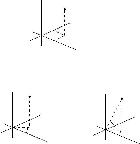
*NODE
4. Third coordinate of the node.
5. First direction cosine of the normal at the node (optional).
6. Second direction cosine of the normal at the node (optional). For nodes entered in a cylindrical
or spherical system, this entry is an angle given in degrees.
7. Third direction cosine of the normal at the node (optional). For nodes entered in a spherical
system, this entry is an angle given in degrees.
The normal will be used only for element types with rotational degrees of freedom. See Part VI,
“Elements,” of the ABAQUS Analysis User’s Manual.
Repeat this data line as often as necessary.
(X,Y,Z)
Rectangular Cartesian
(default)
R
θ
Cylindrical
(θ and φ are given in degrees)
(R,θ,φ)
θ
φ
Spherical
Z
Y
X
YY
ZZ
X
X
(R,θ,Z)
Figure 14.8–1 Coordinate systems.
14.8–2
ABAQUS Version 6.1 Module: ID:
Printed on:
*NODE FILE
14.9 *NODE FILE: Define results file requests for nodal data.
This option is used to choose the nodal variables that will be written to the results (.fil) file in an
ABAQUS/Standard analysis or to the selected results (.sel) file in an ABAQUS/Explicit analysis. In an
ABAQUS/Explicit analysis it must be used in conjunction with the *FILE OUTPUT option.
Products: ABAQUS/Standard ABAQUS/Explicit
Type: History data
Level: Step
References:
•“Output to the data and results files,” Section 4.1.2 of the ABAQUS Analysis User’s Manual
•*FILE OUTPUT
Optional parameters:
FREQUENCY
This parameter applies only to ABAQUS/Standard analyses.
Set this parameter equal to the output frequency, in increments. The output will always be
written to the results file at the last increment of each step unless FREQUENCY=0. The default is
FREQUENCY=1. Set FREQUENCY=0 to suppress the output.
GLOBAL
This parameter applies only to ABAQUS/Standard analyses.
This parameter is relevant only at nodes where the *TRANSFORM option has been used to
define a local coordinate system.
Set GLOBAL=NO to write vector-valued nodal variables in the local directions.
Set GLOBAL=YES (default) to write vector-valued nodal variables in the global directions.
This default is the opposite of the default on the *NODE PRINT option and is used because most
postprocessors assume that components are given in the global system.
LAST MODE
This parameter applies only to ABAQUS/Standard analyses.
This parameter is useful only during eigenvalue extraction for natural frequencies (“Natural
frequency extraction,” Section 6.3.5 of the ABAQUS Analysis User’s Manual) and for eigenvalue
buckling estimation (“Eigenvalue buckling prediction,” Section 6.2.3 of the ABAQUS Analysis
User’s Manual).
Set this parameter equal to the highest mode number for which output is required.
14.9–1
ABAQUS Version 6.1 Module: ID:
Printed on:
*NODE FILE
The default value is LAST MODE=N,whereNis the number of modes extracted. If the
MODE parameter is used, the default value is LAST MODE=M,whereMis the value of the MODE
parameter.
MODE
This parameter applies only to ABAQUS/Standard analyses.
This parameter is useful only during eigenvalue extraction for natural frequencies and for
eigenvalue buckling estimation. Set this parameter equal to the first mode number for which output
is required. The default is MODE=1. See also the LAST MODE parameter. When performing a
*FREQUENCY analysis, the normalization will follow the format set by the NORMALIZATION
parameter. Otherwise, the normalization is such that the largest displacement component in the
mode has a magnitude of 1.0.
NSET
Set this parameter equal to the name of the node set for which the output is being written to the
results file. If this parameter is omitted, the output will be written for all nodes in the model.
Data lines to request nodal output in the results or selected results file:
First line:
1. Give the identifying keys for the variables to be written to the results or selected results file.
The keys are defined in the “Nodal variables” section of “ABAQUS/Standard output variable
identifiers,” Section 4.2.1 of the ABAQUS Analysis User’s Manual, and “ABAQUS/Explicit
output variable identifiers,” Section 4.2.2 of the ABAQUS Analysis User’s Manual.
Repeat this data line as often as necessary to define the nodal variables to be written to the results or
selected results file.
14.9–2
ABAQUS Version 6.1 Module: ID:
Printed on:
*NODE OUTPUT
14.10 *NODE OUTPUT: Define output database requests for nodal data.
This option is used to write nodal variables to the output database. It must be used in conjunction with the
*OUTPUT option.
Products: ABAQUS/Standard ABAQUS/Explicit
Type: History data
Level: Step
References:
•“Output to the output database,” Section 4.1.3 of the ABAQUS Analysis User’s Manual
•*OUTPUT
One of the following mutually exclusive parameters is required when the *NODE OUTPUT option
is used in conjunction with the *OUTPUT, HISTORY option:
NSET
Set this parameter equal to the name of the node set for which this output request is being made.
TRACER SET
This parameter applies only to ABAQUS/Explicit analyses.
Set this parameter equal to the name of the tracer set for which this output request is being
made.
Optional parameters when the *NODE OUTPUT option is used in conjunction with the *OUTPUT,
FIELD option:
NSET
Set this parameter equal to the name of the node set for which this output request is being made.
If this parameter is omitted, the output will be written for all the nodes in the model.
TRACER SET
This parameter applies only to ABAQUS/Explicit analyses.
Set this parameter equal to the name of the tracer set for which this output request is being
made.
This parameter is valid only for displacement output requests.
14.10–1
ABAQUS Version 6.1 Module: ID:
Printed on:
*NODE OUTPUT
Optional parameter:
VA R I A B L E
Set VARIABLE=ALL to indicate that all nodal variables applicable to this procedure and material
type should be written to the output database.
Set VARIABLE=PRESELECT to indicate that the default nodal output variables for the
current procedure type should be written to the output database. Additional output variables can
be requested on the data lines.
If this parameter is omitted, the nodal variables requested for output must be specified on the
data lines.
Data lines to request nodal output:
First line:
1. Specify the identifying keys for the variables to be written to the output database. The
keys are defined in “ABAQUS/Standard output variable identifiers,” Section 4.2.1 of the
ABAQUS Analysis User’s Manual, and “ABAQUS/Explicit output variable identifiers,”
Section 4.2.2 of the ABAQUS Analysis User’s Manual.
Repeat this data line as often as necessary to define the nodal variables to be written to the output
database.
14.10–2
ABAQUS Version 6.1 Module: ID:
Printed on:
*NODE PRINT
14.11 *NODE PRINT: Define print requests for nodal variables.
This option is used to provide tabular printed output of nodal variables (displacements, reaction forces, etc.)
in the data file.
Product: ABAQUS/Standard
Type: History data
Level: Step
Reference:
•“Output to the data and results files,” Section 4.1.2 of the ABAQUS Analysis User’s Manual
Optional parameters:
FREQUENCY
Set this parameter equal to the output frequency in increments. The output will always be printed
at the last increment of each step unless FREQUENCY=0. The default is FREQUENCY=1. Set
FREQUENCY=0 to suppress the output.
GLOBAL
This parameter is relevant only at nodes where the *TRANSFORM option has been used to define
a local coordinate system.
Set GLOBAL=NO (default) to obtain printout of vector-valued nodal variables in the local
directions.
Set GLOBAL=YES to obtain printout of vector-valued nodal variables in the global directions.
LAST MODE
This parameter is useful only during eigenvalue extraction for natural frequencies (“Natural
frequency extraction,” Section 6.3.5 of the ABAQUS Analysis User’s Manual), complex
eigenvalue extraction (“Complex eigenvalue extraction,” Section 6.3.6 of the ABAQUS Analysis
User’s Manual), and eigenvalue buckling estimation (“Eigenvalue buckling prediction,”
Section 6.2.3 of the ABAQUS Analysis User’s Manual). Set this parameter equal to the highest
mode number for which output is required.
The default value is LAST MODE=N,whereNis the number of modes extracted. If the
MODE parameter is used, the default value is LAST MODE=M,whereMis the value of the MODE
parameter.
MODE
This parameter is useful only during natural frequency extraction, complex eigenvalue extraction,
and eigenvalue buckling estimation. Set this parameter equal to the first mode number for which
14.11–1
ABAQUS Version 6.1 Module: ID:
Printed on:
*NODE PRINT
output is required. The default is MODE=1. See also the LAST MODE parameter. When
performing a *FREQUENCY analysis, the normalization will follow the format set by the
NORMALIZATION parameter. Otherwise, the normalization is such that the largest displacement
component in the mode has a magnitude of 1.0.
NSET
Set this parameter equal to the name of the node set for which this output request is being made. If
this parameter is omitted, the output will be printed for all of the nodes in the model.
SUMMARY
Set SUMMARY=YES (default) to obtain a summary and the locations of the maximum and
minimum values in each column of the table. Set SUMMARY=NO to suppress this summary.
TOTALS
Set TOTALS=YES to print the total of each column in the table. This is useful, for example, to sum
reaction forces in a particular direction. The default is TOTALS=NO.
Data lines to request nodal output in the data file:
First line:
1. Give the identifying keys for the variables to be printed in a table for this node set. The keys are
defined in the “Nodal variables” portion of “ABAQUS/Standard output variable identifiers,”
Section 4.2.1 of the ABAQUS Analysis User’s Manual.
Repeat this data line as often as necessary: each line defines a table. If this line is omitted, no nodal
output will be printed to the data file.
14.11–2
ABAQUS Version 6.1 Module: ID:
Printed on:
*NODE RESPONSE
14.12 *NODE RESPONSE: Define nodal responses for design sensitivity analysis.
This option is used to write nodal response sensitivities to the output database. It must be used in conjunction
with the *DESIGN RESPONSE option.
Product: ABAQUS/Design
Type: History data
Level: Step
References:
•“Design sensitivity analysis,” Section 14.1.1 of the ABAQUS Analysis User’s Manual
•*DESIGN RESPONSE
Optional parameter:
NSET
Set this parameter equal to the name of the node set for which this sensitivity output is being made.
Data lines to request nodal sensitivity output:
First line:
1. Specify the identifying keys for the responses whose sensitivities are to be written to the output
database. The valid keys are listed in “Design sensitivity analysis,” Section 14.1.1 of the
ABAQUS Analysis User’s Manual.
Repeat this data line as often as necessary to define the nodal responses whose sensitivities are to be
written to the output database.
14.12–1
ABAQUS Version 6.1 Module: ID:
Printed on:
*NONSTRUCTURAL MASS
14.13 *NONSTRUCTURAL MASS: Specify mass contribution to the model from
nonstructural features.
This option is used to include the mass contribution from nonstructural features in the model. The
nonstructural mass can be applied over an element set that contains solid, shell, membrane, surface, beam,
or truss elements.
Products: ABAQUS/Standard ABAQUS/Explicit
Type: Model data
Level: Part, Part instance, Assembly
Reference:
•“Nonstructural mass definition,” Section 2.6.1 of the ABAQUS Analysis User’s Manual
Required parameters:
ELSET
Set this parameter equal to the name of the element set containing the elements over which a given
nonstructural mass is to be distributed.
UNITS
Set UNITS=TOTAL MASS to specify the nonstructural mass in the units of “mass.”
Set UNITS=MASS PER VOLUME to specify the nonstructural mass in the units of “mass per
unit volume.”
Set UNITS=MASS PER AREA to specify the nonstructural mass in the units of “mass per
unit area.” This value is valid only for an element set that contains conventional shells, membranes,
and/or surface elements.
Set UNITS=MASS PER LENGTH to specify the nonstructural mass in the units of “mass per
unit length.” This value is valid only for an element set that contains beam and/or truss elements.
Optional parameter:
DISTRIBUTION
This parameter is relevant only when UNITS=TOTAL MASS.
Set DISTRIBUTION=MASS PROPORTIONAL (default) to distribute the total nonstructural
mass among the members of the element set region in proportion to the element structural mass.
The underlying structural density over the element set region is scaled uniformly; therefore, the
center of mass for the element set region is not altered.
14.13–1
ABAQUS Version 6.1 Module: ID:
Printed on:
*NONSTRUCTURAL MASS
Set DISTRIBUTION=VOLUME PROPORTIONAL to distribute the total nonstructural mass
among the members of the element set region in proportion to the element volume in the initial
configuration. A uniform value is added to the underlying structural density over the element set
region; therefore, if the region has nonuniform structural density, the center of mass for the element
set region may be altered.
Data line for UNITS=TOTAL MASS:
First (and only) line:
1. Mass magnitude of the nonstructural feature for distribution over the element set region. Mass,
not weight, should be given.
ABAQUS does not use any specific physical units, so the user’s choice must be consistent.
Data line for UNITS=MASS PER VOLUME:
First (and only) line:
1. Mass per unit volume of the nonstructural feature for application over the element set region.
ABAQUS does not use any specific physical units, so the user’s choice must be consistent.
Data line for UNITS=MASS PER AREA:
First (and only) line:
1. Mass per unit area of the nonstructural feature for application over the element set region.
ABAQUS does not use any specific physical units, so the user’s choice must be consistent.
Data line for UNITS=MASS PER LENGTH:
First (and only) line:
1. Mass per unit length of the nonstructural feature for application over the element set region.
ABAQUS does not use any specific physical units, so the user’s choice must be consistent.
14.13–2
ABAQUS Version 6.1 Module: ID:
Printed on:
*NORMAL
14.14 *NORMAL: Specify a particular normal direction.
This option is used to define alternative nodal normals for elements. In an ABAQUS/Standard analysis it can
also be used to define alternative normals for contact surfaces.
Products: ABAQUS/Standard ABAQUS/Explicit
Type: Model data
Level: Part, Part instance, Assembly
Reference:
•“Normal definitions at nodes,” Section 2.1.4 of the ABAQUS Analysis User’s Manual
Optional parameter:
TYPE
Set TYPE=ELEMENT (default) to allow the alternative normal definition of elements.
Set TYPE=CONTACT SURFACE to allow the alternative normal definition of contact surfaces
in an ABAQUS/Standard analysis.
Data lines to define normals for elements (TYPE=ELEMENT):
First line:
1. Element number or element set label.
2. Node number or node set label.
3. First component of normal in global coordinates.
4. Second component of normal in global coordinates.
5. Third component of normal in global coordinates.
Repeat this data line as often as necessary to define the normals.
Data lines to define normals for contact surfaces (TYPE=CONTACT SURFACE):
First line:
1. Master surface name.
2. Node number or node set label (on master surface).
3. First component of normal in global coordinates.
4. Second component of normal in global coordinates.
5. Third component of normal in global coordinates.
Repeat this data line as often as necessary to define the normals.
14.14–1
ABAQUS Version 6.1 Module: ID:
Printed on:
*NSET
14.15 *NSET: Assign nodes to a node set.
This option assigns nodes to a node set.
Products: ABAQUS/Standard ABAQUS/Explicit
Type: Model or history data
Level: Part, Part instance, Assembly, Model, Step
Reference:
•“Node definition,” Section 2.1.1 of the ABAQUS Analysis User’s Manual
Required parameter:
NSET
Set this parameter equal to the name of the node set to which the nodes will be assigned.
Optional parameters:
ELSET
Set this parameter equal to the name of a previously defined element set. The nodes that define the
elements that belong to this element set at the time this option is encountered will be assigned to
the node set specified. The UNSORTED parameter cannot be used with this parameter.
The ELSET and GENERATE parameters are mutually exclusive.
GENERATE
If this parameter is included, each data line should give a first node, ; a last node; ;andthe
increment in node numbers between these nodes, i. Then, all nodes going from to in steps
of iwill be added to the set. imust be an integer such that is a whole number (not a
fraction).
The ELSET and GENERATE parameters are mutually exclusive.
INSTANCE
Set this parameter equal to the name of the part instance that contains the nodes listed on the data
line. This parameter can be used only at the assembly level and is intended to be used as a shortcut
to the naming convention. It can be used only in a model defined in terms of an assembly of part
instances.
14.15–1
ABAQUS Version 6.1 Module: ID:
Printed on:
*NSET
INTERNAL
ABAQUS/CAE uses the INTERNAL parameter to identify sets that are created internally. The
INTERNAL parameter is used only in models defined in terms of an assembly of part instances.
The default is to omit the INTERNAL parameter.
UNSORTED
If this parameter is included, the nodes in this node set will be assigned to the set (or added to the
set if it already exists) in the order in which they are given. This parameter will be ignored if the
ELSET parameter is used.
If this parameter is omitted, the nodes in the set are sorted into ascending order of their node
numbers, with duplicates eliminated.
Data lines if the GENERATE parameter is omitted:
First line:
1. List of nodes or node set labels to be assigned to this node set. Only previously defined node
sets can be assigned to another node set.
Repeat this data line as often as necessary. Up to 16 entries are allowed per line.
Data lines if the GENERATE parameter is included:
First line:
1. First node in the set.
2. Last node in the set.
3. Increment in node numbers between nodes in the set. The default is 1.
Repeat this data line as often as necessary.
There are no data lines when the ELSET parameter is specified.
14.15–2
ABAQUS Version 6.1 Module: ID:
Printed on:
O
15. O
ABAQUS Version 6.1 Module: ID:
Printed on:
*ORIENTATION
15.1 *ORIENTATION: Define a local axis system for material or element property
definition, for kinematic coupling constraints, for free directions for inertia relief
loads, or for connectors.
This option is used to define a local coordinate system for definition of material properties; for material
calculations at integration points; for element property definitions (e.g., connector elements); for output
of components of stress, strain, and element section forces; and for kinematic and distributing coupling
constraints. In ABAQUS/Standard it can be used to define local directions for contact pair interaction
properties and spring, dashpot, and JOINTC elements; for definition of local free directions for inertia relief
loads; and for output of components of surface variables.
Products: ABAQUS/Standard ABAQUS/Explicit
Type: Model data
Level: Part, Part instance, Assembly
References:
•“Orientations,” Section 2.2.5 of the ABAQUS Analysis User’s Manual
•“ORIENT,” Section 1.1.14 of the ABAQUS User Subroutines Reference Manual
Required parameter:
NAME
Set this parameter equal to a label that will be used to refer to the orientation definition. Orientation
names in the same input file must be unique.
Optional parameters:
DEFINITION
Set DEFINITION =COORDINATES (default) to define the local system by giving the coordinates
of the three points a,b, and, optionally, c(the origin) appropriate to the SYSTEM choice from
Figure 15.1–1.
Set DEFINITION=NODES to define the local system by giving global node numbers for points
a,b, and, optionally, c(the origin).
Set DEFINITION=OFFSET TO NODES to define the local system by giving local node
numbers (on the element where the orientation is being used) to define the points a,b,and,
optionally, c(the origin) in Figure 15.1–1. This parameter value cannot be used with spring,
dashpot, or JOINTC elements. In addition, it cannot be used with the *KINEMATIC COUPLING,
*INERTIA RELIEF, or *CONTACT PAIR options.
15.1–1
ABAQUS Version 6.1 Module: ID:
Printed on:
*ORIENTATION
SYSTEM
Set SYSTEM=RECTANGULAR (default) to define a rectangular Cartesian system by the three
points a,b,andcshown in Figure 15.1–1. Point cis the origin of the system, point amust lie on the
-axis, and point bmust lie on the -plane. Although not necessary, it is intuitive to select
point bsuch that it is on or near the local -axis.
Set SYSTEM=CYLINDRICAL to define a cylindrical system by giving the two points
aand bon the polar axis of the cylindrical system (Figure 15.1–1). The local axes are 1=radial,
2=circumferential, 3=axial.
Set SYSTEM=SPHERICAL to define a spherical system by giving the center of the sphere,
a, and point bon the polar axis (Figure 15.1–1). The local axes are 1=radial, 2=circumferential,
3=meridional.
Set SYSTEM=Z RECTANGULAR in an ABAQUS/Standard analysis to define a rectangular
Cartesian system by the three points a,b,andcshown in Figure 15.1–1. Point cis the origin of
the system, point amust lie on the -axis, and point bmust lie on the -plane. Although not
necessary, it is intuitive to select point bsuch that it is on or near the local -axis.
Set SYSTEM=USER in an ABAQUS/Standard analysis to define the local coordinate system
in user subroutine ORIENT. The DEFINITION parameter, and any data lines associated with the
option are ignored if SYSTEM=USER.
Data lines to define an orientation using DEFINITION=COORDINATES:
First line:
1. X-coordinate of point a.
2. Y-coordinate of point a.
3. Z-coordinate of point a.
4. X-coordinate of point b.
5. Y-coordinate of point b.
6. Z-coordinate of point b.
The following items, the coordinates of point c(the origin), are optional and relevant only for
SYSTEM=RECTANGULAR and SYSTEM=Z RECTANGULAR. The default location of the
origin, c, is the global origin.
7. X-coordinate of point c.
8. Y-coordinate of point c.
9. Z-coordinate of point c.
Second line (mandatory for shells, membranes, gaskets, composite solid sections, and contact pairs):
1. Local direction about which the additional rotation or rotations are given. The default is the
local 1-direction. For shell, membrane, and cohesive elements this direction should have a
nonzero component in the direction of the normal to the surface.
2. Additional rotation (in degrees) applied to both directions orthogonal to the specified local
direction. The default is zero degrees.
15.1–2
ABAQUS Version 6.1 Module: ID:
Printed on:

*ORIENTATION
Data lines to define an orientation using DEFINITION=NODES:
First line:
1. Node number of the node at point a.
2. Node number of the node at point b.
The next item, specification of point c(the origin), is optional and relevant only for
SYSTEM=RECTANGULAR and SYSTEM=Z RECTANGULAR. The default location of
the origin, c, is the global origin.
3. Node number of the node at point c.
Second line (mandatory for shells, membranes, gaskets, composite solid sections, and contact pairs):
1. Local direction about which the additional rotation or rotations are given. The default is the
local 1-direction. For shell, membrane, and cohesive elements this direction should have a
nonzero component in the direction of the normal to the surface.
2. Additional rotation (in degrees) applied to both directions orthogonal to the specified local
direction. The default is zero degrees.
Data lines to define an orientation using DEFINITION=OFFSET TO NODES:
First line:
1. Local node number of point a.
2. Local node number of point b.
The next item, specification of point c(the origin), is optional and relevant only for
SYSTEM=RECTANGULAR and SYSTEM=Z RECTANGULAR. The default location of
the origin, c, is the first node of the element (local node number 1).
3. Local node number of point c.
Second line (mandatory for shells, membranes, gaskets, and composite solid sections):
1. Local direction about which the additional rotation or rotations are given. The default is the
local 1-direction. For shell, membrane, and cohesive elements this direction should have a
nonzero component in the direction of the normal to the surface.
2. Additional rotation (in degrees) applied to both directions orthogonal to the specified local
direction. The default is zero degrees.
To define an orientation using a user subroutine (SYSTEM=USER):
No data lines are used with this option when SYSTEM=USER is specified. Instead, user subroutine
ORIENT must be used to define the orientation.
15.1–3
ABAQUS Version 6.1 Module: ID:
Printed on:
*ORIENTATION
Y
Z
S
YSTEM = CYLINDRICAL
S
YSTEM = SPHERICAL
Z (meridional)
b
a
Y (circumferentia
l)
X (radial)
X (radial)
Y (tangential)
Zb
a
X (global)
Y
Z
X (global)
S
YSTEM = Z RECTANGULAR
S
YSTEM = RECTANGULAR
a
b
c
Y
X
Z
a
b
c
Z
Y
X
Y
Z
X (global)
Y
Z
X (global)
Figure 15.1–1 Orientation systems.
15.1–4
ABAQUS Version 6.1 Module: ID:
Printed on:

*ORNL
15.2 *ORNL: Specify constitutive model developed by Oak Ridge National Laboratory.
This option is used to provide plasticity and creep calculations for type 304 and 316 stainless steel according
to the specification in Nuclear Standard NEF 9–5 T, “Guidelines and Procedures for Design of Class I
Elevated Temperature Nuclear System Components.” It can be used only with the *PLASTIC option and/or
the *CREEP, LAW=STRAIN option.
Product: ABAQUS/Standard
Type: Model data
Level: Model
Reference:
•“ORNL – Oak Ridge National Laboratory constitutive model,” Section 18.2.12 of the ABAQUS Analysis
User’s Manual
Optional parameters:
A
Set this parameter equal to the saturation rates for kinematic shift caused by creep strain, as defined
by Equation (15) of Section 4.3.3–3 of the Nuclear Standard. The default value is 0.3, as per that
section of the Standard. Set A=0.0 to use the 1986 revision of the Standard.
H
Set this parameter equal to the rate of kinematic shift with respect to creep strain [Equation (7) of
Section 4.3.2–1 of the Nuclear Standard]. Set H=0.0 to use the 1986 revision of the Standard. If
this parameter is omitted, the value of His determined according to Section 4.3.3–3 of the 1981
revision of the Standard.
MATERIAL
Set MATERIAL=SS to use the hardening law appropriate to either type 304 or type 316 stainless
steel. This is the only option presently available and, thus, the default.
RESET
Include this parameter to invoke the optional reset procedure described in Section 4.3.5 of the
Nuclear Standard. If this parameter is omitted, the reset procedure is not used.
There are no data lines associated with this option.
15.2–1
ABAQUS Version 6.1 Module: ID:
Printed on:

*OUTPUT
15.3 *OUTPUT: Define output requests to the output database.
This option is used to write contact, element, energy, nodal, or diagnostic output to the output database. In
an ABAQUS/Standard analysis it is also used to write modal or radiation output to the output database. In
an ABAQUS/Explicit analysis it is also used to write incrementation output to the output database. The
*CONTACT OUTPUT, *ELEMENT OUTPUT, *ENERGY OUTPUT, *INCREMENTATION OUTPUT,
*MODAL OUTPUT, *NODE OUTPUT, and/or *RADIATION OUTPUT options can be used in conjunction
with this option.
Products: ABAQUS/Standard ABAQUS/Explicit
Type: History data
Level: Step
Using *OUTPUT in an ABAQUS/Standard analysis
References:
•“Output to the output database,” Section 4.1.3 of the ABAQUS Analysis User’s Manual
•“ABAQUS/Standard output variable identifiers,” Section 4.2.1 of the ABAQUS Analysis User’s Manual
•“Overview of job diagnostics,” Section 23.1 of the ABAQUS/CAE User’s Manual
•*CONTACT OUTPUT
•*ELEMENT OUTPUT
•*ENERGY OUTPUT
•*MODAL OUTPUT
•*NODE OUTPUT
•*RADIATION OUTPUT
•*TIME POINTS
One of the following mutually exclusive parameters is required:
DIAGNOSTICS
Set DIAGNOSTICS=YES (default) to indicate that detailed diagnostic information should be
written to the output database. Set DIAGNOSTICS=NO to suppress the output.
FIELD
Include this parameter to indicate that the output requests used in conjunction with the *OUTPUT
option will be written to the output database as field-type output.
15.3–1
ABAQUS Version 6.1 Module: ID:
Printed on:
*OUTPUT
HISTORY
Include this parameter to indicate that the output requests used in conjunction with the *OUTPUT
option will be written to the output database as history-type output.
Optional parameters:
FREQUENCY
Set this parameter equal to the output frequency, in increments. The output will always be written to
the output database at the last increment of each step. Set FREQUENCY=0 to suppress the output.
If this parameter and the NUMBER INTERVAL, TIME INTERVAL, and TIME POINTS
parameters are omitted, output will be written at every increment of the analysis for all procedure
types except *DYNAMIC and *MODAL DYNAMIC; output will be written every 10 increments
for these procedure types.
The FREQUENCY, NUMBER INTERVAL, TIME INTERVAL, and TIME POINTS
parameters are mutually exclusive.
MODE LIST
Include this parameter to indicate that a list of eigenmodes for which output is desired will be listed
on the data lines. This parameter is valid only in a *FREQUENCY, *COMPLEX FREQUENCY,
or *BUCKLE procedure, and if the FIELD parameter is included.
NUMBER INTERVAL
Set this parameter equal to the number of intervals during the step at which the output database
states are to be written.
If this parameter and the FREQUENCY, TIME INTERVAL, and TIME POINTS parameters
are omitted, output will be written at every increment of the analysis for all procedure types except
*DYNAMIC and *MODAL DYNAMIC; output will be written every 10 increments for these
procedure types.
The FREQUENCY, NUMBER INTERVAL, TIME INTERVAL, and TIME POINTS
parameters are mutually exclusive.
TIME MARKS
Set TIME MARKS=YES (default) to write results at the exact times dictated by the NUMBER
INTERVAL, TIME INTERVAL, or TIME POINTS parameter.
Set TIME MARKS=NO to write results to the output database at the increment ending
immediately after the time dictated by the NUMBER INTERVAL, TIME INTERVAL, or TIME
POINTS parameter.
TIME POINTS
Set this parameter equal to the name of the *TIME POINTS option that defines the time points at
which output is to be written.
If this parameter and the FREQUENCY, NUMBER INTERVAL, and TIME INTERVAL
parameters are omitted, output will be written at every increment of the analysis for all procedure
15.3–2
ABAQUS Version 6.1 Module: ID:
Printed on:
*OUTPUT
types except *DYNAMIC and *MODAL DYNAMIC; output will be written every 10 increments
for these procedure types.
The FREQUENCY, NUMBER INTERVAL, TIME INTERVAL, and TIME POINTS
parameters are mutually exclusive.
The following parameters are optional and valid only if the FIELD or HISTORY parameter is
included:
OP
Set OP=NEW (default) to indicate that all output database requests defined in previous steps should
be removed. New output database requests can be defined.
Set OP=ADD to indicate that the output request being defined should be added to the output
requests defined in previous steps.
Set OP=REPLACE to indicate that this output request should replace an output request of the
same type (e.g., FIELD) and frequency defined in a previous step. If there is no matching request,
this output request will be interpreted as OP=ADD.
TIME INTERVAL
Set this parameter equal to the time interval at which the output states are to be written.
If this parameter and the FREQUENCY, NUMBER INTERVAL, and TIME POINTS
parameters are omitted, output will be written at every increment of the analysis for all procedure
types except *DYNAMIC and *MODAL DYNAMIC; output will be written every 10 increments
for these procedure types.
The FREQUENCY, NUMBER INTERVAL, TIME INTERVAL, and TIME POINTS
parameters are mutually exclusive.
VA R I A B L E
Set VARIABLE=ALL to indicate that all variables applicable to this procedure and material type
should be written to the output database.
Set VARIABLE=PRESELECT to indicate that the default output variables for the current
procedure type should be written to the output database. Additional output requests can be defined
with the output options used in conjunction with the *OUTPUT option, listed previously.
If this parameter is omitted, only the variables requested for output with the individual output
options will be written to the output database.
Data lines to list desired eigenmodes if the MODE LIST parameter is included:
First line:
1. Specify a list of desired eigenmodes.
Repeat this data line as often as necessary. Up to 16 entries are allowed per line.
15.3–3
ABAQUS Version 6.1 Module: ID:
Printed on:

*OUTPUT
Using *OUTPUT in an ABAQUS/Explicit analysis
References:
•“Output to the output database,” Section 4.1.3 of the ABAQUS Analysis User’s Manual
•“ABAQUS/Explicit output variable identifiers,” Section 4.2.2 of the ABAQUS Analysis User’s Manual
•“Overview of job diagnostics,” Section 23.1 of the ABAQUS/CAE User’s Manual
•*CONTACT OUTPUT
•*ELEMENT OUTPUT
•*ENERGY OUTPUT
•*INCREMENTATION OUTPUT
•*NODE OUTPUT
•*TIME POINTS
One of the following mutually exclusive parameters is required:
FIELD
Include this parameter to indicate that the output requests used in conjunction with the *OUTPUT
option will be written to the output database as field-type output.
HISTORY
Include this parameter to indicate that the output requests used in conjunction with the *OUTPUT
option will be written to the output database as history-type output.
The following parameters are optional and valid only if the FIELD parameter is included:
NUMBER INTERVAL
Set this parameter equal to the number of intervals during the step at which the output database
states are to be written. ABAQUS/Explicit will always write the results at the beginning of the
step. For example, if NUMBER INTERVAL=10, ABAQUS/Explicit will write 11 output database
states consisting of the values at the beginning of the step and the values at the end of 10 intervals
throughout the step. The value of this parameter must be a positive integer or zero. A value of zero
suppresses all output. If this parameter is omitted, its value will be set to 20.
The NUMBER INTERVAL and TIME POINTS parameters are mutually exclusive.
TIME MARKS
Set TIME MARKS=NO (default) to write results to the output database at the increment ending
immediately after the time dictated by the NUMBER INTERVAL or TIME POINTS parameter.
Set TIME MARKS=YES to write results at the exact times dictated by the NUMBER
INTERVAL or TIME POINTS parameter.
TIME MARKS=YES cannot be used when either the FIXED TIME INCREMENTATION or
DIRECT USER CONTROL parameter is included on the *DYNAMIC option.
15.3–4
ABAQUS Version 6.1 Module: ID:
Printed on:
*OUTPUT
TIME POINTS
Set this parameter equal to the name of the *TIME POINTS option that defines the time points
at which output is to be written. If this parameter and the NUMBER INTERVAL parameter are
omitted, field output will be written at 20 equally spaced intervals throughout the step.
The NUMBER INTERVAL and TIME POINTS parameters are mutually exclusive.
The following parameters are optional and valid only if the HISTORY parameter is included:
FILTER
Set this parameter equal to the name of the *FILTER option to be used to filter the element, nodal,
contact, fastener interaction, or integrated history output.
Set FILTER=ANTIALIASING to filter the data based on the sampling interval that is specified;
in this case the filter does not need to be defined in the model data. If FILTER=ANTIALIASING,
the TIME INTERVAL parameter is required and the FREQUENCY parameter cannot be used.
FREQUENCY
Set this parameter equal to the output frequency, in increments. The output will always be written
to the output database at the last increment of each step. Set FREQUENCY=0 to suppress the
output. If both this parameter and the TIME INTERVAL parameter are omitted, history output will
be written at 200 equally spaced intervals throughout the step.
The FREQUENCY and TIME INTERVAL parameters are mutually exclusive.
The following parameters are optional and valid only if the FIELD or HISTORY parameter is
included:
OP
Set OP=NEW (default) to indicate that all output database requests defined in previous steps should
be removed. New output database requests can be defined.
Set OP=ADD to indicate that the output request being defined should be added to the output
requests defined in previous steps.
Set OP=REPLACE to indicate that this output request should replace an output request of the
same type (e.g., FIELD) and frequency defined in a previous step. If there is no matching request,
this output request will be interpreted as OP=ADD.
TIME INTERVAL
Set this parameter equal to the time interval at which the output states are to be written.
For field output ABAQUS/Explicit will always write the output at the beginning of the step.
If both this parameter and the NUMBER INTERVAL parameter are omitted, field output will be
written at 20 equally spaced intervals throughout the step. The NUMBER INTERVAL, TIME
INTERVAL, and TIME POINTS parameters are mutually exclusive for field data.
For history output ABAQUS/Explicit will always write the data values at the beginning and
end of the step. If both this parameter and the FREQUENCY parameter are omitted, history output
will be written at 200 equally spaced intervals throughout the step. The FREQUENCY and TIME
INTERVAL parameters are mutually exclusive for history data.
15.3–5
ABAQUS Version 6.1 Module: ID:
Printed on:
*OUTPUT
VA R I A B L E
Set VARIABLE=ALL to indicate that all variables applicable to this procedure and material type
should be written to the output database.
Set VARIABLE=PRESELECT to indicate that the default output variables for the current
procedure type should be written to the output database. Additional output requests can be defined
with the output options used in conjunction with the *OUTPUT option, listed previously.
If this parameter is omitted, only the variables requested for output with the individual output
options will be written to the output database.
15.3–6
ABAQUS Version 6.1 Module: ID:
Printed on:
P, Q
16. P, Q
ABAQUS Version 6.1 Module: ID:
Printed on:
*PARAMETER
16.1 *PARAMETER: Define parameters for input parametrization.
This option is used to define parameters that can be used in place of ABAQUS input quantities.
Products: ABAQUS/Standard ABAQUS/Explicit
Type: Model data
Level: Part, Part instance, Assembly, Model, Step
References:
•“Parametric input,” Section 1.4.1 of the ABAQUS Analysis User’s Manual
•“Parametric shape variation,” Section 2.1.2 of the ABAQUS Analysis User’s Manual
Optional keyword parameters to define tabularly dependent parameters (if any are specified,
they must all be specified):
DEPENDENT
Set this keyword parameter equal to the list of dependent parameters being defined in this option.
The list must be given inside parentheses as parameter names separated by commas; for example,
(depPar1, depPar2, depPar3).
INDEPENDENT
Set this keyword parameter equal to the list of independent parameters used in this option. The
list must be given inside parentheses as parameter names separated by commas; for example,
(indPar1, indPar2, indPar3).
TABLE
Set this keyword parameter equal to the name of the parameter dependence table, defined by the
*PARAMETER DEPENDENCE option, that defines the relationship between the dependent and
independent parameters in this option.
Data lines to define independent or expressionally dependent parameters if the DEPENDENT,
INDEPENDENT, and TABLE keyword parameters are omitted:
First line:
1. Python expression assigning a value to a parameter.
Repeat this data line as often as necessary to define independent and expressionally dependent
parameters. The data given on this data line cannot be parameterized.
16.1–1
ABAQUS Version 6.1 Module: ID:
Printed on:
*PARAMETER DEPENDENCE
16.2 *PARAMETER DEPENDENCE: Define dependence table for tabularly dependent
parameters.
This option is used to define the dependence table that specifies the relationship between tabularly dependent
and independent parameters.
Product: ABAQUS/Standard ABAQUS/Explicit
Type: Model data
Level: Part, Part instance, Assembly, Model, Step
References:
•“Parametric input,” Section 1.4.1 of the ABAQUS Analysis User’s Manual
•“Parametric shape variation,” Section 2.1.2 of the ABAQUS Analysis User’s Manual
Required parameters:
NUMBER VALUES
Set this keyword parameter equal to the number of values in each line of the parameter dependence
table. This number must be equal to the sum of the number of dependent and the number of
independent parameters for which this table is used.
TABLE
Set this keyword parameter equal to the name of the table being defined in this option.
Data lines to define the parameter dependence table:
First line:
1. Values in the first row of the dependence table. Give the dependent and independent parameter
data values that are to be interpolated. The dependent parameter values must precede the
independent parameter values. The total number of entries in the row must equal the value of
the NUMBER VALUES parameter.
Repeat this data line as often as necessary to define additional rows of the parameter dependence table.
The data given on this data line cannot be parameterized.
16.2–1
ABAQUS Version 6.1 Module: ID:
Printed on:
*PARAMETER SHAPE VARIATION
16.3 *PARAMETER SHAPE VARIATION: Define parametric shape variations.
This option is used to define parametric shape variations.
Products: ABAQUS/Standard ABAQUS/Explicit
Type: Model data
Level: Part, Part instance
References:
•“Parametric shape variation,” Section 2.1.2 of the ABAQUS Analysis User’s Manual
•“Design sensitivity analysis,” Section 14.1.1 of the ABAQUS Analysis User’s Manual
Required parameter:
PARAMETER
Set this keyword parameter equal to the name of the parameter to which the shape variation data
refer. If this parameter is also a design parameter, the shape variations are used to define the design
gradients of the nodal coordinates for design sensitivity analysis.
Optional parameters (mutually exclusive-if neither parameter is specified, ABAQUS assumes
that the shape variation data will be entered directly on the data lines):
FILE
Set this parameter equal to the name of the results file from a previous ABAQUS/Standard analysis
containing either the mode shapes from a *BUCKLE or *FREQUENCY analysis or the nodal
displacements from a *STATIC analysis. This option cannot be used for models defined in terms of
an assembly of part instances.
INPUT
Set this parameter equal to the name of the alternate input file containing the shape variation data.
See “Input syntax rules,” Section 1.2.1 of the ABAQUS Analysis User’s Manual, for the syntax of
such file names.
Required parameter if the FILE parameter is used:
STEP
Set this parameter equal to the step number (in the analysis whose results file is being used as input
to this option) from which the modal or displacement data are to be read.
16.3–1
ABAQUS Version 6.1 Module: ID:
Printed on:
*PARAMETER SHAPE VARIATION
Optional parameters if the FILE parameter is used:
INC
Set this parameter equal to the increment number (in the analysis whose results file is being used as
input to this option) from which the displacement data are to be read. If this parameter is omitted,
ABAQUS will read the data from the last increment available for the specified step on the results
file.
MODE
Set this parameter equal to the mode number (in the analysis whose results file is being used as input
to this option) from which the modal data are to be read. If this parameter is omitted, ABAQUS
will read the data from the first mode available for the specified step on the results file.
NSET
Set this parameter equal to the node set to which the shape variation values are to be applied. If this
parameter is omitted, the shape variation will be applied to all nodes in the model.
Optional parameter if the FILE parameter is omitted:
SYSTEM
Set SYSTEM=R (default) to specify the shape variation as values of Cartesian coordinates. Set
SYSTEM=C to specify the shape variation as values of cylindrical coordinates. Set SYSTEM=S to
specify the shape variation as values of spherical coordinates. See Figure 16.3–1.
The SYSTEM parameter is entirely local to this option and should not be confused with the
*SYSTEM option. As the data lines are read, the shape variation values specified are transformed
to the global rectangular Cartesian coordinate system. This transformation requires that the object
be centered about the origin of the global coordinate system; i.e., the *SYSTEM option should
be off when specifying shape variations as values using either cylindrical or spherical coordinates.
The details of how the shape variation is computed in particular coordinate systems are given in
“Parametric shape variation,” Section 2.1.2 of the ABAQUS Analysis User’s Manual.
Data lines to define the shape variation if the FILE and INPUT parameters are omitted:
First line:
1. Node number or node set.
2. Component of shape variation in the first coordinate direction.
3. Component of shape variation in the second coordinate direction.
4. Component of shape variation in the third coordinate direction.
5. Shape variation in the first normal component.
6. Shape variation in the second normal component.
7. Shape variation in the third normal component.
Repeat this data line as often as necessary to define the shape variation. The data given on this data
line cannot be parameterized.
16.3–2
ABAQUS Version 6.1 Module: ID:
Printed on:
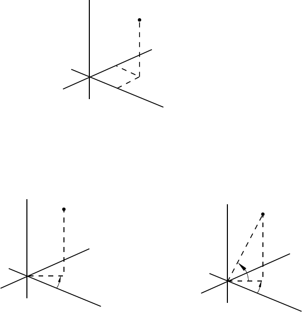
*PARAMETER SHAPE VARIATION
(X,Y,Z)
Rectangular Cartesian
(SYSTEM=R)
(default)
R
θ
Cylindrical
(SYSTEM=C)
(θ and φ are given in degrees)
(R,θ,φ)
θ
φ
Spherical
(SYSTEM=S)
Z
Y
X
YY
ZZ
X
X
(R,θ,Z)
Figure 16.3–1 Coordinate systems.
16.3–3
ABAQUS Version 6.1 Module: ID:
Printed on:
*PART
16.4 *PART: Begin a part definition.
This option is used to begin a part definition. It must be used in conjunction with the *ASSEMBLY, *END
PART, and *INSTANCE options.
Products: ABAQUS/Standard ABAQUS/Explicit
Type: Model data
Level: Model
References:
•“Defining an assembly,” Section 2.9.1 of the ABAQUS Analysis User’s Manual
•*END PART
Required parameter:
NAME
Set this parameter equal to a label that will be used to refer to the part.
There are no data lines associated with this option.
16.4–1
ABAQUS Version 6.1 Module: ID:
Printed on:
*PERIODIC
16.5 *PERIODIC: Define periodic symmetry for a cavity radiation heat transfer analysis.
This option is used to define cavity symmetry by periodic repetition in a given direction. It can be used only
following the *RADIATION SYMMETRY option.
Product: ABAQUS/Standard
Type: History data
Level: Step
References:
•“Cavity radiation,” Section 32.1.1 of the ABAQUS Analysis User’s Manual
•*RADIATION SYMMETRY
Required parameter:
TYPE
Set TYPE=2D to create a cavity composed of the cavity surface defined in the model and a series
of similar images generated by its repetition according to a two-dimensional distance vector. The
repeated images are bounded by lines parallel to line (see Figure 16.5–1). The distance vector
must be defined so that it points away from line and into the domain of the model. This option
can be used only for two-dimensional cases.
Set TYPE=3D to create a cavity composed of the cavity surface defined in the model and a
series of similar images generated by its repetition according to a three-dimensional distance vector.
The repeated images are bounded by planes parallel to plane (see Figure 16.5–2). The distance
vector must be defined so that it points away from plane and into the domain of the model. This
option can be used only for three-dimensional cases.
Set TYPE=ZDIR to create a cavity composed of the cavity surface defined in the model and
a series of similar images generated by its repetition in the z-direction. The repeated images are
bounded by lines of constant z-coordinate (see Figure 16.5–3). The z-distance vector must be
defined so that it points away from the z-constant periodic symmetry reference line and into the
domain of the model. This option can be used only for axisymmetric cases.
Optional parameter:
NR
Set this parameter equal to the number of repetitions used in the numerical calculation of the cavity
viewfactors resulting from the periodic symmetry. The result of this symmetry is a cavity composed
of the cavity surface defined in the model plus twice NR similar images, since the periodic symmetry
16.5–1
ABAQUS Version 6.1 Module: ID:
Printed on:
*PERIODIC
is assumed to apply both in the positive and negative directions of the distance vector. The default
value is NR=2.
Data line to define periodic symmetry of a two-dimensional cavity (TYPE=2D):
First (and only) line:
1. x-coordinate of point a(see Figure 16.5–1).
2. y-coordinate of point a.
3. x-coordinate of point b.
4. y-coordinate of point b.
5. x-component of periodic distance vector.
6. y-component of periodic distance vector.
Data lines to define periodic symmetry of a three-dimensional cavity (TYPE=3D):
First line:
1. x-coordinate of point a(see Figure 16.5–2).
2. y-coordinate of point a.
3. z-coordinate of point a.
4. x-coordinate of point b.
5. y-coordinate of point b.
6. z-coordinate of point b.
Second line:
1. x-coordinate of point c.
2. y-coordinate of point c.
3. z-coordinate of point c.
4. x-component of periodic distance vector.
5. y-component of periodic distance vector.
6. z-component of periodic distance vector.
Data line to define periodic symmetry of an axisymmetric cavity (TYPE=ZDIR):
First (and only) line:
1. z-coordinate of periodic symmetry reference line (see Figure 16.5–3).
2. z-component of periodic distance vector.
16.5–2
ABAQUS Version 6.1 Module: ID:
Printed on:
*PERIODIC
n =
2
x
-2d
-d
d
2d
y
a
b
Figure 16.5–1 *PERIODIC, TYPE=2D option.
16.5–3
ABAQUS Version 6.1 Module: ID:
Printed on:
*PERIODIC
z
x
y
2d
d
-d
-2
d
n = 2
c
a
b
Figure 16.5–2 *PERIODIC, TYPE=3D option.
16.5–4
ABAQUS Version 6.1 Module: ID:
Printed on:
*PERIODIC
-2d
-d
d
2d
n = 2
r
z
z = const periodic
symm reference lin
e
Figure 16.5–3 *PERIODIC, TYPE=ZDIR option.
16.5–5
ABAQUS Version 6.1 Module: ID:
Printed on:
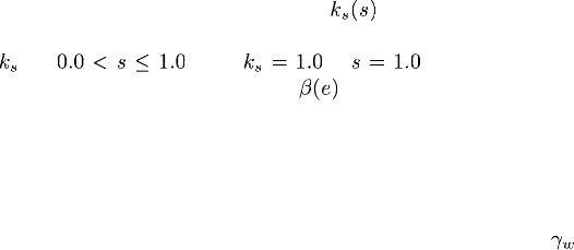
*PERMEABILITY
16.6 *PERMEABILITY: Define permeability for pore fluid flow.
This option is used to define permeability for pore fluid flow in problems involving seepage.
Product: ABAQUS/Standard
Type: Model data
Level: Model
Reference:
•“Permeability,” Section 20.7.2 of the ABAQUS Analysis User’s Manual
Optional parameters:
DEPENDENCIES
Set this parameter equal to the number of field variable dependencies included in the definition of the
permeability. If this parameter is omitted, it is assumed that the permeability is independent of field
variables. See “Specifying field variable dependence” in “Material data definition,” Section 16.1.2
of the ABAQUS Analysis User’s Manual, for more information.
This parameter can be used only in conjunction with TYPE=ISOTROPIC, ORTHOTROPIC,
or ANISOTROPIC.
TYPE
Set TYPE=ISOTROPIC (default) to define fully saturated isotropic permeability.
Set TYPE=ORTHOTROPIC to define fully saturated orthotropic permeability. Set
TYPE=ANISOTROPIC to define fully saturated anisotropic permeability.
Set TYPE=SATURATION to define ; this must be a repeated use of the option for the
same material and must follow the definition of fully saturated permeability. The definition must
give for ,with at .
Set TYPE=VELOCITY to define ; this must be a repeated use of the option for the same
material and must follow the definition of fully saturated permeability.
Required parameter when fully saturated material properties are defined:
SPECIFIC
Set this parameter equal to the specific weight of the wetting liquid, (units of FL−3 ). The actual
specific weight value must be given, and the GRAV distributed load type must be used to apply the
gravitational loading if a total pressure solution is required (see “Coupled pore fluid diffusion and
stress analysis,” Section 6.7.1 of the ABAQUS Analysis User’s Manual, for a discussion of total
and excess pressure solutions).
16.6–1
ABAQUS Version 6.1 Module: ID:
Printed on:
*PERMEABILITY
Data lines to define fully saturated isotropic permeability (TYPE=ISOTROPIC):
First line:
1. k.(UnitsofLT
−1 .)
2. Void ratio, e.
3. Temperature, .
4. First field variable.
5. Second field variable.
6. Etc.,uptofivefieldvariables.
Subsequent lines (only needed if the DEPENDENCIES parameter has a value greater than five):
1. Sixth field variable.
2. Etc., up to eight field variables per line.
Repeat this set of data lines as often as necessary to define the variation.
Data lines to define fully saturated orthotropic permeability (TYPE=ORTHOTROPIC):
First line:
1. . (Units of LT−1 .)
2. .
3. .
4. Void ratio, e.
5. Temperature, .
6. First field variable.
7. Second field variable.
8. Third field variable.
Subsequent lines (only needed if the DEPENDENCIES parameter has a value greater than three):
1. Fourth field variable.
2. Etc., up to eight field variables per line.
Repeat this set of data lines as often as necessary to define the variation.
Data lines to define fully saturated anisotropic permeability (TYPE=ANISOTROPIC):
First line:
1. . (Units of LT−1 .)
2. .
3. .
4. .
5. .
16.6–2
ABAQUS Version 6.1 Module: ID:
Printed on:
*PERMEABILITY
6. .
7. Void ratio, e.
8. Temperature, .
Subsequent lines (only needed if the DEPENDENCIES parameter is specified):
1. First field variable.
2. Second field variable.
3. Etc., up to eight field variables per line.
Repeat this set of data lines as often as necessary to define the variation.
Data lines to define the dependence of permeability on saturation of the wetting liquid, ks(s)
(TYPE=SATURATION):
First line:
1. . (Dimensionless.)
2. Saturation, s. (Dimensionless.)
Repeat this data line as often as necessary to define the variation. The table must provide at
.
Data lines to define the velocity coefficient, b(e) (TYPE=VELOCITY):
First line:
1. . (Units of TL−1 .) Only is allowed.
2. Void ratio, e.
Repeat this data line as often as necessary to define the variation.
16.6–3
ABAQUS Version 6.1 Module: ID:
Printed on:
*PHYSICAL CONSTANTS
16.7 *PHYSICAL CONSTANTS: Specify physical constants.
This option is used to define physical constants necessary for an analysis; since ABAQUS has no built-in
units, no default values are provided. If a physical constant required for the analysis is not given, ABAQUS
will issue a fatal error message. The units used for the constants must be consistent with the remaining input
data.
Products: ABAQUS/Standard ABAQUS/Explicit
Type: Model data
Level: Model
References:
•“Uncoupled heat transfer analysis,” Section 6.5.2 of the ABAQUS Analysis User’s Manual
•“Mass diffusion analysis,” Section 6.8.1 of the ABAQUS Analysis User’s Manual
•“Modeling fluid-filled cavities,” Section 11.5.1 of the ABAQUS Analysis User’s Manual
•“Rate-dependent plasticity: creep and swelling,” Section 18.2.4 of the ABAQUS Analysis User’s Manual
•“Hydrostatic fluid models,” Section 20.4.1 of the ABAQUS Analysis User’s Manual
•“Diffusivity,” Section 20.5.1 of the ABAQUS Analysis User’s Manual
•“Solubility,” Section 20.5.2 of the ABAQUS Analysis User’s Manual
•“Thermal contact properties,” Section 30.2.1 of the ABAQUS Analysis User’s Manual
•“Cavity radiation,” Section 32.1.1 of the ABAQUS Analysis User’s Manual
Optional parameters:
ABSOLUTE ZERO
Set this parameter equal to the absolute zero on the temperature scale chosen. For example, if the
analysis uses temperature in degrees Celsius, set ABSOLUTE ZERO=−273.15.
STEFAN BOLTZMANN
Set this parameter equal to the Stefan Boltzmann constant. For example, STEFAN
BOLTZMANN=5.669 × 10⁻⁸ Joule per sec m2Kelvin4in SI units.
UNIVERSAL GAS CONSTANT
Set this parameter equal to the universal gas constant. For example, UNIVERSAL GAS
CONSTANT=8.31434 Joule per mole Kelvin in SI units.
There are no data lines associated with this option.
16.7–1
ABAQUS Version 6.1 Module: ID:
Printed on:
*PIEZOELECTRIC
16.8 *PIEZOELECTRIC: Specify piezoelectric material properties.
This option is used to define the piezoelectric properties of a material.
Product: ABAQUS/Standard
Type: Model data
Level: Model
Reference:
•“Piezoelectric behavior,” Section 20.6.2 of the ABAQUS Analysis User’s Manual
Optional parameters:
DEPENDENCIES
Set this parameter equal to the number of field variables included in the definition of the piezoelectric
properties. If this parameter is omitted, the piezoelectric properties are assumed not to depend on
any field variables but may still depend on temperature. See “Specifying field variable dependence”
in “Material data definition,” Section 16.1.2 of the ABAQUS Analysis User’s Manual, for more
information.
TYPE
Set TYPE=S (default) to specify stress material coefficients for the piezoelectric property. Set
TYPE=E to specify strain material coefficients for the piezoelectric property.
Data lines to define the piezoelectric stress coefficient matrix (TYPE=S):
First line:
1. . (Units of FL−1 −1 .)
2. .
3. .
4. .
5. .
6. .
7. .
8. .
Second line:
1. .
16.8–1
ABAQUS Version 6.1 Module: ID:
Printed on:
*PIEZOELECTRIC
2. .
3. .
4. .
5. .
6. .
7. .
8. .
Third line:
1. .
2. .
3. Temperature, .
4. First field variable.
5. Second field variable.
6. Etc.,uptofivefieldvariables.
Subsequent lines (only needed if the DEPENDENCIES parameter has a value greater than five):
1. Sixth field variable.
2. Etc., up to eight field variables per line.
Repeat this set of data lines as often as necessary to define the piezoelectric properties as a function of
temperature and other predefined field variables.
Data lines to define the piezoelectric strain coefficient matrix (TYPE=E; for the shear
components these coefficients relate the engineering, and not the tensorial, shear strain
components to the components of the potential gradient vector):
First line:
1. . (Units of L −1 .)
2. .
3. .
4. .
5. .
6. .
7. .
8. .
Second line:
1. .
2. .
16.8–2
ABAQUS Version 6.1 Module: ID:
Printed on:
*PIEZOELECTRIC
3. .
4. .
5. .
6. .
7. .
8. .
Third line:
1. .
2. .
3. Temperature, .
4. First field variable.
5. Second field variable.
6. Etc.,uptofivefieldvariables.
Subsequent lines (only needed if the DEPENDENCIES parameter has a value greater than five):
1. Sixth field variable.
2. Etc., up to eight field variables per line.
Repeat this set of data lines as often as necessary to define the piezoelectric properties as a function of
temperature and other predefined field variables.
16.8–3
ABAQUS Version 6.1 Module: ID:
Printed on:
*PIPE-SOIL INTERACTION
16.9 *PIPE-SOIL INTERACTION: Specify element properties for pipe-soil interaction
elements.
This option is used to define properties for pipe-soil interaction elements. The *PIPE-SOIL STIFFNESS
option must follow immediately after this option.
Product: ABAQUS/Standard
Type: Model data
Level: Part, Part instance
References:
•“Pipe-soil interaction elements,” Section 26.13.1 of the ABAQUS Analysis User’s Manual
•“Pipe-soil interaction element library,” Section 26.13.2 of the ABAQUS Analysis User’s Manual
•*PIPE-SOIL STIFFNESS
Required parameter:
ELSET
Set this parameter equal to the name of the element set containing the pipe-soil interaction elements
for which properties are being defined.
Optional parameter:
ORIENTATION
Set this parameter equal to the name of the *ORIENTATION definition (“Orientations,”
Section 2.2.5 of the ABAQUS Analysis User’s Manual) that gives the orientation of the local
system used for material calculations.
There are no data lines associated with this option.
16.9–1
ABAQUS Version 6.1 Module: ID:
Printed on:
*PIPE-SOIL STIFFNESS
16.10 *PIPE-SOIL STIFFNESS: Define constitutive behavior for pipe-soil interaction
elements.
This option is used to define the constitutive behavior for pipe-soil interaction elements. It can be used only
in conjunction with the *PIPE-SOIL INTERACTION option. Repeat the option as needed to define behavior
in the different local directions.
Product: ABAQUS/Standard
Type: Model data
Level: Part, Part instance
References:
•“Pipe-soil interaction elements,” Section 26.13.1 of the ABAQUS Analysis User’s Manual
•“Pipe-soil interaction element library,” Section 26.13.2 of the ABAQUS Analysis User’s Manual
•“UMAT,” Section 1.1.31 of the ABAQUS User Subroutines Reference Manual
•*PIPE-SOIL INTERACTION
Optional parameters:
DEPENDENCIES
Set this parameter equal to the number of field variable dependencies included in the definition
of the material property values. If this parameter is omitted, it is assumed that the properties are
independent of field variables. See “Using the DEPENDENCIES parameters to define field variable
dependence” in “Material data definition,” Section 16.1.2 of the ABAQUS Analysis User’s Manual
for more information.
DIRECTION
Set this parameter equal to the direction in the local orientation system for which the behavior is
defined. The DIRECTION parameter can be set equal to a label or to a numerical value. Omit the
DIRECTION parameter to define an isotropic model. The DIRECTION parameter must be used to
define a constitutive model using the ASCE formulae.
Set DIRECTION=AXIAL (or DIRECTION=1) to specify behavior along the first local
direction.
Set DIRECTION=VERTICAL (or DIRECTION=2) to specify behavior along the second local
direction.
Set DIRECTION=HORIZONTAL (or DIRECTION=3) to specify behavior along the third
local direction.
16.10–1
ABAQUS Version 6.1 Module: ID:
Printed on:
*PIPE-SOIL STIFFNESS
TYPE
Set TYPE=LINEAR (default) to define a linear constitutive model.
Set TYPE=NONLINEAR to define a nonlinear constitutive model.
Set TYPE=CLAY to define a constitutive model using the ASCE formulae for clay. This
parameter must be used in conjunction with the DIRECTION parameter.
Set TYPE=SAND to define a constitutive model using the ASCE formulae for sand. This
parameter must be used in conjunction with the DIRECTION parameter.
Set TYPE=USER to indicate the constitutive behavior is defined in user subroutine UMAT.
The following optional parameters can be used only in combination with TYPE=USER:
PROPERTIES
Set this parameter equal to the number of property values needed as data in user subroutine UMAT.
The default is PROPERTIES=0.
VARIABLES
Set this parameter equal to the number of solution-dependent variables that must be stored for the
material calculations in user subroutine UMAT. The default is VARIABLES=1.
Data lines to define linear constitutive behavior (TYPE=LINEAR):
First line:
1. Interaction stiffness (force per relative displacement) corresponding to positive relative
displacements, .
2. Interaction stiffness (force per relative displacement) corresponding to negative relative
displacements, . The default is .
3. Temperature.
4. First field variable.
5. Second field variable.
6. Etc.,uptofivefieldvariables.
Subsequent lines (only needed if the DEPENDENCIES parameter has a value greater than five):
1. Sixth field variable.
2. Etc., up to eight field variables per line.
Repeat this set of data lines as often as necessary to define the stiffness as a function of temperature
and other predefined field variables.
Data lines to define nonlinear constitutive behavior (TYPE=NONLINEAR):
First line:
1. Force per unit length along pipeline.
2. Relative displacement.
16.10–2
ABAQUS Version 6.1 Module: ID:
Printed on:
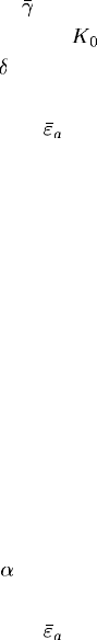
*PIPE-SOIL STIFFNESS
3. Temperature.
4. First field variable.
5. Second field variable.
6. Etc.,uptofivefieldvariables.
Subsequent lines (only needed if the DEPENDENCIES parameter has a value greater than five):
1. Sixth field variable.
2. Etc., up to eight field variables per line.
Repeat this set of data lines as often as necessary to define the force per unit length as a function of
relative displacement, temperature, and other predefined field variables.
Data lines to define constitutive behavior using the ASCE formula for sand in the axial direction
(TYPE=SAND, DIRECTION=AXIAL):
First line:
1. Effective unit weight of soil, .
2. Coefficient of soil pressure at rest, .
3. Interface angle of friction, . Givethevalueindegrees.
4. External pipe diameter, D.
5. Ultimate relative displacement, .
6. Temperature.
7. First field variable.
8. Second field variable.
Subsequent lines (only needed if the DEPENDENCIES parameter has a value greater than two):
1. Third field variable.
2. Etc., up to eight field variables per line.
Repeat this set of data lines as often as necessary to define the parameters for the ASCE formulae as a
function of temperature and other predefined field variables.
Data lines to define constitutive behavior using the ASCE formula for clay in the axial direction
(TYPE=CLAY, DIRECTION=AXIAL):
First line:
1. Undrained soil shear strength, S.
2. Empirical adhesion factor, .
3. External pipe diameter, D.
4. Ultimate relative displacement, .
5. Temperature.
6. First field variable.
16.10–3
ABAQUS Version 6.1 Module: ID:
Printed on:
*PIPE-SOIL STIFFNESS
7. Second field variable.
8. Third field variables.
Subsequent lines (only needed if the DEPENDENCIES parameter has a value greater than three):
1. Fourth field variable.
2. Etc., up to eight field variables per line.
Repeat this set of data lines as often as necessary to define the parameters for the ASCE formulae as a
function of temperature and other predefined field variables.
Data lines to define constitutive behavior using the ASCE formula for sand in the vertical
direction (TYPE=SAND, DIRECTION=VERTICAL):
First line:
1. Total unit weight of soil, .
2. Bearing capacity factor, .
3. Bearing capacity factor, .
4. Vertical uplift factor, .
5. Ultimate relative displacement for downward motion, .
6. Ultimate relative displacement for upward motion, .
7. Temperature.
8. First field variable.
Subsequent lines (only needed if the DEPENDENCIES parameter has a value greater than one):
1. Second field variable.
2. Etc., up to eight field variables per line.
Repeat this set of data lines as often as necessary to define the parameters for the ASCE formulae as a
function of temperature and other predefined field variables.
Data lines to define constitutive behavior using the ASCE formula for clay in the vertical
direction (TYPE=CLAY, DIRECTION=VERTICAL):
First line:
1. Bearing capacity factor, .
2. Vertical uplift factor, .
3. Ultimate relative displacement for downward motion, .
4. Ultimate relative displacement for upward motion, .
5. Temperature.
6. First field variable.
7. Second field variable.
8. Third field variable.
16.10–4
ABAQUS Version 6.1 Module: ID:
Printed on:
*PIPE-SOIL STIFFNESS
Subsequent lines (only needed if the DEPENDENCIES parameter has a value greater than three):
1. Fourth field variable.
2. Etc., up to eight field variables per line.
Repeat this set of data lines as often as necessary to define the parameters for the ASCE formulae as a
function of temperature and other predefined field variables.
Data lines to define constitutive behavior using the ASCE formula for sand in the horizontal
direction (TYPE=SAND, DIRECTION=HORIZONTAL):
First line:
1. Horizontal bearing capacity factor, .
2. Ultimate relative displacement, .
3. Temperature.
4. First field variable.
5. Second field variable.
6. Etc., up to five field variables per line.
Subsequent lines (only needed if the DEPENDENCIES parameter has a value greater than five):
1. Sixth field variable.
2. Etc., up to eight field variables per line.
Repeat this set of data lines as often as necessary to define the parameters for the ASCE formulae as a
function of temperature and other predefined field variables.
Data lines to define constitutive behavior using the ASCE formula for clay in the horizontal
direction (TYPE=CLAY, DIRECTION=HORIZONTAL):
First line:
1. Horizontal bearing capacity factor, .
2. Ultimate relative displacement, .
3. Temperature.
4. First field variable.
5. Second field variable.
6. Etc., up to five field variables per line.
Subsequent lines (only needed if the DEPENDENCIES parameter has a value greater than five):
1. Sixth field variable.
2. Etc., up to eight field variables per line.
Repeat this set of data lines as often as necessary to define parameters for the ASCE formulae as a
function of temperature and other predefined field variables.
16.10–5
ABAQUS Version 6.1 Module: ID:
Printed on:
*PIPE-SOIL STIFFNESS
Data lines if the constitutive behavior is defined in user subroutine UMAT (TYPE=USER):
First line:
1. Enter the data to be used as properties in user subroutine UMAT.
Repeat this data line as often as necessary to define properties required in UMAT. Enter eight values per
line.
16.10–6
ABAQUS Version 6.1 Module: ID:
Printed on:

*PLANAR TEST DATA
16.11 *PLANAR TEST DATA: Used to provide planar test (or pure shear) data (compression
and/or tension).
This option is used to provide planar test (or pure shear) data. It can be used only in conjunction with the
*HYPERELASTIC option, the *HYPERFOAM option, and the *MULLINS EFFECT option. This type of
test does not define the hyperelastic material constants fully; at the least, uniaxial or biaxial test data should
also be given.
Products: ABAQUS/Standard ABAQUS/Explicit
Type: Model data
Level: Model
Using planar test data to define a hyperelastic material
References:
•“Hyperelastic behavior of rubberlike materials,” Section 17.5.1 of the ABAQUS Analysis User’s Manual
•*HYPERELASTIC
Optional parameter:
SMOOTH
Include this parameter to apply a smoothing filter to the stress-strain data. If the parameter is omitted,
no smoothing is performed.
Set this parameter equal to the number nsuch that is equal to the total number of
data points in the moving window through which a cubic polynomial is fit using the least-squares
method. nshould be larger than 1. The default is SMOOTH=3.
Optional parameter when the *PLANAR TEST DATA option is used in conjunction with the
*HYPERELASTIC, MARLOW option:
DEPENDENCIES
Set this parameter equal to the number of field variable dependencies included in the definition of
the test data. If this parameter is omitted, it is assumed that the test data depend only on temperature.
See “Specifying field variable dependence” in “Material data definition,” Section 16.1.2 of the
ABAQUS Analysis User’s Manual, for more information.
16.11–1
ABAQUS Version 6.1 Module: ID:
Printed on:
*PLANAR TEST DATA
Data lines to specify planar test data for hyperelasticity other than the Marlow model:
First line:
1. Nominal stress, .
2. Nominal strain in the direction of loading, .
Repeat this data line as often as necessary to give the stress-strain data.
Data lines to specify planar test data for the Marlow model:
First line:
1. Nominal stress, .
2. Nominal strain, .
3. Nominal lateral strain, . Not needed if the POISSON parameter is specified on the
*HYPERELASTIC option or if the *VOLUMETRIC TEST DATA option is used.
4. Temperature, .
5. First field variable.
6. Second field variable.
7. Etc., up to four field variables.
Subsequent lines (only needed if the DEPENDENCIES parameter has a value greater than four):
1. Fifth field variable.
2. Etc., up to eight field variables per line.
Repeat this set of data lines as often as necessary to define the test data as a function of temperature
and other predefined field variables. Nominal strains and nominal stresses must be given in ascending
order.
Using planar test data to define an elastomeric foam
References:
•“Hyperelastic behavior in elastomeric foams,” Section 17.5.2 of the ABAQUS Analysis User’s Manual
•*HYPERFOAM
There are no parameters associated with this option.
Data lines to specify planar test data for a hyperfoam:
First line:
1. Nominal stress, .
2. Nominal strain in the direction of loading, .
16.11–2
ABAQUS Version 6.1 Module: ID:
Printed on:
*PLANAR TEST DATA
3. Nominal transverse strain, . Default is zero. Not needed if the POISSON parameter is
specifiedonthe*HYPERFOAM option.
Repeat this data line as often as necessary to give the stress-strain data.
Using planar test data to define the Mullins effect material model
References:
•“Mullins effect in rubberlike materials,” Section 17.6.1 of the ABAQUS Analysis User’s Manual
•“Energy dissipation in elastomeric foams,” Section 17.6.2 of the ABAQUS Analysis User’s Manual
•*MULLINS EFFECT
There are no parameters associated with this option.
Data lines to specify planar test data for defining the unloading-reloading response of the
Mullins effect material model:
First line:
1. Nominal stress, .
2. Nominal strain in the direction of loading, .
Repeat this data line as often as necessary to give the stress-strain data.
16.11–3
ABAQUS Version 6.1 Module: ID:
Printed on:
*PLASTIC
16.12 *PLASTIC: Specify a metal plasticity model.
This option is used to specify the plastic part of the material model for elastic-plastic materials that use the
Mises or Hill yield surface.
Products: ABAQUS/Standard ABAQUS/Explicit
Type: Model data
Level: Model
References:
•“Classical metal plasticity,” Section 18.2.1 of the ABAQUS Analysis User’s Manual
•“Models for metals subjected to cyclic loading,” Section 18.2.2 of the ABAQUS Analysis User’s Manual
•“Johnson-Cook plasticity,” Section 18.2.7 of the ABAQUS Analysis User’s Manual
•“UHARD,” Section 1.1.26 of the ABAQUS User Subroutines Reference Manual
Optional parameter:
HARDENING
Set HARDENING=ISOTROPIC (default) to specify isotropic hardening.
Set HARDENING=KINEMATIC to specify linear kinematic hardening.
Set HARDENING=COMBINED to specify nonlinear isotropic/kinematic hardening.
Set HARDENING=JOHNSON COOK to specify Johnson-Cook hardening in an
ABAQUS/Explicit analysis.
Set HARDENING=USER to define isotropic hardening in user subroutine UHARD in an
ABAQUS/Standard analysis.
Optional parameter for use with HARDENING=ISOTROPIC or HARDENING=COMBINED:
DEPENDENCIES
Set this parameter equal to the number of field variable dependencies included in the definition
of hardening behavior, in addition to temperature and possibly strain range. If this parameter is
omitted, the hardening behavior does not depend on field variables. See “Specifying field variable
dependence” in “Material data definition,” Section 16.1.2 of the ABAQUS Analysis User’s Manual,
for more information.
16.12–1
ABAQUS Version 6.1 Module: ID:
Printed on:

*PLASTIC
Optional parameter for use with HARDENING=ISOTROPIC:
RATE
Set this parameter equal to the equivalent plastic strain rate, , for which this stress-strain curve
applies.
Optional parameter for use with HARDENING=COMBINED:
DATA TYPE
Set DATA TYPE=HALF CYCLE (default) to specify stress versus plastic strain values of the first
half-cycle for calibrating the kinematic hardening parameters.
Set DATA TYPE=PARAMETERS to specify the calibrated kinematic hardening material
parameters directly.
Set DATA TYPE=STABILIZED to specify stress versus plastic strain values of a stabilized
cycle for calibrating the kinematic hardening parameters.
Optional parameter for use with HARDENING=USER:
PROPERTIES
This parameter applies only to ABAQUS/Standard analyses.
Set this parameter equal to the number of property values needed as data in user subroutine
UHARD. The default is PROPERTIES=0.
Data lines for HARDENING=ISOTROPIC or HARDENING=COMBINED with DATA TYPE=HALF
CYCLE:
First line:
1. Yield stress.
2. Plastic strain.
3. Temperature.
4. First field variable.
5. Second field variable.
6. Etc.,uptofivefieldvariables.
Subsequent lines (only needed if the DEPENDENCIES parameter has a value greater than five):
1. Sixth field variable.
2. Etc., up to eight field variables per line.
Repeat this set of data lines as often as necessary to define the dependence of yield stress on plastic
strain and, if needed, on temperature and other predefined field variables.
16.12–2
ABAQUS Version 6.1 Module: ID:
Printed on:
*PLASTIC
Data lines for HARDENING=COMBINED with DATA TYPE=STABILIZED:
First line:
1. Yield stress.
2. Plastic strain.
3. Strain range.
4. Temperature.
5. First field variable.
6. Second field variable.
7. Etc., up to four field variables.
Subsequent lines (only needed if the DEPENDENCIES parameter has a value greater than four):
1. Fifth field variable.
2. Etc., up to eight field variables per line.
Repeat this set of data lines as often as necessary to define the dependence of yield stress on plastic
strain and, if needed, on strain range, temperature, and other predefined field variables.
Data lines for HARDENING=COMBINED with DATA TYPE=PARAMETERS:
First line:
1. Yield stress at zero plastic strain.
2. Kinematic hardening parameter, C.
3. Kinematic hardening parameter, .
4. Temperature.
5. First field variable.
6. Second field variable.
7. Etc., up to four field variables.
Subsequent lines (only needed if the DEPENDENCIES parameter has a value greater than four):
1. Fifth field variable.
2. Etc., up to eight field variables per line.
Repeat this set of data lines as often as necessary to define the dependence of yield stress and
kinematic hardening parameter Con temperature and other predefined field variables. cannot depend
on temperature and predefined field variables.
Data lines for HARDENING=KINEMATIC:
First line:
1. Yield stress.
16.12–3
ABAQUS Version 6.1 Module: ID:
Printed on:

*PLASTIC
2. Plastic strain.
3. Temperature, if temperature dependent.
Repeat this data line a maximum of two times to define linear kinematic hardening independent of
temperature. Repeat this set of data lines as often as necessary to define a variation of the linear
kinematic hardening modulus with respect to temperature.
Data line for HARDENING=JOHNSON COOK:
First (and only) line:
1. A.
2. B.
3. n.
4. m.
5. Melting temperature, .
6. Transition temperature, .
Data lines for HARDENING=USER with PROPERTIES:
First line:
1. Give the hardening properties, eight per line.
Repeat this data line as often as necessary to define all hardening properties.
16.12–4
ABAQUS Version 6.1 Module: ID:
Printed on:
*PLASTIC AXIAL
16.13 *PLASTIC AXIAL: Define plastic axial force for frame elements.
This option can be used only in conjunction with the *FRAME SECTION option. It describes the axial force
in a frame element as a function of the axial plastic displacement.
Product: ABAQUS/Standard
Type: Model data
Level: Part, Part instance
References:
•“Frame section behavior,” Section 23.4.2 of the ABAQUS Analysis User’s Manual
•*FRAME SECTION
There are no parameters associated with this option.
Data lines to define the variation of axial yield force with plastic displacement:
First line:
1. Axial yield force.
2. Plastic axial displacement.
Repeat this data line as often as necessary to define the relationship between the axial force and the
axial plastic displacement. At least three pairs of data are required.
16.13–1
ABAQUS Version 6.1 Module: ID:
Printed on:

*PLASTIC M1
16.14 *PLASTIC M1: Define the first plastic bending moment behavior for frame elements.
This option can be used only in conjunction with the *FRAME SECTION option. It describes the bending
moment in a frame element as a function of the plastic rotation about the first cross-section direction.
Product: ABAQUS/Standard
Type: Model data
Level: Part, Part instance
References:
•“Frame section behavior,” Section 23.4.2 of the ABAQUS Analysis User’s Manual
•*FRAME SECTION
There are no parameters associated with this option.
Data lines to define the variation of yield moment M1
0with plastic rotation:
First line:
1. Bending yield moment about the first cross-section direction.
2. Plastic rotation about the first cross-section direction.
Repeat this data line as often as necessary to define the relationship between the bending moment and
the plastic rotation about the first cross-section axis. At least three pairs of data are required.
16.14–1
ABAQUS Version 6.1 Module: ID:
Printed on:

*PLASTIC M2
16.15 *PLASTIC M2: Define the second plastic bending moment behavior for frame
elements.
This option can be used only in conjunction with the *FRAME SECTION option and is available only for
FRAME3D elements. It describes the bending moment in a frame element as a function of the plastic rotation
about the second cross-section direction.
Product: ABAQUS/Standard
Type: Model data
Level: Part, Part instance
References:
•“Frame section behavior,” Section 23.4.2 of the ABAQUS Analysis User’s Manual
•*FRAME SECTION
There are no parameters associated with this option.
Data lines to define the variation of yield moment M2
0with plastic rotation:
First line:
1. Bending yield moment about the second cross-section direction.
2. Plastic rotation about the second cross-section direction.
Repeat this data line as often as necessary to define the relationship between the bending moment and
the plastic rotation about the second cross-section axis. At least three pairs of data are required.
16.15–1
ABAQUS Version 6.1 Module: ID:
Printed on:

*PLASTIC TORQUE
16.16 *PLASTIC TORQUE: Define the plastic torsional moment behavior for frame
elements.
This option can be used only in conjunction with the *FRAME SECTION option and is available only for
FRAME3D elements. It describes the torsional moment in a frame element as a function of the plastic rotation
about the element’s axis.
Product: ABAQUS/Standard
Type: Model data
Level: Part, Part instance
References:
•“Frame section behavior,” Section 23.4.2 of the ABAQUS Analysis User’s Manual
•*FRAME SECTION
There are no parameters associated with this option.
Data lines to define the variation of torsional yield moment with plastic rotation:
First line:
1. Torsional yield moment, .
2. Plastic rotation about the element’s axis.
Repeat this data line as often as necessary to define the relationship between the torsional moment and
the plastic rotation. At least three pairs of data are required.
16.16–1
ABAQUS Version 6.1 Module: ID:
Printed on:
*POROUS BULK MODULI
16.17 *POROUS BULK MODULI: Define bulk moduli for soils and rocks.
This option is used to define the bulk moduli of solid grains and a permeating fluid such that their
compressibility can be considered in the analysis of a porous medium. The *POROUS BULK MODULI
option cannot be used with the porous metal plasticity material model.
Product: ABAQUS/Standard
Type: Model data
Level: Model
Reference:
•“Porous bulk moduli,” Section 20.7.3 of the ABAQUS Analysis User’s Manual
There are no parameters associated with this option.
Data lines to define bulk moduli:
First line:
1. Bulk modulus of solid grains. (Units of FL−2 .) If this entry is blank or zero, this value is
assumedtobeinfinite.
2. Bulk modulus of permeating fluid. (Units of FL−2 .) If this entry is blank or zero, this value is
assumedtobeinfinite.
3. Temperature.
Repeat this data line as often as necessary to define the dependence of the bulk moduli on temperature.
16.17–1
ABAQUS Version 6.1 Module: ID:
Printed on:
*POROUS ELASTIC
16.18 *POROUS ELASTIC: Specify elastic material properties for porous materials.
This option is used to define the elastic parameters for porous materials.
Product: ABAQUS/Standard
Type: Model data
Level: Model
Reference:
•“Elastic behavior of porous materials,” Section 17.3.1 of the ABAQUS Analysis User’s Manual
Optional parameters:
DEPENDENCIES
Set this parameter equal to the number of field variable dependencies included in the definition
of the parameters, in addition to temperature. If this parameter is omitted, it is assumed that the
parameters depend only on temperature. See “Specifying field variable dependence” in “Material
data definition,” Section 16.1.2 of the ABAQUS Analysis User’s Manual, for more information.
SHEAR
Set SHEAR=G to define the deviatoric behavior with a constant shear modulus G.Set
SHEAR=POISSON (default) to compute the instantaneous shear modulus from the bulk modulus
and Poisson’s ratio. The Poisson’s ratio should be given on the data lines.
Data lines to define the deviatoric behavior with a constant shear modulus G:
First line:
1. Value of the logarithmic bulk modulus, . (Dimensionless.)
2. Value of the shear modulus, G.
3. Value of the elastic tensile limit, . (This value cannot be negative.)
4. Temperature, .
5. First field variable.
6. Etc., up to four field variables.
Subsequent lines (only needed if the DEPENDENCIES parameter has a value greater than four):
1. Fifth field variable.
16.18–1
ABAQUS Version 6.1 Module: ID:
Printed on:
*POROUS ELASTIC
2. Etc., up to eight field variables per line.
Repeat this set of data lines as often as necessary to define the dependence of the material parameters
,G, and on temperature and field variables.
Data lines to define the instantaneous shear modulus from the bulk modulus and Poisson’s ratio:
First line:
1. Value of the logarithmic bulk modulus, . (Dimensionless.)
2. Value of Poisson’s ratio, .
3. Value of the elastic tensile limit, . (This value cannot be negative.)
4. Temperature, .
5. First field variable.
6. Etc., up to four field variables.
Subsequent lines (only needed if the DEPENDENCIES parameter has a value greater than four):
1. Fifth field variable.
2. Etc., up to eight field variables per line.
Repeat this set of data lines as often as necessary to define the dependence of the material parameters
,, and on temperature and field variables.
16.18–2
ABAQUS Version 6.1 Module: ID:
Printed on:
*POROUS FAILURE CRITERIA
16.19 *POROUS FAILURE CRITERIA: Define porous material failure criteria for a *POROUS
METAL PLASTICITY model.
This option is used to specify the material failure criteria in a porous metal.
Product: ABAQUS/Explicit
Type: Model data
Level: Model
References:
•*POROUS METAL PLASTICITY
•“Porous metal plasticity,” Section 18.2.9 of the ABAQUS Analysis User’s Manual
There are no parameters associated with this option.
Data line to define material failure criteria:
First (and only) line:
1. Void volume fraction at total failure, . The default is 1.
2. Critical void volume fraction (threshold of rapid loss of stress carrying capacity), .The
default is .
16.19–1
ABAQUS Version 6.1 Module: ID:
Printed on:
*POROUS METAL PLASTICITY
16.20 *POROUS METAL PLASTICITY: Specify a porous metal plasticity model.
This option is used to specify the porous part of the porous metal plasticity model.
The *POROUS METAL PLASTICITY option can be used in conjunction with the *VOID
NUCLEATION option to define the nucleation of voids. In an ABAQUS/Explicit analysis it can also be used
in conjunction with the *POROUS FAILURE CRITERIA option to specify the material failure criteria.
Products: ABAQUS/Standard ABAQUS/Explicit
Type: Model data
Level: Model
References:
•“Porous metal plasticity,” Section 18.2.9 of the ABAQUS Analysis User’s Manual
•*VOID NUCLEATION
•*POROUS FAILURE CRITERIA
Optional parameters:
DEPENDENCIES
Set this parameter equal to the number of field variable dependencies, in addition to temperature,
included in the definition of the ,,and parameters. If this parameter is omitted, ,,and
may depend only on temperature. See “Specifying field variable dependence” in “Material data
definition,” Section 16.1.2 of the ABAQUS Analysis User’s Manual, for more information.
RELATIVE DENSITY
Set this parameter equal to , the initial relative density of the material. If this parameter is omitted,
the initial relative density is interpolated from the values given in the *INITIAL CONDITIONS,
TYPE=RELATIVE DENSITY option.
Data lines to define porous metal plasticity:
First line:
1. .
2. .
3. .
4. Temperature.
5. First field variable.
16.20–1
ABAQUS Version 6.1 Module: ID:
Printed on:
*POROUS METAL PLASTICITY
6. Second field variable.
7. Etc., up to four field variables.
Subsequent lines (only needed if the DEPENDENCIES parameter has a value greater than four):
1. Fifth field variable.
2. Etc., up to eight field variables per line.
Repeat this set of data lines as often as necessary to define the dependence of ,, and on
temperature and other predefined field variables.
16.20–2
ABAQUS Version 6.1 Module: ID:
Printed on:
*POST OUTPUT
16.21 *POST OUTPUT: Postprocess for output from the restart file.
This option can be used only for postprocessing to recover additional printed (.dat), output database (.odb),
and results file (.fil) output from the restart file of a previous analysis.
Product: ABAQUS/Standard
Type: History data
Level: Model
References:
•“Output,” Section 4.1.1 of the ABAQUS Analysis User’s Manual
•“Restarting an analysis,” Section 9.1.1 of the ABAQUS Analysis User’s Manual
Required parameter:
STEP
Set this parameter equal to the step number from which output is required.
Optional parameter:
ITERATION
This parameter applies only to postprocessing a direct cyclic analysis (see “Direct cyclic analysis,”
Section 6.2.6 of the ABAQUS Analysis User’s Manual).
Set this parameter equal to the iteration number in a direct cyclic analysis from which additional
output is being requested.
Data lines to request output from specified increments if the ITERATION is omitted:
First line:
1. First increment number at which additional output is being requested.
2. Second increment number at which additional output is being requested.
3. Etc., up to eight increments per line.
Repeat this data line as often as necessary to define the increments at which output is required.
To recover additional output from a previous direct cyclic analysis when the ITERATION
parameter is included:
No data lines are needed when the ITERATION parameter is specified.
16.21–1
ABAQUS Version 6.1 Module: ID:
Printed on:
*POTENTIAL
16.22 *POTENTIAL: Define an anisotropic yield/creep model.
This option is used to define stress ratios for anisotropic yield and creep behavior. It can be used
only in conjunction with material models defined by the *CREEP option, the *PLASTIC option
(HARDENING=ISOTROPIC, KINEMATIC, or COMBINED; the *POTENTIAL option can be used in
conjunction with COMBINED hardening only in ABAQUS/Explicit), and/or the *VISCOUS option.
Products: ABAQUS/Standard ABAQUS/Explicit
Type: Model data
Level: Model
References:
•“Classical metal plasticity,” Section 18.2.1 of the ABAQUS Analysis User’s Manual
•“Models for metals subjected to cyclic loading,” Section 18.2.2 of the ABAQUS Analysis User’s Manual
•“Rate-dependent plasticity: creep and swelling,” Section 18.2.4 of the ABAQUS Analysis User’s Manual
•“Anisotropic yield/creep,” Section 18.2.6 of the ABAQUS Analysis User’s Manual
•“Two-layer viscoplasticity,” Section 18.2.11 of the ABAQUS Analysis User’s Manual
Optional parameter:
DEPENDENCIES
Set this parameter equal to the number of field variable dependencies included in the definition
of in addition to temperature. If this parameter is omitted, it is assumed that the anisotropy
ratios are constant or depend only on temperature. See “Specifying field variable dependence”
in “Material data definition,” Section 16.1.2 of the ABAQUS Analysis User’s Manual, for more
information.
Data lines used to define stress ratios:
First line:
1. .
2. .
3. .
4. .
5. .
6. .
16.22–1
ABAQUS Version 6.1 Module: ID:
Printed on:

*POTENTIAL
7. Temperature.
8. First field variable.
Subsequent lines (only needed if the DEPENDENCIES parameter has a value greater than one):
1. Second field variable.
2. Etc., up to eight field variables per line.
Repeat this set of data lines as often as necessary to define the dependence of on temperature and
other field variables.
16.22–2
ABAQUS Version 6.1 Module: ID:
Printed on:
*PREPRINT
16.23 *PREPRINT: Select printout for the analysis input file processor.
This option is used to select the printout that will be obtained from the analysis input file processor.
Products: ABAQUS/Standard ABAQUS/Explicit
Type: Model data
Level: Model
Reference:
•“Output,” Section 4.1.1 of the ABAQUS Analysis User’s Manual
Optional parameters:
CONTACT
This parameter applies only to ABAQUS/Standard analyses.
Set CONTACT=YES to print detailed information about the contact constraints generated by
the contact pair definition data. Set CONTACT=NO (default) to suppress this printout.
ECHO
Set ECHO=YES to print an echo of the input data. Set ECHO=NO (default) to suppress this printout.
HISTORY
Set HISTORY=YES to print history data. Set HISTORY=NO (default) to suppress this printout.
MODEL
Set MODEL=YES to print model definition data. Set MODEL=NO (default) to suppress this
printout.
PARSUBSTITUTION
Set PARSUBSTITUTION=YES to print the modified version of the original input file that is free
of input model parametrization. Set PARSUBSTITUTION=NO (default) to suppress this printout.
PARVALUES
Set PARVALUES=YES to print a modified version of the original input file showing the parameters
used for model parametrization and their values. Set PARVALUES=NO (default) to suppress this
printout.
There are no data lines associated with this option.
16.23–1
ABAQUS Version 6.1 Module: ID:
Printed on:
*PRESSURE PENETRATION
16.24 *PRESSURE PENETRATION: Specify pressure penetration loads with surface-based
contact.
This option is used to prescribe pressure penetration loading simulated with surface-based contact.
Product: ABAQUS/Standard
Type: History data
Level: Step
Reference:
•“Pressure penetration loading,” Section 30.1.7 of the ABAQUS Analysis User’s Manual
Required parameters:
MASTER
Set this parameter equal to the name of the master surface of the contact pair used in the pressure
penetration analysis.
SLAVE
Set this parameter equal to the name of the slave surface of the contact pair used in the pressure
penetration analysis.
Optional parameters:
AMPLITUDE
Set this parameter equal to the name of the amplitude curve that defines the variation of the
fluid pressure during the step. If this parameter is omitted, the reference magnitude is applied
immediately at the beginning of the step or ramped up linearly over the step, depending on the
value assigned to the AMPLITUDE parameter on the *STEP option (see “Procedures: overview,”
Section 6.1.1 of the ABAQUS Analysis User’s Manual).
LOAD CASE
Set this parameter equal to the load case number. This parameter is used only in *STEADY STATE
DYNAMICS analyses (direct or modal—see “Direct-solution steady-state dynamic analysis,”
Section 6.3.4 of the ABAQUS Analysis User’s Manual, and “Mode-based steady-state dynamic
analysis,” Section 6.3.8 of the ABAQUS Analysis User’s Manual). It is ignored in all other
procedures. LOAD CASE=1 (default) defines the real (in-phase) part of the loading, and LOAD
CASE=2 defines the imaginary (out-of-phase) part of the loading.
16.24–1
ABAQUS Version 6.1 Module: ID:
Printed on:
*PRESSURE PENETRATION
OP
Set OP=MOD (default) for existing pressure penetration loads to remain, with this option modifying
existing pressure penetration loads or defining additional pressure penetration loads.
Set OP=NEW if all existing pressure penetration loads applied to the model should be removed.
New pressure penetration loads can be defined.
PENETRATION TIME
Set this parameter equal to a time period over which the fluid pressure on newly penetrated contact
surface segments is ramped up to the current magnitude. The default penetration time period is
chosen to be 0.001 of the current step time. This parameter will be neglected in a linear perturbation
analysis, in which case the current fluid pressure will be applied immediately once the pressure
penetration criterion is satisfied.
Data lines to define the pressure penetration loads:
First line:
1. A node on the slave surface that is exposed to the fluid.
2. A node on the master surface that is exposed to the fluid. This field should be left blank if the
master surface is an analytical rigid surface.
3. Fluid pressure magnitude.
4. Enter the critical contact pressure below which fluid penetration starts to occur. The higher
this value, the easier the fluid penetrates. The default is zero, in which case fluid penetration
occurs only if contact is lost.
Repeat this data line as often as necessary to define fluid penetrations from different locations on the
surface, possibly with different fluid pressure magnitudes. Alternatively, the *PRESSURE PENETRATION
option can be repeated (if, for example, a different amplitude reference is needed).
16.24–2
ABAQUS Version 6.1 Module: ID:
Printed on:
*PRESSURE STRESS
16.25 *PRESSURE STRESS: Specify equivalent pressure stress as a predefined field for a
mass diffusion analysis.
This option can be used only in a *MASS DIFFUSION analysis to specify pressure as a predefined field. The
user defines equivalent pressure stresses at the nodes, and ABAQUS/Standard interpolates the pressure to the
material points.
Product: ABAQUS/Standard
Type: History data
Level: Step
References:
•“Mass diffusion analysis,” Section 6.8.1 of the ABAQUS Analysis User’s Manual
•“Predefined fields,” Section 27.6.1 of the ABAQUS Analysis User’s Manual
Optional parameters for using the data line format:
AMPLITUDE
Set this parameter equal to the name of the amplitude curve that gives the time variation of the
pressure throughout the step. If the AMPLITUDE parameter is omitted, the reference magnitude is
applied either immediately at the beginning of the step or linearly over the step, depending on the
value assigned to the AMPLITUDE parameter on the *STEP option (see “Procedures: overview,”
Section 6.1.1 of the ABAQUS Analysis User’s Manual).
INPUT
Set this parameter equal to the name of the alternate input file containing the data lines for this
option. See “Input syntax rules,” Section 1.2.1 of the ABAQUS Analysis User’s Manual, for the
syntax of such file names. If this parameter is omitted, it is assumed that the data follow the keyword
line.
OP
Set OP=MOD (default) for existing *PRESSURE STRESS values to remain, with this option
modifying existing values or defining additional values.
Set OP=NEW if all existing *PRESSURE STRESS values should be removed. New pressure
stress values can be defined.
A pressure that is removed via OP=NEW is reset to the value given on the *INITIAL
CONDITIONS option or to zero if no initial pressure was defined. If pressures are being returned
to their initial condition values, the AMPLITUDE parameter described above does not apply.
Rather, the AMPLITUDE parameter given on the *STEP option governs the behavior. If pressures
16.25–1
ABAQUS Version 6.1 Module: ID:
Printed on:
*PRESSURE STRESS
are being reset to new values (not to initial conditions) via OP=NEW, the AMPLITUDE parameter
described above applies.
Required parameter for reading equivalent pressure stresses from the results file:
FILE
Set this parameter equal to the name of the results file (including the optional .fil extension) from
which the data are read. See “Input syntax rules,” Section 1.2.1 of the ABAQUS Analysis User’s
Manual, for the syntax of such file names.
Optional parameters for reading equivalent pressure stresses from the results file:
BSTEP
Set this parameter equal to the step number (of the analysis whose results file is being used as input
to this option) that begins the history data to be read. If no value is supplied, ABAQUS/Standard
will begin reading pressure data from the first step available on the results file.
BINC
Set this parameter equal to the increment number (of the analysis whose results file is being
used as input to this option) that begins the history data to be read. If no value is supplied,
ABAQUS/Standard will begin reading pressure data from the first increment available (excluding
any zero increments) for step BSTEP on the results file.
ESTEP
Set this parameter equal to the step number (of the analysis whose results file is being used as input
to this option) that ends the history data to be read. If no value is supplied, ESTEP is taken as equal
to BSTEP.
EINC
Set this parameter equal to the increment number (of the analysis whose results file is being used as
input to this option) that ends the history data to be read. If no value is supplied, EINC is taken as
the last available increment of step ESTEP on the results file.
Required parameter for defining data in user subroutine UPRESS:
USER
Include this parameter to indicate that user subroutine UPRESS will be used to define equivalent
pressure stress values. UPRESS will be called for each node given on the data lines. If values are
also given on the data lines, these values will be ignored. If a results file has been specified in
addition to user subroutine UPRESS, values read from the results file will be passed into UPRESS
for possible modification.
16.25–2
ABAQUS Version 6.1 Module: ID:
Printed on:
*PRESSURE STRESS
Data lines to define pressures using the data line format:
First line:
1. Node set or node number. If a node set label is given, all nodes in this set must have identical
initial pressures.
2. Reference pressure value (positive in compression). If the AMPLITUDE parameter is present,
this value will be modified by the AMPLITUDE specification.
Repeat this line as often as necessary to define the pressure at different nodes or node sets.
To read pressures from an ABAQUS/Standard results file (FILE):
No data lines are used when pressure data are read from a results file.
Data lines to define equivalent pressure stresses using user subroutine UPRESS:
First line:
1. Node set or node number. If a node set label is given, all nodes in this set must have identical
initial equivalent pressure stress values.
Repeat this line as often as necessary. UPRESS will be called for each node listed.
16.25–3
ABAQUS Version 6.1 Module: ID:
Printed on:
*PRESTRESS HOLD
16.26 *PRESTRESS HOLD: Keep rebar prestress constant during initial equilibrium
solution.
This option is used within a *STATIC step (“Static stress analysis,” Section 6.2.2 of the ABAQUS Analysis
User’s Manual) to keep the stress in some or all of the rebar constant during the initial equilibrium solution.
Product: ABAQUS/Standard
Type: History data
Level: Step
Reference:
•“Defining reinforcement,” Section 2.2.3 of the ABAQUS Analysis User’s Manual
There are no parameters associated with this option.
Data line to hold the prestress constant:
First line:
1. Element set name.
2. Rebar name. The stress in all rebar included in the above element set will be held fixed
throughout the step.
3. Etc.
Repeat this data line as often as necessary. Give four pairs of data per line.
16.26–1
ABAQUS Version 6.1 Module: ID:
Printed on:
*PRE-TENSION SECTION
16.27 *PRE-TENSION SECTION: Associate a pre-tension node with a pre-tension section.
This option is used to associate a pre-tension node with a pre-tension section.
Product: ABAQUS/Standard
Type: Model data
Level: Part, Part instance, Assembly
Reference:
•“Prescribed assembly loads,” Section 27.5.1 of the ABAQUS Analysis User’s Manual
Required parameter:
NODE
Set this parameter equal to either the pre-tension node number or the name of a node set containing
the pre-tension node. If the name of a node set is chosen, the node set must contain exactly one
node.
Required, mutually exclusive parameters:
ELEMENT
Set this parameter equal to either the element number of the truss or beam element used to define
the pre-tension section or the name of an element set containing the truss or beam element used to
define the pre-tension section. If the name of an element set is chosen, the element set must contain
exactly one element.
SURFACE
Set this parameter equal to the name of the surface definition (*SURFACE) that defines the pre-
tension section (when continuum elements are used).
Data line to define the normal to the section (optional):
First (and only) data line:
1. First component of the normal.
2. Second component of the normal.
3. Third component of the normal.
16.27–1
ABAQUS Version 6.1 Module: ID:
Printed on:
*PRE-TENSION SECTION
If the data line is omitted, ABAQUS/Standard will compute an average normal to the pre-tension
section for continuum elements. For truss or beam elements the default normal points from the first
to the last node in the element connectivity.
16.27–2
ABAQUS Version 6.1 Module: ID:
Printed on:
*PRINT
16.28 *PRINT: Request or suppress output to the message file in an ABAQUS/Standard
analysis or to the status file in an ABAQUS/Explicit analysis.
This option is used to obtain or suppress detailed printout in the message (.msg) file in an ABAQUS/Standard
analysis or in the status (.sta) file in an ABAQUS/Explicit analysis.
Products: ABAQUS/Standard ABAQUS/Explicit
Type: History data
Level: Step
References:
•“Output,” Section 4.1.1 of the ABAQUS Analysis User’s Manual
Optional parameters in ABAQUS/Standard analyses:
ADAPTIVE MESH
Set ADAPTIVE MESH=YES to request detailed output during adaptive mesh smoothing. The
default is ADAPTIVE MESH=NO.
CONTACT
Set CONTACT=YES to request detailed output of points that are contacting or separating in
interface and gap problems. This output is useful in difficult contact problems to track the
development of the solution during iteration within an increment. The default is CONTACT=NO.
FREQUENCY
Set this parameter equal to the output frequency, in increments. The output will always be printed
at the last increment of each step unless FREQUENCY=0. The default is FREQUENCY=1. Set
FREQUENCY=0 to suppress the output.
MODEL CHANGE
Set MODEL CHANGE=YES to request detailed output of which elements are being removed
or reactivated in the step. This output includes the new original coordinates and normals of
elements being reactivated strain free in a large-displacement analysis. The default is MODEL
CHANGE=NO.
PLASTICITY
Set PLASTICITY=YES to request detailed output of element and integration point numbers for
which the plasticity algorithms have failed to converge in the material routines. This output is
useful to determine the location in the mesh and the plasticity model for which ABAQUS/Standard
is encountering material model difficulties. This information may help in identifying modeling
problems as well as material parameter specification problems. The default is PLASTICITY=NO.
16.28–1
ABAQUS Version 6.1 Module: ID:
Printed on:
*PRINT
RESIDUAL
Set RESIDUAL=YES (default) if the output of equilibrium residuals is to be given during the
equilibrium iterations. Set RESIDUAL=NO to suppress the output.
SOLVE
Set SOLVE=YES to request information regarding the actual number of equations and the memory
requirement in each iteration. The default is SOLVE=NO.
Optional parameters in ABAQUS/Explicit analyses:
ALLKE
Set ALLKE=YES to request that a column containing the total kinetic energy be printed in the status
file. Set ALLKE=NO to suppress this printout. The default is ALLKE=YES.
CRITICAL ELEMENT
Set CRITICAL ELEMENT=YES to request that a column listing the element that has the smallest
stable time increment and a column listing the value be printed in the status file. Set CRITICAL
ELEMENT=NO to suppress this printout. The default is CRITICAL ELEMENT=YES.
DMASS
Set DMASS=YES to request that a column containing the percent change in total mass of the model
due to mass scaling be printed in the status file. Set DMASS=NO to suppress this printout. The
default is DMASS=NO unless active mass scaling is present in the step. *FIXED MASS SCALING
propagated from a previous step is not considered to be active mass scaling.
ETOTAL
Set ETOTAL=YES to request that a column containing the energy balance of the model be printed
in the status file. Set ETOTAL=NO to suppress this printout. The default is ETOTAL=NO.
There are no data lines associated with this option.
16.28–2
ABAQUS Version 6.1 Module: ID:
Printed on:
*PSD-DEFINITION
16.29 *PSD-DEFINITION: Define a cross-spectral density frequency function for random
response loading.
This option is used to define a frequency function for reference in the *CORRELATION option to define the
frequency dependence of the random loading in the *RANDOM RESPONSE analysis procedure.
Product: ABAQUS/Standard
Type: Model data
Level: Model
References:
•“Random response analysis,” Section 6.3.11 of the ABAQUS Analysis User’s Manual
•“UPSD,” Section 1.1.38 of the ABAQUS User Subroutines Reference Manual
•*CORRELATION
•*RANDOM RESPONSE
Required parameter:
NAME
Set this parameter equal to a label that will be used to refer to this frequency function.
Optional parameters:
DB REFERENCE
Set this parameter equal to the reference power value, in (load units)2. This parameter is required
when the frequency function is given in decibel units (TYPE=DB).
G
Set this parameter equal to the reference gravity acceleration; for example, 9.81 m/s2. The default
is G=1.0. This parameter can be used only with TYPE=BASE.
INPUT
Set this parameter equal to the name of the alternate input file containing the data lines for this
option. See “Input syntax rules,” Section 1.2.1 of the ABAQUS Analysis User’s Manual, for the
syntax of such file names. If this parameter is omitted, it is assumed that the data follow the keyword
line.
TYPE
Set TYPE=BASE if this frequency function will be used to define a base motion.
16.29–1
ABAQUS Version 6.1 Module: ID:
Printed on:
*PSD-DEFINITION
Set TYPE=FORCE (default) if this frequency function is given directly in power units.
Set TYPE=DB if this frequency function is defined in decibel units (see below). This option
cannot be used with the USER parameter.
USER
Include this parameter if the frequency function is defined in user subroutine UPSD. If this parameter
is included, no data lines are needed.
Data lines for TYPE=BASE or TYPE=FORCE:
First line:
1. Real part of the frequency function, in units2per frequency.
2. Imaginary part of the frequency function, in units2per frequency.
3. Frequency, in cycles/time.
Repeat this data line as often as necessary to define the frequency function.
Data lines for TYPE=DB:
First line:
1. Real part of the frequency function, in decibels.
2. Imaginary part of the frequency function, in decibels.
3. Frequency band number (1–15). Up to 15 standard frequency bands can be used.
Repeat this data line as often as necessary to define the frequency function in decibels.
To define the frequency function by a user subroutine (USER parameter included):
No data lines are used with this option if the USER parameter is specified. Instead, user subroutine
UPSD must be used to define the frequency function.
16.29–2
ABAQUS Version 6.1 Module: ID:
Printed on:
R
17. R
ABAQUS Version 6.1 Module: ID:
Printed on:
*RADIATE
17.1 *RADIATE: Specify radiation conditions in heat transfer analyses.
This option is used to apply radiation boundary conditions between a nonconcave surface and a nonreflecting
environment in fully coupled thermal-stress analysis. In ABAQUS/Standard it is also used for heat transfer
and coupled thermal-electrical analyses.
It must be used in conjunction with the *PHYSICAL CONSTANTS option, which is used to define the
Stefan-Boltzmann constant.
Products: ABAQUS/Standard ABAQUS/Explicit
Type: History data
Level: Step
Reference:
•“Thermal loads,” Section 27.4.4 of the ABAQUS Analysis User’s Manual
Optional parameters:
AMPLITUDE
Set this parameter equal to the name of the *AMPLITUDE option that gives the variation of the
ambient temperature with time.
If this parameter is omitted in an ABAQUS/Standard analysis, the reference magnitude is
applied immediately at the beginning of the step or linearly over the step, depending on the value
assigned to the AMPLITUDE parameter on the *STEP option (see “Procedures: overview,”
Section 6.1.1 of the ABAQUS Analysis User’s Manual). If this parameter is omitted in an
ABAQUS/Explicit analysis, the reference magnitude given on the data lines is applied throughout
the step.
OP
Set OP=MOD (default) for existing *RADIATE definitions to remain, with this option modifying
existing radiation conditions or defining additional radiation conditions.
Set OP=NEW if all existing *RADIATE definitions applied to the model should be removed.
REGION TYPE
This parameter applies only to ABAQUS/Explicit analyses.
This parameter is relevant only for radiation conditions applied to the boundary of an adaptive
mesh domain. If a radiation condition is applied to a surface in the interior of an adaptive mesh
domain, the nodes on the surface will move with the material in all directions (they will be
nonadaptive). ABAQUS/Explicit will create a boundary region automatically on the surface
subjected to the defined radiation condition.
17.1–1
ABAQUS Version 6.1 Module: ID:
Printed on:
*RADIATE
Set REGION TYPE=LAGRANGIAN (default) to apply the radiation condition to a
Lagrangian boundary region. The edge of a Lagrangian boundary region will follow the material
while allowing adaptive meshing along the edge and within the interior of the region.
Set REGION TYPE=SLIDING to apply the radiation condition to a sliding boundary region.
The edge of a sliding boundary region will slide over the material. Adaptive meshing will occur
along the edge and in the interior of the region. Mesh constraints are typically applied on the edge
of a sliding boundary region to fix it spatially.
Set REGION TYPE=EULERIAN to apply the radiation condition to an Eulerian boundary
region. This option is used to create a boundary region across which material can flow. Mesh
constraints must be used normal to an Eulerian boundary region to allow material to flow through
the region. If no mesh constraints are applied, an Eulerian boundary region will behave in the same
way as a sliding boundary region.
Data lines to define radiation conditions:
First line:
1. Element number or element set name.
2. Radiation type (see Part VI, “Elements,” of the ABAQUS Analysis User’s Manual).
3. Reference ambient temperature value, .(Unitsof .)
4. Emissivity, .
Repeat this data line as often as necessary to define radiation conditions.
17.1–2
ABAQUS Version 6.1 Module: ID:
Printed on:
*RADIATION FILE
17.2 *RADIATION FILE: Define results file requests for cavity radiation heat transfer.
This option is used to write cavity radiation variables to the ABAQUS/Standard results file.
Product: ABAQUS/Standard
Type: History data
Level: Step
References:
•“Cavity radiation,” Section 32.1.1 of the ABAQUS Analysis User’s Manual
•“Output,” Section 4.1.1 of the ABAQUS Analysis User’s Manual
Optional, mutually exclusive parameters (if not specified, output will be provided for all cavities
in the model):
CAVITY
Set this parameter equal to the name of the cavity for which this output request is being made.
ELSET
Set this parameter equal to the name of the element set for which this output request is being made.
SURFACE
Set this parameter equal to the name of the surface for which this output request is being made.
Optional parameter:
FREQUENCY
Set this parameter equal to the output frequency, in increments. The output will always be written
to the results file at the last increment of each step unless FREQUENCY=0. The default is
FREQUENCY=1. Set FREQUENCY=0 to suppress the output.
Data lines to request results file output:
First line:
1. Give the identifying keys for the variables to be written to the results file for this request. The
keys are defined in the “Surface variables” section of “ABAQUS/Standard output variable
identifiers,” Section 4.2.1 of the ABAQUS Analysis User’s Manual.
Repeat this data line as often as necessary to define the surface variables to be written to the results file
for the specified cavity, surface, or element set. If this line is omitted, the default variables will be used.
17.2–1
ABAQUS Version 6.1 Module: ID:
Printed on:
*RADIATION OUTPUT
17.3 *RADIATION OUTPUT: Define output database requests for cavity radiation
variables.
This option is used to write cavity radiation variables to the output database. It must be used in conjunction
with the *OUTPUT option.
Product: ABAQUS/Standard
Type: History data
Level: Step
References:
•“Output to the output database,” Section 4.1.3 of the ABAQUS Analysis User’s Manual
•*OUTPUT
Optional, mutually exclusive parameters (if not specified, output will be provided for all cavities
in the model):
CAVITY
Set this parameter equal to the name of the cavity for which this output request is being made.
ELSET
Set this parameter equal to the name of the element set for which this output request is being made.
SURFACE
Set this parameter equal to the name of the surface for which this output request is being made.
Optional parameter:
VA R I A B L E
Set VARIABLE=ALL to indicate that all cavity radiation variables applicable to this procedure and
material type should be written to the output database.
If this parameter is omitted, the cavity radiation variables requested for output must be specified
onthedatalines.
17.3–1
ABAQUS Version 6.1 Module: ID:
Printed on:
*RADIATION OUTPUT
Data lines to request cavity radiation output:
First line:
1. Specify the identifying keys for the variables to be written to the output database. The
keys are defined in “ABAQUS/Standard output variable identifiers,” Section 4.2.1 of the
ABAQUS Analysis User’s Manual.
Repeat this data line as often as necessary to define the cavity radiation variables to be written to the
output database.
17.3–2
ABAQUS Version 6.1 Module: ID:
Printed on:
*RADIATION PRINT
17.4 *RADIATION PRINT: Define print requests for cavity radiation heat transfer.
This option is used to print tabular output of cavity radiation variables (radiation fluxes, viewfactor totals, and
facet temperatures).
Product: ABAQUS/Standard
Type: History data
Level: Step
References:
•“Cavity radiation,” Section 32.1.1 of the ABAQUS Analysis User’s Manual
•“Output,” Section 4.1.1 of the ABAQUS Analysis User’s Manual
Optional, mutually exclusive parameters (if not specified, output will be provided for all cavities
in the model):
CAVITY
Set this parameter equal to the name of the cavity for which this output request is being made.
ELSET
Set this parameter equal to the name of the element set for which this output request is being made.
SURFACE
Set this parameter equal to the name of the surface for which this output request is being made.
Optional parameters:
FREQUENCY
Set this parameter equal to the output frequency, in increments. The output will always be printed
at the last increment of each step unless FREQUENCY=0. The default is FREQUENCY=1. Set
FREQUENCY=0 to suppress the output.
SUMMARY
Set SUMMARY=YES (default) to obtain a summary of the maximum and minimum values in each
column of the table and their locations.
SetSUMMARY=NOtosuppressthissummary.
TOTALS
Set TOTALS=YES to print the total of each column in the table. This is useful, for example, to sum
radiation fluxes over all facets composing a radiation surface. The default is TOTALS=NO.
17.4–1
ABAQUS Version 6.1 Module: ID:
Printed on:
*RADIATION PRINT
Data lines to request printed output:
First line:
1. Give the identifying keys for the variables to be printed in a table for this request. The keys are
defined in the “Surface variables” section of “ABAQUS/Standard output variable identifiers,”
Section 4.2.1 of the ABAQUS Analysis User’s Manual.
Repeat this data line as often as necessary: each line defines a table (or more than one table if the
request is for a cavity made up of more than one surface). If this line is omitted, the default variables will
be used.
17.4–2
ABAQUS Version 6.1 Module: ID:
Printed on:
*RADIATION SYMMETRY
17.5 *RADIATION SYMMETRY: Define cavity symmetries for radiation heat transfer
analysis.
This option must precede the *CYCLIC, *PERIODIC, and/or *REFLECTION options to specify symmetries
in cavities used for cavity radiation heat transfer analysis.
Product: ABAQUS/Standard
Type: History data
Level: Step
References:
•“Cavity radiation,” Section 32.1.1 of the ABAQUS Analysis User’s Manual
•*CYCLIC
•*PERIODIC
•*REFLECTION
Required parameter:
NAME
Set this parameter equal to a label that will be used to refer to the symmetry reference appearing in
the *RADIATION VIEWFACTOR option.
There are no data lines associated with this option.
17.5–1
ABAQUS Version 6.1 Module: ID:
Printed on:
*RADIATION VIEWFACTOR
17.6 *RADIATION VIEWFACTOR: Control cavity radiation and viewfactor calculations.
This option is used to control the calculation of viewfactors during a cavity radiation analysis.
Product: ABAQUS/Standard
Type: History data
Level: Step
Reference:
•“Cavity radiation,” Section 32.1.1 of the ABAQUS Analysis User’s Manual
Optional parameters:
BLOCKING
Set BLOCKING=ALL (default) to specify that full blocking checks be performed in the viewfactor
calculations.
Set BLOCKING=NO to specify that no blocking checks be performed in the viewfactor
calculations.
Set BLOCKING=PARTIAL to specify that partial blocking checks be performed in the
viewfactor calculations. The data lines are then used to specify the potential blocking surfaces.
CAVITY
Set this parameter equal to the name of the cavity for which radiation viewfactor control is being
specified. If this parameter is omitted, the specification applies to all cavities defined in the model.
OFF
Include this parameter to switch off cavity radiation effects. Cavity radiation effects can be switched
on again by a subsequent use of this option without the OFF parameter. If this parameter is omitted,
cavity radiation is active.
RANGE
Set this parameter equal to a distance beyond which viewfactors need not be calculated because
surfaces are judged to be too far apart to “see” each other (due to blocking by other surfaces).
REFLECTION
Set REFLECTION=YES (default) to indicate that reflection must be included in the cavity radiation
calculations.
Set REFLECTION=NO to indicate that reflection is to be ignored in the cavity radiation
calculations. No reflection corresponds to the special case of black body radiation (see “Cavity
radiation,” Section 2.11.4 of the ABAQUS Theory Manual).
17.6–1
ABAQUS Version 6.1 Module: ID:
Printed on:
*RADIATION VIEWFACTOR
SYMMETRY
Include this parameter to indicate the existence of radiation symmetries in the model. This
parameter must be set equal to the name appearing in the *RADIATION SYMMETRY option
where the symmetries are defined. If this parameter is omitted, it is assumed that there are no
radiation symmetries in the cavity.
VTOL
Set this parameter equal to the acceptable tolerance for the viewfactor calculations. If this parameter
is omitted, the default viewfactor tolerance is 0.05.
Optional parameters (for use with the *MOTION option):
MDISP
Set this parameter equal to the maximum allowable motion of any node in the monitored node set
before recalculation of radiation viewfactors. This parameter is relevant only when the *MOTION
option appears in conjunction with the *RADIATION VIEWFACTOR option. This parameter must
be used with the NSET parameter.
NSET
Set this parameter equal to the name of the node set whose displacements are to be monitored to
decide when geometrical changes are significant enough to trigger recalculation of the radiation
viewfactors during the step. This parameter is relevant only when the *MOTION option appears in
conjunction with the *RADIATION VIEWFACTOR option. This parameter must be used with the
MDISP parameter.
Data lines to define blocking surfaces (BLOCKING=PARTIAL):
First line:
1. List of surfaces that provide blocking inside the cavity, up to eight surfaces per line.
Repeat this data line as often as necessary to define partial blocking.
There are no data lines associated with this option if BLOCKING=PARTIAL is not specified.
17.6–2
ABAQUS Version 6.1 Module: ID:
Printed on:
*RANDOM RESPONSE
17.7 *RANDOM RESPONSE: Calculate response to random loading.
This option is used to give the linearized response of a model to random excitation.
Product: ABAQUS/Standard
Type: History data
Level: Step
References:
•“Random response analysis,” Section 6.3.11 of the ABAQUS Analysis User’s Manual
•*CORRELATION
•*PSD-DEFINITION
There are no parameters associated with this option.
Data lines for a random response analysis:
First line:
1. Lower limit of frequency range, in cycles/time.
2. Upper limit of frequency range, in cycles/time. If this value is given as zero, it is assumed that
results are required at only one frequency.
3. Number of points between eigenfrequencies at which the response should be calculated,
including the end points, from the lower limit of the frequency range to the first eigenfrequency
in the range; in each interval from eigenfrequency to eigenfrequency; and from the highest
eigenfrequency in the range to the high limit of the frequency range. If the value given is less
than two (or omitted), the default value of 20 points is assumed. Accurate RMS values can be
obtained only if enough points are used so that ABAQUS/Standard can integrate accurately
over the frequency range.
4. Bias parameter. This parameter is useful only if results are requested at four or more frequency
points. It is used to bias the results points toward the ends of the intervals so that better
resolution is obtained there, since the ends of each interval are the eigenfrequencies where the
response amplitudes vary most rapidly. The default bias parameter is 3.0. The bias formula
is defined in “Random response analysis,” Section 6.3.11 of the ABAQUS Analysis User’s
Manual.
5. Frequency scale choice. Enter 1 to use a linear frequency scale. If this field is left blank or is
0, a logarithmic frequency scale is used.
Repeat this data line as often as necessary to define the frequency ranges in which results are required.
17.7–1
ABAQUS Version 6.1 Module: ID:
Printed on:
*RATE DEPENDENT
17.8 *RATE DEPENDENT: Define a rate-dependent viscoplastic model.
This option can be used in conjunction with the *PLASTIC option (HARDENING=ISOTROPIC only), the
*DRUCKER PRAGER HARDENING option, and/or the *CRUSHABLE FOAM HARDENING option to
introduce strain rate dependence in the material models.
Products: ABAQUS/Standard ABAQUS/Explicit
Type: Model data
Level: Model
References:
•“Rate-dependent yield,” Section 18.2.3 of the ABAQUS Analysis User’s Manual
•“Classical metal plasticity,” Section 18.2.1 of the ABAQUS Analysis User’s Manual
•“Johnson-Cook plasticity,” Section 18.2.7 of the ABAQUS Analysis User’s Manual
•“Extended Drucker-Prager models,” Section 18.3.1 of the ABAQUS Analysis User’s Manual
•“Crushable foam plasticity models,” Section 18.3.5 of the ABAQUS Analysis User’s Manual
Optional parameters:
DEPENDENCIES
In an ABAQUS/Explicit analysis this parameter is relevant only for TYPE=POWER LAW or
TYPE=YIELD RATIO.
Set this parameter equal to the number of field variable dependencies in the definition of
material parameters, in addition to temperature. If this parameter is omitted, it is assumed that
the rate-dependent material behavior depends only on temperature. See “Specifying field variable
dependence” in “Material data definition,” Section 16.1.2 of the ABAQUS Analysis User’s
Manual, for more information.
TYPE
Set TYPE=POWER LAW (default) to specify the Cowper-Symonds overstress power law.
Set TYPE=JOHNSON COOK in an ABAQUS/Explicit analysis to specify Johnson-Cook rate
dependence (this option must be used with the Johnson-Cook hardening model).
Set TYPE=YIELD RATIO to enter yield stress ratios.
If this option is used in conjunction with the *CRUSHABLE FOAM option, the static
hardening relation must be defined on the *CRUSHABLE FOAM HARDENING option.
17.8–1
ABAQUS Version 6.1 Module: ID:
Printed on:
*RATE DEPENDENT
Data lines to define the overstress power law parameters (TYPE=POWER LAW):
First line:
1. D.
2. n.
3. Temperature.
4. First field variable.
5. Second field variable.
6. Etc.,uptofivefieldvariables.
Subsequent lines (only needed if the DEPENDENCIES parameter has a value greater than five):
1. Sixth field variable.
2. Etc., up to eight field variables per line.
Repeat this set of data lines as often as necessary to define the dependence of the material parameters
on temperature and other field variables.
Data line to define the Johnson-Cook rate parameters (TYPE=JOHNSON COOK):
First (and only) line:
1. C.
2. .
Data lines to define yield stress ratios (TYPE=YIELD RATIO):
First line:
1. Yield stress ratio, .
2. Equivalent plastic strain rate, (or , the absolute value of the axial plastic strain rate
in uniaxial compression, for the crushable foam model).
3. Temperature.
4. First field variable.
5. Second field variable.
6. Etc.,uptofivefieldvariables.
Subsequent lines (only needed if the DEPENDENCIES parameter has a value greater than five):
1. Sixth field variable.
2. Etc., up to eight field variables per line.
Repeat this set of data lines as often as necessary to define the dependence of the yield stress ratio on
equivalent plastic strain and, if needed, on temperature and other predefined field variables.
17.8–2
ABAQUS Version 6.1 Module: ID:
Printed on:

*RATIOS
17.9 *RATIOS: Define anisotropic swelling.
This option is used to specify ratios that define anisotropic swelling. The *RATIOS option can be used only
in conjunction with the *MOISTURE SWELLING option or the *SWELLING option, and it should appear
immediately after either one.
Product: ABAQUS/Standard
Type: Model data
Level: Model
References:
•“Moisture swelling,” Section 20.7.6 of the ABAQUS Analysis User’s Manual
•“Rate-dependent plasticity: creep and swelling,” Section 18.2.4 of the ABAQUS Analysis User’s Manual
•*MOISTURE SWELLING
•*SWELLING
Optional parameter when the *RATIOS option is used with the *SWELLING option:
DEPENDENCIES
Set this parameter equal to the number of field variable dependencies included in the definition of
the anisotropy ratios in addition to temperature. If this parameter is omitted, it is assumed that the
ratios depend only on temperature. See “Specifying field variable dependence” in “Material data
definition,” Section 16.1.2 of the ABAQUS Analysis User’s Manual, for more information.
Data lines to define anisotropic swelling ratios:
First line:
1.
2.
3.
4. Temperature. This value and all of the following field variables can be defined only if the
*RATIOS option is used with the *SWELLING option.
5. First field variable.
6. Second field variable.
7. Etc., up to four field variables.
17.9–1
ABAQUS Version 6.1 Module: ID:
Printed on:
*RATIOS
Subsequent lines (only needed if the DEPENDENCIES parameter has a value greater than four):
1. Fifth field variable.
2. Etc., up to eight field variables per line.
Repeat this set of data lines as often as necessary to define the dependence of the anisotropic swelling
ratios on temperature and other field variables.
17.9–2
ABAQUS Version 6.1 Module: ID:
Printed on:
*REBAR
17.10 *REBAR: Define rebar as an element property.
This option is used as an alternative method to define rebar as an element property in shells, membranes,
and solid (continuum) elements. It must be used to define rebar in beams in ABAQUS/Standard analyses.
The preferred option for defining rebar in shells, membranes, and surface elements is the *REBAR LAYER
option, which must be used in conjunction with the *SHELL SECTION, the *MEMBRANE SECTION, or
the *SURFACE SECTION options. The preferred method for defining rebar in solids is to embed reinforced
surface or membrane elements in “host” solid elements using the *EMBEDDED ELEMENT option.
Products: ABAQUS/Standard ABAQUS/Explicit
Type: Model data
Level: Part, Part instance
References:
•“Defining rebar as an element property,” Section 2.2.4 of the ABAQUS Analysis User’s Manual
•“Defining reinforcement,” Section 2.2.3 of the ABAQUS Analysis User’s Manual
Required parameters:
ELEMENT
Set ELEMENT=BEAM to define rebar in beam elements in an ABAQUS/Standard analysis.
Set ELEMENT=SHELL to define rebar in three-dimensional shell elements. Rebar cannot be
used with triangular shell elements.
Set ELEMENT=AXISHELL to define rebar in axisymmetric shell elements.
Set ELEMENT=MEMBRANE to define rebar in three-dimensional membrane elements.
Rebar cannot be used with triangular membrane elements.
Set ELEMENT=AXIMEMBRANE to define rebar in axisymmetric membrane elements in an
ABAQUS/Standard analysis.
Set ELEMENT=CONTINUUM to define rebar in continuum (solid) elements. Rebar cannot
be used with any plane triangular, triangular prism, tetrahedral, or infinite elements.
MATERIAL
Set this parameter equal to the name of the material of which these rebar are made.
NAME
Set this parameter equal to a label that will be used to refer to this rebar set. This label can be used in
defining rebar prestress and output requests. Each layer of rebar must be assigned a separate name
in a particular element or element set.
17.10–1
ABAQUS Version 6.1 Module: ID:
Printed on:

*REBAR
Optional parameters:
GEOMETRY
This parameter is not meaningful for rebar in beams, axisymmetric shells, or axisymmetric
membranes, or for single rebar in continuum elements.
Set GEOMETRY=ISOPARAMETRIC (default) to indicate that the layer of rebar is parallel to
a direction of the element local (isoparametric) coordinate system.
Set GEOMETRY=SKEW to indicate that the rebar layer is in a skew direction with respect to
the element faces.
ISODIRECTION
Set this parameter equal to the isoparametric direction from which the rebar angle output will be
measured. The default is 1.
ORIENTATION
This parameter is meaningful only for skew rebar in shell and membrane elements. Set this
parameter equal to the name of an orientation definition that defines the angular orientation of
the rebar. This parameter is not permitted with axisymmetric shell and axisymmetric membrane
elements.
SINGLE
This parameter is meaningful only for continuum elements. Include this parameter if a single rebar
is being defined by each data line. If this parameter is omitted, each line defines a layer of uniformly
spaced rebar in the element isoparametric space.
Data lines to define rebar in beam elements:
First line:
1. Element number or name of the element set that contains these rebar.
2. Cross-sectional area of the rebar.
3. Distance (see Figure 17.10–1).
4. Distance .
Repeat this data line as often as necessary. Each line defines a single rebar.
17.10–2
ABAQUS Version 6.1 Module: ID:
Printed on:
*REBAR
2
1
L
ocal beam
s
ection axes
X
X
1
2
Rebar
Figure 17.10–1 Rebar location in a beam section.
Data lines to define isoparametric rebar in three-dimensional shell elements:
First line:
1. Element number or name of the element set that contains these rebar.
2. Cross-sectional area of each rebar.
3. Spacing of the rebar in the plane of the shell. The default is 1.0.
4. Position of the rebar in the shell section thickness direction. This value is given as the distance
of the rebar from the middle surface of the shell, positive in the direction of the positive normal
to the shell. This value is modified if the NODAL THICKNESS parameter is included with
the *SHELL SECTION option of the underlying shell element.
5. Edge number to which the rebar are parallel in the element’s local (isoparametric) coordinate
system. See Figure 17.10–2.
Repeat this data line as often as necessary. Each line defines a layer of rebar.
Data lines to define isoparametric rebar in three-dimensional membrane elements:
First line:
1. Element number or name of the element set that contains these rebar.
2. Cross-sectional area of each rebar.
3. Spacing of the rebar in the plane of the membrane. The default is 1.0.
4. Edge number to which the rebar are parallel in the element’s local (isoparametric) coordinate
system. See Figure 17.10–2.
Repeat this data line as often as necessary. Each line defines a layer of rebar.
17.10–3
ABAQUS Version 6.1 Module: ID:
Printed on:
*REBAR
3
2
1
4
Similar to
edge 1 or 3
S
imilar to
e
dge 2 or 4
1 1-2
2 2-3
3 3-4
4 4-1
Edge Corner node
s
4
2
2
3
1
1
physical space isoparametric space
Figure 17.10–2 “Isoparametric” rebar in a three-dimensional shell or membrane.
Data lines to define skew rebar in three-dimensional shell elements:
First line:
1. Element number or name of the element set that contains these rebar.
2. Cross-sectional area of each rebar.
3. Spacing of rebar in the plane of the shell. The default is 1.0.
4. Position of the rebar in the shell section thickness direction. This value is given as the distance
of the rebar from the middle surface of the shell, positive in the direction of the positive normal
to the shell. This value is modified if the NODAL THICKNESS parameter is included with
the *SHELL SECTION option of the underlying shell element.
5. Angular orientation of rebar (in degrees) between the positive local 1-direction and the rebar.
The optional ORIENTATION parameter given on the *SHELL SECTION option should have
no influence on the rebar angular orientation.
Repeat this data line as often as necessary. Each line defines a layer of rebar.
Data lines to define skew rebar in three-dimensional membrane elements:
First line:
1. Element number or name of the element set that contains these rebar.
2. Cross-sectional area of each rebar.
3. Spacing of rebar in the plane of the membrane. The default is 1.0.
4. Angular orientation of rebar (in degrees) between the positive local 1-direction and the rebar.
The optional ORIENTATION parameter given on the *MEMBRANE SECTION option should
have no influence on the rebar angular orientation.
Repeat this data line as often as necessary. Each line defines a layer of rebar.
17.10–4
ABAQUS Version 6.1 Module: ID:
Printed on:
*REBAR
Data lines to define rebar in axisymmetric shell elements:
First line:
1. Element number or name of the element set that contains these rebar.
2. Cross-sectional area of each rebar.
3. Spacing of rebar in this rebar layer. The default is 1.0.
4. Position of the rebar in the shell section thickness direction. This value is given as the distance
of the rebar from the middle surface of the shell, positive in the direction of the positive normal
to the shell. This value is modified if the NODAL THICKNESS parameter is included with
the *SHELL SECTION option of the underlying shell element.
5. Angular orientation of rebar from the meridional plane in degrees (0° is meridional, 90° is
circumferential). Positive rotation is about the positive normal to the shell.
6. Radial position at which the spacing of the rebar is measured. If this entry is nonzero, it is
assumed that the rebar spacing varies linearly with radial position. If this entry is zero or blank,
the rebar spacing does not vary with position. This entry has no meaning for circumferential
rebar.
Repeat this data line as often as necessary. Each line defines a layer of rebar.
Data lines to define rebar in axisymmetric membrane elements:
First line:
1. Element number or name of the element set that contains these rebar.
2. Cross-sectional area of each rebar.
3. Spacing of rebar in this rebar layer. The default is 1.0.
4. Angular orientation of rebar from the meridional plane in degrees (0° is meridional, 90° is
circumferential). Positive rotation is about the positive normal to the membrane.
5. Radial position at which the spacing of the rebar is measured. If this entry is nonzero, it is
assumed that the rebar spacing varies linearly with radial position. If this entry is zero or blank,
the rebar spacing does not vary with position. This entry has no meaning for circumferential
rebar.
Repeat this data line as often as necessary. Each line defines a layer of rebar.
Data lines to define a layer of uniformly spaced rebar in continuum elements (SINGLE parameter
omitted) when the layer is parallel to two isoparametric directions in the element’s local
(isoparametric) coordinate system (GEOMETRY=ISOPARAMETRIC):
First line:
1. Element number or name of the element set that contains these rebar.
2. Cross-sectional area of each rebar.
3. Spacing of rebar. The default is 1.0.
17.10–5
ABAQUS Version 6.1 Module: ID:
Printed on:
*REBAR
4. Orientation of rebar in degrees. See Figure 17.10–3.
5. Fractional distance from the edge given below, f(ratio of the distance between the edge and
the rebar to the distance across the element).
6. Edge number from which the rebar are defined. See Figure 17.10–4 or Figure 17.10–7.
7. Isoparametric direction (for three-dimensional elements only).
8. For axisymmetric elements only, the radial position at which the spacing of the rebar is
measured. If this entry is nonzero, the rebar spacing is assumed to vary linearly with radial
position. If this entry is zero or blank, the rebar spacing does not vary with position.
Repeat this data line as often as necessary. Each line defines a layer of rebar.
Data lines to define a layer of uniformly spaced rebar in continuum elements (SINGLE parameter
omitted) when the layer is parallel to only one isoparametric direction in the element’s local
(isoparametric) coordinate system (GEOMETRY=SKEW):
First line:
1. Element number or name of the element set that contains these rebar.
2. Cross-sectional area of each rebar.
3. Spacing of rebar. The default is 1.0.
4. Orientation of rebar in degrees. See Figure 17.10–3.
5. For axisymmetric elements only, give the radial position at which the spacing of the rebar is
measured. If this entry is nonzero, the rebar spacing is assumed to vary linearly with radial
position. If this entry is zero or blank, the rebar spacing does not vary with position.
6. Isoparametric direction (for three-dimensional elements only).
Second line:
1. Fractional distance along edge 1, (see Figure 17.10–5).
2. Fractional distance along edge 2, .
3. Fractional distance along edge 3, .
4. Fractional distance along edge 4, .
Only the two values corresponding to the two edges that the rebar intersects can be nonzero.
Repeat the first and second data lines as often as necessary. Each pair of lines defines a layer of rebar.
Data lines to define a single rebar in continuum elements (SINGLE parameter included):
First line:
1. Element number or name of the element set that contains the rebar.
2. Cross-sectional area of the rebar.
3. Fractional distance, , locating the rebar’s position in the element (see Figure 17.10–6).
4. Fractional distance, , locating the rebar’s position in the element.
17.10–6
ABAQUS Version 6.1 Module: ID:
Printed on:
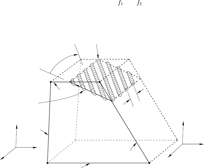
*REBAR
5. Isoparametric direction (for three-dimensional elements only).
In three-dimensional cases the fractional distances ,and are given along the first two edges of
the face identified in Figure 17.10–7 for the isoparametric direction chosen.
Repeat this data line as often as necessary. Each line defines a single rebar.
2
1
3
Positive direction
from lower to
higher numbered
edge.
4
Orientation angle
Rebar
y
x
z
z
r
θ
edge 1
edge 3
edge 4
edge 2
rebar
spacing
Figure 17.10–3 Orientation of rebar in plane and axisymmetric solid elements.
17.10–7
ABAQUS Version 6.1 Module: ID:
Printed on:
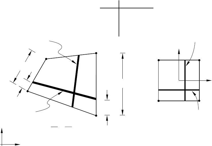
*REBAR
Edge Corner nodes
1 1-2
2 2-3
3 3-4
4 4-1 rebar layer B
LA2
L2
2
1
43
Isoparametric mapping o
f
element with rebar
43
rebar layer A, defined with
edge 1 and f = =
rebar layer B,
defined with
edge 2 or 4
2
1
y
xActual element
rebar layer A
A4
L
2
1
A2
L
L2
A4
L
L4
4
L
Figure 17.10–4 Rebar layer definition in solid elements
with GEOMETRY=ISOPARAMETRIC.
17.10–8
ABAQUS Version 6.1 Module: ID:
Printed on:
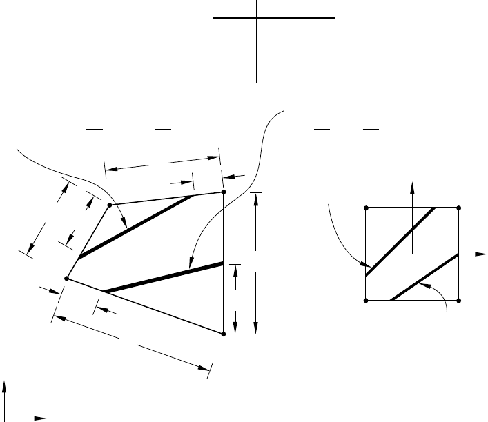
*REBAR
Edge Corner nodes
1 1-2
2 2-3
3 3-4
4 4-1
Isoparametric mapping of
element with rebar
y
x
Actual element
2
1
43
43
2
1
rebar layer
A
A1
L
2
1
L2
LA2
rebar layer A defined with
f1 = , f2 = , f3 = 0 and f4 = 0
A1
L
L1
A2
L
L2
r
ebar layer B defined with
f
1 = 0, f2 = 0, f3 = and f4 =
B3
L
L3
B4
L
L4
3
L
B3
L
4
L
1
L
rebar layer B
B4
L
Figure 17.10–5 Rebar layer definition in solid elements with GEOMETRY=SKEW.
17.10–9
ABAQUS Version 6.1 Module: ID:
Printed on:
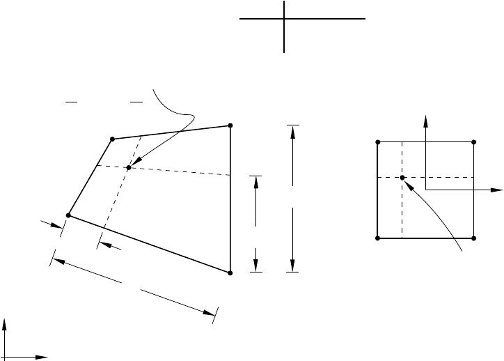
*REBAR
Edge Corner nodes
1 1-2
2 2-3
L2
2
1
43
Isoparametric mapping of
element with rebar
43
2
1
y
x
single reba
r
2
1
Actual element
single rebar defined with
f1 = and f2 =
1
l
L2
2
l
L1
1
l
2
l
1
L
Figure 17.10–6 SINGLE rebar in a solid element.
17.10–10
ABAQUS Version 6.1 Module: ID:
Printed on:
*REBAR
Isoparametric direction: 1 (parallel to the 1-2 edge of the element and intersecting
face 1-4-8-5)
Isoparametric direction: 2 (parallel to the 1-4 edge of the element and intersecting
face 1-5-6-2)
Isoparametric direction: 3 (parallel to the 1-5 edge of the element and intersecting
face 1-2-3-4)
Edge Corner nodes
1 1-4
2 4-8
3 8-5
4 5-1
Edge Corner nodes
1 1-5
2 5-6
3 6-2
4 2-1
Edge Corner nodes
1 1-2
2 2-3
3 3-4
4 4-1
z
y
x
1
8
43
7
5
2
6
8
1
5
7
6
43
2
32
1
⇒
actual element isoparametric mapping
Figure 17.10–7 Isoparametric direction and edge definitions for three-dimensional elements.
17.10–11
ABAQUS Version 6.1 Module: ID:
Printed on:
*REBAR LAYER
17.11 *REBAR LAYER: Define layers of reinforcement in membrane, shell, surface, and
continuum elements.
This option is used to define one or multiple rebar layers in membrane, shell, and surface elements. It must
be used in conjunction with the *MEMBRANE SECTION, the *SHELL SECTION, or the *SURFACE
SECTION option. Rebar layers in solid (continuum) elements can be defined by embedding a set of surface or
membrane elements with rebar layers in a set of host continuum elements through the use of the *EMBEDDED
ELEMENT option.
Products: ABAQUS/Standard ABAQUS/Explicit
Type: Model data
Level: Part, Part instance
References:
•“Defining reinforcement,” Section 2.2.3 of the ABAQUS Analysis User’s Manual
•“Embedded elements,” Section 28.4.1 of the ABAQUS Analysis User’s Manual
•*EMBEDDED ELEMENT
•*MEMBRANE SECTION
•*SHELL SECTION
•*SURFACE SECTION
Optional parameters:
GEOMETRY
Use this parameter to specify the type of rebar geometry.
Set GEOMETRY=CONSTANT (default) if the rebar spacing in the element is constant. The
spacing is given as a length measure on the data lines.
Set GEOMETRY=ANGULAR if the rebar spacing increases linearly as a function of the
distance measured from the axis of revolution in a cylindrical coordinate system. The spacing is
given as an angular spacing in degrees on the data lines. A cylindrical orientation system must be
defined if this option is used with three-dimensional membrane, shell, or surface elements.
Set GEOMETRY=LIFT EQUATION if the rebar spacing and orientation within the element is
determined by the tire “lift” equation. The rebar parameters are defined with respect to the uncured
or “green” tire configuration, and the lift equation maps the rebar parameters to the cured tire
configuration. The spacing is given as a length measure on the data lines. A cylindrical orientation
system must be defined if this option is used with three-dimensional membrane, shell, or surface
elements.
17.11–1
ABAQUS Version 6.1 Module: ID:
Printed on:
*REBAR LAYER
ORIENTATION
This parameter is meaningful only for rebar in general shell, membrane, and surface elements. Set
this parameter equal to the name of an orientation definition that defines the angular orientation of
the rebar on the data lines. If this parameter is omitted, the angular orientation of rebar on the data
lines is specified relative to the default projected local surface directions. This parameter is not
permitted with axisymmetric shell, axisymmetric membrane, and axisymmetric surface elements.
Data lines to define rebar layers:
First line:
1. A name that will be used to identify this rebar layer. This name can be used in defining rebar
prestress and output requests. Each layer of rebar must be given a separate name in a particular
element or element set.
2. Cross-sectional area of the rebar.
3. Spacing of rebar in the plane of the membrane, shell, or surface element. The value is given as
a length measure unless the GEOMETRY=ANGULAR parameter is specified, in which case
the value should be given in terms of angular spacing in degrees. Specify the spacing in the
uncured geometry if GEOMETRY=LIFT EQUATION.
4. Position of the rebar in the shell section thickness direction. This value is given as the distance
of the rebar from the middle surface of the shell, positive in the direction of the positive normal
to the shell. This value is modified if the NODAL THICKNESS parameter is included with
the *SHELL SECTION option for the underlying shell element. This entry has no meaning
for rebar in either membrane or surface elements.
5. Name of the material forming this rebar layer.
6. For three-dimensional shell, membrane, and surface elements, specify the angular orientation
of rebar (in degrees) between the positive local 1-direction and the rebar. Specify the angle in
the uncured geometry if GEOMETRY=LIFT EQUATION.
The local 1-direction can be defined by using the *ORIENTATION option and setting the
ORIENTATION parameter equal to the orientation name. If the ORIENTATION parameter is
omitted, the local 1-direction is defined by the default projected local surface directions. The
optional ORIENTATION parameter given on the *MEMBRANE SECTION and the *SHELL
SECTION options has no influence on the rebar angular orientation.
For axisymmetric shell, axisymmetric membrane, and axisymmetric surface elements, specify
the angular orientation of rebar from the meridional plane in degrees (0° is meridional, 90°
is circumferential). Positive rotation is about the positive normal to the shell, membrane, or
surface elements.
7. The isoparametric direction from which the rebar angle output will be measured. The default
is 1.
8. Extension ratio, e, for rebar defined with GEOMETRY=LIFT EQUATION. This entry has no
meaning for rebar defined using GEOMETRY=CONSTANT or GEOMETRY=ANGULAR.
17.11–2
ABAQUS Version 6.1 Module: ID:
Printed on:

*REBAR LAYER
9. Radius, , of the rebar defined with GEOMETRY=LIFT EQUATION. The value is the
position of the rebar in the uncured geometry, measured with respect to the axis of rotation
in a cylindrical coordinate system. This entry has no meaning for rebar defined using
GEOMETRY=CONSTANT or GEOMETRY=ANGULAR.
Repeat the data line as often as necessary. Each data line defines a layer of rebar.
17.11–3
ABAQUS Version 6.1 Module: ID:
Printed on:
*REFLECTION
17.12 *REFLECTION: Define reflection symmetries for a cavity radiation heat transfer
analysis.
This option is used to define a cavity symmetry by reflection through a line or a plane. It can be used only
following the *RADIATION SYMMETRY option.
Product: ABAQUS/Standard
Type: History data
Level: Step
References:
•“Cavity radiation,” Section 32.1.1 of the ABAQUS Analysis User’s Manual
•*RADIATION SYMMETRY
Required parameter:
TYPE
Set TYPE=LINE to create a cavity composed of the cavity surface defined in the model and its
reflection through a line. See Figure 17.12–1. This option can be used only for two-dimensional
cases.
Set TYPE=PLANE to create a cavity composed of the cavity surface defined in the model
and its reflection through a plane. See Figure 17.12–2. This option can be used only for three-
dimensional cases.
Set TYPE=ZCONST to create a cavity composed by the cavity surface defined in the model
and its reflection through a line of constant z-coordinate. See Figure 17.12–3. This option can be
used only for axisymmetric cases.
Data line to define reflection of a two-dimensional cavity (TYPE=LINE):
First (and only) line:
1. X-coordinate of point a(see Figure 17.12–1).
2. Y-coordinate of point a.
3. X-coordinate of point b.
4. Y-coordinate of point b.
17.12–1
ABAQUS Version 6.1 Module: ID:
Printed on:
*REFLECTION
Data lines to define reflection of a three-dimensional cavity (TYPE=PLANE):
First line:
1. X-coordinate of point a(see Figure 17.12–2).
2. Y-coordinate of point a.
3. Z-coordinate of point a.
4. X-coordinate of point b.
5. Y-coordinate of point b.
6. Z-coordinate of point b.
Second line:
1. X-coordinate of point c.
2. Y-coordinate of point c.
3. Z-coordinate of point c.
Data line to define reflection of an axisymmetric cavity (TYPE=ZCONST):
First (and only) line:
1. z-coordinate of symmetry line (see Figure 17.12–3).
Y
X
a
b
n
Figure 17.12–1 *REFLECTION, TYPE=LINE option.
17.12–2
ABAQUS Version 6.1 Module: ID:
Printed on:
*REFLECTION
Z
X
a
b
n
Y
c
Figure 17.12–2 *REFLECTION, TYPE=PLANE option.
17.12–3
ABAQUS Version 6.1 Module: ID:
Printed on:
*REFLECTION
z
r
z = const
symmetry lin
e
Figure 17.12–3 *REFLECTION, TYPE=ZCONST option.
17.12–4
ABAQUS Version 6.1 Module: ID:
Printed on:
*RELEASE
17.13 *RELEASE: Release rotational degrees of freedom at one or both ends of a beam
element.
This option is used to release a rotational degree of freedom or a combination of rotational degrees of freedom
at one or both ends of a beam element.
Product: ABAQUS/Standard
Type: Model data
Level: Part, Part instance
References:
•“Kinematic coupling constraints,” Section 28.2.3 of the ABAQUS Analysis User’s Manual
•“Element end release,” Section 28.5.1 of the ABAQUS Analysis User’s Manual
Optional parameter:
INPUT
Set this parameter equal to the name of the alternate input file containing the data lines for this
option. See “Input syntax rules,” Section 1.2.1 of the ABAQUS Analysis User’s Manual, for the
syntax of such file names. If this parameter is omitted, it is assumed that the data follow the keyword
line.
Data lines to prescribe the released degrees of freedom:
First line:
1. Element number or element set label.
2. Element end identifier (S1 or S2).
3. Release combination code at the end of the element (M1, M2, T, M1-M2, M1-T, M2-T, ALLM).
See “Element end release,” Section 28.5.1 of the ABAQUS Analysis User’s Manual, for a
definition of the release combination codes in ABAQUS/Standard. This field can be left blank
if none of the rotational degrees of freedom are released at this end of the element.
Repeat this data line as often as necessary to specify the rotational degrees of freedom to be released
for different elements and element ends.
17.13–1
ABAQUS Version 6.1 Module: ID:
Printed on:
*RESPONSE SPECTRUM
17.14 *RESPONSE SPECTRUM: Calculate the response based on user-supplied response
spectra.
This option is used to calculate estimates of peak values of displacements and stresses based on user-supplied
response spectra (defined using the *SPECTRUM option) and on the natural modes of the system.
Product: ABAQUS/Standard
Type: History data
Level: Step
References:
•“Response spectrum analysis,” Section 6.3.10 of the ABAQUS Analysis User’s Manual
•*SPECTRUM
Optional parameters:
COMP
Set COMP=ALGEBRAIC to sum the directional excitation components algebraically. If this
parameter is used, the directional excitation components are summed first, followed by the modal
summation.
Set COMP=SRSS (default) to use the square root of the sum of the squares. If this parameter
is used, the modal summation is performed first, followed by the summation of the directional
excitation components.
SUM
Set SUM=ABS (default) to sum the absolute values of the responses in each natural mode.
Set SUM=CQC to use the complete quadratic combination method to sum the responses in
each natural mode.
Set SUM=NRL to use the Naval Research Laboratory method.
Set SUM=SRSS to use the square root of the sum of squares summation.
Set SUM=TENP to use the Ten Percent Method.
Data lines for a response spectrum analysis:
First line:
1. Name of the response spectrum to be used.
2. X-direction cosine of this direction.
3. Y-direction cosine of this direction.
17.14–1
ABAQUS Version 6.1 Module: ID:
Printed on:
*RESPONSE SPECTRUM
4. Z-direction cosine of this direction.
5. Factor multiplying the magnitudes in the response spectrum. Default is 1.0.
Second line (optional):
1. Name of the response spectrum to be used in the second direction.
2. X-direction cosine of this direction. This direction must be at a right angle to the direction
defined above.
3. Y-direction cosine of this direction. This direction must be at a right angle to the direction
defined above.
4. Z-direction cosine of this direction. This direction must be at a right angle to the direction
defined above.
5. Factor multiplying the magnitudes in the response spectrum. Default is 1.0.
Third line (optional):
1. Name of the response spectrum to be used in the third direction.
2. X-direction cosine of this direction. This direction must be at right angles to the two directions
defined above.
3. Y-direction cosine of this direction. This direction must be at right angles to the two directions
defined above.
4. Z-direction cosine of this direction. This direction must be at right angles to the two directions
defined above.
5. Factor multiplying the magnitudes in the response spectrum. Default is 1.0.
17.14–2
ABAQUS Version 6.1 Module: ID:
Printed on:

*RESTART
17.15 *RESTART: Save and reuse data and analysis results.
WARNING: This option can create a very large amount of data. The size is estimated by
the analysis input file processor in an ABAQUS/Standard analysis.
This option is used to control the writing and reading of restart data.
Products: ABAQUS/Standard ABAQUS/Explicit
Type: Model or history data
Level: Model, Step
Using *RESTART in an ABAQUS/Standard analysis
Reference:
•“Restarting an analysis,” Section 9.1.1 of the ABAQUS Analysis User’s Manual
At least one of the following parameters is required:
READ
Include this parameter to specify that this analysis is a restart of a previous analysis. The basic
model definition data (elements, materials, nodes) cannot be changed at such a restart. However,
element sets, node sets, and *AMPLITUDE tables can be added, and history data subsequent to that
part of the history already analyzed can be changed.
WRITE
Include this parameter to specify that restart data are to be written during the analysis.
Optional parameters if the READ parameter is used:
END STEP
This parameter specifies that the user wishes to terminate the current step in the analysis from which
the restart is being made.
This parameter is useful when the user wishes to redefine the loading history, output options,
or tolerance controls, etc. If this parameter is included, the data must contain further step definitions
to define how the analysis will continue.
If this parameter is omitted, ABAQUS/Standard will continue the analysis to complete the
current step as it is defined in the run from which the restart is being made.
INC
Set this parameter equal to the increment number within the step specified by the STEP parameter,
after which the analysis will resume.
17.15–1
ABAQUS Version 6.1 Module: ID:
Printed on:
*RESTART
If this parameter is omitted, the restart will begin at the end of the step specified on the STEP
parameter.
ITERATION
If the new analysis is restarted from a previous direct cyclic analysis, set this parameter equal to the
iteration number within the specified step of the direct cyclic analysis after which the analysis will
resume. Since the new analysis can be restarted only from the end of a loading cycle in the previous
direct cyclic analysis, the INC parameter is irrelevant and is ignored if the ITERATION parameter
is specified.
If this parameter is omitted, the restart will begin at the end of the last iteration for the specified
step.
STEP
Set this parameter equal to the step number at which the restart will be made.
If this parameter is omitted, the analysis will restart at the last available step found.
Optional parameters if the WRITE parameter is used:
FREQUENCY
This parameter specifies the increments at which restart information will be written. For example,
FREQUENCY=2 will write restart information at increments 2, 4, 6, etc. For a direct cyclic analysis
this parameter specifies the iteration numbers at which restart information will be written; restart
information will be written only at the end of an iteration. When restart is requested in an analysis,
restart information is always written at the end of a step. Set FREQUENCY=0 to discontinue the
writing of restart data.
The FREQUENCY and NUMBER INTERVAL parameters are mutually exclusive. The
default is FREQUENCY=1.
NUMBER INTERVAL
Set this parameter equal to the number of intervals during the step at which the *RESTART data
are to be written. The value of this parameter must be a positive integer.
The FREQUENCY and NUMBER INTERVAL parameters are mutually exclusive. The
default is FREQUENCY=1.
TIME MARKS
Set TIME MARKS=YES (default) to write results at the exact times dictated by the NUMBER
INTERVAL parameter.
Set TIME MARKS=NO to write the restart at the increment ending immediately after the time
dictated by the NUMBER INTERVAL parameter.
OVERLAY
This parameter specifies that only one increment should be retained per step, thus minimizing the
storage space needed.
17.15–2
ABAQUS Version 6.1 Module: ID:
Printed on:

*RESTART
When the OVERLAY parameter is included, each increment written overlays the previous
increment, if any, written for the same step. If this parameter is omitted, data are retained for every
increment. In either case the last increment of every step is retained.
There are no data lines associated with this option.
Using *RESTART in an ABAQUS/Explicit analysis
Reference:
•“Restarting an analysis,” Section 9.1.1 of the ABAQUS Analysis User’s Manual
At least one of the following parameters is required:
READ
Include this parameter to specify that this analysis is a restart of a previous analysis. The basic
model definition data (elements, materials, nodes) cannot be changed at such a restart. However,
element sets, node sets, and *AMPLITUDE tables can be added, and history data subsequent to that
part of the history already analyzed can be changed.
WRITE
Include this parameter to specify that restart data are to be written during the analysis.
Required parameter if the READ parameter is used:
STEP
Set this parameter equal to the step number at which the restart will be made. If the END STEP and
INTERVAL parameters are omitted, the analysis will resume after the last interval available in this
step.
Optional parameters if the READ parameter is used:
END STEP
Include this parameter to specify that the current step should be terminated at this point. The
INTERVAL parameter is required when this parameter is used.
This parameter is useful when the user wishes to redefine the loading history, contact surface
definitions, etc.
If this parameter is omitted, ABAQUS/Explicit will continue the analysis from the last
available restart interval to complete the current step as it is defined in the run from which the
restart is being made.
INTERVAL
Set this parameter equal to the interval number within the step specified by the STEP parameter
after which the analysis will resume. The END STEP parameter is required when this parameter is
used.
17.15–3
ABAQUS Version 6.1 Module: ID:
Printed on:
*RESTART
Optional parameters if the WRITE parameter is used:
NUMBER INTERVAL
Set this parameter equal to the number of intervals during the step at which the *RESTART data
are to be written. The value of this parameter must be a positive integer. The default is NUMBER
INTERVAL=1.
ABAQUS/Explicit will always write the restart data at the beginning and end of the step. For
example, if NUMBER INTERVAL=10, ABAQUS/Explicit will write 11 restart states, consisting
of the values at the beginning of the step and the values at 10 evenly spaced intervals throughout
the step.
TIME MARKS
Set TIME MARKS=NO (default) to write the restart at the increment ending immediately after the
time dictated by the NUMBER INTERVAL parameter.
Set TIME MARKS=YES to write results at the exact times dictated by the NUMBER
INTERVAL parameter. TIME MARKS=YES cannot be used when either the FIXED TIME
INCREMENTATION or DIRECT USER CONTROL parameter is included on the *DYNAMIC
option (“Explicit dynamic analysis,” Section 6.3.3 of the ABAQUS Analysis User’s Manual).
OVERLAY
This parameter specifies that only one increment should be retained per step, thus minimizing the
storage space needed.
When the OVERLAY parameter is included, each increment written overlays the previous
increment, if any, written for the same step. If this parameter is omitted, every increment is retained.
In either case the last increment of every step is retained.
There are no data lines associated with this option.
17.15–4
ABAQUS Version 6.1 Module: ID:
Printed on:
*RETAINED EIGENMODES
17.16 *RETAINED EIGENMODES: Select the modes to be retained in a substructure
generation analysis.
This option selects the modes to be used in a substructure generation analysis. The modes must be extracted
in a prior *FREQUENCY step and will include residual modes if they were activated. If this option is not
used, no modes will be used.
Product: ABAQUS/Standard
Type: History data
Level: Step
Reference:
•“Defining substructures,” Section 10.1.2 of the ABAQUS Analysis User’s Manual
Optional parameter:
GENERATE
If this parameter is included, each data line should give a first mode, ; a last mode; ;andthe
increment in mode numbers between these modes, i. Then, all modes going from to in steps
of iwill be added to the set. imust be an integer such that is a whole number (not a
fraction).
Data lines if the GENERATE parameter is omitted:
First line:
1. List of modes to be used.
Repeat this data line as often as necessary. Up to 16 entries are allowed per line.
Data lines if the GENERATE parameter is included:
First line:
1. First mode number.
2. Last mode number.
3. Increment in mode numbers between modes. The default is 1.
Repeat this data line as often as necessary.
17.16–1
ABAQUS Version 6.1 Module: ID:
Printed on:
*RETAINED NODAL DOFS
17.17 *RETAINED NODAL DOFS: Specify the degrees of freedom that are to be retained as
external to a substructure.
This option is used to list degrees of freedom that are to be retained as external degrees of freedom on the
substructure. It can be used only in a *SUBSTRUCTURE GENERATE analysis.
Product: ABAQUS/Standard
Type: History data
Level: Step
Reference:
•“Defining substructures,” Section 10.1.2 of the ABAQUS Analysis User’s Manual
Optional parameter:
SORTED
Set SORTED=NO to prevent the retained nodes from being sorted. The ordering of the nodes when
using a substructure is then the same as the ordering used when specifying the retained nodes. The
default is SORTED=YES, the retained nodes are sorted into ascending numerical order.
Data lines to define the retained degrees of freedom:
First line:
1. Node number or node set label.
2. First degree of freedom to be retained.
3. Last degree of freedom to be retained.
If only the node number or node set label is given, all degrees of freedom will be retained.
Repeat this data line as often as necessary to list all degrees of freedom to be retained.
17.17–1
ABAQUS Version 6.1 Module: ID:
Printed on:
*RIGID BODY
17.18 *RIGID BODY: Define a set of elements as a rigid body and define rigid element
properties.
This option is used to bind a set of elements and/or a set of nodes and/or an analytical surface into a rigid
body and assign a reference node to the rigid body, which can optionally be declared as an isothermal rigid
body for fully coupled thermal-stress analysis. It is also used to specify density, thickness, and offset for rigid
elements that are part of a rigid body in an ABAQUS/Explicit analysis.
Products: ABAQUS/Standard ABAQUS/Explicit
Type: Model data
Level: Part, Part instance, Assembly
References:
•“Rigid elements,” Section 24.3.1 of the ABAQUS Analysis User’s Manual
•“Defining analytical rigid surfaces,” Section 2.3.4 of the ABAQUS Analysis User’s Manual
•“Rigid body definition,” Section 2.4.1 of the ABAQUS Analysis User’s Manual
Required parameter:
REF NODE
Set this parameter equal to either the node number of the rigid body reference node or the name of
a node set containing the rigid body reference node. If the name of a node set is chosen, the node
set must contain exactly one node.
Optional parameters:
ANALYTICAL SURFACE
Set this parameter equal to the name of the analytical surface to be assigned to the rigid body.
ELSET
Set this parameter equal to the name of the element set containing the elements to be assigned to
the rigid body. An element cannot appear in more than one rigid body.
ISOTHERMAL
This parameter is used only for fully coupled thermal-stress analysis.
Set this parameter equal to YES to specify an isothermal rigid body. The default is
ISOTHERMAL=NO.
17.18–1
ABAQUS Version 6.1 Module: ID:
Printed on:
*RIGID BODY
PIN NSET
Set this parameter equal to the name of a node set containing pin-type nodes to be assigned to the
rigid body. This parameter can be used to add nodes to a rigid body or to redefine node types of
nodes on elements included in the rigid body by the ELSET parameter. Pin-type nodes have only
their translational degrees of freedom associated with the rigid body. A node cannot appear in more
than one rigid body definition.
POSITION
Set POSITION=INPUT (default) if the location of the reference node is to be defined by the user.
Set POSITION=CENTER OF MASS if the reference node is to be located at the center of mass
of the rigid body.
TIE NSET
Set this parameter equal to the name of a node set containing tie-type nodes to be assigned to the
rigid body. This parameter can be used to add nodes to a rigid body or to redefine node types of
nodes on elements included in the rigid body by the ELSET parameter. Tie-type nodes have both
their translational and rotational degrees of freedom associated with the rigid body. A node cannot
appear in more than one rigid body definition.
Optional parameters (use only when the element set specified contains rigid elements):
DENSITY
This parameter applies only to ABAQUS/Explicit analyses.
Set this parameter equal to the density of all of the rigid elements in the element set.
NODAL THICKNESS
This parameter applies only to ABAQUS/Explicit analyses.
Include this parameter to indicate that the thickness of the rigid elements should not be read
from the data line but should be interpolated from the thickness specified at the nodes with the
*NODAL THICKNESS option.
OFFSET
This parameter applies only to ABAQUS/Explicit analyses.
Include this parameter to define the distance (as a fraction of the rigid element’s thickness) from
the element’s midsurface to the reference surface containing the element’s nodes. Since no element
level calculations are performed for rigid elements, a specified offset affects only the handling of
contact pairs with rigid surfaces formed by rigid elements.
This parameter accepts positive or negative values or the labels SPOS or SNEG. The positive
values of the offset are in the direction of the element normal. When OFFSET=0.5 (or SPOS),
the top surface of the rigid element is the reference surface. When OFFSET=−0.5 (or SNEG),
the bottom surface of the rigid element is the reference surface. The default is OFFSET=0, which
indicates that the middle surface of the rigid element is the reference surface.
17.18–2
ABAQUS Version 6.1 Module: ID:
Printed on:
*RIGID BODY
There are no data lines associated with this option in an ABAQUS/Standard analysis.
Data line for R2D2, RB2D2, and RB3D2 elements in an ABAQUS/Explicit analysis:
First (and only) line:
1. Cross-sectional area of the element. The default is 0.
Data line for RAX2, R3D3, and R3D4 elements in an ABAQUS/Explicit analysis:
First (and only) line:
1. Thickness of the element. The default is 0.
17.18–3
ABAQUS Version 6.1 Module: ID:
Printed on:

*RIGID SURFACE
17.19 *RIGID SURFACE: Define an analytical rigid surface.
This option must be used when defining the seabed for three-dimensional drag chain elements in
ABAQUS/Standard analyses. For all other cases the preferred options for defining analytical rigid surfaces
are the *SURFACE and the *RIGID BODY options.
Product: ABAQUS/Standard
Type: Model data
Level: Part, Part instance
References:
•“Surfaces: overview,” Section 2.3.1 of the ABAQUS Analysis User’s Manual
•“Defining analytical rigid surfaces,” Section 2.3.4 of the ABAQUS Analysis User’s Manual
•“Drag chains,” Section 26.12.1 of the ABAQUS Analysis User’s Manual
•“RSURFU,” Section 1.1.15 of the ABAQUS User Subroutines Reference Manual
•*SURFACE
Required parameters:
ELSET
Set this parameter equal to the name of the element set containing the IRS-type elements or the
three-dimensional drag chain elements that may interact with the rigid surface being defined.
The ELSET and NAME parameters are mutually exclusive.
NAME
Set this parameter equal to a label that will be used to refer to the rigid surface being created. This
surface name is used to define contact interaction with another surface through the *CONTACT
PAIR option.
The ELSET and NAME parameters are mutually exclusive.
REF NODE
Set this parameter equal to either the node number of the rigid body reference node or the name of
a node set containing the rigid body reference node. If the name of a node set is chosen, the node
set must contain exactly one node.
This parameter is relevant only when the NAME parameter is used.
TYPE
Set TYPE=SEGMENTS to create a two-dimensional rigid surface in the plane for planar
models or in the plane for axisymmetric models by defining connected line segments.
17.19–1
ABAQUS Version 6.1 Module: ID:
Printed on:
*RIGID SURFACE
Set TYPE=CYLINDER to define a three-dimensional rigid surface by providing connected
line segments and then sweeping them along a specified generator vector.
Set TYPE=REVOLUTION to define a three-dimensional rigid surface by providing connected
line segments, which are given in an plane and are rotated about an axis.
Set TYPE=USER to define a rigid surface via user subroutine RSURFU.
Optional parameter:
FILLET RADIUS
This parameter can be used with TYPE=SEGMENTS, TYPE=CYLINDER, or
TYPE=REVOLUTION to define a radius of curvature to smooth discontinuities between adjoining
straight-line segments, adjoining circular-arc segments, and adjoining straight-line and circular-arc
segments. It has no effect on rigid surfaces defined with TYPE=USER.
No data lines are needed for TYPE=USER.
Data lines to define surfaces created with TYPE=SEGMENTS:
First line:
1. The “word” START.
2. Global X-coordinate or r-coordinate of the starting point of the line segments.
3. Global Y-coordinate or z-coordinate of the starting point of the line segments.
Second and subsequent data lines define the various line, circular, and parabolic segments (see
below for their format) that form the profile of the rigid surface.
Data lines to define surfaces created with TYPE=CYLINDER:
First line:
1. Global X-coordinate of point a, the origin of the local system (see Figure 17.19–1).
2. Global Y-coordinate of point a, the origin of the local system.
3. Global Z-coordinate of point a, the origin of the local system.
4. Global X-coordinate of point bon the local x-axis.
5. Global Y-coordinate of point bon the local x-axis.
6. Global Z-coordinate of point bon the local x-axis.
Second line:
1. Global X-coordinate of point con the local cylinder generator vector.
2. Global Y-coordinate of point con the local cylinder generator vector.
3. Global Z-coordinate of point con the local cylinder generator vector.
17.19–2
ABAQUS Version 6.1 Module: ID:
Printed on:

*RIGID SURFACE
Third line:
1. The “word” START.
2. Local x-coordinate of the starting point of the line segments.
3. Local y-coordinate of the starting point of the line segments.
Fourth and subsequent data lines define the various line, circular, and parabolic segments (see below
for their format) that form the profile of the rigid surface.
Data lines to define surfaces created with TYPE=REVOLUTION:
First line:
1. Global X-coordinate of point a, the origin of the local system (see Figure 17.19–2).
2. Global Y-coordinate of point a, the origin of the local system.
3. Global Z-coordinate of point a, the origin of the local system.
4. Global X-coordinate of point bon the symmetry axis (the local z-axis).
5. Global Y-coordinate of point bon the symmetry axis (the local z-axis).
6. Global Z-coordinate of point bon the symmetry axis (the local z-axis).
Second line:
1. The “word” START.
2. Local r-coordinate of the starting point of the line segments.
3. Local z-coordinate of the starting point of the line segments.
Third and subsequent data lines define the various line, circular, and parabolic segments (see below
for their format) that form the profile of the rigid surface.
Data lines that define the line segments that form the rigid surface for TYPE=SEGMENTS,
TYPE=CYLINDER, and TYPE=REVOLUTION:
Data line to define a straight line segment:
1. The “word” LINE.
2. x-coordinate of the endpoint of the line.
3. y-coordinate of the endpoint of the line.
Data line to define a circular arc segment (the arc must be less than 180°):
1. The “word” CIRCL.
2. x-coordinate of the endpoint of the circular arc.
3. y-coordinate of the endpoint of the circular arc.
4. x-coordinate of the center (origin) of the circular arc.
5. y-coordinate of the center (origin) of the circular arc.
17.19–3
ABAQUS Version 6.1 Module: ID:
Printed on:
*RIGID SURFACE
Data line to define a parabolic arc segment:
1. The “word” PARAB.
2. x-coordinate of the middle point along the parabolic arc.
3. y-coordinate of the middle point along the parabolic arc.
4. x-coordinate of the endpoint of the parabolic arc.
5. y-coordinate of the endpoint of the parabolic arc.
For rigid surfaces created with TYPE=SEGMENTS, the x- and y-coordinates are the global X- and Y-
coordinates or r- and z-coordinates. For rigid surfaces created with TYPE=CYLINDER, the x- and y-
coordinates are the local x- and y-coordinates. For rigid surfaces created with TYPE=REVOLUTION, the
x- and y-coordinates are the local r- and z-coordinates.
S
tart Line segment
Local y-axis
c
Local x-axis
b
a
n
nOutward
normal
Circular arc segment
Local z-axis
Generator
direction
Figure 17.19–1 *RIGID SURFACE, TYPE=CYLINDER.
17.19–4
ABAQUS Version 6.1 Module: ID:
Printed on:
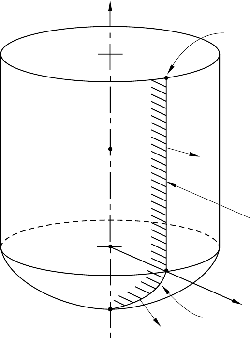
*RIGID SURFACE
local r
line segme
nt
circular arc segment
n
a
b
local z
Start
n
Figure 17.19–2 *RIGID SURFACE, TYPE=REVOLUTION.
17.19–5
ABAQUS Version 6.1 Module: ID:
Printed on:

*ROTARY INERTIA
17.20 *ROTARY INERTIA: Define rigid body rotary inertia.
This option is used to define rigid body rotary inertia values associated with ROTARYI elements.
It is also used in ABAQUS/Standard analyses to define mass proportional damping (for direct-integration
dynamic analysis) and composite damping (for modal dynamic analysis) associated with ROTARYI elements.
Products: ABAQUS/Standard ABAQUS/Explicit
Type: Model data
Level: Part, Part instance, Assembly
Reference:
•“Rotary inertia,” Section 24.2.1 of the ABAQUS Analysis User’s Manual
Required parameter:
ELSET
Set this parameter equal to the name of the element set containing the ROTARYI elements for which
the value is being given.
Optional parameters:
ALPHA
This parameter applies only to ABAQUS/Standard analyses.
Set this parameter equal to the factor to create inertia proportional damping for the
ROTARYI elements when used in direct-integration dynamics. This value is ignored in modal
dynamics. The default is 0.0.
COMPOSITE
This parameter applies only to ABAQUS/Standard analyses.
Set this parameter equal to the fraction of critical damping to be used with the ROTARYI
elements when calculating composite damping factors for the modes when used in modal dynamics.
This value is ignored in direct-integration dynamics. The default is 0.0.
ORIENTATION
Set this parameter equal to the name of an *ORIENTATION option (“Orientations,” Section 2.2.5
of the ABAQUS Analysis User’s Manual) that is being used to define the directions of the local axes
for which the rotary inertia values are being given. If the ORIENTATION parameter is omitted, it
is assumed that the components of the inertia tensor are being given with respect to the global axes;
i.e., the global and local inertia axes coincide.
17.20–1
ABAQUS Version 6.1 Module: ID:
Printed on:
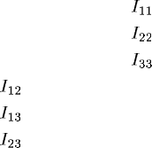
*ROTARY INERTIA
In large-displacement analysis (an ABAQUS/Explicit analysis or when the NLGEOM
parameter is included on the *STEP option in an ABAQUS/Standard analysis), the local axes of
inertia rotate with the rotation of the node to which the ROTARYI element is attached.
Data line to define the rotary inertia:
First (and only) line:
1. Rotary inertia about the local 1-axis, .
2. Rotary inertia about the local 2-axis, .
3. Rotary inertia about the local 3-axis, .
4. Product of inertia, .
5. Product of inertia, .
6. Product of inertia, .
The rotary inertia should be given in units of ML2. ABAQUS does not use any specific physical
units, so the user’s choice must be consistent.
17.20–2
ABAQUS Version 6.1 Module: ID:
Printed on:
S
18. S
ABAQUS Version 6.1 Module: ID:
Printed on:
*SECTION CONTROLS
18.1 *SECTION CONTROLS: Specify section controls.
WARNING: Using values larger than the default values for hourglass control can
produce excessively stiff response and sometimes can even lead to instability if the values
are too large. Hourglassing that occurs with the default hourglass control parameters
is usually an indication that the mesh is too coarse. Therefore, it is generally better to
refine the mesh than to add stronger hourglass control.
This option is used to choose a nondefault hourglass control approach for reduced-integration elements
in ABAQUS/Standard and ABAQUS/Explicit and modified tetrahedral or triangular elements in
ABAQUS/Standard or to scale the default coefficients used in the hourglass control. In ABAQUS/Explicit
it is also used to select a nondefault kinematic formulation for 8-node brick elements, to choose the
second-order accurate formulation for solids and shells, to activate distortion control for solid elements, to
scale the linear and quadratic bulk viscosities, to specify whether elements must be deleted when they are
completely damaged, or to specify a value of the scalar degradation parameter at or above which elements
are assumed to be completely damaged. It is used in conjunction with the *MEMBRANE SECTION,
*SHELL GENERAL SECTION, *SHELL SECTION, and/or *SOLID SECTION options. It can be used
with *BEAM SECTION and *BEAM GENERAL SECTION to scale the linear and bulk viscosities. It can
also be used with the *SOLID SECTION, *SHELL SECTION, *MEMBRANE SECTION, *COHESIVE
SECTION, and *CONNECTOR SECTION options to specify whether elements must be deleted when they
are completely damaged, to specify a value of the scalar degradation parameter at or above which elements
are assumed to be completely damaged, or, in ABAQUS/Standard, to specify the viscosity coefficient that
controls the viscous regularization.
Products: ABAQUS/Standard ABAQUS/Explicit
Type: Model data
Level: Model
References:
•“Section controls,” Section 21.1.4 of the ABAQUS Analysis User’s Manual
•*COHESIVE SECTION
•*CONNECTOR SECTION
•*MEMBRANE SECTION
•*SHELL GENERAL SECTION
•*SHELL SECTION
•*SOLID SECTION
18.1–1
ABAQUS Version 6.1 Module: ID:
Printed on:
*SECTION CONTROLS
Required parameter:
NAME
Set this parameter equal to a label that will be used to refer to the section control definition. All
section control names in the same input file must be unique.
Optional parameters:
DISTORTION CONTROL
This parameter applies only to ABAQUS/Explicit analyses.
Set DISTORTION CONTROL=YES to activate a constraint that acts to prevent negative
element volumes or other excessive distortion for crushable materials. This is the default value
for elements with hyperelastic or hyperfoam materials. The DISTORTION CONTROL parameter
is not relevant for linear kinematics and cannot prevent elements from being distorted due to
temporal instabilities, hourglass instabilities, or physically unrealistic deformation.
Set DISTORTION CONTROL=NO to deactivate a constraint that acts to prevent negative
element volumes or other excessive distortion for crushable materials. This value is the default
except for elements with hyperelastic or hyperfoam materials.
ELEMENT DELETION
In ABAQUS/Explicit this parameter applies to all elements with progressive damage behavior
except connector elements. In ABAQUS/Standard this parameter applies to cohesive elements,
connector elements, and elements with plane stress formulations (plane stress, shell, continuum
shell, and membrane elements).
Set ELEMENT DELETION=YES to allow element deletion when the element has completely
damaged. This value is the default for all elements with a damage evolution model. However, this
value is not applicable to pore pressure cohesive elements.
Set ELEMENT DELETION=NO to allow fully damaged elements to remain in the
computations. The element retains a residual stiffness given by the specified value of MAX
DEGRADATION. In addition, elements with three-dimensional stress states (including
generalized plane strain elements) can sustain hydrostatic compressive stresses, and elements with
one-dimensional stress states can sustain compressive stresses. This value is the default for pore
pressure cohesive elements and is not available for beam elements.
HOURGLASS
Set HOURGLASS=COMBINED to define the viscous-stiffness form of hourglass control for solid
and membrane elements with reduced integration in ABAQUS/Explicit.
Set HOURGLASS=ENHANCED (default for elements with hyperelastic and hyperfoam
materials in ABAQUS/Standard and ABAQUS/Explicit; default in ABAQUS/Standard and only
option in ABAQUS/Explicit for modified tetrahedral or triangular elements) to define hourglass
control that is based on the assumed enhanced strain method for solid, membrane, finite-strain
shell elements with reduced integration and modified tetrahedral or triangular elements in
18.1–2
ABAQUS Version 6.1 Module: ID:
Printed on:
*SECTION CONTROLS
ABAQUS/Standard and ABAQUS/Explicit. Any data given on the data line will be ignored for
this case.
Set HOURGLASS=RELAX STIFFNESS (default for ABAQUS/Explicit, except for elements
with hyperelastic and hyperfoam materials) to use the integral viscoelastic form of hourglass control
for all elements with reduced integration in ABAQUS/Explicit.
Set HOURGLASS=STIFFNESS (default for ABAQUS/Standard, except for elements
with hyperelastic and hyperfoam materials and modified tetrahedral or triangular elements)
to define hourglass control that is strictly elastic for all elements with reduced integration in
ABAQUS/Standard and ABAQUS/Explicit and modified tetrahedral or triangular elements in
ABAQUS/Standard.
Set HOURGLASS=VISCOUS to define the hourglass damping used to control the hourglass
modes for solid and membrane elements with reduced integration in ABAQUS/Explicit.
INITIAL GAP OPENING
This parameter applies only to ABAQUS/Standard analyses using pore pressure cohesive elements.
Set this parameter equal to the value of the initial gap opening used in the tangential flow
continuity equation for pore pressure cohesive elements. The default value is 0.002.
KINEMATIC SPLIT
Include this parameter to change the kinematic formulation for 8-node brick elements only.
Set KINEMATIC SPLIT=AVERAGE STRAIN (default in ABAQUS/Explicit) to use the
uniform strain formulation and the hourglass shape vectors in the hourglass control. This is the
only option available for ABAQUS/Standard.
Set KINEMATIC SPLIT=CENTROID to use the centroid strain formulation and the hourglass
base vectors in the hourglass control in ABAQUS/Explicit.
Set KINEMATIC SPLIT=ORTHOGONAL to use the centroid strain formulation and the
hourglass shape vectors in the hourglass control in ABAQUS/Explicit.
If SECOND ORDER ACCURACY=YES, the KINEMATIC SPLIT parameter will be reset to
AVERAGE STRAIN in ABAQUS/Explicit.
LENGTH RATIO
This parameter applies only to ABAQUS/Explicit analyses and is valid only when the
DISTORTION CONTROL parameter is used.
Set this parameter equal to ( ) to define the length ratio when using distortion
control for crushable materials. The default value is .
MAX DEGRADATION
In ABAQUS/Explicit this parameter applies to all elements with progressive damage behavior
except connector elements. In ABAQUS/Standard this parameter applies to cohesive elements,
connector elements, and elements with plane stress formulations (plane stress, shell, continuum
shell, and membrane elements).
Set this parameter equal to the value of the damage variable at or above which a material point
will be assumed to be completely damaged. This parameter also determines the amount of residual
stiffness that will be retained by elements for which the ELEMENT DELETION parameter is set to
18.1–3
ABAQUS Version 6.1 Module: ID:
Printed on:
*SECTION CONTROLS
NO. For elements other than cohesive elements, connector elements, and elements with plane stress
formulations the default value is 1.0 if the element is deleted from the mesh and 0.99 otherwise.
For cohesive elements, connector elements, and elements with plane stress formulations the default
value is always 1.0.
SECOND ORDER ACCURACY
Set SECOND ORDER ACCURACY=YES to use a second-order accurate formulation for
solid or shell elements suitable for problems undergoing a large number of revolutions (> 5) in
ABAQUS/Explicit. This is the only option available for ABAQUS/Standard.
Set SECOND ORDER ACCURACY=NO (default in ABAQUS/Explicit) to use the first-order
accurate solid or shell elements in ABAQUS/Explicit.
The SECOND ORDER ACCURACY parameter is not relevant for linear kinematics.
VISCOSITY
This parameter applies to cohesive elements, connector elements, and elements with plane stress
formulations (plane stress, shell, continuum shell, and membrane elements) in ABAQUS/Standard
analyses.
Set this parameter equal to the value of the viscosity coefficient used in the viscous
regularization scheme for cohesive elements or connector elements or equal to the value of the
damping coefficient used in connector failure modeling. When this parameter is used to specify
the viscosity coefficients for the damage model for fiber reinforced materials, the specified value is
applied to all the damage modes. The default value is 0.0.
WEIGHT FACTOR
This parameter applies only to ABAQUS/Explicit analyses.
Set this parameter equal to () to scale the contributions from the constant
hourglass stiffness term and the hourglass damping term to the hourglass control formulation.
Setting or corresponds to pure constant stiffness hourglass control and pure
damping hourglass control, respectively. The default is . This option is used only for solid
and membrane elements when the HOURGLASS parameter is set equal to COMBINED.
Data line to define the hourglass control and bulk viscosity:
First (and only) line:
1. Scaling factor, , for the hourglass stiffness, for use with displacement degrees of freedom.
If this value is left blank, ABAQUS will use the default value of 1.0. The suggested range for
the value of is between 0.2 and 3.0.
2. Scaling factor, , for the hourglass stiffness, for use with rotational degrees of freedom in shell
elements. If this value is left blank, ABAQUS will use the default value of 1.0. The suggested
range for the value of is between 0.2 and 3.0.
18.1–4
ABAQUS Version 6.1 Module: ID:
Printed on:

*SECTION CONTROLS
3. Scaling factor, , for the hourglass stiffness for use with the out-of-plane displacement degree
of freedom in small-strain shell elements in ABAQUS/Explicit. If this value is left blank,
ABAQUS/Explicit will use the default value of 1.0. The suggested range for the value of
is between 0.2 and 3.0. This scaling factor is not relevant for ABAQUS/Standard.
4. Scaling factor for the linear bulk viscosity in ABAQUS/Explicit. If this value is left blank,
ABAQUS/Explicit will use the default value of 1.0. The suggested range for the value is
between 0.0 and 1.0. This scaling factor is not relevant for ABAQUS/Standard.
5. Scaling factor for the quadratic bulk viscosity in ABAQUS/Explicit. If this value is left blank,
ABAQUS/Explicit will use the default value of 1.0. The suggested range for the value is
between 0.0 and 1.0. This scaling factor is not relevant for ABAQUS/Standard.
18.1–5
ABAQUS Version 6.1 Module: ID:
Printed on:
*SECTION FILE
18.2 *SECTION FILE: Define results file requests of accumulated quantities on
user-defined surface sections.
This option is used to control output to the results file of accumulated quantities associated with a user-defined
section. Depending on the analysis type the output may include one or several of the following: the total force,
the total moment, the total heat flux, the total current, the total mass flow, or the total pore fluid volume flux
associated with the section.
Product: ABAQUS/Standard
Type: History data
Level: Step
References:
•“Output to the data and results files,” Section 4.1.2 of the ABAQUS Analysis User’s Manual
•“ABAQUS/Standard output variable identifiers,” Section 4.2.1 of the ABAQUS Analysis User’s Manual
Required parameters:
NAME
Set this parameter equal to a label that will be used to identify the output for the section. Section
names in the same input file must be unique.
SURFACE
Set this parameter equal to the name used in the *SURFACE option to define the surface.
Optional parameters:
AXES
Set AXES=LOCAL if output is desired in the local coordinate system. Set AXES=GLOBAL
(default) to output quantities in the global coordinate system.
FREQUENCY
Set this parameter equal to the output frequency, in increments. The output will always be printed
at the last increment of each step unless FREQUENCY=0. The default is FREQUENCY=1. Set
FREQUENCY=0 to suppress the output.
UPDATE
Set UPDATE=NO if output is desired in the original local system of coordinates. Set
UPDATE=YES (default) to output quantities in a local system of coordinates that rotates with the
18.2–1
ABAQUS Version 6.1 Module: ID:
Printed on:
*SECTION FILE
average rigid body motion of the surface section. This parameter is relevant only if AXES=LOCAL
and the NLGEOM parameter is active in the step.
Optional data lines:
First line:
1. Node number of the anchor point (blank if coordinates given).
2. First coordinate of the anchor point (ignored if node number given).
3. Second coordinate of the anchor point (ignored if node number given).
4. Third coordinate of the anchor point (for three-dimensional cases only; ignored if node number
given).
Leave this line blank to allow ABAQUS to define the anchor point.
Second line:
1. Node number used to specify point ain Figure 18.2–1 (blank if coordinates given).
2. First coordinate of point a(ignored if node number given).
3. Second coordinate of point a(ignored if node number given).
The remaining data items are relevant only for three-dimensional cases.
4. Third coordinate of point a(ignored if node number given).
5. Node number used to specify point b(blank if coordinates given).
6. First coordinate of point b(ignored if node number given).
7. Second coordinate of point b(ignored if node number given).
8. Third coordinate of point b(ignored if node number given).
Leave this line blank to allow ABAQUS to define the axes.
Third line:
1. Give the identifying keys for the variables to be output. The keys are defined in the “Section
variables” section of “ABAQUS/Standard output variable identifiers,” Section 4.2.1 of the
ABAQUS Analysis User’s Manual.
Omit both the first and second data lines for AXES=GLOBAL or to allow ABAQUS to define the anchor
point and the axes for AXES=LOCAL. Repeat the third data line as often as necessary to define the
variables to be written to the results file. If this line is omitted, all appropriate variables (“Output to the
data and results files,” Section 4.1.2 of the ABAQUS Analysis User’s Manual) will be output.
18.2–2
ABAQUS Version 6.1 Module: ID:
Printed on:

*SECTION FILE
2
a
3b
1
defined section
2
a
1
anchor point
anchor point
Y
Y
XX
elements used to
define the section
2-D and axisymmetric 3-D
defined section
Z
Figure 18.2–1 User-defined local coordinate system.
18.2–3
ABAQUS Version 6.1 Module: ID:
Printed on:
*SECTION ORIGIN
18.3 *SECTION ORIGIN: Define a meshed cross-section origin.
This option is used in conjunction with the *BEAM SECTION GENERATE option to define the location of
the beam node on a meshed beam cross-section.
Product: ABAQUS/Standard
Type: History data
Level: Step
References:
•“Meshed beam cross-sections,” Section 10.4.1 of the ABAQUS Analysis User’s Manual
•*BEAM SECTION GENERATE
Optional parameter:
ORIGIN
Set ORIGIN=CENTROID to place the beam node at the section centroid.
Set ORIGIN=SHEAR CENTER to place the beam node at the shear center.
Data line to define the location of the beam node if the ORIGIN parameter is omitted:
First (and only) data line:
1. Global x-coordinate of the beam node. The default is 0.0.
2. Global y-coordinate of the beam node. The default is 0.0.
If this option is not used, the section origin is placed at the origin of the coordinate system on the
meshed cross-section model. If this option is used without the ORIGIN parameter and no data line
is given, the section origin is placed at the centroid.
18.3–1
ABAQUS Version 6.1 Module: ID:
Printed on:

*SECTION POINTS
18.4 *SECTION POINTS: Locate points in the beam section for which stress and strain
output are required.
This option is used as model data in ABAQUS/Standard and ABAQUS/Explicit in conjunction with the
*BEAM GENERAL SECTION option and as history data in ABAQUS/Standard in conjunction with the
*BEAM SECTION GENERATE option.
When used in conjunction with the *BEAM GENERAL SECTION option and a predefined library
section, it locates section points in the beam section for which axial stress and axial strain output are required.
When used in conjunction with the *BEAM GENERAL SECTION, SECTION=MESHED option, it
locates elements and integration points in the beam cross-section model for which stress and strain output are
required and provides material data and derivatives of the warping function required for determining stress
and strain output.
When used in conjunction with the *BEAM SECTION GENERATE option, it associates a user-defined
section point label with elements and integration points in the beam cross-section model for which stress and
strain output are required during the subsequent beam analysis.
Products: ABAQUS/Standard ABAQUS/Explicit
Type: Model or history data
Level: Part, Part instance, Step
References:
•“Using a general beam section to define the section behavior,” Section 23.3.7 of the ABAQUS Analysis
User’s Manual
•“Meshed beam cross-sections,” Section 10.4.1 of the ABAQUS Analysis User’s Manual
•*BEAM GENERAL SECTION
There are no parameters associated with this option.
Data lines to locate section points for output when used in conjunction with the *BEAM
GENERAL SECTION option and a predefined library section:
First line:
1. Local -position of first section point.
2. Local -position of first section point.
3. Local -position of second section point.
18.4–1
ABAQUS Version 6.1 Module: ID:
Printed on:
*SECTION POINTS
4. Local -position of second section point.
Continue giving coordinate pairs for as many points as needed. At most four pairs of points can
be specified on any data line. If the point (0,0) is specified as the last entry on a line, it will be ignored
unless it is the only point requested.
Data lines to locate elements and integration point numbers for meshed sections when used in
conjunction with the *BEAM GENERAL SECTION, SECTION=MESHED option:
First line:
1. Section point label.
2. Two-dimensional model element number.
3. Integration point number.
Second line:
1. Young’s modulus, E.
2. Shear modulus in user-defined 1-direction, .
3. Shear modulus in user-defined 2-direction, (for isotropic materials = ).
4. Material orientation angle, , measured counterclockwise from the beam local 1-direction.
5. Local -position of the integration point with respect to the centroid.
6. Local -position of the integration point with respect to the centroid.
7. Derivative of the warping function with respect to the local 1-direction
and the shear center.
8. Derivative of the warping function with respect to the local 2-direction
and the shear center.
Repeat this set of data lines for as many integration points as needed.
Data lines to locate elements and integration point numbers in the cross-section model when
used in conjunction with the *BEAM SECTION GENERATE option:
First line:
1. Section point label.
2. Element number.
3. Integration point number.
Repeat this data line as often as necessary to specify the elements and integration points.
18.4–2
ABAQUS Version 6.1 Module: ID:
Printed on:
*SECTION PRINT
18.5 *SECTION PRINT: Define print requests of accumulated quantities on user-defined
surface sections.
This option is used to provide tabular output of accumulated quantities associated with a user-defined section.
Depending on the analysis type the output may include one or several of the following: the total force, the
total moment, the total heat flux, the total current, the total mass flow, or the total pore fluid volume flux
associated with the section.
Product: ABAQUS/Standard
Type: History data
Level: Step
References:
•“Output to the data and results files,” Section 4.1.2 of the ABAQUS Analysis User’s Manual
•“ABAQUS/Standard output variable identifiers,” Section 4.2.1 of the ABAQUS Analysis User’s Manual
Required parameters:
NAME
Set this parameter equal to a label that will be used to identify the output for the section. Section
names in the same input file must be unique.
SURFACE
Set this parameter equal to the name used in the *SURFACE option to define the surface.
Optional parameters:
AXES
Set AXES=LOCAL if output is desired in the local coordinate system. Set AXES=GLOBAL
(default) to output quantities in the global coordinate system.
FREQUENCY
Set this parameter equal to the output frequency, in increments. The output will always be printed
at the last increment of each step unless FREQUENCY=0. The default is FREQUENCY=1. Set
FREQUENCY=0 to suppress the output.
UPDATE
Set UPDATE=NO if output is desired in the original local system of coordinates. Set
UPDATE=YES (default) to output quantities in a local system of coordinates that rotates with the
18.5–1
ABAQUS Version 6.1 Module: ID:
Printed on:
*SECTION PRINT
average rigid body motion of the surface section. This parameter is relevant only if AXES=LOCAL
and the NLGEOM parameter is active in the step.
Optional data lines:
First line:
1. Node number of the anchor point (blank if coordinates given).
2. First coordinate of the anchor point (ignored if node number given).
3. Second coordinate of the anchor point (ignored if node number given).
4. Third coordinate of the anchor point (for three-dimensional cases only; ignored if node number
given).
Leave this line blank to allow ABAQUS to define the anchor point.
Second line:
1. Node number used to specify point ain Figure 18.5–1 (blank if coordinates given).
2. First coordinate of point a(ignored if node number given).
3. Second coordinate of point a(ignored if node number given).
The remaining data items are relevant only for three-dimensional cases.
4. Third coordinate of point a(ignored if node number given).
5. Node number used to specify point b(blank if coordinates given)
6. First coordinate of point b(ignored if node number given).
7. Second coordinate of point b(ignored if node number given).
8. Third coordinate of point b(ignored if node number given).
Leave this line blank to allow ABAQUS to define the axes.
Third line:
1. Give the identifying keys for the variables to be output. The keys are defined in the “Section
variables” section of “ABAQUS/Standard output variable identifiers,” Section 4.2.1 of the
ABAQUS Analysis User’s Manual.
Omit both the first and second data lines for AXES=GLOBAL or to allow ABAQUS to define the anchor
point and the axes for AXES=LOCAL. Repeat the third data line as often as necessary: each line defines
a table. If this line is omitted, all appropriate variables (“Output to the data and results files,” Section 4.1.2
of the ABAQUS Analysis User’s Manual) will be output.
18.5–2
ABAQUS Version 6.1 Module: ID:
Printed on:
*SECTION PRINT
2
a
3b
1
defined section
2
a
1
anchor point
anchor point
Y
Y
XX
elements used to
define the section
2-D and axisymmetric 3-D
defined section
Z
Figure 18.5–1 User-defined local coordinate system.
18.5–3
ABAQUS Version 6.1 Module: ID:
Printed on:
*SELECT CYCLIC SYMMETRY MODES
18.6 *SELECT CYCLIC SYMMETRY MODES: Specify the cyclic symmetry modes in an
eigenvalue analysis of a cyclic symmetric structure.
This option is used to specify which cyclic symmetry modes should be used in an eigenvalue analysis.
Product: ABAQUS/Standard
Type: History data
Level: Step
References:
•“Analysis of models that exhibit cyclic symmetry,” Section 10.3.3 of the ABAQUS Analysis User’s
Manual
•*CYCLIC SYMMETRY MODEL
•*TIE
Optional parameters:
EVEN
Include this parameter to request the even cyclic symmetry modes only. If this parameter is omitted,
all cyclic symmetry modes will be used within the NMIN, NMAX range.
NMIN
Set this parameter equal to the lowest cyclic symmetry mode number. The default value is 0.
NMAX
Set this parameter equal to the highest cyclic symmetry mode number. The default value is the
highest number that is feasible for the number of sectors given in the *CYCLIC SYMMETRY
MODEL option.
There are no data lines associated with this option.
18.6–1
ABAQUS Version 6.1 Module: ID:
Printed on:
*SELECT EIGENMODES
18.7 *SELECT EIGENMODES: Select the modes to be used in a modal dynamic analysis.
This option selects the modes to be used in a dynamic analysis based on modes or in a complex eigenvalue
extraction analysis. Only one option per step can be used. If this option is not used, all modes extracted in
the prior *FREQUENCY step will be used, including residual modes if they were activated.
Product: ABAQUS/Standard
Type: History data
Level: Step
References:
•“Implicit dynamic analysis using direct integration,” Section 6.3.2 of the ABAQUS Analysis User’s
Manual
•“Complex eigenvalue extraction,” Section 6.3.6 of the ABAQUS Analysis User’s Manual
•“Transient modal dynamic analysis,” Section 6.3.7 of the ABAQUS Analysis User’s Manual
•“Mode-based steady-state dynamic analysis,” Section 6.3.8 of the ABAQUS Analysis User’s Manual
•“Subspace-based steady-state dynamic analysis,” Section 6.3.9 of the ABAQUS Analysis User’s Manual
•“Response spectrum analysis,” Section 6.3.10 of the ABAQUS Analysis User’s Manual
•“Random response analysis,” Section 6.3.11 of the ABAQUS Analysis User’s Manual
•*MODAL DAMPING
Optional parameters:
GENERATE
If this parameter is included, each data line should give a first mode, ; a last mode, ;andthe
increment in mode numbers between these modes, i. Then all modes going from to in steps
of iwill be added to the set. imust be an integer such that is a whole number (not a
fraction).
This parameter can be used only with DEFINITION=MODE NUMBERS.
DEFINITION
Set DEFINITION=MODE NUMBERS (default) to indicate that the selected modes are given as a
collection of mode numbers.
Set DEFINITION= FREQUENCY RANGE to indicate that the modes are selected from the
specified frequency ranges including frequency boundaries. Frequency ranges can be discontinuous.
If both the *MODAL DAMPING and *SELECT EIGENMODES options are used in the same
step, the DEFINITION parameter must be set equal to the same value in both options.
18.7–1
ABAQUS Version 6.1 Module: ID:
Printed on:
*SELECT EIGENMODES
Data lines if the GENERATE parameter is omitted and DEFINITION=MODE NUMBERS:
First line:
1. List of modes to be used.
Repeat this data line as often as necessary. Up to 16 entries are allowed per line.
Data lines if the GENERATE parameter is omitted and DEFINITION=FREQUENCY RANGE:
First line:
1. Lower boundary of the frequency range (in cycles/time).
2. Upper boundary of the frequency range (in cycles/time).
Repeat this data line as often as necessary.
Data lines if the GENERATE parameter is included:
First line:
1. First mode number.
2. Last mode number.
3. Increment in mode numbers between modes. The default is 1.
Repeat this data line as often as necessary.
18.7–2
ABAQUS Version 6.1 Module: ID:
Printed on:

*SFILM
18.8 *SFILM: Define film coefficients and associated sink temperatures over a surface for
heat transfer analysis.
This option is used to provide film coefficients and sink temperatures over a surface for fully coupled thermal-
stress analysis. In ABAQUS/Standard it is also used in heat transfer and coupled thermal-electrical analyses.
Products: ABAQUS/Standard ABAQUS/Explicit
Type: History data
Level: Step
References:
•“Thermal loads,” Section 27.4.4 of the ABAQUS Analysis User’s Manual
•“FILM,” Section 1.1.6 of the ABAQUS User Subroutines Reference Manual
Optional parameters:
AMPLITUDE
Set this parameter equal to the name of the *AMPLITUDE option that gives the variation of the
sink temperature, , with time.
If this parameter is omitted in an ABAQUS/Standard analysis, the reference sink temperature
is applied immediately at the beginning of the step or linearly over the step, depending on the
value assigned to the AMPLITUDE parameter on the *STEP option (“Procedures: overview,”
Section 6.1.1 of the ABAQUS Analysis User’s Manual). If this parameter is omitted in an
ABAQUS/Explicit analysis, the reference sink temperature is applied immediately at the beginning
of the step.
For nonuniform films of type FNU (which are available only in ABAQUS/Standard), the
sink temperature amplitude is defined in user subroutine FILM, and AMPLITUDE references are
ignored.
FILM AMPLITUDE
Set this parameter equal to the name of the *AMPLITUDE option that gives the variation of the
film coefficient, h,withtime.
If this parameter is omitted in an ABAQUS/Standard analysis, the reference film coefficient is
applied immediately at the beginning of the step and kept constant over the step, independent of the
value assigned to the AMPLITUDE parameter on the *STEP option. If this parameter is omitted
in an ABAQUS/Explicit analysis, the reference sink temperature given on the data lines is applied
throughout the step.
18.8–1
ABAQUS Version 6.1 Module: ID:
Printed on:
*SFILM
The FILM AMPLITUDE parameter is ignored if a nonuniform film coefficient is defined in
user subroutine FILM or if a film coefficient is defined to be a function of temperature and field
variables using the *FILM PROPERTY option.
OP
Set OP=MOD (default) to modify existing films or to define additional films.
Set OP=NEW if all existing *SFILMs applied to the model should be removed.
Data lines to define sink temperatures and film coefficients:
First line:
1. Surface name.
2. Film type label F or FNU.
3. Reference sink temperature value, . (Units of .) For nonuniform film coefficients the sink
temperature must be defined in user subroutine FILM. If given, this value will be passed into
the user subroutine.
4. Reference film coefficient value, h(units of JT−1 L−2 −1 ), or name of the film property table
defined with the *FILM PROPERTY option. Nonuniform film coefficients must be defined in
user subroutine FILM. If given, this value will be passed into the user subroutine.
Repeat this data line as often as necessary to define film conditions for different surfaces.
18.8–2
ABAQUS Version 6.1 Module: ID:
Printed on:

*SFLOW
18.9 *SFLOW: Define seepage coefficients and associated sink pore pressures normal to
a surface.
This option is used to provide seepage coefficients and sink pore pressures to control pore fluid flow normal
to the surface in consolidation analysis.
Product: ABAQUS/Standard
Type: History data
Level: Step
References:
•“Pore fluid flow,” Section 27.4.6 of the ABAQUS Analysis User’s Manual
•“FLOW,” Section 1.1.7 of the ABAQUS User Subroutines Reference Manual
Optional parameters:
AMPLITUDE
Set this parameter equal to the name of the amplitude curve that gives the variation of reference pore
pressure with time. If this parameter is omitted, the reference magnitude is applied immediately
at the beginning of the step or linearly over the step depending on the value assigned to the
AMPLITUDE parameter on the *STEP option (see “Procedures: overview,” Section 6.1.1 of the
ABAQUS Analysis User’s Manual). The AMPLITUDE parameter is ignored for nonuniform
seepage flow boundary conditions defined in user subroutine FLOW and for drainage-only seepage
boundary conditions.
OP
Set OP=MOD (default) to modify existing flows or to define additional flows.
Set OP=NEW if all existing *SFLOWs applied to the model should be removed. New flows
can be defined.
Data lines to define uniform seepage:
First line:
1. Surface name.
2. Seepage flow type label Q.
3. Reference pore pressure value, . (Units of FL−2 .)
4. Reference seepage coefficient value, . (Units of F−1 L3T−1 .)
Repeat this data line as often as necessary to define uniform seepage for various surfaces.
18.9–1
ABAQUS Version 6.1 Module: ID:
Printed on:
*SFLOW
Data lines to define drainage-only seepage:
First line:
1. Surface name.
2. Seepage flow type label QD.
3. Drainage-only seepage coefficient value, .(UnitsofF
−1 L3T−1 .)
Repeat this data line as often as necessary to define drainage-only seepage for various surfaces.
Data lines to define nonuniform seepage:
First line:
1. Surface name.
2. Seepage flow type label QNU.
3. Optional reference pore pressure value. If given, this value is passed into user subroutine FLOW
in the variable used to define the sink pore pressure.
4. Optional reference seepage coefficient. If given, this value is passed into user subroutine FLOW
in the variable used to define the seepage coefficient.
The reference pore pressure value, , and reference seepage coefficient, , are defined in user
subroutine FLOW for nonuniform flow.
Repeat this data line as often as necessary to define nonuniform seepage for various surfaces.
18.9–2
ABAQUS Version 6.1 Module: ID:
Printed on:
*SHEAR CENTER
18.10 *SHEAR CENTER: Define the position of the shear center of a beam section.
This option can be used only in conjunction with the *BEAM GENERAL SECTION, SECTION=GENERAL
or the *BEAM GENERAL SECTION, SECTION=MESHED option. It is used to define the position of the
shear center of the section with respect to the local (1, 2) axis system.
Products: ABAQUS/Standard ABAQUS/Explicit
Type: Model data
Level: Part, Part instance
References:
•“Using a general beam section to define the section behavior,” Section 23.3.7 of the ABAQUS Analysis
User’s Manual
•*BEAM GENERAL SECTION
•“Meshed beam cross-sections,” Section 10.4.1 of the ABAQUS Analysis User’s Manual
There are no parameters associated with this option.
Data line to define the shear center:
First (and only) line:
1. Local -coordinate of shear center, . The default is 0.
2. Local -coordinate of shear center, . The default is 0.
18.10–1
ABAQUS Version 6.1 Module: ID:
Printed on:
*SHEAR FAILURE
18.11 *SHEAR FAILURE: Specify a shear failure model and criterion.
This option is used with the Mises or the Johnson-Cook plasticity models to specify shear failure of the
material. It must be used in conjunction with the option *PLASTIC, HARDENING=ISOTROPIC or
JOHNSON COOK.
Product: ABAQUS/Explicit
Type: Model data
Level: Model
References:
•“Classical metal plasticity,” Section 18.2.1 of the ABAQUS Analysis User’s Manual
•“Johnson-Cook plasticity,” Section 18.2.7 of the ABAQUS Analysis User’s Manual
•“Dynamic failure models,” Section 18.2.8 of the ABAQUS Analysis User’s Manual
•*PLASTIC
Optional parameters:
DEPENDENCIES
This parameter is relevant only for TYPE=TABULAR.
Set this parameter equal to the number of field variable dependencies included in the definition
of the equivalent plastic strain at failure, in addition to temperature. If this parameter is omitted,
it is assumed that the strain at failure depends on the plastic strain, the plastic strain rate, the
dimensionless pressure-deviatoric stress ratio and, possibly, on temperature. See “Using the
DEPENDENCIES parameter to define field variable dependence” in “Material data definition,”
Section 16.1.2 of the ABAQUS Analysis User’s Manual, for more information.
ELEMENT DELETION
Set ELEMENT DELETION=YES (default) to allow element deletion when the failure criterion is
met.
Set ELEMENT DELETION=NO to allow the element to take hydrostatic compressive stress
only when the failure criterion is met.
TYPE
Set TYPE=JOHNSON COOK to define the Johnson-Cook shear failure criterion. It requires the
use of the *PLASTIC, HARDENING=JOHNSON COOK option.
Set TYPE=TABULAR (default) to define the failure strain in tabular data form. It requires the
use of the *PLASTIC, HARDENING=ISOTROPIC option.
18.11–1
ABAQUS Version 6.1 Module: ID:
Printed on:
*SHEAR FAILURE
Data lines to define the failure strain in tabular form (TYPE=TABULAR):
First line:
1. Equivalent plastic strain at failure, .
2. Rate of equivalent plastic strain, .
3. Dimensionless pressure-deviatoric stress ratio, .
4. Temperature.
5. First field variable.
6. Second field variable.
7. Etc., up to four field variables.
Subsequent lines (only needed if the DEPENDENCIES parameter has a value greater than four):
1. Fifth field variable.
2. Etc., up to eight field variables per line.
Repeat this set of data lines as often as necessary to define the dependence of strain at failure on plastic
strain, plastic strain rate, stress ratio and, if needed, on temperature and other predefined field variables.
Data line to define the Johnson-Cook shear failure criterion (TYPE=JOHNSON COOK):
First (and only) line:
1. Johnson-Cook failure parameter, .
2. Johnson-Cook failure parameter, .
3. Johnson-Cook failure parameter, .
4. Johnson-Cook failure parameter, .
5. Johnson-Cook failure parameter, .
18.11–2
ABAQUS Version 6.1 Module: ID:
Printed on:
*SHEAR RETENTION
18.12 *SHEAR RETENTION: Define the reduction of the shear modulus associated with
crack surfaces in a *CONCRETE model as a function of the tensile strain across the
crack.
This option is used to give a multiplying factor, , that defines the modulus for shearing of cracks as a
fraction of the elastic shear modulus of the uncracked concrete. If this option is used, it should follow
the *CONCRETE option. The *SHEAR RETENTION option can also be used in conjunction with the
*FAILURE RATIOS option.
Product: ABAQUS/Standard
Type: Model data
Level: Model
References:
•“Concrete smeared cracking,” Section 18.5.1 of the ABAQUS Analysis User’s Manual
•*CONCRETE
•*FAILURE RATIOS
Optional parameter:
DEPENDENCIES
Set this parameter equal to the number of field variable dependencies included in the definition
of shear retention behavior, in addition to temperature. If this parameter is omitted, it is assumed
that the shear retention behavior depends only on temperature. See “Specifying field variable
dependence” in “Material data definition,” Section 16.1.2 of the ABAQUS Analysis User’s
Manual, for more information.
Data lines to define the shear retention behavior:
First line:
1. . The default is 1.0.
2. . The default is a very large number (full shear retention).
3. Not used.
4. Not used.
5. Temperature.
6. First field variable.
18.12–1
ABAQUS Version 6.1 Module: ID:
Printed on:
*SHEAR RETENTION
7. Second field variable.
8. Third field variable.
Subsequent lines (only needed if the DEPENDENCIES parameter has a value greater than three):
1. Fourth field variable.
2. Etc., up to eight field variables per line.
Repeat this set of data lines as often as necessary to define the dependence of the shear retention
behavior on temperature and other predefined field variables.
18.12–2
ABAQUS Version 6.1 Module: ID:
Printed on:
*SHEAR TEST DATA
18.13 *SHEAR TEST DATA: Used to provide shear test data.
This option can be used only in conjunction with the *VISCOELASTIC option. The *SHEAR TEST DATA
option cannot be used for a viscoelastic material if the *COMBINED TEST DATA option is used.
Products: ABAQUS/Standard ABAQUS/Explicit
Type: Model data
Level: Model
Using shear test data to define a viscoelastic material
References:
•“Time domain viscoelasticity,” Section 17.7.1 of the ABAQUS Analysis User’s Manual
•*VISCOELASTIC
Optional parameter:
SHRINF
To specify creep test data, set this parameter equal to the value of the long-term, normalized shear
compliance .
To specify relaxation test data, set this parameter equal to the value of the long-term,
normalized shear modulus . The shear compliance and shear modulus are related by
. The fitting procedure will use the specified value in the constraint
.
Data lines to specify creep test data:
First line:
1. Normalized shear compliance .
2. Time t.
Repeat this data line as often as necessary to give the compliance-time data.
Data lines to specify relaxation test data:
First line:
1. Normalized shear relaxation modulus .
2. Time t.
Repeat this data line as often as necessary to give the modulus-time data.
18.13–1
ABAQUS Version 6.1 Module: ID:
Printed on:
*SHELL GENERAL SECTION
18.14 *SHELL GENERAL SECTION: Define a general, arbitrary, elastic shell section.
This option is used to define a general, arbitrary, elastic shell section.
Products: ABAQUS/Standard ABAQUS/Explicit
Type: Model data
Level: Part, Part instance
References:
•“Shell elements: overview,” Section 23.6.1 of the ABAQUS Analysis User’s Manual
•“Using a general shell section to define the section behavior,” Section 23.6.6 of the ABAQUS Analysis
User’s Manual
•“UGENS,” Section 1.1.25 of the ABAQUS User Subroutines Reference Manual
Required parameter:
ELSET
Set this parameter equal to the name of the element set containing the shell elements for which the
section behavior is being defined.
Required parameter in ABAQUS/Explicit, optional parameter in ABAQUS/Standard:
DENSITY
Set this parameter equal to the mass per unit surface area of the shell.
If the MATERIAL and COMPOSITE parameters are omitted, this density accounts for the
mass of the shell, since no material definition is given.
If the MATERIAL or COMPOSITE parameter is used, the mass of the shell includes a
contribution from this parameter in addition to any contribution from the material definition.
Optional parameters:
CONTROLS
In an ABAQUS/Explicit analysis, set this parameter equal to the name of a section controls
definition (see “Section controls,” Section 21.1.4 of the ABAQUS Analysis User’s Manual) to
be used to specify the second-order accurate element formulation option, a nondefault hourglass
control formulation option, or scale factors.
In an ABAQUS/Standard analysis, set this parameter equal to the name of a section
controls definition to be used to specify the enhanced hourglass control formulation (see “Section
18.14–1
ABAQUS Version 6.1 Module: ID:
Printed on:
*SHELL GENERAL SECTION
controls,” Section 21.1.4 of the ABAQUS Analysis User’s Manual) or to be used in a subsequent
ABAQUS/Explicit import analysis.
OFFSET
Include this parameter to define the distance (as a fraction of the shell thickness) from the shell
midsurface to the reference surface (containing the nodes of the element). This parameter accepts
positive or negative values or the labels SPOS or SNEG.
Positive values of the offset are in the positive normal direction (see “Shell elements:
overview,” Section 23.6.1 of the ABAQUS Analysis User’s Manual). When OFFSET=0.5 (or
SPOS), the top surface of the shell is the reference surface. When OFFSET=−0.5 (or SNEG), the
bottom surface of the shell is the reference surface. The default is OFFSET=0, which indicates
that the middle surface of the shell is the reference surface.
This parameter cannot be used if the MATERIAL and COMPOSITE parameters are omitted.
This parameter is ignored for continuum shells.
ORIENTATION
Set this parameter equal to the name of an orientation definition (see “Orientations,” Section 2.2.5
of the ABAQUS Analysis User’s Manual) to be used with the section forces and section strains.
POISSON
Include this parameter to define the shell thickness direction behavior.
Set this parameter equal to a nonzero value to cause the thickness direction strain under plane
stress conditions to be a linear function of the membrane strains. The value of the POISSON
parameter must be between −1.0 and 0.5.
Set POISSON=ELASTIC to automatically select this parameter value based on the initial
isotropic elastic part of the material definition.
The default is POISSON=0.5.
STACK DIRECTION
This parameter is relevant only for continuum shells.
This parameter defines the continuum shell stack or thickness direction. Set this parameter
equal to 1, 2, 3, or ORIENTATION. The default is STACK DIRECTION=3. The ORIENTATION
parameter must also be used if STACK DIRECTION=ORIENTATION.
THICKNESS MODULUS
This parameter is relevant only for continuum shells.
Set this parameter equal to an effective thickness modulus. The default effective thickness
modulus is twice the initial in-plane shear modulus based on the material definition.
ZERO
If the section is defined by its general stiffness, set this parameter equal to , the reference
temperature for thermal expansion (for example, ZERO=50 means ).
This parameter is ignored if the COMPOSITE, the MATERIAL, or the USER parameter is
specified.
18.14–2
ABAQUS Version 6.1 Module: ID:
Printed on:
*SHELL GENERAL SECTION
The following parameters are optional, mutually exclusive, and used only if the section is not
defined by its general stiffness on the data lines:
COMPOSITE
Include this parameter to indicate that the shell is composed of layers with different linear elastic
material behavior.
MATERIAL
Set this parameter equal to the name of the single linear elastic material of which the shell is made.
USER
This parameter applies only to ABAQUS/Standard analyses. See “Using a general shell section to
define the section behavior,” Section 23.6.6 of the ABAQUS Analysis User’s Manual, for use of
this option in linear perturbation analyses.
Include this parameter to indicate that the shell section stiffness is defined in user subroutine
UGENS.
The following optional parameter can be used only in combination with the MATERIAL, the
COMPOSITE, or the USER parameter:
NODAL THICKNESS
Include this parameter to indicate that the shell thickness should not be read from the data lines but
should be interpolated from the thickness specified at the nodes with the *NODAL THICKNESS
option. For composite sections the total thickness is interpolated from the nodes, and the thicknesses
of the layers specified on the data lines are scaled proportionally. This parameter is ignored for
continuum shells.
The following optional parameters can be used only in combination with the USER parameter:
IPROPERTIES
Set this parameter equal to the number of integer property values needed as data in user subroutine
UGENS. The default is I PROPERTIES=0.
PROPERTIES
Set this parameter equal to the number of real (floating point) property values needed as data in user
subroutine UGENS. The default is PROPERTIES=0.
UNSYMM
Include this parameter if the section stiffness matrices are not symmetric. This parameter will invoke
the unsymmetric equation solution capability.
VARIABLES
Set this parameter equal to the number of solution-dependent variables that must be stored for the
section. The default is VARIABLES=1.
18.14–3
ABAQUS Version 6.1 Module: ID:
Printed on:
*SHELL GENERAL SECTION
Optional parameter for use when the MATERIAL, the COMPOSITE, and the USER parameters
are omitted:
DEPENDENCIES
Set this parameter equal to the number of field variable dependencies included in the definition of
the scaling moduli, in addition to temperature. If this parameter is omitted, it is assumed that the
moduli are constant or depend only on temperature.
Data line if the MATERIAL parameter is included:
First (and only) line:
1. Shell thickness. This value is ignored if the NODAL THICKNESS parameter is included.
Data lines if the COMPOSITE parameter is included:
First line:
1. Layer thickness. This value is scaled if the NODAL THICKNESS parameter is included.
2. This field is not used (any value given will be ignored). It is included for compatibility with
the *SHELL SECTION option.
3. Name of the material forming this layer.
4. Orientation angle, , (in degrees) measured positive counterclockwise relative to the
orientation definition given with the ORIENTATION parameter, where .
If the ORIENTATION parameter is not included, is measured relative to the default shell
local directions (see “Conventions,” Section 1.2.2 of the ABAQUS Analysis User’s Manual).
Repeat this data line as often as necessary to define the layers of the shell. The order of the laminated
shell layers with respect to the positive direction of the shell normal is defined by the order of the data
lines.
Data lines to define the shell section if the MATERIAL, the COMPOSITE, and the USER
parameters are omitted:
First line:
1. Symmetric half of the matrix in the order ,,,,,,,..., ,
,..., ,..., ,...,
Repeat this data line three times. Enter 21 entries total, 8 per line.
Second line (optional):
1. vector ( ,, ..., ).
Third line (optional):
1. Y, scaling modulus for . The default is 1.0.
2. , scaling modulus for . The default is 0.0.
18.14–4
ABAQUS Version 6.1 Module: ID:
Printed on:
*SHELL GENERAL SECTION
3. , temperature for these values of Yand .
4. First field variable.
5. Second field variable.
6. Etc.,uptofivefieldvariables.
Subsequent lines (only needed if the DEPENDENCIES parameter has a value greater than five):
1. Sixth field variable.
2. Etc., up to eight field variables per line.
Repeat this set of data lines as often as necessary to define Yand as functions of temperature and
other predefined field variables.
Data lines if the USER parameter is included:
First line:
1. Shell thickness. This value is ignored if the NODAL THICKNESS parameter is included.
Second line:
1. Enter the data to be used as properties in user subroutine UGENS. Enter all floating point values
first, followed immediately by the integer values.
Repeat this data line as often as necessary to define the properties required in UGENS. Enter eight values
per line for both real and integer values.
18.14–5
ABAQUS Version 6.1 Module: ID:
Printed on:
*SHELL SECTION
18.15 *SHELL SECTION: Specify a shell cross-section.
This option is used to specify a shell cross-section.
Products: ABAQUS/Standard ABAQUS/Explicit
Type: Model data
Level: Part, Part instance
References:
•“Shell elements: overview,” Section 23.6.1 of the ABAQUS Analysis User’s Manual
•“Using a shell section integrated during the analysis to define the section behavior,” Section 23.6.5 of
the ABAQUS Analysis User’s Manual
Required parameter:
ELSET
Set this parameter equal to the name of the element set containing the shell elements for which the
section behavior is being defined.
Required, mutually exclusive parameters:
COMPOSITE
Include this parameter if the shell is made up of several layers of material.
MATERIAL
Set this parameter equal to the name of the material of which the shell is made.
Optional parameters:
CONTROLS
In an ABAQUS/Explicit analysis, set this parameter equal to the name of a section controls
definition (see “Section controls,” Section 21.1.4 of the ABAQUS Analysis User’s Manual) to
be used to specify the second-order accurate element formulation option, a nondefault hourglass
control formulation option, or scale factors.
In an ABAQUS/Standard analysis, set this parameter equal to the name of a section
controls definition to be used to specify the enhanced hourglass control formulation (see “Section
controls,” Section 21.1.4 of the ABAQUS Analysis User’s Manual) or to be used in a subsequent
ABAQUS/Explicit import analysis.
18.15–1
ABAQUS Version 6.1 Module: ID:
Printed on:
*SHELL SECTION
DENSITY
Set this parameter equal to a mass per unit surface area of the shell.
If this parameter is used, the mass of the shell includes a contribution from this parameter in
addition to any contribution from the material definition.
NODAL THICKNESS
Include this parameter to indicate that the shell thickness should not be read from the data lines but
should be interpolated from the thickness specified at the nodes with the *NODAL THICKNESS
option. For composite sections the total thickness is interpolated from the nodes and the thicknesses
of the layers specified on the data lines are scaled proportionally. This parameter is ignored for
continuum shells.
OFFSET
Include this parameter to define the distance (as a fraction of the shell thickness) from the shell
midsurface to the reference surface (containing the nodes of the element). This parameter accepts
positive or negative values or the labels SPOS or SNEG.
Positive values of the offset are in the positive normal direction (see “Shell elements:
overview,” Section 23.6.1 of the ABAQUS Analysis User’s Manual). When OFFSET=0.5 (or
SPOS), the top surface of the shell is the reference surface. When OFFSET=−0.5 (or SNEG), the
bottom surface of the shell is the reference surface. The default is OFFSET=0, which indicates that
the middle surface of the shell is the reference surface. This parameter is ignored for continuum
shells.
ORIENTATION
Set this parameter equal to the name of an orientation definition (“Orientations,” Section 2.2.5 of
the ABAQUS Analysis User’s Manual) to be used with material calculations in this definition of
shell section behavior. This orientation will be used for material calculations and stress output in
the individual layers, for the section forces output, and for the transverse shear stiffness.
It is possible to use a different orientation definition for material calculations in the individual
layers of a composite shell by referencing an orientation definition or giving an orientation angle
(in degrees, positive counterclockwise relative to the shell local directions) on each layer definition
data line. Any layer definition line that does not have an orientation reference or an angle specified
will use the orientation defined here.
POISSON
Include this parameter to define the shell thickness direction behavior.
Set this parameter equal to a nonzero value to cause the thickness direction strain under plane
stress conditions to be a linear function of the membrane strains. The value of the POISSON
parameter must be between −1.0 and 0.5.
Set POISSON=ELASTIC to automatically select this parameter value based on the initial
elastic part of the material definition.
Set POISSON=MATERIAL in an ABAQUS/Explicit analysis to cause the thickness direction
strain under plane stress conditions to be a function of the membrane strains and the in-plane material
properties.
18.15–2
ABAQUS Version 6.1 Module: ID:
Printed on:
*SHELL SECTION
In ABAQUS/Standard the default is POISSON=0.5; in ABAQUS/Explicit the default is
POISSON=MATERIAL.
STACK DIRECTION
This parameter is relevant only for continuum shells.
This parameter defines the continuum shell stack or thickness direction. Set this parameter
equal to 1, 2, 3, or ORIENTATION. The default is STACK DIRECTION=3. The ORIENTATION
parameter must also be used if STACK DIRECTION=ORIENTATION.
SECTION INTEGRATION
Set SECTION INTEGRATION=SIMPSON (default) to use Simpson’s rule for the shell section
integration.
Set SECTION INTEGRATION=GAUSS to use Gauss quadrature for the shell section
integration. Gauss quadrature cannot be used for heat transfer or thermally coupled shell elements.
TEMPERATURE
Use this parameter to select the mode of temperature and field variable input used on the *FIELD,
the *INITIAL CONDITIONS, or the *TEMPERATURE options.
Omit the TEMPERATURE parameter to define the predefined field by its magnitude on the
reference surface of the shell and its gradient through the thickness.
Set TEMPERATURE=n,wherenis the number of predefined field variable points in the shell
or in each layer if the COMPOSITE parameter is used, to define the predefined field at nequally
spaced points through each layer of the shell section.
In a heat transfer analysis step or a coupled temperature-displacement analysis step when
the *FIELD option is used to specify values of predefined field variables, the TEMPERATURE
parameter is required to specify the number of field variable points in the shell. The number of
temperature points in the shell with temperature degrees of freedom is defined by the number of
integration points specified on the data lines.
THICKNESS MODULUS
This parameter is relevant only for continuum shells.
Set this parameter equal to an effective thickness modulus. The default effective thickness
modulus is twice the initial in-plane shear modulus based on the material definition.
Data line to define a homogeneous shell (the MATERIAL parameter is included):
First (and only) line:
1. Shell thickness. This value is ignored if the NODAL THICKNESS parameter is included.
2. Number of integration points to be used through the shell section. The default is five points if
Simpson’s rule is used and three points if Gauss quadrature is used. The number of integration
points must be an odd number for Simpson’s rule and, in an ABAQUS/Standard analysis, is
equal to the number of temperature degrees of freedom at a node of the element if this section
is associated with heat transfer or coupled temperature-displacement elements. This number
must be at least 2 and less than or equal to 7 for Gauss quadrature. For Simpson’s rule it must
18.15–3
ABAQUS Version 6.1 Module: ID:
Printed on:
*SHELL SECTION
be at least 3, except in a pure heat transfer analysis, where the number of integration points
can be 1 for a constant temperature through the shell thickness.
Data lines to define a composite shell (the COMPOSITE parameter is included):
First line:
1. Layer thickness. This value is modified if the NODAL THICKNESS parameter is included.
2. Number of integration points to be used through the layer. The default is three points if
Simpson’s rule is used and two points if Gauss quadrature is used. The number of integration
points must be an odd number for Simpson’s rule and, in an ABAQUS/Standard analysis,
determines the number of temperature degrees of freedom at a node of the element if this
section is associated with heat transfer or coupled temperature-displacement elements. This
number must be less than or equal to 7 for Gauss quadrature.
3. Name of the material forming this layer.
4. Name of the orientation to be used with this layer or the orientation angle, , (in degrees)
measured positive counterclockwise relative to the orientation definition given with the
ORIENTATION parameter, where . If the ORIENTATION parameter is
not included, is measured relative to the default shell local directions (see “Orientations,”
Section 2.2.5 of the ABAQUS Analysis User’s Manual).
Repeat this data line as often as necessary. Use one data line for each layer of the shell. The order of
the laminated shell layers with respect to the positive direction of the shell normal is defined by the order
of the data lines.
18.15–4
ABAQUS Version 6.1 Module: ID:
Printed on:
*SHELL TO SOLID COUPLING
18.16 *SHELL TO SOLID COUPLING: Define a surface-based coupling between a shell
edge and a solid face.
This surface-based option allows for a transition from shell element modeling to solid element modeling in a
three-dimensional analysis.
Products: ABAQUS/Standard ABAQUS/Explicit
Type: Model data
Level: Part, Part instance, Assembly
References:
•“Defining element-based surfaces,” Section 2.3.2 of the ABAQUS Analysis User’s Manual
•“Defining node-based surfaces,” Section 2.3.3 of the ABAQUS Analysis User’s Manual
•“Shell-to-solid coupling,” Section 28.3.3 of the ABAQUS Analysis User’s Manual
Required parameter:
CONSTRAINT NAME
Set this parameter equal to a label that will be used to refer to this constraint.
Optional parameters:
INFLUENCE DISTANCE
Set this parameter equal to the perpendicular distance from the edge-based surface within which all
nodes or element facets on the solid surface (depending on the solid surface type) must lie to be
included in the coupling constraint. The default value is half the thickness of the shell that was used
to define the edge-based surface.
POSITION TOLERANCE
Set this parameter equal to the distance within which nodes on the edge-based surface must lie from
the solid surface to be included in the coupling definition. The default tolerance is 5% of the length
of a typical facet on the shell edge.
Data lines to define the surfaces forming the coupling definitions:
First line:
1. The edge-based surface name.
18.16–1
ABAQUS Version 6.1 Module: ID:
Printed on:
*SHELL TO SOLID COUPLING
2. The solid surface name.
Repeat this data line as often as necessary to define all the surfaces forming the coupling definition.
Each data line defines a pair of surfaces that will be coupled.
18.16–2
ABAQUS Version 6.1 Module: ID:
Printed on:
*SIMPEDANCE
18.17 *SIMPEDANCE: Define impedances of acoustic surfaces.
This option is used to provide surface impedance information or nonreflecting boundaries for acoustic and
coupled acoustic-structural analysis.
Products: ABAQUS/Standard ABAQUS/Explicit
Type: History data
Level: Step
References:
•“Acoustic, shock, and coupled acoustic-structural analysis,” Section 6.9.1 of the ABAQUS Analysis
User’s Manual
•“Acoustic loads,” Section 27.4.5 of the ABAQUS Analysis User’s Manual
•*IMPEDANCE
•*IMPEDANCE PROPERTY
Required, mutually exclusive parameters:
PROPERTY
Set this parameter equal to the name of the *IMPEDANCE PROPERTY option defining the table
of impedance values to be used.
NONREFLECTING
Set NONREFLECTING=PLANAR (default) to specify the impedance corresponding to that of a
normal incidence plane wave.
Set NONREFLECTING=IMPROVED to specify the impedance corresponding to that of
a plane wave at an arbitrary angle of incidence. This parameter can be used only for transient
dynamics.
Set NONREFLECTING=CIRCULAR to specify a radiation condition appropriate for a
circular boundary in two dimensions or a right circular cylinder in three dimensions.
Set NONREFLECTING=SPHERICAL to specify a radiation condition appropriate for a
spherical boundary.
Set NONREFLECTING=ELLIPTICAL to specify a radiation condition appropriate for an
elliptical boundary in two dimensions or a right elliptical cylinder in three dimensions.
Set NONREFLECTING=PROLATE SPHEROIDAL to specify a radiation condition
appropriate for a prolate spheroidal boundary.
18.17–1
ABAQUS Version 6.1 Module: ID:
Printed on:
*SIMPEDANCE
Optional parameter:
OP
Set OP=MOD (default) to modify existing impedances or to define additional impedances.
Set OP=NEW if all existing impedances applied to the model should be removed. To remove
only selected impedances, use OP=NEW and respecify all impedances that are to be retained.
Data line to define an impedance for PROPERTY, NONREFLECTING=PLANAR, or
NONREFLECTING=IMPROVED:
First (and only) line:
1. Surface name.
Data line to define an absorbing boundary impedance for NONREFLECTING=CIRCULAR or
NONREFLECTING=SPHERICAL:
First (and only) line:
1. Surface name.
2. , the radius of the circle or sphere defining the absorbing boundary surface.
Data line to define an absorbing boundary impedance for NONREFLECTING=ELLIPTICAL or
NONREFLECTING=PROLATE SPHEROIDAL:
First (and only) line:
1. Surface name.
2. The semimajor axis, a, of the ellipse or prolate spheroid defining the surface. ais 1/2 of the
maximum distance between two points on the ellipse or spheroid, analogous to the radius of a
circle or sphere.
3. The eccentricity, , of the ellipse or prolate spheroid. The eccentricity is the square root of one
minus the square of the ratio of the minor axis, b, to the major axis, a:.
4. Global X-coordinate of the center of the radiating surface.
5. Global Y-coordinate of the center of the radiating surface.
6. Global Z-coordinate of the center of the radiating surface.
7. X-component of the direction cosine of the major axis of the radiating surface. The components
of this vector need not be normalized to unit magnitude.
8. Y-component of the direction cosine of the major axis of the radiating surface.
9. Z-component of the direction cosine of the major axis of the radiating surface.
18.17–2
ABAQUS Version 6.1 Module: ID:
Printed on:

*SIMPLE SHEAR TEST DATA
18.18 *SIMPLE SHEAR TEST DATA: Used to provide simple shear test data.
This option is used to provide simple shear test data. It can be used only in conjunction with the
*HYPERFOAM option.
Products: ABAQUS/Standard ABAQUS/Explicit
Type: Model data
Level: Model
References:
•“Hyperelastic behavior in elastomeric foams,” Section 17.5.2 of the ABAQUS Analysis User’s Manual
•*HYPERFOAM
There are no parameters associated with this option.
Data lines to specify simple shear test data for a hyperfoam:
First line:
1. Nominal shear stress, .
2. Nominal shear strain, .
3. Nominal transverse stress, (normal to edge with shear stress). This stress value is optional.
Repeat this data line as often as necessary to give the stress-strain data.
18.18–1
ABAQUS Version 6.1 Module: ID:
Printed on:
*SLIDE LINE
18.19 *SLIDE LINE: Specify slide line surfaces on which deformable structures may
interact.
This option is relevant only for slide line and tube-to-tube contact elements. It is used to define the slide line
and to specify which set of contact elements interacts with it.
Product: ABAQUS/Standard
Type: Model data
Level: Assembly
References:
•“Tube-to-tube contact elements,” Section 31.3.1 of the ABAQUS Analysis User’s Manual
•“Slide line contact elements,” Section 31.4.1 of the ABAQUS Analysis User’s Manual
Required parameters:
ELSET
Set this parameter equal to the name of the element set containing the slide line or tube-to-tube
contact elements that interact with the slide line being defined.
TYPE
Set TYPE=LINEAR to define a slide line made up of linear segments. This parameter should be
used when first-order elements make up the model.
Set TYPE=PARABOLIC to define a slide line made up of parabolic segments. This parameter
should be used when second-order elements make up the model. In this case the slide line should
consist of an odd number of nodes, where the odd nodes on the slide line are associated with the
ends of parabolic segments.
Optional parameters:
EXTENSION ZONE
Set this parameter equal to a fraction of the end segment length by which either end of an open slide
line is to be extended to avoid numerical round off errors associated with contact modeling. The
value given must lie between 0.0 and 0.2. The default value is 0.1.
GENERATE
Include this parameter to allow incremental generation of node numbers along a slide line.
18.19–1
ABAQUS Version 6.1 Module: ID:
Printed on:

*SLIDE LINE
SMOOTH
Set this parameter equal to the smoothing fraction, f, to round discontinuities between line segments
of a slide line. The default is 0. The limit is .
Data lines if the GENERATE parameter is omitted:
First line:
1. First node number on this slide line.
2. Second node number on this slide line.
3. Third node number on this slide line.
4. Etc.
Repeat this data line as often as necessary to specify the nodes forming the slide line. Enter up to 16
integer values per line.
Data lines if the GENERATE parameter is included:
First line:
1. First node number of the series.
2. Last node number of the series.
3. Increment between node numbers.
Repeat this data line as often as necessary to specify the nodes forming the slide line.
18.19–2
ABAQUS Version 6.1 Module: ID:
Printed on:
*SLOAD
18.20 *SLOAD: Apply loads to a substructure.
This option is used to activate a substructure load case defined by the *SUBSTRUCTURE LOAD CASE
option.
Product: ABAQUS/Standard
Type: History data
Level: Step
References:
•“Using substructures,” Section 10.1.1 of the ABAQUS Analysis User’s Manual
•*SUBSTRUCTURE LOAD CASE
Optional parameters:
AMPLITUDE
Set this parameter equal to the name given to an amplitude defined by the *AMPLITUDE
option (“Amplitude curves,” Section 27.1.2 of the ABAQUS Analysis User’s Manual). This
amplitude defines the time variation of the load case (*SUBSTRUCTURE LOAD CASE)
magnitude throughout the step. If this parameter is omitted, the default amplitude is that defined in
“Procedures: overview,” Section 6.1.1 of the ABAQUS Analysis User’s Manual, for the particular
procedure used in the step.
OP
Set OP=MOD (default) to modify or add to the currently active *SLOADs.
Set OP=NEW if all existing *SLOADs applied to the model should be removed and new ones
possibly defined.
Data lines to define the loading:
First line:
1. Element number or element set name. The elements must be substructures.
2. Load case name (as defined on the associated *SUBSTRUCTURE LOAD CASE option).
3. Load magnitude. This magnitude is a multiplier for the load case magnitude defined under
the *SUBSTRUCTURE LOAD CASE option. It can be adjusted throughout the step by the
amplitude specification in the usual way.
Repeat this data line as often as necessary to define the loadings on the substructures.
18.20–1
ABAQUS Version 6.1 Module: ID:
Printed on:
*SOILS
18.21 *SOILS: Effective stress analysis for fluid-filled porous media.
This option is used to specify transient (consolidation) or steady-state response analysis of partially or fully
saturated fluid-filled porous media.
Product: ABAQUS/Standard
Type: History data
Level: Step
References:
•“Coupled pore fluid diffusion and stress analysis,” Section 6.7.1 of the ABAQUS Analysis User’s Manual
•“Rate-dependent plasticity: creep and swelling,” Section 18.2.4 of the ABAQUS Analysis User’s Manual
Optional parameters:
CETOL
This parameter will invoke automatic time incrementation. If both the UTOL and CETOL
parameters are omitted, fixed time increments will be used.
This parameter is meaningful only when the material response includes time-dependent creep
behavior; CETOL controls the accuracy of the creep integration. Set this parameter equal to the
maximum allowable difference in the creep strain increment calculated from the creep strain rates at
the beginning and at the end of the increment (see “Rate-dependent plasticity: creep and swelling,”
Section 18.2.4 of the ABAQUS Analysis User’s Manual).
The tolerance can be calculated by choosing an acceptable stress error tolerance and dividing
by a typical elastic modulus.
CONSOLIDATION
Include this parameter to choose transient (consolidation) analysis. Omit this parameter to choose
steady-state analysis.
END
This parameter is meaningful only for transient analysis. Set END=PERIOD (default) to analyze a
specified time period. Set END=SS to end the step when steady state is reached.
CREEP
Set CREEP=NONE to specify that there is no creep or viscoelastic response occurring during this
step even if creep or viscoelastic material properties have been defined.
18.21–1
ABAQUS Version 6.1 Module: ID:
Printed on:
*SOILS
FACTOR
Set this parameter equal to the damping factor to be used in the automatic damping algorithm
(see “Solving nonlinear problems,” Section 7.1.1 of the ABAQUS Analysis User’s Manual) if
the problem is expected to be unstable due to local instabilities and the damping factor calculated
by ABAQUS/Standard is not suitable. This parameter must be used in conjunction with the
STABILIZE and CONSOLIDATION parameters and overrides the automatic calculation of the
damping factor based on a value of the dissipated energy fraction.
STABILIZE
Include this parameter to use automatic stabilization if the problem is expected to be unstable due
to local instabilities. Set this parameter equal to the dissipated energy fraction of the automatic
damping algorithm (see “Solving nonlinear problems,” Section 7.1.1 of the ABAQUS Analysis
User’s Manual). If this parameter is omitted, the stabilization algorithm is not activated. If this
parameter is included without a specified value, the default value of the dissipated energy fraction
is 2 × 10⁻⁴ . If the FACTOR parameter is used, any value of the dissipated energy fraction will be
overridden by the damping factor.
This parameter can be used only in conjunction with the CONSOLIDATION parameter.
UTOL
This parameter will invoke automatic time incrementation. If both the UTOL and the CETOL
parameters are omitted, fixed time increments will be used.
Set this parameter equal to the maximum pore pressure change permitted in any increment (in
pressure units) in a transient consolidation analysis. ABAQUS/Standard will restrict the time step
to ensure that this value will not be exceeded at any node (except nodes with boundary conditions)
during any increment of the analysis.
Set this value equal to any nonzero value in a steady-state analysis (to activate automatic time
incrementation).
Data line to define incrementation for a soils analysis:
First (and only) line:
1. Initial time increment. This value will be modified as required if the automatic time stepping
scheme is used; it will be used as a constant time increment otherwise.
2. Time period. If END=SS is chosen, the step ends after this time period or when steady-state
conditions are reached, whichever comes first.
3. Minimum time increment allowed. If ABAQUS/Standard finds it needs a smaller time
increment than this value, the analysis is terminated. If this entry is zero, a default value of the
smaller of the suggested initial time increment or 10−5 times the total time period is assumed.
Only used for automatic time incrementation.
4. Maximum time increment allowed. If this value is not specified, the upper limit is the total
time period. Only used for automatic time incrementation.
18.21–2
ABAQUS Version 6.1 Module: ID:
Printed on:
*SOILS
5. The rate of change of pore pressure with time, used to define steady state: only needed if
END=SS is chosen. When all nodal wetting liquid pressures are changing at rates below this
value, the solution terminates.
18.21–3
ABAQUS Version 6.1 Module: ID:
Printed on:
*SOLID SECTION
18.22 *SOLID SECTION: Specify element properties for solid, infinite, acoustic, and truss
elements.
This option is used to define properties of solid (continuum) elements, infinite elements, acoustic finite and
infinite elements, and truss elements.
Products: ABAQUS/Standard ABAQUS/Explicit
Type: Model data
Level: Part, Part instance
References:
•“Solid (continuum) elements,” Section 22.1.1 of the ABAQUS Analysis User’s Manual
•“Infinite elements,” Section 22.2.1 of the ABAQUS Analysis User’s Manual
•“Truss elements,” Section 23.2.1 of the ABAQUS Analysis User’s Manual
Required parameters:
COMPOSITE
This parameter applies only to ABAQUS/Standard analyses.
This parameter can be used only with three-dimensional brick solid elements that have only
displacement degrees of freedom. Include this parameter if the solid is made up of several layers
of material.
The COMPOSITE and MATERIAL parameters are mutually exclusive.
ELSET
Set this parameter equal to the name of the element set containing the elements for which the material
behavior is being defined.
MATERIAL
Set this parameter equal to the name of the material to be used with these elements.
The COMPOSITE and MATERIAL parameters are mutually exclusive.
REF NODE
This parameter is required only for generalized plane strain elements and acoustic infinite elements;
it is ignored for all other element types.
Set this parameter equal to either the node number of the reference node or the name of a node
set containing the reference node. If the name of a node set is chosen, the node set must contain
exactly one node.
18.22–1
ABAQUS Version 6.1 Module: ID:
Printed on:
*SOLID SECTION
Required parameter for anisotropic materials optional parameter for isotropic materials:
ORIENTATION
Set this parameter equal to the name given for the *ORIENTATION option (“Orientations,”
Section 2.2.5 of the ABAQUS Analysis User’s Manual) to be used to define a local coordinate
system for material calculations in the elements in this set. This parameter is required when the
material is anisotropic.
For a composite solid this orientation, together with the orientation angle specified on the layer
data lines, can also be used to define the material orientations in the individual layers. Alternatively,
a material orientation can be specified by referencing an orientation definition on each layer data line.
In this case the reference given on the ORIENTATION parameter is ignored. Any layer definition
line that does not have an orientation reference or an angle specified will use the section orientation
defined on the keyword line.
Optional parameters:
CONTROLS
In an ABAQUS/Explicit analysis, set this parameter equal to the name of a section controls
definition (see “Section controls,” Section 21.1.4 of the ABAQUS Analysis User’s Manual) to be
used to specify a nondefault hourglass control formulation option or scale factor. The *SECTION
CONTROLS option can be used to select the hourglass control and order of accuracy of the
formulation for two- and three-dimensional solid elements and to select the kinematic formulation
for 8-node brick elements.
In an ABAQUS/Standard analysis, set this parameter equal to the name of a section controls
definition (see “Section controls,” Section 21.1.4 of the ABAQUS Analysis User’s Manual) to
be used to specify the enhanced hourglass control formulation or to be used in a subsequent
ABAQUS/Explicit import analysis.
STACK DIRECTION
This parameter applies only to ABAQUS/Standard analyses.
This parameter can be used only with composite elements. It defines the stacking direction
with respect to a pair of element faces. Set this parameter equal to 1, 2, or 3. The default is STACK
DIRECTION=3.
ORDER
This parameter can be used only with acoustic infinite elements in ABAQUS/Explicit. It defines
the number of ninth-order polynomials that will be used to resolve the variation of the acoustic field
in the infinite direction. Set this parameter equal to Nto indicate that the first Nmembers of the set
of ninth-order polynomials are to be used. The default is ORDER=10, which is the value always
used in ABAQUS/Standard.
18.22–2
ABAQUS Version 6.1 Module: ID:
Printed on:

*SOLID SECTION
Data line to define homogeneous solid elements, infinite elements, acoustic elements, or truss
elements:
First (and only) line:
1. Enter any attribute values required. The default for the first attribute is 1.0. See the description
in Part VI, “Elements,” of the ABAQUS Analysis User’s Manual of the element type being
used for a definition of the data required.
Data lines to define a composite solid:
First line:
1. Layer thickness. The layer thickness will be adjusted such that the sum of the layer thicknesses
corresponds to the element length in the stack direction.
2. Number of integration points to be used through the layer. This number must be an odd number.
The default is one integration point.
3. Name of the material forming this layer.
4. Name of the orientation to be used with this layer or the orientation angle, , (in degrees),
where measured positive counterclockwise relative to the local direction,
which must be defined on the *ORIENTATION definition.
Repeat this data line as often as necessary to define the properties for each layer of the composite solid.
18.22–3
ABAQUS Version 6.1 Module: ID:
Printed on:

*SOLUBILITY
18.23 *SOLUBILITY: Specify solubility.
This option is used to define the solubility for a material diffusing through a base material. It must be used in
conjunction with the *DIFFUSIVITY option.
Product: ABAQUS/Standard
Type: Model data
Level: Model
References:
•“Solubility,” Section 20.5.2 of the ABAQUS Analysis User’s Manual
•*DIFFUSIVITY
Optional parameter:
DEPENDENCIES
Set this parameter equal to the number of field variable dependencies included in the definition of the
solubility. If this parameter is omitted, it is assumed that the solubility is constant or that it depends
only on temperature. See “Specifying field variable dependence” in “Material data definition,”
Section 16.1.2 of the ABAQUS Analysis User’s Manual, for more information.
Data lines to define solubility:
First line:
1. Solubility. (Units of PLF−1/2 .)
2. Temperature, .
3. First field variable.
4. Second field variable.
5. Etc., up to six field variables.
Subsequent lines (only needed if the DEPENDENCIES parameter has a value greater than six):
1. Seventh field variable.
2. Etc., up to eight field variables per line.
Repeat this set of data lines as often as necessary to define the solubility as a function of temperature
and other predefined field variables.
18.23–1
ABAQUS Version 6.1 Module: ID:
Printed on:
*SOLUTION TECHNIQUE
18.24 *SOLUTION TECHNIQUE: Specify alternative solution methods.
This option is used to specify the quasi-Newton method instead of the standard Newton method for
solving nonlinear equations, to specify a separated solution scheme for *COUPLED TEMPERATURE-
DISPLACEMENT and *COUPLED THERMAL-ELECTRICAL procedures, or to specify that contact
iterations should be executed instead of regular severe discontinuity iterations.
Product: ABAQUS/Standard
Type: History data
Level: Step
References:
•“Fully coupled thermal-stress analysis,” Section 6.5.4 of the ABAQUS Analysis User’s Manual
•“Coupled thermal-electrical analysis,” Section 6.6.2 of the ABAQUS Analysis User’s Manual
•“Contact iterations,” Section 7.1.2 of the ABAQUS Analysis User’s Manual
•“Convergence criteria for nonlinear problems,” Section 7.2.3 of the ABAQUS Analysis User’s Manual
Required parameter:
TYPE
Set TYPE=QUASI-NEWTON to specify a quasi-Newton solution method.
Set TYPE=SEPARATED to specify that linearized equations for the individual fields in a
fully coupled procedure are to be decoupled and solved separately for each field. This option
can be specified only with the *COUPLED TEMPERATURE-DISPLACEMENT and *COUPLED
THERMAL-ELECTRICAL procedures.
Set TYPE=CONTACT ITERATIONS to specify that contact iterations should be executed
instead of regular severe discontinuity iterations.
Optional parameter:
REFORM KERNEL
This parameter can be used only with TYPE=QUASI-NEWTON. Set this parameter equal to the
number of quasi-Newton iterations allowed before the kernel matrix is reformed. The default is
REFORM KERNEL=8.
18.24–1
ABAQUS Version 6.1 Module: ID:
Printed on:
*SOLUTION TECHNIQUE
Data line for TYPE=CONTACT ITERATIONS:
First (and only) line:
1. Correction factor on the maximum number of right-hand-side solutions during any contact
iteration. The default is 1. The actual number of allowed right-hand-side solutions with the
correction factor accounted for is printed in the message file if *PRINT, CONTACT=YES is
specified.
2. Maximum number of contact iterations allowed before new global matrix assemblage and
factorization. The default is 30.
18.24–2
ABAQUS Version 6.1 Module: ID:
Printed on:
*SOLVER CONTROLS
18.25 *SOLVER CONTROLS: Specify controls for the iterative linear solver.
This option is used to set the control parameters for the iterative linear equation solver.
Product: ABAQUS/Standard
Type: History data
Level: Step
Reference:
•“Iterative linear equation solver,” Section 6.1.5 of the ABAQUS Analysis User’s Manual
Optional parameter:
RESET
Include this parameter to reset all of the solver controls to their default values. The option should
have no data lines when this parameter is used.
If this parameter is omitted, only the specified controls will be changed in the current step; the
other controls will remain at their settings from previous steps.
Data line to define control parameters:
First (and only) line:
1. Relative tolerance for convergence. The default is 10−6 .
2. Maximum number of linear solver iterations. The default is 300.
3. Number of domains. By default, ABAQUS/Standard will determine the number of domains
automatically based on the number of equations in the model. The number of domains must
always be greater than or equal to the number of CPUs.
18.25–1
ABAQUS Version 6.1 Module: ID:
Printed on:
*SORPTION
18.26 *SORPTION: Define absorption and exsorption behavior.
This option is used to define absorption and exsorption behaviors of a partially saturated porous medium in
the analysis of coupled wetting liquid flow and porous medium stress.
Product: ABAQUS/Standard
Type: Model data
Level: Model
Reference:
•“Sorption,” Section 20.7.4 of the ABAQUS Analysis User’s Manual
Optional parameters:
LAW
Set LAW=LOG to define the absorption or exsorption behavior by the analytical logarithmic form.
Set LAW=TABULAR (default) to define the absorption or exsorption behavior in tabulated
form.
TYPE
Set TYPE=ABSORPTION (default) to define the absorption behavior.
Set TYPE=EXSORPTION to define the exsorption behavior (this must be a repeated use of
the option for the same material).
Set TYPE=SCANNING to define the scanning line (this must be a repeated use of the option
for the same material).
Data lines for TYPE=ABSORPTION or TYPE=EXSORPTION and LAW=TABULAR:
First line:
1. Pore pressure, , with the condition .(UnitsofFL
−2 .)
2. Saturation, s. This value must lie in the range .
Repeat this data line as often as necessary to define the relationship between and sfrom to
in increasing values of s. At least two data lines must be specified.
Data line for TYPE=ABSORPTION or TYPE=EXSORPTION and LAW=LOG:
First (and only) line:
1. A. This value must be positive. (Dimensionless.)
2. B. This value must be positive. (Units of L2F−1 .)
18.26–1
ABAQUS Version 6.1 Module: ID:
Printed on:
*SORPTION
3. . This value must lie in the range . The default is 0.01.
4. . This value must lie in the range . The default is 0.01 plus a very
small positive number (since cannot be equal to ).
Data line for TYPE=SCANNING:
First (and only) line:
1. Slope of the scanning line, . This slope must be positive and larger than the slope
of any segment of the absorption or exsorption behavior definitions.
18.26–2
ABAQUS Version 6.1 Module: ID:
Printed on:

*SPECIFIC HEAT
18.27 *SPECIFIC HEAT: Define specific heat.
This option is used to specify a material’s specific heat.
Products: ABAQUS/Standard ABAQUS/Explicit
Type: Model data
Level: Model
Reference:
•“Specific heat,” Section 20.2.3 of the ABAQUS Analysis User’s Manual
Optional parameter:
DEPENDENCIES
Set this parameter equal to the number of field variables included in the definition of specific
heat. If this parameter is omitted, it is assumed that the specific heat is constant or depends
only on temperature. See “Specifying field variable dependence” in “Material data definition,”
Section 16.1.2 of the ABAQUS Analysis User’s Manual, for more information.
Data lines to specify a material’s specific heat:
First line:
1. Specific heat per unit mass. (Units of JM−1 −1 .)
2. Temperature.
3. First field variable.
4. Second field variable.
5. Etc., up to six field variables.
Subsequent lines (only needed if the DEPENDENCIES parameter has a value greater than six):
1. Seventh field variable.
2. Etc., up to eight field variables per line.
Repeat this set of data lines as often as necessary to define the specific heat as a function of temperature
and other predefined field variables.
18.27–1
ABAQUS Version 6.1 Module: ID:
Printed on:
*SPECTRUM
18.28 *SPECTRUM: Define a response spectrum.
This option is used to define a spectrum to be used in a *RESPONSE SPECTRUM analysis.
Product: ABAQUS/Standard
Type: Model data
Level: Model
References:
•“Response spectrum analysis,” Section 6.3.10 of the ABAQUS Analysis User’s Manual
•*RESPONSE SPECTRUM
Required parameter:
NAME
Set this parameter equal to a label that will be used to refer to the spectrum. This label is used to
cross-reference a spectrum on the *RESPONSE SPECTRUM option.
Optional parameters:
G
Set this parameter equal to the value of the acceleration of gravity. This parameter is used only
when TYPE=G is specified.
INPUT
Set this parameter equal to the name of the alternate input file containing the data lines for this
option. See “Input syntax rules,” Section 1.2.1 of the ABAQUS Analysis User’s Manual, for the
syntax of such file names. If this parameter is omitted, it is assumed that the data follow the keyword
line.
TYPE
Set TYPE=DISPLACEMENT, TYPE=VELOCITY, or TYPE=ACCELERATION (default) to
define the units in which the spectrum is defined.
Set TYPE=G to enter an acceleration spectrum in g-units. The parameter G then defines the
gravitational acceleration.
18.28–1
ABAQUS Version 6.1 Module: ID:
Printed on:
*SPECTRUM
Date lines to define a spectrum:
First line:
1. Magnitude of the spectrum.
2. Frequency, in cycles per time, at which this magnitude is used.
3. Associated damping, given as ratio of critical damping.
Repeat this data line as often as necessary to define the spectrum at all frequencies at each damping
value.
18.28–2
ABAQUS Version 6.1 Module: ID:
Printed on:
*SPRING
18.29 *SPRING: Define spring behavior.
This option is used to define the spring behavior for spring elements.
In ABAQUS/Standard analyses it is also used to define the spring behavior for ITS and JOINTC elements.
If the *SPRING option is being used to define part of the behavior of ITS or JOINTC elements, it must be
used in conjunction with the *ITS or *JOINT options and the ELSET and ORIENTATION parameters should
not be used.
Products: ABAQUS/Standard ABAQUS/Explicit
Type: Model data
Level: Part, Part instance, Assembly
References:
•“Springs,” Section 26.1.1 of the ABAQUS Analysis User’s Manual
•“Flexible joint element,” Section 26.3.1 of the ABAQUS Analysis User’s Manual
•“Tube support elements,” Section 26.9.1 of the ABAQUS Analysis User’s Manual
Required parameter if the behavior of spring elements is being defined:
ELSET
Set this parameter equal to the name of the element set containing the spring elements for which
this behavior is being defined.
Optional parameters:
DEPENDENCIES
Set this parameter equal to the number of field variable dependencies included in the definition
of the spring stiffness data, in addition to temperature. If this parameter is omitted, it is assumed
that the spring stiffness is independent of field variables. See “Using the DEPENDENCIES
parameters to define field variable dependence” in “Material data definition,” Section 16.1.2 of the
ABAQUS Analysis User’s Manual, for more information.
NONLINEAR
Include this parameter to define nonlinear spring behavior. Omit this parameter to define linear
spring behavior.
ORIENTATION
This parameter applies only to ABAQUS/Standard analyses.
If the option is being used to define the behavior of SPRING1 or SPRING2 elements, this
parameter can be used to refer to an orientation definition so that the spring is acting in a local
18.29–1
ABAQUS Version 6.1 Module: ID:
Printed on:
*SPRING
system. Set this parameter equal to the name of the *ORIENTATION definition (“Orientations,”
Section 2.2.5 of the ABAQUS Analysis User’s Manual).
RTOL
This parameter applies only to ABAQUS/Explicit analyses.
Set this parameter equal to the tolerance to be used for regularizing the material data. The
default is RTOL=0.03. See “Material data definition,” Section 16.1.2 of the ABAQUS Analysis
User’s Manual, for a discussion of data regularization.
Data lines to define linear spring behavior for SPRINGA or ITS elements:
First line:
1. Enter a blank line.
Second line:
1. Spring stiffness (force per relative displacement).
2. In an ABAQUS/Standard analysis this data item corresponds to the frequency (in cycles per
time, for *STEADY STATE DYNAMICS, DIRECT and *STEADY STATE DYNAMICS,
SUBSPACE PROJECTION analyses only). Leave this field blank in an ABAQUS/Explicit
analysis.
3. Temperature.
4. First field variable.
5. Second field variable.
6. Etc.,uptofivefieldvariables.
Subsequent lines (only needed if the DEPENDENCIES parameter has a value greater than five):
1. Sixth field variable.
2. Etc., up to eight field variables per line.
Repeat this set of data lines as often as necessary to define the spring stiffness as a function of frequency,
temperature, and other predefined field variables.
Data lines to define nonlinear spring behavior for SPRINGA or ITS elements:
First line:
1. Enter a blank line.
Second line:
1. Force.
2. Relative displacement.
3. Temperature.
4. First field variable.
18.29–2
ABAQUS Version 6.1 Module: ID:
Printed on:
*SPRING
5. Second field variable.
6. Etc.,uptofivefieldvariables.
Subsequent lines (only needed if the DEPENDENCIES parameter has a value greater than five):
1. Sixth field variable.
2. Etc., up to eight field variables per line.
Repeat this set of data lines as often as necessary to define the spring stiffness as a function of
temperature and other predefined field variables.
Data lines to define linear spring behavior for SPRING1, SPRING2, or JOINTC elements:
First line:
1. Degree of freedom with which the springs are associated at their first nodes or, for JOINTC
elements, the degree of freedom for which the spring behavior is being defined.
2. For SPRING2 elements give the degree of freedom with which the springs are associated at
their second nodes.
If the ORIENTATION parameter is included on the *SPRING option when defining spring elements
or on the *JOINT option when defining joint elements, the degrees of freedom specified here are in
the local system defined by the *ORIENTATION option referenced.
Second line:
1. Spring stiffness (force per relative displacement).
2. Frequency (in cycles per time, for *STEADY STATE DYNAMICS, DIRECT and *STEADY
STATE DYNAMICS, SUBSPACE PROJECTION analyses only).
3. Temperature.
4. First field variable.
5. Second field variable.
6. Etc.,uptofivefieldvariables.
Subsequent lines (only needed if the DEPENDENCIES parameter has a value greater than five):
1. Sixth field variable.
2. Etc., up to eight field variables per line.
Repeat this set of data lines as often as necessary to define the spring stiffness as a function of frequency,
temperature, and other predefined field variables.
Data lines to define nonlinear spring behavior for SPRING1, SPRING2, or JOINTC elements:
First line:
1. Degree of freedom with which the springs are associated at their first nodes or, for JOINTC
elements, the degree of freedom for which the spring behavior is being defined.
18.29–3
ABAQUS Version 6.1 Module: ID:
Printed on:
*SPRING
2. For SPRING2 elements give the degree of freedom with which the springs are associated at
their second nodes.
If the ORIENTATION parameter is included on the *SPRING option when defining spring elements
or on the *JOINT option when defining joint elements, the degrees of freedom specified here are in
the local system defined by the *ORIENTATION option referenced.
Second line:
1. Force.
2. Relative displacement.
3. Temperature.
4. First field variable.
5. Second field variable.
6. Etc.,uptofivefieldvariables.
Subsequent lines (only needed if the DEPENDENCIES parameter has a value greater than five):
1. Sixth field variable.
2. Etc., up to eight field variables per line.
Repeat this set of data lines as often as necessary to define the spring stiffness as a function of
temperature and other predefined field variables.
18.29–4
ABAQUS Version 6.1 Module: ID:
Printed on:
*SRADIATE
18.30 *SRADIATE: Specify surface radiation conditions in heat transfer analysis.
This option is used to apply surface radiation boundary conditions between a nonconcave surface and a
nonreflecting environment in fully coupled thermal-stress analysis. In ABAQUS/Standard it is also used
for heat transfer and coupled thermal-electrical analyses.
It must be used in conjunction with the *PHYSICAL CONSTANTS option, which is used to define the
Stefan-Boltzmann constant.
Products: ABAQUS/Standard ABAQUS/Explicit
Type: History data
Level: Step
Reference:
•“Thermal loads,” Section 27.4.4 of the ABAQUS Analysis User’s Manual
Optional parameters:
AMPLITUDE
Set this parameter equal to the name of the *AMPLITUDE option that gives the variation of the
ambient temperature with time.
If this parameter is omitted in an ABAQUS/Standard analysis, the reference magnitude is
applied immediately at the beginning of the step or linearly over the step, depending on the value
assigned to the AMPLITUDE parameter on the *STEP option (see “Procedures: overview,”
Section 6.1.1 of the ABAQUS Analysis User’s Manual). If this parameter is omitted in an
ABAQUS/Explicit analysis, the reference magnitude is applied immediately at the beginning of
the step.
OP
Set OP=MOD (default) for existing *SRADIATE definitions to remain, with this option modifying
existing radiation conditions or defining additional radiation conditions.
Set OP=NEW if all existing *SRADIATE definitions applied to the model should be removed.
Data lines to define surface radiation conditions:
First line:
1. Surface name.
2. Radiation type label R.
3. Reference ambient temperature value, .(Unitsof .)
18.30–1
ABAQUS Version 6.1 Module: ID:
Printed on:

*SRADIATE
4. Emissivity, .
Repeat this data line as often as necessary to define radiation conditions for different surfaces.
18.30–2
ABAQUS Version 6.1 Module: ID:
Printed on:
*STATIC
18.31 *STATIC: Static stress/displacement analysis.
This option is used to indicate that the step should be analyzed as a static load step.
Product: ABAQUS/Standard
Type: History data
Level: Step
References:
•“Static stress analysis,” Section 6.2.2 of the ABAQUS Analysis User’s Manual
•“Unstable collapse and postbuckling analysis,” Section 6.2.4 of the ABAQUS Analysis User’s Manual
•“Adiabatic analysis,” Section 6.5.5 of the ABAQUS Analysis User’s Manual
•“Solving nonlinear problems,” Section 7.1.1 of the ABAQUS Analysis User’s Manual
•“Deformation plasticity,” Section 18.2.13 of the ABAQUS Analysis User’s Manual
No parameters or data lines are used in a linear perturbation analysis.
Optional parameters for a general static analysis:
ADIABATIC
Include this parameter to perform an adiabatic stress analysis. This parameter is relevant only for
isotropic metal plasticity materials with a Mises yield surface and when the *INELASTIC HEAT
FRACTION option has been specified.
DIRECT
This parameter selects direct user control of the incrementation through the step. If this parameter
is used, constant increments of the size defined by the first item on the data line are used. If this
parameter is omitted, ABAQUS/Standard will choose the increments (after trying the user’s initial
time increment for the first attempt at the first increment).
The parameter can have the value NO STOP. If this value is included, the solution to an
increment is accepted after the maximum number of iterations allowed has been completed (as
defined by the *CONTROLS option), even if the equilibrium tolerances are not satisfied. Very
small increments and a minimum of two iterations are usually necessary if this value is used. This
approach is not recommended; it should be used only in special cases when the analyst has a
thorough understanding of how to interpret results obtained in this way.
FACTOR
Set this parameter equal to the damping factor to be used in the automatic damping algorithm
(see “Solving nonlinear problems,” Section 7.1.1 of the ABAQUS Analysis User’s Manual) if the
problem is expected to be unstable due to local instabilities and the damping factor calculated
18.31–1
ABAQUS Version 6.1 Module: ID:
Printed on:
*STATIC
by ABAQUS is not suitable. This parameter must be used in conjunction with the STABILIZE
parameter and overrides the automatic calculation of the damping factor based on a value of the
dissipated energy fraction.
This parameter cannot be used if the RIKS parameter is included.
FULLY PLASTIC
This parameter is relevant only for cases where “fully plastic” analysis is required with deformation
theory plasticity. For that purpose set this parameter equal to the name of the element set being
monitored for fully plastic behavior.
The step will end when the solutions at all constitutive calculation points in the element set are
fully plastic (defined by the equivalent strain being 10 times the offset yield strain). The step will
end before this occurs if either the maximum number of increments given on the *STEP option or
the time period given on the data line of *STATIC is exceeded.
LONG TERM
Include this parameter to obtain the fully relaxed long-term elastic solution with time-domain
viscoelasticity or the long-term elastic-plastic solution for two-layer viscoplasticity. If the LONG
TERM parameter is omitted, the instantaneous elastic solution is obtained for time-domain
viscoelasticity and the combined response of the elastic-plastic and elastic-viscous networks is
obtained for two-layer viscoplasticity. The parameter is relevant only for time-domain viscoelastic
and two-layer viscoplastic materials.
RIKS
Include this parameter to use the modified Riks method for proportional loading cases (“Unstable
collapse and postbuckling analysis,” Section 6.2.4 of the ABAQUS Analysis User’s Manual).
STABILIZE
Include this parameter to use automatic stabilization if the problem is expected to be unstable due
to local instabilities. Set this parameter equal to the dissipated energy fraction of the automatic
damping algorithm (see “Solving nonlinear problems,” Section 7.1.1 of the ABAQUS Analysis
User’s Manual). If this parameter is omitted, the stabilization algorithm is not activated. If this
parameter is included without a specified value, the default value of the dissipated energy fraction
is . If the FACTOR parameter is used, any value of the dissipated energy fraction will be
overridden by the damping factor.
This parameter cannot be used if the RIKS parameter is included.
Data line for a general static analysis:
First (and only) line:
1. Initial time increment. This value will be modified as required if the automatic time stepping
scheme is used or will be used as the constant time increment if the DIRECT parameter is used.
If this entry is zero or is not specified, a default value that is equal to the total time period of
the step is assumed.
2. Time period of the step. If this entry is zero or is not specified, a default value of is assumed.
18.31–2
ABAQUS Version 6.1 Module: ID:
Printed on:
*STATIC
3. Minimum time increment allowed. Only used for automatic time incrementation. If
ABAQUS/Standard finds it needs a smaller time increment than this value, the analysis is
terminated. If this entry is zero, a default value of the smaller of the suggested initial time
increment or 10−5 times the total time period is assumed.
4. Maximum time increment allowed. Only used for automatic time incrementation. If this value
is not specified, no upper limit is imposed.
Data line for the Riks method:
First (and only) line:
1. Initial increment in arc length along the static equilibrium path in scaled load-displacement
space, . If the DIRECT parameter is used, this value will be used as a constant arc length
increment. If this entry is zero or is not specified, a default value that is equal to the total arc
length of the step is assumed.
2. Total arc length scale factor associated with this step, . If this entry is zero or is not
specified, a default value of is assumed.
3. Minimum arc length increment, . If this entry is zero, a default value of the smaller of
the suggested initial arc length or 10−5 times the total arc length is assumed.
4. Maximum arc length increment, . If this value is not specified, no upper limit is imposed.
5. Maximum value of the load proportionality factor, . This value is used to terminate the
step when the load exceeds a certain magnitude.
6. Node number at which the finishing displacement value is being monitored.
7. Degree of freedom being monitored.
8. Value of the total displacement (or rotation) at the node and degree of freedom that, if crossed
during an increment, ends the step at the current increment.
18.31–3
ABAQUS Version 6.1 Module: ID:
Printed on:
*STEADY STATE CRITERIA
18.32 *STEADY STATE CRITERIA: Specify steady-state criteria for terminating a
quasi-static uni-directional simulation.
This option is used to specify the norms that must be satisfied to halt a quasi-static uni-directional simulation
based on achieving a steady-state condition. It must be used in conjunction with the *STEADY STATE
DETECTION option.
Product: ABAQUS/Explicit
Type: History data
Level: Step
References:
•“Steady-state detection,” Section 11.8.1 of the ABAQUS Analysis User’s Manual
•“Output to the output database,” Section 4.1.3 of the ABAQUS Analysis User’s Manual
•*STEADY STATE DETECTION
There are no parameters associated with this option.
Data lines to define steady-state detection norms SSPEEQ and SSSPRD:
First line:
1. Norm type.
2. Norm tolerance. The default tolerance is .001.
3. Global X-coordinate of a point on the exit plane.
4. Global Y-coordinate of a point on the exit plane.
5. Global Z-coordinate of a point on the exit plane.
Repeat this data line as often as necessary. Each line defines a criterion that must be satisfied to achieve
steady state.
Data lines to define steady-state detection norms SSFORC and SSTORQ:
First line:
1. Norm type.
2. Norm tolerance. The default tolerance is .005.
3. Global X-coordinate of a point on the exit plane.
4. Global Y-coordinate of a point on the exit plane.
5. Global Z-coordinate of a point on the exit plane.
6. Rigid body reference node number.
18.32–1
ABAQUS Version 6.1 Module: ID:
Printed on:
*STEADY STATE CRITERIA
7. First direction cosine of force or torque norm output at the reference node.
8. Second direction cosine of force or torque norm output at the reference node.
9. Third direction cosine of force or torque norm output at the reference node.
Repeat this data line as often as necessary. Each line defines a criterion that must be satisfied to achieve
steady state.
18.32–2
ABAQUS Version 6.1 Module: ID:
Printed on:
*STEADY STATE DETECTION
18.33 *STEADY STATE DETECTION: Specify steady-state requirements for terminating a
quasi-static uni-directional simulation.
This option is used to define the conditions that must be satisfied to determine that steady state has been
reached. It must be used in conjunction with the *STEADY STATE CRITERIA option.
Product: ABAQUS/Explicit
Type: History data
Level: Step
References:
•“Steady-state detection,” Section 11.8.1 of the ABAQUS Analysis User’s Manual
•“Output to the output database,” Section 4.1.3 of the ABAQUS Analysis User’s Manual
•*STEADY STATE CRITERIA
Required parameters:
ELSET
Set this parameter equal to the name of the element set for which this steady-state detection definition
is being applied.
SAMPLING
This parameter is used to specify the method used to sample all steady-state norms associated with
this option. See “Steady-state detection,” Section 11.8.1 of the ABAQUS Analysis User’s Manual,
for more information regarding steady-state norm definitions.
Set SAMPLING=PLANE BY PLANE to calculate the steady-state norms as each plane of
elements crosses the exit plane. This method should be used only for non-Eulerian analyses with
uniform planes of elements sequentially passing the exit plane.
Set SAMPLING=UNIFORM to calculate the steady-state norms at an interval defined by the
time required for material to flow through an element of average length. This interval is determined
at the beginning of the step and remains constant throughout the step. This method should be used
only for analyses with material flowing in and out of Eulerian boundary regions in the primary
direction.
Data line to define primary direction and cutting plane position:
First (and only) line:
1. First direction cosine of primary direction.
2. Second direction cosine of primary direction.
18.33–1
ABAQUS Version 6.1 Module: ID:
Printed on:
*STEADY STATE DETECTION
3. Third direction cosine of primary direction.
4. Global X-coordinate of a point on the cutting plane.
5. Global Y-coordinate of a point on the cutting plane.
6. Global Z-coordinate of a point on the cutting plane.
18.33–2
ABAQUS Version 6.1 Module: ID:
Printed on:
*STEADY STATE DYNAMICS
18.34 *STEADY STATE DYNAMICS: Steady-state dynamic response based on harmonic
excitation.
This option is used to calculate the system’s linearized steady-state response to harmonic excitation.
Product: ABAQUS/Standard
Type: History data
Level: Step
References:
•“Direct-solution steady-state dynamic analysis,” Section 6.3.4 of the ABAQUS Analysis User’s Manual
•“Mode-based steady-state dynamic analysis,” Section 6.3.8 of the ABAQUS Analysis User’s Manual
•“Subspace-based steady-state dynamic analysis,” Section 6.3.9 of the ABAQUS Analysis User’s Manual
Optional and mutually exclusive parameters (used only if the dynamic response is not based
on modal superposition):
DIRECT
Include this parameter to compute the steady-state harmonic response directly in terms of the
physical degrees of freedom of the model. This usually makes the procedure significantly more
expensive, but it can be used if model parameters depend on frequency, if the stiffness of the
system is unsymmetric and the unsymmetric terms are important, or if the system contains discrete
damping (such as dashpot elements).
SUBSPACE PROJECTION
Include this parameter to compute the steady-state harmonic response on the basis of the subspace
projection method. In this case a direct solution is obtained for the model projected onto the
eigenvectors obtained in the preceding *FREQUENCY step. This is a cost-effective approach to
including consideration of unsymmetric stiffness and frequency-dependent model parameters. It is
more expensive than the modal superposition method but less expensive than the direct-solution
method.
Set SUBSPACE PROJECTION=ALL FREQUENCIES (default) if the projection of the
dynamic equations onto the modal subspace is to be performed at each frequency requested on the
data lines.
Set SUBSPACE PROJECTION=CONSTANT if a single projection of the dynamic equations
onto the modal subspace is to be used for all frequencies requested on the data lines. The projection
is performed using model properties evaluated at the center frequency determined on a logarithmic
or linear scale depending on the value of the FREQUENCY SCALE parameter. This value cannot
be used for coupled acoustic-structural analysis.
18.34–1
ABAQUS Version 6.1 Module: ID:
Printed on:
*STEADY STATE DYNAMICS
Set SUBSPACE PROJECTION=EIGENFREQUENCY if the projections onto the modal
subspace of the dynamic equations are to be performed at each eigenfrequency within the
requested ranges and at the eigenfrequencies immediately outside these ranges. The projections
are then interpolated at each frequency requested on the data lines. The interpolation is done on a
logarithmic or linear scale depending on the value of the FREQUENCY SCALE parameter. This
value cannot be used for coupled acoustic-structural analysis.
Set SUBSPACE PROJECTION=PROPERTY CHANGE to select how often subspace
projections onto the modal subspace are performed based on material property changes as a
function of frequency. The interpolation is done on a logarithmic or linear scale depending
on the value of the FREQUENCY SCALE parameter. This value cannot be used for coupled
acoustic-structural analysis.
Optional parameters:
FREQUENCY SCALE
Set this parameter equal to LOGARITHMIC (default) or LINEAR to determine whether a
logarithmic or linear scale is used for output. If the SUBSPACE PROJECTION parameter is
included and is set equal to either EIGENFREQUENCY or PROPERTY CHANGE, the same scale
will be used for the interpolation of the subspace projections.
INTERVAL
Set INTERVAL=EIGENFREQUENCY if the frequency ranges specified on each data line are to be
subdivided using the system’s eigenfrequencies. This option requires a preceding *FREQUENCY
step and is the default if the DIRECT parameter is omitted.
Set INTERVAL=RANGE if the frequency range specified on each data line is to be used
directly. This option is the default if the DIRECT parameter is included.
REAL ONLY
This parameter is relevant only if the DIRECT or the SUBSPACE PROJECTION parameter is
included. Include this parameter if damping terms are to be ignored so that a real, rather than a
complex, system matrix is factored. This option can reduce computational time significantly for the
DIRECT procedure and, to a lesser extent, for the SUBSPACE PROJECTION procedure.
Optional parameters for SUBSPACE PROJECTION=PROPERTY CHANGE:
DAMPING CHANGE
Set this parameter equal to the maximum relative change in damping material properties before a
new projection is to be performed. The default value is 0.1.
STIFFNESS CHANGE
Set this parameter equal to the maximum relative change in stiffness material properties before a
new projection is to be performed. The default value is 0.1.
18.34–2
ABAQUS Version 6.1 Module: ID:
Printed on:
*STEADY STATE DYNAMICS
Data lines for a steady-state dynamics analysis:
First line:
1. Lower limit of frequency range or a single frequency, in cycles/time.
2. Upper limit of frequency range, in cycles/time. If this value is given as zero, it is assumed that
results are required at only one frequency and the remaining data items on the line are ignored.
3. Number of points in the frequency range at which results should be given. If
INTERVAL=EIGENFREQUENCY, this is the number of points at which results should
be given, including the end points, from the lower limit of the frequency range to the first
eigenfrequency in the range; in each interval from eigenfrequency to eigenfrequency; and
from the highest eigenfrequency in the range to the high limit of the frequency range. If
INTERVAL=RANGE, this is the total number of points in the frequency range, including
the end points. The minimum value is 2. If the value given is less than 2 (or omitted), the
default value of 20 points is assumed.
4. Bias parameter. This parameter is useful only if results are requested at four or more frequency
points. It is used to bias the results points toward the ends of the intervals so that better
resolution is obtained there. This is generally useful when INTERVAL=EIGENFREQUENCY,
since the ends of each interval are the eigenfrequencies where the response amplitudes vary
most rapidly. The default bias parameter is 3.0 if INTERVAL=EIGENFREQUENCY and is
1.0 if INTERVAL=RANGE.
Repeat this data line as often as necessary to define frequency ranges in which results are required.
18.34–3
ABAQUS Version 6.1 Module: ID:
Printed on:
*STEADY STATE TRANSPORT
18.35 *STEADY STATE TRANSPORT: Steady-state transport analysis.
This option is used to indicate that the step should be analyzed as a steady-state transport analysis.
Product: ABAQUS/Standard
Type: History data
Level: Step
References:
•“Steady-state transport analysis,” Section 6.4.1 of the ABAQUS Analysis User’s Manual
•“Symmetric model generation,” Section 10.3.1 of the ABAQUS Analysis User’s Manual
Optional parameters:
DIRECT
This parameter selects direct user control of the incrementation through the step. If this parameter
is used, constant increments of the size defined by the first item on the data line are used. If this
parameter is omitted, ABAQUS/Standard will choose the increments (after trying the user’s initial
time increment for the first attempt at the first increment).
The parameter can have the value NO STOP. If this value is included, the solution to an
increment is accepted after the maximum number of iterations allowed has been completed (as
defined by the *CONTROLS option), even if the equilibrium tolerances are not satisfied. Very
small increments and a minimum of two iterations are usually necessary if this value is used. This
approach is not recommended; it should be used only in special cases when the analyst has a
thorough understanding of how to interpret results obtained in this way.
ELSET
Set this parameter equal to the name of an element set for which the rigid body motion will be
described in a spatial or Eulerian manner. The rest of the elements in the model will be treated in a
classical Lagrangian manner. Only one Eulerian element set can be specified in the whole model.
If this parameter is omitted, the rigid body motion in the whole model will be described in a
spatial or Eulerian manner.
FACTOR
Set this parameter equal to the damping factor to be used in the automatic damping algorithm
(see “Solving nonlinear problems,” Section 7.1.1 of the ABAQUS Analysis User’s Manual) if the
problem is expected to be unstable due to local instabilities and the damping factor calculated
by ABAQUS is not suitable. This parameter must be used in conjunction with the STABILIZE
18.35–1
ABAQUS Version 6.1 Module: ID:
Printed on:

*STEADY STATE TRANSPORT
parameter and overrides the automatic calculation of the damping factor based on a value of the
dissipated energy fraction.
INERTIA
Include this parameter to indicate that inertia effects must be accounted for.
Set INERTIA=NO (default) to ignore inertia effects.
Set INERTIA=YES to include inertia effects.
LONG TERM
Include this parameter to indicate that there is no viscoelastic or viscoplastic material response
during this step. The solution must be based on the long-term elastic moduli if the material
description includes viscoelastic material properties or be based on the long-term response of the
elastic-plastic network alone if the two-layer viscoplastic material model is used.
MULLINS
Include this parameter when the Mullins effect material model is used to indicate how the Mullins
effect should be applied over the step.
Set MULLINS=RAMP to indicate that the Mullins effect should be ramped up over the time
period of the current step.
Set MULLINS=STEP (default) to indicate that the Mullins effect should be applied
instantaneously at the beginning of the current step.
PASS BY PASS
Include this parameter to indicate that a quasi-steady-state (pass-by-pass) procedure will be used to
obtain the steady-state solution.
If this parameter is omitted, the steady-state solution will be obtained directly.
STABILIZE
Include this parameter to use automatic stabilization if the problem is expected to be unstable due
to local instabilities. Set this parameter equal to the dissipated energy fraction of the automatic
damping algorithm (see “Solving nonlinear problems,” Section 7.1.1 of the ABAQUS Analysis
User’s Manual). If this parameter is omitted, the stabilization algorithm is not activated. If this
parameter is included without a specified value, the default value of the dissipated energy fraction
is . If the FACTOR parameter is used, any value of the dissipated energy fraction will be
overridden by the damping factor.
Data line to define a steady-state transport analysis:
First (and only) line:
1. Initial time increment. This value will be modified as required if the automatic time stepping
scheme is used or will be used as the constant time increment if the DIRECT parameter is used.
2. Time period of the step.
3. Minimum time increment allowed. Only used for automatic time incrementation. If
ABAQUS/Standard finds it needs a smaller time increment than this value, the analysis is
18.35–2
ABAQUS Version 6.1 Module: ID:
Printed on:
*STEADY STATE TRANSPORT
terminated. If this entry is zero, a default value of the smaller of the suggested initial time
increment or 10−5 times the total time period is assumed.
4. Maximum time increment allowed. Only used for automatic time incrementation. If this value
is not specified, no upper limit is imposed.
18.35–3
ABAQUS Version 6.1 Module: ID:
Printed on:

*STEP
18.36 *STEP: Begin a step.
This option is used to begin each step definition. It must be followed by a procedure definition option.
Products: ABAQUS/Standard ABAQUS/Explicit
Type: History data
Level: Model
Beginning a step in an ABAQUS/Standard analysis
References:
•“Procedures: overview,” Section 6.1.1 of the ABAQUS Analysis User’s Manual
•“Convergence criteria for nonlinear problems,” Section 7.2.3 of the ABAQUS Analysis User’s Manual
•“Design sensitivity analysis,” Section 14.1.1 of the ABAQUS Analysis User’s Manual
•*END STEP
Optional parameters:
AMPLITUDE
This parameter defines the default amplitude variation for loading magnitudes during the step.
Set AMPLITUDE=STEP if the load is to be applied instantaneously at the start of the step and
remain constant throughout the step.
Set AMPLITUDE=RAMP if the load magnitude is to vary linearly over the step, from the
value at the end of the previous step (or zero, at the start of the analysis) to the value given on the
loading option.
If this parameter is omitted, the default amplitude choice depends on the procedure chosen,
as shown in “Procedures: overview,” Section 6.1.1 of the ABAQUS Analysis User’s Manual. The
default amplitude variation can be overwritten for individual loadings by using the AMPLITUDE
parameter on the loading options (“Amplitude curves,” Section 27.1.2 of the ABAQUS Analysis
User’s Manual).
This parameter is rarely needed, and changing the defaults may cause problems. For
example, the automatic load incrementation scheme in procedures without a real time scale (such
as the *STATIC option) applies the loads gradually by incrementing the normalized time scale.
The use of AMPLITUDE=STEP specifies that the entire load will be applied immediately, so
ABAQUS/Standard may not be able to choose suitable small increments if the loading causes
strongly nonlinear response.
18.36–1
ABAQUS Version 6.1 Module: ID:
Printed on:
*STEP
CONVERT SDI
This parameter determines how severe discontinuities (such as contact changes) are accounted for
during nonlinear analysis.
Set CONVERT SDI=NO (default) to force a new iteration if severe discontinuities occur during
an iteration.
Set CONVERT SDI=YES to estimate residual forces associated with severe discontinuities
and check whether the equilibrium tolerances are satisfied. Hence, a solution may converge if the
severe discontinuties (such as penetrations or tensile contact forces) are small. This option also
changes some time incrementation parameters and uses different criteria to determine whether to
do another iteration or to make a new attempt with a smaller increment size.
If the CONVERT SDI parameter is omitted, ABAQUS/Standard will use the value specified in
the previous general analysis step. The default can be changed with the environment and command
line variable convert_sdi.
This parameter has no relevance and will be ignored for heat transfer analysis and linear
perturbation steps.
DSA
This parameter applies only to ABAQUS/Design.
Set DSA=YES to activate design sensitivity analysis for the step. Once DSA is activated in a
general step, it remains active in all subsequent general steps until it is deactivated in a subsequent
general step by setting DSA=NO. Once DSA is activated in a perturbation step, it remains active
in all subsequent consecutive perturbation steps until it is deactivated in a subsequent consecutive
perturbation step. However, if DSA is activated in a step whose procedure is not supported for
DSA, DSA will be deactivated until it is activated again by setting DSA=YES.
EXTRAPOLATION
This parameter is useful only for nonlinear analyses.
Set EXTRAPOLATION=LINEAR (default) to indicate that the process is essentially
monotonic, so that ABAQUS/Standard should use a 100% linear extrapolation, in time, of the
previous incremental solution to begin the nonlinear equation solution for the current increment (a
1% extrapolation is used with the Riks method).
Set EXTRAPOLATION=PARABOLIC to indicate that the process should use a quadratic
extrapolation, in time, of the previous two incremental solutions to begin the nonlinear equation
solution for the current increment.
Set EXTRAPOLATION=NO (not available for dynamic or Riks method analyses) to suppress
any extrapolation.
INC
Set this parameter equal to the maximum number of increments in a step (or in a single loading
cycle for direct cyclic analysis). This value is only an upper bound. The default value is 100.
The INC parameter has no effect in procedures where automatic incrementation cannot be used
(for example, *BUCKLE, *STEADY STATE DYNAMICS, and *MODAL DYNAMIC).
18.36–2
ABAQUS Version 6.1 Module: ID:
Printed on:
*STEP
NAME
Set this parameter equal to a label that will be used to refer to the step on the output database. Step
names in the same input file must be unique. Step names from the original input file can be reused
in a restart input file.
NLGEOM
Omit this parameter or set NLGEOM=NO to perform a geometrically linear analysis during the
current step. Include this parameter or set NLGEOM=YES to indicate that geometric nonlinearity
should be accounted for during the step (stress analysis and fully coupled thermal-stress analysis
only). Once the NLGEOM option has been switched on, it will be active during all subsequent steps
in the analysis.
PERTURBATION
Include this parameter to indicate that this is a linear perturbation step. For this type of analysis
ABAQUS/Standard expects that load, boundary, and temperature changes should be given and that
the results will be changes relative to the previous step. Please read the discussions in “General and
linear perturbation procedures,” Section 6.1.2 of the ABAQUS Analysis User’s Manual, “Mesh-to-
mesh solution mapping,” Section 12.4.1 of the ABAQUS Analysis User’s Manual, and “Applying
loads: overview,” Section 27.4.1 of the ABAQUS Analysis User’s Manual, before using this option.
SOLVER
Set SOLVER=DDM to use the domain decomposition iterative linear equation solver. Please read
the discussion in “Iterative linear equation solver,” Section 6.1.5 of the ABAQUS Analysis User’s
Manual, before using this option.
If this parameter is omitted, the default direct sparse solver is used.
This parameter cannot be used in conjunction with the UNSYMM parameter or the DSA
parameter.
UNSYMM
Set UNSYMM=YES to indicate that unsymmetric matrix storage and solution should be used.
Set UNSYMM=NO to indicate that symmetric storage and solution should be used.
The default value for this parameter depends on the model and procedure options used. The
user is allowed to change the default value only in certain cases. If the UNSYMM parameter is not
used in such cases, ABAQUS/Standard will use the value specified in the previous general analysis
step. See “Procedures: overview,” Section 6.1.1 of the ABAQUS Analysis User’s Manual, for a
more detailed discussion of the use of this parameter.
Optional data lines:
First line:
1. Subheading for this step.
The subheading can be several lines long, but only the first 80 characters of the first line will be saved
and printed as a subheading.
18.36–3
ABAQUS Version 6.1 Module: ID:
Printed on:

*STEP
Beginning a step in an ABAQUS/Explicit analysis
References:
•“Procedures: overview,” Section 6.1.1 of the ABAQUS Analysis User’s Manual
•*END STEP
Optional parameter:
NAME
Set this parameter equal to the name used to identify the step on the output database. Step names in
the same input file must be unique.
NLGEOM
Set NLGEOM=YES (default) to indicate that geometric nonlinearity should be accounted for
during the step (stress analysis and fully coupled thermal-stress analysis only). Once the NLGEOM
option has been switched on, it will be active during all subsequent steps in the analysis. Set
NLGEOM=NO to perform a geometrically linear analysis during the current step.
The default value for the NLGEOM parameter in an ABAQUS/Explicit analysis is YES
unless the ABAQUS/Explicit analysis is an import analysis, in which case the default value of the
NLGEOM parameter is the same as the value of the parameter at the time of import.
Optional data lines:
First line:
1. Subheading for this step.
The subheading can be several lines long, but only the first 80 characters of the first line will be saved
and printed as a subheading.
18.36–4
ABAQUS Version 6.1 Module: ID:
Printed on:
*SUBMODEL
18.37 *SUBMODEL: Specify driven boundary nodes in submodeling analysis.
This option is used to specify the total list of “driven nodes” for a submodel.
Products: ABAQUS/Standard ABAQUS/Explicit
Type: Model data
Level: Part, Part instance, Assembly
Reference:
•“Submodeling,” Section 10.2.1 of the ABAQUS Analysis User’s Manual
Optional, mutually exclusive parameters:
ACOUSTIC TO STRUCTURE
Include this parameter if the submodel will be driven at the specified surface by the acoustic pressure
from a global coupled acoustic-structural model.
SHELL TO SOLID
Include this parameter if a solid element submodel will be driven by a global shell model. If this
parameter is included, all driven nodes must be on solid elements and must be located in regions
modeled with shell elements in the global model. If this parameter is included on any *SUBMODEL
option in an input file, it must be included on all *SUBMODEL options in the input file.
Required parameter for SHELL TO SOLID submodeling:
SHELL THICKNESS
If the OFFSET parameter is not used on the *SHELL SECTION or *SHELL GENERAL SECTION
option in the global model, set this parameter equal to the maximum value of the shell thickness in
the global model (given in the units used in the model). If the OFFSET parameter is used in the
global model, set this parameter equal to twice the maximum distance from the reference surface
to the top or bottom shell surface.
Optional parameters:
ABSOLUTE EXTERIOR TOLERANCE
Set this parameter equal to the absolute value (given in the units used in the model) by which a
driven node of the submodel may lie outside the region of the elements of the global model. If
this parameter is not used or has a value of 0.0, the EXTERIOR TOLERANCE will apply. For
shell-to-solid submodeling the driven node may lie within a region defined by half the value of the
SHELL THICKNESS parameter plus the exterior tolerance.
18.37–1
ABAQUS Version 6.1 Module: ID:
Printed on:
*SUBMODEL
EXTERIOR TOLERANCE
Set this parameter equal to the fraction of the average element size in the global model by which a
driven node of the submodel may lie outside the region of the elements of the global model. The
default is 0.05. For shell-to-solid submodeling the driven node may lie within a region defined by
half the value of the SHELL THICKNESS parameter plus the exterior tolerance.
If both tolerance parameters are specified by the user, ABAQUS uses the tighter tolerance.
GLOBAL ELSET
Set this parameter equal to the name of the element set in the global model that will be searched
for elements whose responses will be used to drive the submodel. If this parameter is omitted,
ABAQUS will search all elements in the global model that lie in the vicinity of the submodel.
This parameter must be used with the ACOUSTIC TO STRUCTURE parameter when the
acoustic pressures act on both sides of a shell.
Data lines to define the driven boundary for general and shell-to-solid submodeling:
First line:
1. List of nodes or node set labels. Up to 16 entries are allowed per line.
Repeat this data line as often as necessary.
Data lines to define the driven boundary for acoustic-to-structure submodeling:
First line:
1. The name of the element-based structural surface.
Repeat this data line as often as necessary.
18.37–2
ABAQUS Version 6.1 Module: ID:
Printed on:
*SUBSTRUCTURE COPY
18.38 *SUBSTRUCTURE COPY: Copy a substructure definition.
This option is used to copy a substructure definition from one library to another or from one substructure
identifier to another within one library.
Product: ABAQUS/Standard
Type: Model data
Level: This option is not supported in a model defined in terms of an assembly of part instances.
Reference:
•“Using substructures,” Section 10.1.1 of the ABAQUS Analysis User’s Manual
Required parameters:
NEW TYPE
Set this parameter equal to the TYPE identifier of the substructure being created.
OLD TYPE
Set this parameter equal to the TYPE identifier of the substructure being copied.
Optional parameters:
NEW LIBRARY
Set this parameter equal to the name of the substructure library in which the substructure is stored.
The default library name is jobname.
OLD LIBRARY
Set this parameter equal to the name of the substructure library from which the substructure is being
copied. The default library name is jobname.
There are no data lines associated with this option.
18.38–1
ABAQUS Version 6.1 Module: ID:
Printed on:
*SUBSTRUCTURE DELETE
18.39 *SUBSTRUCTURE DELETE: Remove a substructure from the substructure library.
This option is used to delete a substructure from a substructure library.
Product: ABAQUS/Standard
Type: Model data
Level: This option is not supported in a model defined in terms of an assembly of part instances.
Reference:
•“Using substructures,” Section 10.1.1 of the ABAQUS Analysis User’s Manual
Required parameter:
TYPE
Set this parameter equal to the TYPE identifier of the substructure being removed.
Optional parameter:
LIBRARY
Set this parameter equal to the name of the substructure library from which the substructure is being
deleted. The default library name is jobname.
There are no data lines associated with this option.
18.39–1
ABAQUS Version 6.1 Module: ID:
Printed on:
*SUBSTRUCTURE DIRECTORY
18.40 *SUBSTRUCTURE DIRECTORY: List information about the substructures on a
substructure library.
This option is used to provide a summary of information about the substructures stored on a substructure
library.
Product: ABAQUS/Standard
Type: Model data
Level: This option is not supported in a model defined in terms of an assembly of part instances.
Reference:
•“Using substructures,” Section 10.1.1 of the ABAQUS Analysis User’s Manual
Required parameter:
LIBRARY
Set this parameter equal to the name of the substructure library.
There are no data lines associated with this option.
18.40–1
ABAQUS Version 6.1 Module: ID:
Printed on:
*SUBSTRUCTURE GENERATE
18.41 *SUBSTRUCTURE GENERATE: Substructure generation analysis.
This option is used to indicate that the step should be analyzed as a substructure generation step.
Product: ABAQUS/Standard
Type: History data
Level: This option is not supported in a model defined in terms of an assembly of part instances.
Reference:
•“Defining substructures,” Section 10.1.2 of the ABAQUS Analysis User’s Manual
Required parameter:
TYPE
Set this parameter equal to the identifier to be assigned to this substructure in a substructure library.
The identifier must be Zfollowed by a number that cannot exceed 9999.
Substructure identifiers must be unique within a library. If a substructure already exists in
the library with this same identifier, the analysis will terminate with an error message unless the
OVERWRITE parameter is specified.
Optional parameters:
GRAVITY LOAD
Set GRAVITY LOAD=YES to calculate the substructure’s gravity load vectors. The default is
GRAVITY LOAD=NO.
LIBRARY
Set this parameter equal to the name of the substructure library on which the substructure data will
be written. See “Input syntax rules,” Section 1.2.1 of the ABAQUS Analysis User’s Manual, for
the syntax of such library names. The default library name is jobname.
MASS MATRIX
Set MASS MATRIX=YES to calculate the substructure’s reduced mass matrix. The default is
MASS MATRIX=NO.
OVERWRITE
Include this parameter to overwrite an existing substructure with the same TYPE identifier in the
library. The default is no overwrite.
18.41–1
ABAQUS Version 6.1 Module: ID:
Printed on:
*SUBSTRUCTURE GENERATE
PROPERTY EVALUATION
Set this parameter equal to the frequency at which to evaluate frequency-dependent properties
for viscoelasticity, springs, and dashpots during the substructure generation. If this parameter
is omitted, ABAQUS/Standard will evaluate the stiffness associated with frequency-dependent
springs and dashpots at zero frequency and will not consider the stiffness contributions from
frequency-domain viscoelasticity in the *SUBSTRUCTURE GENERATE step.
RECOVERY MATRIX
Set RECOVERY MATRIX=NO to specify that output of element or nodal information will not
be available within this substructure. The default is RECOVERY MATRIX=YES, indicating
that recovery of internal variables will be possible for most analysis procedures. See “Using
substructures,” Section 10.1.1 of the ABAQUS Analysis User’s Manual, for further discussion.
There are no data lines associated with this option.
18.41–2
ABAQUS Version 6.1 Module: ID:
Printed on:
*SUBSTRUCTURE LOAD CASE
18.42 *SUBSTRUCTURE LOAD CASE: Begin the definition of a substructure load case.
This option is used to begin the definition of a substructure load case for the substructure currently being
generated. It can be used only in a *SUBSTRUCTURE GENERATE analysis.
Product: ABAQUS/Standard
Type: History data
Level: This option is not supported in a model defined in terms of an assembly of part instances.
References:
•“Defining substructures,” Section 10.1.2 of the ABAQUS Analysis User’s Manual
•*SLOAD
Required parameter:
NAME
Set this parameter equal to a label that will be used to refer to the load case in *SLOAD option
specifications when applying loads to the substructure during an analysis.
To define the loads or boundary conditions:
Enter any mechanical loading options (“Concentrated loads,” Section 27.4.2 of the
ABAQUS Analysis User’s Manual, and “Distributed loads,” Section 27.4.3 of the
ABAQUS Analysis User’s Manual), thermal loading options (“Thermal loads,” Section 27.4.4
of the ABAQUS Analysis User’s Manual), or *BOUNDARY options (“Boundary conditions,”
Section 27.3.1 of the ABAQUS Analysis User’s Manual) to define the loads forming the load case.
Specify a magnitude for each load. This magnitude will be scaled by a magnitude and amplitude
reference specified in the *SLOAD option. The load case definition continues until an option
is encountered that is not one of the loading options. If boundary conditions are included in a
*SUBSTRUCTURE LOAD CASE, they are always active, even if the *SLOAD option is not used.
18.42–1
ABAQUS Version 6.1 Module: ID:
Printed on:
*SUBSTRUCTURE MATRIX OUTPUT
18.43 *SUBSTRUCTURE MATRIX OUTPUT: Write a substructure’s recovery matrix,
reduced stiffness matrix, mass matrix, load case vectors, and gravity load vectors
to a file.
This option is used to write a substructure’s recovery matrix, reduced stiffness matrix, mass matrix, load case
vectors, and gravity load vectors to a file. It can be used only in a *SUBSTRUCTURE GENERATE analysis.
Product: ABAQUS/Standard
Type: History data
Level: This option is not supported in a model defined in terms of an assembly of part instances.
Reference:
•“Defining substructures,” Section 10.1.2 of the ABAQUS Analysis User’s Manual
Optional parameters:
FILE NAME
This parameter is intended for use with OUTPUT FILE=USER DEFINED.
Set this parameter equal to the name of the file (without an extension) to which the data will be
written. The extension .mtx will be added to the file name provided by the user; see “Input syntax
rules,” Section 1.2.1 of the ABAQUS Analysis User’s Manual, for the syntax of such file names.
If the OUTPUT FILE parameter is omitted or set equal to RESULTS FILE, use of the FILE
NAME parameter overrides the OUTPUT FILE setting; the data will be written to the named file,
not to the results (.fil) file. If OUTPUT FILE=ODB, the FILE NAME parameter is ignored and
the data will be written to the output database (.odb) file.
GRAVITY LOAD
Set GRAVITY LOAD=YES to write the substructure gravity load vectors (only available if the
gravity load vectors are requested with the *SUBSTRUCTURE GENERATE option). The default
is GRAVITY LOAD=NO.
MASS
Set MASS=YES to write the substructure mass matrix (only available if the mass matrix is requested
with the *SUBSTRUCTURE GENERATE option). The default is MASS=NO.
OUTPUT FILE
Set OUTPUT FILE=RESULTS FILE (default) to write the data to the results (.fil) file in the
format specified in “Results file output format,” Section 5.1.2 of the ABAQUS Analysis User’s
Manual.
18.43–1
ABAQUS Version 6.1 Module: ID:
Printed on:
*SUBSTRUCTURE MATRIX OUTPUT
Set OUTPUT FILE=USER DEFINED to write the results to a user-specified file in the
format of the *USER ELEMENT, LINEAR option (“User-defined elements,” Section 26.15.1 of
the ABAQUS Analysis User’s Manual). The name of the file is specified using the FILE NAME
parameter.
Set OUTPUT FILE=ODB to write the data to the output database (.odb) file.
RECOVERY MATRIX
Set RECOVERY MATRIX=YES to write the substructure recovery matrix (only available if the
recovery matrix is requested with the *SUBSTRUCTURE GENERATE option). The default is
RECOVERY MATRIX=NO.
SLOAD
Set SLOAD=YES to write the substructure load case vectors. The default is SLOAD=NO.
STIFFNESS
Set STIFFNESS=YES to write the substructure stiffness matrix. The default is STIFFNESS=NO.
There are no data lines associated with this option.
18.43–2
ABAQUS Version 6.1 Module: ID:
Printed on:
*SUBSTRUCTURE PATH
18.44 *SUBSTRUCTURE PATH: Enter into a substructure to obtain output or return back
from a previously entered substructure.
This option is used to navigate through “levels” of substructures to obtain output of results.
Product: ABAQUS/Standard
Type: History data
Level: This option is not supported in a model defined in terms of an assembly of part instances.
Reference:
•“Using substructures,” Section 10.1.1 of the ABAQUS Analysis User’s Manual
At least one of the following parameters is required:
ENTER ELEMENT
Include this parameter if output requests within a substructure are to follow. Set this parameter equal
to the element number used for the substructure at the usage level at which ABAQUS/Standard is
operating before the appearance of this option.
LEAVE
Include this parameter to leave a substructure and go back up to its usage level.
There are no data lines associated with this option.
18.44–1
ABAQUS Version 6.1 Module: ID:
Printed on:
*SUBSTRUCTURE PROPERTY
18.45 *SUBSTRUCTURE PROPERTY: Translate, rotate, and/or reflect substructures.
This option is used to define properties for a substructure. It is required for all substructures in a model.
Product: ABAQUS/Standard
Type: Model data
Level: This option is not supported in a model defined in terms of an assembly of part instances.
Reference:
•“Using substructures,” Section 10.1.1 of the ABAQUS Analysis User’s Manual
Required parameter:
ELSET
Set this parameter equal to the name of the element set containing the substructures for which
properties are being defined.
Optional parameter:
POSITION TOL
Set this parameter equal to the tolerance on the distance between usage level nodes and the
corresponding substructure nodes. If this parameter is omitted, the default is a tolerance of 10−4
times the largest overall dimension within the substructure. If the parameter is given with a value
of 0.0, the position of the retained nodes is not checked.
Data lines to translate a substructure:
First (and only) line:
1. Value of the translation to be applied in the global X-direction.
2. Value of the translation to be applied in the global Y-direction.
3. Value of the translation to be applied in the global Z-direction.
Data lines to translate and/or rotate a substructure:
First line:
1. Value of the translation to be applied in the global X-direction.
2. Value of the translation to be applied in the global Y-direction.
18.45–1
ABAQUS Version 6.1 Module: ID:
Printed on:
*SUBSTRUCTURE PROPERTY
3. Value of the translation to be applied in the global Z-direction.
Enter values of zero to apply a pure rotation.
Second line:
1. Global X-coordinate of point aon the axis of rotation (see Figure 18.45–1).
2. Global Y-coordinate of point aon the axis of rotation.
3. Global Z-coordinate of point aon the axis of rotation.
4. Global X-coordinate of point bon the axis of rotation.
5. Global Y-coordinate of point bon the axis of rotation.
6. Global Z-coordinate of point bon the axis of rotation.
7. Angle of rotation about the axis a–b, in degrees.
Data lines to translate and/or reflect a substructure:
First line:
1. Value of the translation to be applied in the global X-direction.
2. Value of the translation to be applied in the global Y-direction.
3. Value of the translation to be applied in the global Z-direction.
Enter values of zero to apply a pure reflection.
Second line:
1. Enter a blank line.
Third line:
1. Global X-coordinate of point ain the plane of reflection (see Figure 18.45–2).
2. Global Y-coordinate of point ain the plane of reflection.
3. Global Z-coordinate of point ain the plane of reflection.
4. Global X-coordinate of point bin the plane of reflection.
5. Global Y-coordinate of point bin the plane of reflection.
6. Global Z-coordinate of point bin the plane of reflection.
Fourth line:
1. Global X-coordinate of point cin the plane of reflection.
2. Global Y-coordinate of point cin the plane of reflection.
3. Global Z-coordinate of point cin the plane of reflection.
18.45–2
ABAQUS Version 6.1 Module: ID:
Printed on:
*SUBSTRUCTURE PROPERTY
Data lines to translate, rotate, and reflect a substructure:
First line:
1. Value of the translation to be applied in the global X-direction.
2. Value of the translation to be applied in the global Y-direction.
3. Value of the translation to be applied in the global Z-direction.
Second line:
1. Global X-coordinate of point aon the axis of rotation (see Figure 18.45–1).
2. Global Y-coordinate of point aon the axis of rotation.
3. Global Z-coordinate of point aon the axis of rotation.
4. Global X-coordinate of point bon the axis of rotation.
5. Global Y-coordinate of point bon the axis of rotation.
6. Global Z-coordinate of point bon the axis of rotation.
7. Angle of rotation about the axis a–b, in degrees.
Third line:
1. Global X-coordinate of point ain the plane of reflection (see Figure 18.45–2).
2. Global Y-coordinate of point ain the plane of reflection.
3. Global Z-coordinate of point ain the plane of reflection.
4. Global X-coordinate of point bin the plane of reflection.
5. Global Y-coordinate of point bin the plane of reflection.
6. Global Z-coordinate of point bin the plane of reflection.
Fourth line:
1. Global X-coordinate of point cin the plane of reflection.
2. Global Y-coordinate of point cin the plane of reflection.
3. Global Z-coordinate of point cin the plane of reflection.
18.45–3
ABAQUS Version 6.1 Module: ID:
Printed on:
*SUBSTRUCTURE PROPERTY
θ
a
b
θ
Figure 18.45–1 Substructure rotation.
b
c
a
Figure 18.45–2 Substructure reflection. Points a,b,andccannot be colinear.
18.45–4
ABAQUS Version 6.1 Module: ID:
Printed on:
*SURFACE
18.46 *SURFACE: Define a surface or region in a model.
This option is used to define surfaces for contact simulations, tie constraints, fasteners, and coupling, as
well as regions for distributed surface loads, acoustic radiation, acoustic impedance, and output of integrated
quantities on a surface. In ABAQUS/Standard it is also used to define surfaces for cavity radiation analysis
and assembly loads. In ABAQUS/Explicit this option can also be used to define boundary regions on adaptive
mesh domains.
Products: ABAQUS/Standard ABAQUS/Explicit
Type: Model data
Level: Part, Part instance, Assembly
References:
•“Surfaces: overview,” Section 2.3.1 of the ABAQUS Analysis User’s Manual
•“Defining element-based surfaces,” Section 2.3.2 of the ABAQUS Analysis User’s Manual
•“Defining node-based surfaces,” Section 2.3.3 of the ABAQUS Analysis User’s Manual
•“Defining analytical rigid surfaces,” Section 2.3.4 of the ABAQUS Analysis User’s Manual
•“Operating on surfaces,” Section 2.3.5 of the ABAQUS Analysis User’s Manual
•“Contact interaction analysis: overview,” Section 29.1.1 of the ABAQUS Analysis User’s Manual
•“RSURFU,” Section 1.1.15 of the ABAQUS User Subroutines Reference Manual
Required parameter:
NAME
Set this parameter equal to a label that will be used to refer to the surface.
Required parameter for cavity radiation simulations:
PROPERTY
This parameter applies only to ABAQUS/Standard analyses.
Set this parameter equal to the name of the *SURFACE PROPERTY definition associated with
this surface. See “Cavity radiation,” Section 32.1.1 of the ABAQUS Analysis User’s Manual.
Optional parameters:
COMBINE
Set COMBINE=UNION to create a surface based on the union of two or more surfaces of the same
type.
18.46–1
ABAQUS Version 6.1 Module: ID:
Printed on:
*SURFACE
Set COMBINE=INTERSECTION to create a surface based on the intersection of two surfaces
of the same type.
Set COMBINE=DIFFERENCE to create a surface based on the difference of two surfaces of
the same type (the second surface is subtracted from the first).
Only the NAME parameter and, in cavity radiation simulations, the PROPERTY parameter
can be used in conjunction with this parameter.
CROP
Include this parameter to create a new surface that will contain only those faces from an existing
surface that have nodes in a specified rectangular box.
Only the NAME parameter and, in cavity radiation simulations, the PROPERTY parameter
can be used in conjunction with this parameter.
FILLET RADIUS
This parameter can be used with TYPE=SEGMENTS, TYPE=CYLINDER, or TYPE=
REVOLUTION to define a radius of curvature to smooth discontinuities between adjoining
straight-line segments, adjoining circular-arc segments, and adjoining straight-line and circular-arc
segments.
INTERNAL
ABAQUS/CAE uses the INTERNAL parameter to identify surfaces that are created internally. The
INTERNAL parameter is used only in models defined in terms of an assembly of part instances.
The default is to omit the INTERNAL parameter.
REGION TYPE
This parameter is relevant only for surfaces defined on the boundary of an adaptive mesh domain. A
surface defined in the interior of an adaptive mesh domain will move independently of the material
unless the surface is constrained by mesh constraints. See “Defining ALE adaptive mesh domains
in ABAQUS/Explicit,” Section 12.2.2 of the ABAQUS Analysis User’s Manual.
Set REGION TYPE=LAGRANGIAN to create a Lagrangian boundary region. The edge of
a Lagrangian boundary region will follow the material while allowing adaptive meshing along the
edge and within the interior of the region.
Set REGION TYPE=SLIDING (default) to create a sliding boundary region. The edge of a
sliding boundary region will slide over the material. Adaptive meshing will occur on the edge and
within the interior of the region. Mesh constraints are typically applied on the edge of a sliding
boundary region to fix it spatially.
Set REGION TYPE=EULERIAN to create an Eulerian boundary region. This option is used
to create a boundary region across which material can flow. Mesh constraints must be used normal
to an Eulerian boundary region to allow material to flow through the region. If no mesh constraints
are applied, an Eulerian boundary region will behave in the same way as a sliding boundary region.
TRIM
Set TRIM=YES to invoke trimming of open free surfaces. Set TRIM=NO to suppress surface
trimming. The default value is TRIM=YES unless the surface is used as a master surface in a
18.46–2
ABAQUS Version 6.1 Module: ID:
Printed on:

*SURFACE
finite-sliding contact formulation in ABAQUS/Standard or the surface is used with the contact pair
algorithm in ABAQUS/Explicit. TRIM=YES has no effect on surfaces used with the contact pair
algorithm in ABAQUS/Explicit.
TYPE
Set TYPE=ELEMENT (default) to define a free surface automatically for the elements specified or
to define a surface on the elements by using element face identifiers.
Set TYPE=NODE to define a surface by specifying a list of nodes or node set labels.
Set TYPE=SEGMENTS to create a two-dimensional analytical surface in the plane for
planar models or in the plane for axisymmetric models by defining connected line segments.
Set TYPE=CYLINDER to define a three-dimensional analytical surface by sweeping
connected line segments defined in a local (x,y) plane along a specified generator vector.
Set TYPE=REVOLUTION to define a three-dimensional analytical surface by providing
connected line segments, which are given in an plane and are rotated about an axis.
Set TYPE=CUTTING SURFACE to generate an interior element-based surface using a cutting
plane passing through an element set. The generated surface is an approximation to the cutting
plane.
Set TYPE=USER to define an analytical surface via user subroutine RSURFU in
ABAQUS/Standard.
Additional optional parameters used for contact pair analyses in ABAQUS/Explicit:
MAX RATIO
Set this parameter equal to the upper bound of the ratio of a facet’s contact thickness to its minimum
edge (or diagonal) length. This ratio is computed after the SCALE THICK parameter is applied to
the contact thickness. The contact thickness for individual facets will be adjusted, if necessary, to
conform to this maximum ratio.
If this parameter is omitted, no upper bound will be enforced. If this parameter is included
without a value specified, the default value is 0.6.
NO OFFSET
Include this parameter to indicate that this surface will ignore the midplane offset of any shell,
membrane, or rigid elements that form the surface.
NO THICK
Include this parameter to indicate that this surface will ignore the thickness of any shell, membrane,
or rigid elements that form the surface. A surface defined with this parameter cannot be used to
define a double-sided surface or for self-contact.
SCALE THICK
This parameter applies only when the surface is used with the *CONTACT PAIR option.
Set this parameter equal to the amount by which to scale the thicknesses of the underlying
elements to compute the contact thicknesses. The default is 1.0 (i.e., no scaling).
18.46–3
ABAQUS Version 6.1 Module: ID:
Printed on:
*SURFACE
Data lines for COMBINE=UNION:
First line:
1. List of surfaces.
Repeat this data line as often as necessary. Up to 16 entries are allowed per line.
Data line for COMBINE=INTERSECTION or COMBINE=DIFFERENCE:
First (and only) line:
1. First surface name.
2. Second surface name.
For COMBINE=DIFFERENCE the second surface is subtracted from the first.
Data lines to define a surface when the CROP parameter is included:
First line:
1. Surface name.
Second line:
1. X-coordinate of the lower box corner.
2. Y-coordinate of the lower box corner.
3. Z-coordinate of the lower box corner.
4. X-coordinate of the opposite box corner.
5. Y-coordinate of the opposite box corner.
6. Z-coordinate of the opposite box corner.
Third line (optional):
1. X-coordinate of the first point defining the orientation.
2. Y-coordinate of the first point defining the orientation.
3. Z-coordinate of the first point defining the orientation.
4. X-coordinate of the second point defining the orientation.
5. Y-coordinate of the second point defining the orientation.
6. Z-coordinate of the second point defining the orientation.
Data lines to define a surface using elements or element sets when the TYPE=ELEMENT
parameter is used:
First line:
1. Element set name or element number. In ABAQUS/Explicit a blank data line can be specified
to automatically generate the exterior (free) faces of every element in the model.
18.46–4
ABAQUS Version 6.1 Module: ID:
Printed on:
*SURFACE
2. Face or edge identifier label (see “Defining element-based surfaces,” Section 2.3.2 of the
ABAQUS Analysis User’s Manual, for the face and edge identifiers for various elements) or
the “word” EDGE (optional).
Repeat this data line as often as necessary to define the surface.
Data lines to define a surface using nodes or node sets when the TYPE=NODE parameter is used:
First line:
1. Node set name or node number.
2. Cross-sectional area or distributing weight factor. In ABAQUS/Standard contact calculations,
the default is the area specified in the associated *SURFACE INTERACTION option if the
surface is defined in a contact pair; otherwise, a unit area is used. In ABAQUS/Explicit the
cross-sectional area used for contact pair calculations for node-based surface nodes is always
set to 1.0 regardless of the value specified here. If the surface is used in a *COUPLING or
*SHELL TO SOLID COUPLING definition, the default distributing weight factor is zero.
Repeat this data line as often as necessary to define the surface.
Data lines to define a surface using a plane cutting through the given element sets when the
TYPE=CUTTING SURFACE parameter is used:
First line:
1. X-coordinate of a point on the cutting plane in the initial configuration.
2. Y-coordinate of a point on the cutting plane in the initial configuration.
3. Z-coordinate of a point on the cutting plane in the initial configuration.
4. X-component of a normal to the cutting plane in the initial configuration.
5. Y-component of a normal to the cutting plane in the initial configuration.
6. Z-component of a normal to the cutting plane in the initial configuration.
Second line:
1. List of elements or element set labels to be cut by the cutting plane to generate an element-based
surface that is an approximation to the cutting plane. A blank data line can be specified to
generate a surface by cutting the whole model.
Repeat this data line as often as necessary. Up to 16 entries are allowed per line.
No data lines are needed for TYPE=USER.
Data lines to define surfaces created with TYPE=SEGMENTS:
First line:
1. The “word” START.
2. Global X-coordinate or r-coordinate of the starting point of the line segments.
18.46–5
ABAQUS Version 6.1 Module: ID:
Printed on:

*SURFACE
3. Global Y-coordinate or z-coordinate of the starting point of the line segments.
Second and subsequent data lines define the various line, circular, and parabolic segments (see
below for their format) that form the profile of the analytical surface.
Data lines to define surfaces created with TYPE=CYLINDER:
First line (leave blank if this surface is being defined within a part):
1. Global X-coordinate of point a, the origin of the local system (see Figure 18.46–1).
2. Global Y-coordinate of point a, the origin of the local system.
3. Global Z-coordinate of point a, the origin of the local system.
4. Global X-coordinate of point bon the local x-axis.
5. Global Y-coordinate of point bon the local x-axis.
6. Global Z-coordinate of point bon the local x-axis.
Second line (leave blank if this surface is being defined within a part):
1. Global X-coordinate of point con the local cylinder generator vector.
2. Global Y-coordinate of point con the local cylinder generator vector.
3. Global Z-coordinate of point con the local cylinder generator vector.
Third line:
1. The “word” START.
2. Local x-coordinate of the starting point of the line segments.
3. Local y-coordinate of the starting point of the line segments.
Fourth and subsequent data lines define the various line, circular, and parabolic segments (see below
for their format) that form the profile of the analytical surface.
Data lines to define surfaces created with TYPE=REVOLUTION:
First line (leave blank if this surface is being defined within a part):
1. Global X-coordinate of point a, the origin of the local system (see Figure 18.46–2).
2. Global Y-coordinate of point a, the origin of the local system.
3. Global Z-coordinate of point a, the origin of the local system.
4. Global X-coordinate of point bon the symmetry axis (the local z-axis).
5. Global Y-coordinate of point bon the symmetry axis (the local z-axis).
6. Global Z-coordinate of point bon the symmetry axis (the local z-axis).
Second line:
1. The “word” START.
2. Local r-coordinate of the starting point of the line segments.
18.46–6
ABAQUS Version 6.1 Module: ID:
Printed on:
*SURFACE
3. Local z-coordinate of the starting point of the line segments.
Third and subsequent data lines define the various line, circular, and parabolic segments (see below
for their format) that form the profile of the analytical surface.
Data lines that define the line segments that form the analytical surface for TYPE=SEGMENTS,
TYPE=CYLINDER, and TYPE=REVOLUTION:
Data line to define a straight line segment:
1. The “word” LINE.
2. x-coordinate of the end point of the line.
3. y-coordinate of the end point of the line.
Data line to define a circular arc segment (the arc must be less than 180°):
1. The “word” CIRCL.
2. x-coordinate of the end point of the circular arc.
3. y-coordinate of the end point of the circular arc.
4. x-coordinate of the center (origin) of the circular arc.
5. y-coordinate of the center (origin) of the circular arc.
Data line to define a parabolic arc segment:
1. The “word” PARAB.
2. Local x-coordinate of the middle point along the parabolic arc.
3. Local y-coordinate of the middle point along the parabolic arc.
4. Local x-coordinate of the end point of the parabolic arc.
5. Local y-coordinate of the end point of the parabolic arc.
For surfaces created with TYPE=SEGMENTS, the x- and y-coordinates are the global X- and
Y-coordinates or r- and z-coordinates. For surfaces created with TYPE=CYLINDER, the x- and
y-coordinates are the local x- and y-coordinates. For surfaces created with TYPE=REVOLUTION, the x-
and y-coordinates are the local r- and z-coordinates.
18.46–7
ABAQUS Version 6.1 Module: ID:
Printed on:

*SURFACE
S
tart Line segment
Local y-axis
c
Local x-axis
b
a
n
nOutward
normal
Circular arc segment
Local z-axis
Generator
direction
Figure 18.46–1 *SURFACE, TYPE=CYLINDER.
18.46–8
ABAQUS Version 6.1 Module: ID:
Printed on:
*SURFACE
local r
line segme
nt
circular arc segment
n
a
b
local z
Start
n
Figure 18.46–2 *SURFACE, TYPE=REVOLUTION.
18.46–9
ABAQUS Version 6.1 Module: ID:
Printed on:
*SURFACE BEHAVIOR
18.47 *SURFACE BEHAVIOR: Define alternative pressure-overclosure relationships for
contact.
This option is used to modify the default hard contact pressure-overclosure relationship in a mechanical
contact analysis. Mechanical interactions normal to the surfaces are influenced by this option. It must be
used in conjunction with the *SURFACE INTERACTION option or in an ABAQUS/Standard analysis with
the *GAP option or the *INTERFACE option. By default, ABAQUS/Standard will determine whether the
contact constraint will be enforced with or without a Lagrange multiplier. You can use the *CONTACT
CONTROLS option to override the default.
Products: ABAQUS/Standard ABAQUS/Explicit
Type: Model data in ABAQUS/Standard; Model or history data in ABAQUS/Explicit
Level: Part, Part instance, Assembly, Model in ABAQUS/Standard, Step in ABAQUS/Explicit
References:
•“Mechanical contact properties: overview,” Section 30.1.1 of the ABAQUS Analysis User’s Manual
•“Contact pressure-overclosure relationships,” Section 30.1.2 of the ABAQUS Analysis User’s Manual
•*CONTACT CONTROLS
•*GAP
•*INTERFACE
•*SURFACE INTERACTION
Optional, mutually exclusive parameters:
AUGMENTED LAGRANGE
This parameter applies only to ABAQUS/Standard analyses with a default “hard” pressure-
overclosure relationship.
Include this parameter to choose the augmented Lagrange method for enforcement of the
contact constraint. See “Constraint enforcement methods for ABAQUS/Standard contact pairs,”
Section 29.2.3 of the ABAQUS Analysis User’s Manual, for a discussion of the default penalty
stiffness and penetration tolerance associated with this method (the default penalty stiffness used
by this method is often stiffer than that with the straight penalty method). You can specify or
modify the penalty stiffness on the data line.
PENALTY
This parameter applies only to ABAQUS/Standard analyses with a default “hard” pressure-
overclosure relationship.
Include this parameter to choose the penalty method for enforcement of the contact constraint.
See “Constraint enforcement methods for ABAQUS/Standard contact pairs,” Section 29.2.3 of the
18.47–1
ABAQUS Version 6.1 Module: ID:
Printed on:
*SURFACE BEHAVIOR
ABAQUS Analysis User’s Manual, for a discussion of the default penalty stiffness. You can specify
or modify the penalty stiffness on the data line.
Optional parameters:
NO SEPARATION
Include this parameter to prevent any separation of the two surfaces once contact has been
established.
PRESSURE-OVERCLOSURE
Use this parameter to choose a contact pressure-overclosure relationship other than the default hard
contact.
Set PRESSURE-OVERCLOSURE=HARD (default) to choose a pressure-overclosure
relationship without physical softening. Note that some numerical softening will occur if a penalty
or augmented Lagrange constraint enforcement method is used.
Set PRESSURE-OVERCLOSURE=EXPONENTIAL to define an exponential pressure-
overclosure relationship.
Set PRESSURE-OVERCLOSURE=LINEAR to define a linear pressure-overclosure
relationship.
Set PRESSURE-OVERCLOSURE=SCALE FACTOR to define a piecewise linear pressure-
overclosure relationship based on scaling the default contact stiffness. This option is available only
for the general contact algorithm in ABAQUS/Explicit.
Set PRESSURE-OVERCLOSURE=TABULAR to define a piecewise linear pressure-
overclosure relationship in tabular form.
If a contact area is not defined, such as may occur for node-based surfaces or for GAP- or ITT-
type contact elements, “pressure” should be interpreted as force. For contact with three-dimensional
beams or trusses, “pressure” should be interpreted as force per unit length.
When used to modify the default surface behavior, the PRESSURE-OVERCLOSURE
parameter cannot be used with the NO SEPARATION parameter in an ABAQUS/Standard
analysis.
Optional data line for AUGMENTED LAGRANGE and PENALTY:
First (and only) line:
1. User-defined penalty stiffness. If this field is left blank, the penalty stiffness has the default
value or is multiplied by the scale factor given in the third field of the data line.
2. Clearance at which the contact pressure is zero. The default is zero.
3. Scale factor for the default penalty stiffness or for the penalty stiffness if specified in the first
field of the data line. The default is one.
18.47–2
ABAQUS Version 6.1 Module: ID:
Printed on:
*SURFACE BEHAVIOR
Data line for PRESSURE-OVERCLOSURE=EXPONENTIAL:
First (and only) line:
1. Clearance at which the contact pressure is zero, (see Figure 18.47–1).
2. Pressure at zero clearance, .
The following data item is available only in ABAQUS/Explicit analyses:
3. Value of the maximum stiffness, . When using penalty contact, large stiffness values
obtained from the exponential law may significantly lower the stable time increment size.
Choose a suitable maximum stiffness to mitigate this effect (see Figure 18.47–1). By default,
is set equal to infinity for kinematic contact and the default penalty stiffness for penalty
contact.
Data line for PRESSURE-OVERCLOSURE=LINEAR:
First (and only) line:
1. Slope of the pressure-overclosure curve. This value must be positive.
Data line for PRESSURE-OVERCLOSURE=SCALE FACTOR:
First (and only) line:
1. Overclosure factor, (see Figure 18.47–2), which defines the overclosure measure (used to
delineate the segments of the pressure-overclosure curve) as a percentage of the minimum
element size in the contact region. This value must be greater than zero. Leave blank if an
overclosure measure (second data item) is specified.
2. Overclosure measure, (see Figure 18.47–2), which defines the overclosure measure (used to
delineate the segments of the pressure-overclosure curve) directly. This value must be greater
than zero. Leave blank if an overclosure factor (first data item) is specified.
3. Stiffness scale factor, (see Figure 18.47–2), which defines the geometric scaling of the “base”
stiffness and must be greater than one.
4. Initial stiffness scale factor, (see Figure 18.47–2), which defines an additional scale factor
for the “base” default contact stiffness and must be greater than zero. The default value is one.
Data lines for PRESSURE-OVERCLOSURE=TABULAR:
First line:
1. Pressure.
2. Overclosure.
18.47–3
ABAQUS Version 6.1 Module: ID:
Printed on:
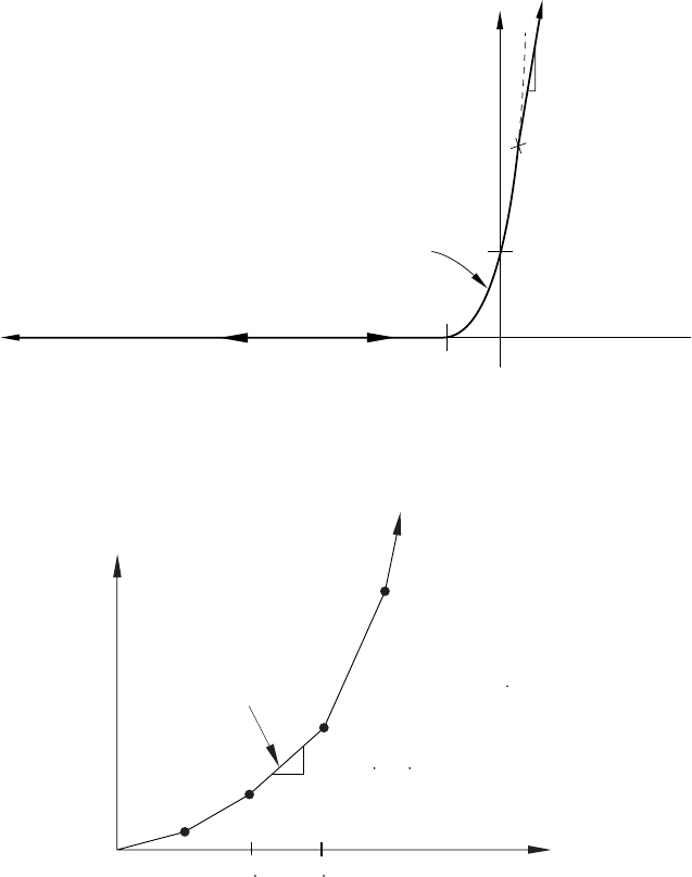
*SURFACE BEHAVIOR
Repeat this data line in ascending order of overclosure value as often as necessary to define
the overclosure as a function of pressure. A minimum of two data lines are required. The
pressure-overclosure relationship is extrapolated beyond the last overclosure point by continuing the
same slope (see Figure 18.47–3).
Clearance
Contact
pressure
Exponential pressure-overclosure relationship p0
c0
Kmax
Overclosure
Figure 18.47–1 Exponential pressure-overclosure relationship.
Overclosure
(i -1) d
i
d
K
i
= s
0
k
dflt
s
i-1
1
0
segment
i
P
ressure
i
k
L
s
s
r
d
= segment number
= default stiffness
= element length
= initial scale factor
= geometric scale factor
= overclosure factor
= r L = overclosure measur
e
dflt
elem
elem
0
Figure 18.47–2 Scale factor pressure-overclosure relationship.
18.47–4
ABAQUS Version 6.1 Module: ID:
Printed on:
*SURFACE BEHAVIOR
(pn,hn)
(p3,h3)
(p2,h2)
(0,h1)Overclosure
h
Pressure p
C
learance c
Figure 18.47–3 Pressure-overclosure relationship defined in tabular form.
18.47–5
ABAQUS Version 6.1 Module: ID:
Printed on:
*SURFACE FLAW
18.48 *SURFACE FLAW: Define geometry of surface flaws.
This option is used with line spring elements to define the geometry of the part-through crack of the shell.
Product: ABAQUS/Standard
Type: Model data
Level: Part, Part instance
Reference:
•“Line spring elements for modeling part-through cracks in shells,” Section 26.10.1 of the
ABAQUS Analysis User’s Manual
Required parameter:
SIDE
Set SIDE=POSITIVE or SIDE=NEGATIVE to indicate which surface is cracked.
Optional parameter:
INPUT
Set this parameter equal to the name of the alternate input file containing the data lines for this
option. See “Input syntax rules,” Section 1.2.1 of the ABAQUS Analysis User’s Manual, for the
syntax of such file names. If this parameter is omitted, it is assumed that the data follow the keyword
line.
Data lines to define the flaw:
First line:
1. Node number or node set label. This node or node set can be at either side of the crack for
element LS6.
2. Crack depth at this location.
Repeat this data line as often as necessary to define the crack depth at all nodal locations along the
crack.
18.48–1
ABAQUS Version 6.1 Module: ID:
Printed on:
*SURFACE INTERACTION
18.49 *SURFACE INTERACTION: Define surface interaction properties.
This option is used to create a surface interaction property definition. The surface interaction properties will
govern any contact interactions that reference this surface interaction.
Products: ABAQUS/Standard ABAQUS/Explicit
Type: Model data in ABAQUS/Standard; Model or history data in ABAQUS/Explicit
Level: Model in ABAQUS/Standard, Model or Step in ABAQUS/Explicit
References:
•“Surface properties for ABAQUS/Explicit contact pairs,” Section 29.4.2 of the ABAQUS Analysis
User’s Manual
•“Mechanical contact properties: overview,” Section 30.1.1 of the ABAQUS Analysis User’s Manual
•“Contact pressure-overclosure relationships,” Section 30.1.2 of the ABAQUS Analysis User’s Manual
•“Contact damping,” Section 30.1.3 of the ABAQUS Analysis User’s Manual
•“Frictional behavior,” Section 30.1.5 of the ABAQUS Analysis User’s Manual
•“User-defined interfacial constitutive behavior,” Section 30.1.6 of the ABAQUS Analysis User’s Manual
•“Breakable bonds,” Section 30.1.9 of the ABAQUS Analysis User’s Manual
•“Thermal contact properties,” Section 30.2.1 of the ABAQUS Analysis User’s Manual
•“Electrical contact properties,” Section 30.3.1 of the ABAQUS Analysis User’s Manual
•“Pore fluid contact properties,” Section 30.4.1 of the ABAQUS Analysis User’s Manual
Required parameter:
NAME
Set this parameter equal to a label that will be used to refer to this surface interaction property.
Use this label on the INTERACTION parameter of the *CONTACT PAIR option (for an
ABAQUS/Standard contact analysis or an ABAQUS/Explicit analysis using the contact pair
algorithm) or on the data line of the *CONTACT PROPERTY ASSIGNMENT option (for an
ABAQUS/Explicit analysis using the general contact algorithm) to assign this surface interaction
property to a contact interaction.
Optional parameters:
PAD THIC K N ESS
This parameter applies only to ABAQUS/Explicit analyses using the contact pair algorithm.
18.49–1
ABAQUS Version 6.1 Module: ID:
Printed on:
*SURFACE INTERACTION
Set this parameter equal to the thickness of an interfacial layer between the contacting surfaces.
The value can be positive or negative.
USER
Include this parameter if the surface interaction model is to be defined in user subroutine UINTER in
an ABAQUS/Standard analysis or in user subroutine VUINTER in an ABAQUS/Explicit analysis.
When this parameter is included, the *SURFACE BEHAVIOR option and its various suboptions
cannot be used under the same interaction definition.
Optional parameters if the USER parameter is used:
DEPVAR
Set DEPVAR equal to the number of state-dependent variables required for user subroutine UINTER
in an ABAQUS/Standard analysis or for user subroutine VUINTER in an ABAQUS/Explicit
analysis. The default is DEPVAR=0.
PROPERTIES
Set this parameter equal to the number of property values needed as data to define the surface
interaction model in user subroutine UINTER in an ABAQUS/Standard analysis or in user
subroutine VUINTER in an ABAQUS/Explicit analysis. The default is PROPERTIES=0. This
parameter is ignored when the option is used in association with a connector element.
UNSYMM
This parameter applies only to ABAQUS/Standard analyses.
Include this parameter when the interface stiffness matrix is not symmetric. This parameter
causes ABAQUS/Standard to use its unsymmetric equation solution procedures.
Optional data line for two-dimensional models in ABAQUS/Standard or for contact pairs
involving node-based surfaces in ABAQUS/Standard, if the USER parameter is omitted:
First (and only) line:
1. Out-of-plane thickness of the surface or cross-sectional area for every node in the node-based
surface. The default value is 1.0.
Data lines to define the surface interaction in an ABAQUS/Standard analysis if the USER
parameter is used:
First line:
1. Out-of-plane thickness of the surface for two-dimensional models or cross-sectional area for
every node in the node-based surface. The default value for both is 1.0. In other situations,
enter a blank line.
18.49–2
ABAQUS Version 6.1 Module: ID:
Printed on:
*SURFACE INTERACTION
Second line (needed only if the PROPERTIES parameter is used):
1. Enter the values of the surface interaction properties, eight per line.
Repeat this data line as often as necessary to define all material constants.
Data lines to define the surface interaction in an ABAQUS/Explicit analysis if the PROPERTIES
parameter is used:
First line:
1. Enter a blank line.
Second line:
1. Enter the values of the surface interaction properties, eight per line.
Repeat this data line as often as necessary to define all material constants.
18.49–3
ABAQUS Version 6.1 Module: ID:
Printed on:
*SURFACE PROPERTY
18.50 *SURFACE PROPERTY: Define surface properties for cavity radiation.
This option is used to define surface properties for cavity radiation analysis. It must immediately precede the
*EMISSIVITY option.
Product: ABAQUS/Standard
Type: Model data
Level: Model
References:
•“Cavity radiation,” Section 32.1.1 of the ABAQUS Analysis User’s Manual
•*EMISSIVITY
Required parameter:
NAME
Set this parameter equal to a label that will be used to refer to the property name for cross-referencing
to the surface definitions for which properties are being defined. Only element-based surfaces can
be used.
There are no data lines associated with this option.
18.50–1
ABAQUS Version 6.1 Module: ID:
Printed on:
*SURFACE PROPERTY ASSIGNMENT
18.51 *SURFACE PROPERTY ASSIGNMENT: Assign surface properties to a surface for the
general contact algorithm.
This option is used to modify surface properties for surfaces that are involved in general contact interactions
in ABAQUS/Explicit. It must be used in conjunction with the *CONTACT option.
Product: ABAQUS/Explicit
Type: Model or history data
Level: Model, Step
References:
•“Surface properties for general contact,” Section 29.3.2 of the ABAQUS Analysis User’s Manual
•*CONTACT
Required parameter:
PROPERTY
Use this parameter to specify the property type being assigned. To modify more than one type of
surface property, use this option more than once with different values for the PROPERTY parameter.
Set PROPERTY=FEATURE EDGE CRITERIA to control which feature edges should be
activated in the general contact domain.
Set PROPERTY=OFFSET FRACTION to assign the surface offset as a fraction of the surface
thickness.
Set PROPERTY=THICKNESS to assign the surface thickness.
Data lines for PROPERTY=FEATURE EDGE CRITERIA:
First line:
1. Surface name. A non-blank surface name is required if the ALL EDGES or PICKED EDGES
options are specified. If the surface name is omitted when using the PERIMETER EDGES,
NO FEATURE EDGES, or cutoff feature angle options, a default surface that encompasses the
entire general contact domain is assumed.
2. The “words” PERIMETER EDGES (default), the “words” ALL EDGES, the “words” PICKED
EDGES, the “words” NO FEATURE EDGES, or a scalar value representing the cutoff feature
angle (in degrees).
Repeat this data line as often as necessary. If the feature edge criteria assignments overlap, the last
assignment applies in the overlap region.
18.51–1
ABAQUS Version 6.1 Module: ID:
Printed on:
*SURFACE PROPERTY ASSIGNMENT
Data lines for PROPERTY=OFFSET FRACTION:
First line:
1. Surface name. If the surface name is omitted, a default surface that encompasses the entire
general contact domain is assumed. Faces specified on elements other than shell elements,
membrane elements, rigid elements, and surface elements will be ignored.
2. The “word” ORIGINAL (default), the “word” SPOS, the “word” SNEG, or a value between
–0.5 and 0.5. The offset defines the distance (as a fraction of the thickness) from the midsurface
to the reference surface (containing the nodes of the element). Positive values of the offset
are in the positive element normal direction. The default is ORIGINAL, which indicates that
the offset specified in element section definitions (via the OFFSET parameter on *SHELL
SECTION or *RIGID BODY) will be used.
Repeat this data line as often as necessary. If the offset fraction assignments overlap, the last assignment
applies in the overlap region.
Data lines for PROPERTY=THICKNESS:
First line:
1. Surface name. If the surface name is omitted, a default surface that encompasses the entire
general contact domain is assumed.
2. The “word” ORIGINAL (default), the “word” THINNING, or a scalar value representing a
nominal thickness.
3. A constant scaling factor (default is 1.0).
Repeat this data line as often as necessary. If the thickness assignments overlap, the last assignment
applies in the overlap region.
18.51–2
ABAQUS Version 6.1 Module: ID:
Printed on:
*SURFACE SECTION
18.52 *SURFACE SECTION: Specify section properties for surface elements.
This option is used to specify a surface element cross-section. It must be used in conjunction with the *REBAR
LAYER option.
Products: ABAQUS/Standard ABAQUS/Explicit
Type: Model data
Level: Part, Part instance
References:
•“Surface elements,” Section 26.7.1 of the ABAQUS Analysis User’s Manual
•“Defining reinforcement,” Section 2.2.3 of the ABAQUS Analysis User’s Manual
•*REBAR LAYER
Required parameter:
ELSET
Set this parameter equal to the name of the element set containing the surface elements for which
the section properties are being defined.
Optional parameter:
DENSITY
Set this parameter equal to the mass density per unit area of the surface element section.
There are no data lines associated with this option.
18.52–1
ABAQUS Version 6.1 Module: ID:
Printed on:
*SWELLING
18.53 *SWELLING: Specify time-dependent volumetric swelling.
This option is used to specify time-dependent metal swelling for a material. Swelling behavior defined
by this option is active only during *SOILS, CONSOLIDATION; *COUPLED TEMPERATURE-
DISPLACEMENT; and *VISCO procedures.
Product: ABAQUS/Standard
Type: Model data
Level: Model
References:
•“Rate-dependent plasticity: creep and swelling,” Section 18.2.4 of the ABAQUS Analysis User’s Manual
•“CREEP,” Section 1.1.1 of the ABAQUS User Subroutines Reference Manual
Optional parameters:
DEPENDENCIES
Set this parameter equal to the number of field variable dependencies included in the definition of the
volumetric swelling strain rate in addition to temperature. If this parameter is omitted, it is assumed
that the volumetric swelling strain rate is constant or depends only on temperature. See “Specifying
field variable dependence” in “Material data definition,” Section 16.1.2 of the ABAQUS Analysis
User’s Manual, for more information.
LAW
Set LAW=INPUT (default) to define the swelling behavior on the data lines.
Set LAW=USER to define the swelling behavior in user subroutine CREEP.
Data lines for LAW=INPUT:
First line:
1. Volumetric swelling strain rate.
2. Temperature.
3. First field variable.
4. Second field variable.
5. Etc., up to six field variables.
Subsequent lines (only needed if the DEPENDENCIES parameter has a value greater than six):
1. Seventh field variable.
18.53–1
ABAQUS Version 6.1 Module: ID:
Printed on:
*SWELLING
2. Etc., up to eight field variables per line.
Repeat this set of data lines as often as necessary to define the dependence of volumetric swelling strain
rate on temperature and other predefined field variables.
18.53–2
ABAQUS Version 6.1 Module: ID:
Printed on:
*SYMMETRIC MODEL GENERATION
18.54 *SYMMETRIC MODEL GENERATION: Create a three-dimensional model from an
axisymmetric or partial three-dimensional model.
This option is used to create a three-dimensional model by revolving the cross-section of an axisymmetric
model about a symmetry axis, by revolving a single three-dimensional sector about the symmetry axis, or by
combining two parts of a symmetric three-dimensional model where one part is the original model and the
other part is obtained by reflecting the original part through a line or a plane.
Product: ABAQUS/Standard
Type: Model data
Level: This option is not supported in a model defined in terms of an assembly of part instances.
Reference:
•“Symmetric model generation,” Section 10.3.1 of the ABAQUS Analysis User’s Manual
Required, mutually exclusive parameters:
PERIODIC
Use this parameter to indicate that a periodic three-dimensional model must be generated
by revolving a single three-dimensional sector of the model about the symmetry axis (see
Figure 18.54–1).
Set PERIODIC=CONSTANT (default) to indicate that each generated sector in the periodic
model has a constant angle.
Set PERIODIC=VARIABLE to indicate that each generated sector in the periodic model can
have a variable angle in the circumferential direction.
In both cases each sector always has the same geometry and mesh. The surfaces on both sides
of the original sector must be planar when PERIODIC=VARIABLE. If the surface meshes on either
side of the original sector are not matched completely, constraints between the neighboring pairs of
corresponding surfaces specified on the data lines will be applied with an automatically generated
*TIE option when the periodic three-dimensional model is generated.
REFLECT
Set REFLECT=LINE to indicate that a three-dimensional model must be generated by reflecting a
partial three-dimensional model through a symmetry line (Figure 18.54–3).
Set REFLECT=PLANE to indicate that a three-dimensional model must be generated by
reflecting a partial three-dimensional model through a symmetry plane (Figure 18.54–4).
REVOLVE
Include this parameter to indicate that a three-dimensional model must be generated by revolving
the cross-section of an axisymmetric mesh about the symmetry axis. See Figure 18.54–2.
18.54–1
ABAQUS Version 6.1 Module: ID:
Printed on:
*SYMMETRIC MODEL GENERATION
Optional parameters:
ELEMENT OFFSET
Set this parameter equal to an integer to define the offset for element numbering. When the
REVOLVE parameter is used, the offset is added to each element number on the previous
cross-section to obtain the numbering of the elements on the next cross-section, starting at the
reference cross-section, . The reference cross-section uses the same numbering as the
original axisymmetric model. When the REFLECT parameter is used, the offset is added to the
original element numbers to define the numbering on the reflected part. The default and minimum
value is the largest element number used in the original model.
FILE NAME
Set this parameter equal to the name of an external file (without an extension) to which keyword
and data lines for the model definition will be written. The extension .axi will be added to the
file name provided by the user. See “Input syntax rules,” Section 1.2.1 of the ABAQUS Analysis
User’s Manual, for the syntax of such file names.
NODE OFFSET
Set this parameter equal to an integer to define the offset used for node numbering. When the
REVOLVE parameter is used, the offset is added to each node number on the previous cross-section
to obtain the numbering of the nodes on the next cross-section, starting at the reference cross-section,
. The reference cross-section uses the same numbering as the original axisymmetric model.
When the REFLECT parameter is used, the offset is added to the original node numbers to define
the numbering on the reflected part. The default and minimum value is the largest node number
used in the original model.
TOLERANCE
Set this parameter equal to the distance to be used in the search for duplicate nodes. Duplicate nodes
on the axis of revolution of a revolved model and on the connection plane between the two parts of
a reflected model will be eliminated. The default is 1.0% of the average element dimension.
Data lines if each generated sector in the periodic model has a constant angle
(PERIODIC=CONSTANT):
First line:
1. X-coordinate of point a.
2. Y-coordinate of point a.
3. Z-coordinate of point a.
4. X-coordinate of point b.
5. Y-coordinate of point b.
6. Z-coordinate of point b.
18.54–2
ABAQUS Version 6.1 Module: ID:
Printed on:
*SYMMETRIC MODEL GENERATION
Second line:
1. Segment angle, (in degrees), of the original three-dimensional sector. .
2. Number of three-dimensional repetitive sectors, including the original sector in the generated
periodic model. The default is 1.
Third line (needed if the surface meshes on either side of the original sector are not matched
completely):
1. The surface name on one side of the original sector.
2. The corresponding surface name on the other side of the original sector, measured at a positive
angle, , around the revolving axis.
3. Tolerance distance within which nodes on one surface of a sector must lie from the
corresponding surface of the neighboring sector to be constrained. Nodes on the surface of
the sector that are further away from the corresponding surface of the neighboring sector than
this distance are not constrained. The default value for this tolerance distance is 5% of the
typical element size in the surfaces of the original sector.
4. Include the “word” SURFACE (default) to generate a surface-to-surface type of constraint or
the “word” NODE to generate a node-to-surface type of constraint.
Repeat the third data line as often as necessary to define pairs of corresponding surfaces on each side
of the original repetitive sector. Constraints between the neighboring pairs of corresponding surfaces
will be applied with an automatically generated *TIE option when the periodic three-dimensional model
is generated.
Data lines if each generated sector in the periodic model has a variable angle
(PERIODIC=VARIABLE):
First line:
1. X-coordinate of point a.
2. Y-coordinate of point a.
3. Z-coordinate of point a.
4. X-coordinate of point b.
5. Y-coordinate of point b.
6. Z-coordinate of point b.
Second line:
1. Segment angle, (in degrees), of the original three-dimensional sector. .
2. Number of three-dimensional sectors that have the same angle as the original sector to be
generated, including the original sector. The default is 1.
Third line:
1. Number of additional three-dimensional sectors to be generated.
18.54–3
ABAQUS Version 6.1 Module: ID:
Printed on:

*SYMMETRIC MODEL GENERATION
2. Angular scaling factor in the circumferential direction with respect to the original sector. The
default is 1.0.
Repeat the third data line as often as necessary to define all the sectors of the model in the circumferential
direction.
Subsequent lines (needed if the surface meshes on either side of the original sector are not matched
completely):
1. The surface name on one side of the original sector.
2. The corresponding surface name on the other side of the original sector, measured at a positive
angle, , around the revolving axis.
3. Tolerance distance within which nodes on one surface of a sector must lie from the
corresponding surface of the neighboring sector to be constrained. Nodes on the surface of
the sector that are further away from the corresponding surface of the neighboring sector than
this distance are not constrained. The default value for this tolerance distance is 5% of the
typical element size in the surfaces of the original sector.
4. Include the “word” SURFACE (default) to generate a surface-to-surface type of constraint or
the “word” NODE to generate a node-to-surface type of constraint.
Repeat the subsequent data line as often as necessary to define more pairs of corresponding surfaces
on each side of the original sector. Constraints between the neighboring pairs of corresponding surfaces
will be applied with the automatically generated *TIE option when the periodic three-dimensional model
is generated.
Data line if REFLECT=LINE:
First (and only) line:
1. X-coordinate of point a.
2. Y-coordinate of point a.
3. Z-coordinate of point a.
4. X-coordinate of point b.
5. Y-coordinate of point b.
6. Z-coordinate of point b.
Data lines if REFLECT=PLANE:
First line:
1. X-coordinate of point a.
2. Y-coordinate of point a.
3. Z-coordinate of point a.
4. X-coordinate of point b.
5. Y-coordinate of point b.
6. Z-coordinate of point b.
18.54–4
ABAQUS Version 6.1 Module: ID:
Printed on:

*SYMMETRIC MODEL GENERATION
Second line:
1. X-coordinate of point c.
2. Y-coordinate of point c.
3. Z-coordinate of point c.
Data lines if the REVOLVE parameter is included:
First line:
1. X-coordinate of point a.
2. Y-coordinate of point a.
3. Z-coordinate of point a.
4. X-coordinate of point b.
5. Y-coordinate of point b.
6. Z-coordinate of point b.
Second line:
1. X-coordinate of point c.
2. Y-coordinate of point c.
3. Z-coordinate of point c.
Third line:
1. Segment angle, , through which the cross-section must be revolved. .The
segments are connected, so, except for the first segment, each segment starts at the end point
of the segment given on the previous data line.
2. Number of subdivisions or elements to be used in the segment. The default is 1. A single
element subdivision must not exceed 45° when general elements are used or 180° when
cylindrical elements are used.
3. Bias ratio to be used in the spacing of nodes generated over the segment. The value is set to the
ratio of adjacent angles between nodes along each arc of nodes generated. Thus, if the value is
less than one, the nodes are concentrated toward the beginning of the segment; and if the value
is greater than one, the nodes are concentrated toward the end of the segment. The default is
1.0.
4. Include the “word” GENERAL (default) to generate general three-dimensional elements or the
“word” CYLINDRICAL to generate cylindrical elements.
Repeat the third data line as often as necessary to define the discretization of the model in the
circumferential direction.
18.54–5
ABAQUS Version 6.1 Module: ID:
Printed on:
*SYMMETRIC MODEL GENERATION
b
a
θ
y
x
z
Figure 18.54–1 Revolving a single three-dimensional repetitive
sector to create a periodic structure.
b
z
c
r
a
z
Z
Y
X
θ
reference
cross-section
at θ = 0
Figure 18.54–2 Revolving an axisymmetric cross-section.
18.54–6
ABAQUS Version 6.1 Module: ID:
Printed on:
*SYMMETRIC MODEL GENERATION
87
5
4
6
3
1
23 + n
7 + n
6 + n 5 + n
4 + n
1 +
n
2 + n
8 + n
a
b
reflection line
Figure 18.54–3 Reflecting a three-dimensional model through line ab with node offset n.
18.54–7
ABAQUS Version 6.1 Module: ID:
Printed on:
*SYMMETRIC MODEL GENERATION
5
87
4
6
3
1
22 + n
6 + n
7 + n 8 + n
1 + n
4 +
n
5 + n
a
b
c
reflection plane
3 + n
Figure 18.54–4 Reflecting a three-dimensional model through a plane abc with node offset n.
18.54–8
ABAQUS Version 6.1 Module: ID:
Printed on:
*SYMMETRIC RESULTS TRANSFER
18.55 *SYMMETRIC RESULTS TRANSFER: Import results from an axisymmetric or partial
three-dimensional analysis.
This option is used to transfer a solution from an axisymmetric analysis to a three-dimensional model or to
transfer the solution of a partial three-dimensional model to a full three-dimensional model. It can be used
only in conjunction with the *SYMMETRIC MODEL GENERATION option.
Product: ABAQUS/Standard
Type: Model data
Level: This option is not supported in a model defined in terms of an assembly of part instances.
References:
•“Transferring results from a symmetric mesh or a partial three-dimensional mesh to a full
three-dimensional mesh,” Section 10.3.2 of the ABAQUS Analysis User’s Manual
•“Symmetric model generation,” Section 10.3.1 of the ABAQUS Analysis User’s Manual
•*SYMMETRIC MODEL GENERATION
Optional parameters:
STEP
Set this parameter equal to the step number on the restart file at which the results must be obtained.
If this parameter is omitted, the results will be obtained at the last available step found on the restart
file.
INC
Set this parameter equal to the increment number on the restart file at which the results must be
obtained. If this parameter is omitted, the results will be obtained at the end of the step specified by
the STEP parameter.
ITERATION
This parameter is relevant only if the solution is transferred from a previous direct cyclic analysis.
Set this parameter equal to the iteration number on the restart file at which the results must be
obtained. Since restart information can be written only at the end of an iteration in a direct cyclic
analysis, the INC parameter is irrelevant and is ignored if the ITERATION parameter is specified.
If this parameter is omitted, the results will be obtained at the end of the step specified by the
STEP parameter.
UNBALANCED STRESS
Set UNBALANCED STRESS=STEP (default) if the stress unbalance is to be resolved in the first
increment.
18.55–1
ABAQUS Version 6.1 Module: ID:
Printed on:
*SYMMETRIC RESULTS TRANSFER
Set UNBALANCED STRESS=RAMP if the stress unbalance is to be resolved linearly over
the step.
There are no data lines associated with this option.
18.55–2
ABAQUS Version 6.1 Module: ID:
Printed on:
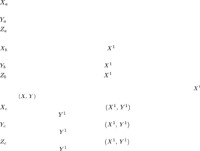
*SYSTEM
18.56 *SYSTEM: Specify a local coordinate system in which to define nodes.
This option is used to define nodes by accepting coordinates relative to a specified local rectangular coordinate
system and generating the nodal coordinates in the global coordinate system.
Products: ABAQUS/Standard ABAQUS/Explicit
Type: Model data
Level: Part, Part instance
Reference:
•“Node definition,” Section 2.1.1 of the ABAQUS Analysis User’s Manual
There are no parameters associated with this option.
Data lines to define a local coordinate system:
First line:
1. , global X-coordinate of the origin of the local coordinate system (point ain
Figure 18.56–1).
2. , global Y-coordinate of the origin of the local coordinate system.
3. , global Z-coordinate of the origin of the local coordinate system.
The following entries are not needed for a pure translation:
4. , global X-coordinate of a point on the -axis of the local coordinate system (point bin
Figure 18.56–1).
5. , global Y-coordinate of a point on the -axis of the local coordinate system.
6. , global Z-coordinate of a point on the -axis of the local coordinate system.
Second line (optional; if not provided, the Z-axis direction remains unchanged, and the -axis
is projected onto the plane):
1. , global X-coordinate of a point in the plane of the local coordinate system, on
the side of the positive -axis (for example, point cin Figure 18.56–1).
2. , global Y-coordinate of a point in the plane of the local coordinate system, on
the side of the positive -axis.
3. , global Z-coordinate of a point in the plane of the local coordinate system, on
the side of the positive -axis.
18.56–1
ABAQUS Version 6.1 Module: ID:
Printed on:
*SYSTEM
Z
Y
X
X
Y
Z1
1
1(loca
l)
(global)
ab
c
Figure 18.56–1 Local coordinate system.
18.56–2
ABAQUS Version 6.1 Module: ID:
Printed on:
T
19. T
ABAQUS Version 6.1 Module: ID:
Printed on:
*TEMPERATURE
19.1 *TEMPERATURE: Specify temperature as a predefined field.
This option is used to specify temperature as a predefined field during an analysis.
To use this option in a restart analysis of ABAQUS/Standard, either *TEMPERATURE or *INITIAL
CONDITIONS, TYPE=TEMPERATURE must have been specified in the original analysis.
Products: ABAQUS/Standard ABAQUS/Explicit
Type: History data
Level: Step
References:
•“Predefined fields,” Section 27.6.1 of the ABAQUS Analysis User’s Manual
•“UTEMP,” Section 1.1.41 of the ABAQUS User Subroutines Reference Manual
Optional parameters for using the data line format:
AMPLITUDE
Set this parameter equal to the name of the amplitude curve that gives the time variation of the
temperature throughout the step (see “Amplitude curves,” Section 27.1.2 of the ABAQUS Analysis
User’s Manual).
If this parameter is omitted in an ABAQUS/Standard analysis, the reference magnitude is
applied immediately at the beginning of the step or linearly over the step, depending on the value
assigned to the AMPLITUDE parameter on the *STEP option (see “Procedures: overview,”
Section 6.1.1 of the ABAQUS Analysis User’s Manual). If this parameter is omitted in an
ABAQUS/Explicit analysis, a linear interpolation is done over the step.
INPUT
Set this parameter equal to the name of the alternate input file containing the data lines for this
option. See “Input syntax rules,” Section 1.2.1 of the ABAQUS Analysis User’s Manual, for the
syntax of such file names. If this parameter is omitted, it is assumed that the data follow the keyword
line.
OP
Set OP=MOD (default) for existing *TEMPERATURE values to remain, with this option modifying
existing temperatures or defining additional temperatures.
Set OP=NEW if all existing *TEMPERATURE values should be removed. New temperatures
can be defined.
A temperature that is removed via OP=NEW is reset to the value given on the *INITIAL
CONDITIONS option or to zero if no initial temperature was defined. If temperatures are being
returned to their initial condition values, the AMPLITUDE parameter described above does not
19.1–1
ABAQUS Version 6.1 Module: ID:
Printed on:
*TEMPERATURE
apply. Rather, the AMPLITUDE parameter given on the *STEP option governs the behavior
in an ABAQUS/Standard analysis, and the temperatures are always ramped back to their initial
conditions in ABAQUS/Explicit analyses. If temperatures are being reset to new values (not to
initial conditions) via OP=NEW, the AMPLITUDE parameter described above applies.
Required parameter for reading temperatures from the results or output database file:
FILE
Set this parameter equal to the name of the results or output database file from which the data are
read. The file extension is optional; however, if both .fil and .odb files exist, the results file will
be used if the INTERPOLATE parameter is omitted. If the INTERPOLATE parameter is used, an
output database file must exist. See “Input syntax rules,” Section 1.2.1 of the ABAQUS Analysis
User’s Manual, for the syntax of such file names. This parameter cannot be used in a *STATIC,
RIKS analysis step.
Optional parameters for reading temperatures from the results or output database file:
ABSOLUTE EXTERIOR TOLERANCE
This parameter is relevant only for use with the INTERPOLATE parameter. Set this parameter equal
to the absolute value (given in the units used in the model) by which nodes of the current model may
lie outside the region of the model in the output database specified by the FILE parameter. If this
parameter is not used or has a value of 0.0, the EXTERIOR TOLERANCE parameter will apply.
EXTERIOR TOLERANCE
This parameter is relevant only for use with the INTERPOLATE parameter. Set this parameter equal
to the fraction of the average element size by which nodes of the current model may lie outside the
region of the elements of the model in the output database specified by the FILE parameter. The
default value is 0.05.
If both tolerance parameters are specified, ABAQUS uses the tighter tolerance.
BSTEP
Set this parameter equal to the step number (of the analysis whose results or output database file is
being used as input to this option) that begins the history data to be read. If no value is supplied,
ABAQUS will begin reading temperature data from the first step available on the file read.
BINC
Set this parameter equal to the increment number (of the analysis whose results or output database
file is being used as input to this option) that begins the history data to be read. If no value is supplied,
ABAQUS will begin reading temperature data from the first increment available (excluding any
zero increments if the results file was written in ABAQUS/Standard using *FILE FORMAT, ZERO
INCREMENT) for step BSTEP on the results or output database file.
19.1–2
ABAQUS Version 6.1 Module: ID:
Printed on:

*TEMPERATURE
ESTEP
Set this parameter equal to the step number (of the analysis whose results or output database file
is being used as input to this option) that ends the history data to be read. If no value is supplied,
ESTEP is taken as equal to BSTEP.
EINC
Set this parameter equal to the increment number (of the analysis whose results or output database
file is being used as input to this option) that ends the history data to be read. If no value is supplied,
EINC is taken as the last available increment of step ESTEP on the file read.
BTRAMP
Set this parameter equal to the starting time (measured relative to the total step time period) after
which the temperatures read from the results file will be ramped to their initial condition values.
The default value is , in which case no temperature ramping takes place. This feature is used to
create a cyclic temperature history from a prior heat transfer analysis that is not cyclic.
INTERPOLATE
Include this parameter to indicate that the temperature field needs to be interpolated between
dissimilar meshes. This feature is used to read temperatures from an output database file
generated during a heat transfer analysis or generated during a global model analysis used with
the submodeling capability. This parameter and the MIDSIDE parameter are mutually exclusive.
If the heat transfer analysis uses first-order elements and the current mesh is the same but uses
second-order elements, use the MIDSIDE parameter instead.
MIDSIDE
Include this parameter to indicate that midside node temperatures in second-order elements are to be
interpolated from corner node temperatures. This feature is used to read temperatures from a results
or an output database file generated during a heat transfer analysis using first-order elements. This
parameter and the INTERPOLATE parameter are mutually exclusive.
Required parameter for defining data in user subroutine UTEMP:
USER
This parameter applies only to ABAQUS/Standard analyses.
Include this parameter to indicate that user subroutine UTEMP will be used to define
temperature values. UTEMP will be called for each node given on the data lines.
If values are also given on the data lines, these values will be ignored. If a results or an output
database file has been specified in addition to user subroutine UTEMP, values read from this file will
be passed into UTEMP for possible modification.
Data lines to define gradients of temperature in beams and shells:
First line:
1. Node set or node number.
19.1–3
ABAQUS Version 6.1 Module: ID:
Printed on:

*TEMPERATURE
2. Reference temperature value. If the AMPLITUDE parameter is present, this value and
subsequent temperature values will be modified by the AMPLITUDE specification.
3. Temperature gradient in the -direction for beams or temperature gradient through the
thickness for shells.
4. Temperature gradient in the -direction for beams.
Repeat this data line as often as necessary to define temperatures at different nodes or node sets.
Data lines to define temperatures at temperature points in beams and shells:
First line:
1. Node set or node number.
2. Temperature at the first temperature point. If the AMPLITUDE parameter is present, this value
and subsequent temperature values will be modified by the AMPLITUDE specification.
3. Temperature of the second temperature point.
4. Temperature of the third temperature point.
5. Etc., up to seven temperatures.
Subsequent lines (only needed if there are more than seven temperature points in the element):
1. Temperature of the eighth temperature point.
2. Etc., up to eight temperatures per line.
If more than seven temperature values are needed at any node, continue on the next line. It may
be necessary to leave blank data lines for some nodes if any other node in the model has more than
seven temperature points because the total number of temperatures that ABAQUS expects to read
for any node is based on the maximum number of temperature values of all the nodes in the model.
These trailing initial values will be zero and will not be used in the analysis.
Repeat this set of data lines as often as necessary to define temperatures at different nodes or node sets.
Data lines to define temperatures for solid or frame elements using the data line format:
First line:
1. Node set or node number.
2. Temperature. If the AMPLITUDE parameter is present, this value will be modified by the
AMPLITUDE specification.
Repeat this data line as often as necessary to prescribe temperature at different nodes or node sets.
To read temperatures from an ABAQUS results or output database file:
No data lines are used when temperature data are read from a results or an output database file.
19.1–4
ABAQUS Version 6.1 Module: ID:
Printed on:
*TEMPERATURE
Data lines to define temperatures using user subroutine UTEMP:
First line:
1. Node set or node number.
Repeat this data line as often as necessary. UTEMP will be called for each node listed.
19.1–5
ABAQUS Version 6.1 Module: ID:
Printed on:
*TENSILE FAILURE
19.2 *TENSILE FAILURE: Specify a tensile failure model and criterion.
This option is used with the Mises or the Johnson-Cook plasticity models or the equation of state model
to specify a tensile failure model and criterion. It must be used in conjunction with the *PLASTIC,
HARDENING=ISOTROPIC option; the *PLASTIC, HARDENING=JOHNSON COOK option; or the
*EOS option.
Product: ABAQUS/Explicit
Type: Model data
Level: Model
References:
•“Equation of state,” Section 17.9.1 of the ABAQUS Analysis User’s Manual
•“Classical metal plasticity,” Section 18.2.1 of the ABAQUS Analysis User’s Manual
•“Johnson-Cook plasticity,” Section 18.2.7 of the ABAQUS Analysis User’s Manual
•“Dynamic failure models,” Section 18.2.8 of the ABAQUS Analysis User’s Manual
•*EOS
•*PLASTIC
Optional parameters:
DEPENDENCIES
Set this parameter equal to the number of field variable dependencies included in the definition of
the hydrostatic cutoff stress, in addition to temperature. If this parameter is omitted, it is assumed
that the hydrostatic cutoff stress is constant or depends only on temperature. See “Using the
DEPENDENCIES parameter to define field variable dependence” in “Material data definition,”
Section 16.1.2 of the ABAQUS Analysis User’s Manual, for more information.
ELEMENT DELETION
Set ELEMENT DELETION=YES (default) to allow element deletion when the failure criterion is
met.
Set ELEMENT DELETION=NO to allow BRITTLE/DUCTILE-type failure for the deviatoric
and hydrostatic parts of stresses.
Required parameters for use with ELEMENT DELETION=NO:
PRESSURE
Set PRESSURE=BRITTLE to model the case where the pressure stress is required to be
compressive when the failure criterion is met.
19.2–1
ABAQUS Version 6.1 Module: ID:
Printed on:
*TENSILE FAILURE
Set PRESSURE=DUCTILE to model the case where the pressure stress will be limited by the
hydrostatic cutoff stress when the failure criterion is met.
SHEAR
Set SHEAR=BRITTLE to model the case where the deviatoric stresses will be set to zero when the
failure criterion is met.
Set SHEAR=DUCTILE to model the case where the deviatoric stresses will be unaffected
when the failure criterion is met.
Data lines to specify a tensile failure model:
First line:
1. Hydrostatic cutoff stress (positive in tension). (Units of FL−2 .)
2. Temperature.
3. First field variable.
4. Second field variable.
5. Etc., up to six field variables.
Subsequent lines (only needed if the DEPENDENCIES parameter has a value greater than six):
1. Seventh field variable.
2. Etc., up to eight field variables per line.
Repeat this set of data lines as often as necessary to define the dependence of hydrostatic cutoff stress
as a function of temperature and other predefined field variables.
19.2–2
ABAQUS Version 6.1 Module: ID:
Printed on:

*TENSION STIFFENING
19.3 *TENSION STIFFENING: Define the retained tensile stress normal to a crack in a
*CONCRETE model.
This option is used to define the retained tensile stress normal to a crack as a function of the deformation
in the direction of the normal to the crack. It must be used with and appear after the *CONCRETE option.
The *TENSION STIFFENING option can also be used in conjunction with the *SHEAR RETENTION and
*FAILURE RATIOS options.
Product: ABAQUS/Standard
Type: Model data
Level: Model
References:
•“Concrete smeared cracking,” Section 18.5.1 of the ABAQUS Analysis User’s Manual
•*CONCRETE
•*FAILURE RATIOS
•*SHEAR RETENTION
Optional parameters:
DEPENDENCIES
Set this parameter equal to the number of field variable dependencies included in the definition of the
postcracking behavior, in addition to temperature. If this parameter is omitted, it is assumed that the
postcracking behavior depends only on temperature. See “Specifying field variable dependence”
in “Material data definition,” Section 16.1.2 of the ABAQUS Analysis User’s Manual, for more
information.
TYPE
Set TYPE=DISPLACEMENT to define the postcracking behavior by entering the displacement,
, at which a linear loss of strength after cracking gives zero stress.
Set TYPE=STRAIN (default) to specify the postcracking behavior by entering the postfailure
stress-strain relationship directly.
Data lines if the parameter TYPE=STRAIN is included (default):
First line:
1. Fraction of remaining stress to stress at cracking.
2. Absolute value of the direct strain minus the direct strain at cracking.
3. Temperature.
19.3–1
ABAQUS Version 6.1 Module: ID:
Printed on:

*TENSION STIFFENING
4. First field variable.
5. Second field variable.
6. Etc.,uptofivefieldvariables.
The first point at each value of temperature must be a stress fraction of 1.0 at a strain of 0.0.
Subsequent lines (only needed if the DEPENDENCIES parameter has a value greater than five):
1. Sixth field variable.
2. Etc., up to eight field variables per line.
Repeat this set of data lines as often as necessary to define the dependence of the postcracking behavior
on temperature and other predefined field variables.
Data lines if the parameter TYPE=DISPLACEMENT is included:
First line:
1. Displacement, , at which a linear loss of strength after cracking gives zero stress. (Units of
L.)
2. Temperature.
3. First field variable.
4. Second field variable.
5. Etc., up to six field variables.
Subsequent lines (only needed if the DEPENDENCIES parameter has a value greater than six):
1. Seventh field variable.
2. Etc., up to eight field variables per line.
Repeat this set of data lines as often as necessary to define the dependence of the postcracking behavior
on temperature and other predefined field variables.
19.3–2
ABAQUS Version 6.1 Module: ID:
Printed on:
*THERMAL EXPANSION
19.4 *THERMAL EXPANSION: Define the thermal expansion behavior of beams.
This option can be used only in conjunction with the *BEAM GENERAL SECTION,
SECTION=NONLINEAR GENERAL option.
Products: ABAQUS/Standard ABAQUS/Explicit
Type: Model data
Level: Part, Part instance
References:
•“Using a general beam section to define the section behavior,” Section 23.3.7 of the ABAQUS Analysis
User’s Manual
•*BEAM GENERAL SECTION
Optional parameter:
DEPENDENCIES
Set this parameter equal to the number of field variable dependencies for the thermal-expansion
coefficient, in addition to temperature. If this parameter is omitted, it is assumed that the thermal-
expansion coefficient is constant or depends only on temperature. See “Specifying field variable
dependence” in “Material data definition,” Section 16.1.2 of the ABAQUS Analysis User’s Manual,
for more information.
Data lines to define the thermal expansion behavior:
First line:
1. Coefficient of thermal expansion.
2. Temperature.
3. First field variable.
4. Second field variable.
5. Etc., up to six field variables.
Subsequent lines (only needed if the DEPENDENCIES parameter has a value greater than six):
1. Seventh field variable.
2. Etc., up to eight field variables per line.
Repeat this set of data lines as often as necessary to define the thermal expansion coefficient as a
function of temperature and other predefined field variables.
19.4–1
ABAQUS Version 6.1 Module: ID:
Printed on:
*TIE
19.5 *TIE: Define surface-based tie and cyclic symmetry constraints or coupled acoustic-
structural interactions.
This option is used to impose tie constraints, cyclic symmetry constraints, or coupled acoustic-structural
interactions between pairs of surfaces.
Products: ABAQUS/Standard ABAQUS/Explicit
Type: Model data
Level: Part, Part instance, Assembly
References:
•“Mesh tie constraints,” Section 28.3.1 of the ABAQUS Analysis User’s Manual
•“Defining element-based surfaces,” Section 2.3.2 of the ABAQUS Analysis User’s Manual
•“Defining node-based surfaces,” Section 2.3.3 of the ABAQUS Analysis User’s Manual
•“Analysis of models that exhibit cyclic symmetry,” Section 10.3.3 of the ABAQUS Analysis User’s
Manual
•“Acoustic, shock, and coupled acoustic-structural analysis,” Section 6.9.1 of the ABAQUS Analysis
User’s Manual
Required parameter:
NAME
Set this parameter equal to a label that will be used to refer to the constraint.
Optional, mutually exclusive parameters:
POSITION TOLERANCE
Set this parameter equal to a cutoff distance that is used to determine which nodes on the slave
surface are tied to the master surface. The calculation of the distance between the slave and master
surface for a particular slave node depends on factors such as shell element thickness, the setting of
the TYPE parameter, and the types of surfaces involved. Slave nodes that do not satisfy the position
tolerance are not tied to the master surface. The default value for this tolerance distance is 5% of
the typical element size in the master surface. If a node-based master surface is used, the default
tolerance distance is based on the average distance between nodes in the master surface.
TIED NSET
Set this parameter equal to the node set label of the node set that includes the nodes on the slave
surface that will be tied to the master surface. Nodes not included in this node set will not be tied.
19.5–1
ABAQUS Version 6.1 Module: ID:
Printed on:
*TIE
Optional parameters:
ADJUST
Set ADJUST=YES (default) to move all tied nodes on the slave surface onto the master surface in
the initial configuration, without any strain.
Set ADJUST=NO if the slave nodes will not be moved. This is the default if the slave surface
belongs to a substructure or if one or more of the surfaces is beam element-based.
CONSTRAINT RATIO
This parameter applies only when two surfaces with rotational degrees of freedom are tied with an
offset but the NO ROTATION parameter is used.
Set this parameter equal to the fractional distance between the master reference surface and
the slave node at which the translational constraint should act. By default, ABAQUS will attempt
to choose this distance such that the translational constraint acts precisely at the interface.
CYCLIC SYMMETRY
This parameter applies only to ABAQUS/Standard analyses.
Include this parameter to invoke a constraint between the faces bounding a repetitive sector of
a cyclic symmetric structure. This parameter can be used only in conjunction with the *CYCLIC
SYMMETRY MODEL option.
NO ROTATION
Include this parameter if rotation degrees of freedom should not be tied. If this parameter is omitted,
any existing rotation degrees of freedom will be tied if applicable, in addition to the translation
degrees of freedom.
NO THICKNESS
Include this parameter to ignore shell thickness effects in calculations involving position tolerances
and adjustments for initial gaps.
TYPE
Set TYPE=SURFACE TO SURFACE (default for most cases in ABAQUS/Standard) to have the tie
coefficients generated such that stress accuracy is optimized for the specified surface type pairings.
Set TYPE=NODE TO SURFACE (default for all cases in ABAQUS/Explicit) to have the tie
coefficients generated according to the interpolation functions at the point where the slave node
projects onto the master surface.
Data lines to define the surfaces forming the constraint pairs:
First line:
1. The slave surface name.
2. The master surface name.
Repeat this data line as often as necessary to define all the surfaces forming the constraint pairs. Each
data line defines a pair of surfaces that will be tied together.
19.5–2
ABAQUS Version 6.1 Module: ID:
Printed on:

*TIME POINTS
19.6 *TIME POINTS: Specify time points at which data are written to the output database
or restart files, or specify time points in the loading history at which the response of
a structure will be evaluated in a direct cyclic analysis.
This option is used to specify time points at which data are written to the output database or restart files or, if
it is used in conjunction with the *DIRECT CYCLIC option, to specify time points in the loading history at
which the response of a structure will be evaluated.
Products: ABAQUS/Standard ABAQUS/Explicit
Type: Model data
Level: Model
References:
•*DIRECT CYCLIC
•*OUTPUT
Required parameter:
NAME
Set this parameter equal to a label that will be used to refer to the time points.
Optional parameters:
GENERATE
If this parameter is included, each data line should give a starting time point, ; an ending time
point, ; and the time increment between these two specified time points, .
INPUT
Set this parameter equal to the name of the alternate input file containing the data lines for this
option. See “Input syntax rules,” Section 1.2.1 of the ABAQUS Analysis User’s Manual, for the
syntax of such file names. If this parameter is omitted, it is assumed that the data follow the keyword
line.
19.6–1
ABAQUS Version 6.1 Module: ID:
Printed on:
*TIME POINTS
Data lines if the GENERATE parameter is omitted:
First line:
1. List of time points; the points must be arranged in ascending order.
Repeat this data line as often as necessary. Up to eight entries are allowed per line. If you use the *TIME
POINTS option in conjunction with the *DIRECT CYCLIC option, the listed time points must include the
starting time and ending time in a single loading cycle. The time points must be specified in the step time.
Data lines if the GENERATE parameter is included:
First line:
1. Starting time point.
2. Ending time point, which must be later than the starting time point.
3. Increment in time between the two specified time points.
Repeat this data line as often as necessary. If you use the *TIME POINTS option in conjunction with the
*DIRECT CYCLIC option, the listed time points must include the starting time and ending time in a single
loading cycle. The time points must be specified in the step time.
19.6–2
ABAQUS Version 6.1 Module: ID:
Printed on:
*TORQUE
19.7 *TORQUE: Define the torsional behavior of beams.
This option can be used only in conjunction with the *BEAM GENERAL SECTION,
SECTION=NONLINEAR GENERAL option.
Products: ABAQUS/Standard ABAQUS/Explicit
Type: Model data
Level: Part, Part instance
References:
•“Using a general beam section to define the section behavior,” Section 23.3.7 of the ABAQUS Analysis
User’s Manual
•*BEAM GENERAL SECTION
Optional parameters (if neither ELASTIC nor LINEAR is included, elastic-plastic response is
assumed):
DEPENDENCIES
Set this parameter equal to the number of field variable dependencies included in the torque–twist
relationship, in addition to temperature. If this parameter is omitted, it is assumed that the
torque–twist relationship is constant or depends only on temperature. See “Specifying field
variable dependence” in “Material data definition,” Section 16.1.2 of the ABAQUS Analysis
User’s Manual, for more information.
ELASTIC
Include this parameter if the torque–twist relationship is nonlinear but elastic.
LINEAR
Include this parameter if the torque varies linearly with twist.
Data lines if the LINEAR parameter is included:
First line:
1. Torsional stiffness of the section.
2. Temperature.
3. First field variable.
4. Second field variable.
5. Etc., up to six field variables.
19.7–1
ABAQUS Version 6.1 Module: ID:
Printed on:
*TORQUE
Subsequent lines (only needed if the DEPENDENCIES parameter has a value greater than six):
1. Seventh field variable.
2. Etc., up to eight field variables per line.
Repeat this set of data lines as often as necessary to define the torsional stiffness as a function of
temperature and other predefined field variables.
Data lines if the LINEAR parameter is omitted:
First line:
1. Torque.
2. Twist.
3. Temperature.
4. First field variable.
5. Second field variable.
6. Etc.,uptofivefieldvariables.
Subsequent lines (only needed if the DEPENDENCIES parameter has a value greater than five):
1. Sixth field variable.
2. Etc., up to eight field variables per line.
Repeat this set of data lines as often as necessary to define the torsional behavior as a function of
temperature and other predefined field variables.
19.7–2
ABAQUS Version 6.1 Module: ID:
Printed on:
*TORQUE PRINT
19.8 *TORQUE PRINT: Print a summary of the total torque that can be transmitted across
axisymmetric slide lines.
This option is used to obtain a summary of the total torque that can be transmitted across all axisymmetric
slide lines in a model.
Product: ABAQUS/Standard
Type: History data
Level: Step
Reference:
•“Slide line contact elements,” Section 31.4.1 of the ABAQUS Analysis User’s Manual
Optional parameter:
FREQUENCY
Set this parameter equal to the output frequency, in increments. When this option is used, the torque
output will always be printed at the last increment of each step unless FREQUENCY=0. The default
is FREQUENCY=1.
There are no data lines associated with this option.
19.8–1
ABAQUS Version 6.1 Module: ID:
Printed on:
*TRACER PARTICLE
19.9 *TRACER PARTICLE: Define tracer particles for tracking the location of and results
at material points during a step.
This option is used to define tracer particles and assign them to tracer sets for tracking the location of and
results at material points during a step. The tracer set name is used in conjunction with the *ELEMENT
OUTPUT and/or the *NODE OUTPUT options to request output for the tracer particles associated with the
tracer set name.
Product: ABAQUS/Explicit
Type: History data
Level: Step
References:
•“Output to the output database,” Section 4.1.3 of the ABAQUS Analysis User’s Manual
•*ELEMENT OUTPUT
•*NODE OUTPUT
Required parameter:
TRACER SET
Set this parameter equal to the name of the tracer set to which these tracer particles will be assigned.
Optional parameter:
PARTICLE BIRTH STAGES
Set this parameter equal to the number of tracer particle births within the step. If this parameter is
omitted, a single particle birth will occur at the beginning of the step. If this parameter has a value
ngreater than one, tracer particles will leave their parent nodes ntimes during the step at equally
spaced intervals in time.
Data lines to define the tracer particles associated with the tracer set:
First line:
1. List of nodes or node set labels to be assigned as tracer particles corresponding to this tracer
set.
Repeat this data line as often as necessary. Up to 16 entries are allowed per line.
19.9–1
ABAQUS Version 6.1 Module: ID:
Printed on:
*TRANSFORM
19.10 *TRANSFORM: Specify a local coordinate system at nodes.
This option is used to specify a local coordinate system for displacement and rotation degrees of freedom at
a node.
Products: ABAQUS/Standard ABAQUS/Explicit
Type: Model data
Level: Part, Part instance, Assembly
Reference:
•“Transformed coordinate systems,” Section 2.1.5 of the ABAQUS Analysis User’s Manual
Required parameter:
NSET
Set this parameter equal to the name of the node set for which the local transformed system is being
given.
Optional parameter:
TYPE
Set TYPE=R (default) to indicate a rectangular Cartesian system (Figure 19.10–1). Set TYPE=C
to indicate a cylindrical system (Figure 19.10–2). Set TYPE=S to indicate a spherical system
(Figure 19.10–3).
Data line to define a transformed coordinate system:
First (and only) line:
1. Global X-coordinate of point aspecifying transformation.
2. Global Y-coordinate of point aspecifying transformation.
3. Global Z-coordinate of point aspecifying transformation.
4. Global X-coordinate of point bspecifying transformation.
5. Global Y-coordinate of point bspecifying transformation.
6. Global Z-coordinate of point bspecifying transformation.
19.10–1
ABAQUS Version 6.1 Module: ID:
Printed on:
*TRANSFORM
X
Y
Z
Y1
Z
1
(globa
l)
b
aX1
Figure 19.10–1 Cartesian transformation option.
X
Y
ZX
Y
Z1
(global)
b
a
1
1
(radial)
(axial)
(tangential)
Figure 19.10–2 Cylindrical transformation option.
19.10–2
ABAQUS Version 6.1 Module: ID:
Printed on:
*TRANSFORM
X
Y
Z
(global)
a
b
Z1 (meridional)
Y1 (circumferentia
l)
X1 (radial)
Figure 19.10–3 Spherical transformation option.
19.10–3
ABAQUS Version 6.1 Module: ID:
Printed on:
*TRANSPORT VELOCITY
19.11 *TRANSPORT VELOCITY: Specify angular transport velocity.
This option is used to define the angular velocity of material transported through the mesh of a deformable
body or the transport of material relative to the reference node of a rigid body during a steady-state transport
analysis.
Product: ABAQUS/Standard
Type: History data
Level: Step
References:
•“Steady-state transport analysis,” Section 6.4.1 of the ABAQUS Analysis User’s Manual
•“Symmetric model generation,” Section 10.3.1 of the ABAQUS Analysis User’s Manual
•“UMOTION,” Section 1.1.34 of the ABAQUS User Subroutines Reference Manual
Optional parameters:
AMPLITUDE
Set this parameter equal to the name of the amplitude curve (defined in the *AMPLITUDE option)
that gives the time variation of the velocity throughout the step (“Amplitude curves,” Section 27.1.2
of the ABAQUS Analysis User’s Manual).
If this parameter is omitted, the reference magnitude is applied immediately at the beginning
of the step or linearly over the step, depending on the value assigned to the AMPLITUDE parameter
on the *STEP option (see “Procedures: overview,” Section 6.1.1 of the ABAQUS Analysis User’s
Manual).
USER
Include this parameter to indicate that the magnitude of the rotational velocity will be defined in
user subroutine UMOTION. If this parameter is used, any magnitudes defined by the data lines can
be redefined in the user subroutine.
Data lines to define rotational motion:
First line:
1. Node set label or node number.
2. Magnitude of the rotational velocity (in radians/time). This magnitude will be modified by
the *AMPLITUDE specification if the AMPLITUDE parameter is used. For a deformable
body the rotation is assumed to be about the axis defined on the *SYMMETRIC MODEL
19.11–1
ABAQUS Version 6.1 Module: ID:
Printed on:
*TRANSPORT VELOCITY
GENERATION option. For a rigid body of type REVOLUTION the rotation is assumed to be
about the axis of revolution of the body.
Repeat this data line as often as necessary to define rotational motion on nodes of different parts of the
model.
19.11–2
ABAQUS Version 6.1 Module: ID:
Printed on:
*TRANSVERSE SHEAR STIFFNESS
19.12 *TRANSVERSE SHEAR STIFFNESS: Define transverse shear stiffness for beams and
shells.
This option must be used in conjunction with the *BEAM GENERAL SECTION option, the *BEAM
SECTION option, the *COHESIVE SECTION option, the *SHELL GENERAL SECTION option, or the
*SHELL SECTION option. The transverse shear stiffness defined with this option affects only the transverse
shear flexible elements whose section properties are defined by the immediately preceding section option.
Products: ABAQUS/Standard ABAQUS/Explicit
Type: Model data
Level: Part, Part instance
References:
•“Shell section behavior,” Section 23.6.4 of the ABAQUS Analysis User’s Manual
•“Choosing a beam element,” Section 23.3.3 of the ABAQUS Analysis User’s Manual
•“Defining the constitutive response of cohesive elements using a continuum approach,” Section 26.5.5
of the ABAQUS Analysis User’s Manual
•“Defining the constitutive response of cohesive elements using a traction-separation description,”
Section 26.5.6 of the ABAQUS Analysis User’s Manual
•*SHELL GENERAL SECTION
•*SHELL SECTION
•*BEAM GENERAL SECTION
•*BEAM SECTION
•*COHESIVE SECTION
There are no parameters associated with this option.
Data line when used with cohesive sections, shell sections, and *BEAM GENERAL SECTION,
SECTION=MESHED:
First (and only) line:
1. Value of the shear stiffness of the section in the first direction, .
2. Value of the shear stiffness of the section in the second direction, .
3. Value of the coupling term in the shear stiffness of the section, .
If either value or is omitted or given as zero, the nonzero value will be used for both.
19.12–1
ABAQUS Version 6.1 Module: ID:
Printed on:
*TRANSVERSE SHEAR STIFFNESS
Data line when used with all other beam sections:
First (and only) line:
1. Value of the shear stiffness of the section.
2. Value of the shear stiffness of the section.
3. Value of the slenderness compensation factor or the label SCF. If this field is left blank, a
default value of 0.25 is assumed. If the label SCF is specified, the values of the shear stiffness
specified by the user will be ignored. They and the slenderness compensation factor will be
calculated from the elastic material definition with the beam section.
If either value is omitted or given as zero, the nonzero value will be used for both when the
label SCF is not used.
19.12–2
ABAQUS Version 6.1 Module: ID:
Printed on:
*TRIAXIAL TEST DATA
19.13 *TRIAXIAL TEST DATA: Provide triaxial test data.
This option is required if some or all of the material parameters that define the exponent form of the
*DRUCKER PRAGER option are to be calibrated from triaxial test data.
Product: ABAQUS/Standard
Type: Model data
Level: Model
Reference:
•“Extended Drucker-Prager models,” Section 18.3.1 of the ABAQUS Analysis User’s Manual
Optional parameters:
A
Set this parameter equal to the value of the material constant aif it is known and is held fixed at the
input value. Omit the parameter and its value if ais to be obtained from the calibration.
B
Set this parameter equal to the value of the material constant bif it is known and is held fixed at the
input value. Omit the parameter and its value if bis to be obtained from the calibration.
PT
Set this parameter equal to the value of the material constant if it is known and is held fixed at
the input value. Omit the parameter and its value if is to be obtained from the calibration.
Data lines to specify triaxial test data:
First line:
1. Sign and magnitude of confining stress, .
2. Sign and magnitude of the stress in loading direction, .
Repeat this data line as often as necessary to give the yield stress at different levels of confining stress.
19.13–1
ABAQUS Version 6.1 Module: ID:
Printed on:

*TRS
19.14 *TRS: Used to define temperature-time shift for time history viscoelastic analysis.
This option can be used only in conjunction with the *VISCOELASTIC option.
In an ABAQUS/Standard analysis, viscoelasticity must be defined in the time domain by using the
*VISCOELASTIC option with the TIME parameter.
Products: ABAQUS/Standard ABAQUS/Explicit
Type: Model data
Level: Model
References:
•“Time domain viscoelasticity,” Section 17.7.1 of the ABAQUS Analysis User’s Manual
•“UTRS,” Section 1.1.43 of the ABAQUS User Subroutines Reference Manual
•*VISCOELASTIC
Optional parameter:
DEFINITION
This parameter applies only to ABAQUS/Standard analyses. In an ABAQUS/Explicit analysis the
Williams-Landell-Ferry approximation is the only available choice.
Set DEFINITION=WLF (default) to define the shift function by the Williams-Landell-Ferry
approximation.
Set DEFINITION=USER to define the shift function in user subroutine UTRS.
Data line to define the shift function by the Williams-Landell-Ferry approximation:
First (and only) line:
1. Reference temperature, .
2. Calibration constant, .
3. Calibration constant, .
To define a shift function not approximated by the WLF function:
No data lines are used with this option when DEFINITION=USER is specified. Instead, user
subroutine UTRS must be used to define the shift function.
19.14–1
ABAQUS Version 6.1 Module: ID:
Printed on:
U
20. U
ABAQUS Version 6.1 Module: ID:
Printed on:

*UEL PROPERTY
20.1 *UEL PROPERTY: Define property values to be used with a user element type.
This option is used to define the properties of a user element.
Product: ABAQUS/Standard
Type: Model data
Level: Part, Part instance, Model
References:
•“User-defined elements,” Section 26.15.1 of the ABAQUS Analysis User’s Manual
•*USER ELEMENT
Required parameter:
ELSET
Set this parameter equal to the name of the element set containing the user elements for which these
property values are being defined.
Optional parameters (relevant only for direct-integration dynamic analysis with linear user
elements):
ALPHA
Set this parameter equal to the Rayleigh mass damping factor, .
BETA
Set this parameter equal to the Rayleigh stiffness damping factor, .
To define the properties of linear user elements:
There are no data lines required.
Data lines to define the properties of nonlinear user elements if the PROPERTIES and/or
I PROPERTIES parameters are used on the *USER ELEMENT option with a value of one or more:
First line:
1. Enter the values of the element properties. Enter all floating point values first, followed
immediately by the integer values.
Repeat this data line as often as necessary. Eight values per line are used for both real and integer
values.
20.1–1
ABAQUS Version 6.1 Module: ID:
Printed on:
*UNDEX CHARGE PROPERTY
20.2 *UNDEX CHARGE PROPERTY: Define an UNDEX charge for incident waves.
This option defines parameters that create the time histories of load, displacement, and other variables used
to simulate an underwater explosion. This option must be used in conjunction with the *INCIDENT WAVE
INTERACTION PROPERTY option.
Products: ABAQUS/Standard ABAQUS/Explicit
Type: Model or history data
Level: Model, Step
References:
•“Acoustic loads,” Section 27.4.5 of the ABAQUS Analysis User’s Manual
•*INCIDENT WAVE INTERACTION PROPERTY
There are no parameters associated with this option.
Data lines to define the UNDEX charge:
First line:
1. Charge material constant, K.
2. Charge material constant, k.
3. Charge material constant, A.
4. Charge material constant, B.
5. Adiabatic charge constant, .
6. Ratio of specific heats for gas, .
Second line:
1. Density of charge material, .
2. Mass of charge material, .
3. Acceleration due to gravity, g.
4. Atmospheric pressure, .
5. Wave effect parameter, . Set to 1.0 for wave effects in the fluid and gas; set to 0.0 to neglect
these effects.
6. Flow drag coefficient, .
Third line:
1. Time duration, .
20.2–1
ABAQUS Version 6.1 Module: ID:
Printed on:
*UNDEX CHARGE PROPERTY
2. Maximum number of time steps for the bubble simulation, . The bubble amplitude
simulation ceases when the number of steps reaches or the time duration, ,is
reached.
3. Relative step size control parameter, .
4. Absolute step size control parameter, .
5. Step size control exponent, . The step size, , is decreased or increased according to the
error estimate: .
Fourth line:
1. Depth magnitude of charge material, .
2. X-direction cosine of fluid surface normal.
3. Y-direction cosine of fluid surface normal.
4. Z-direction cosine of fluid surface normal.
20.2–2
ABAQUS Version 6.1 Module: ID:
Printed on:
*UNIAXIAL TEST DATA
20.3 *UNIAXIAL TEST DATA: Used to provide uniaxial test data (compression and/or
tension).
This option is used to provide uniaxial test data. It can be used only in conjunction with the *HYPERELASTIC
option, the *HYPERFOAM option, and the *MULLINS EFFECT option.
Products: ABAQUS/Standard ABAQUS/Explicit
Type: Model data
Level: Model
Using uniaxial test data to define a hyperelastic material
References:
•“Hyperelastic behavior of rubberlike materials,” Section 17.5.1 of the ABAQUS Analysis User’s Manual
•*HYPERELASTIC
Optional parameter:
SMOOTH
Include this parameter to apply a smoothing filter to the stress-strain data. If the parameter is omitted,
no smoothing is performed.
Set this parameter equal to the number nsuch that is equal to the total number of
data points in the moving window through which a cubic polynomial is fit using the least-squares
method. nshould be larger than 1. The default is SMOOTH=3.
Optional parameter when the *UNIAXIAL TEST DATA option is used in conjunction with the
*HYPERELASTIC, MARLOW option:
DEPENDENCIES
Set this parameter equal to the number of field variable dependencies included in the definition of
the test data. If this parameter is omitted, it is assumed that the test data depend only on temperature.
Data lines to specify uniaxial test data for hyperelasticity other than the Marlow model:
First line:
1. Nominal stress, .
2. Nominal strain, .
Repeat this data line as often as necessary to give the stress-strain data.
20.3–1
ABAQUS Version 6.1 Module: ID:
Printed on:
*UNIAXIAL TEST DATA
Data lines to specify uniaxial test data for the Marlow model:
First line:
1. Nominal stress, .
2. Nominal strain, .
3. Nominal lateral strain, . Not needed if the POISSON parameter is specified on the
*HYPERELASTIC option or if the *VOLUMETRIC TEST DATA option is used.
4. Temperature, .
5. First field variable.
6. Second field variable.
7. Etc., up to four field variables.
Subsequent lines (only needed if the DEPENDENCIES parameter has a value greater than four):
1. Fifth field variable.
2. Etc., up to eight field variables per line.
Repeat this set of data lines as often as necessary to define the test data as a function of temperature
and other predefined field variables. Nominal strains and nominal stresses must be given in ascending
order.
Using uniaxial test data to define an elastomeric foam
References:
•“Hyperelastic behavior in elastomeric foams,” Section 17.5.2 of the ABAQUS Analysis User’s Manual
•*HYPERFOAM
There are no parameters associated with this option.
Data lines to specify uniaxial test data for a hyperfoam:
First line:
1. Nominal stress, .
2. Nominal strain, .
3. Nominal lateral strain, . Default is zero. Not needed if the POISSON parameter is
specifiedonthe*HYPERFOAM option.
Repeat this data line as often as necessary to give the stress-strain data.
20.3–2
ABAQUS Version 6.1 Module: ID:
Printed on:
*UNIAXIAL TEST DATA
Using uniaxial test data to define the Mullins effect material model
References:
•“Mullins effect in rubberlike materials,” Section 17.6.1 of the ABAQUS Analysis User’s Manual
•“Energy dissipation in elastomeric foams,” Section 17.6.2 of the ABAQUS Analysis User’s Manual
•*MULLINS EFFECT
There are no parameters associated with this option.
Data lines to specify uniaxial test data for defining the unloading-reloading response of the
Mullins effect material model:
First line:
1. Nominal stress, .
2. Nominal strain, .
Repeat this data line as often as necessary to give the stress-strain data.
20.3–3
ABAQUS Version 6.1 Module: ID:
Printed on:
*USER DEFINED FIELD
20.4 *USER DEFINED FIELD: Redefine field variables at a material point.
This material option is used to allow the values of field variables at a material point to be redefined within
an increment via user subroutine USDFLD.Ifthe*USER DEFINED FIELD option is used, it must appear
within a *MATERIAL definition (“Material data definition,” Section 16.1.2 of the ABAQUS Analysis User’s
Manual).
Product: ABAQUS/Standard
Type: Model data
Level: Model
Reference:
•“USDFLD,” Section 1.1.40 of the ABAQUS User Subroutines Reference Manual
There are no parameters or data lines associated with this option.
20.4–1
ABAQUS Version 6.1 Module: ID:
Printed on:

*USER ELEMENT
20.5 *USER ELEMENT: Introduce a user-defined element type.
This option is used to introduce a linear or a general user-defined element. It must precede any reference to
this user element on an *ELEMENT option.
Product: ABAQUS/Standard
Type: Model data
Level: Part, Part instance, Model
Introducing a linear user-defined element
References:
•“User-defined elements,” Section 26.15.1 of the ABAQUS Analysis User’s Manual
•*ELEMENT
•*MATRIX
•*UEL PROPERTY
Required parameter:
TYPE
Set this parameter equal to the element type key used to identify this element on the *ELEMENT
option. The format of this type key must be Un,wherenis a positive integer less than 10000. To
use this element type, set TYPE=Unon the *ELEMENT option.
Optional parameter:
FILE
Set this parameter equal to the name of the results file (with no extension) from which the data are
to be read. See “Input syntax rules,” Section 1.2.1 of the ABAQUS Analysis User’s Manual, for
the syntax of such file names.
This parameter can be used only if the user-defined element type is linear and its stiffness
and/or mass matrices are to be read from the ABAQUS/Standard results file of a previous analysis
(in which they were written by using the *ELEMENT MATRIX OUTPUT or *SUBSTRUCTURE
MATRIX OUTPUT options). When this parameter is used, all values are taken from the results file.
For example, if the stiffness or mass being read from the results file is not symmetric, the UNSYMM
parameter will be invoked automatically.
If this parameter is omitted, the data will be read from a standard input file.
20.5–1
ABAQUS Version 6.1 Module: ID:
Printed on:
*USER ELEMENT
Required parameters if the FILE parameter is included:
OLD ELEMENT
Set this parameter equal to the element number that was assigned to the element whose matrices are
being read. This parameter can also be set to a substructure identifier to read a substructure matrix
from an ABAQUS/Standard results file.
STEP
Set this parameter equal to the step number in which the element matrix was written. This parameter
is not required if using a substructure whose matrix was output during its generation.
INCREMENT
Set this parameter equal to the increment number in which the element matrix was written. This
parameter is not required if using a substructure whose matrix was output during its generation.
Required parameters if the FILE parameter is omitted:
LINEAR
Include this parameter to indicate that the behavior of the element type is linear and is defined by
a stiffness matrix and/or a mass matrix. The *MATRIX option is required to define the element’s
behavior.
NODES
Set this parameter equal to the number of nodes associated with an element of this type.
Optional parameters if the FILE parameter is omitted:
COORDINATES
ABAQUS/Standard assigns space to store the coordinate values at each node in user subroutine
UEL. The default number of coordinate values is equal to the largest active degree of freedom of
the user element with a maximum of 3. Use the COORDINATES parameter to increase the number
of coordinate values.
UNSYMM
Include this parameter if the element matrices are not symmetric. This parameter will cause
ABAQUS/Standard to use its unsymmetric equation solution capability.
The presence or absence of this parameter determines the form in which the matrices must be
provided for reading.
Data lines if the FILE parameter is omitted:
First line:
1. Enter the list of active degrees of freedom at the first node of the element (as determined by
the connectivity list). The rule in “Conventions,” Section 1.2.2 of the ABAQUS Analysis
User’s Manual, regarding which degrees of freedom can be used for displacement, rotation,
temperature, etc. must be conformed to.
20.5–2
ABAQUS Version 6.1 Module: ID:
Printed on:

*USER ELEMENT
Second line if the active degrees of freedom are different at subsequent nodes:
1. Enter the position in the connectivity list (node position on the element) where the new list of
active degrees of freedom first applies.
2. Enter the new list of active degrees of freedom.
Repeat the second data line as often as necessary.
Introducing a general user-defined element
References:
•“User-defined elements,” Section 26.15.1 of the ABAQUS Analysis User’s Manual
•“UEL,” Section 1.1.19 of the ABAQUS User Subroutines Reference Manual
•*ELEMENT
•*UEL PROPERTY
Required parameters:
TYPE
Set this parameter equal to the element type key used to identify this element on the *ELEMENT
option. The format of this type key must be Un,wherenis a positive integer less than 10000. To
use this element type, set TYPE=Unon the *ELEMENT option.
NODES
Set this parameter equal to the number of nodes associated with an element of this type.
Optional parameters:
COORDINATES
Set this parameter equal to the maximum number of coordinates needed in user subroutine UEL at
any node point of the element. ABAQUS/Standard assigns space to store the coordinate values at
all the nodes associated with elements of this type. The default is COORDINATES=1.
ABAQUS/Standard will change the value of COORDINATES to be the maximum of the
user-specified value of the COORDINATES parameter or the value of the largest active degree of
freedom of the user element that is less than or equal to 3. For example, if COORDINATES=1 and
the active degrees of freedom of the user element are 2, 3, and 6, the value of COORDINATES
will be changed to 3. If COORDINATES=2 and the active degrees of freedom of the user element
are 11 and 12, the value of COORDINATES will remain as 2.
IPROPERTIES
Set this parameter equal to the number of integer property values needed as data in user subroutine
UEL to define such an element. The default is I PROPERTIES=0.
20.5–3
ABAQUS Version 6.1 Module: ID:
Printed on:
*USER ELEMENT
PROPERTIES
Set this parameter equal to the number of real (floating point) property values needed as data in user
subroutine UEL to define such an element. The default is PROPERTIES=0.
UNSYMM
Include this parameter if the element matrices are not symmetric. This parameter will cause
ABAQUS/Standard to use its unsymmetric equation solution capability.
VARIABLES
Set this parameter equal to the number of solution-dependent state variables that must be stored
within the element. Its value must be greater than 0. The default is VARIABLES=1.
Data lines to define a general user-defined element:
First line:
1. Enter the list of active degrees of freedom at the first node of the element (as determined by
the connectivity list). The rule in “Conventions,” Section 1.2.2 of the ABAQUS Analysis
User’s Manual, regarding which degrees of freedom can be used for displacement, rotation,
temperature, etc. must be conformed to.
Second line if the active degrees of freedom are different at subsequent nodes:
1. Enter the position in the connectivity list (node position on the element) where the new list of
active degrees of freedom first applies.
2. Enter the new list of active degrees of freedom.
Repeat the second data line as often as necessary.
20.5–4
ABAQUS Version 6.1 Module: ID:
Printed on:
*USER MATERIAL
20.6 *USER MATERIAL: Define material constants for use in subroutine UMAT,UMATHT,or
VUMAT.
This option is used to input material constants for use in a user-defined mechanical model (user subroutine
UMAT in ABAQUS/Standard or user subroutine VUMAT in ABAQUS/Explicit). In ABAQUS/Standard it
is also used to input material constants for use in a user-defined thermal material model (user subroutine
UMATHT).
Products: ABAQUS/Standard ABAQUS/Explicit
Type: Model data
Level: Model
References:
•“User-defined mechanical material behavior,” Section 20.8.1 of the ABAQUS Analysis User’s Manual
•“User-defined thermal material behavior,” Section 20.8.2 of the ABAQUS Analysis User’s Manual
•“UMAT,” Section 1.1.31 of the ABAQUS User Subroutines Reference Manual
•“UMATHT,” Section 1.1.32 of the ABAQUS User Subroutines Reference Manual
•“VUMAT,” Section 1.2.4 of the ABAQUS User Subroutines Reference Manual
Required parameter:
CONSTANTS
Set this parameter equal to the number of constants being entered.
Optional parameters:
TYPE
This parameter applies only to ABAQUS/Standard analyses.
Set TYPE=MECHANICAL (default) if the constants are used in defining the mechanical
behavior of the material.
Set TYPE=THERMAL if the constants are used in defining the thermal constitutive behavior
of the material.
If both the user-defined mechanical and the user-defined thermal behavior of the material are
being modeled, the *USER MATERIAL option should be repeated in the material data block such
that each value of the TYPE parameter is used.
UNSYMM
This parameter applies only to ABAQUS/Standard analyses.
20.6–1
ABAQUS Version 6.1 Module: ID:
Printed on:
*USER MATERIAL
Include this parameter if the material stiffness matrix, , is not symmetric or when
a thermal constitutive model is used and is not symmetric. This parameter causes
ABAQUS/Standard to use its unsymmetric equation solution procedures.
Data lines to define material constants:
First line:
1. Give the material constants, eight per line.
Repeat this data line as often as necessary to define all material constants.
20.6–2
ABAQUS Version 6.1 Module: ID:
Printed on:
*USER OUTPUT VARIABLES
20.7 *USER OUTPUT VARIABLES: Specify number of user variables.
This option is used to allow ABAQUS to allocate space at each material calculation point for user-defined
output variables defined in user subroutine UVARM.Ifthe*USER OUTPUT VARIABLES option is used, it
must appear within each of the relevant material or gasket behavior definitions.
Product: ABAQUS/Standard
Type: Model data
Level: Model
Reference:
•“UVARM,” Section 1.1.44 of the ABAQUS User Subroutines Reference Manual
There are no parameters associated with this option.
Data line to specify the number of user variables:
First (and only) line:
1. Number of user-defined variables required at each material point.
20.7–1
ABAQUS Version 6.1 Module: ID:
Printed on:
V
21. V
ABAQUS Version 6.1 Module: ID:
Printed on:
*VARIABLE MASS SCALING
21.1 *VARIABLE MASS SCALING: Specify mass scaling during the step.
This option is used to specify mass scaling during the step for part or all of the model.
Product: ABAQUS/Explicit
Type: History data
Level: Step
References:
•“Mass scaling,” Section 11.7.1 of the ABAQUS Analysis User’s Manual
•“Output,” Section 4.1.1 of the ABAQUS Analysis User’s Manual
Optional parameters:
DT
Set this parameter equal to the desired element stable time increment for the element set provided.
The mass scaling is applied according to the method specified with the TYPE parameter. If the DT
parameter is omitted, all variable mass scaling definitions from previous steps are removed, and the
scaled mass matrix from the end of the previous step is carried over to the current step.
ELSET
Set this parameter equal to the name of the element set for which this mass scaling definition is
being applied. If this parameter is omitted, the mass scaling definition will apply to all elements in
the model.
The *VARIABLE MASS SCALING option can be repeated with different ELSET definitions
to define different mass scaling for the specified element sets.
TYPE
Set TYPE=UNIFORM to scale the masses of the elements equally so that the smallest element
stable time increment of the scaled elements equals the value assigned to DT.
Set TYPE=BELOW MIN (default) to scale the masses of only the elements whose element
stable time increments are less than the value assigned to DT. The masses of these elements will be
scaled so that the element stable time increments equal the value assigned to DT.
Set TYPE=SET EQUAL DT to scale the masses of all elements so that they have the same
element stable time increment equal to the value assigned to DT.
Set TYPE=ROLLING to scale the element masses automatically for the simulation of a rolling
process. The appropriate value for the target stable time increment is determined by ABAQUS from
several parameters of the rolling process. The DT parameter will be ignored in this case.
21.1–1
ABAQUS Version 6.1 Module: ID:
Printed on:
*VARIABLE MASS SCALING
Required, mutually exclusive parameters if the DT parameter or the TYPE=ROLLING parameter
is used:
FREQUENCY
Set this parameter equal to the frequency, in increments, at which mass scaling calculations are to
be performed during the step. For example, FREQUENCY=5 will scale the mass at the beginning
of the step and at increments 5, 10, 15, etc. The value of this parameter must be a positive integer.
NUMBER INTERVAL
Set this parameter equal to the number of intervals during the step at which mass scaling calculations
will be performed. For example, if NUMBER INTERVAL=2, mass scaling calculations will be
performed at the beginning of the step, the increment immediately following the half-way point in
the step, and the final increment in the step.
Required parameters for TYPE=ROLLING:
CROSS SECTION NODES
Set this parameter equal to the number of nodes in the cross-section of the workpiece. Increasing
this value will decrease the amount of mass scaling used.
EXTRUDED LENGTH
Set this parameter equal to the average element length in the rolling direction.
FEED RATE
Set this parameter equal to the estimated average velocity of the workpiece in the rolling direction
at steady-state conditions.
There are no data lines associated with this option.
21.1–2
ABAQUS Version 6.1 Module: ID:
Printed on:
*VIEWFACTOR OUTPUT
21.2 *VIEWFACTOR OUTPUT: Write radiation viewfactors to the results file in cavity
radiation heat transfer analysis.
This option is used to write cavity radiation element viewfactor matrices to the results file. This option is
available only for heat transfer analysis including cavity radiation.
Product: ABAQUS/Standard
Type: History data
Level: Step
References:
•“Cavity radiation,” Section 32.1.1 of the ABAQUS Analysis User’s Manual
•“Output,” Section 4.1.1 of the ABAQUS Analysis User’s Manual
Required parameter:
CAVITY
Set this parameter equal to the name of the cavity for which this output request is being made.
Optional parameter:
FREQUENCY
Set this parameter equal to the output frequency, in increments. The output will always be written
at the last increment of each step unless FREQUENCY=0. The default is FREQUENCY=1. Set
FREQUENCY=0 to suppress the output.
There are no data lines associated with this option.
21.2–1
ABAQUS Version 6.1 Module: ID:
Printed on:
*VISCO
21.3 *VISCO: Transient, static, stress/displacement analysis with time-dependent
material response (creep, swelling, and viscoelasticity).
This option is used to obtain a transient static response in an analysis with time-dependent material behavior
(creep, swelling, and viscoelasticity).
Product: ABAQUS/Standard
Type: History data
Level: Step
References:
•“Quasi-static analysis,” Section 6.2.5 of the ABAQUS Analysis User’s Manual
•“Rate-dependent plasticity: creep and swelling,” Section 18.2.4 of the ABAQUS Analysis User’s Manual
Optional parameters:
CETOL
Set this parameter equal to the maximum difference in the creep strain increment calculated from the
creep strain rates based on conditions at the beginning and on conditions at the end of the increment,
thus controlling the accuracy of the creep integration. In general, the tolerance can be calculated
by choosing an acceptable stress error tolerance and dividing by a typical elastic modulus. If the
model consists of a linear viscoelastic material characterized by the *VISCOELASTIC option, a
looser tolerance of the order of the elastic strains can be used. If CETOL is omitted, fixed time
increments are used.
CREEP
Set CREEP=EXPLICIT to use explicit integration for creep behavior throughout the step, which
may sometimes be computationally less expensive. The time increment will be limited by the
accuracy tolerance (CETOL) and by the stability limit of the forward difference operator. See
“Rate-dependent plasticity: creep and swelling,” Section 18.2.4 of the ABAQUS Analysis User’s
Manual, for details on the integration scheme.
FACTOR
Set this parameter equal to the damping factor to be used in the automatic damping algorithm
(see “Solving nonlinear problems,” Section 7.1.1 of the ABAQUS Analysis User’s Manual) if
the problem is expected to be unstable due to local instabilities and the damping factor calculated
by ABAQUS/Standard is not suitable. This parameter must be used in conjunction with the
STABILIZE parameter and overrides the automatic calculation of the damping factor based on a
value of the dissipated energy fraction.
21.3–1
ABAQUS Version 6.1 Module: ID:
Printed on:
*VISCO
STABILIZE
Include this parameter to use automatic stabilization if the problem is expected to be unstable due
to local instabilities. Set this parameter equal to the dissipated energy fraction of the automatic
damping algorithm (see “Solving nonlinear problems,” Section 7.1.1 of the ABAQUS Analysis
User’s Manual). If this parameter is omitted, the stabilization algorithm is not activated. If this
parameter is included without a specified value, the default value of the dissipated energy fraction
is 2 × 10⁻⁴ . If the FACTOR parameter is used, any value of the dissipated energy fraction will be
overridden by the damping factor.
Data line for a transient, quasi-static analysis:
First (and only) line:
1. Suggested initial time increment. This value should be reasonably correct (in agreement with
the strain change allowed with the CETOL parameter) but may be reduced if automatic time
incrementation is being used.
2. Time period of the step.
3. Minimum time increment allowed. If ABAQUS/Standard finds it needs a smaller time
increment than this value, the analysis is terminated. If this entry is zero, a default value of the
smaller of the suggested initial time increment or 10−5 times the total time period is assumed.
4. Maximum time increment allowed. Only used for automatic time incrementation. If this value
is not specified, no upper limit is imposed.
21.3–2
ABAQUS Version 6.1 Module: ID:
Printed on:
*VISCOELASTIC
21.4 *VISCOELASTIC: Specify dissipative behavior for use with elasticity.
This option is used to generalize a material’s elastic response to include viscoelasticity. The viscoelasticity
can be defined as a function of frequency for steady-state small-vibration analyses or as a function of reduced
time for time-dependent analyses.
Products: ABAQUS/Standard ABAQUS/Explicit
Type: Model data
Level: Model
References:
•“Time domain viscoelasticity,” Section 17.7.1 of the ABAQUS Analysis User’s Manual
•“Frequency domain viscoelasticity,” Section 17.7.2 of the ABAQUS Analysis User’s Manual
•*COMBINED TEST DATA
•*SHEAR TEST DATA
•*TRS
•*VOLUMETRIC TEST DATA
Required, mutually exclusive parameters:
FREQUENCY
This parameter applies only to ABAQUS/Standard analyses.
Use this parameter to choose the frequency domain definition. In this case the material’s long-
term elasticity must be defined using the *ELASTIC or the *HYPERELASTIC option.
Set FREQUENCY=CREEP TEST DATA to define the frequency domain response using
a Prony series representation of the relaxation moduli, if the Prony series parameters are to be
computed from shear and volumetric creep test data.
Set FREQUENCY=FORMULA to define the dissipative material parameters by the power law
formulæ.
Set FREQUENCY=PRONY to define the frequency domain response using a Prony series
representation of the relaxation moduli by specifying the Prony series parameters.
Set FREQUENCY=RELAXATION TEST DATA to define the frequency domain response
using a Prony series representation of the relaxation moduli, if the Prony series parameters are to
be computed from shear and volumetric relaxation test data.
Set FREQUENCY=TABULAR to provide tabular definition of the frequency domain
response.
21.4–1
ABAQUS Version 6.1 Module: ID:
Printed on:
*VISCOELASTIC
TIME
Use this parameter to choose the time domain definition. In this case the material’s elasticity must
be defined using the *ELASTIC, the *HYPERELASTIC, or the *HYPERFOAM option.
Set TIME=CREEP TEST DATA if the Prony series parameters are to be computed by
ABAQUS from data taken from shear and volumetric creep tests.
Set TIME=FREQUENCY DATA if the Prony series parameters are to be computed by
ABAQUS from frequency-dependent cyclic test data.
Set TIME=PRONY to define a linear, isotropic, viscoelastic material by giving the parameters
of the Prony series representation of the relaxation moduli.
Set TIME=RELAXATION TEST DATA if the Prony series parameters are to be computed by
ABAQUS from data taken from shear and volumetric relaxation tests.
Optional parameters:
PRELOAD
This parameter applies only to ABAQUS/Standard analyses.
This parameter can be used only in conjunction with FREQUENCY=TABULAR to specify the
nature of preload used for defining frequency-domain viscoelastic material properties or effective
thickness-direction gasket properties.
Set PRELOAD=UNIAXIAL to specify that the frequency-domain viscoelastic material
properties correspond to a uniaxial test.
Set PRELOAD=VOLUMETRIC to specify that the frequency-domain viscoelastic material
properties correspond to a volumetric test. This setting is not meaningful when used with gasket
elements to define effective thickness-direction properties.
TYPE
Use this parameter to define whether the *VISCOELASTIC option is being used to define
continuum material properties or effective thickness-direction gasket properties.
Set TYPE=ISOTROPIC (default, and only option for ABAQUS/Explicit) to define continuum
material properties. This choice is appropriate when the viscoelasic material model is used for
any continuum, structural, or special-purpose elements whose material response is modeled using
continuum material properties (examples of such special-purpose elements include modeling
cohesive elements with a continuum response—see “Modeling of an adhesive layer of finite
thickness” in “Defining the constitutive response of cohesive elements using a continuum
approach,” Section 26.5.5 of the ABAQUS Analysis User’s Manual, or gasket elements with a
material response—see “Defining the gasket behavior using a material model,” Section 26.6.5 of
the ABAQUS Analysis User’s Manual).
Set TYPE=TRACTION to define effective thickness-direction gasket properties. This option
is supported only for gasket elements whose behavior is modeled directly using a gasket behavior
model (“Defining the gasket behavior directly using a gasket behavior model,” Section 26.6.6 of
the ABAQUS Analysis User’s Manual).
21.4–2
ABAQUS Version 6.1 Module: ID:
Printed on:
*VISCOELASTIC
Optional parameters when test data are given to define time domain viscoelasticity with
TIME=CREEP TEST DATA or TIME=RELAXATION TEST DATA or when test data are given to
define frequency domain viscoelasticity with FREQUENCY=PRONY, FREQUENCY=CREEP TEST
DATA, or FREQUENCY=RELAXATION TEST DATA:
ERRTOL
Set this parameter equal to the allowable average root-mean-square error of the data points in the
least-squares fit. The default is 0.01 (1%).
NMAX
Set this parameter equal to the maximum number of terms Nin the Prony series. ABAQUS will
perform the least-squares fit from to NMAX until convergence is achieved for the
lowest Nwith respect to ERRTOL. The default and maximum value is 13.
Data line to define continuum material properties for FREQUENCY=FORMULA:
First (and only) line:
1. Real part of .
2. Imaginary part of .
3. Value of a.
4. Real part of . If the material is incompressible, this value is ignored.
5. Imaginary part of . If the material is incompressible, this value is ignored.
6. Value of b. If the material is incompressible, this value is ignored.
Data lines to define continuum material properties for FREQUENCY=TABULAR without the
PRELOAD parameter or for TIME=FREQUENCY DATA:
First line:
1. Real part of .
2. Imaginary part of .
3. Real part of .If the material is incompressible, this value is ignored.
4. Imaginary part of . If the material is incompressible, this value
is ignored.
5. Frequency, f, in cycles per time.
Repeat this data line as often as necessary to define the dissipative part of the material behavior.
Data lines to define continuum material properties for FREQUENCY=TABULAR,
PRELOAD=UNIAXIAL:
First line:
1. Uniaxial loss modulus.
2. Uniaxial storage modulus.
21.4–3
ABAQUS Version 6.1 Module: ID:
Printed on:
*VISCOELASTIC
3. Frequency, f, in cycles per time.
4. Uniaxial nominal strain (defines the level of uniaxial preload).
Repeat this data line as often as necessary to define the uniaxial loss and storage moduli as functions
of frequency and preload.
Data lines to define continuum material properties for FREQUENCY=TABULAR,
PRELOAD=VOLUMETRIC:
First line:
1. Bulk loss modulus.
2. Bulk storage modulus.
3. Frequency, f, in cycles per time.
4. Volume ratio, J(current volume/original volume; defines the level of volumetric preload).
Repeat this data line as often as necessary to define the bulk loss and storage moduli as functions of
frequency and preload.
Data lines to specify continuum material properties with the Prony series parameters directly
using TIME=PRONY or FREQUENCY=PRONY:
First line:
1. , the modulus ratio in the first term in the Prony series expansion of the shear relaxation
modulus.
2. , the modulus ratio in the first term in the Prony series expansion of the bulk relaxation
modulus.
3. , the relaxation time for the first term in the Prony series expansion.
Repeat this data line as often as necessary to define the second, third, etc. terms in the Prony series.
There is no restriction on the number of terms in the Prony series.
To specify viscoelastic behavior via test data:
No data lines are used with this option when either TIME=CREEP TEST DATA or
TIME=RELAXATION TEST DATA is specified. The test data are given by the *SHEAR
TEST DATA and the *VOLUMETRIC TEST DATA options or by the *COMBINED TEST DATA
option.
Data lines to define effective thickness-direction gasket properties for PRELOAD=UNIAXIAL:
First line:
1. Effective thickness-direction loss modulus.
2. Effective thickness-direction storage modulus.
3. Frequency, f, in cycles per time.
21.4–4
ABAQUS Version 6.1 Module: ID:
Printed on:
*VISCOELASTIC
4. Closure (defines the level of preload).
Repeat this data line as often as necessary to define the effective thickness-direction gasket loss and
storage moduli as functions of frequency and preload.
Data lines to define effective thickness-direction gasket properties if PRELOAD=UNIAXIAL
is not included:
First line:
1. Real part of .,where represents the complex effective thickness
direction dynamic stiffness.
2. Imaginary part of .,where represents the complex effective
thickness direction dynamic stiffness.
3. Frequency, f, in cycles per time.
Repeat this data line as often as necessary to define the normalized effective thickness-direction gasket
loss and storage moduli as functions of frequency.
21.4–5
ABAQUS Version 6.1 Module: ID:
Printed on:

*VISCOUS
21.5 *VISCOUS: Specify viscous material properties for the two-layer viscoplastic model.
This option is used to define the viscous properties for the two-layer viscoplastic material model. It must be
used in conjunction with the *ELASTIC and *PLASTIC options.
Product: ABAQUS/Standard
Type: Model data
Level: Model
References:
•“Two-layer viscoplasticity,” Section 18.2.11 of the ABAQUS Analysis User’s Manual
•*ELASTIC
•*PLASTIC
•*POTENTIAL
Optional parameters:
DEPENDENCIES
Set this parameter equal to the number of field variable dependencies included in the definition of
the material properties, in addition to temperature. If this parameter is omitted, it is assumed that
the material properties depend only on temperature. See “Specifying field variable dependence”
in “Material data definition,” Section 16.1.2 of the ABAQUS Analysis User’s Manual, for more
information.
LAW
Set LAW=STRAIN (default) to choose a strain-hardening power law.
Set LAW=TIME to choose a time-hardening power law.
Set LAW=USER to input the creep law using user subroutine CREEP.
Data lines for LAW=TIME or LAW=STRAIN:
First line:
1. A. (Units of F L T .)
2. n.
3. m.
4. f.
5. Temperature.
6. First field variable.
21.5–1
ABAQUS Version 6.1 Module: ID:
Printed on:
*VISCOUS
7. Second field variable.
8. Third field variable.
Subsequent lines (only needed if the DEPENDENCIES parameter has a value greater than three):
1. Fourth field variable.
2. Etc., up to eight field variables per line.
Repeat this set of data lines as often as necessary to define the dependence of the viscous constants
on temperature and other predefined field variable.
Data lines for LAW=USER:
First line:
1. f.
2. Temperature.
3. First field variable.
4. Second field variable.
5. Etc. up to seven field variables.
Subsequent lines (only needed if the DEPENDENCIES parameter has a value greater than seven):
1. Eighth field variable.
2. Etc., up to eight field variables per line.
Repeat this set of data lines as often as necessary to define the dependence of the viscous constants
on temperature and other predefined field variables.
21.5–2
ABAQUS Version 6.1 Module: ID:
Printed on:
*VOID NUCLEATION
21.6 *VOID NUCLEATION: Define the nucleation of voids in a porous material.
This option is used to model the nucleation of voids in a porous material. It can be used only with the
*POROUS METAL PLASTICITY option.
Products: ABAQUS/Standard ABAQUS/Explicit
Type: Model data
Level: Model
References:
•“Porous metal plasticity,” Section 18.2.9 of the ABAQUS Analysis User’s Manual
•*POROUS METAL PLASTICITY
Optional parameter:
DEPENDENCIES
Set this parameter equal to the number of field variable dependencies, in addition to temperature,
that define the normal distribution of the nucleation strain. If this parameter is omitted, the constants
defining the normal distribution may depend only on temperature. See “Specifying field variable
dependence” in “Material data definition,” Section 16.1.2 of the ABAQUS Analysis User’s Manual,
for more information.
Data lines to define void nucleation:
First line:
1. , mean value of the nucleation-strain normal distribution.
2. , standard deviation of the nucleation-strain normal distribution.
3. , volume fraction of nucleating voids.
4. Temperature.
5. First field variable.
6. Second field variable.
7. Etc., up to four field variables.
Subsequent lines (only needed if the DEPENDENCIES parameter has a value greater than four):
1. Fifth field variable.
2. Etc., up to eight field variables per line.
Repeat this set of data lines as often as necessary to define the dependence of ,, and on
temperature and other predefined field variables.
21.6–1
ABAQUS Version 6.1 Module: ID:
Printed on:

*VOLUMETRIC TEST DATA
21.7 *VOLUMETRIC TEST DATA: Provide volumetric test data.
This option can be used only in conjunction with the *HYPERELASTIC option, the *HYPERFOAM option,
or the *VISCOELASTIC option.
Products: ABAQUS/Standard ABAQUS/Explicit
Type: Model data
Level: Model
Hyperelastic material model
Volumetric loading test data can be provided by this option to include user-defined material compressibility.
Compressibility can alternatively be included by using the POISSON parameter on the *HYPERELASTIC
option or, in the case of the Marlow model, by specifying the nominal lateral strain under the *UNIAXIAL
TEST DATA option. If none of these options is used to specify volumetric behavior, ABAQUS/Standard
assumes that the material is incompressible, while ABAQUS/Explicit will select a default value for the
compressibility. See the discussion under “Compressibility” in “Hyperelastic behavior of rubberlike
materials,” Section 17.5.1 of the ABAQUS Analysis User’s Manual, before using this option in
ABAQUS/Explicit.
References:
•“Hyperelastic behavior of rubberlike materials,” Section 17.5.1 of the ABAQUS Analysis User’s Manual
•*HYPERELASTIC
Optional parameter:
SMOOTH
Include this parameter to apply a smoothing filter to the stress-strain data. If the parameter is omitted,
no smoothing is performed.
Set this parameter equal to the number nsuch that is equal to the total number of
data points in the moving window through which a cubic polynomial is fit using the least-squares
method. nshould be larger than 1. The default is SMOOTH=3.
Optional parameter when the *VOLUMETRIC TEST DATA option is used in conjunction with the
*HYPERELASTIC, MARLOW option:
DEPENDENCIES
Set this parameter equal to the number of field variable dependencies included in the definition of
the test data. If this parameter is omitted, it is assumed that the test data depend only on temperature.
21.7–1
ABAQUS Version 6.1 Module: ID:
Printed on:

*VOLUMETRIC TEST DATA
See “Using the DEPENDENCIES parameter to define field variable dependence” in “Material data
definition,” Section 16.1.2 of the ABAQUS Analysis User’s Manual, for more information.
Data lines to specify volumetric test data for hyperelasticity other than the Marlow model:
First line:
1. Pressure, p.
2. Volume ratio, J(current volume/original volume).
Repeat this data line as often as necessary.
Data lines to specify volumetric test data for the Marlow model:
First line:
1. Pressure, p.
2. Volume ratio, J.
3. Temperature, .
4. First field variable.
5. Second field variable.
6. Etc.,uptofivefieldvariables.
Subsequent lines (only needed if the DEPENDENCIES parameter has a value greater than five):
1. Sixth field variable.
2. Etc., up to eight field variables per line.
Repeat this set of data lines as often as necessary to define the test data as a function of temperature
and other predefined field variables. The volume ratios must be given in descending order.
Hyperfoam material model
References:
•“Hyperelastic behavior in elastomeric foams,” Section 17.5.2 of the ABAQUS Analysis User’s Manual
•*HYPERFOAM
There are no parameters associated with this option.
Data lines to specify volumetric test data for a hyperfoam:
First line:
1. Pressure, p.
2. Volume ratio, J(current volume/original volume).
Repeat this data line as often as necessary.
21.7–2
ABAQUS Version 6.1 Module: ID:
Printed on:
*VOLUMETRIC TEST DATA
Viscoelastic material model
References:
•“Time domain viscoelasticity,” Section 17.7.1 of the ABAQUS Analysis User’s Manual
•*VISCOELASTIC
Optional parameter:
VOLINF
To specify creep test data, set this parameter equal to the value of the long-term, normalized
volumetric compliance, .
To specify relaxation test data, set this parameter equal to the value of the long-term,
normalized volumetric modulus .
The volumetric compliance is related to the volumetric modulus by .The
fitting procedure will use this value in the constraint .
Data lines to specify volumetric creep test data for a viscoelastic material:
First line:
1. Normalized volumetric (bulk) compliance .
2. Time .
Repeat this data line as often as necessary to give the compliance-time data.
Data lines to specify volumetric relaxation test data for a viscoelastic material:
First line:
1. Normalized volumetric (bulk) modulus .
2. Time .
Repeat this data line as often as necessary to give the modulus-time data.
21.7–3
ABAQUS Version 6.1 Module: ID:
Printed on:
W, X, Y, Z
22. W,X,Y,Z
ABAQUS Version 6.1 Module: ID:
Printed on:

*WAVE
22.1 *WAVE: Define gravity waves for use in immersed structure calculations.
This option is used to define gravity waves for use in applying loads.
Product: ABAQUS/Aqua
Type: Model data
Level: Model
Reference:
•“ABAQUS/Aqua analysis,” Section 6.10.1 of the ABAQUS Analysis User’s Manual
Optional parameters:
INPUT
Set this parameter equal to the name of the alternate input file containing the data lines for this
option. See “Input syntax rules,” Section 1.2.1 of the ABAQUS Analysis User’s Manual, for the
syntax of such file names. If this parameter is omitted, it is assumed that the data follow the keyword
line.
TYPE
Set TYPE=STOKES (default) to use Stokes fifth-order wave theory.
Set TYPE=AIRY to use Airy (linearized) wave theory.
Set TYPE=GRIDDED to use gridded data to define the fluid particle velocities, accelerations,
free surface elevation, and dynamic pressure.
Set TYPE=USER to use user subroutine UWAVE to define the fluid particle velocities,
accelerations, free surface elevation, and dynamic pressure and to specify when to update the
intermediate configuration for stochastic analysis.
Optional parameter for TYPE=AIRY:
WAVE PERIOD
Include this parameter to indicate that the second field in the data line specifies the wave period,
. If this parameter is omitted, the second field in the data line specifies the wavelength, .
Required parameter for TYPE=GRIDDED:
DATA FILE
Set this parameter equal to the name of the file containing the gridded data. The file must be
a sequential, binary-format file containing records in the format described in “ABAQUS/Aqua
analysis,” Section 6.10.1 of the ABAQUS Analysis User’s Manual.
22.1–1
ABAQUS Version 6.1 Module: ID:
Printed on:
*WAVE
Optional parameters for TYPE=GRIDDED:
MINIMUM
Set this parameter equal to the elevation below which point the structure is fully immersed for
all time t. If this parameter is omitted, the elevation of the structure is compared against the
instantaneous free surface to check for fluid surface penetration.
QUADRATIC
Include this parameter to indicate that quadratic interpolation of the wave data is used to determine
information between grid points. If this parameter is omitted, linear interpolation is used.
Optional parameter for TYPE=USER:
STOCHASTIC
Include this parameter to make the intermediate configuration available to user subroutine UWAVE.
Set this parameter equal to a random number seed for use in stochastic analysis. If this parameter is
omitted or is included without a value, a default value of 0.0 is used for the random number seed.
This value is passed into user subroutine UWAVE. It is not used otherwise by ABAQUS/Aqua.
Data line to define Stokes fifth-order waves (TYPE=STOKES):
First (and only) line:
1. Wave height, H.
2. Period of wave, .
3. Phase angle, , in degrees.
4. Direction cosines giving the direction of travel of the wave, d. In three-dimensional cases both
x-andy-components are needed; in two-dimensional cases only the x-component is used (in
that case +1 means the wave travels in the direction of xincreasing, and −1 means a component
traveling in the direction of xdecreasing).
Data lines to define Airy waves (TYPE=AIRY):
First line:
1. Wave component amplitude, .
2. Wavelength of this component, (default), or wave period of this component, (if the
parameter WAVE PERIOD is used).
3. Phase angle of this component, , in degrees.
4. x-direction cosine defining the direction of the vector (the direction of travel for this
wave component). In three-dimensional cases both x-andy-components are needed; in
two-dimensional cases only the x-component is used (in that case +1.0 means the wave travels
in the direction of xincreasing, and −1.0 means a component traveling in the direction of x
decreasing).
22.1–2
ABAQUS Version 6.1 Module: ID:
Printed on:

*WAVE
5. y-direction cosine defining the direction of the vector (the direction of travel for this wave
component). This component is not needed in two-dimensional cases.
Repeat this data line as often as necessary to define multiple wave trains; one line per wave component.
Data line to define gridded wave data (TYPE=GRIDDED):
First (and only) line:
1. x-coordinate of the origin of the wave data grid.
2. y-coordinate of the origin of the wave data grid.
3. z-coordinate of the origin of the wave data grid.
4. Direction cosine between the local x-axis of the wave data grid and the global x-axis. (Plus or
minus one for two-dimensional analysis.)
5. Direction cosine between the local x-axis of the wave data grid and the global y-axis. (Zero
for two-dimensional analysis.)
Data line to define frequency versus wave amplitude data for stochastic user wave theory
(TYPE=USER):
First line:
1. Frequency (in cycles per time, for stochastic analysis only).
2. Wave amplitude.
Repeat this data line as often as necessary to define the wave spectrum. These data pairs are passed
into user subroutine UWAVE. They are not used otherwise by ABAQUS/Aqua.
22.1–3
ABAQUS Version 6.1 Module: ID:
Printed on:
*WIND
22.2 *WIND: Define wind velocity profile for wind loading.
Thisoptionisusedtodefineawindvelocityprofileforuseinapplyingloads.
Product: ABAQUS/Aqua
Type: Model data
Level: Model
Reference:
•“ABAQUS/Aqua analysis,” Section 6.10.1 of the ABAQUS Analysis User’s Manual
There are no parameters associated with this option.
Data line to define the wind velocity profile:
First (and only) line:
1. Air density, .
2. Reference height for wind profile, .
3. Local x-direction velocity constant, (default value 1.0).
4. Local y-direction velocity constant, (default value 1.0).
5. x-direction cosine defining the direction of the unit vector (the wind local x-axis) with respect
to the global coordinate system. In three-dimensional cases both x-andy-components are
needed; in two-dimensional cases only the x-component is used.
6. y-direction cosine defining the direction of the unit vector (the wind local x-axis) with respect
to the global coordinate system. This component is not needed in two-dimensional cases.
7. (default value 1/7).
22.2–1
ABAQUS Version 6.1 Module: ID:
Printed on:

About ABAQUS, Inc.
Founded in 1978, ABAQUS, Inc. is the world's leading provider of advanced Finite Element Analysis software and
services that are used to solve real-world engineering problems. The ABAQUS software suite has an unsurpassed
reputation for technology, quality, and reliability and provides a powerful and complete solution for both routine and
sophisticated linear and nonlinear engineering problems. ABAQUS delivers a unified FEA environment that is a
compelling alternative to implementations involving multiple products and vendors. In October 2005 ABAQUS
became a wholly owned subsidiary of Dassault Systèmes, the world leader in 3-D and Product Lifecycle Management
(PLM) solutions. ABAQUS, Inc. is headquartered in Providence, RI, USA, with worldwide R&D centers, offices, and
distributors for development, technical support, sales, and services. For more information, visit www.abaqus.com.
About SIMULIA
In 2005 Dassault Systèmes announced SIMULIA, the brand that encompasses DS simulation solutions, including
ABAQUS and CATIA analysis applications. SIMULIA is the open platform for multi-physics simulation that can be
used not only by automotive, aerospace, consumer products, and general machinery customers to explore their
products’ performance, but also by biomedical, molecular sciences, geophysics, pharmaceuticals, and electronics
businesses to solve complex problems. By building on established technology, respected quality, and superior
customer service, SIMULIA makes realistic simulation an integral business practice that enables engineers and
scientists to improve product performance, reduce the number of physical prototypes, and drive innovation.
For more information, visit www.simulia.com.
ABAQUS and the ABAQUS logo are trademarks or registered trademarks of ABAQUS, Inc., a wholly owned subsidiary of Dassault Systèmes.
The 3DS logo and SIMULIA are trademarks or registered trademarks of Dassault Systèmes. © 2006 ABAQUS, Inc.
