3D Systems CLDRIDQK Colder IndentiQuik User Manual
3D Systems Corporation Colder IndentiQuik
user manual
User Guide
Original Instructions
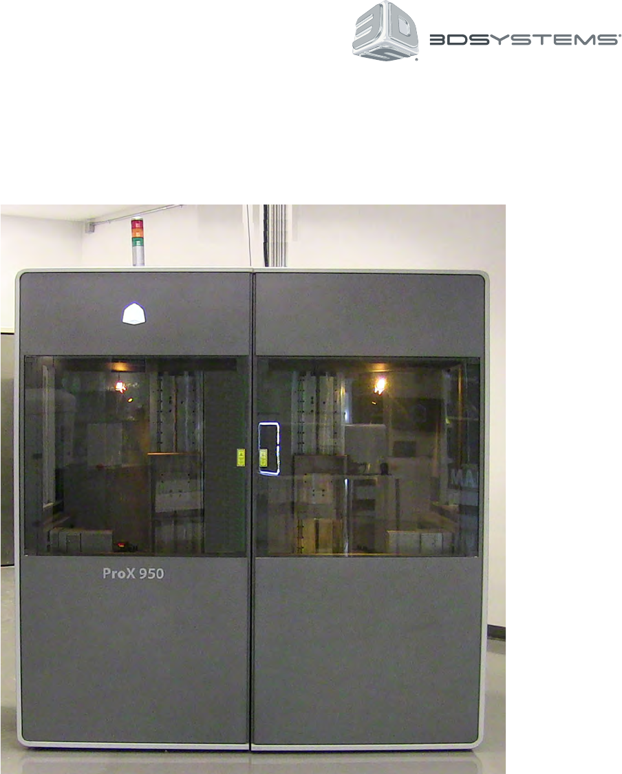
ProX™ 950
3D Printer System

3D Systems, Inc.
CONTENTS
INTRODUCTION TO THE PROX™ 950 .....................................................................5
WHAT’S INSIDE........................................................................................5
PRINTER FEATURES ...................................................................................5
ADDITIONAL DOCUMENTATION ..........................................................................5
SAFETY ..............................................................................................5
SYSTEM OPERATIONS..................................................................................5
SOFTWARE ...........................................................................................5
PRINT APPLICATOR SYSTEM ............................................................................5
SERVICE AND TROUBLESHOOTING ......................................................................5
GLOSSARY ...........................................................................................5
ProX 950 PRODUCTION PRINTER FEATURES ..............................................................6
MATERIAL DELIVERY MODULE ..........................................................................6
Print Mode ...............................................................................................6
Stand-by Mode............................................................................................6
MDM Capacity ............................................................................................6
Rell Container ...........................................................................................6
PRINT APPLICATOR ....................................................................................6
POLYRAY PRINTHEAD ..................................................................................6
ADDITIONAL DOCUMENTATION ..........................................................................7
ProX 950 FACILITY REQUIREMENTS GUIDE ................................................................7
ProX 950 INSTALLATION GUIDE ..........................................................................7
ProX 950 MATERIAL GUIDES ............................................................................7
ProX 950 QUICK START GUIDE...........................................................................7
ProX 950 MATERIAL SAFETY DATA SHEETS/SAFETY DATA SHEET (MSDS/SDS) .................................7
GENERAL SAFETY .....................................................................................8
HAZARD MESSAGES ...................................................................................8
LASER SAFETY........................................................................................9
CONTROL SWITCHES ..................................................................................9
Master Power Shut-off ......................................................................................9
Emergency Stop ..........................................................................................9
CONTROL PANEL LASER LED ...........................................................................9
SAFETY LABELS AND INTERLOCKS .....................................................................10
SAFETY WARNING LABELS ............................................................................10
CHEMICAL SAFETY ...................................................................................11
MATERIAL CHARACTERISTICS .........................................................................11
MATERIAL STORAGE..................................................................................11
1
2
3
4
5
6
7
8
2

3D Systems, Inc.
MATERIAL DISPOSAL .................................................................................11
MATERIAL SPILL CONTAINMENT ........................................................................11
FIRST AID AND PROTECTIVE EQUIPMENT ................................................................12
Skin Contact.............................................................................................12
Eye Contact .............................................................................................12
Contact Lenses ..........................................................................................12
Fume Inhalation ..........................................................................................12
ENVIRONMENTAL CONDITIONS .........................................................................12
TEMPERATURE.......................................................................................12
HUMIDITY AND ALTITUDE ..............................................................................12
SOUND PRESSURE ...................................................................................12
ProX 950 AT A GLANCE ................................................................................13
ProX 950 CENTER.....................................................................................13
SYSTEM COMPONENTS ...............................................................................14
User Interface ...........................................................................................14
Material Delivery Module (MDM) .............................................................................15
Electrical Cabinet.........................................................................................16
Manual Ofoad Cart.......................................................................................16
To Remove a Part ........................................................................................16
Setting the Ofoad Position .................................................................................17
SOFTWARE OVERVIEW ................................................................................18
HOME SCREEN .......................................................................................18
MANUAL PRINTER CONNECTION SCREEN ...............................................................19
STATUS SCREEN .....................................................................................20
PRINT QUEUE SCREEN ................................................................................21
PRINT HISTORY SCREEN ..............................................................................22
DETAIL POPUP SCREEN ...............................................................................23
MATERIAL STATUS SCREEN............................................................................24
TOOLS MENU SCREEN ................................................................................25
ELEVATOR/LEVELER SETTINGS SCREEN ................................................................26
PRINT APPLICATOR SCREEN ...........................................................................27
PRINTHEAD SETTINGS SCREEN ........................................................................28
NETWORK SETTINGS SCREEN .........................................................................29
HEATER SETTINGS SCREEN ...........................................................................30
DRAWING SETTINGS SCREEN ..........................................................................31
GLOBAL SCALE FACTOR SETTINGS SCREEN.............................................................32
SYSTEM OPERATIONS.................................................................................33
PRINTING A PRINT ....................................................................................33
9
10
11
12
3

3D Systems, Inc.
MANUAL OPERATIONS ................................................................................37
PRINT APPLICATOR INSTALLATION AND REMOVAL........................................................37
PRINT APPLICATOR CLEANING .........................................................................37
PRINT PLATFORM INSTALLATION .......................................................................38
PLATFORM REMOVAL .................................................................................38
MATERIAL DELIVERY MODULE (MDM) INSTALLATION ......................................................39
MDM REMOVAL.......................................................................................40
MATERIAL DELIVERY MODULE TEMPERATURE CONTROL ..................................................41
AUTO MATERIAL REFILL SYSTEM .......................................................................41
MATERIAL CONTAINER REMOVAL.......................................................................42
Release Lever ...........................................................................................42
Container Release Button ..................................................................................42
REPLACING MATERIAL CONTAINERS....................................................................43
TROUBLESHOOTING ..................................................................................44
POWER OUTAGES ....................................................................................44
ProX 950 CENTER SHUTDOWN..........................................................................44
ERROR SYMPTOMS AND OTHER PROBLEMS .............................................................44
CUSTOMER SUPPORT.................................................................................45
CUSTOMER SUPPORT HOTLINE ........................................................................45
SERVICE ............................................................................................45
GENERAL ...........................................................................................45
LASER ..............................................................................................45
UV Radiation ............................................................................................45
MAINTENANCE .......................................................................................46
DUST REMOVAL ......................................................................................46
PREVENTIVE MAINTENANCE ...........................................................................46
LEGAL NOTICES......................................................................................47
COPYRIGHT AND CORPORATE IDENTITY.................................................................47
IMPROVEMENTS......................................................................................47
FCC NOTICE .........................................................................................47
EC DECLARATION OF CONFORMITY.....................................................................48
GLOSSARY ..........................................................................................49
13
14
15
16
17
18
19
4

3D Systems, Inc.
WHAT’S INSIDE
INTRODUCTION TO THE ProX™ 950
The ProX™ 950 Stereolithography (SLA®) Production Printer
is equipped with 3D Systems’ newest PolyRay™ print head
technology that can manufacture real parts at up to 10 times the
speed of other 3D printers, drawing on the widest choice of proven
high-performance engineered materials that are qualied for the
most demanding aerospace, medical device and industrial use-
cases.
The ProX 950 is exible and versatile, and can produce precision
parts with accuracy that rivals CNC machining, ranging in sizes
smaller than the eye of a needle all the way to parts larger than a
life-size tiger without compromising feature details or true-to-CAD
accuracy.
With the industry’s widest array of SLA materials, the ProX
950 delivers a range of properties, from ABS-like toughness to
polycarbonate-like clarity. You can even cast directly from printed
patterns using QuickCast™ technology.
1
2
This manual includes the following topics:
PRINTER FEATURES
The ProX 950 Production Printer Features section gives an overview of the components of the ProX 950, such as the Material Delivery
Module, IPM (Image Print Module), Rell Container, Print Applicator, and Drawing System.
ADDITIONAL DOCUMENTATION
In the Additional Documentation section, you’ll nd a listing of many other documents related to the ProX 950, including the Facility
Requirements Guide and Material Safety Data Sheets.
SAFETY
General Safety, Laser Safety, Chemical Safety, and Environmental Conditions describe precautions that you should take when using
your new ProX 950 .
SYSTEM OPERATIONS
The System Operations section describes how to operate the ProX 950. The process of creating a print is covered in its entirety.
SOFTWARE
The Software Overview section gives you a detailed overview of the software that operates your ProX 950 .
PRINT APPLICATOR SYSTEM
Print Applicator System describes how to perform different operations with the manual delivery module (MDM).
SERVICE AND TROUBLESHOOTING
In Service and Troubleshooting, you will nd the troubleshooting guide and other basic information concerning service and maintenance
for your ProX 950 .
GLOSSARY
The Glossary denes terms that describe the ProX 950 and its operations. After the glossary, you will nd the Technical Specications
for your ProX 950.
5

3D Systems, Inc.
ProX 950 PRODUCTION PRINTER FEATURES
MATERIAL DELIVERY MODULE
The Material Delivery Module (MDM) is the device that manages all subsystems related to the print material including printing a part. It
can hold up to 935 liters (247 U.S. gal.) of print material. The maximum print volume is 1500 x 750 x 550 mm (59 x 29.5 x 21.7 in.) For
more information on the MDM see Material Delivery Module (MDM) on Page 15.
The MDM allows for quick material changes without any material waste/scrap. Not only can you now change material in less than ten
minutes, you can also swap the material delivery module (MDM) easily, with no tools required. All components that come into contact
with the material are moved with the module itself. One person can remove the MDM and replace it with another active MDM, without
having to clean any wet material surface. This new feature signicantly reduces material swap time. In addition, you can warm up an
MDM ofine, enabling you to swap one material delivery module for another that is ready to use.
This new handling method ensures that all parts that come into contact with the material during normal operation are a part of the active
MDM.
Nitrile gloves are required to detach the Zephyr™ print applicator, especially if there is any material left on the
applicator.
There are two operating modes for the MDM:
Print Mode
In this mode, the MDM is online and connected to the ProX 950 which provides the MDM’s power and Input/Output functionality. The
ProX 950 monitors and controls the material temperature while connected with the active MDM. When the MDM is online, it can pump
and recirculate material.
Stand-by Mode
In this mode, the MDM is ofine and operates independently from the ProX 950. When the MDM is plugged into a standard wall socket
the module self-regulates the temperature keeping it stable and at operating temperature. The material can warm effectively in this
mode, enabling the user to print a part while warming material for future use, allowing for no down time.
MDM Capacity
The ProX 950 is the largest commercially available 3D printer, the extra large material delivery module accommodates a print zone of
1500mm x 750mm x 550mm.
Rell Container
The ProX 950 rell containers incorporates smart cartridge technology that contains information about the material that is in the bottle
and the MDM. This information enables the ProX 950 to verify that the user does not use the wrong material, use material incorrectly, or
use an empty or expired containers, ensuring the material is safe to use.
PRINT APPLICATOR
The print applicator system either applies material to, or removes excess material from the part during the printing process as the
applicator moves across the material surface.
The print applicator system has a Zephyr™ applicator with four axes of motion: The y-axis moves the applicator from the front to
the rear. Other motion systems are utilized to ensure the exact amount of material is deposited, resulting in the high part accuracy
produced on this system. The applicator system’s liquid level sensor maps the material surface by moving around the material surface.
The sensor calibrates the position of the applicator so that it moves perfectly parallel to the material surface, enabling the print to be
accurate and precise. The applicator system uses the motion axes that are connected to the applicator, enabling the system to self-
calibrate and permitting a customized setting of the applicator gap, or distance from the applicator’s bottom to the material surface, for
different materials.
POLYRAY PRINTHEAD
The ProX 950 Polyray Printhead allows for the output of the largest parts quickly and accurately. It does this by operating and
seamlessly aligning two separate IPM’s (Image Print Modules) during the printing process. The IPM’s contain the UV light source,
drawing mirrors, power regulator and light source size congurator.
3
6

3D Systems, Inc.
ADDITIONAL DOCUMENTATION
The following documents will help you to achieve maximum prociency with your ProX 950 .
ProX 950 FACILITY REQUIREMENTS GUIDE
The Facility Requirements Guide details the requirements necessary to install the ProX 950 3D Printer. Details include the necessary
facility dimensions, electrical and pneumatic resources, and any equipment that may be needed for installation.
ProX 950 INSTALLATION GUIDE
The Installation Guide details the procedures required to properly install and set up the ProX 950 3D Printer at the customer’s site. Only
a 3D Systems Certied Field Service Engineer is allowed to install the printer.
ProX 950 MATERIAL GUIDES
The Material Guides detail the use of materials that have been certied for use in the ProX 950. Each material has its own Material
Guide. Information specic to each material is included in the guides.
ProX 950 QUICK START GUIDE
The Quick Start Guide gives the user a quick overview of the system and the procedure for printing and processing a part with the
ProX 950.
ProX 950 MATERIAL SAFETY DATA SHEETS/SAFETY DATA SHEETS (MSDS/SDS)
Each material has its own MSDS/SDS. The user must be familiar with all information contained in these documents before handling the
materials. Every material shipment includes a paper copy of its MSDS/SDS.
Electronic versions of the MSDS/SDSs are available on our website at http://www.3dsystems.com/support/materials/msds
4
7

3D Systems, Inc.
GENERAL SAFETY
HAZARD MESSAGES
The following symbols are used throughout this manual. Some also appear on the printer itself.
DAMAGE: Machine damage, part damage, and/or data loss can result if you ignore this type of hazard message.
ELECTRIC SHOCK: Injury or death from electric shock can result if you ignore this type of hazard message.
UV RADIATION: Eye injury or blindness can result if you ignore this type of hazard message.
IRRITANT: Bodily irritation or allergic reaction can result if you ignore this type of hazard message.
Wear gloves when handling uncured material.
Ultraviolet radiation inside. Exposure may cause eye damage. Do not operate without covers. Wear UV eye protection.
HOT SURFACE: Do not touch, may cause burn.
NOTE: Indicates an important point.
Always follow the safety procedures. Do not, in any way, risk injury by working dangerously. Safety is a part of work, and not an
obstacle to it.
The ProX 950 was designed with safety in mind; however, improper use and malfunctions can cause injury. To prevent unsafe
operation, the ProX 950 automatically shuts down immediately if it detects an unsafe condition.
Follow these general safety guidelines when operating your ProX 950 :
• Read and follow system instructions.
• Follow all safety rules in this section and heed all cautions and warnings in this guide.
• Do not attempt to open the chamber door or windows while a print is in process.
• Do not use any material without rst reviewing its Material Safety Data Sheet/Safety Data Sheet (MSDS/SDS).
• Secure the power and communication cables to prevent tripping.
• Do not attempt to access, service, or adjust the internal components.
• Do not attempt to perform any maintenance procedures unless you have been specically trained to do so.
• Operators are trained to operate the system and to perform all the necessary tasks to print a part.
• Certied service personnel have completed the 3D Systems service training package and are certied to perform service tasks.
Certication may occur at various levels and servicers should only perform tasks that they are authorized and certied to complete.
• Do not ignore warning signs that are posted during service operations.
• If you see an error message on the system’s display, refer to Troubleshooting on page 44 before resuming operation.
• To prevent potential skin irritation and sensitization due to contact with waste material, follow all guidelines in Chemical Safety on
page 11.
• To prevent pinch and crush injuries to the hand, use caution when replacing the platform inside the print chamber. The platform
carriage will not move when the chamber door is open.
5
8
3D Systems, Inc.
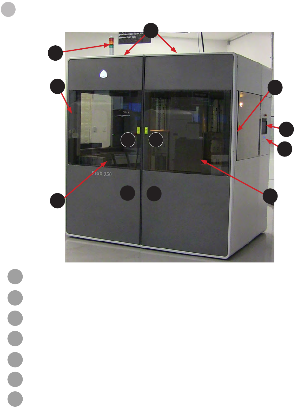
Master Power Shut-off
The ProX 950 has a master circuit breaker switch located on the electrical cabinet module at the
rear of the machine.
Emergency Stop
All ProX 950 printers have Emergency Stop buttons on the side panels and inside the print
chamber. They are bright red with a yellow background. Pressing one cuts power to all moving
axis, closes shutter, and puts laser in safe mode.
CAUTION: The Emergency Stop Button should be used when there is a fail situation
in the system. Use the emergency stop button when the system needs to be stopped
quickly.
LASER SAFETY
The ProX 950 uses a UV (Ultra-violet) solid-state frequency tripled Nd:YVO4 laser which utilizes a 354.7 nm wavelength laser in each
IPM.
The ProX 950 is a Class I Laser product. Class I products are not considered harmful and require no special safety precautions, under
normal operating conditions. The Laser beam is completely conned. The viewing windows in the Process Module, block the UV Laser
radiation from exposure outside of the print area(s).
RADIATION: Operating the equipment or performing procedures other than those specied within this guide may
result in exposure to hazardous, invisible Laser radiation.
RADIATION: Never stare directly into a Laser beam, nor into any beam reection, whether diffused or from a mirrorlike
surface.
RADIATION: During normal operation, and with all panels installed, the ProX 950 is classied as a Class I Laser
device. If any of the interlocks are defeated, the ProX 950 becomes a Class IV device. Eye damage can occur by
looking directly into the beam or by viewing any type of beam reection.
RADIATION: Interlocks are to be defeated only by trained personnel when needed during service procedures.
CONTROL SWITCHES
The locations of control switches are illustrated in the section, ProX 950 at a Glance on page 13. Master and Emergency power shut-
off switches are described in the following paragraphs.
6
CONTROL PANEL LASER LED
An LED light displays the current status of the Laser power availability at the Laser power supply.
9
3D Systems, Inc.
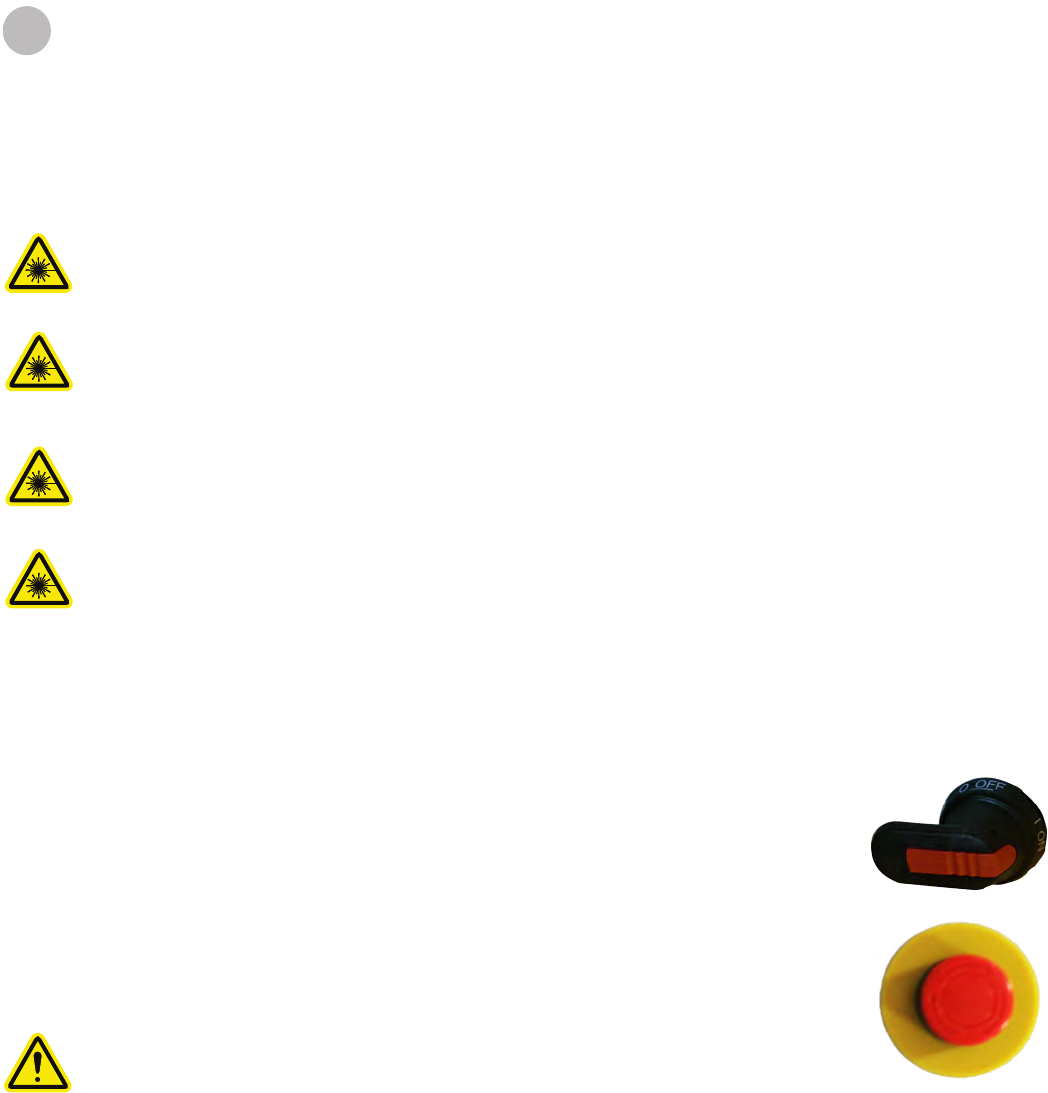
SAFETY LABELS AND INTERLOCKS
Laser safety labels are located at system entry locations which are indicated below. An interlock is located close to each label.
7
SAFETY WARNING LABELS
Laser safety warning labels for the ProX 950 are located at system entry locations which are indicated above.
SAFETY INTERLOCK SWITCHES
Safety interlock switches protect the user from possible UV Laser radiation exposure when certain doors or panels are opened. Safety
Interlocks are on the plate behind the safety warning labels.
10

3D Systems, Inc.
CHEMICAL SAFETY
IRRITANT! Always wear chemical-resistant gloves, goggles, and protective clothing when handling material. Avoid
skin contact. Avoid breathing material fumes.
• Always wear approved goggles, nitrile gloves and protective clothing when working near materials or with partially cured parts.
• Wearing contact lenses when working with materials is not recommended.
• Always wear chemical-resistant gloves whenever handling materials or partially cured parts. Recommended gloves are 100%
Nitrile. Latex gloves are not chemical-resistant and are not recommended.
• Always work in a well ventilated area when using materials. Avoid breathing vapors.
• Always wash skin thoroughly with abrasive soap and COLD water after working with materials. DO NOT USE HOT WATER OR
SOLVENTS to wash hands, as it will result in quick absorption through the skin.
• Use extreme care when handling solvents used to remove excess material from uncured parts. These solvents (e.g., denatured
alcohol, isopropyl alcohol) are very ammable.
• Keep all materials away from heat, sparks and ame. Material containers may rupture when exposed to extreme heat.
Use National Fire Protection Association Class B extinguishers such as carbon dioxide, dry chemical, or foam.
MATERIAL CHARACTERISTICS
The photopolymers used in stereolithography may be hazardous if handled improperly. Repeated skin contact with materials may
cause sensitization. Consult the manufacturer’s Material Safety Data Sheet/Safety Data Sheet (MSDS/SDS) for information on specic
materials. For further information on this and related topics, consult the 3D Systems – Materials website at http://www.3dsystems.com/
support/materials/msds
MATERIAL STORAGE
Material should be stored in opaque, non-reactive containers, according to the guidelines given in the MSDS/SDS included with the
material. Protect material from sunlight and ambient room light. Material may be stored in MDMs with the lid securely fastened.
Never mix different materials.
MATERIAL DISPOSAL
Do not dump used material down any drains. Follow disposal rules established by company, local, state, and federal authorities.
MATERIAL SPILL CONTAINMENT
Your company has the responsibility to dene what constitutes a major spill. Personnel who are involved in cleaning up major spills
of material should wear NIOSH/MSHA approved respirators designed for use with organic chemical vapors. In addition, each person
should wear protective goggles, rubber boots, and 100% nitrile gloves to minimize exposure to material, which can cause eye, skin, and
respiratory irritation, as well as possible skin allergies and respiratory reactions.
A supply of dikes and control booms should be stocked so they are available to contain the affected area in the event of a major material
spill. The spilled material should then be absorbed on inert absorbent material and placed into drums for transfer to an approved waste
disposal site. After cleaning up the spill, individuals should wash thoroughly with soap and COLD water. Dry-clean contaminated clothing.
Discard contaminated shoes and leather products. Avoid exposure to sunlight until skin and clothing have been cleaned of material. Refer
to the MSDS/SDS before using any chemicals. Repeated or prolonged skin contact may cause sensitization. Vapor may be harmful.
8
11

3D Systems, Inc.
FIRST AID AND PROTECTIVE EQUIPMENT
The following paragraphs provide general rst aid procedures and recommendations for protective equipment to minimize the risks from
material exposure. If professional medical attention is necessary, take the Material Safety Data Sheet/Safety Data Sheet (MSDS/SDS)
for the exact material involved to the attending physician.
Skin Contact
Wear 100% nitrile gloves and lab coats to avoid skin contact. Should material come in contact with skin, wash thoroughly with soap and
cold water and immediately remove contaminated clothing and shoes. If skin is irritated, seek medical attention. Dry-clean contaminated
clothing. Discard contaminated shoes and leather products.
Eye Contact
Safety goggles should be worn to prevent accidental splashes into the eyes. If material comes in contact with the eye, ush immediately
with large amounts of water for 15 minutes, avoid sunlight, uorescent light, and other ultraviolet light, and obtain immediate medical
attention. Eye wash facilities and a rst aid kit should be readily available and close to the material.
Contact Lenses
If material splashes into the eye when contact lenses are worn, ush the eye with water immediately. Verify that ushing has removed
the contact lens from the eye. Protect eyes from light and obtain immediate medical attention. Discard contact lenses that come into
contact with liquid material.
Fume Inhalation
Remove the person to fresh air. Give articial respiration or cardiopulmonary resuscitation (CPR) if required. If breathing is difcult, give
oxygen. Obtain immediate medical attention.
ENVIRONMENTAL CONDITIONS
TEMPERATURE
To allow optimum systems operation and optimum part quality, the temperature of the ProX 950 System’s room or other location should
remain stable. The working range is 23°C +/- 3°C (73°F +/- 5°F). Any temperature uctuation greater than 3°C may adversely affect
parts built on the system.
The air conditioning system should maintain a temperature change of less than 1°C per hour. The stereolithography room should have
a minimum cooling capacity of 1.4 kW. We recommend an HVAC system that changes the air two to ve times per hour. To avoid
adversely affecting part quality, do not expose the ProX 950 system to direct air ow from the air conditioning system.
Beyond the temperature range that is optimum for part quality, the system is capable of operating safely without creating a hazard
between 5°C and 40°C.
HUMIDITY AND ALTITUDE
The optimum humidity in the ProX 950 print chamber depends partly on the material selection, although humidity should always be
non-condensing and should not vary outside the range of 20-50% for optimum part quality with most materials. The system can operate
at higher non-condensing humidity levels but may adversely affect part quality. Review your ProX 950 material information, MSDS/SDS,
product datasheet, and product labeling, for specic information on recommended humidity levels. The ProX 950 can operate correctly
up to an altitude of 1000m above mean sea level.
SOUND PRESSURE
Overall sound pressure level for this equipment will not exceed 70 dBA.
9
12
3D Systems, Inc.
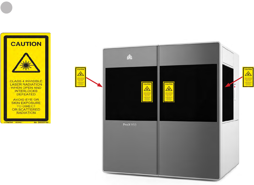
ProX 950 AT A GLANCE
10
Polyray Printhead : The ProX 950 contains two IPMs. The IPM’s are located at both sides on the top of the machine,
beneath the frame panels.
User Interface (UI): This is the control touchscreen which allows the user to interface with the the system. The Print3D Pro
software installed on the touchscreen enables the user to view and adjust the print parameters used to print a part.
System Status Lights: System Status Lights indicate critical information regarding the system. See the section, LED
Indicators on page 14 for descriptions of each indicator.
Print Zone A: Print Zone A is located on the left side of the ProX 950, as you face the machine, and is utilized for the printing
of all machine congurations up to 30” wide.
Print Zone B: Print Zone B is located on the right side of the ProX 950, as you face the machine, and is utilized only for print
sizes over 30”. If the print is over 30” it will be centered between the two zones.
Door Handle Locations: To open the doors, pull them by the handle-like grips at the edge of the door panel.
Light Stack: The light stack consists of three lights, red, yellow and green. The lights reect what state the machine is in at
any given time.
ProX 950 CENTER
A
B
C
D
E
F
G
13
A
F
DE
C
F
F F
F
F
B
G
3D Systems, Inc.
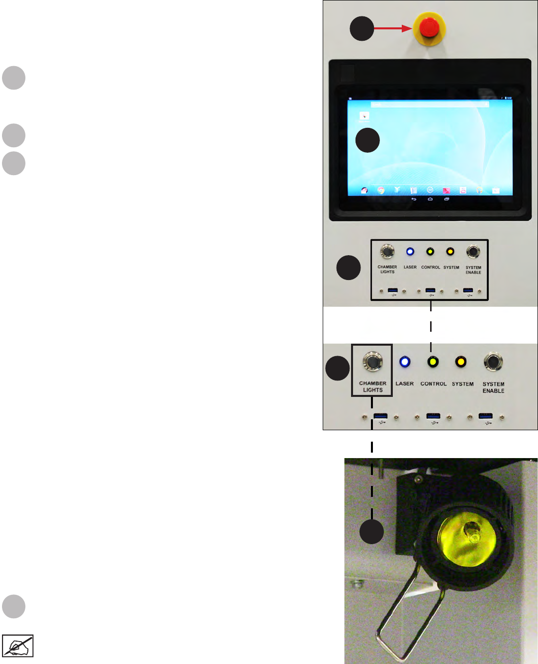
Emergency Stop: This switch is located on side panel above
the touch screen. Emergency Stop immediately disables all
motion controls and Lasers and renders them safe. After being
pressed, it remains in the closed state until it is manually
returned to the open state.
Touchscreen: Displays the Print3D Pro software which is
used to operate the system.
Buttons, Indicators, USB Ports
LED Indicators: The LED indicators indicate the readiness of
the machine and its Lasers.
• “Laser” Blue LED
- ON, Solid
»Printhead enabled
- OFF
»Printhead disabled or off.
• “Control” Green LED
-ON, Solid
»Control systems are enabled. The machine is ready
for use.
-ON, Flashing
»Machine is in BYPASS mode.
-OFF
»Control systems are not enabled. The machine is not
ready for use.
• “System” Amber LED
-ON, Solid
»All safety and interlock systems have been satised.
Laser safety shutter is operational.
-OFF
»All safety and interlock systems have not been
satised. Laser safety shutter is not operational.
System Enable: Once the software has been launched,
user will press the System Enable button to lock the doors
so system is ready to print a build. Use System Enable
after someone has pushed the emergency stop, when the
emergency has been cleared and user wants to resume
building.
USB: Three standard auxiliary USB ports connected to the
control PC are be located under User Interface.
Chamber Lights: This switch turns the chamber lighting
on or off.
Note: The chamber lights can be repositioned to view
specic areas as needed. Check the switch on the lights
themselves if they do not come on when you press the
button under the user interface.
A
B
C
SYSTEM COMPONENTS
For system requirements, consult the Facility Requirements Guide.
C
User Interface
The User Interface consists of a touchscreen located on the side of
the printer and the system status LED indicators. An E-Stop is located
above the touchscreen. See the section, Software Overview on page
18 for descriptions of the touchscreen functionality.
B
D
A
D
B
C
D
D
14
3D Systems, Inc.
Material Delivery Module (MDM)
Rell Containers 1 and 2: These containers hold the bottles of new material, which are added to the MDM prior to the start of
a print. The rell containers incorporates smart cartridge technology that contains information about the material that is in the
bottle and the MDM. This information enables the ProX 950 to verify that the user does not use the wrong material, use
material incorrectly, or use an empty or expired containers, ensuring the material is safe to use.
Applicator Rest: This rest area is used to stow the removable applicator when changing MDMs.
Leveling Reservoir: This reservoir is used to store material for transferring into or out of the print area to maintain the precise
material height during printing.
Fill Pumps: The ll pumps control the material height in the print area by moving material to or from the leveling reservoir.
MDM Heater Power Switch: In the On position, the MDM will regulate material temperature. In the Off position temperature
regulation doesn’t occur. This functions in both Standby and Print modes.
I/O Connector: This connector is the interface for all communication and motion control between the MDM and the ProX 950.
Serial Connector: There is a serial connector on the right side and one on the left side of the MDM. The left side Serial
Connector connects the Smart Cartridge Technology reader for bottle on the left, and creates communication of the heater
to the vat. The right side Serial Connector controls the Smart Cartridge Technology to the bottle on the right side.
Heater Connector: This connector plugs the heater into the MDM allowing the material to heat. When in Print mode this is
connected to the machine, when in Standby mode this is connected to the wall.
A
B
C
D
E
F
G
H
15
FD
B
D
E
A C A
GHF
G
3D Systems, Inc. 16
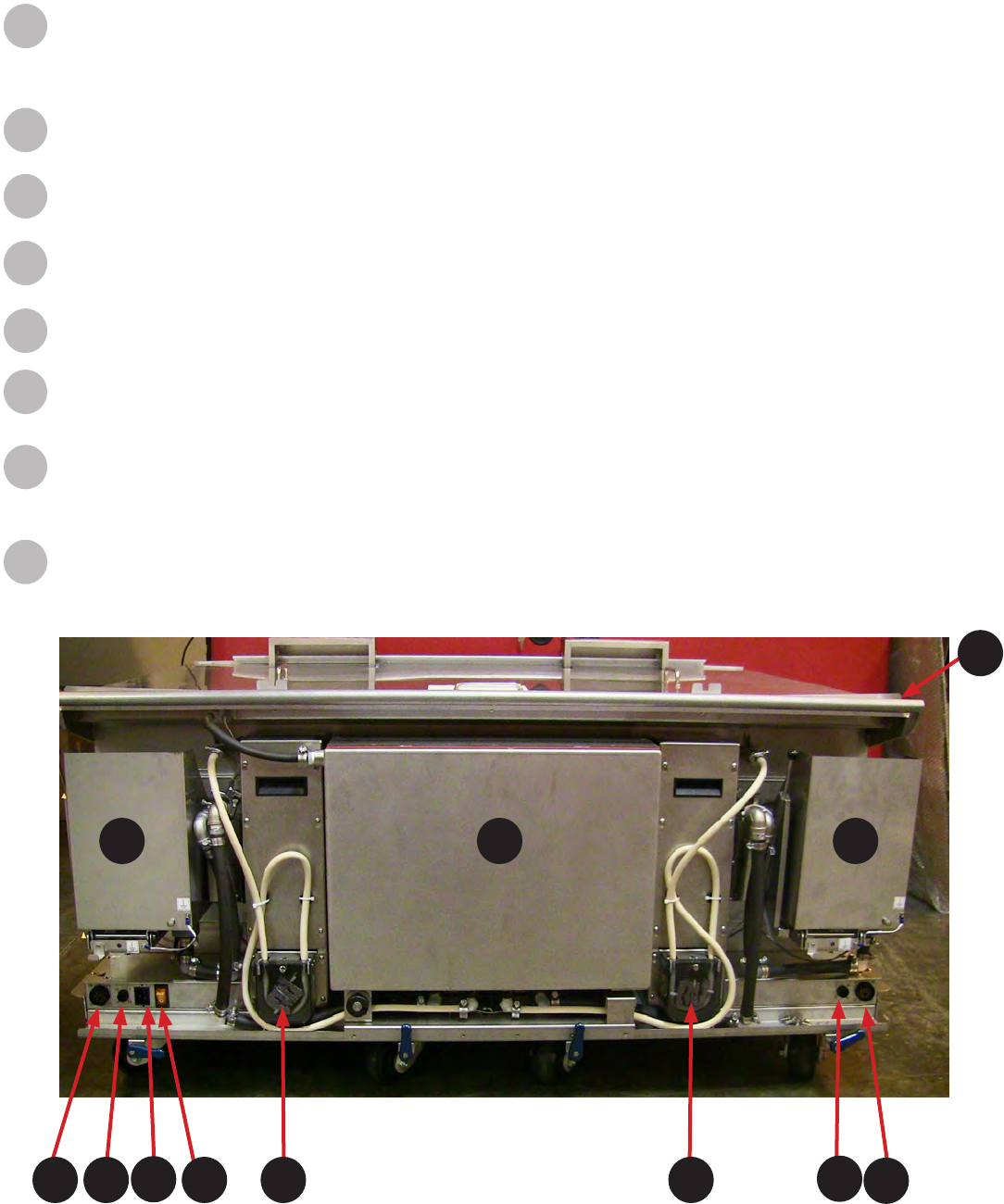
Electrical Cabinet
Main Power Disconnect: The disconnect enables you to turn off all power to the system. For
safety reasons, the machine should be positioned to allow easy access to this switch. This is the
switch that needs to be enabled to turn the system on as well.
Computer: A computer which controls the printer is located inside the electrical cabinet. The user does not have direct access to this
device. The touchscreen user interface provides all user functionality.
Reset Button: Reset Home recalibrates the home positions of the left and right side. If the left and right side motors of the recoater
blade get out of synch you would need to reset. You would be able to tell if the blade is askew.
Power Supply: This module distributes all the AC power that the system needs. Circuits for the various subsystems are located in this
module.
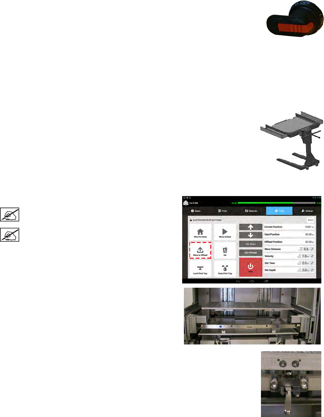
Manual Ofoad Cart
The manual ofoad cart is included in the base conguration of the ProX 950. The
ofoad cart allows you to easily remove the print platform when it is loaded with a
large or heavy part and transport it to the nishing area where supports are removed
and the part is cleaned before it is cured.
All parts must be ofoaded with the manual ofoad cart to ensure optimal safety.
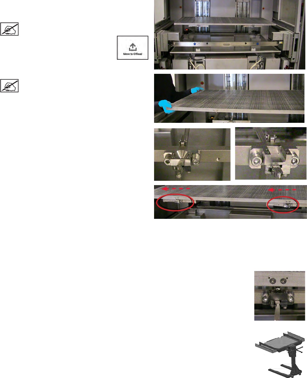
To Remove a Part
1. Navigate to Tools > Elevator/Leveler Settings click on Move to
Ofoad. This will move recoater down 2” and platform up.
NOTE: the Move to Ofoad settings are already set in the
software. If additional changes need to be made, follow
steps in Set Ofoad Position.
NOTE: Always wear nitrile gloves when removing the
platform. If any build material gets on skin, wash skin
immediately with soap and water.
2. Ensure there is enough room to slide ofoad cart under platform
without touching tabs on recoater.
3. Unlatch platform from forks by pulling latch handles toward you.
4. Slide Manual Ofoad Cart under platform.
5. Using handles on cart carefully pull platform out of machine.
3D Systems, Inc. 17
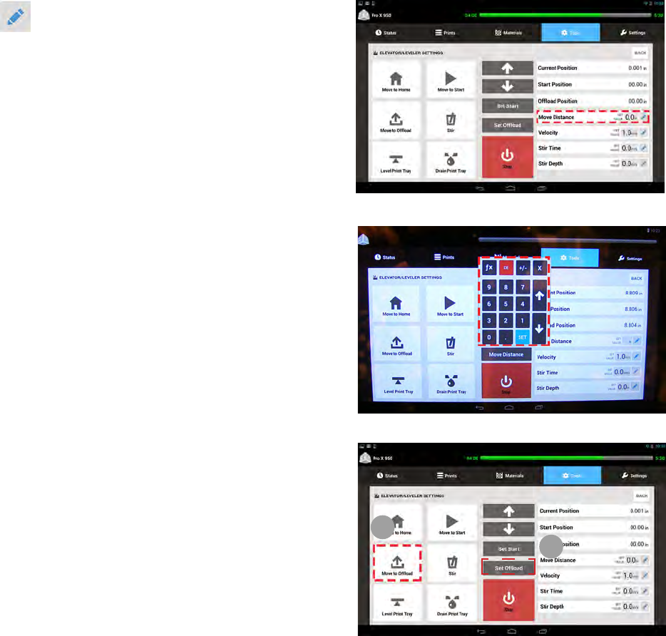
Setting the Ofoad Position
If the Manual Ofoad needs to be adjusted you can do so by following these steps:
1. Select Edit from Move Distance.
2. Editing keypad pops up. Type in amount to move (ex. .5 will move
platform up 1/2 inch), this is a good place to start.
3. Click Set
4. Repeat these steps until platform is far enough up to get Manual
Ofoad Cart under it without damaging recoater.
NOTE: If platform is too high you can reverse it by typing
.5 > - > Set in the editing keypad. This moves platform
down 1/2 inch.
5. Select Set Ofoad (1).
6. Repeat Steps 3-5 of To Remove a Part.
NOTE: This position will now be saved and can be used
from now on by selecting Move to Ofoad (2).
1
2
3D Systems, Inc.
SOFTWARE OVERVIEW
The touchscreen of the ProX 950 uses Google’s Android operating system, running the 3D Systems’ Print3D Pro™ application.
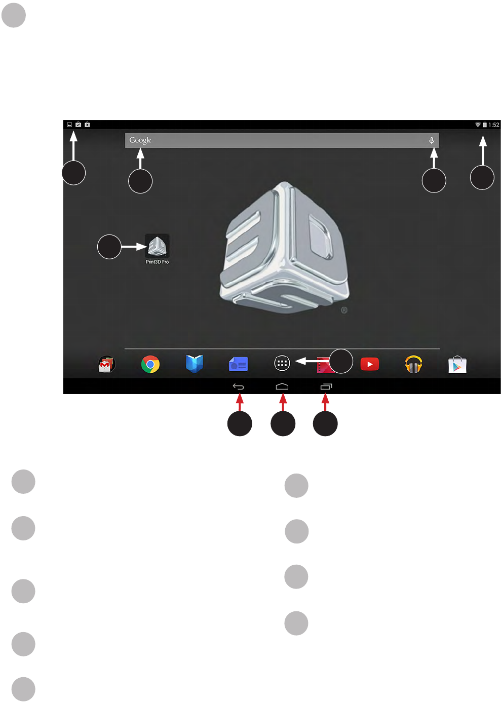
HOME SCREEN
When tablet is powered on, there should be a 3D Print Pro icon (A) displayed. Tap the icon to launch 3D Print Pro. If icon is not
present, tap the Home button (C) and select 3D Print Pro from the apps displayed.
11
18
A
GHI
F
E
B C D
Print3D Pro™ Application Icon: Press this icon to launch
the Print3D Pro application.
Back: Opens the previous screen you were working in,
even if it was in a different application (app). Once you
back up to the Home screen, you can’t go back any further
in your history.
Home: Opens Home. If you’re viewing a left or right Home
screen, opens the central Home screen. To open Google
Now, swipe up.
Recent Apps: Opens a list of thumbnail images of apps
you’ve worked with recently. To open an app, touch it. To
remove a thumbnail from the list, swipe it left or right.
All Apps: View all of the applications on the device.
A
B
C
D
E
Alerts and Notications: Alerts and messages occur
within the annunciator bar. When alerts are tapped they
direct the user to a popup notication.
Google Search Bar: Open Google’s search engine.
Voice Input: Press to activate voice-to-text input.
Status Icons: Bluetooth, Wi-Fi, & battery status
F
G
H
I
3D Systems, Inc.
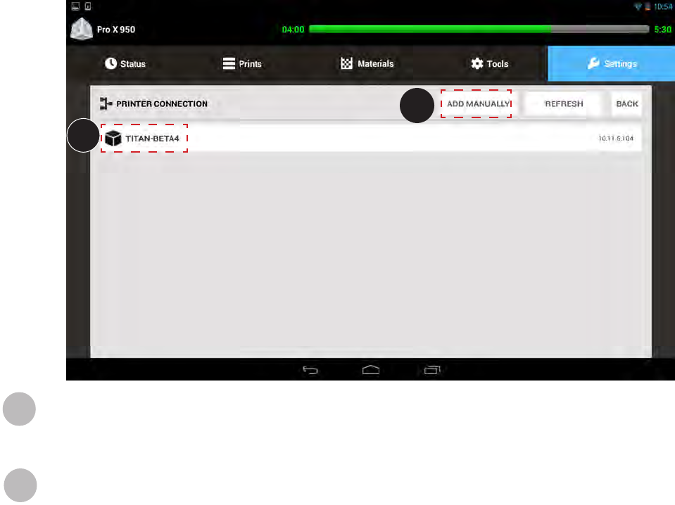
MANUAL PRINTER CONNECTION SCREEN
Your printer should already be networked correctly, in which case you will not see this screen. If it becomes necessary to set the
network connection up manually, the Settings tab will appear after you launch the Print3D Pro application.
Press the ADD MANUALLY button. You will be prompted to enter the IP address for your printer. The address will vary,
depending on your setup. If you do not know your address, contact your systems administrator.
Enter the correct address into the eld and press ADD.
Your printer will appear in the list. Press the name of the printer to continue launching Print3D Pro
A
B
19
A
B
3D Systems, Inc.
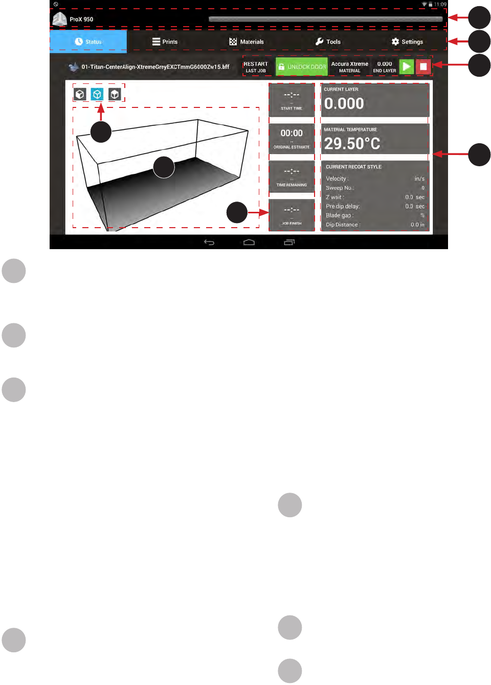
STATUS SCREEN
The Status screen displays important real-time information about the printer. This screen is mainly used for information purposes other
than the Navigation Bar (B), and the Overview Bar (C).
Status Bar: The status bar displays the printer name,
alerts/notications, and print progress with time elapsed
(left side number) and estimated time remaining (right side
number). The bar changes color and displays urgent alerts
and print errors.
Navigation Bar: The top navigation bar consists of ve
distinct tabs: Status, Prints, Materials, Tools, and Settings.
Select any of these tabs to open up a new screen and
navigate through selected item.
Overview Bar: From this bar, the user can view the
progress and relevant status indicators for the current job.
Restart: When Restart is pressed will issue a start
job command with the restart ag. The machine
knows which was the last running job.
If the machine is able to restart the last job (from the
last printed layer) then the machine will go in building
state. However, if it is not able to restart, machine
will issue a build aborted notication which will be
displayed as a pop up on the tablet UI.
Unlock Door: Pressing this button will toggle the
doors between Lock and Unlock positions.
Material: Indicates the material that is currently being
used by the system.
End Layer: Indicates what the last layer of the print
is.
Start/Stop: To stop or start the current printing job,
press the appropriate button. You will be presented
with a conrmation screen to verify your choice.
Current Settings: This section displays various
parameters of the current print job. These are the values
programmed using the application software.
Current Layer: The end value of the layer currently
being printed.
A
B
C
D
Material Temperature: Temperature (in °C) of the
material in the print tray.
Current Recoat Style:
Velocity: Speed in inches/second of the print
applicator mechanisim.
Sweep No.: Number of sweeps performed.
Z wait: The delay time between the print
applicator sweep and the point at which the Laser
begins to draw
Pre dip delay: The amount of time between
when the Laser has nished drawing and when
the elevator motion and applicator process
begins.
Blade gap: Percentage of distance between the
applicator blade and the material surface during
the applicator process.
Dip distance: Distance that the elevator moves
down during the applicator process.
Print Job Timing: These elds display the following
information:
Start Time: Time the print job began.
Original Estimate: Estimated time to complete the
print job, calculated using the initial settings.
Time Remaining: Estimated remaining amount of time
until the print job is completed.
Job Finish: Actual time when the print job is projected
to nish.
View Port: A preview of the 3D model which is being
printed appears in this window.
Preset Views: The 3D model has 3 preset views. From
left to right, they are: front, isometric, and top.
E
F
G
F
C
D
G
A
B
E
20
3D Systems, Inc.
AD
E
CB
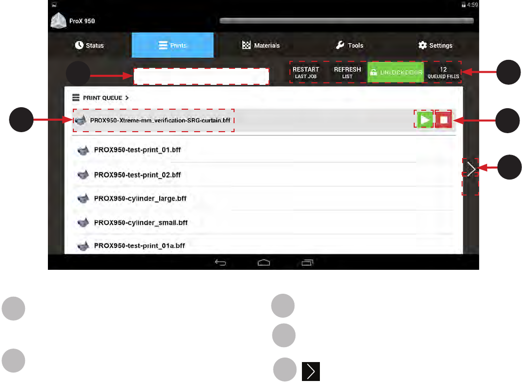
PRINT QUEUE SCREEN
The Print Queue screen displays the current jobs waiting to be processed.
Print Job File Name: File that is currently the next to
print appears here with a gray background. All the other
les in the queue appear below.
Print Queue Statuses: These elds display:
Restart: When Restart is pressed will issue a start job
command with the restart ag. The machine knows
which was the last running job.
If the machine is able to restart the last job (from the
last printed layer) then the machine will go in building
state. However, if it is not able to restart, machine
will issue a build aborted notication which will be
displayed as a pop up on the tablet UI.
Refresh: Refresh is to refresh the queue list on the
tablet. If a user submits a job from the thumb drive
while in the queue menu he would need to refresh
the list on the tablet. Or he can exit the queue and
go back it will automatically refresh the list.
Unlock Door: Pressing this button will toggle the
doors between Lock and Unlock positions.
Queued Files: Number of les currently in the
queue.
A
B
Search: Use the search bar to quickly nd a print job
Start/Stop: Use these buttons to start or stop the print.
Next Page: Navigate to the Print History screen,
described below.
E
D
C
21
3D Systems, Inc.
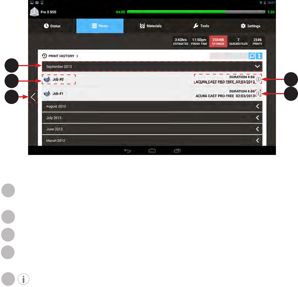
PRINT HISTORY SCREEN
The Print History screen gives the user access to information and functions related to previous print jobs.
Folder (by month): The print history is sorted and grouped by month. Press anywhere on the black bar to see a list of the
print jobs for that month. When the white arrow is pointing towards the left the folder is closed, when arrow is pointing down
folder is open. Toggle back and forth between open and closed by selecting anywhere in the black bar for the month.
Print Job: The specic print job is listed under the month.
Back: Navigate back to the Print Queue screen, described above.
Print Job Information: Information about the job is listed here such as the duration of the print job, material, and date are
listed here.
Information: Press the information icon to bring up a dialog box which gives you the choice to Copy to Queue which
will copy the chosen job to the active print queue, or Delete which will remove the print job from the Print History.
A
B
C
D
E
A
B
C
D
E
22
3D Systems, Inc.
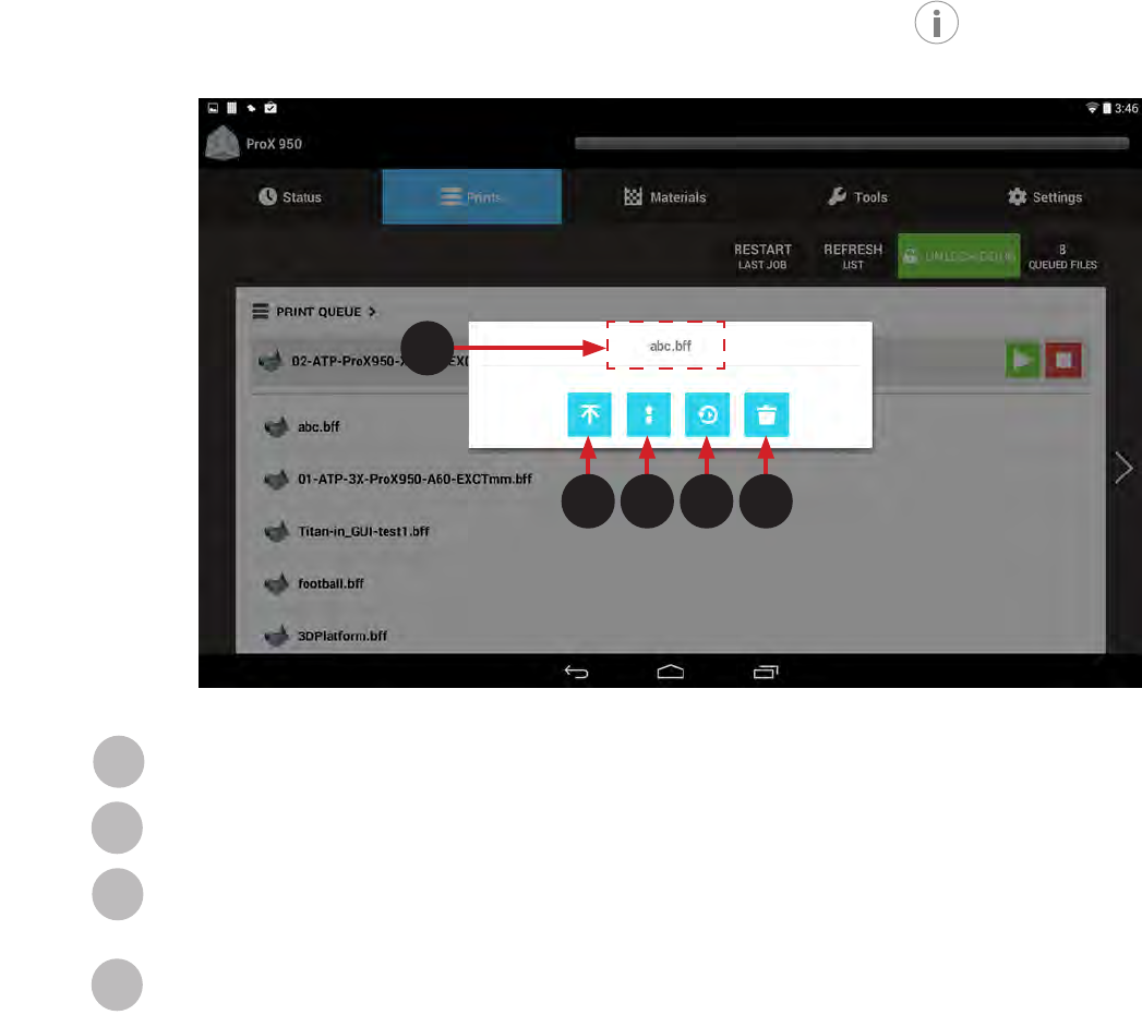
DETAIL POPUP SCREEN
This screen provides additional actions that a user can perform to a le. It is displayed when the button is pressed on the Print
Queue Screen.
B
A
C D E
Move to Top of Queue: Move the current job to the top of the print queue.
Move Up/Down in Queue: Move the current job up or down in the print queue.
Move to Print History Select this button to move to the Print history. If currently in the print history, selecting this will take you
back to the Print Queue.
Delete: Delete the job from the print queue.Selecting this button after selecting the desired job, will move it to the trash.
B
B
C
D
E
23
3D Systems, Inc.
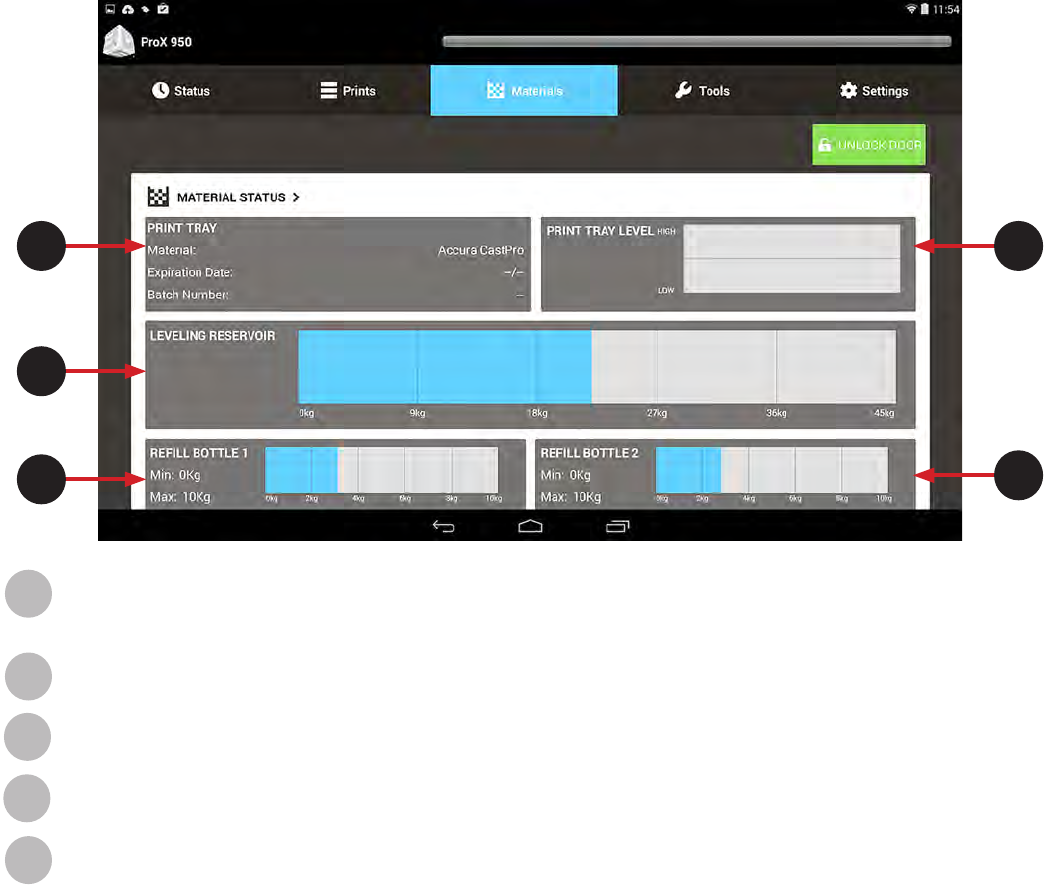
MATERIAL STATUS SCREEN
The Material Status Screen displays information pertinent to the material in the system.
A
B
CD
E
Print Tray: This eld provides information on the current material type, expiration date of that material, and batch number of
the material in the print tray.
Leveling Reservoir: Displays the weight of the material in the MDM.
Rell Bottle 1: Displays the weight of the material in rell bottle 1.
Rell Bottle 2: Displays the weight of the material in rell bottle 2.
Print Tray Level: Indicates the amount of material in the print tray. Line indicates the nominal level of material.
A
B
C
D
E
24
3D Systems, Inc.
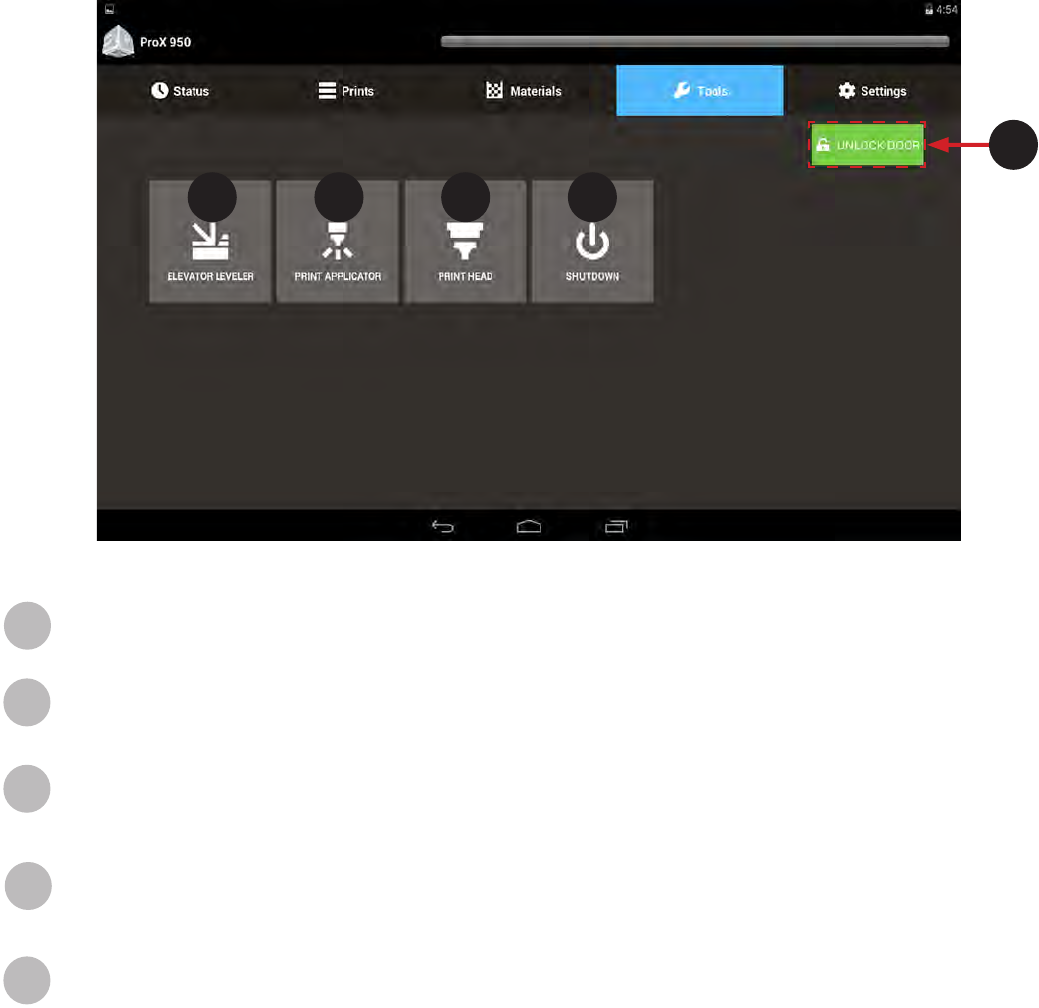
TOOLS MENU SCREEN
The Tools Menu Screen allows the user to navigate to various manual operations menus which are described below.
A
Unlock Door: Pressing this button will toggle the doors between Lock and Unlock positions.
Elevator Leveler: This tool allows user to operate the elevator/leveler manually. See Elevator/Leveler Settings on next page
for more detailed usage.
Print Applicator: The Print Applicator Screen allows you to operate the applicator manually. For more detailed usage see
Page 26 for information.
Printhead: The Printhead Screen gives the user access to functionality of the Printhead. Settings on this screen are only
applicable to the IPM which is selected. The “A” IPM is on the left side of the machine (while the user is facing the print
chamber doors) and the “B” IPM is on the right side. See Page 27 for more information.
Shutdown: This feature shuts down the printer.
A
B C D E
B
C
D
E
25
3D Systems, Inc.
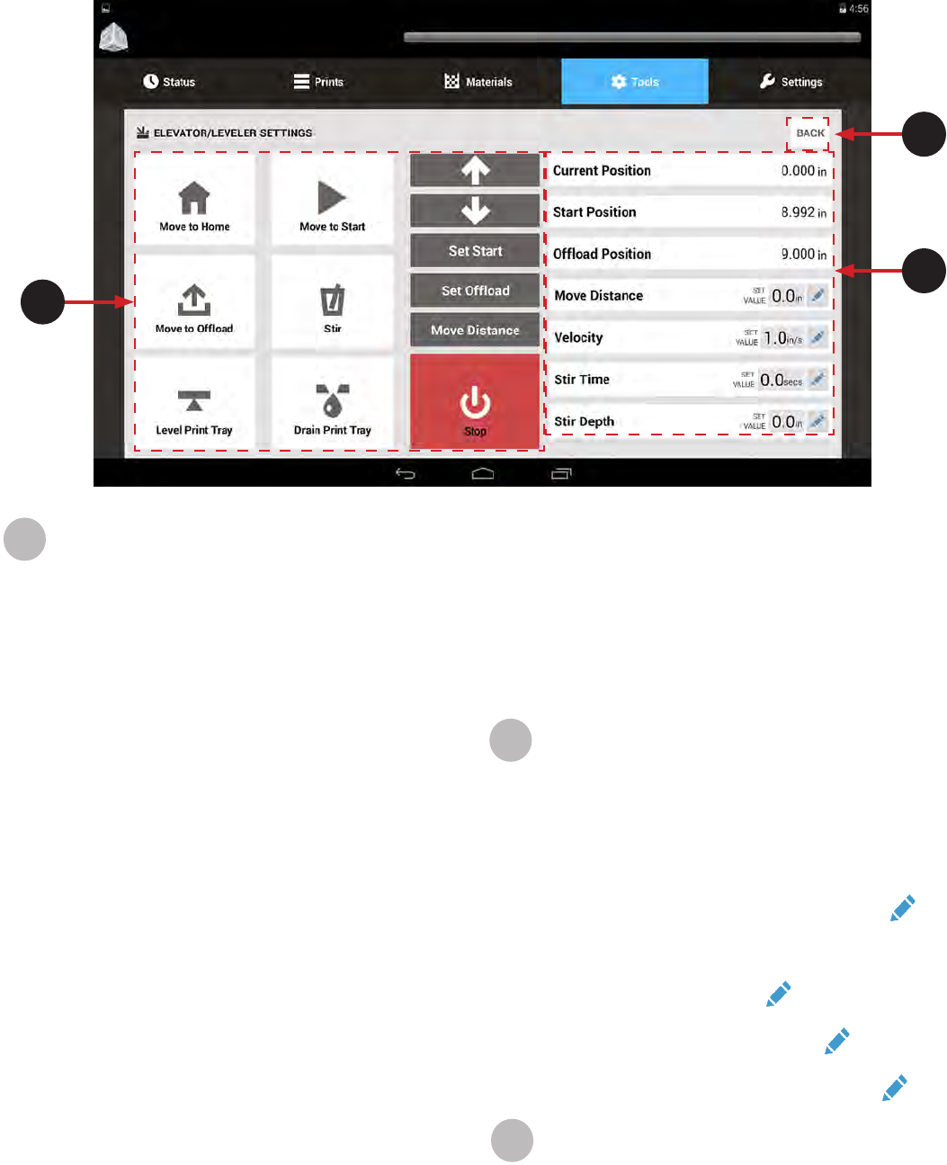
ELEVATOR/LEVELER SETTINGS SCREEN
The Elevator/Leveler Settings Screen allows you to operate the elevator manually.
Manual Motions:
Move to Home: Move the elevator to its home
position.
Move to Start: Move the elevator to its start position,
as dened in its Set Start settings.
Move to Ofoad: Move the elevator to its print
ofoad position as dened in the Set Ofoad
settings.
Stir: Pressing this button causes the system to mix
the material by moving the elevator up and down
according to the settings entered. Perform the
following steps:
1. Using the up and down arrows, position the
elevator to the uppermost stir position.
2. Set the Move Distance value for the distance to
lower the elevator.
3. Set the Stir Time for the amount of time to
perform the stir action.
4. Press Stir.
Level Print Tray: Pumps material into and out of the
leveling reservoir until the material is level.
Drain Print Tray: This button drains print tray until
the leveling reservoir is full.
Up/Down Arrows: Manual motion for the elevator.
Press and hold until the elevator moves in the
direction of the arrow, will keep moving until it
reaches its limit.
Set Start: Saves the elevator’s current position as
the Start position. See Printing a Part for instructions
on setting the Set Start position.
A
AB
C
Set Ofoad: Saves the elevator’s current position as
the Print Ofoad position. The ofoad position comes
pre-set in the software, however, some adjustments
made need to be made. If the Move to Ofoad button
needs to be adjusted follow the steps in Setting the
Ofoad Position found earlier in this manual. .
Move Distance: Allows you to move elevator a
dened distance.
Stop: Stop the current motion.
Parameters:
Current Position: Shows the current position of the
elevator relative to the home position.
Start Position: Displays the elevator’s start position.
Ofoad Position: Displays the setting elevator’s
ofoad position.
Move Distance: Amount to manually move the
elevator. Set this value using the edit button
Velocity: Species the elevator speed, in inches per
second, during manual motion. This setting does not
affect the applicator speed during printing. Set this
value using the edit button
Stir Time: Amount of time to perform the stir function.
Set this value using the edit button
Stir Depth: Distance to lower the elevator when
stirring. Set this value using the edit button
Back: Navigate back to the Tools Menu Screen.
B
C
26
3D Systems, Inc.
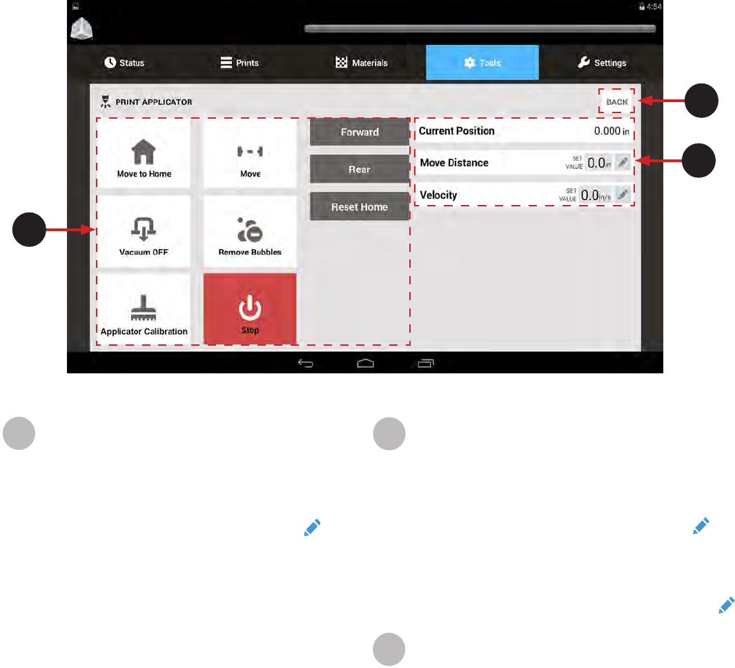
PRINT APPLICATOR SCREEN
The Print Applicator Screen allows you to operate the applicator manually.
A
B
C
Manual Motions:
Move to Home: Move the print applicator to its home
position.
Move: To manually move the print applicator:
• Set the Move Distance and Velocity to the
desired value by using the edit button.
• When these values are satisfactory, press the
Move button to activate manual motion.
Vacuum OFF: Switch the print applicator vacuum on
and off.
Remove Bubbles: Runs a predened operation to
remove bubbles on the material surface.
Applicator Calibration: Runs a predened operation
to calibrate the print applicator system.
Stop: Stops the current manual motion and
operation.
Forward: Manually move the print applicator towards
the front of the system. Press and hold to move.
Rear: Manually move the print applicator to the rear.
Press and hold to move.
Reset Home: This recalibrates the home positions of
the left and right sides. This will need to be used if the
left and right side motors of the print applicator blade
get out of synch.
AParameters:
Current Position: Shows the current position of the
print applicator relative to the home position.
Move Distance: Amount to manually move the print
applicator. Set this value using the edit button
Velocity: Species the print applicator speed, in
inches per second, during manual motion. This
setting does not affect the applicator speed
during printing. Set this value using the edit button
Back: Navigate back to the Tools Menu Screen.
C
B
27
3D Systems, Inc.
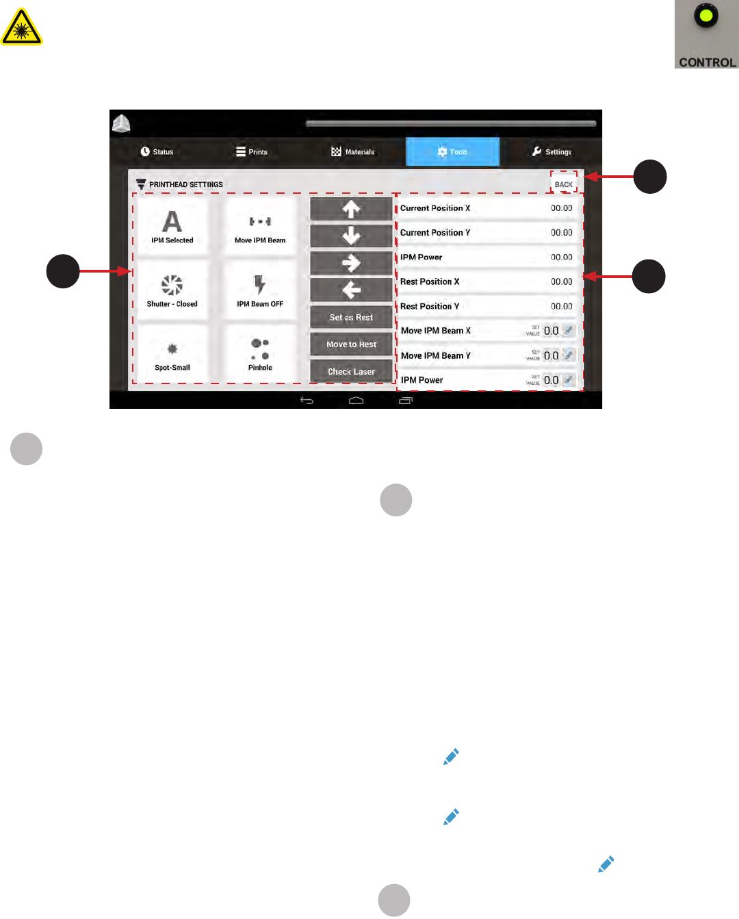
PRINTHEAD SETTINGS SCREEN
The Printhead Settings Screen gives the user access to functionality of the IPM. Settings on this screen are only applicable to the IPM
which is selected. The “A” IPM is on the left side of the machine (while the user is facing the print chamber doors) and the “B” IPM is on
the right side.
WARNING: CHECK TO ENSURE THE IPM GREEN CONTROL LAMP IS ON AND NOT FLASHING PRIOR TO
PERFORMING ANY OF THESE PROCEDURES. REFER TO THE USER INTERFACE SECTION OF THIS
MANUAL FOR DETAILED INFORMATION. CONTACT FIELD SERVICE IF THE GREEN CONTROL LAMP IS
FLASHING. PERFORMING ANY PROCEDURES WITH THE IPM IN THE FLASHING STATE COULD CAUSE
EXPOSURE TO HAZARDOUS RADIATION.
AB
C
Manual Motions:
IPM Selected: Choose which IPM (A = left side,
B = right side) will be affected by the settings.
Move IPM Beam: To manually move the IPM Output
Beam:
• Set the Move IPM Beam X and Move IPM Beam
Y elds to the desired values.
• When these values are satisfactory, press the
Move IPM Beam button to activate manual
motion.
• Use the Arrow Keys to control the motion.
Shutter - Closed/Open: Switch the IPM Beam shutter
between open and closed.
IPM Beam ON/OFF: Allows you to manually turn
the Laser on or off. When you start a build the laser
automatically turns on.
Spot-Small/Large: Toggles the IPM Beam spot size
between large and small.
Pinhole: Opens Proling Mode. In this mode the
beam will check the position of the pinhole to ensure
the build is buidling in the proper spot. This works as a
checkpoint to ensure the build is starting and building
at the same starting point.
Up/Down/Left/Right Arrows: Manual motion control
for the IPM Beam.
Set as Rest: Set the current IPM Beam position as the
rest position.
Move to Rest: Move the IPM Beam to the stored rest
position.
ACheck Power: Checks the IPM power and returns a
value based on the IPM power setting.
Parameters:
Current Position X: Shows the current x-axis
position of the IPM Beam relative to the home
position.
Current Position Y: Shows the current y-axis position
of the IPM Beam relative to the home position.
IPM Power (Current Setting): Displays the current
requested IPM power.
Rest Position X: Shows the current x-axis rest
position of the IPM Beam relative to the home
position.
Rest Position Y: Shows the current y-axis rest
position of the IPM Beam relative to the home
position.
Move IPM Beam X: Set the value to manually adjust
the IPM Beam along the x-axis using the edit button.
To move the IPM Beam, use the Move IPM Beam
Arrows.
Move IPM Beam Y: Set the value to manually adjust
the IPM Beam along the y-axis using the edit button.
To move the IPM Beam, use the Move IPM Beam
Arrows.
IPM Beam Power (Set Value): Set the IPM Beam
power using the edit button.
Back: Navigate back to the Tools Menu Screen.
C
B
28
3D Systems, Inc.
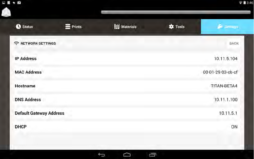
NETWORK SETTINGS SCREEN
The Network Settings Screen allows the user to view the values related to the system network.
IP Address: View the IP address for the system.
MAC Address: View the MAC Address for the system.
Hostname: View the network host name of the system.
DNS Address: View the main TCP/IP address for the DNS Server.
Default Gateway Address: View the TCP/IP address for the Default Gateway.
DHCP: Switch the Dynamic Host Conguration Protocol (DHCP) on or off.
29
3D Systems, Inc.
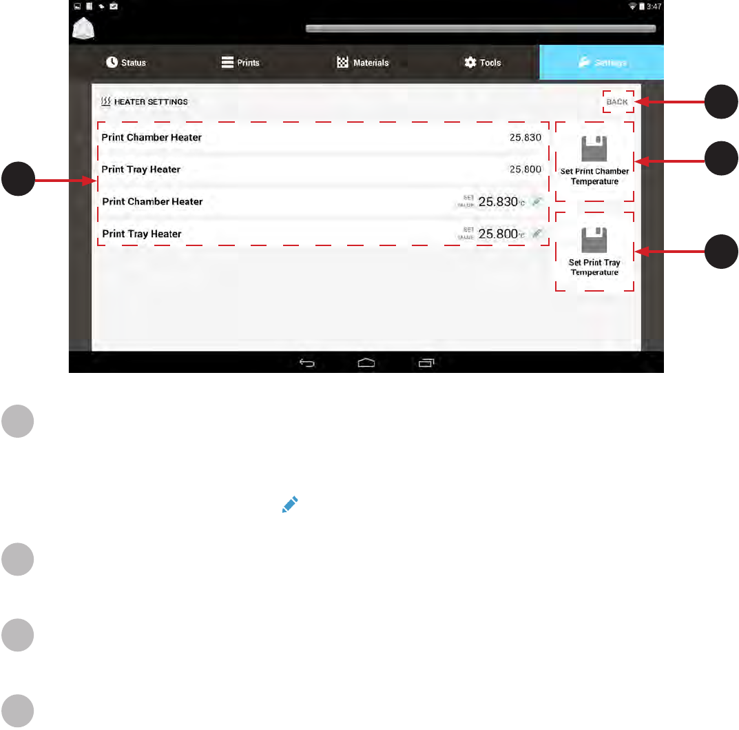
HEATER SETTINGS SCREEN
The Heater Settings screen allows the user to view and set parameters of the system heaters.
Print Chamber Heater: View the current temperature for the chamber heater.
Print Tray Heater: View the current temperature for the print tray heater.
Print Chamber Heater: View the current temperature for the chamber heater.
Print Tray Heater: View the current temperature for the print tray heater.
For any eld that you need to set press the key to edit.
Back: Use this to navigate to previous screen.
Set Print Chamber Temperature: Saves settings of the Print Chamber Temperature
Set Print Tray Temperature: Saves settings of the Print Tray Temperature.
A
B
C
D
A
B
C
D
30
3D Systems, Inc.
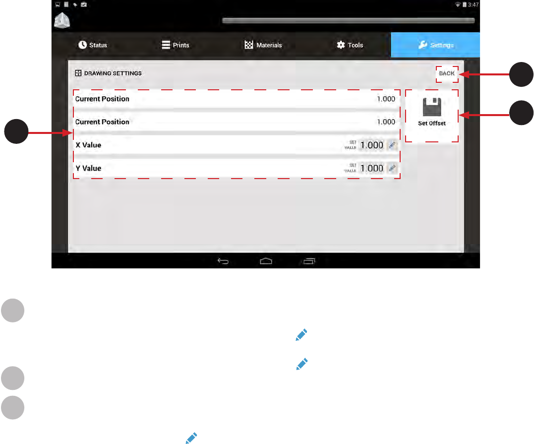
DRAWING SETTINGS SCREEN
The Drawing Settings Screen allows the user to view and set the distance parameters of the drawing platform. This shifts the entire
extents of the imaging system by the amount indicated. The image is automatically centered in the middle of the platform. If the user
wants to shift for one reason or another they can do sy by editing the X and Y values.
Current Position: Displays the current X Position.
Current Position: Displays the current Y Position.
X Value: This is where the current X Value can be edited. Select key to edit. This will shift the entire extents of the imaging
system by the amount indicated.
Y Value: This is where the current Y Value can be edited. Select key to edit.
Back: Use this to navigate to previous screen.
Set Offset: Saves the current Offset values.
For any eld that is editable press the key to edit.
A
B
C
A
B
C
31
3D Systems, Inc.
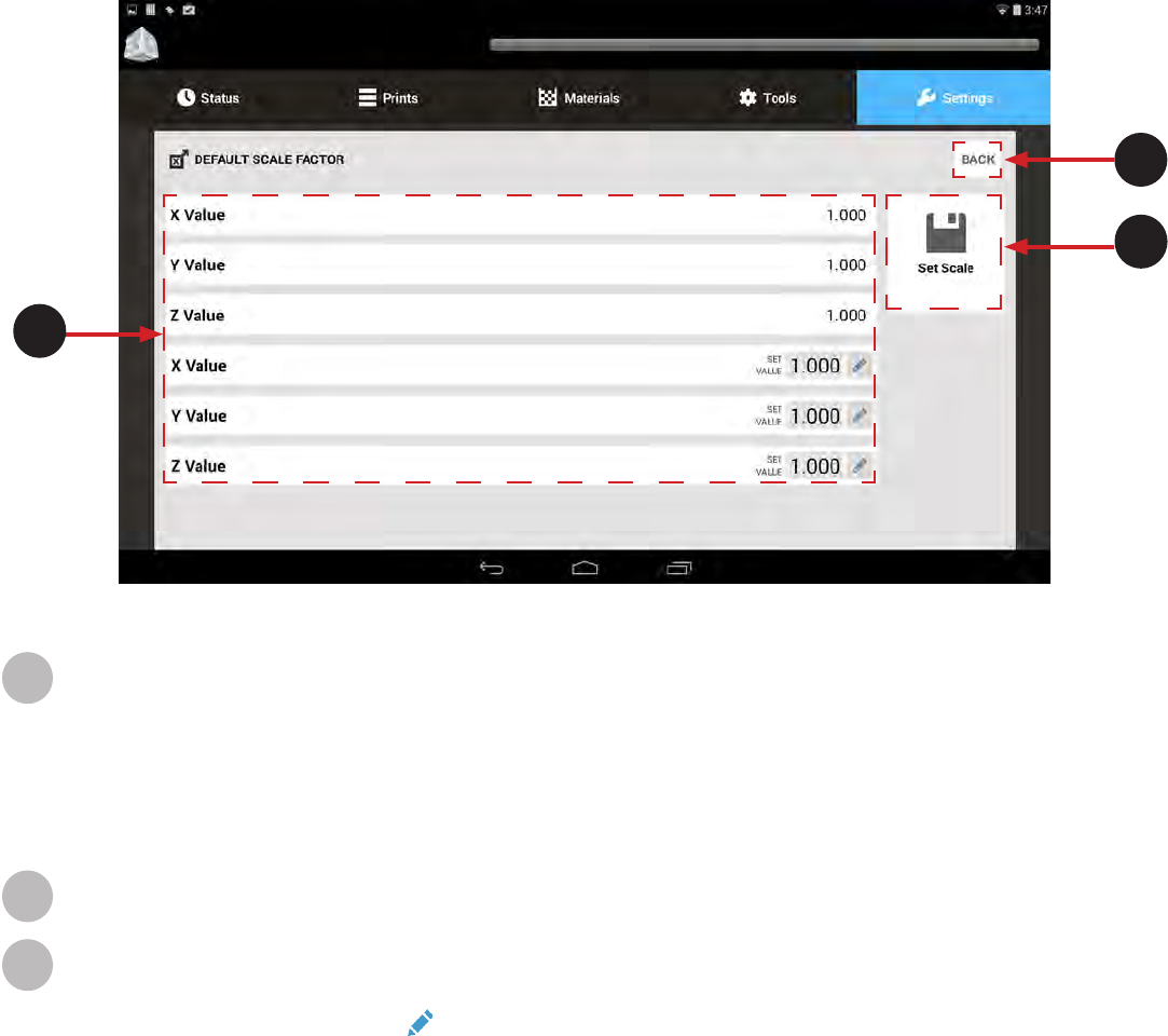
GLOBAL SCALE FACTOR SETTINGS SCREEN
Scale factors are very important for part accuracy. Each machine and resin require different scale factors to build accurate parts.
Typically users will build a series of precision parts and measure them with calipers or a measurement system. If there are errors, either
too large or too small, they will enter scale factors to adjust for the errors and repeat the process until the error is zero or small enough
to not affect quality of the part.
X Value: View the current x-axis scale factor.
Y Value: View the current y-axis scale factor.
Z Value: View the current z-axis scale factor.
X Value: Edit the current x-axis scale factor.
Y Value: Edit the current y-axis scale factor.
Z Value: Edit the current z-axis scale factor.
Back: Use this to navigate to previous screen.
Set Scale: Saves the Scale settings.
For any eld that is editable press the key to edit.
A
B
C
A
B
C
32
3D Systems, Inc.
SYSTEM OPERATIONS
PRINTING A PRINT
Now that you are familiar with the various screens within the User Interface, you can now print your rst print. Follow these basic steps
to print your rst part.
NOTE: Ensure print platform is installed prior to printing a part. See Print Platform Installation Page 36 for more
information.
12
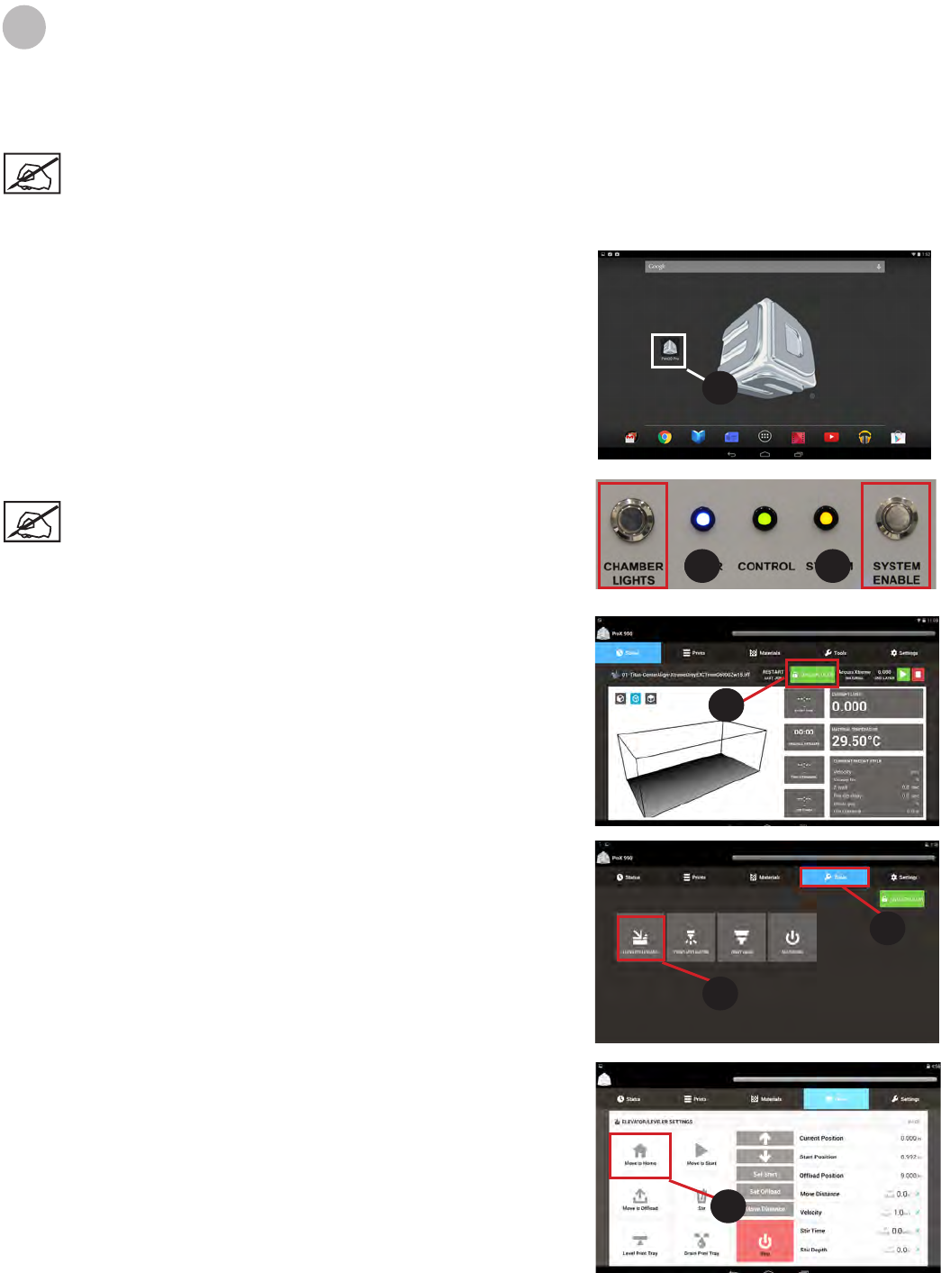
1. Turn machine on by turning the disconnect switch located at the
back of the machine clockwise until it is in the ON position.
2. Select Print 3D Pro from the tablet home screen(1).
3. Turn chamber lights on (1)
NOTE: This is optional, machine will build without
chamber lights on.
4. Ensure all doors are locked by verifying the System (1) light is lit.
If it is not, press the System Enable (2) button.
5. Verify the doors are locked by looking at the UI. The green lock
button should show Unlock Door if doors are locked. If not, press
this button to lock doors (3).
Home the elevator
1. Select Tools from main screen (4).
2. Select Elevator/Leveler (5).
3. If machine was not already turned on, select Move to Home (3). If
machine has been on and used, this step is unnecessary. Continue
to next page.
1
1 2
3
4
5
6
33
3D Systems, Inc.
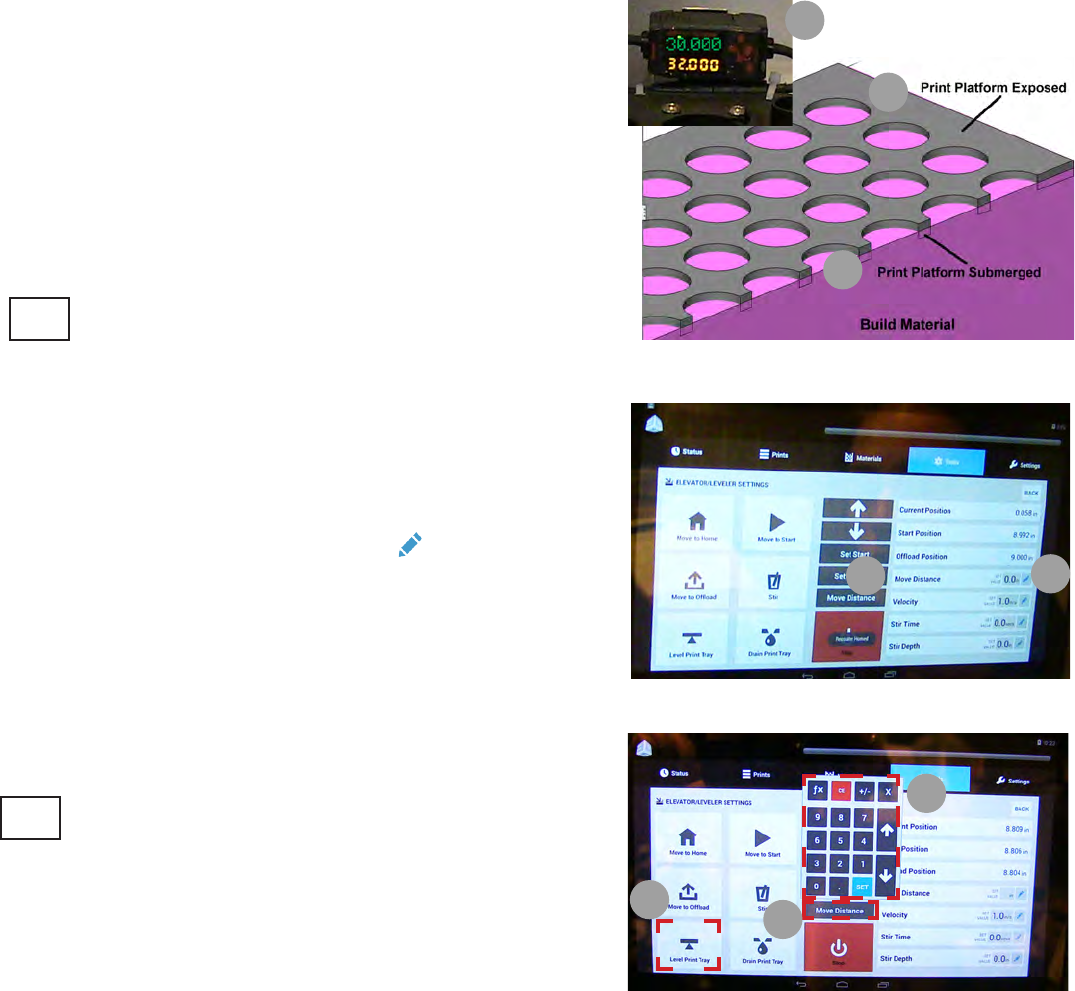
Setting the Build Start Position
The Build Start Position is the position of the platform when the machine
is set up for optimal build success. The Build Start Position will need to be
set either when it’s the rst time the machine has built anything or any of
the three conditions below are not met:
a. Top of platform must be exposed
b. Bottom of platform must be submerged
c. The Omron Sensor must be reading 30.000
If any one of these conditions are not met, after Move to Home is
selected, the Build Start Position must be set.
NOTE: You should be able to see the entire platform including
all the holes. If any holes are completely submerged and can’t
be seen, the Build Start Position needs to be set.
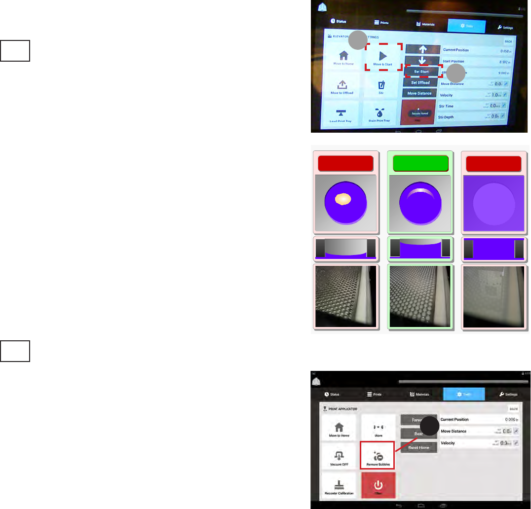
To Set the Build Start Position:
1. Select Move to Home. Wait for elevator to home.
2. Select Move to Start: The elevator will move to the default Build Start
Position.
3. In the Move Distance (1) menu, select Edit (2).
4. Type in the value you wish to move the platform, for example,
.1 > Set (3).
NOTE: If at any time platform needs to be moved in the other
direction you can move it in a negative motion by entering in
the number Value (.1) > - > Set. This will move platform down
instead of up.
5. Select the Move Distance Button (4) from the middle of the screen
above the Stop button. Continue to move the elevator until conditions a.
and b. are met.
6. When Platform meets conditions a. and b. stated in the steps above,
Select Level Print Tray (5).
7. Ensure that all three conditions are still met:
a. Top of platform is exposed with no material spilling out over
platform.
b. Bottom is submerged
c. Omron Sensor is reading 30.000.
If not, repeat Steps 5-6 until these conditions are met.
a
b
c
3
4
5
12
34
3D Systems, Inc.
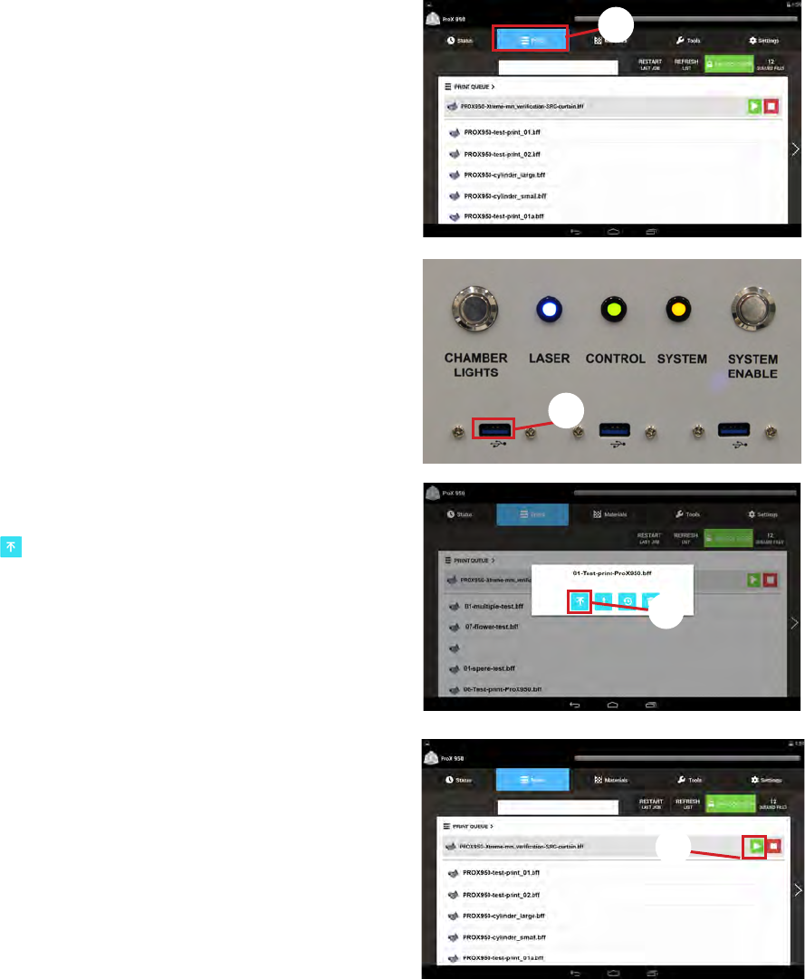
Once the platform meets conditions a.b. and c., you must set the Build
Start Position before building. At this time select Set Start (6) button from
the middle panel.
NOTE: If the Build Start Position is not set, the elevator will
move to the original default Start Position during build.
Anytime the platform is removed and re-inserted it is advised that Move to
Start (7) be selected and the print tray leveled to check and make sure that
all settings have been retained and platform is in optimal building mode. If
not, you will need to repeat Steps 1-7 to reset your Build Start Position.
The graphic on the right shows what a correct build start position should
look like. Use this as a standard to go by. Once the build start position is set
check for bubbles in the material. See Removing Bubbles for procedure.
NOTE: After setting the Build Start Position, there may be bubbles in the print tray. Bubbles must be removed before
building. To remove bubbles follow Removing Bubbles from next page.
Removing Bubbles
If bubbles appear in material, they must be removed prior to starting a print.
Follow these steps to remove bubbles:
4. Navigate to the Tools menu.
5. Select Remove Bubbles (1).
6. Wait while bubbles are removed.
7. When recoater returns to home position print can be started.
6
7
Too High Too Low
Just Right
1
35
3D Systems, Inc.
7. Tap the Play button next to the .bff le desired to print, or wait for
the le print to pop up in the top left corner and then tap the Play
button (5).
8. Wait for the machine to fully print the rst layer to ensure that
the print has successfully started. You can see which layer the
machine is printing by looking at the UI.
Printing a Part
1. Select the Prints menu (2).
2. Insert USB drive into the port below the touch screen (3). Files can
also be transferred from the application software - Option 1 or 2.
3. All .bff les on drive will pop up on screen. Select le you wish to
print.
4. Tap the Submit button.
5. The le selected should be loaded in the prints queue.
6. If le is not in the top position, tap the le to highlight it, then tap
the Jump to Top button to move the le to the top of the queue
(4).
3
2
4
5
36
3D Systems, Inc.
MANUAL OPERATIONS
PRINT APPLICATOR INSTALLATION AND REMOVAL
The print applicator is on a rail system above the material delivery module (MDM). The applicator process combines elevator and
applicator movements to apply material to the top of the part so that the next layer can be built. The applicator, which contacts the
material, can be removed from the ProX 950. The applicator should be kept with the MDM so that when the material is changed, the
applicator remains with the material that it has been in contact with.
Note: applicator tabs are delicate. Extra care should be taken to prevent damage to them. If tabs are damaged, the
applicator calibration process will not perform properly, resulting in print failures.
13
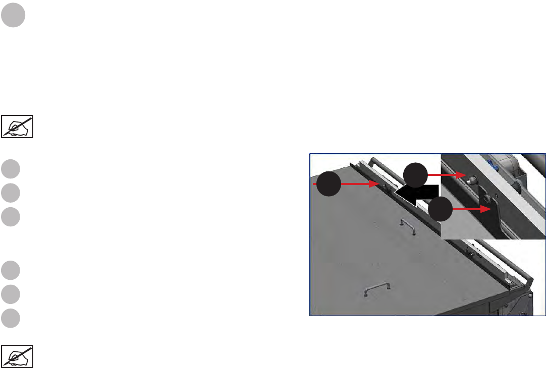
To install the applicator, do the following:
Take applicator off of the applicator rest that is on the MDM.
Place the applicator onto the two locating pins.
Secure applicator with the thumb screws which are present.
To remove the applicator, do the reverse of above:
Loosen the thumb screws.
Remove the applicator from the two locating pins.
Place applicator onto the applicator rest located on the MDM.
1
2
3
1
2
3
1
2
3
PRINT APPLICATOR CLEANING
The print applicator will need to be cleaned periodically. Remove the print applicator, wipe print applicator off with a paper towel with
some isopropyl alcohol. Be careful not to get any isopropyl alcohol in the material in the MDM. Be sure to wear nitrile gloves when
handling print applicator.
Note: During printing, if the print completes or stops, or if the applicator stalls, the applicator automatically moves
back to the home position.
37
3D Systems, Inc.
PRINT PLATFORM INSTALLATION
Verify the MDM is installed in the machine before starting this process. When correctly installed, the print platform sits on the elevator
platform mount. This procedure was done without the MDM installed for clarity only. Always install print pad with MDM in place. Wear
nitrile gloves when handling the print platform to prevent material exposre to your skin.
1. Verify elevator is at its ofoad position by moving elevator to
the ofoad position by selecting the Manual Ofoad button
on the Elevator/Leveler screen under the Tools menu.
NOTE: L-Shaped Guides are shown with platform
already on it, for this step the platform is not
normally installed.
2. Place the platform onto the L-shaped guides in the rear of
the MDM.
NOTE: This step requires two people to place the
platform on the guides safely, unless using the help
of the ofoad cart. If using the ofoad cart, this can
be done by one person.
3. Push the platform against the front platform guides. The left
guide has a circular bowl shape for the ball of the platform to
sit on and the right side has a notch.
4. Make sure that the notches in the platform engage with the
front platform guides. Once platform is sitting in notches of
guides, move the levers in front of the guides to the left to
lock platform in place.
5. Platform is now installed.
PLATFORM REMOVAL
After the print is complete, select Drain Platform from the Elevator/Leveler Screen. This function raises the elevator forks up out
of the MDM. After allowing sufcient time for part to drain (about 30 minutes), using nitrile gloves, follow these steps to remove the
platform from the elevator forks.
1. Flip the levers in on the forks to the right until they are both point towards you.
2. Move the manual ofoad cart 2 into position so it can slide under the print platform. Once the
cart is in place, raise the cart up by rotating the bar on the ofoad cart so cart raises up, lock in
position. Carefully wheel cart out of machine and proceed with the next step of preparing your
part for use.
Left Right
38
3D Systems, Inc.
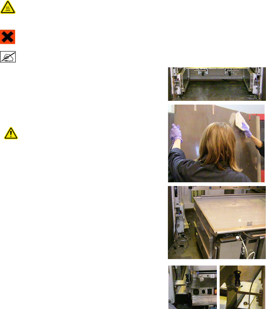
MATERIAL DELIVERY MODULE (MDM) INSTALLATION
The MDM is made of stainless steel and has eight casters for moving and maneuvering it while installing or removing it from the
machine. There are also handles on the MDM that help the user to transport and maneuver it into and out of the system.
HOT SURFACE: The area underneath the MDM where the heaters are located is hot (about 40°C (104°F)) —Do not
reach underneath!
Make sure that the elevator is at its lower limit by rst homing the print applicator, homing the elevator and then moving the
elevator down -10. You must also ensure that the print applicator is in its storage location on the MDM. Assuming the MDM is outside
the ProX 950, the following steps describe how to install it.
IRRITANT!: While performing this procedure, wear protective clothing, disposable nitrile gloves, and goggles.
Note: Move the MDM very slowly. Sudden starts and stops can result in material spills, even with the MDM lid in
place. Continuous slow movement is important.
1. Make sure that the connecting cables are out of the way before you attempt
to place the MDM into the machine.
2. Wearing nitrile gloves, remove the cover from the MDM, wipe off any excess
material from inside the lid by carefully applying some isopropyl alcohol to a
paper towel and wiping excess material off of cover. When nished, store lid
in a safe place.
CAUTION: Ensure no alcohol gets spilled into material. Alcohol will
contaminate material causing it to build ineffectively.
3. Open the front doors of the ProX 950 and slowly roll the MDM into the
machine.
4. Roll the MDM until the locking pins located on the inside of the ProX 950
are lined up with the brackets on the MDM. Turn the pins until they set into
the brackets. The left side of the bracket has a hole for the pin to set into. The
bracket on the right has a notch. When the locking pin attaches properly, the
MDM will also hit the bumper at the back of the machine.
39
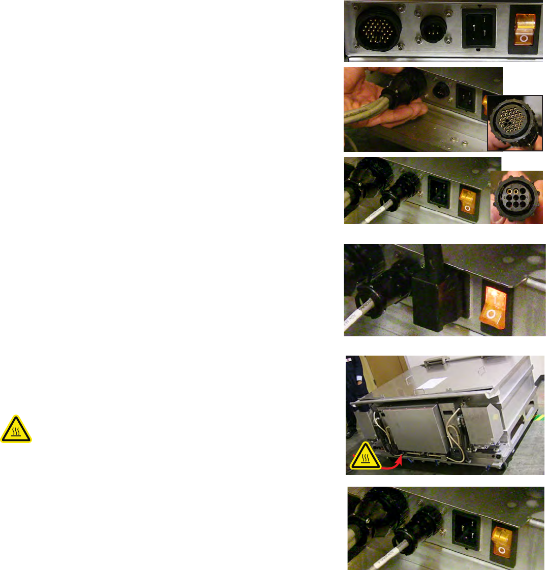
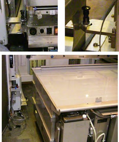
3D Systems, Inc.
5. Once the MDM is in the machine, connect the cables in the front of the MDM
as shown.
6. Plug in the two I/O Connector in the rst slot on both the right and left side.
The I/O connector is the large circular plug with the bundled gray wires.
7. Next plug in the Serial Connector into the second receptacle. Align, push in,
and turn to lock.There is a serial connector on the right side and the left side
of the MDM. The left side Serial Connector connects the smart technology
reader for bottle on the left, and creates communication of the heater to the
vat. The right side Serial Connector only connects the smart technology
reader to the bottle on the right side.
8. There is a black three-pronged power cord that gets plugged into the IEC
receptacle. This connection enables the heater function of the MDM allowing
the material to heat up. After the connections are nished on both the right
and left side, ip up the power switch to enable power to the MDM as shown.
9. The MDM is now installed, you can now close the print chamber doors.
10. Install elevator arms and print tray applicator.
MDM REMOVAL
The MDM is made of stainless steel and has eight casters for maneuvering it in and
out of the printer. There are also handles on the MDM that help the user to transport
and maneuver it in and out of the printer.
HOT SURFACE: The area underneath the MDM is hot—Do not reach
underneath!
To move the MDM out of the machine follow these steps:
1. Pump material into leveling reservoir.
2. Move the elevator to its lowest position so the forks can remain with the MDM.
• Home the Print Applicator.
• Home the Elevator
• Move the Elevator down -10.
3. Open the print chamber doors.
4. Turn off the heater power switch and disconnect the AC power cord from the
electrical outlet.
5. Disconnect the following cables:
• Left Side: I/O Connection Cord and the Serial Connection Cable
• Right Side: I/O Connection Cord and the Serial Connection Cable
40
3D Systems, Inc.
MATERIAL DELIVERY MODULE TEMPERATURE CONTROL
The ProX 950 offers ofine and online heating. When the power cord from the machine is connected to the MDM, the system has
online heating; when the power from a wall outlet is connected, the system has ofine heating. The MDM can be heated either
outside the system enclosure, via the stand-by mode, or inside the enclosure. Material can be heated from a room temperature of
20°C to 28°C, or colder. Typical time for heating is two to three hours, but cold material can take considerably longer.
AUTO MATERIAL REFILL SYSTEM
The auto material rell system is located on the MDM. This system adds material to the MDM from the material container(s) located
in the rell slots. If the material level is too low, the auto material rell system will display the message, “Material Autoll in Progress,”
and will add material from one of the containers. The print job starts after the material reaches the correct level in the reservoir. If the
material rell containers are empty, the system will alert the user to replace them with full containers. For more information see Material
Container Removal on Page 41 and Replacing Material Containers on Page 42.
6. Place the MDM lid onto the MDM.
7. Pull up the black locking pins and turn them to lock them in the “up” position.
Once both pins are locked in the “up” position, cart may be removed from
machine.
8. Make sure that all cables are out of the way of the MDM before you remove it
from the machine.
9. Carefully pull the MDM out of the machine and close the chamber doors.
41
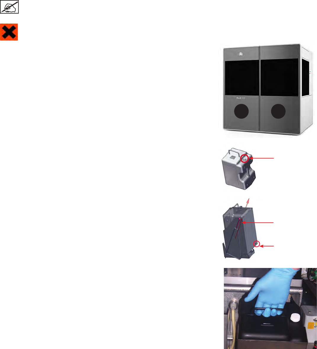
3D Systems, Inc.
MATERIAL CONTAINER REMOVAL
When a material container is empty and needs to be relled, or if a partially lled container needs to be replaced with a full container,
perform the following procedure.
It is important to verify the type of material currently in the MDM before proceeding with these steps.
IRRITANT! Wear protective clothing, disposable nitrile gloves, and goggles, while performing the following steps:
1. Open the front door of the system for the correct print zone.
2. Place the vent cap on the vent hole and screw tightly to
prevent the material from dripping on the currently installed
bottle. The vent cap is the cap that was removed when
material was originally placed in the material bin.
Release Lever
3. Pull down on the MDM release lever which is located to the
left of the material bin, away from the MDM at a 45° angle.
Release Lever
Container Release
Button
Container Release Button
4. Push the container release button, located on the lower right
corner of the material bin.
5. Lift the handle to remove the container. Dispose of the
container according to local regulations.
6. Using a disposable paper towel, wipe all material from the
container seal assembly. If you notice any material on the
container seal assemblly use a paper towel with a small
amount of isoporopyl alcohol on it to clean it up.
A B
Vent Cap
42
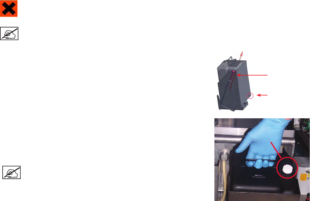
3D Systems, Inc.
Vent Cap
REPLACING MATERIAL CONTAINERS
IRRITANT! Wear protective clothing, disposable nitrile gloves, and goggles, while performing the following steps:
Note: Before adding a new container, make sure that the container slot is empty. If a container is present, refer to the
previous section, Material Container Removal on page 42 before continuing.
To place a material bottle into the MDM, perform the following steps:
1. Open the print chamber doors.
2. Obtain a material bottle ensuring that it is the same material as currently installed
in the MDM.
3. Pull the rell container’s release lever away from the MDM.
Release Lever
Container Release
Button
4. Insert the material bottle into the slot.
5. Look at the status on the user interface. If the status is okay, push the bottle until
you hear a click. Try to lift up on the bottle, if it does not release it is properly
seated..
6. Remove the vent cap and if the bottle is new puncture a small hole on the bottle
using something with a sharp point such as, a screw driver tip or a drill bit tip.
Note: All bottles have a depression in the area to be punctured. Unless
the vent has been previously punctured, and you are very certain of
this, puncture the vent.
7. Close the rell container door rmly until it latches securely.
8. Close the chamber doors, until they latch securely.
43
3D Systems, Inc.
TROUBLESHOOTING
POWER OUTAGES
If you are present when a power outage occurs, or if you discover that the main power is off, complete the following steps:
1. Switch the main power disconnect off (see Master Power Shut-off on page 9) located in the electronic cabinet at the rear of
the machine, so that it does not automatically start when the power is restored; doing so prevents damage from power surges.
ProX 950 CENTER SHUTDOWN
If you do not plan on operating the system on a regular basis and want to shut it down for an extended period of time, power off the
touchscreen and turn off the main power disconnect. See Master Power Shut-off on page 9.
Note: It takes a substantial amount of time for the system to warm up after a full shutdown/power off. See Material
Delivery Module Temperature Control on page 41.
ERROR SYMPTOMS AND OTHER PROBLEMS
The following table lists common errors and troubleshooting solutions.
SYMPTOM CAUSE ACTION
Controller does not operate. Breaker on DC power supply is
tripped. Reset breaker.
Loose cables or poor connection
exists at the plug.
Check the plugs and cables to ensure that they are tightly
connected and that the electrical outlet is working. Verify that
the unit power switches are ON.
Entire system does not
power up Emergency stop switch, chamber or
control panels are depressed.
Reset switch and press system enable.
Main power plug is not engaged. Plug cord into the wall outlet.
No power is coming from the wall. Reset circuit breaker for the wall outlet.
The circuit breaker is tripped. Reset circuit breaker in the back of the machine.
Printhead does not operate. The Laser(s) are not turned on. Turn the laser power supply key to the ON position. Verify
that the switch on the Laser power supply is ON. Turn on the
Laser(s).
Laser interlock not satised. Read error shown on Laser power supply. Call Customer
Support Hotline on page 44.
3D equipment interlock safety relay
not satised, system will not enable.
Satisfy all safety interlocks or the Laser(s) will not operate.
If interlocks cannot be satised, contact Customer Support
Hotline on page 45.
Elevator, leveler, or
applicator does not move.
Loose cables. Secure all connections.
Door or MDM not engaged. Check that the door/MDM panel interlocks are operating and
system is enabled.
Blown fuse. Contact Customer Support Hotline on page 45.
Bad circuit board or motor driver. Try to move using the Print3D Pro touchscreen application.
Reboot the touchscreen. Contact Customer Support Hotline
on page 45.
14
44

3D Systems, Inc.
CUSTOMER SUPPORT
If you receive an unrecoverable error message, or if you need to contact us for another problem, you may contact our Customer Support
Hotline. Before you call Customer Support with a problem or question, please make sure that you have the following information:
• The serial number of your ProX 950 (located on the rear panel)
• A brief description of the problem, including the exact error message
• When the problem occurred; for example, when you submitted a job, during the beginning or the end of a print, or after power
off recovery
CUSTOMER SUPPORT HOTLINE
Please contact your Customer Support Hotline at one of the following numbers:
• In North America, call 1-800-793-3669
• In Asia and the Pacic Rim, call +852 2923 5077
• In Germany, call +49-6151-357 357
• In the United Kingdom, call +44 1442 282665
• In France, call (+33) 01 60 87 88 77
• In Italy, call +49 (0) 6151 357 357
• In Switzerland, call +41-26-439 95 90
• In Japan, call (+81) 3 5451 1690
15
SERVICE
GENERAL
ProX 950 service procedures must be performed only by a 3D Systems-certied service technician unless this guide explicitly
states otherwise. If your system needs service, contact 3D Systems Technical Support at the following numbers:
• In the United States or Canada, call 800-793-3669
• In Europe, call +49-6151-357357
You can also contact your local 3D Systems representative.
3D Systems’ support portal is located at http://www.3dsystems.com/support
For material safety data sheet, go to http://www.3dsystems.com/support/materials/msds
LASER
UV Radiation
All Laser service procedures may only be performed by 3D Systems certied service technicians. Attempts by non-
certied personnel to perform Laser service procedures can result in serious injury. All ProX 950 users must observe
the guidelines and warnings located in the section Laser Safety on page 9.
The ProX 950 conforms to applicable requirements of 21 CFR Subchapter J at the date of manufacture. It is designated a Class I Laser
Device by the Center for Devices and Radiological Health (CDRH). In normal operation, the Laser beams are completely conned and
the viewing windows in the Process Module block the UV Laser radiation. However, if the Laser cover, doors, or windows, are removed
for any reason, the unit becomes a dangerous Class IV Laser device. Direct or reected Laser power from a Class IV Laser device can
cause eye damage. See Laser Safety on page 9 for more information.
16
45

3D Systems, Inc.
MAINTENANCE
CAUTION: If the equipment is used in a manner not specied by the manufacturer, the protection provided by the
equipment may be impaired.
DUST REMOVAL
Remove dust from the outer surfaces of the ProX 950 by wiping with a clean, dry, lint-free cloth.
CAUTION! Do not remove any outer panels when cleaning the system. Panels must be removed only by a qualied 3D
Systems Customer Support Representative.
PREVENTIVE MAINTENANCE
Your ProX 950 must have preventive maintenance performed by a qualied 3D Systems Customer Support Representative. Contact 3D
Systems after one year of printing time.
The charcoal lter will be replaced every six months during the preventive maintenance performed by a qualied 3D Systems Customer
Support Representative.
17
46

3D Systems, Inc.
LEGAL NOTICES
COPYRIGHT AND CORPORATE IDENTITY
Copyright 3D Systems, Inc. All rights reserved. Subject to change without notice. This document is copyrighted and contains proprietary
information that is the property of 3D Systems, Inc. The licensed user, in the name of whom this document is registered (the “Licensed
User”) does not have the right to copy, reproduce, or translate this document in any way or to any media without the prior written
consent of 3D Systems, Inc. No copies of the document may be sold or given to any person or other entity.
IMPROVEMENTS
3D Systems may (but shall not be obligated to) make improvements to this document from time to time. However, the Licensed User
acknowledges that at any time after the expiration of the date of issuance, 3D Systems may institute a periodic charge or fee payable
by the Licensed User in return for ongoing receipt of improvements. It is the responsibility of the Licensed User to provide 3D Systems
with current information as to its name and address. The Licensed User also undertakes to notify 3D Systems promptly in the event
that it considers any of the data contained in this document to be incomplete or erroneous in any respect, in connection with Licensed
User’s particular or general use.
FCC NOTICE
This equipment has been tested and found to comply with the limits for a class A digital device, pursuant to Part 15 of the FCC
Rules. These limits are designed to provide reasonable protection against harmful interference when the equipment is operated in a
commercial environment. This equipment generates, uses, and can radiate radio frequency energy and, if not installed and used in
accordance with the instruction manual, may cause harmful interference to radio communications. Operation of this equipment in a
residential area is likely to cause harmful interference in which case, the user will be required to correct the interference at his own
expense.
Changes or modications not expressly approved by 3D Systems could void your authority to operate equipment.
Ce dispositif est conforme aÌ la norme CNR-210 d’Industrie Canada applicable aux appareils radio exempts de licence. Son
fonctionnement est sujet aux deux conditions suivantes: (1) le dispositif ne doit pas produire de brouillage preìjudiciable, et (2) ce
dispositif doit accepter tout brouillage rec?u, y compris un brouillage susceptible de provoquer un fonctionnement indeìsirable.
This Class A digital apparatus complies with Canadian ICES-003.
Cet appareil numérique de la classe A est conforme à la norme NMB-003 du Canada.
RADIO FREQUENCY TRANSMISSION
This product generates 13.56 MHz using an Inductive Loop System as a Radio Frequency Identication device (RFID). This RFID
device complies with the requirements specied in FCC Part 15, Industry Canada RSS-210, European Council Directive 99/5/EC, and
all applicable local laws and regulations.
Operation of this device is subject to the following two conditions: (1) this device may not cause harmful interference, and (2) this device
must accept any interference received, including interference that may cause undesired operation.
The device referenced in this guide contains transmitter, FCC ID: 2ADGF-SKTKM1 IC: 12666A-SKTKM1
The device referenced in this guide contains transmitter, FCC ID: 2ADGF-CLDRIDQK IC: 12666A-CLDRIDQK
Access to the transmitter for service technicians is available through common enclosure access methods including use of common
tools and removal of covers.
NOTE: Changes or modications to this equipment not specically approved by 3D Systems may void the user’s
authority to operate this equipment.
18
47

3D Systems, Inc.
EC DECLARATION OF CONFORMITY
LA DÉCLARATION DE CE DE CONFORMITÉ
We, 3D SYSTEMS, INC. herewith declare that the following described machine in our delivered
version complies with the basic safety and health requirements of the EC Directive 2006/42/EC of the
European Parliament and of the Council of 17 May 2006, based on its design and type, as brought
into circulation by us. In case of alteration of the machine, not agreed upon by us, the declaration will
lose its validity.
Nous, 3D SYSTEMES, INC. ci-joint déclarer que le suivre a décrit la machine dans notre version
livrée se conforme à la sûreté fondamentaux et aux conditions de santé des Directive de CET
2006/42/EC du Parlement européen et du Conseil 17 Mai 2006, a basé au dessous sa conception
et son type, comme amené dans la circulation par nous. En cas du changement de la machine, pas
consenti sur par nous, la déclaration perdra sa validité.
Description of the machine:
La description de la machine:
Machine type:
Usiner le type:
Serial Number:
Numéro de série
Applicable EC Directives:
Les Directives applicables
de CE:
Applicable Harmonized EC
Standards:
Les Normes de CET Harmonisé
applicables:
Manufactured in USA for
Fabriqué dans l’USA pour
Company Name:
Nom de compagnie: :
Brian Alexander
Director, Manufacturing
Le directeur, les fabriquant
Date
STEROLITHOGRAPHY APPARATUS
ProX 950 Production Modeling Systems
DIRECTIVE 2006/42/EC OF THE EUROPEAN PARLIAMENT AND
OF THE COUNCILof 17 May 2006 on machinery, and amending
Directive 95/16/EC (recast), EMC Directive (2004/108EC)
EN/IEC61010-1, 3rd Edition; E, EN/IEC60825-
1:2007, EN 61000-6-2:2005; EN6000-6-4:2007
Corporate Headquarters
3D Systems Corporation
333 Three D Systems Circle
Rock Hill, SC 29730
USA
3D Systems Europe Ltd.
Mark House, Mark Road
Hemel Hempstead
Hert HP2 7UA
United Kingdom
Year of Manufacture:
Année de Fabrication
48

3D Systems, Inc.
GLOSSARY
Beam prole
A pattern of circles or numbers representing the spatial distribution of Laser beam power. This power distribution automatically
calculates drawing speeds to determine whether the Laser should be adjusted or replaced, and to indicate whether the optics should be
adjusted, replaced, or cleaned.
Beam proler
A UV-sensitive detector over which the Laser beam is moved to generate beam proles. Two beam prolers are mounted in the print
chamber.
Border
A vector that denes the perimeter of a layer. Hatch and ll vectors are drawn between borders.
Print le(s)
The data le(s) produced by the Print3D Pro software and used by the controller to print parts.
Print3D Pro
Touchscreen interface application through which the user operates the system.
CDRH
Center for Devices and Radiological Health.
CFR
Code of Federal Regulations.
Control computer
The computer located inside the electrical cabinet of the system which interfaces directly with the hardware used to print parts.
Cure
The process of turning liquid material into a solid by exposure to UV light.
Cure depth
The thickness or depth of a line of cured material. The cure depth of any line is determined by the Laser beam power and distribution,
Laser draw speed, and material characteristics.
Curl
A characteristic type of part deformation.
Draining
Enabling material to drip from the nished part into the MDM when the elevator is at its top position.
Drawing speed
The speed at which the Laser traces over the surface of the material to form solid plastic lines and surfaces. The drawing speed varies
depending on the depth of solidication requested, Laser beam power and distribution, and material characteristics.
Dynamic mirrors
Motor driven scanning mirrors with encoder feedback that direct the Laser beam to any point on the surface of the material.
Elevator
The hardware components that raise and lower the platform and part in the vertical (Z) axis. Also called Z-stage.
Exposure
The total light energy absorbed by a point on the material surface. Exposure increases with higher Laser power and decreases with
higher drawing speed.
Fill vectors (skin ll)
Overlapping parallel vectors that comprise the horizontal surfaces (skins) of stereolithographic parts.
19
49
3D Systems, Inc.
Green part
A stereolithographic part prior to UV post-curing, but after Laser curing in the material delivery module.
Hatch
A vector that is drawn between layer borders and comprises the interior of the part.
Hatch spacing
A parameter that species the perpendicular distance between adjacent hatch vectors.
Laser
Light Amplication by Stimulated Emission of Radiation. The device that generates the light energy required to polymerize photocurable
material.
Layer
Thin horizontal section of Laser solidied material.
Layer thickness
The depth of a solidied layer of material, as requested by the user.
Leveling
The process whereby the surface of the material is adjusted to the correct distance from the dynamic mirrors.
Line
A line of cured plastic generated by overlapping bullets. See also vector.
Linewidth
The horizontal width of a Laser cured material line.
Monomer
A low molecular weight chemical species, which is a printing block of polymers.
MSDS/SDS
Material Safety Data Sheet/Safety Data Sheet. Federal government mandated information about the chemical makeup of any chemical
substance, such as material. Usually includes identication of toxic substances and safe handling guidelines.
NIOSH
National Institute for Occupational Safety and Health.
Photoinitiator
A chemical in photopolymers that reacts with photons and catalyzes the polymerization process.
Photopolymer
A chemical substance composed of photoinitiators and monomers that polymerizes when exposed to light energy.
Photopolymerization
The process whereby light energy converts monomers into a polymer.
Platform
The perforated base on which parts are printed by the ProX 950.
Platform locators
Features that secure and position the edges of the platform.
Platform supports
L-shaped brackets that support the platform and attach it to the elevator.
Polymer
A material built up from a series of smaller units (monomers). The molecular size of the polymer helps to determine the mechanical
properties of the plastic material.
Polymerization
The process of linking small molecules (monomers) into larger molecules (polymers) comprised of many monomer units.
50
3D Systems, Inc.
Post-Curing Apparatus (PCA) and ProCure equipment
A device which generates ultraviolet energy used to cure green stereolithographic parts.
Post-process
The process of cleaning, curing, and nishing stereolithographic parts.
Printhead
The assembly which contains the IPM and scanning mirrors.
Print Applicator
The assembly of a ProX 950 that either applies material to, or removes excess material from the part, as the applicator moves across
the material surface.
Print chamber
The chamber in which the MDM, elevator, and beam prolers are located.
Material Delivery Module (MDM)
The metal container inside the process chamber in the ProX 950 that holds the material from which the part is formed. On older SLA
Centers, the MDM is referred to as the vat.
Safety shutter
A mechanical device that blocks the Laser beam when an interlock switch is activated or when closed via the computer user interface.
Scan speed
See Draw speed.
Sensitization
An allergic response to a chemical stimulus, such as material, generally resulting from repeated skin contact.
Skin (skin ll)
See Fill vectors.
SLA Center
See Stereolithography apparatus.
Stereolithography apparatus
The equipment used to produce stereolithographic parts.
Slice resolution
A slice parameter that species the number of slice units assigned to each CAD unit of measure.
Stereolithography
A three-dimensional imaging process that forms plastic objects by solidifying successive layers of photocurable material.
Stereolithography le (STL)
The tessellated (triangulated) CAD input le.
Supports
Structures designed on the CAD system or by Print3D Pro to support a part above the elevator platform, provide a rigid foundation on
which the object may be printed, and attach and support layer sections.
Sweep
A pass of the print applicator from the front of the material delivery module to the rear or from rear to front. The act of removing excess
material from the upper surface of the part or adding a layer of fresh material during the application process.
Tessellate
To represent CAD surfaces in polygonal format.
Trapped Volume
During printing, a volume of material within the part that cannot ow out to the surrounding liquid.
51
3D Systems, Inc.
Triangle normal
A line perpendicular to a triangle starting at its center and pointing away from the mass of the part. Triangle normals are used to
differentiate between inside and outside surfaces of a solid.
Ultraviolet (UV)
Electromagnetic radiation having a wavelength shorter than visible light, (i.e., below 390 nanometers).
Vat
On older SLA Centers, the metal container inside the process chamber that holds the material from which the object is formed. On the
ProX 950, this container is called the MDM.
Vector
A directed line segment represented by starting and ending coordinates as dened in a stereolithography slice or print le.
Zephyr™ Print Applicator System
A print applicator system that uses an internal vacuum cavity to deposit material onto the part, decreasing the volume of material which
becomes trapped.
Z-Stage
See Elevator.
52
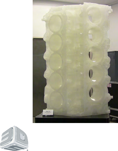
3D Systems, Inc.
333 Three D Systems Circle | Rock Hill, SC | 29730
www.3dsystems.com
©2015 3D Systems, Inc. All rights reserved.
P/n 285391-00 Rev. C