Manual

G2wifiIII
User’s Guide
Version: 1.0
Date: September 18, 2013
3JTech Co., Ltd.
2F, No. 342, Fu-Shing N. Rd.
Taipei, Taiwan
Tel: +886-2-2500 6916
e-mail: info@3jtech.com.tw

http://www.3jtech.com.tw
http://www.pnpipcameras.com
G2wifiIII User’s Guide
Copyright of 3JTech Co., Ltd. (also doing business as A3J Engineering Inc.)
2
Revision History
Version Date Changes
1.0 09/18/2013 First Release of G2wifiIII User’s Manual

http://www.3jtech.com.tw
http://www.pnpipcameras.com
G2wifiIII User’s Guide
Copyright of 3JTech Co., Ltd. (also doing business as A3J Engineering Inc.)
3
Table of Contents
Revision History .......................................................................................................................... 2
TABLE OF CONTENTS .............................................................................................................. 3
CHAPTER 1. PRODUCT OVERVIEW .......................................................................................... 6
1.1 INTRODUCTION ..................................................................................................................... 6
1.2 FEATURES ............................................................................................................................ 7
1.3 PACKAGE CONTENTS ............................................................................................................ 8
CHAPTER 2. PHYSICAL DESCRIPTION .................................................................................... 9
2.1 PANELS ................................................................................................................................ 9
2.1.1 Front Panel .................................................................................................................. 9
2.1.2 Rear Panel ................................................................................................................. 10
2.2 ILLUSTRATION .................................................................................................................... 11
2.2.1 Front Panel Information ............................................................................................ 12
Power Supply Connector ................................................................................................ 12
WAN Port ........................................................................................................................ 12
LAN Network Connectors .............................................................................................. 12
RESET Button ................................................................................................................. 12
2.2.2 Rear Panel Information ............................................................................................. 12
LEDs ................................................................................................................................ 12
2.2.3 LED Description on the Rear Panel ......................................................................... 13
CHAPTER 3. WEB-BASED MANAGEMENT ............................................................................ 14
3.1. INTERNET SETTINGS ........................................................................................................... 16
3.1.1 WAN .......................................................................................................................... 16
3.1.1.1 Static(Fixed IP) WAN Mode ............................................................................... 17
3.1.1.2 DHCP(Auto Config) WAN Mode ......................................................................... 17
3.1.1.3 PPPoE (ADSL) WAN Mode ................................................................................ 18
3.1.2 LAN ............................................................................................................................ 19
3.1.3 DHCP Client .............................................................................................................. 21
3.1.4 Advanced Routing Settings ....................................................................................... 22
3.2 WIRELESS SETTINGS ........................................................................................................... 23
3.2.1 Basic Wireless Settings ............................................................................................ 23
3.2.2 Wireless Security/Encryption Settings .................................................................... 28
3.2.2.1 Disable Mode ...................................................................................................... 28
3.2.2.2 WEPAUTO(WEP) Mode ...................................................................................... 29
3.2.2.3 WPA-PSK / WPA2-PSK Mode .......................................................................... 31

http://www.3jtech.com.tw
http://www.pnpipcameras.com
G2wifiIII User’s Guide
Copyright of 3JTech Co., Ltd. (also doing business as A3J Engineering Inc.)
4
3.2.3 Station List ................................................................................................................ 33
3.2.4 Wireless Statistics .................................................................................................... 34
3.3 FIREWALL SETTINGS .......................................................................................................... 35
3.3.1 MAC/IP/Port Filtering Settings ................................................................................ 35
3.3.2 Port Forwarding Settings ......................................................................................... 37
3.3.2.1 Create a Port Forwarding .................................................................................. 37
3.3.3 DMZ Settings ............................................................................................................. 40
3.3.4 System Security Settings ......................................................................................... 41
3.4 MANAGEMENT .................................................................................................................... 43
3.4.1 System Management ................................................................................................. 43
3.4.2 TR-069 ...................................................................................................................... 45
3.4.3 Firmware Upgrade .................................................................................................... 46
3.4.4 Configuration Management ....................................................................................... 47
3.4.5 Status ......................................................................................................................... 48
3.4.6 Statistic ...................................................................................................................... 49

http://www.3jtech.com.tw
http://www.pnpipcameras.com
G2wifiIII User’s Guide
Copyright of 3JTech Co., Ltd. (also doing business as A3J Engineering Inc.)
5
FCC STATEMENT
1. This device complies with Part 15 of the FCC Rules. Operation is subject to the following two conditions:
(1) This device may not cause harmful interference.
(2) This device must accept any interference received, including interference that may cause undesired operation.
2. Changes or modifications not expressly approved by the party responsible for compliance could void the user's authority
to operate the equipment.
NOTE: This equipment has been tested and found to comply with the limits for a Class B digital device, pursuant to Part
15 of the FCC Rules. These limits are designed to provide reasonable protection against harmful interference in a
residential installation.
This equipment generates uses and can radiate radio frequency energy and, if not installed and
used in accordance with the instructions, may cause harmful interference to radio communications. However, there is no
guarantee that interference will not occur in a particular installation. If this equipment does cause harmful interference to
radio or television reception, which can be determined by turning the equipment off and on, the user is encouraged to try to
correct the interference by one or more of the following measures:
Reorient or relocate the receiving antenna.
Increase the separation between the equipment and receiver.
Connect the equipment into an outlet on a circuit different from that to which the receiver is connected.
Consult the dealer or an experienced radio/TV technician for help.
FCC Radiation Exposure Statement
This equipment complies with FCC radiation exposure limits set forth for an uncontrolled environment. This equipment
should be installed and operated with minimum distance 20cm between the radiator & your body
http://www.3jtech.com.tw
http://www.pnpipcameras.com
G2wifiIII User’s Guide
Copyright of 3JTech Co., Ltd. (also doing business as A3J Engineering Inc.)
6
1. Product Overview
1.1 Introduction
G2wifiIII, a WiFi Router with a WAN port, is the perfect option to connect a small group of PCs to a
high-speed broadband Internet connection or to an Ethernet backbone. Configurable as a DHCP
server, G2wifiIII acts as the only externally recognized Internet device on your local area network
(LAN). The G2wifiIII also serves as an Internet firewall to protect your network from being accessed
by outside users.

http://www.3jtech.com.tw
http://www.pnpipcameras.com
G2wifiIII User’s Guide
Copyright of 3JTech Co., Ltd. (also doing business as A3J Engineering Inc.)
7
1.2 Features
y Router
Mode
‐
3 WAN Modes (It includes Static(Fixed IP), DHCP(Auto Config) and PPPoE (ADSL))
‐
DHCP
Sever
‐
NAPT
(Network Address and Port
Translation)
‐
NAT
(Network Address
Translation)
y Internet
Access
‐
TCP/IP,
UDP, ICMP, ARP, PPP, NAT, DHCP (Server), Static IP
assignment
y Security
Features
‐
Password
protected configuration
access
‐
User
authentication (PAP/CHAP) for PPP
connection
y Wireless
Features
‐
Support
802.11b/g, 802.11n draft 3.0 Wireless Access
Point
‐
Support
128-Bit and 64-Bit WEP encryption, WPA-PSK, WPA2-PSK
y
Security
‐
Support
packet inspection and
filtering
‐
Intrusion
detection and
protection
‐
Password
protected system
management
y Ethernet
Interface
‐
Compliant
with IEEE 802.3 and 802.3u 10/100
Mbps
y HTTP Web-Based
Management
‐
Firmware
upgrade by
UI
‐
WAN
and LAN side connection
statistics
‐
Password
protected
access
‐
Wireless
LAN
y
Support TR-069 management function

http://www.3jtech.com.tw
http://www.pnpipcameras.com
G2wifiIII User’s Guide
Copyright of 3JTech Co., Ltd. (also doing business as A3J Engineering Inc.)
8
1.3 Package Contents
─ 1 x G2wifiIII
─ 1 x RJ45 Ethernet Cable
─ 1 x Power Adapter
─ 1 x CD with this User’s Manual
─ Quick Setup Guide
http://www.3jtech.com.tw
http://www.pnpipcameras.com
G2wifiIII User’s Guide
Copyright of 3JTech Co., Ltd. (also doing business as A3J Engineering Inc.)
9
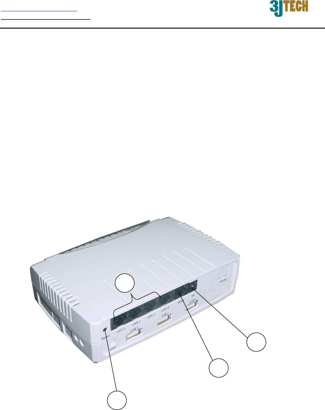
2. Physical Description
The following information contains the physical description of the G2wifiIII. This includes the
functions and the locations of each connector and indicator. This information provides useful
reference when installing the product. Please familiarize yourself with the G2wifiIII.
2.1 Panels
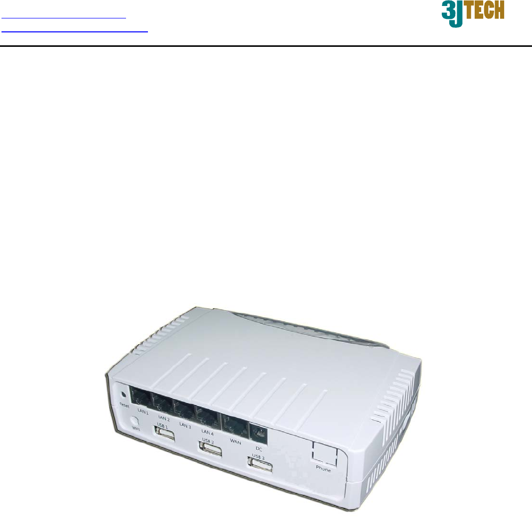
2.1.1 Front Panel
For more related description, please refer to the Section 2.2 and Section 2.2.1.
4
2
3
1

http://www.3jtech.com.tw
http://www.pnpipcameras.com
G2wifiIII User’s Guide
Copyright of 3JTech Co., Ltd. (also doing business as A3J Engineering Inc.)
10
2.1.2 Rear Panel
For more detailed description, please refer to the Section 2.2 and Section 2.2.2.
5

http://www.3jtech.com.tw
http://www.pnpipcameras.com
G2wifiIII User’s Guide
Copyright of 3JTech Co., Ltd. (also doing business as A3J Engineering Inc.)
11
2.2 Illustration
No. in
Figures
Name on
G2wifiIII Description Remark
1 Power Supply
Connector
To connect with the G2wifiIII
and the power adapter
Refer to Section 2.2.1 for front
panel information
2 WAN Port For the access of Internet Refer to Section 2.2.1 for front
panel information
3 LAN Network
Connectors
To connect to the device and
Ethernet port via RJ45 cable
Refer to Section 2.2.1 for front
panel information
4 Reset Button To reset the G2wifiIII to its
factory defaults
Refer to Section 2.2.1 for front
panel information
5 LEDs
To display the status of
G2wifiIII
Refer to Section 2.2.2 for rear
panel information and Section
2.2.3 for LED description on the
rear panel

http://www.3jtech.com.tw
http://www.pnpipcameras.com
G2wifiIII User’s Guide
Copyright of 3JTech Co., Ltd. (also doing business as A3J Engineering Inc.)
12
2.2.1 Front Panel Information
Power Supply Connector
Plug the power adapter. The specifications of G2wifiIII’s power adapter are as follows:
Input: 100 ~ 240V AC, 50/60Hz
Output: 12V DC / 1.5A
WAN Port
Offer the access of Internet.
LAN Network Connectors
G2wifiIII is designed for 10/100Mbps Ethernet networks. G2wifiIII connects to the network via
category 5 cable.
RESET Button
Support the hardware reset function. Press this button 2 seconds around, and the settings of the
device will return to the factory defaults.
Note: Please do not power off the router while resetting it to the factory default.
2.2.2 Rear Panel Information
LEDs
Include the LEDs of POWER, WLAN (Wireless LAN), LAN Link, and WAN Link.

http://www.3jtech.com.tw
http://www.pnpipcameras.com
G2wifiIII User’s Guide
Copyright of 3JTech Co., Ltd. (also doing business as A3J Engineering Inc.)
13
2.2.3 LED Description on the Rear Panel
LED Color Status
POWER( ) Yellow Lit when +12V DC power is on and working.
WLAN(Wireless LAN ) Yellow
Lit when the WiFi function is enabled.
Flash when the data is transmitting.
Off when the WiFi function is disabled.
LAN Link( ) Yellow
Lit when the cable connection with device exists.
Flash when the data is transmitting.
Off when no cable connection exists.
WAN Link( ) Yellow
Lit when the cable connection with device exists.
Flash when the data is transmitting.
Off when no cable connection exists.
http://www.3jtech.com.tw
http://www.pnpipcameras.com
G2wifiIII User’s Guide
Copyright of 3JTech Co., Ltd. (also doing business as A3J Engineering Inc.)
14
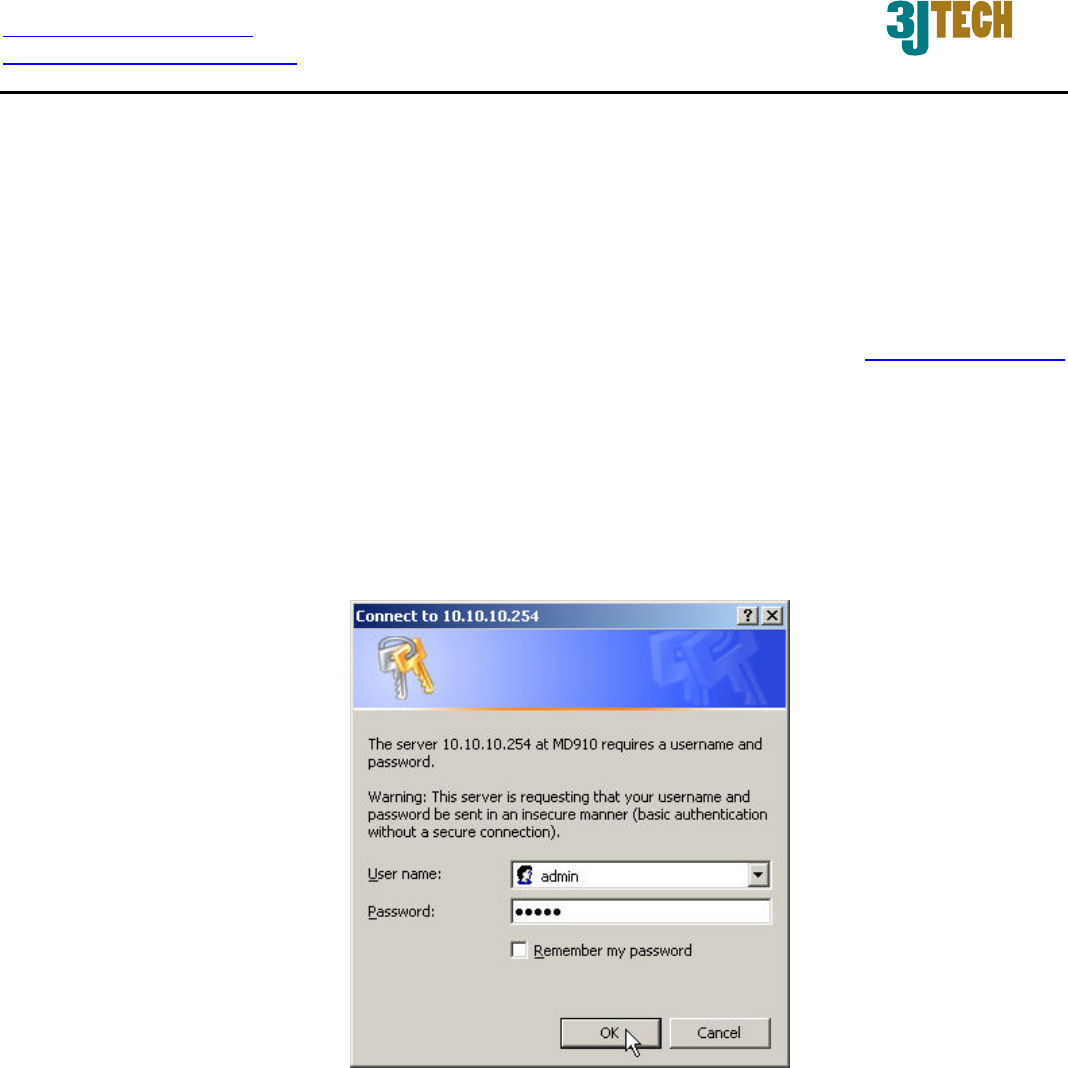
3. Web-Based Management
This chapter instructs you how to configure and manage the G2wifiIII through the web user interface
it supports. With this facility, you can easily access and monitor through the LAN port of the G2wifiIII.
After the G2wifiIII has been connected to your PC via RJ45 network cable, type http://10.10.10.254
in IE browser, it will show the following screen and ask you to input the user name and password in
order to login and access authentication. The default user name and the password are both “admin”.
For the first time to use, please enter this default user name and the password, then click the OK
button. The root setup page for G2wifiIII will be displayed once the login process is successful. The
user will be able to fully access and configure the system.
http://www.3jtech.com.tw
http://www.pnpipcameras.com
G2wifiIII User’s Guide
Copyright of 3JTech Co., Ltd. (also doing business as A3J Engineering Inc.)
15
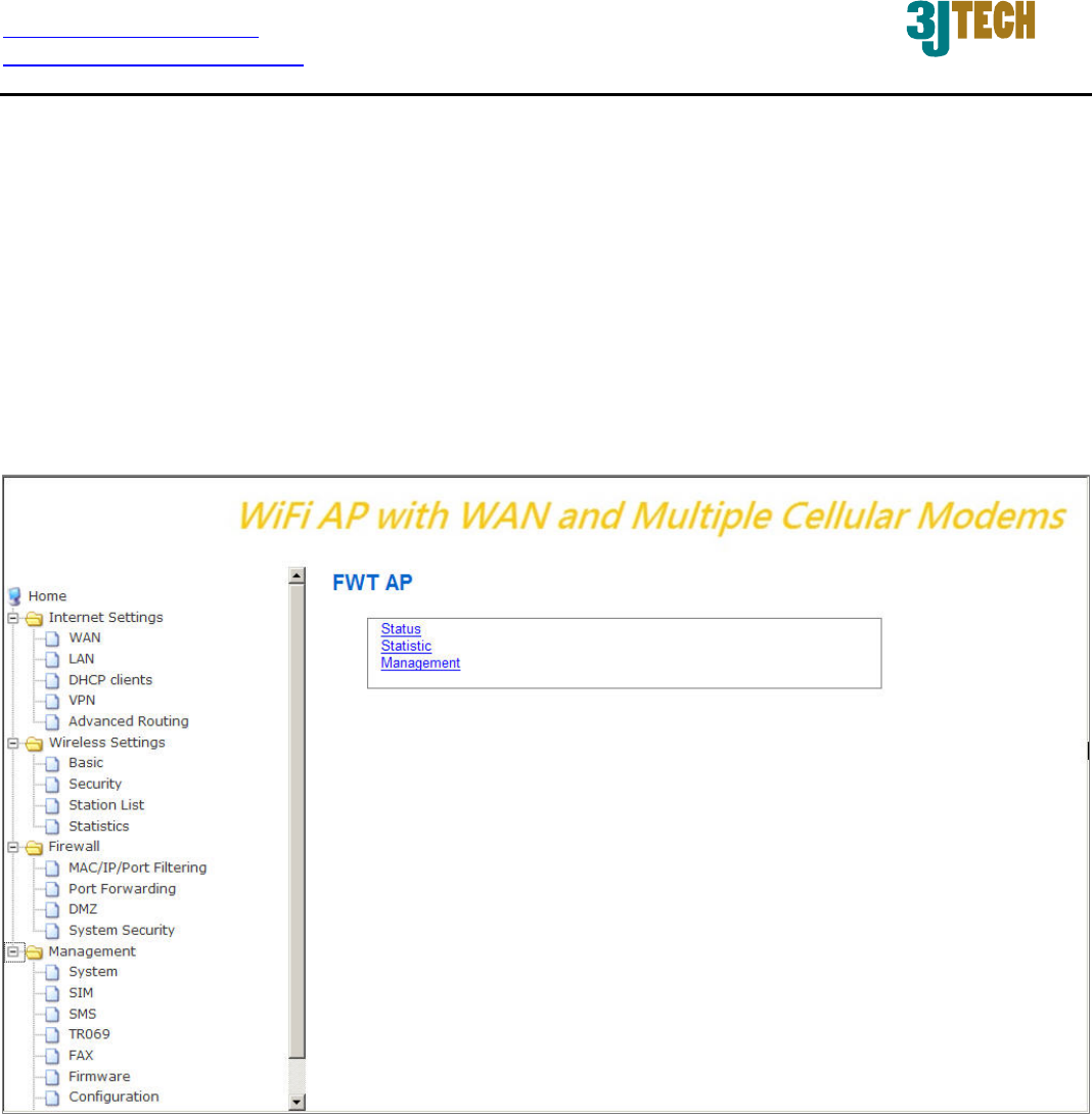
In the G2wifiIII, it supports a simple user management function to configure the system. As the figure
below shows, for example, left section is the whole function tree with web user interface while each
of main functions, including INTERNET SETTINGS, WIRELESS SETTINGS, FIREWALL, and
MANAGEMENT is selected.
By means of the hyperlink of Status, Statistic or Management in this root setup page, you can directly
jump to the related pages if you would like to realize the basic information of the system.
http://www.3jtech.com.tw
http://www.pnpipcameras.com
G2wifiIII User’s Guide
Copyright of 3JTech Co., Ltd. (also doing business as A3J Engineering Inc.)
16
3.1. Internet Settings
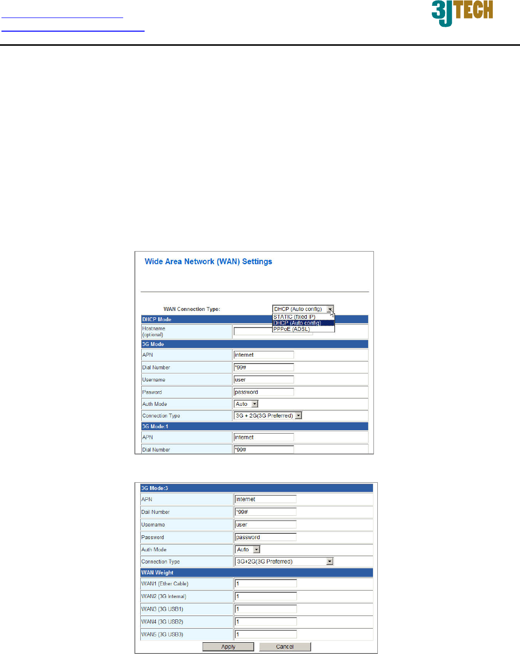
3.1.1 WAN
The WAN (Wide Area Network) section is where you configure your Internet connection type. There
are three WAN connection modes to choose from: Static (Fixed IP), DHCP(Auto Config) and
PPPoE(ADSL). If you are unsure of your connection method, please contact your Internet Service
Provider before configuring the required parameters. Note: If using the PPPoE option, you will need
to ensure that any PPPoE client software on your computers is removed or disabled.
:
:
http://www.3jtech.com.tw
http://www.pnpipcameras.com
G2wifiIII User’s Guide
Copyright of 3JTech Co., Ltd. (also doing business as A3J Engineering Inc.)
17
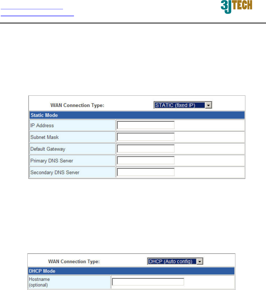
3.1.1.1 Static(Fixed IP) WAN Mode
Used when your ISP provides you a set IP address that does not change. The IP information is
manually entered in your IP configuration settings. You must enter the IP address, Subnet Mask,
Default Gateway, Primary DNS Server, and Secondary DNS Server. Your ISP provides you with
all of this information.
3.1.1.2 DHCP(Auto Config) WAN Mode
A method of connection where the ISP assigns your IP address when your router requests one from
the ISP's server. Some ISP's require you to make some settings on your side before your router can
connect to the Internet.
Hostname: Some ISP's may check your computer's hostname. The hostname identifies your
system to the ISP's server. This way they know your computer is eligible to receive an IP
address. In other words, they know that you are paying for their service.
http://www.3jtech.com.tw
http://www.pnpipcameras.com
G2wifiIII User’s Guide
Copyright of 3JTech Co., Ltd. (also doing business as A3J Engineering Inc.)
18
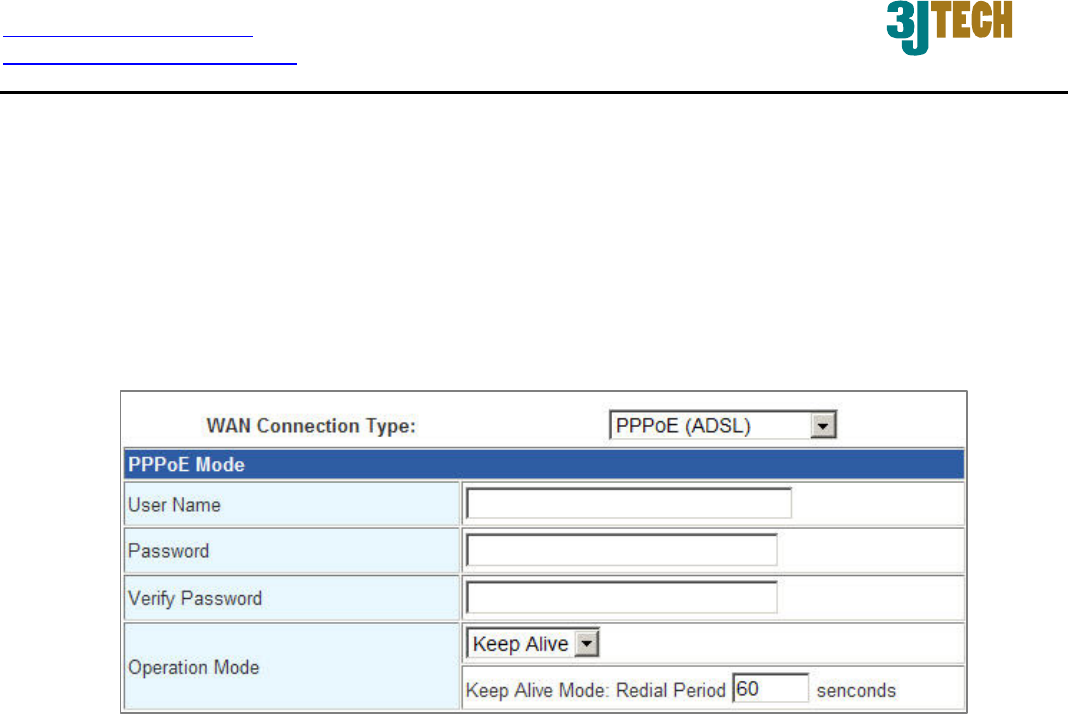
3.1.1.3 PPPoE (ADSL) WAN Mode
Select this option if your ISP requires you to use a PPPoE (Point to Point Protocol over Ethernet)
connection. DSL providers typically use this option. This method of connection requires you
to enter a User Name and Password (provided by your Internet Service Provider) to gain
access to the Internet.
Operation Mode: Typically, connections are not always on. The router allows you to set the
reconnection mode. The setting is:
Keep Alive: A connection to the Internet is always maintained. When this option is
selected, please enter a value in the field of Redial Period which is the time
interval the machine will be redialed before the PPPoE connection is disconnected.
http://www.3jtech.com.tw
http://www.pnpipcameras.com
G2wifiIII User’s Guide
Copyright of 3JTech Co., Ltd. (also doing business as A3J Engineering Inc.)
19
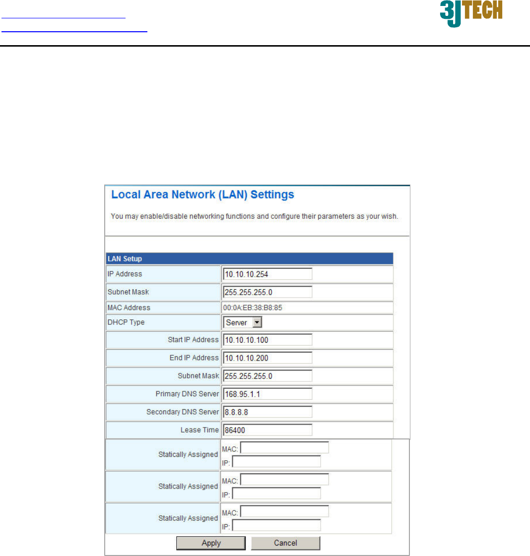
3.1.2 LAN
These are the settings of the LAN (Local Area Network) interface for the AP. The AP's local
network (LAN) settings are configured based on the IP Address and Subnet Mask assigned in this
section. The IP address is also used to access this web-based management interface. It is
recommended that you use the default settings if you do not have an existing network.
IP Address: The IP address of your router’s LAN port. Default: 10.10.10.254.
Subnet Mask: Subnet Mask of your LAN (default: 255.255.255.0). All devices on the network
must have the same subnet mask to communicate on the network.
DHCP Type: DHCP stands for Dynamic Host Configuration Protocol. The DHCP section is
where you configure the built-in DHCP Server to assign IP addresses to the computers and
other devices on your local area network (LAN). When you select Server item from this
pull-down list to enable this function, the following parameters will be displayed. You must enter
the IP address, Subnet Mask, Primary DNS Server and/or Secondary DNS Server.

http://www.3jtech.com.tw
http://www.pnpipcameras.com
G2wifiIII User’s Guide
Copyright of 3JTech Co., Ltd. (also doing business as A3J Engineering Inc.)
20
Start IP Address: Specify the DHCP Client IP address that will start.
End IP Address: Specify the DHCP Client IP address that will end.
Note: The number of the “End IP” must be greater than “Start IP”, and cannot be the same as the
router’s IP address.
DHCP Lease Time: Designate the amount of the time for the device to recycle and give out
the IP addresses to the devices in your network (default: 86400).
Statically Assigned: You can statically assign the client MAC and IP address. Up to three
IPs and MACs can be assigned.
http://www.3jtech.com.tw
http://www.pnpipcameras.com
G2wifiIII User’s Guide
Copyright of 3JTech Co., Ltd. (also doing business as A3J Engineering Inc.)
21
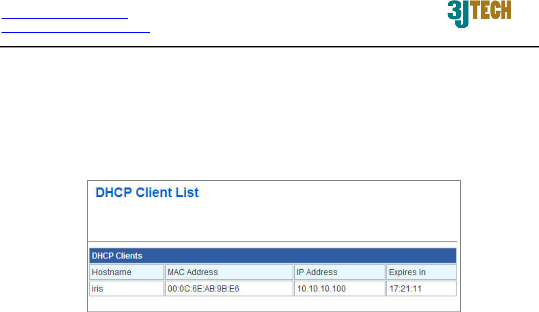
3.1.3 DHCP Client
In this section, you can see clearly which devices are currently leasing IP addresses that you had
defined for the DHCP Server‘s allocation of addresses to computers and devices on your Local Area
Network.
Host Name: A name for each computer or device that is given an IP address by the DHCP
Server. This may help you keep track of which computers are assigned this way.
MAC Address: A MAC address is usually located on a sticker at the bottom of a network
device. The MAC address is comprised of twelve digits. Each pair of hexadecimal digits are
usually separated by dashes or colons such as 00-0D-88-11-22-33 or 00:0D:88:11:22:33.
IP Address: The address which is obtained from the DHCP Server.
Expires in: The remaining time of the IP address’s lease. A specific LAN device no longer
needs the leased IP address when the time ends up, and this device will also free the IP
address it had leased.
http://www.3jtech.com.tw
http://www.pnpipcameras.com
G2wifiIII User’s Guide
Copyright of 3JTech Co., Ltd. (also doing business as A3J Engineering Inc.)
22
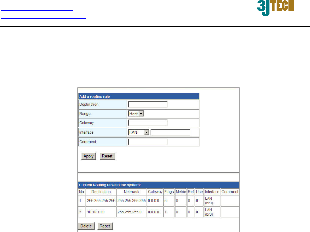
3.1.4 Advanced Routing Settings
In Static Routing Settings, the user can set up a route rule (table) here. Refer to the description of the
following parameters to set up the necessary route rule, and click the Apply button when you
complete.
Destination: The IP address of packets that will take this route.
Range: Includes Host and Net options. When selecting “Net”, there is another “Netmask”
column that needs to be filled out.
Netmask: The bits in the mask specify which bits of the IP address must match.
Gateway: The gateway for the routing.
Interface: Specifies the interface -- LAN or WAN -- that the IP packet must use to transit out of
the router when this route is used. Or you can choose the user-defined way by selecting the
Custom option.
Comment: Memo for the routing rule.
Routing Table: Lists the current route rules you have added before. Click on the Delete button
to delete the selected route rule.
http://www.3jtech.com.tw
http://www.pnpipcameras.com
G2wifiIII User’s Guide
Copyright of 3JTech Co., Ltd. (also doing business as A3J Engineering Inc.)
23
3.2 Wireless Settings
The wireless section is used to configure the wireless settings for your router. Please note that
changes made on this section may also need to be duplicated on your wireless client.
To protect your privacy, use the wireless security mode to configure the wireless security features.
This device supports three wireless security modes including: WEP(WEPAUTO), WPA-PSK, and
WPA2-PSK. WEP is the original wireless encryption standard. WPA provides a higher level of
security. In WPA encryption, it supports TKIP or AES of WPA-PSK/WPA2-PSK.
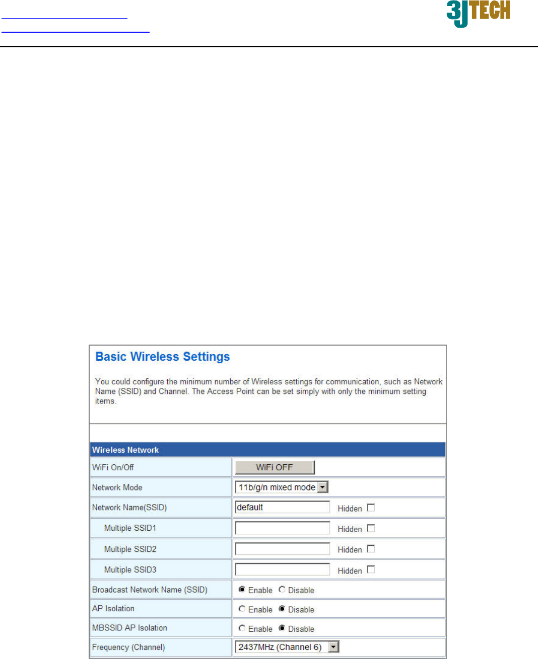
3.2.1 Basic Wireless Settings
Through the basic wireless setting page, the user can control the ON/OFF status of WiFi function,
and set up the 802.11 mode, Network Name (SSID) as well as Channel. Besides, you can do the
further settings related to the HT Physical Mode.
http://www.3jtech.com.tw
http://www.pnpipcameras.com
G2wifiIII User’s Guide
Copyright of 3JTech Co., Ltd. (also doing business as A3J Engineering Inc.)
24
Wireless Network
Settings:
WiFi On/Off: This option turns on and off the wireless connection feature of the router. Simply
click on the WiFi ON / WiFi OFF button. The system will automatically detect the current status
of the router and switch the button accordingly.
Network Mode: There are 5 modes including, 802.11b/g mixed mode, 802.11b only, 802.11g
only, 802.11/b/g/n mixed mode, and 802.11n only(2.4G) can be chosen.
Network Name(SSID): When you are browsing for available wireless networks, this is the
name that will appear in the list (unless you set it to Hidden, see below). This name is also
referred to as the SSID. For security purposes, it is highly recommended to change from the
pre-configured network name. Default is “default”.
Hidden: The option allows you to hide your wireless network. When this option is
unchecked, your wireless network name is broadcast to anyone within the range of your
signal. If you're not using encryption then they could connect to your network. When you
click on this checkbox to enable this function, you must enter the Wireless Network Name
(SSID) on the client manually to connect to the network.
Multiple SSID 1 ~ 3: Up to three SSIDs you can additionally set up for this wireless network.

http://www.3jtech.com.tw
http://www.pnpipcameras.com
G2wifiIII User’s Guide
Copyright of 3JTech Co., Ltd. (also doing business as A3J Engineering Inc.)
25
Broadcast Network Name (SSID): Enable/Disable the SSID broadcast function. This function
is used to control the broadcast status of all SSIDs. If this function is disabled, all SSIDs you
had set up for the router will be hidden. To cancel the hidden status for the specific SSID, you
can uncheck the “Hidden” option in the back of your desired SSID.
AP Isolation: Enable/Disable this function. Create a separate virtual network for your wireless
network. When this feature is enabled, each of your wireless clients will be in its own virtual
network and will not be able to communicate with each other. You may want to utilize this
feature if you have many guests that frequent your wireless network.
MBSSID AP Isolation: Enable/Disable the MBSSID AP Isolation function. The router supports
multiple SSIDs. You can decide whether the clients associated to different SSIDs on the device
can see each other or not. Enable the option to block it. Default is “Disable”.
Frequency (Channel): A wireless network uses specific channels in the 2.4GHz wireless
spectrum to handle communication between clients. Some channels in your area may have
interference from other electronic devices. Choose the clearest channel to help optimize the
performance and coverage of your wireless network. If you select AutoSelect, the router
automatically finds the channel with least interference and uses that channel for wireless
networking.
Rate: Exist only when selecting 802.11b/g mixed mode, 802.11b only, 802.11g only as the
Network Mode for the router. You can set up the desired transmitting rate for these network
modes. Default is Auto.
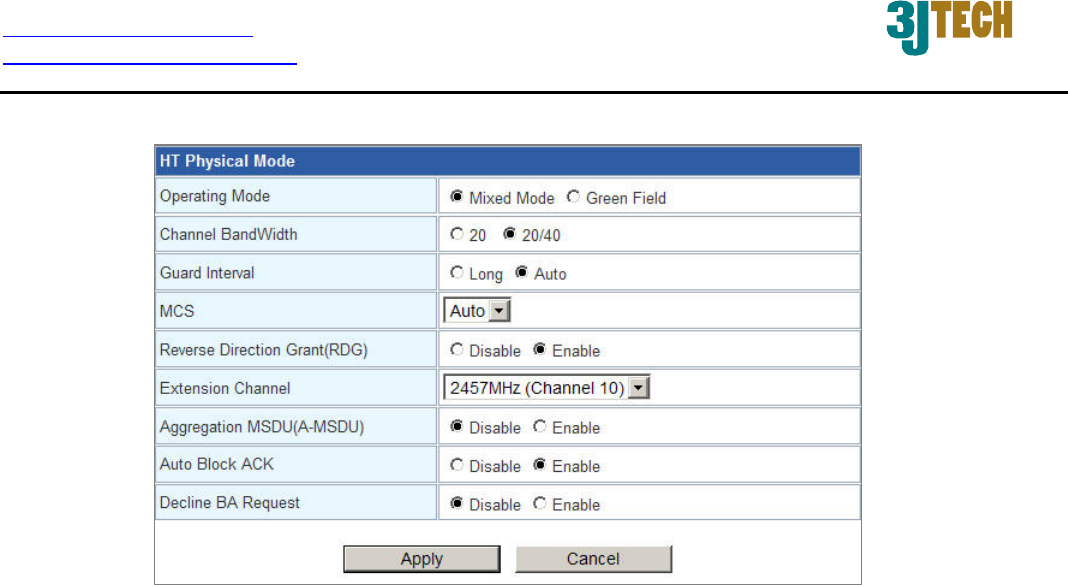
HT Physical Mode Settings:
This mode settings exist only when 802.
11b/g/n mixed mode or
802.11n only(2.4G) is chosen as your router’s Network Mode.
Operating Mode: Select the option to enable the Mixed Mode or the Green Field Mode for
physical layer transceivers. Default: Mixed Mode.
Mixed mode: In this mode the device transmits the packets with preamble compatible
legacy (802.11g), so they can be decoded by legacy devices. The device receives and
decodes both Mixed Mode packets and legacy packets.
Green Field mode: The device transmits HT packets without legacy compatible part. But
the device receives and decodes both Green Field and legacy packets.
http://www.3jtech.com.tw
http://www.pnpipcameras.com
G2wifiIII User’s Guide
Copyright of 3JTech Co., Ltd. (also doing business as A3J Engineering Inc.)
26
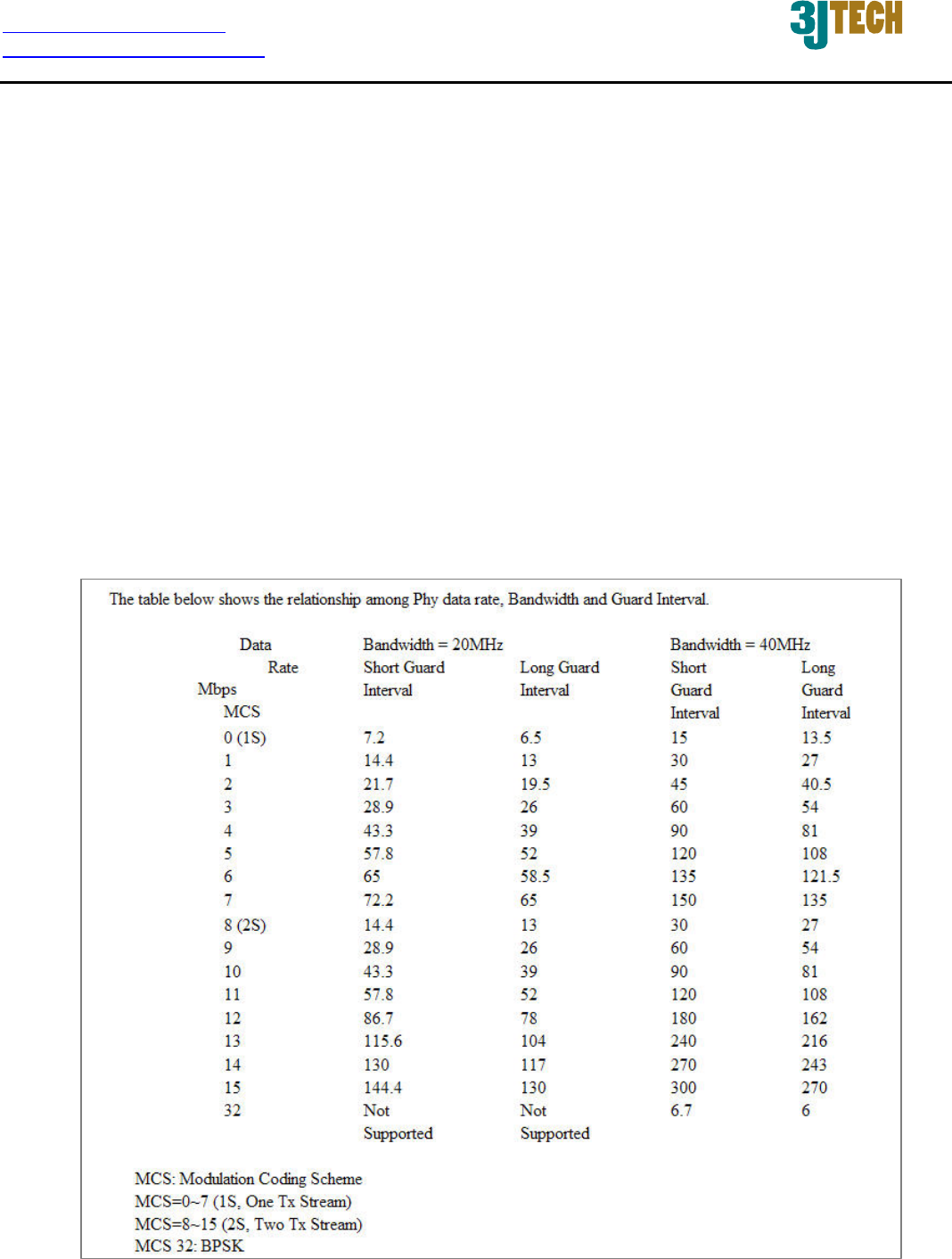
Channel BandWidth: This option only works when selecting Network mode in 11b/g/n mixed
mode and 11n mode. Select the option to choose 20 MHz or 20/40MHz. This option affects the
Phy data rate of radio. Please refer to the table below, which shows the relationship among Phy
data rate, Bandwidth and Guard Interval.
Guard Interval: The 11n device inserts the Guard Interval into the signal. You can choose the
interval between ”Long” and “Auto”. This option affects the Phy data rate of radio. For more
details, please refer to the table below.
MCS: It means “Modulation Coding Scheme”. The available options are “Auto, 0, 1, …15, and
32”. It changes the modulation of this device and effect the maximum Phy data rate. We
recommend “Auto” setting. For more details, please refer to the table below.

http://www.3jtech.com.tw
http://www.pnpipcameras.com
G2wifiIII User’s Guide
Copyright of 3JTech Co., Ltd. (also doing business as A3J Engineering Inc.)
27
Reverse Direction Grant(RDG): This is the 11n performance parameter. Enable it if needed.
Extension Channel: Exist only when selecting “20/40” as the Channel BandWidth for the
router. For example, if channel 6 is selected, it means you can select channel 2 or channel 10
as the extension channel. Choose the unused channel as the extension channel.
Aggregation MSDU(A-MSDU): The multiple HT packets can be transmitted with single ACK
reply packet. Enable it to apply this function and reduce the network congestion.
Auto Block ACK: It is another aggregation technique which prevents sending ACK in the
communication to increase the throughput. If this option is enabled, the device will activate this
function when transmitting massive data.
Decline BA Request: Enable this option to decline the Block ACK request addressed by the
other devices.
http://www.3jtech.com.tw
http://www.pnpipcameras.com
G2wifiIII User’s Guide
Copyright of 3JTech Co., Ltd. (also doing business as A3J Engineering Inc.)
28
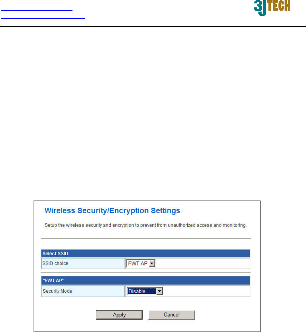
3.2.2 Wireless Security/Encryption Settings
In this section, you can configure the wireless security and encryption to prevent from unauthorized
access and monitoring. Please choose a SSID you had created for this router in the Wireless
Settings Æ Basic setting page from the SSID Choice pull-down list.
There are 4 encryption modes, including Disable, WEPAUTO(WEP), WPA-PSK and WPA2-PSK
offered for your selection. Please also pull down the Security Mode list and select the desired mode
for your router’s wireless security. For more details about the setup in these different modes, please
refer to the following sections.
3.2.2.1 Disable Mode
In this mode, wireless clients can directly connect to the router without inputting any key.
http://www.3jtech.com.tw
http://www.pnpipcameras.com
G2wifiIII User’s Guide
Copyright of 3JTech Co., Ltd. (also doing business as A3J Engineering Inc.)
29
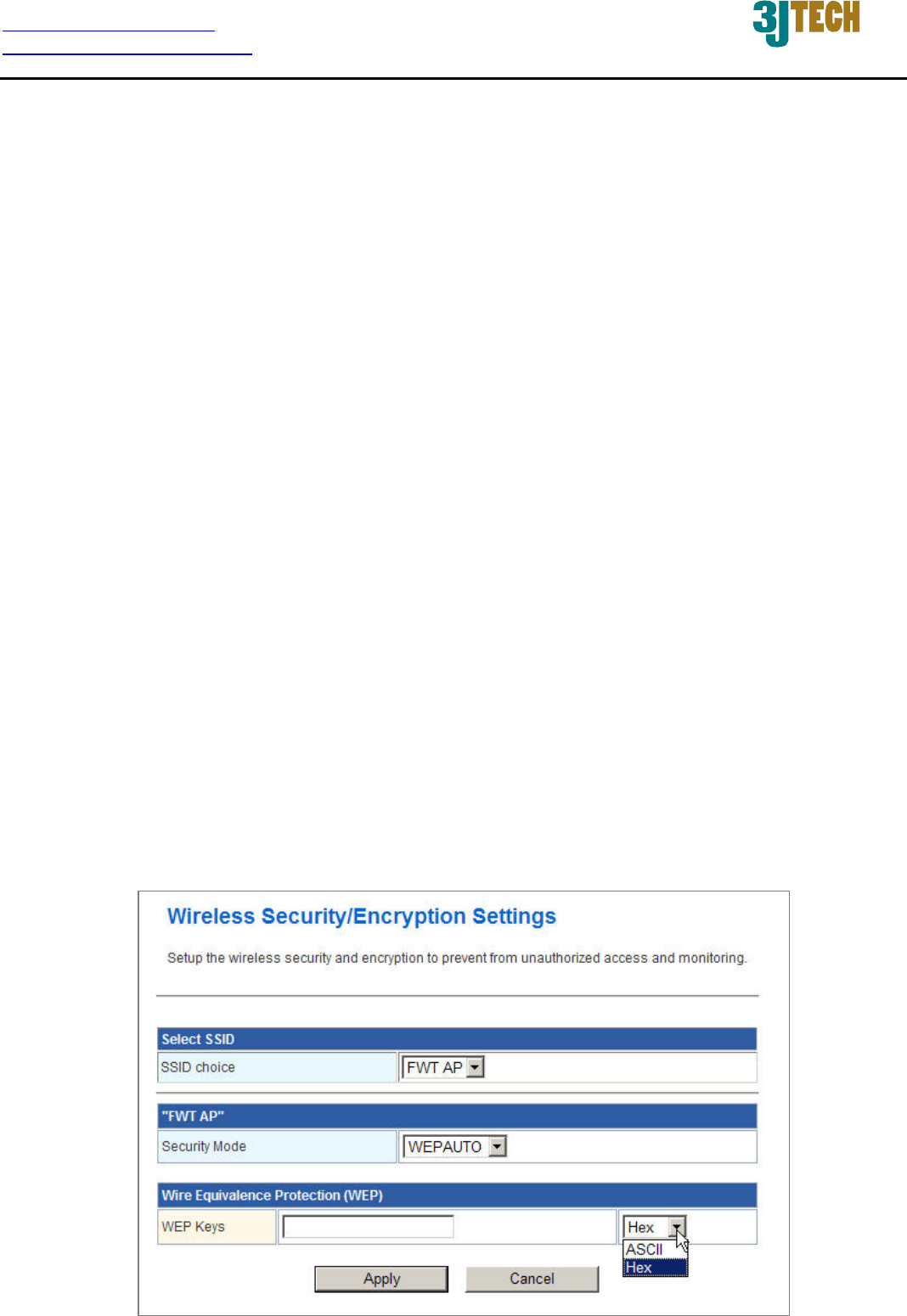
3.2.2.2 WEPAUTO(WEP) Mode
WEP is a method of encrypting data for wireless communication intended to provide the same level
of privacy as a wired network. WEP is not as secure as WPA encryption. To gain access to a WEP
network, you must know the key. The key is a string of characters that you create. When using WEP,
you must determine the level of encryption. The type of encryption determines the key length. 128-bit
encryption requires a longer key than 64-bit encryption. Keys are defined by entering in a string in
HEX (hexadecimal - using characters 0-9, A-F(a-f)) or ASCII (American Standard Code for
Information Interchange - alphanumeric characters) format. ASCII format is provided so you can
enter a string that is easier to remember. The ASCII string is converted to HEX for use over the
network.
Example,
64-bit hexadecimal keys are exactly 10 characters in length. (12345678FA is a valid string
of 10 characters for 64-bit encryption.)
128-bit hexadecimal keys are exactly 26 characters in length.
(456FBCDF123400122225271730 is a valid string of 26 characters for 128-bit encryption.)
64-bit ASCII keys are up to 5 characters in length (DMODE is a valid string of 5 characters
for 64-bit encryption.)
128-bit ASCII keys are up to 13 characters in length (2002HALOSWIN1 is a valid string of
13 characters for 128-bit encryption.)

http://www.3jtech.com.tw
http://www.pnpipcameras.com
G2wifiIII User’s Guide
Copyright of 3JTech Co., Ltd. (also doing business as A3J Engineering Inc.)
30
WEP Keys: Select “ASCII” or “Hex” from the pull-down list to set up the key value. ASCII
(American Standard Code for Information Interchange) is a code for representing char as
numbers from 0-127. Hexadecimal digits consist of the numbers 0-9 and the letters A-F (a-f).

http://www.3jtech.com.tw
http://www.pnpipcameras.com
G2wifiIII User’s Guide
Copyright of 3JTech Co., Ltd. (also doing business as A3J Engineering Inc.)
31
3.2.2.3 WPA-PSK / WPA2-PSK Mode
WPA (Wi-Fi Protected Access) is the older standard; select this option if the clients that will be used
with the router only support the older standard. WPA2 is the newer implementation of the stronger
IEEE 802.11i security standard.
PSK(Pre-Shared Key) is the key which is entered as a pass-phrase of up to 63 alphanumeric
characters in ASCII (American Standard Code for Information Interchange) format or 64 digits in
HEX format at both ends of the wireless connection. When inputting ASCII strings, it cannot be
shorter than eight characters, although for proper security it needs to be of ample length and should
not be a commonly known phrase. This phrase is used to generate session keys that are unique for
each wireless client.
WPA Algorithms: Mark the option to enable modes of TKIP or AES.
Pass Phrase: This mode requires only an access point and client station that supports
WPA-PSK. The WPA-PSK settings include Key Format, Length and Value. They must be as
same as each wireless client in your wireless network. When Key format is Passphrase, the
key value should have 8-63 ASCII characters or 64 digits in HEX format.

http://www.3jtech.com.tw
http://www.pnpipcameras.com
G2wifiIII User’s Guide
Copyright of 3JTech Co., Ltd. (also doing business as A3J Engineering Inc.)
32
Key Renewal Interval: Enter a value to set up the WPA key renewal interval. The device
regenerates the key in every interval seconds that you have setup without disconnection. The
WPA Algorithm will regroup the key for a period. The default value is 3600 seconds, and you
can adjust the time interval (Valid Range: 0 ~ 4194303).
http://www.3jtech.com.tw
http://www.pnpipcameras.com
G2wifiIII User’s Guide
Copyright of 3JTech Co., Ltd. (also doing business as A3J Engineering Inc.)
33
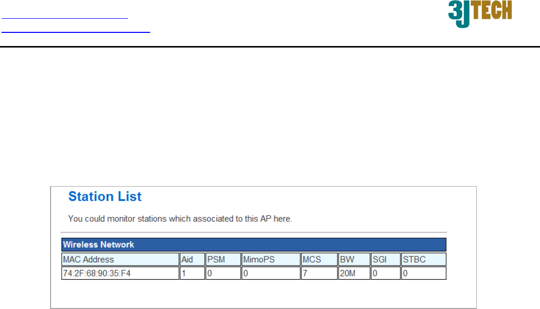
3.2.3 Station List
From the list of Station, you can see which devices are currently connecting to your G2wifiIII in the
wireless way through the MAC address. You also can have a clear realization of status, including Aid,
PSM, MimoPS, MCS, BW(Bandwidth), SGI and STBC for each Wifi connection.
http://www.3jtech.com.tw
http://www.pnpipcameras.com
G2wifiIII User’s Guide
Copyright of 3JTech Co., Ltd. (also doing business as A3J Engineering Inc.)
34
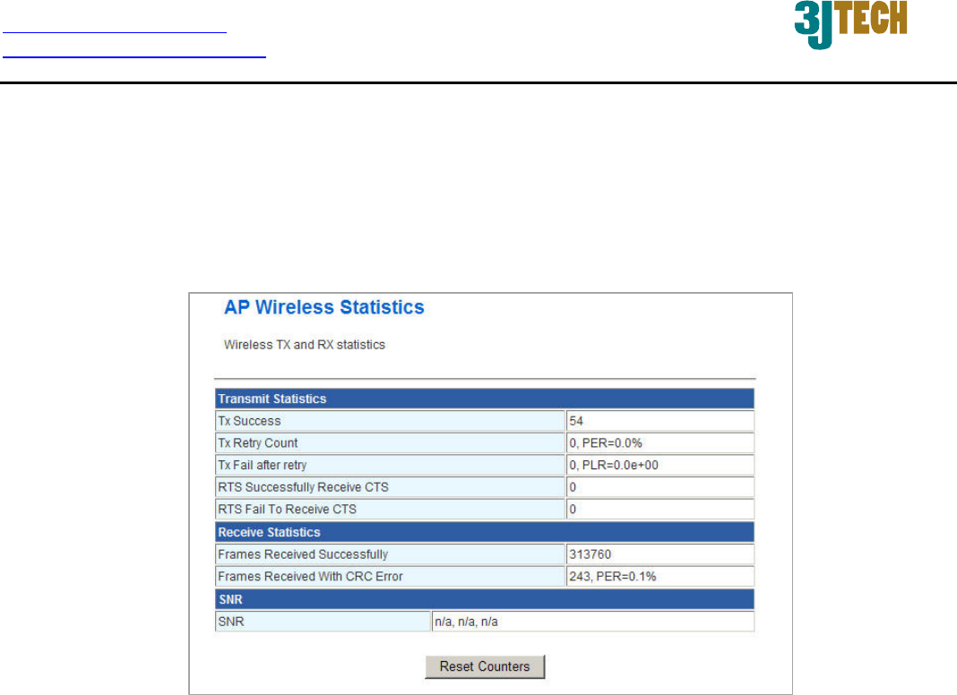
3.2.4 Wireless Statistics
The G2wifiIII offers the counter function to collect all wireless traffic counting information about the
transmitting/ receiving packets of this router. The system will automatically update these wireless
data per 3 seconds. To restart the counting, please click on the Reset Counters button.
Tx Success: Display the transmitted number of the successful packets.
Tx Retry Count: Display the transmitted number of the retry packets.
Tx Fail after retry: Display the transmitted number of the unsuccessful packets after retry.
RTS Successfully Receive CTS: Display the transmitted number of RTS(Request To Send)
packets which receive CTS(Clear To Send) packets successfully.
RTS Fail To Receive CTS: Display the transmitted number of RTS(Request To Send) packets
which receive CTS(Clear To Send) packets unsuccessfully.
Frames Received Successfully: Display the received number of the successful frames.
Frames Received With CRC Error: Display the received number of frames with CRC error
packets.
SNR: Signal-to-Noise ratio (SNR). It stands that how fast wireless data of the router can travel
and how far a wireless signal of the router can reach.
http://www.3jtech.com.tw
http://www.pnpipcameras.com
G2wifiIII User’s Guide
Copyright of 3JTech Co., Ltd. (also doing business as A3J Engineering Inc.)
35
3.3 FireWall Settings
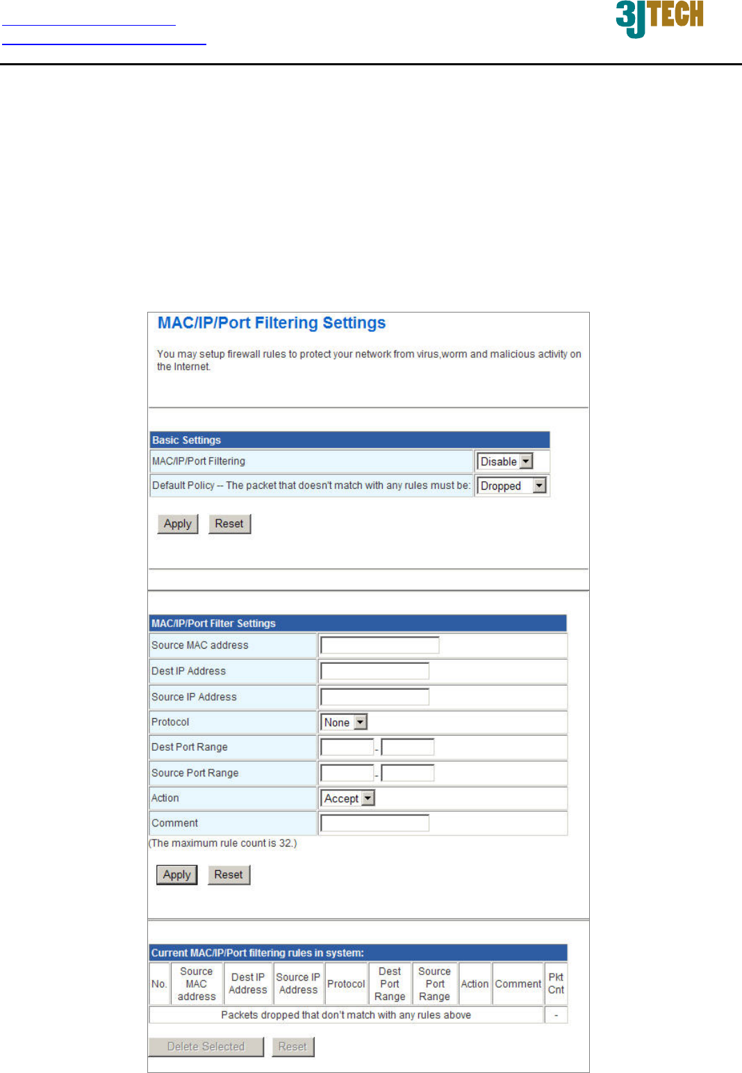
3.3.1 MAC/IP/Port Filtering Settings
The router could filter the outgoing packets for security or management consideration. You can set
up the filter against the IP addresses to block specific internal users from accessing the Internet. The
firewall could not only obstruct outside intruders from intruding your system, but also restricting the
LAN users. Port filter restricts certain type of data packets from your LAN to Internet through the
router.

http://www.3jtech.com.tw
http://www.pnpipcameras.com
G2wifiIII User’s Guide
Copyright of 3JTech Co., Ltd. (also doing business as A3J Engineering Inc.)
36
Basic
Settings:
MAC/IP/Port Filtering: Enable/Disable the function of MAC/IP/Port Filtering.
Default Policy - The packet that doesn’t match with any rules must be: Dropped/Accepted.
For example, if you select “Dropped”, all packets that do not match the rule you set up in the
following
MAC/IP/Port FilteringSettings
would be dropped.
MAC/IP/Port Filtering Settings:
Source MAC address: Fill out the MAC address that you wish to filter.
Dest IP Address: Fill in the destination IP address that you wish to filter.
Source IP Address: Fill in the source IP address that you wish to filter.
Protocol: Select the protocol type of TCP, UDP or ICMP.
Dest Port Range: Fill in the destination port range that you wish to filter.
Source Port Range: Fill in the source port range that you wish to filter.
Action: You can either choose “Accept” or “Drop” to permit or prevent the action.
Comment: Input any text to describe this mapping, up to 16 alphanumerical characters.
IP/Port Filter Rule List: Lists the IP / Port Filter Settings you have added before. Click on the
Delete Selected button to delete the selected list.
http://www.3jtech.com.tw
http://www.pnpipcameras.com
G2wifiIII User’s Guide
Copyright of 3JTech Co., Ltd. (also doing business as A3J Engineering Inc.)
37
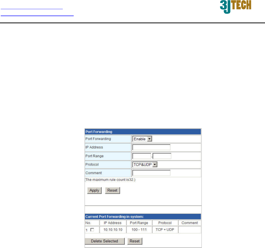
3.3.2 Port Forwarding Settings
This function offers the way of Port Forwarding / Virtual Server in order to help redirect requests from
computers on the LAN to a server set up on the LAN. You can set up an Internet service on the
computer on local network, without exposing it on Internet directly. You can also build many sets of
port redirection, to provide many different Internet services on different local computers via a single
Internet IP address.
3.3.2.1 Create a Port Forwarding
In this section, you can add a new port forwarding to the port forwarding table below or delete an
existing entry from this table.
Port Forwarding: Enable/Disable the function of Port Forwarding.
IP Address: Fill in the IP address of your LAN Server.
Port Range: Fill in the port range that you wish to filter.
Protocol: Select the protocol type, including TCP, UDP or TCP&UDP used by the service.
Comment: Input any text to describe this mapping. Up to 16 alphanumeric characters can be
filled in.
Port Forwarding Mapping List: After completing the above settings, please click on the
Apply button. The entry of Port Forwarding you had added will be listed on this table if it is
created successfully. Clicking on the Delete Selected button will remove the existing entry you
select from this table.

http://www.3jtech.com.tw
http://www.pnpipcameras.com
G2wifiIII User’s Guide
Copyright of 3JTech Co., Ltd. (also doing business as A3J Engineering Inc.)
38
3.3.2.2 Create a Virtual Server
In this section, you can add a new virtual server to the virtual server table below or delete an existing
entry from this table.
The Virtual Server option gives Internet users access to services on your LAN. This feature is
useful for hosting online services such as FTP, Web, or game servers. For each Virtual Server, you
define a public port on your router for redirection to an internal LAN IP Address and LAN port. For
Example,
You are hosting a Web Server on a PC that has LAN IP Address of 10.10.10.50 and your
ISP is blocking Port 80.
1. Enter the IP Address of the machine on your LAN (for example: 10.10.10.50)
2. Enter the Public Port as [8888]
3. Enter the Private Port as [80]
4. Select the Protocol - TCP
5. Click the Apply button to add the settings to the Virtual Server Table
6. Repeat these steps for each Virtual Server Rule you wish to add. With this Virtual
Server entry, all Internet traffic on Port 8888 will be redirected to your internal web
server on port 80 at IP Address 10.10.10.50.

http://www.3jtech.com.tw
http://www.pnpipcameras.com
G2wifiIII User’s Guide
Copyright of 3JTech Co., Ltd. (also doing business as A3J Engineering Inc.)
39
Virtual Server: Enable/Disable the function of Virtual Server.
IP Address: The IP address of the system on your internal network that will provide the virtual
service, for example, 10.10.10.50.
Public Port: The port that will be accessed from the Internet.
Private Port: The port that will be used on your internal network.
Protocol: Select the protocol type, including TCP, UDP or TCP&UDP used by the service.
Comment: Input any text to describe this mapping. Up to 16 alphanumerical characters can be
filled in.
Virtual Server Mapping List: After completing the above settings, please click on the Apply
button. The entry of Virtual Server you had added will be listed on this table if it is created
successfully. Clicking on the Delete Selected button will remove the existing entry you select
from this table.
http://www.3jtech.com.tw
http://www.pnpipcameras.com
G2wifiIII User’s Guide
Copyright of 3JTech Co., Ltd. (also doing business as A3J Engineering Inc.)
40
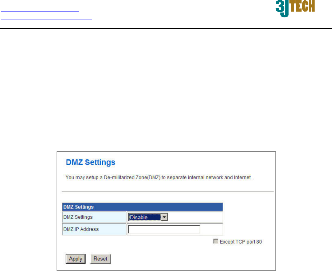
3.3.3 DMZ Settings
The DMZ (Demilitarized Zone) is used to enable protocols, which needs to open ports on the router.
The router will forward all unspecified incoming traffic to the host specified in this setting page. To
configure it, mark to enable virtual DMZ and then enter the Host IP (private IP address) and click the
Apply button to enact the setting.
Note: Putting a computer in the DMZ may expose that computer to a variety of security risks. Use of
this option is only recommended as a last resort.
DMZ Settings: Enable/Disable the function of DMZ.
DMZ IP Address: Specify the IP address of the computer on the LAN that you want to have
unrestricted Internet communication. If this computer obtains its address automatically using
DHCP, then you may want to make a static reservation in the field of Statically Assigned on
the Internet Settings Æ LAN setting page so that the IP address of the DMZ machine does not
change.
Except TCP port 80: If you click on the checkbox in front of Except TCP port 80 function, it
means that TCP port 80 cannot be used for DMZ; otherwise, you can use this port for DMZ.
http://www.3jtech.com.tw
http://www.pnpipcameras.com
G2wifiIII User’s Guide
Copyright of 3JTech Co., Ltd. (also doing business as A3J Engineering Inc.)
41
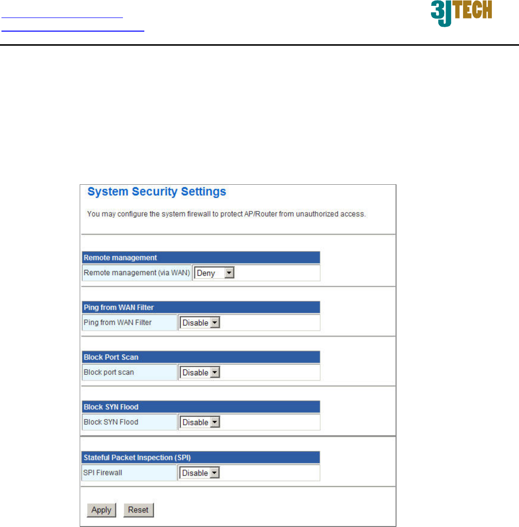
3.3.4 System Security Settings
To improve the safety of the internal network environment, G2wifiIII offers a variety of basic firewall
management functions, including Remote management (via WAN), Ping from WAN Filter, Block port
scan, Block SYN Flood and SPI Firewall. By the configuration the following system security settings,
you can protect the router itself from being attacked, scanned or intruded.
Remote management (via WAN): Allow or Not Allow the user to log in the system with the
WAN IP.
Ping from WAN Filter: Enable/Disable the function of Ping from WAN Filter. If the function is
enabled, the system will reject to response the ICMP(ping) packets coming from the WAN.
Block port scan: Enable/Disable the function of Block port scan. The port scan actions will be
dropped if you enable this function.
Block SYN Flood: Block TCP SYN Flood or not. If this function is enabled, it can prevent the
system from being attacked by a large amount of SYN packets.

http://www.3jtech.com.tw
http://www.pnpipcameras.com
G2wifiIII User’s Guide
Copyright of 3JTech Co., Ltd. (also doing business as A3J Engineering Inc.)
42
SPI Firewall: SPI ("stateful packet inspection" also known as "dynamic packet filtering") helps
to prevent cyberattacks by tracking more state per session. It validates that the traffic passing
through that session conforms to the protocol.
http://www.3jtech.com.tw
http://www.pnpipcameras.com
G2wifiIII User’s Guide
Copyright of 3JTech Co., Ltd. (also doing business as A3J Engineering Inc.)
43
3.4 Management
3.4.1 System Management
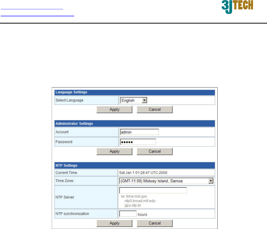
You may configure language, administrator’s account and password, and NTP settings here.
Language Settings: Select the language which you would like. Currently, only English is
included.
Administrator Settings: Modify the account and password to set up and manage the G2wifiIII.
The default settings for administrator are as follows:
Username: admin
Password: admin
NTP Settings: Set up the system time by syncing from the NTP server.
Current Time: Show the system time of the router. Its format: day of week, month, day,
hours : minutes : seconds, year. For instance, Wed, Aug. 29, 12:10:10, 2012.

http://www.3jtech.com.tw
http://www.pnpipcameras.com
G2wifiIII User’s Guide
Copyright of 3JTech Co., Ltd. (also doing business as A3J Engineering Inc.)
44
Time Zone: It is an offset time off GMT. You have to select the time zone first and then
perform time sync via NTP because the router will combine this time zone offset and
updated NTP time to come out the local time, otherwise, you will not able to get the correct
time. The router supports configurable time zone from –11 to +12 step 1 hour. Default
Time zone: -11 Hrs.
NTP Sever: NTP is Network Time Protocol and is used to sync the network time based
Greenwich Mean Time (GMT). If you manually specify an IP address of user-defined NTP
server as well as Time Zone, the router will sync the time immediately after pressing the
Apply button.
NTP Synchronization: Though it synchronizes the time automatically, NTP does not
update the time periodically without user’s processing. You can set up the time interval
(Valid range: 1 ~ 300 hours) to have the assigned NTP server do the synchronization of
time for your router.
http://www.3jtech.com.tw
http://www.pnpipcameras.com
G2wifiIII User’s Guide
Copyright of 3JTech Co., Ltd. (also doing business as A3J Engineering Inc.)
45
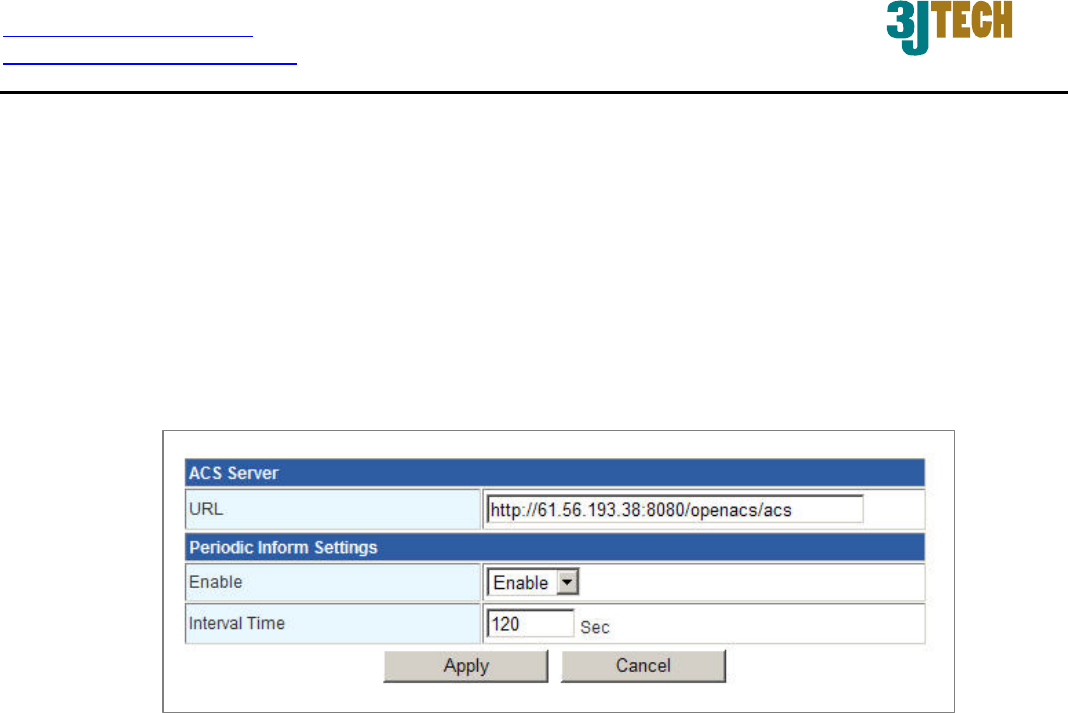
3.4.2 TR-069
Due to the built-in TR-069 function, G2wifiIII will allow the administrator to remotely do the firmware
upgrade, system configuration, management, troubleshooting via the Auto-Configuration Server
(ACS) in the method of HTTP Internet network connection. ACS is a TR-069_based automatic
configuration server, implementing CPE WAN Management Protocol (CWMP). For more details on
the ACS, please refer to our ACS Administrator’s User Manual.
URL of ACS Server: For G2wifiIII’s access of TR-069 service from ACS through the web
browser, please fill in the path in which the ACS is built. For example,
http://61.56.193.38:8080/openacs/acs)
Enable: Activate/Deactivate G2wifiIII’s TR-069 functionality.
Interval Time of Periodic Inform Settings: Enter a value to set up or change the Periodic
Inform Interval of the G2wifiIII. Upon this time interval you had set up, G2wifiIII will
communicate with ACS periodically and automatically. Please note that the value of Periodic
Inform Interval Time must be more than 30 seconds, and the maximum of this Interval Time
can be 4294967295 in seconds.
http://www.3jtech.com.tw
http://www.pnpipcameras.com
G2wifiIII User’s Guide
Copyright of 3JTech Co., Ltd. (also doing business as A3J Engineering Inc.)
46
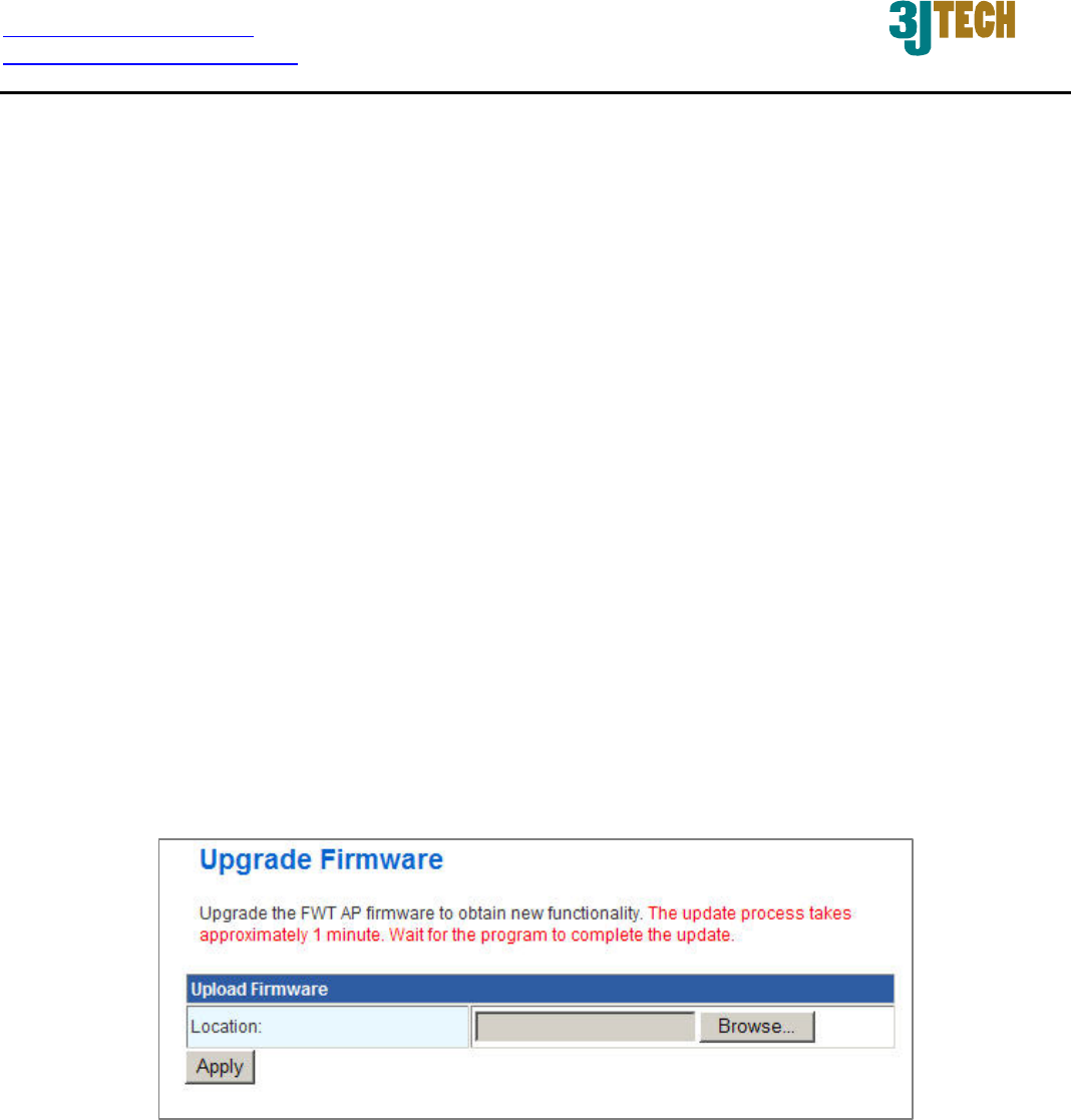
3.4.3 Firmware Upgrade
Software upgrade tool is used to help upgrade the software function in order to fix or improve the
function. User can upgrade the firmware in this page. Please note that power cannot be off in the
process of the software upgrade
. You must do it carefully.
Specify the filename and directory where the file is located via the Browse…button, and click on the
Apply button when it is completed. When the upload is finished, the router will start upgrading
software. A reboot message will be prompted after completing upgrading software. At this time, you
must reboot the router to have the new software worked.
If your upload is unsuccessful, an error message will be shown in the webpage, and it will not
upgrade the software as well.
For G2wifiIII‘s NVRAM value update, you should press the Reset button (more than 2 seconds)
when the device is on and have it restart. And then power off the router and power on for its normal
working.
Location: File path and filename stored the image file you would like to upgrade.
http://www.3jtech.com.tw
http://www.pnpipcameras.com
G2wifiIII User’s Guide
Copyright of 3JTech Co., Ltd. (also doing business as A3J Engineering Inc.)
47
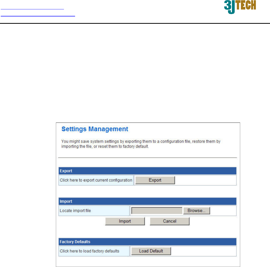
3.4.4 Configuration Management
With this function, user can back up or reload the config files by exporting/ importing settings.
Besides through the press of the RESET button in the front panel to execute the hardware reset
function as we had mentioned in Section 2.2.1 for the router. The software reset function provided
here takes the same effect as the RESET button on the front panel of the router. It will take about
30~60 seconds to complete the system boot.
Export: To export the current settings stored in the flash to a config file, just press the Export
button.
Import: Import the config file into your router. Specify the filename and directory where the file
is located via the Browse…button, and press the Import button when completed.
Factory Defaults: Restoring the unit to the factory default settings will erase all settings,
including any rules that you had created. To have the router’s settings be returned to the factory
default, just press the Load Default button. Please note that the router cannot be powered off
while resetting to the factory default.
http://www.3jtech.com.tw
http://www.pnpipcameras.com
G2wifiIII User’s Guide
Copyright of 3JTech Co., Ltd. (also doing business as A3J Engineering Inc.)
48
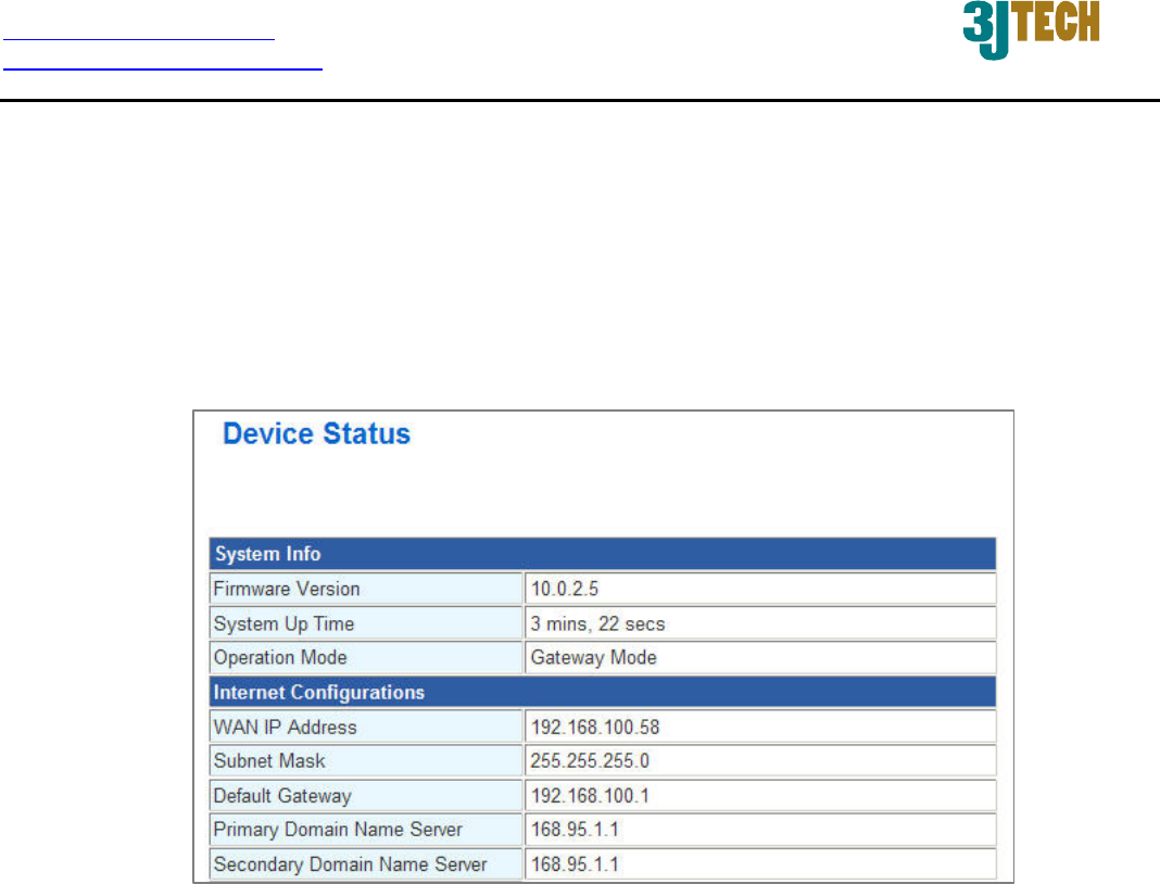
3.4.5 Status
In the Status page, it tells you the basic information of the system. You can check the device status,
including the firmware version, system up time, WAN/Local IP address, MAC address and so on.
They will be refreshed per 3 seconds. With these information, it is helpful while malfunctioning.
http://www.3jtech.com.tw
http://www.pnpipcameras.com
G2wifiIII User’s Guide
Copyright of 3JTech Co., Ltd. (also doing business as A3J Engineering Inc.)
49
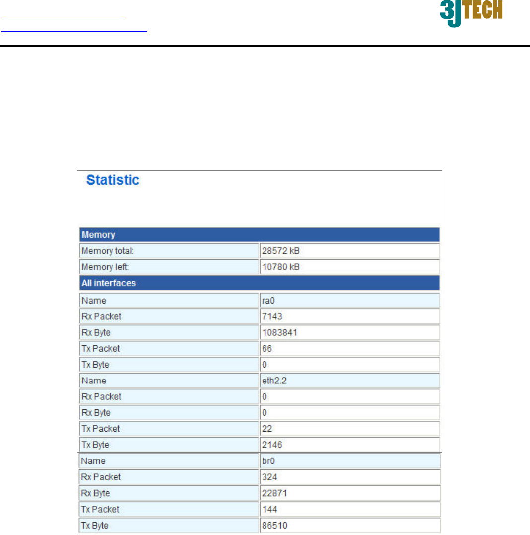
3.4.6 Statistic
G2wifiIII offers the counter function to collect all counting information about the memory status and
all interfaces’ receiving/transmitting packets of this router.