3M Electronic Monitoring IDEU-830-2 Beacon unit User Manual
3M Electronic Monitoring, Inc. Beacon unit Users Manual
Users Manual

One Piece GPS
Offender Tracking
Device (Gen 4) with
Beacon User Manual
2
3M™ One Piece GPS
Offender Tracking
Device (Gen 4) with
Beacon User Manual
February 8, 2015

3
Copyright ©2016 3M. All rights reserved.
No part of this publication may be reproduced, stored in a retrieval system, or
transmitted, in any form or by any means, electronic, mechanical,
photocopying, recording, or otherwise, without the prior written permission of
3M.
The information in this document is subject to change without notice. The
software mentioned in this document is furnished under license and may only
be used or copied in accordance with the terms of such license. Contact
software manufacturers directly for terms of software licenses for any
software mentioned in this document not originating from 3M.
All brand or product names are the trademarks or registered trademarks of
their respective holders.
4
SAFETY INFORMATION
Please read, understand, and follow all safety information contained in these instructions prior
to the use of this 3M Electronic Monitoring device. Retain these instructions for future
reference.
Intended Use:
This 3M Electronic Monitoring device is part of an electronic monitoring system, which
performs data transfer using cellular network to a monitoring platform. This device has not
been tested for and is not intended for use on airplanes, in hazardous environments, in
healthcare facilities, or where cellular phones or other intentional transmitters are restricted.
Safety information for Trained Customer (e.g., officer, agency representative, ministry of
justice) and Offender.
WARNING
• Avoid placing a device next to an implanted electronic device (e.g., don’t carry the device
in a shirt or jacket pocket directly near an implanted device).
• To reduce the risks associated with fire or explosion:
- Do not intentionally open or damage the device.
- Do not enter areas with potentially explosive atmosphere. Potentially explosive areas
are often, but not always, clearly marked.
• To reduce the risks associated with hazardous voltage:
- Do not modify AC/DC power adapter plug.
- Do not force the power plug into an outlet where it does not fit.
- Use only a 3M provided power adapter to recharge or power the device.
- Do not unplug AC/DC adapter by power cord. Handle the adapter by the body only.
- Do not modify, decorate, or attempt to service the device. Return to 3M authorized
personnel or location for repair or service. There are no user serviceable parts.
- Do not attempt to charge the device using an outdoor outlet. Only use the AC/DC
adapter indoors.
- Do not expose power adapter to rain, steam or wet conditions.
Explanation of Signal Word Consequences
WARNING: Indicates a hazardous situation which, if not avoided, could
result in serious injury or death
CAUTION: Indicates a hazardous situation which, if not avoided, could
result in minor or moderate injury and/or property damage.
NOTICE: Indicates a situation which, if not avoided, could result in
property damage.

5
- Do not submerge the device, or hold the device under running water, while it is
charging.
- Do not submerge the device, or hold the device under running water.
CAUTION
• To reduce the risks associated with hot surfaces:
- Do not touch thermal pads on device or charger if charging is interrupted.
Safety information for Trained Customer only.
WARNING
• To reduce the risks associated with fire or explosion:
- Do not attempt to access or replace battery. Battery is not user-replaceable. The
device shall be opened by 3M authorized service only.
- Ensure storage temperature of device is within the range as specified in device manual.
CAUTION
• To reduce the risks associated with sharp points:
- Use caution when handling pin trays.
Safety information for Offender only.
WARNING
• To reduce the risks associated with fire or explosion:
- Risk of explosion if battery is replaced by an incorrect type. Dispose of used batteries
according to the instructions.
- Do not use device outside of the operation temperature range specified in device
manual. Contact the agency representative from which you are monitored to get
operation temperature range.
• To reduce the risks associated with hazardous voltage:
- If the device or power cord becomes damaged, contact the agency representative
from which you are monitored.
NOTICE
• Only authorized personnel can turn off or remove the device.

6
Table of Contents
1 Piece (Gen 4) with Beacon Overview .............................................................................. 7
1 Piece (Gen 4) Features ....................................................................................................... 8
1 Piece (Gen 4) Operating Features .................................................................................... 9
Communication ................................................................................................................. 10
LEDs ..................................................................................................................................... 11
Beacon Overview.................................................................................................................. 15
Beacon Operating Features ............................................................................................... 16
Enrollment ............................................................................................................................. 18
Enroll a Contact................................................................................................................. 19
Contact Information Page ............................................................................................. ..22
Enroll an Offender ............................................................................................................23
Supervision Level ..............................................................................................................24
Map Offender’s Address ................................................................................................. 27
Offender General Information Page ............................................................................. 28
Create Home Curfew Schedule ....................................................................................... 29
Create Exclusion Zone ....................................................................................................... 33
Attaching the 1 Piece (Gen 4) ........................................................................................... 37
Unassigning Hardware ....................................................................................................... 46
Removing the 1 Piece (Gen 4) ........................................................................................... 50
1 Piece (Gen 4) Self Test ..................................................................................................... 52
Appendix ............................................................................................................................... 53
Rule Definitions .................................................................................................................... 53
7
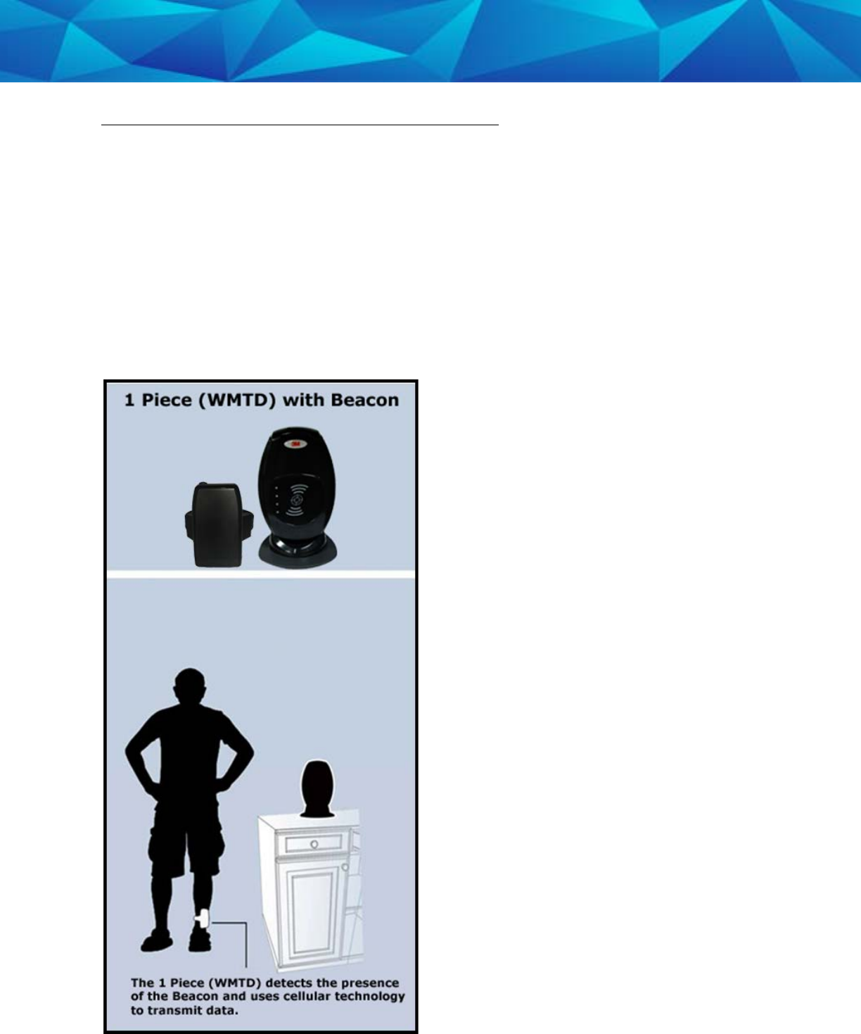
1 Piece (Gen 4) with Beacon Overview
3M Electronic Monitoring’s One-Piece GPS Offender Tracking Device (Gen 4) utilizes
GPS satellites to establish an offender’s location and uses cellular networks to transmit
the location data to 3M Electronic Monitoring. It is a one-piece device that is worn on
an offender’s ankle and is able to function in active and passive mode.
The Beacon is an optional home unit placed in an offender’s home which
communicates with a 1 Piece (Gen 4) through radio frequency. This ensures the
offender is within range of the Beacon during a scheduled home curfew. The home
unit will also act as a beacon to display when the offender is in the “home” or “away”
status.

8
1 Piece (Gen 4) Operating Features
Battery Life: The device should be given a full charge (4.2 volts) to supply a full day of
battery life. It takes approximately 2 to 2 ½ hours to acquire a full charge. The battery
will last approximately 24-30 hours if fully charged. The daily life of the battery is
dependent upon the call-in interval of the device, how often it goes to rest, and how
many violations are created. The battery must be charged each day in order to
continue to track your offender’s locations.
Vibrate feature: The 1 Piece (Gen 4) will vibrate upon violation and when the device
receives an alert from the officer. If the offender causes a violation, the 1 Piece (Gen
4) will vibrate three times consecutively and once every ten minutes until they clear
the violation.
If the officer sends the offender a notification (an alert) to contact them, the 1 Piece
(Gen 4) will vibrate for ten consecutive seconds. As soon as the offender
acknowledges the notification, the vibration will stop. All three LED lights will be
flashing red to indicate that the offender needs to acknowledge the officer’s
notification. If the offender doesn’t acknowledge the notification, then every ten
minutes it will vibrate once until they acknowledge the notification.
Storing GPS Points: The 1 Piece (Gen 4) will store an offender’s location (GPS point)
when in motion (moving) every minute. If the 1 Piece (Gen 4) does not experience any
motion for two consecutive minutes, the 1 Piece (Gen 4) will go to “rest” and collect a
GPS point every hour instead of each minute. As soon as any motion is generated, the
1 Piece (Gen 4) will resume recording points on a minute-to-minute basis. However, if
the offender causes a geographic zone violation, the 1 Piece (Gen 4) will begin to store
a point every 15 seconds.
Call-in intervals: The 1 Piece (Gen 4) will contact 3M Electronic Monitoring every hour
while in active mode and every six hours while in passive mode. While in active mode,
it will also contact 3M Electronic Monitoring immediately upon violation.
Automatic Redial: If the 1 Piece (Gen 4) is unable to communicate with 3M Electronic
Monitoring because of poor cellular coverage, it will continue to try to call and
download its information until it is successful.
Waterproof: The 1 Piece (Gen 4) is waterproof down to 66 feet.

9
1 Piece (Gen 4) Operating Features, Cont.
Rubber strap: The 1 Piece (Gen 4) strap is designed to last nine months to one year.
Magnetized Charger: The 1 Piece (Gen 4) has a magnetized charger to prevent an
accidental disconnect when the battery is being recharged.

10
1 Piece (Gen 4) Operating Features
Communication
The 1 Piece (Gen 4) has a SIM card, which is similar to the data transmitter/receiver
found in most cellular phones. The 1 Piece (Gen 4) uses the SIM card to transmit and
download the GPS points and alarms it has recorded to 3M Electronic Monitoring’s
servers. The call-in intervals are determined by the agency’s contract specifications.
Examples may be hourly, every six hours, or immediately upon alarm.
Active Mode:
• The standard 1 Piece (Gen 4) call-in interval is once every hour while in
compliance.
• The 1 Piece (Gen 4) will call 3M Electronic Monitoring as soon as a violation
occurs.
Passive Mode:
• The standard 1 Piece (Gen 4) call-in interval is once every six hours.
• The 1 Piece (Gen 4) will not call 3M Electronic Monitoring when a violation
occurs. The officer will only be made aware of violations when they view the
GPS maps or the Daily Event Summary Report (DESR) that is emailed to the
officer.
• Violations will also be displayed in Case Management and on the Offender
Monitor.
11
1 Piece (Gen 4) Operating Features
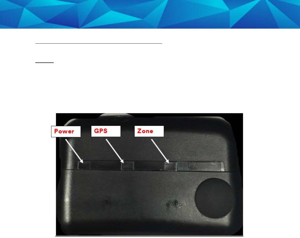
LEDs
There are three LEDs on the top of the 1 Piece (Gen 4), identified as Power, GPS, and
Zone. The three LEDs work separately and provide the offender with information. The
1 Piece (Gen 4) will vibrate to provide an indication that the offender must look at the
LEDs.

12
1 Piece (Gen 4) Operating Details
LEDs
Power
This LED indicates the condition of the 1 Piece (Gen 4) battery.
Prior to Activation:
Before activating the device, the officer should conduct a battery test. To do this,
simply hold down the silver activation button for three seconds and observe the
condition of the Battery LED.
• If the “PWR” LED is green, there is a sufficient charge to activate the 1 Piece
(Gen 4).
• If the “PWR” LED is red, or does not light up at all, the 1 Piece (Gen 4) needs to
be charged.
After Activation:
• If the “PWR” LED is blinking green, there is a sufficient charge.
• If the “PWR” LED is blinking red, the 1 Piece (Gen 4) needs to be charged.
1 Piece (Gen 4) on Charger:
When the 1 Piece (Gen 4) is connected to the charger, the Power LED will be solid (not
flashing) green or red.
• If the LED is red: The 1 Piece (Gen 4) is not fully charged and should not be
disconnected from the charger
• If the LED is green: The 1 Piece (Gen 4) battery has been completely charged
and the charger may be disconnected
• When the 1 Piece (Gen 4) is connected to the charger, it will vibrate once
indicating a good connection. When the battery is fully charged, the 1 Piece
(Gen 4) will vibrate once indicating that it is okay to remove from the charger.

13
1 Piece (Gen 4) Operating Details
LEDs
GPS
Officer:
• During activation, the officer will see this LED flashing green in unison with the
flashing “Zone” LED.
Offender:
• In normal conditions, the GPS LED will be off.
• The offender will see this LED flashing red to indicate a Motion No GPS warning
or violation. When the violation has cleared, the LED will stop blinking.

14
1 Piece (Gen 4) Operating Details
LEDs
Zone
Officer:
• During activation, the officer will see this LED flashing green in unison with the
flashing “GPS” LED.
Offender:
• In normal conditions, the Zone LED will be off.
• The offender will see this LED flashing red to indicate an Inclusion or Exclusion
Zone warning and/or violation. When the violation has been cleared, the LED
will stop blinking.
15
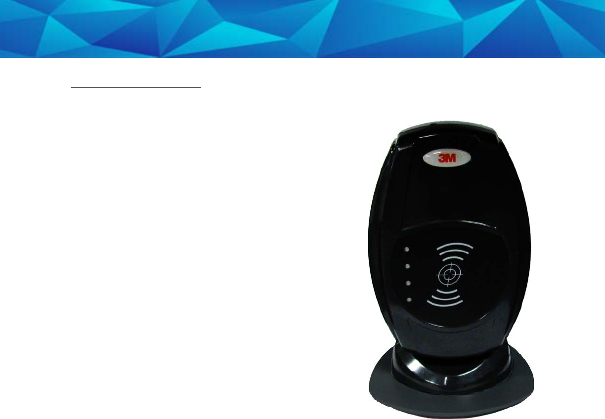
Beacon Overview
• Radio Frequency communication with 1 Piece
(Gen 4).
• Adjustable ranges: The default range between
the Beacon and the 1 Piece (Gen 4) is up to 150
feet (high). The range can be adjusted to
medium: up to 100 ft, and low: up to 50 feet.
All ranges are approximate and based on
environmental conditions.
• 24 Hour Backup Battery.
• Battery backup takes 4 hours to recharge.
• The Power LED indicates that the Beacon is on
and functioning properly.
• If the LED is not lit, the device has not received
power from a wall outlet for more than twenty-
four hours and the backup battery has died.
The device must be plugged in immediately.
• Motion Sensor.
16
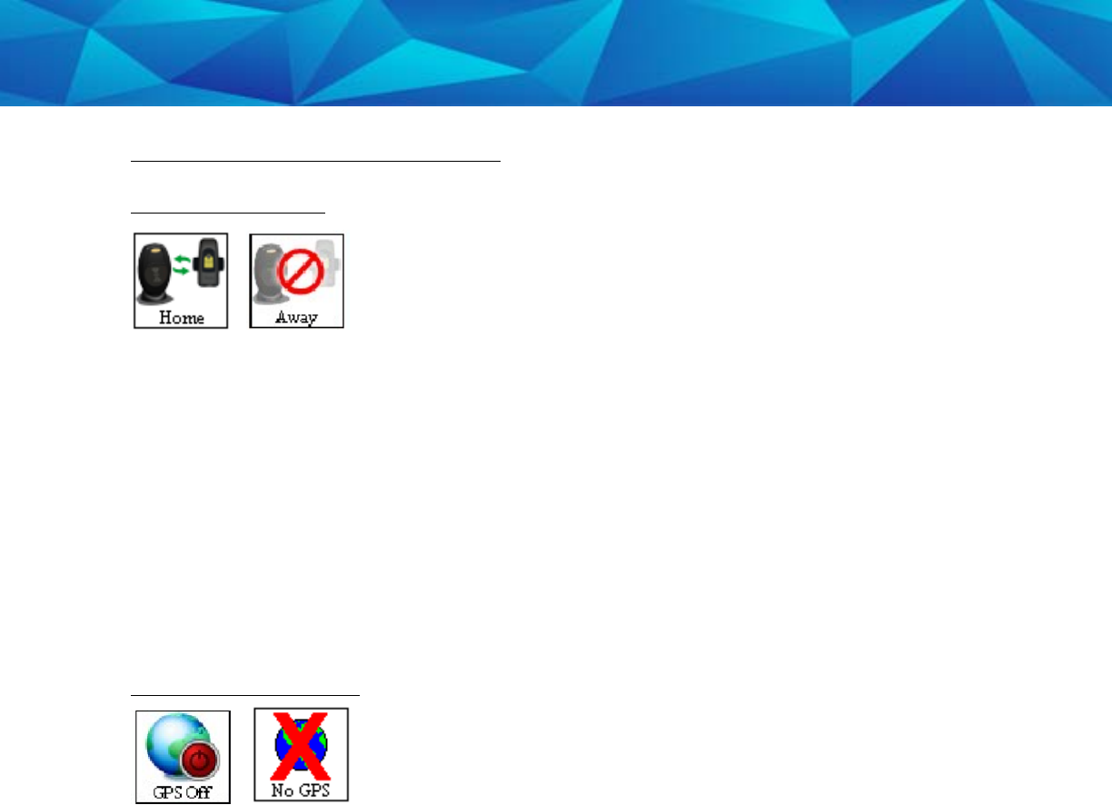
Beacon Operating Features
Home/Away Status
When the 1 Piece (Gen 4) is in range of the Beacon, it will start receiving signals from
the Beacon and will record a “Home” status. The 1 Piece (Gen 4) will remain in the
“Home” status until it is taken out of range of the Beacon.
When the 1 Piece (Gen 4) is taken out of range of the Beacon, it will stop receiving
signals from the Beacon. When the 1 Piece (Gen 4) is out of range for five consecutive
minutes, it will record an “Away” status.
Note: The “Home” status indicates that the 1 Piece (Gen 4) is within range of the
Beacon. The “Away” status indicates that the 1 Piece (Gen 4) is not within range of the
Beacon.
GPS Off/No GPS Icons
When the 1 Piece (Gen 4) is within range of the Beacon, in the “Home” Status, for two
consecutive minutes, GPS will be turned off. While GPS is turned off, an icon will
appear on the EM Manager (Smart View) map in place of the “No GPS” icon. The icon
will read “GPS Off.”
GPS will be reacquired when the offender moves out of range of the Beacon for one
minute or when a Base Location Un-trusted or A/C Power Loss violation has been
generated.
While the offender is in the “Away” status, if the offender loses GPS, the “No GPS”
icon will appear on the EM Manager (Smart View) map.

17
Beacon Operating Features, Cont.
A/C Power Loss/Base Location Un-Trusted
If the A/C Power or the Base Location Un-Trusted violations occur during the “Home”
status:
The 1 Piece (Gen 4)’s GPS will turn back on. After 60 minutes, the 1 Piece (Gen 4) will
check to see if the violation has been cleared. If the violation has cleared, the GPS will
turn off. If the violation has not cleared, the GPS will stay on and the 1 Piece (Gen 4)
will continue to check the status of the violation every hour until the violation clears.
18
Enrollment
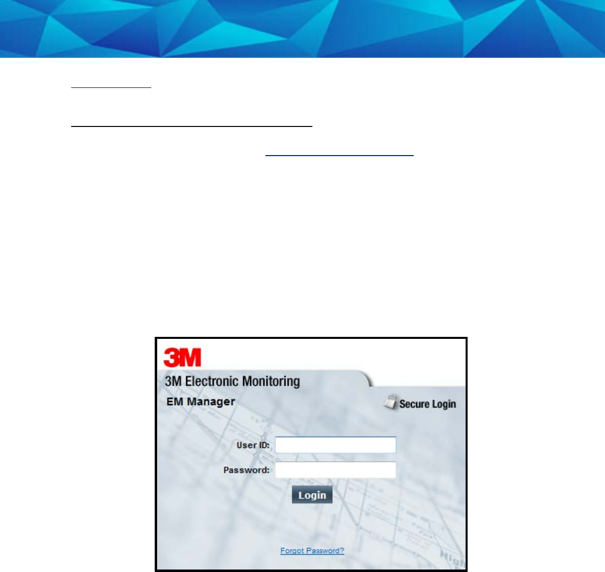
EM Manager (Smart View) Log In
To access the secure website, go to https://smartview.ptm.com. You will be required
to enter a user ID and password. When using EM Manager (Smart® View) for the first
time, you will create your own password. Enter your User ID (often your three initials
and last four digits of your social security number), the temporary password that was
emailed to you, and click OK. The next screen will tell you that your password has
expired. Create your password, (the password you select must contain at least 8
characters), and click OK. You will now be logged into EM Manager (Smart View.)
Note: If you forget your password, click the
Forgot your Password
link. A new
temporary password will be emailed to you. To create your new password, follow the
instructions contained within the email.
19
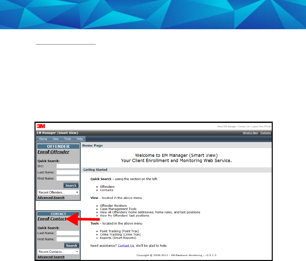
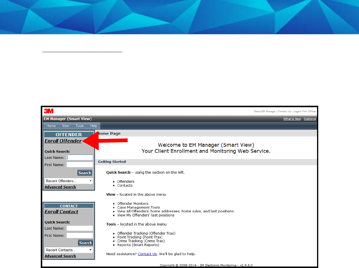
Enroll a Contact
The
Enroll Contact
link is located on the left side of the Home page (see below). It is
here that you will enter the officer’s information (name, address, phone number, etc.),
report types, and default notification settings.
1. Click the
Enroll Contact
link on the left side of the Home page.
2. You will be redirected to the Enroll Contact page (see below). Enter all Contact
information.
3. Click Save.
20
Enroll a Contact, Cont.

21
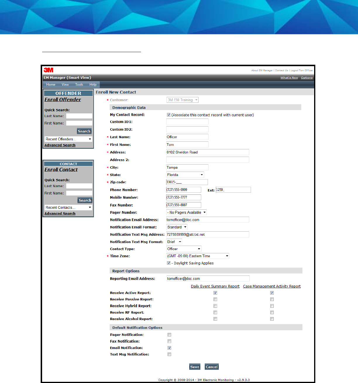
Enroll a Contact, Cont.
Demographic Data
1. Enter the Contact’s information.
• All fields with red asterisks (*) are required fields.
Report Options
2. Enter an email address where the selected reports will be sent.
3. Choose Daily Violation Summary Report and/or Case Management
Activity Report.
Default Notification Options
4. Select the type of Notification you would like to be your default method.
The notification method is dependent upon the information that you
enter into the Notification Email or Text Message fields.
• Pager
• Fax
• E-mail
• Text Message
Finish Enrollment
5. When you have completed the form, click Save.
22
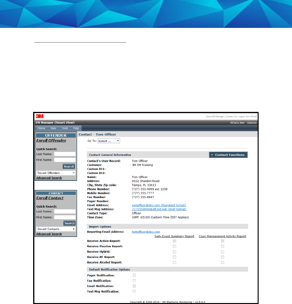
Contact Information Page
When you click Save, you will be taken to the Contact Information page (see below).
Here, you can edit the contact information, as well as disable the contact.
1. To edit the contact information, move your cursor over the Contact Functions
menu and left click Edit.
2. To disable the contact, move your cursor over the Contact Functions menu and
left click Disable Contact.
23
Enroll an Offender
The
Enroll Offender
link is located on the left side of the Home page (see below).
1. Click the
Enroll Offender
link.
24
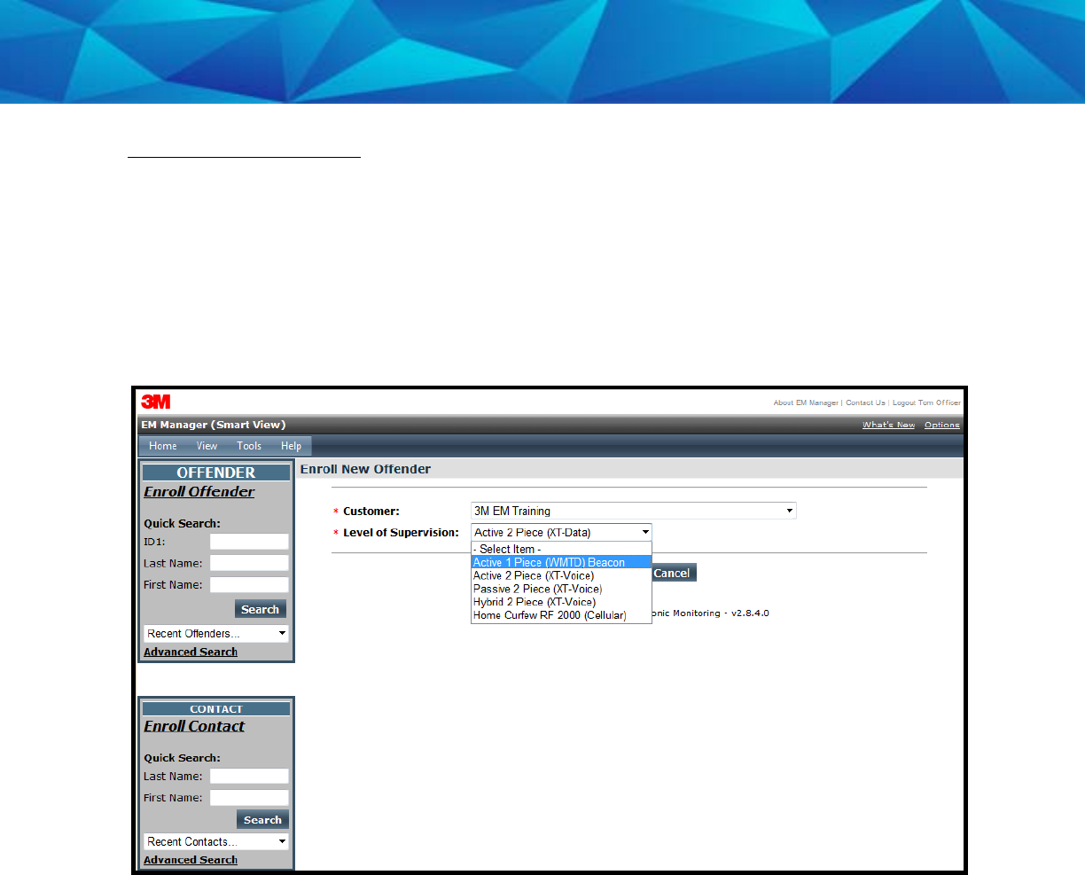
Supervision Level
Clicking on the
Enroll Offender
link will redirect you to the Level of Supervision page
(see below).
1. Click on the Level of Supervision drop down menu.
2. Select “1 Piece (Gen 4) w/ Beacon” as the Level of Supervision (see below).
3. Click the Continue button.
25
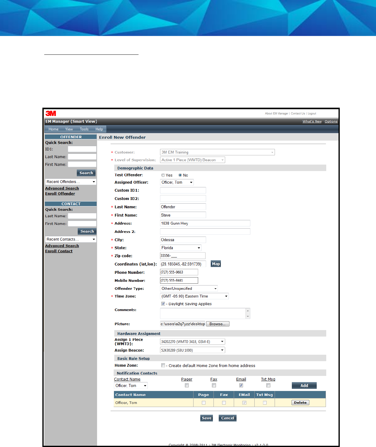
Offender Enrollment
After selecting the Level of Supervision, you will be redirected to the Enroll Offender
page (see below). It is here that you will select an Assigned Officer, enter the
Offender’s Information, select the Notification Contact and Method, Assign Hardware,
and select the Basic Rule Setup.

26
Offender Enrollment, Cont.
Demographic Data
1. Enter the Offender's Information.
• All fields with red asterisks (*) are required fields
2. Click the Map button to geo-code the offender’s address.
3. Select the Offender Type.
4. Select the Time Zone.
Hardware Assignment
5. Locate the serial number on the device(s).
6. Click on the drop down menu and select that serial number for the
device.
Basic Rule Setup
7. Do NOT check the box next to Home Zone in the Basic Rule Set Up. No
home zone is needed if a Beacon is being utilized.
8. Choose the appropriate Contact from the Notification Contact drop
down list. The selected Contact will be notified for all rules.
9. Click the Add button.
10. Select the type of Notification (if you haven’t chosen your Default
Notification Method on your Contact record)
• Pager
• Fax
• E-mail
• Text Message
Finish Enrollment
11. When you have completed entering the information, click Save.
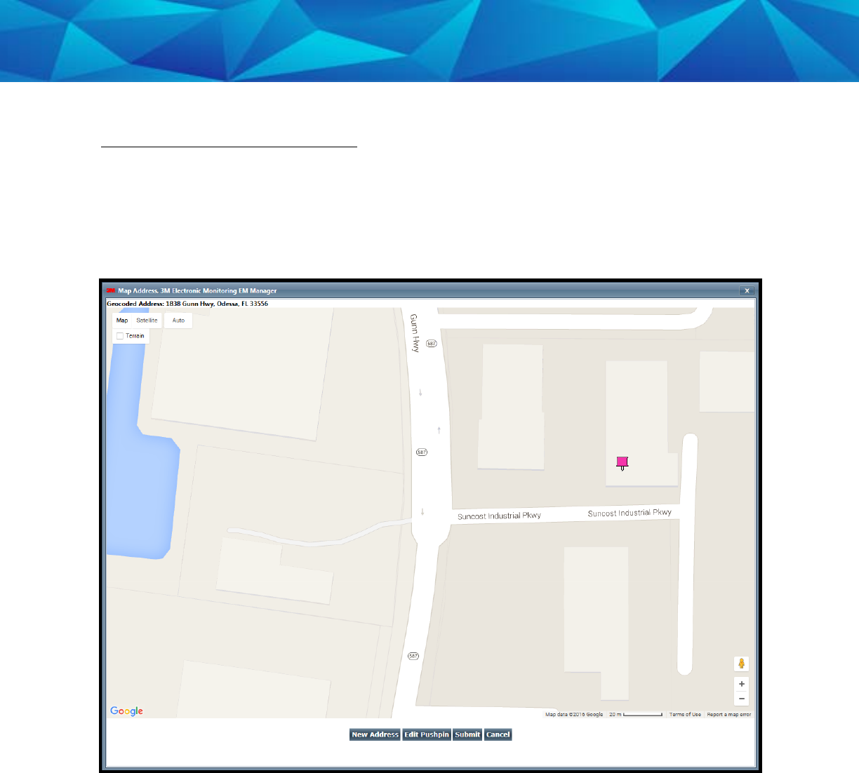
27
Map Offender’s Address
Clicking the Map button on the Offender Enrollment screen will generate a map that
displays a pushpin at the offender’s residence. Ensure that the pushpin location is
correct and click the Submit button. It is also possible to edit the location by clicking
the Edit Pushpin button.
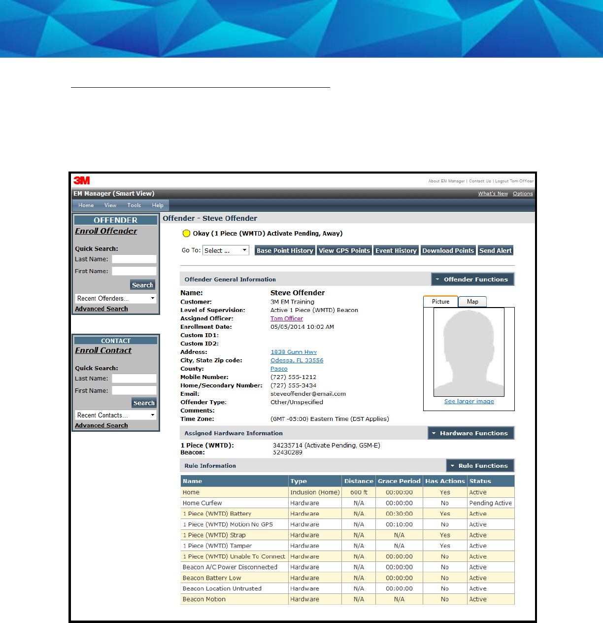
28
Offender General Information Page
When Enrollment has been completed, you will be redirected to the Offender General
Information page (see below). Here, you can Edit Offender Information, Disable the
Offender, View GPS Points, Unassign Hardware, Edit Rules, Send Alerts, and
Download Points.
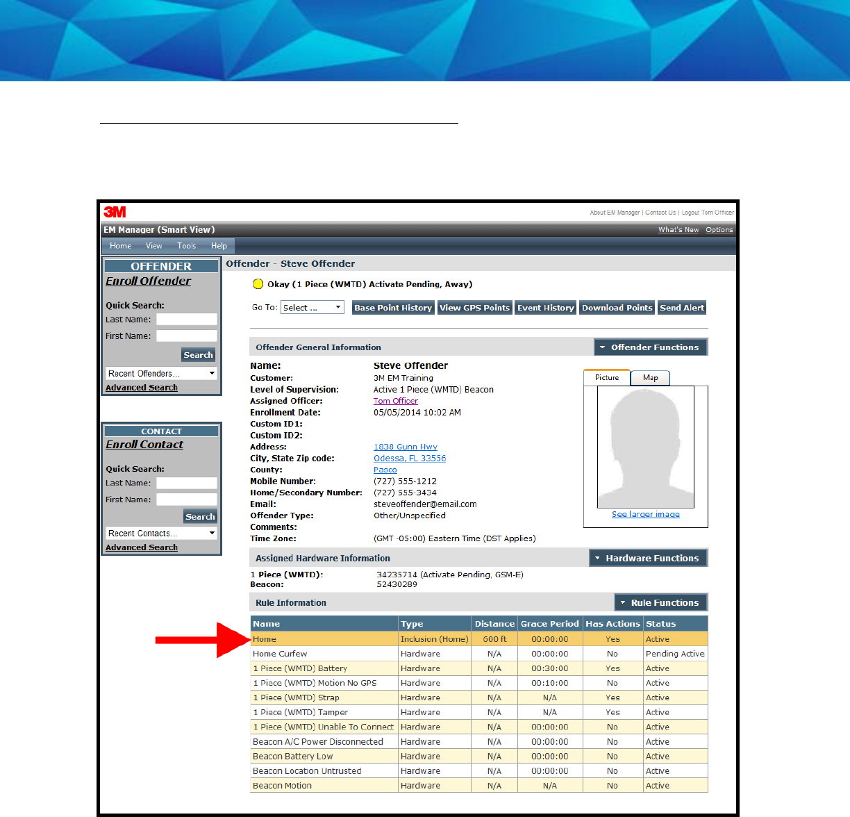
29
Create Schedule for Home Curfew
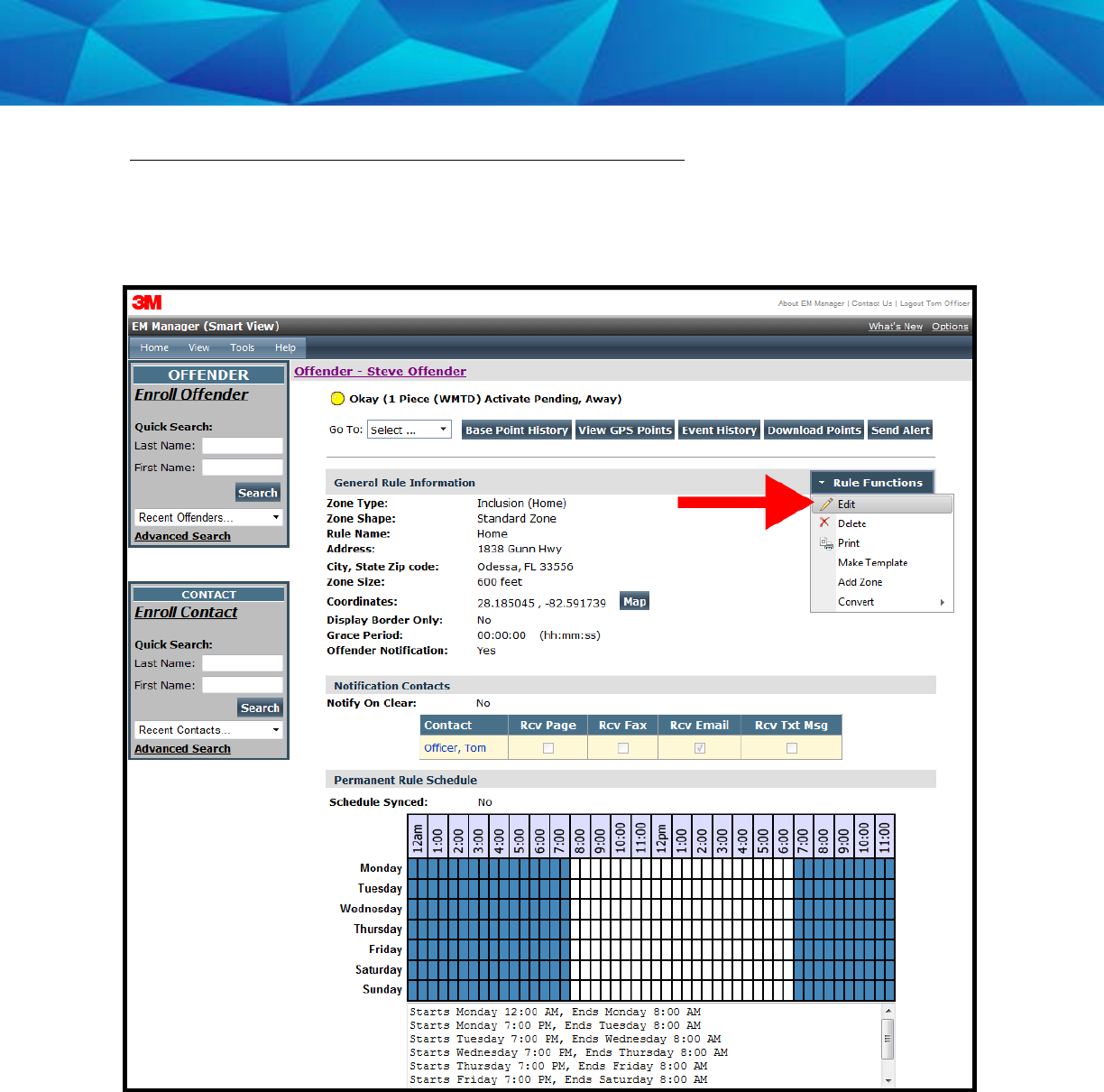
1. Click on the Home Curfew Rule (see below).
30
Create Schedule for Home Curfew, Cont.
2. Move your cursor over the Rule Functions menu and left click Edit.
31
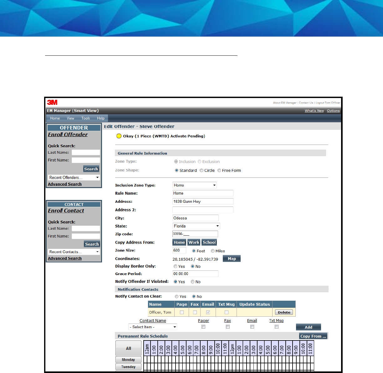
Create Schedule for Home Curfew, Cont.
3. You will be redirected to the Edit Rule page. Scroll down to the Permanent Rule
Schedule.
32
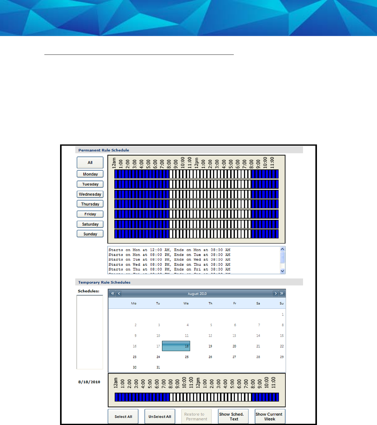
Create Schedule for Home Curfew, Cont.
4. Each block represents a 30 minute increment of time. Left-click and drag the
cursor along the blocks during the times that the offender is required to be
home. As you move the cursor, the blocks will turn blue. The white blocks that
remain equal the times that the offender is allowed to be out of the home (see
below).
5. Click the Save button.
33
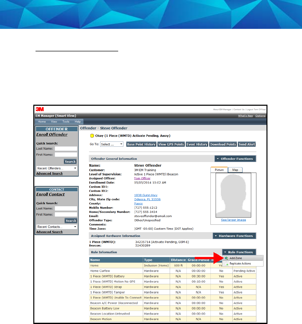
Create Exclusion Zone
You can create an Exclusion Rule to ensure that the offender is not entering areas
which are forbidden – such as schools, playgrounds, and victims’ residences.
1. Move your cursor over the Rule Functions menu (see below).
2. Left click Add Zone.
34
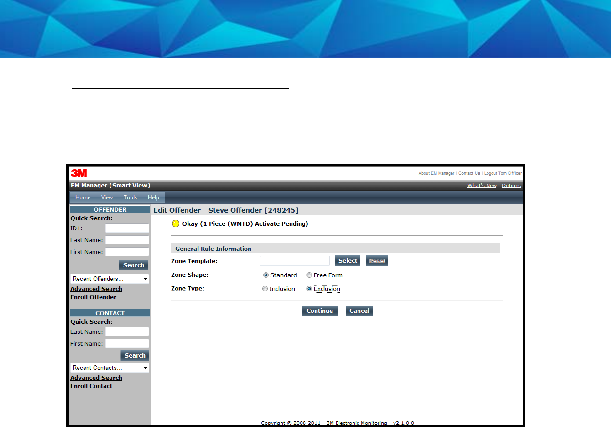
Create Exclusion Zone, Cont.
3. Choose a Zone Shape.
4. Choose Exclusion as the Zone Type.
5. Click the Continue button.
35
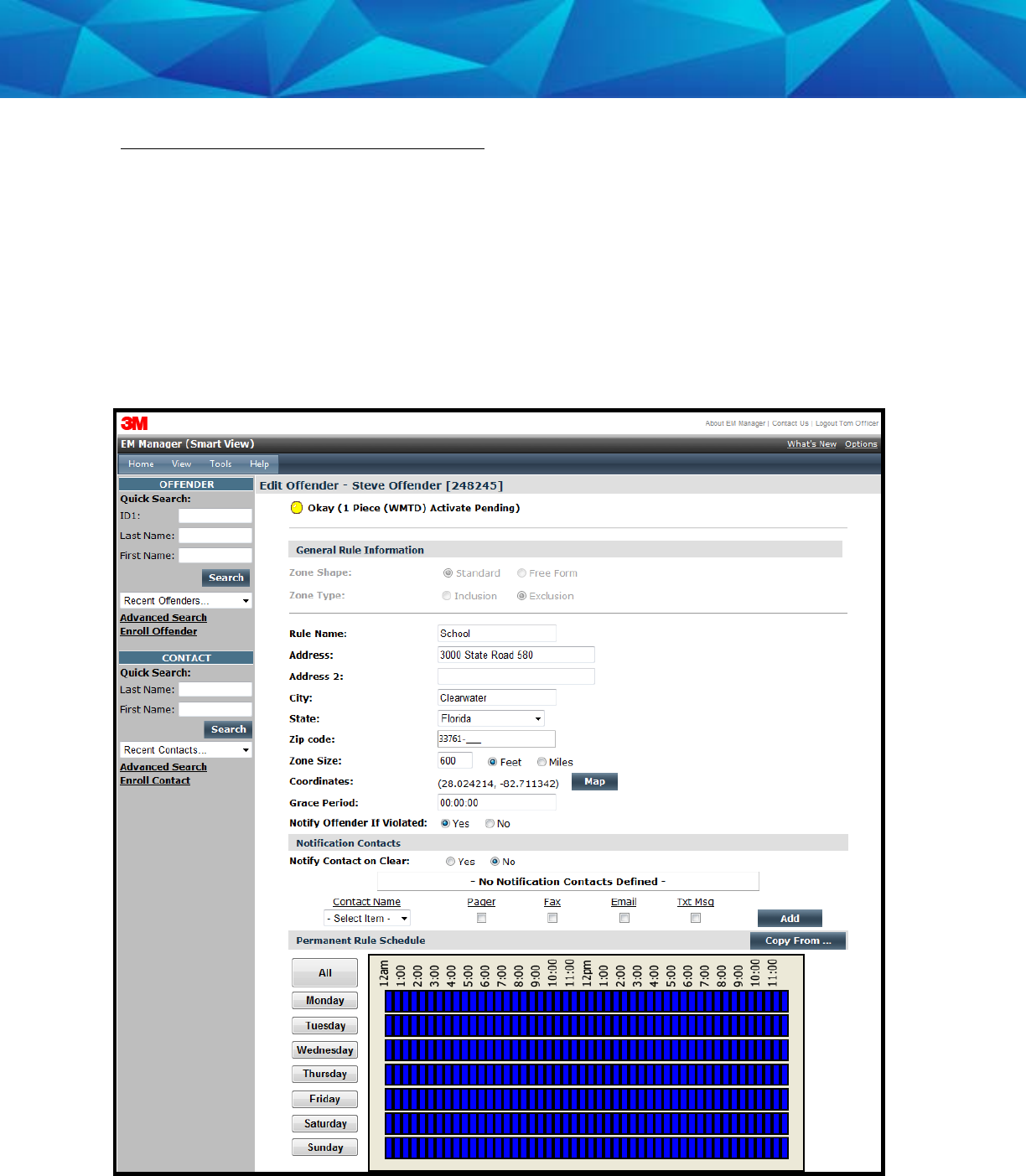
Create Exclusion Zone, Cont.
6. Enter the Rule Name (school, playground, etc.).
7. Enter the address information and the zone size. The default is 600 ft.
8. Select
Yes
or
No
if you want to notify the offender upon violation.
9. Choose the appropriate Contact from the Notification Contact drop down list.
The contact’s default notification method will appear selected.
10. Click the Add button.
11. Click the Map button.
36
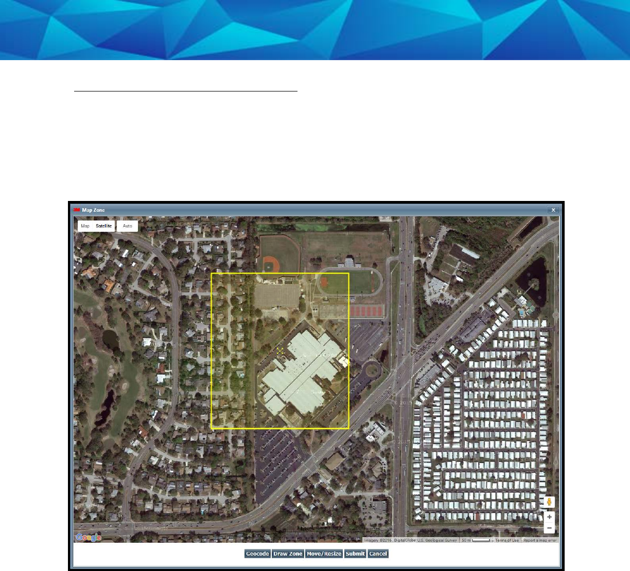
Create Exclusion Zone, Cont.
12. Ensure that the address and zone size is correct.
13. If you want to resize or move the zone, click the Move/Resize button.
14. If you move or resize the zone, click the Finish Move/Resize button.
15. Click the Submit button.
37
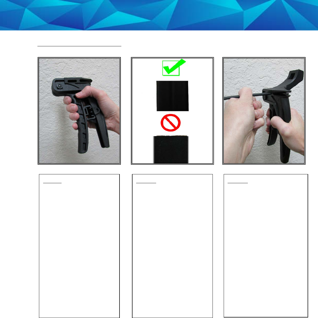
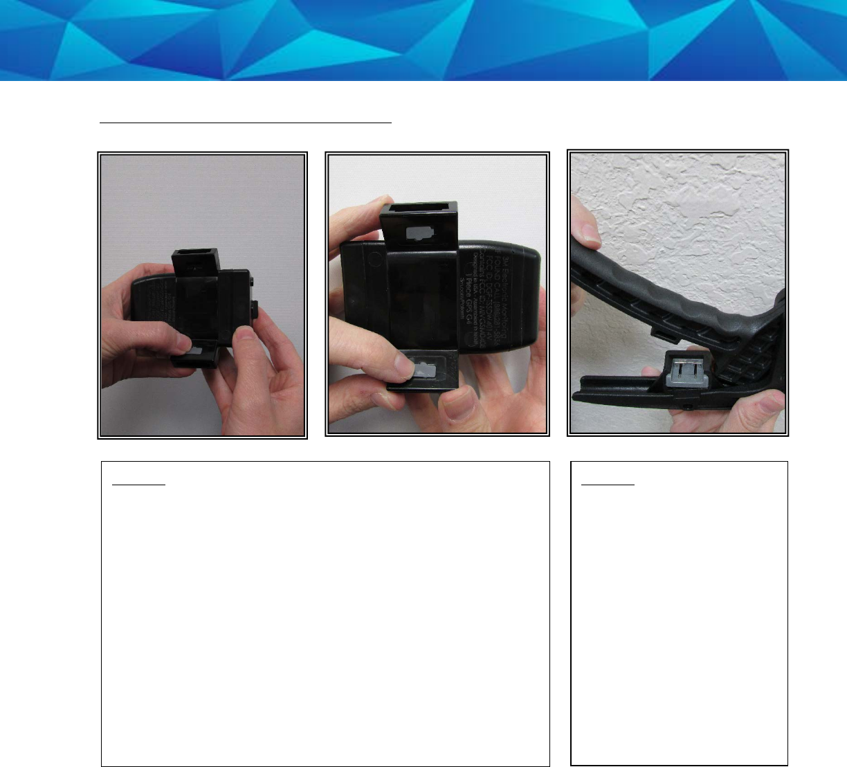
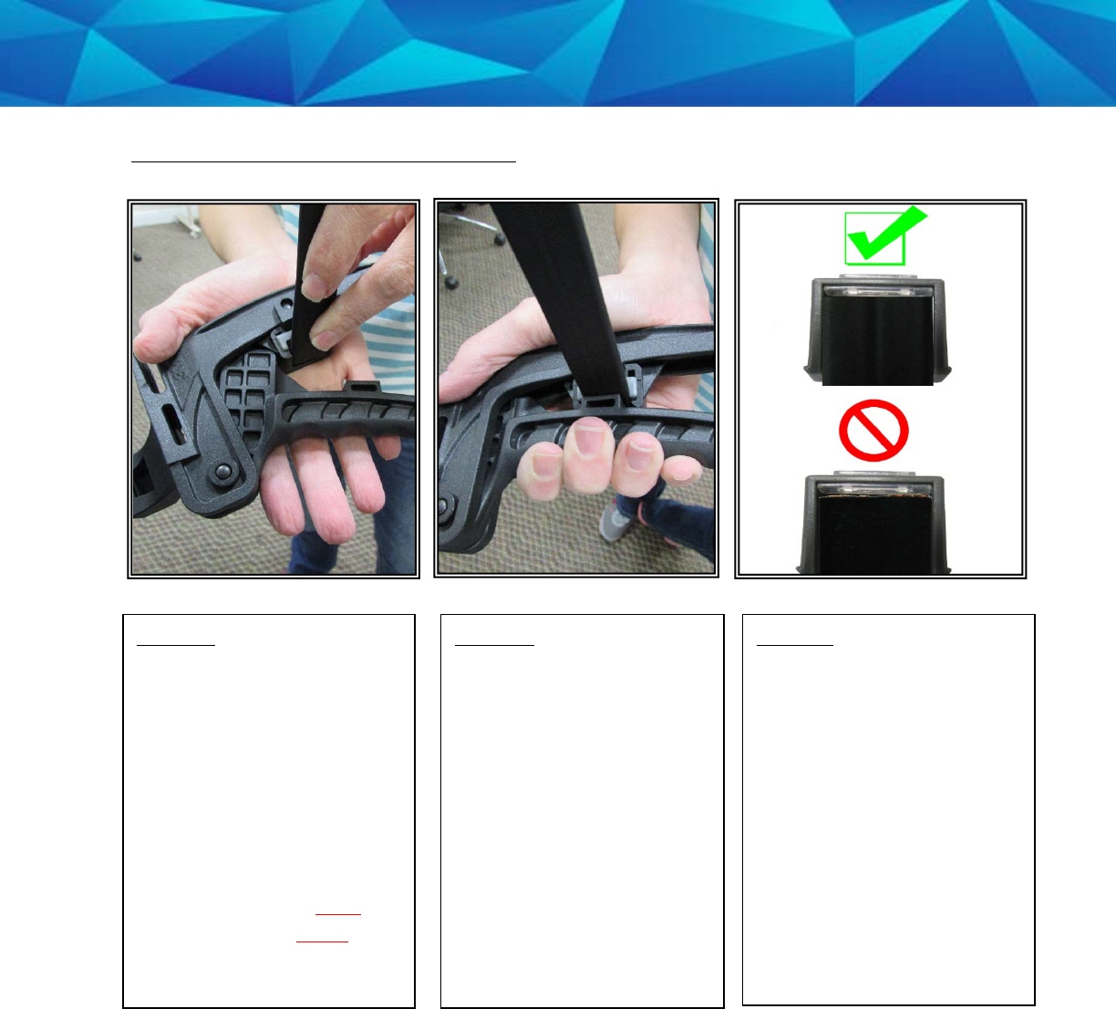
Attaching the (Gen 4)
Step 2:
Examine both ends of the
strap to ensure that the
strap has been cut
evenly. If the strap has
been cut at an angle or
the copper/fiber optic
cable is protruding,
proceed with step 3. If
both ends of the strap are
cut evenly and there is no
visible protrusion,
proceed with step 4.
Step 1:
Place your four fingers on
the finger grip and your
palm on the palm grip.
Step 3:
Spread the handles of the
strap installation tool and
insert the uneven end of
the strap into the
measuring slot. Push the
strap in until the edge of
the strap is at the edge of
the slot (see above).
Squeeze the handles
together to cut the end of
the strap.
Keep the handles together,
tilt the strap installation
tool, and tap out the cut
piece of strap.
38
Attaching the (Gen 4), Cont.
Step 4:
Push the tamper plugs into the back brackets of the
device. Be sure to enter the right side first. After the right
side has been secured, repeat the process on the left
side.
Step 5:
Spread the handles of the
strap installation tool and
insert the pin tray into the
slot located on the handle
(see above). Push the pin
tray in until it stops.
Note: The metal pins
should be facing up and
the silicone plug should
be under the lip of the
slot.
39
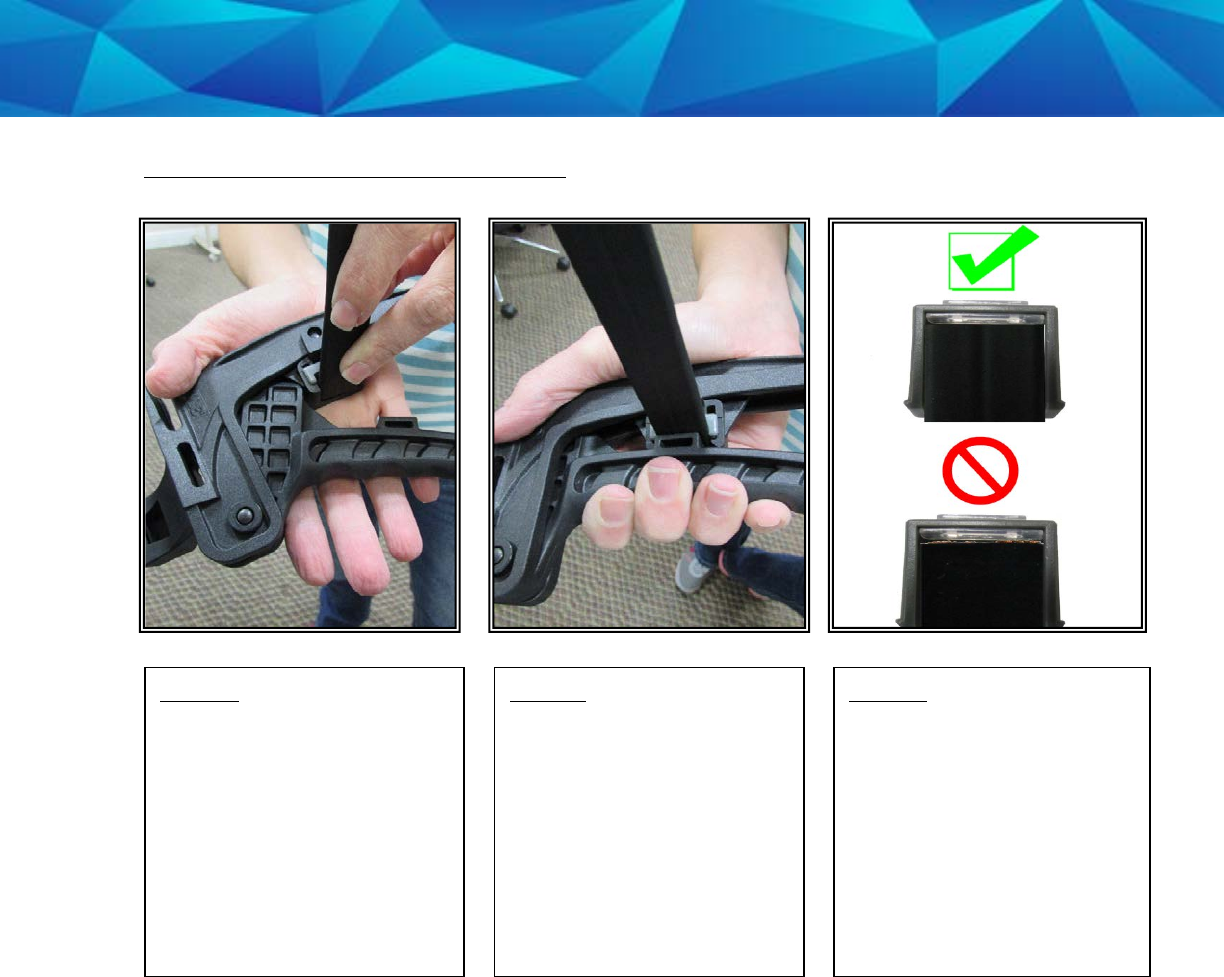
Attaching the (Gen 4), Cont.
Step 6:
Lay the strap installation
tool in the palm of your
hand. Place the strap over
the pin tray and ensure
that the end of the strap is
touching the lip of the pin
tray slot.
Step 7:
Squeeze the handles
together until the strap is
firmly attached to the pin
tray.
Step 8:
Examine the end of the
strap to ensure that the
edge is even with the
silicone plug and that no
gaps are visible.
40
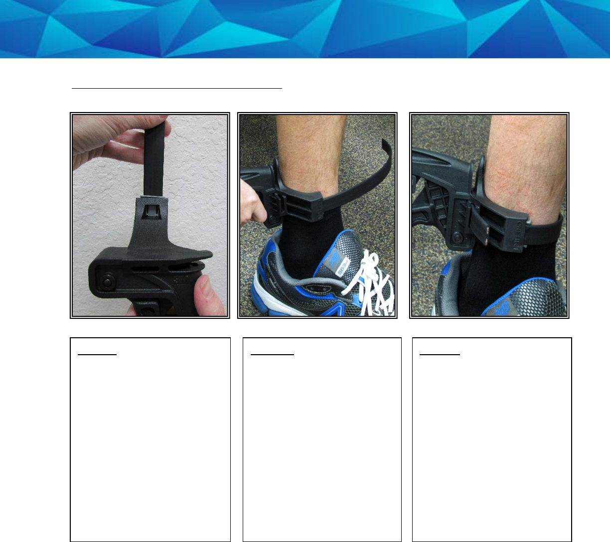
Attaching the (Gen 4), Cont.
Step 10:
Place the tool on the
offender’s ankle.
Note: Ensure that the
strap is at the front or the
back of the leg.
Step 11:
Insert the free end of the
strap into the strap slot
(see above) and push it
through to the other side.
Left-handed users: Use
your right hand to hold the
strap installation tool and
your left hand to insert the
strap into the measuring
slot.
Step 9:
Insert the strap and pin
tray into the second pin
tray slot location on the
top of the strap installation
tool.
41
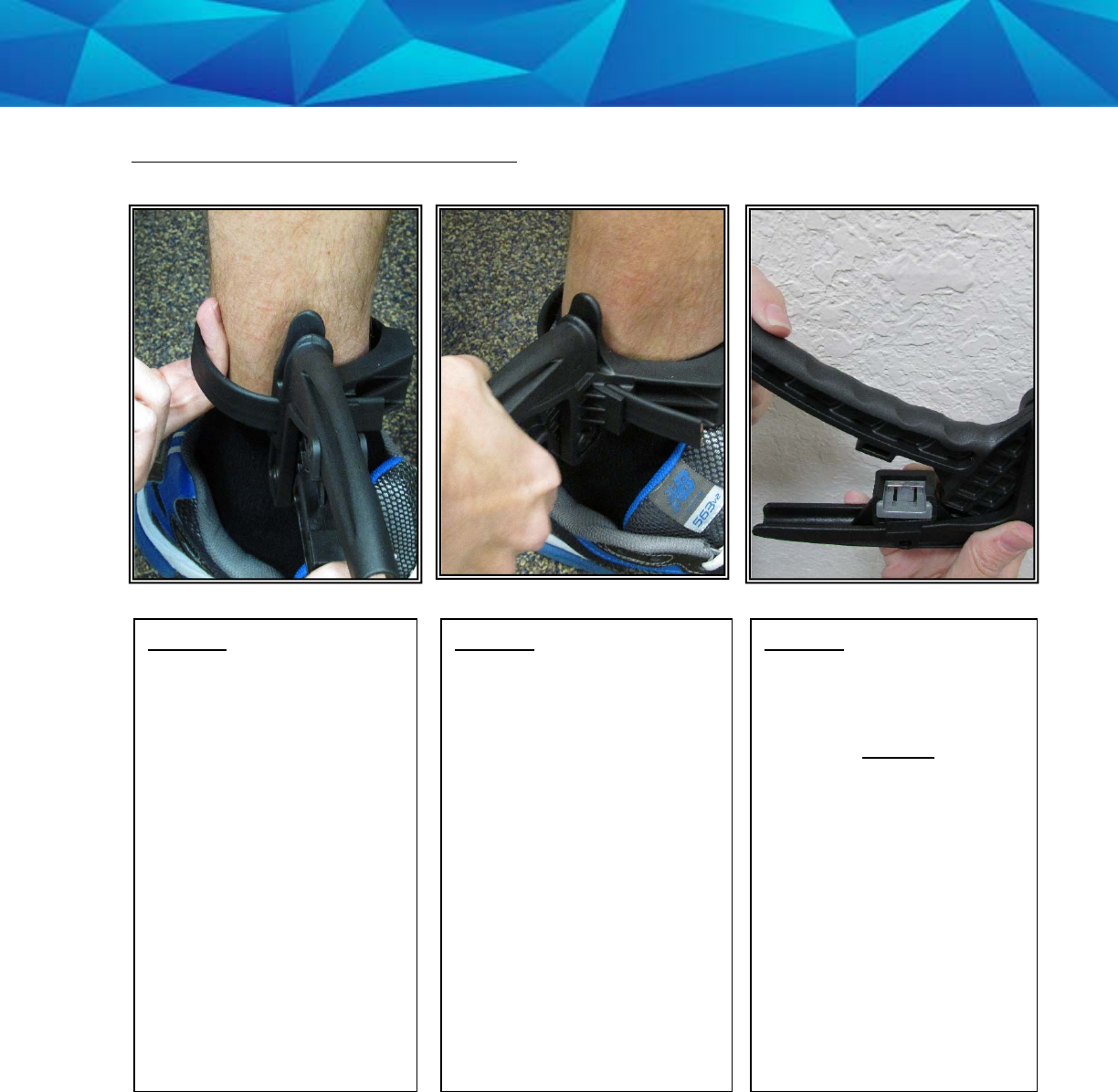
Attaching the (Gen 4), Cont.
Step 13:
Cut the strap by
squeezing the two handles
of the strap installation
tool firmly.
Step 12:
Allow approximately half
an inch between the
strap and the offender’s
leg. This can be done by
inserting two fingertips
until the first knuckles are
under the strap.
Left-handed users: Hold
the strap installation tool
with your left hand and
use the fingertips of your
right hand to measure the
half inch spacing.
Step 14:
Spread the handles of the
strap installation tool and
insert the second pin tray
into the slot located on
the handle (see above).
Push the pin tray in until it
stops.
Note: The metal pins
should be facing up and
the silicone plug should
be under the lip of the
slot.
42
Attaching the (Gen 4), Cont.
Step 15:
Lay the strap installation
tool in the palm of your
hand. Place the strap over
the pin tray and ensure
that the end of the strap is
touching the lip of the pin
tray slot.
Note: Ensure that both pin
trays are on the same side
of the strap.
Step 16:
Squeeze the handles
firmly together until the
strap is firmly attached to
the pin tray.
Step 17:
Examine the end of the
strap to ensure that the
edge is even with the
silicone plug and that no
gaps are visible.
43
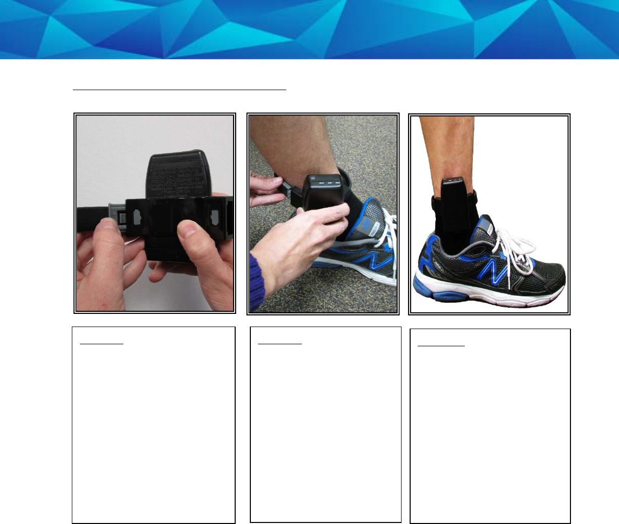
Attaching the (Gen 4), Cont.
Step 20:
Wrap the strap around the
offender’s ankle and insert
the other end of the strap
and pin tray into the
remaining bracket until it
snaps in place. Pull on the
strap to ensure that the
device is secured to the
offender’s ankle.
Step 19:
Place the device on the
offender’s leg – just
above the ankle bone.
Step 18:
Insert one end of the strap,
with attached pin tray, into
the bracket.
44
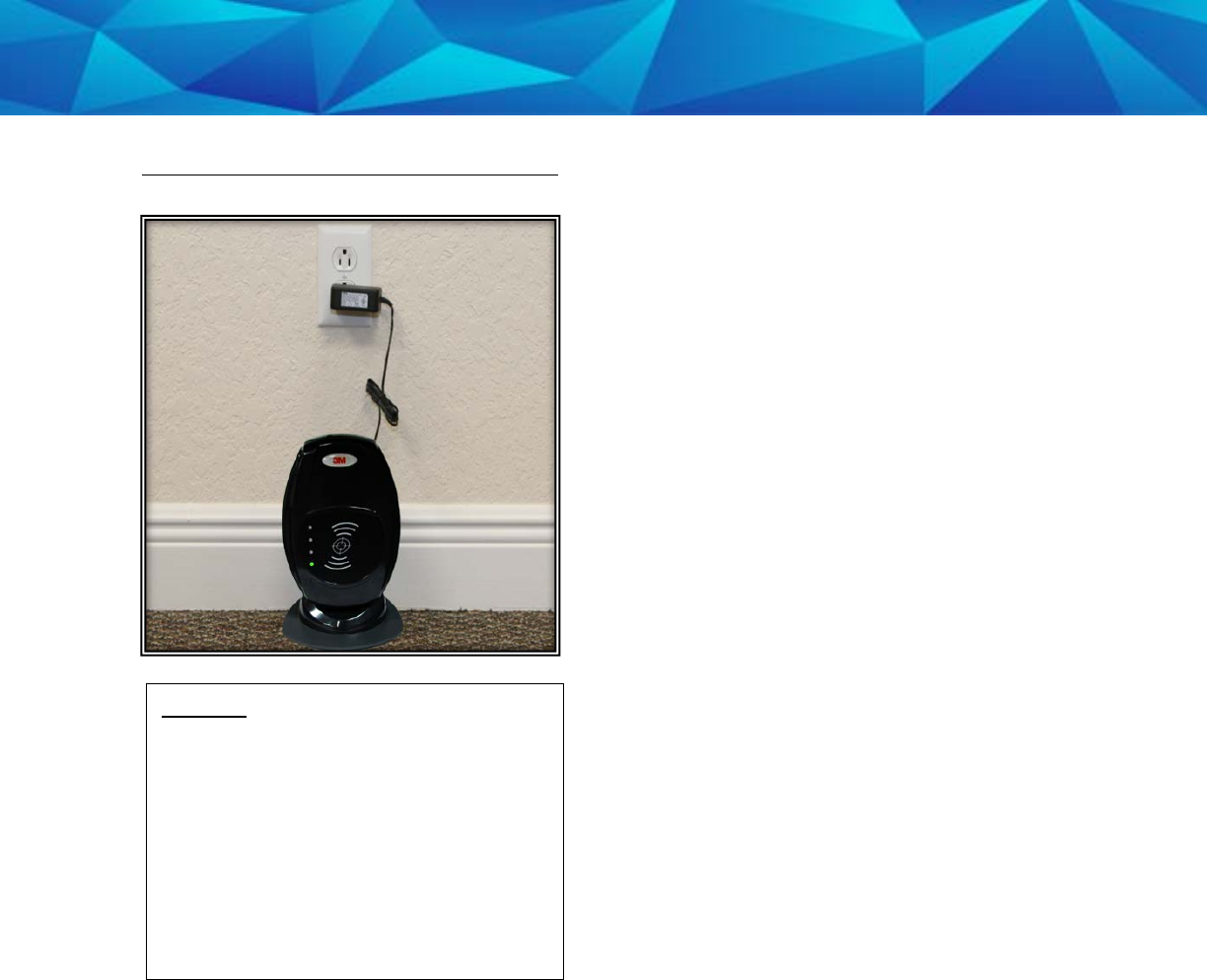
Attaching the (Gen 4), Cont.
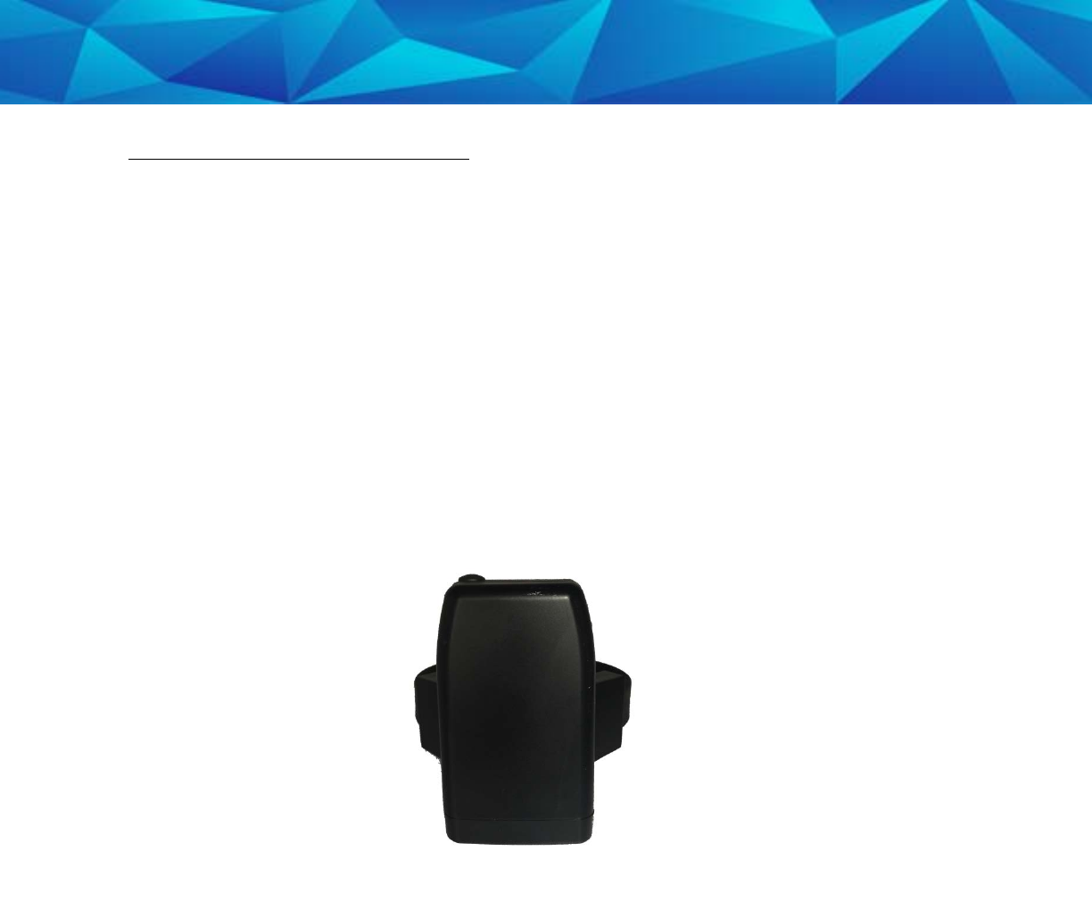
Step 21:
Plug the Beacon’s attached A/C
adapter into a wall outlet. Be sure to
place the Beacon on a hard surface
in an area where it will not be
moved frequently. Unnecessary
movement will likely trigger one or
more violations.
45
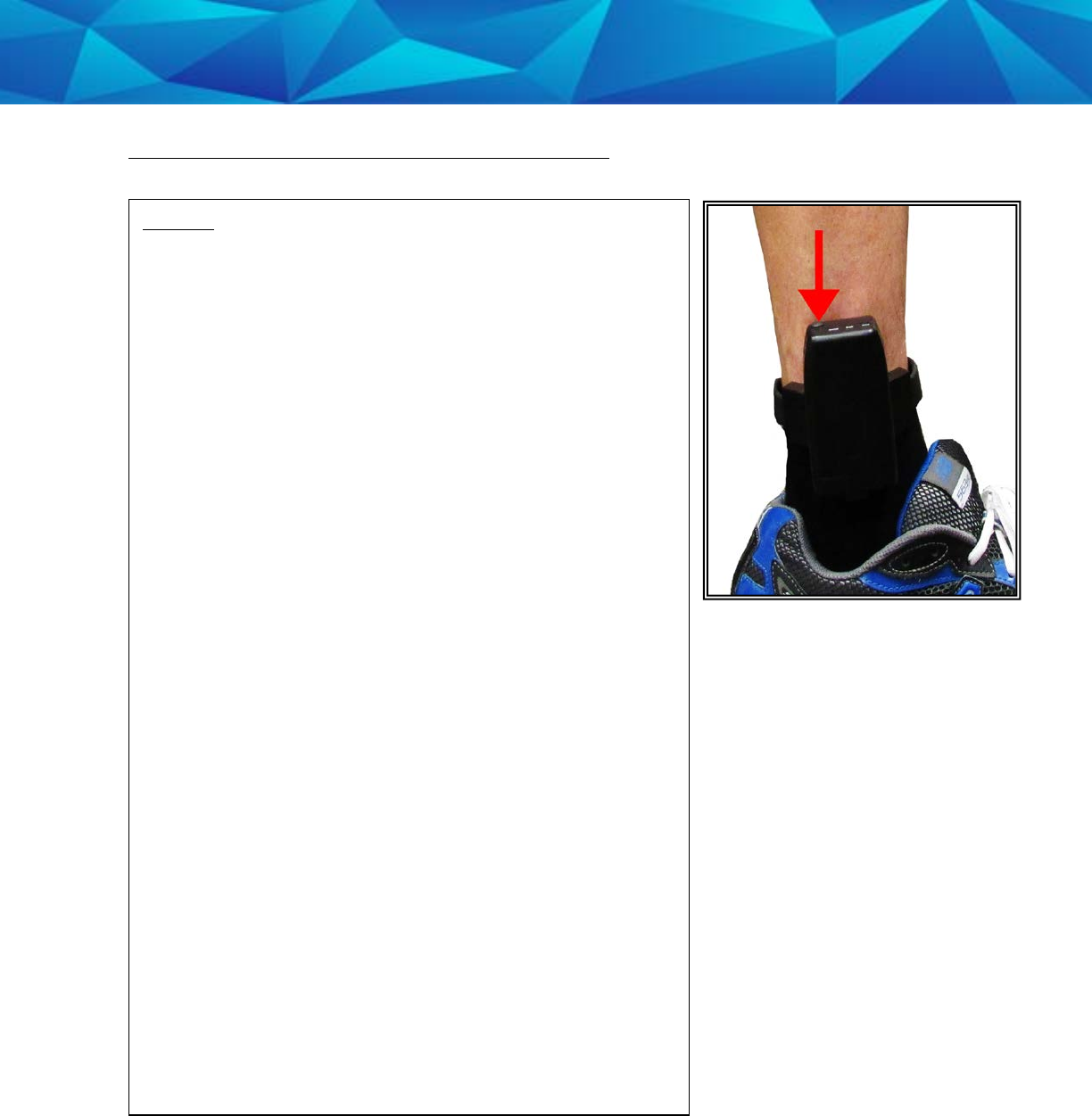
Activating the 1 Piece (Gen 4), Cont.
.
Step 11:
Press and hold the Activate Button on the top of the 1
Piece (Gen 4) for three seconds.
A. The 1 Piece (Gen 4) will vibrate once and the “PWR”
LED will begin to blink green, indicating the 1 Piece
(Gen 4) is powered on.
B. The “GPS” and “ZONE” LED’s will blink green once
every second. This indicates that the 1 Piece (Gen 4) is
attempting to make a wireless call.
C. The “GPS” and “ZONE” LEDs will blink green twice
every second. This indicates that the 1 Piece (Gen 4) is
attempting to acquire GPS. The 1 Piece (Gen 4) must
now be taken outside to acquire GPS.
D. The “GPS” and “ZONE” LED’s will then blink green
three times every second. This indicates that the 1
Piece (Gen 4) is attempting to communicate with the
Beacon. The offender will be required to move in range
of the Beacon in order to complete the activation
process. The 1 Piece (Gen 4) will vibrate 3 times when
activation is complete.
Note: If no Beacon is present, it will still be possible to
activate the 1 Piece (Gen 4) by holding down the
activation button for approximately five seconds while
the “GPS” and “ZONE” LEDs blink three times. The 1
Piece (Gen 4) will vibrate 3 times when activation is
complete.
46
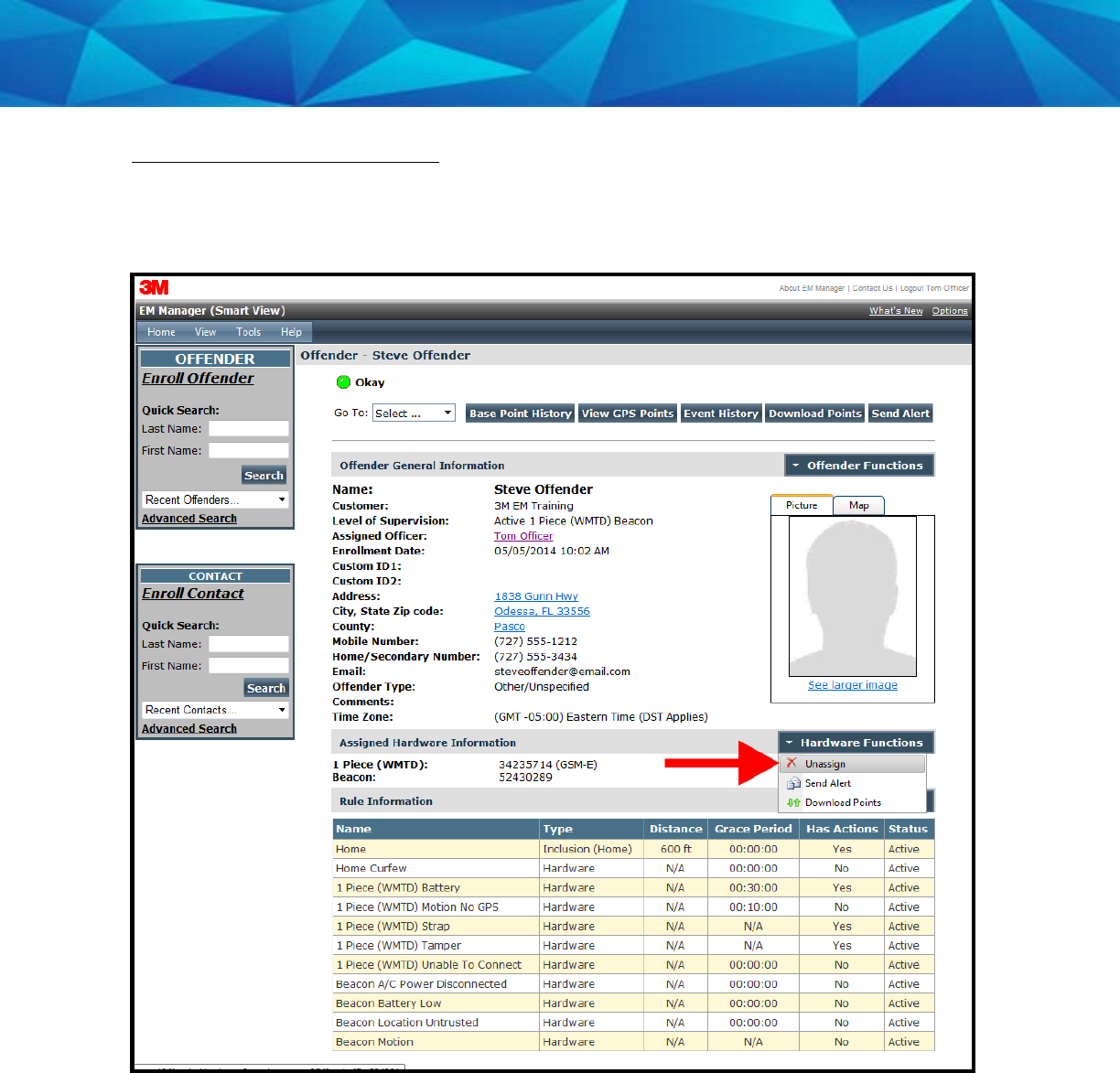
Unassigning Hardware
1. Move your cursor over the Hardware Functions menu and left click Unassign.
47
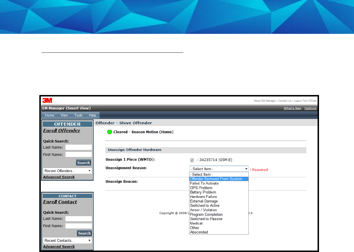
Unassigning Hardware, Cont.
2. Click the checkbox next to the 1 Piece (Gen 4) and Beacon (see below).
3. Click on the drop-down menu and select an Unassignment Reason. This is required.

48
Unassign Hardware, Cont.
4. Click the Save button. A popup will generate with a warning that the unassignment
is immediate.
5. Click OK.
49
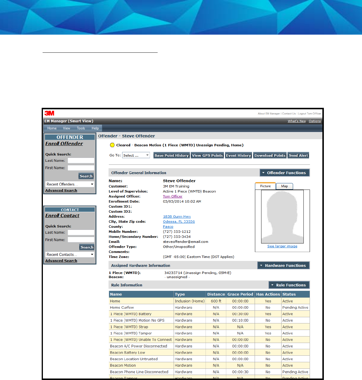
Unassign Hardware, Cont.
6. You will be returned to the Offender Information page, where the Beacon will be
unassigned and the 1 Piece (Gen 4) will be pending unassignment. The 1 Piece (Gen
4) is now required to call 3M Electronic Monitoring and transmit its final data. It
will only be unassigned once this final call has occurred.
50
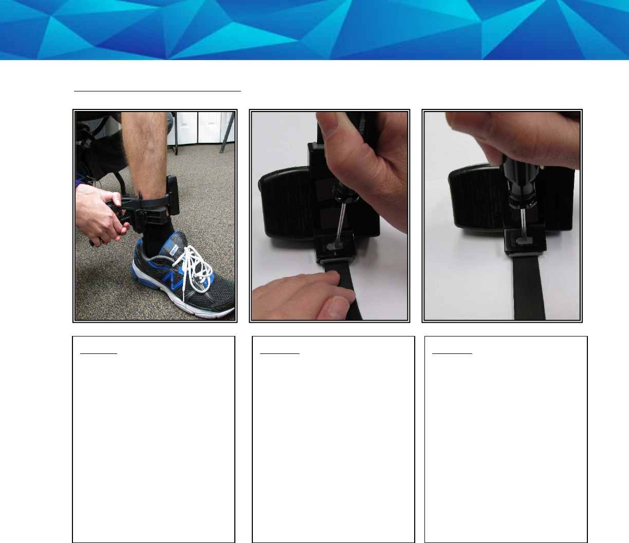
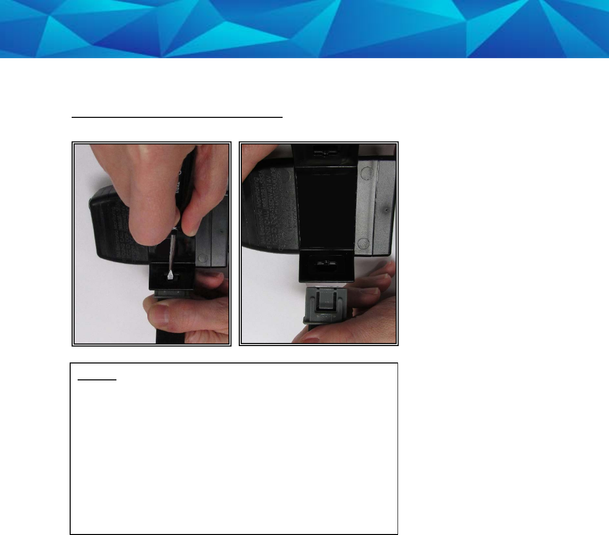
Removing the (Gen 4)
Step 1:
Spread the handles of the
strap installation tool and
cut the strap by sliding
the tool upwards until the
strap is positioned inside
the strap removal slot (see
above). Squeeze the
handles firmly until the
strap is cut.
Step 2:
Use a flathead
screwdriver to push on
the tamper plugs and
break them.
Step 3:
Use the screwdriver to
remove the tamper plugs
by pressing down on the
release latch inside the
bracket.
51
Removing the (Gen 4), Cont.
Step 4:
Keep the release latch depressed as you pull the strap
with attached pin trays out of each bracket. Discard the
tamper plugs, pin trays, and straps.
Note: Do NOT reuse the tamper plugs.
Note: Do NOT remove tamper plugs from the brackets of
the device unless there is a strap with an attached pin tray
inside the bracket.
52
1 Piece (Gen 4) SELF TEST
To Begin the 1 Piece (Gen 4) Self Test:
• Make sure the 1 Piece (Gen 4) is unassigned from any offenders
• Make sure the 1 Piece (Gen 4) does NOT have a strap with a pin tray in it
• Make sure that the 1 Piece (Gen 4) is in a good wireless and GPS location
• Press and hold the Activate Button until the 1 Piece (Gen 4) vibrates (about 5
seconds)
• The PWR/ZONE/GPS LEDs will begin to blink green, verifying the test is in
progress
• Only the Zone and GPS LEDs will be utilized for the test
• The test results will be displayed on the Zone/GPS LEDs within 10 minutes
• To stop the test, press and hold the Activate button until it vibrates
.
Test Results:
• ZONE/GPS LED solid green = passed all tests.
• ZONE/GPS LED blinking red ONE time = Modem Failure.
• ZONE/GPS LED blinking red TWICE = GPS Failure.
• ZONE/GPS LED blinking red THREE times = Tamper Failure.
• The test results will be displayed on the Zone/GPS LEDs for one hour.

53
Appendix
Rule Definitions
Home/Away Status
• When the 1 Piece (Gen 4) is in range of the Beacon, it will start receiving
signals from the Beacon. When these signals are received by the 1 Piece
(Gen 4), it will record a “Home” status. Likewise, when the 1 Piece (Gen 4) is
unable to receive signals from the Beacon for five consecutive minutes, it
will record an “Away” status. This indicates the 1 Piece (Gen 4) is out of
range of the Beacon.
Home Curfew
• If the 1 Piece (Gen 4) has a home schedule set and the 1 Piece (Gen 4) is not
in range of the Beacon during this time, a curfew alarm will be generated.
Note: The curfew alarm will not occur until a five minute internal buffer and
any user added grace period has expired. The device will vibrate three
times consecutively, and once every ten minutes thereafter, while in
violation if the Notify with Vibrate feature is checked. The Zone LED will
blink red until the violation is cleared.
1 Piece (Gen 4) Battery
• The battery is getting low and the device needs to be charged. The device
must be charged for a minimum of two hours daily (the hours do not have to
be consecutive). When the battery needs to be charged, the device will
vibrate three times consecutively and then once every ten minutes until it is
connected to the charger. During this time, the Power LED will blink red.
Motion No GPS
• The 1 Piece (Gen 4) has accumulated 20 minutes of motion in a 60 minute
period without receiving a signal from the GPS satellites. The device will
vibrate three times consecutively, and once every ten minutes thereafter,
until the violation has cleared by acquiring GPS. During this time, the GPS
LED will blink red until the violation is cleared.

54
Violations and Definitions, Cont.
1 Piece (Gen 4) Strap
• The strap has been compromised or removed from the 1 Piece (Gen 4).
There will not be any notification to the offender that this has occurred
unless the officer selects the Notify Offender with Vibrate option on this
rule.
1 Piece (Gen 4) Unable to Connect
• The 1 Piece (Gen 4) has a defined call-in interval that is determined by the
contract. If the 1 Piece (Gen 4) is unable to call 3M Electronic Monitoring at
its defined call-in interval, a default 90 minute grace period will go into
effect. If the default 90 minute grace period expires and the 1 Piece (Gen 4)
has still not called 3M Electronic Monitoring, the database will create this
alarm. This is normally due to poor cellular coverage in the area. The
offender is not notified of the Unable to Connect alarm. Once the 1 Piece
(Gen 4) is able to use the cellular network to call in, it will report any alarms
that occurred during this time and download all tracking data.
1 Piece (Gen 4) Tamper
• The 1 Piece (Gen 4) has been compromised in some form. There will not be
any notification to the offender that this has occurred unless the officer
selects the Notify Offender with Vibrate option on this rule.

55
Appendix
Geographic Rules
Zone Rules- The offender has violated a Zone set up by the user. The device
will vibrate three times consecutively, and once every ten minutes thereafter,
while in violation if the Notify with Vibrate feature is checked. The Zone LED
will blink red.
• Inclusion Zone
o Geographic areas like home, work, or school where the offender is
confined during an officer defined schedule.
• Exclusion Zone
o Geographic areas used to define off-limits areas to the offender.
Base A/C Power Disconnect
• A Base A/C Power Disconnect alarm will be generated if the Beacon is
disconnected from or loses power
Base Battery
• The backup battery in the Beacon is designed to last 24 hours. This alarm
will be generated when the battery is getting low. Once the alarm is
generated, the offender will have approximately 30 minutes to plug the
Beacon into a wall outlet before the battery dies. Once plugged back into a
wall outlet, the backup battery will take approximately 4 hours to be
recharged.
Base Location Un-Trusted
The Base Location Un-Trusted alarm will be generated if any of the following
conditions occur:
• If the A/C power is lost in conjunction with motion detection
• If the Beacon detects excessive motion, whether or not it has A/C power
• If the Beacon detects loss of power for over one hour
• If the Beacon backup battery dies
Base Motion
• Base motion occurs anytime the Beacon detects motion to its internal
sensor.

56
Radio Frequency Exposure:
For body worn operation, this monitor has been tested and meets the FCC RF
exposure guidelines when used in ankle worn configuration with a 3M bracelet
designated for this product. The use of accessories not approved by 3M Company
may cause your device to malfunction or in the case of unapproved electrical
accessories may cause the device to exceed RF energy exposure guidelines.
Modifications to this device shall not be made without the written consent of 3M
Company. Unauthorized modifications may void the authority granted under Federal
Communication Rules and Industry Canada Rules permitting the operation of this
device.
FCC Note:
This equipment has been tested and found to comply with the limits for a Class B
digital device, pursuant to part 15 of the FCC Rules. These limits are designed to
provide reasonable protection against harmful interference in a residential installation.
This device is to be used solely by law enforcement agencies for tracking purposes
and must be professionally installed. The antenna(s) used for this transmitter must not
be co- located or operating in conjunction with any other antenna or transmitter. This
device is approved with emissions having a source-based time averaging duty factor
not exceeding 2.5%.
This equipment generates, uses and can radiate radio frequency energy and, if not
installed and used in accordance with the instructions, may cause harmful interference
to radio communications. However, there is no guarantee that interference will not
occur in a particular installation. If this equipment does cause harmful interference to
radio or television reception, which can be determined by turning the equipment off
and on, the user is encouraged to try to correct the interference by one or more of the
following measures:
—Reorient or relocate the receiving antenna
—Increase the separation between the equipment and receiver
—Connect the equipment into an outlet on a circuit different from that to which the
receiver is connected
—Consult the dealer or an experienced radio/TV technician for help.

57
Canada Note: CAN ICES-3 B/NMB-3 B:
This device complies with part 15 of the FCC Rules. Operation is subject to the
following two conditions:
(1) This device may not cause harmful interference, and
(2) This device must accept any interference received, including interference that may
cause undesired operation.
Cet appareil est conforme avec la norme RSS-210 d'Industrie Canada exempte de
licence. Son fonctionnement est soumis aux deux conditions suivantes: (1) cet appareil
peut causer des interférences, et (2) cet appareil doit accepter toute interférence, y
compris celles pouvant provoquer un fonctionnement indésirable de l'appareil.
Additional Information:
Model Number: W4014V
IP rating: IP68
Environmental conditions for use:
• Operating Conditions: -20° C to 60° C
• Charging Conditions: 0° C to 40° C
• Humidity: 100%
• Weight: 7.5 Oz
Storage conditions:
• Temperature: -20° C to 50° C