3M Traffic Safety Systems 6204 3M UHF RFID Reader User Manual
3M Traffic Safety Systems 3M UHF RFID Reader
Contents
- 1. User manual
- 2. Users manual
User manual


3M Toll RFID Reader 6204
User’s Guide
V1.4.5
October 28, 2014
© 3M 2014. All Rights Reserved.
3M is a trademark of 3M. All other trademarks are the property of their respective owners. Specifications are subject to change without
notice.
Disclaimer and Limitation of Liability
The content of this manual is for information use only and is subject to change without notice. 3M assumes no responsibility or liability for
any errors or inaccuracies that may appear in this publication. No part of this manual may be reproduced in any form or by any means,
electronic, mechanical, recording, or otherwise, without the prior written permission of 3M.
3M products are not designed, intended, authorized or warranted to be suitable for life support applications or any other life critical
applications which could involve potential risk of death, personal injury, property damage, or environmental damage.
FCC Notice
This equipment has been tested and found to comply with the limits for a Class A digital device, pursuant to Part 15 of the FCC Rules.
These limits are designed to provide reasonable protection against harmful interference when the equipment is operated in a commercial
environment. This equipment generates, uses, and can radiate radio frequency energy and, if not installed and used in accordance with the
instruction manual, may cause harmful interference to radio communications. Operation of this equipment in a residential area is likely to
cause harmful interference in which case the user will be required to correct the interference at his own expense.
Le présent appareil est conforme aux CNR d'Industrie Canada applicables aux appareils radio exempts de licence. L'exploitation est
autorisée aux deux conditions suivantes : (1) l'appareil ne doit pas produire de brouillage, et (2) l'utilisateur de l'appareil doit accepter tout
brouillage radioélectrique subi, même si le brouillage est susceptible d'en compromettre le fonctionnement.
Canadian Note: CAN ICES-3(A)/NMB-3(A)
FCC Notice (Wiegand Interface Module)
The Wiegand Interface Module has been tested and found to comply with the limits for a Class B digital device, pursuant to part 15 of the
FCC Rules.
FCC Radiation Exposure Statement
The antennas used for this transmitter must be installed to provide a separation distance of at least 1.2 meters from all persons and must
not be co-located or operating in conjunction with any other antenna or transmitter. This device complies with Health Canada’s Safety Code.
The installer of this device should ensure that RF radiation is not emitted in excess of the Health Canada’s requirement. Information can be
obtained at
http://www.hc-sc.gc.ca/ewh-semt/pubs/radiation/radio_guide-lignes_direct/index-eng.php
Cet appareil est conforme avec Santé Canada Code de sécurité 6. Le programme d’installation de cet appareil doit s’assurer que les
rayonnements RF n’est pas émis au-delà de I’exigence de Santé Canada. Les informations peuvent être obtenues:
http://www.hc-sc.gc.ca/ewh-semt/pubs/radiation/radio_guide-lignes_direct/index-fra.php
NOTICE
The 3M Toll RFID Reader 6204 is designed to meet the regulatory requirements in those jurisdictions in which it is offered. Changes or
modifications not expressly approved by 3M for compliance could void the user's authority to operate the equipment.

Patent: 3M.com/patent
Product ID: RFID6204
3M Traffic Safety and Security Division
Motor Vehicle Safety Systems
Building 3
11705 Research Blvd
Austin, TX 78759
Web: www.3m.com

Preface
PrefacePreface
Preface
3M Toll RFID Reader
3M Toll RFID Reader3M Toll RFID Reader
3M Toll RFID Reader
6204 User’s Guide
6204 User’s Guide6204 User’s Guide
6204 User’s Guide
i
ii
i
Preface
Intended audience
Intended audienceIntended audience
Intended audience
This document is intended for those who wish to setup and operate the 3M
Toll RFID Reader 6204. Before attempting to install, configure, and operate
this product, you should be familiar with the following:
Windows-based software installation and operation
Device communication parameters including Ethernet and serial
communications
RFID reader configuration including antenna placement
Basic digital input/output control
What’s in this guide
What’s in this guideWhat’s in this guide
What’s in this guide
The information in this guide is presented as follows:
Chapter 1
Chapter 1 Chapter 1
Chapter 1 -
--
-
Re
ReRe
Reader Overview
ader Overviewader Overview
ader Overview: This chapter provides a brief overview of the 3M Toll
RFID Reader 6204 hardware and software.
Chapter 2
Chapter 2 Chapter 2
Chapter 2 –
––
–
Safety Information
Safety InformationSafety Information
Safety Information
– This chapter provides important safety
information about the 3M Toll RFID Reader 6204. All users must read this section
before installing or operating this reader.
Chapter 3
Chapter 3Chapter 3
Chapter 3
-
--
-
Reader Equipment Installation
Reader Equipment Installation Reader Equipment Installation
Reader Equipment Installation –
––
–
This chapter describes how to
mechanically and electrically install the reader.
Chapter 4
Chapter 4Chapter 4
Chapter 4
-
--
-
Reader
Reader Reader
Reader Startup Tool (RST)
Startup Tool (RST) Startup Tool (RST)
Startup Tool (RST) Software Installation
Software InstallationSoftware Installation
Software Installation – This chapter
describes how to install the Microsoft Windows RST application.
Chapter 5
Chapter 5Chapter 5
Chapter 5
-
--
-
Reader Operation
Reader Operation Reader Operation
Reader Operation –
––
–
This chapter describes how to initially test a reader
and how to operate deployed readers.
Chapter 6
Chapter 6Chapter 6
Chapter 6
-
--
-
Reader Startup Tool
Reader Startup ToolReader Startup Tool
Reader Startup Tool
(RST)
(RST)(RST)
(RST)
– This chapter describes the RST and the
various functions you can perform with this Microsoft Windows application.
Chapter 7
Chapter 7Chapter 7
Chapter 7
-
--
-
Reader Configuration
Reader ConfigurationReader Configuration
Reader Configuration
Tool
ToolTool
Tool
(RCT)
(RCT)(RCT)
(RCT)
– This chapter describes the RCT and
the various functions you can perform with this embedded reader application.
Chapter 8
Chapter 8Chapter 8
Chapter 8
-
--
-
Configuring Digital Inputs and Outputs
Configuring Digital Inputs and Outputs Configuring Digital Inputs and Outputs
Configuring Digital Inputs and Outputs – This chapter describes how to
setup the reader’s digital inputs and outputs.
Chapter 9
Chapter 9Chapter 9
Chapter 9
-
--
-
Specifications
SpecificationsSpecifications
Specifications – This chapter detailed mechanical, electrical, and
environmental specifications for the 3M Toll RFID Reader 6204.
Appendix A
Appendix A Appendix A
Appendix A –
––
–
Using the Wiegand Interface
Using the Wiegand InterfaceUsing the Wiegand Interface
Using the Wiegand Interface – This appendix provides instruction for
installing and configuring the Wiegand Interface Module.
Appendix B
Appendix B Appendix B
Appendix B –
––
–
Error Handling
Error HandlingError Handling
Error Handling – This appendix lists 3M Toll RFID Reader 6204 errors
and warnings. Corrective actions are provided where applicable.
Appendix C
Appendix CAppendix C
Appendix C
–
––
–
Reader Maintenance
Reader Maintenance Reader Maintenance
Reader Maintenance – This appendix provides instruction for
performing any reader maintenance activities.

Preface
PrefacePreface
Preface
ii
iiii
ii
3M Toll RFID Reader 6204
3M Toll RFID Reader 62043M Toll RFID Reader 6204
3M Toll RFID Reader 6204
User’s Guide
User’s GuideUser’s Guide
User’s Guide
What’s New in this Version
What’s New in this VersionWhat’s New in this Version
What’s New in this Version
Version 1.4 updates the Reader Setup Wizard, Reader Startup Tool, Reader
Test Tool, Reader Diagnostic Tool, and the Reader Configuration Tool.
Additional product use and safety information has been added.
Conventions used in this manual
Conventions used in this manualConventions used in this manual
Conventions used in this manual
The following conventions are used in this manual:
Bold courier font indicates code entered by the user
(values) within parentheses indicate parameters
(values) in italics indicate user defined variables.
<n> indicates a variable number used in a function that can apply to
several different devices such as antennas or I/O ports.
WARNING:
WARNING:WARNING:
WARNING:
Indicates a hazardous situation which, if not avoided, could result in
death or serious injury.
CAUTION:
CAUTION:CAUTION:
CAUTION:
Indicates a hazardous situation which, if not avoided, could result in minor
or moderate injury or property damage.
ATTENTION:
ATTENTION:ATTENTION:
ATTENTION:
This yellow symbol indicates that the device is susceptible to
Electro Static Discharge and appropriate precautions must be
taken to avoid equipment damage.
NOTICE
NOTICENOTICE
NOTICE
NOTICE advises the reader that a condition can be created by a particular action that
can cause equipment damage or result in equipment operation that violates regulatory
requirements.
NOTES
NOTESNOTES
NOTES
Important information
and other tips are
presented in light
blue boxes to the left
of the applicable
section.
Preface
PrefacePreface
Preface
3M Toll RFID Reader
3M Toll RFID Reader3M Toll RFID Reader
3M Toll RFID Reader
6204 User’s Guide
6204 User’s Guide6204 User’s Guide
6204 User’s Guide
iii
iiiiii
iii
Product
ProductProduct
Product
Use Statement
Use StatementUse Statement
Use Statement
Product Use:
Product Use: Product Use:
Product Use: Many factors beyond 3M’s control and uniquely within user’s
knowledge and control can affect the use and performance of a 3M product
in a particular application Given the variety of factors that can affect the
use and performance of a 3M product, user is solely responsible for
evaluating the 3M product and determining whether it is fit for a particular
purpose and suitable for user’s method of application.
Warranty, Limited Remedy, and Disclaimer:
Warranty, Limited Remedy, and Disclaimer: Warranty, Limited Remedy, and Disclaimer:
Warranty, Limited Remedy, and Disclaimer: Unless a different warranty is
specifically stated on the applicable 3M product packaging, product
literature, terms of sale or software license agreement, 3M warrants that (i)
the 3M product will be free from substantial defects in material and
workmanship under normal use and service for one (1) year from the
original date of purchase, and (ii) for software products, for ninety (90) days
from the original date of purchase, the software will materially perform the
functions described in the accompanying documentation. 3M MAKES NO
OTHER WARRANTIES OR CONDITIONS, EXPRESS OR IMPLIED, INCLUDING,
BUT NOT LIMITED TO, ANY IMPLIED WARRANTY OR CONDITION OF
MERCHANTABILITY OR FITNESS FOR A PARTICULAR PURPOSE OR ANY
IMPLIED WARRANTY OR CONDITION ARISING OUT OF A COURSE OF
DEALING, CUSTOM OR USAGE OF TRADE. If the 3M product does not
conform to this warranty, then the sole and exclusive remedy is, at 3M’s
option, repair or replacement of the 3M product.
Limitation of Liability:
Limitation of Liability: Limitation of Liability:
Limitation of Liability: Except where prohibited by law, 3M will not be liable
for any loss or damage arising from the 3M product, whether direct,
indirect, special, incidental or consequential, regardless of the legal theory
asserted, including warranty, contract, negligence or strict liability.
Preface
PrefacePreface
Preface
iv
iviv
iv
3M Toll RFID Reader 6204
3M Toll RFID Reader 62043M Toll RFID Reader 6204
3M Toll RFID Reader 6204
User’s Guide
User’s GuideUser’s Guide
User’s Guide

Contents
ContentsContents
Contents
3M Toll RFID Reader
3M Toll RFID Reader3M Toll RFID Reader
3M Toll RFID Reader
6204
62046204
6204
User’s Guide
User’s GuideUser’s Guide
User’s Guide
v
vv
v
Table of Contents
1 Reader Overview ................................................................................................................................... 1
1.1. Reader Hardware ................................................................................................................................. 1
1.2. Reader Software ................................................................................................................................... 2
2 Safety Information ............................................................................................................................... 3
2.1. Intended Use ......................................................................................................................................... 3
2.2. Explanation of Signal Word Consequences ...................................................................................... 3
2.3. Attendant Warnings ............................................................................................................................. 3
2.4. Installation and Service Technician Warnings and Cautions ........................................................ 4
2.4.1. Power Supply Related ............................................................................................................... 4
2.4.2. Reader System Related .............................................................................................................. 5
2.5. RF Safety................................................................................................................................................ 7
2.6. Electrostatic Discharge ........................................................................................................................ 7
2.7. Regulatory Compliance ....................................................................................................................... 8
2.7.1. FCC Notice (3M Toll RFID Reader 6204) ............................................................................... 8
2.7.2. FCC Notice (Wiegand Interface Module) ................................................................................. 8
2.8. Power/Data Cable Size ....................................................................................................................... 8
3 Reader Equipment Installation .......................................................................................................... 9
3.1. Mechanical Installation ....................................................................................................................... 9
3.2. Electrical Installation ........................................................................................................................ 11
3.2.1. Connecting the Serial Port ....................................................................................................... 12
3.2.2. Connecting and Configuring the Ethernet Port ....................................................................... 12
3.2.3. Connecting Digital Inputs/Outputs .......................................................................................... 12
3.2.4. Connecting the Power ............................................................................................................. 13
3.2.5. Installation with the 3M Reader Redundancy Switch ............................................................. 13
4 Reader Startup Tool (RST) Software Installation ......................................................................... 14
4.1. Installing RST Software .................................................................................................................... 14
4.2. Windows 7 Setup ............................................................................................................................... 16
4.3. Reader Startup................................................................................................................................... 17
4.4. Initial Reader Setup .......................................................................................................................... 18
Contents
ContentsContents
Contents
vi
vivi
vi
3M Toll RFID Reader 6204
3M Toll RFID Reader 62043M Toll RFID Reader 6204
3M Toll RFID Reader 6204
User’s Guide
User’s GuideUser’s Guide
User’s Guide
5 Reader Operation .............................................................................................................................. 22
5.1. Basic Operation with RST ................................................................................................................. 22
5.2. Deployed Reader Operation with RCT ............................................................................................ 24
6 Reader Startup Tool (RST) ............................................................................................................... 26
6.1. View Readers on the Network ......................................................................................................... 26
6.2. Configure Reader with the Setup Wizard ...................................................................................... 27
6.3. Customize Discovery Options .......................................................................................................... 28
6.4. View or Change the Reader’s Network Settings ........................................................................... 29
6.5. Reader Test Tool (RTT) ...................................................................................................................... 30
6.5.1. General Page ........................................................................................................................... 30
6.5.2. Tag Performance Page ............................................................................................................ 34
6.5.3. Tag Management Page ............................................................................................................ 36
6.5.4. Macros Page ............................................................................................................................ 37
6.5.5. Event Handling Page ............................................................................................................... 39
6.5.6. Antenna Settings Page............................................................................................................. 40
6.6. Reader Diagnostics Tool (RDT) ........................................................................................................ 41
6.6.1. Channel Statistics .................................................................................................................... 41
6.6.2. Alarms ..................................................................................................................................... 42
6.6.3. Tag Report ............................................................................................................................... 43
6.6.4. Spectrum Analyzer .................................................................................................................. 44
6.6.5. Power Ramp Tool ................................................................................................................... 45
7 Embedded Reader Configuration Tool (RCT) ................................................................................ 46
7.1. Basic Configuration ........................................................................................................................... 47
7.1.1. Configuration Page Header ..................................................................................................... 47
7.1.2. Manage Profiles ...................................................................................................................... 48
7.1.3. Set Tag Protocol ...................................................................................................................... 50
7.1.4. Setup Ethernet/LAN ................................................................................................................ 51
7.1.5. Setup Serial Port ...................................................................................................................... 52
7.1.6. Setup Digital Accessories ....................................................................................................... 53
7.1.7. Setup Antenna/Cables ............................................................................................................. 54
7.1.8. Set Regulatory Mode (Region) ............................................................................................... 55
7.1.9. Setup Summary ....................................................................................................................... 55
7.2. Advanced Functions .......................................................................................................................... 56
7.2.1. Firmware Management ........................................................................................................... 57
7.2.2. Import/Export Configuration .................................................................................................. 58
7.2.3. Command Line ........................................................................................................................ 61
Contents
ContentsContents
Contents
3M Toll RFID Reader
3M Toll RFID Reader3M Toll RFID Reader
3M Toll RFID Reader
6204
62046204
6204
User’s Guide
User’s GuideUser’s Guide
User’s Guide
vii
viivii
vii
7.3. Expert Configuration ......................................................................................................................... 62
7.3.1. Expert Configuration – Setup .................................................................................................. 62
7.3.2. Expert Configuration – Tag ..................................................................................................... 63
7.3.3. Expert Configuration – Version .............................................................................................. 64
7.3.4. Expert Configuration – Information ........................................................................................ 65
7.3.5. Expert Configuration – Communication ................................................................................. 66
7.3.6. Expert Configuration – Antennas ............................................................................................ 67
7.3.7. Expert Configuration – Digital I/O ......................................................................................... 68
7.3.8. Expert Configuration – Security ............................................................................................. 69
7.3.9. Expert Configuration – Writeback .......................................................................................... 70
7.3.10. Expert Configuration – Modem .............................................................................................. 71
7.4. User Application Management ........................................................................................................ 74
7.5. Change Operating Mode ................................................................................................................... 75
7.6. Wiegand Translation Table .............................................................................................................. 76
7.7. View Tags ............................................................................................................................................ 77
7.8. Check Reader Status ........................................................................................................................ 78
7.9. Review Logs ....................................................................................................................................... 80
8 Configuring Digital Inputs and Outputs .......................................................................................... 81
8.1. Digital Inputs ...................................................................................................................................... 81
8.2. Digital Outputs ................................................................................................................................... 81
8.3. Low Latency Digital Input/Output Operation ................................................................................ 81
8.4. Digital I/O Monitoring and Control Scripts .................................................................................... 83
8.4.1. scan_trigger.py ........................................................................................................................ 83
8.4.2. scan_trigger_timer.py .............................................................................................................. 84
8.4.3. signal_read.py ......................................................................................................................... 84
8.4.4. signal_read_crc_error.py ......................................................................................................... 85
8.4.5. rf_mon.py ................................................................................................................................ 85
8.5. Digital Input Alarm Generation ....................................................................................................... 86
8.6. Digital I/O Hardware Connection .................................................................................................... 87
9 Specifications ..................................................................................................................................... 88
9.1.1. Reader Specifications (General) .............................................................................................. 88
9.1.2. Environmental Specifications ................................................................................................. 89
9.1.3. AC/DC Power Adapter Specifications .................................................................................... 89
9.1.4. RS-232 Specifications ............................................................................................................. 90
9.1.5. Digital Input/Output Specifications ........................................................................................ 90
9.1.6. Ethernet LAN Specifications .................................................................................................. 90
9.1.7. 3M Toll RFID Reader 6204 Antenna Specifications .............................................................. 91
9.1.8. Bulkhead Connector/Interface Cable Pinout ........................................................................... 94
Contents
ContentsContents
Contents
viii
viiiviii
viii
3M Toll RFID Reader 6204
3M Toll RFID Reader 62043M Toll RFID Reader 6204
3M Toll RFID Reader 6204
User’s Guide
User’s GuideUser’s Guide
User’s Guide
A Using the Wiegand Interface ........................................................................................................... 96
A.1. Overview ................................................................................................................................. 96
A.2. Wiegand Protocol .................................................................................................................... 96
A.3. Wiegand Applications ............................................................................................................. 97
A.4. Mechanical Installation ........................................................................................................... 98
A.5. Electrical Installation .............................................................................................................. 99
A.6. Disconnecting the Wiegand Interface Module ...................................................................... 102
A.7. Using RCT to Configure the Wiegand Interface Module ..................................................... 103
A.8. Converting Translation Tables for use with 6204 ................................................................. 106
A.9. Importing/Exporting a Translation Table ............................................................................. 107
A.10. Programming the Wiegand Interface .................................................................................... 108
A.11. Programming the Translation Table...................................................................................... 117
A.12. Interaction between Translation Table and Wiegand-Encoded Tags ................................... 119
A.13. Transaction Log .................................................................................................................... 120
A.14. Module Specifications ........................................................................................................... 121
B Error Handling .................................................................................................................................. 122
B.1. Critical Errors ........................................................................................................................ 122
B.2. Major Errors .......................................................................................................................... 123
B.3. Warnings ............................................................................................................................... 127
B.4. Informational Messages ........................................................................................................ 129
C Reader Maintenance ...................................................................................................................... 131
C.1. Visually Inspect all Readers and Antennas (6 months) ........................................................ 131
C.2. Inspect Reader Support Hardware (6 months) ...................................................................... 131
C.3. Inspect Power and Communication Connections (6 months) .............................................. 131
C.4. Inspect and Clean Antenna Radome (6 months) ................................................................... 131
C.5. Check Reader Error Log (3 months) ..................................................................................... 131
C.6. Verify Antenna Mapping (as required) ................................................................................. 131
Contents
ContentsContents
Contents
3M Toll RFID Reader
3M Toll RFID Reader3M Toll RFID Reader
3M Toll RFID Reader
6204
62046204
6204
User’s Guide
User’s GuideUser’s Guide
User’s Guide
ix
ixix
ix
This page intentionally left blank.
1
11
1
2
3
4
5
6
7
8
9
Reader Overview
Reader OverviewReader Overview
Reader Overview
3M Toll RFID Reader 6204
3M Toll RFID Reader 62043M Toll RFID Reader 6204
3M Toll RFID Reader 6204
User’s Guide
User’s GuideUser’s Guide
User’s Guide
1
11
1
1 Reader Overview
1.1. Reader
ReaderReader
Reader
Hardware
HardwareHardware
Hardware
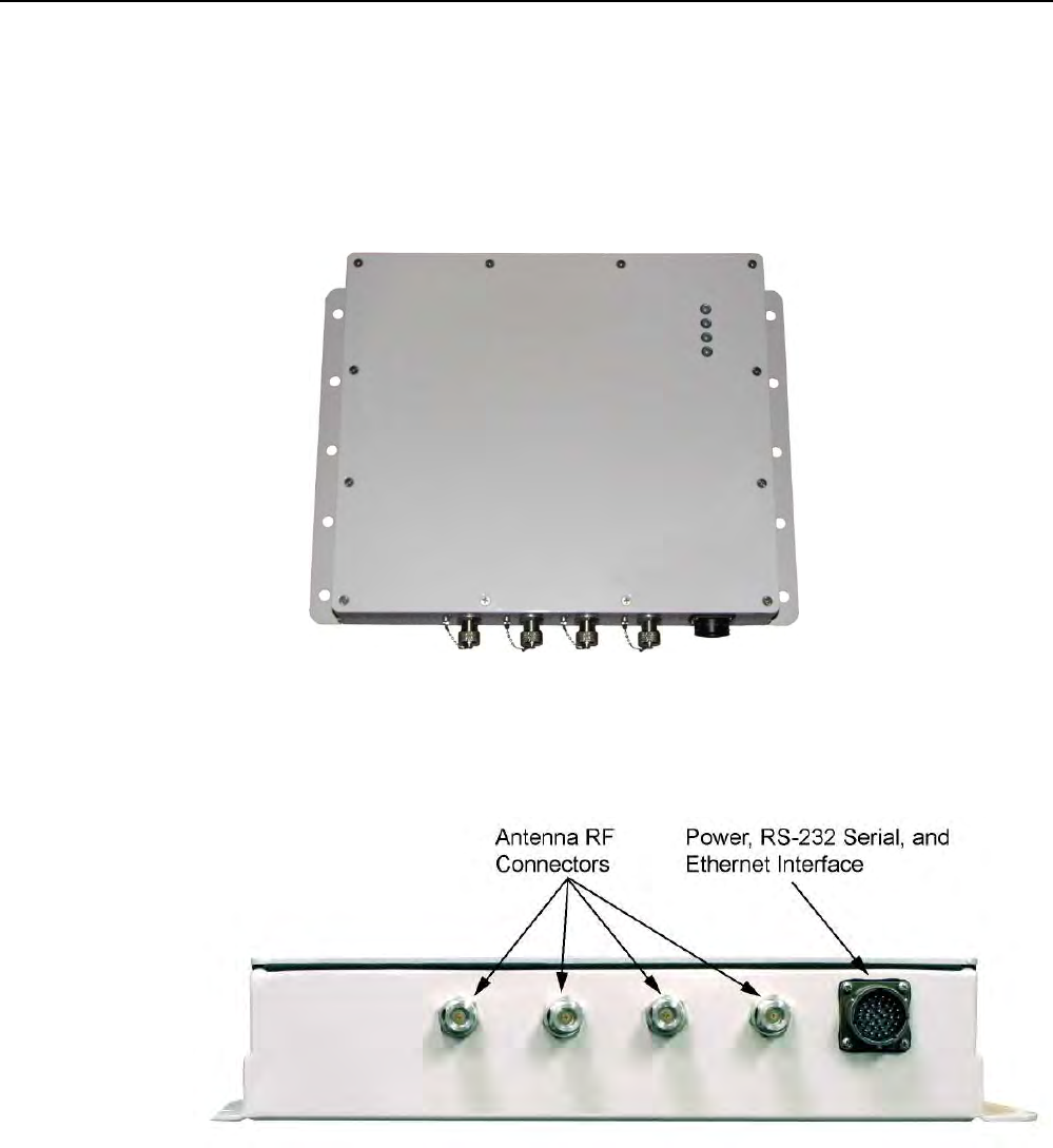
The 3M Toll RFID Reader 6204 is a multi-protocol, multi-regional Radio
Frequency Identification (RFID) System that operates in the 860–960 MHz
UHF band. The reader is configured at the factory to operate within a
specific regulatory region (for example: FCC Part 90).
Figure 1 3M Toll RFID Reader 6204
As shown in the following figure, the 6204 supports four Tx/Rx antennas
(not shown). The reader is also equipped with RS-232 serial and Ethernet
interfaces.
Figure 2 3M Toll RFID Reader 6204 Power and I/O Connections
1
11
1
2 3
4
5
6
7
8
9
Reader Overview
Reader OverviewReader Overview
Reader Overview
2
22
2
3M Toll RFID Reader 6204
3M Toll RFID Reader 62043M Toll RFID Reader 6204
3M Toll RFID Reader 6204
User’s Guide
User’s GuideUser’s Guide
User’s Guide
1.2. Reader Software
Reader SoftwareReader Software
Reader Software
The 6204 is shipped with two software applications that you can use to
configure and control the reader.
Reader Startup Tool (RST
Reader Startup Tool (RSTReader Startup Tool (RST
Reader Startup Tool (RST)
))
)
The RST is a Microsoft Windows based application you install on your
computer. With RST, you can view all readers on your network. After
selecting a reader, you can modify its communication, network, and
operational parameters. You can also read tags, review tag data, and
perform diagnostics. This RST is primarily intended for initially configuring a
reader prior to deployment. After deployment, use the Embedded Reader
Configuration Tool (RCT). Detailed information on the RST is provided in
Chapter 5.
Embedded
Embedded Embedded
Embedded Reader Configuration Tool (RCT)
Reader Configuration Tool (RCT)Reader Configuration Tool (RCT)
Reader Configuration Tool (RCT)
This RCT is an embedded reader application that allows you to access your
readers across a LAN or WAN. Enter the IP address of the reader into your
Web browser and the RCT allows you to fully modify and operate the reader.
With the same functionality as the RST, this application allows you to modify
the reader’s communication, network, and operational parameters. You can
also read tags, review tag data, perform diagnostics, and upload new
software. This application is primarily intended for configuring and
managing deployed readers. Detailed information on the RCT is provided in
Chapter 6.
1
2
22
2
3
4
5
6
7
8
9
Reader Equipment Installation
Reader Equipment InstallationReader Equipment Installation
Reader Equipment Installation
3M Toll RFID Reader 6204
3M Toll RFID Reader 62043M Toll RFID Reader 6204
3M Toll RFID Reader 6204
User’s Guide
User’s GuideUser’s Guide
User’s Guide
3
33
3
2 Safety Information
Please read, understand, and follow all safety information contained in
these instructions prior to the use of this RFID Interrogator/Reader product.
Retain these instructions for future reference.
2.1. Intended Use
Intended UseIntended Use
Intended Use
This RFID Interrogator/Reader product is intended for use with RFID
antennas and transponders in vehicle related applications such as
Automatic Vehicle Identification (AVI), Intelligent Transportation Systems
(ITS), Traffic Management Systems (TMS), Electronic Vehicle Registration
(EVR) and/or parking and access control. It is expected that all users be
fully trained in the safe operation of this device. Use in any other application
has not been evaluated by 3M and may lead to an unsafe condition.
2.2. Explanation of Signal Word Consequences
Explanation of Signal Word ConsequencesExplanation of Signal Word Consequences
Explanation of Signal Word Consequences
WARNING
WARNINGWARNING
WARNING: Indicates a hazardous situation which, if not avoided, could result in
death or serious injury
CAUTION
CAUTIONCAUTION
CAUTION: Indicates a hazardous situation which, if not avoided, could result in
minor or moderate injury or property damage.
NOTICE:
NOTICE:NOTICE:
NOTICE: Indicates a situation which, if not avoided, could result in property
damage.
2.3. Attendant Warnings
Attendant WarningsAttendant Warnings
Attendant Warnings
WARNING
WARNINGWARNING
WARNING: To reduce the risks associated with hazardous voltage, and non-
ionizing radiation exposure:
• Do not modify or attempt to service the Reader System. Return to 3M authorized
service centers for repair or service. There are no user serviceable parts.
WARNING
WARNINGWARNING
WARNING: To reduce the risks associated with exposure to non-ionizing radiation
exposure:
• Do not modify software outside the parameters stated in the manual.

1
2
22
2
3
4
5
6
7
8
9
Reader Equipment Installation
4
44
4
3M Toll RFID Reader 6204
3M Toll RFID Reader 62043M Toll RFID Reader 6204
3M Toll RFID Reader 6204
User’s Guide
User’s GuideUser’s Guide
User’s Guide
2.4. Installation and Service Technician Warnings and
Installation and Service Technician Warnings and Installation and Service Technician Warnings and
Installation and Service Technician Warnings and
Cautions
CautionsCautions
Cautions
WARNING
WARNINGWARNING
WARNING: To reduce the risks associated with hazardous voltage, fire and impact:
• Installation and service of 3M Toll RFID Reader systems is to be performed by
qualified installation personnel.
• Installation and service activities must be in compliance with all applicable
building and electrical codes.
• Inspect all system components at least every 6 months.
2.4.1. Power Supply Related
Power Supply RelatedPower Supply Related
Power Supply Related
WARNING
WARNINGWARNING
WARNING: To reduce the risks associated with hazardous voltage and fire:
• Always disconnect the power supply system power before any installation,
maintenance, service or modification work.
• Ensure that it cannot be re-connected inadvertently.
• Connection to main power supply in compliance with VDE01000 and EN50178.
• With Stranded wires: all strands must be secured in the terminal blocks.
• Power supply and cables must be properly fused.
• If necessary, a manually controlled disconnecting element must be used to
disengage from supply mains.
• All output lines must be rated for the power supply output current and must be
connected with the correct polarity.
• Do not block vents on power supply.
• For use in only a Pollution Degree 2 environment.
• Do not introduce any object into the power supply.
• Keep power supply away from fire and water.

1
2
22
2
3
4
5
6
7
8
9
Reader Equipment Installation
Reader Equipment InstallationReader Equipment Installation
Reader Equipment Installation
3M Toll RFID Reader 6204
3M Toll RFID Reader 62043M Toll RFID Reader 6204
3M Toll RFID Reader 6204
User’s Guide
User’s GuideUser’s Guide
User’s Guide
5
55
5
2.4.2. Reader System
Reader SystemReader System
Reader System
Related
RelatedRelated
Related
WARNING:
WARNING:WARNING:
WARNING: To reduce the risks associated with hazardous voltage and fire:
• Always disconnect AC power from the power supply unit when connecting or
disconnecting components of the system.
• System modification and service by 3M authorized personnel only.
WARNING:
WARNING:WARNING:
WARNING: To reduce the risks associated with hazardous voltage, and non-
ionizing radiation exposure:
• Do not modify or attempt to service the Reader System. Return to 3M authorized
service centers for repair or service. There are no user serviceable parts.
WARNING
WARNINGWARNING
WARNING: To reduce the risks associated with non-ionizing radiation exposure
and property damage:
• Always turn off the RF from the antenna before cleaning, inspecting, service or
repair.
WARNING
WARNINGWARNING
WARNING: To reduce the risks associated with electromagnetic interference:
• Use only the antennas described in this manual or the 3M RFID Antennas for Toll
RFID Readers Application Guide.

1
2
22
2
3
4
5
6
7
8
9
Reader Equipment Installation
6
66
6
3M Toll RFID Reader 6204
3M Toll RFID Reader 62043M Toll RFID Reader 6204
3M Toll RFID Reader 6204
User’s Guide
User’s GuideUser’s Guide
User’s Guide
WARNING
WARNINGWARNING
WARNING: To reduce the risks associated with hazardous temperature and fire
related to the power supply:
• Do not cover ventilation holes in power supply.
• Leave sufficient space around the power supply for cooling.
• Do not mount directly above a heat source.
• Disconnect unit from power before installation, maintenance, service, or
modification.
• Do not use in wet or damp locations.
• Do not use near flames.
• -Always disconnect AC power from the power supply unit when connecting or
disconnecting components of the system.
WARNING
WARNINGWARNING
WARNING: To reduce the risks associated with hazardous voltage:
• Replace damaged components with only the 3M designated replacement parts.
• Use only the power supply specified by 3M
WARNING
WARNINGWARNING
WARNING: To reduce the risks associated with fire and explosion:
• Do not install in a hazardous location.
WARNING
WARNINGWARNING
WARNING: To reduce the risks associated with impact:
• Any mounting surface must be able to support a minimum static load of equal to
the maximum weight of the reader plus any additional live load due to
environmental conditions.
WARNING
WARNINGWARNING
WARNING: To reduce the risks associated with impact, muscle strain and
abrasions:
• Use appropriate PPE and follow safe workplace practices during installation.
CAUTION
CAUTIONCAUTION
CAUTION: To reduce the risks associated with hot surfaces and reader
performance:
• Do not paint the reader, antenna(s), and power supply any color.
CAUTION
CAUTIONCAUTION
CAUTION: To reduce the risk associated with rough edges:
• Wear appropriate gloves when handling the reader and antenna mounting
hardware.
CAUTION
CAUTIONCAUTION
CAUTION: To reduce the risks associated with environmental contamination:
• Dispose of all system components in accordance with applicable local and
government regulations, including removal of button battery, prior to disposal.

1
2
22
2
3
4
5
6
7
8
9
Reader Equipment Installation
Reader Equipment InstallationReader Equipment Installation
Reader Equipment Installation
3M Toll RFID Reader 6204
3M Toll RFID Reader 62043M Toll RFID Reader 6204
3M Toll RFID Reader 6204
User’s Guide
User’s GuideUser’s Guide
User’s Guide
7
77
7
NOTICE:
NOTICE:NOTICE:
NOTICE:
Do not use 6204 with wire harness from previous reader installations. Power
pins have been moved.
Do not use solvents or harsh cleaners on radome or antennas.
2.5. RF Safety
RF SafetyRF Safety
RF Safety
NOTICE:
NOTICE:NOTICE:
NOTICE:
The 3M Toll RFID Reader 6204 UHF Reader is equipped with four (4) RF ports.
To prevent reader damage, unused RF ports must be properly terminated with
a 50 ohm load or a functional UHF antenna before power up if the reader has
been configured to use this port. Never power up the reader unless the
appropriate loads or antennas are connected. Always power down the reader
before removing an antenna or load from an RF port.
The maximum antenna cable length is 10 meters.
2.6. Electrostatic Discharge
Electrostatic DischargeElectrostatic Discharge
Electrostatic Discharge
ATTENTION
ATTENTIONATTENTION
ATTENTION
3M Toll RFID Reader
6204
antenna ports may be susceptible to
damage from static discharge or other high voltage. Use proper
Electrostatic Discharge (ESD) precautions to avoid static discharge
when handling or making connections to the 3M Toll RFID Reader
6204 reader antenna or communication ports. Equipment failure
can result if the antenna or communication ports are subjected to
ESD.

1
2
22
2
3
4
5
6
7
8
9
Reader Equipment Installation
8
88
8
3M Toll RFID Reader 6204
3M Toll RFID Reader 62043M Toll RFID Reader 6204
3M Toll RFID Reader 6204
User’s Guide
User’s GuideUser’s Guide
User’s Guide
2.7. Regulatory Compliance
Regulatory ComplianceRegulatory Compliance
Regulatory Compliance
NOTICE:
NOTICE:NOTICE:
NOTICE:
The 3M Toll RFID Reader 6204 is designed to meet the regulatory requirements in
those jurisdictions in which it is offered. Changes or modifications not expressly
approved by 3M for compliance could void the user's authority to operate the
equipment.
2.7.1. FCC Notice (3M Toll RFID Reader
FCC Notice (3M Toll RFID Reader FCC Notice (3M Toll RFID Reader
FCC Notice (3M Toll RFID Reader 6204
62046204
6204)
))
)
This equipment has been tested and found to comply with the limits for a Class A
digital device, pursuant to Part 15 of the FCC Rules. These limits are designed to
provide reasonable protection against harmful interference when the equipment is
operated in a commercial environment. This equipment generates, uses, and can
radiate radio frequency energy and, if not installed and used in accordance with the
instruction manual, may cause harmful interference to radio communications.
Operation of this equipment in a residential area is likely to cause harmful
interference in which case the user will be required to correct the interference at his
own expense.
2.7.2. FCC Notice (Wiegand Interface Module)
FCC Notice (Wiegand Interface Module)FCC Notice (Wiegand Interface Module)
FCC Notice (Wiegand Interface Module)
The Wiegand Interface Module has been tested and found to comply with the limits
for a Class B digital device, pursuant to Part 15 of the FCC Rules. These limits are
designed to provide reasonable protection against harmful interference in a
residential installation. This equipment generates, uses, and can radiate radio
frequency energy and, if not installed and used in accordance with the instructions,
may cause harmful interference to radio communications. However, there is no
guarantee that interference will not occur in a particular installation. If this
equipment does cause harmful interference to radio or television reception, which
can be determined by turning the equipment off and on, the user is encouraged to
try to correct the interference by one or more of the following measures:
• Reorient or relocate the receiving antenna.
• Increase the separation between the equipment and receiver.
• Connect the equipment into an outlet on a circuit different from that to which the
receiver is connected.
• Consult the dealer or an experienced radio/TV technician for help.
2.8. Power/
Power/Power/
Power/Data Cable Size
Data Cable SizeData Cable Size
Data Cable Size
NOTICE:
NOTICE:NOTICE:
NOTICE:
The 3M supplied power/data cable is only to be used with the 3M 24 VDC power
supply. Use of these cables with power supplies providing lesser voltages may result in
cable and/or reader damage.
1
2
3
33
3
4
5
6
7
8
9
Reader Equipment Installation
Reader Equipment InstallationReader Equipment Installation
Reader Equipment Installation
3M Toll RFID Reader 6204
3M Toll RFID Reader 62043M Toll RFID Reader 6204
3M Toll RFID Reader 6204
User’s Guide
User’s GuideUser’s Guide
User’s Guide
9
99
9
3 Reader Equipment Installation
3.1. Mechanical Installation
Mechanical InstallationMechanical Installation
Mechanical Installation
The 3M Toll RFID Reader 6204 is available with two mounting flanges
suitable for most pole and wall mount applications. Any mounting surface
must be able to support a minimum static load of 11.0 pounds (5 kg) plus
any additional live load due to environmental conditions.
Figure 3 3M Toll RFID Reader 6204 Mechanical Dimensions and Mounting Hole Locations (Dimensions in Inches)
1
2
3
33
3
4
5
6
7
8
9
Reader Equipment Installation
Reader Equipment InstallationReader Equipment Installation
Reader Equipment Installation
10
1010
10
3M Toll RFID Reader 6204
3M Toll RFID Reader 62043M Toll RFID Reader 6204
3M Toll RFID Reader 6204
User’s Guide
User’s GuideUser’s Guide
User’s Guide
To mount the 6204 assembly, refer to Figure 3 and perform the following:
1
11
1 Prepare the mounting surface to accept the 10 mounting bolts. The
hole pattern should match that shown in Figure 3 and the mounting
surface must be able to support 11 lbs (5 kg).
2
22
2 Mount the reader.
3
33
3 Locate the Interface Cable.
4
44
4 Connect the cable to the reader’s bulk head connector and twist to lock
in place.
5
55
5 Connect the antenna cables (see Figure 4).
6
66
6 Adjust the angle of the antennas and tighten the hardware.
1
2
3
33
3
4
5
6
7
8
9
Reader Equipment Installation
Reader Equipment InstallationReader Equipment Installation
Reader Equipment Installation
3M Toll RFID Reader 6204
3M Toll RFID Reader 62043M Toll RFID Reader 6204
3M Toll RFID Reader 6204
User’s Guide
User’s GuideUser’s Guide
User’s Guide
11
1111
11
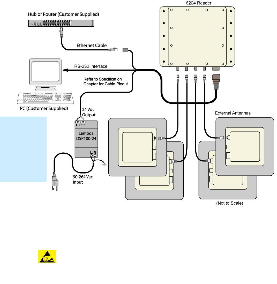
3.2. Electrical Installation
Electrical InstallationElectrical Installation
Electrical Installation
A general installation diagram is shown in the following figure. Refer to
Chapter 7 – Specifications for specific information.
Figure 4 3M Toll RFID Reader 6204 Electrical Connections
NOTICE
NOTICENOTICE
NOTICE:
::
:
The 3M Toll RFID Reader 6204 is designed to meet the regulatory requirements in those
jurisdictions in which it is offered. Changes or modifications not expressly approved by 3M
for compliance could void the user's authority to operate the equipment.
ATTENTION
ATTENTIONATTENTION
ATTENTION
3M Toll RFID Reader 6204 antenna ports may be susceptible to damage
from static discharge or other high voltage. Use proper Electrostatic
Discharge (ESD) precautions to avoid static discharge when handling or
making connections to the 3M Toll RFID Reader 6204 reader antenna or
communication ports. Equipment failure can result if the antenna or
communication ports are subjected to ESD.
Installation
Installation Installation
Installation
Notice
NoticeNotice
Notice
Installation of the
3M Toll RFID
Reader 6204 is
only to be
performed by
trained, 3M
approved
personnel.
1
2
3
33
3
4
5
6
7
8
9
Reader Equipment Installation
Reader Equipment InstallationReader Equipment Installation
Reader Equipment Installation
12
1212
12
3M Toll RFID Reader 6204
3M Toll RFID Reader 62043M Toll RFID Reader 6204
3M Toll RFID Reader 6204
User’s Guide
User’s GuideUser’s Guide
User’s Guide
3.2.1. Connecting the Serial Port
Connecting the Serial PortConnecting the Serial Port
Connecting the Serial Port
The 6204 RS-232 serial port provides communication up to 115200 Baud.
This port is accessed through the bulkhead connector on the reader. If you
are using the serial port for reader communication, connect a serial cable
from the COM port on your PC to the serial port on the reader. See Figure 2
for location of the connector.
Refer to the Chapter 8 – Specifications for details on the bulkhead
connector.
3.2.2. Connecting and Configuring the Ethernet Port
Connecting and Configuring the Ethernet PortConnecting and Configuring the Ethernet Port
Connecting and Configuring the Ethernet Port
The 6204 Ethernet port is accessed through the bulkhead connector. If you
are communicating with your reader across a Local Area Network (LAN),
connect an Ethernet cable from your hub or router to the bulkhead
connector.
By default, the reader is configured to use a DHCP server to obtain its IP
address and related information. In the event a DHCP server is unavailable,
the reader will boot with an IP address in the 169.254.x.x subnet.
In the absence of other readers on the same network, and if no other
network traffic is observed which references 169.254.1.1, the reader will
select that address; otherwise, it will select a random address on the
169.254.x.x subnet.
IP address settings can be changed using RST. Refer to the View or Change
the Reader’s Network Settings section in Chapter 5.
Refer to the Chapter 8 – Specifications for details on the bulkhead
connector.
3.2.3. Connecting Digital Inputs/Outputs
Connecting Digital Inputs/OutputsConnecting Digital Inputs/Outputs
Connecting Digital Inputs/Outputs
The 6204 is equipped with a general purpose digital input/output (I/O) port
that provides four optically isolated 5-24 VDC input signals and four open-
collector output signals. The digital inputs can be used as general purpose
inputs or to trigger the reader for tag reading. These inputs can be
configured to provide an external read trigger from proximity sensors, photo
switches, or other devices.
The digital outputs can be used as general purpose outputs, to indicate tag
reading activity, or to indicate the reader is transmitting (RF On). The
outputs can also be configured to trigger conveyor gates or other access
control and sorting devices. For detailed information on configuring the
digital inputs and outputs refer to Chapter 7.
1
2
3
33
3
4
5
6
7
8
9
Reader Equipment Installation
Reader Equipment InstallationReader Equipment Installation
Reader Equipment Installation
3M Toll RFID Reader 6204
3M Toll RFID Reader 62043M Toll RFID Reader 6204
3M Toll RFID Reader 6204
User’s Guide
User’s GuideUser’s Guide
User’s Guide
13
1313
13
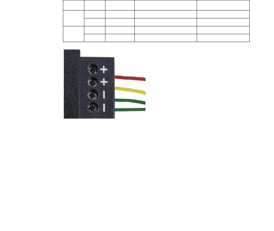
3.2.4. Connecting the Power
Connecting the PowerConnecting the Power
Connecting the Power
The 6204 operates on 24 Vdc ±5% provided through the bulkhead
connector on the rear of the reader.
The bulkhead power connections are as follows. Note that both pairs must
be connected.
Pair
PairPair
Pair
Pin
PinPin
Pin
Color
ColorColor
Color
Pin Name
Pin NamePin Name
Pin Name
Function
FunctionFunction
Function
9 T Red +24 VDC Power
U Green 24 VDC GND Ground
16 h Yellow +24 VDC Heater Power
j Green 24 VDC GND Heater Ground
Connect the power supply to the reader cable as shown and connect the
power supply to your 100–240 Vac, 50-60 Hz power source. Allow 30
seconds for the reader to initialize.
NOTICE
NOTICENOTICE
NOTICE:
::
:
If DC power is disconnected from the reader, wait a minimum of 30 seconds before
reapplying power.
Refer to the Chapter 8 – Specifications for additional details on the
bulkhead connector.
NOTICE
NOTICENOTICE
NOTICE:
::
:
The 3M supplied power cable is only rated at 24V ±5%. Input power less than 24V ±5% while
using 3M supplied cables may result in cable and/or reader damage.
3.2.5. Installation with the 3M Reader Redundancy Switch
Installation with the 3M Reader Redundancy SwitchInstallation with the 3M Reader Redundancy Switch
Installation with the 3M Reader Redundancy Switch
The 6204 can be installed with the optional 3M Reader Redundancy Switch
(RRS). The RRS interfaces two 3M Toll RFID Reade 6204s and their
associated antenna systems to provide an antenna change over facility in
the event of a reader failure. Please consult the 3M Reader Redundancy
Switch User’s Guide for installation details.
1
2
3 4
44
4
5
6
7
8
9
RST Software Installation
RST Software InstallationRST Software Installation
RST Software Installation
14
1414
14
3M Toll RFID Reader 6204
3M Toll RFID Reader 62043M Toll RFID Reader 6204
3M Toll RFID Reader 6204
User’s Guide
User’s GuideUser’s Guide
User’s Guide
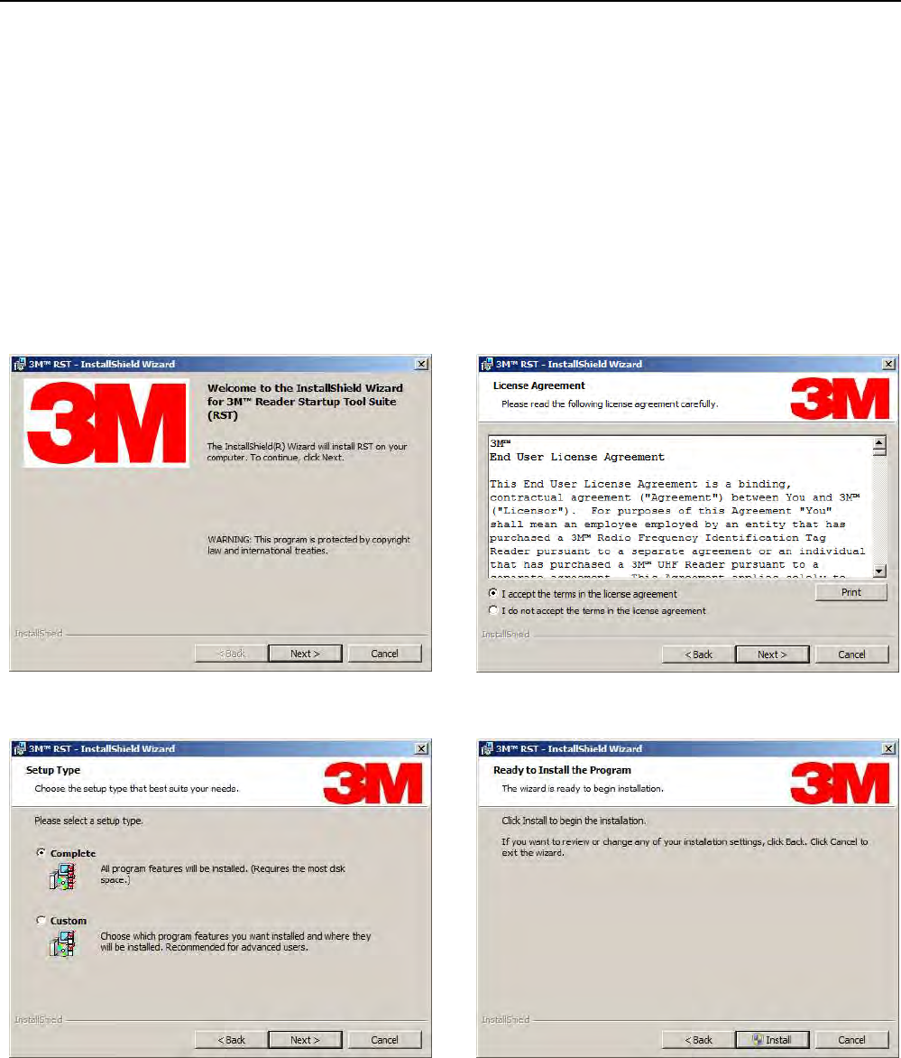
4 Reader Startup Tool (RST) Software Installation
4.1. Installing R
Installing RInstalling R
Installing RST
STST
ST
Software
SoftwareSoftware
Software
The 3M Toll RFID Reader 6204 is delivered with a Microsoft Windows
application called Reader Startup Tool (RST). You can use this application to
initially configure your reader as well as read and display tag data.
NOTE: The product CD provided with your reader contains a setup file called setup.exe.
This file will fully check your system configuration and load all required software
including Microsoft .Net 4.5.
Install RST
Install RSTInstall RST
Install RST
1
11
1 To install RST, load your product CD and double-click the setup.msi file:
2
22
2 Press Next> 3
33
3 Read the License Agreement. Select
I accept the terms… and press Next>
1
2
3 4
44
4
5
6
7
8
9
RST Software Installation
RST Software InstallationRST Software Installation
RST Software Installation
3M Toll RFID Reader 6204
3M Toll RFID Reader 62043M Toll RFID Reader 6204
3M Toll RFID Reader 6204
User’s Guide
User’s GuideUser’s Guide
User’s Guide
15
1515
15
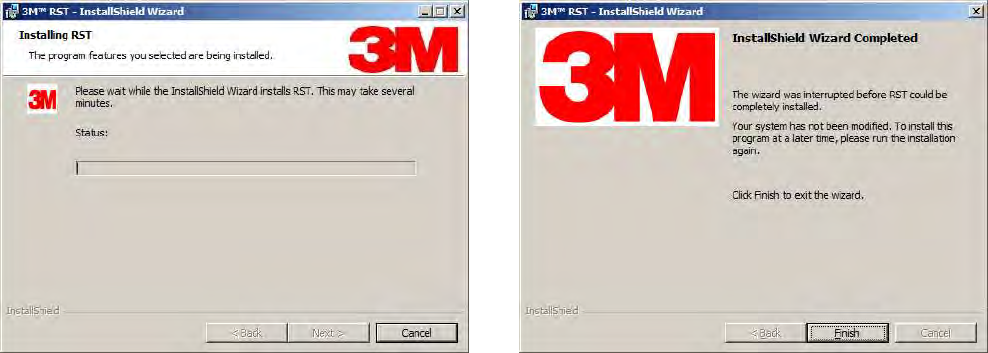
4
44
4 Select Setup Type. Press Next>. 5
55
5 Press Install.
5
55
5 Monitor the progress of the installation.
6
66
6 After the installation completes, press Finish.
1
2
3 4
44
4
5
6
7
8
9
RST Software Installation
RST Software InstallationRST Software Installation
RST Software Installation
16
1616
16
3M Toll RFID Reader 6204
3M Toll RFID Reader 62043M Toll RFID Reader 6204
3M Toll RFID Reader 6204
User’s Guide
User’s GuideUser’s Guide
User’s Guide
4.2. Windows 7 Setup
Windows 7 SetupWindows 7 Setup
Windows 7 Setup
If you have a Windows 7 operating system, your firewall may block UDP
traffic and consequently RST may not discover your readers. Perform the
following to configure your system:
For Microsoft Firewall
For Microsoft FirewallFor Microsoft Firewall
For Microsoft Firewall
1
11
1 Log into your computer as Administrator.
2
22
2 Navigate to the Control Panel and select
Control Panel → System and Security.
3
33
3 Select Allow a program through Windows firewall.
4
44
4 Scroll down the list and locate Startup Tool, check it, and press OK.
5
55
5 If Startup Tool is not in the list, press Allow another program.
6
66
6 Locate Startup Tool, check it, and press OK.
7
77
7 Restart RST and it should discover readers.
For Third
For ThirdFor Third
For Third-
--
-Party Firewalls
Party FirewallsParty Firewalls
Party Firewalls
1
11
1 Log into your computer as Administrator.
2
22
2 Set your firewall to allow RST to receive UDP traffic on port 50000 and
50001.
1
2
3 4
44
4
5
6
7
8
9
RST Software Installation
RST Software InstallationRST Software Installation
RST Software Installation
3M Toll RFID Reader 6204
3M Toll RFID Reader 62043M Toll RFID Reader 6204
3M Toll RFID Reader 6204
User’s Guide
User’s GuideUser’s Guide
User’s Guide
17
1717
17
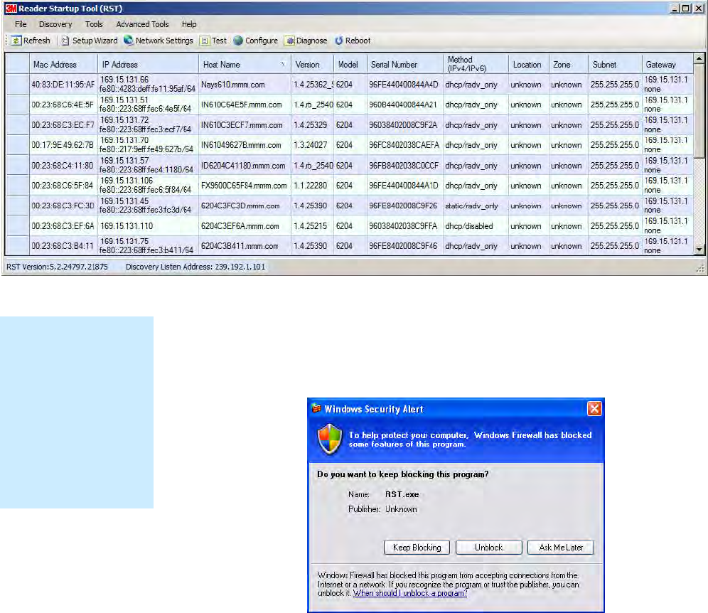
4.3. Reader Startup
Reader StartupReader Startup
Reader Startup
To begin using your reader, open the RST application.
Open RST
Open RSTOpen RST
Open RST
1
11
1 From your Windows desktop, select:
Start→Programs→3M→Reader Startup Tool (RST)
2
22
2 If this is the first time starting the RST application, you may receive a
Windows Security Alert. This warning indicates that the firewall is
blocking the RST application.
3
33
3 If the warning window is hidden under the RST windows, collapse the
RST window.
4
44
4 Press Unblock.
5
55
5 Press Refresh on the RST
6
66
6 The RST main page will display any readers currently connected to the
network.
NOTE:
NOTE:NOTE:
NOTE:
Earlier versions of
Microsoft Windows™
may not provide the
Security Alert popup.
IF RST does not
discover your reader,
check your Windows
Firewall/Security
settings.
1
2
3 4
44
4
5
6
7
8
9
RST Software Installation
RST Software InstallationRST Software Installation
RST Software Installation
18
1818
18
3M Toll RFID Reader 6204
3M Toll RFID Reader 62043M Toll RFID Reader 6204
3M Toll RFID Reader 6204
User’s Guide
User’s GuideUser’s Guide
User’s Guide
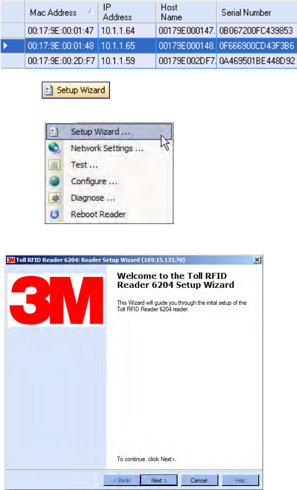
4.4. Initial Reader Setup
Initial Reader SetupInitial Reader Setup
Initial Reader Setup
To configure a specific reader, perform the following:
Reader Setup
Reader SetupReader Setup
Reader Setup
1
11
1 Select the reader on the main RST page by clicking the button to the left
of the reader Mac address.
2
22
2 Press the button on the RST tool bar or select Setup
Wizard from the Tools pull-down menu.
3
33
3 The Reader Setup Wizard (RSW) is displayed.
1
2
3 4
44
4
5
6
7
8
9
RST Software Installation
RST Software InstallationRST Software Installation
RST Software Installation
3M Toll RFID Reader 6204
3M Toll RFID Reader 62043M Toll RFID Reader 6204
3M Toll RFID Reader 6204
User’s Guide
User’s GuideUser’s Guide
User’s Guide
19
1919
19
4
44
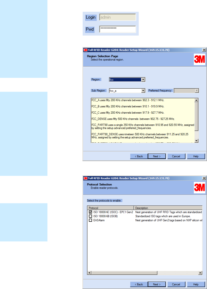
4 Press Next> and enter the Login (admin) and Password. If this is the
first time configuring your reader, enter: readeradmin.
5
55
5 After entering your Login and Password, press Next>
6
66
6 Select the Region and Sub Region and press Next>.
Protocols
ProtocolsProtocols
Protocols
Only those protocols
enabled in the reader
will be active on the
Protocol Selection
page.
Region Selection
Region SelectionRegion Selection
Region Selection
The reader is
configured at the
factory to operate
within a specific
regulatory region. As
a result your region
selections may be
different from those
shown in this
manual.
Note that Region
Selection is not user
configurable.
Login Page
Login PageLogin Page
Login Page
The reader Login
Page is only
displayed when the
default login is set to
guest. Readers
leave the factory with
a default login of
admin. Therefore,
you will not see the
login screen if you
have not configured
your reader.
1
2
3 4
44
4
5
6
7
8
9
RST Software Installation
RST Software InstallationRST Software Installation
RST Software Installation
20
2020
20
3M Toll RFID Reader 6204
3M Toll RFID Reader 62043M Toll RFID Reader 6204
3M Toll RFID Reader 6204
User’s Guide
User’s GuideUser’s Guide
User’s Guide
7
77
7 Select the protocol of the tags you will be reading and press Next>.
8
88
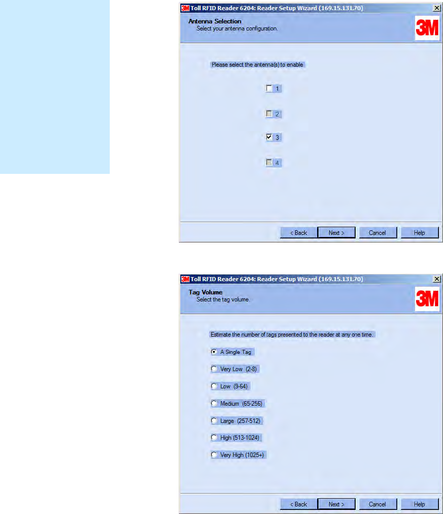
8 Select the antennas you will be installing and press Next>.
9
99
9 Estimate the number of tags that will be presented to the reader at any
one time and press Next>.
Custom Setup
Custom SetupCustom Setup
Custom Setup
If your installation
type differs from one
of the choices shown
in the Setup Wizard,
you can always
customize your setup
later using the
embedded web
interface capability.
See the Advanced
Setup chapter in this
guide for more
information.
1
2
3 4
44
4
5
6
7
8
9
RST Software Installation
RST Software InstallationRST Software Installation
RST Software Installation
3M Toll RFID Reader 6204
3M Toll RFID Reader 62043M Toll RFID Reader 6204
3M Toll RFID Reader 6204
User’s Guide
User’s GuideUser’s Guide
User’s Guide
21
2121
21
10
1010
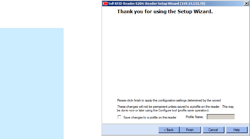
10 It is highly recommended that you save the reader setup as a profile.
Select Save changes to a profile…, enter a Profile Name, and press
Finish to complete the initial reader setup.
Saving Reader Setup
Saving Reader SetupSaving Reader Setup
Saving Reader Setup
Reader setup
information should be
saved as a profile. In
the event that you
need to reboot or
power down a reader,
the reader setup can
be quickly reloaded
by loading the profile.
If you don’t save the
reader setup, you can
lose the information if
the reader is
rebooted.
1
2
3
4 5
55
5
6
7
8
9
Reader Operation
Reader OperationReader Operation
Reader Operation
22
2222
22
3M Toll RFID Reader 6204
3M Toll RFID Reader 62043M Toll RFID Reader 6204
3M Toll RFID Reader 6204
User’s Guide
User’s GuideUser’s Guide
User’s Guide
5 Reader Operation
5.1. Basic Operation with
Basic Operation with Basic Operation with
Basic Operation with R
RR
RST
STST
ST
The 3M Toll RFID Reader 6204 can be operated either from the RST
application or by logging directly into the reader’s embedded Reader
Configuration Tool (RCT). To operate the reader from RST, perform the
following:
Open RST
Open RSTOpen RST
Open RST
1
11
1 From your Windows desktop, select:
Start→Programs→3M→Reader Startup Tool (RST)
2
22
2 Select a reader and press on the RST tool bar or select Test
from the Tools pull-down menu.
Customize the display
Customize the displayCustomize the display
Customize the display
Customize your RST
display by clicking
and dragging the
columns. You can
also sort by column.
1
2
3
4 5
55
5
6
7
8
9
Reader Operation
Reader OperationReader Operation
Reader Operation
3M Toll RFID Reader 6204
3M Toll RFID Reader 62043M Toll RFID Reader 6204
3M Toll RFID Reader 6204
User’s Guide
User’s GuideUser’s Guide
User’s Guide
23
2323
23
3
33
3 The Reader Test Tool (RTT) is displayed.
4
44
4 Login to the reader. From the pull-down menu select Reader→Login….
5
55
5 For administrator login, select admin. The initial password (Pwd) is
readeradmin. Refer to the 3M Toll RFID Reader 6204 P
3M Toll RFID Reader 6204 P3M Toll RFID Reader 6204 P
3M Toll RFID Reader 6204 Protocol
rotocol rotocol
rotocol
Reference Guide
Reference GuideReference Guide
Reference Guide
for instructions on how to use the reader.set_pwd
command to change the password.
6
66
6 Verify the Operating Mode is set to Active. From the pull-down menu
select Operating Mode→Active.
7
77
7 Select the Tag Performance tab and press Start.
8
88
8 Place tags in front of antenna and verify tags are read and displayed.
1
2
3
4 5
55
5
6
7
8
9
Reader Operation
Reader OperationReader Operation
Reader Operation
24
2424
24
3M Toll RFID Reader 6204
3M Toll RFID Reader 62043M Toll RFID Reader 6204
3M Toll RFID Reader 6204
User’s Guide
User’s GuideUser’s Guide
User’s Guide
5.2. Deployed Reader Operation
Deployed Reader OperationDeployed Reader Operation
Deployed Reader Operation
with RCT
with RCTwith RCT
with RCT
Once your readers are deployed, you can access them directly using the
embedded Reader Configuration Tool (RCT). To access a particular reader,
perform the following:
1
11
1 Enter the reader’s IP address into your web browser, press the
button on the RST tool bar or select Configure from the
Tools pull-down menu.
2
22
2 The reader’s RCT interface is displayed.
3
33
3 Log into the reader. Press Login for the login screen.
4
44
4 The default login is guest. If you need administrator privileges, login as
admin and enter readeradmin as the password.
5
55
5 Press Submit.
6
66
6 Select Basic Configuration →Setup Antenna/Cables to configure the
antennas, gain, and power settings.
1
2
3
4 5
55
5
6
7
8
9
Reader Operation
Reader OperationReader Operation
Reader Operation
3M Toll RFID Reader 6204
3M Toll RFID Reader 62043M Toll RFID Reader 6204
3M Toll RFID Reader 6204
User’s Guide
User’s GuideUser’s Guide
User’s Guide
25
2525
25
7
77
7 Select Advanced Functions →Change Operating Mode to verify the
reader is in the proper mode.
8
88
8 Select Basic Configuration →Set Tag Protocol to verify the reader is
configured for the proper tag protocol.
9
99
9 Press System Status →View Tags to view tag data.
10
1010
10 If you need to configure additional changes to your reader, refer to
Chapter 7 – Reader Configuration Tool for information on using RCT to
adjust configuration variables and parameters.
1
2
3
4
5
6
66
6
7
8
9
Reader Startup Tool
Reader Startup ToolReader Startup Tool
Reader Startup Tool
26
2626
26
3M Toll RFID Reader 6204
3M Toll RFID Reader 62043M Toll RFID Reader 6204
3M Toll RFID Reader 6204
User’s Guide
User’s GuideUser’s Guide
User’s Guide
6 Reader Startup Tool (RST)
The Reader Startup Tool (RST) provides an easy-to-use interface for the 3M
Toll RFID Reader 6204 configuration and operation functions. This
application resides on your Windows based computer and allows you to
perform the following:
View all readers on the network
Launch the Reader Setup Wizard to configure a reader
View and change a reader’s network settings
Add a new reader to the network
Launch Reader Test Tool to perform basic reader/tag operations
Launch Reader Diagnostic Tool to view statistics, alarms, and reports
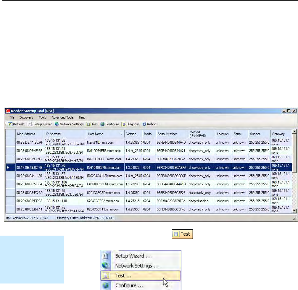
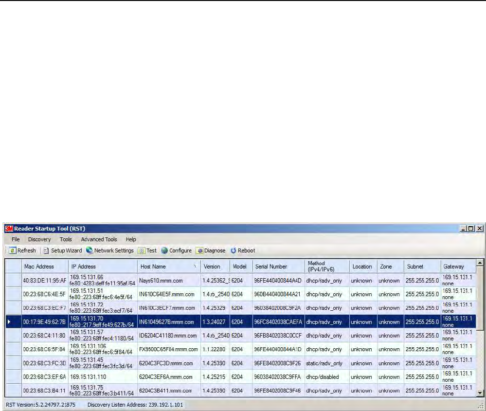
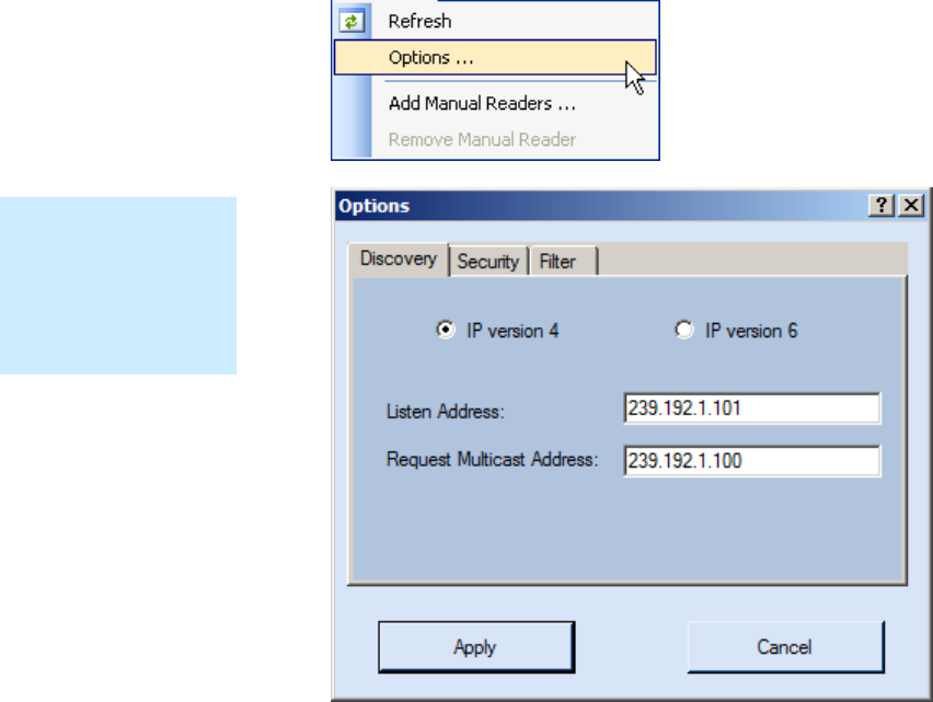
6.1. View Readers on the Network
View Readers on the NetworkView Readers on the Network
View Readers on the Network
When RST starts up, all readers currently connected to the network and
powered up are displayed.
1
2
3
4
5
6
66
6
7
8
9
Reader Startup Tool
Reader Startup ToolReader Startup Tool
Reader Startup Tool
3M Toll RFID Reader 6204
3M Toll RFID Reader 62043M Toll RFID Reader 6204
3M Toll RFID Reader 6204
User’s Guide
User’s GuideUser’s Guide
User’s Guide
27
2727
27
6.2. Configure
ConfigureConfigure
Configure
Reader
Reader Reader
Reader with the
with the with the
with the Setup Wizard
Setup WizardSetup Wizard
Setup Wizard
The Reader Setup Wizard is used to initially configure your reader for
operation. With this application, you can select the following:
Installation type
Regulatory region and sub-region
Protocol
Number of antennas
Estimated tag volume
To
ToTo
To
initially configure your reader perform the following:
initially configure your reader perform the following:initially configure your reader perform the following:
initially configure your reader perform the following:
1
11
1 Press the button on the RST tool bar or select Setup
Wizard from the Tools pull-down menu.
2
22
2 The Reader Setup Wizard (RSW) is displayed.
3
33
3 Refer to Chapter 2 – Reader Configuration for detailed instructions on
using the Reader Setup Wizard.
1
2
3
4
5
6
66
6
7
8
9
Reader Startup Tool
Reader Startup ToolReader Startup Tool
Reader Startup Tool
28
2828
28
3M Toll RFID Reader 6204
3M Toll RFID Reader 62043M Toll RFID Reader 6204
3M Toll RFID Reader 6204
User’s Guide
User’s GuideUser’s Guide
User’s Guide
6.3. Customize Discovery Options
Customize Discovery OptionsCustomize Discovery Options
Customize Discovery Options
You can customize the reader discovery options including the Listen
Address and Request Multicast Address.
Listen Address – Address that RST uses to listen for UDP discovery
packets from the reader. This is customizable on the reader.
Request Multicast Address –Address used by RST to send out the UDP
update request packets. This is customizable on the reader.
In addition, you can select if you want a secure connection for the Test,
Configure, and Diagnostic Tools. This connection uses the HTTPS protocol
and any data transferred between devices is encrypted.
1
11
1 On the RST tool bar select Options from the Discovery pull-down menu.
2
22
2 Select either IP version 4 or IP version 6.
3
33
3 Enter the Listen Address and Request Multicast Address as required.
4
44
4 Select whether you require a secure connection for the Test, Configure,
and Diagnostic Tools.
5
55
5 Press Apply.
Only Display Specific
Only Display Specific Only Display Specific
Only Display Specific
Reader Models
Reader ModelsReader Models
Reader Models
Select Options
OptionsOptions
Options→Filter
→Filter→Filter
→Filter
to view only specific
reader models.
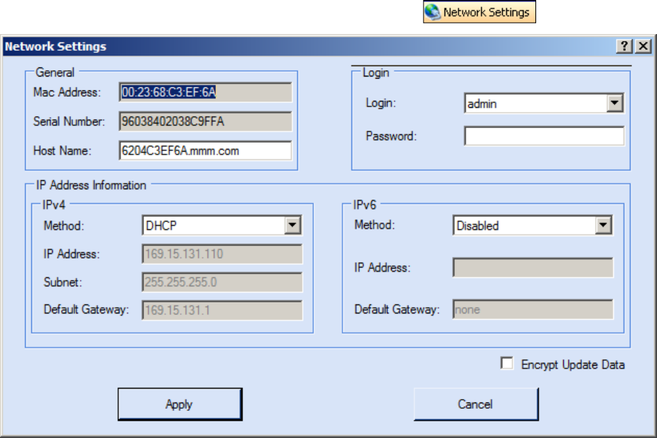
1
2
3
4
5
6
66
6
7
8
9
Reader Startup Tool
Reader Startup ToolReader Startup Tool
Reader Startup Tool
3M Toll RFID Reader 6204
3M Toll RFID Reader 62043M Toll RFID Reader 6204
3M Toll RFID Reader 6204
User’s Guide
User’s GuideUser’s Guide
User’s Guide
29
2929
29
6.4. View or Change the Reader’s Network Settings
View or Change the Reader’s Network SettingsView or Change the Reader’s Network Settings
View or Change the Reader’s Network Settings
1
11
1 From the RST main page, press the button.
2
22
2 Verify the IP Address, Subnet, and Default Gateway are correct.
3
33
3 If Method: DHCP is selected these fields will be locked.
4
44
4 If required, change the values.
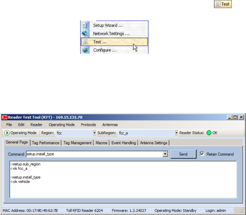
1
2
3
4
5
6
66
6
7
8
9
Reader Startup Tool
Reader Startup ToolReader Startup Tool
Reader Startup Tool
30
3030
30
3M Toll RFID Reader 6204
3M Toll RFID Reader 62043M Toll RFID Reader 6204
3M Toll RFID Reader 6204
User’s Guide
User’s GuideUser’s Guide
User’s Guide
6.5. Reader Test Tool (RTT)
Reader Test Tool (RTT)Reader Test Tool (RTT)
Reader Test Tool (RTT)
The Reader Test Tool (RTT) is primarily designed for new users to test
reader operation and perform a few basic reader functions. With RTT, you
can perform the following:
Read tags
Issue commands to the reader and view the responses
Run macros
Observe reader events
To access the Reader Test Tool, select a reader and press on
the RST tool bar or select Test from the Tools pull-down menu.
6.5.1. General Page
General PageGeneral Page
General Page
The General Page allows you to issue commands to the reader and view
any responses. From the pull-down menus, you can also login to the reader,
change the operating mode, select another protocol, and select which
antennas are active.
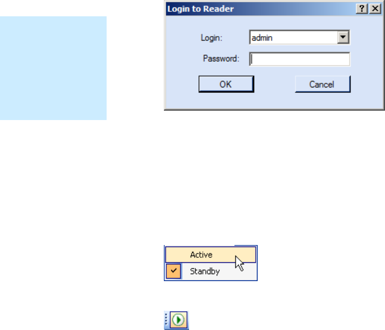
1
2
3
4
5
6
66
6
7
8
9
Reader Startup Tool
Reader Startup ToolReader Startup Tool
Reader Startup Tool
3M Toll RFID Reader 6204
3M Toll RFID Reader 62043M Toll RFID Reader 6204
3M Toll RFID Reader 6204
User’s Guide
User’s GuideUser’s Guide
User’s Guide
31
3131
31
Login to Reader
Login to ReaderLogin to Reader
Login to Reader
To login to the reader, perform the following:
1
11
1 From the pull-down menu, select Reader→Login….
2
22
2 Select the type of Login from the pull down. The default login is guest. If
you need administrator privileges, login as admin.
3
33
3 Enter your Password. Enter readeradmin as the password if you logged
in as admin.
4
44
4 Press OK.
Select Operating Mode
Select Operating ModeSelect Operating Mode
Select Operating Mode
From the pull-down menu, select Operating Mode→<Active | Standby>
or, press the Operating Mode select button on the left side of the tool bar.
Active – Reader is continuously attempting to singulate tags and
automatically reports any singulated tag via an asynchronous event
notification on the event channel.
Standby – Reader is not transmitting any RF energy, unless processing
a tag related command. The transmitter is enabled at the beginning of
the command processing, protocol operations required for the
command are performed, and then the RF transmitter is turned off.
Default Admin
Default Admin Default Admin
Default Admin
Password
PasswordPassword
Password
3M recommends
changing the default
Admin password once
installation,
configuration, and
testing are complete.
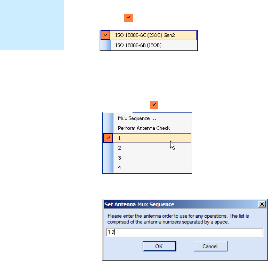
1
2
3
4
5
6
66
6
7
8
9
Reader Startup Tool
Reader Startup ToolReader Startup Tool
Reader Startup Tool
32
3232
32
3M Toll RFID Reader 6204
3M Toll RFID Reader 62043M Toll RFID Reader 6204
3M Toll RFID Reader 6204
User’s Guide
User’s GuideUser’s Guide
User’s Guide
Select Protocol
Select ProtocolSelect Protocol
Select Protocol
You can activate one or more protocols on the 6204 using RST. From the
pull-down menu, select Protocols→<protocol>
>>
>. Active protocols are
indicated by .
Antenna Selection
Antenna SelectionAntenna Selection
Antenna Selection
You can select the ports that have antennas connected and which antennas
are active. Perform the following:
1
11
1 From the pull-down menu, select Antennas→<n>. Active antennas
are indicated by .
2
22
2 You can also select the order in which antennas are activated. From the
pull-down menu, select Antennas→Mux sequence....
3
33
3 Enter the antenna numbers in the order to be activated.
4
44
4 Press OK.
NOTE
NOTENOTE
NOTE
Certain protocols
require licensing and
may not be available.
Contact 3M for more
information.
1
2
3
4
5
6
66
6
7
8
9
Reader Startup Tool
Reader Startup ToolReader Startup Tool
Reader Startup Tool
3M Toll RFID Reader 6204
3M Toll RFID Reader 62043M Toll RFID Reader 6204
3M Toll RFID Reader 6204
User’s Guide
User’s GuideUser’s Guide
User’s Guide
33
3333
33
Set Reader Options
Set Reader OptionsSet Reader Options
Set Reader Options
You can setup other reader options including help type macro highlighting.
From the pull-down menu, select Edit→Options.
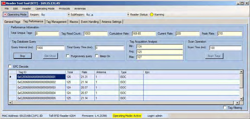
1
2
3
4
5
6
66
6
7
8
9
Reader Startup Tool
Reader Startup ToolReader Startup Tool
Reader Startup Tool
34
3434
34
3M Toll RFID Reader 6204
3M Toll RFID Reader 62043M Toll RFID Reader 6204
3M Toll RFID Reader 6204
User’s Guide
User’s GuideUser’s Guide
User’s Guide
6.5.2. Tag Performance Page
Tag Performance PageTag Performance Page
Tag Performance Page
The Tag Performance page is used to test the reader performance.
To initiate a timed test, enter the length of test (in ms) into the Total Query
Time field. For example, to verify to number of tags read in a 30-second
interval, select Active Operating Mode, enter 30000, and press the Start
button. The test will complete after 30 seconds and the output statistics are
updated for the query time.
Output statistics are read-only and include: Total Unique Tags, Tag Read
Count, Cumulative Rate, and Current Rate.
Detailed descriptions of the various Tag Performance fields and functions
are provided in the following sections.
Tag read controls are provided by the Tag Database Query and Scan
Operation blocks. Use the Query controls when the reader is in Active
mode. Use the Scan Operation controls when in Standby mode.
Tag and reader performance data is provided in the Performance
Information and Tag Acquisition Analysis blocks.
1
2
3
4
5
6
66
6
7
8
9
Reader Startup Tool
Reader Startup ToolReader Startup Tool
Reader Startup Tool
3M Toll RFID Reader 6204
3M Toll RFID Reader 62043M Toll RFID Reader 6204
3M Toll RFID Reader 6204
User’s Guide
User’s GuideUser’s Guide
User’s Guide
35
3535
35
Performance Information
Performance InformationPerformance Information
Performance Information
Total Unique Tags – Number of unique tags in the tag database.
Tag Read Count – Total number of tags read (including repeat reads).
Cumulative Rate – Cumulative read rate in tags/second since the Start
button was pressed.
Current Rate – Current read rate in tags/second.
Tag Database
Tag Database Tag Database
Tag Database Query
QueryQuery
Query
Controls
ControlsControls
Controls
Click to retrieve the current information from reader’s
tag database.
Click to query the tag database every Query Interval
(ms) for a total time of Total Query Time (ms). Do
not set the interval less than 500. If Total Query Time
is set to 0, query continues indefinitely.
Click to stop automatic query.
Indicates current read rate with audible tone.
Check to purge the reader’s tag database after each
query. Refer to the 3M Toll RFID Reader 6204
Protocol Reference Guide for more information on
the tag database.
Tag Acquisition Analysis
Tag Acquisition AnalysisTag Acquisition Analysis
Tag Acquisition Analysis
The Tag Acquisition Analysis fields provide the minimum, maximum, and
average number of times each tag was read. For example, assume five tags
(A, B, C, D, and E) are read 107, 59, 223, 187, and 94 times respectively.
The displayed values are as follows:
Min = 59
Avg = 134
Max = 223
Scan Operation
Scan OperationScan Operation
Scan Operation
Scan time (ms) – Enter the duration of reader operation in milliseconds.
After this time expires, the tag information is displayed.
Press this button to activate the reader.
Purge and Clear Reader Statistics
Purge and Clear Reader StatisticsPurge and Clear Reader Statistics
Purge and Clear Reader Statistics
Select the reader and then select Edit→Purge and Clear Statistics.
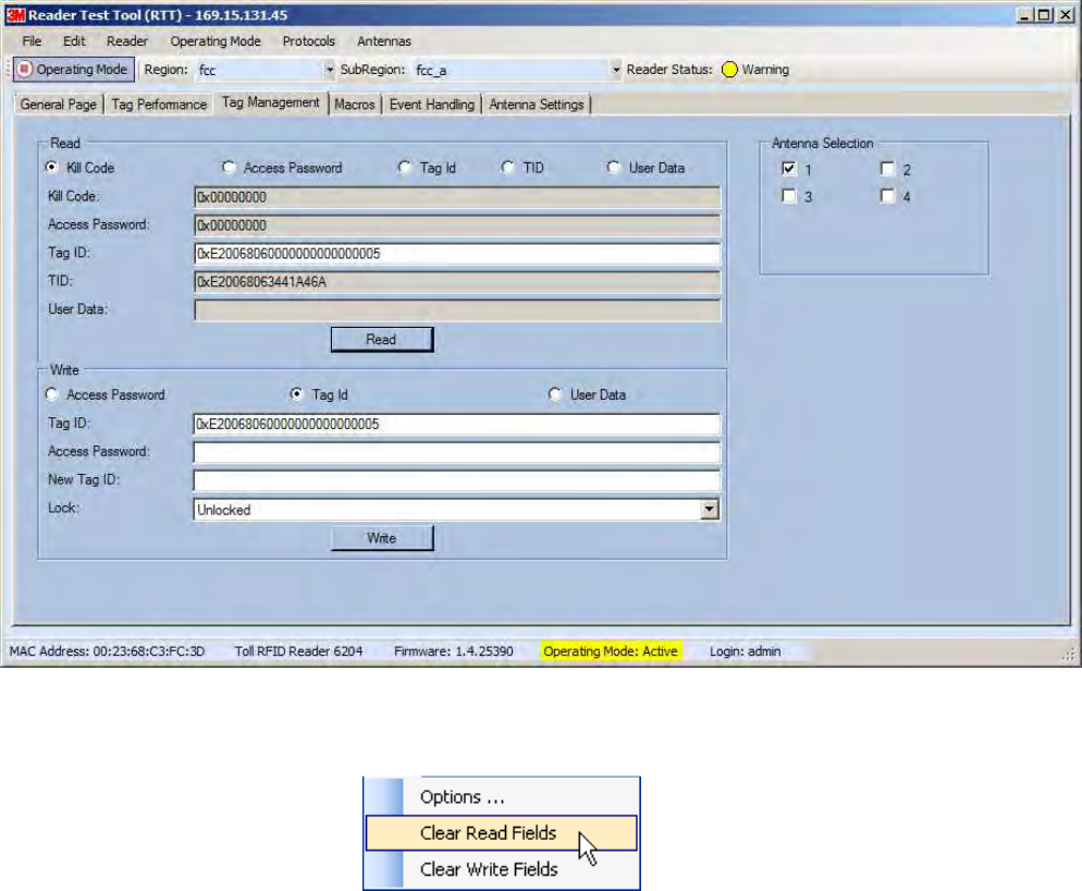
1
2
3
4
5
6
66
6
7
8
9
Reader Startup Tool
Reader Startup ToolReader Startup Tool
Reader Startup Tool
36
3636
36
3M Toll RFID Reader 6204
3M Toll RFID Reader 62043M Toll RFID Reader 6204
3M Toll RFID Reader 6204
User’s Guide
User’s GuideUser’s Guide
User’s Guide
6.5.3. Tag Management Page
Tag Management PageTag Management Page
Tag Management Page
The Tag Management page is used for reading individual fields on a single
tag as well as writing the access password and locking a tag. The Read
button will cause the reader to singulate and read a tag in the selected
antennas’ RF field. Specific fields you can read include:
Kill Code
Access Code
Tag ID
TID
User Data
Clear Read and Write Fields
Clear Read and Write FieldsClear Read and Write Fields
Clear Read and Write Fields
To clear the Read or Write fields, select Edit→Clear….
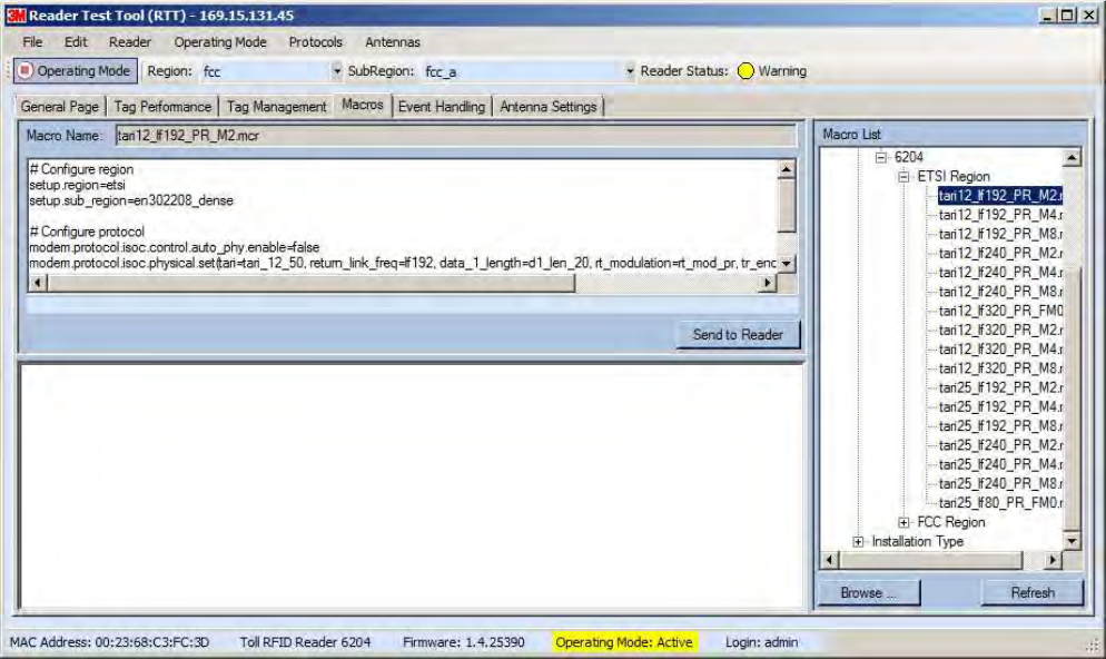
1
2
3
4
5
6
66
6
7
8
9
Reader Startup Tool
Reader Startup ToolReader Startup Tool
Reader Startup Tool
3M Toll RFID Reader 6204
3M Toll RFID Reader 62043M Toll RFID Reader 6204
3M Toll RFID Reader 6204
User’s Guide
User’s GuideUser’s Guide
User’s Guide
37
3737
37
6.5.4. Macros Page
Macros PageMacros Page
Macros Page
The Macros page allows the reader to manage macro files. The macros are
provided by 3M or can be written by the end user. Some of the macros
provided are dependent on the operating region of the reader.
A macro (script or command file) is a text file that contains one or more
reader commands. These commands are used to configure the reader to a
known configuration. The Macros can contain variables. These variables are
resolved by a dialog box (Macro Variables) that appears when the Send to
Reader button is selected. The syntax of a variable is:
[$variable_name]
During execution, the variable is replaced with user entries into the Macro
Variables dialog box. Macros can be edited with any text editor including
Windows Notepad.
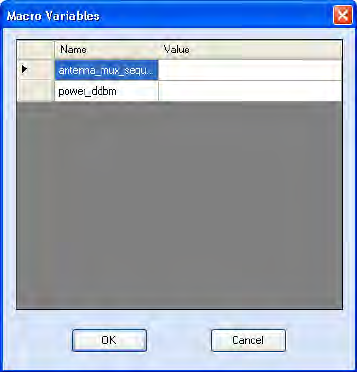
1
2
3
4
5
6
66
6
7
8
9
Reader Startup Tool
Reader Startup ToolReader Startup Tool
Reader Startup Tool
38
3838
38
3M Toll RFID Reader 6204
3M Toll RFID Reader 62043M Toll RFID Reader 6204
3M Toll RFID Reader 6204
User’s Guide
User’s GuideUser’s Guide
User’s Guide
Macro
Macro Macro
Macro Input sub
Input subInput sub
Input sub-
--
-window
windowwindow
window
The Macro Input window shows the current script that will be sent to the
reader when the Send to Reader button is selected. The text in the Macro
Input window can be edited prior to being sent to the reader.
Macro Output sub
Macro Output subMacro Output sub
Macro Output sub-
--
-window
windowwindow
window
The Macro Output window is updated after the Send to Reader button is
selected. Look at this window to verify that each command line in a script
executed correctly. Look for the −−>> ok response from the reader for each
command line.
Macro
Macro Macro
Macro Variable
VariableVariable
Variables
ss
s
Dia
DiaDia
Dialog box
log boxlog box
log box
When a macro is sent to the
reader, the values for variables
must be resolved via this Windows
Dialog box. You can [tab] to each
value field and enter the desired
value.
For example, one macro can be
used for two different applications
by using variables for antenna
selection and transmit power.
Macro Example
Macro ExampleMacro Example
Macro Example
To configure the reader for FCC, Part 90 Dense operation, send the
following macro (part90_6tari_lf640_PR_M2.mcr):
# configure region
setup.region=fcc
setup.sub_region=fcc_part90
# set frequency
setup.advanced.preferred_frequencies=915950
# configure protocol
modem.protocol.isoc.control.auto_phy.enable=false
modem.protocol.isoc.physical.set(tari=tari_06_25,
return_link_freq=LF640, data_1_length=d1_len_20,
rt_modulation=rt_mod_pr,
tr_encoding=tr_enc_miller_2,interrogator_mode=dense)
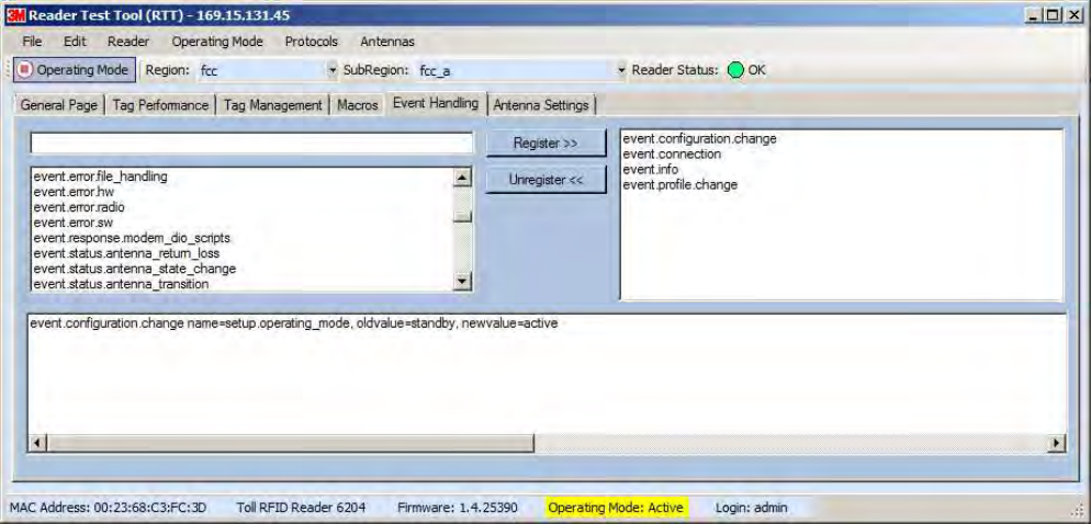
1
2
3
4
5
6
66
6
7
8
9
Reader Startup Tool
Reader Startup ToolReader Startup Tool
Reader Startup Tool
3M Toll RFID Reader 6204
3M Toll RFID Reader 62043M Toll RFID Reader 6204
3M Toll RFID Reader 6204
User’s Guide
User’s GuideUser’s Guide
User’s Guide
39
3939
39
6.5.5. Event Handling Page
Event Handling PageEvent Handling Page
Event Handling Page
The Event Handling page allows you to register for Reader Events. After
registration, events are displayed with the newest on the bottom and the
most recent event will scroll to the bottom of the window. Individual events
or a group of events can be registered. For detailed information on
individual events, refer to Chapter 18 – Events Namespace of the 3M Toll
3M Toll 3M Toll
3M Toll
RFID Reader
RFID ReaderRFID Reader
RFID Reader
6204
62046204
6204
Protocol Reference Guide
Protocol Reference GuideProtocol Reference Guide
Protocol Reference Guide.
Registering for an individua
Registering for an individuaRegistering for an individua
Registering for an individual event
l eventl event
l event
To register for an individual event, either type the event name or select an
event from a pull-down list.
Registering for a group of events
Registering for a group of eventsRegistering for a group of events
Registering for a group of events
Registering for event.error events, will cause the reader to autonomously
send all events in the event.error namespace to the RTT program and be
displayed in the window of this page. Enter event.error in the Events: field
and press the Register button. The Clear button can be selected at any
time to clear the window.
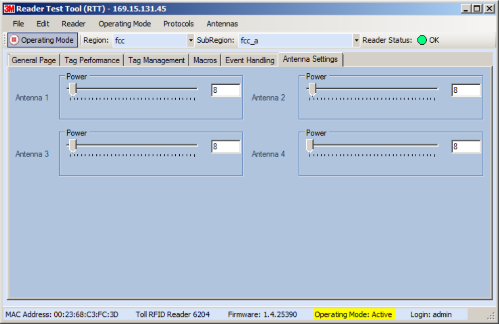
1
2
3
4
5
6
66
6
7
8
9
Reader Startup Tool
Reader Startup ToolReader Startup Tool
Reader Startup Tool
40
4040
40
3M Toll RFID Reader 6204
3M Toll RFID Reader 62043M Toll RFID Reader 6204
3M Toll RFID Reader 6204
User’s Guide
User’s GuideUser’s Guide
User’s Guide
6.5.6. Antenna Settings Page
Antenna Settings PageAntenna Settings Page
Antenna Settings Page
The Antenna Settings page allows you to adjust the power settings for each
antenna. Only the controls for those antennas that are connected are
activated.
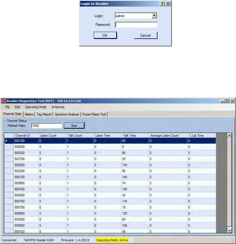
1
2
3
4
5
6
66
6
7
8
9
Reader Startup Tool
Reader Startup ToolReader Startup Tool
Reader Startup Tool
3M Toll RFID Reader 6204
3M Toll RFID Reader 62043M Toll RFID Reader 6204
3M Toll RFID Reader 6204
User’s Guide
User’s GuideUser’s Guide
User’s Guide
41
4141
41
6.6. Reader Diagnostics Tool (RDT)
Reader Diagnostics Tool (RDT)Reader Diagnostics Tool (RDT)
Reader Diagnostics Tool (RDT)
The RDT is to be used by 3M trained technicians to troubleshoot and
diagnose various reader issues. Administrator login is required.
To use RDT, you must login as an administrator, perform the following.
When you first start RDT, the following login will appear:
Enter your Password. Enter readeradmin or your current administrator
password. Press OK.
6.6.1. Channel Statistics
Channel StatisticsChannel Statistics
Channel Statistics
The Channel Stats page shows details of channel changes. This page is
typically used to observe regional behavior.
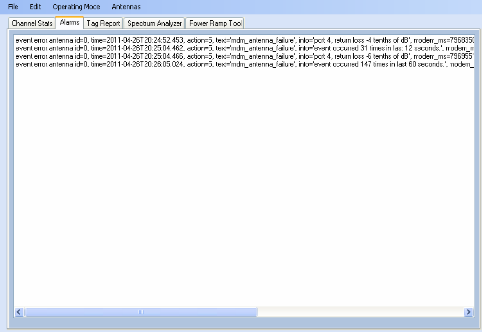
1
2
3
4
5
6
66
6
7
8
9
Reader Startup Tool
Reader Startup ToolReader Startup Tool
Reader Startup Tool
42
4242
42
3M Toll RFID Reader 6204
3M Toll RFID Reader 62043M Toll RFID Reader 6204
3M Toll RFID Reader 6204
User’s Guide
User’s GuideUser’s Guide
User’s Guide
6.6.2. Alarms
AlarmsAlarms
Alarms
The Alarms page is used to capture autonomous alarms generated by the
reader during normal operation. The alarms are defined as autonomous
reader events for the following namespaces:
event.error
event.warning
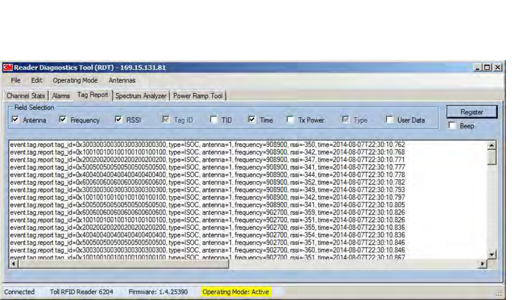
1
2
3
4
5
6
66
6
7
8
9
Reader Startup Tool
Reader Startup ToolReader Startup Tool
Reader Startup Tool
3M Toll RFID Reader 6204
3M Toll RFID Reader 62043M Toll RFID Reader 6204
3M Toll RFID Reader 6204
User’s Guide
User’s GuideUser’s Guide
User’s Guide
43
4343
43
6.6.3. Tag Report
Tag ReportTag Report
Tag Report
The Tag Report page is used to view specific information for each tag
singulation. This feature provides detailed attributes of tag singulations
such as tag power (RSSI) and on which antenna that tag singulated.
NOTICE
NOTICENOTICE
NOTICE:
::
:
Use of this tool can adversely affect tag reader performance, particularly if many tag fields are
enabled. Use the RTT->Tag Performance page for normal tag performance testing.
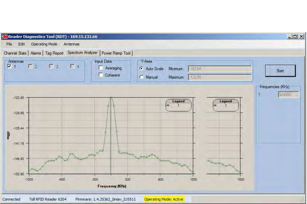
1
2
3
4
5
6
66
6
7
8
9
Reader Startup Tool
Reader Startup ToolReader Startup Tool
Reader Startup Tool
44
4444
44
3M Toll RFID Reader 6204
3M Toll RFID Reader 62043M Toll RFID Reader 6204
3M Toll RFID Reader 6204
User’s Guide
User’s GuideUser’s Guide
User’s Guide
6.6.4. Spectrum Analyzer
Spectrum AnalyzerSpectrum Analyzer
Spectrum Analyzer
The Spectrum Analyzer allows you to examine the spectral composition of
the radio waves in your surrounding environment. This feature provides a
graphical representation of the current spectral RF noise in units of dBm
with a range of 0 to -120 dBm. This feature is intended for expert users to
verify RF environmental conditions during an installation.
NOTICE
NOTICENOTICE
NOTICE:
::
:
Using this feature during normal reader operation can significantly degrade tag reading
performance.
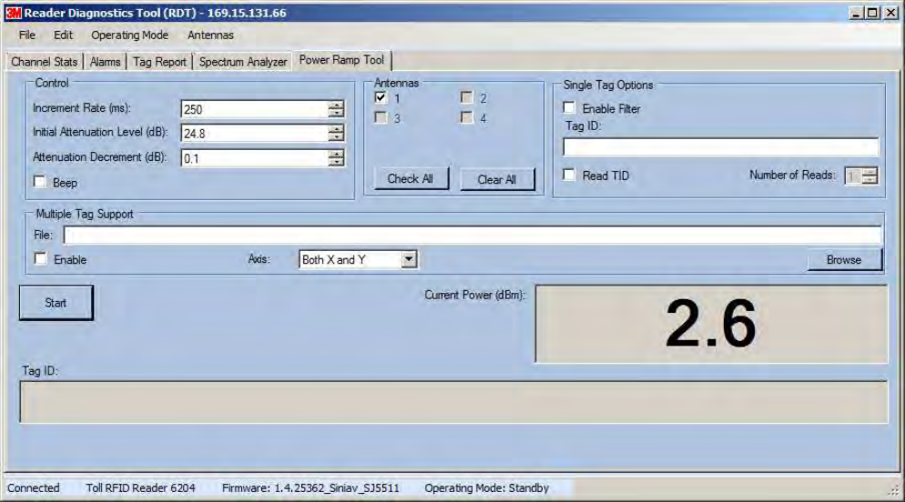
1
2
3
4
5
6
66
6
7
8
9
Reader Startup Tool
Reader Startup ToolReader Startup Tool
Reader Startup Tool
3M Toll RFID Reader 6204
3M Toll RFID Reader 62043M Toll RFID Reader 6204
3M Toll RFID Reader 6204
User’s Guide
User’s GuideUser’s Guide
User’s Guide
45
4545
45
6.6.5. Power Ramp Tool
Power Ramp ToolPower Ramp Tool
Power Ramp Tool
The Power Ramp Tool determines the minimum power to activate a tag and
can help determine tag quality. This activation power level can help
determine the read range at various attenuation levels and, for AVI
applications, can help determine the "read-zone" or an antenna pattern.
The tool starts by configuring the reader to start transmitting at a high
attenuation level (usually maximum allowed for reader) and decrements the
level until it observes a response from the tag. The transmitter is turned off
and the minimum value to activate the tag for a given antenna and distance
is reported.
The Power Ramp controls include:
Increment Rate (ms) – Time tool stays at a particular power level
before incrementing to the next power level.
Initial Attenuation Level (dBm) – Starting attenuation level.
Attenuation Decrement (dBm) – Step-size for attenuation
decrement.
Antennas section allows you to select which antenna(s) to test with.
Filter section allows you to apply a filter to only look for a particular tag.
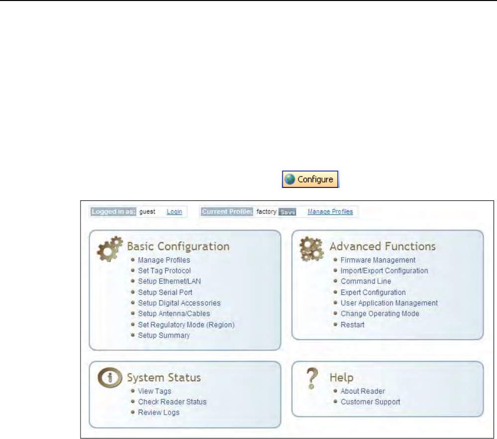
1
2
3
4
5
6
7
77
7
8
9
Reader Configuration Tool
Reader Configuration ToolReader Configuration Tool
Reader Configuration Tool
46
4646
46
3M Toll RFID Reader 6204
3M Toll RFID Reader 62043M Toll RFID Reader 6204
3M Toll RFID Reader 6204
User’s Guide
User’s GuideUser’s Guide
User’s Guide
7 Embedded Reader Configuration Tool (RCT)
The embedded Reader Configuration Tool (RCT) allows you to access your
reader across the internet by entering the reader’s IP address into your web
browser. With the RCT, you can fully configure your reader for operation in a
variety of applications and environments. With this application, you can
perform the following:
Basic Configurations
Advanced Configurations
Check System Status
Access the online Help
To access the RCT, press the button on the main RST page.

1
2
3
4
5
6
7
77
7
8
9
Reader Configuration Tool
Reader Configuration ToolReader Configuration Tool
Reader Configuration Tool
3M Toll RFID Reader 6204
3M Toll RFID Reader 62043M Toll RFID Reader 6204
3M Toll RFID Reader 6204
User’s Guide
User’s GuideUser’s Guide
User’s Guide
47
4747
47
7.1. Basic Configuration
Basic ConfigurationBasic Configuration
Basic Configuration
With the Basic Configuration functions you can perform the following:
Manage reader profiles
Set tag protocols
Setup the Ethernet/LAN configuration
Setup the serial port
Setup digital accessories
Setup antennas
Set regulatory modes
7.1.1. Configuration Page Header
Configuration Page HeaderConfiguration Page Header
Configuration Page Header
Each page displayed by the RCT has the following header.
This header provides pull-down menus for each of the configuration
function categories. Additional functions include the user login and the
currently loaded reader profile.
Login
LoginLogin
Login
The reader’s default user level is guest
guestguest
guest. However, a user can login as admin.
If not logged in as admin
adminadmin
admin, the default level is always guest
guestguest
guest.
The guest login level provides read-only access to the reader. Clients that
login in at the guest level can read the settings of the reader and can
access the tags that the reader has inventoried. Clients at this level cannot
change the configuration of the reader.
The admin login level provides read-write access to the reader. Clients that
login in at the admin level can read and write the settings of the reader and
can access the tags that the reader has inventoried.
Logout
LogoutLogout
Logout
After logging in as admin
adminadmin
admin, the Logout
LogoutLogout
Logout button logs you out of the reader.
Logging out automatically sets the login level to guest.
Profile:
Profile:Profile:
Profile:
Profile is the currently active profile in the reader. Refer to the Manage
Profiles section for detailed information on reader profiles.
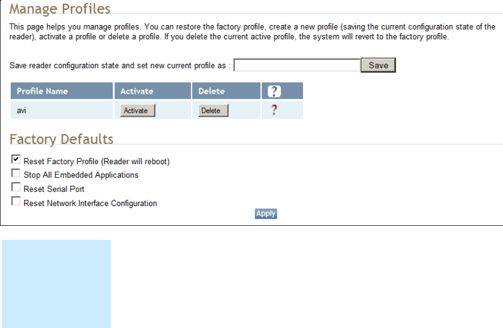
1
2
3
4
5
6
7
77
7
8
9
Reader Configuration Tool
Reader Configuration ToolReader Configuration Tool
Reader Configuration Tool
48
4848
48
3M Toll RFID Reader 6204
3M Toll RFID Reader 62043M Toll RFID Reader 6204
3M Toll RFID Reader 6204
User’s Guide
User’s GuideUser’s Guide
User’s Guide
Save
SaveSave
Save
The Save button saves the reader's current configuration to the specified
profile. Refer to the Manage Profiles section for detailed information on
reader profiles.
Manage Profiles
Manage ProfilesManage Profiles
Manage Profiles
This link allows you to list, save, and delete profiles. Refer to the Manage
Profiles section for detailed information on reader profiles.
7.1.2. Manage Profiles
Manage ProfilesManage Profiles
Manage Profiles
The reader’s configuration is stored in a profile. A profile contains the
setting of all the configuration variables in the reader. The reader can
support up to 8 unique profiles. Detailed information about reader profiles
is provided in Chapter 4 – Reader Behavior of the 3M Toll RFID Reader
3M Toll RFID Reader3M Toll RFID Reader
3M Toll RFID Reader
6204 P
6204 P6204 P
6204 Protocol Reference Guide
rotocol Reference Guiderotocol Reference Guide
rotocol Reference Guide.
The Manage Profiles page provides a list of all profiles stored in the reader.
Save a Profile
Save a ProfileSave a Profile
Save a Profile
To save your current reader configuration under a new profile, enter a
profile name and press Save. The new profile will appear in the Profile
Name list. Profile names must consist of the characters A - Z, a - z, 0 - 9, '-'
or '_' and must be between 1 and 32 characters in length. The reader can
store up to 8 different profiles.
Profile Names
Profile NamesProfile Names
Profile Names
The profile name
factory
factoryfactory
factory is reserved
and cannot be used.
This profile is a read
only profile.

1
2
3
4
5
6
7
77
7
8
9
Reader Configuration Tool
Reader Configuration ToolReader Configuration Tool
Reader Configuration Tool
3M Toll RFID Reader 6204
3M Toll RFID Reader 62043M Toll RFID Reader 6204
3M Toll RFID Reader 6204
User’s Guide
User’s GuideUser’s Guide
User’s Guide
49
4949
49
Activate a Profil
Activate a ProfilActivate a Profil
Activate a Profile
ee
e
To activate a previously saved profile, press the Activate button beside the
profile name. The selected profile will be loaded into the reader.
Delete a Profile
Delete a ProfileDelete a Profile
Delete a Profile
To delete a previously saved profile, press the Delete button beside the
profile name. This is a destructive operation. Once a profile is deleted, it
cannot be recovered.
Reset to Factory Default
Reset to Factory DefaultReset to Factory Default
Reset to Factory Default
In addition to managing reader profiles, you can also reset the reader back
to its factory default configuration. From the Profiles page select one or
more of the following:
Stop All Embedded Applications – This option terminates any
embedded applications currently running on the reader.
Reset Serial Port – This option resets the serial port configuration to
the factory default settings.
Reset Network Interface Configuration – This option resets the network
configuration to factory defaults.
NOTICE
NOTICENOTICE
NOTICE:
::
:
Resetting the 3M Toll RFID Reader 6204 to Factory Default will reboot the reader.
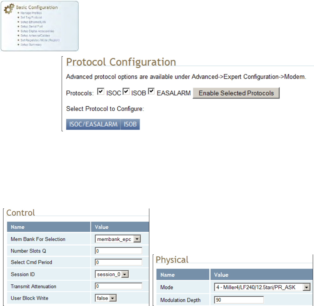
1
2
3
4
5
6
7
77
7
8
9
Reader Configuration Tool
Reader Configuration ToolReader Configuration Tool
Reader Configuration Tool
50
5050
50
3M Toll RFID Reader 6204
3M Toll RFID Reader 62043M Toll RFID Reader 6204
3M Toll RFID Reader 6204
User’s Guide
User’s GuideUser’s Guide
User’s Guide
7.1.3. Set Tag Protocol
Set Tag ProtocolSet Tag Protocol
Set Tag Protocol
This Set Tag Protocol page consists of two forms. The first form (top) allows
you to select which type of tags the reader will acquire or the type of
protocol(s) to utilize on the air interface.
Select the check box for the protocol(s) to enable and then press Enable
Selected Protocols to activate the protocol.
Click on a specific protocol to view the lower form. This form allows you to
configure various protocol level parameters. The protocol level parameters
are divided into two categories: control and physical. Control parameters
configure the protocol control. Physical parameters configure the physical
air interface for the protocol.
For detailed information on each of the Control and Physical parameters,
refer to Chapter 15 – Modem Namespace of the 3M Toll RFID Reader 6204
Protocol Reference Guide. Parameter descriptions are provided in the
modem.protocol.isoc.control and modem.protocol.isoc.physical
configuration variable sections.
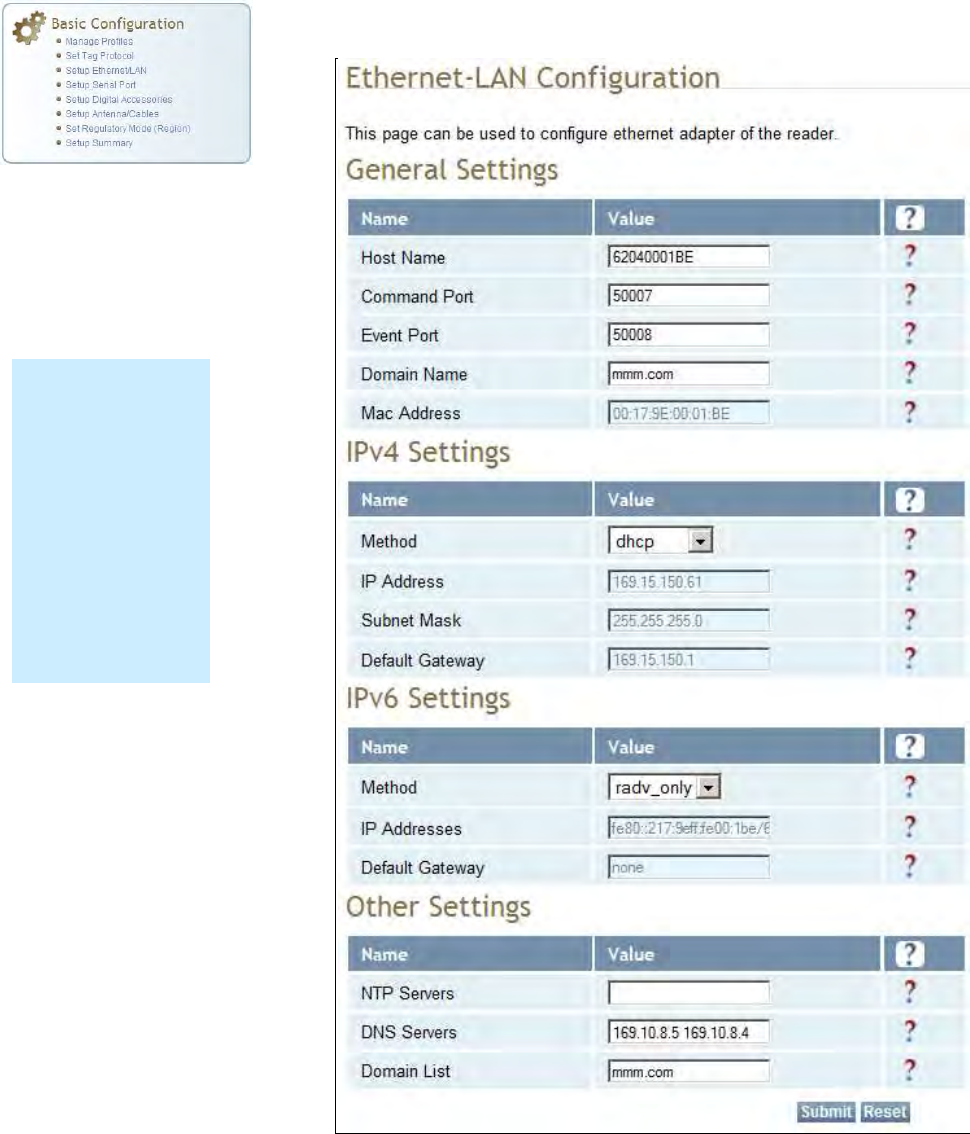
1
2
3
4
5
6
7
77
7
8
9
Reader Configuration Tool
Reader Configuration ToolReader Configuration Tool
Reader Configuration Tool
3M Toll RFID Reader 6204
3M Toll RFID Reader 62043M Toll RFID Reader 6204
3M Toll RFID Reader 6204
User’s Guide
User’s GuideUser’s Guide
User’s Guide
51
5151
51
7.1.4. Setup Ethernet/LAN
Setup Ethernet/LANSetup Ethernet/LAN
Setup Ethernet/LAN
The Setup Ethernet/LAN page allows you to configure the network interface
of the reader.
NOTE:
NOTE:NOTE:
NOTE:
Always record the
IP, Mac, subnet,
and default
gateway addresses
for your readers
and keep this data
in a safe location.
You can use this
data to reconfigure
the network in the
event of application
failure or data loss.
1
2
3
4
5
6
7
77
7
8
9
Reader Configuration Tool
Reader Configuration ToolReader Configuration Tool
Reader Configuration Tool
52
5252
52
3M Toll RFID Reader 6204
3M Toll RFID Reader 62043M Toll RFID Reader 6204
3M Toll RFID Reader 6204
User’s Guide
User’s GuideUser’s Guide
User’s Guide
General Settings allow you to specify the host and domain name of the
reader. The Command and Event Ports are also shown. You can also select
your domain name in this window.
IPv4/IPv6 Settings allow you to configure the reader’s IP address. If the
reader is to automatically acquire its IP address, subnet mask and default
gateway from a DHCP server, select Enable DHCP. To manually specify this
information, deselect Enable DHCP and fill in the desired IP address,
subnet mask and default gateway.
Other Settings allow you to configure the NTP servers the reader can
contact to obtain the current time, DNS servers the reader can contact for
domain name resolution, and the Domain list to resolve names to IP
addresses.
Enter all the required information and press Submit.
7.1.5. Setup Serial Port
Setup Serial PortSetup Serial Port
Setup Serial Port
The Setup Serial Port function allows you to configure the serial port
parameters. These parameters include:
Baud rate
Data bits
Parity
Echo
Stop bits
Use the pull-down menus to select a value and press Submit to update the
reader.
1
2
3
4
5
6
7
77
7
8
9
Reader Configuration Tool
Reader Configuration ToolReader Configuration Tool
Reader Configuration Tool
3M Toll RFID Reader 6204
3M Toll RFID Reader 62043M Toll RFID Reader 6204
3M Toll RFID Reader 6204
User’s Guide
User’s GuideUser’s Guide
User’s Guide
53
5353
53
7.1.6. Setup Digital Accessories
Setup Digital AccessoriesSetup Digital Accessories
Setup Digital Accessories
The Setup Digital Accessories function allows you to configure the Digital
Inputs and Outputs on the reader.
Digital Input
Digital InputDigital Input
Digital Input
The status of the four digital input values (1–4) can be seen in this window.
The Current Value is not configurable and is shown as true or false. The
Debounce value can be set and is in milliseconds.
Digital Output
Digital OutputDigital Output
Digital Output
The output value for each digital output can be set to true or false. Press
the Submit button to send the appropriate commands to the reader to
update the digital inputs and outputs.
Refer to the 3M Toll RFID Reader
3M Toll RFID Reader3M Toll RFID Reader
3M Toll RFID Reader
6204 P
6204 P6204 P
6204 Protocol Reference Guide
rotocol Reference Guiderotocol Reference Guide
rotocol Reference Guide for more
information on configuring the digital inputs and outputs.
1
2
3
4
5
6
7
77
7
8
9
Reader Configuration Tool
Reader Configuration ToolReader Configuration Tool
Reader Configuration Tool
54
5454
54
3M Toll RFID Reader 6204
3M Toll RFID Reader 62043M Toll RFID Reader 6204
3M Toll RFID Reader 6204
User’s Guide
User’s GuideUser’s Guide
User’s Guide
7.1.7. Setup Antenna/Cables
Setup Antenna/CablesSetup Antenna/Cables
Setup Antenna/Cables
This page allows you to configure the reader’s antenna multiplexer
sequence as well as conducted power. For detailed descriptions of each of
the antenna and cable variables, refer to Antenna Configuration in Chapter
4 – Reader Behavior of the 3M Toll RFID Reader
3M Toll RFID Reader3M Toll RFID Reader
3M Toll RFID Reader
6204 P
6204 P6204 P
6204 Protocol Reference
rotocol Reference rotocol Reference
rotocol Reference
Guide
GuideGuide
Guide.
To configure an antenna, enter the antenna number in the Mux Sequence
field. The individual antenna Conducted Power fields will be activated in
the lower window. The current values will be displayed. Only those antennas
listed in the Mux Sequence will be shown. Also, you must set Conducted
Power to 0 in order to set or change the Attenuation, Cable Loss, or Gain.
To change, enter the appropriate values for each antenna parameter and
press the Submit button to update the antenna and cable configuration.
Select the next antenna and repeat.
1
2
3
4
5
6
7
77
7
8
9
Reader Configuration Tool
Reader Configuration ToolReader Configuration Tool
Reader Configuration Tool
3M Toll RFID Reader 6204
3M Toll RFID Reader 62043M Toll RFID Reader 6204
3M Toll RFID Reader 6204
User’s Guide
User’s GuideUser’s Guide
User’s Guide
55
5555
55
ADDITIONAL ANTENNA NOTES:
ADDITIONAL ANTENNA NOTES:ADDITIONAL ANTENNA NOTES:
ADDITIONAL ANTENNA NOTES:
1. The required antenna impedance is 50 ohms.
2. To reduce potential radio interference to other users, the antenna type and its gain should be so
chosen that the equivalent isotropically radiated power (EIRP) is not more than that required for
successful communication.
3. The installer of this radio equipment must ensure that the antenna is located or pointed such that it
does not emit an RF field in excess of Health Canada limits for the general population; consult Safety
Code 6, obtainable from Health Canada’s website at:
http://www.hc-sc.gc.ca/ewh-semt/pubs/radiation/radio_guide-lignes_direct/index-eng.php.
4. Additional details for the approved antennas for the 3M Toll RFID Reader 6204 can be found in
Section 9.1.7., 3M
Section 9.1.7., 3M Section 9.1.7., 3M
Section 9.1.7., 3M Toll
TollToll
Toll
RFID Reader 6204 Antenna Specifications
RFID Reader 6204 Antenna SpecificationsRFID Reader 6204 Antenna Specifications
RFID Reader 6204 Antenna Specifications.
7.1.8. Set Regulatory Mode (Region)
Set Regulatory Mode (Region)Set Regulatory Mode (Region)
Set Regulatory Mode (Region)
This page allows the user to configure the reader to meet the regulatory
requirements for the geographic region where the reader is deployed. The
sub-region sets the secondary regulatory mode for the geographic region
where the reader is deployed.
For detailed information on each of these parameters, refer to the 3M Toll
3M Toll 3M Toll
3M Toll
RFID Reader
RFID ReaderRFID Reader
RFID Reader
6204 P
6204 P6204 P
6204 Protocol Reference Guide
rotocol Reference Guiderotocol Reference Guide
rotocol Reference Guide. Descriptions are provided in
the setup.region and setup.sub_region configuration variable
sections.
7.1.9. Setup Summary
Setup SummarySetup Summary
Setup Summary
This page allows you to quickly setup the basic operational parameters of
the reader.
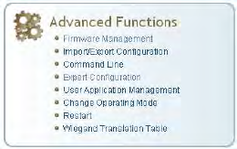
1
2
3
4
5
6
7
77
7
8
9
Reader Configuration Tool
Reader Configuration ToolReader Configuration Tool
Reader Configuration Tool
56
5656
56
3M Toll RFID Reader 6204
3M Toll RFID Reader 62043M Toll RFID Reader 6204
3M Toll RFID Reader 6204
User’s Guide
User’s GuideUser’s Guide
User’s Guide
7.2. Advanced
AdvancedAdvanced
Advanced
Functions
FunctionsFunctions
Functions
With the Advanced Functions you can perform the following:
Firmware Management
Import/Export Configuration
Command Line operations
Expert Configuration
User Application Management
Change Operating Mode
Restart
View and edit the Wiegand Translation Table
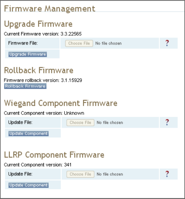
1
2
3
4
5
6
7
77
7
8
9
Reader Configuration Tool
Reader Configuration ToolReader Configuration Tool
Reader Configuration Tool
3M Toll RFID Reader 6204
3M Toll RFID Reader 62043M Toll RFID Reader 6204
3M Toll RFID Reader 6204
User’s Guide
User’s GuideUser’s Guide
User’s Guide
57
5757
57
7.2.1. Firmware
FirmwareFirmware
Firmware
Management
ManagementManagement
Management
This page allows you to perform the following:
Read the current reader firmware version
Upgrade the reader firmware files
Rollback to the previous reader firmware version
Upgrade Wiegand component firmware files (note you cannot rollback
the Wiegand firmware)
Update the LLRP Component update file and to update the LLRP
Component firmware on the reader.
Enter the name of the 3M provided firmware file in the Firmware File field.
Use the Browse button to help locate the file.
The Rollback Firmware button will roll back the reader firmware to the
previous version.
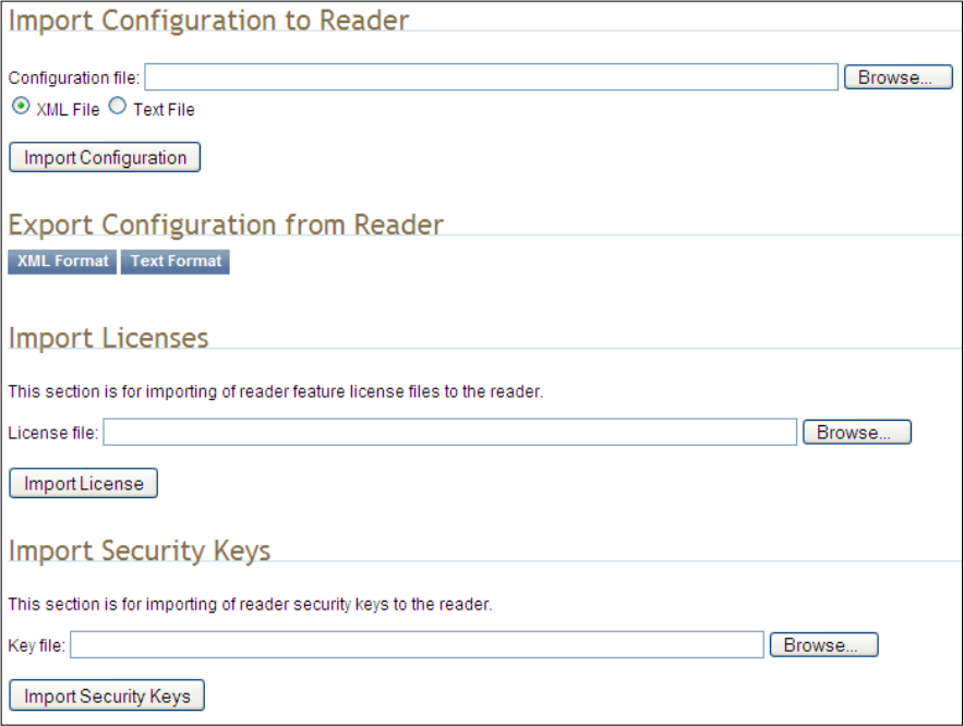
1
2
3
4
5
6
7
77
7
8
9
Reader Configuration Tool
Reader Configuration ToolReader Configuration Tool
Reader Configuration Tool
58
5858
58
3M Toll RFID Reader 6204
3M Toll RFID Reader 62043M Toll RFID Reader 6204
3M Toll RFID Reader 6204
User’s Guide
User’s GuideUser’s Guide
User’s Guide
7.2.2. Import/Export Configuration
Import/Export ConfigurationImport/Export Configuration
Import/Export Configuration
This page allows you to transfer a reader configuration to or from your host
computer. This is useful for configuring a reader to a known state.
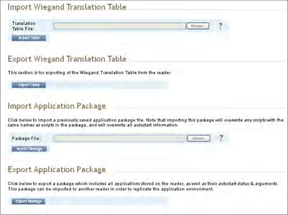
1
2
3
4
5
6
7
77
7
8
9
Reader Configuration Tool
Reader Configuration ToolReader Configuration Tool
Reader Configuration Tool
3M Toll RFID Reader 6204
3M Toll RFID Reader 62043M Toll RFID Reader 6204
3M Toll RFID Reader 6204
User’s Guide
User’s GuideUser’s Guide
User’s Guide
59
5959
59
Import
ImportImport
Import
Configuration
Configuration Configuration
Configuration to Reader
to Readerto Reader
to Reader
Enter the name of a saved configuration file in the Configuration file field.
Select the XML File option and press the Transfer Configuration to Reader
button to send the profile to the reader.
Export Configuration from Reader
Export Configuration from ReaderExport Configuration from Reader
Export Configuration from Reader
This function is used to export the current reader settings for later
uploading. Press the XML Format button to view the XML file in the browser.
Save this file to your computer if you wish retain it for future.
If you wish to view the current configuration parameters for a reader, press
Text Format button.
1
2
3
4
5
6
7
77
7
8
9
Reader Configuration Tool
Reader Configuration ToolReader Configuration Tool
Reader Configuration Tool
60
6060
60
3M Toll RFID Reader 6204
3M Toll RFID Reader 62043M Toll RFID Reader 6204
3M Toll RFID Reader 6204
User’s Guide
User’s GuideUser’s Guide
User’s Guide
Import Licenses
Import LicensesImport Licenses
Import Licenses
This function is used to import a feature license file. Navigate to the license
file and press Import License to load the file into the reader.
Import Security Keys
Import Security KeysImport Security Keys
Import Security Keys
This function is used to import reader security keys to the reader. Navigate
to the key file and press Import Security Keys to load the file into the
reader.
Export Security Keys
Export Security KeysExport Security Keys
Export Security Keys
This function is used to export reader security keys from the reader. Enter
the commissioning password and the mac address file containing a list of
readers (each number followed by a carriage return) to allow import of these
keys. Navigate to the mac address file and press Export Security Keys to
load the file into the reader.
Import Wiegand Translation Table
Import Wiegand Translation TableImport Wiegand Translation Table
Import Wiegand Translation Table
This function is used to import a Wiegand translation table to the reader.
The file will typically have a .csv extension.
Export Wiegand Translation Table
Export Wiegand Translation TableExport Wiegand Translation Table
Export Wiegand Translation Table
This function is used to export a Wiegand translation table from the reader.
The file extension will default to .csv.
Import Application Package
Import Application PackageImport Application Package
Import Application Package
This function is used to import a set of user applications, along with each
application's arguments and autostart status.
Export Application Package
Export Application PackageExport Application Package
Export Application Package
This function is used to export the user applications, along with each
application's arguments and autostart status.
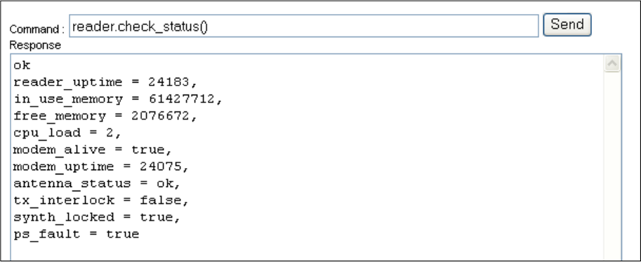
1
2
3
4
5
6
7
77
7
8
9
Reader Configuration Tool
Reader Configuration ToolReader Configuration Tool
Reader Configuration Tool
3M Toll RFID Reader 6204
3M Toll RFID Reader 62043M Toll RFID Reader 6204
3M Toll RFID Reader 6204
User’s Guide
User’s GuideUser’s Guide
User’s Guide
61
6161
61
7.2.3. Command Line
Command LineCommand Line
Command Line
This page allows you to directly enter reader commands from your web
browser.To directly enter commands from the Command Line Interface
(CLI), refer to the 3M Toll
3M Toll3M Toll
3M Toll
RFID Reader
RFID ReaderRFID Reader
RFID Reader
6204 P
6204 P6204 P
6204 Protocol Reference Guide
rotocol Reference Guiderotocol Reference Guide
rotocol Reference Guide.
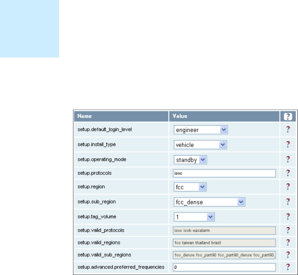
1
2
3
4
5
6
7
77
7
8
9
Reader Configuration Tool
Reader Configuration ToolReader Configuration Tool
Reader Configuration Tool
62
6262
62
3M Toll RFID Reader 6204
3M Toll RFID Reader 62043M Toll RFID Reader 6204
3M Toll RFID Reader 6204
User’s Guide
User’s GuideUser’s Guide
User’s Guide
7.3. Expert Configuration
Expert ConfigurationExpert Configuration
Expert Configuration
The Expert Configuration functions allow you to configure low-level functions
within the reader. These functions should only accessed by expert users.
Expert configurations include:
Setup
Tag
Version
Information
Communication
Antennas
Digital I/O
Security
Writeback
Modem
7.3.1. Expert Configuration
Expert ConfigurationExpert Configuration
Expert Configuration
–
––
–
Setup
SetupSetup
Setup
This page allows you to set the basic operating parameters of the reader
including region, sub region, mode, and active protocols. You can also view
the valid protocols and regions.
NOTE
NOTENOTE
NOTE
For details on
reader variables,
refer to the 3M Toll
RFID Reader 6204
Protocol Reference
Guide.
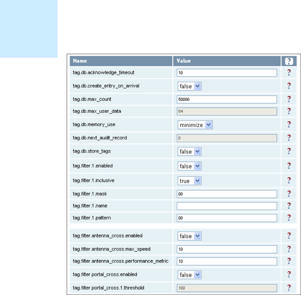
1
2
3
4
5
6
7
77
7
8
9
Reader Configuration Tool
Reader Configuration ToolReader Configuration Tool
Reader Configuration Tool
3M Toll RFID Reader 6204
3M Toll RFID Reader 62043M Toll RFID Reader 6204
3M Toll RFID Reader 6204
User’s Guide
User’s GuideUser’s Guide
User’s Guide
63
6363
63
7.3.2. Expert Configuration
Expert ConfigurationExpert Configuration
Expert Configuration
–
––
–
Tag
TagTag
Tag
This page allows you to configure how the reader reports tags.
The 6204 supports the ability to filter tags or eliminate tags from being
reported based on the conditions specified in the filter configuration
variables. The reader supports eight filters and each filter is specified by the
following configuration variables:
enabled – Enables or disables the filter.
inclusive – Indicates to either include tags that match (Inclusive) or
include tags that do not match (Exclusive) the tag filter.
mask – Mask (as an array of hex bytes) for the tag filter.
name – Name given to the tag filter
pattern – Pattern (as an array of hex bytes) for the tag filter
The following figure shows a small sample of the available variables.
NOTE
NOTENOTE
NOTE
For details on tag
variables, refer to
the 3M Toll RFID
Reader 6204
Protocol Reference
Guide.
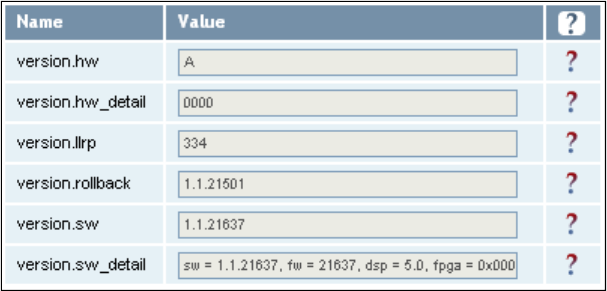
1
2
3
4
5
6
7
77
7
8
9
Reader Configuration Tool
Reader Configuration ToolReader Configuration Tool
Reader Configuration Tool
64
6464
64
3M Toll RFID Reader 6204
3M Toll RFID Reader 62043M Toll RFID Reader 6204
3M Toll RFID Reader 6204
User’s Guide
User’s GuideUser’s Guide
User’s Guide
7.3.3. Expert
Expert Expert
Expert Configuration
ConfigurationConfiguration
Configuration
–
––
–
Version
VersionVersion
Version
This page displays the version of reader hardware and reader software
within the reader. The version numbers are read-only and will be needed if
you contact 3M for technical support.
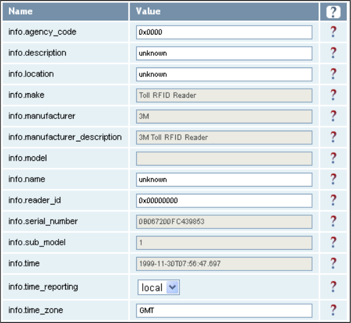
1
2
3
4
5
6
7
77
7
8
9
Reader Configuration Tool
Reader Configuration ToolReader Configuration Tool
Reader Configuration Tool
3M Toll RFID Reader 6204
3M Toll RFID Reader 62043M Toll RFID Reader 6204
3M Toll RFID Reader 6204
User’s Guide
User’s GuideUser’s Guide
User’s Guide
65
6565
65
7.3.4. Expert Configuration
Expert ConfigurationExpert Configuration
Expert Configuration
–
––
–
Information
InformationInformation
Information
This page allows you to customize the reader’s identity. You can assign
each reader a name, description, location, and zone. You can also set how
the reader reports timestamps.
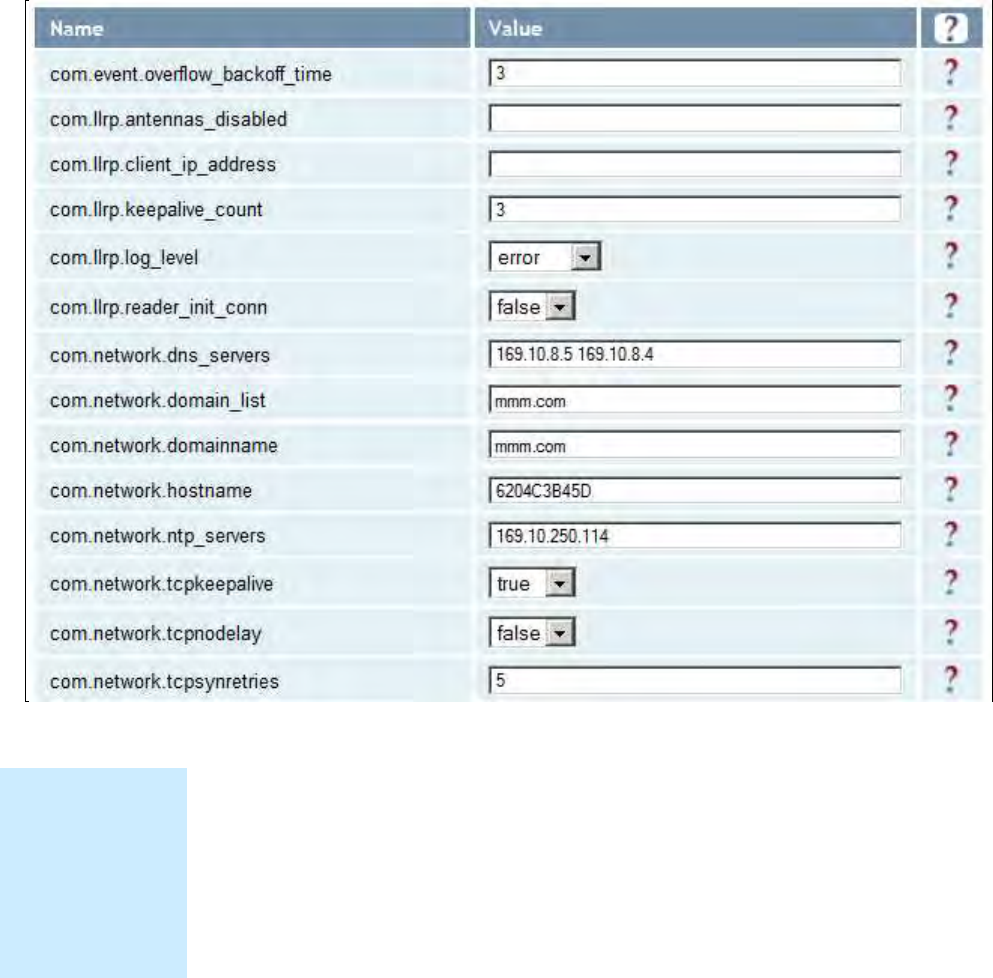
1
2
3
4
5
6
7
77
7
8
9
Reader Configuration Tool
Reader Configuration ToolReader Configuration Tool
Reader Configuration Tool
66
6666
66
3M Toll RFID Reader 6204
3M Toll RFID Reader 62043M Toll RFID Reader 6204
3M Toll RFID Reader 6204
User’s Guide
User’s GuideUser’s Guide
User’s Guide
7.3.5. Expert Configuration
Expert Configuration Expert Configuration
Expert Configuration –
––
–
Communication
CommunicationCommunication
Communication
This page allows you to customize the reader’s communication parameters.
Refer to the Setup Ethernet/LAN
Setup Ethernet/LANSetup Ethernet/LAN
Setup Ethernet/LAN and Setup Serial Port
Setup Serial PortSetup Serial Port
Setup Serial Port sections for
additional information.
The following figure shows a portion of communication parameters
available on the reader.
NOTE
NOTENOTE
NOTE
For details on
communication
parameters, refer
to the 3M Toll
RFID Reader
6204 Protocol
Reference Guide.
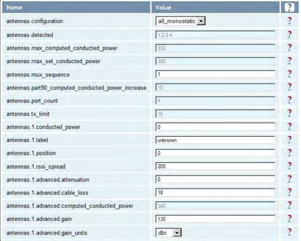
1
2
3
4
5
6
7
77
7
8
9
Reader Configuration Tool
Reader Configuration ToolReader Configuration Tool
Reader Configuration Tool
3M Toll RFID Reader 6204
3M Toll RFID Reader 62043M Toll RFID Reader 6204
3M Toll RFID Reader 6204
User’s Guide
User’s GuideUser’s Guide
User’s Guide
67
6767
67
7.3.6. Expert Configuration
Expert Configuration Expert Configuration
Expert Configuration –
––
–
Antennas
AntennasAntennas
Antennas
This page allows you to configure the properties of the reader’s antenna
configuration. For detailed description of each of the antenna and cable
variables, refer to the Antenna Configuration section in Chapter 4 – Reader
Behavior of the 3M Toll RFID Reader
3M Toll RFID Reader3M Toll RFID Reader
3M Toll RFID Reader
6204 P
6204 P6204 P
6204 Protocol Reference Guide
rotocol Reference Guiderotocol Reference Guide
rotocol Reference Guide.
Enter the appropriate values for each antenna parameter and press the
Submit button to update the antenna and cable configuration. Only
Antenna 1 and common antenna variables shown.
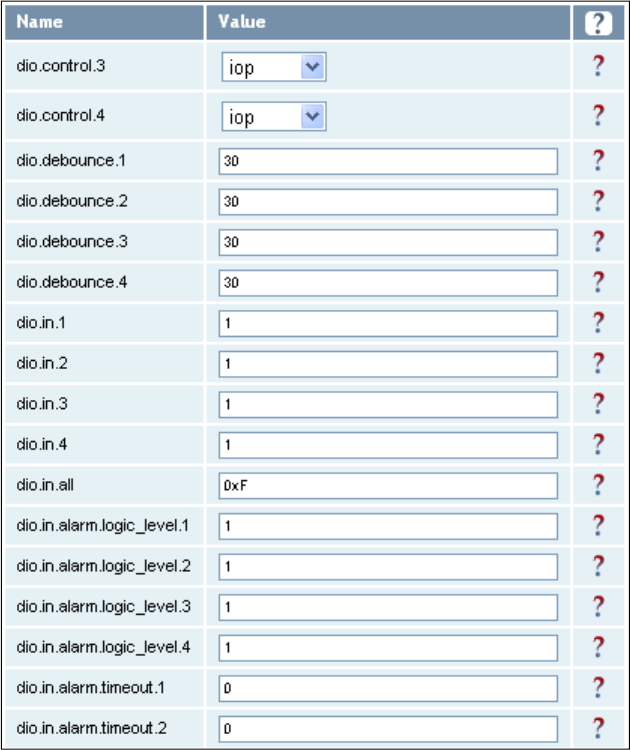
1
2
3
4
5
6
7
77
7
8
9
Reader Configuration Tool
Reader Configuration ToolReader Configuration Tool
Reader Configuration Tool
68
6868
68
3M Toll RFID Reader 6204
3M Toll RFID Reader 62043M Toll RFID Reader 6204
3M Toll RFID Reader 6204
User’s Guide
User’s GuideUser’s Guide
User’s Guide
7.3.7. Expert Configuration
Expert Configuration Expert Configuration
Expert Configuration –
––
–
Digital I/O
Digital I/ODigital I/O
Digital I/O
This page allows you to configure the digital inputs and output behavior. You
can set the digital input debounce time (in milliseconds), as well as the
input and output pin values. Refer to the
3M Toll RFID Reader
3M Toll RFID Reader3M Toll RFID Reader
3M Toll RFID Reader
6204
6204 6204
6204
P
PP
Protocol Reference Guide
rotocol Reference Guiderotocol Reference Guide
rotocol Reference Guide
for detailed information on each of these
variables.
1
2
3
4
5
6
7
77
7
8
9
Reader Configuration Tool
Reader Configuration ToolReader Configuration Tool
Reader Configuration Tool
3M Toll RFID Reader 6204
3M Toll RFID Reader 62043M Toll RFID Reader 6204
3M Toll RFID Reader 6204
User’s Guide
User’s GuideUser’s Guide
User’s Guide
69
6969
69
7.3.8. Expert Configuration
Expert Configuration Expert Configuration
Expert Configuration –
––
–
Security
SecuritySecurity
Security
This page allows you to configure the tag.security parameters.
Refer to the
3M Toll RFID Reader
3M Toll RFID Reader3M Toll RFID Reader
3M Toll RFID Reader
6204 P
6204 P6204 P
6204 Protocol Reference Guide
rotocol Reference Guiderotocol Reference Guide
rotocol Reference Guide
for
detailed information on each of these variables.
1
2
3
4
5
6
7
77
7
8
9
Reader Configuration Tool
Reader Configuration ToolReader Configuration Tool
Reader Configuration Tool
70
7070
70
3M Toll RFID Reader 6204
3M Toll RFID Reader 62043M Toll RFID Reader 6204
3M Toll RFID Reader 6204
User’s Guide
User’s GuideUser’s Guide
User’s Guide
7.3.9. Expert Configurati
Expert ConfiguratiExpert Configurati
Expert Configuration
on on
on –
––
–
Writeback
WritebackWriteback
Writeback
This page allows you to configure the tag.writeback parameters.
Refer to the
3M Toll RFID Reader
3M Toll RFID Reader3M Toll RFID Reader
3M Toll RFID Reader
6204 P
6204 P6204 P
6204 Protocol Reference Guide
rotocol Reference Guiderotocol Reference Guide
rotocol Reference Guide
for
detailed information on each of these variables.
1
2
3
4
5
6
7
77
7
8
9
Reader Configuration Tool
Reader Configuration ToolReader Configuration Tool
Reader Configuration Tool
3M Toll RFID Reader 6204
3M Toll RFID Reader 62043M Toll RFID Reader 6204
3M Toll RFID Reader 6204
User’s Guide
User’s GuideUser’s Guide
User’s Guide
71
7171
71
7.3.10. Expert Configuration
Expert Configuration Expert Configuration
Expert Configuration –
––
–
Modem
ModemModem
Modem
This page allows you to set the reader’s modem variables. Modem variables
are divided into the following categories:
Control
Debug
Diagnostics
Digital IO
Radio
Statistics
Refer to the 3M Toll RFID Reader
3M Toll RFID Reader3M Toll RFID Reader
3M Toll RFID Reader
6204 P
6204 P6204 P
6204 Protocol Reference Guide
rotocol Reference Guiderotocol Reference Guide
rotocol Reference Guide for
detailed information on each of these variables. The following figures show
only a small sample of the available modem configuration variables.
7.3.10.1. Modem – Control
1
2
3
4
5
6
7
77
7
8
9
Reader Configuration Tool
Reader Configuration ToolReader Configuration Tool
Reader Configuration Tool
72
7272
72
3M Toll RFID Reader 6204
3M Toll RFID Reader 62043M Toll RFID Reader 6204
3M Toll RFID Reader 6204
User’s Guide
User’s GuideUser’s Guide
User’s Guide
7.3.10.2. Modem – Debug
7.3.10.3. Modem – Diagnostics
7.3.10.4. Modem – Digital IO
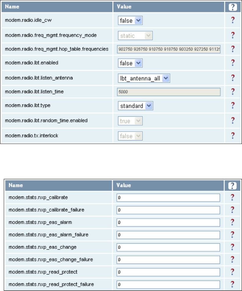
1
2
3
4
5
6
7
77
7
8
9
Reader Configuration Tool
Reader Configuration ToolReader Configuration Tool
Reader Configuration Tool
3M Toll RFID Reader 6204
3M Toll RFID Reader 62043M Toll RFID Reader 6204
3M Toll RFID Reader 6204
User’s Guide
User’s GuideUser’s Guide
User’s Guide
73
7373
73
7.3.10.5. Modem – Radio
7.3.10.6. Modem – Statistics
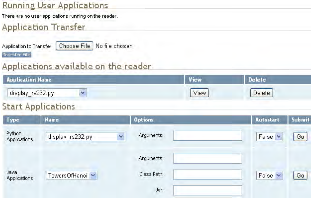
1
2
3
4
5
6
7
77
7
8
9
Reader Configuration Tool
Reader Configuration ToolReader Configuration Tool
Reader Configuration Tool
74
7474
74
3M Toll RFID Reader 6204
3M Toll RFID Reader 62043M Toll RFID Reader 6204
3M Toll RFID Reader 6204
User’s Guide
User’s GuideUser’s Guide
User’s Guide
7.4. U
UU
User
ser ser
ser Application Management
Application ManagementApplication Management
Application Management
This page lists any user applications currently available on the reader and if
any applications are running. This page also allows you to upload
applications to the reader.
Running User Applications
Running User ApplicationsRunning User Applications
Running User Applications – Lists any user applications currently
running on the reader. The application name, process ID, configuration,
and status are provided. Controls are provided to view the application
file and stop the application.
Application Transfer
Application TransferApplication Transfer
Application Transfer – This function allows you to load custom user
applications onto the reader.
Applications available on the reader
Applications available on the readerApplications available on the reader
Applications available on the reader – This function allows you to view a
list of all user applications stored on the reader. Controls are provided
to view the application and delete it from the reader.
Start Applications
Start Applications Start Applications
Start Applications – This function allows you to start Python and Java
applications.
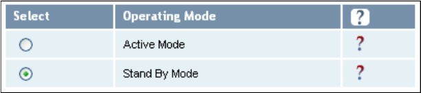
1
2
3
4
5
6
7
77
7
8
9
Reader Configuration Tool
Reader Configuration ToolReader Configuration Tool
Reader Configuration Tool
3M Toll RFID Reader 6204
3M Toll RFID Reader 62043M Toll RFID Reader 6204
3M Toll RFID Reader 6204
User’s Guide
User’s GuideUser’s Guide
User’s Guide
75
7575
75
7.5. Change Operating Mode
Change Operating ModeChange Operating Mode
Change Operating Mode
This page allows you to configure the operational mode of the reader.
The reader supports the following operational modes:
Active Mode
Active ModeActive Mode
Active Mode - Reader is continuously attempting to singulate tags and
automatically reports any singulated tag via an asynchronous event
notification on the event channel.
S
SS
Stand
tandtand
tand
B
BB
By
yy
y
Mode
ModeMode
Mode - Reader is not transmitting any energy, unless
processing a tag related command. The RF transmitter is enabled at the
beginning of the command processing, any protocol operations required
for the command are performed, and then the RF transmitter is turned
back off.
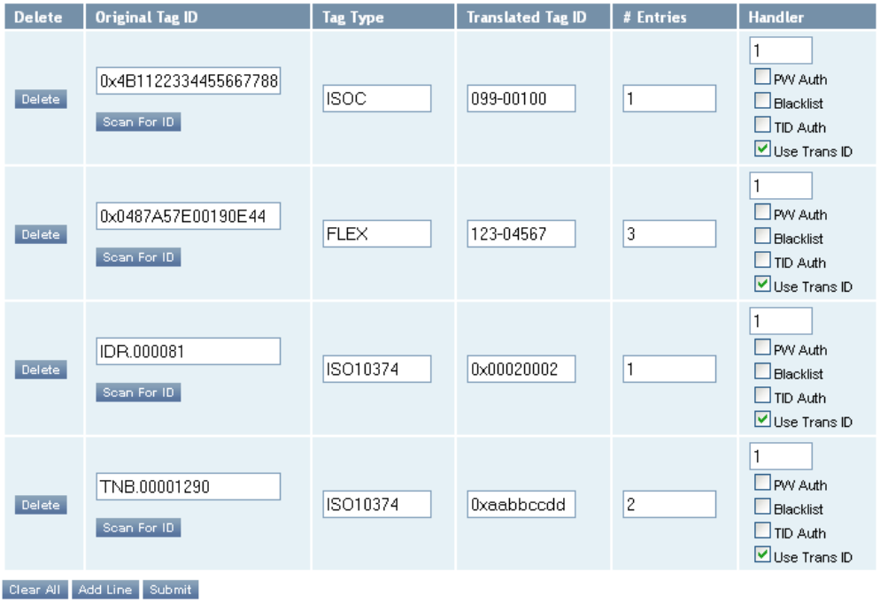
1
2
3
4
5
6
7
77
7
8
9
Reader Configuration Tool
Reader Configuration ToolReader Configuration Tool
Reader Configuration Tool
76
7676
76
3M Toll RFID Reader 6204
3M Toll RFID Reader 62043M Toll RFID Reader 6204
3M Toll RFID Reader 6204
User’s Guide
User’s GuideUser’s Guide
User’s Guide
7.6. Wiegand Translation Table
Wiegand Translation TableWiegand Translation Table
Wiegand Translation Table
This page allows you to view and edit the Translation Table used for
Wiegand operation and also for the Standalone Access Control script.
The table is only displayed when the Wiegand component is active (when
com.wiegand.enable is set to true). Buttons allow you to edit existing
translation table entries, add new entries, or delete existing entries. You
must click Submit to save table changes to the reader.
The Scan For ID button may be used to operate the reader briefly and
populate the "Original Tag ID" field with the first tag ID seen. Please see
Appendix A for details on the format of the translation table.
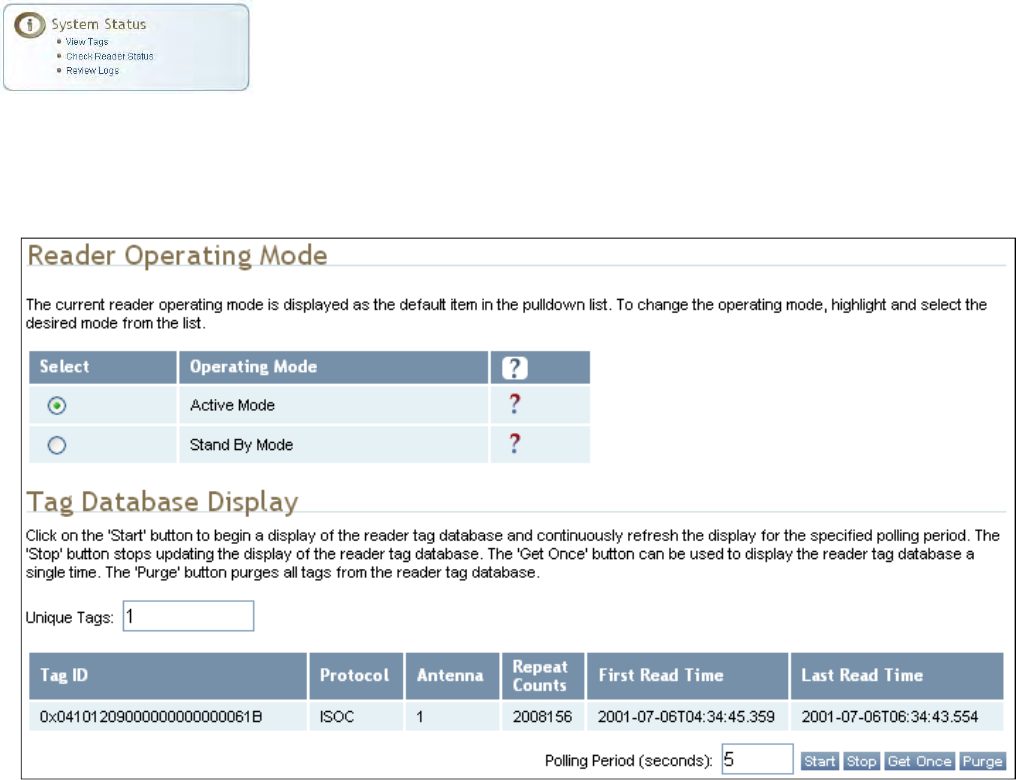
1
2
3
4
5
6
7
77
7
8
9
Reader Configuration Tool
Reader Configuration ToolReader Configuration Tool
Reader Configuration Tool
3M Toll RFID Reader 6204
3M Toll RFID Reader 62043M Toll RFID Reader 6204
3M Toll RFID Reader 6204
User’s Guide
User’s GuideUser’s Guide
User’s Guide
77
7777
77
7.7. View Tags
View TagsView Tags
View Tags
All tags read by the reader are stored in a database on the reader. This
page allows you to view the tags in the database as well as change the
current Operating Mode (A
AA
Active
ctivective
ctive or S
SS
Stand
tandtand
tand
B
BB
By
yy
y).
Press Start
StartStart
Start to begin displaying the tag database. This page is automatically
refreshed every five seconds. Press Get Once
Get OnceGet Once
Get Once to update the database one
time (refresh is off). Press Purge
PurgePurge
Purge to purge all tags from the database.
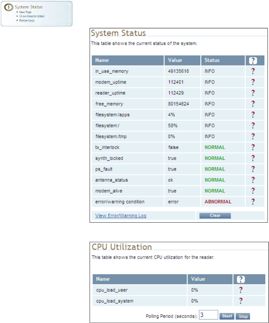
1
2
3
4
5
6
7
77
7
8
9
Reader Configuration Tool
Reader Configuration ToolReader Configuration Tool
Reader Configuration Tool
78
7878
78
3M Toll RFID Reader 6204
3M Toll RFID Reader 62043M Toll RFID Reader 6204
3M Toll RFID Reader 6204
User’s Guide
User’s GuideUser’s Guide
User’s Guide
7.8. Check Reader Status
Check Reader StatusCheck Reader Status
Check Reader Status
This page allows you to view the reader/system status, CPU utilization,
services, and licensed features. This information can be used by 3M
Technical Support to verify reader operation.
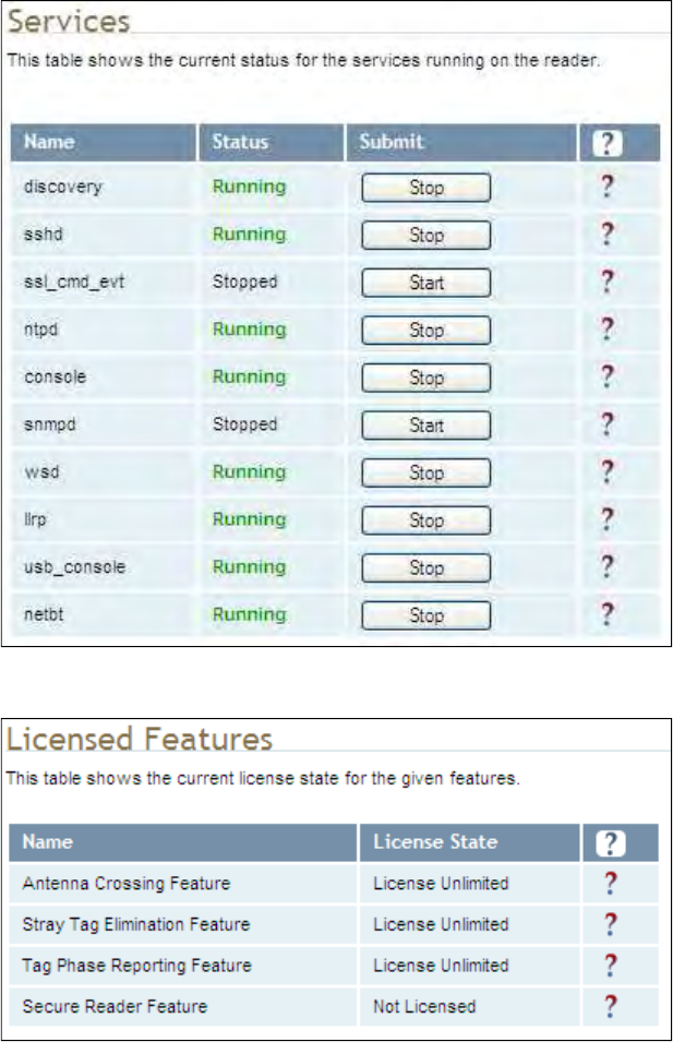
1
2
3
4
5
6
7
77
7
8
9
Reader Configuration Tool
Reader Configuration ToolReader Configuration Tool
Reader Configuration Tool
3M Toll RFID Reader 6204
3M Toll RFID Reader 62043M Toll RFID Reader 6204
3M Toll RFID Reader 6204
User’s Guide
User’s GuideUser’s Guide
User’s Guide
79
7979
79
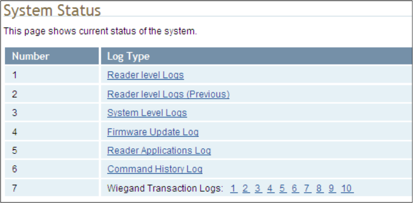
1
2
3
4
5
6
7
77
7
8
9
Reader Configuration Tool
Reader Configuration ToolReader Configuration Tool
Reader Configuration Tool
80
8080
80
3M Toll RFID Reader 6204
3M Toll RFID Reader 62043M Toll RFID Reader 6204
3M Toll RFID Reader 6204
User’s Guide
User’s GuideUser’s Guide
User’s Guide
7.9. Review Logs
Review LogsReview Logs
Review Logs
This page allows you to view the reader logs. These logs can be used by 3M
Technical Support to verify reader operation. The reader logs include:
Reader level Logs – System level reader operation
System Level Logs – Linux logs
Firmware Update Log – System level
Reader Applications Log – User application logs
Command History Log – Recent commands sent to the reader
Wiegand Translation Logs – Logs associated with the translation
tables for the Wiegand Interface Module

1
2
3
4
5
6
7
8
88
8
9
Configuring Digital I/Os
Configuring Digital I/OsConfiguring Digital I/Os
Configuring Digital I/Os
3M Toll RFID Reader 6204
3M Toll RFID Reader 62043M Toll RFID Reader 6204
3M Toll RFID Reader 6204
User’s Guide
User’s GuideUser’s Guide
User’s Guide
81
8181
81
8 Configuring Digital Inputs and Outputs
8.1. Digital Inputs
Digital InputsDigital Inputs
Digital Inputs
The digital inputs (DIN1 – DIN4) can be used as general purpose inputs or
to trigger the reader for tag reading. Unused or open digital inputs are
floating inside the reader.
To activate the input, pull it low (0 Vdc) with an external device or
connection to ground that can sink 2.5 mA. No voltage higher than +24 Vdc
or lower than 0 Vdc should ever be connected to the input. See Figure 5 for
an example of a typical motion sensor installed as a tag read trigger device.
8.2. Digital Outputs
Digital OutputsDigital Outputs
Digital Outputs
The digital outputs (DOUT1 – DOUT4) can be used as general purpose
outputs, to indicate tag reading activity, or to indicate the reader is
transmitting (RF On). Digital outputs can be pulled high.
No voltage higher than +40 Vdc or lower than 0 Vdc should ever be
connected to a digital output. The reader activates the output by pulling it
low (0 Vdc) and can sink current such that power dissipation is ≤ 1W.
8.3. Low Latency Digital Input/Output Operation
Low Latency Digital Input/Output OperationLow Latency Digital Input/Output Operation
Low Latency Digital Input/Output Operation
The 6204 is equipped with low-latency digital inputs and outputs. The
inputs (3 and 4) can be used by the modem to trigger low-latency events.
Two commands control these inputs as follows:
modem.dio.in.X.positive_level = Y -- if X goes high, it triggers Y
modem.dio.in.X.negative_level = Y -- if X goes low, it triggers Y
where Y can be:
NOOP (default)
ACTIVE_MODE
STANDBY_MODE
TOGGLE_MODE
ONE_ROUND (performs one inventory round, nonblock)
RUN_SCRIPT (runs series of modem commands, see the following)
Digital I/O Module
Digital I/O ModuleDigital I/O Module
Digital I/O Module
An optional Digital
I/O Module is
available for the
3M Toll RFID
Reader 6204.
Refer to Appendix A
for more
information.
1
2
3
4
5
6
7
8
88
8
9
Configuring Digital I/Os
Configuring Digital I/OsConfiguring Digital I/Os
Configuring Digital I/Os
82
8282
82
3M Toll RFID Reader 6204
3M Toll RFID Reader 62043M Toll RFID Reader 6204
3M Toll RFID Reader 6204
User’s Guide
User’s GuideUser’s Guide
User’s Guide
Any time the RUN_SCRIPT operation is invoked, the reader will sequence
through a maximum of 10 modem commands as follows:
modem.dio.in.X.script.num_cmds = Q
modem.dio.in.X.script.cmd1 = Z
modem.dio.in.X.script.cmd2 = Z
modem.dio.in.X.script.cmd3 = Z
.
.
.
modem.dio.in.X.script.cmd10 = Z
where:
Q is the number of commands. Q can be 0 to 10 (maximum 10
modem commands).
Z can be any modem command
An event event.response.modem_dio_scripts dio_in=*,
cmdnum=*, resp=*** is generated after each modem command.
Digital outputs 3 and 4 can be driven by modem after setting the following:
dio.control.X = modem
Actions that triggered the output can be defined by:
modem.dio.out.X.op = Y
where Y can be:
NOOP (default)
END_OF_ROUND (generates a pulse at end of each inventory round)
ACTIVE_MODE (triggers high in active mode)
SCRIPT_RUNNING (triggers high when digital input io triggered
script is running)
ANTENNA_FAILURE (triggers high in antenna failure state)
ERROR (generates a pulse when an error occurs)
WARNING (generates a pulse when an warning occurs)
All output (level/pulse) polarity is defined by:
modem.dio.out.X.polarity = Z
where Z can be:
POSITIVE (default)
NEGATIVE
All pulse width (in µSec) is defined by:
modem.dio.out.X.pulse_width –(default 100 µSec)
1
2
3
4
5
6
7
8
88
8
9
Configuring Digital I/Os
Configuring Digital I/OsConfiguring Digital I/Os
Configuring Digital I/Os
3M Toll RFID Reader 6204
3M Toll RFID Reader 62043M Toll RFID Reader 6204
3M Toll RFID Reader 6204
User’s Guide
User’s GuideUser’s Guide
User’s Guide
83
8383
83
Example (Input)
Example (Input)Example (Input)
Example (Input)
The following example triggers a series of modem commands, when DIO
input 4 goes high.
modem.dio.in.4.positive_level = RUN_SCRIPT
modem.dio.in.4.script.num_cmds = 3
modem.dio.in.4.script.cmd1 = "modem.antennas.perform_check()"
modem.dio.in.4.script.cmd2 = "modem.diag.current_temperature"
modem.dio.in.4.script.cmd3 = "modem.stats.tag_read"
Example (Output
Example (OutputExample (Output
Example (Output)
))
)
In the following example, DIO output 3 will trigger low when the reader is in
active mode.
dio.control.3 = modem
modem.dio.out.3.op = ACTIVE_MODE
modem.dio.out.3.polarity = NEGATIVE
8.4. Digital I
Digital IDigital I
Digital I/O Monitoring and Control Scripts
/O Monitoring and Control Scripts/O Monitoring and Control Scripts
/O Monitoring and Control Scripts
Several digital I/O monitoring and control scripts are provided with the
reader to allow you to monitor the digital I/Os and take specific actions.
These Python application scripts can be used as is or modified to suit your
particular application. For detailed information on loading Python scripts,
refer to Chapter 5 – Embedded Reader Applications of the 3M Toll RFID
3M Toll RFID 3M Toll RFID
3M Toll RFID
Reader
ReaderReader
Reader
6204 P
6204 P6204 P
6204 Protocol Reference Guide
rotocol Reference Guiderotocol Reference Guide
rotocol Reference Guide.
8.4.1. scan_trigger.py
scan_trigger.pyscan_trigger.py
scan_trigger.py
This routine monitors the state of the digital input pin specified as the input
parameter. If the state of the pin is low, the operating mode is set to standby. If
the I/O pin state changes to high, the operating mode is set to active.
Inputs: <pin> – (optional) Input pin number (1–4). Default is digital in 1.
<trigger logic level> –(optional) 0 or 1. Default is trigger on 1.
Examples:
scan_trigger.py Monitors digital input pin 1
scan_trigger.py 1 Monitors digital input pin 1
scan_trigger.py 4 Monitors digital input pin 4
scan_trigger.py 3 0 Monitors digital input pin 3, trigger on 0
1
2
3
4
5
6
7
8
88
8
9
Configuring Digital I/Os
Configuring Digital I/OsConfiguring Digital I/Os
Configuring Digital I/Os
84
8484
84
3M Toll RFID Reader 6204
3M Toll RFID Reader 62043M Toll RFID Reader 6204
3M Toll RFID Reader 6204
User’s Guide
User’s GuideUser’s Guide
User’s Guide
8.4.2. scan_trigger_timer.py
scan_trigger_timer.pyscan_trigger_timer.py
scan_trigger_timer.py
This routine monitors the I/O pin. When the pen goes high, the timer is started
and the operating mode is set to active. While the timer is running, I/O pin state
changes are ignored. When the timer expires, the operating mode is set to
standby. The minimum value for the timer is 10 milliseconds (ms).
Inputs: <pin> – (optional) Output pin number (1–4). Default is output 1.
<time> – (optional) Time, in ms for timer to run. Default is 1000 ms.
<trigger logic level> –(optional) 0 or 1. Default is trigger on 1.
Examples:
scan_trigger_timer.py Monitors input 1, timer 1000 ms,
trigger on 1
scan_trigger_timer.py 2 Monitors input 2, timer 1000 ms,
trigger on 1
scan_trigger_timer.py 4 2000 Monitors input 4, timer 2000 ms,
trigger on 1
scan_trigger_timer.py 3 4000 0 Monitors digital input 3, timer 4000 ms,
trigger on 0
8.4.3. signal_read.py
signal_read.pysignal_read.py
signal_read.py
This routine will turn on a digital output if a tag is successfully read. The
optional output pin number can be specified on the command line. If not
specified, output pin 1 is used. The output pin will remain high for n ms, where
n is either the default of 1000 ms, or the value supplied on the command line.
Minimum value for n is 10 ms.
Inputs: <pin> – (optional) Output pin number (1–4). Default is output 1.
<time> – (optional) Time, in ms, to keep the output high. Default is
1000 ms (1 sec).
<logic level> – (optional) Logic level for digital out On. 0 or 1. Default
is 1 (On).
Examples:
signal_read.py Turns on output 1 for 1000 ms on tag reads
signal_read.py 2 Turns on output 2 for 1000 ms on tag reads
signal_read.py 1 5000 Turns on output 1 for 5000 ms on tag reads
signal_read.py 1 500 Turns on output 1 for 500 ms on tag reads
signal_read.py 1 800 0 Turns on digital output 1,logic level 0, for
800 ms on tag reads
1
2
3
4
5
6
7
8
88
8
9
Configuring Digital I/Os
Configuring Digital I/OsConfiguring Digital I/Os
Configuring Digital I/Os
3M Toll RFID Reader 6204
3M Toll RFID Reader 62043M Toll RFID Reader 6204
3M Toll RFID Reader 6204
User’s Guide
User’s GuideUser’s Guide
User’s Guide
85
8585
85
8.4.4. signal_read
signal_readsignal_read
signal_read_crc_error.py
_crc_error.py_crc_error.py
_crc_error.py
This routine will turn on a digital output if a tag read CRC error is detected. The
output pin number can be specified on the command line. If not specified,
output pin 1 is used. The output pin will remain high for n ms, where n is either
the default of 1000 ms or the value supplied on the command line. Minimum
value for n is 10 ms.
Inputs: <pin> – (optional) Output pin number (1–4). Default is output 1.
<time> – (optional) Time, in ms, to keep the output high. Default is
1000 ms.
<logic level> – (optional) Logic level for digital out On. 0 or 1.
Default is 1 (On).
Examples:
signal_read_crc_error.py Turns on output 1 (logic level 1=on),
for 1000 ms on tag read CRC error.
signal_read_crc_error.py 2 Turns on output 2 (logic level 1=on),
for 1000 ms on tag read CRC error.
signal_read_crc_error.py 1 5000 Turns on output 1 (logic level
1=on), for 5000 ms on tag read
CRC error.
signal_read_crc_error.py 1 500 Turns on output 1 (logic level
1=on) for 500 ms on tag read CRC
error.
signal_read_crc_error.py 1 800 0 Turns on output 1 (logic level
0=on), for 800 ms on tag CRC
error.
8.4.5. rf_mon.py
rf_mon.pyrf_mon.py
rf_mon.py
This routine will monitor the state of the transmitter. If the transmitter is on, it
sets the appropriate output pin high. If low, it sets the output pin low.
Inputs: <pin> – (optional) Output pin number (1–4). Default is output 1.
<logic level> – (optional) Logic level for digital out On. 0 or 1.
Default is 1 (On).
Examples:
rf_mon.py Monitors RF status, set/clear output 1 on change, logic
level 0 for on
rf_mon.py 1 Monitors RF status, set/clear output 1 on change, logic
level 0 for on
rf_mon.py 2 Monitors RF status, set/clear output 2 on change, logic
level 0 for on
rf_mon.py 3 0 Monitors RF status, set/clear output 3 on change, logic
level 1 for on
1
2
3
4
5
6
7
8
88
8
9
Configuring Digital I/Os
Configuring Digital I/OsConfiguring Digital I/Os
Configuring Digital I/Os
86
8686
86
3M Toll RFID Reader 6204
3M Toll RFID Reader 62043M Toll RFID Reader 6204
3M Toll RFID Reader 6204
User’s Guide
User’s GuideUser’s Guide
User’s Guide
8.5. Digi
DigiDigi
Digital Input Alarm Generation
tal Input Alarm Generationtal Input Alarm Generation
tal Input Alarm Generation
The 6204 can be configured to generate an alarm when a digital input is
disconnected or sensor failure is detected. The alarm is triggered when the
signal level on the digital input stays in the specified state longer than the
specified alarm timeout. This behavior can be configured independently for
each digital input.
The configuration variable dio.in.alarm.logic_level.<N> (where <N> is
1,2,3,4) sets whether the alarm is coupled to a input logic level of 0 (low) or
1 (high).
The configuration variable dio.in.alarm.timeout.<N> (where <N> is 1,2,3,4)
sets the amount of time, in seconds, to wait for a signal state change. A
value of 0 (default) disables alarm generation.
The digital input logic level is used along with the corresponding digital input
pin timeout value to determine if an alarm (in the form of an event) should
be generated. If a timeout value is set, the input pin is monitored. If the
input pin value does not change during the timeout period AND the input
pin value matches the alarm logic level, the event
event.dio.in.alarm.timeout.n (where n is the pin number) is generated. This
alarm event generation can be helpful in alerting to the loss of digital inputs
to the reader.
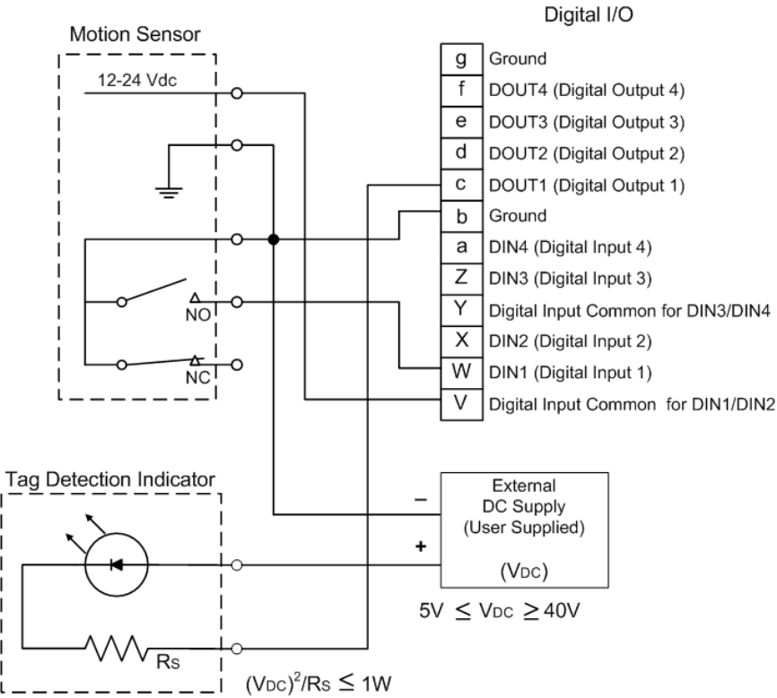
1
2
3
4
5
6
7
8
88
8
9
Configuring Digital I/Os
Configuring Digital I/OsConfiguring Digital I/Os
Configuring Digital I/Os
3M Toll RFID Reader 6204
3M Toll RFID Reader 62043M Toll RFID Reader 6204
3M Toll RFID Reader 6204
User’s Guide
User’s GuideUser’s Guide
User’s Guide
87
8787
87
8.6. Digital I/O Hardware Connection
Digital I/O Hardware ConnectionDigital I/O Hardware Connection
Digital I/O Hardware Connection
Figure 5 shows a typical sensor/indicator connection to the digital I/Os.
Figure 5 Example Motion Detector and Indicator connected to the Digital I/O

1
2
3
4
5
6
7
8
9
99
9
Specifications
SpecificationsSpecifications
Specifications
88
8888
88
3M Toll RFID Reader 6204
3M Toll RFID Reader 62043M Toll RFID Reader 6204
3M Toll RFID Reader 6204
User’s Guide
User’s GuideUser’s Guide
User’s Guide
9 Specifications
9.1.1. Reader Specifications
Reader SpecificationsReader Specifications
Reader Specifications
(General)
(General)(General)
(General)
Frequency
FrequencyFrequency
Frequency
865 – 868 MHz (ETSI)
902 – 928 MHz (FCC Part 15)
902 – 904 MHz (FCC Part 90 Low Band)
911 – 921 MHz (FCC Part 90 Dense)
RF Power
RF PowerRF Power
RF Power
20 mW – 560 mW conducted (13 – 27.5 dBm) (ETSI)
20 mW – 1 W conducted (13 – 30 dBm) (FCC Part 15)
20 mW – 2 W conducted (13 – 33 dBm) (FCC Part 90)
Power
Power Power
Power
Consumption
ConsumptionConsumption
Consumption
10 W (max while idle)
22 W (max at 33 dBm conducted output power, FCC Part 90)
Connections
ConnectionsConnections
Connections
RS-232, Digital I/O, Ethernet LAN
Input Voltage
Input VoltageInput Voltage
Input Voltage
24 VDC±5% at input of 3M supplied cable, 36 W
Input Current
Input CurrentInput Current
Input Current
1.5A maximum at 24 Vdc
Dimensions
DimensionsDimensions
Dimensions
16.5 x 13.0 x 3.4 in (419 x 330 x 86 mm)
Weight
WeightWeight
Weight
5.0 kg (11 lbs)
NOTICE
NOTICENOTICE
NOTICE:
::
:
If DC power is disconnected from the reader, wait a minimum of 30 seconds before
reapplying power.
NOTICE
NOTICENOTICE
NOTICE:
::
:
The 3M supplied power cable is only rated at 24V ±5%. Input power less than 24V ±5% while
using 3M supplied cables may result in cable and/or reader damage.

1
2
3
4
5 6
7
8
9
99
9
Specifications
SpecificationsSpecifications
Specifications
3M Toll RFID Reader 6204
3M Toll RFID Reader 62043M Toll RFID Reader 6204
3M Toll RFID Reader 6204
User’s Guide
User’s GuideUser’s Guide
User’s Guide
89
8989
89
Figure 6 Typical Power Consumption versus Conducted Output Power at 910 MHz
9.1.2. Environmental Specifications
Environmental SpecificationsEnvironmental Specifications
Environmental Specifications
Operating Temperature
Operating TemperatureOperating Temperature
Operating Temperature
-40 °F to 131 °F (-40 °C to 55 °C)
Storage Temperature
Storage TemperatureStorage Temperature
Storage Temperature
-40 °F to 185 °F (-40 °C to 85 °C)
Maximum Shock
Maximum ShockMaximum Shock
Maximum Shock
1 foot (0.3 meter) drop to any corner
Relative Humidity
Relative HumidityRelative Humidity
Relative Humidity
95 %, non-condensing
Int’l Protection Rating
Int’l Protection RatingInt’l Protection Rating
Int’l Protection Rating
IP66
9.1.3. AC/DC Power Adapter
AC/DC Power AdapterAC/DC Power Adapter
AC/DC Power Adapter
Specifications
SpecificationsSpecifications
Specifications
Model
ModelModel
Model
Lambda DSP100-24
Input Voltage
Input VoltageInput Voltage
Input Voltage
90 – 264 Vac,
Input Frequency
Input FrequencyInput Frequency
Input Frequency
47 to 63 Hz
Power
PowerPower
Power
100.8 W
Holdup Time
Holdup TimeHoldup Time
Holdup Time
10 ms (115 Vac)
Output Voltage
Output VoltageOutput Voltage
Output Voltage
24 VDC
Output Current
Output CurrentOutput Current
Output Current
4.2 A
Active Mode DC Current Draw vs Transmitted Power
0.4
0.5
0.6
0.7
0.8
0.9
1
10 15 20 25 30 35
Transm itted Power (dBm )
DC Current draw (A)
+60 degC
+25 degC
-20 degC

1
2
3
4
5
6
7
8
9
99
9
Specifications
SpecificationsSpecifications
Specifications
90
9090
90
3M Toll RFID Reader 6204
3M Toll RFID Reader 62043M Toll RFID Reader 6204
3M Toll RFID Reader 6204
User’s Guide
User’s GuideUser’s Guide
User’s Guide
9.1.4. RS
RSRS
RS-
--
-232 Specifications
232 Specifications232 Specifications
232 Specifications
Baud rate
Baud rateBaud rate
Baud rate
1200 - 115200 (Default = 115200)
Parity
ParityParity
Parity
None
Data bits
Data bitsData bits
Data bits
8
Stop bits
Stop bitsStop bits
Stop bits
1
Signals
SignalsSignals
Signals
Refer to Section
9.1.8
for cable pin out.
9.1.5. Digital Input/Output Specifications
Digital Input/Output SpecificationsDigital Input/Output Specifications
Digital Input/Output Specifications
Input
InputInput
Input
5 to 24 Vdc, 1 to 5 mA, Optically Isolated
Output
OutputOutput
Output
Open Collector (3 to 40 V, 100 mA Max)
Signals
SignalsSignals
Signals
Refer to Section
9
.1.8
for cable pin out.
9.1.6. Ethernet LAN Specifications
Ethernet LAN SpecificationsEthernet LAN Specifications
Ethernet LAN Specifications
Ethernet
EthernetEthernet
Ethernet
10/100 BaseT
Signals
SignalsSignals
Signals
Refer to Section
9.1.8
for cable pin out.

1
2
3
4
5 6
7
8
9
99
9
Specifications
SpecificationsSpecifications
Specifications
3M Toll RFID Reader 6204
3M Toll RFID Reader 62043M Toll RFID Reader 6204
3M Toll RFID Reader 6204
User’s Guide
User’s GuideUser’s Guide
User’s Guide
91
9191
91
9.1.7. 3M Toll RFID Reader
3M Toll RFID Reader3M Toll RFID Reader
3M Toll RFID Reader
6204
62046204
6204
Antenna Specifications
Antenna SpecificationsAntenna Specifications
Antenna Specifications
Please refer to the 3M Antenna Application Guide for detailed specifications
and application information for 3M Toll RFID Reader 6204 antennas.
3M SKU Number
3M SKU Number3M SKU Number
3M SKU Number
78
7878
78-
--
-0060
00600060
0060-
--
-1044
10441044
1044-
--
-7
77
7
78
7878
78-
--
-0060
00600060
0060-
--
-1045
10451045
1045-
--
-4
44
4
Previous Part Number
Previous Part NumberPrevious Part Number
Previous Part Number
ANTENNA-013 ANTENNA-018-E
Frequency range
Frequency rangeFrequency range
Frequency range
902–928 MHz 902–928 MHz
Antenna type
Antenna typeAntenna type
Antenna type
Patch Patch
Impedance
ImpedanceImpedance
Impedance
50 , nominal 50 , nominal
Gain
GainGain
Gain
13 dBi 9.0 dBic (min)
10 dBic (max)
Beam width (
Beam width (Beam width (
Beam width (-
--
-3 dB)
3 dB)3 dB)
3 dB)
42°, nominal 63°, typical
Polarization
PolarizationPolarization
Polarization
Linear RH circular
F/B ratio
F/B ratioF/B ratio
F/B ratio
-24 dB, typical -18 dB, maximum
-20 dB, typical
Side lobes level
Side lobes levelSide lobes level
Side lobes level
-19 dB, typical -16 dB, typical @ 90°
Power input
Power inputPower input
Power input
37 dBm (5 W) 38 dBm (6 W)
Return loss
Return lossReturn loss
Return loss
-12 dB, minimum -14 dB, minimum
Connector type
Connector typeConnector type
Connector type
N type Female (Jack) N type Female (Jack)
3M SKU Number
3M SKU Number3M SKU Number
3M SKU Number
78
7878
78-
--
-0060
00600060
0060-
--
-1047
10471047
1047-
--
-0
00
0
78
7878
78-
--
-0060
00600060
0060-
--
-1048
10481048
1048-
--
-8
88
8
Previous Part Number
Previous Part NumberPrevious Part Number
Previous Part Number
ANTENNA-020 ANTENNA-021
Frequency range
Frequency rangeFrequency range
Frequency range
865 - 956 MHz 902–928 MHz
Antenna type
Antenna typeAntenna type
Antenna type
Patch Patch
Impedance
ImpedanceImpedance
Impedance
50 , nominal 50 , nominal
Gain
GainGain
Gain
7.5 dBi 13 dBi
Beam width (
Beam width (Beam width (
Beam width (-
--
-3 dB)
3 dB)3 dB)
3 dB)
70°, nominal 36°, nominal
Polarization
PolarizationPolarization
Polarization
RH Circular Linear
F/B ratio
F/B ratioF/B ratio
F/B ratio
-20 dB, typical -20 dB, typical
Side lobes level
Side lobes levelSide lobes level
Side lobes level
-14 dB, typical
Power input
Power inputPower input
Power input
38 dBm (6 W) 37 dBm (5 W)
Return loss
Return lossReturn loss
Return loss
-20.8, typical -12 dB, maximum
Connector type
Connector typeConnector type
Connector type
N type Female (Jack) N type Female (Jack)

1
2
3
4
5
6
7
8
9
99
9
Specifications
SpecificationsSpecifications
Specifications
92
9292
92
3M Toll RFID Reader 6204
3M Toll RFID Reader 62043M Toll RFID Reader 6204
3M Toll RFID Reader 6204
User’s Guide
User’s GuideUser’s Guide
User’s Guide
3M SKU Number
3M SKU Number3M SKU Number
3M SKU Number
78
7878
78-
--
-0060
00600060
0060-
--
-1051
10511051
1051-
--
-2
22
2
78
7878
78-
--
-0060
00600060
0060-
--
-1053
10531053
1053-
--
-8
88
8
Previous Part Number
Previous Part NumberPrevious Part Number
Previous Part Number
ANTENNA-023 ANTENNA-024
Frequency range
Frequency rangeFrequency range
Frequency range
902–928 MHz 902–928 MHz
Antenna type
Antenna typeAntenna type
Antenna type
Multi-element Patch Multi-element Patch
Impedance
ImpedanceImpedance
Impedance
50 , nominal 50 , nominal
Gain
GainGain
Gain
15 dBi 15 dBi
Beam width (
Beam width (Beam width (
Beam width (-
--
-3 dB)
3 dB)3 dB)
3 dB)
22°, nominal 30°, nominal
Polarization
PolarizationPolarization
Polarization
Linear Linear
F/B ratio
F/B ratioF/B ratio
F/B ratio
-36 dB, typical -36 dB, typical
Side lobes level
Side lobes levelSide lobes level
Side lobes level
-18 dB, typical -18 dB, typical
Power input
Power inputPower input
Power input
37 dBm (5 W) 37 dBm (5 W)
Return loss
Return lossReturn loss
Return loss
-12 dB, minimum -12 dB, minimum
Connector type
Connector typeConnector type
Connector type
N type Female (Jack) N type Female (Jack)
3M SKU Number
3M SKU Number3M SKU Number
3M SKU Number
75
7575
75-
--
-0302
03020302
0302-
--
-3902
39023902
3902-
--
-6
66
6
Previous Part Number
Previous Part NumberPrevious Part Number
Previous Part Number
N/A
Frequency range
Frequency rangeFrequency range
Frequency range
902–928 MHz
Antenna
Antenna Antenna
Antenna type
typetype
type
Multi-element Patch
Impedance
ImpedanceImpedance
Impedance
50 , nominal
Gain
GainGain
Gain
14.5 dBi
Beam width (
Beam width (Beam width (
Beam width (-
--
-3 dB)
3 dB)3 dB)
3 dB)
22°, nominal
Polarization
PolarizationPolarization
Polarization
Linear Horizontal
F/B ratio
F/B ratioF/B ratio
F/B ratio
-25 dB, typical
Side lobes level
Side lobes levelSide lobes level
Side lobes level
-18 dB, typical
Power input
Power inputPower input
Power input
38 dBm (6 W)
Return loss
Return lossReturn loss
Return loss
-12 dB, minimum
Connector
ConnectorConnector
Connector
type
typetype
type
N type Female (Jack

1
2
3
4
5 6
7
8
9
99
9
Specifications
SpecificationsSpecifications
Specifications
3M Toll RFID Reader 6204
3M Toll RFID Reader 62043M Toll RFID Reader 6204
3M Toll RFID Reader 6204
User’s Guide
User’s GuideUser’s Guide
User’s Guide
93
9393
93
Site License
Site License Site License
Site License –
––
–
Customer Disclaimer
Customer DisclaimerCustomer Disclaimer
Customer Disclaimer
Customer (end user) acknowledges that a site license is required for each reader
system location. It is the customer’s responsibility to file for the site license and
submit the appropriate filing payment. 3M can assist with the completion of
forms. United States filings require completion and submission of FCC Form 601
with Schedule D and H. Canadian filings require completion and submission of
Industry Canada Forms IC2365BB and IC2430BB.
Licence d'Etat-client Avertissement
Client (utilisateur final) reconnaît que le site d'une licence est requise pour
chaque lecteur emplacement du système. Il incombe au client de déposer pour la
licence d'exploitation et soumettre le paiement du dépôt approprié. 3M peut aider
à la réalisation de formes. Unis dépôts États exigent l'achèvement et la
soumission du formulaire FCC 601 à l'annexe D et H. dépôts canadiennes exigent
l'achèvement et la soumission de Industrie Canada Formulaires IC2365BB et
IC2430BB
FCC Part 15
FCC Part 15 FCC Part 15
FCC Part 15 NOTICE
NOTICENOTICE
NOTICE:
::
:
This equipment complies with FCC Part 90 and Industry Canada.RSS-137
rules.
This device complies with FCC Part 15 and Industry Canada license exempt
RSS standard(s). Operation is subject to the following two conditions: (1) this
device may not cause interference, and (2) this device must accept any
interference, including interference that may cause undesired operation of
the device.
Cet appareil est conforme à FCC Partie15 de Industrie Canada RSS standard
exempts de licence (s). Son utilisation est soumise à Les deux conditions
suivantes: (1) cet appareil ne peut pas provoquer d’interférences et (2) cet
appareil doit accepter Toute interférence, y compris les interférences qui
peuvent causer un mauvais fonctionnement du dispositif.
Any changes or modifications not expressly approved by 3M could void the
user’s authority to operate the equipment.
FCC Part 90
FCC Part 90 FCC Part 90
FCC Part 90 NOTICE:
NOTICE:NOTICE:
NOTICE:
This equipment complies with FCC Part 90 and Industry Canada.RSS-137
rules.
Any changes or modifications not expressly approved by 3M could void the
user’s authority to operate the equipment.
The professional installer will need to calculate and verify the reader’s power
output allowable based on the antenna (gain) used and cabling (loss) effects.
This value will be used in the user’s submission of their site license
application. The maximum antenna gain plus cable effects for a given output
power can be calculated by:
44.8 dBm (ERP)
44.8 dBm (ERP) 44.8 dBm (ERP)
44.8 dBm (ERP) -
--
-
Pout
PoutPout
Pout
where Pout is the measured RF output power (dBm)
Reader output power is limited to a maximum of 2W under all conditions.
When operating at that power level, the maximum permissible antenna gain is
11.2dBd.
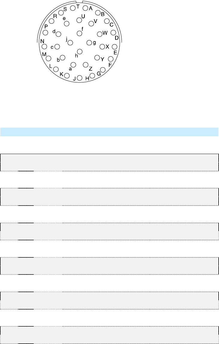
1
2
3
4
5
6
7
8
9
99
9
Specifications
SpecificationsSpecifications
Specifications
94
9494
94
3M Toll RFID Reader 6204
3M Toll RFID Reader 62043M Toll RFID Reader 6204
3M Toll RFID Reader 6204
User’s Guide
User’s GuideUser’s Guide
User’s Guide
9.1.8. Bulkhead Connector/Interface Cable Pinout
Bulkhead Connector/Interface Cable PinoutBulkhead Connector/Interface Cable Pinout
Bulkhead Connector/Interface Cable Pinout
Note:
Note:Note:
Note: Drawing is for cable socket on reader.
Pair
Pin
Color Pin Name Function
1 A Black Tx+ Ethernet
B Green Tx- Ethernet
2 C Black Rx+ Ethernet
D Orange Rx- Ethernet
3 E Blue VC2+ Ethernet
F Black VC2- Ethernet
4 G Black VC2+ Ethernet
H Brown VC2- Ethernet
5 J Black RS-232 TXD (to WIM RXD) Serial or WIM Port
K Red RS-232 RXD (to WIM TXD) Serial or WIM Port
6 L Black DTR (Short to Pin N DSR) Serial or WIM Port
M White RS-232 GND (to WIM SGND) Serial or WIM Port
7 N Black DSR (Short to Pin L DTR) Serial or WIM Port
P Yellow RS-232 CTS (to WIM RTS) Serial or WIM Port
8 R Red RS-232 RTS (to WIM CTS) Serial or WIM Port
S White No Connect Not Applicable
9 T Red +24 VDC Power
U Green 24 VDC GND Ground
10 V Red DIN Ref 1 To (+5 to +24)VRef Digital Input Common
W Blue DIN1 Digital Input 1
11 X Red DIN2 Digital Input 2
Y Yellow DIN Ref 2 To (+5 to +24)VRef Digital Input Common
12 Z Red DIN3 Digital Input 3
a Brown DIN4 Digital Input 4
13 b Red GND Ground (Reader)
1
2
3
4
5 6
7
8
9
99
9
Specifications
SpecificationsSpecifications
Specifications
3M Toll RFID Reader 6204
3M Toll RFID Reader 62043M Toll RFID Reader 6204
3M Toll RFID Reader 6204
User’s Guide
User’s GuideUser’s Guide
User’s Guide
95
9595
95
Pair
Pin
Color Pin Name Function
c Orange DOUT1 Digital Output 1
14 d Green DOUT2 Digital Output 2
e White DOUT3 Digital Output 3
15 f Green DOUT4 Digital Output 4
g Blue GND Ground (Reader)
16 h Yellow +24 VDC Heater Power
j Green 24 VDC GND Heater Ground
NOTICE
NOTICENOTICE
NOTICE:
::
:
If DC power is disconnected from the reader, wait a minimum of 30 seconds before
reapplying power.

1
2
3
4
5
6
7
8
9
Appendix A
Appendix A Appendix A
Appendix A –
––
–
Error Handling
Error HandlingError Handling
Error Handling
96
9696
96
3M Toll RFID Reader 6204
3M Toll RFID Reader 62043M Toll RFID Reader 6204
3M Toll RFID Reader 6204
User’s Guide
User’s GuideUser’s Guide
User’s Guide
A Using the Wiegand Interface
A.1. Overview
OverviewOverview
Overview
The 3M Wiegand Interface Module (WIM)
is a serial (RS-232) to 4-channel
Wiegand module designed to interface
with the 6204 reader. Currently, 2
Wiegand channels are used,
corresponding to the 2 antennas
available on the 6204. Channel 1 is
associated with the internal antenna.
Channel 2 is associated with the
External antenna.
Channels 3 and 4 can be configured to
act as open-collector, digital pulse outputs under software control. This
requires an additional custom script file to define the output function.
Contact your local 3M Representative for further information.
A.2. Wiegand Protocol
Wiegand ProtocolWiegand Protocol
Wiegand Protocol
The Wiegand communication protocol is a 3-wire communications scheme
comprising:
Data One line
Data Zero line
Ground line
These three lines constitute a Wiegand Channel.
Data is transmitted in a serial manner over these lines by pulsing the Data
One line low for a logic 1, and pulsing the Data Zero line low for a logic 0.
Two parameters define the behavior of bit-wise transmission:
Pulse Width Time (Tpw) is the duration of the pulse.
Pulse Interval Time (Tpi) is the interval between the end of a pulse and
the start of the next pulse.
Based on this, the total bit time is Tpw + Tpi.

1
2
3
4
5
6
7
8
9
Appendix A
Appendix A Appendix A
Appendix A –
––
–
Error Handling
Error HandlingError Handling
Error Handling
3M Toll RFID Reader 6204
3M Toll RFID Reader 62043M Toll RFID Reader 6204
3M Toll RFID Reader 6204
User’s Guide
User’s GuideUser’s Guide
User’s Guide
97
9797
97
A Wiegand frame consists of a string of bits transmitted in the Wiegand
format. Typically, this is 26 bits (including two parity bits). Following the
transmission of a Wiegand frame, a hold-off time (Thold) is asserted where
the Wiegand interface will not transmit. This mechanism is used to separate
adjacent Wiegand frames.
The unit, by default, outputs a 26-bit Wiegand frame (24 data bits , 2 parity
bits). Data lengths of up-to 128 bits can be accommodated. The current
default values for the Wiegand are as follows:
Parameter
ParameterParameter
Parameter
Value
ValueValue
Value
TPW Pulse Width Time 50 µs
TPI Pulse Interval Time 2000 µs
Inter Frame Message Delay Time 250 ms
Data bits 24
Parity Standard
Bit format MSB first
In some installations, Wiegand equipment may report only a single
transaction when multiple tags are read simultaneously. In this case, the
Wiegand equipment may require a larger delay between consecutive
Wiegand data frames (up to 1.5 seconds).
To increase the delay, set com.wiegand.X.physical.thold, where X
is the Wiegand output number, to the desired interframe time in ms (i.e.
1500 for 1.5 seconds).
For more information, refer to the AC-01 Wiegand Specification: “Access
Control Standard Protocol For The 26-Bit Wiegand Reader Interface”.
A.3. Wiegand Applications
Wiegand ApplicationsWiegand Applications
Wiegand Applications
Many access control panels incorporate a Wiegand Interface, and in many
applications a host reader will communicate with an access control panel
via the Wiegand Interface. Many Wiegand-enabled panels are configured to
receive Facility Code information and Serial Number information in Wiegand
format.
In an RFID-based access control system, the Facility Code and Serial
Number may be embedded into a data string known as a Translated ID. In
some applications, an actual tag ID may be mapped to a Translated ID via
some form of look-up table.
This 6204 Wiegand application primarily uses secure tags for
authentication. The reader will read such tags and derive a Translated ID
from the tag. This Translated ID is then sent to the Wiegand Interface
Module (WIM) for transmission over a Wiegand Interface to a Wiegand
panel. However, a translation table facility is incorporated for managing
standard legacy tags.
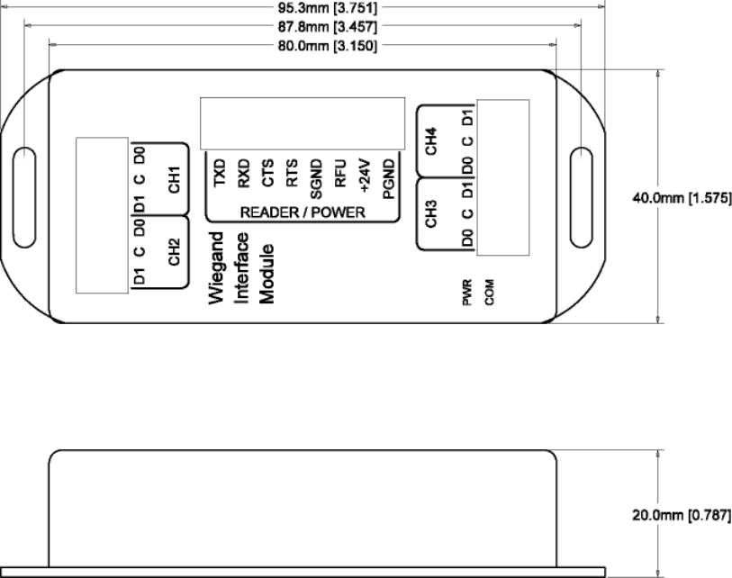
1
2
3
4
5
6
7
8
9
Appendix A
Appendix A Appendix A
Appendix A –
––
–
Error Handling
Error HandlingError Handling
Error Handling
98
9898
98
3M Toll RFID Reader 6204
3M Toll RFID Reader 62043M Toll RFID Reader 6204
3M Toll RFID Reader 6204
User’s Guide
User’s GuideUser’s Guide
User’s Guide
A.4. Mechanical Installation
Mechanical InstallationMechanical Installation
Mechanical Installation
The WIM is housed in a plastic enclosure and should be located in your
control panel. Mount the module in a ventilated area on a flat panel and
ensure that the module is protected from water and moisture ingress, and
is not mounted directly above a heat source.
Secure the module in place with two #8 (M4) flat-head type screws. Figure 7
shows the location of the mounting flanges.
Figure 7 Wiegand Interface Mounting Flanges
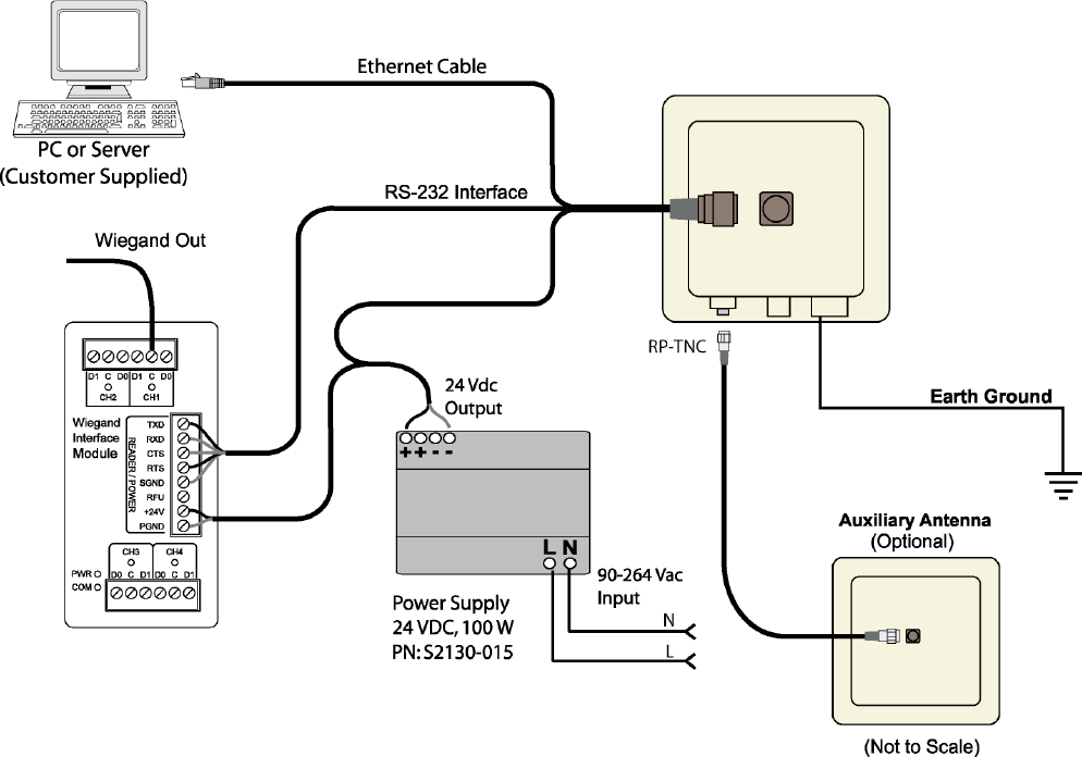
1
2
3
4
5
6
7
8
9
Appendix A
Appendix A Appendix A
Appendix A –
––
–
Error Handling
Error HandlingError Handling
Error Handling
3M Toll RFID Reader 6204
3M Toll RFID Reader 62043M Toll RFID Reader 6204
3M Toll RFID Reader 6204
User’s Guide
User’s GuideUser’s Guide
User’s Guide
99
9999
99
A.5. Electrical Installation
Electrical InstallationElectrical Installation
Electrical Installation
Power for the WIM is supplied by the 24 VDC 6204 reader power supply.
The 6204 serial port is used to communicate with the WIM and is therefore
not available for standard serial communications. Connections to the WIM
are made via pluggable screw terminal blocks.
Figure 8 3M Toll RFID Reader 6204 Electrical Connections (Wiegand Interface Module)
Refer to Figure 9 for actual Wiegand Module power and RS-232 wiring.
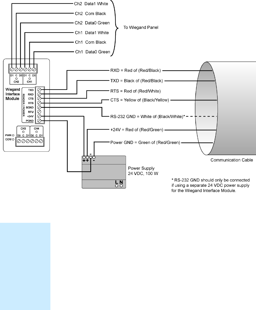
1
2
3
4
5
6
7
8
9
Appendix A
Appendix A Appendix A
Appendix A –
––
–
Error Handling
Error HandlingError Handling
Error Handling
100
100100
100
3M Toll RFID Reader 6204
3M Toll RFID Reader 62043M Toll RFID Reader 6204
3M Toll RFID Reader 6204
User’s Guide
User’s GuideUser’s Guide
User’s Guide
Figure 9 Wiegand Interface Module Electrical Connections
A.5.1. Connect the Serial Port
To connect the serial port, perform the following:
1
11
1 Terminate the reader umbilical cable using a suitable cable gland or
equivalent method.
2
22
2 Identify the serial interface wires and terminate these five wires on the
READER/POWER connector.
3
33
3 Use care when performing the termination to avoid Pin 3 (RFU) on this
connector.
Disconnecting WIM
Disconnecting WIM Disconnecting WIM
Disconnecting WIM
from Serial Port
from Serial Portfrom Serial Port
from Serial Port
In the event you
disconnect the WIM
module from the
serial port, you need
to restart the console
service for the reader
command line
interface (cli).
See “
““
“Disconnecting
Disconnecting Disconnecting
Disconnecting
the Wiegand
the Wiegand the Wiegand
the Wiegand
Interface Module
Interface ModuleInterface Module
Interface Module”
””
”
later in the is section.
1
2
3
4
5
6
7
8
9
Appendix A
Appendix A Appendix A
Appendix A –
––
–
Error Handling
Error HandlingError Handling
Error Handling
3M Toll RFID Reader 6204
3M Toll RFID Reader 62043M Toll RFID Reader 6204
3M Toll RFID Reader 6204
User’s Guide
User’s GuideUser’s Guide
User’s Guide
101
101101
101
A.5.2. Connect the Wiegand Outputs
Optically-isolated open-collector outputs are provided to meet the
requirements of the AC01 Wiegand specification. These are protected by 5V
transient voltage-suppression diodes.
To connect the Wiegand outputs, perform the following:
1
11
1 When using the single Internal antenna of the 6204, connect CH1 (3
wires) of the WIM to the Wiegand panel.
2
22
2 If using the External antenna, connect CH2 (3 wires) of the WIM to the
Wiegand panel.
3
33
3 Refer to Figure 9 for the standard Wiegand color code as defined in the
AC-01 Wiegand specification.
A.5.3. Connect the 24V Power
To connect 24V power, perform the following:
1
11
1 Using the black and red power harness supplied, connect one end of
the black wire to Terminal 1 (PGND).
2
22
2 Connect one end of the red wire to Terminal 2 (+24V) of the
READER/POWER connector.
3
33
3 Connect the remaining end of the red wire to the + output terminal.
4
44
4 Connect the remaining end of the black wire to the – output terminal of
the PSU
5
55
5 Verify the connections.
A.5.4. Initial Testing
Initial testing is optional, but recommended. The purpose is to verify that
the 24V PSU and Wiegand module power supply are operating correctly.
Perform the following:
1
11
1 Ensure that the reader is disconnected from the umbilical cable by
unlocking and removing the connector at the reader end.
2
22
2 Apply AC power to the PSU Module.
3
33
3 Using a Digital Multimeter (DMM) confirm that the output of the PSU
lies in the range 21.6 to 26.4 VDC
4
44
4 Check that the PWR LED on the module is illuminated.
5
55
5 Using the DMM, measure the DC voltage between PGND and RFU on
the READER/POWER connector. For correct operation, this should be
between 4.75 and 5.25 VDC.
6
66
6 Disconnect the PSU and reconnect the umbilical cord to the reader.
1
2
3
4
5
6
7
8
9
Appendix A
Appendix A Appendix A
Appendix A –
––
–
Error Handling
Error HandlingError Handling
Error Handling
102
102102
102
3M Toll RFID Reader 6204
3M Toll RFID Reader 62043M Toll RFID Reader 6204
3M Toll RFID Reader 6204
User’s Guide
User’s GuideUser’s Guide
User’s Guide
A.6. Disconnecting the Wiegand Interface Module
Disconnecting the Wiegand Interface ModuleDisconnecting the Wiegand Interface Module
Disconnecting the Wiegand Interface Module
In the event you wish to disconnect the WIM, perform the following:
1
11
1 Remove AC power from the PSU.
2
22
2 Disconnect the serial cable from the reader.
3
33
3 Restart the console service for the reader command line interface by
sending the following command to the reader:
com.serial.console(program=cli)
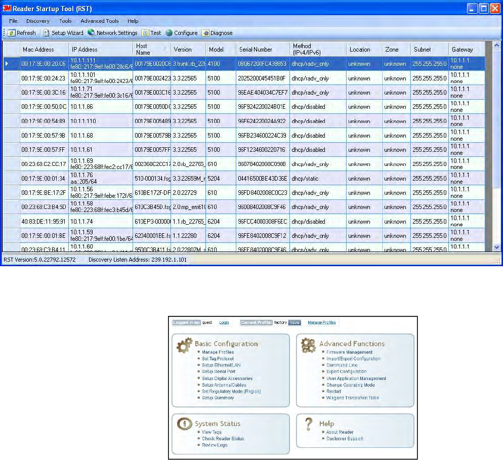
1
2
3
4
5
6
7
8
9
Appendix A
Appendix A Appendix A
Appendix A –
––
–
Error Handling
Error HandlingError Handling
Error Handling
3M Toll RFID Reader 6204
3M Toll RFID Reader 62043M Toll RFID Reader 6204
3M Toll RFID Reader 6204
User’s Guide
User’s GuideUser’s Guide
User’s Guide
103
103103
103
A.7. Using RCT to Configure the Wiegand Interface Module
Using RCT to Configure the Wiegand Interface ModuleUsing RCT to Configure the Wiegand Interface Module
Using RCT to Configure the Wiegand Interface Module
You can use the embedded Reader Configuration Tool to configure the WIM
parameters. Perform the following:
Open RST
Open RSTOpen RST
Open RST
1
11
1 From your Windows desktop, select:
Start→Programs→3M→Reader Startup Tool (RST)
2
22
2 Select a specific reader and press Configure.
3
33
3 The Reader Configuration Tool (RCT) is displayed.
4
44
4 Press Login and log into the reader as admin. The initial password is
readeradmin.
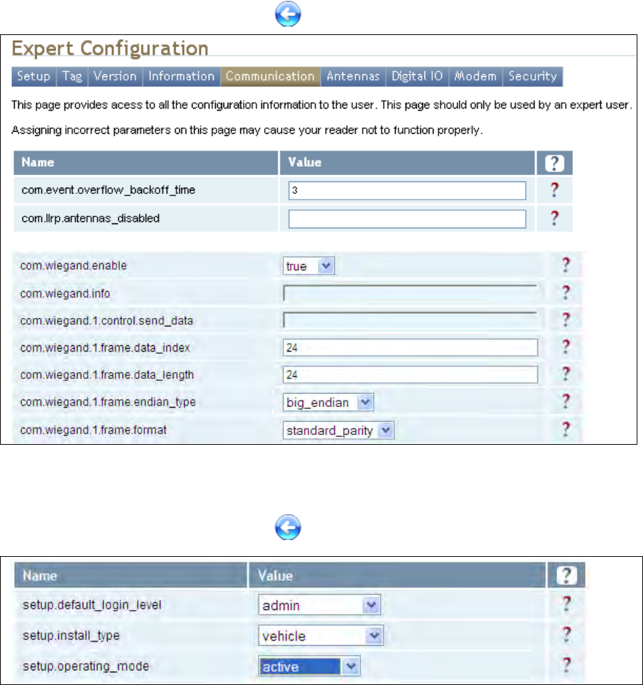
1
2
3
4
5
6
7
8
9
Appendix A
Appendix A Appendix A
Appendix A –
––
–
Error Handling
Error HandlingError Handling
Error Handling
104
104104
104
3M Toll RFID Reader 6204
3M Toll RFID Reader 62043M Toll RFID Reader 6204
3M Toll RFID Reader 6204
User’s Guide
User’s GuideUser’s Guide
User’s Guide
5
55
5 Select Advanced Functions → Expert Configuration.
6
66
6 Select the Communication tab.
7
77
7 Set com.wiegand.enable to true and press Submit.
8
88
8 Press the Back key to return to Expert Configuration screen.
9
99
9 Select the Setup tab.
10
1010
10 Set setup.operating_mode to active and press Submit.
11
1111
11 Press the Back key to return to Expert Configuration screen.
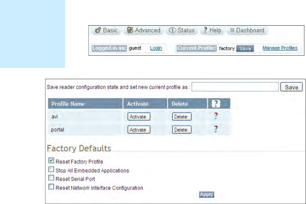
1
2
3
4
5
6
7
8
9
Appendix A
Appendix A Appendix A
Appendix A –
––
–
Error Handling
Error HandlingError Handling
Error Handling
3M Toll RFID Reader 6204
3M Toll RFID Reader 62043M Toll RFID Reader 6204
3M Toll RFID Reader 6204
User’s Guide
User’s GuideUser’s Guide
User’s Guide
105
105105
105
12
1212
12 Once setup is complete, save your settings in a Profile.
13
1313
13 In the configuration header, press Manage Profiles.
14
1414
14 The profile management page is displayed
15
1515
15 Enter a profile name in the box and press Save.
16
1616
16 Your reader configuration will be saved under this profile name and can
be quickly reloaded if the reader reboots or you lose your reader
configuration.
17
1717
17 To load a profile, press the Activate button next to the Profile Name.
Save
Save Save
Save
Reader Setup
Reader SetupReader Setup
Reader Setup
Save reader setup
information as a
profile. If you need to
reboot or power down
a reader, the reader
setup can be quickly
reloaded by loading
the profile.
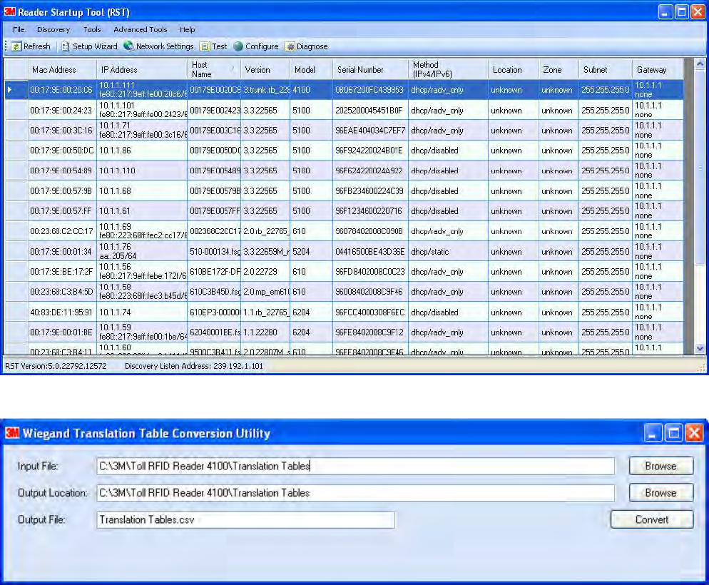
1
2
3
4
5
6
7
8
9
Appendix A
Appendix A Appendix A
Appendix A –
––
–
Error Handling
Error HandlingError Handling
Error Handling
106
106106
106
3M Toll RFID Reader 6204
3M Toll RFID Reader 62043M Toll RFID Reader 6204
3M Toll RFID Reader 6204
User’s Guide
User’s GuideUser’s Guide
User’s Guide
A.8. Converting
Converting Converting
Converting Translation Tables for use with
Translation Tables for use with Translation Tables for use with
Translation Tables for use with 6204
62046204
6204
If you have translation tables, such as those developed for Sirit IDentity MaX
readers, these tables can be converted for use with the 3M Toll RFID
Reader 6204 and Wiegand Interface Module.
For a Single Translation Table
For a Single Translation TableFor a Single Translation Table
For a Single Translation Table
1
11
1 From your Windows desktop, select:
Start→Programs→3M→Reader Startup Tool (RST)
2
22
2 Press the WTC button under Advanced Tools.
3
33
3 Enter the location and name of your input file, output file location, and
output file name.
4
44
4 Press Convert.
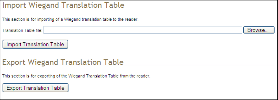
1
2
3
4
5
6
7
8
9
Appendix A
Appendix A Appendix A
Appendix A –
––
–
Error Handling
Error HandlingError Handling
Error Handling
3M Toll RFID Reader 6204
3M Toll RFID Reader 62043M Toll RFID Reader 6204
3M Toll RFID Reader 6204
User’s Guide
User’s GuideUser’s Guide
User’s Guide
107
107107
107
For Multiple Translation Tables
For Multiple Translation TablesFor Multiple Translation Tables
For Multiple Translation Tables
1
11
1 If you have multiple translation tables to convert, perform the previous
procedure for each table.
2
22
2 Create a new document using a text editor such as Notepad. This will
be the main file used to build the combined translation table.
3
33
3 Start another session of the text editor (such as Notepad) to open one
of the converted translation tables.
4
44
4 Copy the contents and paste them into the main file. (The converted
translation tables have a .csv extension. Do not open these by double-
clicking, as this will invoke Excel).
5
55
5 Repeat Step 3 for all converted tables.
6
66
6 Use care to not replicate the same information multiple times. Edit the
main file if necessary to eliminate duplications.
7
77
7 Save the main file, giving it a .csv extension.
A.9. Importing/Exporting a Translation Table
Importing/Exporting a Translation TableImporting/Exporting a Translation Table
Importing/Exporting a Translation Table
To load or import a translation table, perform the following:
1
11
1 Under the Advanced Functions, select Import/Export Configuration.
2
22
2 Under Import Wiegand Translation Table, press Browse and navigate
to the location of your translaitons tables.
3
33
3 Select the translation table file name and press Import Translation
Table.
4
44
4 To export the translation table, press Export Translation Table.
5
55
5 Save the file as needed.

1
2
3
4
5
6
7
8
9
Appendix A
Appendix A Appendix A
Appendix A –
––
–
Error Handling
Error HandlingError Handling
Error Handling
108
108108
108
3M Toll RFID Reader 6204
3M Toll RFID Reader 62043M Toll RFID Reader 6204
3M Toll RFID Reader 6204
User’s Guide
User’s GuideUser’s Guide
User’s Guide
A.10. Programming the Wiegand Interf
Programming the Wiegand InterfProgramming the Wiegand Interf
Programming the Wiegand Interface
aceace
ace
The WIM may be configured in hardware to contain two or four Wiegand
channels. Each channel can be individually configured and controlled.
In the following variable and function descriptions <n> will refer to a generic
Wiegand channel. Valid values include 1,2 (Wiegand channels 1, 2) for all
systems and 3,4 (Wiegand channels 3, 4) for four channel modules. (See
Module Type 0x14 in the com.wiegand.info variable description). A
channel value falling out of range should generate an error.
For this system, Wiegand channel 1 is associated with the Internal antenna
and Wiegand channel 2 is associated with the External antenna.
com.wiegand.dealer_code_list
This variable is used to configure a string of dealer codes.
A Dealer Code List can be configured with one or more Dealer Codes, each
separated by a "space". Authenticated secure tags containing a Dealer Code
which matches a value in the Dealer Code List will be forwarded to the
Wiegand interface. Authenticated secure tags containing a Dealer Code that
does not match a value in the Dealer Code List will be blocked. Dealer Code
filtering does not apply to legacy tags. Dealer Code filtering can be disabled
by specifying a blank Dealer Code List.
Type
TypeType
Type
var
Permissions
PermissionsPermissions
Permissions
guest=r,admin=rw
Data Type
Data TypeData Type
Data Type
string
Default
DefaultDefault
Default
""
com.wiegand.dealer_code_list
This variable provides a space-separated list of dealer codes used by
Wiegand application to filter out tags. Empty list means no dealer code is
used.
Type var
Permissions guest=r,admin=rw
Data Type string
Default ""

1
2
3
4
5
6
7
8
9
Appendix A
Appendix A Appendix A
Appendix A –
––
–
Error Handling
Error HandlingError Handling
Error Handling
3M Toll RFID Reader 6204
3M Toll RFID Reader 62043M Toll RFID Reader 6204
3M Toll RFID Reader 6204
User’s Guide
User’s GuideUser’s Guide
User’s Guide
109
109109
109
com.wiegand.enable
This variable enables/disables the WIM.
Type
TypeType
Type
var
Permissions
PermissionsPermissions
Permissions
guest=r,admin=rw
Data Type
Data TypeData Type
Data Type
bool
Default
DefaultDefault
Default
false
com.wiegand.events_only
If this variable is set to true, WIMApp will run and use the translation table,
but will not actually communicate with a Wiegand Interface Module over the
serial port. event.wim.report events are generated, and this is the only
output from WIMAPP.
This mode is intended to be used in order to allow WIMAPP to perform
access control functionality using the translation table as a whitelist. When
false, WIMAPP attempts to communicate with the Wiegand Interface
Module on the serial port and will not function properly if this
communication is impossible.
Type
TypeType
Type
var
Permissions
PermissionsPermissions
Permissions
guest=r,admin=rw
Data Type
Data TypeData Type
Data Type
bool
Default
DefaultDefault
Default
true
com.wiegand.export_table
Export translation table of the Wiegand module to /tmp/wim/table.
Type
TypeType
Type
function
Permissions
PermissionsPermissions
Permissions
guest=-,admin=x

1
2
3
4
5
6
7
8
9
Appendix A
Appendix A Appendix A
Appendix A –
––
–
Error Handling
Error HandlingError Handling
Error Handling
110
110110
110
3M Toll RFID Reader 6204
3M Toll RFID Reader 62043M Toll RFID Reader 6204
3M Toll RFID Reader 6204
User’s Guide
User’s GuideUser’s Guide
User’s Guide
com.wiegand.id_format
If this variable is set to HEXADECIMAL, the full wiegand ID will be displayed
as a single hexadecimal number in the wiegand_id field of tag reports. If
this variable is set to FORMATTED, the wiegand ID will be split into facility
code and serial number portions, and each field will be displayed in decimal
notation (i.e. 123-4567) in the wiegand_id field of tag report events.
Type
TypeType
Type
var
Permissions
PermissionsPermissions
Permissions
guest=r,admin=rw
Data Type
Data TypeData Type
Data Type
enum
Default
DefaultDefault
Default
FORMATTED
Enum
EnumEnum
Enum
HEXADECIMAL FORMATTED
com.wiegand.import_table
Import translation table of the Wiegand module.
Type
TypeType
Type
function
Permissions
PermissionsPermissions
Permissions
guest=-,admin=x
Parameters
ParametersParameters
Parameters
file (string)
com.wiegand.info
This variable returns a string containing information about the WIM, such as
number of channels (channels), firmware version number
(firmware_version) and serial number (serial_no).
>>> com.wiegand.info()
ok channels=4, firmware_version=0.25,
serial_no=0x1122334455667788
Type
TypeType
Type
var
Permissions
PermissionsPermissions
Permissions
guest=r,admin=rw
Data Type
Data TypeData Type
Data Type
string
Default
DefaultDefault
Default
""

1
2
3
4
5
6
7
8
9
Appendix A
Appendix A Appendix A
Appendix A –
––
–
Error Handling
Error HandlingError Handling
Error Handling
3M Toll RFID Reader 6204
3M Toll RFID Reader 62043M Toll RFID Reader 6204
3M Toll RFID Reader 6204
User’s Guide
User’s GuideUser’s Guide
User’s Guide
111
111111
111
com.wiegand.reset
This function resets the WIM.
Type
TypeType
Type
function
Permissions
PermissionsPermissions
Permissions
guest=-,admin=x
com.wiegand.retransmission_interval
This variable provides the facility for a Wiegand stream to be retransmitted
at defined periodic intervals for the time a tag resides in the RF field. This
variable defines the interval in seconds. A value of 0 disables the
retransmission mechanism.
Type
TypeType
Type
var
Permissions
PermissionsPermissions
Permissions
guest=r,admin=rw
Data Type
Data TypeData Type
Data Type
int
Default
DefaultDefault
Default
0
Min
MinMin
Min
0
Max
MaxMax
Max
300
com.wiegand.<n>.control.send_data
This variable sends data to the Wiegand interface. The data is specified in
hexadecimal form (for example, 0xXXXXXXXXXXXXXXXX) and represents a
value of up-to 8 bytes. The data will typically represent a translated ID. n = 1
to 4.
Type
TypeType
Type
var
Permissions
PermissionsPermissions
Permissions
guest=r,admin=rw
Data Type
Data TypeData Type
Data Type
string
Default
DefaultDefault
Default
""
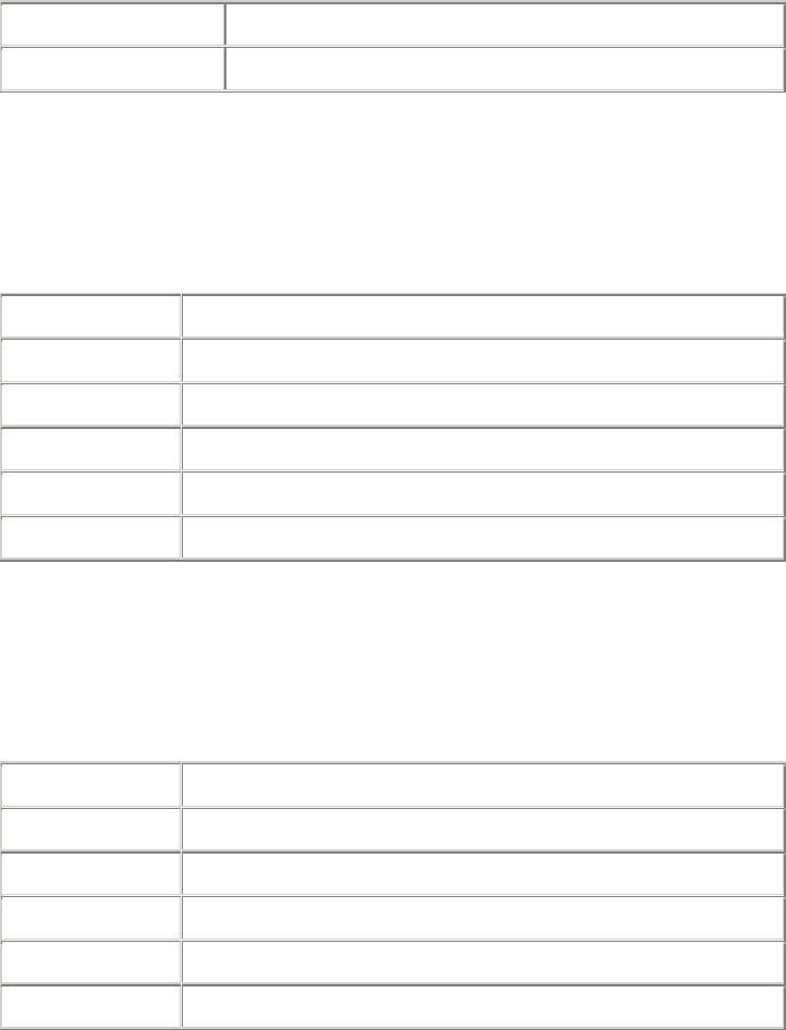
1
2
3
4
5
6
7
8
9
Appendix A
Appendix A Appendix A
Appendix A –
––
–
Error Handling
Error HandlingError Handling
Error Handling
112
112112
112
3M Toll RFID Reader 6204
3M Toll RFID Reader 62043M Toll RFID Reader 6204
3M Toll RFID Reader 6204
User’s Guide
User’s GuideUser’s Guide
User’s Guide
com.wiegand.<n>.control.send_test_pattern
Send a fixed, predetermined test pattern to the Wiegand channel.
n = 1 to 4.
Type
TypeType
Type
function
Permissions
PermissionsPermissions
Permissions
guest=-,admin=x
com.wiegand.<n>.frame.data_index
This variable sets or interrogates the data index. This is the index, in bits,
where serialization of the translated ID begins (for discarding
unused/redundant translated ID bits, for example Dealer Code). n = 1 to 4.
Type
TypeType
Type
var
Permissions
PermissionsPermissions
Permissions
guest=rw,admin=rw
Data Type
Data TypeData Type
Data Type
int
Default
DefaultDefault
Default
24
Min
MinMin
Min
0
Max
MaxMax
Max
255
com.wiegand.<n>.frame.data_length
This variable sets or interrogates the data length of the Wiegand frame. This
defines the total number of bits (excluding parity bits) of a translated ID that
will be transmitted over the Wiegand interface. n = 1 to 4.
Type
TypeType
Type
var
Permissions
PermissionsPermissions
Permissions
guest=r,admin=rw
Data Type
Data TypeData Type
Data Type
int
Default
DefaultDefault
Default
24
Min
MinMin
Min
1
Max
MaxMax
Max
112

1
2
3
4
5
6
7
8
9
Appendix A
Appendix A Appendix A
Appendix A –
––
–
Error Handling
Error HandlingError Handling
Error Handling
3M Toll RFID Reader 6204
3M Toll RFID Reader 62043M Toll RFID Reader 6204
3M Toll RFID Reader 6204
User’s Guide
User’s GuideUser’s Guide
User’s Guide
113
113113
113
com.wiegand.<n>.frame.endian_type
This variable sets or interrogates the endian type of the Wiegand output
frame. This defines whether the most-significant, or least- significant bit of
the selected portion of the translated ID will be transmitted first. n = 1 to 4.
Type
TypeType
Type
var
Permissions
PermissionsPermissions
Permissions
guest=r,admin=rw
Data Type
Data TypeData Type
Data Type
enum
Default
DefaultDefault
Default
BIG_ENDIAN
Enum
EnumEnum
Enum
BIG_ENDIAN LITTLE_ENDIAN
com.wiegand.<n>.frame.fc_length
This variable is used to set or interrogate the length of the facility code
portion of the Wiegand ID. The serial number length of the ID is implied by
the difference between com.wiegand.X.frame.data_length and the
corresponding fc_length. This field is used when the wiegand data is
presented in FORMATTED mode (see com.wiegand.id_format). n = 1 to 4.
Type
TypeType
Type
var
Permissions
PermissionsPermissions
Permissions
guest=r,admin=rw
Data Type
Data TypeData Type
Data Type
int
Default
DefaultDefault
Default
8
Min
MinMin
Min
0
Max
MaxMax
Max
112
com.wiegand.<n>.frame.format
This variable sets or interrogates the frame format of the Wiegand output.
n = 1 to 4.
Type
TypeType
Type
var
Permissions
PermissionsPermissions
Permissions
guest=r,admin=rw
Data Type
Data TypeData Type
Data Type
enum
Default
DefaultDefault
Default
STANDARD_PARITY
Enum
EnumEnum
Enum
STANDARD_PARITY REVERSE_PARITY CHECKSUM RAW_DATA

1
2
3
4
5
6
7
8
9
Appendix A
Appendix A Appendix A
Appendix A –
––
–
Error Handling
Error HandlingError Handling
Error Handling
114
114114
114
3M Toll RFID Reader 6204
3M Toll RFID Reader 62043M Toll RFID Reader 6204
3M Toll RFID Reader 6204
User’s Guide
User’s GuideUser’s Guide
User’s Guide
com.wiegand.<n>.physical.thold
This variable is used to set or to interrogate the inter-frame hold-off time
(Thold), where the inter-frame hold-off time is specified in milliseconds.
Values of 50 to 20,000 ms are valid. The default value is 250 ms. The
variable will return a value in the range 50 to 20,000 ms. n = 1 to 4.
Note that the WIM has a granularity of 50 ms and hold-off times will be
truncated to the nearest 50 ms.
Type
TypeType
Type
var
Permissions
PermissionsPermissions
Permissions
guest=r,admin=rw
Data Type
Data TypeData Type
Data Type
int
Default
DefaultDefault
Default
5
Min
MinMin
Min
50
Max
MaxMax
Max
20000
com.wiegand.<n>.physical.tpi
This variable is used to set or interrogate the pulse interval time, where the
pulse interval time is specified in microseconds. Values of 200 µs to
20,000 µs are valid. The default value is 2000 µs. The variable will return a
value in the range 200 to 20,000 µs. n = 1 to 4.
Note that the WIM has a granularity of 200 µs. Therefore,
pulse_interval_times will be truncated to the nearest 200 µs.
Type
TypeType
Type
var
Permissions
PermissionsPermissions
Permissions
guest=r,admin=rw
Data Type
Data TypeData Type
Data Type
int
Default
DefaultDefault
Default
2000
Min
MinMin
Min
200
Max
MaxMax
Max
20000
1
2
3
4
5
6
7
8
9
Appendix A
Appendix A Appendix A
Appendix A –
––
–
Error Handling
Error HandlingError Handling
Error Handling
3M Toll RFID Reader 6204
3M Toll RFID Reader 62043M Toll RFID Reader 6204
3M Toll RFID Reader 6204
User’s Guide
User’s GuideUser’s Guide
User’s Guide
115
115115
115
com.wiegand.<n>.physical.tpw
This variable is used to set or to interrogate the pulse width time (Tpw),
where the pulse width time is specified in microseconds. Values of 40 to
250 µs are valid. The default value is 50 µs. The variable will return a value
in the range 40 to 250 µs. n = 1 to 4.
Note that the WIM has a granularity of 5 µs and pulse_width_times will be
truncated to the nearest 5 µs.
Also note that these are nominal time values for 470 pull-up loads on the
Wiegand outputs. The pulse width time lengthens for higher values of pull-
ups, and shortens for lower values. This phenomenon is caused by Miller
capacitance on the loads. The 5 µs granularity on the pulse_width_time can
be used to tailor the pulse width to the required value.
Type
TypeType
Type
var
Permissions
PermissionsPermissions
Permissions
guest=r,admin=rw
Data Type
Data TypeData Type
Data Type
int
Default
DefaultDefault
Default
50
Min
MinMin
Min
40
Max
MaxMax
Max
255
error.wiegand.failure
This response indicates WIM function failed.
event.wim.report
This event is generated each time data is sent to the WIM interface. The
event returns the translated ID, timestamp, and antenna value
Type
TypeType
Type
event
Permissions
PermissionsPermissions
Permissions
guest=rw,admin=rw
Return Values
Return ValuesReturn Values
Return Values
id (int)
time (string)
text (string)

1
2
3
4
5
6
7
8
9
Appendix A
Appendix A Appendix A
Appendix A –
––
–
Error Handling
Error HandlingError Handling
Error Handling
116
116116
116
3M Toll RFID Reader 6204
3M Toll RFID Reader 62043M Toll RFID Reader 6204
3M Toll RFID Reader 6204
User’s Guide
User’s GuideUser’s Guide
User’s Guide
definitions.enum.wiegand.frame.endian_type
This variable sets wiegand module ouput frame endian type.
Type
TypeType
Type
var
Permissions
PermissionsPermissions
Permissions
guest=,admin=
Data Type
Data TypeData Type
Data Type
enum
Default
DefaultDefault
Default
BIG_ENDIAN
Enum
EnumEnum
Enum
BIG_ENDIAN LITTLE_ENDIAN
definitions.enum.wiegand.frame.format
This variable sets wiegand module ouput frame format.
Type
TypeType
Type
var
Permissions
PermissionsPermissions
Permissions
guest=,admin=
Data Type
Data TypeData Type
Data Type
enum
Default
DefaultDefault
Default
STANDARD_PARITY
Enum
EnumEnum
Enum
STANDARD_PARITY REVERSE_PARITY CHECKSUM
RAW_DATA

1
2
3
4
5
6
7
8
9
Appendix A
Appendix A Appendix A
Appendix A –
––
–
Error Handling
Error HandlingError Handling
Error Handling
3M Toll RFID Reader 6204
3M Toll RFID Reader 62043M Toll RFID Reader 6204
3M Toll RFID Reader 6204
User’s Guide
User’s GuideUser’s Guide
User’s Guide
117
117117
117
A.11. Programming the Translation Table
Programming the Translation TableProgramming the Translation Table
Programming the Translation Table
The 6204 has a translation table facility that allows a translation table to be
imported into the reader. This facility serves three primary functions:
Support the use of legacy tags.
Manage exceptions, such as the black-listing of tags.
Serve as the list of allowed (and/or black-listed) tags for a standalone
access control system (See Standalone Reader Operation Application
Note).
A.11.1. Translation Table Format
The translation table uses a comma-separated variable (csv) format and will
typically have a .csv extension. The first line of the file must contain the
version number of the file format.
Currently the file format version is 1.0. The second line of the file may
optionally contain a string FC_LEN=X,SNR_LEN=Y, where X and Y are the
facility code and serial number bit lengths respectively. If present, this line
indicates how any decimal translated IDs in the rest of the file shall be
interpreted (i.e. how many bits are represented by each field). If not
present, a facility code length of 8 bits and a serial number length of 16 bits
is assumed. Note that currently the web interface (RCT) does not generate
this optional line, so any web-entered decimal Wiegand data assumes these
default bit field lengths.
Each subsequent line of the file represents a sequence of tags and has the
following format:
[StartID],[TagType],[StartXlateID],[Entries],[Handler]<CR><LF>
where:
[StartID] is the first tag ID of a sequence of tag IDs. In most cases,
this is a hexadecimal number, preceded by 0x. If the tag protocol is
configured to display tag IDs in 6 bit ASCII format, this is the ASCII string
representing the starting tag ID. In the ASCII tag case, this is typically a
4 letter identifier followed by a 8 digit decimal number.
[TagType] is the tag protocol type. This must be one of the protocols
supported by the reader, for example, ISOC or ISOB.
[StartXlateID] is the first translated ID of a sequence of translated
IDs. The number is preceded by 0x. This value may be in hexadecimal
format (if preceded by 0x), or in decimal format with facility code and
serial number separated by a dash (i.e. "123-4567").
[Entries] is presented as a decimal number representing the
number of tags in the sequence.
Note: Maximum Number of
Note: Maximum Number of Note: Maximum Number of
Note: Maximum Number of
FC and SNR Values
FC and SNR ValuesFC and SNR Values
FC and SNR Values
When populating the
translation table, specify
only values that can be
expressed in the number of
bits used for Facility Code
(FC) and Serial Number
(SNR).
For example, if 16 bit serial
numbers are used, then
only serial numbers in the
range of 0 through 65535
should be specified in the
table.
1
2
3
4
5
6
7
8
9
Appendix A
Appendix A Appendix A
Appendix A –
––
–
Error Handling
Error HandlingError Handling
Error Handling
118
118118
118
3M Toll RFID Reader 6204
3M Toll RFID Reader 62043M Toll RFID Reader 6204
3M Toll RFID Reader 6204
User’s Guide
User’s GuideUser’s Guide
User’s Guide
[Handler] determines how tag is processed and is a decimal number
(between 0 and 255) that applies to all tags in the sequence. Where:
Bit 7: Password Authentication Indicator
1 = Password Authenticated
0 = Not Password Authenticated
Bit 6: Blacklist Indicator
1 = Blacklisted
0 = not Blacklisted
Bit 5: TID Authentication Indicator
1 = TID Authenticated
0 = Not TID Authenticated
Bit 4: RFU (0)
Bit 3: RFU (0)
Bit 2: RFU (0)
Bit 1: RFU (0)
Bit 0: Handler value
1 = Pass Translated ID to WIM
0 = Do not pass translated ID to WIM
A.11.2. Typical Handler values
1 – Legacy tag whose data is to be passed through the system to the
Wiegand interface (00000001b)
64 – Black-listed Legacy tag (01000000b).
33 – TID-Authenticated Tag whose data is to be passed through the
system to the Wiegand interface (00100001b).
96 – Black-listed TID-Authenticated tag (01100000b).
129 – Password-Authenticated Tag whose data is to be passed through
the system to the Wiegand interface (10000001b).
192 – Black-listed Password-Authenticated tag (11000000b).
A.11.3. Example Table Entry
The following is a typical translation table entry.
0x000000000000000000010000,ISOC,
0x000A0100,1000,1<CR><LF>
This entry indicates:
1000 ISOC protocol tags in the sequence
Each with a handler value of 1 (legacy tag passed through system)
Actual tag IDs range from 0x000000000000000000010000 to
0x0000000000000000000103E7
Corresponding translated IDs would range from 0x000A0100 to
0x000A04E7
1
2
3
4
5
6
7
8
9
Appendix A
Appendix A Appendix A
Appendix A –
––
–
Error Handling
Error HandlingError Handling
Error Handling
3M Toll RFID Reader 6204
3M Toll RFID Reader 62043M Toll RFID Reader 6204
3M Toll RFID Reader 6204
User’s Guide
User’s GuideUser’s Guide
User’s Guide
119
119119
119
A.12. Interaction between
Interaction between Interaction between
Interaction between Translation Table and Wiegand
Translation Table and WiegandTranslation Table and Wiegand
Translation Table and Wiegand-
--
-
Encoded Tags
Encoded TagsEncoded Tags
Encoded Tags
Some tags are encoded with Wiegand data directly on them. The 3M Toll
RFID Reader 6204 supports these direct Wiegand encoded tags of the
following format:
Secure ISOC
ISOB
ISO10374 (if supported by your model of 6204)
Flex (if supported by your model of 6204)
Because of the security features present on direct Wiegand encoded Secure
ISOC tags, they can be positively identified, and the Wiegand data encoded
on the tag is transmitted via the WIM. For each of the other protocols, some
C2 variables are used to enable the direct Wiegand feature on a protocol-
by-protocol basis:
modem.protocol.isob.control.wiegand.enabled
modem.protocol.iso10374.control.wiegand.enabled
modem.protocol.flex.control.wiegand.enabled
When these variables are set to "true", WIMapp will perform the following
actions when a tag is read:
1.
1.1.
1. The standard tag ID will be looked up in the translation table (described
above). If there is an entry matching the tag ID in the translation table,
the action specified by the translation table entry will be performed.
2.
2.2.
2. If the tag ID is not present in the translation table, and if the direct
Wiegand feature is enabled via the variables above, then the Wiegand
data encoded on the tag will be transmitted via the WIM.
Although the default values are correct for most installations, and should
not be changed without consulting 3M technical support, it is possible to
modify the areas in tag memory from which the Wiegand data is extracted
by changing the following variables:
modem.protocol.isob.control.wiegand.length
modem.protocol.isob.control.wiegand.offset
modem.protocol.iso10374.control.wiegand.length
modem.protocol.iso10374.control.wiegand.offset
modem.protocol.flex.control.wiegand.length
modem.protocol.flex.control.wiegand.offset
1
2
3
4
5
6
7
8
9
Appendix A
Appendix A Appendix A
Appendix A –
––
–
Error Handling
Error HandlingError Handling
Error Handling
120
120120
120
3M Toll RFID Reader 6204
3M Toll RFID Reader 62043M Toll RFID Reader 6204
3M Toll RFID Reader 6204
User’s Guide
User’s GuideUser’s Guide
User’s Guide
A.13. Transaction Log
Transaction LogTransaction Log
Transaction Log
A transaction log is used to record information on tag arrivals. Each entry in
the log contains the following information:-
[time] – provides the date and time of the tag arrival.
[tag_id] – ID of the tag.
[antenna] – states the antenna where the tag was read.
[handle] – 8-bit values that provide information about a tag upon its
arrival. The bit values are defined as:
Bit 7 Password Authentication
1 = Password Authenticated
0 = Not Password Authenticated
Bit 6 Blacklist Indicator
1 = Blacklisted
0 = Not Blacklisted
Bit 5 TID-Authentication
1 = TID Authenticated
0 = Not TID Authenticated
Bit 4 User Data Read Failure
1 = Failed To Read User Data
0 = User Data Read (for authenticated tag)
(or) Not Applicable (for legacy tag)
Bit 3 Dealer Code Mismatch
1 = Dealer Code Mismatch
0 = Dealer Code Match (for authenticated tag)
(or) Not Applicable (for legacy tag)
Bit 2 RFU
Bit 1 RFU
Bit 0 Wiegand Access
1 = Translated ID passed to Wiegand interface.
0 = No data passed to Wiegand interface.
[type] – tag protocol type
[translated_id] – hexadecimal value of the translated tag ID (result of
the translation table lookup).

1
2
3
4
5
6
7
8
9
Appendix A
Appendix A Appendix A
Appendix A –
––
–
Error Handling
Error HandlingError Handling
Error Handling
3M Toll RFID Reader 6204
3M Toll RFID Reader 62043M Toll RFID Reader 6204
3M Toll RFID Reader 6204
User’s Guide
User’s GuideUser’s Guide
User’s Guide
121
121121
121
A.14. Module Specifications
Module SpecificationsModule Specifications
Module Specifications
Operating Temperature Range
Operating Temperature RangeOperating Temperature Range
Operating Temperature Range
-40C to +60C
Storage Temperature Range
Storage Temperature RangeStorage Temperature Range
Storage Temperature Range
-40C to +85C
DC
DC DC
DC Power Input
Power InputPower Input
Power Input
12V-28V DC reverse polarity protected
Total Power Consumption
Total Power ConsumptionTotal Power Consumption
Total Power Consumption
<1.25W (equivalent to <60mA @ 24VDC)
RS
RSRS
RS-
--
-232 Serial Port
232 Serial Port232 Serial Port
232 Serial Port
115,200 Baud, 8 Bits, No Parity, 1 Stop Bit
Wiegand Port
Wiegand PortWiegand Port
Wiegand Port
Data Zero and Data One outputs
Configuration type 5Y (See App A of AC-01 Wiegand Specification)
Outputs Optically isolated open-collector outputs
capable of sinking 25mA
These outputs will need to be pulled up to 5V at
the inputs of the terminating Wiegand panel.
Optimum pull-up resistor values lie in the range
470 to 1k.
Tpw (Output Pulse Width) 40 s -255s in 5s increments
(with 470 pull-up resistor)
Tpi (Output Pulse Interval) 200s to 20ms in 200s steps
Hold-off time 50ms-20s in 50ms steps

1
2
3
4
5
6
7
8
9
Appendix B
Appendix B Appendix B
Appendix B –
––
–
Error Handling
Error HandlingError Handling
Error Handling
122
122122
122
3M Toll RFID Reader 6204
3M Toll RFID Reader 62043M Toll RFID Reader 6204
3M Toll RFID Reader 6204
User’s Guide
User’s GuideUser’s Guide
User’s Guide
B Error Handling
This appendix provides a listing of errors and warnings. Where applicable, a
corrective action has been provided. Errors and warnings are listed by
severity (critical, major, warning) and then alphabetically. If an issue does
not resolve itself after taking the recommended corrective action, contact
3M support.
B.1. Critical Errors
Critical ErrorsCritical Errors
Critical Errors
Critical errors are those errors that are likely to result in loss or severe
degradation of service. These errors must be addressed immediately.
Critical
Critical Critical
Critical Error
ErrorError
Error
Event
EventEvent
Event
Description
DescriptionDescription
Description
Corrective Action
Corrective ActionCorrective Action
Corrective Action
MDM_ANTENNA_ FAILURE
event.error.
antenna
Failed to set or change
antenna. Probably due to
un-terminated antenna
port.
Check condition of antennas,
connectors, and coax. Use
modem.antennas.perform_check() to
perform antenna check function to
determine if issue has been located.
MDM_CLOSED_LOOP_
POWER_CTL_FAIL
event.error.
radio
Internal RF power control
failed. May cause
inaccurate antenna power
output.
Perform reader reboot. If condition
persists, contact 3M support.
MDM_OVERTEMP_ FAULT event.error.
environmental
High temperature
measured at modem
Determine cause of excessive reader
temperature and correct.
MDM_RC_CANT_SET_
FREQUENCY
event.error.
radio
Synthesizer problem tuning
to desired frequency.
Perform reader reboot. If condition
persists, contact 3M support.
MDM_RC_NO_ ANTENNA event.error.
antenna
Failed to detect antenna.
Probably due to antenna
disconnected.
Check antenna connections, then
perform antenna check function.
MDM_SPI_NO_
RESPONSE
event.error.
communication
Modem has attempted to
communicate with a SPI
bus peripheral and
received no response.
Perform reader reboot. If condition
persists, contact 3M support.
MDM_SYNTHESIZER_
LOCK_FAIL
event.error.
radio
Synthesizer can't lock to
desired frequency.
Perform reader reboot. If condition
persists, contact 3M support.
MDM_TEMPERATURE_
SENSOR_FAIL
event.error.hw Temperature sensor
unable to detect
temperature.
Perform reader reboot. If condition
persists, contact 3M support.
READER_INIT_FAILURE event.error.sw The main processor has
failed to successfully
complete the initialization
process.
Perform reader reboot. If condition
persists, contact 3M support.
SEEPROM_UNABLE_
TO_WRITE
event.error.hw Unable to write to
SEEPROM.
Perform reader reboot. If condition
persists, contact 3M support.

1
2
3
4
5
6
7
8
9
Appendix B
Appendix B Appendix B
Appendix B –
––
–
Error Handling
Error HandlingError Handling
Error Handling
3M Toll RFID Reader 6204
3M Toll RFID Reader 62043M Toll RFID Reader 6204
3M Toll RFID Reader 6204
User’s Guide
User’s GuideUser’s Guide
User’s Guide
123
123123
123
B.2. Major Errors
Major ErrorsMajor Errors
Major Errors
Major errors are those errors that may result in loss or degradation of
service. These errors must be addressed as soon as possible.
Major
Major Major
Major Error
ErrorError
Error
Event
EventEvent
Event
Description
DescriptionDescription
Description
Corrective Action
Corrective ActionCorrective Action
Corrective Action
CHUNK_NOT_ FOUND event.error.sw Unable to find valid data in
the flash.
Perform reader reboot. If condition
persists, contact 3M support.
DATA_FORMAT_
ERROR
event.error.sw An error is detected in the
data format.
Perform reader reboot. If condition
persists, contact 3M support.
DEVICE_INIT_
FAILURE
event.error.sw Error initializing a device in
the system.
Perform reader reboot. If condition
persists, contact 3M support.
DEVICE_OPEN_
FAILURE
event.error.sw Unable to open device or
piped command.
Check memory and disk usage via
"Check Reader Status" webpage. If
"free_memory" is lower then 10 MBytes
or if filesystem:/apps or filesystem:/tmp
is higher than 90%, determine if
embedded application is improperly
using memory. If condition persists,
contact 3M support.
INDEX_OUT_OF_
BOUNDS
event.error.sw Software is indexing
beyond end of array.
If condition persists, contact 3M support.
INVALID_ ARGUMENT event.error.sw Argument of an internal
command is invalid.
If condition persists, contact 3M support.
IOP_CONMGR_
INVALID_CMDRESP_
FD
event.error.
communication
Unknown command
channel being closed.
Perform reader reboot. If condition
persists, contact 3M support.
IOP_CONMGR_
INVALID_EVENT_FD
event.error.
communication
Unknown event channel
being closed.
Perform reader reboot. If condition
persists, contact 3M support.
IOP_HB_MODEM_
NOT_RESPONDING
event.error.hw Modem not responding to
keepalives from main
processor.
If condition persists, contact 3M support.
IOP_IPRC_CRC_
ERROR
event.error.
communication
Communication from
modem processor had a
CRC error. May see at
bootup, since extra bytes
are sent from modem
processor during its boot
squence.
Usually caused by excessive processing
loading on the reader by external
entities. Determine if any external
process is continuously sending
command requests to the reader at a
high rate. If running an embedded
application, ensure that it is not
monopolizing the processor. If condition
persists, contact 3M support.
IOP_IPRC_TIMEOUT event.error.
communication
Communication to modem
processor timed out. May
see at boot up, since
modem processor may take
a few seconds to boot.
Perform reader reboot. If condition
persists, contact 3M support.
IOP_IPRC_TRY_AGAIN event.error.com
munication
No data available from the
modem processor.
Perform reader reboot. If condition
persists, contact 3M support.

1
2
3
4
5
6
7
8
9
Appendix B
Appendix B Appendix B
Appendix B –
––
–
Error Handling
Error HandlingError Handling
Error Handling
124
124124
124
3M Toll RFID Reader 6204
3M Toll RFID Reader 62043M Toll RFID Reader 6204
3M Toll RFID Reader 6204
User’s Guide
User’s GuideUser’s Guide
User’s Guide
Major
Major Major
Major Error
ErrorError
Error
Event
EventEvent
Event
Description
DescriptionDescription
Description
Corrective Action
Corrective ActionCorrective Action
Corrective Action
IOP_SPI_BAD_FILE event.error.
file_handling
Unable to open the
firmware file to be written
to the SPI FLASH.
Perform reader reboot. If condition
persists, contact 3M support.
IOP_SPI_BAD_VERIFY
event.error.
communication
Verification of data in SPI
FLASH failed.
Contact 3M support.
IOP_SPI_INVALID_
FILE_FORMAT
event.error.
file_handling
The firmware file to be
written to the SPI FLASH
does not appear to be in
the proper hex format.
Contact 3M support.
LICENSE_ERROR event.error.sw The main processor has
attempted a license
operation or import that
has failed.
Verify license file contains MAC address
of this specific unit. Verify the license
file has not been imported previously. If
condition persists, contact 3M support.
MDM_ADC_DEVICE_
FAILURE
event.error.hw The ADC device on the
modem has generated an
error.
If condition persists, contact 3M support.
MDM_ANTENNA_
CHECK_FAILURE
event.error.
antenna
The reader cannot perform
an antenna check.
If condition persists, contact 3M support.
MDM_CALIBRATION_
IQ_DATA_CORRUPT
event.error.hw Invalid transmit offset
calibration data found on
the reader flash.
Contact 3M support.
MDM_CALIBRATION_
IQ_DATA_MISSING
event.error.hw Unable to find valid
transmit offset calibration
data from the reader flash.
Contact 3M support.
MDM_CALIBRATION_
TX_DATA_CORRUPT
event.error.hw Invalid transmit power
calibration data found on
the reader flash.
Contact 3M support.
MDM_CALIBRATION_
TX_DATA_MISSING
event.error.hw Unable to find valid
transmit power calibration
data from the reader flash.
Contact 3M support.
MDM_CNR_CLOSED_
LOOP_FAILED
event.error.radio CNR closed loop control
failed.
If condition persists, contact 3M support.
MDM_CNR_UPDATE_
WITH_TXOFF
event.error.sw An error is occurred when
CNR update with
transmission turned off.
If condition persists, contact 3M support.
MDM_FPGA_LOAD_
FAILURE
event.error.hw Unable to load FPGA device
on the modem.
If condition persists, contact 3M support.
MDM_FPGA_
RAMTEST_FAILURE
event.error.hw FPGA device on the modem
failed RAM test.
If condition persists, contact 3M support.
MDM_FPGA_RESET_
FAILURE
event.error.hw FPGA device on the modem
cannot be reset.
If condition persists, contact 3M support.
MDM_FPGA_TIMEOUT
_FAILURE
event.error.hw PPI bus stopped
unexpectedly
If condition persists, contact 3M support.
MDM_FPGA_TIMEOUT
_WARNING
event.error.hw Timeout waiting on FPGA
SPI bus.
If condition persists, contact 3M support.

1
2
3
4
5
6
7
8
9
Appendix B
Appendix B Appendix B
Appendix B –
––
–
Error Handling
Error HandlingError Handling
Error Handling
3M Toll RFID Reader 6204
3M Toll RFID Reader 62043M Toll RFID Reader 6204
3M Toll RFID Reader 6204
User’s Guide
User’s GuideUser’s Guide
User’s Guide
125
125125
125
Major
Major Major
Major Error
ErrorError
Error
Event
EventEvent
Event
Description
DescriptionDescription
Description
Corrective Action
Corrective ActionCorrective Action
Corrective Action
MDM_ICM_ERROR event.error.
communication
An inter-core message
response on the modem
has an error.
Contact 3M support.
MDM_ICM_TIMEOUT event.error.
communication
An inter-core message
response on the modem
has timed out.
Contact 3M support.
MDM_INVALID_RX_
COMB_LENGTH
event.error.sw Invalid receiver filter length
is detected.
Contact 3M support.
MDM_INVALID_RX_
Q_CHANNEL_COEFS
event.error.sw Invalid receiver filter
coefficient is detected.
Contact 3M support.
MDM_IPRC_CRC_
ERROR
event.error.
communication
Modem has received
communication from main
processor which fails CRC
check. May see at boot up,
since processors may come
up (and start sending
messages) at slightly
different times.
Contact 3M support.
MDM_IPRC_
OVERFLOW
event.error.
communication
Modem communication
buffer that receives data
from the main processor
has overflowed and data
has been lost.
Contact 3M support.
MDM_IPRC_TRY_
AGAIN
event.error.
communication
Modem communication
buffer that receives data
from the main processor
has no full message yet.
Contact 3M support.
MDM_L1_TX_PACKET
_TIMEOUT
event.error.
communication
Lowest level physical layer
transmit process timed out.
Contact 3M support.
MDM_LOW_VOLTAGE
_FAULT
event.error.
environmental
Low voltage on digital
portion of modem.
Verify correct operational voltage is
being supplied to reader. Verify power
supply voltages meet 3M specifications.
If condition persists, contact 3M support.
MDM_MINIMUM_
GAIN_LIMIT
event.error.sw Receiver gain limit is
exceeded.
Contact 3M support.
MDM_PHY_ENCODER
_TIMEOUT
event.error.hw The modem transmitter has
failed to complete a
transmission.
If condition persists, contact 3M support.
MDM_PPI_DEVICE_
FAILURE
event.error.hw The PPI interface has
generated an error.
Contact 3M support.
MDM_RESET_
COMPLETE_MDM_
DOWN
event.error.hw The main processor has
reset the modem, but has
been unable to
communicate with it.
Perform reader reboot. If condition
persists, contact 3M support.

1
2
3
4
5
6
7
8
9
Appendix B
Appendix B Appendix B
Appendix B –
––
–
Error Handling
Error HandlingError Handling
Error Handling
126
126126
126
3M Toll RFID Reader 6204
3M Toll RFID Reader 62043M Toll RFID Reader 6204
3M Toll RFID Reader 6204
User’s Guide
User’s GuideUser’s Guide
User’s Guide
Major
Major Major
Major Error
ErrorError
Error
Event
EventEvent
Event
Description
DescriptionDescription
Description
Corrective Action
Corrective ActionCorrective Action
Corrective Action
MDM_RF_VOLTAGE_
FAULT
event.error.hw RF subsystem voltage
below acceptable level.
(May be seen when unit
powered off.)
Verify correct operational voltage is
being supplied to reader. Verify power
supply voltages meet 3M specifications.
If condition persists, contact 3M support.
MDM_RX_TRAIN_
TIMEOUT
event.error.sw The modem has exceeded
the receiver training time
limit.
If condition persists, contact 3M support.
MDM_UNKNOWN_
PROTOCOL
event.error.sw The modem detected an
unsupported protocol.
If condition persists, contact 3M support.
MDM_UNKNOWN_
TX_INTERP_RATE
event.error.sw The modem detected an
unsupported transmit
interpolation rate.
Contact 3M support.
MDM_UNKNOWN_
TX_TEST_MODE
event.error.sw The modem detected an
unsupported transmit test
mode.
Contact 3M support.
MDM_UNKNOWN_TX
_WAVEFORM_TYPE
event.error.sw The modem detected an
unsupported transmit
waveform.
Contact 3M support.
SPARSE_ARRAY_
BOUNDS_CHECK
event.error.sw Software attempted to
index beyong the limits of
the sparse array.
Contact 3M support.
SYSLOG_INVALID_
LOG_LEVEL
event.error.sw Invalid level specified in C2
command for remote
syslog.
Verify the correct logging level of syslog
messages sent to the specified remote
syslog file server. If condition persists,
contact 3M support.
MDM_SYNC_NO_SIG
NAL_DETECTED
event.error.hw Unable to detect
synchronization signal.
Verify synchronization cables are
appropriately connected and a device
(GPS or other reader) exists which is
generating a sync signal.

1
2
3
4
5
6
7
8
9
Appendix B
Appendix B Appendix B
Appendix B –
––
–
Error Handling
Error HandlingError Handling
Error Handling
3M Toll RFID Reader 6204
3M Toll RFID Reader 62043M Toll RFID Reader 6204
3M Toll RFID Reader 6204
User’s Guide
User’s GuideUser’s Guide
User’s Guide
127
127127
127
B.3. Warnings
WarningsWarnings
Warnings
Warnings indicate that the system has detected an abnormality. Although
no action is required, the system should be monitored for further issues.
Warnings
WarningsWarnings
Warnings
Event
EventEvent
Event
Description
DescriptionDescription
Description
Corrective Action
Corrective ActionCorrective Action
Corrective Action
HEATER_ACTIVE_
OVERTEMP
event.warning.hw The measured temperature is higher than the
maximum temperature when the heater is
active.
None required.
IOP_CONFIG_FILE_
CORRUPT
event.warning.
file_handling
During the loading of a profile or auxiliary
configuration file, a file has been determined to
be corrupt.
None required.
IOP_EVENT_
INVALID_FORMAT
event.warning.
communication
Indicates an event with invalid format being sent
to the main processing system.
None required.
IOP_FILE_
TRANSFER_ERROR
event.warning.
file_handling
An attempt to move files in the main processing
system has failed.
None required.
IOP_SOCKET_
CREATE_FAILURE
event.warning.
communication
Indicates a failure to connect to the modem. None required.
IOP_SPI_NO_
ANSWER
event.warning.
communication
Indicates a failure to connect to the SPI bus. None required.
IOP_TMR_NO_
MORE_TIMERS
event.warning.sw Indicates a failure to find valid timers. None required.
KERNEL_FN_
FAILURE
event.warning.sw Indicates a failure in accessing the kernel
drivers.
None required.
LICENSE_EXPIRED event.warning.
license
A temporary license has expired. The licensed
feature has been disabled.
None required.
LICENSE_EXPIRING event.warning.
license
A temporary license is near expiration. The
licensed feature is still enabled.
None required.
LICENSE_WARNING event.warning.
license
A minor problem occurred during a license
import.
None required.
MALLOC_FAIL event.warning.sw Indicates a failure in allocating memory. None required.
MDM_ALL_
CHANNELS_BUSY
event.warning. radio The modem is unable to find valid channels. None required.
MDM_
CALIBRATION_RSSI
_DATA_ CORRUPT
event.warning.hw Invalid RSSI calibration data found on the reader
flash.
None required.
MDM_
CALIBRATION_RSSI
_DATA_MISSING
event.warning.hw Unable to find valid RSSI (Return Signal Strength
Indicator) calibration data from the reader flash.
None required.
MDM_LBT_
CHANNEL_IS_
OCCUPIED
event.warning. radio The selected channel is occupied. None required.
MDM_NO_
AVAILABLE_
FREQUENCIES
event.warning. radio There are no frequencies available for
transmission which meet the LBT and/or
minimum-off-time requirements.
None required.

1
2
3
4
5
6
7
8
9
Appendix B
Appendix B Appendix B
Appendix B –
––
–
Error Handling
Error HandlingError Handling
Error Handling
128
128128
128
3M Toll RFID Reader 6204
3M Toll RFID Reader 62043M Toll RFID Reader 6204
3M Toll RFID Reader 6204
User’s Guide
User’s GuideUser’s Guide
User’s Guide
Warnings
WarningsWarnings
Warnings
Event
EventEvent
Event
Description
DescriptionDescription
Description
Corrective Action
Corrective ActionCorrective Action
Corrective Action
MDM_OVER_TEMP event.warning.hw The measured temperature is higher than the
warning threshold, but not high enough to cross
fault threshold.
None required.
MDM_
POWERMEASURE_
CLIPPED
event.warning. radio An error is detected in the power reading
process.
None required.
MDM_
PREDISTORTION_
DATA_MISSING
event.warning.hw Unable to find valid predistortion calibration data
from the reader flash.
None required.
MDM_RC_NO_
AVAILABLE_
FREQUENCIES
event.warning. radio The modem is unable to find valid frequencies. None required.
MDM_REFLECTED_
POWER
event.warning.
antenna
An antenna's return loss is lower than the
warning threshold, but not low enough to cross
the fault threshold.
None required.
MODULE_NOT_
INITIALIZED
event.warning.sw Indicates a failure in module initialization. None required.
NULL_POINTER event.warning.sw Indicates a failure in the pointer. None required.
READER_RESET_FP
_SWITCH_FACTORY
_ SET_ERROR
event.warning.sw Error detected during reset of profile to factory
default when pressing the hardware reset
switch.
None required.
READER_RESET_FP
_SWITCH_NETWOR
K_SET_ERROR
event.warning.sw Error detected during reset of network to factory
setting when pressing the hardware reset switch.
None required.
READER_RESET_FP
_SWITCH_SERIAL_
CONSOLE_SET_
ERROR
event.warning.sw Error detected during reset of serial interface to
CLI when pressing the hardware reset switch.
None required.
READER_RESET_FP
_SWITCH_SERIAL_
RAWMODE_SET_
ERROR
event.warning.sw Error detected during reset of serial interface
raw mode to FALSE when pressing the hardware
reset switch.
None required.
READER_RESET_FP
_SWITCH_SERIAL_
SET_ERROR
event.warning.sw Error detected during reset of serial interface
parameters when pressing the hardware reset
switch.
None required.
SPARSE_ARRAY_
NULL
event.warning.sw Indicates a non-existent sparse array. None required.
SYMBOL_TABLE_
DEFAULT_INVALID
event.warning.sw Default value is invalid for the symbol. None required.
SYMBOL_TABLE_
FAILED_TO_
RESTORE
event.warning.
configuration
Indicates a failure in restoring the
configurations.
None required.
SYMBOL_TABLE_
FAILED_TO_SAVE
event.warning.
configuration
Indicates a failure to save the configurations. None required.

1
2
3
4
5
6
7
8
9
Appendix B
Appendix B Appendix B
Appendix B –
––
–
Error Handling
Error HandlingError Handling
Error Handling
3M Toll RFID Reader 6204
3M Toll RFID Reader 62043M Toll RFID Reader 6204
3M Toll RFID Reader 6204
User’s Guide
User’s GuideUser’s Guide
User’s Guide
129
129129
129
Warnings
WarningsWarnings
Warnings
Event
EventEvent
Event
Description
DescriptionDescription
Description
Corrective Action
Corrective ActionCorrective Action
Corrective Action
SYMBOL_TABLE_
OVER_
REGISTRATION
event.warning.sw Indicates duplicated registrations of the symbol. None required.
SYMBOL_TABLE_
WRONG_TYPE
event.warning.sw Data type is invalid for the symbol. None required.
B.4. Informational Messages
Informational MessagesInformational Messages
Informational Messages
Informational messages describe various system events.
Message
MessageMessage
Message
Event
EventEvent
Event
Description
DescriptionDescription
Description
AUX_PROCESS_FAILURE event.info The main processor has detected an
error in an auxiliary process.
HEATER_STATUS_ACTIVE event.info The heater is in active state.
IOP_EVENTS_DROPPED event.info The main processor has detected
events being dropped.
IOP_TAG_DB_OVERFLOW event.info The main processor has detected an
overflow in the tag database.
IOP_TMR_NO_EVENTS_
PENDING
event.info Indicates a timer signaled attention,
but there were no timer events
pending.
IOP_TMR_NOT_ACTIVE event.info Indicates a timer operation is being
performed on an expired timer.
ITEM_NOT_FOUND event.info Indicates a search failure.
MDM_RESET_COMPLETE event.info Modem reset is complete.
MDM_SET_TXDAC_WHILE_
IDLECW_ON
event.info Indicates setting transmission DAC
values while IDLE cw is active.
MDM_TEMP_RESUME event.info Indicates temperature reaching
resume value.
NO_AVAILABLE_CONNECTIONS
event.info Indicates the maximum number of
command/response or event channels
have been exceeded.
OUT_OF_MEMORY event.info Indicates the maximum number of
events allowed for registration has
been reached.
READER_ENTER_DUTY_CYCLE event.info Indicates the reader entering the duty
cycle.
READER_INIT_SUCCESS event.info Indicates the reader successfully
initialized.
READER_RECOVERY event.info Indicates the reader recovery being
performed.

1
2
3
4
5
6
7
8
9
Appendix B
Appendix B Appendix B
Appendix B –
––
–
Error Handling
Error HandlingError Handling
Error Handling
130
130130
130
3M Toll RFID Reader 6204
3M Toll RFID Reader 62043M Toll RFID Reader 6204
3M Toll RFID Reader 6204
User’s Guide
User’s GuideUser’s Guide
User’s Guide
Message
MessageMessage
Message
Event
EventEvent
Event
Description
DescriptionDescription
Description
READER_RESET_BY_FP_SWIT
CH
event.info Indicates the reader being reset by
hardware reset

3M Toll RFID Reader 6204
3M Toll RFID Reader 62043M Toll RFID Reader 6204
3M Toll RFID Reader 6204
User’s Guide
User’s GuideUser’s Guide
User’s Guide
131
131131
131
C Reader Maintenance
C.1. Visually Inspect all Readers and Antennas (6 months)
Visually Inspect all Readers and Antennas (6 months)Visually Inspect all Readers and Antennas (6 months)
Visually Inspect all Readers and Antennas (6 months)
Every six (6) months, visually inspect the reader and antennas for visible
damage.
C.2. Inspect Reader Support Hardware (6 months)
Inspect Reader Support Hardware (6 months)Inspect Reader Support Hardware (6 months)
Inspect Reader Support Hardware (6 months)
Every six (6) months, inspect all reader mounting hardware for excessive
corrosion, looseness, or damage. Inspect the mounting structure, universal
mounting bracket, and U-bolts.
C.3. Inspect Power and Communication Connections
Inspect Power and Communication Connections Inspect Power and Communication Connections
Inspect Power and Communication Connections
(6 months)
(6 months)(6 months)
(6 months)
Every six (6) months, inspect all reader power and communication cable
connections. Verify the voltage levels at the reader are within specification.
See Chapter 8 – Specifications for detailed information.
C.4. Inspect and Clean Antenna Radome (6 months)
Inspect and Clean Antenna Radome (6 months)Inspect and Clean Antenna Radome (6 months)
Inspect and Clean Antenna Radome (6 months)
Every six (6) months, inspect all reader antenna radomes and remove any
build-up of foreign substances. . Use water and mild detergent to clean the
radome if necessary.
C.5. Check Reader Error Log (3 months)
Check Reader Error Log (3 months)Check Reader Error Log (3 months)
Check Reader Error Log (3 months)
Every three (3) months, check the reader error log. If the lane system is not
constantly monitoring the reader for warning and error conditions, check the
reader error log as often as necessary. Please note that all messages
reported in the error log do not necessarily indicate that there is an issue
with the reader. Please refer to the Protocol Reference Guide document for
additional details on error messages.
C.6. Verify Antenna Mapping (as required)
Verify Antenna Mapping (as required)Verify Antenna Mapping (as required)
Verify Antenna Mapping (as required)
If a particular travel lane is experiencing reduced reader performance, verify
the antenna mapping for that lane. Readjust antenna as required.

3M Toll RFID Reader 6204
User’s Guide