3M Traffic Safety Systems ID4100-90 IDentity 4100-90 RFID Reader User Manual IDentity 4100 User Guide v3 2
3M Traffic Safety Systems IDentity 4100-90 RFID Reader IDentity 4100 User Guide v3 2
Users Manual

IDentity 4100 User Guide

IDentity 4100
User Guide
V3.2(b)
April 11, 2012
© 2012 Sirit Inc., All Rights Reserved. “Sirit”, the Sirit Design, “RFID by Sirit”, the RFID by Sirit Design and “vision beyond sight” are all
trademarks of Sirit Inc. All other trademarks are the property of their respective owners. Specifications are subject to change without notice.
This product is covered by one or more of the following patents: U.S. Patent No. 7,199,713, 7,209,040, 6,346,881, and 6,617,962.
FCC Notice (4100 Reader)
This equipment has been tested and found to comply with the limits for a Class A digital device, pursuant to Part 15 of the FCC Rules.
These limits are designed to provide reasonable protection against harmful interference in a residential installation. This equipment
generates, uses, and can radiate radio frequency energy and, if not installed and used in accordance with the instructions, may cause
harmful interference to radio communications. However, there is no guarantee that interference will not occur in a particular installation. If
this equipment does cause harmful interference to radio or television reception, which can be determined by turning the equipment off and
on, the user is encouraged to try to correct the interference by one or more of the following measures:
• Reorient or relocate the receiving antenna.
• Increase the separation between the equipment and receiver.
• Connect the equipment into an outlet on a circuit different from that to which the receiver is connected.
• Consult FSTech-Sirit or an experienced radio/TV technician for help.
Le présent appareil est conforme aux CNR d'Industrie Canada applicables aux appareils radio exempts de licence. L'exploitation est
autorisée aux deux conditions suivantes : (1) l'appareil ne doit pas produire de brouillage, et (2) l'utilisateur de l'appareil doit accepter tout
brouillage radioélectrique subi, même si le brouillage est susceptible d'en compromettre le fonctionnement.
This Class A digital apparatus complies with Canadian ICES-003.
Cet appareil numérique de la classe B est conforme à la norme NMB-003 du Canada.
FCC Notice (Wiegand Interface Module)
The Wiegand Interface Module has been tested and found to comply with the limits for a Class B digital device, pursuant to part 15 of the
FCC Rules. These limits are designed to provide reasonable protection against harmful interference in a residential installation. This
equipment generates, uses and can radiate radio frequency energy and, if not installed and used in accordance with the instructions, may
cause harmful interference to radio communications. However, there is no guarantee that interference will not occur in a particular
installation. If this equipment does cause harmful interference to radio or television reception, which can be determined by turning the
equipment off and on, the user is encouraged to try to correct the interference by one or more of the following measures:
• Reorient or relocate the receiving antenna.
• Increase the separation between the equipment and receiver.
• Connect the equipment into an outlet on a circuit different from that to which the receiver is connected.
• Consult the dealer or an experienced radio/TV technician for help.
Disclaimer and Limitation of Liability
The content of this manual is for information use only and is subject to change without notice. Sirit assumes no responsibility or liability for
any errors or inaccuracies that may appear in this publication. No part of this manual may be reproduced in any form or by any means,
electronic, mechanical, recording, or otherwise, without the prior written permission of Sirit.
Sirit products are not designed, intended, authorized or warranted to be suitable for life support applications or any other life critical
applications which could involve potential risk of death, personal injury, property damage, or environmental damage.
About Sirit
Sirit Technologies designs, develops, manufactures and sells Radio Frequency Identification (RFID) technology. Targeted at a diverse set of
markets RFID technology has become a core technology for applications including: electronic toll collection, access control, cashless
payment systems, product identification, and supply chain management systems including logistics, warehousing and manufacturing, and
asset management.
Sirit Technologies - US
1321 Valwood Parkway, Suite 620
Carrollton, Texas 75006 United States
Tel: 972.243.7208
Fax: 972.243.8034
Toll Free: 1.866.338.9586
Web: www.sirit.com

Preface
IDentity 4100 User Guide
i
Preface
Intended audience
This document is intended for professional installers setting up and installing the
IDentity 4100 reader. Before attempting to install, configure, and operate this
product, you should be familiar with the following:
h Microsoft® Windows® based software installation and operation
h Device communication parameters including Ethernet and serial
communications
h RFID reader configuration including antenna placement
h Basic digital input/output control
What’s in this guide
The information in this guide is presented as follows:
Chapter 1 – Reader Overview – This chapter provides a brief overview of the
IDentity 4100 hardware and software.
Chapter 2 – Reader Equipment Installation – This chapter describes how to
mechanically and electrically install the reader.
Chapter 3 – Reader Startup Tool (RST) Software Installation – This chapter
describes how to install the Microsoft Windows based RST application.
Chapter 4 – Reader Operation – This chapter describes how to initially test a reader
and how to operate deployed readers.
Chapter 5 – Reader Startup Tool (RST) – This chapter describes the RST and the
various functions you can perform with this Microsoft Windows based application.
Chapter 6 – Embedded Reader Configuration Tool (RCT) – This chapter describes
the RCT and the functions performed with this reader application.
Chapter 7 – Configuring Digital Inputs and Outputs – This chapter describes how to
setup the reader’s digital inputs and outputs.
Chapter 8 – Specifications – This chapter detailed mechanical, electrical, and
environmental specifications for the IDentity 4100.
Chapter 9 – Safety Instructions – This chapter provides important safety
information about the IDentity 4100. All users must read this section before
installing or operating this reader.
Appendix A – Using the Wiegand Interface – This appendix provides instruction for
installing and configuring the Wiegand Interface Module.
Appendix B – AVI Lane Mapper – This appendix provides instruction for using the
AVI Lane Mapper application to characterize a toll lane.
Appendix C – Disposal of the IDentity 4100 Reader – This appendix provides
instruction for removing the battery and disposing of the reader.
Appendix D – Reader Maintenance – This appendix provides instruction for
performing any reader maintenance activities.
Appendix E – Error Handling – This appendix lists IDentity 5100 errors and
warnings. Corrective actions are provided where applicable.

Preface
ii
IDentity 4100 User Guide
What’s New in this Version
Version 3.2 updates the Reader Setup Wizard, Reader Startup Tool, Reader
Test Tool, Reader Diagnostic Tool, and the Reader Configuration Tool. An
Error handling appendix has also been added and the Wiegand Module
information has been updated.
Conventions used in this manual
The following conventions are used in this manual:
Bold courier font indicates code entered by the user
(values) within parentheses indicate parameters
(values)
in italics indicate user defined variables.
<n> indicates a variable number used in a function that can apply to
several different devices such as antennas or I/O ports.
WARNING:
Warnings advise the reader that a hazardous condition can be created by a
particular action that can cause bodily injury or extreme damage to equipment
ATTENTION:
This warning indicates that the device is susceptible to Electro Static
Discharge and appropriate precautions must be taken to avoid
equipment damage.
Caution:
Cautions advise the reader that a condition can be created by a particular action
that can cause equipment damage or result in equipment operation that violates
regulatory requirements.
NOTES
Important information
and other tips are
presented in light
blue boxes to the left
of the applicable
section.

Contents
IDentity 4100 User Guide
iii
Table of Contents
Chapter 1 - Reader Overview......................................................................................................................1
Reader Hardware...................................................................................................................................1
Reader Software....................................................................................................................................2
Chapter 2 - Reader Equipment Installation..............................................................................................3
Mechanical Installation .........................................................................................................................3
Mounting the Reader.........................................................................................................................3
Electrical Installation.............................................................................................................................5
Connecting the Serial Port.................................................................................................................6
Connecting the Wiegand Interface Module.......................................................................................6
Connecting and Configuring the Ethernet Port.................................................................................6
Connecting the External Antenna .....................................................................................................7
Connecting Digital Inputs/Outputs....................................................................................................7
Connecting the Power .......................................................................................................................8
Chapter 3 - Reader Startup Tool (RST) Software Installation................................................................9
Installing RST Software........................................................................................................................9
Windows 7 Setup ................................................................................................................................11
Reader Startup.....................................................................................................................................12
Initial Reader Setup.............................................................................................................................13
Converting Translation Tables for use with IDentity 4100.................................................................16
Chapter 4 - Reader Operation.................................................................................................................. 17
Basic Operation with RST...................................................................................................................17
Deployed Reader Operation with RCT...............................................................................................19
Chapter 5 - Reader Startup Tool (RST)................................................................................................... 21
View Readers on the Network ............................................................................................................21
Configure Reader with the Setup Wizard ...........................................................................................22
Customize Discovery Options.............................................................................................................23
View or Change the Reader’s Network Settings.................................................................................24
Reader Test Tool (RTT)......................................................................................................................25
General Page ...................................................................................................................................25
RTT - Tag Performance Page..........................................................................................................29
RTT - Tag Management Page.........................................................................................................31
RTT - Macros Page .........................................................................................................................32
RTT - Event Handling Page............................................................................................................34
RTT - Antenna Settings Page..........................................................................................................35
Contents
iv
IDentity 4100 User Guide
Reader Diagnostics Tool (RDT) .........................................................................................................36
Channel Statistics............................................................................................................................36
RDT - Alarms..................................................................................................................................37
RDT - Tag Report ...........................................................................................................................38
RDT - Spectrum Analyzer ..............................................................................................................39
Power Ramp Tool ...........................................................................................................................40
AVI Lane Mapper ...............................................................................................................................41
Chapter 6 - Embedded Reader Configuration Tool (RCT).................................................................... 42
Basic Configuration ............................................................................................................................43
Configuration Page Header.............................................................................................................43
Manage Profiles ..............................................................................................................................44
Set Tag Protocol..............................................................................................................................46
Setup Ethernet/LAN........................................................................................................................47
Setup Serial Port..............................................................................................................................48
Setup Digital Accessories ...............................................................................................................49
Setup Antenna/Cables.....................................................................................................................50
Set Regulatory Mode (Region) .......................................................................................................50
Set Regulatory Mode (Region) .......................................................................................................51
Setup Summary...............................................................................................................................51
Advanced Functions............................................................................................................................52
Firmware Management ...................................................................................................................52
Import/Export Configuration ..........................................................................................................53
Command Line................................................................................................................................56
Expert Configuration...........................................................................................................................57
Expert Configuration – Setup .........................................................................................................57
Expert Configuration – Tag ............................................................................................................58
Expert Configuration – Version......................................................................................................59
Expert Configuration – Information ...............................................................................................59
Expert Configuration – Communication.........................................................................................60
Expert Configuration – Antennas....................................................................................................61
Expert Configuration – Digital I/O.................................................................................................62
Expert Configuration – Modem ......................................................................................................63
User Application Management ...........................................................................................................64
Change Operating Mode .....................................................................................................................65
View Tags ...........................................................................................................................................66
Check Reader Status ...........................................................................................................................67
Review Logs .......................................................................................................................................69
Wiegand Translation Table.................................................................................................................70
Contents
IDentity 4100 User Guide
v
Chapter 7 - Configuring Digital Inputs and Outputs............................................................................. 71
Digital Inputs.......................................................................................................................................71
Digital Outputs....................................................................................................................................71
Digital I/O Monitoring and Control Scripts........................................................................................71
scan_trigger.py ................................................................................................................................72
scan_trigger_timer.py......................................................................................................................72
standalone_acs.py............................................................................................................................73
signal_read.py .................................................................................................................................73
signal_read_crc_error.py.................................................................................................................74
rf_mon.py ........................................................................................................................................74
Digital Input Alarm Generation ..........................................................................................................75
Digital I/O Hardware Connection .......................................................................................................76
Chapter 8 - Specifications........................................................................................................................ 77
Reader Specifications (General)..........................................................................................................77
Reader Ordering Information..............................................................................................................77
Reader Specifications – FCC Part 15, Industry Canada RSS 210 (Model ID4100-001)...................77
Reader Specifications – FCC Part 90, Industry Canada RSS 137 (Model ID4100-90).....................78
Reader Specifications – ETSI (ID4100-001-ETSI and -002-ETSI)....................................................78
Environmental Specifications .............................................................................................................79
Power Supply Specifications...............................................................................................................79
RS-232 Specifications.........................................................................................................................79
Ethernet LAN Specifications ..............................................................................................................80
Antenna Cable Specifications .............................................................................................................80
Internal Antenna Specifications (FCC)...............................................................................................80
Internal Antenna Specifications (ETSI)..............................................................................................81
Battery Specifications (Optional)........................................................................................................81
External Antenna Specifications (FCC)..............................................................................................82
External Antenna Specifications (ETSI).............................................................................................83
Bulkhead Connector/Interface Cable Pinout.......................................................................................85
Chapter 9 - Safety and Regulatory Information.................................................................................... 87
Power Disconnect Device ...................................................................................................................87
FCC Notice (IDentity 4100)................................................................................................................87
FCC Notice (Wiegand Interface Module)...........................................................................................87
RF Safety.............................................................................................................................................88
Electrostatic Discharge........................................................................................................................88
Regulatory Compliance.......................................................................................................................88
Power/Data Cable Size........................................................................................................................88
Contents
vi
IDentity 4100 User Guide
A Using the Wiegand Interface........................................................................................................... 89
A.1. Overview.................................................................................................................................89
A.2. Wiegand Protocol....................................................................................................................89
A.3. Wiegand Applications.............................................................................................................90
A.4. Mechanical Installation...........................................................................................................91
A.5. Electrical Installation ..............................................................................................................92
Connect the Serial Port ...................................................................................................................93
Connect the Wiegand Outputs ........................................................................................................94
Connect the 24V Power ..................................................................................................................94
Initial Testing ..................................................................................................................................94
A.6. Disconnecting the Wiegand Interface Module........................................................................95
A.7. Using RCT to Configure the Wiegand Interface Module.......................................................96
A.8. Converting Translation Tables for use with IDentity 4100 ....................................................99
A.9. Importing/Exporting a Translation Table .............................................................................100
A.10. Programming the Wiegand Interface ....................................................................................101
A.11. Programming the Translation Table......................................................................................109
Translation Table Format..............................................................................................................109
Typical Handler values .................................................................................................................110
Example Table Entry ....................................................................................................................110
A.12. Interaction between Translation Table and Wiegand-Encoded Tags ...................................111
A.13. Transaction Log ....................................................................................................................112
A.14. Module Specifications...........................................................................................................113
B AVI Lane Mapper.............................................................................................................................114
B.1. Overview of the AVI Lane Mapper ......................................................................................114
Prompt Monitoring Session ..........................................................................................................115
Automatic Monitoring Session .....................................................................................................116
User Select Monitoring Session....................................................................................................116
B.2. AVI Lane Mapper Operation ................................................................................................118
Start a Monitoring Session............................................................................................................118
Stop a Monitoring Session ............................................................................................................120
Restart Monitoring Session...........................................................................................................120
Clear Session Data ........................................................................................................................121
Rerun Polling Interval (Method 1)................................................................................................121
Rerun Polling Interval (Method 2)................................................................................................122
Changing the data displayed in a grid square................................................................................122
View the Reader’s Configuration..................................................................................................122
Displaying the data from a given grid square ...............................................................................123
Options..........................................................................................................................................124
C Disposal of the IDentity 4100 Reader .........................................................................................126
D Reader Maintenance ......................................................................................................................128
D.1. Antenna Radome Maintenance .............................................................................................128
Contents
IDentity 4100 User Guide
vii
E Error Handling..................................................................................................................................129
E.1. Critical Errors........................................................................................................................129
E.2. Major Errors..........................................................................................................................130
E.3. Warnings ...............................................................................................................................134
E.4. Informational Messages ........................................................................................................136
1
2 3 4 5 6 7 8 9
Reader Overview
IDentity 4100 User Guide
1
Reader Overview
Reader Hardware
The IDentity 4100 is a multi-protocol, multi-regional Radio Frequency
Identification (RFID) System that operates in the 860 – 960 MHz UHF band.
The IDentity 4100 is an integrated high performance, multi-protocol, multi-
regional Radio Frequency Identification (RFID) Reader System that operates
in the 860 - 960 MHz UHF band. The reader is configured at the factory to
operate within a specific regulatory region (for example: FCC in the 902-928
MHz ISM band or ETSI 865-870 MHz).
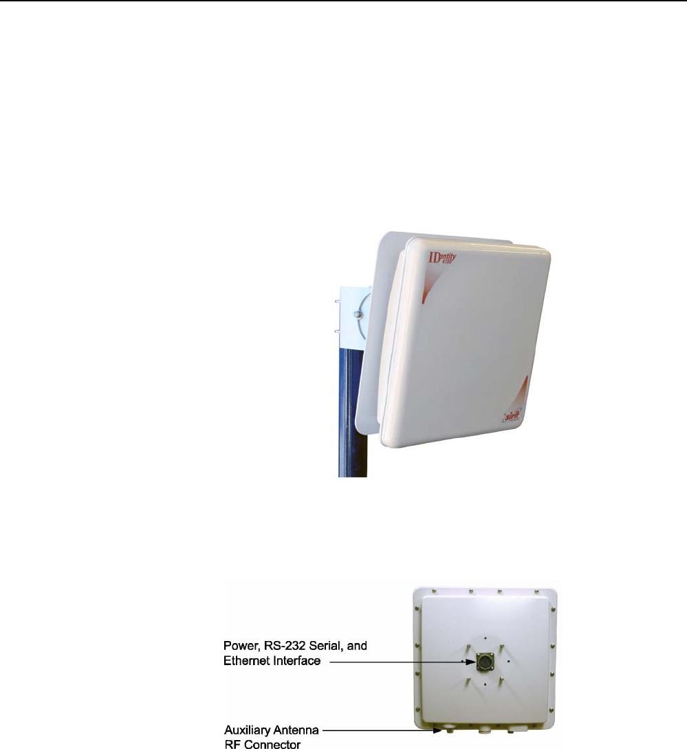
Figure 1
IDentity 4100 UHF Reader with Universal Mount
As shown in the following figure, the IDentity 4100 reader contains one
integrated antenna and supports one additional Tx/Rx antenna. The reader
is equipped with both RS-232 serial and Ethernet interfaces.
Figure 2
IDentity 4100 Power and I/O Connections (FCC reader shown)
1
2 3 4 5 6 7 8 9
Reader Overview
2
IDentity 4100 User Guide
Reader Software
The IDentity 4100 is shipped with two software applications that you can
use to configure and control the reader.
Reader Startup Tool (RST)
The RST is a Microsoft Windows based application you install on your
computer. With RST, you can view all readers on your network. After
selecting a reader, you can modify its communication, network, and
operational parameters. You can also read tags, review tag data, perform
diagnostics, and upload new software. This RST is primarily intended for
initially configuring a reader prior to deployment. After deployment, use the
Embedded Reader Configuration Tool (RCT). Detailed information on the
RST is provided in Chapter 5.
Embedded Reader Configuration Tool (RCT)
This RCT is an embedded reader application that allows you to access your
readers across a LAN or WAN. Enter the IP address of the reader into your
Web browser and the RCT allows you to fully modify and operate the reader.
With the same functionality as the RST, this application allows you to modify
the reader’s communication, network, and operational parameters. You can
also read tags, review tag data, perform diagnostics, and upload new
software. This application is primarily intended for configuring and
managing deployed readers. Detailed information on the RCT is provided in
Chapter 6.
1
2
3 4 5 6 7 8 9
Reader Equipment Installation
IDentity 4100 User Guide
3
Reader Equipment Installation
Mechanical Installation
Mounting the Reader
The IDentity 4100 is available with a universal mount suitable for most
applications. Any mounting surface must be able to support a minimum
static load of 15.0 pounds (6.8 kg) plus any additional live load due to
environmental conditions.
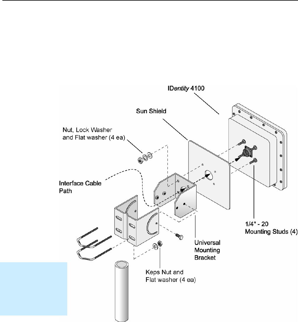
Figure 3
IDentity 4100 Universal Reader Mount
Installation Notice
Installation of the
IDentity 4100 is only to
be performed by
trained, Sirit approved
personnel.

1
2
3 4 5 6 7 8 9
Reader Equipment Installation
4
IDentity 4100 User Guide
To mount the IDentity 4100 reader assembly, refer to Figure 3 and perform
the following:
1 Locate the Universal Mounting Bracket assembly and the Sun Shield.
2 Disassemble the Universal Mounting bracket. Retain all hardware.
3 Locate the Interface Cable.
4 Snake the bulkhead connector end of the Interface Cable through the
Universal Mounting Bracket and then through the Sun Shield.
5 Connect the cable to the reader’s bulkhead connector and twist to lock
in place.
6 For outside applications, install the Sun Shield on the four ¼”-20 studs
located on the rear of the reader. The Sun Shield will be spaced off the
rear approximately 1/2” to allow for air flow.
7 Install the Universal Mounting Bracket on the four ¼”-20 studs.
8 Secure the Universal Mounting Bracket and Sun Shield to the reader
with the four ¼”-20 nuts, lock washers, and flat washers.
9 Install the Pole Mount Bracket to the Mounting Pole using the two U-
Bolts, four Keps Nuts, and four Flat Washers.
10 Adjust the Pole Mount to the proper height and tighten the hardware.
11 Assemble the Universal Mounting Bracket/reader assembly to the Pole
Mount.
12 Adjust the angle of the reader and tighten the hardware.
WARNING:
FCC Radiation Exposure Statement. The antennas used for this transmitter
must be installed to provide a separation distance of at least 1 meter from all
persons and must not be co-located or operating in conjunction with any other
antenna or transmitter.
ETSI Radiation Exposure Statement. The antennas used for this transmitter
must be installed to provide a separation distance of at least 25 cm from all
persons and must not be co-located or operating in conjunction with any other
antenna or transmitter.
1
2
3 4 5 6 7 8 9
Reader Equipment Installation
IDentity 4100 User Guide
5
Electrical Installation
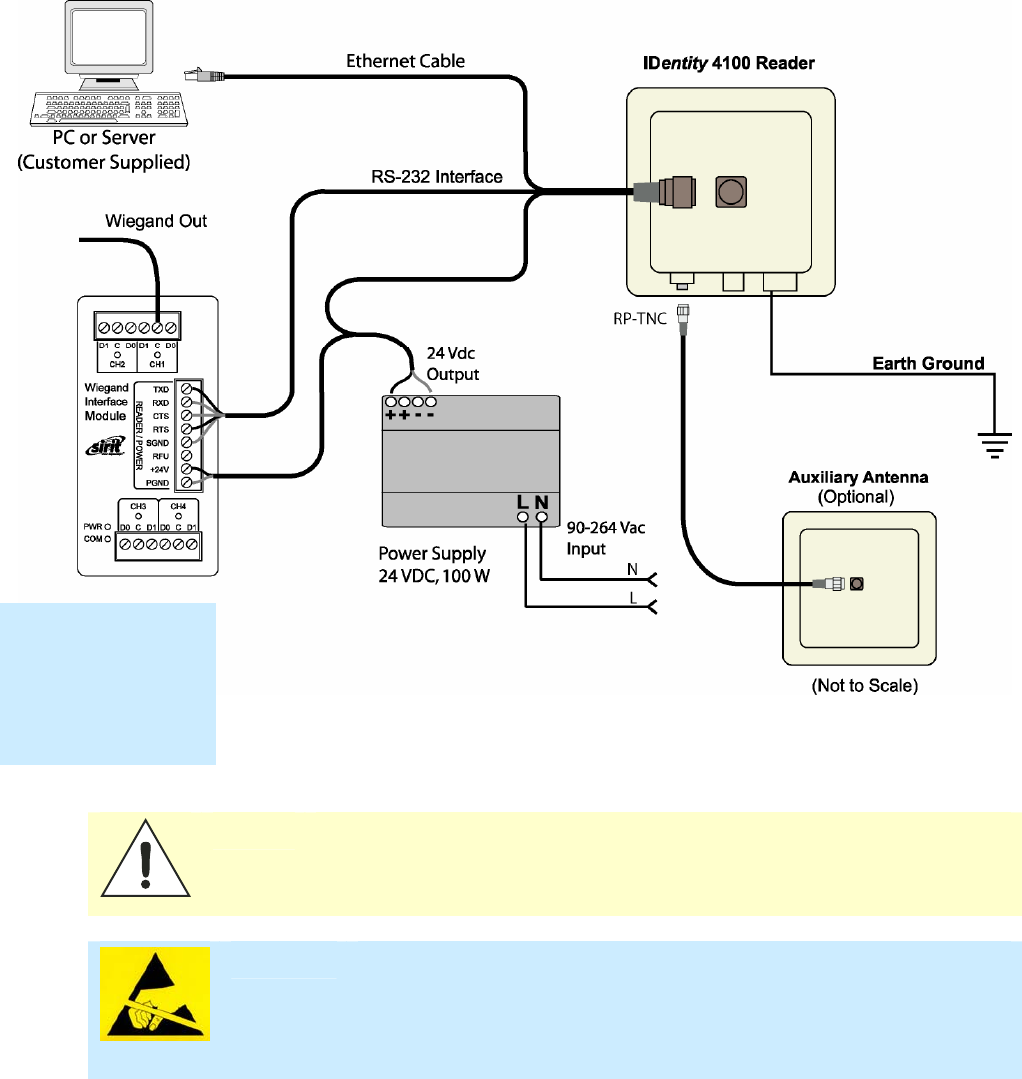
A general installation diagram is shown in the following figure. Refer to
Chapter 7 – Specifications for specific information.
Figure 4 IDentity 4100 Electrical Connections
Caution: The IDentity 4100 is designed to meet the regulatory requirements in those
jurisdictions in which it is offered. Changes or modifications not expressly
approved by Sirit Technologies for compliance could void the user's authority
to operate the equipment.
ATTENTION IDentity 4100 antenna ports may be susceptible to damage from static
discharge or other high voltage. Use proper Electrostatic Discharge
(ESD) precautions to avoid static discharge when handling or making
connections to the IDentity 4100 reader antenna or communication ports.
Equipment failure can result if the antenna or communication ports are
subjected to ESD.
Installation Notice
Installation of the
IDentity 4100 is only
to be performed by
trained, Sirit
approved personnel.

1
2
3 4 5 6 7 8 9
Reader Equipment Installation
6
IDentity 4100 User Guide
Connecting the Serial Port
The IDentity 4100 RS-232 serial port provides communication up to
115200 Baud. This port is accessed through the bulkhead connector
located on the rear of the reader. If you are using the serial port for reader
communication, connect a serial cable from the COM port on your PC to the
serial port on the reader. See Figure 2 for location of the connector.
Refer to the Chapter 8 – Specifications for details on the bulkhead
connector.
Connecting the Wiegand Interface Module
Refer to Appendix A for information on connecting and configuring the
Wiegand Interface Module.
Connecting and Configuring the Ethernet Port
The IDentity 4100 Ethernet port is accessed through the bulkhead
connector located on the rear of the reader. If you are communicating with
your reader across a Local Area Network (LAN), connect an Ethernet cable
from your hub or router to the bulkhead connector. If you are connecting the
reader directly to a PC, you must use a crossover cable. See Note to the left.
By default, the reader is configured to use a DHCP server to obtain its IP
address and related information. In the event a DHCP server is unavailable,
the reader will boot with an IP address in the 169.254.x.x subnet.
In the absence of other readers on the same network, and if no other
network traffic is observed which references 169.254.1.1, the reader will
select that address; otherwise, it will select a random address on the
169.254.x.x subnet.
IP address settings can be changed using RST. Refer to the View or Change
the Reader’s Network Settings section in Chapter 5.
Refer to the Chapter 8 – Specifications for details on the bulkhead
connector.
Ethernet Cables
In most cases, you
will connect the
IDentity 4100 to a
network hub or
router. However, if
you are connecting
directly to a PC or
other computer,
you will need a
Crossover Cable
that swaps the Tx
and Rx signals.

1
2
3 4 5 6 7 8 9
Reader Equipment Installation
IDentity 4100 User Guide
7
Connecting the External Antenna
The IDentity 4100 supports one auxiliary external Tx/Rx antenna. The
maximum antenna cable length is 10 meters for models ID4100-001.
Connect the antenna to the antenna port located on the bottom of the
reader.
Refer to Chapter 7 – Specifications for specific information regarding the
external antenna and antenna cable.
Caution:
The IDentity 4100 is equipped with one (1) auxiliary RF port which is inactive
when shipped from the factory. If activated, this RF port must be properly
terminated with a 50 ohm load or a functional UHF antenna before power up.
Always power down the reader before removing an antenna or load from an RF
port.
The maximum antenna cable length is 10 meters for models ID4100-001.
ATTENTION
The IDentity 4100 antenna port may be susceptible to damage from
static discharge or other high voltage. Use proper Electrostatic
Discharge (ESD) precautions to avoid static discharge when handling or
making connections to the IDentity 4100 reader antenna or
communication ports. Equipment failure can result if the antenna or
communication ports are subjected to ESD.
Connecting Digital Inputs/Outputs
The IDentity 4100 is equipped with a general purpose digital input/output
(I/O) port that provides four optically isolated 5-24 VDC input signals and
four open-collector output signals. The digital inputs can be used as general
purpose inputs or to trigger the reader for tag reading. These inputs can be
configured to provide an external read trigger from proximity sensors, photo
switches, or other devices.
The digital outputs can be used as general purpose outputs, to indicate tag
reading activity, or to indicate the reader is transmitting (RF On). The
outputs can also be configured to trigger gates or other access control
devices.

1
2
3 4 5 6 7 8 9
Reader Equipment Installation
8
IDentity 4100 User Guide
Connecting the Power
The IDentity 4100 operates on 24 VDC provided through the bulkhead
connector on the rear of the reader. Connect the power supply to the reader
and connect the power supply to your 100–240 VAC, 50-60 Hz power
source. Allow 30 seconds for the reader to initialize.
Refer to the Chapter 8 – Specifications for details on the bulkhead
connector.
Two power cables rated for usage at 24V are available for the IDentity
4100:
h
PN S3114-019 – IDMaX-ID5100 20' Cable with RJ-45 Connector
h
PN S3114-011 – IDMAX-ID5100 7' Cable with RJ-45 Connector
Caution:
The Sirit supplied power/data cable is only to be used with the Sirit 24 VDC power
supply. Use of these cables with power supplies providing lesser voltages may
result in cable and/or reader damage.
1 2
3
4 5 6 7 8 9
RST Software Installation
IDentity 4100 User Guide
9
Reader Startup Tool (RST) Software Installation
Installing RST Software
The IDentity 4100 is delivered with a Microsoft Windows based application
called Reader Startup Tool (RST). You can use this application to initially
configure your reader as well as read and display tag data.
NOTE: The product CD provided with your reader contains two setup files: setup.exe and
IDentity_4100_RSTInstaller.msi. The first file, setup.exe, will fully check
your system configuration and load all required software including Microsoft .Net 2.0. If
you only want the RST application, use the IDentity_4100_RSTInstaller.msi
installation file. Note, however, the installation may abort if the required files are not
found on your system.
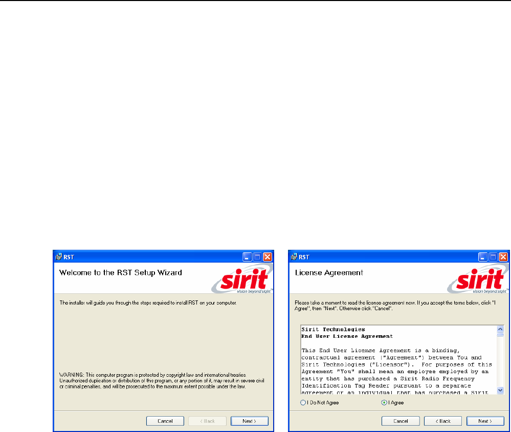
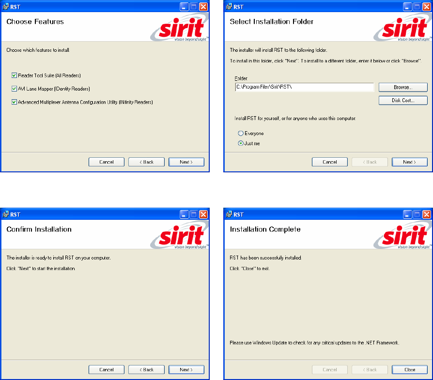
Install RST
1 To install RST, load your product CD and double-click the setup.exe
or IDentity_4100_RSTInstaller.msi file:
2 Press
Next>
3 Read the License Agreement. Select
I Agree
and press
Next>
1 2
3
4 5 6 7 8 9
RST Software Installation
10
IDentity 4100 User Guide
4 Select if you want to install RST, the
RAPID SDK, or both.
5 Verify the path and folder where RST will
be installed. Press
Next>
.
5 Press
Next>.
6 After the installation completes, press
Close.
1 2
3
4 5 6 7 8 9
RST Software Installation
IDentity 4100 User Guide
11
Windows 7 Setup
If you have a Windows 7 operating system, your firewall may block UDP
traffic and consequently RST may not discover your readers. Perform the
following to configure your system:
For Microsoft Firewall
2 Log into your computer as Administrator.
3 Navigate to the Control Panel and select
Control Panel → System and Security
.
4 Select
Allow a program through Windows firewall
.
5 Scroll down the list and locate
Startup Tool
, check it, and press
OK
.
6 If Startup Tool is not in the list, press
Allow another program
.
7 Locate
Startup Tool
, check it, and press
OK
.
8 Restart RST and it should discover readers.
For Third-Party Firewalls
9 Log into your computer as Administrator.
10 Set your firewall to allow RST to receive UDP traffic on port 50000 and
50001.
1 2
3
4 5 6 7 8 9
RST Software Installation
12
IDentity 4100 User Guide
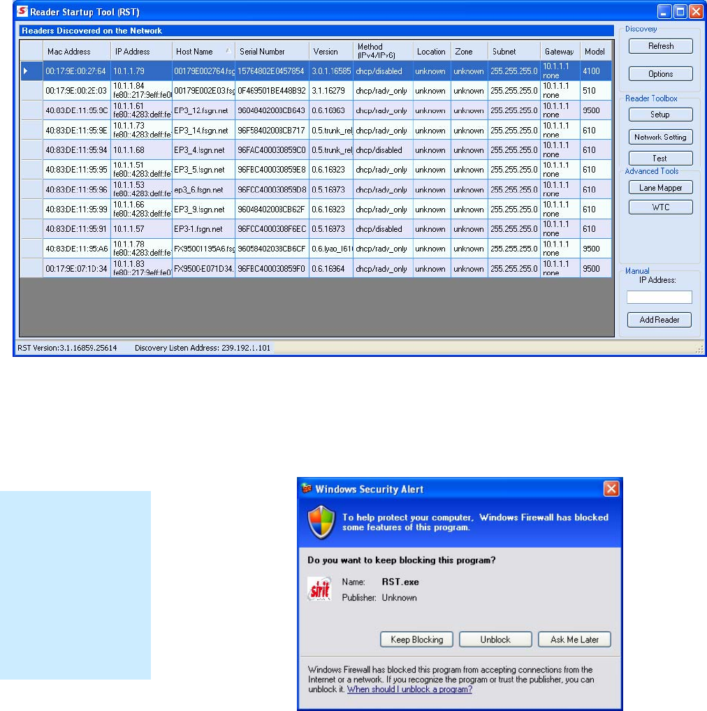
Reader Startup
To begin using your reader, open the RST application.
Open RST
1 From your Windows desktop, select:
Start→Programs→Sirit→IDentity 4100→Reader Startup Tool (RST)
2 If this is the first time starting the RST application, you may receive a
Windows Security Alert. This warning indicates that the firewall is
blocking the RST application.
3 If the warning window is hidden under the RST windows, collapse the
RST window.
NOTE:
Earlier versions of
Microsoft Windows™
may not provide the
Security Alert popup.
IF RST does not
discover your reader,
check your Windows
Firewall/Security
settings.
1 2
3
4 5 6 7 8 9
RST Software Installation
IDentity 4100 User Guide
13
4 Press
Unblock
.
5 Press
Refresh
on the RST
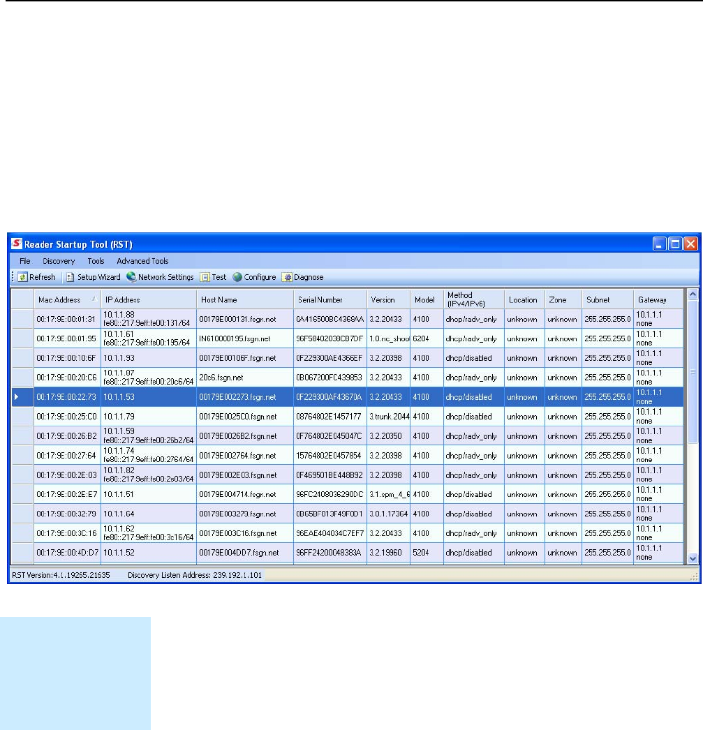
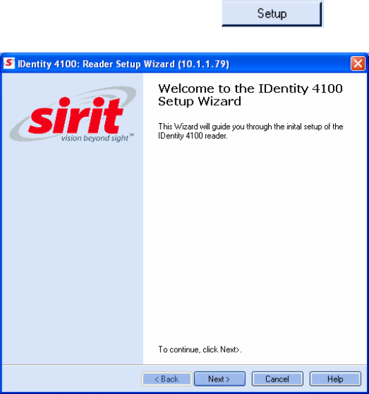
6 The RST main page will display any readers currently connected to the
network.
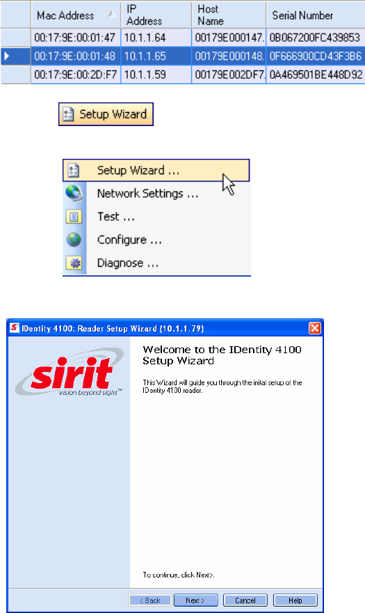
Initial Reader Setup
To configure a specific reader, perform the following:
Reader Setup
1 Select the reader on the main RST page by clicking the button to the
left of the reader Mac address.
2 Press the button on the RST tool bar or select
Setup
Wizard
from the
Tools
pull-down menu.
3 The IDentity 4100 Reader Setup Wizard (RSW) is displayed.
1 2
3
4 5 6 7 8 9
RST Software Installation
14
IDentity 4100 User Guide
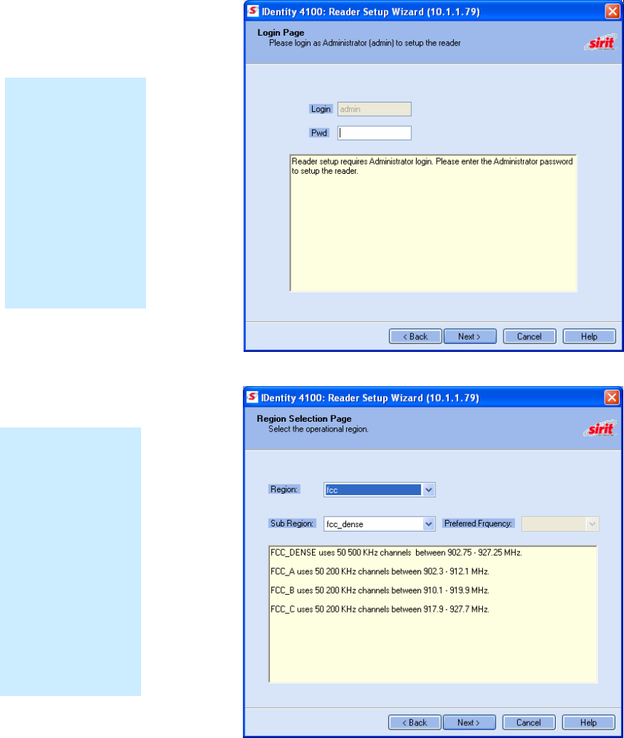
4 Press
Next>
5 Readers leave the factory with a default login level set to admin. If
your reader has a default login level set to guest, you will see the
following screen. Enter the Login (admin) and Password. If this is the
first time configuring your reader, enter: readeradmin.
6 After entering your Login and Password, press
Next>
.
7 Select your Region and Sub Region and press
Next>
.
Region Selection
The reader is
configured at the
factory to operate
within a specific
regulatory region. As
a result your region
selections may be
different from those
shown in this
manual.
Note that Region
Selection is not user
configurable.
Login Page
The reader Login
Page is only
displayed when the
default login is set to
guest. Readers
leave the factory with
a default login of
admin. Therefore,
you will not see the
login screen if you
have not configured
your reader.
1 2
3
4 5 6 7 8 9
RST Software Installation
IDentity 4100 User Guide
15
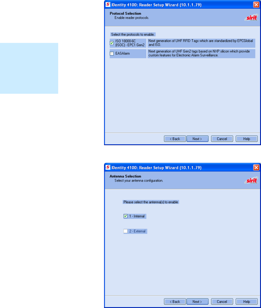
8 Select the protocols to read and press
Next>
.
9 Select the antennas you will be using and press
Next>
.
Protocols
Only those protocols
enabled in the reader
will be active on the
Protocol Selection
page.
1 2
3
4 5 6 7 8 9
RST Software Installation
16
IDentity 4100 User Guide
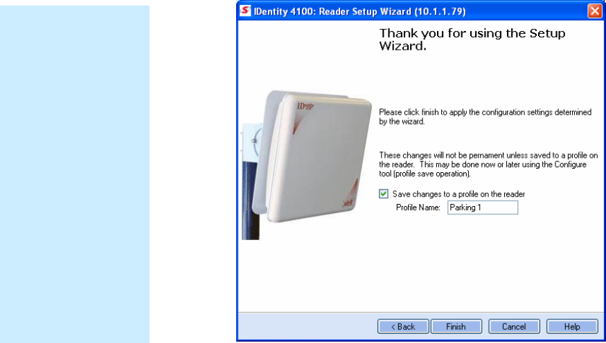
10 It is recommended that you save the reader setup as a profile.
Select
Save changes to a profile…
, enter a
Profile Name
, and press
Finish
to complete the initial reader setup. See Manage Profiles in
Chapter 6.
Converting Translation Tables for use with IDentity 4100
If you have translation tables, such as those developed for IDentity MaX
readers, these tables can be converted for use with the IDentity 4100 and
Wiegand Interface Module. Refer to Appendix A for instructions on
converting these translation tables.
Save Reader Setup
Reader setup
information should be
saved as a profile. In
the event that you
need to reboot or
power down a reader,
the reader setup can
be quickly reloaded
by loading the profile.
If you don’t save the
reader setup, you can
loose the information
if the reader is
rebooted.
Refer to the Manage
Profiles section in
Chapter 6 –
Embedded Reader
Configuration Tool.
1 2 3
4
5 6 7 8 9
Reader Operation
IDentity 4100 User Guide
17
Reader Operation
Basic Operation with RST
The IDentity 4100 can be operated either from the RST application or by
logging directly into the reader’s embedded Reader Configuration Tool
(RCT). To operate the reader from RST, perform the following:
Open RST
1 From your Windows desktop, select:
Start→Programs→Sirit→IDentity4100→Reader Startup Tool (RST)
2 Select a specific reader and press
Test
.
3 The Reader Test Tool (RTT) is displayed.
4 Login to the reader as administrator. From the pull-down menu, select:
Reader → Login
The login is admin and the initial password (
Pwd
) is readeradmin.
See the Advanced Setup section for details on changing the password.
Customize the display
Customize your RST
display by clicking
and dragging the
columns. You can
also sort by column.
1 2 3
4
5 6 7 8 9
Reader Operation
18
IDentity 4100 User Guide
5 Verify the
Operating Mode
is set to
Active Mode
. Select:
Operating Mode → Active
6 Select the
Tag Performance
tab and press
Start
.
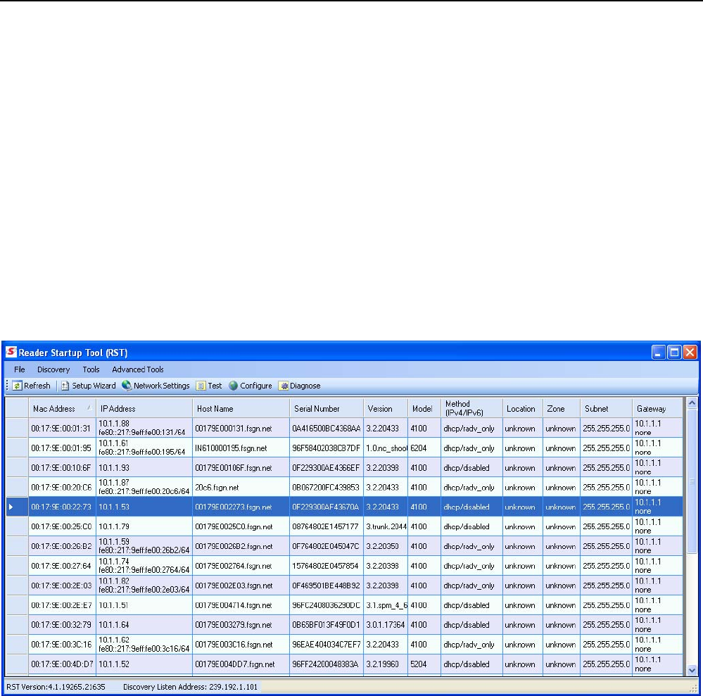
7 Place your tags in front of the antenna and verify the tags are read and
displayed as shown in the following figure.
1 2 3
4
5 6 7 8 9
Reader Operation
IDentity 4100 User Guide
19
Deployed Reader Operation with RCT
Once your readers are deployed, you can access them directly using the
embedded Reader Configuration Tool (RCT). To access a particular reader,
perform the following:
11 Enter the reader’s IP address into your Web browser or press the
button on the main RST page.
12 The reader’s RCT interface is displayed.
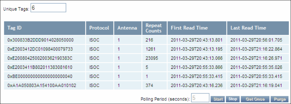
13 Log into the reader. Press
Login
for the login screen.
14 The default login is
guest
. If you need administrator privileges, login as
admin
and enter
readeradmin
as the password.
15 Press
Submit
.
16 Select
Basic Configuration
→
Setup Antenna/Cables
to configure the
antennas, gain, and power settings.
1 2 3
4
5 6 7 8 9
Reader Operation
20
IDentity 4100 User Guide
17 Select
Advanced Functions
→
Change Operating Mode
to verify the
reader is in the proper mode.
18 Select
Basic Configuration
→
Set Tag Protocol
to verify the reader is
configured for the proper tag protocol.
19 Press
System Status
→
View Tags
to view tag data.
20 Press
Start.
21 If you need to configure your reader, refer to Chapter 7 – Reader
Configuration Tool for information on using RCT to adjust configuration
variables and parameters.
1 2 3 4
5
6 7 8 9
Reader Startup Tool
IDentity 4100 User Guide
21
Reader Startup Tool (RST)
The Reader Startup Tool (RST) provides an easy-to-use interface for the
IDentity 4100 configuration and operation functions. This Microsoft
Windows based application allows you to perform the following:
h View all readers on the network
h Launch the
Reader Setup Wizard
to initially configure a reader
h View and change a reader’s network settings
h Add a new reader to the network
h Launch
Reader Test Tool
to perform basic reader/tag operations
h Launch
Reader Diagnostic Tool
to view statistics, alarms, and reports
h Launch
Reader Configuration Tool
to perform detailed reader
configuration
View Readers on the Network
When RST starts up, all readers currently connected to the network and
powered up are displayed.
1 2 3 4
5
6 7 8 9
Reader Startup Tool
22
IDentity 4100 User Guide
Configure Reader with the Setup Wizard
The Reader Setup Wizard is used to initially configure your reader for
operation. With this application, you can select the following:
h Regulatory region (fixed at factory) and sub-region
h Preferred Frequency (depending on regulatory settings)
h Number of antennas
To initially configure your reader perform the following:
22 From the RST main page, press the button. The Setup
Wizard is launched as shown.
23 Refer to Chapter 2 – Reader Configuration for detailed instructions on
using the Reader Setup Wizard.
1 2 3 4
5
6 7 8 9
Reader Startup Tool
IDentity 4100 User Guide
23
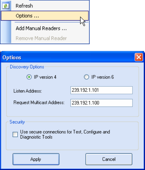
Customize Discovery Options
You can customize the reader discovery options including the Listen
Address and Request Multicast Address.
h Listen Address – Address that RMT uses to listen for UDP discovery
packets from the reader. With Version 2.0 this is customizable on the
reader.
h Request Multicast Address –Address used by RMT to send out the UDP
update request packets. With 2.0 this is now customizable on the
reader.
In addition, you can select if you want a secure connection for the Test,
Configure, and Diagnostic Tools. This connection uses the HTTPS protocol
and any data transferred between devices is encrypted.
1 On the RST tool bar select
Options
from the
Discovery
pull-down
menu.
2 Select either
IP version 4
or
IP version 6
.
3 Enter the
Listen Address
and
Request Multicast Address
as required.
4 Select whether you require a secure connection for the Test, Configure,
and Diagnostic Tools.
5 Press
Apply
.
1 2 3 4
5
6 7 8 9
Reader Startup Tool
24
IDentity 4100 User Guide
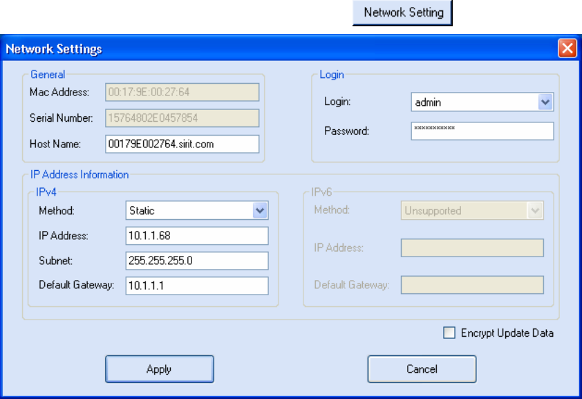
View or Change the Reader’s Network Settings
The Network Settings dialog allows you to change the IP Address, Subnet,
and Default Gateway of your reader. For readers with firmware version 2.0
or later, a password is required to make any changes.
1 From the RST main page, press the button.
2 Verify the
IP Address
,
Subnet
, and
Default Gateway
are correct.
3 If
Enable DHCP
is selected these fields will be locked.
4 If changes are required, enter your
Login
and
Password
(V2.0 and
later).
5 Change the values and press
Apply
.
1 2 3 4
5
6 7 8 9
Reader Startup Tool
IDentity 4100 User Guide
25
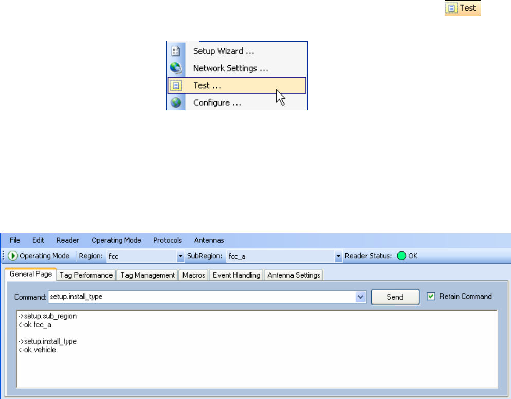
Reader Test Tool (RTT)
The Reader Test Tool (RTT) is primarily designed for new users to test
reader operation and perform a few basic reader functions. With RTT, you
can perform the following:
h Read tags
h Issue commands to the reader and view the responses
h Run macros
h Observe reader events
h To access the Reader Test Tool, select a reader and press on
the RST tool bar or select
Test
from the
Tools
pull-down menu.
General Page
The
General Page
allows you to issue commands to the reader and view
any responses. From the pull-down menus, you can also login to the reader,
change the operating mode, select another protocol, and select which
antennas are active.
1 2 3 4
5
6 7 8 9
Reader Startup Tool
26
IDentity 4100 User Guide
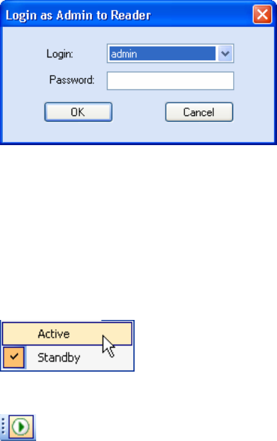
Login to Reader
To login to the reader, perform the following:
6 From the pull-down menu, select
Reader→Login…
.
7 Select the type of
Login
from the pull down. The default login is
guest
.
If you need administrator privileges, login as
admin
.
8 Enter your
Password
. Enter
readeradmin
if you logged in as
admin
.
9 Press
OK
.
Select Operating Mode
From the pull-down menu, select
Operating Mode→<Active | Standby>
or, press the Operating Mode select button on the left side of the tool bar.
h
Active
– Reader is continuously attempting to singulate tags and
automatically reports any singulated tag via an asynchronous event
notification on the event channel.
h
Standby
– Reader is not transmitting any RF energy, unless processing
a tag related command. The transmitter is enabled at the beginning of
the command processing, protocol operations required for the
command are performed, and then the RF transmitter is turned off.
1 2 3 4
5
6 7 8 9
Reader Startup Tool
IDentity 4100 User Guide
27
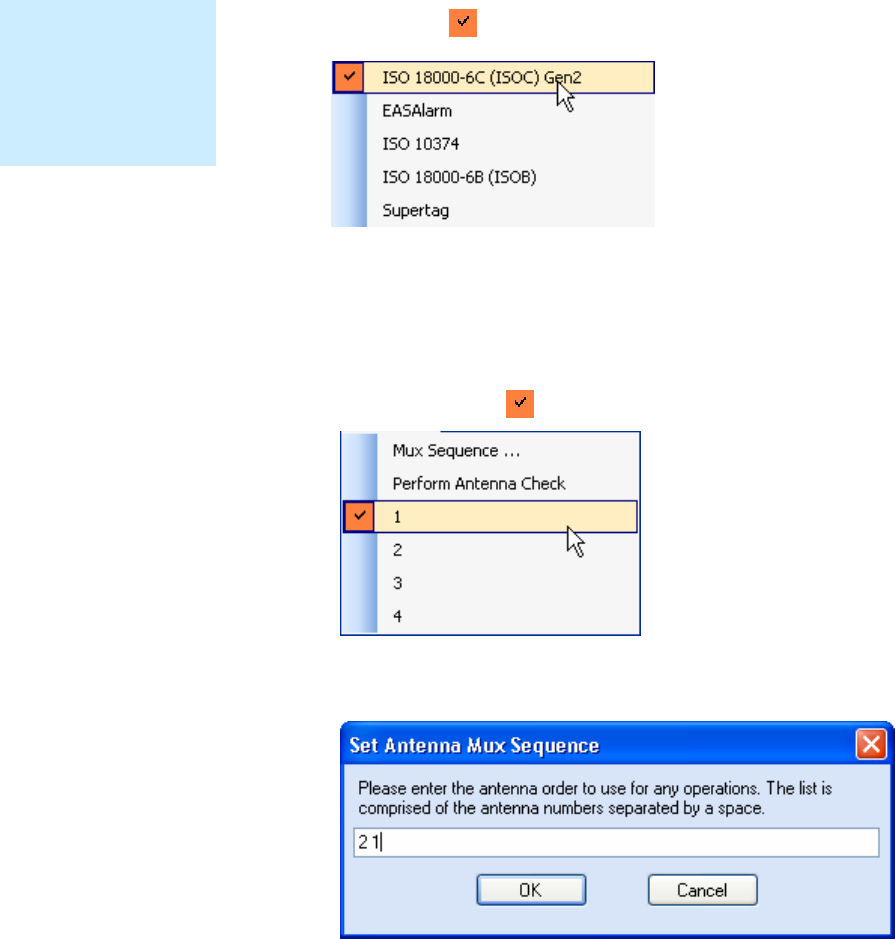
Select Protocol
You can activate one or more protocols on the IDentity 4100 using RST.
From the pull-down menu, select
Protocols→<protocol
>.
Active protocols
are indicated by .
Antenna Selection
You can select the ports that have antennas connected and which antennas
are active. Perform the following:
10
From the pull-down menu, select
Antennas→<n>.
Active antennas
are indicated by .
11
You can also select the order in which antennas are activated. From the
pull-down menu, select
Antennas→Mux sequence....
12 Enter the antenna numbers in the order to be activated.
13 Press
OK
.
NOTE
Certain protocols
require licensing and
may not be available.
Contact Sirit for more
information.
1 2 3 4
5
6 7 8 9
Reader Startup Tool
28
IDentity 4100 User Guide
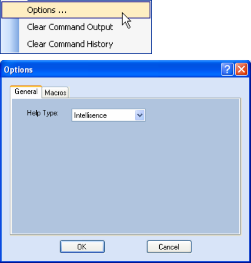
Set Reader Options
You can setup other reader options including help type macro highlighting.
From the pull-down menu, select
Edit→Options.
1 2 3 4
5
6 7 8 9
Reader Startup Tool
IDentity 4100 User Guide
29
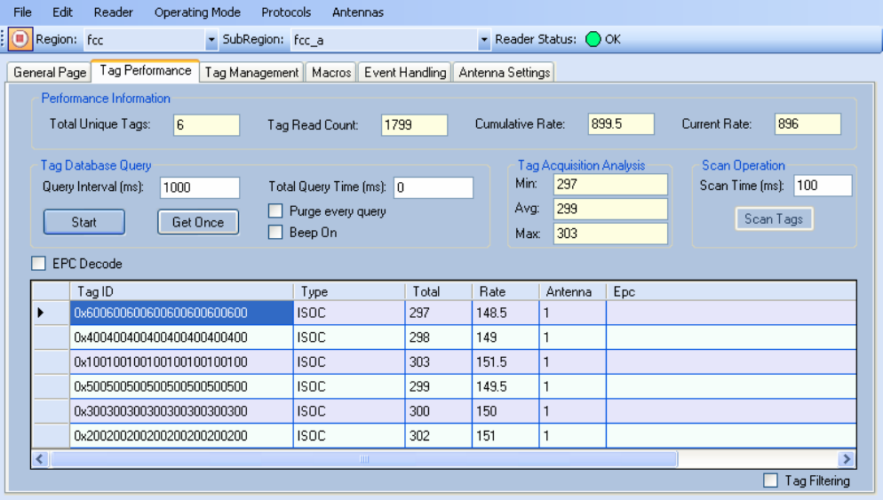
RTT - Tag Performance Page
The
Tag Performance
page is used to test the reader performance. This
page is useful for range (distance) testing and to verify the RF field size.
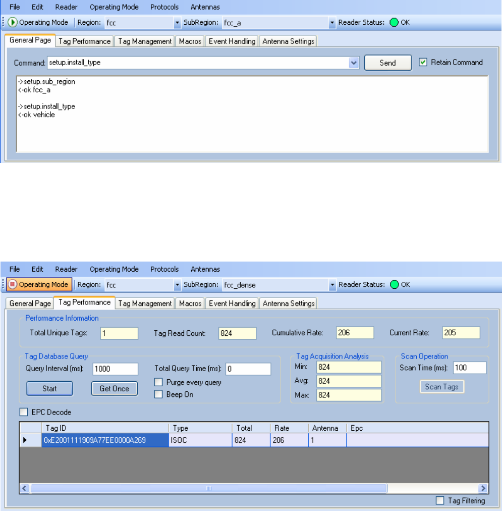
To initiate a timed test, enter the length of test (in ms) into the
Total Query
Time
field. For example, to verify to number of tags read in a 30-second
interval, select
Active
Operating Mode, enter 30000, and press the
Start
button. The test will complete after 30 seconds and the output statistics are
updated for the poll time.
Output statistics are read-only and include: Total Unique Tags, Tag Read
Count, Cumulative Rate, Current Rate.
Detailed descriptions of the various
Tag Performance
fields and functions
are provided in the following sections.
Tag and reader performance data is provided in the
Performance
Information
and
Tag Acquisition Analysis
blocks.
1 2 3 4
5
6 7 8 9
Reader Startup Tool
30
IDentity 4100 User Guide
Performance Information
Total Unique Tags
– Number of unique tags in the tag database.
Tag Read Count
– Total number of tags read (including repeat reads).
Cumulative Rate
– Cumulative read rate in tags/second since the
Start
button was pressed.
Current Rate
– Current read rate in tags/second.
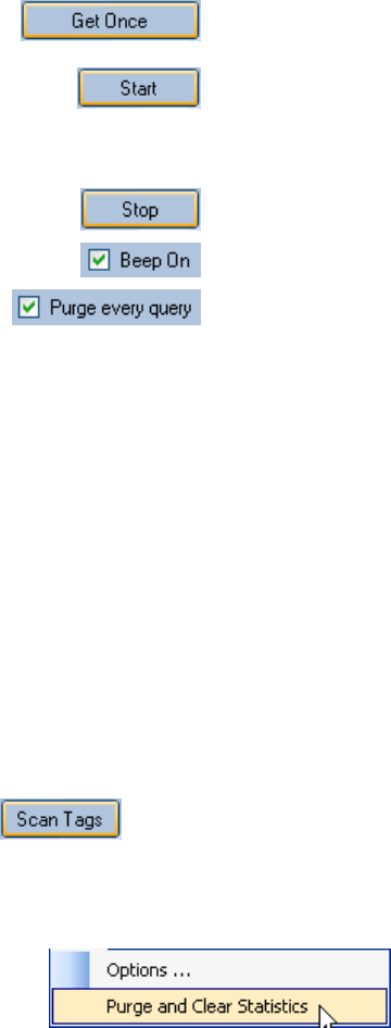
Tag Database Query Controls
Click to retrieve the current information from reader’s
tag database.
Click to query the tag database every
Query Interval
(ms)
for a total time of
Total Query Time (ms)
. Do not
set the interval less than 500. If Total Query Time is
set to 0, query continues indefinitely.
Click to stop automatic query.
Indicates current read rate with audible tone.
Check to purge the reader’s tag database after each
query. Refer to the IDentity 4100 Protocol Reference
Guide for more information on the tag database.
Tag Acquisition Analysis
The
Tag Acquisition Analysis
fields provide the minimum, maximum, and
average number of times each tag was read. For example, assume five tags
(A, B, C, D, and E) are read 107, 59, 223, 187, and 94 times respectively.
The displayed values are as follows:
Min
= 59
Avg
= 134
Max
= 223
Scan Operation
Scan time (ms)
– Enter the duration of reader operation in milliseconds.
After this time expires, the tag information is displayed.
Press this button to activate the reader.
Purge and Clear Reader Statistics
Select the reader and then select
Edit→Purge and Clear Statistics.
1 2 3 4
5
6 7 8 9
Reader Startup Tool
IDentity 4100 User Guide
31
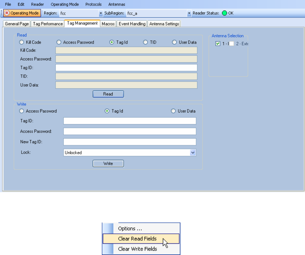
RTT - Tag Management Page
The
Tag Management
page is used for reading individual fields on a single
tag. The
Read
button will cause the reader to singulate and read a tag in the
selected antennas' RF field. You can also write the Access Password, User
Data, and Tag ID. Specific fields you can read and write include:
h Kill Code
h Access Code
h Tag ID
h TID
h User Data
Clear Read and Write Fields
To clear the Read or Write fields, select
Edit→Clear….
1 2 3 4
5
6 7 8 9
Reader Startup Tool
32
IDentity 4100 User Guide
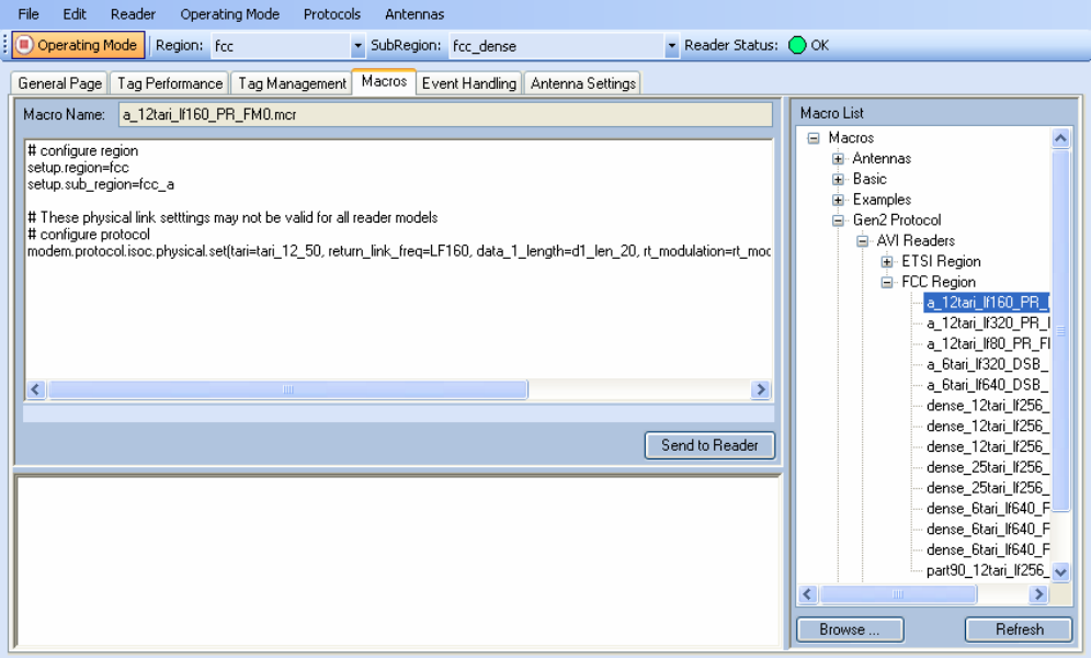
RTT - Macros Page
The
Macros
page allows the reader to manage macro files. The macros are
provided by Sirit or can be written by the end user. Some of the macros
provided are dependent on the operating region of the reader.
A macro (script or command file) is a text file that contains one or more
reader commands. These commands are used to configure the reader to a
known configuration. The Macros can contain variables. These variables are
resolved by a dialog box (
Macro Variables
) that appears when the
Send to
Reader
button is selected. The syntax of a variable is:
[$variable_name]
During execution, the variable is replaced with user entries in the
Macro
Variables
dialog box. Macros can be edited with any text editor including
Windows Notepad.
1 2 3 4
5
6 7 8 9
Reader Startup Tool
IDentity 4100 User Guide
33
Macro Input sub-window
The
Macro Input
window shows the current script that will be sent to the
reader when the
Send to Reader
button is selected. The text in the
Macro
Input
window can be edited prior to being sent to the reader.
Macro Output sub-window
The
Macro Output
window is updated after the
Send to Reader
button is
selected. Look at this window to verify that each command line in a script
executed correctly. Look for the
−−>> ok
response from the reader for each
command line.
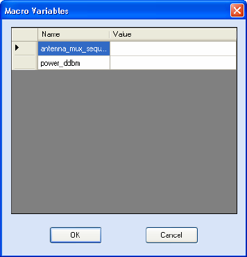
Macro Variables Dialog box
When a macro is sent to the reader,
the values for variables must be
resolved via this Windows Dialog
box. You can
[tab]
to each value
field and enter the desired value.
For example, one macro can be
used for two different applications
by using variables for antenna
selection and transmit power.
Macro Example
To configure the reader for FCC, Part 90 Dense operation, send the
following macro (
part90_6tari_lf640_PR_M2.mcr
):
# configure region
setup.region=fcc
setup.sub_region=fcc_part90
# set frequency
setup.advanced.preferred_frequencies=915950
# configure protocol
modem.protocol.isoc.control.auto_phy.enable=false
modem.protocol.isoc.physical.set(tari=tari_06_25,
return_link_freq=LF640, data_1_length=d1_len_20,
rt_modulation=rt_mod_pr,
tr_encoding=tr_enc_miller_2,interrogator_mode=dense)
1 2 3 4
5
6 7 8 9
Reader Startup Tool
34
IDentity 4100 User Guide
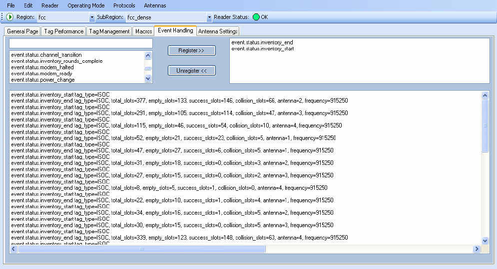
RTT - Event Handling Page
The
Event Handling
page allows you to register for Reader Events. After
registration, events will be displayed as they occur in the window. Individual
events or a group of events can be registered. Events are displayed with the
newest event on the bottom and scrolled up as new events are added to the
window. The least recent event will scroll to the top of the window.
For detailed information on individual events, refer to Chapter 18 – Events
Namespace of the IDentity 4100 Protocol Reference Guide.
Registering for an individual event
To register for an individual event, either type the event name or select an
event from a pull-down list.
Registering for a group of events
Registering for
event.error
events, will cause the reader to autonomously
send all events in the
event.error
namespace to the RTT program and be
displayed in the window of this page. Enter
event.error
in the
Events:
field
and press the
Register
button. The
Clear
button can be selected at any
time to clear the window.
1 2 3 4
5
6 7 8 9
Reader Startup Tool
IDentity 4100 User Guide
35
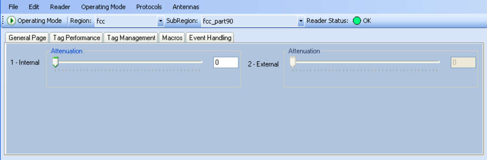
RTT - Antenna Settings Page
The
Antenna Settings
page allows you to adjust the power settings for each
antenna. Only the controls for those antennas that are connected are
activated.
1 2 3 4
5
6 7 8 9
Reader Startup Tool
36
IDentity 4100 User Guide
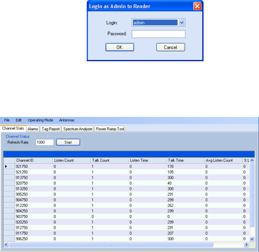
Reader Diagnostics Tool (RDT)
The Reader Diagnostic Tool (RDT) is to be used by Sirit trained technicians
to troubleshoot and diagnose various reader issues. Administrator login is
required.
To use RDT, you must login as an administrator, perform the following.
When you first start RDT, the following login will appear:
Enter your
Password
. Enter
readeradmin
or your current administrator
password. Press
OK
.
Channel Statistics
The
Channel Stats
page shows details of channel changes. This page is
typically used to observe regional behavior.
1 2 3 4
5
6 7 8 9
Reader Startup Tool
IDentity 4100 User Guide
37
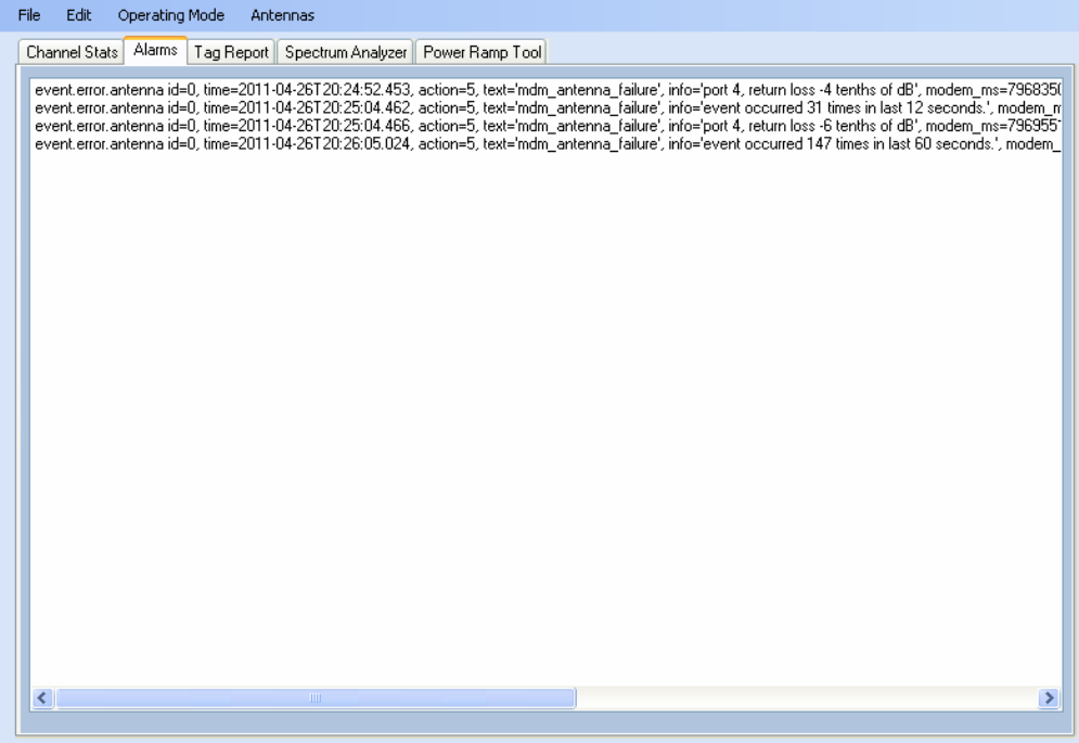
RDT - Alarms
The
Alarms
page is used to capture autonomous alarms generated by the
reader during normal operation. The alarms are defined as autonomous
reader events for the following namespaces:
event.error
event.warning
1 2 3 4
5
6 7 8 9
Reader Startup Tool
38
IDentity 4100 User Guide
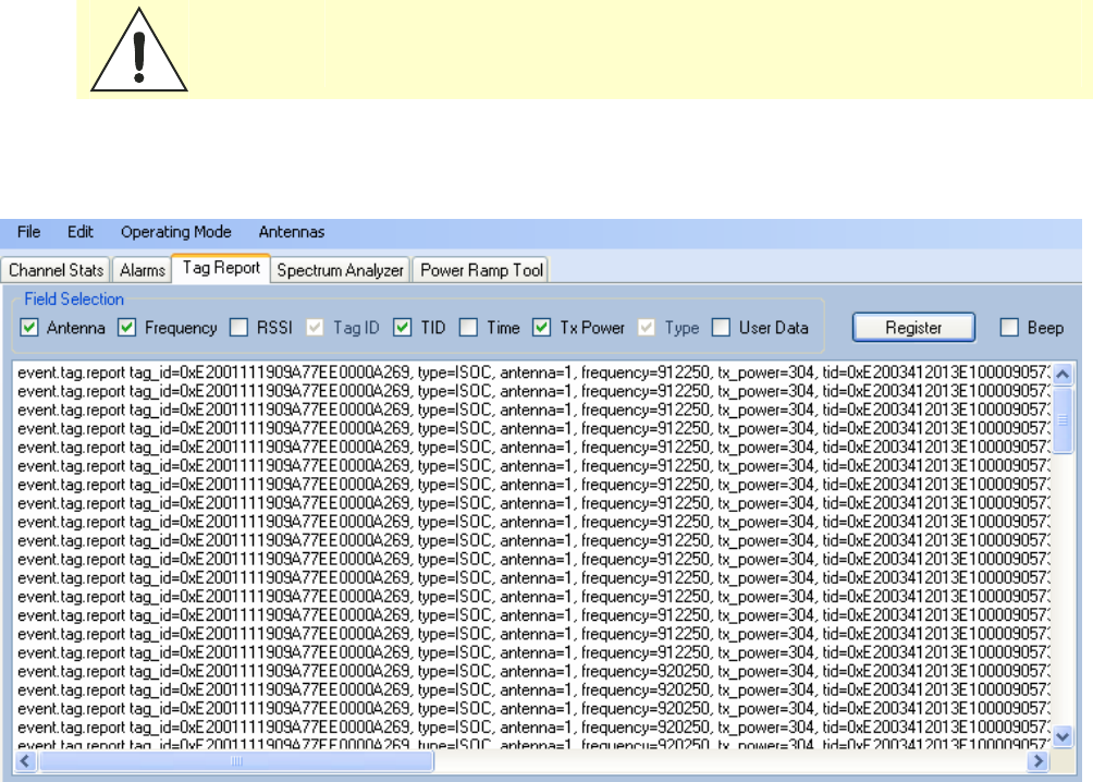
RDT - Tag Report
The Tag Report page is used to view specific information for each tag
singulation. This feature provides detailed attributes of tag singulations
such as tag power (RSSI) and on which antenna that tag singulated.
Caution:
Use of this tool can adversely affect tag reader performance, particularly if many
tag fields are enabled. Use the RTT->Tag Performance page for normal tag
performance testing.
1 2 3 4
5
6 7 8 9
Reader Startup Tool
IDentity 4100 User Guide
39
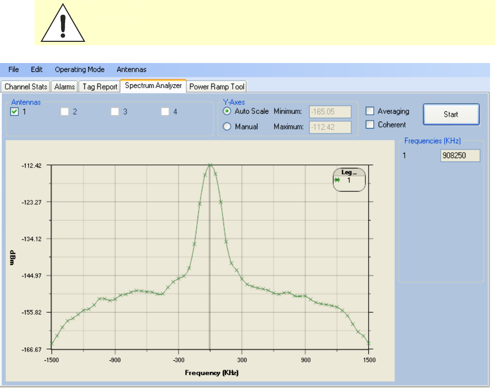
RDT - Spectrum Analyzer
The Spectrum Analyzer allows you to examine the spectral composition of
the radio waves in your surrounding environment. This feature provides a
graphical representation of the current spectral RF noise in units of dBm
with a range of 0 to -120 dBm. This feature is intended for expert users to
verify RF environmental conditions during an installation.
Set the
Center Frequency
and
Span
fields to view the desired range of
frequencies. The Spectrum Analyzer settings are saved and are recalled
when RDT is restarted the next time.
Caution:
Using this feature during normal reader operation can significantly degrade tag
reading performance.
1 2 3 4
5
6 7 8 9
Reader Startup Tool
40
IDentity 4100 User Guide
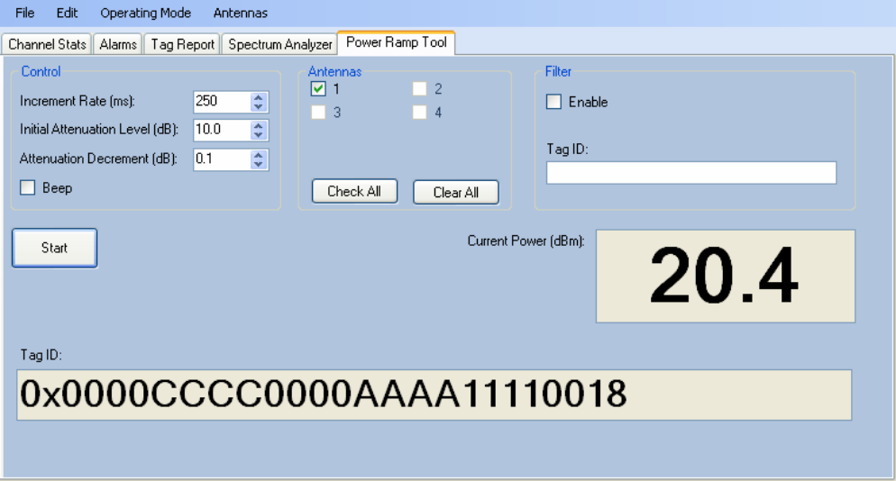
Power Ramp Tool
The Power Ramp Tool determines the minimum power to activate a tag and
can help determine tag quality. This activation power level can help
determine the read range at various attenuation levels and, for AVI
applications, can help determine the "read-zone" or an antenna pattern.
The tool starts by configuring the reader to start transmitting at a high
attenuation level (usually maximum allowed for reader) and decrements the
level until it observes a response from the tag. The transmitter is turned off
and the minimum value to activate the tag for a given antenna and distance
is reported.
The Power Ramp controls include:
h Increment Rate (ms) – Time tool stays at a particular power level
before incrementing to the next power level.
h Initial Attenuation Level (dBm) – Starting attenuation level.
h Attenuation Decrement (dBm) – Step-size for attenuation
decrement.
h Antennas section allows you to select which antenna(s) to test with.
h Filter section allows you to apply a filter to only look for a particular tag.
1 2 3 4
5
6 7 8 9
Reader Startup Tool
IDentity 4100 User Guide
41
AVI Lane Mapper
The AVI Lane Mapper application determines the tag read rate and the
signal strength of tags in toll lane antenna field. This helps identify weak
and strong areas within the antenna field.
Please refer to Appendix A for information on using the AVI Lane Mapper
application.
1 2 3 4 5
6
7 8 9
Reader Configuration Tool
42
IDentity 4100 User Guide
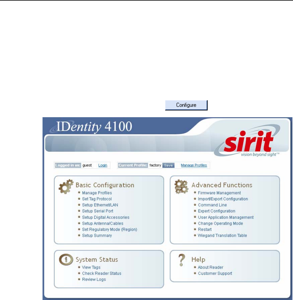
Embedded Reader Configuration Tool (RCT)
The Embedded Reader Configuration Tool (RCT) allows you to access your
reader across a LAN or WAN by entering the reader’s IP address into your
web browser. With the RCT, you can fully configure your reader for operation
in a variety of applications and environments. With this application, you can
perform the following:
h Basic Configurations
h Advanced Configurations
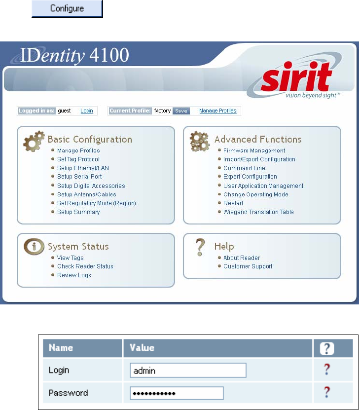
h Check System Status
h Access the online Help
To access the RCT, press the button on the main RST page.

1 2 3 4 5
6
7 8 9
Reader Configuration Tool
IDentity 4100 User Guide
43
Basic Configuration
With the Basic Configuration functions you can perform the following:
h Manage reader profiles
h Set tag protocols
h Setup the Ethernet/LAN configuration
h Setup the serial port
h Setup digital accessories
h Setup antennas/cables
h Set regulatory modes
h View setup summary
Configuration Page Header
Each page displayed by the RCT has the following header.
This header provides pull-down menus for each of the configuration
function categories. Additional functions include the user login and the
currently loaded reader profile.
Login
The reader’s default user level is
guest
. However, a user can login as
admin
. If not logged in as
admin
, the default level is always
guest
.
The guest login level provides read-only access to the reader. Clients that
login in at the guest level can read the settings of the reader and can
access the tags that the reader has inventoried. Clients at this level cannot
change the configuration of the reader.
The admin login level provides read-write access to the reader. Clients that
login in at the admin level can read and write the settings of the reader and
can access the tags that the reader has inventoried.
Logout
After logging in as
admin
, the
Logout
button logs you out of the reader.
Logging out automatically sets the login level to guest.
Profile
Profile is the currently active profile in the reader. Refer to the Manage
Profiles section for detailed information on reader profiles.
1 2 3 4 5
6
7 8 9
Reader Configuration Tool
44
IDentity 4100 User Guide
Save
The Save button saves the reader's current configuration to the specified
profile. Refer to the Manage Profiles section for detailed information on
reader profiles.
Manage Profiles
This link allows you to list, save, and delete profiles. Refer to the Manage
Profiles section for detailed information on reader profiles.
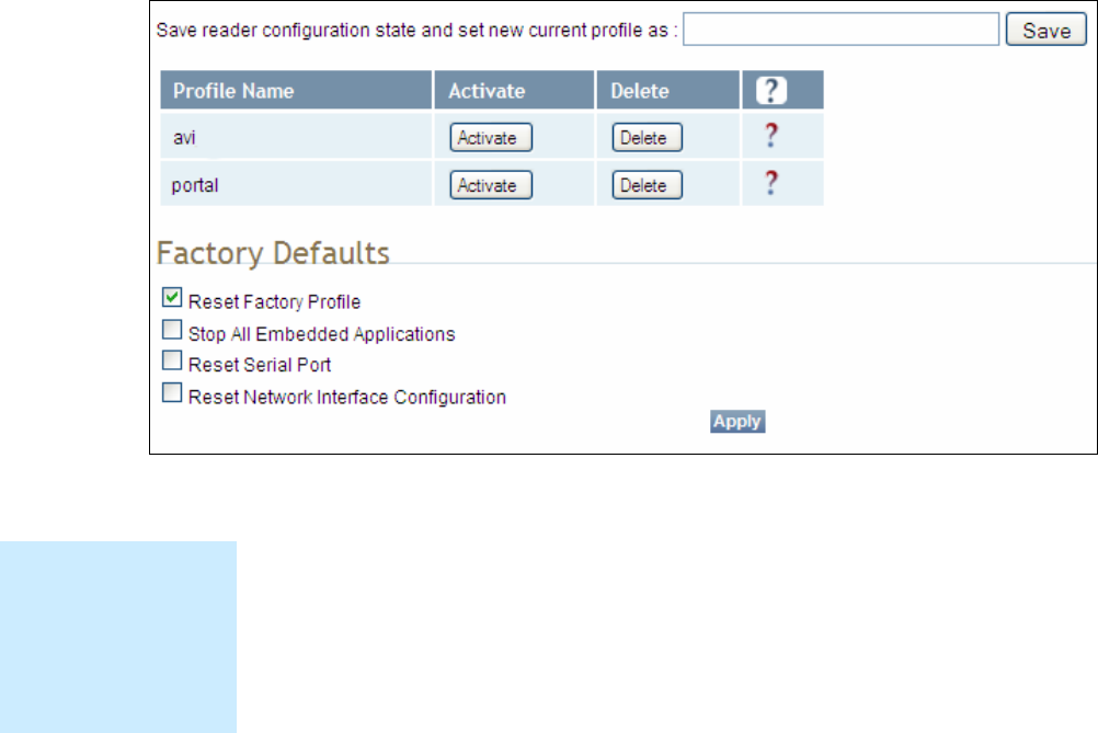
Manage Profiles
The reader’s configuration is stored in a profile. A profile contains the
setting of all the configuration variables in the reader. The reader can
support up to 8 unique profiles. Detailed information about reader profiles
is provided in Chapter 4 – Reader Behavior of the IDentity 4100 Protocol
Reference Guide.
The
Manage Profiles
page provides a list of all profiles stored in the reader.
Save a Profile
To save your current reader configuration under a new profile, enter a
profile name and press
Save
. The new profile will appear in the Profile
Name list. Profile names must consist of the characters A - Z, a - z, 0 - 9, '-'
or '_' and must be between 1 and 32 characters in length. The reader can
store up to 8 different profiles.
Profile Names
The profile name
factory is reserved
and cannot be used.
This profile is a read
only profile.
1 2 3 4 5
6
7 8 9
Reader Configuration Tool
IDentity 4100 User Guide
45
Activate a Profile
To activate a previously saved profile, press the
Activate
button beside the
profile name. The selected profile will be loaded into the reader.
Delete a Profile
To delete a previously saved profile, press the
Delete
button beside the
profile name. This is a destructive operation. Once a profile is deleted, it
cannot be recovered.
Reset to Factory Default
In addition to managing reader profiles, you can also reset the reader back
to its factory default configuration. From the Profiles page select one or
more of the following:
h
Stop All Embedded Applications
– This option terminates any
embedded applications currently running on the reader.
h
Reset Serial Port
– This option resets the serial port configuration to
the factory default settings.
h
Reset Network Interface Configuration
– This option resets the network
configuration to factory defaults.
1 2 3 4 5
6
7 8 9
Reader Configuration Tool
46
IDentity 4100 User Guide
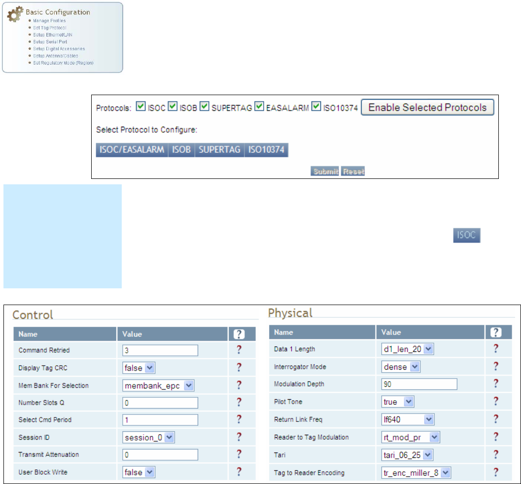
Set Tag Protocol
This
Set Tag Protocol
page consists of two forms. The first form (top) allows
you to select which type of tags the reader will acquire or the type of
protocol(s) to utilize on the air interface. Currently, the reader can operate
with either ISO18000-6C (ISOC), ISO18000-6B (ISOB), SuperTag,
ISO10374, EASALARM,
Flex, ISOB_80K,
or any combination.
Select the check box for the protocol(s) to enable and then press
Enable
Selected Protocols
to activate the protocol.
To configure protocol level parameters, select the protocol button .
The protocol level parameters are divided into two categories: control and
physical. Control parameters configure the protocol control. Physical
parameters configure the physical air interface for the protocol.
For detailed information on each of the Control and Physical parameters,
refer to Chapter 15 – Modem Namespace of the IDentity 4100 Protocol
Reference Guide. Parameter descriptions are provided in the
modem.protocol.isoc.control
and
modem.protocol.isoc.physical
configuration variable sections.
Protocol Licenses
Some protocols
requirespecific licenses
or are only available with
certain reader
configurations. Contact
Sirit Customer Service
for more information
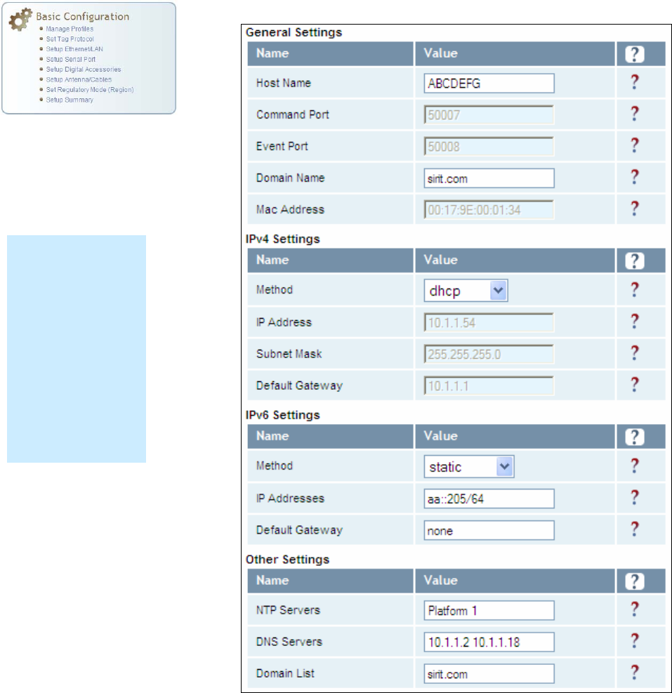
1 2 3 4 5
6
7 8 9
Reader Configuration Tool
IDentity 4100 User Guide
47
Setup Ethernet/LAN
The Setup Ethernet/LAN page allows you to configure the network interface
of the reader.
NOTE:
Always record the
IP, Mac, subnet,
and default
gateway addresses
for your readers
and keep this data
in a safe location.
You can use this
data to reconfigure
the network in the
event of application
failure or data loss.
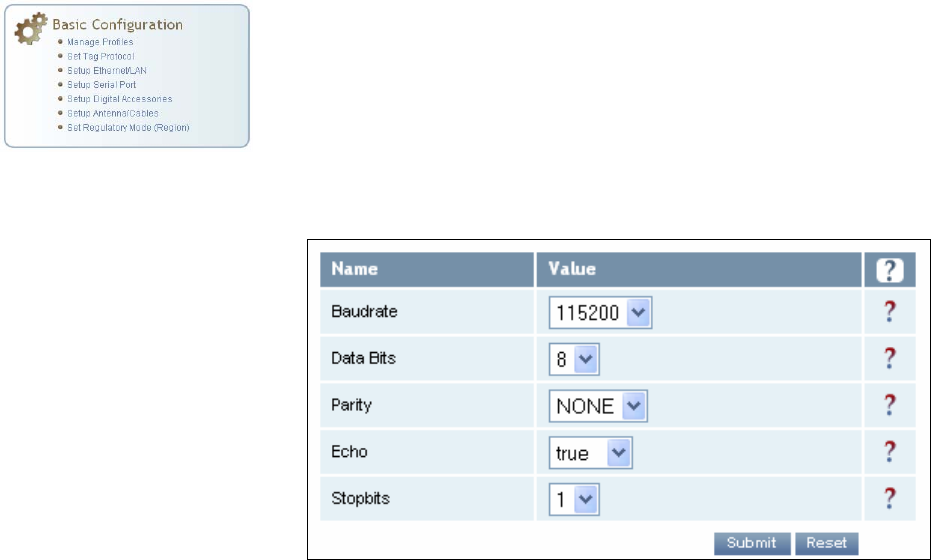
1 2 3 4 5
6
7 8 9
Reader Configuration Tool
48
IDentity 4100 User Guide
General Settings
allow you to specify the host and domain name of the
reader. The Command and Event Ports are also shown and are read-only.
You can also select your domain name in this window.
IPv4/IPv6 Settings
allow you to configure the reader’s IP address. If the
reader is to automatically acquire its IP address, subnet mask and default
gateway from a DHCP server, select
Enable DHCP
. To manually specify this
information, deselect
Enable DHCP
and fill in the desired IP address,
subnet mask and default gateway.
Other Settings
allow you to configure the NTP servers the reader can
contact to obtain the current time, DNS servers the reader can contact for
domain name resolution, and the Domain list to resolve names to IP
addresses.
Enter all the required information and press
Submit
.
Setup Serial Port
The Setup Serial Port function allows you to configure the serial port
parameters. These parameters include:
h Baud rate
h Data bits
h Parity
h Echo
h Stop bits
Use the pull-down menus to select a value and press
Submit
to update the
reader.
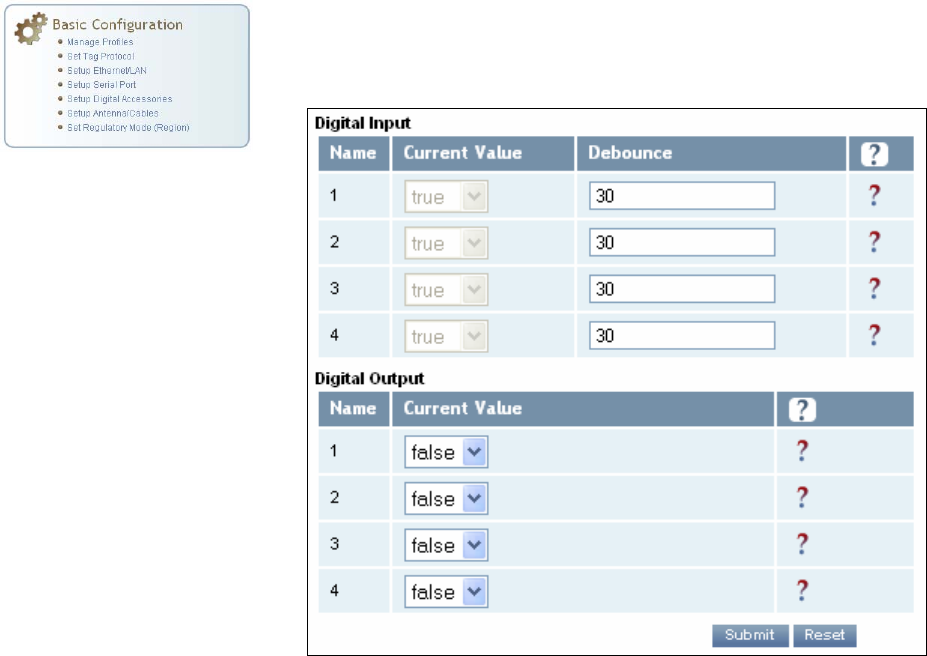
1 2 3 4 5
6
7 8 9
Reader Configuration Tool
IDentity 4100 User Guide
49
Setup Digital Accessories
The Setup Digital Accessories function allows you to configure the Digital
Inputs and Outputs on the reader.
Digital Input
The status of the four digital input values (1–4) can be seen in this window.
The
Current Value
is not configurable and is shown as
true
or
false
. The
Debounce value can be set and is in milliseconds.
Digital Output
The output value for each digital output can be set to true or false. Press
the
Submit
button to send the appropriate commands to the reader to
update the digital inputs and outputs.
Refer to the IDentity 4100 Protocol Reference Guide for more information
on configuring the digital inputs and outputs.
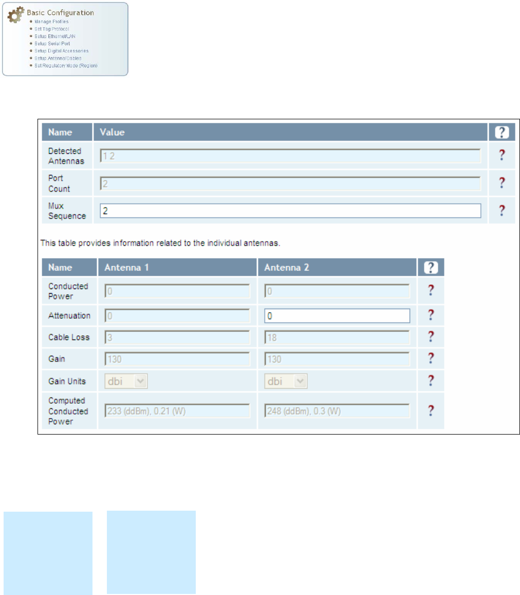
1 2 3 4 5
6
7 8 9
Reader Configuration Tool
50
IDentity 4100 User Guide
Setup Antenna/Cables
This page allows you to configure the properties of the reader’s antenna
configuration. For detailed description of each of the antenna and cable
variables, refer to Antenna Configuration in Chapter 4 – Reader Behavior of
the IDentity 4100 Protocol Reference Guide.
Enter the appropriate values for each antenna parameter and press the
Submit
button to update the antenna and cable configuration.
Antenna Setup
The reader is
configured at the
factory to operate
with specific
antennas.
Antenna Gain
Antenna gain may
differ, depending
on the specific
regulatory region.
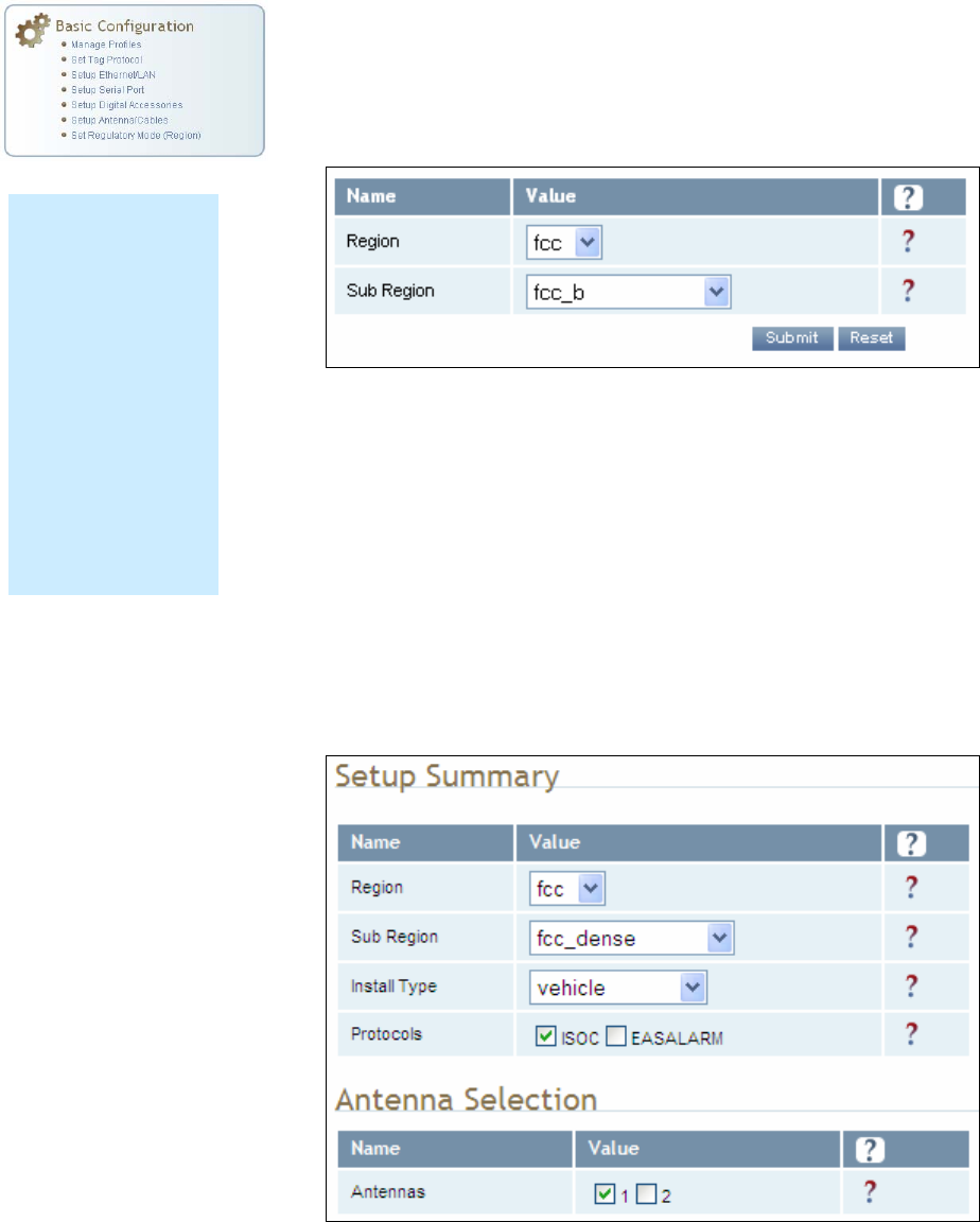
1 2 3 4 5
6
7 8 9
Reader Configuration Tool
IDentity 4100 User Guide
51
Set Regulatory Mode (Region)
This page allows the user to configure the reader to meet the regulatory
requirements for the geographic region where the reader is deployed. The
sub-region sets the secondary regulatory mode for the geographic region
where the reader is deployed.
For detailed information on each of these parameters, refer to the
IDentity 4100 Protocol Reference Guide. Descriptions are provided in the
setup.region and setup.sub_region configuration variable
sections.
Setup Summary
This page allows you to quickly setup the basic operational parameters of
the reader.
Region Selection
The reader is
configured at the
factory to operate
within a specific
regulatory region. As
a result your region
selections may be
different from those
shown in this
manual.
Note that Region
Selection is not user
configurable.
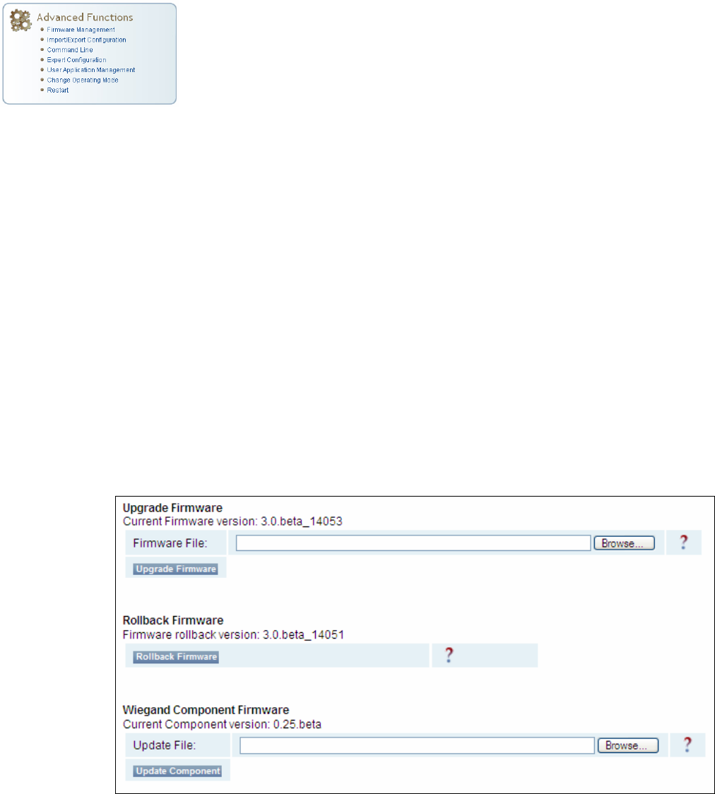
1 2 3 4 5
6
7 8 9
Reader Configuration Tool
52
IDentity 4100 User Guide
Advanced Functions
With the Advanced Functions you can perform the following:
h Firmware Management
h Import/Export Configuration
h Command Line operations
h Expert Configuration
h User Application Management
h Change Operating Mode
h Restart
h View and edit the Wiegand Translation Table
Firmware Management
This page allows you to perform the following:
h Read the current reader firmware version
h Upgrade the reader firmware files
h Rollback to the previous reader firmware version
h Upgrade Wiegand component firmware files (note you can not rollback
the Wiegand firmware)
Enter the name of the Sirit provided firmware file in the
Firmware File
field.
Use the
Browse
button to help locate the file.
The
Rollback Firmware
button will roll back the reader firmware to the
previous version.
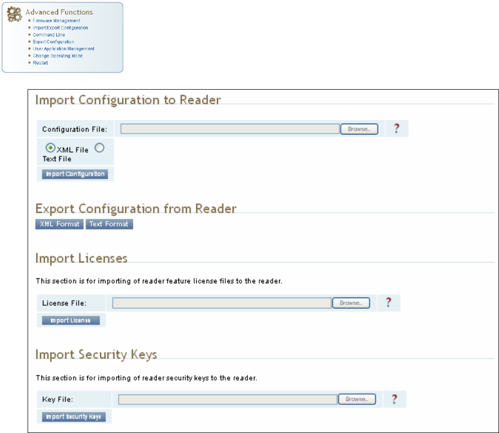
1 2 3 4 5
6
7 8 9
Reader Configuration Tool
IDentity 4100 User Guide
53
Import/Export Configuration
This page allows you to transfer reader configurations, license files, security
keys, and Wiegand translation tables to or from your host computer. This is
useful for configuring a reader to a known state.
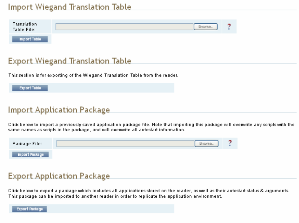
1 2 3 4 5
6
7 8 9
Reader Configuration Tool
54
IDentity 4100 User Guide
Import Configuration to Reader
Enter the name of a saved configuration file in the
Configuration file
field.
Select the
XML File
option and press the
Transfer Configuration to Reader
button to send the profile to the reader.
Export Configuration from Reader
This function is used to export the current reader settings for later
uploading. Press the
XML Format
button to view the XML file in the browser.
Save this file to your computer if you wish retain it for future.
If you wish to view the current configuration parameters for a reader, press
Text Format
button.
1 2 3 4 5
6
7 8 9
Reader Configuration Tool
IDentity 4100 User Guide
55
Import Licenses
This function is used to import a feature license file. Navigate to the license
file and press
Import License
to load the file into the reader.
Import Security Keys
This function is used to import reader security keys to the reader. Navigate
to the key file and press
Import Security Keys
to load the file into the
reader.
Export Security Keys
This function is used to export reader security keys from the reader. Enter
the commissioning password and the mac address file containing a list of
readers (each number followed by a carriage return) to allow import of these
keys. Navigate to the mac address file and press
Export Security Keys
to
load the file into the reader.
Import Wiegand Translation Table
This function is used to import a Wiegand translation table to the reader.
The file will typically have a .csv extension.
Export Wiegand Translation Table
This function is used to export a Wiegand translation table from the reader.
The file extension will default to .csv.
Import Application Package
This function is used to import a set of user applications, along with each
application's arguments and autostart status.
Export Application Package
This function is used to export the user applications, along with each
application's arguments and autostart status.
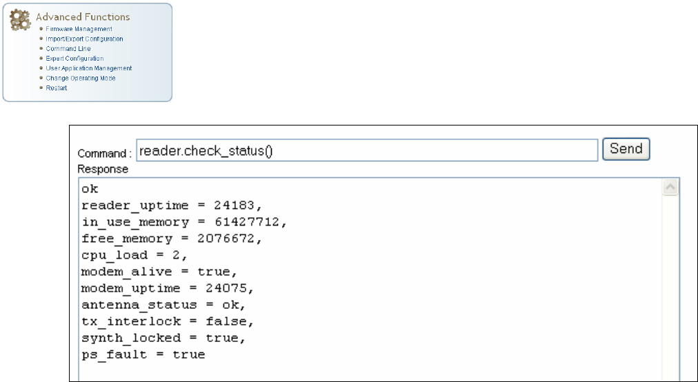
1 2 3 4 5
6
7 8 9
Reader Configuration Tool
56
IDentity 4100 User Guide
Command Line
This page allows you to directly enter reader commands from your web
browser.To directly enter commands from the Command Line Interface
(CLI), refer to the IDentity 4100 Protocol Reference Guide.
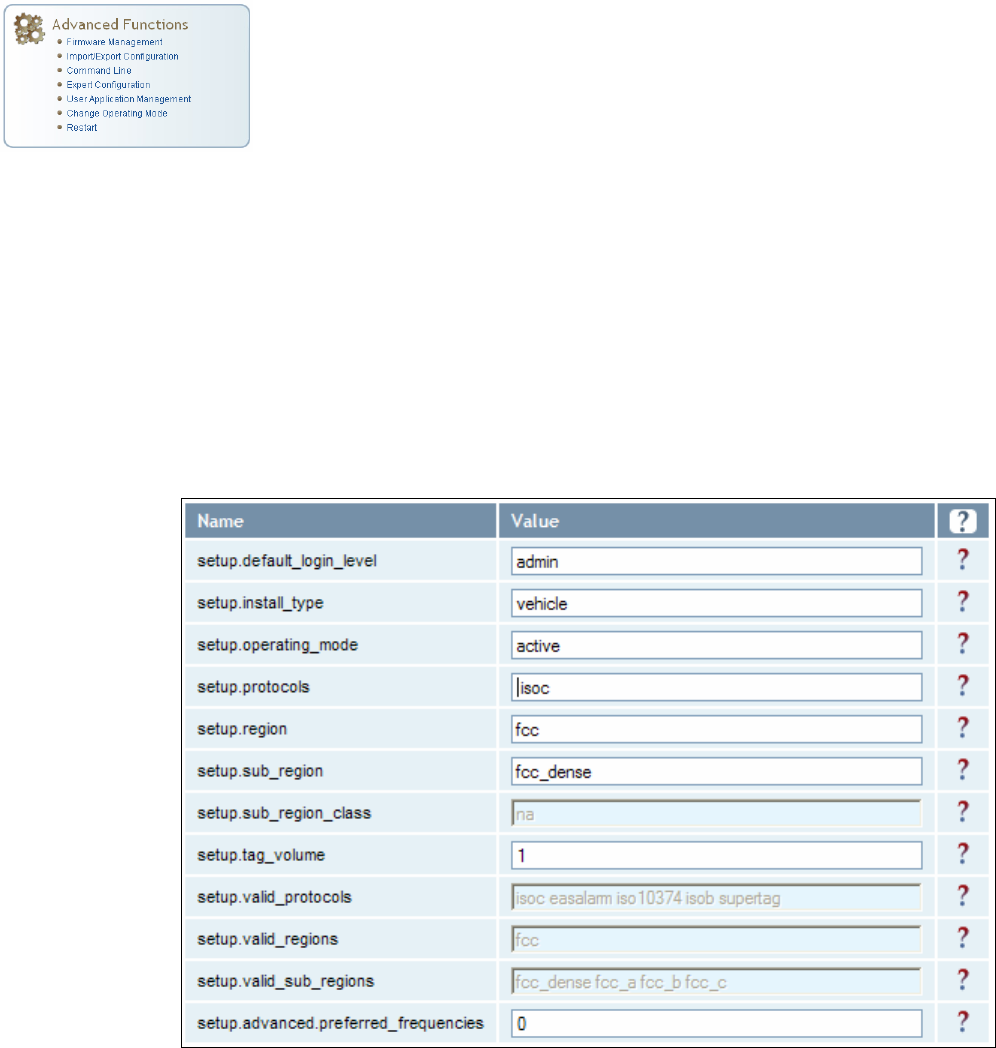
1 2 3 4 5
6
7 8 9
Reader Configuration Tool
IDentity 4100 User Guide
57
Expert Configuration
The Expert Configuration functions allow you to configure low-level functions
within the reader. These functions should only be accessed by expert users.
Expert configurations include:
h Setup
h Tag
h Version
h Information
h Communication
h Antennas
h Digital I/O
h Modem
Expert Configuration – Setup
This page allows you to set the basic operating parameters of the reader
including region, sub region, mode, and active protocols. You can also view
the valid protocols and regions.
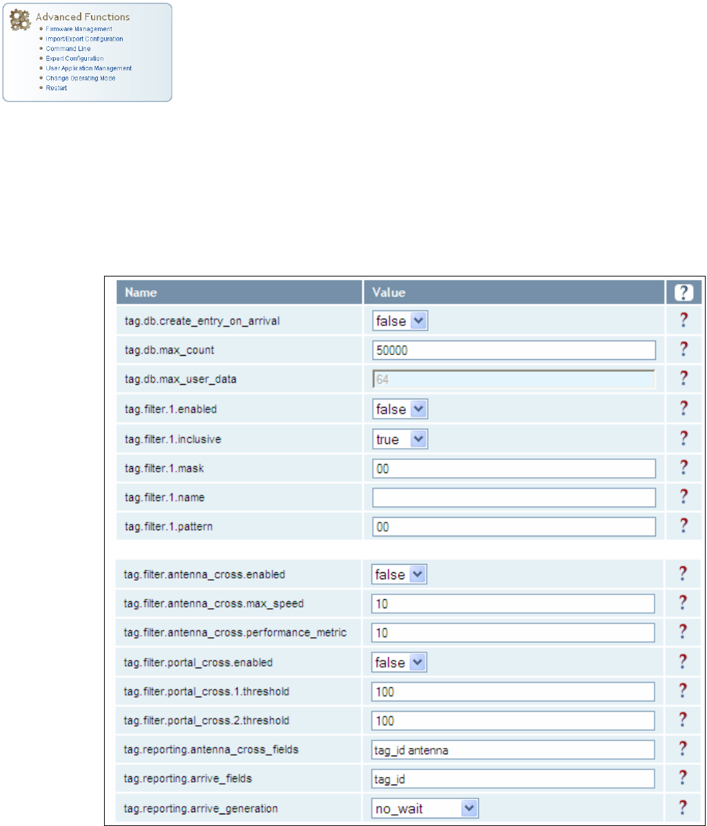
1 2 3 4 5
6
7 8 9
Reader Configuration Tool
58
IDentity 4100 User Guide
Expert Configuration – Tag
This page allows you to configure how the reader reports tags.
The IDentity 4100 supports the ability to filter tags. Filtering tags means to
eliminate tags from being reported based on the conditions specified in the
filter configuration variables. The reader supports eight filters and each
filter is specified by the following configuration variables:
h
name
– Name given to the tag filter
h
pattern
– Pattern (as an array of hex bytes) for the tag filter
h
enabled
– Enables or disables the filter.
h
inclusive
– Indicates to either include tags that match (Inclusive) or
include tags that do not match (Exclusive) the tag filter.
h
mask
– Mask (as an array of hex bytes) for the tag filter.
The following figure shows only a small sample of the available tag
configuration variables.
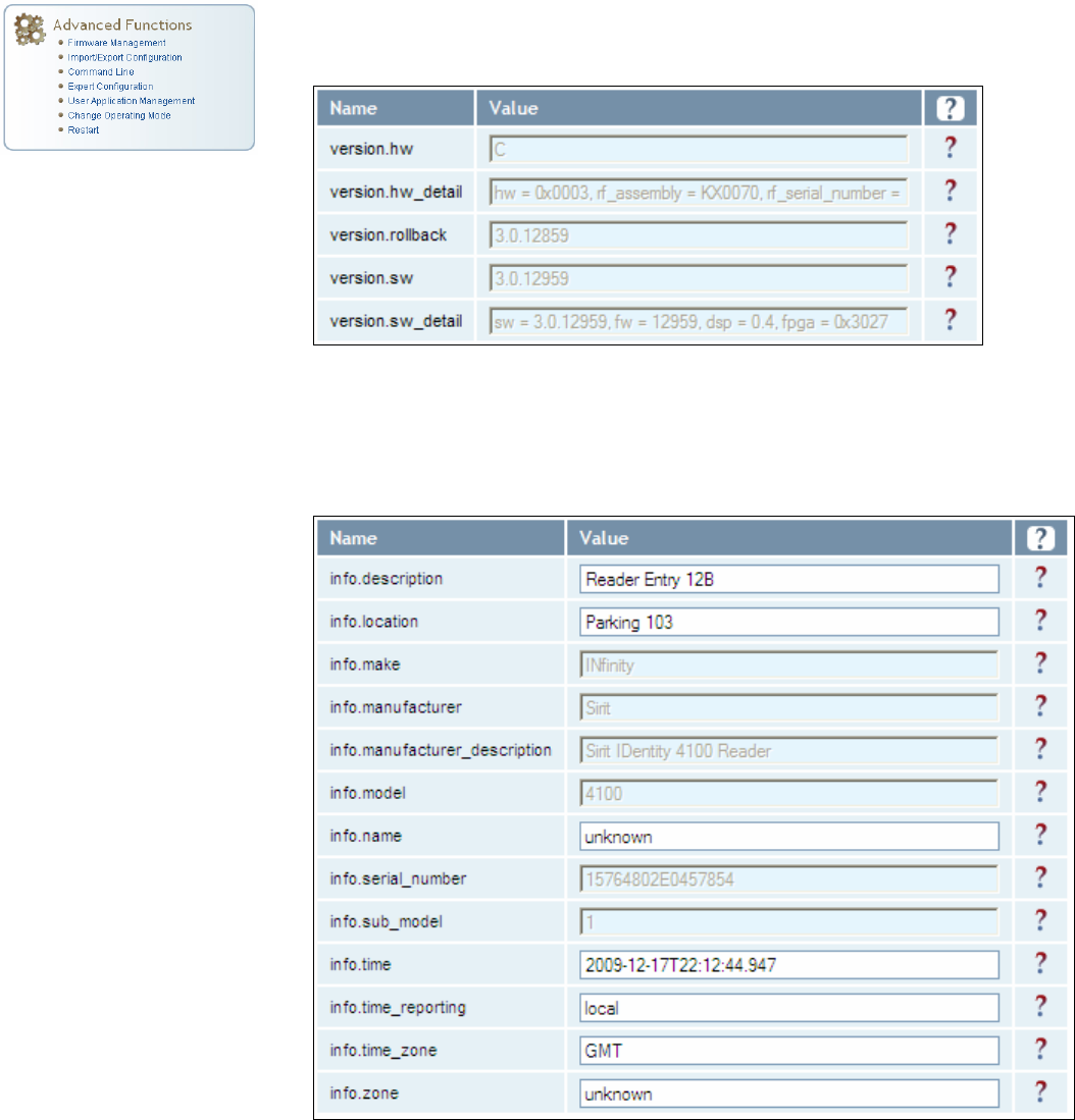
1 2 3 4 5
6
7 8 9
Reader Configuration Tool
IDentity 4100 User Guide
59
Expert Configuration – Version
This page displays the version of reader hardware and reader software
within the reader. The version numbers are read-only and will be needed if
you contact Sirit for technical support.
Expert Configuration – Information
This page allows you to customize the reader’s identity. You can assign
each reader a name, description, location, and zone. You can also set how
the reader reports timestamps.
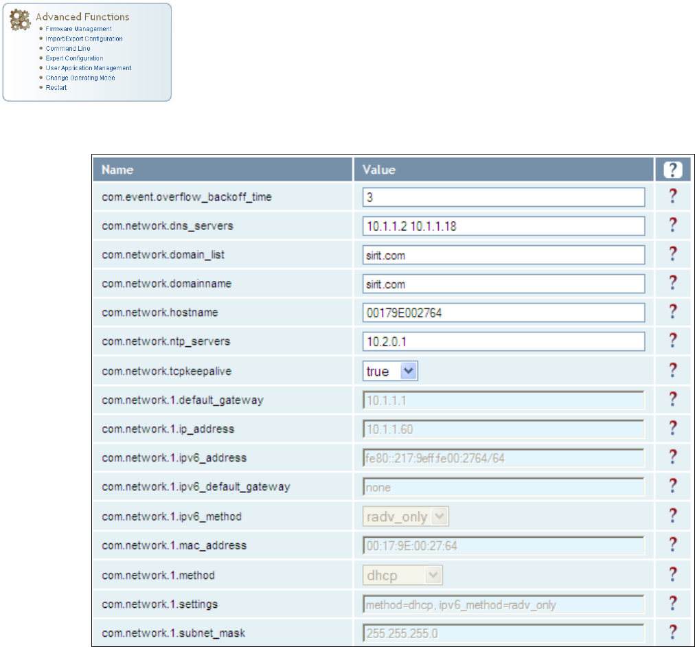
1 2 3 4 5
6
7 8 9
Reader Configuration Tool
60
IDentity 4100 User Guide
Expert Configuration – Communication
This page allows you to customize the reader’s communication parameters.
Refer to the Setup Ethernet/LAN and Setup Serial Port sections for
additional information.
The following figure shows only a small sample of the available reader
communication variables.
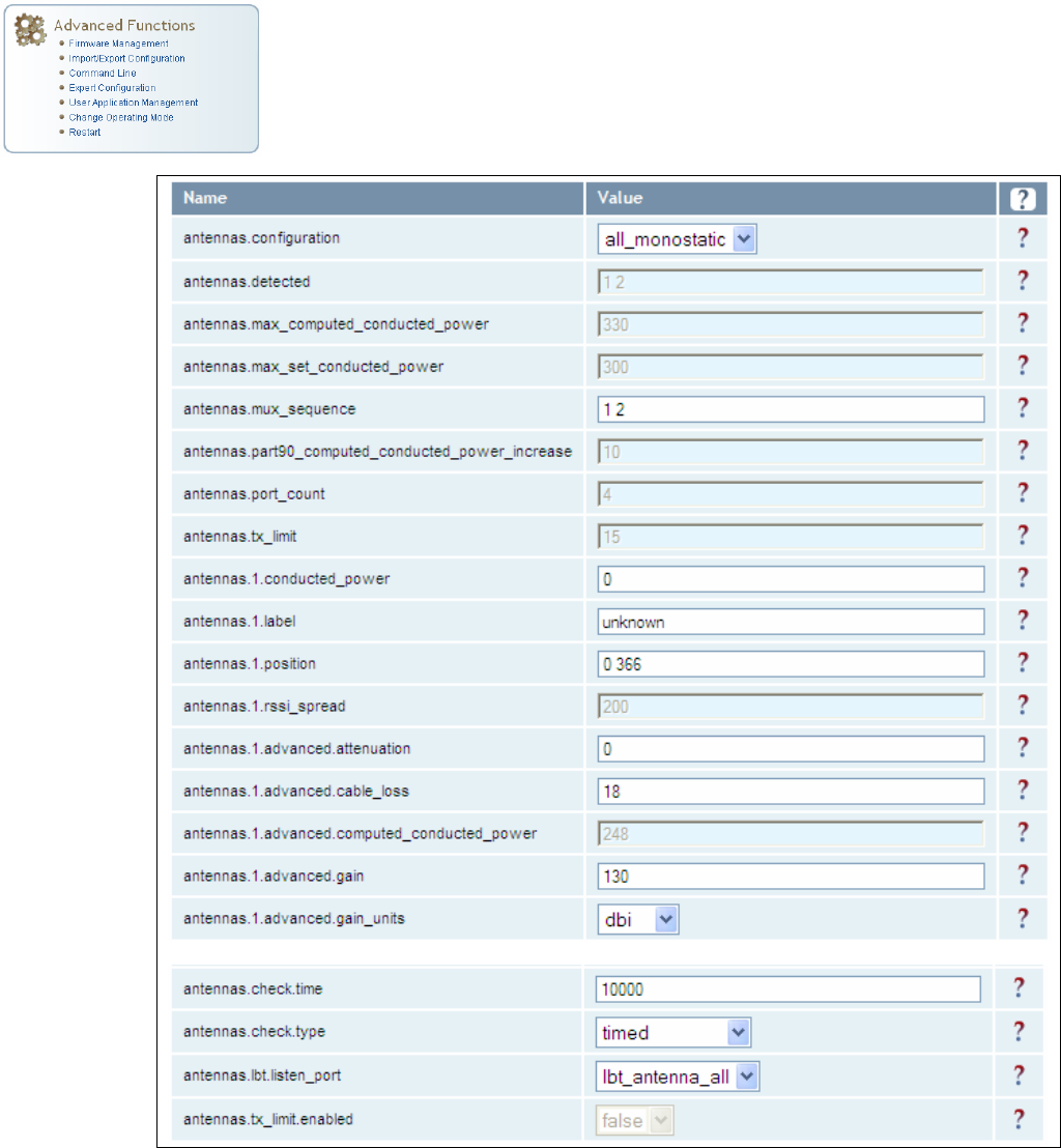
1 2 3 4 5
6
7 8 9
Reader Configuration Tool
IDentity 4100 User Guide
61
Expert Configuration – Antennas
This page allows you to configure the properties of the reader’s antenna
configuration. For detailed description of each of the antenna and cable
variables, refer to the Antenna Configuration section in Chapter 4 – Reader
Behavior of the IDentity 4100 Protocol Reference Guide.
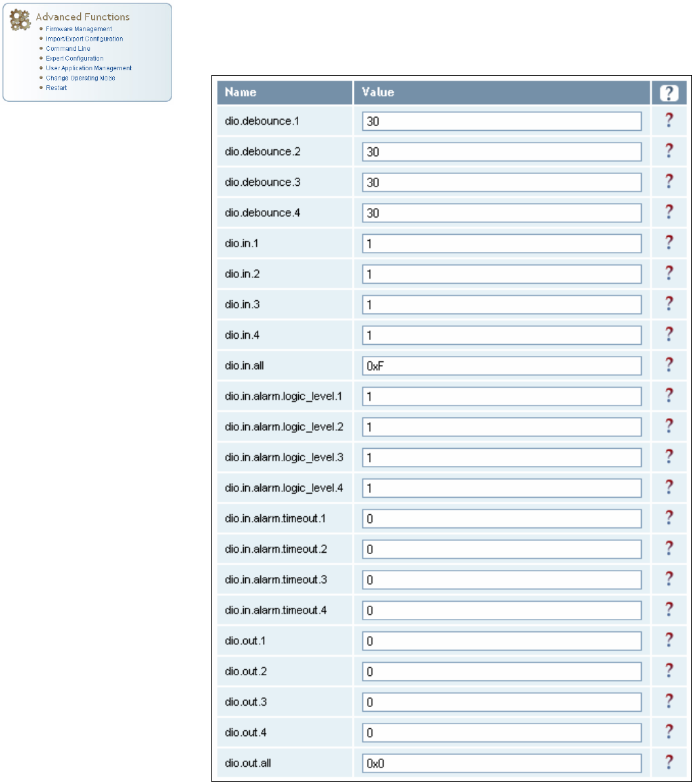
1 2 3 4 5
6
7 8 9
Reader Configuration Tool
62
IDentity 4100 User Guide
Expert Configuration – Digital I/O
This page allows you to configure the digital inputs and output behavior. You
can set the digital input debounce time (in milliseconds), as well as the
input and output pin values. Refer to the IDentity 4100 Protocol Reference
Guide for detailed information on each of these variables.
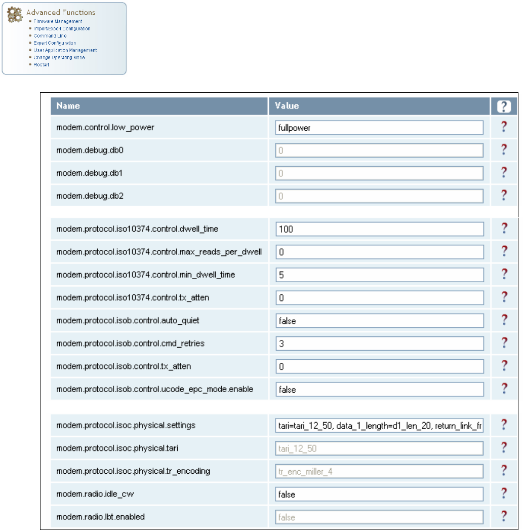
1 2 3 4 5
6
7 8 9
Reader Configuration Tool
IDentity 4100 User Guide
63
Expert Configuration – Modem
This page allows you to set the reader’s modem control variables. These
variables control functions such as EPC link, modulation depth, return link
frequency, and others. Refer to the IDentity 4100 Protocol Reference Guide
for detailed information on each of these variables.
The following figure shows only a small sample of the available modem
configuration variables.
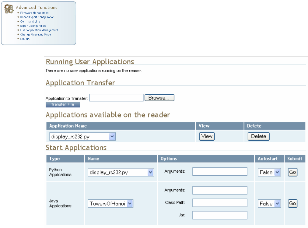
1 2 3 4 5
6
7 8 9
Reader Configuration Tool
64
IDentity 4100 User Guide
User Application Management
This page lists any user applications currently available on the reader and if
any applications are running. This page also allows you to upload scripts to
the reader.
h
Running User Applications – Lists any user applications currently
running on the reader. The application name, process ID, configuration,
and status are provided. Controls are provided to view the application
file and stop the application.
h
Application Transfer – This function allows you to load custom user
applications onto the reader.
h
Applications available on the reader – This function allows you to view a
list of all user applications stored on the reader. Controls are provided
to view the application and delete it from the reader.
h
Start Applications – This function allows you to start Python and Java
applications.
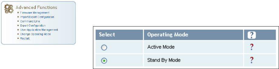
1 2 3 4 5
6
7 8 9
Reader Configuration Tool
IDentity 4100 User Guide
65
Change Operating Mode
This page allows you to configure the operational mode of the reader.
The reader supports the following operational modes:
h
Active Mode - Reader is continuously attempting to singulate tags and
automatically reports any singulated tag via an asynchronous event
notification on the event channel.
h
Stand By Mode - Reader is not transmitting any energy, unless
processing a tag related command. The RF transmitter is enabled at the
beginning of the command processing, any protocol operations required
for the command are performed, and then the RF transmitter is turned
back off.
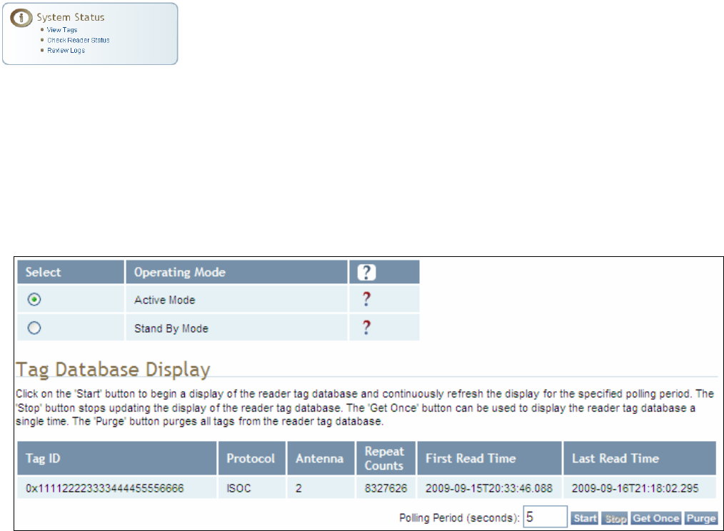
1 2 3 4 5
6
7 8 9
Reader Configuration Tool
66
IDentity 4100 User Guide
View Tags
All tags read by the reader are stored in a database on the reader. This
page allows you to view the tags in the database as well as change the
current Operating Mode (Active or Stand By).
Press Start to begin displaying the tag database. This page is automatically
refreshed every five seconds. Press Get Once to update the database one
time (refresh is off). Press Purge to purge all tags from the database.
Clicking on any of the column headers will sort the tag database display by
that parameter.
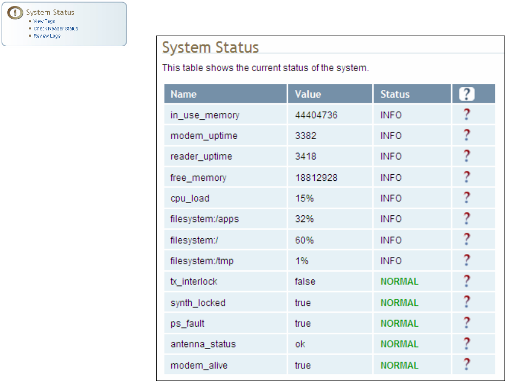
1 2 3 4 5
6
7 8 9
Reader Configuration Tool
IDentity 4100 User Guide
67
Check Reader Status
This page allows you to view the reader status. This information can be
used by Sirit Technical Support to verify reader operation.
In addition, you can also view the status of the following:
h Services such as discovery, sshd, and console.
h Licensed Features such as Antenna Crossing, Stray Tag Elimination, and
tag Phase Reporting
h Components such as the Wiegand Interface Module.
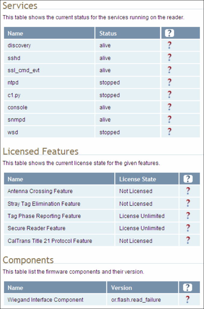
1 2 3 4 5
6
7 8 9
Reader Configuration Tool
68
IDentity 4100 User Guide
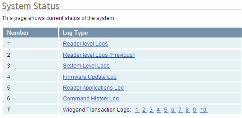
1 2 3 4 5
6
7 8 9
Reader Configuration Tool
IDentity 4100 User Guide
69
Review Logs
This page allows you to view the reader logs. These logs can be used by Sirit
Technical Support to verify reader operation. The reader logs include:
h
Reader level Logs
– System level reader operation
h
System Level Logs
– Linux logs
h
Firmware Update Log
– System level
h
Reader Applications Log
– User application logs
h
Command History Log
– Recent commands sent to the reader
h
Wiegand Translation Logs
– Logs associated with the translation
tables for the Wiegand Interface Module
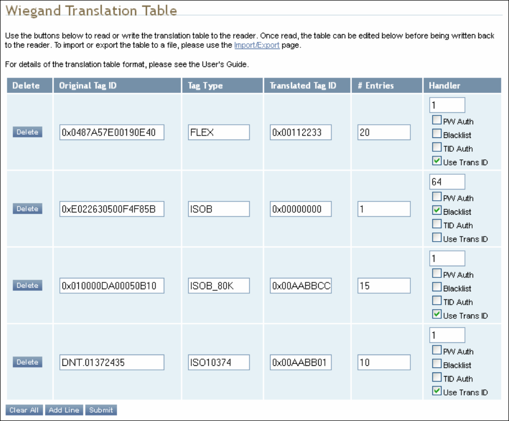
1 2 3 4 5
6
7 8 9
Reader Configuration Tool
70
IDentity 4100 User Guide
Wiegand Translation Table
This page allows you to view and edit the Translation Table used for
Wiegand operation and also for the Standalone Access Control script.
The table is only displayed when the Wiegand component is active (when
com.wiegand.enable is set to true). Buttons allow you to edit existing
translation table entries, add new entries, or delete existing entries. You
must click
Submit
to save table changes to the reader.

1 2 3 4 5 6
7
8 9
Configuring Digital I/O
IDentity 4100 User Guide
71
Configuring Digital Inputs and Outputs
Digital input and output signals are provided via the bulkhead connector.
Refer to Chapter 8 – Specifications for the connector pin out. Refer to
Figure 5 for in this chapter for an example input/output circuit.
This chapter describes how to configure the digital inputs and outputs.
Digital Inputs
The digital inputs (DIN1 – DIN4) can be used as general purpose inputs or
to trigger the reader for tag reading. Unused or open digital inputs are
floating inside the reader.
To activate the input, pull it low (0 VDC) with an external device or
connection to ground that can sink 2.5 mA. No voltage higher than +24 VDC
or lower than 0 VDC should ever be connected to the input. See Figure 5 for
an example of a typical motion sensor installed as a tag read trigger device.
Digital Outputs
The digital outputs (DOUT1 – DOUT4) can be used as general purpose
outputs, to indicate tag reading activity, or to indicate the reader is
transmitting (RF On). Digital outputs can be pulled high.
No voltage higher than +40 VDC or lower than 0 VDC should ever be
connected to a digital output. The reader activates the output by pulling it
low (0 VDC) and can sink current such that power dissipation is ≤ 1 W.
Digital I/O Monitoring and Control Scripts
Several digital I/O monitoring and control scripts are provided with the
reader to allow you to monitor the digital I/Os and take specific actions.
These Python application scripts can be used as is or modified to suit your
particular application. For detailed information on loading Python scripts,
refer to Chapter 5 – Embedded Reader Applications of the IDentity 4100
Protocol Reference Guide.
1 2 3 4 5 6
7
8 9
Configuring Digital I/O
72
IDentity 4100 User Guide
scan_trigger.py
This routine monitors the state of the digital input pin specified as the input
parameter. If the state of the pin is low, the operating mode is set to standby. If
the I/O pin state changes to high, the operating mode is set to polled.
Inputs: <pin> – (optional) Input pin number (1–4). Default is digital in 1.
<trigger logic level> –(optional) 0 or 1. Default is trigger on 1.
Examples:
scan_trigger.py Monitors digital input pin 1
scan_trigger.py 1 Monitors digital input pin 1
scan_trigger.py 4 Monitors digital input pin 4
scan_trigger.py 3 0 Monitors digital input pin 3, trigger on 0
scan_trigger_timer.py
This routine monitors the I/O pin. When the pen goes high, the timer is started
and the operating mode is set to polled. While the timer is running, I/O pin state
changes are ignored. When the timer expires, the operating mode is set to
standby. The minimum value for the timer is 10 milliseconds (ms).
Inputs: <pin> – (optional) Output pin number (1–4). Default is output 1.
<time> – (optional) Time, in ms for timer to run. Default is 1000 ms.
<trigger logic level> –(optional) 0 or 1. Default is trigger on 1.
Examples:
scan_trigger_timer.py Monitors input 1, timer 1000 ms,
trigger on 1
scan_trigger_timer.py 2 Monitors input 2, timer 1000 ms,
trigger on 1
scan_trigger_timer.py 4 2000 Monitors input 4, timer 2000 ms,
trigger on 1
scan_trigger_timer.py 3 4000 0 Monitors digital input 3, timer 4000 ms,
trigger on 0
1 2 3 4 5 6
7
8 9
Configuring Digital I/O
IDentity 4100 User Guide
73
standalone_acs.py
This routine implements a simple standalone access control system. It is
described in the Stand Alone Reader Operation Application Note.
signal_read.py
This routine will activate a digital output if a tag is successfully read. The
optional output pin number can be specified on the command line. If not
specified, output pin 1 is selected and a default value of 1000 milliseconds is
used. The output will remain high for n ms, where n is either the default of 1000
ms, or the value supplied on the command line. Minimum value for n is 10 ms.
Inputs: <pin> – (optional) Output pin number (1–4). Default is output 1.
<time> – (optional) Time, in ms, to keep the output high. Default is
1000 ms (1 sec).
<logic level> – (optional) Logic level for digital out On. 0 or 1. Default
is 1 (On).
Examples:
signal_read.py Turns on output 1 for 1000 ms on tag reads
signal_read.py 2 Turns on output 2 for 1000 ms on tag reads
signal_read.py 1 5000 Turns on output 1 for 5000 ms on tag reads
signal_read.py 1 500 Turns on output 1 for 500 ms on tag reads
signal_read.py 1 800 0 Turns on digital output 1,logic level 0, for
800 ms on tag reads
1 2 3 4 5 6
7
8 9
Configuring Digital I/O
74
IDentity 4100 User Guide
signal_read_crc_error.py
This routine will turn on a digital output if a tag read CRC error is detected. The
output pin number can be specified on the command line. If not specified,
output pin 1 is used. The output pin will remain high for n ms, where n is either
the default of 1000 ms or the value supplied on the command line. Minimum
value for n is 10 ms.
Inputs: <pin> – (optional) Output pin number (1–4). Default is output 1.
<time> – (optional) Time, in ms, to keep the output high. Default is
1000 ms.
<logic level> – (optional) Logic level for digital out On. 0 or 1.
Default is 1 (On).
Examples:
signal_read_crc_error.py
Turns on output 1, logic level 1 for on
for 1000 ms on tag read CRC error.
signal_read_crc_error.py 2
Turns on output 2, logic level 1 for on
for 1000 ms on tag read CRC error.
signal_read_crc_error.py 1 5000
Turns on output 1, logic level 1 for
on for 5000 ms on tag read CRC
error.
signal_read_crc_error.py 1 500
Turns on output 1, logic level 1 for
on for 500 ms on tag read CRC
error.
signal_read_crc_error.py 1 800 0
Turns on output 1, logic level 0 for
on, for 800 ms on tag CRC error.
rf_mon.py
This routine will monitor the state of the transmitter. If the transmitter is on, it
sets the appropriate output pin high. If low, it sets the output pin low.
Inputs: <pin> – (optional) Output pin number (1–4). Default is output 1.
<logic level> – (optional) Logic level for digital out On. 0 or 1.
Default is 1 (On).
Examples:
rf_mon.py Monitors RF status, set/clear output 1 on change, logic
level 1 for on
rf_mon.py 1 Monitors RF status, set/clear output 1 on change, logic
level 1 for on
rf_mon.py 2 Monitors RF status, set/clear output 2 on change, logic
level 1 for on
rf_mon.py 3 0 Monitors RF status, set/clear output 3 on change, logic
level 0 for on
1 2 3 4 5 6
7
8 9
Configuring Digital I/O
IDentity 4100 User Guide
75
Digital Input Alarm Generation
The IDentity 4100 can be configured to generate an alarm when a digital
input is disconnected or sensor failure is detected. The alarm is triggered
when the signal level on the digital input stays in the specified state longer
than the specified alarm timeout. This behavior can be configured
independently for each digital input.
The configuration variable
dio.in.alarm.logic_level.<N>
(where <N> is
1,2,3,4) sets whether the alarm is coupled to a input logic level of 0 (low) or
1 (high).
The configuration variable
dio.in.alarm.timeout.<N>
(where <N> is 1,2,3,4)
sets the amount of time, in seconds, to wait for a signal state change. A
value of 0 (default) disables alarm generation.
The digital input logic level is used along with the corresponding digital input
pin timeout value to determine if an alarm (in the form of an event) should
be generated. If a timeout value is set, the input pin is monitored. If the
input pin value does not change during the timeout period AND the input
pin value matches the alarm logic level, the event
event.dio.in.alarm.timeout.n
(where n is the pin number) is generated. This
alarm event generation can be helpful in alerting to the loss of digital inputs
to the reader.
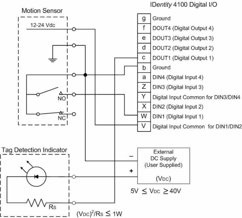
1 2 3 4 5 6
7
8 9
Configuring Digital I/O
76
IDentity 4100 User Guide
Digital I/O Hardware Connection
Figure 5 shows a typical sensor/indicator connection to the digital I/Os.
Figure 5 Example Motion Detector and Indicator connected to the Digital I/O
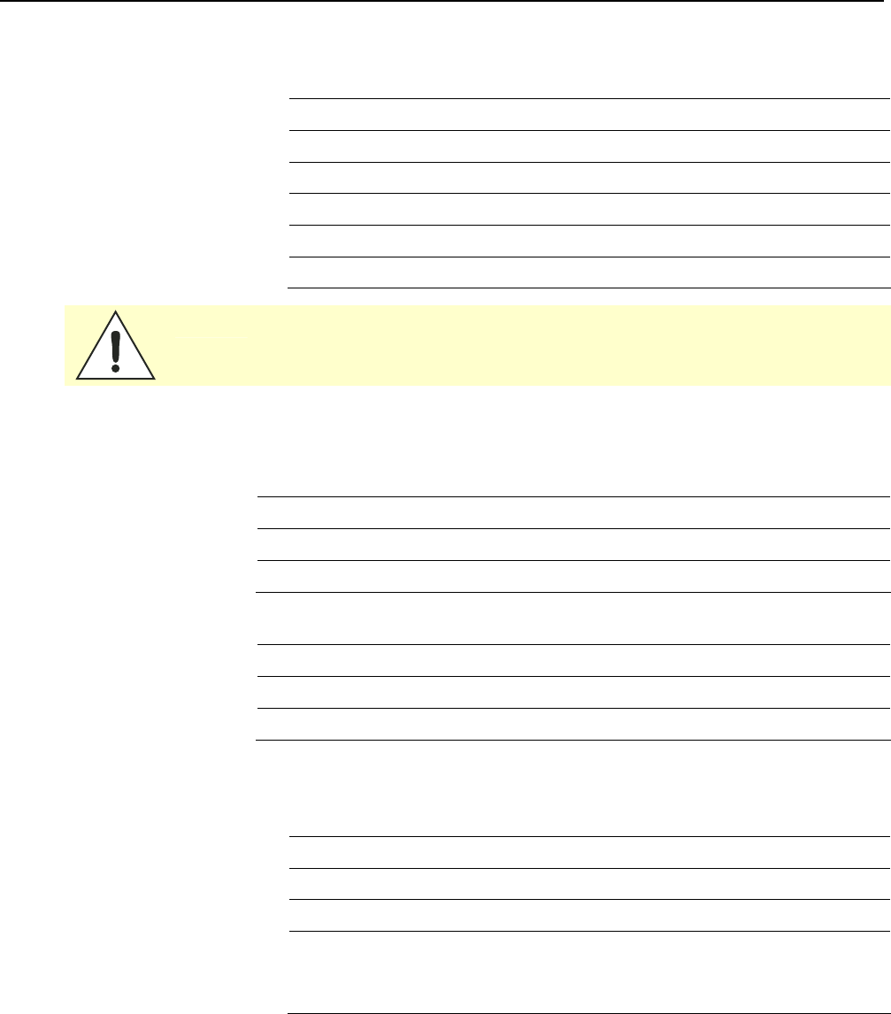
1 2 3 4 5 6 7
8
9
Specifications
IDentity 4100 User Guide
77
Specifications
Reader Specifications (General)
Dimensions 12.0 x 12.0 x 4.1 in (305 x 305 x 105 mm)
Weight 4.8 kg (10.5 lbs)
Frequency Range 860–960 MHz (Factory configured for specific region)
Connectors RS-232, Digital I/O, Ethernet LAN
Input Voltage 24 VDC, 60 W
Input Current 2.5 A maximum at 24 VDC
Caution:
The Sirit supplied power cable is only rated at 24V. Input power less than 24V
while using Sirit supplied cables may result in cable and/or reader damage.
Reader Ordering Information
FCC Part 15 and Industry Canada RSS 210
Reader Model Ordering Part # Description
ID4100-001 ID4100-001 ID4100 without Weigand Interface
ID4100-001 ID4100-002 ID4100 with Weigand Interface
FCC Part 90 and Industry Canada RSS 137
Reader Model Ordering Part # Description
ID4100-90 ID4100-901 ID4100 without Weigand Interface
ID4100-90 ID4100-902 ID4100 with Weigand Interface
Reader Specifications – FCC Part 15, Industry Canada
RSS 210
(Model ID4100-001)
Frequency Range
FCC Part 15 902–928 MHz
RF Power 10 mW – 0.871 W conducted (10 – 29 dBm)
Power
Consumption
13 W (typical while idle)
32 W (typical at 29 dBm conducted output power)
38 W (maximum at 29 dBm conducted output power)
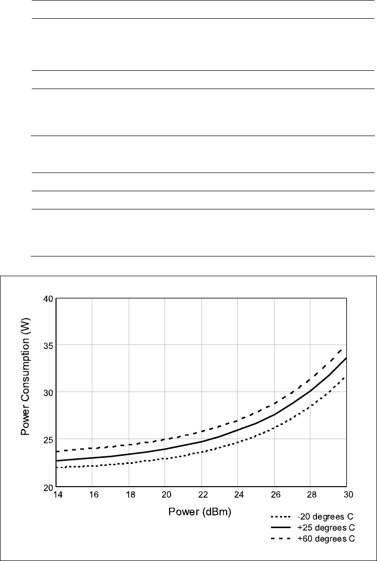
1 2 3 4 5 6 7
8
9
Specifications
78
IDentity 4100 User Guide
Reader Specifications – FCC Part 90, Industry Canada
RSS 137
(Model ID4100-90)
Frequency Range
FCC Part 90 911.250, 911.750, 912.250, 912.750, 913.250,
913750, 914.250, 914.750, 915.250, 915.750,
916.250, 916.750, 917.250, 917.750, 918.250,
918.750, 919.250, 919.750, 920.250 MHz
RF Power 10 mW – 2 W conducted (10 – 33 dBm)
Power
Consumption
13 W (typical while idle)
32 W (typical at 29 dBm conducted output power)
38 W (maximum at 29 dBm conducted output power)
Reader Specifications – ETSI
(ID4100-001-ETSI and -002-ETSI)
Frequency Range 865–868 MHz (Factory configured for specific region)
RF Power 10 mW – 560 mW conducted (10 – 27.5 dBm)
Power
Consumption
13 W (typical while idle)
30 W (typical at 27.5 dBm conducted output power)
36 W (maximum at 27.5 dBm conducted output power)
Figure 6
Typical Power Consumption versus Conducted Output Power at 910 MHz

1 2 3 4 5 6 7
8
9
Specifications
IDentity 4100 User Guide
79
Environmental Specifications
Operating Temperature -40 °F to 131 °F (-40 °C to 55 °C)
Storage Temperature -40 °F to 185 °F (-40 °C to 85 °C)
Maximum Shock 1 foot (0.3 meter) drop to any corner
Relative Humidity 100 %, condensing
International Protection
Rating
IP65
Power Supply Specifications
Model Lambda DSP100-24
Input Voltage 90 – 264 VAC,
Input Frequency 47 to 63 Hz
Power 100.8 W
Holdup Time 10 ms (115 VAC)
Output Voltage 24 VDC
Output Current 4.2 A
RS-232 Specifications
Connector DB-9S
Baud rate 1200 - 115200 (Default = 115200)
Parity None
Data bits 8
Stop bits 1
Signals Pin 1 - NC
Pin 2 - TXD
Pin 3 - RXD
Pin 4 - Connected to Pin 6
Pin 5 - GND
Pin 6 - Connected to Pin 4
Pin 7 - CTS
Pin 8 - RTSA
Pin 9 - NC

1 2 3 4 5 6 7
8
9
Specifications
80
IDentity 4100 User Guide
Ethernet LAN Specifications
Connector RJ-45
Ethernet 10/100 BaseT
Indicators Yellow - Indicates link is operational
Green - Indicates network traffic detected.
Signals Pin 1 – TXD+ (Transmit Data +)
Pin 2 – TXD- (Transmit Data -)
Pin 3 – RXD+ (Receive Data +)
Pin 4 – NC
Pin 5 – NC
Pin 6 – RXD- (Receive Data -)
Pin 7 – NC
Pin 8 – NC
Antenna Cable Specifications
Manufacturer Time Microwave Systems
Part No. LMR-400 (replacement for RG-8/9913)
Connector Type RP-TNC
Impedance 50 ohms
Attenuation 3.9 dB/100 ft (12.8 dB/100 m)
Internal Antenna Specifications (FCC)
Type PATCH
Frequency (FCC) 902 – 928 MHz
Polarization Circular
Gain 9.5 dBiC
VSWR, maximum 1.5:1
Input impedance 50 ohm (nominal)
Power Handling 6 W
Size (FCC) 12.0 x 12.0 x 1.4 in (305 x 305 x 36 mm)

1 2 3 4 5 6 7
8
9
Specifications
IDentity 4100 User Guide
81
Internal Antenna Specifications (ETSI)
Type PATCH
Frequency (ETSI) 865 – 868 MHz
Polarization Circular
Gain 9 dBiC
VSWR, maximum 1.3:1
Input impedance 50 ohm (nominal)
Power Handling 6 W
Size (ETSI) 305 x 305 x 36 mm (12 x 12 x 1.4 in)
Battery Specifications (Optional)
Battery Lithium/Manganese Dioxide
Designation ANSI/NEDA 5012LC / IEC-CR1220
Voltage 3 V
Average capacity 40 mAh to a terminal voltage of 2 V

1 2 3 4 5 6 7
8
9
Specifications
82
IDentity 4100 User Guide
External Antenna Specifications (FCC)
Part No. ANTENNA–018-E
Frequency range 902–928 MHz
Antenna type Patch
Impedance 50 Ω, nominal
Gain 9.5 dBic
Beam width (-3 dB) 63°, nominal
Polarization RH circular
F/B ratio -18 dB, typical
Side lobes level -16 dB, typical @ 90°
Power input 37 dBm (5 W)
Return loss -14 dB, minimum
Connector type N type Female (Jack)
Size (height x width x
thickness)
12.0 x 12.0 x 0.98 in (305 x 305 x 25 mm)
Weight 2.65 lbs (1.2 kgs)
Caution:
For Model ID4100-001
This device is designed to operate with a 9.5 dBiC (9.0 dBiC for ETSI) gain internal and
external antenna and conducted power is factory set to 23 dBm (200 mW). When conducted
power is set to 29 dBm (0.871 W), the antenna gain cannot exceed 9.5 dBiC. Antenna
having a higher gain is strictly prohibited per FCC and Industry Canada regulations when
utilizing maximum power. Power into the antenna must decreased to compensate for any
increased antenna gain. The required antenna impedance is 50 ohms.
To reduce potential radio interference to other users, the antenna type and its gain should
be so chosen that the equivalent isotropically radiated power (EIRP) is not more than that
required for successful communication.
The installer of this radio equipment must ensure that the antenna is located or pointed
such that it does not emit an RF field in excess of Health Canada limits for the general
population; consult Safety Code 6, obtainable from Health Canada’s website.

1 2 3 4 5 6 7
8
9
Specifications
IDentity 4100 User Guide
83
External Antenna Specifications (ETSI)
Part No. ANTENNA–019-E
Frequency range 865–870 MHz
Antenna type Patch
Impedance 50 Ω, nominal
Gain 9.0 dBic
Beam width (-3 dB) 63°, nominal
Polarization RH circular
F/B ratio -18 dB, typical
Side lobes level -16 dB, typical @ 90°
Power input 37 dBm (5 W)
Return loss -17 dB, minimum
Connector type N type Female (Jack)
Size (height x width x
thickness)
12.0 x 12.0 x 0.98 in (305 x 305 x 25 mm)
Weight 2.65 lbs (1.2 kgs)
Site License –
Customer Disclaimer
For Models ID4100-90
Customer (end user) acknowledges that a site license is required for each reader
system location. It is the customer’s responsibility to file for the site license and
submit the appropriate filing payment. Sirit can assist with the completion of
forms. United States filings require completion and submission of FCC Form 601
with Schedule D and H. Canadian filings require completion and submission of
Industry Canada Forms IC2365BB and IC2430BB.
Licence d'Etat-client Avertissement
Client (utilisateur final) reconnaît que le site d'une licence est requise pour
chaque lecteur emplacement du système. Il incombe au client de déposer pour la
licence d'exploitation et soumettre le paiement du dépôt approprié. Sirit peut
aider à la réalisation de formes. Unis dépôts États exigent l'achèvement et la
soumission du formulaire FCC 601 à l'annexe D et H. dépôts canadiennes exigent
l'achèvement et la soumission de Industrie Canada Formulaires IC2365BB et
IC2430BB

1 2 3 4 5 6 7
8
9
Specifications
84
IDentity 4100 User Guide
Caution:
For Models ID4100-90
This equipment complies with FCC Part 90 and Industry Canada.RSS-137 rules.
This device complies with FCC Part 15 and Industry Canada license exempt RSS
standard(s). Operation is subject to the following two conditions: (1) this device
may not cause interference, and (2) this device must accept any interference,
including interference that may cause undesired operation of the device.
Cet appareil est conforme à FCC Partie15 de Industrie Canada RSS standard
exempts de licence (s). Son utilisation est soumise à Les deux conditions
suivantes: (1) cet appareil ne peut pas provoquer d’interférences et (2) cet
appareil doit accepter Toute interférence, y compris les interférences qui peuvent
causer un mauvais fonctionnement du dispositif.
Any changes or modifications not expressly approved by Sirit could void the user’s
authority to operate the equipment.
The professional installer will need to calculate and verify the reader’s power
output allowable based on the antenna (gain) used and cabling (loss) effects.
This value will be used in the user’s submission of their site license application.
The maximum antenna gain plus cable effects for a given output power can be
calculated by:
44.8 dBm (ERP) - Pout
where Pout is the measured RF output power (dBm)
Reader output power is limited to a maximum of 2W under all conditions. When
operating at that power level, the maximum permissible antenna gain is 11.2dBd.
WARNING:
For Models ID4100-001, ID4100-90
FCC Radiation Exposure Statement. The antennas used for this transmitter
must be installed to provide a separation distance of at least 1 meter from all
persons and must not be co-located or operating in conjunction with any other
antenna or transmitter.
This device complies with Health Canada’s Safety Code. The installer of this
device should ensure that RF radiation is not emitted in excess of the Health
Canada’s requirement. Information can be obtained at:
http://www.hc-sc.gc.ca/ewh-semt/pubs/radiation/radio_ guidelignes_direct-eng.php
Cet appareil est conforme avec Santé Canada Code de sécurité 6. Le
programme d’installation de cet appareil doit s’assurer que les rayonnements
RF n’est pas émis au-delà de I’exigence de Santé Canada. Les informations
peuvent être obtenues:
http://www.hc-sc.gc.ca/ewhsemt/pubs/radiation/radio_ guide-lignes_direct-eng.php
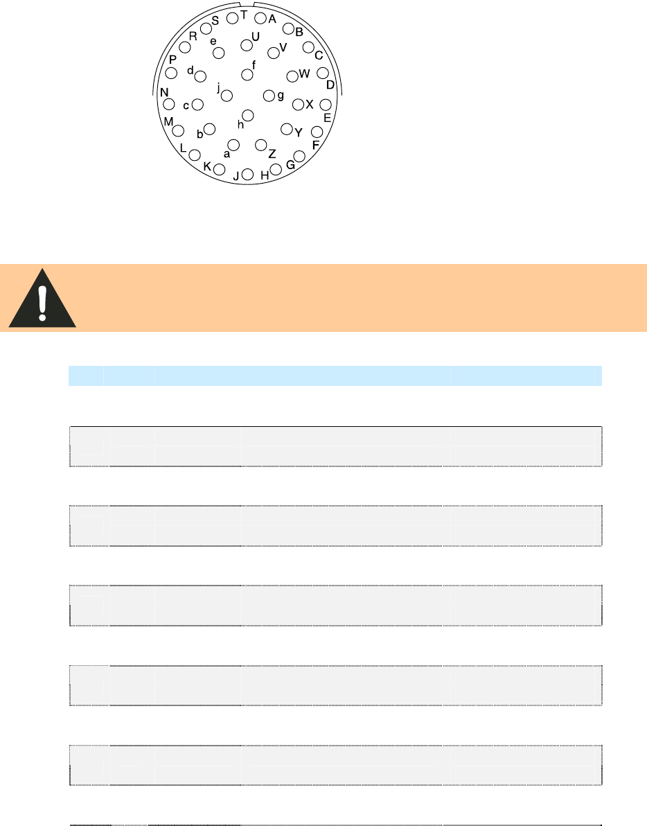
1 2 3 4 5 6 7
8
9
Specifications
IDentity 4100 User Guide
85
Bulkhead Connector/Interface Cable Pinout
Note: Drawing is for cable socket on reader.
WARNING:
Do not place ID4100 or ID5100 on wire harness for existing ID-MAX
installations. Power pins have been moved!
Verify power wiring prior to first powering up unit!
Pair Pin Color Pin Name Function
A Black Tx+ Ethernet
1 B Green Tx- Ethernet
C Black Rx+ Ethernet
2 D Orange Rx- Ethernet
E Blue VC2+ Ethernet
3 F Black VC2- Ethernet
G Black VC2+ Ethernet
4 H Brown VC2- Ethernet
J Black RS-232 TXD (to WIM RXD) Serial or WIM Port
5 K Red RS-232 RXD (to WIM TXD) Serial or WIM Port
L Black DTR (Short to Pin N DSR) Serial or WIM Port
6 M White RS-232 GND (to WIM SGND) Serial or WIM Port
N Black DSR (Short to Pin L DTR) Serial or WIM Port
7 P Yellow RS-232 CTS (to WIM RTS) Serial or WIM Port
R Red RS-232 RTS (to WIM CTS) Serial or WIM Port
8 S White No Connect Not Applicable
T Red +24 VDC Power
9 U Green 24 VDC GND Ground
V Red DIN Ref 1 To (+5 to +24)VRef Digital Input Common
10 W Blue DIN1 Digital Input 1
X Red DIN2 Digital Input 2
11 Y Yellow DIN Ref 2 To (+5 to +24)VRef Digital Input Common

1 2 3 4 5 6 7
8
9
Specifications
86
IDentity 4100 User Guide
Pair Pin Color Pin Name Function
Z Red DIN3 Digital Input 3
12 a Brown DIN4 Digital Input 4
b Red GND Ground (Reader)
13 c Orange DOUT1 Digital Output 1
d Green DOUT2 Digital Output 2
14 e White DOUT3 Digital Output 3
f Green DOUT4 Digital Output 4
15 g Blue GND Ground (Reader)
h No Connect Not Applicable Not Applicable
16 j No Connect Not Applicable Not Applicable

1 2 3 4 5 6 7 8
9
Safety and Regulatory Information
IDentity 4100 User Guide
87
Safety and Regulatory Information
Power Disconnect Device
The plug on the power supply cord is intended to be the power disconnect
device. As a result, the power source (socket or outlet) shall be located near
the equipment and shall be easily accessible.
FCC Notice (IDentity 4100)
This equipment has been tested and found to comply with the limits for a
Class A digital device, pursuant to Part 15 of the FCC Rules. These limits are
designed to provide reasonable protection against harmful interference
when the equipment is operated in a commercial environment. This
equipment generates, uses, and can radiate radio frequency energy and, if
not installed and used in accordance with the instruction manual, may
cause harmful interference to radio communications. Operation of this
equipment in a residential area is likely to cause harmful interference in
which case the user will be required to correct the interference at his own
expense.
FCC Notice (Wiegand Interface Module)
The Wiegand Interface Module has been tested and found to comply with
the limits for a Class B digital device, pursuant to Part 15 of the FCC Rules.
These limits are designed to provide reasonable protection against harmful
interference in a residential installation. This equipment generates, uses
and can radiate radio frequency energy and, if not installed and used in
accordance with the instructions, may cause harmful interference to radio
communications. However, there is no guarantee that interference will not
occur in a particular installation. If this equipment does cause harmful
interference to radio or television reception, which can be determined by
turning the equipment off and on, the user is encouraged to try to correct
the interference by one or more of the following measures:
h
Reorient or relocate the receiving antenna.
h
Increase the separation between the equipment and receiver.
h
Connect the equipment into an outlet on a circuit different from that to
which the receiver is connected.
h
Consult the dealer or an experienced radio/TV technician for help.
1 2 3 4 5 6 7 8
9
Safety and Regulatory Information
88
IDentity 4100 User Guide
RF Safety
WARNING:
FCC Radiation Exposure Statement (Models ID4100-001, ID4100-90). The
antennas used for this transmitter must be installed to provide a separation
distance of at least 1 meter from all persons and must not be co-located or
operating in conjunction with any other antenna or transmitter.
ETSI Radiation Exposure Statement (Models ID4100-001-ETSI, -002-ETSI. The
antennas used for this transmitter must be installed to provide a separation
distance of at least 25 cm from all persons and must not be co-located or
operating in conjunction with any other antenna or transmitter.
Caution:
The IDentity 4100 UHF Reader is equipped with two (2) RF ports and is
factory configured to operate on the internal RF port (1). To prevent reader
damage, the external RF Port (2) must be properly terminated with a 50 ohm
load or a functional UHF antenna before power up if the reader has been
configured to use this port. Never power up the reader unless the appropriate
loads or antennas are connected. Always power down the reader before
removing an antenna or load from an RF port.
The maximum antenna cable length is 10 meters.
Electrostatic Discharge
ATTENTION
IDentity 4100 antenna ports may be susceptible to damage from static
discharge or other high voltage. Use proper Electrostatic Discharge
(ESD) precautions to avoid static discharge when handling or making
connections to the IDentity 4100 reader antenna or communication
ports. Equipment failure can result if the antenna or communication
ports are subjected to ESD.
Regulatory Compliance
Caution:
The IDentity 4100 is designed to meet the regulatory requirements in those
jurisdictions in which it is offered. Changes or modifications not expressly
approved by Sirit Technologies for compliance could void the user's authority
to operate the equipment.
Power/Data Cable Size
Caution:
The Sirit supplied power/data cable is only to be used with the Sirit 24 VDC power
supply. Use of these cables with power supplies providing lesser voltages may
result in cable and/or reader damage.

Appendix A Using the Wiegand Interface
IDentity 4100 User Guide
89
A
Using the Wiegand Interface
A.1.
Overview
The Sirit Wiegand Interface Module
(WIM) is a serial (RS-232) to 4-channel
Wiegand module designed to interface
with the ID4100 UHF RFID reader.
Currently, 2 Wiegand channels are
used, corresponding to the 2 antennas
available on the ID4100. Channel 1 is
associated with the Internal antenna.
Channel 2 is associated with the
External antenna.
Channels 3 and 4 can be configured to
act as open-collector, digital pulse
outputs under software control. This requires an additional custom script
file to define the output function. Contact your local Sirit Representative for
further information.
A.2.
Wiegand Protocol
The Wiegand communication protocol is a 3-wire communications scheme
comprising:
h Data One line
h Data Zero line
h Ground line
These three lines constitute a Wiegand Channel.
Data is transmitted in a serial manner over these lines by pulsing the Data
One line low for a logic 1, and pulsing the Data Zero line low for a logic 0.
Two parameters define the behavior of bit-wise transmission:
h Pulse Width Time (Tpw) is the duration of the pulse.
h Pulse Interval Time (Tpi) is the interval between the end of a pulse and
the start of the next pulse.
Based on this, the total bit time is Tpw + Tpi.

Appendix A Using the Wiegand Interface
90
IDentity 4100 User Guide
A Wiegand frame consists of a string of bits transmitted in the Wiegand
format. Typically, this is 26 bits (including two parity bits). Following the
transmission of a Wiegand frame, a hold-off time (Thold) is asserted where
the Wiegand interface will not transmit. This mechanism is used to separate
adjacent Wiegand frames.
The unit, by default, outputs a 26-bit Wiegand frame (24 data bits , 2 parity
bits). Data lengths of up-to 128 bits can be accommodated. The current
default values for the Wiegand are as follows:
Parameter Value
TPW Pulse Width Time 50 µs
TPI Pulse Interval Time 2000 µs
Inter Frame Message Delay Time 250 ms
Data bits 24
Parity Standard
Bit format MSB first
For more information, refer to the AC-01 Wiegand Specification: “Access
Control Standard Protocol For The 26-Bit Wiegand Reader Interface”.
A.3.
Wiegand Applications
Many access control panels incorporate a Wiegand Interface, and in many
applications a host reader will communicate with an access control panel
via the Wiegand Interface. Many Wiegand-enabled panels are configured to
receive Facility Code information and Serial Number information in Wiegand
format.
In an RFID-based access control system, the Facility Code and Serial
Number may be embedded into a data string known as a Translated ID. In
some applications, an actual tag ID may be mapped to a Translated ID via
some form of look-up table.
This ID4100 Wiegand application primarily uses secure tags for
authentication. The reader will read such tags and derive a Translated ID
from the tag. This Translated ID is then sent to the Wiegand Interface
Module (WIM) for transmission over a Wiegand Interface to a Wiegand
panel. However, a translation table facility is incorporated for managing
standard legacy tags.
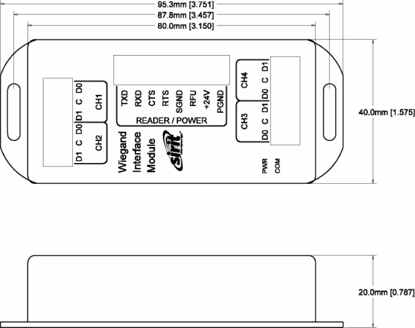
Appendix A Using the Wiegand Interface
IDentity 4100 User Guide
91
A.4.
Mechanical Installation
The WIM is housed in a plastic enclosure and should be located in your
control panel. Mount the module in a ventilated area on a flat panel and
ensure that the module is protected from water and moisture ingress, and
is not mounted directly above a heat source.
Secure the module in place with two #8 (M4) flat-head type screws. Figure 7
shows the location of the mounting flanges.
Figure 7 Wiegand Interface Mounting Flanges
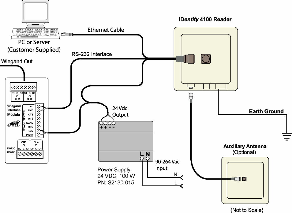
Appendix A Using the Wiegand Interface
92
IDentity 4100 User Guide
A.5.
Electrical Installation
Power for the WIM is supplied by the 24 VDC ID4100 reader power supply.
The ID4100 serial port is used to communicate with the WIM and is
therefore not available for standard serial communications. Connections to
the WIM are made via pluggable screw terminal blocks.
Figure 8 IDentity 4100 Electrical Connections (Wiegand Interface Module)
Refer to Figure 9 for actual Wiegand Module power and RS-232 wiring.
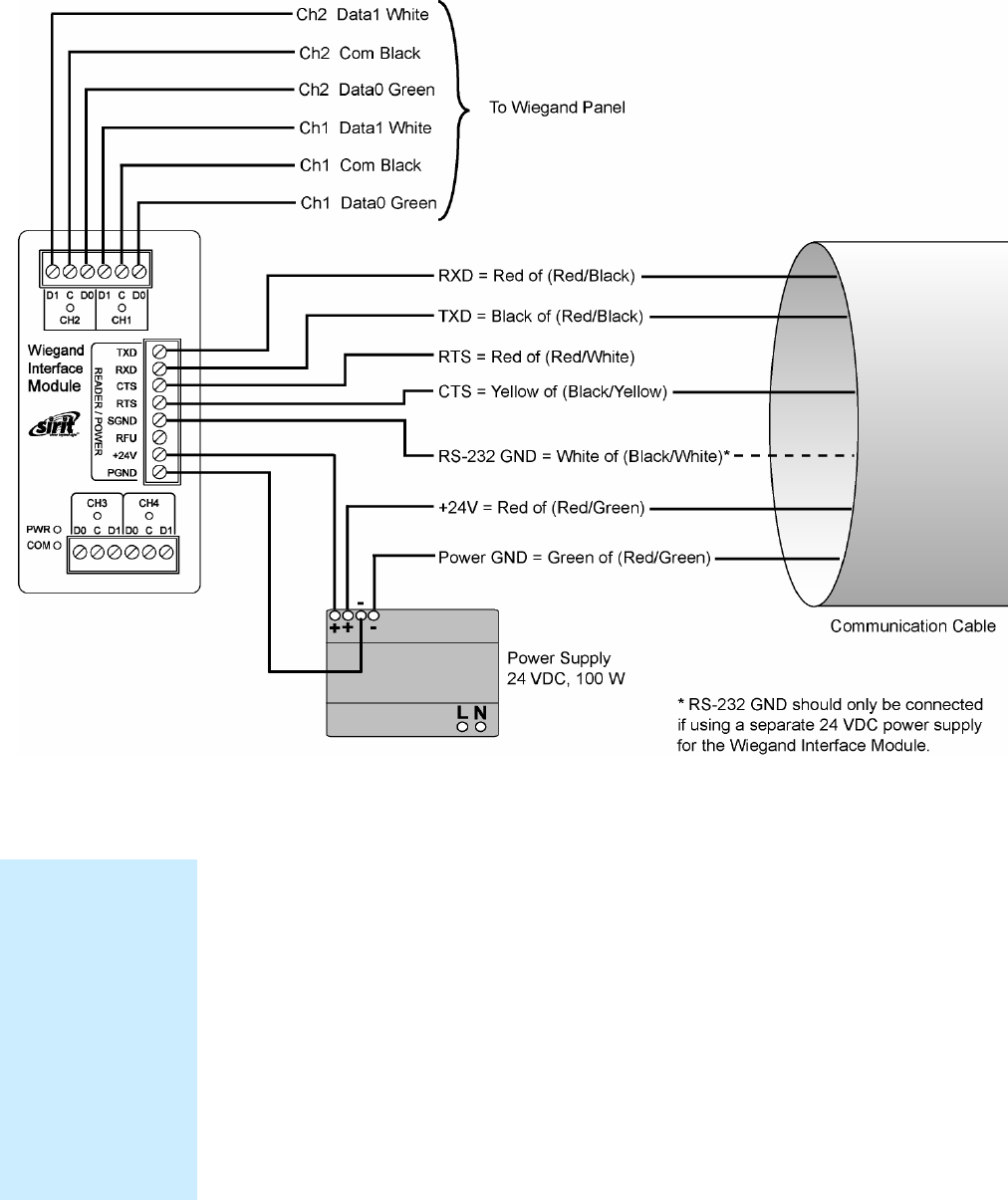
Appendix A Using the Wiegand Interface
IDentity 4100 User Guide
93
Figure 9
Wiegand Interface Module Electrical Connections
Connect the Serial Port
To connect the serial port, perform the following:
1 Terminate the reader umbilical cable using a suitable cable gland or
equivalent method.
2 Identify the serial interface wires and terminate these five wires on the
READER/POWER
connector.
3 Use care when performing the termination to avoid Pin 3 (
RFU
) on this
connector.
Disconnecting WIM
from Serial Port
In the event you
disconnect the WIM
module from the
serial port, you need
to restart the console
service for the reader
command line
interface (cli).
See “Disconnecting
the Wiegand
Interface Module”
later in the is section.
Appendix A Using the Wiegand Interface
94
IDentity 4100 User Guide
Connect the Wiegand Outputs
Optically-isolated open-collector outputs are provided to meet the
requirements of the AC01 Wiegand specification. These are protected by 5V
transient voltage-suppression diodes.
To connect the Wiegand outputs, perform the following:
1 When using the single Internal antenna of the ID4100, connect CH1 (3
wires) of the WIM to the Wiegand panel.
2 If using the External antenna, connect CH2 (3 wires) of the WIM to the
Wiegand panel.
3 Refer to Figure 9 for the standard Wiegand color code as defined in the
AC-01 Wiegand specification.
Connect the 24V Power
To connect 24V power, perform the following:
1 Using the black and red power harness supplied, connect one end of
the black wire to Terminal 1 (
PGND
).
2 Connect one end of the red wire to Terminal 2 (
+24V
) of the
READER/POWER
connector.
3 Connect the remaining end of the red wire to the + output terminal.
4 Connect the remaining end of the black wire to the – output terminal of
the PSU
5 Verify the connections.
Initial Testing
Initial testing is optional, but recommended. The purpose is to verify that
the 24V PSU and Wiegand module power supply are operating correctly.
Perform the following:
1 Ensure that the reader is disconnected from the umbilical cable by
unlocking and removing the connector at the reader end.
2 Apply AC power to the PSU Module.
3 Using a Digital Multimeter (DMM) confirm that the output of the PSU
lies in the range 21.6 to 26.4 VDC
4 Check that the
PWR LED
on the module is illuminated.
5 Using the DMM, measure the DC voltage between
PGND
and
RFU
on
the
READER/POWER
connector. For correct operation, this should be
between 4.75 and 5.25 VDC.
6 Disconnect the PSU and reconnect the umbilical cord to the reader.
Appendix A Using the Wiegand Interface
IDentity 4100 User Guide
95
A.6.
Disconnecting the Wiegand Interface Module
In the event you wish to disconnect the WIM, perform the following:
1 Remove AC power from the PSU.
2 Disconnect the serial cable from the reader.
3 Restart the console service for the reader command line interface by
sending the following command to the reader:
com.serial.console(program=cli)
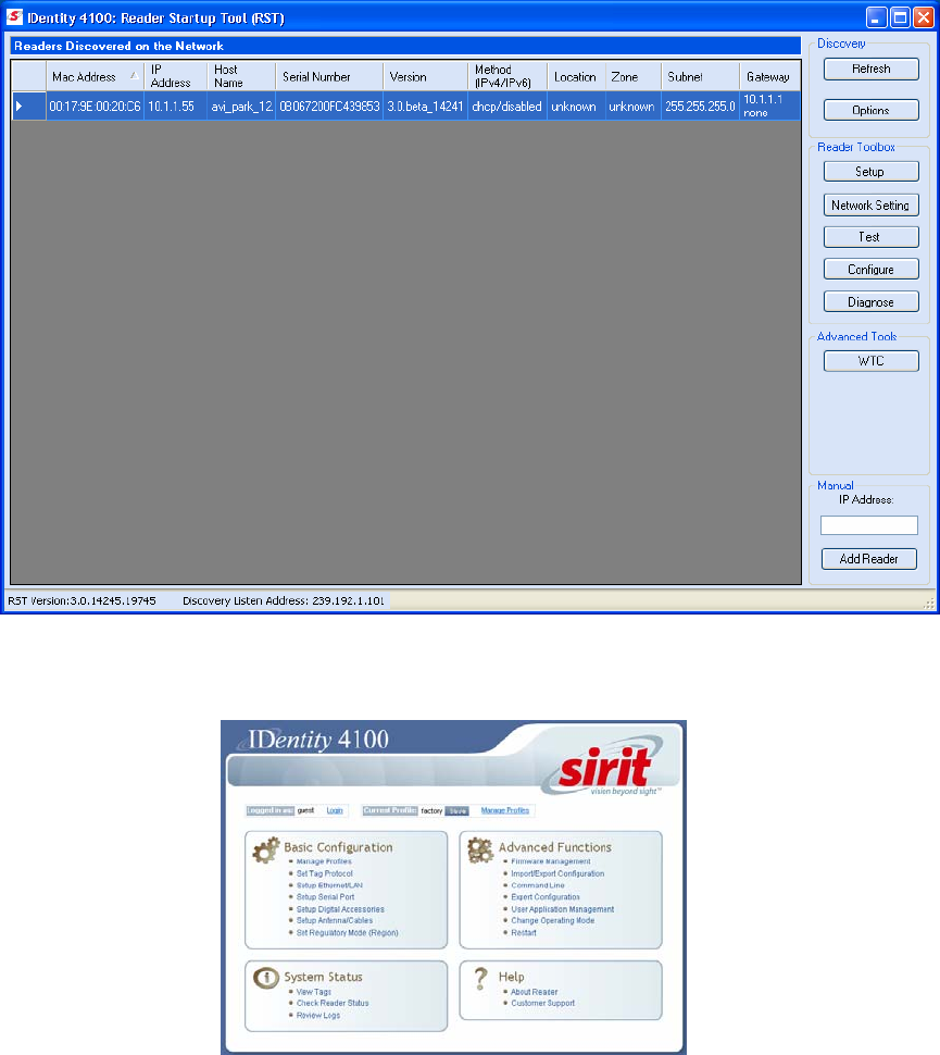
Appendix A Using the Wiegand Interface
96
IDentity 4100 User Guide
A.7.
Using RCT to Configure the Wiegand Interface Module
You can use the embedded Reader Configuration Tool to configure the WIM
parameters. Perform the following:
Open RST
1 From your Windows desktop, select:
Start→Programs→Sirit→IDentity4100→Reader Startup Tool (RST)
2 Select a specific reader and press
Configure
.
3 The Reader Configuration Tool (RCT) is displayed.
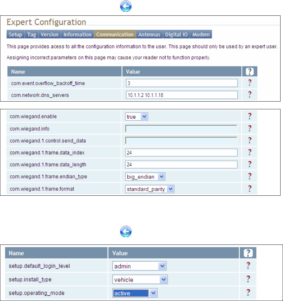
Appendix A Using the Wiegand Interface
IDentity 4100 User Guide
97
4 Press
Login
and log into the reader as admin. The initial password is
readeradmin.
5 Select
Advanced Functions
→
Expert Configuration
.
6 Select the
Communication
tab.
7 Set
com.wiegand.enable
to
true
and press
Submit
.
8 Press the Back key to return to
Expert Configuration
screen.
9 Select the
Setup
tab.
10 Set
setup.operating_mode
to
active
and press
Submit
.
11 Press the Back key to return to
Expert Configuration
screen.
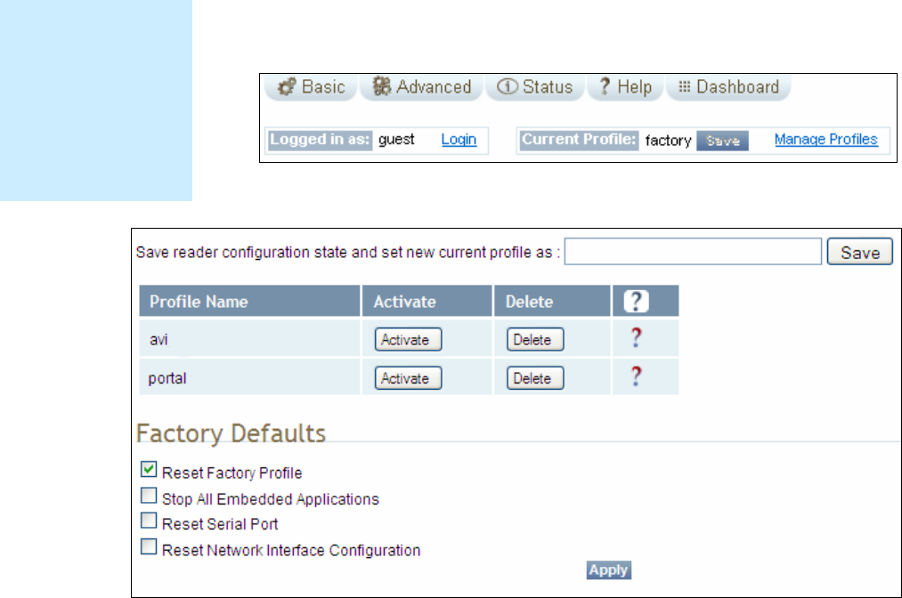
Appendix A Using the Wiegand Interface
98
IDentity 4100 User Guide
12 Once setup is complete, save your settings in a
Profile
.
13 In the configuration header, press
Manage Profiles
.
14 The profile management page is displayed
15 Enter a profile name in the box and press
Save
.
16 Your reader configuration will be saved under this profile name and can
be quickly reloaded if the reader reboots or you lose your reader
configuration.
17 To load a profile, press the
Activate
button next to the
Profile Name
.
Save Reader Setup
Save reader setup
information as a
profile. If you need to
reboot or power down
a reader, the reader
setup can be quickly
reloaded by loading
the profile.
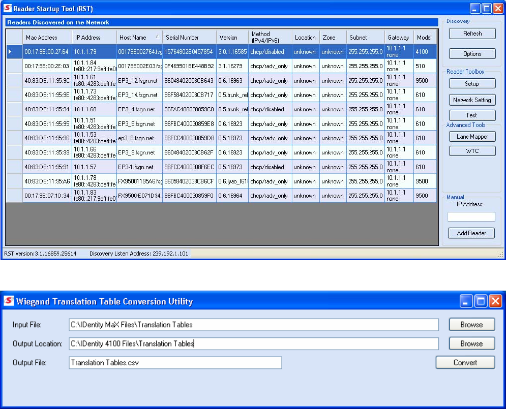
Appendix A Using the Wiegand Interface
IDentity 4100 User Guide
99
A.8.
Converting Translation Tables for use with IDentity 4100
If you have translation tables, such as those developed for IDentity MaX
readers, these tables can be converted for use with the IDentity 4100 and
Wiegand Interface Module.
For a Single Translation Table
1 From your Windows desktop, select:
Start→Programs→Sirit→IDentity4100→Reader Startup Tool (RST)
2 Press the
WTC
button under
Advanced Tools
.
3 Enter the location and name of your input file, output file location, and
output file name.
4 Press
Convert
.
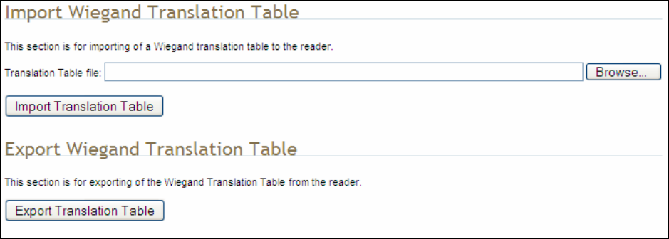
Appendix A Using the Wiegand Interface
100
IDentity 4100 User Guide
For Multiple Translation Tables
1 If you have multiple translation tables to convert, perform the previous
procedure for each table.
2 Create a new document using a text editor such as Notepad. This will
be the main file used to build the combined translation table.
3 Start another session of the text editor (such as Notepad) to open one
of the converted translation tables.
4 Copy the contents and paste them into the main file. (The converted
translation tables have a
.csv
extension. Do not open these by double-
clicking, as this will invoke Excel).
5 Repeat Step 3 for all converted tables.
6 Use care to not replicate the same information multiple times. Edit the
main file if necessary to eliminate duplications.
7 Save the main file, giving it a
.csv
extension.
A.9.
Importing/Exporting a Translation Table
To load or import a translation table, perform the following:
1 Under the Advanced Functions, select Import/Export Configuration.
2 Under Import Wiegand Translation Table, press Browse and navigate
to the location of your translaitons tables.
3 Select the translation table file name and press Import Translation
Table.
4 To export the translation table, press Export Translation Table.
5 Save the file as needed.

Appendix A Using the Wiegand Interface
IDentity 4100 User Guide
101
A.10.
Programming the Wiegand Interface
The WIM may be configured in hardware to contain two or four Wiegand
channels. Each channel can be individually configured and controlled.
In the following variable and function descriptions <n> will refer to a generic
Wiegand channel. Valid values include 1,2 (Wiegand channels 1, 2) for all
systems and 3,4 (Wiegand channels 3, 4) for four channel modules. (See
Module Type 0x14 in the com.wiegand.info variable description). A
channel value falling out of range should generate an error.
For this system, Wiegand channel 1 is associated with the Internal antenna
and Wiegand channel 2 is associated with the External antenna.
com.wiegand.dealer_code_list
This variable is used to configure a string of dealer codes.
A Dealer Code List can be configured with one or more Dealer Codes, each
separated by a "space". Authenticated secure tags containing a Dealer Code
which matches a value in the Dealer Code List will be forwarded to the
Wiegand interface. Authenticated secure tags containing a Dealer Code that
does not match a value in the Dealer Code List will be blocked. Dealer Code
filtering does not apply to legacy tags. Dealer Code filtering can be disabled
by specifying a blank Dealer Code List.
Type var
Permissions guest=r,admin=rw
Data Type string
Default ""
com.wiegand.dealer_code_list
This variable provides a space-separated list of dealer codes used by
Wiegand application to filter out tags. Empty list means no dealer code is
used.
Type var
Permissions guest=r,admin=rw
Data Type string
Default ""

Appendix A Using the Wiegand Interface
102
IDentity 4100 User Guide
com.wiegand.enable
This variable enables/disables the WIM.
Type var
Permissions guest=r,admin=rw
Data Type bool
Default false
com.wiegand.events_only
If this variable is set to true, WIMApp will run and use the translation table,
but will not actually communicate with a Wiegand Interface Module over the
serial port. event.wim.report events are generated, and this is the only
output from WIMAPP.
This mode is intended to be used in order to allow WIMAPP to perform
access control functionality using the translation table as a whitelist. When
false, WIMAPP attempts to communicate with the Wiegand Interface
Module on the serial port and will not function properly if this
communication is impossible.
Type var
Permissions guest=r,admin=rw
Data Type bool
Default true
com.wiegand.export_table
Export translation table of the Wiegand module to /tmp/wim/table.
Type function
Permissions guest=-,admin=x
com.wiegand.import_table
Import translation table of the Wiegand module.
Type function
Permissions guest=-,admin=x
Parameters file (string)

Appendix A Using the Wiegand Interface
IDentity 4100 User Guide
103
com.wiegand.info
This variable returns a string containing information about the WIM, such as
number of channels (channels), firmware version number
(firmware_version) and serial number (serial_no).
>>> com.wiegand.info()
ok channels=4, firmware_version=0.25,
serial_no=0x1122334455667788
Type var
Permissions guest=r,admin=rw
Data Type string
Default ""
com.wiegand.reset
This function resets the WIM.
Type function
Permissions guest=-,admin=x
com.wiegand.retransmission_interval
This variable provides the facility for a Wiegand stream to be retransmitted
at defined periodic intervals for the time a tag resides in the RF field. This
variable defines the interval in seconds. A value of 0 disables the
retransmission mechanism.
Type var
Permissions guest=r,admin=rw
Data Type int
Default 0
Min 0
Max 300

Appendix A Using the Wiegand Interface
104
IDentity 4100 User Guide
com.wiegand.<n>.control.send_data
This variable sends data to the Wiegand interface. The data is specified in
hexadecimal form (for example, 0xXXXXXXXXXXXXXXXX) and represents a
value of up-to 8 bytes. The data will typically represent a translated ID. n = 1
to 4.
Type var
Permissions guest=r,admin=rw
Data Type string
Default ""
com.wiegand.<n>.control.send_test_pattern
Send a fixed, predetermined test pattern to the Wiegand channel.
n = 1 to 4.
Type function
Permissions guest=-,admin=x
com.wiegand.<n>.frame.data_index
This variable sets or interrogates the data index. This is the index, in bits,
where serialization of the translated ID begins (for discarding
unused/redundant translated ID bits, for example Dealer Code). n = 1 to 4.
Type var
Permissions guest=rw,admin=rw
Data Type int
Default 24
Min 0
Max 255

Appendix A Using the Wiegand Interface
IDentity 4100 User Guide
105
com.wiegand.<n>.frame.data_length
This variable sets or interrogates the data length of the Wiegand frame. This
defines the total number of bits (excluding parity bits) of a translated ID that
will be transmitted over the Wiegand interface. n = 1 to 4.
Type var
Permissions guest=r,admin=rw
Data Type int
Default 24
Min 1
Max 112
com.wiegand.<n>.frame.endian_type
This variable sets or interrogates the endian type of the Wiegand output
frame. This defines whether the most-significant, or least- significant bit of
the selected portion of the translated ID will be transmitted first. n = 1 to 4.
Type var
Permissions guest=r,admin=rw
Data Type enum
Default BIG_ENDIAN
Enum BIG_ENDIAN LITTLE_ENDIAN
com.wiegand.<n>.frame.format
This variable sets or interrogates the frame format of the Wiegand output. n
= 1 to 4.
Type var
Permissions guest=r,admin=rw
Data Type enum
Default STANDARD_PARITY
Enum STANDARD_PARITY REVERSE_PARITY CHECKSUM RAW_DATA

Appendix A Using the Wiegand Interface
106
IDentity 4100 User Guide
com.wiegand.<n>.physical.thold
This variable is used to set or to interrogate the inter-frame hold-off time
(Thold), where the inter-frame hold-off time is specified in milliseconds.
Values of 50 to 20,000 ms are valid. The default value is 250 ms. The
variable will return a value in the range 50 to 20,000 ms. n = 1 to 4.
Note that the WIM has a granularity of 50 ms and hold-off times will be
truncated to the nearest 50 ms.
Type var
Permissions guest=r,admin=rw
Data Type int
Default 5
Min 50
Max 20000
com.wiegand.<n>.physical.tpi
This variable is used to set or interrogate the pulse interval time, where the
pulse interval time is specified in microseconds. Values of 200 µs to
20,000 µs are valid. The default value is 2000 µs. The variable will return a
value in the range 200 to 20,000 µs. n = 1 to 4.
Note that the WIM has a granularity of 200 µs. Therefore,
pulse_interval_times will be truncated to the nearest 200 µs.
Type var
Permissions guest=r,admin=rw
Data Type int
Default 2000
Min 200
Max 20000

Appendix A Using the Wiegand Interface
IDentity 4100 User Guide
107
com.wiegand.<n>.physical.tpw
This variable is used to set or to interrogate the pulse width time (Tpw),
where the pulse width time is specified in microseconds. Values of 40 to
250 µs are valid. The default value is 50 µs. The variable will return a value
in the range 40 to 250 µs. n = 1 to 4.
Note that the WIM has a granularity of 5 µs and pulse_width_times will be
truncated to the nearest 5 µs.
Also note that these are nominal time values for 470Ω pull-up loads on the
Wiegand outputs. The pulse width time lengthens for higher values of pull-
ups, and shortens for lower values. This phenomenon is caused by Miller
capacitance on the loads. The 5 µs granularity on the pulse_width_time can
be used to tailor the pulse width to the required value.
Type var
Permissions guest=r,admin=rw
Data Type int
Default 50
Min 40
Max 255
error.wiegand.failure
This response indicates WIM function failed.
event.wim.report
This event is generated each time data is sent to the WIM interface. The
event returns the translated ID, timestamp, and antenna value
Type event
Permissions guest=rw,admin=rw
Return Values
id (int)
time (string)
text (string)

Appendix A Using the Wiegand Interface
108
IDentity 4100 User Guide
definitions.enum.wiegand.frame.endian_type
This variable sets wiegand module ouput frame endian type.
Type var
Permissions guest=,admin=
Data Type enum
Default BIG_ENDIAN
Enum BIG_ENDIAN LITTLE_ENDIAN
definitions.enum.wiegand.frame.format
This variable sets wiegand module ouput frame format.
Type var
Permissions guest=,admin=
Data Type enum
Default STANDARD_PARITY
Enum STANDARD_PARITY REVERSE_PARITY CHECKSUM
RAW_DATA
Appendix A Using the Wiegand Interface
IDentity 4100 User Guide
109
A.11.
Programming the Translation Table
The ID4100 has a translation table facility that allows a translation table to
be imported into the reader. This facility serves three primary functions:
h Support the use of legacy tags.
h Manage exceptions, such as the black-listing of tags.
h Serve as the list of allowed (and/or black-listed) tags for a standalone
access control system (See Standalone Reader Operation Application
Note).
Translation Table Format
The translation table uses a comma-separated variable (csv) format and will
typically have a .csv extension. The first line of the file must contain the
version number of the file format. Currently the file format version is 1.0.
Each subsequent line of the file represents a sequence of tags and has the
following format:
[StartID],[TagType],[StartXlateID],[Entries],[Handler
]<CR><LF>
where:
[StartID] is the first tag ID of a sequence of tag IDs. In most cases,
this is a hexadecimal number, preceded by 0x. If the tag protocol is
configured to display tag IDs in 6 bit ASCII format, this is the ASCII string
representing the starting tag ID. In the ASCII tag case, this is typically a
4 letter identifier followed by a 8 digit decimal number.
[TagType] is the tag protocol type. This must be one of the protocols
supported by the reader, for example, ISOC or ISOB.
[StartXlateID] is the first translated ID (in hex) of a sequence of
translated IDs. The number is preceded by 0x.
[Entries] is presented as a decimal number representing the
number of tags in the sequence.
[Handler] determines how the ID4100 should process a tag and is a
decimal number (between 0 and 255) that applies to all tags in the
sequence. Where:
Bit 7: Password Authentication Indicator
1 = Password Authenticated
0 = Not Password Authenticated
Bit 6: Blacklist Indicator
1 = Blacklisted
0 = not Blacklisted
Appendix A Using the Wiegand Interface
110
IDentity 4100 User Guide
Bit 5: TID Authentication Indicator
1 = TID Authenticated
0 = Not TID Authenticated
Bit 4: RFU (0)
Bit 3: RFU (0)
Bit 2: RFU (0)
Bit 1: RFU (0)
Bit 0: Handler value
1 = Pass Translated ID to WIM
0 = Do not pass translated ID to WIM
Typical Handler values
h 1 – Legacy tag whose data is to be passed through the system to the
Wiegand interface (00000001b)
h 64 – Black-listed Legacy tag (01000000b).
h 33 – TID-Authenticated Tag whose data is to be passed through the
system to the Wiegand interface (00100001b).
h 96 – Black-listed TID-Authenticated tag (01100000b).
h 129 – Password-Authenticated Tag whose data is to be passed through
the system to the Wiegand interface (10000001b).
h 192 – Black-listed Password-Authenticated tag (11000000b).
Example Table Entry
The following is a typical translation table entry.
0x000000000000000000010000,ISOC,
0x000A0100,1000,1<CR><LF>
This entry indicates:
h 1000 ISOC protocol tags in the sequence
h Each with a handler value of 1 (legacy tag passed through system)
h Actual tag IDs range from 0x000000000000000000010000 to
0x0000000000000000000103E7
h Corresponding translated IDs would range from 0x000A0100 to
0x000A04E7
Appendix A Using the Wiegand Interface
IDentity 4100 User Guide
111
A.12.
Interaction between Translation Table and Wiegand-
Encoded Tags
Some tags are encoded with Wiegand data directly on them. The IDentity
4100 supports these direct Wiegand encoded tags of the following format:
h Secure ISOC
h ISOB
h ISO10374 (if supported by your model of IDentity 4100)
h Flex (if supported by your model of IDentity 4100)
Because of the security features present on direct Wiegand encoded Secure
ISOC tags, they can be positively identified, and the Wiegand data encoded
on the tag is transmitted via the WIM. For each of the other protocols, some
C2 variables are used to enable the direct Wiegand feature on a protocol-
by-protocol basis:
h modem.protocol.isob.control.wiegand.enabled
h modem.protocol.iso10374.control.wiegand.enabled
h modem.protocol.flex.control.wiegand.enabled
When these variables are set to "true", WIMapp will perform the following
actions when a tag is read:
1. The standard tag ID will be looked up in the translation table (described
above). If there is an entry matching the tag ID in the translation table,
the action specified by the translation table entry will be performed.
2. If the tag ID is not present in the translation table, and if the direct
Wiegand feature is enabled via the variables above, then the Wiegand
data encoded on the tag will be transmitted via the WIM.
Although the default values are correct for most installations, and should
not be changed without consulting Sirit technical support, it is possible to
modify the areas in tag memory from which the Wiegand data is extracted
by changing the following variables:
h modem.protocol.isob.control.wiegand.length
h modem.protocol.isob.control.wiegand.offset
h modem.protocol.iso10374.control.wiegand.length
h modem.protocol.iso10374.control.wiegand.offset
h modem.protocol.flex.control.wiegand.length
h modem.protocol.flex.control.wiegand.offset
Appendix A Using the Wiegand Interface
112
IDentity 4100 User Guide
A.13.
Transaction Log
A transaction log is used to record information on tag arrivals. Each entry in
the log contains the following information:-
[time] – provides the date and time of the tag arrival.
[tag_id] – ID of the tag.
[antenna] – states the antenna where the tag was read.
[handle] – 8-bit values that provide information about a tag upon its
arrival. The bit values are defined as:
Bit 7 Password Authentication
1 = Password Authenticated
0 = Not Password Authenticated
Bit 6 Blacklist Indicator
1 = Blacklisted
0 = Not Blacklisted
Bit 5 TID-Authentication
1 = TID Authenticated
0 = Not TID Authenticated
Bit 4 User Data Read Failure
1 = Failed To Read User Data
0 = User Data Read (for authenticated tag)
(or) Not Applicable (for legacy tag)
Bit 3 Dealer Code Mismatch
1 = Dealer Code Mismatch
0 = Dealer Code Match (for authenticated tag)
(or) Not Applicable (for legacy tag)
Bit 2 RFU
Bit 1 RFU
Bit 0 Wiegand Access
1 = Translated ID passed to Wiegand interface.
0 = No data passed to Wiegand interface.
[type] – tag protocol type
[translated_id] – hexadecimal value of the translated tag ID (result of
the translation table lookup).

Appendix A Using the Wiegand Interface
IDentity 4100 User Guide
113
A.14.
Module Specifications
Operating Temperature Range -40C to +60C
Storage Temperature Range -40C to +85C
DC Power Input 12V-28V DC reverse polarity protected
Total Power Consumption <1.25W (equivalent to <60mA @ 24VDC)
RS-232 Serial Port 115,200 Baud, 8 Bits, No Parity, 1 Stop Bit
Wiegand Port Data Zero and Data One outputs
Configuration type 5Y (See App A of AC-01 Wiegand Specification)
Outputs Optically isolated open-collector outputs
capable of sinking 25mA
These outputs will need to be pulled up to 5V at
the inputs of the terminating Wiegand panel.
Optimum pull-up resistor values lie in the range
470Ω to 1kΩ.
Tpw (Output Pulse Width) 40 µs -255µs in 5µs increments
(with 470Ω pull-up resistor)
Tpi (Output Pulse Interval) 200µs to 20ms in 200µs steps
Hold-off time 50ms-20s in 50ms steps
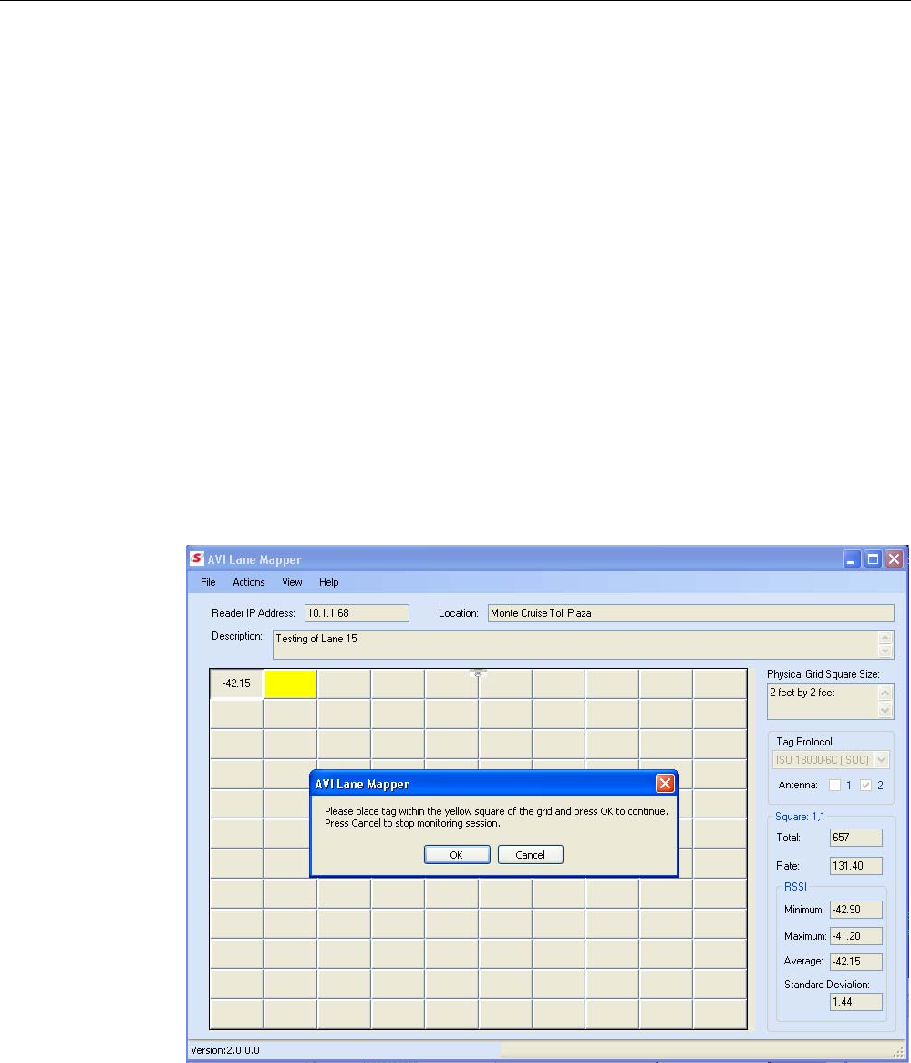
Appendix B AVI Lane Mapper
114
IDentity 4100 User Guide
B AVI Lane Mapper
B.1.
Overview of the AVI Lane Mapper
The AVI Lane Mapper application determines the tag read rate and the
signal strength of tags in a toll lane antenna field. This helps identify weak
and strong areas within the antenna field.
The lane in the antenna field is divided into a grid. A tag is placed within
each grid square and measurements are taken including the number of
times the tag is read and the RSSI of each read for a given length of time
(polling interval). One set of polling intervals is called a monitoring session.
There are three types of monitoring sessions:
h Prompt
h Automatic
h User Select
Prompt and Automatic index through the grid sequentially while User Select
allows the user to select the squares in any order. The type of Monitoring
Session to be run is defined on the Options dialog. The default Monitoring
Session type is Prompt.
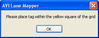
Appendix B AVI Lane Mapper
IDentity 4100 User Guide
115
Prompt Monitoring Session
During a Prompt monitoring session, the user is prompted with a Message
Box at the start of the session and in between each polling interval. This
method allows for an unlimited time to setup the next grid square. The user
will need to press OK on the Message box before the next polling interval
begins.
When a Prompt Monitoring Session starts the first available grid in the
square is highlighted yellow. The utility gets the current reader configuration
before the first polling interval starts. A Message box is displayed prompting
the user to place a tag in the highlighted grid square.
After placing the tag within the specified grid square, a polling interval will
start. A progress bar is displayed during a polling interval.
At the end of the polling interval, the following results are calculated for the
given grid square.
h Total number of tag reads
h The tag read rate per second
h The minimum RSSI sent by the reader
h The maximum RSSI sent by the reader
h The average RSSI seen during the polling interval.
h Standard Deviation of the RSSI sent by the reader.
These results are displayed to the left of the main screen for that grid
square. One of the following results maybe displayed in the grid square, if
there is room, the Tag read rate, Total number of tags read, or the average
RSSI. Which one maybe selected from the View menu.
The application verifies that only one tag was seen during the polling period.
If more than one tag is found, the square is highlighted in orange. Hovering
over a square with a warning will display a popup describing the warning.
A check is also made for a large variance in the standard deviation. This
check uses the values specified on the Options Dialog to determine a large
variance condition. If the condition is true, the grid square is highlight in red.
After displaying the read data, a message box is again displayed prompting
you to move the tag to the next grid square. An optional sound can be
played when this message box is displayed.
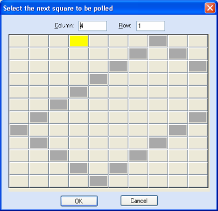
Appendix B AVI Lane Mapper
116
IDentity 4100 User Guide
Automatic Monitoring Session
The Automatic Monitoring Session the application waits a specified length
of time to setup the next grid square before beginning the polling interval.
This length of time is defined on the
Options
dialog. A sound is played at
the end of each polling interval.
When an Automatic Monitoring Session starts, the first available grid in the
square is highlighted yellow. The application obtains the current reader
configuration before the first polling interval starts. A progress bar is
displayed while the application is waiting to start the first polling interval.
When the waiting period has expired, the polling interval starts. A progress
bar is displayed whenever a polling interval is currently running.
The same results are displayed as the Prompt Monitoring Session and a
sound is played at the end of the polling interval before the next waiting
period begins.
User Select Monitoring Session
During this monitoring session, the user is prompted with a dialog at the
start of the session and in between each polling interval. This method
allows the you to select the next grid square to be polled and for an
unlimited time to setup the next grid square. This method can be used for
taking sampling data from just specific squares in the grid. You must press
OK
on the dialog before the next polling interval begins.
When a User Select Monitoring Session starts, the reader’s configuration is
retrieved from the reader. A dialog is displayed prompting you to select the
next grid to be polled.
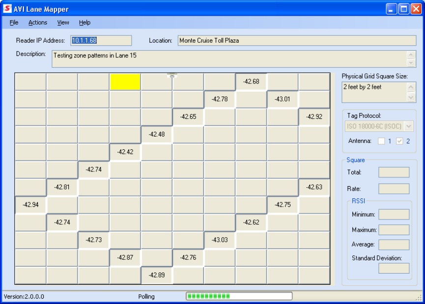
Appendix B AVI Lane Mapper
IDentity 4100 User Guide
117
Enter the column and row of the square or click the square to automatically
fill in the column and row. The currently selected square is highlighted in
yellow. Squares that contain polling interval data will be highlighted in dark
gray. Only squares that do not contain polling interval data may be selected
from this dialog. Double clicking on a square will select that square, close
the dialog, and then start the next polling interval.
Select
OK
on this dialog will start the polling interval. A progress bar is
displayed while the application is waiting to start the first polling interval.
The same results are displayed as the Prompt Monitoring and
the Select
next square to be polled
screen is displayed again. An optional sound bite
maybe played when this dialog is displayed. You can press
OK
to continue
the monitoring session or
Cancel
to stop the current session.
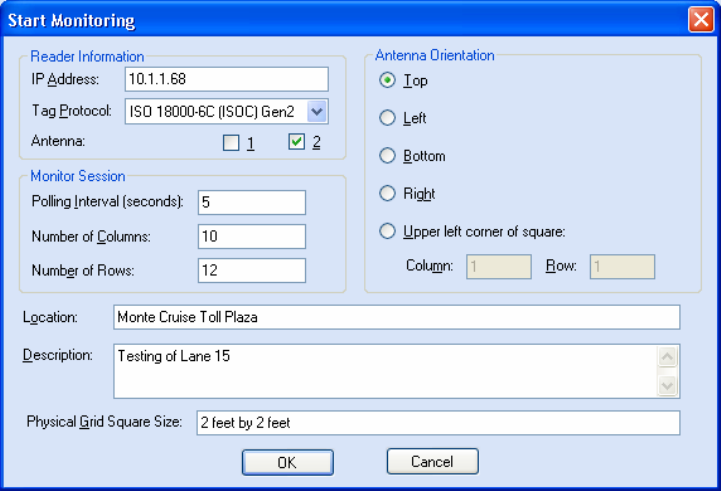
Appendix B AVI Lane Mapper
118
IDentity 4100 User Guide
B.2.
AVI Lane Mapper Operation
Start a Monitoring Session
1 To start a monitoring session, select:
Actions
→
Start Monitoring Session
2 The following dialog is displayed.
3 Enter the reader IP address, monitor parameters, and descriptive
information. If there are results from a previous monitoring session,
you may be prompted to save those results before starting a new
monitoring session.
• IP Address – IP Address of the reader. This field is required and if an
invalid or no address is specified, the application will display an
error. This value is displayed on the main screen when the
monitoring session is started.
• Tag Protocol – Protocol of tag used in the test. This will set the
reader only to use this tag protocol.
• Antenna – Antenna(s) to be used in the test. The checkboxes refer to
the antenna port on the reader. For IDentity 5100, 1 refers to the
internal antenna and 2 refers to the external antenna.
• Polling Interval – Length of a polling interval in seconds. This value
needs to be greater than 1. This field will automatically be filled in
with the value specified on the Options dialog.
Appendix B AVI Lane Mapper
IDentity 4100 User Guide
119
• Number of Columns – The number of columns displayed in the grid.
This value should be the same as the number of columns in the
physical grid. The valid range for this value is between 1 and 100.
This field will automatically be filled in with the last value specified.
• Number of Rows – The number of rows displayed in the grid. This
value should be the same as the number of rows in the physical grid.
The valid range for this value is between 1 and 65. This field will
automatically be filled in with the last value specified.
• Antenna Orientation – Specifies the location of the antenna relative
to the grid. A graphic of an antenna will be displayed on the grid for
the specified orientation.
• Top - Antenna is centered horizontally in front of the first row.
• Bottom - Antenna is centered horizontally behind the last row.
• Left - Antenna is centered vertically in front of the first
column.
• Right - Antenna is centered vertically behind the last column.
• Square - Antenna is placed within a given square of the grid.
This will allow areas all around the antenna to be tested. . This
field will automatically be filled in with the value specified on
the Options dialog.
• Location – Any information about the location where the monitoring
session is being executed. This field is optional and used for
informational purposes only. It will be stored with the monitor
session results. This value will be displayed on the main screen when
the monitoring session is started.
• Description – Descriptive information about the monitoring session,
such as reader or antenna settings. This field is optional and used for
informational purposes only. It will be stored with the monitor
session results. This value will be displayed on the main screen when
the monitoring session is started.
• Physical Grid Square Size – Dimensions of a square in the physical
grid being monitor, such as 2’x2’. This field is optional and used for
informational purposes only. It will be stored with the monitor
session results. This value will be displayed on the main screen when
the monitoring session is started.
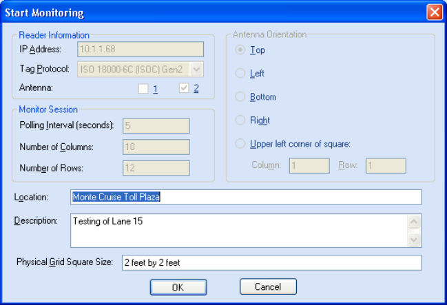
Appendix B AVI Lane Mapper
120
IDentity 4100 User Guide
Stop a Monitoring Session
1 To stop a monitoring session at any time, select:
Actions
→
Stop Monitoring Session
2 Or, to stop a Prompt or User Select Monitoring session, press the
Cancel
button on the message box or dialog displayed between polling
intervals.
Restart Monitoring Session
1 To restart a stopped monitoring session or start a session that was
loaded from a file, select:
Actions
→
Restart Monitoring Session
2 The following dialog is displayed:
This dialog is the same as shown when starting a new monitoring
session, except only the Location, Description, and Physical Grid
Square Size maybe edited.
If the session does not have the reader’s configuration information, the
utility will retrieve it from the reader before restarting the monitoring
session.
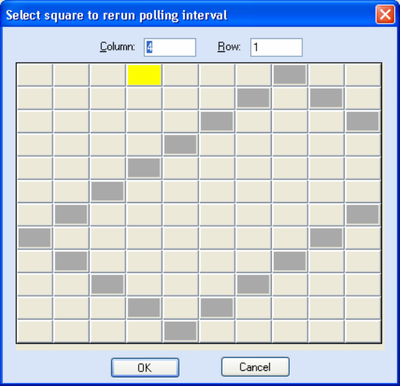
Appendix B AVI Lane Mapper
IDentity 4100 User Guide
121
Clear Session Data
1 To clear the results from a previous monitoring session, select:
Actions
→
Clear Session Data
2 If prompted, save the results before clearing the data.
Rerun Polling Interval (Method 1)
1 To rerun a polling interval for any given square, select:
Actions
→
Rerun Polling Interval
Note: A polling interval may only be rerun when there is no monitoring
session being executed.
2 The following dialog is displayed.
3 Enter the column and row of the square or click the square to
automatically fill in the column and row.
The current selected square is highlighted in yellow. Squares that
contain polling interval data will be highlighted in dark gray. Only
squares that contain polling interval data may be selected from this
dialog.
4 Double click a square to select that square, close the dialog, and
restart the polling interval for that square.
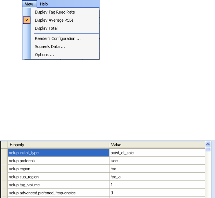
Appendix B AVI Lane Mapper
122
IDentity 4100 User Guide
Rerun Polling Interval (Method 2)
An alternate method to rerun a polling interval is as follows:
1 Double click on the desired square.
2 In the message box, press
Yes
to confirm rerunning the polling interval
for the selected square.
3 The polling period will start for that square. The data from the previous
polling interval will be lost when the polling interval is complete.
Changing the data displayed in a grid square
If a grid square is large enough, three types of data can be displayed in the
square:
h Tag read rate
h Total number of tags read
h Average RSSI.
You select which data is displayed from the
View
menu. Check marks are
displayed next to the selections. The selection can be changed at any time
and will be saved when exiting the application.
View the Reader’s Configuration
To view the Reader’s Configuration dialog, select:
View
→
Reader’s Configuration
The configuration is retrieved from the reader at the start of the Monitoring
Session or after a restart if the session data does not have any reader
configuration information. This information is saved with the test results
and also with exported results. The dialog values can not be modified.
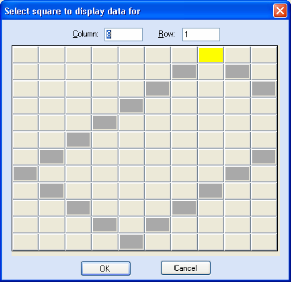
Appendix B AVI Lane Mapper
IDentity 4100 User Guide
123
Displaying the data from a given grid square
There are two ways for displaying the data from a polling interval for any
given grid square:
1 Click the square in the grid
2 Select
View
→
Square’s Data
.
3 This will display the following dialog.
4 Enter the column and row of the square or click the square to
automatically fill in the column and row.
The current selected square is highlighted in yellow. Squares that
contain polling interval data will be highlighted in dark gray. Only
squares that contain polling interval data may be selected from this
dialog.
5 Double click a square to select that square, close the dialog, and
display the square’s data.
6 The data is displayed in the boxes to the right of the main screen. If a
square has no data, these boxes will be emptied. If there is a
monitoring session currently running, the screen will be updated with
the last square’s data after a polling interval.
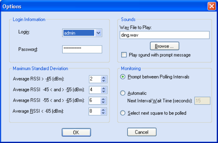
Appendix B AVI Lane Mapper
124
IDentity 4100 User Guide
Options
This is the dialog to modify the options used by the application. To view the
Options
dialog, select
View
→
Options
. These values will be saved across
application closings.
h Login – Login level to log into the reader as. This needs to be at least
admin. If this value is not specified or is incorrect, the application will
fail to start a monitoring session. The default Login is
admin
.
h Password – Password to use when logging into the reader. If this value
is not specified or is incorrect, the application will fail to start a
monitoring session. The default Password is
readeradmin
.
h Wav File to Play – Lists the sound file (.wav file) that is played when
Play sound with prompt message
is checked for Prompt and User
Select Monitoring Sessions or for Automatic Monitoring Sessions. If this
value is empty, no sounds are played. If a .wav file is specified, it needs
to currently exist. The default file
ding.wav
.
h Play sound with prompt message – Tells the application to play the
sound when the message box is displayed for a Prompt Monitoring
Session or when the dialog is displayed for User Select Monitoring
Session. The sounds is specified in the
Wav File to Play
field.
h Maximum Standard Deviation – Contains the maximum standard
deviation allowed based on the Average RSSI to determine a large
variance condition for a grid square. When the standard deviation is
greater than the value specified for the average RSSI, the square is
highlighted in red. The default values are listed in the table below.

Appendix B AVI Lane Mapper
IDentity 4100 User Guide
125
Average RSSI Maximum Standard Deviation
> -45 2
-45 < and > -55 4
-55 < and > -65 6
-65 < 8
h Prompt between Polling Intervals – Selects a Prompt Monitoring
Session. A message box to displayed at the start of the session and
between each polling interval. Press
OK
on the message box to start the
next polling interval. This is the default Monitoring Session type.
h Automatic – Selects an Automatic Monitoring Session. When the
monitoring session starts, the application waits for the amount of time
specified in the
Next Interval Wait Time
field before starting the polling
interval for the first grid square. If a sound file is specified, it will sound
at the end of the polling interval and the applications will wait again
until the next polling interval is started.
h Next Interval Wait Time – Amount of time the application will wait
between polling intervals in seconds. This value needs to be greater
than 1. The default for this option is 15.
h Select next square to be polled – Selects the User Selects Monitoring
Session. A dialog is displayed at the start of the session and between
each polling interval to allow you to select the next square to be polled.
Press
OK
on the dialog to start the next polling interval.
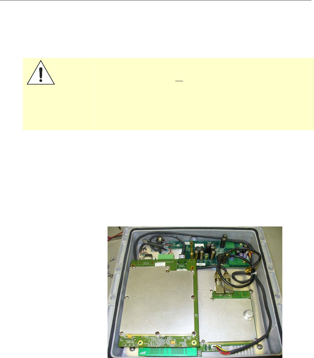
Appendix C Disposal of the IDentity 4100 Reader
126
IDentity 4100 User Guide
C Disposal of the IDentity 4100 Reader
Prior to disposing of the IDentity 4100 Reader, the battery must be
removed. The battery used in the IDentity 4100 is a Lithium / Manganese
Dioxide (Li/MnO2) type. This battery contains no measurable amounts of
mercury, lead, or cadmium.
Caution:
The procedure outlined in this appendix requires opening the IDentity 4100
Reader case in order to remove the battery prior to disposal. Opening the
case of the IDentity 4100 will void the warranty. In addition, opening the case
may adversely affect any future operation of the reader.
Never open the case of the IDentity 4100 Reader unless you are going to
remove the battery and dispose of the unit.
All disposal operations must be performed within local guidelines and laws. It
is the responsibility of the reader owner to ensure all local and regional laws
and regulations are followed for proper reader disposal.
To remove the battery, perform the following:
1 Remove the reader from service and disconnect any power, antenna,
and communication cables.
2 Remove the 16 Philips head screws securing the reader enclosure to
the antenna.
3 Separate the reader and antenna. An RF cable connects the two units.
4 Using an SMA connector wrench, remove the cable from the antenna
and set the antenna aside.
Appendix C Disposal of the IDentity 4100 Reader
IDentity 4100 User Guide
127
5 Remove the serial, digital I/O, and Ethernet cables from the digital
board.
6 Remove the nine screws securing the shield can to the digital board.
7 Remove the remaining screw securing the digital board to the chassis.
8 Remove the digital board from the enclosure and locate the battery
next to the LEDs.
9 Use a small flat-blade screwdriver to push the battery out of the holder.
10 Properly dispose of battery according to local and regional laws and
regulations.
11 Properly dispose of reader according to local and regional laws and
regulations.

Appendix D Reader Maintenance
128
IDentity 4100 User Guide
D
Reader Maintenance
D.1.
Antenna Radome Maintenance
The Sirit IDentity 4100 UHF RFID reader is a low maintenance device.
However, the user must ensure that any reader antenna radomes are kept
clean. Any build-up of foreign substances, water, or snow will degrade the
performance of the unit

Appendix E Error Handling
IDentity 4100 User Guide
129
E
Error Handling
This appendix provides a listing of errors and warnings. Where applicable, a
corrective action has been provided. Errors and warnings are listed by
severity (critical, major, warning) and then alphabetically. If an issue does
not resolve itself after taking the recommended corrective action, contact
Sirit support.
E.1.
Critical Errors
Critical errors are those errors that are likely to result in loss or severe
degradation of service. These errors must be addressed immediately.
Critical Error Event Description Corrective Action
MDM_ANTENNA_ FAILURE event.error.
antenna
Failed to set or change
antenna. Probably due to
un-terminated antenna
port.
Check condition of antennas,
connectors, and coax. Use
modem.antennas.perform_check() to
perform antenna check function to
determine if issue has been located.
MDM_CLOSED_LOOP_
POWER_CTL_FAIL
event.error.
radio
Internal RF power control
failed. May cause
inaccurate antenna power
output.
Perform reader reboot. If condition
persists, contact Sirit support.
MDM_OVERTEMP_ FAULT event.error.
environmental
High temperature
measured at modem
Determine cause of excessive reader
temperature and correct.
MDM_RC_CANT_SET_
FREQUENCY
event.error.
radio
Synthesizer problem tuning
to desired frequency.
Perform reader reboot. If condition
persists, contact Sirit support.
MDM_RC_NO_ ANTENNA event.error.
antenna
Failed to detect antenna.
Probably due to antenna
disconnected.
Check antenna connections, then
perform antenna check function.
MDM_SPI_NO_
RESPONSE
event.error.
communication
Modem has attempted to
communicate with a SPI
bus peripheral and
received no response.
Perform reader reboot. If condition
persists, contact Sirit support.
MDM_SYNTHESIZER_
LOCK_FAIL
event.error.
radio
Synthesizer can't lock to
desired frequency.
Perform reader reboot. If condition
persists, contact Sirit support.
MDM_TEMPERATURE_
SENSOR_FAIL
event.error.hw Temperature sensor
unable to detect
temperature.
Perform reader reboot. If condition
persists, contact Sirit support.
READER_INIT_FAILURE event.error.sw Main processor has failed
to successfully complete
the initialization process.
Perform reader reboot. If condition
persists, contact Sirit support.
SEEPROM_UNABLE_
TO_WRITE
event.error.hw Unable to write to
SEEPROM.
Perform reader reboot. If condition
persists, contact Sirit support.

Appendix C Reader Maintenance
130
IDentity 4100 User Guide
E.2.
Major Errors
Major errors are those errors that may result in loss or degradation of
service. These errors must be addressed as soon as possible.
Major Error Event Description Corrective Action
CHUNK_TOO_LARGE event.error.sw Unable to find enough
space in the SEEPROM.
Perform reader reboot. If condition
persists, contact Sirit support.
CHUNK_INVALID event.error.sw Unable to find valid data in
the SEEPROM.
Perform reader reboot. If condition
persists, contact Sirit support.
SEEPROM_INVALID_S
IZE
event.error.sw Unable to access SEEPROM
due to invalid size.
Perform reader reboot. If condition
persists, contact Sirit support.
CHUNK_NOT_ FOUND event.error.sw Unable to find valid data in
the SEEPROM.
Perform reader reboot. If condition
persists, contact Sirit support.
DATA_FORMAT_
ERROR
event.error.sw An error is detected in the
data format.
Perform reader reboot. If condition
persists, contact Sirit support.
DEVICE_INIT_
FAILURE
event.error.sw Error initializing a device in
the system.
Perform reader reboot. If condition
persists, contact Sirit support.
DEVICE_OPEN_
FAILURE
event.error.sw Unable to open device or
piped command.
Check memory and disk usage via
"Check Reader Status" webpage. If
"free_memory" is lower then 10 MBytes
or if filesystem:/apps or filesystem:/tmp
is higher than 90%, determine if
embedded application is improperly
using memory. If condition persists,
contact Sirit support.
INDEX_OUT_OF_
BOUNDS
event.error.sw Software is indexing
beyond end of array.
If condition persists, contact Sirit
support.
INVALID_ ARGUMENT event.error.sw Argument of an internal
command is invalid.
If condition persists, contact Sirit
support.
IOP_CONMGR_
INVALID_CMDRESP_
FD
event.error.
communication
Unknown command
channel being closed.
Perform reader reboot. If condition
persists, contact Sirit support.
IOP_CONMGR_
INVALID_EVENT_FD
event.error.
communication
Unknown event channel
being closed.
Perform reader reboot. If condition
persists, contact Sirit support.
IOP_HB_MODEM_
NOT_RESPONDING
event.error.hw Modem not responding to
keepalives from main
processor.
If condition persists, contact Sirit
support.

Appendix E Error Handling
IDentity 4100 User Guide
131
Major Error Event Description Corrective Action
IOP_IPRC_CRC_
ERROR
event.error.
communication
Communication from
modem processor had a
CRC error. May see at
bootup, since extra bytes
are sent from modem
processor during its boot
squence.
Usually caused by excessive processing
loading on the reader by external
entities. Determine if any external
process is continuously sending
command requests to the reader at a
high rate. If running an embedded
application, ensure that it is not
monopolizing the processor. If condition
persists, contact Sirit support.
IOP_IPRC_TIMEOUT event.error.
communication
Communication to modem
processor timed out. May
see at boot up, since
modem processor may take
a few seconds to boot.
Perform reader reboot. If condition
persists, contact Sirit support.
IOP_IPRC_TRY_AGAIN event.error.com
munication
No data available from the
modem processor.
Perform reader reboot. If condition
persists, contact Sirit support.
IOP_SPI_BAD_FILE event.error.
file_handling
Unable to open the
firmware file to be written
to the SPI FLASH.
Perform reader reboot. If condition
persists, contact Sirit support.
IOP_SPI_BAD_VERIFY event.error.
communication
Verification of data in SPI
FLASH failed.
Contact Sirit support.
IOP_SPI_INVALID_
FILE_FORMAT
event.error.
file_handling
The firmware file to be
written to the SPI FLASH
does not appear to be in
the proper hex format.
Contact Sirit support.
LICENSE_ERROR event.error.sw The main processor has
attempted a license
operation or import that
has failed.
Verify license file contains MAC address
of this specific unit. Verify the license
file has not been imported previously. If
condition persists, contact Sirit support.
MDM_ADC_DEVICE_
FAILURE
event.error.hw The ADC device on the
modem has generated an
error.
If condition persists, contact Sirit
support.
MDM_ANTENNA_
CHECK_FAILURE
event.error.
antenna
The reader cannot perform
an antenna check.
If condition persists, contact Sirit
support.
MDM_CALIBRATION_
DATA_MISSING
event.error.hw Unable to find valid
calibration data from the
reader SEEPROM.
Contact Sirit support.
MDM_CALIBRATION_
DATA_CORRUPT
event.error.hw Invalid calibration data
found on the reader
SEEPROM.
Contact Sirit support.
MDM_RECEIVER_FAIL
ED_SELFTEST
event.error.hw Reader self test failed. Contact Sirit support.
MDM_CNR_CLOSED_
LOOP_FAILED
event.error.radio CNR closed loop control
failed.
If condition persists, contact Sirit
support.

Appendix C Reader Maintenance
132
IDentity 4100 User Guide
Major Error Event Description Corrective Action
MDM_CNR_UPDATE_
WITH_TXOFF
event.error.sw An error is occurred when
CNR update with
transmission turned off.
If condition persists, contact Sirit
support.
MDM_FPGA_LOAD_
FAILURE
event.error.hw Unable to load FPGA device
on the modem.
If condition persists, contact Sirit
support.
MDM_FPGA_
RAMTEST_FAILURE
event.error.hw FPGA device on the modem
failed RAM test.
If condition persists, contact Sirit
support.
MDM_FPGA_RESET_
FAILURE
event.error.hw FPGA device on the modem
cannot be reset.
If condition persists, contact Sirit
support.
MDM_FPGA_TIMEOUT
_FAILURE
event.error.hw PPI bus stopped
unexpectedly
If condition persists, contact Sirit
support.
MDM_FPGA_TIMEOUT
_WARNING
event.error.hw Timeout waiting on FPGA
SPI bus.
If condition persists, contact Sirit
support.
MDM_ICM_ERROR event.error.
communication
An inter-core message
response on the modem
has an error.
Contact Sirit support.
MDM_ICM_TIMEOUT event.error.
communication
An inter-core message
response on the modem
has timed out.
Contact Sirit support.
MDM_INVALID_RX_
COMB_LENGTH
event.error.sw Invalid receiver filter length
is detected.
Contact Sirit support.
MDM_INVALID_RX_
Q_CHANNEL_COEFS
event.error.sw Invalid receiver filter
coefficient is detected.
Contact Sirit support.
MDM_IPRC_CRC_
ERROR
event.error.
communication
Modem has received
communication from main
processor which fails CRC
check. May see at boot up,
since processors may come
up (and start sending
messages) at slightly
different times.
Contact Sirit support.
MDM_IPRC_
OVERFLOW
event.error.
communication
Modem communication
buffer that receives data
from the main processor
has overflowed and data
has been lost.
Contact Sirit support.
MDM_IPRC_TRY_
AGAIN
event.error.
communication
Modem communication
buffer that receives data
from the main processor
has no full message yet.
Contact Sirit support.
MDM_L1_TX_PACKET
_TIMEOUT
event.error.
communication
Lowest level physical layer
transmit process timed out.
Contact Sirit support.

Appendix E Error Handling
IDentity 4100 User Guide
133
Major Error Event Description Corrective Action
MDM_LOW_VOLTAGE
_FAULT
event.error.
environmental
Low voltage on digital
portion of modem.
Verify correct operational voltage is
being supplied to reader. Verify power
supply voltages meet Sirit specifications.
If condition persists, contact Sirit
support.
MDM_MINIMUM_
GAIN_LIMIT
event.error.sw Receiver gain limit is
exceeded.
Contact Sirit support.
WIEGAND_FAILURE event.error.sw The main processor has
detected a failure related to
Wiegand application.
If condition persists, contact Sirit
support.
MDM_PPI_DEVICE_
FAILURE
event.error.hw The PPI interface has
generated an error.
Contact Sirit support.
MDM_RESET_
COMPLETE_MDM_
DOWN
event.error.hw The main processor has
reset the modem, but has
been unable to
communicate with it.
Perform reader reboot. If condition
persists, contact Sirit support.
MDM_RF_VOLTAGE_
FAULT
event.error.hw RF subsystem voltage
below acceptable level.
(May be seen when unit
powered off.)
Verify correct operational voltage is
being supplied to reader. Verify power
supply voltages meet Sirit specifications.
If condition persists, contact Sirit
support.
MDM_RX_TRAIN_
TIMEOUT
event.error.sw The modem has exceeded
the receiver training time
limit.
If condition persists, contact Sirit
support.
MDM_UNKNOWN_
PROTOCOL
event.error.sw The modem detected an
unsupported protocol.
If condition persists, contact Sirit
support.
MDM_UNKNOWN_
TX_INTERP_RATE
event.error.sw The modem detected an
unsupported transmit
interpolation rate.
Contact Sirit support.
MDM_UNKNOWN_
TX_TEST_MODE
event.error.sw The modem detected an
unsupported transmit test
mode.
Contact Sirit support.
MDM_UNKNOWN_TX
_WAVEFORM_TYPE
event.error.sw The modem detected an
unsupported transmit
waveform.
Contact Sirit support.
SPARSE_ARRAY_
BOUNDS_CHECK
event.error.sw Software attempted to
index beyong the limits of
the sparse array.
Contact Sirit support.
SYSLOG_INVALID_
LOG_LEVEL
event.error.sw Invalid level specified in C2
command for remote
syslog.
Verify the correct logging level of syslog
messages sent to the specified remote
syslog file server. If condition persists,
contact Sirit support.

Appendix C Reader Maintenance
134
IDentity 4100 User Guide
E.3.
Warnings
Warnings indicate that the system has detected an abnormality. Although
no action is required, the system should be monitored for further issues.
Warnings Event Description Corrective Action
IOP_CONFIG_FILE_
CORRUPT
event.warning.
file_handling
During the loading of a profile or auxiliary
configuration file, a file has been determined to
be corrupt.
None required.
IOP_EVENT_
INVALID_FORMAT
event.warning.
communication
Indicates an event with invalid format being sent
to the main processing system.
None required.
IOP_FILE_
TRANSFER_ERROR
event.warning.
file_handling
An attempt to move files in the main processing
system has failed.
None required.
IOP_SOCKET_
CREATE_FAILURE
event.warning.
communication
Indicates a failure to connect to the modem. None required.
IOP_SPI_NO_
ANSWER
event.warning.
communication
Indicates a failure to connect to the SPI bus. None required.
IOP_TMR_NO_
MORE_TIMERS
event.warning.sw Indicates a failure to find valid timers. None required.
KERNEL_FN_
FAILURE
event.warning.sw Indicates a failure in accessing the kernel
drivers.
None required.
LICENSE_EXPIRED event.warning.
license
A temporary license has expired. The licensed
feature has been disabled.
None required.
LICENSE_EXPIRING event.warning.
license
A temporary license is near expiration. The
licensed feature is still enabled.
None required.
LICENSE_WARNING event.warning.
license
A minor problem occurred during a license
import.
None required.
MALLOC_FAIL event.warning.sw Indicates a failure in allocating memory. None required.
MDM_ALL_
CHANNELS_BUSY
event.warning. radio The modem is unable to find valid channels. None required.
MDM_LBT_
CHANNEL_IS_
OCCUPIED
event.warning. radio The selected channel is occupied. None required.
MDM_NO_
AVAILABLE_
FREQUENCIES
event.warning. radio There are no frequencies available for
transmission which meet the LBT and/or
minimum-off-time requirements.
None required.
MDM_OVER_TEMP event.warning.hw The measured temperature is higher than the
warning threshold, but not high enough to cross
fault threshold.
None required.
MDM_
POWERMEASURE_
CLIPPED
event.warning. radio An error is detected in the power reading
process.
None required.

Appendix E Error Handling
IDentity 4100 User Guide
135
Warnings Event Description Corrective Action
MDM_RC_NO_
AVAILABLE_
FREQUENCIES
event.warning. radio The modem is unable to find valid frequencies. None required.
MDM_REFLECTED_
POWER
event.warning.
antenna
An antenna's return loss is lower than the
warning threshold, but not low enough to cross
the fault threshold.
None required.
MODULE_NOT_
INITIALIZED
event.warning.sw Indicates a failure in module initialization. None required.
NULL_POINTER event.warning.sw Indicates a failure in the pointer. None required.
SPARSE_ARRAY_
NULL
event.warning.sw Indicates a non-existent sparse array. None required.
SYMBOL_TABLE_
DEFAULT_INVALID
event.warning.sw Default value is invalid for the symbol. None required.
SYMBOL_TABLE_
FAILED_TO_
RESTORE
event.warning.
configuration
Indicates a failure in restoring the
configurations.
None required.
SYMBOL_TABLE_
FAILED_TO_SAVE
event.warning.
configuration
Indicates a failure to save the configurations. None required.
SYMBOL_TABLE_
OVER_
REGISTRATION
event.warning.sw Indicates duplicated registrations of the symbol. None required.
SYMBOL_TABLE_
WRONG_TYPE
event.warning.sw Data type is invalid for the symbol. None required.

Appendix C Reader Maintenance
136
IDentity 4100 User Guide
E.4.
Informational Messages
Informational messages describe various system events.
Message Event Description
AUX_PROCESS_FAILURE event.info The main processor has detected an
error in an auxiliary process.
IOP_EVENTS_DROPPED event.info The main processor has detected
events being dropped.
IOP_TAG_DB_OVERFLOW event.info The main processor has detected an
overflow in the tag database.
IOP_TMR_NO_EVENTS_
PENDING
event.info Indicates a timer signaled attention,
but there were no timer events
pending.
IOP_TMR_NOT_ACTIVE event.info Indicates a timer operation is being
performed on an expired timer.
ITEM_NOT_FOUND event.info Indicates a search failure.
MDM_RESET_COMPLETE event.info Modem reset is complete.
MDM_TEMP_RESUME event.info Indicates temperature reaching
resume value.
NO_AVAILABLE_CONNECTIONS event.info Indicates the maximum number of
command/response or event channels
have been exceeded.
OUT_OF_MEMORY event.info Indicates the maximum number of
events allowed for registration has
been reached.
READER_ENTER_DUTY_CYCLE event.info Indicates the reader entering the duty
cycle.
READER_INIT_SUCCESS event.info Indicates the reader successfully
initialized.
READER_RECOVERY event.info Indicates the reader recovery being
performed.

IDentity 4100 User Guide
137