3M Traffic Safety Systems ID5200 Identity 5200 RFID Transceiver User Manual Intended audience
3M Traffic Safety Systems Identity 5200 RFID Transceiver Intended audience
user manual


IDentity 5200
User Guide
V3.0
November 23, 2009
© 2009 Sirit Inc., All Rights Reserved. “Sirit”, the Sirit Design, “RFID by Sirit”, the RFID by Sirit Design and “vision beyond sight” are all
trademarks of Sirit Inc. All other trademarks are the property of their respective owners. Specifications are subject to change without notice.
This product is covered by one or more of the following patents: U.S. Patent No. 7,199,713, 7,209,040, 6,346,881, and 6,617,962.
Disclaimer and Limitation of Liability
The content of this manual is for information use only and is subject to change without notice. Sirit assumes no responsibility or liability for
any errors or inaccuracies that may appear in this publication. No part of this manual may be reproduced in any form or by any means,
electronic, mechanical, recording, or otherwise, without the prior written permission of Sirit.
Sirit products are not designed, intended, authorized or warranted to be suitable for life support applications or any other life critical
applications which could involve potential risk of death, personal injury, property damage, or environmental damage.
About Sirit
Sirit Technologies designs, develops, manufactures and sells Radio Frequency Identification (RFID) technology. Targeted at a diverse set of
markets RFID technology has become a core technology for applications including: electronic toll collection, access control, cashless
payment systems, product identification, and supply chain management systems including logistics, warehousing and manufacturing, and
asset management.
Head Office - Canada
372 Bay Street, Suite 1100
Toronto, Ontario, M5H 2W9 Canada
Tel: 416.367.1897
Fax: 416.367.1435
Toll Free: 1.800.498.8760
Email: mail@sirit.com
Sirit Technologies - US
1321 Valwood Parkway, Suite 620
Carrollton, Texas 75006 United States
Tel: 972.243.7208
Fax: 972.243.8034
Toll Free: 1.866.338.9586
Web: www.sirit.com

Preface
IDentity 5200 User Guide
i
Preface
Intended audience
This document is intended for professional installers setting up and
installing the IDentity 5200 reader. Before attempting to install, configure,
and operate this product, you should be familiar with the following:
h Microsoft® Windows® based software installation and operation
h Device communication parameters including Ethernet and serial
communications
h RFID reader configuration including antenna placement
h Basic digital input/output control
What’s in this guide
The information in this guide is presented as follows:
Chapter 1 – Reader Overview – This chapter provides a brief overview of the
IDentity 5200 hardware and software.
Chapter 2 – Reader Equipment Installation – This chapter describes how to
mechanically and electrically install the reader.
Chapter 3 – Reader Startup Tool (RST) Software Installation – This chapter
describes how to install the Microsoft Windows based RST application.
Chapter 4 – Reader Operation – This chapter describes how to initially test
a reader and how to operate deployed readers.
Chapter 5 – Reader Startup Tool (RST) – This chapter describes the RST
and the functions performed with this Microsoft Windows based application.
Chapter 6 – Embedded Reader Configuration Tool (RCT) – This chapter
describes the RCT and the functions perform with this application.
Chapter 7 – Configuring Digital Inputs and Outputs – This chapter describes
how to setup the reader’s digital inputs and outputs.
Chapter 8 – Specifications – This chapter detailed mechanical, electrical,
and environmental specifications for the IDentity 5200.
Chapter 9 – Safety Instructions – This chapter provides important safety
information about the reader. All users must read this section before
installing or operating this reader.
Appendix A – Disposal of the IDentity 5200 Reader – This appendix
provides instruction for removing the battery and disposing of the reader.
Appendix B – Reader Maintenance – This appendix provides instruction for
performing any reader maintenance activities.

ii
IDentity 5200 User Guide
What’s New in this Version
Version 3.0 of this manual updates the frequency and power specifications,
adds regulatory information, maintenance instructions, and updates the
RST and RCT descriptions.
Conventions used in this manual
The following conventions are used in this manual:
Bold courier font indicates code entered by the user
(values) within parentheses indicate parameters
(values)
in italics indicate user defined variables.
<n> indicates a variable number used in a function that can apply to
several different devices such as antennas or I/O ports.
WARNING:
Warnings advise the reader that a hazardous condition can be created by a
particular action that can cause bodily injury or extreme damage to equipment
ATTENTION:
This warning indicates that the device is susceptible to Electro Static
Discharge and appropriate precautions must be taken to avoid
equipment damage.
Caution:
Cautions advise the reader that a condition can be created by a particular action
that can cause equipment damage or result in equipment operation that violates
regulatory requirements.
NOTES
Important information
and other tips are
presented in light
blue boxes to the left
of the applicable
section.

Contents
IDentity 5200 User Guide
iii
Table of Contents
Chapter 1 – Reader Overview..................................................................................................................1
Reader Hardware...................................................................................................................................1
Reader Software....................................................................................................................................2
Chapter 2 – Reader Equipment Installation ..........................................................................................3
Mechanical Installation .........................................................................................................................3
Electrical Installation.............................................................................................................................5
Connecting the Serial Port.................................................................................................................6
Connecting and Configuring the Ethernet Port.................................................................................6
Connecting the External Antenna .....................................................................................................7
Connecting Digital Inputs/Outputs....................................................................................................7
Connecting the Power .......................................................................................................................7
Chapter 3 – Reader Startup Tool (RST) Software Installation.............................................................8
Installing RST Software........................................................................................................................8
Reader Startup.....................................................................................................................................10
Initial Reader Setup.............................................................................................................................11
Chapter 4 – Reader Operation...............................................................................................................15
Basic Operation with RST...................................................................................................................15
Deployed Reader Operation with RCT...............................................................................................17
Chapter 5 – Reader Startup Tool (RST).................................................................................................19
View Readers on the Network ............................................................................................................19
Configure Reader with the Setup Wizard ...........................................................................................20
View or Change the Reader’s Network Settings.................................................................................21
Reader Test Tool (RTT)......................................................................................................................22
RTT - General Page.........................................................................................................................22
RTT - Tag Performance Page..........................................................................................................24
RTT - Tag Management Page.........................................................................................................26
RTT - Macros Page .........................................................................................................................27
RTT - Event Handling Page............................................................................................................29
Reader Diagnostics Tool (RDT) .........................................................................................................30
RDT - Channel Statistics.................................................................................................................30
RDT - Alarms..................................................................................................................................31
RDT - Tag Report ...........................................................................................................................32
RDT - Spectrum Analyzer...............................................................................................................33
Contents
iv
IDentity 5200 User Guide
Chapter 6 – Embedded Reader Configuration Tool (RCT)..................................................................34
Basic Configuration ............................................................................................................................35
Configuration Page Header.............................................................................................................35
Manage Profiles ..............................................................................................................................36
Set Tag Protocol..............................................................................................................................37
Setup Ethernet/LAN........................................................................................................................38
Setup Serial Port..............................................................................................................................39
Setup Digital Accessories ...............................................................................................................40
Setup Antenna/Cables.....................................................................................................................41
Set Regulatory Mode (Region) .......................................................................................................42
Advanced Functions............................................................................................................................43
Firmware Management ...................................................................................................................43
Import/Export Configuration ..........................................................................................................44
Command Line................................................................................................................................45
Expert Configuration...........................................................................................................................46
Expert Configuration – Setup .........................................................................................................46
Expert Configuration – Tag ............................................................................................................47
Expert Configuration – Version......................................................................................................48
Expert Configuration – Information ...............................................................................................48
Expert Configuration – Communication.........................................................................................49
Expert Configuration – Antennas....................................................................................................49
Expert Configuration – Digital I/O.................................................................................................50
Expert Configuration – Modem ......................................................................................................51
User Application Management ...........................................................................................................52
Change Operating Mode .....................................................................................................................53
View Tags ...........................................................................................................................................54
Check Reader Status ...........................................................................................................................55
Review Logs .......................................................................................................................................56
Chapter 7 – Configuring Digital Inputs and Outputs...........................................................................57
Digital Inputs.......................................................................................................................................57
Digital Outputs....................................................................................................................................57
Digital I/O Monitoring and Control Scripts........................................................................................57
scan_trigger.py................................................................................................................................58
scan_trigger_timer.py......................................................................................................................58
signal_read.py .................................................................................................................................59
signal_read_crc_error.py.................................................................................................................60
rf_mon.py........................................................................................................................................60
Digital Input Alarm Generation..........................................................................................................61
Digital I/O Hardware Connection.......................................................................................................62
Contents
IDentity 5200 User Guide
v
Chapter 8 – Specifications.....................................................................................................................63
Reader Specifications (General)..........................................................................................................63
Reader Specifications (FCC)...............................................................................................................63
Environmental Specifications .............................................................................................................64
Power Supply Specifications...............................................................................................................64
RS-232 Specifications.........................................................................................................................65
Ethernet LAN Specifications ..............................................................................................................65
Antenna Cable Specifications .............................................................................................................65
External Antenna Specifications (FCC)..............................................................................................66
Bulkhead Connector/Interface Cable Pinout.......................................................................................67
Battery Specifications (Optional)........................................................................................................68
Chapter 9 – Safety Instructions.............................................................................................................69
Power Disconnect Device ...................................................................................................................69
RF Safety.............................................................................................................................................69
Electrostatic Discharge........................................................................................................................69
Regulatory Compliance.......................................................................................................................69
Appendix A – Disposal of the IDentity 5200 Reader..........................................................................70
Appendix B – Reader Maintenance.......................................................................................................72
Antenna Radome Maintenance ...........................................................................................................72
Contents
vi
IDentity 5200 User Guide
This page intentionally left blank.
1
2 3 4 5 6 7 8 9
Reader Overview
IDentity 5200 User Guide
1
Reader Overview
Reader Hardware
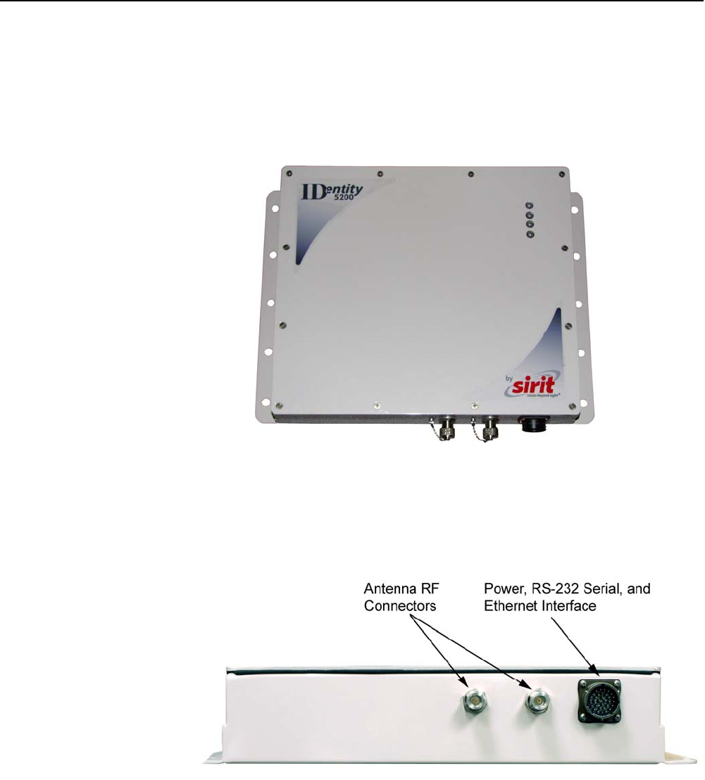
The IDentity 5200 is a multi-protocol, multi-regional Radio Frequency
Identification (RFID) System that operates in the 860 – 960 MHz UHF band.
The reader is configured at the factory to operate within a specific
regulatory region (for example: FCC Part 90).
Figure 1
IDentity 5200 UHF Reader
As shown in the following figure, the IDentity 5200 reader supports two
Tx/Rx antennas. The reader is equipped with both RS-232 serial and
Ethernet interfaces.
Figure 2
IDentity 5200 Power and I/O Connections
1
2 3 4 5 6 7 8 9
Reader Overview
2
IDentity 5200 User Guide
Reader Software
The IDentity 5200 is shipped with two software applications that you can
use to configure and control the reader.
Reader Startup Tool (RST)
The RST is a Microsoft Windows based application you install on your
computer. With RST, you can view all readers on your network. After
selecting a reader, you can modify its communication, network, and
operational parameters. You can also read tags, review tag data, perform
diagnostics, and upload new software. This RST is primarily intended for
initially configuring a reader prior to deployment. After deployment, use the
Embedded Reader Configuration Tool (RCT). Detailed information on the
RST is provided in Chapter 5.
Embedded Reader Configuration Tool (RCT)
This RCT is an embedded reader application that allows you to access your
readers across a LAN or WAN. Enter the IP address of the reader into your
Web browser and the RCT allows you to fully modify and operate the reader.
With the same functionality as the RST, this application allows you to modify
the reader’s communication, network, and operational parameters. You can
also read tags, review tag data, perform diagnostics, and upload new
software. This application is primarily intended for configuring and
managing deployed readers. Detailed information on the RCT is provided in
Chapter 6.
1
2
3 4 5 6 7 8 9
Reader Equipment Installation
IDentity 5200 User Guide
3
Reader Equipment Installation
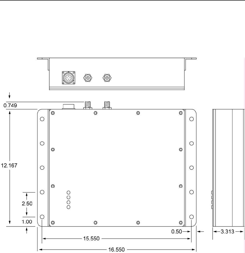
Mechanical Installation
The IDentity 5200 is available with two mounting flanges suitable for most
pole and wall mount applications. Any mounting surface must be able to
support a minimum static load of 11.0 pounds (5 kg) plus any additional
live load due to environmental conditions.
Figure 3
IDentity 5200 Mechanical Dimensions and Mounting Hole Locations

1
2
3 4 5 6 7 8 9
Reader Equipment Installation
4
IDentity 5200 User Guide
To mount the IDentity 5200 reader assembly, refer to Figure 3 and perform
the following:
1 Locate the Universal Mounting Bracket assembly and the Sun Shield.
2 Disassemble the Universal Mounting bracket. Retain all hardware.
3 Locate the Interface Cable.
4 Snake the bulkhead connector end of the Interface Cable through the
Universal Mounting Bracket and then through the Sun Shield.
5 Connect the cable to the reader’s bulk head connector and twist to lock
in place.
6 Install the Sun Shield on the four ¼”-20 studs located on the rear of
the reader. The Sun Shield will be spaced off the rear approximately
1/2” to allow for air flow.
7 Install the Universal Mounting Bracket on the four ¼”-20 studs.
8 Secure the Universal Mounting Bracket and Sun Shield to the reader
with the four ¼”-20 nuts, lock washers, and flat washers.
9 Install the Pole Mount Bracket to the Mounting Pole using the two U-
Bolts, four Keps Nuts, and four Flat Washers.
10 Adjust the Pole Mount to the proper height and tighten the hardware.
11 Assemble the Universal Mounting Bracket/reader assembly to the Pole
Mount.
12 Adjust the angle of the reader and tighten the hardware.
WARNING:
FCC Radiation Exposure Statement. The antennas used for this transmitter
must be installed to provide a separation distance of at least 1 meter from all
persons and must not be co-located or operating in conjunction with any other
antenna or transmitter.
1
2
3 4 5 6 7 8 9
Reader Equipment Installation
IDentity 5200 User Guide
5
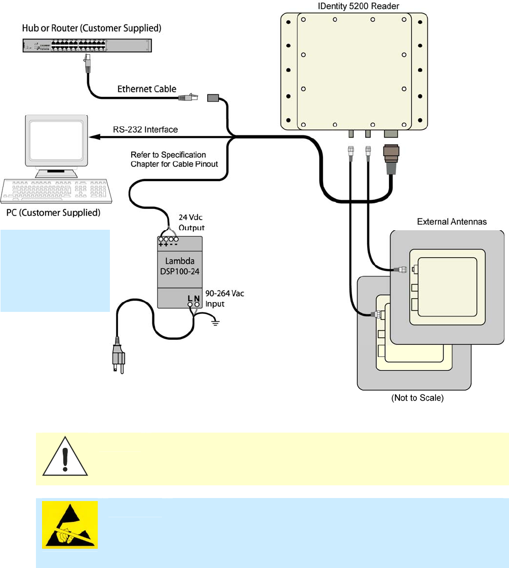
Electrical Installation
A general installation diagram is shown in the following figure. Refer to
Chapter 7 – Specifications for specific information.
Figure 4 IDentity 5200 Electrical Connections
Caution: The IDentity 5200 is designed to meet the regulatory requirements in those
jurisdictions in which it is offered. Changes or modifications not expressly
approved by Sirit Technologies for compliance could void the user's authority
to operate the equipment.
ATTENTION IDentity 5200 antenna ports may be susceptible to damage from static
discharge or other high voltage. Use proper Electrostatic Discharge
(ESD) precautions to avoid static discharge when handling or making
connections to the IDentity 5200 reader antenna or communication ports.
Equipment failure can result if the antenna or communication ports are
subjected to ESD.
Installation Notice
Installation of the
IDentity 5200 is only
to be performed by
trained, Sirit
approved personnel.

1
2
3 4 5 6 7 8 9
Reader Equipment Installation
6
IDentity 5200 User Guide
Connecting the Serial Port
The IDentity 5200 RS-232 serial port provides communication up to
115200 Baud. This port is accessed through the bulkhead connector
located on the rear of the reader. If you are using the serial port for reader
communication, connect a serial cable from the COM port on your PC to the
serial port on the reader. See Figure 2 for location of the connector.
Refer to the Chapter 8 – Specifications for details on the bulkhead
connector.
Connecting and Configuring the Ethernet Port
The IDentity 5200 Ethernet port is accessed through the bulkhead
connector located on the rear of the reader. If you are communicating with
your reader across a Local Area Network (LAN), connect an Ethernet cable
from your hub or router to the bulkhead connector. If you are connecting the
reader directly to a PC, you must use a crossover cable. See Note to the left.
By default, the reader is configured to use a DHCP server to obtain its IP
address and related information. In the event a DHCP server is unavailable,
the reader will boot with an IP address in the 169.254.x.x subnet.
In the absence of other readers on the same network, and if no other
network traffic is observed which references 169.254.1.1, the reader will
select that address; otherwise, it will select a random address on the
169.254.x.x subnet.
IP address settings can be changed using RST. Refer to the View or Change
the Reader’s Network Settings section in Chapter 5.
Refer to the Chapter 8 – Specifications for details on the bulkhead
connector.
Ethernet Cables
In most cases, you
will connect the
IDentity 5200 to a
network hub or
router. However, if
you are connecting
directly to a PC or
other computer,
you will need a
Crossover Cable
that swaps the Tx
and Rx signals.

1
2
3 4 5 6 7 8 9
Reader Equipment Installation
IDentity 5200 User Guide
7
Connecting the External Antenna
The IDentity 5200 supports two external Tx/Rx antenna. The maximum
antenna cable length is 10 meters. Connect the antenna to the antenna
port located on the bottom of the reader.
Refer to Chapter 7 – Specifications for specific information regarding the
external antenna and antenna cable.
Caution:
The IDentity 5200 is equipped with two external RF ports. If activated, these RF
ports must be properly terminated with a 50 ohm load or a functional UHF
antenna before power up. Always power down the reader before removing an
antenna or load from an RF port.
The maximum antenna cable length is 10 meters.
ATTENTION
The IDentity 5200 antenna port may be susceptible to damage from
static discharge or other high voltage. Use proper Electrostatic
Discharge (ESD) precautions to avoid static discharge when handling or
making connections to the IDentity 5200 reader antenna or
communication ports. Equipment failure can result if the antenna or
communication ports are subjected to ESD.
Connecting Digital Inputs/Outputs
The IDentity 5200 is equipped with a general purpose digital input/output
(I/O) port that provides four optically isolated 5-24 Vdc input signals and
four open-collector output signals. The digital inputs can be used as general
purpose inputs or to trigger the reader for tag reading. These inputs can be
configured to provide an external read trigger from proximity sensors, photo
switches, or other devices.
The digital outputs can be used as general purpose outputs, to indicate tag
reading activity, or to indicate the reader is transmitting (RF On). The
outputs can also be configured to trigger gates or other access control
devices.
Connecting the Power
The IDentity 5200 operates on 24 Vdc provided through the bulkhead
connector on the rear of the reader. Connect the power supply to the reader
and connect the power supply to your 100–240 Vac, 50-60 Hz power
source. Allow 30 seconds for the reader to initialize.
Refer to the Chapter 8 – Specifications for details on the bulkhead
connector.
1 2
3
4 5 6 7 8 9
RST Software Installation
8
IDentity 5200 User Guide
Reader Startup Tool (RST) Software Installation
Installing RST Software
The IDentity 5200 is delivered with a Microsoft Windows based application
called Reader Startup Tool (RST). You can use this application to initially
configure your reader as well as read and display tag data.
NOTE: The product CD provided with your reader contains two setup files: setup.exe and
IDentity_5200_RSTInstaller.msi. The first file, setup.exe, will fully check
your system configuration and load all required software including Microsoft .Net 2.0. If
you only want the RST application, use the IDentity_5200_RSTInstaller.msi
installation file. Note, however, the installation may abort if the required files are not
found on your system.
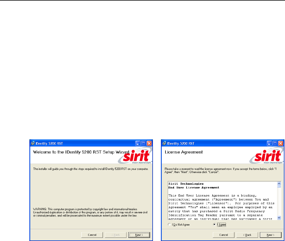
Install RST
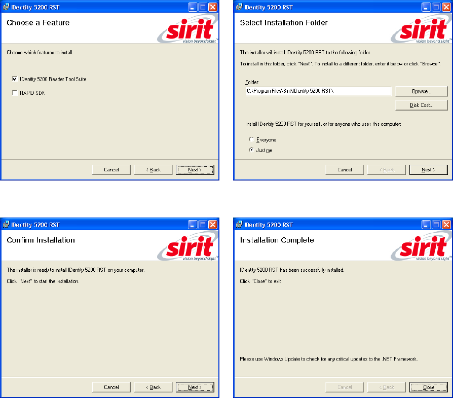
1 To install RST, load your product CD and double-click the setup.exe
or IDentity_5200_RSTInstaller.msi file:
2 Press
Next>
3 Read the License Agreement. Select
I Agree
and press
Next>
1 2
3
4 5 6 7 8 9
RST Software Installation
IDentity 5200 User Guide
9
4 Select if you want to install RST, the
RAPID SDK, or both.
5 Verify the path and folder where RST will
be installed. Press
Next>
.
5 Press
Next>.
6 After the installation completes, press
Close.
1 2
3
4 5 6 7 8 9
RST Software Installation
10
IDentity 5200 User Guide
Reader Startup
To begin using your reader, open the RST application.
Open RST
1 From your Windows desktop, select:
Start→Programs→Sirit→IDentity5200→Reader Startup Tool (RST)
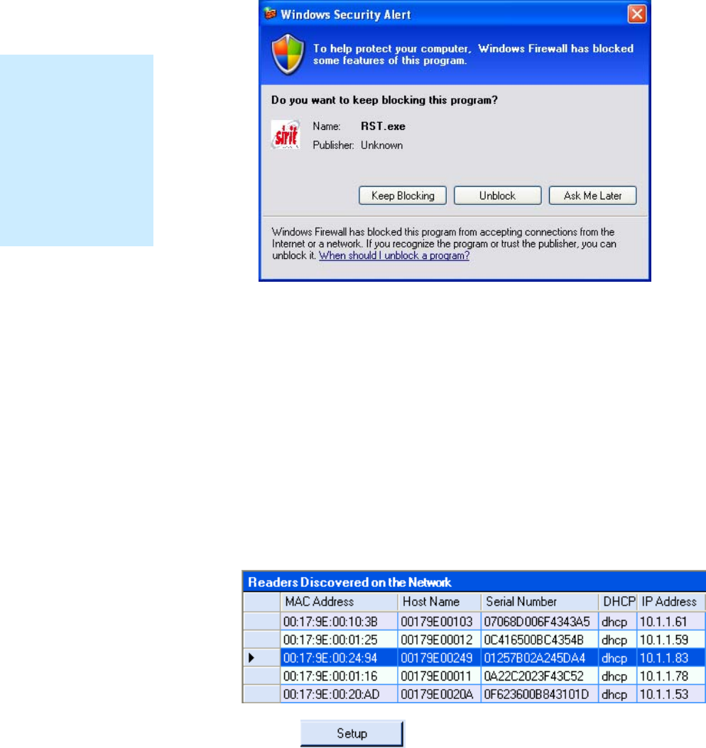
2 If this is the first time starting the RST application, you may receive a
Windows Security Alert. This warning indicates that the firewall is
blocking the RST application.
3 If the warning window is hidden under the RST windows, collapse the
RST window.
1 2
3
4 5 6 7 8 9
RST Software Installation
IDentity 5200 User Guide
11
4 Press
Unblock
.
5 Press
Refresh
on the RST
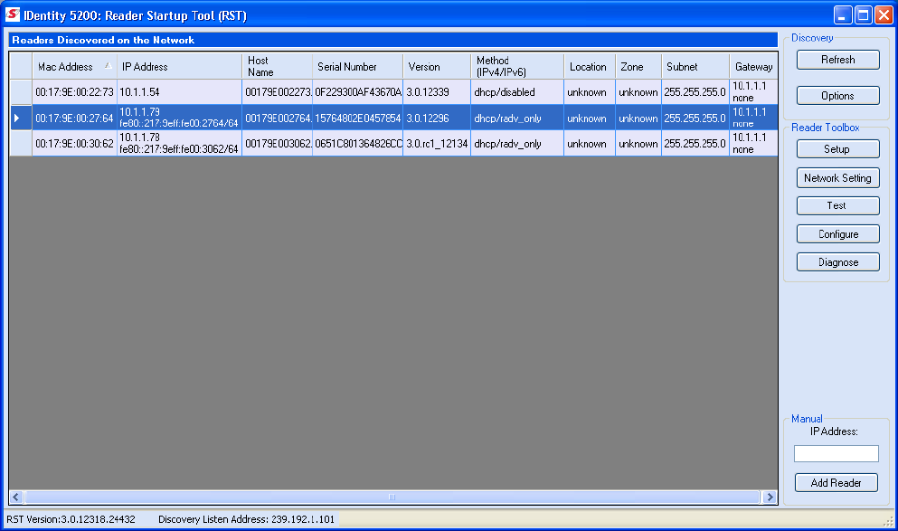
6 The RST main page will display any readers currently connected to the
network.
Initial Reader Setup
To configure a specific reader, perform the following:
Reader Setup
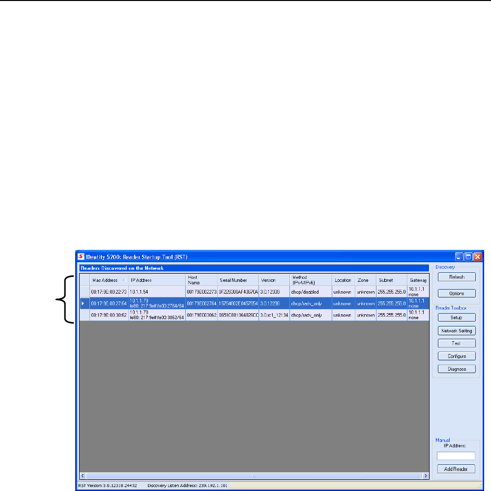
1 Select the reader on the main RST page by clicking the button to the
left of the reader Mac address.
2 Press the button on the RST window.
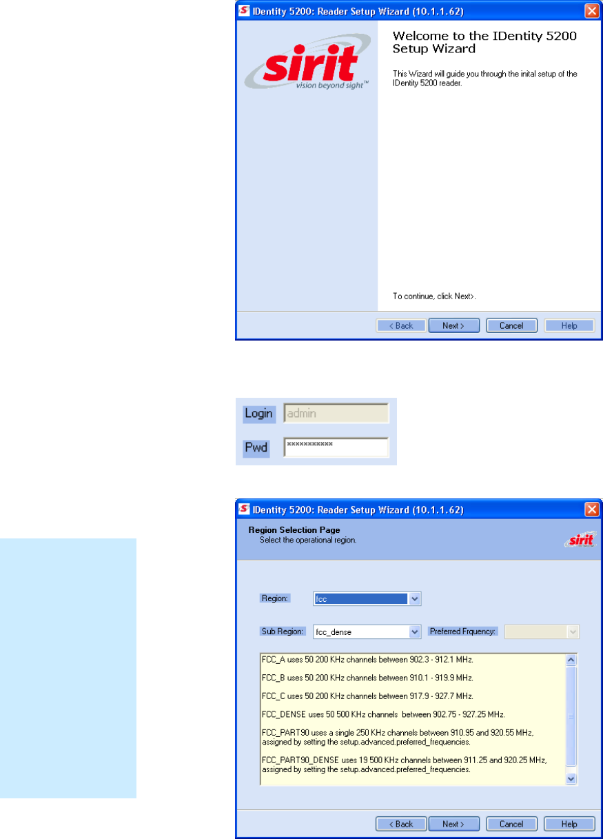
3 The IDentity 5200 Reader Setup Wizard (RSW) is displayed.
NOTE:
Earlier versions of
Microsoft Windows™
may not provide the
Security Alert popup.
IF RST does not
discover your reader,
check your Windows
Firewall/Security
settings.
1 2
3
4 5 6 7 8 9
RST Software Installation
12
IDentity 5200 User Guide
4 Press
Next>
and enter the Login (admin) and Password. If this is the
first time configuring your reader, enter: readeradmin.
5 After entering your Login and Password, press
Next>
.
Region Selection
The reader is
configured at the
factory to operate
within a specific
regulatory region. As
a result your region
selections may be
different from those
shown in this
manual.
Note that Region
Selection is not user
configurable.
1 2
3
4 5 6 7 8 9
RST Software Installation
IDentity 5200 User Guide
13
6 Select your Region and Sub Region and press
Next>
.
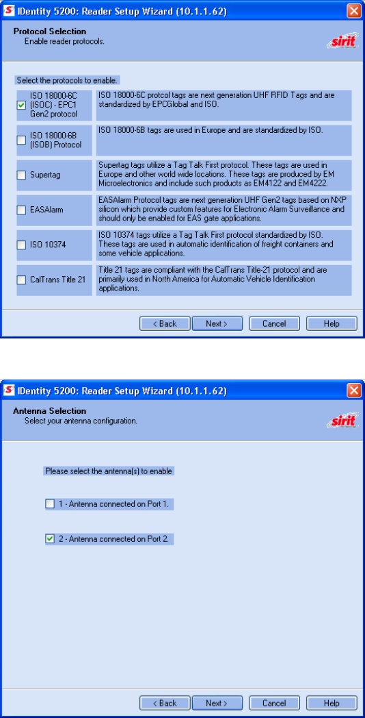
7 Select the protocols to read and press
Next>
.
8 Select the antennas you will be using and press
Next>
.
1 2
3
4 5 6 7 8 9
RST Software Installation
14
IDentity 5200 User Guide
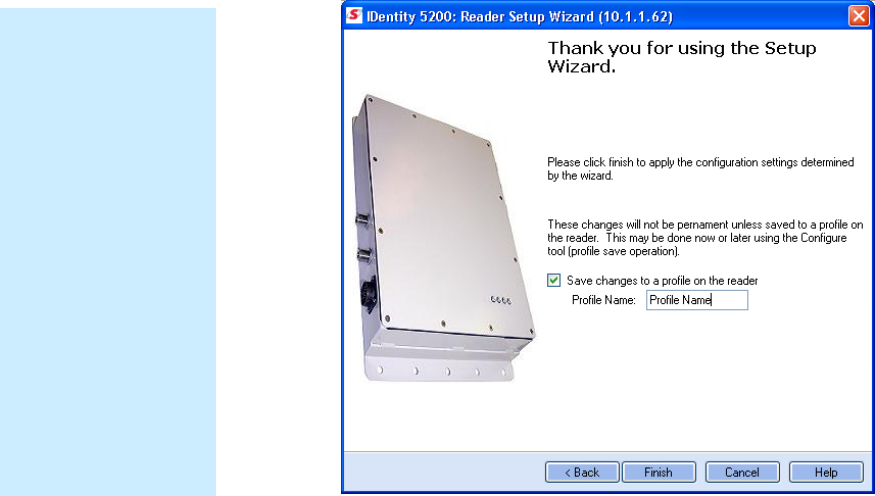
9 It is recommended that you save the reader setup as a profile.
Select
Save changes to a profile…
, enter a
Profile Name
, and press
Finish
to complete the initial reader setup. See Manage Profiles in
Chapter 6.
Saving Reader Setup
Reader setup
information should be
saved as a profile. In
the event that you
need to reboot or
power down a reader,
the reader setup can
be quickly reloaded
by loading the profile.
If you don’t save the
reader setup, you can
loose the information
if the reader is
rebooted.
Refer to the Manage
Profiles section in
Chapter 6 –
Embedded Reader
Configuration Tool.
1 2 3
4
5 6 7 8 9
Reader Operation
IDentity 5200 User Guide
15
Reader Operation
Basic Operation with RST
The IDentity 5200 can be operated either from the RST application or by
logging directly into the reader’s embedded Reader Configuration Tool
(RCT). To operate the reader from RST, perform the following:
Open RST
1 From your Windows desktop, select:
Start→Programs→Sirit→IDentity5200→Reader Startup Tool (RST)
2 Select a specific reader and press
Test
.
3 The Reader Test Tool (RTT) is displayed.
Customize the display
Customize your RST
display by clicking
and dragging the
columns. You can
also sort by column.
1 2 3
4
5 6 7 8 9
Reader Operation
16
IDentity 5200 User Guide
4 From the pull-down menu, select
Reader
→
Login
to login to the
reader. The initial password (
Pwd
) is readeradmin. See the
Advanced Setup section for details on changing the password.
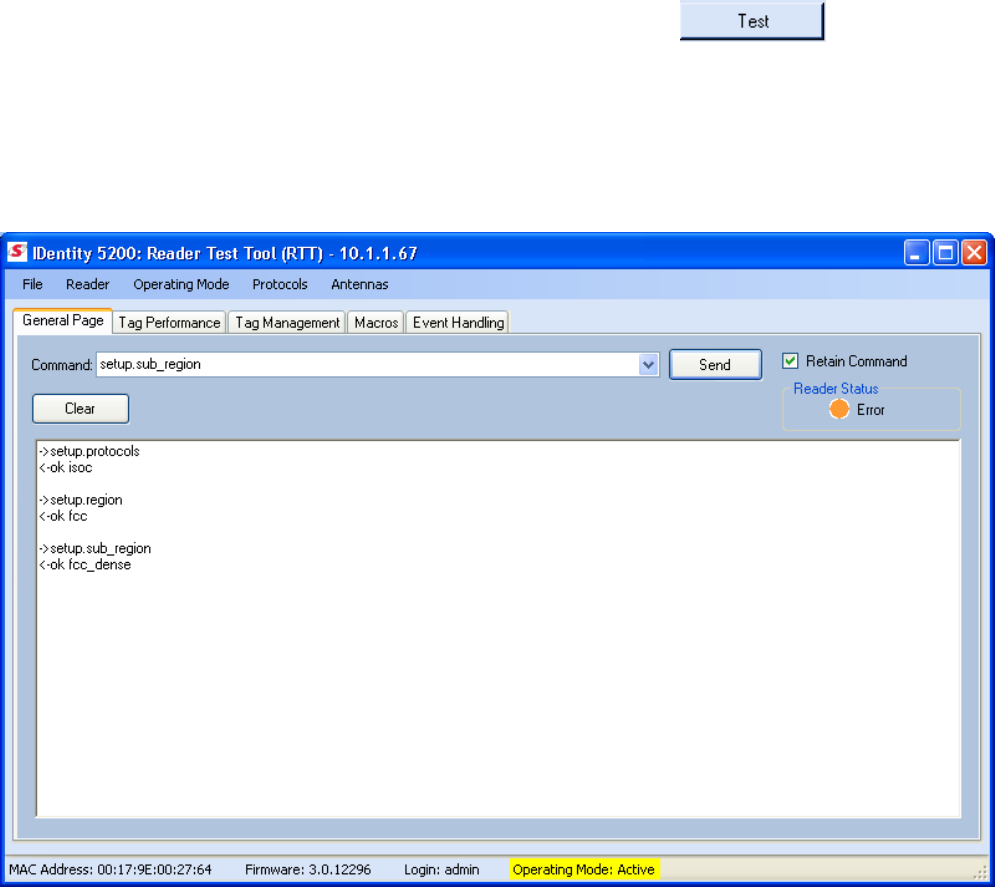
5 From the pull-down menu, verify the
Operating Mode
is set to
Active
.
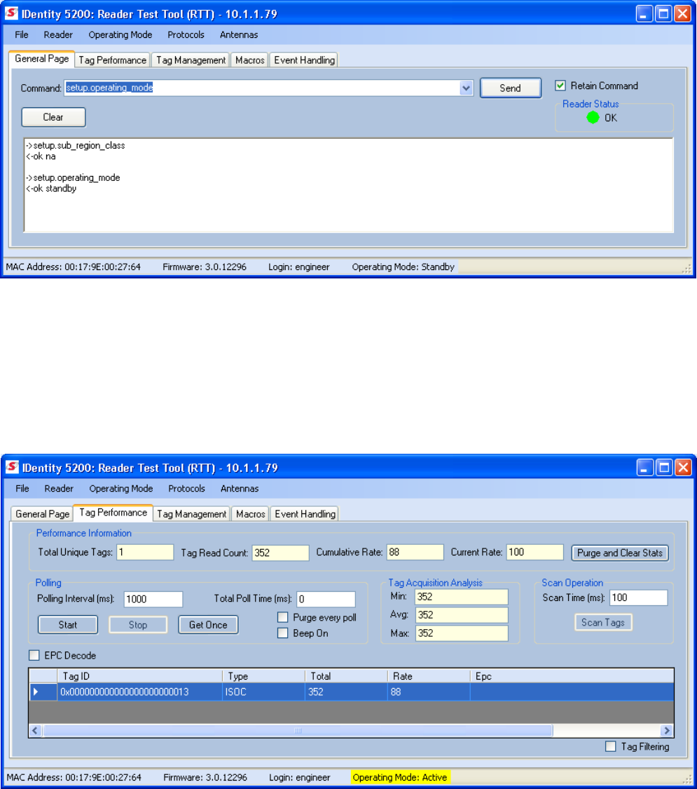
6 Select the
Tag Performance
tab and press
Start
.
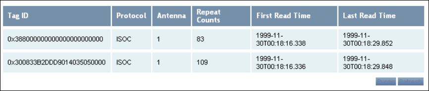
7 Place your tags in front of the antenna and verify the tags are read and
displayed as shown in the following figure.
1 2 3
4
5 6 7 8 9
Reader Operation
IDentity 5200 User Guide
17
Deployed Reader Operation with RCT
Once your readers are deployed, you can access them directly using the
embedded Reader Configuration Tool (RCT). To access a particular reader,
perform the following:
1 Enter the reader’s IP address into your Web browser or press the
button on the main RST page.
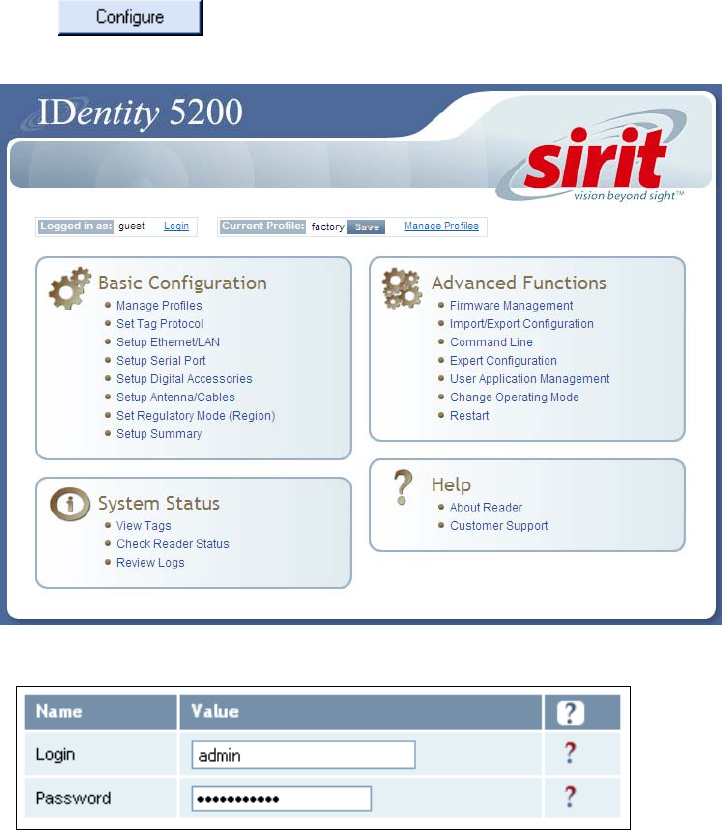
2 The reader’s RCT interface is displayed.
3 Log into the reader. Press
Login
for the login screen.
4 The default login is
guest
. If you need administrator privileges, login as
admin
and enter
readeradmin
as the password.
5 Press
Submit
.
6 Select
Basic Configuration
→
Setup Antenna/Cables
to configure the
antennas, gain, and power settings.
1 2 3
4
5 6 7 8 9
Reader Operation
18
IDentity 5200 User Guide
7 Select
Advanced Functions
→
Change Operating Mode
to verify the
reader is in the proper mode.
8 Select
Basic Configuration
→
Set Tag Protocol
to verify the reader is
configured for the proper tag protocol.
9 Press
System Status
→
View Tags
to view tag data.
10 If you need to configure your reader, refer to Chapter 7 – Reader
Configuration Tool for information on using RCT to adjust configuration
variables and parameters.
1 2 3 4
5
6 7 8 9
Reader Startup Tool
IDentity 5200 User Guide
19
Reader Startup Tool (RST)
The Reader Startup Tool (RST) provides an easy-to-use interface for the
IDentity 5200 configuration and operation functions. This Microsoft
Windows based application allows you to perform the following:
h View all readers on the network
h Launch the
Reader Setup Wizard
to initially configure a reader
h View and change a reader’s network settings
h Add a new reader to the network
h Launch
Reader Test Tool
to perform basic reader/tag operations
h Launch
Reader Diagnostic Tool
to view statistics, alarms, and reports
h Launch
Reader Configuration Tool
to perform detailed reader
configuration
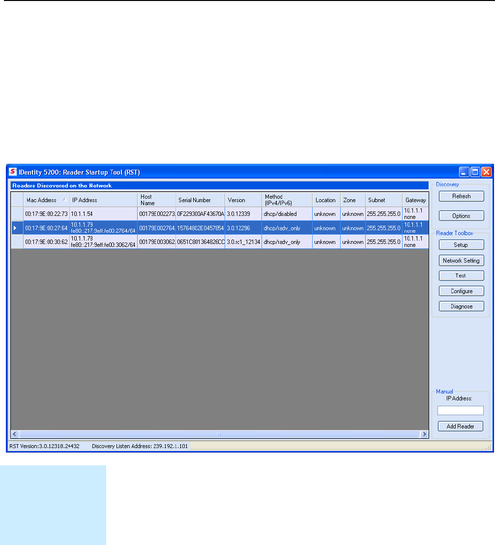
View Readers on the Network
When RST starts up, all readers currently connected to the network and
powered up are displayed.
Readers
On
Network
1 2 3 4
5
6 7 8 9
Reader Startup Tool
20
IDentity 5200 User Guide
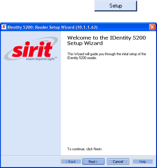
Configure Reader with the Setup Wizard
The Reader Setup Wizard is used to initially configure your reader for
operation. With this application, you can select the following:
h Regulatory region (fixed at factory) and sub-region
h Preferred Frequency (depending on regulatory settings)
h Number of antennas
To initially configure your reader perform the following:
1 From the RST main page, press the button. The Setup
Wizard is launched as shown.
2 Refer to Chapter 2 – Reader Configuration for detailed instructions on
using the Reader Setup Wizard.
1 2 3 4
5
6 7 8 9
Reader Startup Tool
IDentity 5200 User Guide
21
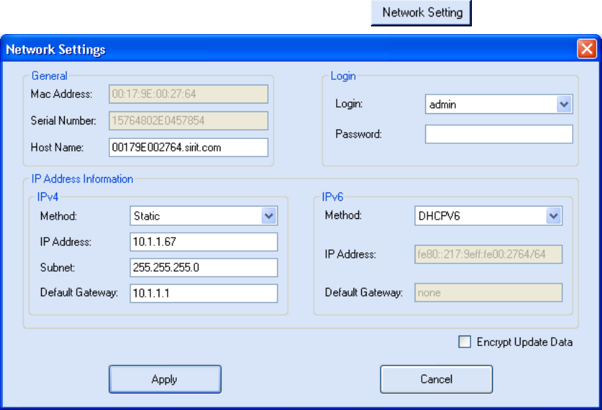
View or Change the Reader’s Network Settings
The Network Settings dialog allows you to change the IP Address, Subnet,
and Default Gateway of your reader. For readers with firmware version 2.0
or later, a password is required to make any changes.
1 From the RST main page, press the button.
2 Verify the
IP Address
,
Subnet
, and
Default Gateway
are correct.
3 If
DHCP
is selected these fields will be locked.
4 If changes are required, enter your
Login
and
Password
(V2.0 and
later).
5 Change the values and press
Apply
.
1 2 3 4
5
6 7 8 9
Reader Startup Tool
22
IDentity 5200 User Guide
Reader Test Tool (RTT)
The Reader Test Tool (RTT) is primarily designed for new users to test
reader operation and perform a few basic reader functions. With RTT, you
can perform the following:
h Read tags
h Issue commands to the reader and view the responses
h Run macros
h Observe reader events
To access the Reader Test Tool, press the button on the
main RST page.
RTT - General Page
The
General Page
allows you to issue commands to the reader and view
any responses. You can also change the operating mode, active protocols,
and select antennas.
1 2 3 4
5
6 7 8 9
Reader Startup Tool
IDentity 5200 User Guide
23
RTT has several pull-down menus for logging into the reader, selecting the
operating mode, activating protocols, and selecting antennas:
Reader
Login
– Select to enter your login user name. The default login is
guest
. If
you need administrator privileges, login as
admin
. Enter
readeradmin
as the
password if you logged in as
admin
.
View Error Log
– Select to view any errors generated by the reader. Errors
are displayed in a separate window. Use Notepad to edit the error list.
Clear Error/Warning Condition
– Select to clear the reader of any errors
and warnings.
Operating Mode
Active
– Reader is continuously attempting to singulate tags and
automatically reports any singulated tag via an asynchronous event
notification on the event channel.
Standby
– Reader is not transmitting any energy, unless processing a tag
related command. The RF transmitter is enabled at the beginning of the
command processing, any protocol operations required for the command
are performed, and then the RF transmitter is turned back off.
Protocol
Select the protocol(s) for the tags you will be reading.
Antenna
Select the ports that have antennas connected. You can also select the
antenna multiplexer sequence. Select
Mux Sequence
and enter the order
that antennas are to be activated.
1 2 3 4
5
6 7 8 9
Reader Startup Tool
24
IDentity 5200 User Guide
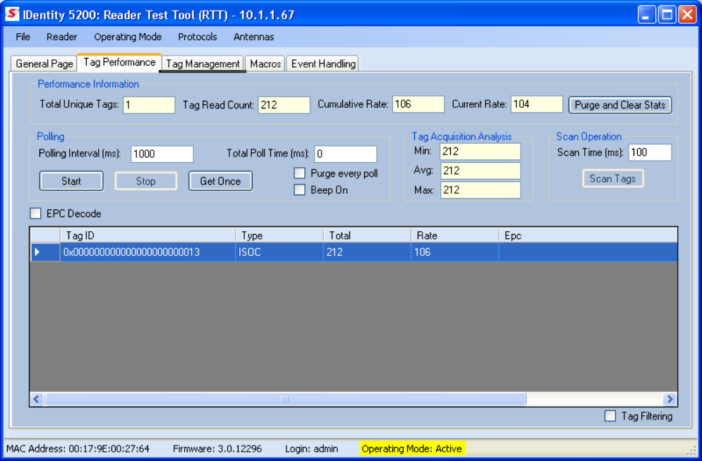
RTT - Tag Performance Page
The
Tag Performance
page is used to test the reader performance. This
page is useful for range (distance) testing and to verify the RF field size.
To initiate a timed test, enter the length of test (in ms) into the
Total Poll
Time
field. For example, to verify to number of tags read in a 30-second
interval, select
Active
Operating Mode, enter 30000, and press the
Start
button. The test will complete after 30 seconds and the output statistics are
updated for the poll time.
Output statistics are read-only and include: Total Unique Tags, Tag Read
Count, Cumulative Rate, Current Rate.
Detailed descriptions of the various
Tag Performance
fields and functions
are provided in the following sections.
1 2 3 4
5
6 7 8 9
Reader Startup Tool
IDentity 5200 User Guide
25
Tag read controls are provided by the
Polling
and
Scan Operation
blocks.
Use the
Polling
controls when the reader is in active mode. Use the
Scan
Operation
controls when the reader is in standby mode.
Tag and reader performance data is provided in the
Performance
Information
and
Tag Acquisition Analysis
blocks.
Performance Information
Total Unique Tags
– Number of unique tags in the tag database.
Tag Read Count
– Total number of tags reader (including repeat reads).
Cumulative rate
– Cumulative read rate in tags/second since the
Start
button was pressed.
Current rate
– Current read rate in tags/second.
Purge and Clear State
– Press to clear the current display and reset the
statistics reporting.
Polling
Polling Interval –
Amount of time (ms) to wait between each poll for data.
Polling Interval –
Total amount of time (ms) to poll for data (1 to 10 sec).
Start –
Click this button to poll the tag database every
Polling Inte
rval (ms)
for a total time of
Total Polled Time (ms).
Do not set the interval less than
500. If Total Polled Time is set to 0, polling continues indefinitely.
Stop –
Click this button to stop automatic polling.
Get Once –
Click this button to retrieve the current information from the
reader’s tag database.
Purge every poll –
Check this option to purge the reader’s tag database
after each poll. Refer to the INfinity 510 Protocol Reference Guide for more
information on the tag database.
Beep On –
Indicates current read rate with audible tone.
Tag Acquisition Analysis
The
Tag Acquisition Analysis
fields provide the minimum, maximum, and
average number of times each tag was read. For example, assume five tags
(A, B, C, D, and E) are read 107, 59, 223, 187, and 94 times respectively.
The displayed values are as follows:
Min
= 59
Avg
= 134
Max
= 223
Scan Operation
Scan time (ms)
– Enter the duration of reader operation in milliseconds.
After this time expires, the tag information is displayed.
Scan Tags
– Press this button to activate the reader.
1 2 3 4
5
6 7 8 9
Reader Startup Tool
26
IDentity 5200 User Guide
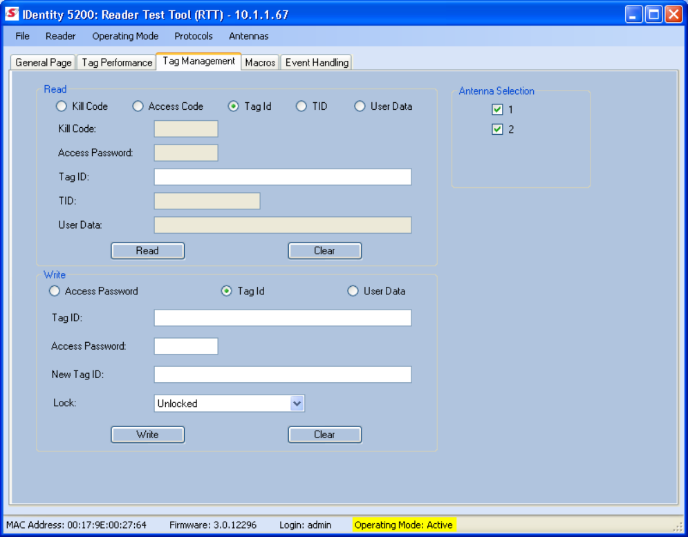
RTT - Tag Management Page
The
Tag Management
page is used for reading and writing individual fields
on a single tag. The
Read
button will cause the reader to singulate and read
a tag in the selected antennas' RF field.
Specific fields you can read include Kill Code, Access Code, Tag ID, TID, and
User Data.
The
Write
button will write specific data to the tag including Access
password, Tag ID, as well as allow you to lock the tag.
1 2 3 4
5
6 7 8 9
Reader Startup Tool
IDentity 5200 User Guide
27
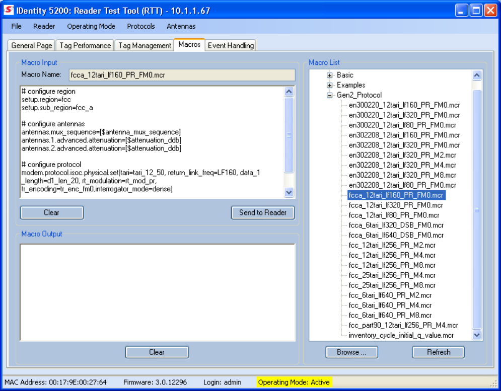
RTT - Macros Page
The
Macros
page allows the reader to manage macro files. The macros are
provided by Sirit or can be written by the end user. Some of the macros
provided are dependent on the operating region of the reader.
A macro (script or command file) is a text file that contains one or more
reader commands. These commands are used to configure the reader to a
known configuration. The Macros can contain variables. These variables are
resolved by a dialog box (
Macro Variables
) that appears when the
Send to
Reader
button is selected. The syntax of a variable is:
[$variable_name]
During execution, the variable is replaced with user entries in the
Macro
Variables
dialog box. Macros can be edited with any text editor including
Windows Notepad.
1 2 3 4
5
6 7 8 9
Reader Startup Tool
28
IDentity 5200 User Guide
Macro Input sub-window
The
Macro Input
window shows the current script that will be sent to the
reader when the
Send to Reader
button is selected. The text in the
Macro
Input
window can be edited prior to being sent to the reader. The
Save
Macro File
button will prompt you for a filename to save the text to a file.
Macro Output sub-window
The
Macro Output
window is updated after the
Send to Reader
button is
selected. Look at this window to verify that each command line in a script
executed correctly. Look for the
−−>> ok
response from the reader for each
command line.
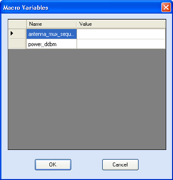
Macro Variables Dialog box
When a macro is sent to the
reader, the values for variables
must be resolved via this Windows
Dialog box. You can
[tab]
to each
value field and enter the desired
value.
For example, one macro can be
used for two different applications
by using variables for antenna
selection and transmit power.
Macro Example
To configure the reader for four-antenna portal operation, send the following
macro (
en302208_12tari_if320_PR_FMO.mcr
):
# configure region
setup.region=etsi
setup.sub_region=en302208
# configure antennas
antennas.mux_sequence=[$antenna_mux_sequence]
antennas.2.conducted_power=[$power_ddbm]
# configure protocol
modem.protocol.isoc.physical.set(tari=tari_12_50,
return_link_freq=LF320, data_1_length=d1_len_20,
rt_modulation=rt_mod_pr, tr_encoding=tr_enc_fm0,
interrogator_mode=dense)
1 2 3 4
5
6 7 8 9
Reader Startup Tool
IDentity 5200 User Guide
29
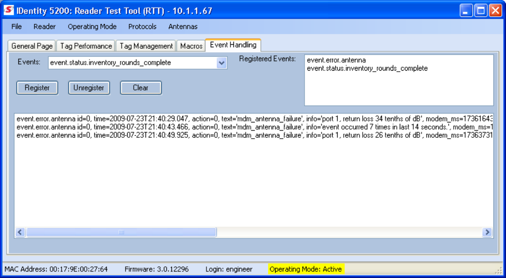
RTT - Event Handling Page
The
Event Handling
page allows you to register for Reader Events. After
registration, events will be displayed as they occur in the window. Individual
events or a group of events can be registered. Events are displayed with the
newest event on the top line of the window. The least recent event will scroll
to the bottom of the window.
For detailed information on individual events, refer to Chapter 18 – Events
Namespace of the IDentity 5200 Protocol Reference Guide.
Registering for an individual event
To register for an individual event, either type the event name or select an
event from a pull-down list.
Registering for a group of events
Registering for
event.error
events, will cause the reader to autonomously
send all events in the
event.error
namespace to the RTT program and be
displayed in the window of this page. Enter
event.error
in the
Events:
field
and press the
Register
button. The
Clear
button can be selected at any
time to clear the window.
1 2 3 4
5
6 7 8 9
Reader Startup Tool
30
IDentity 5200 User Guide
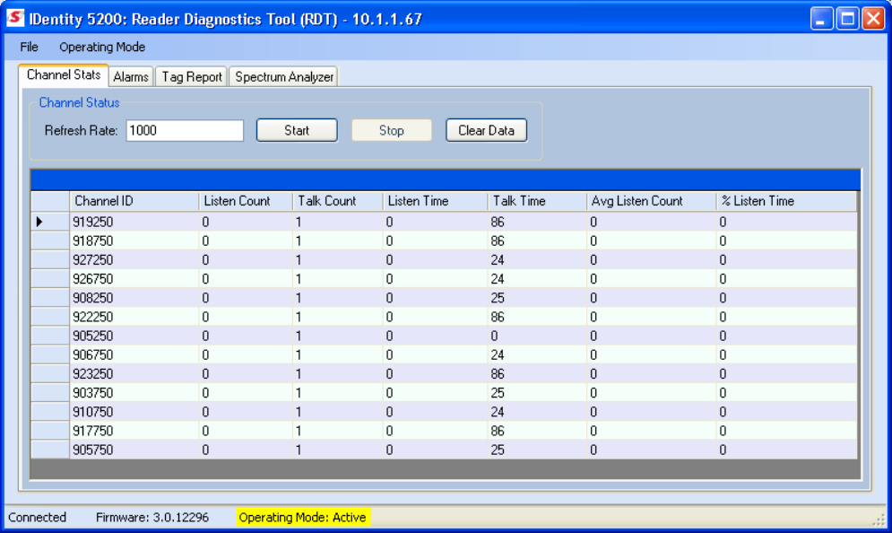
Reader Diagnostics Tool (RDT)
The Reader Diagnostic Tool (RDT) is to be used by Sirit trained technicians
to troubleshoot and diagnose various reader issues.
RDT - Channel Statistics
The Channel Stats page shows details of channel changes. This page is
typically used to observe ETSI 302-208 Listen before Talk (LBT) behavior. It
can also be used to observe FCC and other regional behavior.
1 2 3 4
5
6 7 8 9
Reader Startup Tool
IDentity 5200 User Guide
31
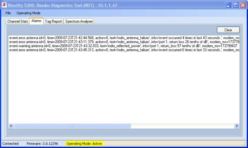
RDT - Alarms
The
Alarms
page is used to capture autonomous alarms generated by the
reader during normal operation. The alarms are defined as autonomous
reader events for the following namespaces:
event.error
event.warning
1 2 3 4
5
6 7 8 9
Reader Startup Tool
32
IDentity 5200 User Guide
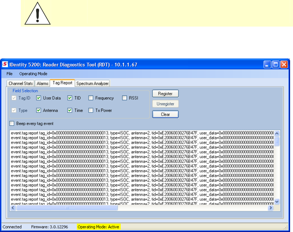
RDT - Tag Report
The Tag Report page is used to view specific information for each tag
singulation. This feature provides detailed attributes of tag singulations
such as tag power (RSSI) and on which antenna that tag singulated.
Caution:
Use of this tool can adversely affect tag reader performance, particularly if many
tag fields are enabled. Use the RTT->Tag Performance page for normal tag
performance testing.
1 2 3 4
5
6 7 8 9
Reader Startup Tool
IDentity 5200 User Guide
33
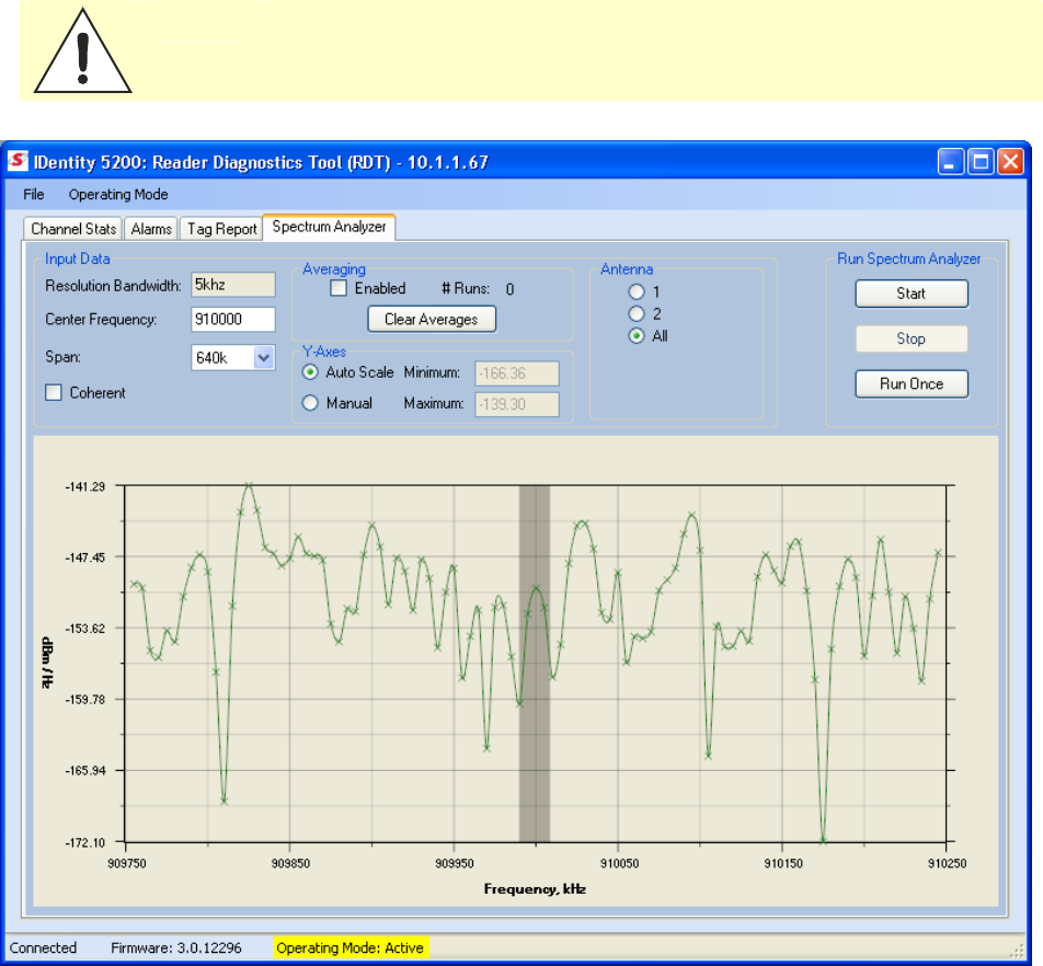
RDT - Spectrum Analyzer
The Spectrum Analyzer allows you to examine the spectral composition of
the radio waves in your surrounding environment. This feature provides a
graphical representation of the current spectral RF noise in units of dBm
with a range of 0 to -120 dBm. This feature is intended for expert users to
verify RF environmental conditions during an installation.
Set the
Center Frequency
and
Span
fields to view the desired range of
frequencies. The Spectrum Analyzer settings are saved and are recalled
when RDT is restarted the next time.
Caution:
Using this feature during normal reader operation can significantly degrade tag
reading performance.
1 2 3 4 5
6
7 8 9
Reader Configuration Tool
34
IDentity 5200 User Guide
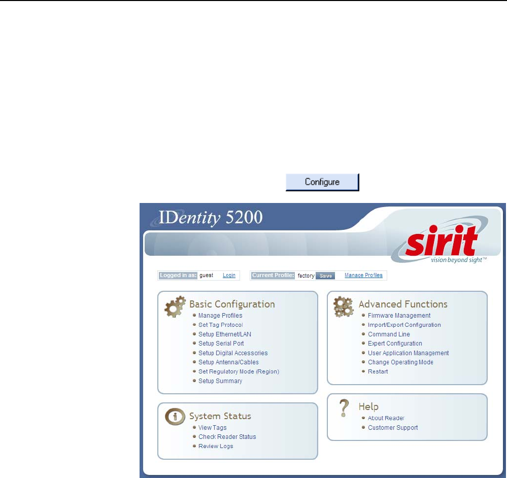
Embedded Reader Configuration Tool (RCT)
The Embedded Reader Configuration Tool (RCT) allows you to access your
reader across a LAN or WAN by entering the reader’s IP address into your
web browser. With the RCT, you can fully configure your reader for operation
in a variety of applications and environments. With this application, you can
perform the following:
h Basic Configurations
h Advanced Configurations
h Check System Status
h Access the online Help
To access the RCT, press the button on the main RST page.

1 2 3 4 5
6
7 8 9
Reader Configuration Tool
IDentity 5200 User Guide
35
Basic Configuration
With the Basic Configuration functions you can manage reader profiles and
setup the Ethernet, serial port, digital accessories, antennas, and regulatory
modes.
Configuration Page Header
Each page displayed by the RCT has the following header.
This header provides pull-down menus for each of the configuration
function categories. Additional functions include the user login and the
currently loaded reader profile.
Login/Logout
The reader’s default user level is
guest
. However, a user can login as
admin
. If not logged in as
admin
, the default level is always
guest
.
The guest login level provides read-only access to the reader. Clients that
login in at the guest level can read the settings of the reader and can
access the tags that the reader has inventoried. Clients at this level cannot
change the configuration of the reader.
The admin login level provides read-write access to the reader. Clients that
login in at the admin level can read and write the settings of the reader and
can access the tags that the reader has inventoried.
After logging in as
admin
, the
Logout
button logs you out of the reader.
Logging out automatically sets the login level to guest.
Profile
Profile is the currently active profile in the reader. Refer to the Manage
Profiles section for detailed information on reader profiles.
Save
The Save button saves the reader's current configuration to the specified
profile. Refer to the Manage Profiles section for detailed information on
reader profiles.
Manage Profiles
This link allows you to list, save, and delete profiles. Refer to the Manage
Profiles section for detailed information on reader profiles.
Profile Names
The profile name
factory is reserved
and cannot be used.
This profile is a read
only profile.
1 2 3 4 5
6
7 8 9
Reader Configuration Tool
36
IDentity 5200 User Guide
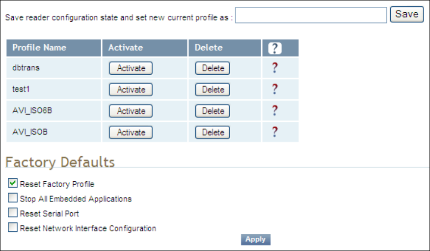
Manage Profiles
The reader’s configuration is stored in a profile. A profile contains the
setting of all the configuration variables in the reader. The reader can
support up to 8 unique profiles. Detailed information about reader profiles
is provided in Chapter 4 – Reader Behavior of the IDentity 5200 Protocol
Reference Guide.
The
Manage Profiles
page provides a list of all profiles stored in the reader.
Save a Profile
To save your current reader configuration under a new profile, enter a
profile name and press
Save
. The new profile will appear in the Profile
Name list. Profile names must consist of the characters A - Z, a - z, 0 - 9, '-'
or '_' and must be between 1 and 32 characters in length. The reader can
store up to 8 different profiles.
Activate a Profile
To activate a previously saved profile, press the
Activate
button beside the
profile name. The selected profile will be loaded into the reader.
Delete a Profile
To delete a previously saved profile, press the
Delete
button beside the
profile name. This is a destructive operation. Once a profile is deleted, it
cannot be recovered.
1 2 3 4 5
6
7 8 9
Reader Configuration Tool
IDentity 5200 User Guide
37
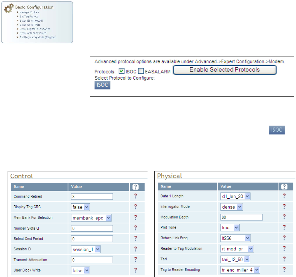
Set Tag Protocol
This
Set Tag Protocol
page consists of two forms. The first form (top) allows
you to select which type of tags the reader will acquire or the type of
protocol(s) to utilize on the air interface. Currently, the reader can operate
with either ISO18000-6C (ISOC), ISO18000-6B (ISOB), SuperTag,
ISO10374, EASALARM, or any combination.
Select the check box for the protocol(s) to enable and then press
Enable
Selected Protocols
to activate the protocol.
To configure protocol level parameters, select the protocol button .
The protocol level parameters are divided into two categories: control and
physical. Control parameters configure the protocol control. Physical
parameters configure the physical air interface for the protocol.
For detailed information on each of the Control and Physical parameters,
refer to Chapter 15 – Modem Namespace of the IDentity 5200 Protocol
Reference Guide. Parameter descriptions are provided in the
modem.protocol.isoc.control
and
modem.protocol.isoc.physical
configuration variable sections.
1 2 3 4 5
6
7 8 9
Reader Configuration Tool
38
IDentity 5200 User Guide
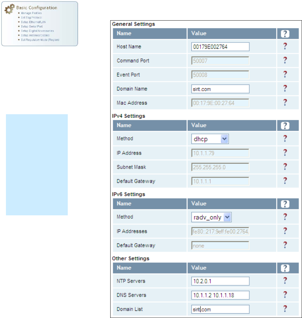
Setup Ethernet/LAN
The Setup Ethernet/LAN page allows you to configure the network interface
of the reader.
NOTE:
Always record the
IP, Mac, subnet,
and default
gateway addresses
for your readers
and keep this data
in a safe location.
You can use this
data to reconfigure
the network in the
event of application
failure or data loss.
1 2 3 4 5
6
7 8 9
Reader Configuration Tool
IDentity 5200 User Guide
39
General Settings
allow you to specify the host and domain name of the
reader. The Command and Event Ports are also shown and are read-only.
IPv4/IPv6 Settings
allow you to configure the reader’s IP address. If the
reader is to automatically acquire its IP address, subnet mask and default
gateway from a DHCP server, select
Enable DHCP
. To manually specify this
information, deselect
Enable DHCP
and fill in the desired IP address,
subnet mask and default gateway.
Other Settings
allow you to configure the NTP servers the reader can
contact to obtain the current time, DNS servers the reader can contact for
domain name resolution, and the Domain list to resolve names to IP
addresses.
Enter all the required information and press
Submit
.
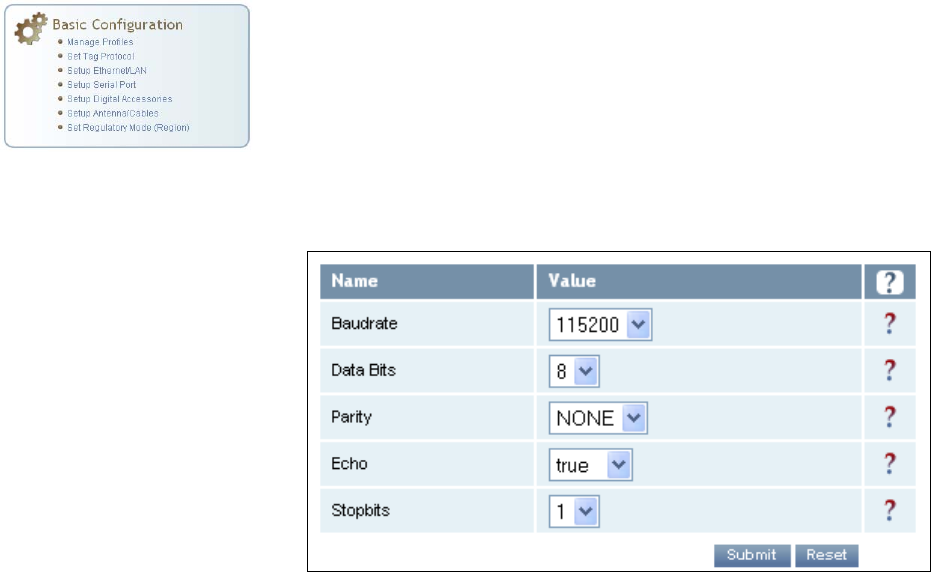
Setup Serial Port
The Setup Serial Port function allows you to configure the serial port
parameters. These parameters include:
h Baud rate
h Data bits
h Parity
h Echo
h Stop bits
Use the pull-down menus to select a value and press
Submit
to update the
reader.
1 2 3 4 5
6
7 8 9
Reader Configuration Tool
40
IDentity 5200 User Guide
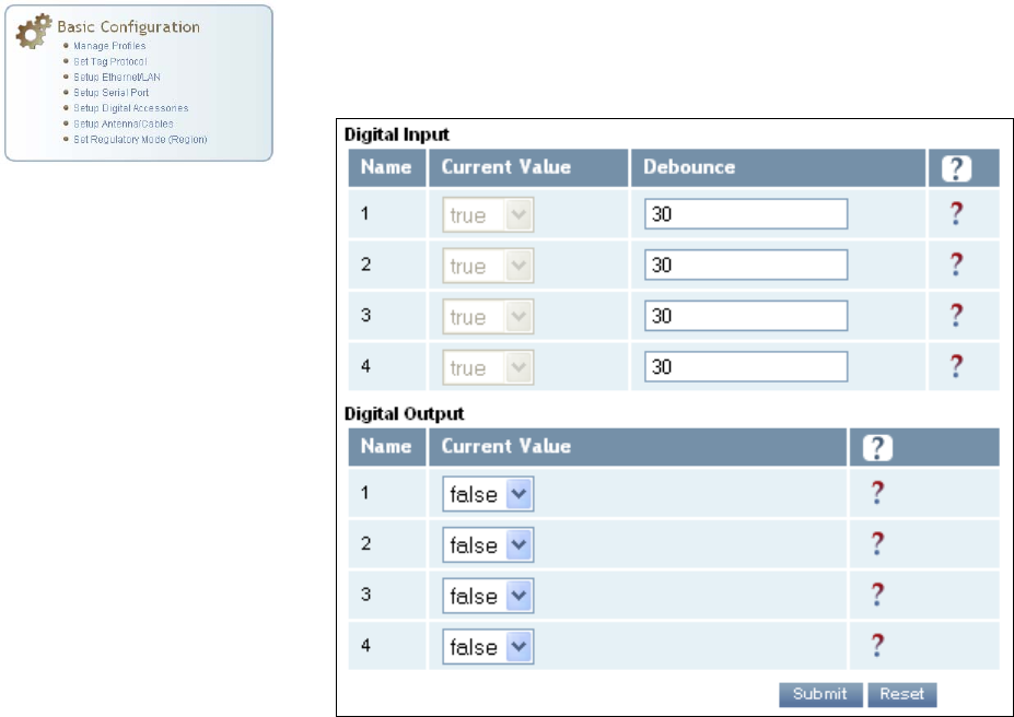
Setup Digital Accessories
The Setup Digital Accessories function allows you to configure the Digital
Inputs and Outputs on the reader.
Digital Input
The status of the four digital input values (1–4) can be seen in this window.
The
Current Value
is not configurable and is shown as
true
or
false
. The
Debounce value can be set and is in milliseconds.
Digital Output
The output value for each digital output can be set to true or false. Press
the
Submit
button to send the appropriate commands to the reader to
update the digital inputs and outputs.
Refer to the IDentity 5200 Protocol Reference Guide for more information
on configuring the digital inputs and outputs.
1 2 3 4 5
6
7 8 9
Reader Configuration Tool
IDentity 5200 User Guide
41
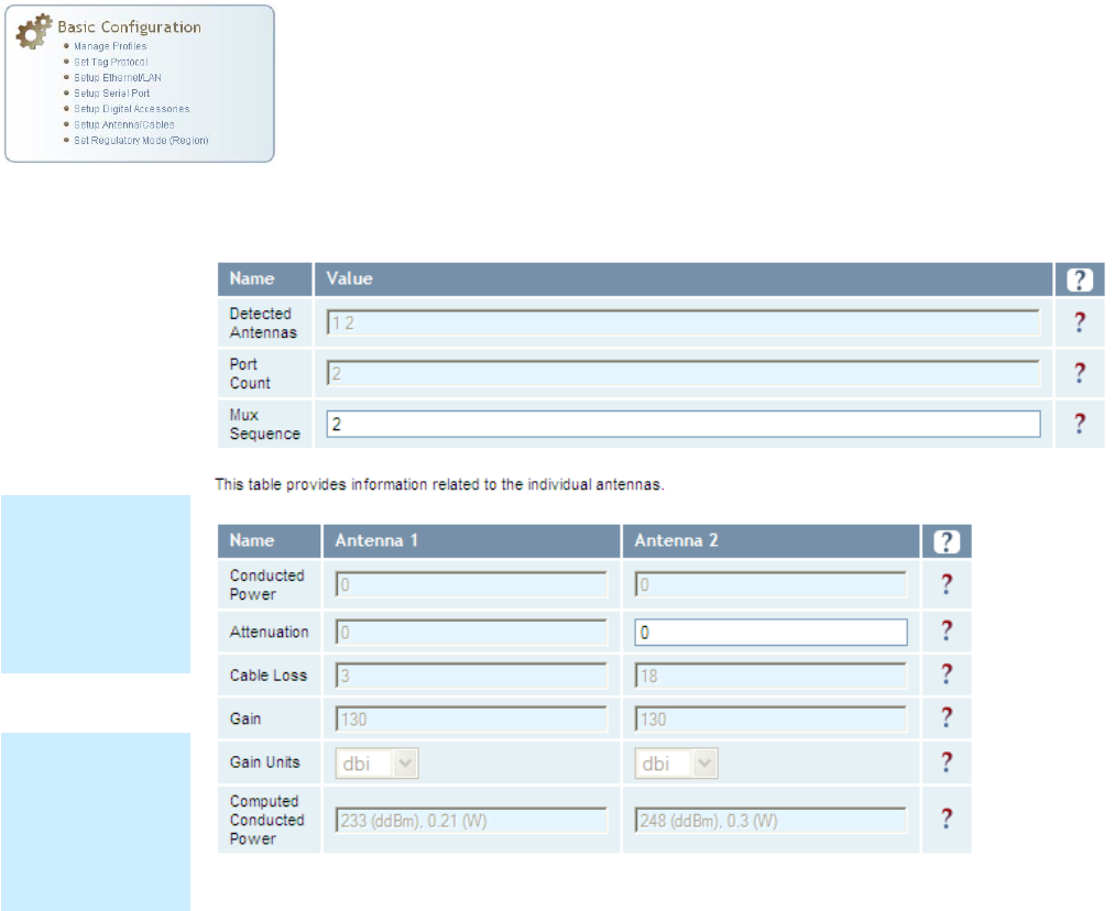
Setup Antenna/Cables
This page allows you to configure the properties of the reader’s antenna
configuration. For detailed description of each of the antenna and cable
variables, refer to Antenna Configuration in Chapter 4 – Reader Behavior of
the IDentity 5200 Protocol Reference Guide.
Enter the appropriate values for each antenna parameter and press the
Submit
button to update the antenna and cable configuration.
Antenna Setup
The reader is
configured at the
factory to operate
with specific
antennas.
Antenna Gain
Antenna gain may
differ, depending
on the specific
regulatory region.
1 2 3 4 5
6
7 8 9
Reader Configuration Tool
42
IDentity 5200 User Guide
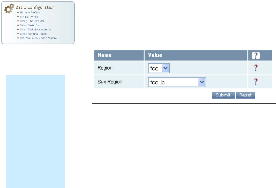
Set Regulatory Mode (Region)
This page allows the user to configure the reader to meet the regulatory
requirements for the geographic region where the reader is deployed. The
sub-region sets the secondary regulatory mode for the geographic region
where the reader is deployed.
For detailed information on each of these parameters, refer to the
IDentity 5200 Protocol Reference Guide. Descriptions are provided in the
setup.region and setup.sub_region configuration variable
sections.
Region Selection
The reader is
configured at the
factory to operate
within a specific
regulatory region. As
a result your region
selections may be
different from those
shown in this
manual.
Note that Region
Selection is not user
configurable.
1 2 3 4 5
6
7 8 9
Reader Configuration Tool
IDentity 5200 User Guide
43
Advanced Functions
With the Advanced Functions you can perform the following:
h Firmware Management
h Import/Export Configuration
h Command Line operations
h Expert Configuration
h User Application Management
h Change Operating Mode
h Restart
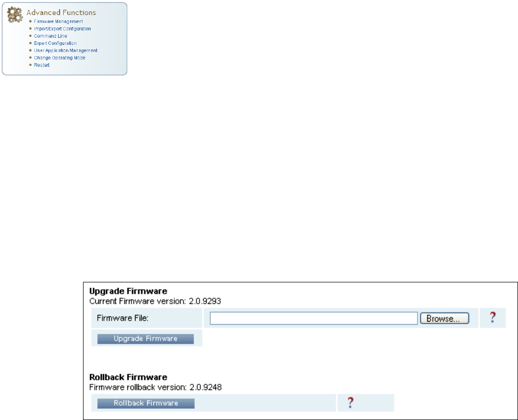
Firmware Management
This page allows you to read the current firmware version, upgrade the
reader firmware files, or rollback to the previous firmware version. Enter
the name of the Sirit provided firmware file in the
Firmware File
field. Use
the
Browse
button to help locate the file.
The
Rollback Firmware
button will roll back the firmware to the previous
version.
1 2 3 4 5
6
7 8 9
Reader Configuration Tool
44
IDentity 5200 User Guide
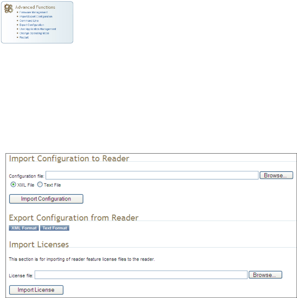
Import/Export Configuration
This page allows you to transfer a reader configuration to or from your host
computer. This is useful for configuring a reader to a known state.
Import Configuration to Reader
Enter the name of a saved configuration file in the
Configuration file
field.
Select the
XML File
option and press the
Transfer Configuration to Reader
button to send the profile to the reader.
Export Configuration from Reader
This function is used to export the current reader settings for later
uploading. Press the
XML Format
button to view the XML file in the browser.
Save this file to your computer if you wish retain it for future.
If you wish to view the current configuration parameters for a reader, press
Text Format
button.
Import Licenses
This function is used to import a reader feature license. Browse to the
license file and press
Import License
.
1 2 3 4 5
6
7 8 9
Reader Configuration Tool
IDentity 5200 User Guide
45
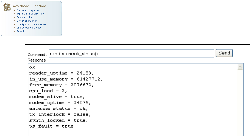
Command Line
This page allows you to directly enter reader commands from your web
browser.To directly enter commands from the Command Line Interface
(CLI), refer to the IDentity 5200 Protocol Reference Guide.
1 2 3 4 5
6
7 8 9
Reader Configuration Tool
46
IDentity 5200 User Guide
Expert Configuration
The Expert Configuration functions allow you to configure low-level functions
within the reader. These functions should only be accessed by expert users.
Expert configurations include:
h Setup
h Tag
h Version
h Information
h Communication
h Antennas
h Digital I/O
h Modem
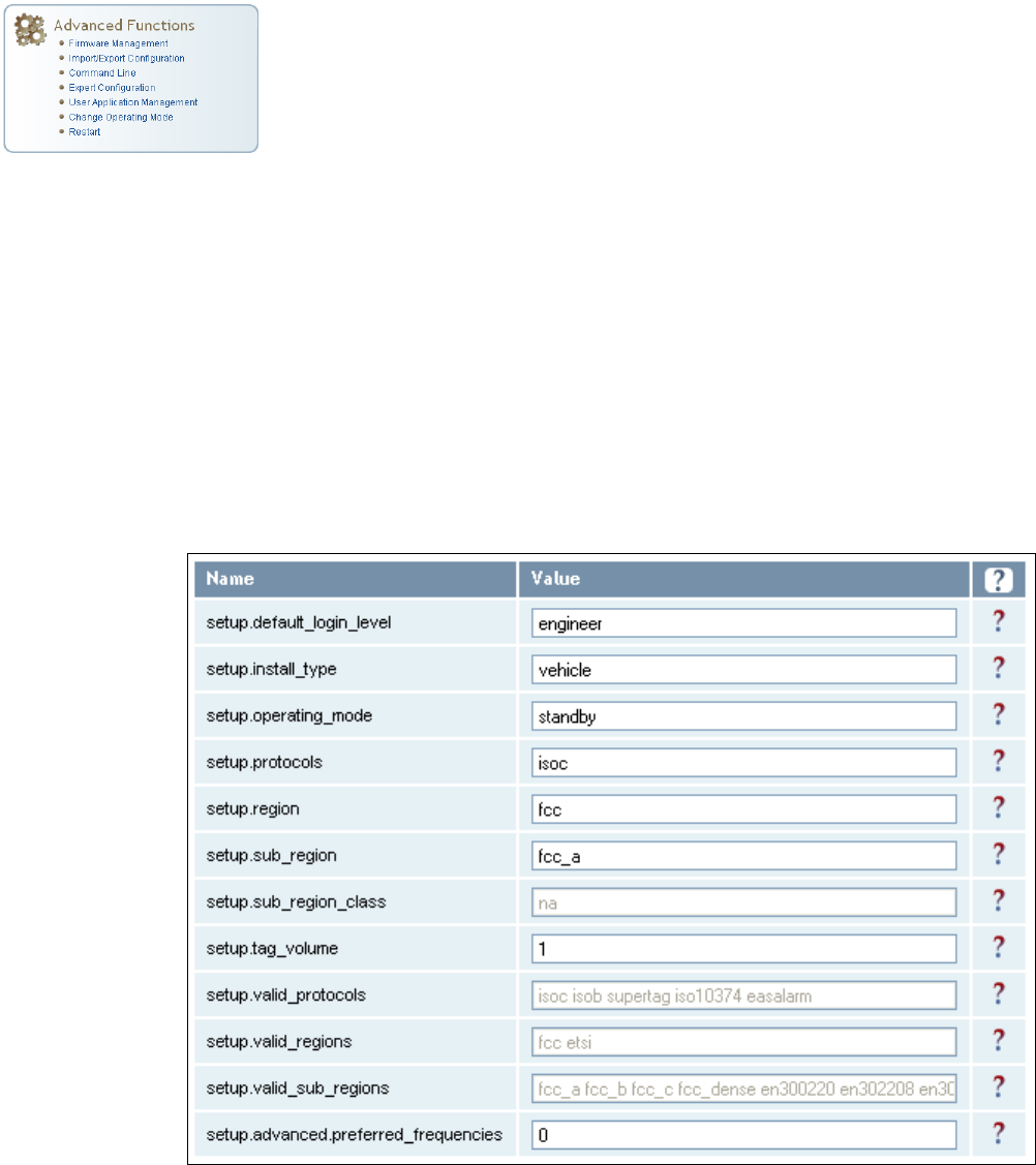
Expert Configuration – Setup
This page allows you to set the basic operating parameters of the reader
including region, sub region, mode, and active protocols. You can also view
the valid protocols and regions.
1 2 3 4 5
6
7 8 9
Reader Configuration Tool
IDentity 5200 User Guide
47
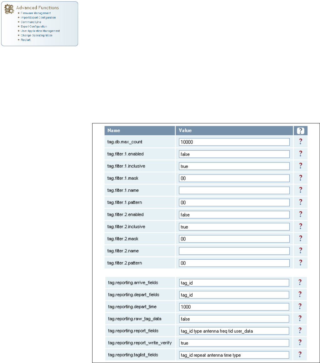
Expert Configuration – Tag
This page allows you to configure how the reader reports tags.
The IDentity 5200 supports the ability to filter tags. Filtering tags means to
eliminate tags from being reported based on the conditions specified in the
filter configuration variables. The reader supports eight filters and each
filter is specified by the following configuration variables:
h
enabled
– Enables or disables the filter.
h
inclusive
– Indicates to either include tags that match (Inclusive) or
include tags that do not match (Exclusive) the tag filter.
h
mask
– Mask (as an array of hex bytes) for the tag filter.
h
name
– Name given to the tag filter
h
pattern
– Pattern (as an array of hex bytes) for the tag filter
The following figure shows only a small sample of the available tag
configuration variables.
1 2 3 4 5
6
7 8 9
Reader Configuration Tool
48
IDentity 5200 User Guide
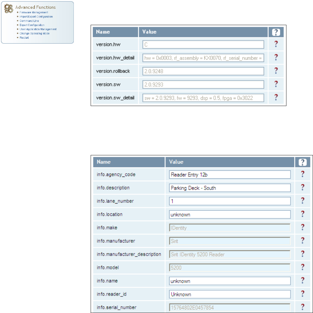
Expert Configuration – Version
This page displays the version of reader hardware and reader software
within the reader. The version numbers are read-only and will be needed if
you contact Sirit for technical support.
Expert Configuration – Information
This page allows you to customize the reader’s identity. You can assign
each reader a name, description, location, and zone. You can also set how
the reader reports timestamps.
1 2 3 4 5
6
7 8 9
Reader Configuration Tool
IDentity 5200 User Guide
49
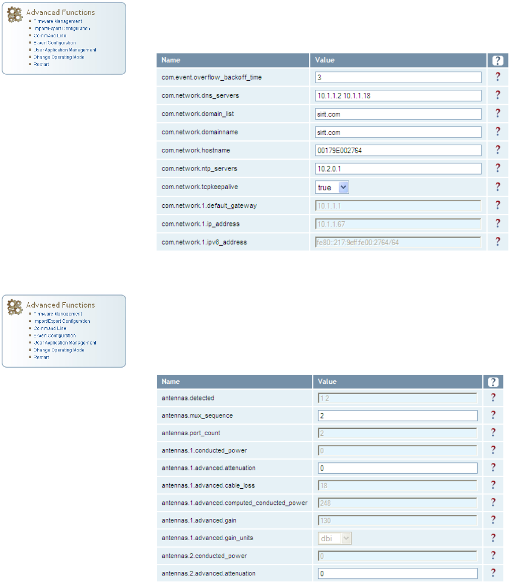
Expert Configuration – Communication
This page allows you to customize the reader’s communication parameters.
Refer to the Setup Ethernet/LAN and Setup Serial Port sections for
additional information.
Expert Configuration – Antennas
This page allows you to configure the properties of the reader’s antenna
configuration. For detailed description of each of the antenna and cable
variables, refer to the Antenna Configuration section in Chapter 4 – Reader
Behavior of the IDentity 5200 Protocol Reference Guide.
1 2 3 4 5
6
7 8 9
Reader Configuration Tool
50
IDentity 5200 User Guide
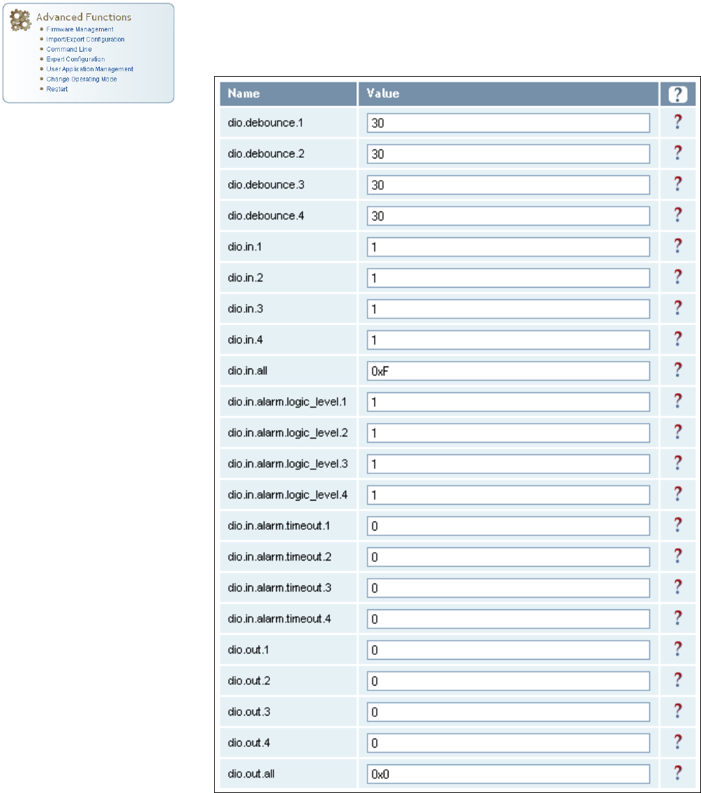
Expert Configuration – Digital I/O
This page allows you to configure the digital inputs and output behavior. You
can set the digital input debounce time (in milliseconds), as well as the
input and output pin values. Refer to the IDentity 5200 Protocol Reference
Guide for detailed information on each of these variables.
1 2 3 4 5
6
7 8 9
Reader Configuration Tool
IDentity 5200 User Guide
51
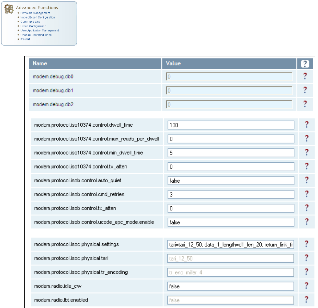
Expert Configuration – Modem
This page allows you to set the reader’s modem control variables. These
variables control functions such as EPC link, modulation depth, return link
frequency, and others. Refer to the IDentity 5200 Protocol Reference Guide
for detailed information on each of these variables.
The following figure shows only a small sample of the available modem
configuration variables.
1 2 3 4 5
6
7 8 9
Reader Configuration Tool
52
IDentity 5200 User Guide
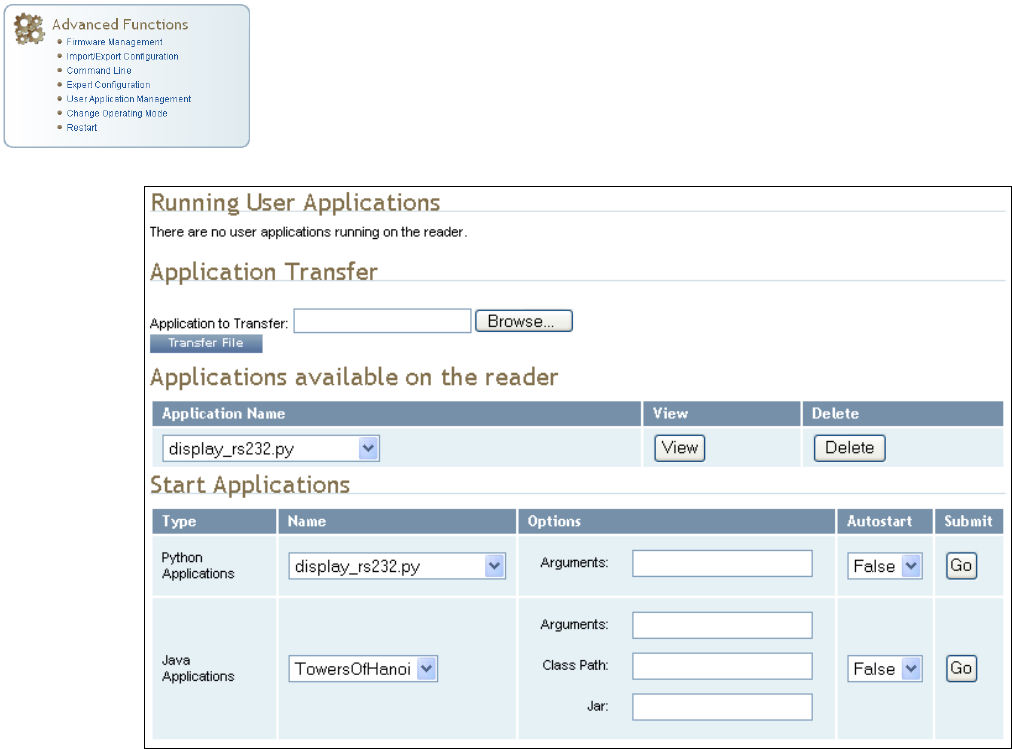
User Application Management
This page lists any user applications currently available on the reader and if
any applications are running. This page also allows you to upload scripts to
the reader.
h
Running User Applications – Lists any user applications currently
running on the reader. The application name, process ID, configuration,
and status are provided. Controls are provided to view the application
file and stop the application.
h
Application Transfer – This function allows you to load custom user
applications onto the reader.
h
Applications available on the reader – This function allows you to view a
list of all user applications stored on the reader. Controls are provided
to view the application and delete it from the reader.
h
Start Applications – This function allows you to start Python and Java
applications.

1 2 3 4 5
6
7 8 9
Reader Configuration Tool
IDentity 5200 User Guide
53
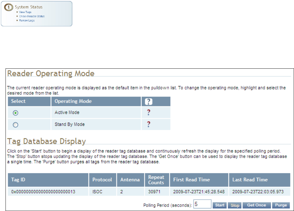
Change Operating Mode
This page allows you to configure the operational mode of the reader.
The reader supports the following operational modes:
h
Active Mode - Reader is continuously attempting to singulate tags and
automatically reports any singulated tag via an asynchronous event
notification on the event channel.
h
Stand By Mode - Reader is not transmitting any energy, unless
processing a tag related command. The RF transmitter is enabled at the
beginning of the command processing, any protocol operations required
for the command are performed, and then the RF transmitter is turned
back off.
1 2 3 4 5
6
7 8 9
Reader Configuration Tool
54
IDentity 5200 User Guide
View Tags
All tags read by the reader are stored in a database on the reader. This
page allows you to view the tags in the database as well as change the
current Operating Mode (Active or Stand By).
Press Start to begin displaying the tag database. This page is automatically
refreshed every five seconds. Press Get Once to update the database one
time (refresh is off). Press Purge to purge all tags from the database.
1 2 3 4 5
6
7 8 9
Reader Configuration Tool
IDentity 5200 User Guide
55
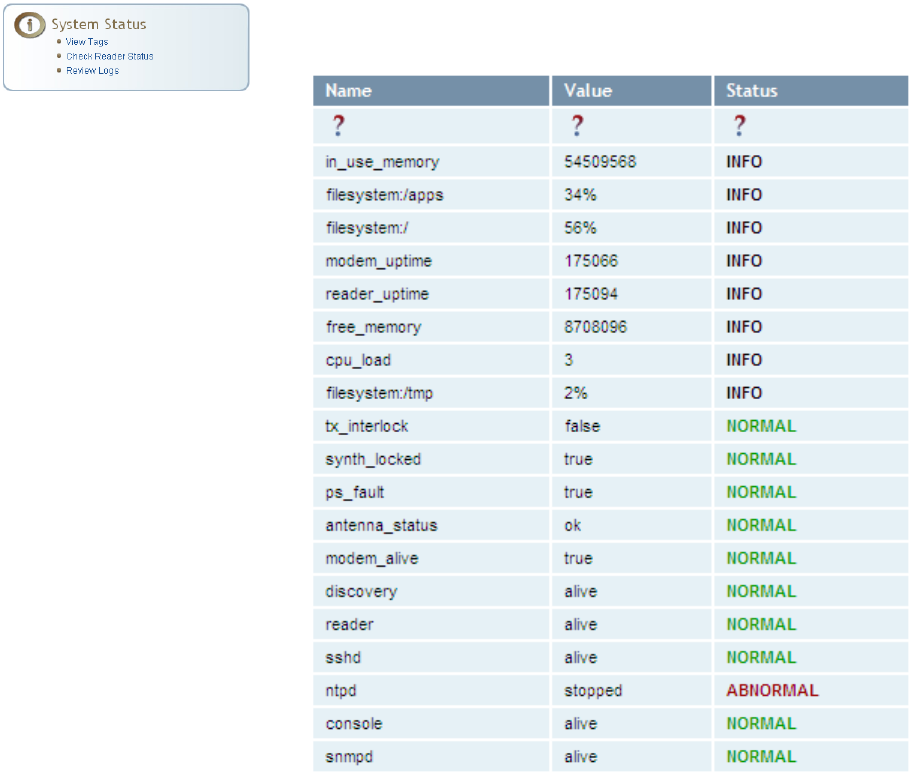
Check Reader Status
This page allows you to view the reader status. This information can be
used by Sirit Technical Support to verify reader operation.
1 2 3 4 5
6
7 8 9
Reader Configuration Tool
56
IDentity 5200 User Guide
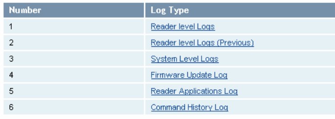
Review Logs
This page allows you to view the reader logs. These logs can be used by Sirit
Technical Support to verify reader operation. The reader logs include:
h
Reader level Logs
– System level reader operation
h
System Level Logs
– Linux logs
h
Firmware Update Log
– System level
h
Reader Applications Log
– User application logs
h
Command History Log
– Recent commands sent to the reader.

1 2 3 4 5 6
7
8 9
Configuring Digital I/O
IDentity 5200 User Guide
57
Configuring Digital Inputs and Outputs
Digital input and output signals are provided via the bulkhead connector.
Refer to Chapter 8 – Specifications for the connector pin out. Refer to
Figure 5 for in this chapter for an example input/output circuit.
This chapter describes how to configure the digital inputs and outputs.
Digital Inputs
The digital inputs (DIN1 – DIN4) can be used as general purpose inputs or
to trigger the reader for tag reading. Unused or open digital inputs are
floating inside the reader.
To activate the input, pull it low (0 Vdc) with an external device or
connection to ground that can sink 2.5 mA. No voltage higher than +24 Vdc
or lower than 0 Vdc should ever be connected to the input. See Figure 5 for
an example of a typical motion sensor installed as a tag read trigger device.
Digital Outputs
The digital outputs (DOUT1 – DOUT4) can be used as general purpose
outputs, to indicate tag reading activity, or to indicate the reader is
transmitting (RF On). Digital outputs can be pulled high.
No voltage higher than +40 Vdc or lower than 0 Vdc should ever be
connected to a digital output. The reader activates the output by pulling it
low (0 Vdc) and can sink current such that power dissipation is ≤ 1W.
Digital I/O Monitoring and Control Scripts
Several digital I/O monitoring and control scripts are provided with the
reader to allow you to monitor the digital I/Os and take specific actions.
These Python application scripts can be used as is or modified to suit your
particular application. For detailed information on loading Python scripts,
refer to Chapter 5 – Embedded Reader Applications of the IDentity 5200
Protocol Reference Guide.
1 2 3 4 5 6
7
8 9
Configuring Digital I/O
58
IDentity 5200 User Guide
scan_trigger.py
This routine monitors the state of the digital input pin specified as the input
parameter. If the state of the pin is low, the operating mode is set to standby. If
the I/O pin state changes to high, the operating mode is set to polled.
Inputs: <pin> – (optional) Input pin number (1–4). Default is digital in 1.
<trigger logic level> –(optional) 0 or 1. Default is trigger on 1.
Examples:
scan_trigger.py Monitors digital input pin 1
scan_trigger.py 1 Monitors digital input pin 1
scan_trigger.py 4 Monitors digital input pin 4
scan_trigger.py 3 0 Monitors digital input pin 3, trigger on 0
scan_trigger_timer.py
This routine monitors the I/O pin. When the pen goes high, the timer is started
and the operating mode is set to polled. While the timer is running, I/O pin state
changes are ignored. When the timer expires, the operating mode is set to
standby. The minimum value for the timer is 10 milliseconds (ms).
Inputs: <pin> – (optional) Output pin number (1–4). Default is output 1.
<time> – (optional) Time, in ms for timer to run. Default is 1000 ms.
<trigger logic level> –(optional) 0 or 1. Default is trigger on 1.
Examples:
scan_trigger_timer.py Monitors input 1, timer 1000 ms,
trigger on 1
scan_trigger_timer.py 2 Monitors input 2, timer 1000 ms,
trigger on 1
scan_trigger_timer.py 4 2000 Monitors input 4, timer 2000 ms,
trigger on 1
scan_trigger_timer.py 3 4000 0 Monitors digital input 3, timer 4000 ms,
trigger on 0
1 2 3 4 5 6
7
8 9
Configuring Digital I/O
IDentity 5200 User Guide
59
signal_read.py
This routine will activate a digital output if a tag is successfully read. The
optional output pin number can be specified on the command line. If not
specified, output pin 1 is selected and a default value of 1000 milliseconds is
used. The output will remain high for n ms, where n is either the default of 1000
ms, or the value supplied on the command line. Minimum value for n is 10 ms.
Inputs: <pin> – (optional) Output pin number (1–4). Default is output 1.
<time> – (optional) Time, in ms, to keep the output high. Default is
1000 ms (1 sec).
<logic level> – (optional) Logic level for digital out On. 0 or 1. Default
is 1 (On).
Examples:
signal_read.py Turns on output 1 for 1000 ms on tag reads
signal_read.py 2 Turns on output 2 for 1000 ms on tag reads
signal_read.py 1 5000 Turns on output 1 for 5000 ms on tag reads
signal_read.py 1 500 Turns on output 1 for 500 ms on tag reads
signal_read.py 1 800 0 Turns on digital output 1,logic level 0, for
800 ms on tag reads
1 2 3 4 5 6
7
8 9
Configuring Digital I/O
60
IDentity 5200 User Guide
signal_read_crc_error.py
This routine will turn on a digital output if a tag read CRC error is detected. The
output pin number can be specified on the command line. If not specified,
output pin 1 is used. The output pin will remain high for n ms, where n is either
the default of 1000 ms or the value supplied on the command line. Minimum
value for n is 10 ms.
Inputs: <pin> – (optional) Output pin number (1–4). Default is output 1.
<time> – (optional) Time, in ms, to keep the output high. Default is
1000 ms.
<logic level> – (optional) Logic level for digital out On. 0 or 1.
Default is 1 (On).
Examples:
signal_read_crc_error.py
Turns on output 1, logic level 1 for on
for 1000 ms on tag read CRC error.
signal_read_crc_error.py 2
Turns on output 2, logic level 1 for on
for 1000 ms on tag read CRC error.
signal_read_crc_error.py 1 5000
Turns on output 1, logic level 1 for
on for 5000 ms on tag read CRC
error.
signal_read_crc_error.py 1 500
Turns on output 1, logic level 1 for
on for 500 ms on tag read CRC
error.
signal_read_crc_error.py 1 800 0
Turns on output 1, logic level 0 for
on, for 800 ms on tag CRC error.
rf_mon.py
This routine will monitor the state of the transmitter. If the transmitter is on, it
sets the appropriate output pin high. If low, it sets the output pin low.
Inputs: <pin> – (optional) Output pin number (1–4). Default is output 1.
<logic level> – (optional) Logic level for digital out On. 0 or 1.
Default is 1 (On).
Examples:
rf_mon.py Monitors RF status, set/clear output 1 on change, logic
level 1 for on
rf_mon.py 1 Monitors RF status, set/clear output 1 on change, logic
level 1 for on
rf_mon.py 2 Monitors RF status, set/clear output 2 on change, logic
level 1 for on
rf_mon.py 3 0 Monitors RF status, set/clear output 3 on change, logic
level 0 for on
1 2 3 4 5 6
7
8 9
Configuring Digital I/O
IDentity 5200 User Guide
61
Digital Input Alarm Generation
The IDentity 5200 can be configured to generate an alarm when a digital
input is disconnected or sensor failure is detected. The alarm is triggered
when the signal level on the digital input stays in the specified state longer
than the specified alarm timeout. This behavior can be configured
independently for each digital input.
The configuration variable
dio.in.alarm.logic_level.<N>
(where <N> is
1,2,3,4) sets whether the alarm is coupled to a input logic level of 0 (low) or
1 (high).
The configuration variable
dio.in.alarm.timeout.<N>
(where <N> is 1,2,3,4)
sets the amount of time, in seconds, to wait for a signal state change. A
value of 0 (default) disables alarm generation.
The digital input logic level is used along with the corresponding digital input
pin timeout value to determine if an alarm (in the form of an event) should
be generated. If a timeout value is set, the input pin is monitored. If the
input pin value does not change during the timeout period AND the input
pin value matches the alarm logic level, the event
event.dio.in.alarm.timeout.n
(where n is the pin number) is generated. This
alarm event generation can be helpful in alerting to the loss of digital inputs
to the reader.
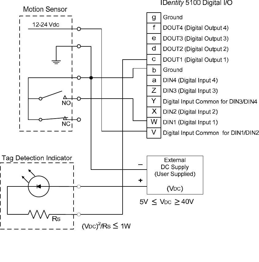
1 2 3 4 5 6
7
8 9
Configuring Digital I/O
62
IDentity 5200 User Guide
Digital I/O Hardware Connection
Figure 5 shows a typical sensor/indicator connection to the digital I/Os.
Figure 5
Example Motion Detector and Indicator connected to the Digital I/O

1 2 3 4 5 6 7
8
9
Specifications
IDentity 5200 User Guide
63
Specifications
Reader Specifications (General)
Frequency Range 860–960 MHz (Factory configured for specific region)
Connectors RS-232, Digital I/O, Ethernet LAN
Input Voltage 12 to 24 Vdc, 60 W
Input Current 2.5 A maximum at 24 Vdc
5.0 A maximum at 12 Vdc
Reader Specifications (FCC)
Dimensions 16.5 x 12.2 x 3.4 in (419 x 310 x 86 mm)
Weight 11.0 lbs (5 kg)
Frequency Range
FCC Part 90
Dense
911.25 911.75 912.25
912.75 913.25 913.75
914.25 914.75 915.25
915.75 916.25 916.75
917.25 917.75 918.25
918.75 919.25 919.75
920.25
FCC Part 90
Low Band
(All protocols
except T21)
902.750
903.250
RF Power 10 mW – 2 W conducted (10 – 33 dBm)
Power
Consumption
13 W (typical while idle)
34 W (typical at 1W conducted output power)
40 W (maximum at 1W conducted output power)

1 2 3 4 5 6 7
8
9
Specifications
64
IDentity 5200 User Guide
Figure 6
Typical Power Consumption versus Conducted Output Power at 910 MHz
Environmental Specifications
Operating Temperature -40 °F to 131 °F (-40 °C to 55 °C)
Storage Temperature -40 °F to 185 °F (-40 °C to 85 °C)
Maximum Shock 1 foot (0.3 meter) drop to any corner
Relative Humidity 100%, condensing
International Protection
Rating
IP65
Power Supply Specifications
Model Lambda DSP100-24
Input Voltage 90 – 264 Vac,
Input Frequency 47 to 63 Hz
Power 100.8 W
Holdup Time 10 ms (115 Vac)
Output Voltage 24 VDC
Output Current 4.2 A

1 2 3 4 5 6 7
8
9
Specifications
IDentity 5200 User Guide
65
RS-232 Specifications
Connector DB-9S
Baud rate 1200 - 115200 (Default = 115200)
Parity None
Data bits 8
Stop bits 1
Signals Pin 1 - NC
Pin 2 - TXD
Pin 3 - RXD
Pin 4 - Connected to Pin 6
Pin 5 - GND
Pin 6 - Connected to Pin 4
Pin 7 - CTS
Pin 8 - RTSA
Pin 9 - NC
Ethernet LAN Specifications
Connector RJ-45
Ethernet 10/100 BaseT
Indicators Yellow - Indicates link is operational
Green - Indicates network traffic detected.
Signals Pin 1 – TXD+ (Transmit Data +)
Pin 2 – TXD- (Transmit Data -)
Pin 3 – RXD+ (Receive Data +)
Pin 4 – NC
Pin 5 – NC
Pin 6 – RXD- (Receive Data -)
Pin 7 – NC
Pin 8 – NC
Antenna Cable Specifications
Manufacturer Time Microwave Systems
Part No. LMR-400 (replacement for RG-8/9913)
Connector Type RP-TNC
Impedance 50 ohms
Attenuation 3.9 dB/100 ft (12.8 dB/100m)
1 2 3 4 5 6 7
8
9
Specifications
66
IDentity 5200 User Guide
External Antenna Specifications (FCC)
Part No. ANTENNA–013 ANTENNA–003
Type PATCH PATCH
Frequency (FCC) 902 – 928 MHz 902 – 928 MHz
Polarization Linear (Horizontal) Linear (Horizontal)
Gain 13 dBi 15 dBi
VSWR, maximum 1.7:1 or less 1.8:1 or less
Input impedance 50 ohm (nominal) 50 ohm (nominal)
Input Power 6 W (maximum) 4 W (maximum)
Reader Power into
Antenna
2 W (maximum) 1.5 W (maximum)
Size 17.1 x 17.7 x 1.4 in
(450 x 450 x 36 mm)
42 x 36 x 5 in
(1143 x 914 x 127 mm)
Weight 6.6 lbs (3 kg) 80 lbs (36.4 kg)
Site License –
Customer Disclaimer
Customer (end user) acknowledges that a site license is required for each reader
system location. It is the customer’s responsibility to file for the site license and
submit the appropriate filing payment. Sirit can assist with the completion of
forms. United States filings require completion and submission of FCC Form 601
with Schedule D and H. Canadian filings require completion and submission of
Industry Canada Forms IC2365BB and IC2430BB.
Caution:
This equipment complies with FCC Part 90 and Industry Canada.RSS-137 rules.
Any changes or modifications not expressly approved by Sirit could void the user’s
authority to operate the equipment.
The professional installer will need to calculate and verify the reader’s power
output allowable based on the antenna (gain) used and cabling (loss) effects.
This value will be used in the user’s submission of their site license application.
The maximum antenna gain plus cable effects for a given output power can be
calculated by:
44.8 dBm (ERP) - Pout
where Pout is the measured RF output power (dBm)
Reader output power is limited to a maximum of 2W under all conditions. When
operating at that power level, the maximum permissible antenna gain is 11.2dBd.
WARNING:
FCC Radiation Exposure Statement. The antennas used for this transmitter
must be installed to provide a separation distance of at least 1 meter from all
persons and must not be co-located or operating in conjunction with any other
antenna or transmitter.

1 2 3 4 5 6 7
8
9
Specifications
IDentity 5200 User Guide
67
Bulkhead Connector/Interface Cable Pinout
Pair Pin Color Pin Name Function
A Black Tx+ Ethernet 1
B Green Tx- Ethernet
C Black Rx+ Ethernet 2
D Orange Rx- Ethernet
E Blue VC2+ Ethernet 3
F Black VC2- Ethernet
G Black VC2+ Ethernet 4
H Brown VC2- Ethernet
J Black RS-232 TXD Serial Port 5
K Red RS-232 RXD Serial Port
L Black 6
M White RS-232 GND Serial Port
N Black 7
P Yellow RS-232 CTS Serial Port
R Red RS-232 RTS Serial Port 8
S White No Connect
T Red +24 Vdc Power 9
U Green 24 Vdc GND Ground
V Red DIN Ref 1 Digital Input Common 10
W Blue DIN1 Digital Input 1
X Red DIN2 Digital Input 2 11
Y Yellow DIN Ref 2 Digital Input Common
Z Red DIN3 Digital Input 3
12
a Brown DIN4 Digital Input 4
b Red GND Ground (Reader) 13
c Orange DOUT1 Digital Output 1
d Green DOUT2
Digital Output 2
14
e White DOUT3
Digital Output 3
f Green DOUT4
Digital Output 4
15
g Blue GND Ground (Reader)
h n/a n/a n/a 16
j n/a n/a n/a

1 2 3 4 5 6 7
8
9
Specifications
68
IDentity 5200 User Guide
Battery Specifications (Optional)
Battery Lithium/Manganese Dioxide
Designation ANSI/NEDA 5012LC / IEC-CR1220
Voltage 3.0 V
Average capacity 40 mAh to a terminal voltage of 2 V
1 2 3 4 5 6 7 8
9
Safety Instructions
IDentity 5200 User Guide
69
Safety Instructions
Power Disconnect Device
The plug on the power supply cord is intended to be the power disconnect
device. As a result, the power source (socket or outlet) shall be located near
the equipment and shall be easily accessible.
RF Safety
WARNING:
FCC Radiation Exposure Statement. The antennas used for this transmitter
must be installed to provide a separation distance of at least 1 meter from all
persons and must not be co-located or operating in conjunction with any other
antenna or transmitter.
Caution:
The IDentity 5200 UHF Reader is equipped with two (2) RF ports and is
factory configured to operate on the internal RF port (1). To prevent reader
damage, the external RF Port (2) must be properly terminated with a 50 ohm
load or a functional UHF antenna before power up if the reader has been
configured to use this port. Never power up the reader unless the appropriate
loads or antennas are connected. Always power down the reader before
removing an antenna or load from an RF port.
The maximum antenna cable length is 10 meters.
Electrostatic Discharge
ATTENTION
IDentity 5200 antenna ports may be susceptible to damage from static
discharge or other high voltage. Use proper Electrostatic Discharge
(ESD) precautions to avoid static discharge when handling or making
connections to the IDentity 5200 reader antenna or communication
ports. Equipment failure can result if the antenna or communication
ports are subjected to ESD.
Regulatory Compliance
Caution:
The IDentity 5200 is designed to meet the regulatory requirements in those
jurisdictions in which it is offered. Changes or modifications not expressly
approved by Sirit Technologies for compliance could void the user's authority
to operate the equipment.
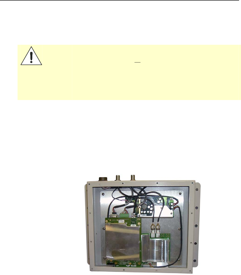
Appendix A Disposal of the IDentity 5200 Reader
70
IDentity 5200 User Guide
Disposal of the ID
entity
5200 Reader
Prior to disposing of the IDentity 5200 Reader, the battery must be
removed. The battery used in the IDentity 5200 is a Lithium / Manganese
Dioxide (Li/MnO2) type. This battery contains no measurable amounts of
mercury, lead, or cadmium.
Caution:
The procedure outlined in this appendix requires opening the IDentity 5200
Reader case in order to remove the battery prior to disposal. Opening the
case of the IDentity 5200 will void the warranty. In addition, opening the case
may adversely affect any future operation of the reader.
Never open the case of the IDentity 5200 Reader unless you are going to
remove the battery and dispose of the unit.
All disposal operations must be performed within local guidelines and laws. It
is the responsibility of the reader owner to ensure all local and regional laws
and regulations are followed for proper reader disposal.
To remove the battery, perform the following:
1 Remove the reader from service and disconnect any power, antenna,
and communication cables.
2 Remove the 12 Philips head screws on the front panel and remove the
panel.
3 If necessary, disconnect the LED wires.
4 Using an SMA connector wrench, remove the cable from the antenna
and set the antenna aside.
Appendix A Disposal of the IDentity 5200 Reader
IDentity 5200 User Guide
71
5 Remove the serial, digital I/O, and Ethernet cables from the digital
board.
6 Remove the nine screws securing the shield can to the digital board.
7 Remove the remaining screw securing the digital board to the chassis.
8 Remove the digital board from the enclosure and locate the battery
next to the LEDs.
9 Use a small flat-blade screwdriver to push the battery out of the holder.
10 Properly dispose of battery according to local and regional laws and
regulations.
11 Properly dispose of reader according to local and regional laws and
regulations.

Appendix B Reader Maintenance
72
IDentity 5200 User Guide
Reader Maintenance
Antenna Radome Maintenance
The Sirit IDentity 5200 UHF RFID reader is a low maintenance device.
However, the user must ensure that any reader antenna radomes are kept
clean. Any build-up of foreign substances, water, or snow will degrade the
performance of the unit
IDentity 5200 User Guide

IDentity 5200 User Guide