3M Traffic Safety Systems ID6200 IDentity 6204 (900 MHz) RFID Reader User Manual
3M Traffic Safety Systems IDentity 6204 (900 MHz) RFID Reader
user manual

IDentity 6204
USER’s GUIDE
V1.02
January 26, 2012
© 2012 Sirit Inc., All Rights Reserved. “Sirit”, the Sirit Design, “RFID by Sirit”, the RFID by Sirit Design and “vision beyond sight” are all
trademarks of Sirit Inc. All other trademarks are the property of their respective owners. Specifications are subject to change without notice.
This product is covered by one or more of the following patents: U.S. Patent No. 7,199,713, 7,209,040, 6,346,881, and 6,617,962.
Disclaimer and Limitation of Liability
The content of this manual is for information use only and is subject to change without notice. Sirit assumes no responsibility or liability for
any errors or inaccuracies that may appear in this publication. No part of this manual may be reproduced in any form or by any means,
electronic, mechanical, recording, or otherwise, without the prior written permission of Sirit.
Sirit products are not designed, intended, authorized or warranted to be suitable for life support applications or any other life critical
applications which could involve potential risk of death, personal injury, property damage, or environmental damage.
FCC Notice
This equipment has been tested and found to comply with the limits for a Class B digital device, pursuant to Part 15 of the FCC Rules.
These limits are designed to provide reasonable protection against harmful interference in a residential installation. This equipment
generates, uses, and can radiate radio frequency energy and, if not installed and used in accordance with the instructions, may cause
harmful interference to radio communications. However, there is no guarantee that interference will not occur in a particular installation. If
this equipment does cause harmful interference to radio or television reception, which can be determined by turning the equipment off and
on, the user is encouraged to try to correct the interference by one or more of the following measures:
• Reorient or relocate the receiving antenna.
• Increase the separation between the equipment and receiver.
• Connect the equipment into an outlet on a circuit different from that to which the receiver is connected.
• Consult FSTech-Sirit or an experienced radio/TV technician for help.
Le présent appareil est conforme aux CNR d'Industrie Canada applicables aux appareils radio exempts de licence. L'exploitation est
autorisée aux deux conditions suivantes : (1) l'appareil ne doit pas produire de brouillage, et (2) l'utilisateur de l'appareil doit accepter tout
brouillage radioélectrique subi, même si le brouillage est susceptible d'en compromettre le fonctionnement.
This Class B digital apparatus complies with Canadian ICES-003.
Cet appareil numérique de la classe B est conforme à la norme NMB-003 du Canada.
About Sirit, a Federal Signal Technologies Company
Sirit, a Federal Signals Technologies Company, designs, develops, manufactures and sells Radio Frequency Identification (RFID)
technology. Targeted at a diverse set of markets RFID technology has become a core technology for applications including: electronic toll
collection, access control, cashless payment systems, product identification, and supply chain management systems including logistics,
warehousing and manufacturing, and asset management.
Federal Signal Technologies
2 Technology
Irvine, CA 92618
Tel: (949) 341-0409
Fax (949) 341-0521
Web: www.fstech.com
Sirit
1321 Valwood Parkway, Suite 620
Carrollton, Texas 75006 United States
Tel: 972.243.7208
Fax: 972.243.8034
Toll Free: 1.866.338.9586
Web: www.sirit.com

Preface
IDentity 6204 User’s Guide i
Preface
Intended audience
This document is intended for those who wish to setup and operate the
IDentity 6204 Radio Frequency Identification system. Before attempting to
install, configure, and operate this product, you should be familiar with the
following:
h Windows-based software installation and operation
h Device communication parameters including Ethernet and serial
communications
h RFID reader configuration including antenna placement
h Basic digital input/output control
What’s in this guide
The information in this guide is presented as follows:
Chapter 1 - Reader Overview:This chapter provides a brief overview of the IDentity
6204 hardware and software.
Chapter 2 - Reader Equipment Installation – This chapter describes how to
mechanically and electrically install the reader.
Chapter 3 - Reader Startup Tool (RST) Software Installation – This chapter
describes how to install the Microsoft Windows RST application.
Chapter 4 - Reader Operation – This chapter describes how to initially test a reader
and how to operate deployed readers.
Chapter 5 - Reader Startup Tool (RST) – This chapter describes the RST and the
various functions you can perform with this Microsoft Windows application.
Chapter 6 - Reader Configuration Tool (RCT) – This chapter describes the RCT and
the various functions you can perform with this embedded reader application.
Chapter 7 - Configuring Digital Inputs and Outputs – This chapter describes how to
setup the reader’s digital inputs and outputs.
Chapter 8 - Specifications – This chapter detailed mechanical, electrical, and
environmental specifications for the IDentity 6204.
Chapter 9 - Safety Instructions – This chapter provides important safety information
about the IDentity 6204. All users must read this section before installing or
operating this reader.
Appendix A – Error Handling – This appendix lists IDentity 6204 errors and
warnings. Corrective actions are provided where applicable.

ii IDentity 6204 User’s Guide
What’s New in this Version
Version 1.0 of this User’s Guide is the first release.
Conventions used in this manual
The following conventions are used in this manual:
Bold courier font indicates code entered by the user
(values) within parentheses indicate parameters
(values) in italics indicate user defined variables.
<n> indicates a variable number used in a function that can apply to
several different devices such as antennas or I/O ports.
WARNING: Warnings advise the reader that a hazardous condition can be created by a
particular action that can cause bodily injury or extreme damage to equipment
ATTENTION This warning indicates that the device is susceptible to Electro Static
Discharge and appropriate precautions must be taken to avoid equipment
damage.
Caution: Cautions advise the reader that a condition can be created by a particular action
that can cause equipment damage or result in equipment operation that violates
regulatory requirements.
NOTES
Important information
and other tips are
presented in light
blue boxes to the left
of the applicable
section.

Contents
IDentity 6204 User’s Guide iii
Table of Contents
1 Reader Overview...................................................................................................................................1
1.1. Reader Hardware .................................................................................................................................1
1.2. Reader Software...................................................................................................................................2
2 Reader Equipment Installation..........................................................................................................3
2.1. Mechanical Installation.......................................................................................................................3
2.2. Electrical Installation...........................................................................................................................5
2.2.1. Connecting the Serial Port.........................................................................................................6
2.2.2. Connecting and Configuring the Ethernet Port.........................................................................6
2.2.3. Connecting the External Antenna .............................................................................................7
2.2.4. Connecting Digital Inputs/Outputs............................................................................................7
2.2.5. Connecting the Power ...............................................................................................................7
3 Reader Startup Tool (RST) Software Installation ............................................................................8
3.1. Installing RST Software.......................................................................................................................8
3.2. Windows 7 Setup..................................................................................................................................9
3.3. Reader Startup................................................................................................................................... 10
3.4. Initial Reader Setup.......................................................................................................................... 11
4 Reader Operation.............................................................................................................................. 15
4.1. Basic Operation with RST................................................................................................................. 15
4.2. Deployed Reader Operation with RCT............................................................................................ 17
5 Reader Startup Tool (RST) ............................................................................................................... 19
5.1. View Readers on the Network......................................................................................................... 19
5.2. Configure Reader with the Setup Wizard...................................................................................... 20
5.3. Customize Discovery Options.......................................................................................................... 21
5.4. View or Change the Reader’s Network Settings........................................................................... 22
5.5. Reader Test Tool (RTT)...................................................................................................................... 23
5.5.1. General Page ...........................................................................................................................23
5.5.2. Tag Performance Page ............................................................................................................27
5.5.3. Tag Management Page............................................................................................................29
5.5.4. Macros Page ............................................................................................................................30
5.5.5. Event Handling Page...............................................................................................................32
5.5.6. Antenna Settings Page.............................................................................................................33
Contents
iv IDentity 6204 User’s Guide
5.6. Reader Diagnostics Tool (RDT)........................................................................................................ 34
5.6.1. Channel Statistics....................................................................................................................34
5.6.2. Alarms.....................................................................................................................................35
5.6.3. Tag Report...............................................................................................................................36
5.6.4. Spectrum Analyzer..................................................................................................................37
5.6.5. Power Ramp Tool ...................................................................................................................38
6 Embedded Reader Configuration Tool (RCT)................................................................................ 39
6.1. Basic Configuration........................................................................................................................... 40
6.1.1. Configuration Page Header.....................................................................................................40
6.1.2. Manage Profiles ......................................................................................................................41
6.1.3. Set Tag Protocol......................................................................................................................43
6.1.4. Setup Ethernet/LAN................................................................................................................44
6.1.5. Setup Serial Port......................................................................................................................45
6.1.6. Setup Digital Accessories .......................................................................................................46
6.1.7. Setup Antenna/Cables.............................................................................................................47
6.1.8. Set Regulatory Mode (Region) ...............................................................................................48
6.1.9. Setup Summary.......................................................................................................................48
6.2. Advanced Functions.......................................................................................................................... 49
6.2.1. Firmware Management ...........................................................................................................49
6.2.2. Import/Export Configuration ..................................................................................................50
6.2.3. Command Line........................................................................................................................52
6.3. Expert Configuration......................................................................................................................... 53
6.3.1. Expert Configuration – Setup .................................................................................................53
6.3.2. Expert Configuration – Tag ....................................................................................................54
6.3.3. Expert Configuration – Version..............................................................................................55
6.3.4. Expert Configuration – Information .......................................................................................56
6.3.5. Expert Configuration – Communication.................................................................................57
6.3.6. Expert Configuration – Antennas............................................................................................58
6.3.7. Expert Configuration – Digital I/O.........................................................................................59
6.3.8. Expert Configuration – Modem ..............................................................................................60
6.4. User Application Management........................................................................................................ 61
6.5. Change Operating Mode................................................................................................................... 62
6.6. View Tags............................................................................................................................................ 63
6.7. Check Reader Status........................................................................................................................ 64
6.8. Review Logs ....................................................................................................................................... 66
Contents
IDentity 6204 User’s Guide v
7 Configuring Digital Inputs and Outputs..........................................................................................67
7.1. Digital Inputs...................................................................................................................................... 67
7.2. Digital Outputs................................................................................................................................... 67
7.3. Low Latency Digital Input/Output Operation................................................................................ 67
7.4. Digital I/O Monitoring and Control Scripts.................................................................................... 69
7.4.1. scan_trigger.py........................................................................................................................69
7.4.2. scan_trigger_timer.py..............................................................................................................70
7.4.3. signal_read.py .........................................................................................................................70
7.4.4. signal_read_crc_error.py.........................................................................................................71
7.4.5. rf_mon.py................................................................................................................................71
7.5. Digital Input Alarm Generation....................................................................................................... 72
7.6. Digital I/O Hardware Connection.................................................................................................... 73
8 Specifications..................................................................................................................................... 74
8.1.1. Reader Specifications..............................................................................................................74
8.1.2. Environmental Specifications .................................................................................................75
8.1.3. AC/DC Power Adapter Specifications....................................................................................75
8.1.4. RS-232 Specifications.............................................................................................................75
8.1.5. Digital Input/Output Specifications ........................................................................................75
8.1.6. Ethernet LAN Specifications ..................................................................................................75
8.1.7. IDentity 6204 Antenna Specifications ....................................................................................76
8.1.8. Bulkhead Connector/Interface Cable Pinout...........................................................................79
9 Safety Instructions ............................................................................................................................ 80
9.1. Power Disconnect Device................................................................................................................. 80
9.2. RF Safety............................................................................................................................................. 80
9.3. Electrostatic Discharge..................................................................................................................... 80
9.4. Regulatory Compliance.................................................................................................................... 80
A Error Handling.................................................................................................................................... 81
A.1. Critical Errors..........................................................................................................................81
A.2. Major Errors............................................................................................................................82
A.3. Warnings .................................................................................................................................86
A.4. Informational Messages ..........................................................................................................88
Contents
vi IDentity 6204 User’s Guide
1 2 3 4 5 6 7 8 9 Reader Overview
IDentity 6204 User’s Guide 1
1 Reader Overview
1.1. Reader Hardware
The IDentity 6204 is a multi-protocol, multi-regional Radio Frequency
Identification (RFID) System that operates in the 860 – 960 MHz UHF band.
The reader is configured at the factory to operate within a specific
regulatory region (for example: FCC Part 90).
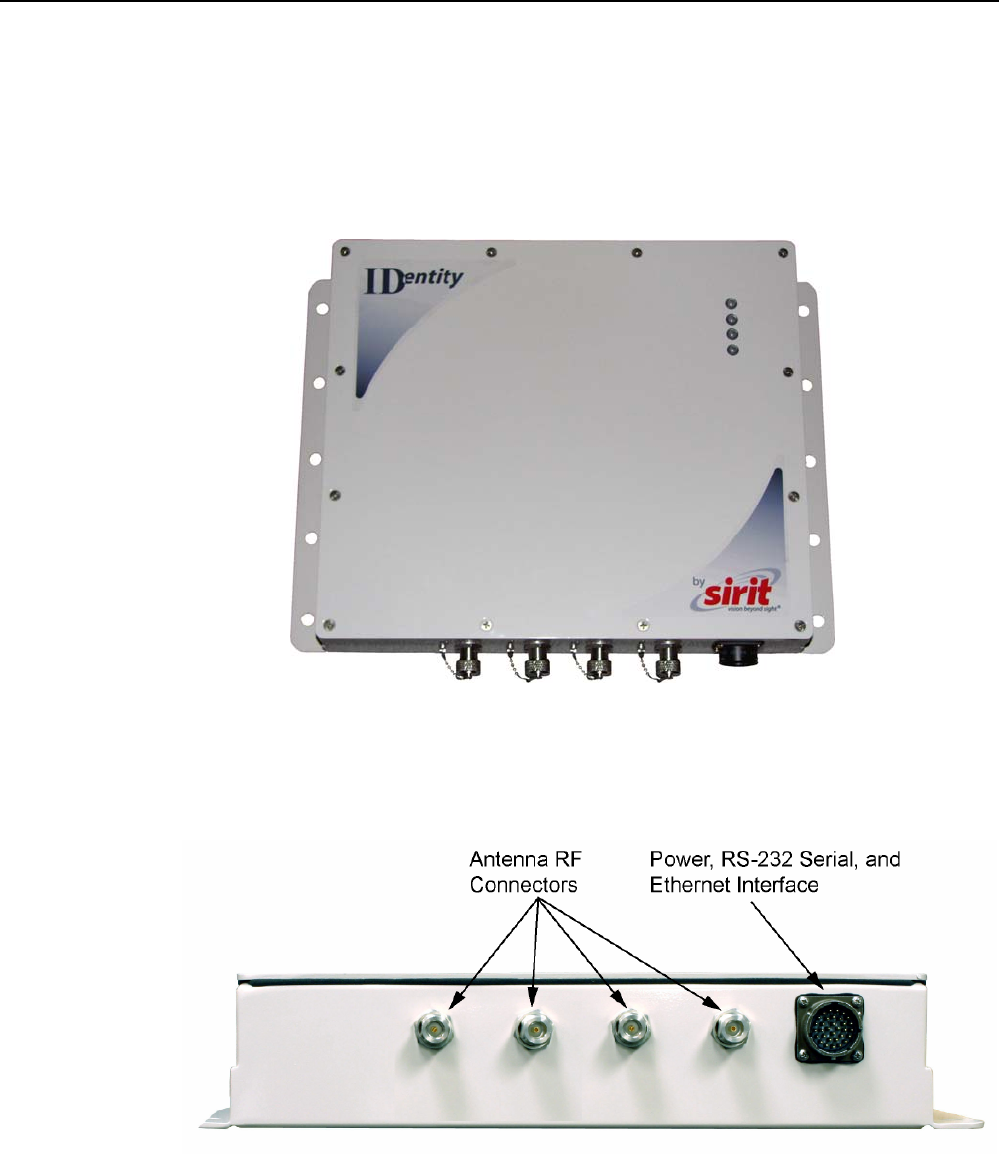
Figure 1 IDentity 6204 UHF Reader
As shown in the following figure, the IDentity 6204 reader supports four
Tx/Rx antennas (not shown). The reader is also equipped with RS-232 serial
and Ethernet interfaces.
Figure 2 IDentity 6204 Power and I/O Connections
1 2 3 4 5 6 7 8 9 Reader Overview
2 IDentity 6204 User’s Guide
1.2. Reader Software
The IDentity 6204 is shipped with two software applications that you can
use to configure and control the reader.
Reader Startup Tool (RST)
The RST is a Microsoft Windows based application you install on your
computer. With RST, you can view all readers on your network. After
selecting a reader, you can modify its communication, network, and
operational parameters. You can also read tags, review tag data, and
perform diagnostics. This RST is primarily intended for initially configuring a
reader prior to deployment. After deployment, use the Embedded Reader
Configuration Tool (RCT). Detailed information on the RST is provided in
Chapter 5.
Embedded Reader Configuration Tool (RCT)
This RCT is an embedded reader application that allows you to access your
readers across a LAN or WAN. Enter the IP address of the reader into your
Web browser and the RCT allows you to fully modify and operate the reader.
With the same functionality as the RST, this application allows you to modify
the reader’s communication, network, and operational parameters. You can
also read tags, review tag data, perform diagnostics, and upload new
software. This application is primarily intended for configuring and
managing deployed readers. Detailed information on the RCT is provided in
Chapter 6.
1 2 3 4 5 6 7 8 9 Reader Equipment Installation
IDentity 6204 User’s Guide 3
2 Reader Equipment Installation
2.1. Mechanical Installation
The IDentity 6204 is available with two mounting flanges suitable for most
pole and wall mount applications. Any mounting surface must be able to
support a minimum static load of 11.0 pounds (5 kg) plus any additional
live load due to environmental conditions.
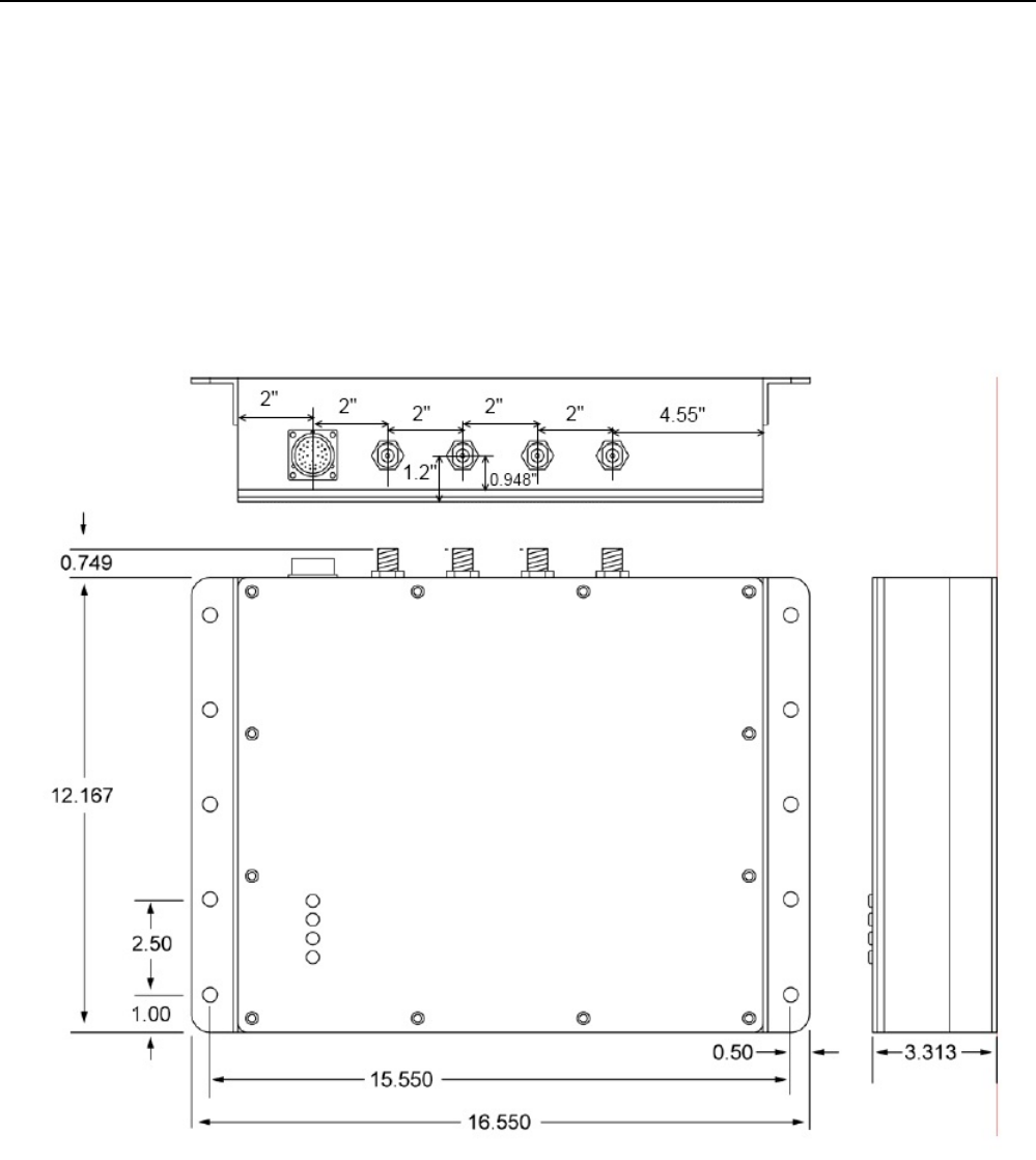
Figure 3 IDentity 6204 Mechanical Dimensions and Mounting Hole Locations (Dimensions in Inches)

1 2 3 4 5 6 7 8 9 Reader Equipment Installation
4 IDentity 6204 User’s Guide
To mount the IDentity 6204 reader assembly, refer to Figure 3 and perform
the following:
1 Prepare the mounting surface to accept the 10 mounting bolts. The
hole pattern should match that shown in Figure 3 and the mounting
surface must be able to support 11 lbs (5 kg).
2 Mount the reader.
3 Locate the Interface Cable.
4 Connect the cable to the reader’s bulk head connector and twist to lock
in place.
5 Connect the antenna cables (see Figure 4).
6 Adjust the angle of the antennas and tighten the hardware.
WARNING: FCC Radiation Exposure Statement. The antennas used for this transmitter
must be installed to provide a separation distance of at least 1 meter from all
persons and must not be co-located or operating in conjunction with any other
antenna or transmitter.
1 2 3 4 5 6 7 8 9 Reader Equipment Installation
IDentity 6204 User’s Guide 5
2.2. Electrical Installation
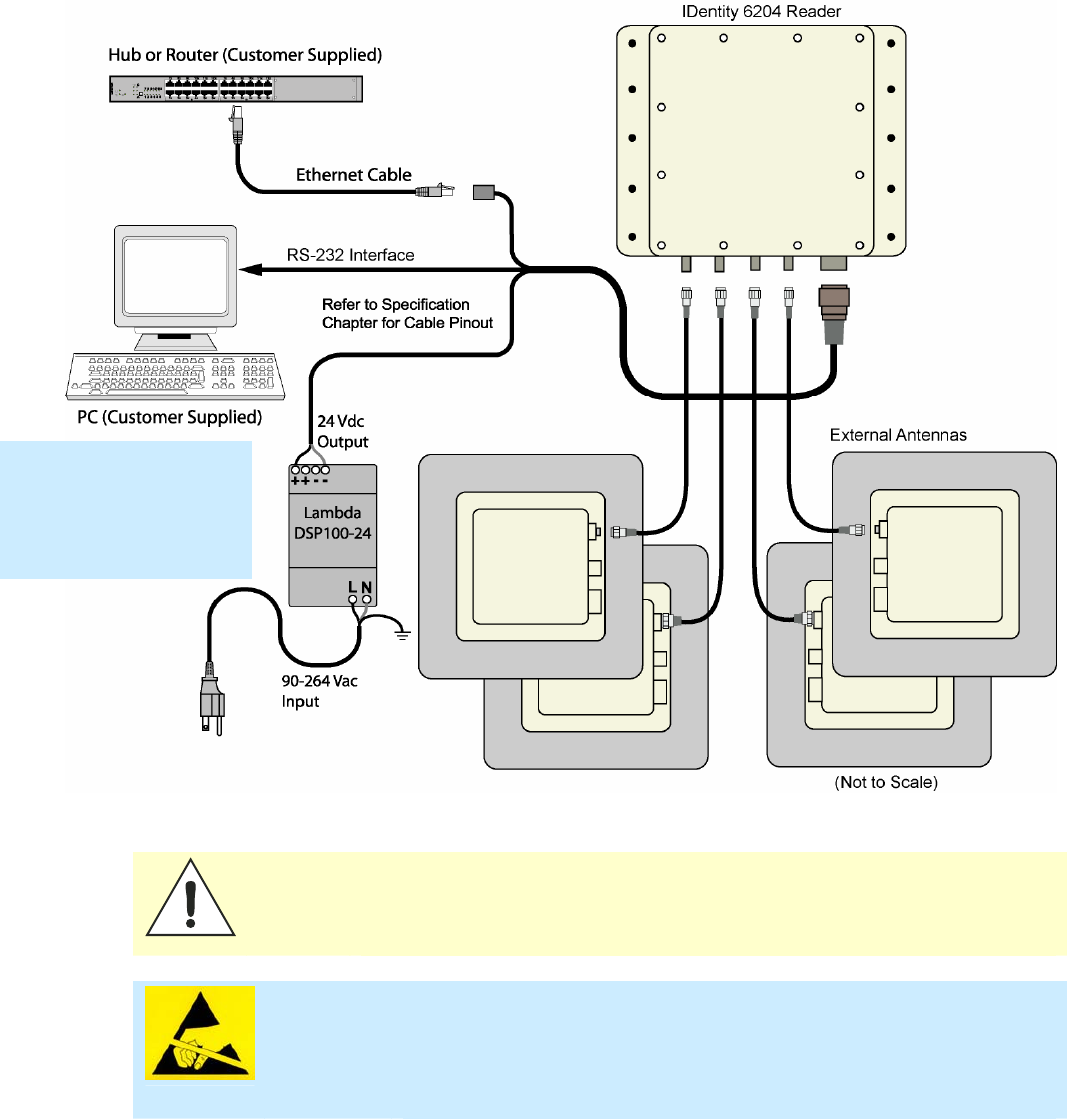
A general installation diagram is shown in the following figure. Refer to
Chapter 7 – Specifications for specific information.
Figure 4 IDentity 6204 Electrical Connections
Caution: The IDentity 6204 is designed to meet the regulatory requirements in those
jurisdictions in which it is offered. Changes or modifications not expressly
approved by Sirit Technologies for compliance could void the user's authority
to operate the equipment.
ATTENTION IDentity 6204 antenna ports may be susceptible to damage from static
discharge or other high voltage. Use proper Electrostatic Discharge
(ESD) precautions to avoid static discharge when handling or making
connections to the IDentity 6204 reader antenna or communication ports.
Equipment failure can result if the antenna or communication ports are
subjected to ESD.
Installation Notice
Installation of the IDentity
6204 is only to be
performed by trained, Sirit
approved personnel.
1 2 3 4 5 6 7 8 9 Reader Equipment Installation
6 IDentity 6204 User’s Guide
2.2.1. Connecting the Serial Port
The IDentity 6204 RS-232 serial port provides communication up to
115200 Baud. This port is accessed through the bulkhead connector on the
reader. If you are using the serial port for reader communication, connect a
serial cable from the COM port on your PC to the serial port on the reader.
See Figure 2 for location of the connector.
Refer to the Chapter 8 – Specifications for details on the bulkhead
connector.
2.2.2. Connecting and Configuring the Ethernet Port
The IDentity 6204 Ethernet port is accessed through the bulkhead
connector. If you are communicating with your reader across a Local Area
Network (LAN), connect an Ethernet cable from your hub or router to the
bulkhead connector.
By default, the reader is configured to use a DHCP server to obtain its IP
address and related information. In the event a DHCP server is unavailable,
the reader will boot with an IP address in the 169.254.x.x subnet.
In the absence of other readers on the same network, and if no other
network traffic is observed which references 169.254.1.1, the reader will
select that address; otherwise, it will select a random address on the
169.254.x.x subnet.
IP address settings can be changed using RST. Refer to the View or Change
the Reader’s Network Settings section in Chapter 5.
Refer to the Chapter 8 – Specifications for details on the bulkhead
connector.

1 2 3 4 5 6 7 8 9 Reader Equipment Installation
IDentity 6204 User’s Guide 7
2.2.3. Connecting the External Antenna
The IDentity 6204 supports four external Tx/Rx antennas. Connect the
antenna to the antenna port located on the bottom of the reader.
Refer to Chapter 7 – Specifications for specific information regarding the
external antenna and antenna cable.
Caution: The IDentity 6204 is equipped with four external RF ports. If activated, these RF
ports must be properly terminated with a 50 ohm load or a functional UHF
antenna before power up. Always power down the reader before removing an
antenna or load from an RF port.
ATTENTION The IDentity 6204 antenna ports may be susceptible to damage from
static discharge or other high voltage. Use proper Electrostatic
Discharge (ESD) precautions to avoid static discharge when handling or
making connections to the IDentity 6204 reader antenna or
communication ports. Equipment failure can result if the antenna or
communication ports are subjected to ESD.
2.2.4. Connecting Digital Inputs/Outputs
The IDentity 6204 is equipped with a general purpose digital input/output
(I/O) port that provides four optically isolated 5-24 VDC input signals and
four open-collector output signals. The digital inputs can be used as general
purpose inputs or to trigger the reader for tag reading. These inputs can be
configured to provide an external read trigger from proximity sensors, photo
switches, or other devices.
The digital outputs can be used as general purpose outputs, to indicate tag
reading activity, or to indicate the reader is transmitting (RF On). The
outputs can also be configured to trigger conveyor gates or other access
control and sorting devices. For detailed information on configuring the
digital inputs and outputs refer to Chapter 7.
2.2.5. Connecting the Power
The IDentity 6204 operates on 24 Vdc provided through the bulkhead
connector on the rear of the reader. Connect the power supply to the reader
and connect the power supply to your 100–240 Vac, 50-60 Hz power
source. Allow 30 seconds for the reader to initialize.
Refer to the Chapter 8 – Specifications for details on the bulkhead
connector.
1 2 3 4 5 6 7 8 9 RST Software Installation
8 IDentity 6204 User’s Guide
3 Reader Startup Tool (RST) Software Installation
3.1. Installing RST Software
The IDentity 6204 is delivered with a Microsoft Windows application called
Reader Startup Tool (RST). You can use this application to initially configure
your reader as well as read and display tag data.
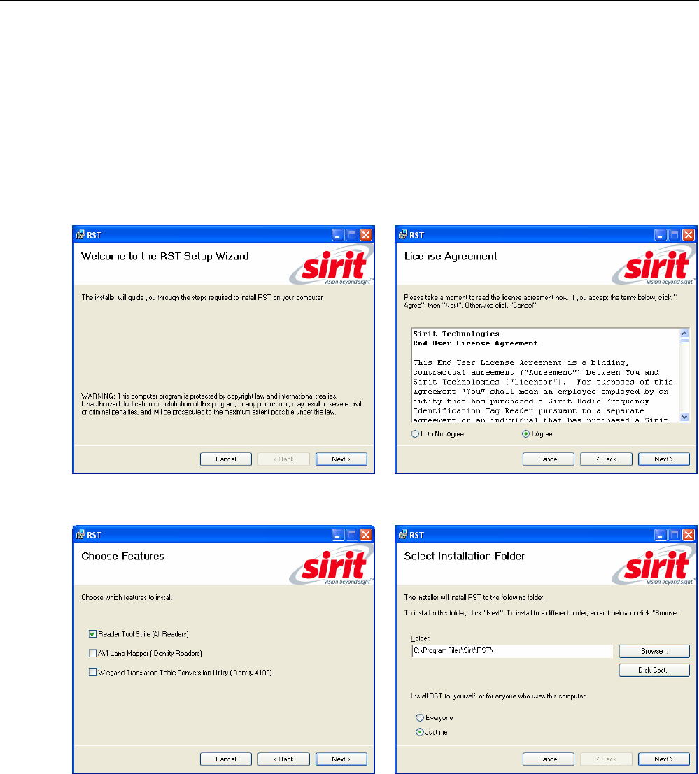
Install RST
1 To install RST, load your product CD and double-click the
RSTInstaller.msi file:
2 Press Next> 3 Read the License Agreement. Select
I Agree and press Next>
4 Select Reader Tool Suite. Press Next>. 5 Verify the path and folder where RST will
be installed. Press Next>.
1 2 3 4 5 6 7 8 9 RST Software Installation
IDentity 6204 User’s Guide 9
5 Press Next>. 6 After the installation completes, press
Close.
3.2. Windows 7 Setup
If you have a Windows 7 operating system, your firewall may block UDP
traffic and consequently RST may not discover your readers. Perform the
following to configure your system:
For Microsoft Firewall
1 Log into your computer as Administrator.
2 Navigate to the Control Panel and select
Control Panel → System and Security.
3 Select Allow a program through Windows firewall.
4 Scroll down the list and locate Startup Tool, check it, and press OK.
5 If Startup Tool is not in the list, press Allow another program.
6 Locate Startup Tool, check it, and press OK.
7 Restart RST and it should discover readers.
For Third-Party Firewalls
1 Log into your computer as Administrator.
2 Set your firewall to allow RST to receive UDP traffic on port 50000 and
50001.
1 2 3 4 5 6 7 8 9 RST Software Installation
10 IDentity 6204 User’s Guide
3.3. Reader Startup
To begin using your reader, open the RST application.
Open RST
1 From your Windows desktop, select:
Start→Programs→Sirit→Reader Startup Tool (RST)
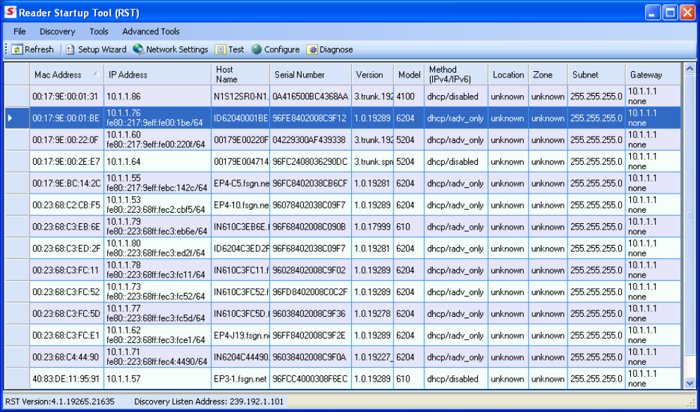
2 If this is the first time starting the RST application, you may receive a
Windows Security Alert. This warning indicates that the firewall is
blocking the RST application.
3 If the warning window is hidden under the RST windows, collapse the
RST window.
1 2 3 4 5 6 7 8 9 RST Software Installation
IDentity 6204 User’s Guide 11
4 Press Unblock.
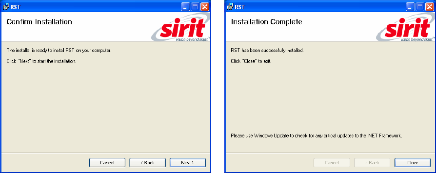
5 Press Refresh on the RST
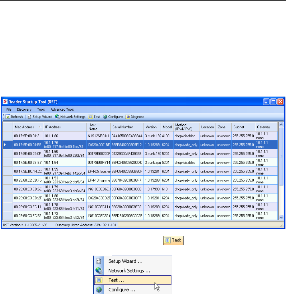
6 The RST main page will display any readers currently connected to the
network.
3.4. Initial Reader Setup
To configure a specific reader, perform the following:
Reader Setup
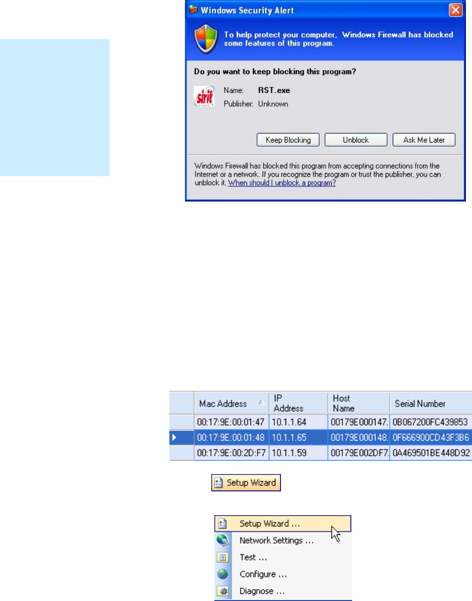
1 Select the reader on the main RST page by clicking the button to the left
of the reader Mac address.
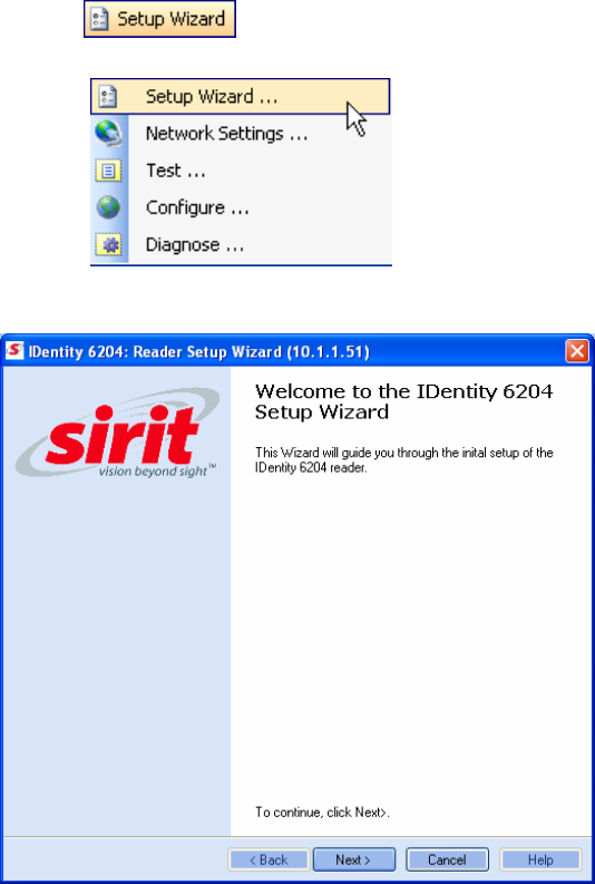
2 Press the button on the RST tool bar or select Setup
Wizard from the Tools pull-down menu.
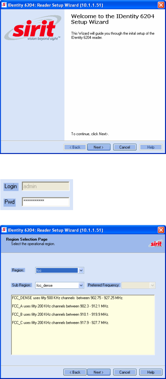
3 The IDentity 6204 Reader Setup Wizard (RSW) is displayed.
NOTE:
Earlier versions of
Microsoft Windows™
may not provide the
Security Alert popup.
IF RST does not
discover your reader,
check your Windows
Firewall/Security
settings.
1 2 3 4 5 6 7 8 9 RST Software Installation
12 IDentity 6204 User’s Guide
4 Press Next> and enter the Login (admin) and Password. If this is the
first time configuring your reader, enter: readeradmin.
5 After entering your Login and Password, press Next>
1 2 3 4 5 6 7 8 9 RST Software Installation
IDentity 6204 User’s Guide 13
6 Select the Region and Sub Region and press Next>.
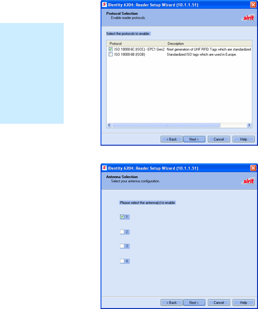
7 Select the protocol of the tags you will be reading and press Next>.
8 Select the antennas you will be installing and press Next>.
Custom Setup
If your installation
type differs from one
of the choices shown
in the Setup Wizard,
you can always
customize your setup
later using the
embedded web
interface capability.
See the Advanced
Setup chapter in this
guide for more
information.
1 2 3 4 5 6 7 8 9 RST Software Installation
14 IDentity 6204 User’s Guide
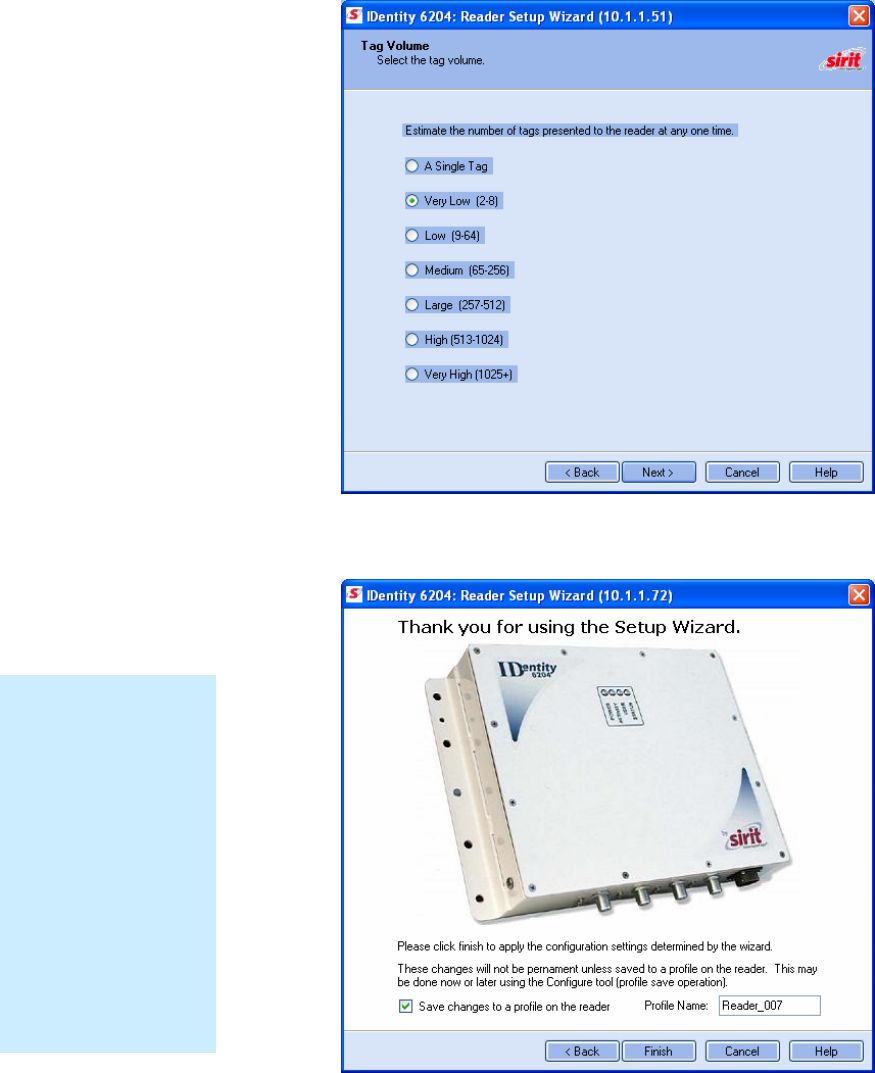
9 Estimate the number of tags that will be presented to the reader at any
one time and press Next>.
10 It is highly recommended that you save the reader setup as a profile.
Select Save changes to a profile…, enter a Profile Name, and press
Finish to complete the initial reader setup.
Saving Reader Setup
Reader setup
information should be
saved as a profile. In
the event that you
need to reboot or
power down a reader,
the reader setup can
be quickly reloaded
by loading the profile.
If you don’t save the
reader setup, you can
loose the information
if the reader is
rebooted.
1 2 3 4 5 6 7 8 9 Reader Operation
IDentity 6204 User’s Guide 15
4 Reader Operation
4.1. Basic Operation with RST
The IDentity 6204 can be operated either from the RST application or by
logging directly into the reader’s embedded Reader Configuration Tool
(RCT). To operate the reader from RST, perform the following:
Open RST
1 From your Windows desktop, select:
Start→Programs→Sirit→Reader Startup Tool (RST)
2 Select a reader and press on the RST tool bar or select Test
from the Tools pull-down menu.
1 2 3 4 5 6 7 8 9 Reader Operation
16 IDentity 6204 User’s Guide
3 The Reader Test Tool (RTT) is displayed.
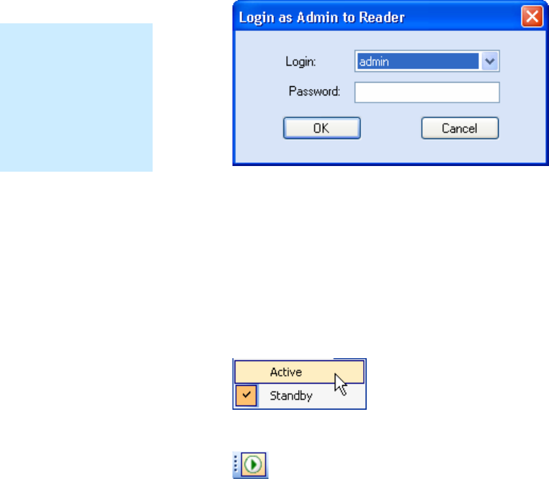
4 Login to the reader. From the pull-down menu select Reader→Login….
5 For administrator login, select admin. The initial password (Pwd) is
readeradmin. See Advanced Setup section to change the password.
6 Verify the Operating Mode is set to Active. From the pull-down menu
select Operating Mode→Active.
7 Select the Tag Performance tab and press Start.
8 Place tags in front of antenna and verify tags are read and displayed.
1 2 3 4 5 6 7 8 9 Reader Operation
IDentity 6204 User’s Guide 17
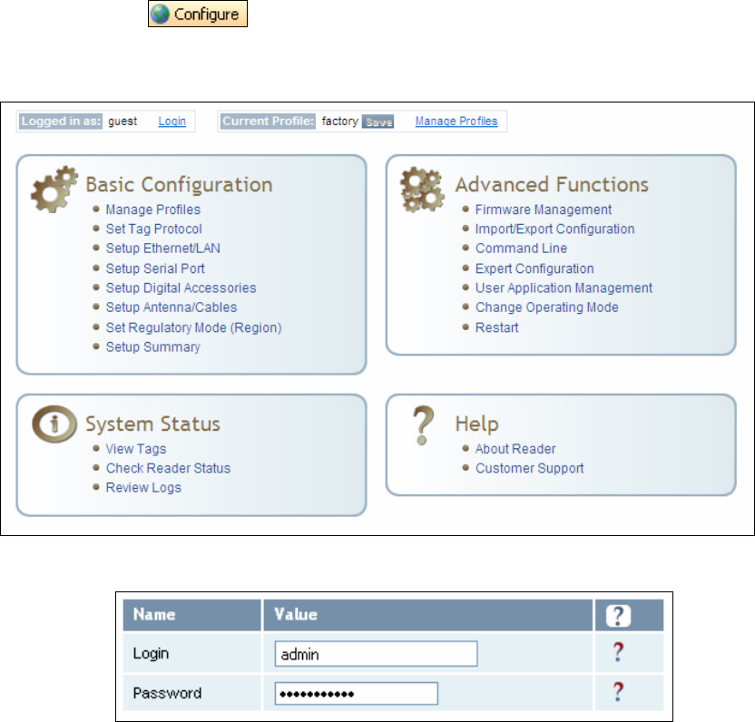
4.2. Deployed Reader Operation with RCT
Once your readers are deployed, you can access them directly using the
embedded Reader Configuration Tool (RCT). To access a particular reader,
perform the following:
1 Enter the reader’s IP address into your web browser, press the
button on the RST tool bar or select Configure from the
Tools pull-down menu.
2 The reader’s RCT interface is displayed.
3 Log into the reader. Press Login for the login screen.
4 The default login is guest. If you need administrator privileges, login as
admin and enter readeradmin as the password.
5 Press Submit.
6 Select Basic Configuration →Setup Antenna/Cables to configure the
antennas, gain, and power settings.
1 2 3 4 5 6 7 8 9 Reader Operation
18 IDentity 6204 User’s Guide
7 Select Advanced Functions →Change Operating Mode to verify the
reader is in the proper mode.
8 Select Basic Configuration →Set Tag Protocol to verify the reader is
configured for the proper tag protocol.
9 Press System Status →View Tags to view tag data.
10 If you need to configure additional changes to your reader, refer to
Chapter 7 – Reader Configuration Tool for information on using RCT to
adjust configuration variables and parameters.
1 2 3 4 5 6 7 8 9 Reader Startup Tool
IDentity 6204 User’s Guide 19
5 Reader Startup Tool (RST)
The Reader Startup Tool (RST) provides an easy-to-use interface for the
IDentity 6204 configuration and operation functions. This application
resides on your Windows based computer and allows you to perform the
following:
h View all readers on the network
h Launch the Reader Setup Wizard to configure a reader
h View and change a reader’s network settings
h Add a new reader to the network
h Launch Reader Test Tool to perform basic reader/tag operations
h Launch Reader Diagnostic Tool to view statistics, alarms, and reports
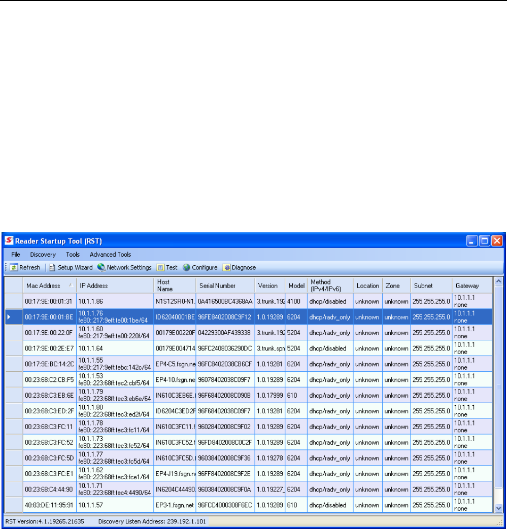
5.1. View Readers on the Network
When RST starts up, all readers currently connected to the network and
powered up are displayed.
1 2 3 4 5 6 7 8 9 Reader Startup Tool
20 IDentity 6204 User’s Guide
5.2. Configure Reader with the Setup Wizard
The Reader Setup Wizard is used to initially configure your reader for
operation. With this application, you can select the following:
h Installation type
h Regulatory region and sub-region
h Protocol
h Number of antennas
h Estimated tag volume
To initially configure your reader perform the following:
1 Press the button on the RST tool bar or select Setup
Wizard from the Tools pull-down menu.
2 The IDentity 6204 Reader Setup Wizard (RSW) is displayed.
3 Refer to Chapter 2 – Reader Configuration for detailed instructions on
using the Reader Setup Wizard.
1 2 3 4 5 6 7 8 9 Reader Startup Tool
IDentity 6204 User’s Guide 21
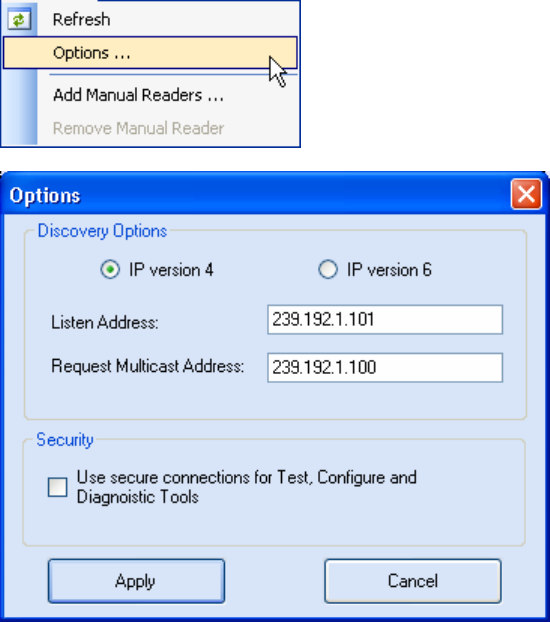
5.3. Customize Discovery Options
You can customize the reader discovery options including the Listen
Address and Request Multicast Address.
h Listen Address – Address that RST uses to listen for UDP discovery
packets from the reader. This is customizable on the reader.
h Request Multicast Address –Address used by RST to send out the UDP
update request packets. This is customizable on the reader.
In addition, you can select if you want a secure connection for the Test,
Configure, and Diagnostic Tools. This connection uses the HTTPS protocol
and any data transferred between devices is encrypted.
1 On the RST tool bar select Options from the Discovery pull-down menu.
2 Select either IP version 4 or IP version 6.
3 Enter the Listen Address and Request Multicast Address as required.
4 Select whether you require a secure connection for the Test, Configure,
and Diagnostic Tools.
5 Press Apply.
1 2 3 4 5 6 7 8 9 Reader Startup Tool
22 IDentity 6204 User’s Guide
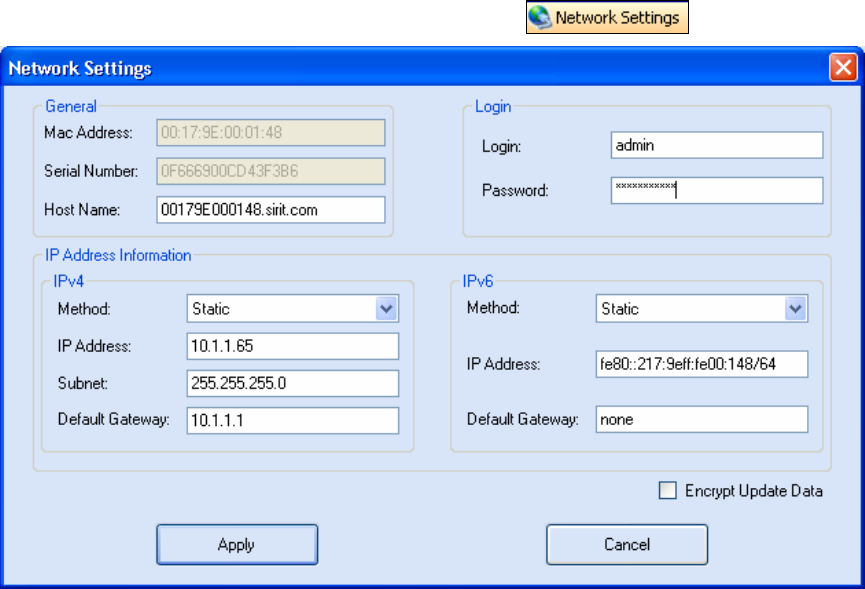
5.4. View or Change the Reader’s Network Settings
1 From the RST main page, press the button.
2 Verify the IP Address, Subnet, and Default Gateway are correct.
3 If Method: DHCP is selected these fields will be locked.
4 If required, change the values.
1 2 3 4 5 6 7 8 9 Reader Startup Tool
IDentity 6204 User’s Guide 23
5.5. Reader Test Tool (RTT)
The Reader Test Tool (RTT) is primarily designed for new users to test
reader operation and perform a few basic reader functions. With RTT, you
can perform the following:
h Read tags
h Issue commands to the reader and view the responses
h Run macros
h Observe reader events
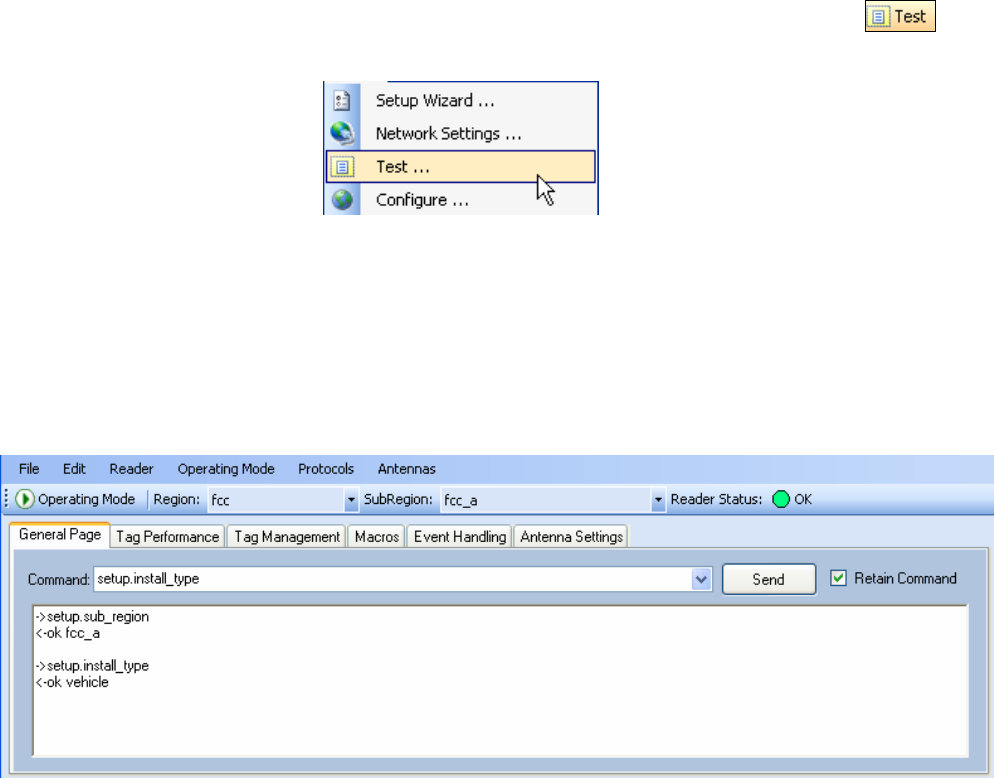
h To access the Reader Test Tool, select a reader and press on
the RST tool bar or select Test from the Tools pull-down menu.
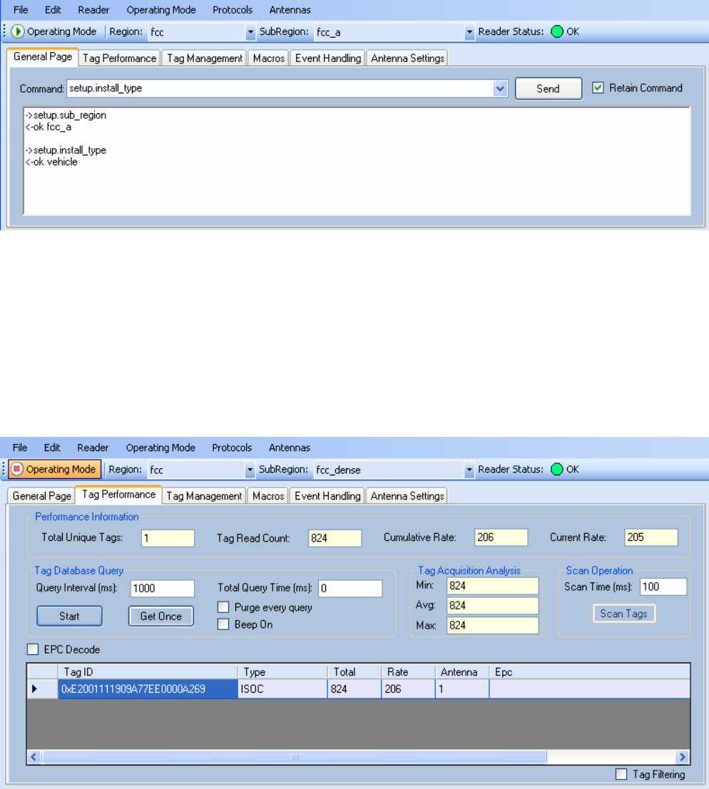
5.5.1. General Page
The General Page allows you to issue commands to the reader and view
any responses. From the pull-down menus, you can also login to the reader,
change the operating mode, select another protocol, and select which
antennas are active.
1 2 3 4 5 6 7 8 9 Reader Startup Tool
24 IDentity 6204 User’s Guide
Login to Reader
To login to the reader, perform the following:
1 From the pull-down menu, select Reader→Login….
2 Select the type of Login from the pull down. The default login is guest. If
you need administrator privileges, login as admin.
3 Enter your Password. Enter readeradmin as the password if you logged
in as admin.
4 Press OK.
Select Operating Mode
From the pull-down menu, select Operating Mode→<Active | Standby>
or, press the Operating Mode select button on the left side of the tool bar.
h Active – Reader is continuously attempting to singulate tags and
automatically reports any singulated tag via an asynchronous event
notification on the event channel.
h Standby – Reader is not transmitting any RF energy, unless processing
a tag related command. The transmitter is enabled at the beginning of
the command processing, protocol operations required for the
command are performed, and then the RF transmitter is turned off.
Default Admin
Password
Sirit recommends
changing the default
Admin password once
installation,
configuration, and
testing are complete.
1 2 3 4 5 6 7 8 9 Reader Startup Tool
IDentity 6204 User’s Guide 25
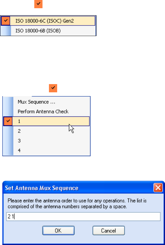
Select Protocol
You can activate one or more protocols on the IDentity 6204 using RST.
From the pull-down menu, select Protocols→<protocol>. Active protocols
are indicated by .
Antenna Selection
You can select the ports that have antennas connected and which antennas
are active. Perform the following:
1 From the pull-down menu, select Antennas→<n>. Active antennas
are indicated by .
2 You can also select the order in which antennas are activated. From the
pull-down menu, select Antennas→Mux sequence....
3 Enter the antenna numbers in the order to be activated.
4 Press OK.
1 2 3 4 5 6 7 8 9 Reader Startup Tool
26 IDentity 6204 User’s Guide
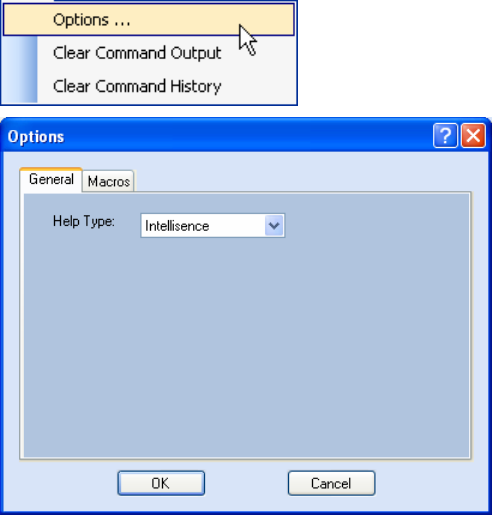
Set Reader Options
You can setup other reader options including help type macro highlighting.
From the pull-down menu, select Edit→Options.
1 2 3 4 5 6 7 8 9 Reader Startup Tool
IDentity 6204 User’s Guide 27
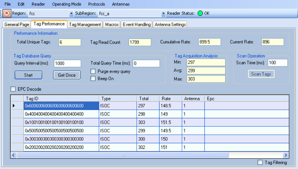
5.5.2. Tag Performance Page
The Tag Performance page is used to test the reader performance.
To initiate a timed test, enter the length of test (in ms) into the Total Query
Time field. For example, to verify to number of tags read in a 30-second
interval, select Active Operating Mode, enter 30000, and press the Start
button. The test will complete after 30 seconds and the output statistics are
updated for the query time.
Output statistics are read-only and include: Total Unique Tags, Tag Read
Count, Cumulative Rate, and Current Rate.
Detailed descriptions of the various Tag Performance fields and functions
are provided in the following sections.
Tag read controls are provided by the Tag Database Query and Scan
Operation blocks. Use the Query controls when the reader is in Active
mode. Use the Scan Operation controls when in Standby mode.
Tag and reader performance data is provided in the Performance
Information and Tag Acquisition Analysis blocks.
1 2 3 4 5 6 7 8 9 Reader Startup Tool
28 IDentity 6204 User’s Guide
Performance Information
Total Unique Tags – Number of unique tags in the tag database.
Tag Read Count – Total number of tags read (including repeat reads).
Cumulative Rate – Cumulative read rate in tags/second since the Start
button was pressed.
Current Rate – Current read rate in tags/second.
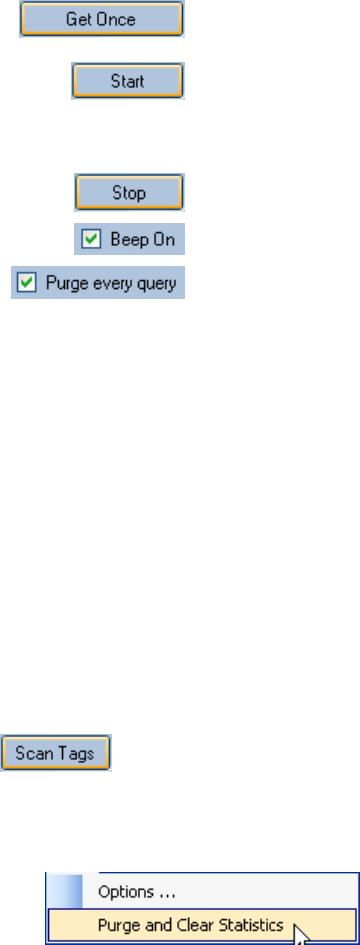
Tag Database Query Controls
Click to retrieve the current information from reader’s
tag database.
Click to query the tag database every Query Interval
(ms) for a total time of Total Query Time (ms). Do not
set the interval less than 500. If Total Query Time is
set to 0, query continues indefinitely.
Click to stop automatic query.
Indicates current read rate with audible tone.
Check to purge the reader’s tag database after each
query. Refer to the IDentity 6204 Protocol Reference
Guide for more information on the tag database.
Tag Acquisition Analysis
The Tag Acquisition Analysis fields provide the minimum, maximum, and
average number of times each tag was read. For example, assume five tags
(A, B, C, D, and E) are read 107, 59, 223, 187, and 94 times respectively.
The displayed values are as follows:
Min = 59
Avg = 134
Max = 223
Scan Operation
Scan time (ms) – Enter the duration of reader operation in milliseconds.
After this time expires, the tag information is displayed.
Press this button to activate the reader.
Purge and Clear Reader Statistics
Select the reader and then select Edit→Purge and Clear Statistics.
1 2 3 4 5 6 7 8 9 Reader Startup Tool
IDentity 6204 User’s Guide 29
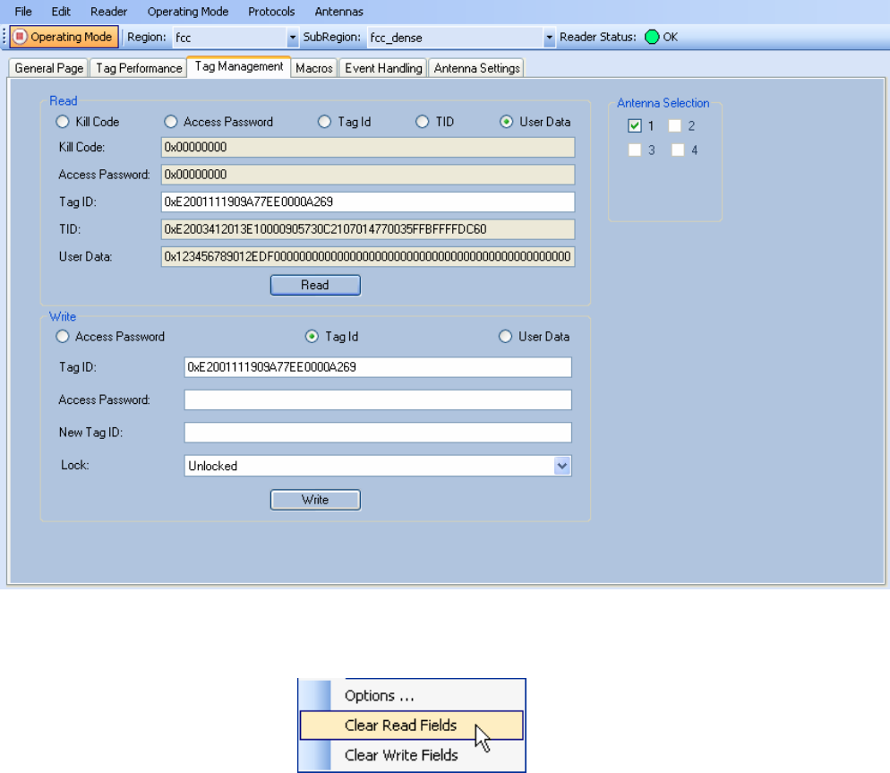
5.5.3. Tag Management Page
The Tag Management page is used for reading individual fields on a single
tag as well as writing the access password and locking a tag. The Read
button will cause the reader to singulate and read a tag in the selected
antennas’ RF field. Specific fields you can read include:
h Kill Code
h Access Code
h Tag ID
h TID
h User Data
Clear Read and Write Fields
To clear the Read or Write fields, select Edit→Clear….
1 2 3 4 5 6 7 8 9 Reader Startup Tool
30 IDentity 6204 User’s Guide
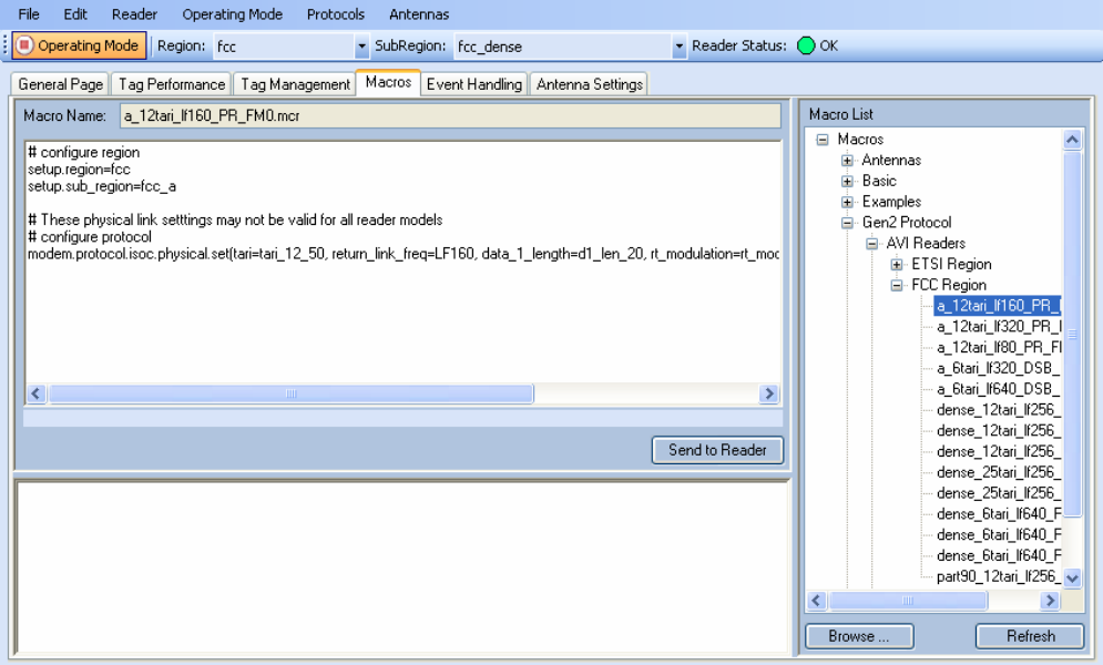
5.5.4. Macros Page
The Macros page allows the reader to manage macro files. The macros are
provided by Sirit or can be written by the end user. Some of the macros
provided are dependent on the operating region of the reader.
A macro (script or command file) is a text file that contains one or more
reader commands. These commands are used to configure the reader to a
known configuration. The Macros can contain variables. These variables are
resolved by a dialog box (Macro Variables) that appears when the Send to
Reader button is selected. The syntax of a variable is:
[$variable_name]
During execution, the variable is replaced with user entries into the Macro
Variables dialog box. Macros can be edited with any text editor including
Windows Notepad.
1 2 3 4 5 6 7 8 9 Reader Startup Tool
IDentity 6204 User’s Guide 31
Macro Input sub-window
The Macro Input window shows the current script that will be sent to the
reader when the Send to Reader button is selected. The text in the Macro
Input window can be edited prior to being sent to the reader.
Macro Output sub-window
The Macro Output window is updated after the Send to Reader button is
selected. Look at this window to verify that each command line in a script
executed correctly. Look for the −−>> ok response from the reader for each
command line.
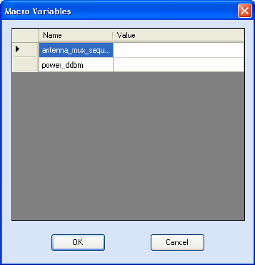
Macro Variables Dialog box
When a macro is sent to the
reader, the values for variables
must be resolved via this Windows
Dialog box. You can [tab] to each
value field and enter the desired
value.
For example, one macro can be
used for two different applications
by using variables for antenna
selection and transmit power.
Macro Example
To configure the reader for FCC, Part 90 Dense operation, send the
following macro (part90_6tari_lf640_PR_M2.mcr):
# configure region
setup.region=fcc
setup.sub_region=fcc_part90
# set frequency
setup.advanced.preferred_frequencies=915950
# configure protocol
modem.protocol.isoc.control.auto_phy.enable=false
modem.protocol.isoc.physical.set(tari=tari_06_25,
return_link_freq=LF640, data_1_length=d1_len_20,
rt_modulation=rt_mod_pr,
tr_encoding=tr_enc_miller_2,interrogator_mode=dense)
1 2 3 4 5 6 7 8 9 Reader Startup Tool
32 IDentity 6204 User’s Guide
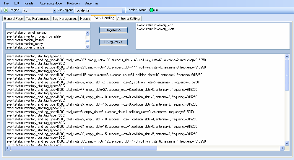
5.5.5. Event Handling Page
The Event Handling page allows you to register for Reader Events. After
registration, events are displayed with the newest on the bottom and the
most recent event will scroll to the bottom of the window. Individual events
or a group of events can be registered. For detailed information on
individual events, refer to Chapter 18 – Events Namespace of the IDentity
6204 Protocol Reference Guide.
Registering for an individual event
To register for an individual event, either type the event name or select an
event from a pull-down list.
Registering for a group of events
Registering for event.error events, will cause the reader to autonomously
send all events in the event.error namespace to the RTT program and be
displayed in the window of this page. Enter event.error in the Events: field
and press the Register button. The Clear button can be selected at any
time to clear the window.
1 2 3 4 5 6 7 8 9 Reader Startup Tool
IDentity 6204 User’s Guide 33
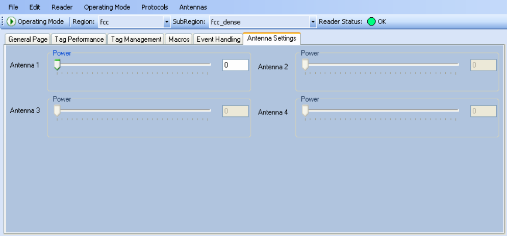
5.5.6. Antenna Settings Page
The Antenna Settings page allows you to adjust the power settings for each
antenna. Only the controls for those antennas that are connected are
activated.
1 2 3 4 5 6 7 8 9 Reader Startup Tool
34 IDentity 6204 User’s Guide
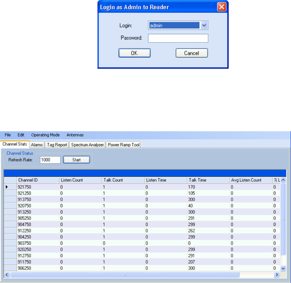
5.6. Reader Diagnostics Tool (RDT)
The Reader Diagnostic Tool (RDT) is to be used by Sirit trained technicians
to troubleshoot and diagnose various reader issues. Administrator login is
required.
To use RDT, you must login as an administrator, perform the following.
When you first start RDT, the following login will appear:
Enter your Password. Enter readeradmin or your current administrator
password. Press OK.
5.6.1. Channel Statistics
The Channel Stats page shows details of channel changes. This page is
typically used to observe regional behavior.
1 2 3 4 5 6 7 8 9 Reader Startup Tool
IDentity 6204 User’s Guide 35
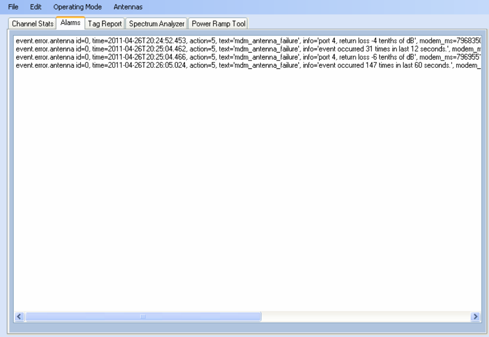
5.6.2. Alarms
The Alarms page is used to capture autonomous alarms generated by the
reader during normal operation. The alarms are defined as autonomous
reader events for the following namespaces:
event.error
event.warning
1 2 3 4 5 6 7 8 9 Reader Startup Tool
36 IDentity 6204 User’s Guide
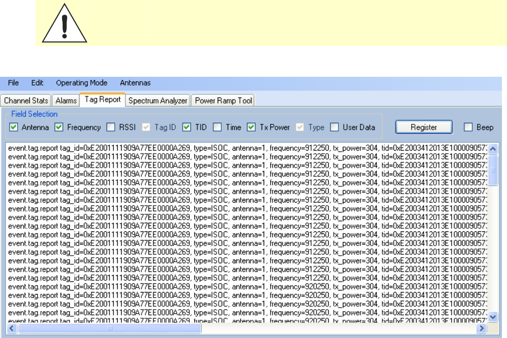
5.6.3. Tag Report
The Tag Report page is used to view specific information for each tag
singulation. This feature provides detailed attributes of tag singulations
such as tag power (RSSI) and on which antenna that tag singulated.
Caution: Use of this tool can adversely affect tag reader performance, particularly if many
tag fields are enabled. Use the RTT->Tag Performance page for normal tag
performance testing.
1 2 3 4 5 6 7 8 9 Reader Startup Tool
IDentity 6204 User’s Guide 37
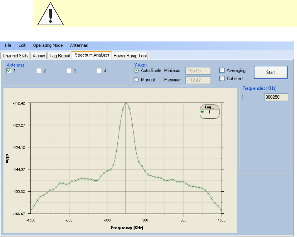
5.6.4. Spectrum Analyzer
The Spectrum Analyzer allows you to examine the spectral composition of
the radio waves in your surrounding environment. This feature provides a
graphical representation of the current spectral RF noise in units of dBm
with a range of 0 to -120 dBm. This feature is intended for expert users to
verify RF environmental conditions during an installation.
Caution: Using this feature during normal reader operation can significantly degrade
tag reading performance.
1 2 3 4 5 6 7 8 9 Reader Startup Tool
38 IDentity 6204 User’s Guide
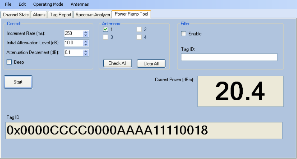
5.6.5. Power Ramp Tool
The Power Ramp Tool determines the minimum power to activate a tag and
can help determine tag quality. This activation power level can help
determine the read range at various attenuation levels and, for AVI
applications, can help determine the "read-zone" or an antenna pattern.
The tool starts by configuring the reader to start transmitting at a high
attenuation level (usually maximum allowed for reader) and decrements the
level until it observes a response from the tag. The transmitter is turned off
and the minimum value to activate the tag for a given antenna and distance
is reported.
The Power Ramp controls include:
h Increment Rate (ms) – Time tool stays at a particular power level
before incrementing to the next power level.
h Initial Attenuation Level (dBm) – Starting attenuation level.
h Attenuation Decrement (dBm) – Step-size for attenuation
decrement.
h Antennas section allows you to select which antenna(s) to test with.
h Filter section allows you to apply a filter to only look for a particular tag.
1 2 3 4 5 6 7 8 9 Reader Configuration Tool
IDentity 6204 User’s Guide 39
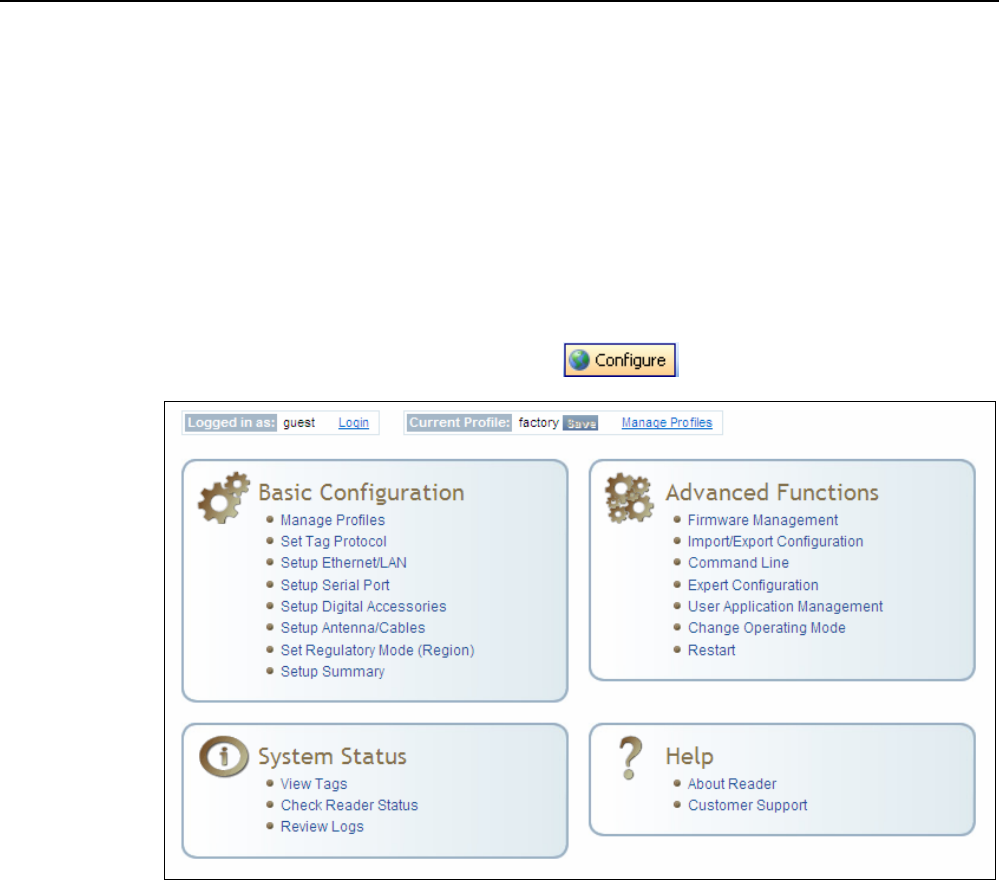
6 Embedded Reader Configuration Tool (RCT)
The Embedded Reader Configuration Tool (RCT) allows you to access your
reader across the internet by entering the reader’s IP address into your web
browser. With the RCT, you can fully configure your reader for operation in a
variety of applications and environments. With this application, you can
perform the following:
h Basic Configurations
h Advanced Configurations
h Check System Status
h Access the online Help
To access the RCT, press the button on the main RST page.

1 2 3 4 5 6 7 8 9 Reader Configuration Tool
40 IDentity 6204 User’s Guide
6.1. Basic Configuration
With the Basic Configuration functions you can perform the following:
h Manage reader profiles
h Set tag protocols
h Setup the Ethernet/LAN configuration
h Setup the serial port
h Setup digital accessories
h Setup antennas
h Set regulatory modes
6.1.1. Configuration Page Header
Each page displayed by the RCT has the following header.
This header provides pull-down menus for each of the configuration
function categories. Additional functions include the user login and the
currently loaded reader profile.
Login
The reader’s default user level is guest. However, a user can login as admin.
If not logged in as admin, the default level is always guest.
The guest login level provides read-only access to the reader. Clients that
login in at the guest level can read the settings of the reader and can
access the tags that the reader has inventoried. Clients at this level cannot
change the configuration of the reader.
The admin login level provides read-write access to the reader. Clients that
login in at the admin level can read and write the settings of the reader and
can access the tags that the reader has inventoried.
Logout
After logging in as admin, the Logout button logs you out of the reader.
Logging out automatically sets the login level to guest.
Profile:
Profile is the currently active profile in the reader. Refer to the Manage
Profiles section for detailed information on reader profiles.
1 2 3 4 5 6 7 8 9 Reader Configuration Tool
IDentity 6204 User’s Guide 41
Save
The Save button saves the reader's current configuration to the specified
profile. Refer to the Manage Profiles section for detailed information on
reader profiles.
Manage Profiles
This link allows you to list, save, and delete profiles. Refer to the Manage
Profiles section for detailed information on reader profiles.
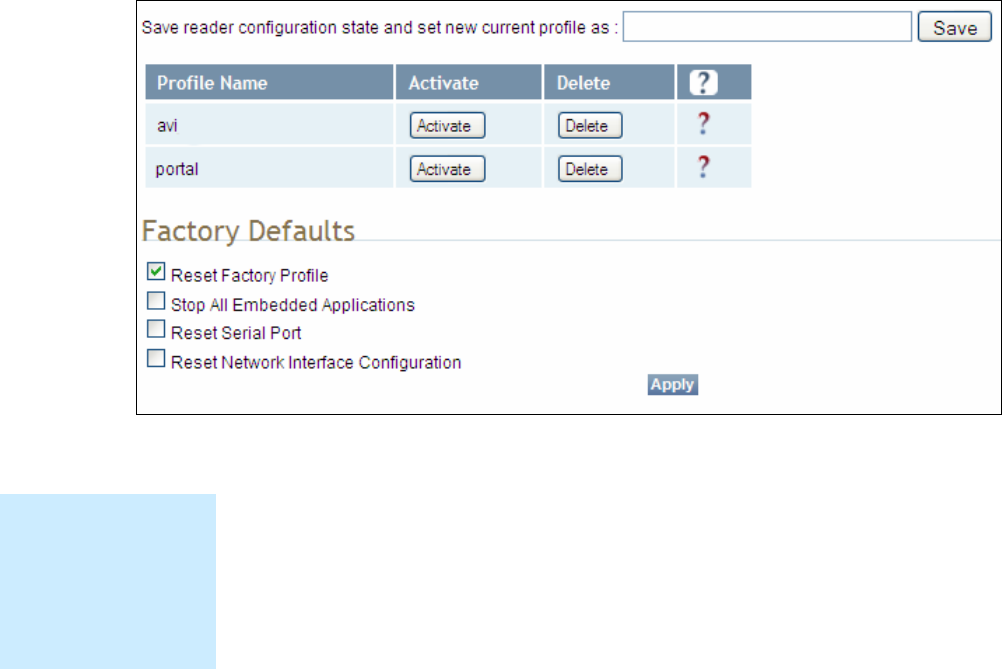
6.1.2. Manage Profiles
The reader’s configuration is stored in a profile. A profile contains the
setting of all the configuration variables in the reader. The reader can
support up to 8 unique profiles. Detailed information about reader profiles
is provided in Chapter 4 – Reader Behavior of the IDentity 6204 Protocol
Reference Guide.
The Manage Profiles page provides a list of all profiles stored in the reader.
Save a Profile
To save your current reader configuration under a new profile, enter a
profile name and press Save. The new profile will appear in the Profile
Name list. Profile names must consist of the characters A - Z, a - z, 0 - 9, '-'
or '_' and must be between 1 and 32 characters in length. The reader can
store up to 8 different profiles.
Profile Names
The profile name
factory is reserved
and cannot be used.
This profile is a read
only profile.

1 2 3 4 5 6 7 8 9 Reader Configuration Tool
42 IDentity 6204 User’s Guide
Activate a Profile
To activate a previously saved profile, press the Activate button beside the
profile name. The selected profile will be loaded into the reader.
Delete a Profile
To delete a previously saved profile, press the Delete button beside the
profile name. This is a destructive operation. Once a profile is deleted, it
cannot be recovered.
Reset to Factory Default
In addition to managing reader profiles, you can also reset the reader back
to its factory default configuration. From the Profiles page select one or
more of the following:
h Stop All Embedded Applications – This option terminates any
embedded applications currently running on the reader.
h Reset Serial Port – This option resets the serial port configuration to
the factory default settings.
h Reset Network Interface Configuration – This option resets the network
configuration to factory defaults.
Caution: Resetting the IDentity 6204 to Factory Default will reboot the reader.
1 2 3 4 5 6 7 8 9 Reader Configuration Tool
IDentity 6204 User’s Guide 43
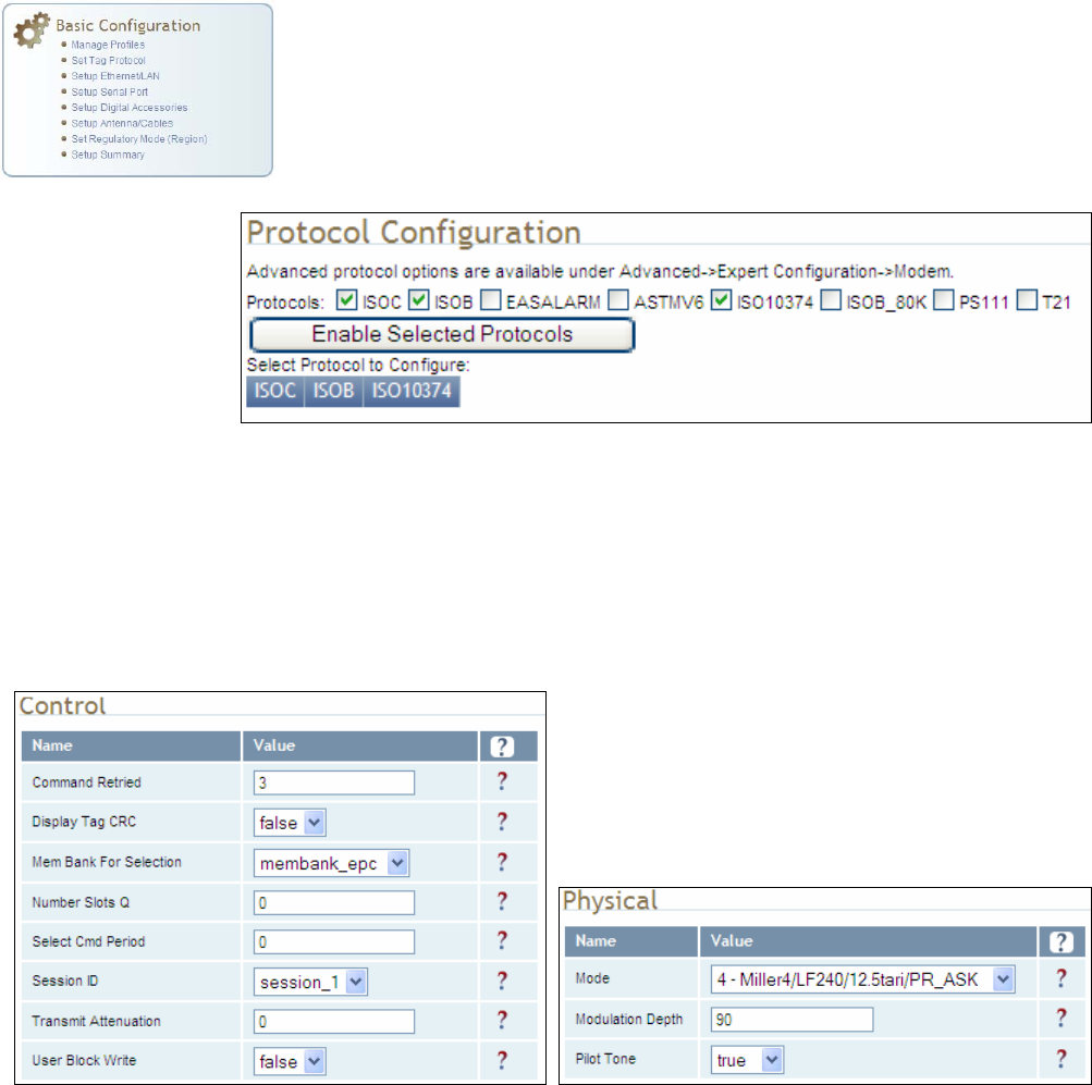
6.1.3. Set Tag Protocol
This Set Tag Protocol page consists of two forms. The first form (top) allows
you to select which type of tags the reader will acquire or the type of
protocol(s) to utilize on the air interface.
Select the check box for the protocol(s) to enable and then press Enable
Selected Protocols to activate the protocol.
Click on a specific protocol to view the lower form. This form allows you to
configure various protocol level parameters. The protocol level parameters
are divided into two categories: control and physical. Control parameters
configure the protocol control. Physical parameters configure the physical
air interface for the protocol.
For detailed information on each of the Control and Physical parameters,
refer to Chapter 15 – Modem Namespace of the IDentity 6204 Protocol
Reference Guide. Parameter descriptions are provided in the
modem.protocol.isoc.control and
modem.protocol.isoc.physical configuration variable sections.
1 2 3 4 5 6 7 8 9 Reader Configuration Tool
44 IDentity 6204 User’s Guide
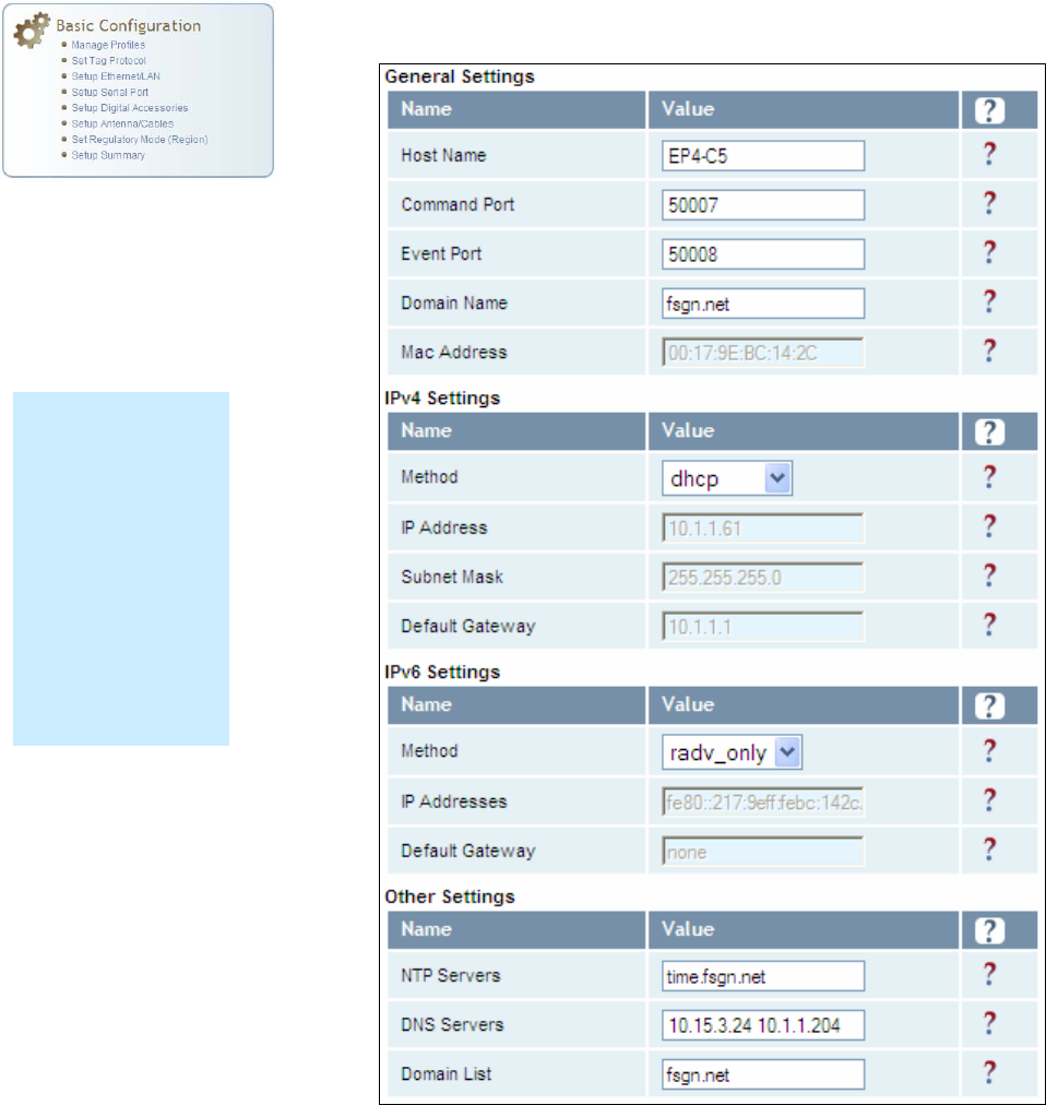
6.1.4. Setup Ethernet/LAN
The Setup Ethernet/LAN page allows you to configure the network interface
of the reader.
NOTE:
Always record the
IP, Mac, subnet,
and default
gateway addresses
for your readers
and keep this data
in a safe location.
You can use this
data to reconfigure
the network in the
event of application
failure or data loss.
1 2 3 4 5 6 7 8 9 Reader Configuration Tool
IDentity 6204 User’s Guide 45
General Settings allow you to specify the host and domain name of the
reader. The Command and Event Ports are also shown. You can also select
your domain name in this window.
IPv4/IPv6 Settings allow you to configure the reader’s IP address. If the
reader is to automatically acquire its IP address, subnet mask and default
gateway from a DHCP server, select Enable DHCP. To manually specify this
information, deselect Enable DHCP and fill in the desired IP address,
subnet mask and default gateway.
Other Settings allow you to configure the NTP servers the reader can
contact to obtain the current time, DNS servers the reader can contact for
domain name resolution, and the Domain list to resolve names to IP
addresses.
Enter all the required information and press Submit.
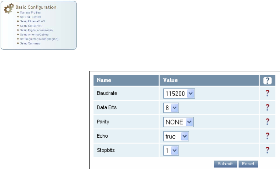
6.1.5. Setup Serial Port
The Setup Serial Port function allows you to configure the serial port
parameters. These parameters include:
h Baud rate
h Data bits
h Parity
h Echo
h Stop bits
Use the pull-down menus to select a value and press Submit to update the
reader.
1 2 3 4 5 6 7 8 9 Reader Configuration Tool
46 IDentity 6204 User’s Guide
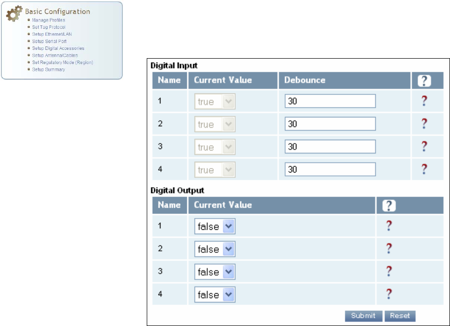
6.1.6. Setup Digital Accessories
The Setup Digital Accessories function allows you to configure the Digital
Inputs and Outputs on the reader.
Digital Input
The status of the four digital input values (1–4) can be seen in this window.
The Current Value is not configurable and is shown as true or false. The
Debounce value can be set and is in milliseconds.
Digital Output
The output value for each digital output can be set to true or false. Press
the Submit button to send the appropriate commands to the reader to
update the digital inputs and outputs.
Refer to the IDentity 6204 Protocol Reference Guide for more information
on configuring the digital inputs and outputs.
1 2 3 4 5 6 7 8 9 Reader Configuration Tool
IDentity 6204 User’s Guide 47
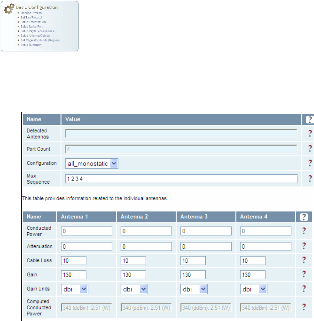
6.1.7. Setup Antenna/Cables
This page allows you to configure the reader’s antenna multiplexer
sequence as well as conducted power. For detailed descriptions of each of
the antenna and cable variables, refer to Antenna Configuration in Chapter
4 – Reader Behavior of the IDentity 6204 Protocol Reference Guide.
To configure an antenna, enter the antenna number in the Mux Sequence
field. The individual antenna Conducted Power fields will be activated in
the lower window. The current values will be displayed. Only those antennas
listed in the Mux Sequence will be shown. Also, you must set Conducted
Power to 0 in order to set or change the Attenuation, Cable Loss, or Gain.
To change, enter the appropriate values for each antenna parameter and
press the Submit button to update the antenna and cable configuration.
Select the next antenna and repeat.
1 2 3 4 5 6 7 8 9 Reader Configuration Tool
48 IDentity 6204 User’s Guide
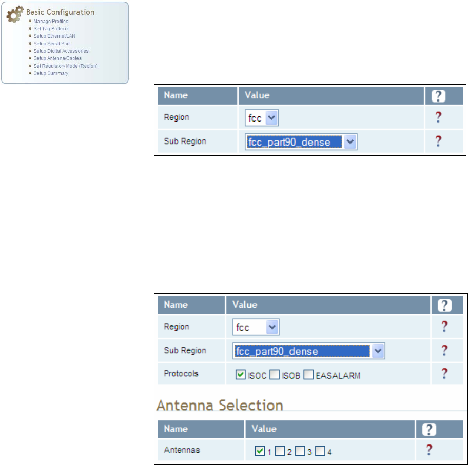
6.1.8. Set Regulatory Mode (Region)
This page allows the user to configure the reader to meet the regulatory
requirements for the geographic region where the reader is deployed. The
sub-region sets the secondary regulatory mode for the geographic region
where the reader is deployed.
For detailed information on each of these parameters, refer to the IDentity
6204 Protocol Reference Guide. Descriptions are provided in the
setup.region and setup.sub_region configuration variable
sections.
6.1.9. Setup Summary
This page allows you to quickly setup the basic operational parameters of
the reader.
1 2 3 4 5 6 7 8 9 Reader Configuration Tool
IDentity 6204 User’s Guide 49
6.2. Advanced Functions
With the Advanced Functions you can perform the following:
h Firmware Management
h Import/Export Configuration
h Command Line operations
h Expert Configuration
h User Application Management
h Change Operating Mode
h Restart
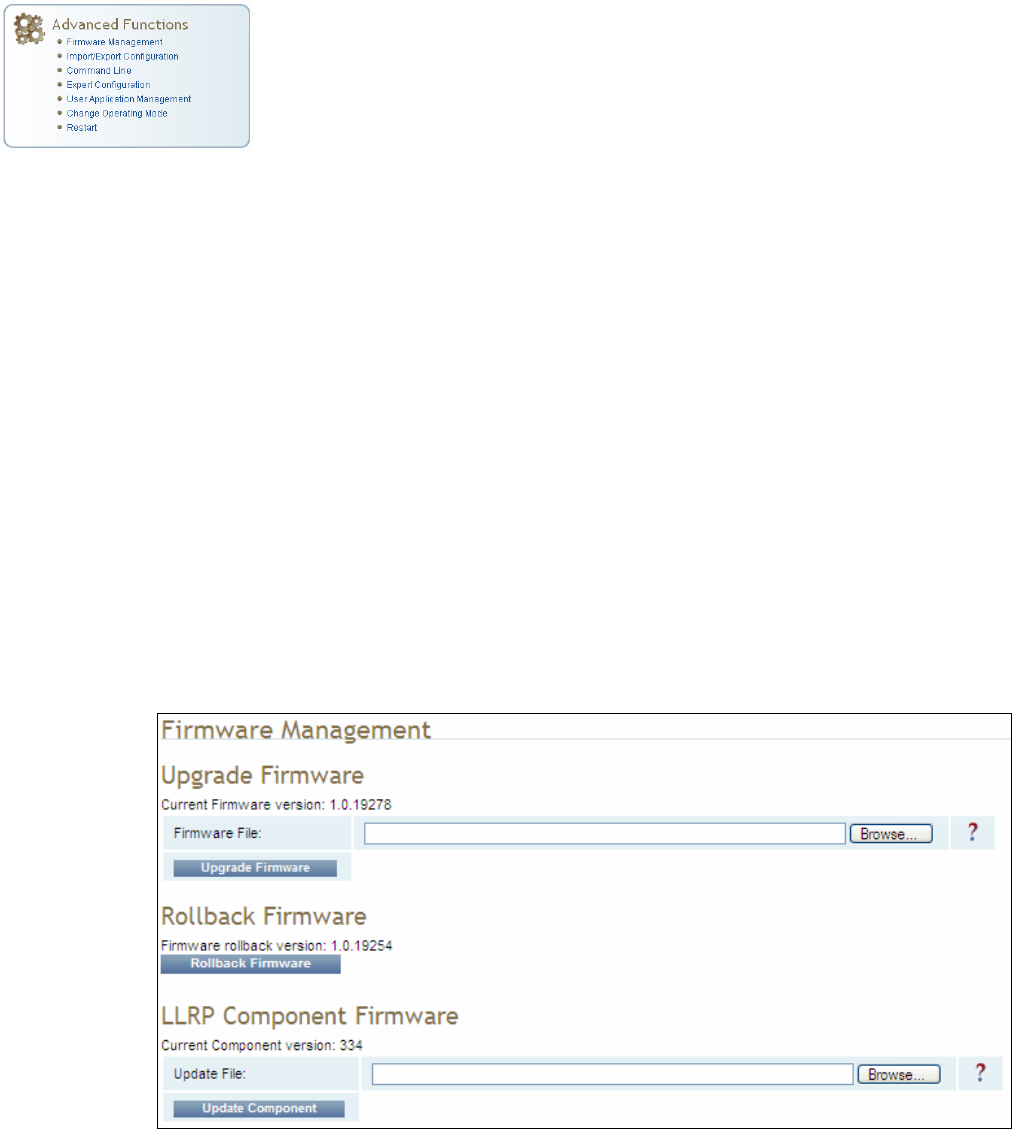
6.2.1. Firmware Management
This page allows you to read the current firmware version, upgrade the
reader firmware files, or rollback to the previous firmware version.
To upgrade reader firmware, enter the name of the Sirit provided firmware
file in the Firmware File field. Use the Browse button to help locate the file.
Once the filename is entered, press Upgrade Firmware. Note that this
function also upgrades the LLRP Component firmware.
To only upgrade the LLRP firmware, enter the name of the Sirit provided
LLRP firmware file in the Update File field. Use the Browse button to help
locate the file. Once the filename is entered, press Update Component.
The Rollback Firmware button will roll back the firmware to the previous
version. This function does not rollback the LLRP component firmware. You
will need to update the component with a previous version.
1 2 3 4 5 6 7 8 9 Reader Configuration Tool
50 IDentity 6204 User’s Guide
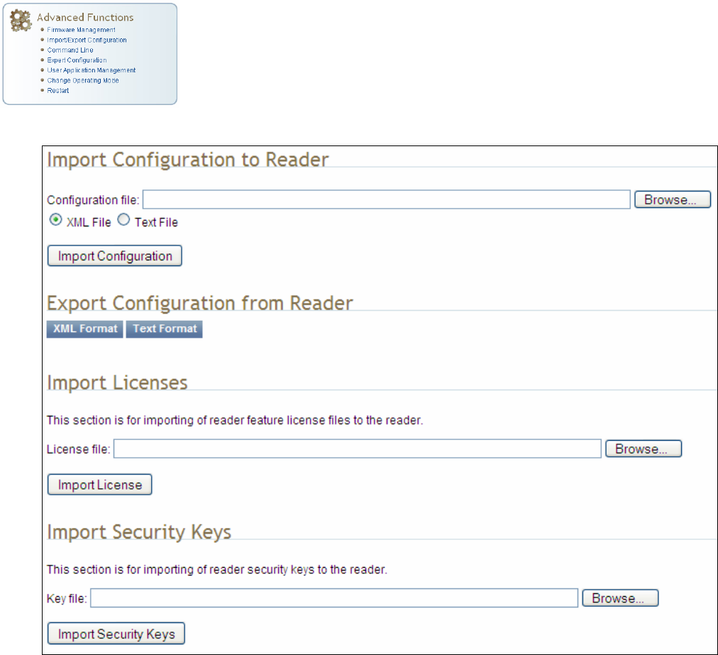
6.2.2. Import/Export Configuration
This page allows you to transfer a reader configuration to or from your host
computer. This is useful for configuring a reader to a known state.
1 2 3 4 5 6 7 8 9 Reader Configuration Tool
IDentity 6204 User’s Guide 51
Import Configuration to Reader
Enter the name of a saved configuration file in the Configuration file field.
Select the XML File option and press the Transfer Configuration to Reader
button to send the profile to the reader.
Export Configuration from Reader
This function is used to export the current reader settings for later
uploading. Press the XML Format button to view the XML file in the browser.
Save this file to your computer if you wish retain it for future.
If you wish to view the current configuration parameters for a reader, press
Text Format button.
Import Licenses
This function is used to import a feature license file. Navigate to the license
file and press Import License to load the file into the reader.
Import Security Keys
This function is used to import reader security keys to the reader. Navigate
to the key file and press Import Security Keys to load the file into the
reader.
1 2 3 4 5 6 7 8 9 Reader Configuration Tool
52 IDentity 6204 User’s Guide
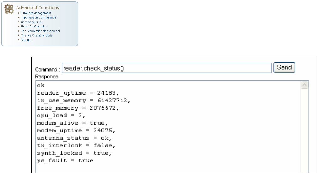
6.2.3. Command Line
This page allows you to directly enter reader commands from your web
browser.To directly enter commands from the Command Line Interface
(CLI), refer to the IDentity 6204 Protocol Reference Guide.
1 2 3 4 5 6 7 8 9 Reader Configuration Tool
IDentity 6204 User’s Guide 53
6.3. Expert Configuration
The Expert Configuration functions allow you to configure low-level functions
within the reader. These functions should only accessed by expert users.
Expert configurations include:
h Setup
h Tag
h Version
h Information
h Communication
h Antennas
h Digital I/O
h Modem
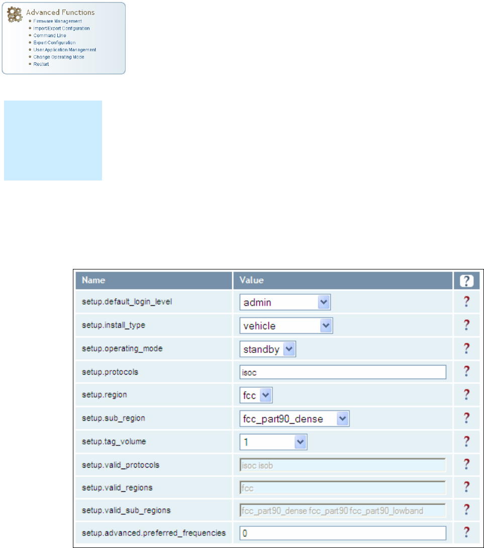
6.3.1. Expert Configuration – Setup
This page allows you to set the basic operating parameters of the reader
including region, sub region, mode, and active protocols. You can also view
the valid protocols and regions.
NOTE
For details on
reader variables,
refer to the IDentity
6204 Protocol
Reference Guide.
1 2 3 4 5 6 7 8 9 Reader Configuration Tool
54 IDentity 6204 User’s Guide
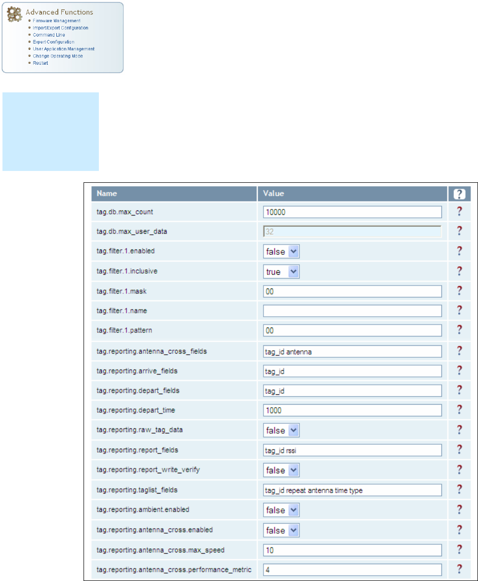
6.3.2. Expert Configuration – Tag
This page allows you to configure how the reader reports tags.
The IDentity 6204 supports the ability to filter tags or eliminate tags from
being reported based on the conditions specified in the filter configuration
variables. The reader supports eight filters and each filter is specified by the
following configuration variables:
h enabled – Enables or disables the filter.
h inclusive – Indicates to either include tags that match (Inclusive) or
include tags that do not match (Exclusive) the tag filter.
h mask – Mask (as an array of hex bytes) for the tag filter.
h name – Name given to the tag filter
h pattern – Pattern (as an array of hex bytes) for the tag filter
The following figure shows a small sample of the available variables.
NOTE
For details on tag
variables, refer to
the IDentity 6204
Protocol Reference
Guide.
1 2 3 4 5 6 7 8 9 Reader Configuration Tool
IDentity 6204 User’s Guide 55
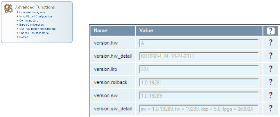
6.3.3. Expert Configuration – Version
This page displays the version of reader hardware and reader software
within the reader. The version numbers are read-only and will be needed if
you contact Sirit for technical support.
1 2 3 4 5 6 7 8 9 Reader Configuration Tool
56 IDentity 6204 User’s Guide
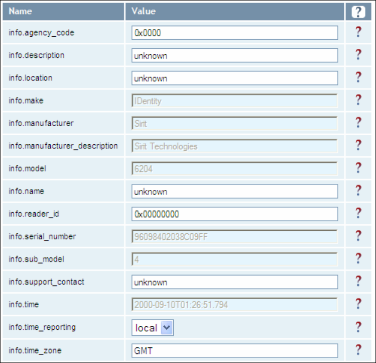
6.3.4. Expert Configuration – Information
This page allows you to customize the reader’s identity. You can assign
each reader a name, description, location, and zone. You can also set how
the reader reports timestamps.
1 2 3 4 5 6 7 8 9 Reader Configuration Tool
IDentity 6204 User’s Guide 57
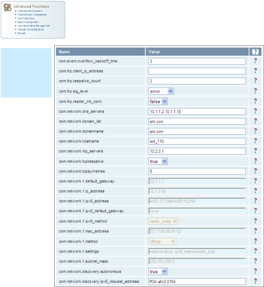
6.3.5. Expert Configuration – Communication
This page allows you to customize the reader’s communication parameters.
Refer to the Setup Ethernet/LAN and Setup Serial Port sections for
additional information.
The following figure shows a portion of communication parameters
available on the reader.
NOTE
For details on
communication
parameters, refer
to the IDentity
6204 Protocol
Reference Guide.
1 2 3 4 5 6 7 8 9 Reader Configuration Tool
58 IDentity 6204 User’s Guide
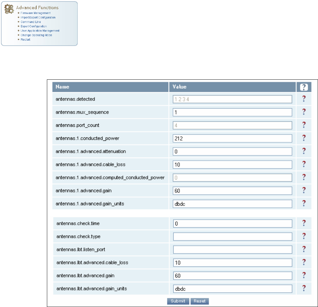
6.3.6. Expert Configuration – Antennas
This page allows you to configure the properties of the reader’s antenna
configuration. For detailed description of each of the antenna and cable
variables, refer to the Antenna Configuration section in Chapter 4 – Reader
Behavior of the IDentity 6204 Protocol Reference Guide.
Enter the appropriate values for each antenna parameter and press the
Submit button to update the antenna and cable configuration.
The following figure shows only a small sample of the available antenna
configuration variables.
1 2 3 4 5 6 7 8 9 Reader Configuration Tool
IDentity 6204 User’s Guide 59
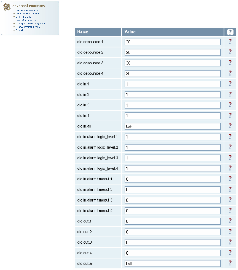
6.3.7. Expert Configuration – Digital I/O
This page allows you to configure the digital inputs and output behavior. You
can set the digital input debounce time (in milliseconds), as well as the
input and output pin values. Refer to the IDentity 6204 Protocol Reference
Guide for detailed information on each of these variables.
1 2 3 4 5 6 7 8 9 Reader Configuration Tool
60 IDentity 6204 User’s Guide
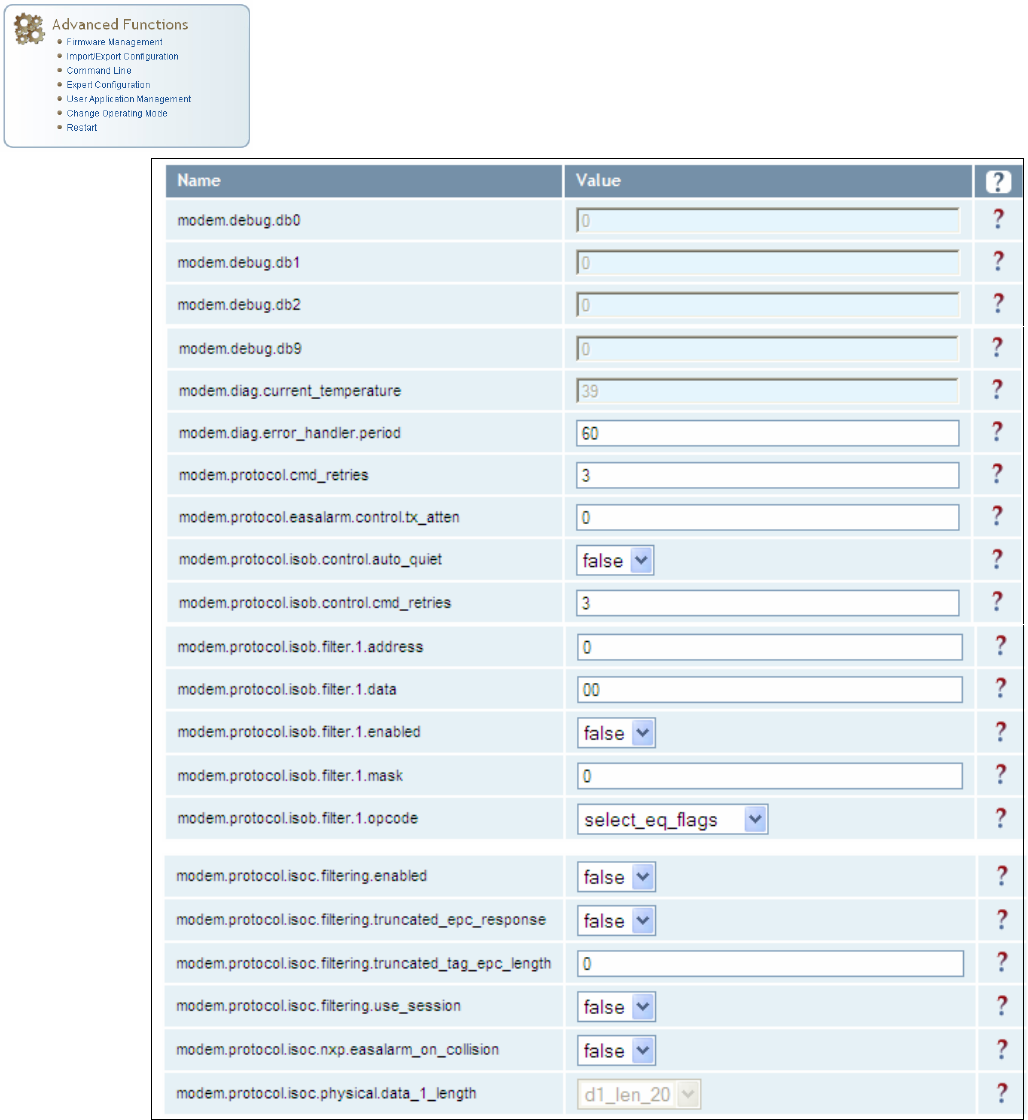
6.3.8. Expert Configuration – Modem
This page allows you to set the reader’s modem control variables. These
variables control functions such as EPC link, modulation depth, return link
frequency, and others. Refer to the IDentity 6204 Protocol Reference Guide
for detailed information on each of these variables. The following figure
shows only a small sample of the available modem configuration variables.
1 2 3 4 5 6 7 8 9 Reader Configuration Tool
IDentity 6204 User’s Guide 61
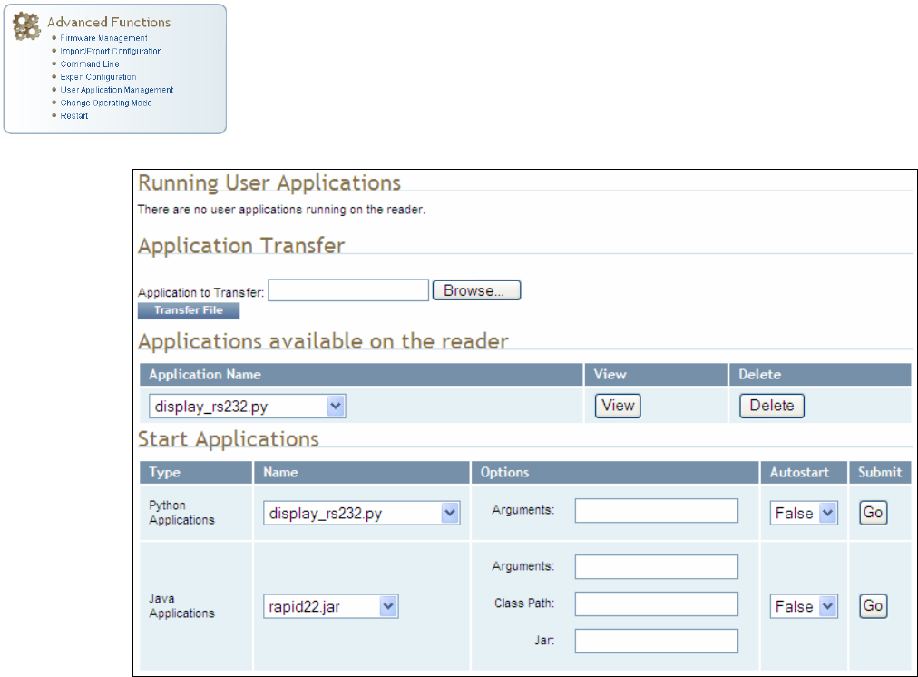
6.4. User Application Management
This page lists any user applications currently available on the reader and if
any applications are running. This page also allows you to upload
applications to the reader.
h Running User Applications – Lists any user applications currently
running on the reader. The application name, process ID, configuration,
and status are provided. Controls are provided to view the application
file and stop the application.
h Application Transfer – This function allows you to load custom user
applications onto the reader.
h Applications available on the reader – This function allows you to view a
list of all user applications stored on the reader. Controls are provided
to view the application and delete it from the reader.
h Start Applications – This function allows you to start Python and Java
applications.
1 2 3 4 5 6 7 8 9 Reader Configuration Tool
62 IDentity 6204 User’s Guide
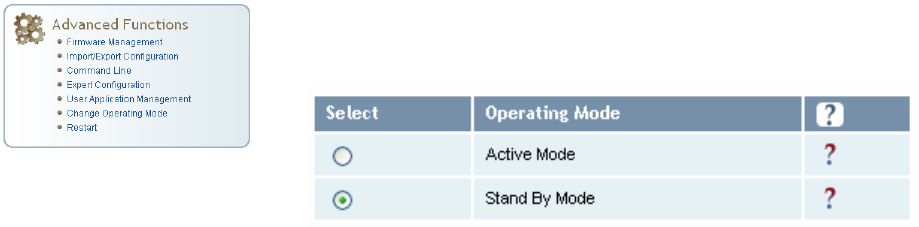
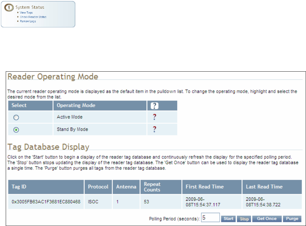
6.5. Change Operating Mode
This page allows you to configure the operational mode of the reader.
The reader supports the following operational modes:
h Active Mode - Reader is continuously attempting to singulate tags and
automatically reports any singulated tag via an asynchronous event
notification on the event channel.
h Stand By Mode - Reader is not transmitting any energy, unless
processing a tag related command. The RF transmitter is enabled at the
beginning of the command processing, any protocol operations required
for the command are performed, and then the RF transmitter is turned
back off.
1 2 3 4 5 6 7 8 9 Reader Configuration Tool
IDentity 6204 User’s Guide 63
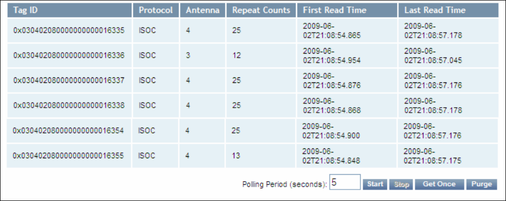
6.6. View Tags
All tags read by the reader are stored in a database on the reader. This
page allows you to view the tags in the database as well as change the
current Operating Mode (Active or Stand By).
Press Start to begin displaying the tag database. This page is automatically
refreshed every five seconds. Press Get Once to update the database one
time (refresh is off). Press Purge to purge all tags from the database.
1 2 3 4 5 6 7 8 9 Reader Configuration Tool
64 IDentity 6204 User’s Guide
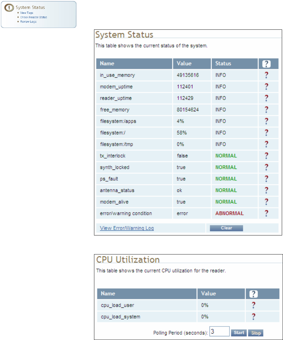
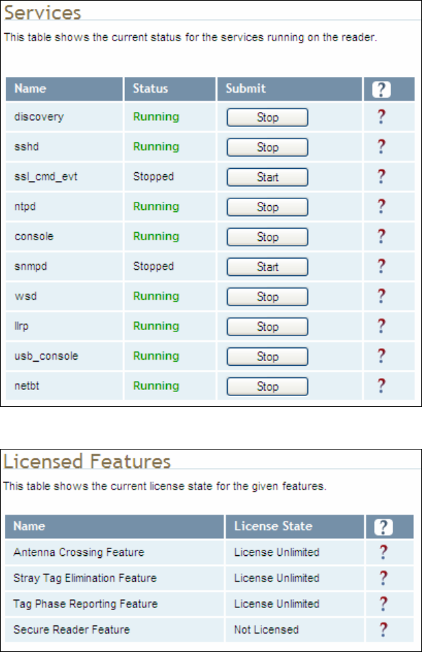
6.7. Check Reader Status
This page allows you to view the reader/system status, CPU utilization,
services, and licensed features. This information can be used by Sirit
Technical Support to verify reader operation.
1 2 3 4 5 6 7 8 9 Reader Configuration Tool
IDentity 6204 User’s Guide 65
1 2 3 4 5 6 7 8 9 Reader Configuration Tool
66 IDentity 6204 User’s Guide
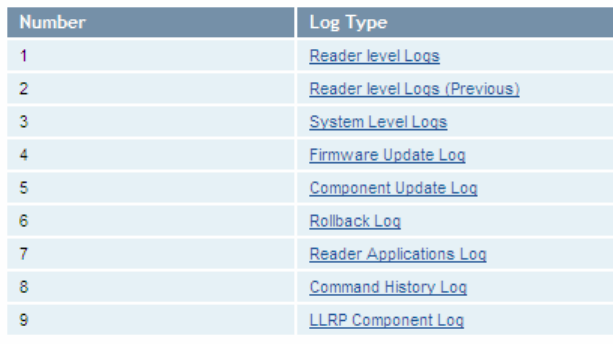
6.8. Review Logs
This page allows you to view the reader logs. These logs can be used by Sirit
Technical Support to verify reader operation. The reader logs include:
h Reader level Logs – System level reader operation
h System Level Logs – Linux logs
h Firmware Update Log – Status of last firmware update
h Component Update Log – status of last component firmware update
h Rollback Log – Previous firmware
h Reader Applications Log – User application logs
h Command History Log – Recent commands sent to the reader.
h LLRP Component Log – LLRP service
h

1 2 3 4 5 6 7 8 9 Configuring Digital I/Os
IDentity 6204 User’s Guide 67
7 Configuring Digital Inputs and Outputs
7.1. Digital Inputs
The digital inputs (DIN1 – DIN4) can be used as general purpose inputs or
to trigger the reader for tag reading. Unused or open digital inputs are
floating inside the reader.
To activate the input, pull it low (0 Vdc) with an external device or
connection to ground that can sink 2.5 mA. No voltage higher than +24 Vdc
or lower than 0 Vdc should ever be connected to the input. See Figure 5 for
an example of a typical motion sensor installed as a tag read trigger device.
7.2. Digital Outputs
The digital outputs (DOUT1 – DOUT4) can be used as general purpose
outputs, to indicate tag reading activity, or to indicate the reader is
transmitting (RF On). Digital outputs can be pulled high.
No voltage higher than +40 Vdc or lower than 0 Vdc should ever be
connected to a digital output. The reader activates the output by pulling it
low (0 Vdc) and can sink current such that power dissipation is ≤ 1W.
7.3. Low Latency Digital Input/Output Operation
The IDentity 6204 is equipped with low-latency digital inputs and outputs.
The inputs (3 and 4) can be used by the modem to trigger low-latency
events. Two commands control these inputs as follows:
modem.dio.in.X.positive_level = Y -- if X goes high, it triggers Y
modem.dio.in.X.negative_level = Y -- if X goes low, it triggers Y
where Y can be:
NOOP (default)
ACTIVE_MODE
STANDBY_MODE
TOGGLE_MODE
ONE_ROUND (performs one inventory round, nonblock)
RUN_SCRIPT (runs series of modem commands, see the following)
Digital I/O Module
An optional Digital
I/O Module is
available for the
IDentity 6204.
Refer to Appendix A
for more
1 2 3 4 5 6 7 8 9 Configuring Digital I/Os
68 IDentity 6204 User’s Guide
Any time the RUN_SCRIPT operation is invoked, the reader will sequence
through a maximum of 10 modem commands as follows:
modem.dio.in.X.script.num_cmds = Q
modem.dio.in.X.script.cmd1 = Z
modem.dio.in.X.script.cmd2 = Z
modem.dio.in.X.script.cmd3 = Z
.
.
.
modem.dio.in.X.script.cmd10 = Z
where:
Q is the number of commands. Q can be 0 to 10 (maximum 10
modem commands).
Z can be any modem command
An event event.response.modem_dio_scripts dio_in=*,
cmdnum=*, resp=*** is generated after each modem command.
Digital outputs 3 and 4 can be driven by modem after setting the following:
dio.control.X = modem
Actions that triggered the output can be defined by:
modem.dio.out.X.op = Y
where Y can be:
NOOP (default)
END_OF_ROUND (generates a pulse at end of each inventory round)
ACTIVE_MODE (triggers high in active mode)
SCRIPT_RUNNING (triggers high when digital input io triggered
script is running)
ANTENNA_FAILURE (triggers high in antenna failure state)
ERROR (generates a pulse when an error occurs)
WARNING (generates a pulse when an warning occurs)
All output (level/pulse) polarity is defined by:
modem.dio.out.X.polarity = Z
where Z can be:
POSITIVE (default)
NEGATIVE
All pulse width (in µSec) is defined by:
modem.dio.out.X.pulse_width –(default 100 µSec)
1 2 3 4 5 6 7 8 9 Configuring Digital I/Os
IDentity 6204 User’s Guide 69
Example (Input)
The following example triggers a series of modem commands, when DIO
input 4 goes high.
modem.dio.in.4.positive_level = RUN_SCRIPT
modem.dio.in.4.script.num_cmds = 3
modem.dio.in.4.script.cmd1 = "modem.antennas.perform_check()"
modem.dio.in.4.script.cmd2 = "modem.diag.current_temperature"
modem.dio.in.4.script.cmd3 = "modem.stats.tag_read"
Example (Output)
In the following example, DIO output 3 will trigger low when the reader is in
active mode.
dio.control.3 = modem
modem.dio.out.3.op = ACTIVE_MODE
modem.dio.out.3.polarity = NEGATIVE
7.4. Digital I/O Monitoring and Control Scripts
Several digital I/O monitoring and control scripts are provided with the
reader to allow you to monitor the digital I/Os and take specific actions.
These Python application scripts can be used as is or modified to suit your
particular application. For detailed information on loading Python scripts,
refer to Chapter 5 – Embedded Reader Applications of the IDentity 6204
Protocol Reference Guide.
7.4.1. scan_trigger.py
This routine monitors the state of the digital input pin specified as the input
parameter. If the state of the pin is low, the operating mode is set to standby. If
the I/O pin state changes to high, the operating mode is set to active.
Inputs: <pin> – (optional) Input pin number (1–4). Default is digital in 1.
<trigger logic level> –(optional) 0 or 1. Default is trigger on 1.
Examples:
scan_trigger.py Monitors digital input pin 1
scan_trigger.py 1 Monitors digital input pin 1
scan_trigger.py 4 Monitors digital input pin 4
scan_trigger.py 3 0 Monitors digital input pin 3, trigger on 0
1 2 3 4 5 6 7 8 9 Configuring Digital I/Os
70 IDentity 6204 User’s Guide
7.4.2. scan_trigger_timer.py
This routine monitors the I/O pin. When the pen goes high, the timer is started
and the operating mode is set to active. While the timer is running, I/O pin state
changes are ignored. When the timer expires, the operating mode is set to
standby. The minimum value for the timer is 10 milliseconds (ms).
Inputs: <pin> – (optional) Output pin number (1–4). Default is output 1.
<time> – (optional) Time, in ms for timer to run. Default is 1000 ms.
<trigger logic level> –(optional) 0 or 1. Default is trigger on 1.
Examples:
scan_trigger_timer.py Monitors input 1, timer 1000 ms,
trigger on 1
scan_trigger_timer.py 2 Monitors input 2, timer 1000 ms,
trigger on 1
scan_trigger_timer.py 4 2000 Monitors input 4, timer 2000 ms,
trigger on 1
scan_trigger_timer.py 3 4000 0 Monitors digital input 3, timer 4000 ms,
trigger on 0
7.4.3. signal_read.py
This routine will turn on a digital output if a tag is successfully read. The
optional output pin number can be specified on the command line. If not
specified, output pin 1 is used. The output pin will remain high for n ms, where
n is either the default of 1000 ms, or the value supplied on the command line.
Minimum value for n is 10 ms.
Inputs: <pin> – (optional) Output pin number (1–4). Default is output 1.
<time> – (optional) Time, in ms, to keep the output high. Default is
1000 ms (1 sec).
<logic level> – (optional) Logic level for digital out On. 0 or 1. Default
is 1 (On).
Examples:
signal_read.py Turns on output 1 for 1000 ms on tag reads
signal_read.py 2 Turns on output 2 for 1000 ms on tag reads
signal_read.py 1 5000 Turns on output 1 for 5000 ms on tag reads
signal_read.py 1 500 Turns on output 1 for 500 ms on tag reads
signal_read.py 1 800 0 Turns on digital output 1,logic level 0, for
800 ms on tag reads
1 2 3 4 5 6 7 8 9 Configuring Digital I/Os
IDentity 6204 User’s Guide 71
7.4.4. signal_read_crc_error.py
This routine will turn on a digital output if a tag read CRC error is detected. The
output pin number can be specified on the command line. If not specified,
output pin 1 is used. The output pin will remain high for n ms, where n is either
the default of 1000 ms or the value supplied on the command line. Minimum
value for n is 10 ms.
Inputs: <pin> – (optional) Output pin number (1–4). Default is output 1.
<time> – (optional) Time, in ms, to keep the output high. Default is
1000 ms.
<logic level> – (optional) Logic level for digital out On. 0 or 1.
Default is 1 (On).
Examples:
signal_read_crc_error.py Turns on output 1 (logic level 1=on),
for 1000 ms on tag read CRC error.
signal_read_crc_error.py 2 Turns on output 2 (logic level 1=on),
for 1000 ms on tag read CRC error.
signal_read_crc_error.py 1 5000 Turns on output 1 (logic level
1=on), for 5000 ms on tag read
CRC error.
signal_read_crc_error.py 1 500 Turns on output 1 (logic level
1=on) for 500 ms on tag read CRC
error.
signal_read_crc_error.py 1 800 0 Turns on output 1 (logic level
0=on), for 800 ms on tag CRC
error.
7.4.5. rf_mon.py
This routine will monitor the state of the transmitter. If the transmitter is on, it
sets the appropriate output pin high. If low, it sets the output pin low.
Inputs: <pin> – (optional) Output pin number (1–4). Default is output 1.
<logic level> – (optional) Logic level for digital out On. 0 or 1.
Default is 1 (On).
Examples:
rf_mon.py Monitors RF status, set/clear output 1 on change, logic
level 0 for on
rf_mon.py 1 Monitors RF status, set/clear output 1 on change, logic
level 0 for on
rf_mon.py 2 Monitors RF status, set/clear output 2 on change, logic
level 0 for on
rf_mon.py 3 0 Monitors RF status, set/clear output 3 on change, logic
level 1 for on
1 2 3 4 5 6 7 8 9 Configuring Digital I/Os
72 IDentity 6204 User’s Guide
7.5. Digital Input Alarm Generation
The IDentity 6204 can be configured to generate an alarm when a digital
input is disconnected or sensor failure is detected. The alarm is triggered
when the signal level on the digital input stays in the specified state longer
than the specified alarm timeout. This behavior can be configured
independently for each digital input.
The configuration variable dio.in.alarm.logic_level.<N> (where <N> is
1,2,3,4) sets whether the alarm is coupled to a input logic level of 0 (low) or
1 (high).
The configuration variable dio.in.alarm.timeout.<N> (where <N> is 1,2,3,4)
sets the amount of time, in seconds, to wait for a signal state change. A
value of 0 (default) disables alarm generation.
The digital input logic level is used along with the corresponding digital input
pin timeout value to determine if an alarm (in the form of an event) should
be generated. If a timeout value is set, the input pin is monitored. If the
input pin value does not change during the timeout period AND the input
pin value matches the alarm logic level, the event
event.dio.in.alarm.timeout.n (where n is the pin number) is generated. This
alarm event generation can be helpful in alerting to the loss of digital inputs
to the reader.
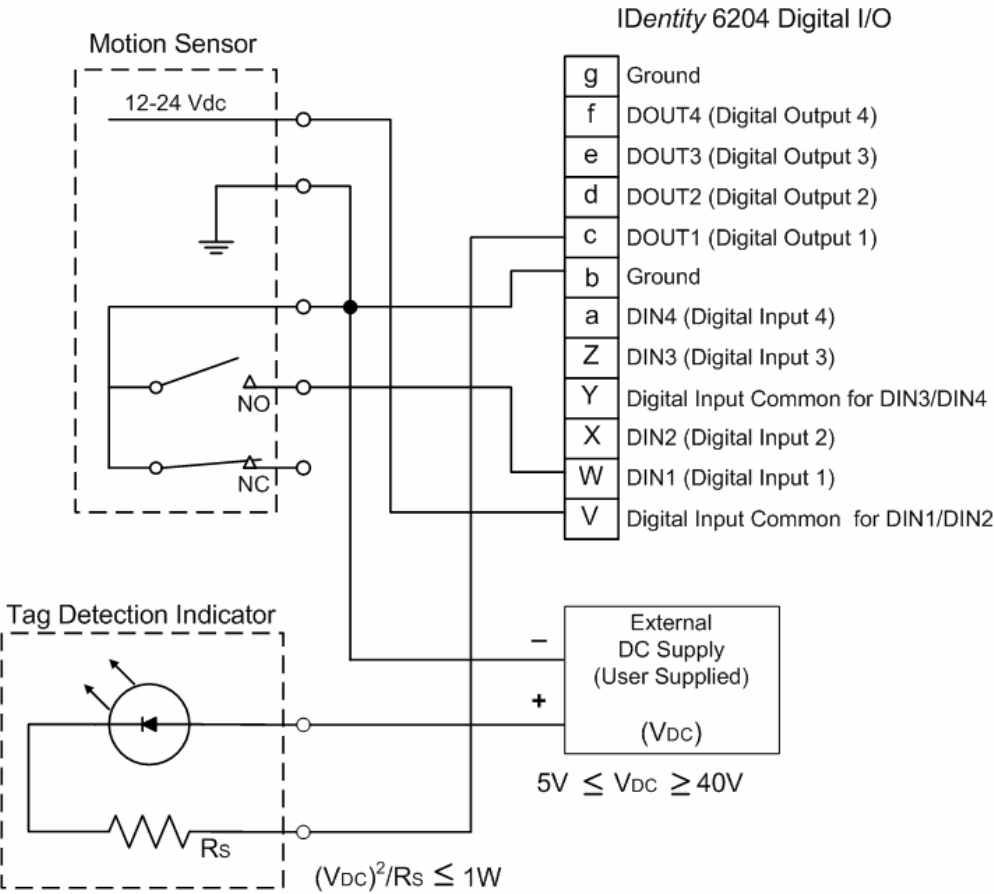
1 2 3 4 5 6 7 8 9 Configuring Digital I/Os
IDentity 6204 User’s Guide 73
7.6. Digital I/O Hardware Connection
Figure 5 shows a typical sensor/indicator connection to the digital I/Os.
Figure 5 Example Motion Detector and Indicator connected to the Digital I/O

1 2 3 4 5 6 7 8 9 Specifications
74 IDentity 6204 User’s Guide
8 Specifications
8.1.1. Reader Specifications
Frequency 902 – 928 MHz
RF Power 10 mW – 2W conducted (33 dBm)
Power Consumption 10W (typical while idle)
18W (typical at 1W conducted output power)
22W (maximum at 2W conducted output power)
Connections RS-232, Digital I/O, Ethernet LAN
Input Voltage 24 Vdc
Input Current 1.5A maximum at 24 Vdc
Active Mode DC Current Draw vs Transmitted Power
0.4
0.5
0.6
0.7
0.8
0.9
1
10 15 20 25 30 35
Transmitted Power (dBm)
DC Current draw (A)
+60 degC
+25 degC
-20 degC
Figure 6 Typical Power Consumption versus Conducted Output Power at 910 MHz

1 2 3 4 5 6 7 8 9 Specifications
IDentity 6204 User’s Guide 75
8.1.2. Environmental Specifications
Operating Temperature -40 °F to 131 °F (-40 °C to 55 °C)
Storage Temperature -40 °F to 185 °F (-40 °C to 85 °C)
Maximum Shock 1 foot (0.3 meter) drop to any corner
Relative Humidity 100%, condensing
Int’l Protection Rating IP67
Dimensions 16.5 x 12.2 x 3.4 in (419 x 310 x 86 mm)
Weight 11.0 lbs (5 kgs)
8.1.3. AC/DC Power Adapter Specifications
Model Lambda DSP100-24
Input Voltage 90 – 264 Vac,
Input Frequency 47 to 63 Hz
Power 100.8 W
Holdup Time 10 ms (115 Vac)
Output Voltage 24 VDC
Output Current 4.2 A
8.1.4. RS-232 Specifications
Baud rate 1200 - 115200 (Default = 115200)
Parity None
Data bits 8
Stop bits 1
Signals Refer to Section 0 for cable pin out.
8.1.5. Digital Input/Output Specifications
Input 5 to 24 Vdc, 1 to 5 mA, Optically Isolated
Output Open Collector (3 to 40 V, 100 mA Max)
Signals Refer to Section 0 for cable pin out.
8.1.6. Ethernet LAN Specifications
Ethernet 10/100 BaseT
Signals Refer to Section 0 for cable pin out.

1 2 3 4 5 6 7 8 9 Specifications
76 IDentity 6204 User’s Guide
8.1.7. IDentity 6204 Antenna Specifications
Please refer to the Sirit Antenna Application Guide for detailed
specifications and application information for IDentity 6204 antennas.
Part Number ANTENNA-021 ANTENNA-024
Frequency range 902–928 MHz 902–928 MHz
Antenna type Patch Multi-element Patch
Impedance 50 Ω, nominal 50 Ω, nominal
Gain 13 dBi 15 dBi
Beam width (-3 dB) 36°, nominal 30°, nominal
Polarization Linear Linear
F/B ratio -20 dB, typical -36 dB, typical
Side lobes level -14 dB, typical -18 dB, typical
Power input 37 dBm (5 W) 37 dBm (5 W)
Return loss -12 dB, minimum -12 dB, minimum
Connector type N type Female (Jack) N type Female (Jack)

1 2 3 4 5 6 7 8 9 Specifications
IDentity 6204 User’s Guide 77
Site License –
Customer Disclaimer Customer (end user) acknowledges that a site license is required for each reader
system location. It is the customer’s responsibility to file for the site license and
submit the appropriate filing payment. Sirit can assist with the completion of
forms. United States filings require completion and submission of FCC Form 601
with Schedule D and H. Canadian filings require completion and submission of
Industry Canada Forms IC2365BB and IC2430BB.
Licence d'Etat-client Avertissement
Client (utilisateur final) reconnaît que le site d'une licence est requise pour
chaque lecteur emplacement du système. Il incombe au client de déposer pour la
licence d'exploitation et soumettre le paiement du dépôt approprié. Sirit peut
aider à la réalisation de formes. Unis dépôts États exigent l'achèvement et la
soumission du formulaire FCC 601 à l'annexe D et H. dépôts canadiennes exigent
l'achèvement et la soumission de Industrie Canada Formulaires IC2365BB et
IC2430BB
Caution: This equipment complies with FCC Part 90 and Industry Canada.RSS-137 rules.
This device complies with FCC Part 15 and Industry Canada license exempt RSS
standard(s). Operation is subject to the following two conditions: (1) this device
may not cause interference, and (2) this device must accept any interference,
including interference that may cause undesired operation of the device.
Cet appareil est conforme à FCC Partie15 de Industrie Canada RSS standard
exempts de licence (s). Son utilisation est soumise à Les deux conditions
suivantes: (1) cet appareil ne peut pas provoquer d’interférences et (2) cet
appareil doit accepter Toute interférence, y compris les interférences qui peuvent
causer un mauvais fonctionnement du dispositif.
Any changes or modifications not expressly approved by Sirit could void the user’s
authority to operate the equipment.
The professional installer will need to calculate and verify the reader’s power
output allowable based on the antenna (gain) used and cabling (loss) effects.
This value will be used in the user’s submission of their site license application.
The maximum antenna gain plus cable effects for a given output power can be
calculated by:
44.8 dBm (ERP) - Pout
where Pout is the measured RF output power (dBm)
Reader output power is limited to a maximum of 2W under all conditions. When
operating at that power level, the maximum permissible antenna gain is 11.2dBd.

1 2 3 4 5 6 7 8 9 Specifications
78 IDentity 6204 User’s Guide
WARNING: FCC Radiation Exposure Statement. The antennas used for this transmitter
must be installed to provide a separation distance of at least 1 meter from all
persons and must not be co-located or operating in conjunction with any other
antenna or transmitter.
This device complies with Health Canada’s Safety Code The installer of this
device should ensure that RF radiation is not emitted in excess of the Health
Canada’s requirement. Information can be obtained at:
http://www.hc-sc.gc.ca/ewh-semt/pubs/radiation/radio_ guidelignes_direct-eng.php
Cet appareil est conforme avec Santé Canada Code de sécurité 6 . Le
programme d’installation de cet appareil doit s’assurer que les rayonnements
RF n’est pas émis au-delà de I’exigence de Santé Canada. Les informations
peuvent être obtenues:
http://www.hc-sc.gc.ca/ewhsemt/pubs/radiation/radio_ guide-lignes_direct-eng.php

1 2 3 4 5 6 7 8 9 Specifications
IDentity 6204 User’s Guide 79
8.1.8. Bulkhead Connector/Interface Cable Pinout
Pair Pin Color Pin Name Function
A Black Tx+ Ethernet 1
B Green Tx- Ethernet
C Black Rx+ Ethernet 2
D Orange Rx- Ethernet
E Blue VC2+ Ethernet 3
F Black VC2- Ethernet
G Black VC2+ Ethernet 4
H Brown VC2- Ethernet
J Black RS-232 TXD Serial Port 5
K Red RS-232 RXD Serial Port
L Black DTR (Connected to M-DSR) Serial Port 6
M White RS-232 GND Serial Port
N Black DSR (Connected to L-DTR) Serial Port 7
P Yellow RS-232 CTS Serial Port
R Red RS-232 RTS Serial Port 8
S White No Connect
T Red +24 VDC Power 9
U Green 24 VDC GND Ground
V Red DIN Ref 1 Digital Input Common 10
W Blue DIN1 Digital Input 1
X Red DIN2 Digital Input 2 11
Y Yellow DIN Ref 2 Digital Input Common
Z Red DIN3 Digital Input 3
12
a Brown DIN4 Digital Input 4
b Red GND Ground (Reader) 13
c Orange DOUT1 Digital Output 1
d Green DOUT2 Digital Output 2
14
e White DOUT3 Digital Output 3
f Green DOUT4 Digital Output 4
15
g Blue GND Ground (Reader)
h Yellow +24 VDC H. Power 16
j Green 24 VDC GND H. Ground
1 2 3 4 5 6 7 8 9
Safety Instructions
80 IDentity 6204 User’s Guide
9 Safety Instructions
9.1. Power Disconnect Device
The plug on the power supply cord is intended to be the power disconnect
device. As a result, the power source (socket or outlet) shall be located near
the equipment and shall be easily accessible.
9.2. RF Safety
WARNING: Part 90 Radiation Exposure Statement. The antennas used for this transmitter
must be installed to provide a separation distance of at least 1 meter from all
persons and must not be co-located or operating in conjunction with any other
antenna or transmitter.
Caution: The IDentity 6204 UHF Reader is equipped with four (4) RF ports. To prevent
reader damage, active RF ports must be properly terminated with a 50 ohm
load or a functional UHF antenna before power up. UHF Readers are factory
configured to operate on RF port 1. As a result, port 1 must be properly
terminated before initially powering on the reader. Before activating any
additional RF ports, they must also be properly terminated. Never power up
the reader unless the appropriate loads or antennas are connected. Always
power down the reader before removing an antenna or load from an RF port.
9.3. Electrostatic Discharge
ATTENTION IDentity 6204 antenna ports may be susceptible to damage from static
discharge or other high voltage. Use proper Electrostatic Discharge
(ESD) precautions to avoid static discharge when handling or making
connections to the IDentity 6204 reader antenna or communication
ports. Equipment failure can result if the antenna or communication
ports are subjected to ESD.
9.4. Regulatory Compliance
Caution: The IDentity 6204 is designed to meet the regulatory requirements in those
jurisdictions in which it is offered. Changes or modifications not expressly
approved by Sirit Inc for compliance could void the user's authority to operate
the equipment.

1 2 3 4 5 6 7 8 9 Appendix A – Error Handling
IDentity 6204 User’s Guide 81
A Error Handling
This appendix provides a listing of errors and warnings. Where applicable, a
corrective action has been provided. Errors and warnings are listed by
severity (critical, major, warning) and then alphabetically. If an issue does
not resolve itself after taking the recommended corrective action, contact
Sirit support.
A.1. Critical Errors
Critical errors are those errors that are likely to result in loss or severe
degradation of service. These errors must be addressed immediately.
Critical Error Event Description Corrective Action
MDM_ANTENNA_ FAILURE event.error.
antenna
Failed to set or change
antenna. Probably due to
un-terminated antenna
port.
Check condition of antennas,
connectors, and coax. Use
modem.antennas.perform_check() to
perform antenna check function to
determine if issue has been located.
MDM_CLOSED_LOOP_
POWER_CTL_FAIL
event.error.
radio
Internal RF power control
failed. May cause
inaccurate antenna power
output.
Perform reader reboot. If condition
persists, contact Sirit support.
MDM_OVERTEMP_ FAULT event.error.
environmental
High temperature
measured at modem
Determine cause of excessive reader
temperature and correct.
MDM_RC_CANT_SET_
FREQUENCY
event.error.
radio
Synthesizer problem tuning
to desired frequency.
Perform reader reboot. If condition
persists, contact Sirit support.
MDM_RC_NO_ ANTENNA event.error.
antenna
Failed to detect antenna.
Probably due to antenna
disconnected.
Check antenna connections, then
perform antenna check function.
MDM_SPI_NO_
RESPONSE
event.error.
communication
Modem has attempted to
communicate with a SPI
bus peripheral and
received no response.
Perform reader reboot. If condition
persists, contact Sirit support.
MDM_SYNTHESIZER_
LOCK_FAIL
event.error.
radio
Synthesizer can't lock to
desired frequency.
Perform reader reboot. If condition
persists, contact Sirit support.
MDM_TEMPERATURE_
SENSOR_FAIL
event.error.hw Temperature sensor
unable to detect
temperature.
Perform reader reboot. If condition
persists, contact Sirit support.
READER_INIT_FAILURE event.error.sw The main processor has
failed to successfully
complete the initialization
process.
Perform reader reboot. If condition
persists, contact Sirit support.
SEEPROM_UNABLE_
TO_WRITE
event.error.hw Unable to write to
SEEPROM.
Perform reader reboot. If condition
persists, contact Sirit support.

1 2 3 4 5 6 7 8 9 Appendix A – Error Handling
82 IDentity 6204 User’s Guide
A.2. Major Errors
Major errors are those errors that may result in loss or degradation of
service. These errors must be addressed as soon as possible.
Major Error Event Description Corrective Action
CHUNK_NOT_ FOUND event.error.sw Unable to find valid data in
the flash.
Perform reader reboot. If condition
persists, contact Sirit support.
DATA_FORMAT_
ERROR
event.error.sw An error is detected in the
data format.
Perform reader reboot. If condition
persists, contact Sirit support.
DEVICE_INIT_
FAILURE
event.error.sw Error initializing a device in
the system.
Perform reader reboot. If condition
persists, contact Sirit support.
DEVICE_OPEN_
FAILURE
event.error.sw Unable to open device or
piped command.
Check memory and disk usage via
"Check Reader Status" webpage. If
"free_memory" is lower then 10 MBytes
or if filesystem:/apps or filesystem:/tmp
is higher than 90%, determine if
embedded application is improperly
using memory. If condition persists,
contact Sirit support.
INDEX_OUT_OF_
BOUNDS
event.error.sw Software is indexing
beyond end of array.
If condition persists, contact Sirit
support.
INVALID_ ARGUMENT event.error.sw Argument of an internal
command is invalid.
If condition persists, contact Sirit
support.
IOP_CONMGR_
INVALID_CMDRESP_
FD
event.error.
communication
Unknown command
channel being closed.
Perform reader reboot. If condition
persists, contact Sirit support.
IOP_CONMGR_
INVALID_EVENT_FD
event.error.
communication
Unknown event channel
being closed.
Perform reader reboot. If condition
persists, contact Sirit support.
IOP_HB_MODEM_
NOT_RESPONDING
event.error.hw Modem not responding to
keepalives from main
processor.
If condition persists, contact Sirit
support.
IOP_IPRC_CRC_
ERROR
event.error.
communication
Communication from
modem processor had a
CRC error. May see at
bootup, since extra bytes
are sent from modem
processor during its boot
squence.
Usually caused by excessive processing
loading on the reader by external
entities. Determine if any external
process is continuously sending
command requests to the reader at a
high rate. If running an embedded
application, ensure that it is not
monopolizing the processor. If condition
persists, contact Sirit support.
IOP_IPRC_TIMEOUT event.error.
communication
Communication to modem
processor timed out. May
see at boot up, since
modem processor may take
a few seconds to boot.
Perform reader reboot. If condition
persists, contact Sirit support.

1 2 3 4 5 6 7 8 9 Appendix A – Error Handling
IDentity 6204 User’s Guide 83
Major Error Event Description Corrective Action
IOP_IPRC_TRY_AGAIN event.error.com
munication
No data available from the
modem processor.
Perform reader reboot. If condition
persists, contact Sirit support.
IOP_SPI_BAD_FILE event.error.
file_handling
Unable to open the
firmware file to be written
to the SPI FLASH.
Perform reader reboot. If condition
persists, contact Sirit support.
IOP_SPI_BAD_VERIFY event.error.
communication
Verification of data in SPI
FLASH failed.
Contact Sirit support.
IOP_SPI_INVALID_
FILE_FORMAT
event.error.
file_handling
The firmware file to be
written to the SPI FLASH
does not appear to be in
the proper hex format.
Contact Sirit support.
LICENSE_ERROR event.error.sw The main processor has
attempted a license
operation or import that
has failed.
Verify license file contains MAC address
of this specific unit. Verify the license
file has not been imported previously. If
condition persists, contact Sirit support.
MDM_ADC_DEVICE_
FAILURE
event.error.hw The ADC device on the
modem has generated an
error.
If condition persists, contact Sirit
support.
MDM_ANTENNA_
CHECK_FAILURE
event.error.
antenna
The reader cannot perform
an antenna check.
If condition persists, contact Sirit
support.
MDM_CALIBRATION_
IQ_DATA_CORRUPT
event.error.hw Invalid transmit offset
calibration data found on
the reader flash.
Contact Sirit support.
MDM_CALIBRATION_
IQ_DATA_MISSING
event.error.hw Unable to find valid
transmit offset calibration
data from the reader flash.
Contact Sirit support.
MDM_CALIBRATION_
TX_DATA_CORRUPT
event.error.hw Invalid transmit power
calibration data found on
the reader flash.
Contact Sirit support.
MDM_CALIBRATION_
TX_DATA_MISSING
event.error.hw Unable to find valid
transmit power calibration
data from the reader flash.
Contact Sirit support.
MDM_CNR_CLOSED_
LOOP_FAILED
event.error.radio CNR closed loop control
failed.
If condition persists, contact Sirit
support.
MDM_CNR_UPDATE_
WITH_TXOFF
event.error.sw An error is occurred when
CNR update with
transmission turned off.
If condition persists, contact Sirit
support.
MDM_FPGA_LOAD_
FAILURE
event.error.hw Unable to load FPGA device
on the modem.
If condition persists, contact Sirit
support.
MDM_FPGA_
RAMTEST_FAILURE
event.error.hw FPGA device on the modem
failed RAM test.
If condition persists, contact Sirit
support.
MDM_FPGA_RESET_
FAILURE
event.error.hw FPGA device on the modem
cannot be reset.
If condition persists, contact Sirit
support.

1 2 3 4 5 6 7 8 9 Appendix A – Error Handling
84 IDentity 6204 User’s Guide
Major Error Event Description Corrective Action
MDM_FPGA_TIMEOUT
_FAILURE
event.error.hw PPI bus stopped
unexpectedly
If condition persists, contact Sirit
support.
MDM_FPGA_TIMEOUT
_WARNING
event.error.hw Timeout waiting on FPGA
SPI bus.
If condition persists, contact Sirit
support.
MDM_ICM_ERROR event.error.
communication
An inter-core message
response on the modem
has an error.
Contact Sirit support.
MDM_ICM_TIMEOUT event.error.
communication
An inter-core message
response on the modem
has timed out.
Contact Sirit support.
MDM_INVALID_RX_
COMB_LENGTH
event.error.sw Invalid receiver filter length
is detected.
Contact Sirit support.
MDM_INVALID_RX_
Q_CHANNEL_COEFS
event.error.sw Invalid receiver filter
coefficient is detected.
Contact Sirit support.
MDM_IPRC_CRC_
ERROR
event.error.
communication
Modem has received
communication from main
processor which fails CRC
check. May see at boot up,
since processors may come
up (and start sending
messages) at slightly
different times.
Contact Sirit support.
MDM_IPRC_
OVERFLOW
event.error.
communication
Modem communication
buffer that receives data
from the main processor
has overflowed and data
has been lost.
Contact Sirit support.
MDM_IPRC_TRY_
AGAIN
event.error.
communication
Modem communication
buffer that receives data
from the main processor
has no full message yet.
Contact Sirit support.
MDM_L1_TX_PACKET
_TIMEOUT
event.error.
communication
Lowest level physical layer
transmit process timed out.
Contact Sirit support.
MDM_LOW_VOLTAGE
_FAULT
event.error.
environmental
Low voltage on digital
portion of modem.
Verify correct operational voltage is
being supplied to reader. Verify power
supply voltages meet Sirit specifications.
If condition persists, contact Sirit
support.
MDM_MINIMUM_
GAIN_LIMIT
event.error.sw Receiver gain limit is
exceeded.
Contact Sirit support.
MDM_PHY_ENCODER
_TIMEOUT
event.error.hw The modem transmitter has
failed to complete a
transmission.
If condition persists, contact Sirit
support.
MDM_PPI_DEVICE_
FAILURE
event.error.hw The PPI interface has
generated an error.
Contact Sirit support.

1 2 3 4 5 6 7 8 9 Appendix A – Error Handling
IDentity 6204 User’s Guide 85
Major Error Event Description Corrective Action
MDM_RESET_
COMPLETE_MDM_
DOWN
event.error.hw The main processor has
reset the modem, but has
been unable to
communicate with it.
Perform reader reboot. If condition
persists, contact Sirit support.
MDM_RF_VOLTAGE_
FAULT
event.error.hw RF subsystem voltage
below acceptable level.
(May be seen when unit
powered off.)
Verify correct operational voltage is
being supplied to reader. Verify power
supply voltages meet Sirit specifications.
If condition persists, contact Sirit
support.
MDM_RX_TRAIN_
TIMEOUT
event.error.sw The modem has exceeded
the receiver training time
limit.
If condition persists, contact Sirit
support.
MDM_UNKNOWN_
PROTOCOL
event.error.sw The modem detected an
unsupported protocol.
If condition persists, contact Sirit
support.
MDM_UNKNOWN_
TX_INTERP_RATE
event.error.sw The modem detected an
unsupported transmit
interpolation rate.
Contact Sirit support.
MDM_UNKNOWN_
TX_TEST_MODE
event.error.sw The modem detected an
unsupported transmit test
mode.
Contact Sirit support.
MDM_UNKNOWN_TX
_WAVEFORM_TYPE
event.error.sw The modem detected an
unsupported transmit
waveform.
Contact Sirit support.
SPARSE_ARRAY_
BOUNDS_CHECK
event.error.sw Software attempted to
index beyong the limits of
the sparse array.
Contact Sirit support.
SYSLOG_INVALID_
LOG_LEVEL
event.error.sw Invalid level specified in C2
command for remote
syslog.
Verify the correct logging level of syslog
messages sent to the specified remote
syslog file server. If condition persists,
contact Sirit support.
MDM_SYNC_NO_SIG
NAL_DETECTED
event.error.hw Unable to detect
synchronization signal.
Verify synchronization cables are
appropriately connected and a device
(GPS or other reader) exists which is
generating a sync signal.

1 2 3 4 5 6 7 8 9 Appendix A – Error Handling
86 IDentity 6204 User’s Guide
A.3. Warnings
Warnings indicate that the system has detected an abnormality. Although
no action is required, the system should be monitored for further issues.
Warnings Event Description Corrective Action
HEATER_ACTIVE_
OVERTEMP
event.warning.hw The measured temperature is higher than the
maximum temperature when the heater is
active.
None required.
IOP_CONFIG_FILE_
CORRUPT
event.warning.
file_handling
During the loading of a profile or auxiliary
configuration file, a file has been determined to
be corrupt.
None required.
IOP_EVENT_
INVALID_FORMAT
event.warning.
communication
Indicates an event with invalid format being sent
to the main processing system.
None required.
IOP_FILE_
TRANSFER_ERROR
event.warning.
file_handling
An attempt to move files in the main processing
system has failed.
None required.
IOP_SOCKET_
CREATE_FAILURE
event.warning.
communication
Indicates a failure to connect to the modem. None required.
IOP_SPI_NO_
ANSWER
event.warning.
communication
Indicates a failure to connect to the SPI bus. None required.
IOP_TMR_NO_
MORE_TIMERS
event.warning.sw Indicates a failure to find valid timers. None required.
KERNEL_FN_
FAILURE
event.warning.sw Indicates a failure in accessing the kernel
drivers.
None required.
LICENSE_EXPIRED event.warning.
license
A temporary license has expired. The licensed
feature has been disabled.
None required.
LICENSE_EXPIRING event.warning.
license
A temporary license is near expiration. The
licensed feature is still enabled.
None required.
LICENSE_WARNING event.warning.
license
A minor problem occurred during a license
import.
None required.
MALLOC_FAIL event.warning.sw Indicates a failure in allocating memory. None required.
MDM_ALL_
CHANNELS_BUSY
event.warning. radio The modem is unable to find valid channels. None required.
MDM_
CALIBRATION_RSSI
_DATA_ CORRUPT
event.warning.hw Invalid RSSI calibration data found on the reader
flash.
None required.
MDM_
CALIBRATION_RSSI
_DATA_MISSING
event.warning.hw Unable to find valid RSSI (Return Signal Strength
Indicator) calibration data from the reader flash.
None required.
MDM_LBT_
CHANNEL_IS_
OCCUPIED
event.warning. radio The selected channel is occupied. None required.
MDM_NO_
AVAILABLE_
FREQUENCIES
event.warning. radio There are no frequencies available for
transmission which meet the LBT and/or
minimum-off-time requirements.
None required.

1 2 3 4 5 6 7 8 9 Appendix A – Error Handling
IDentity 6204 User’s Guide 87
Warnings Event Description Corrective Action
MDM_OVER_TEMP event.warning.hw The measured temperature is higher than the
warning threshold, but not high enough to cross
fault threshold.
None required.
MDM_
POWERMEASURE_
CLIPPED
event.warning. radio An error is detected in the power reading
process.
None required.
MDM_
PREDISTORTION_
DATA_MISSING
event.warning.hw Unable to find valid predistortion calibration data
from the reader flash.
None required.
MDM_RC_NO_
AVAILABLE_
FREQUENCIES
event.warning. radio The modem is unable to find valid frequencies. None required.
MDM_REFLECTED_
POWER
event.warning.
antenna
An antenna's return loss is lower than the
warning threshold, but not low enough to cross
the fault threshold.
None required.
MODULE_NOT_
INITIALIZED
event.warning.sw Indicates a failure in module initialization. None required.
NULL_POINTER event.warning.sw Indicates a failure in the pointer. None required.
READER_RESET_FP
_SWITCH_FACTORY
_ SET_ERROR
event.warning.sw Error detected during reset of profile to factory
default when pressing the hardware reset
switch.
None required.
READER_RESET_FP
_SWITCH_NETWOR
K_SET_ERROR
event.warning.sw Error detected during reset of network to factory
setting when pressing the hardware reset switch.
None required.
READER_RESET_FP
_SWITCH_SERIAL_
CONSOLE_SET_
ERROR
event.warning.sw Error detected during reset of serial interface to
CLI when pressing the hardware reset switch.
None required.
READER_RESET_FP
_SWITCH_SERIAL_
RAWMODE_SET_
ERROR
event.warning.sw Error detected during reset of serial interface
raw mode to FALSE when pressing the hardware
reset switch.
None required.
READER_RESET_FP
_SWITCH_SERIAL_
SET_ERROR
event.warning.sw Error detected during reset of serial interface
parameters when pressing the hardware reset
switch.
None required.
SPARSE_ARRAY_
NULL
event.warning.sw Indicates a non-existent sparse array. None required.
SYMBOL_TABLE_
DEFAULT_INVALID
event.warning.sw Default value is invalid for the symbol. None required.
SYMBOL_TABLE_
FAILED_TO_
RESTORE
event.warning.
configuration
Indicates a failure in restoring the
configurations.
None required.
SYMBOL_TABLE_
FAILED_TO_SAVE
event.warning.
configuration
Indicates a failure to save the configurations. None required.

1 2 3 4 5 6 7 8 9 Appendix A – Error Handling
88 IDentity 6204 User’s Guide
Warnings Event Description Corrective Action
SYMBOL_TABLE_
OVER_
REGISTRATION
event.warning.sw Indicates duplicated registrations of the symbol. None required.
SYMBOL_TABLE_
WRONG_TYPE
event.warning.sw Data type is invalid for the symbol. None required.
A.4. Informational Messages
Informational messages describe various system events.
Message Event Description
AUX_PROCESS_FAILURE event.info The main processor has detected an
error in an auxiliary process.
HEATER_STATUS_ACTIVE event.info The heater is in active state.
IOP_EVENTS_DROPPED event.info The main processor has detected
events being dropped.
IOP_TAG_DB_OVERFLOW event.info The main processor has detected an
overflow in the tag database.
IOP_TMR_NO_EVENTS_
PENDING
event.info Indicates a timer signaled attention,
but there were no timer events
pending.
IOP_TMR_NOT_ACTIVE event.info Indicates a timer operation is being
performed on an expired timer.
ITEM_NOT_FOUND event.info Indicates a search failure.
MDM_RESET_COMPLETE event.info Modem reset is complete.
MDM_SET_TXDAC_WHILE_
IDLECW_ON
event.info Indicates setting transmission DAC
values while IDLE cw is active.
MDM_TEMP_RESUME event.info Indicates temperature reaching
resume value.
NO_AVAILABLE_CONNECTIONS event.info Indicates the maximum number of
command/response or event channels
have been exceeded.
OUT_OF_MEMORY event.info Indicates the maximum number of
events allowed for registration has
been reached.
READER_ENTER_DUTY_CYCLE event.info Indicates the reader entering the duty
cycle.
READER_INIT_SUCCESS event.info Indicates the reader successfully
initialized.
READER_RECOVERY event.info Indicates the reader recovery being
performed.

1 2 3 4 5 6 7 8 9 Appendix A – Error Handling
IDentity 6204 User’s Guide 89
Message Event Description
READER_RESET_BY_FP_SWIT
CH
event.info Indicates the reader being reset by
hardware reset
IDentity 6204 User’s Guide
This page intentionally left blank.

IDentity 6204 User’s Guide