3M Traffic Safety Systems IDMAX015 SPREAD SPECTRUM DEVICE User Manual USERS MANUAL
3M Traffic Safety Systems SPREAD SPECTRUM DEVICE USERS MANUAL
UserManual.wiki
>
3M Traffic Safety Systems
>
IDMAX015 User Manual
USERS MANUAL
Navigation menu
Upload a User Manual
Namespaces
Wiki Guide
HTML
PDF
Info
Views
User Manual
Discussion / Help
Navigation
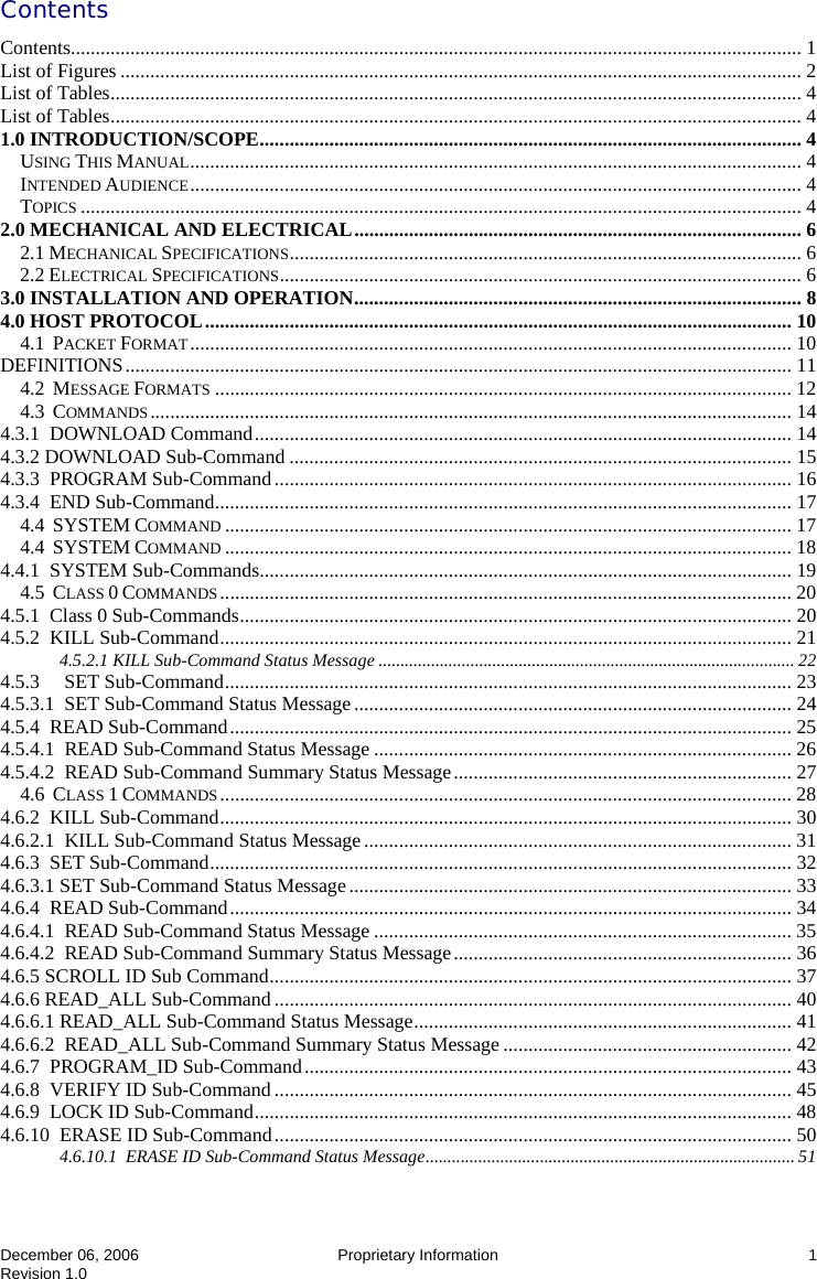
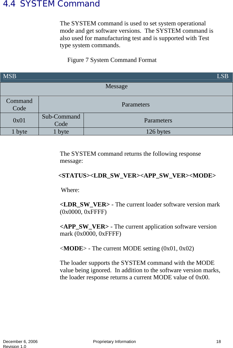
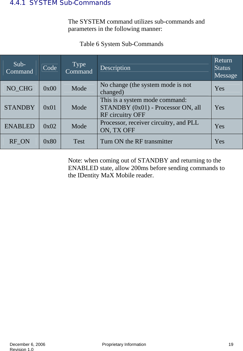
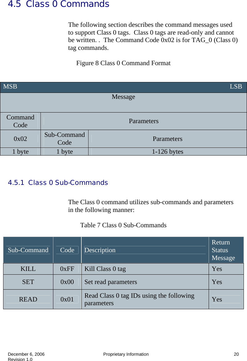
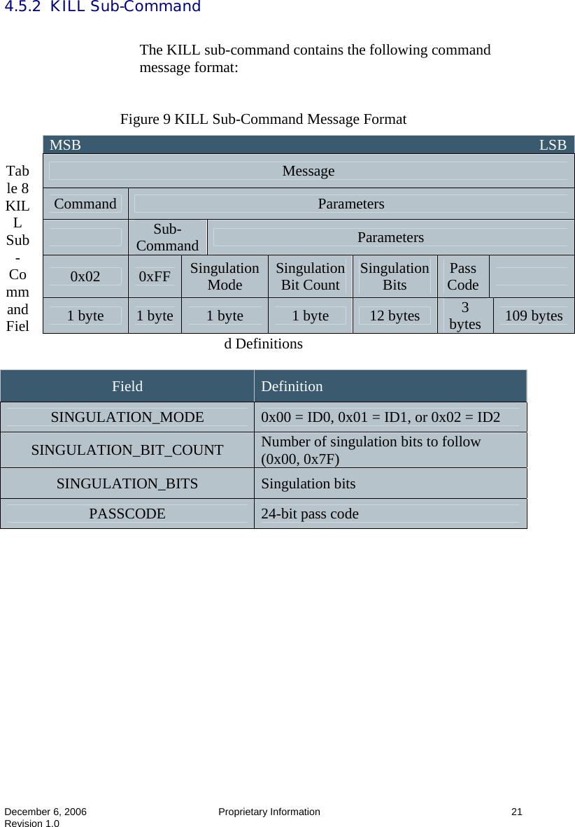
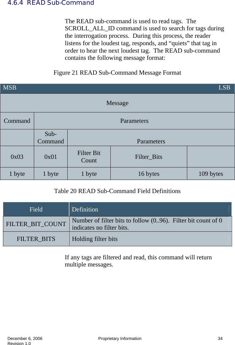
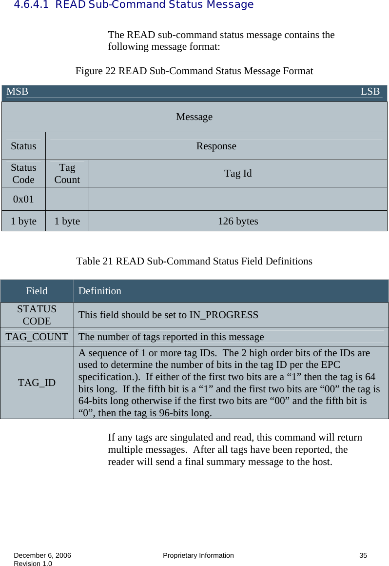
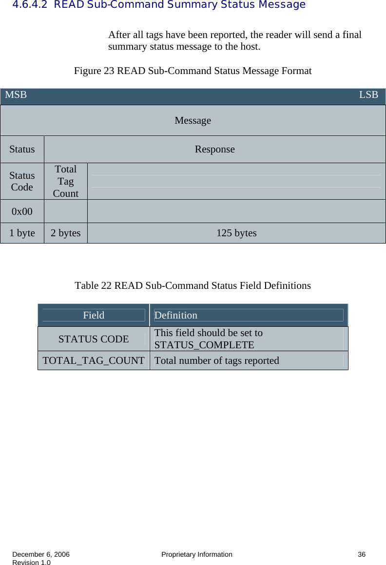
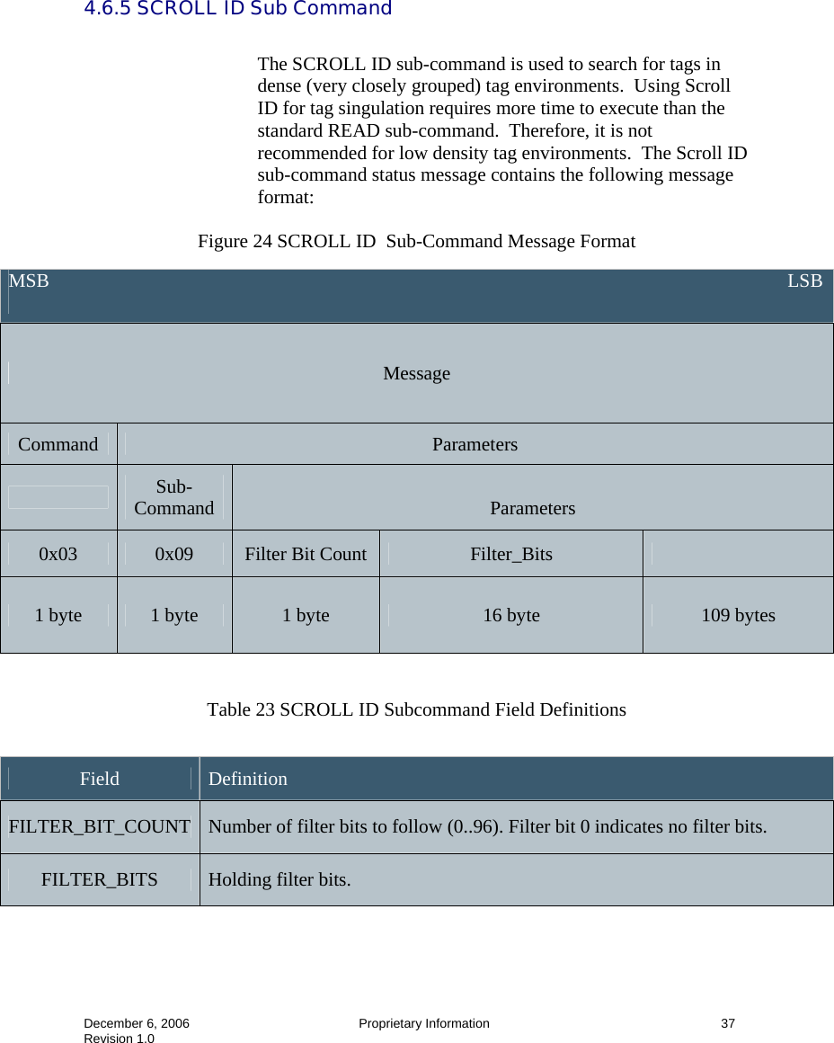
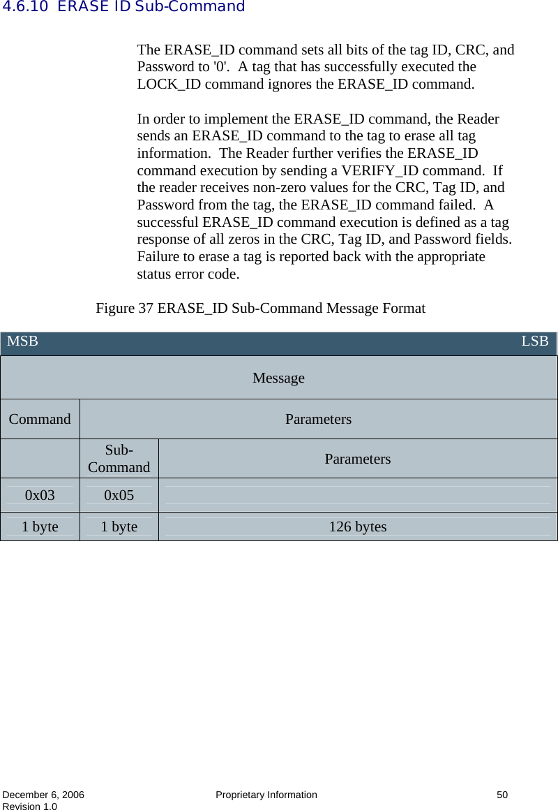
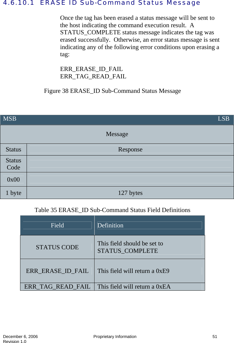
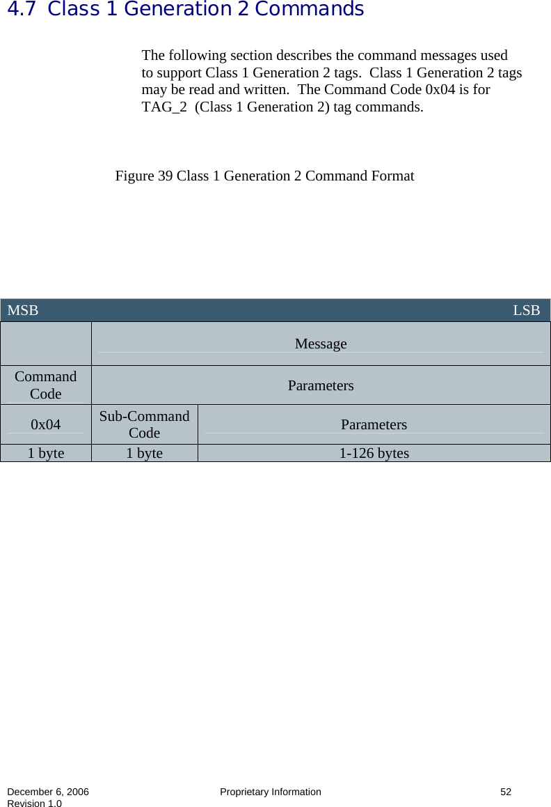
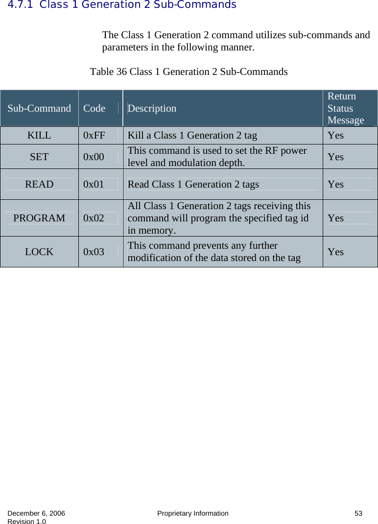
![December 06, 2006 Proprietary Information 4 Revision 1.0 1.0 Introduction/Scope Using This Manual This User’s Guide provides instructions for installing the IDentity MaX Mobile RFID reader and for integrating the host protocol onto a PC based application. Intended Audience This manual is intended for use by technical personnel responsible for installing the IDentity MaX Mobile reader and writing PC applications to communicate with it: • Electrical Engineers • Mechanical Engineers • Software Engineers • Manufacturing Engineers Topics 1 Introduction/Scope Explains the scope of this manual and intended audience 2 Reader Mechanical and Electrical Information Describes the physical and electrical characteristics of the reader 3 Installation and Operation Describes the proper procedures to install and operate the reader 4 Host Protocol Specifies the protocol used to communicate with the reader 5 Troubleshooting Lists possible causes and remedies for operating abnormalities Appendix A CRC Calculation Example CRC-16 calculation and sample “C” code Comment [h1]:](https://usermanual.wiki/3M-Traffic-Safety-Systems/IDMAX015/User-Guide-744863-Page-8.png)
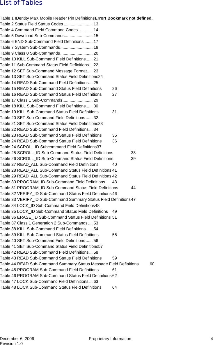
![December 6, 2006 Proprietary Information 68 Revision 1.0 Appendix A CRC Calculation This section shows how to calculate the CCITT CRC-16 over the entire body of the message. The CCITT CRC-16 is calculated starting with the LENGTH byte and continuing through the length -2. The final two CRC bytes are not included in the calculation but should be checked against the CCITT CRC-16 for a match. A typical command string, the Notify Command, with this CRC Calculated follows: 01 05 00 00 27 6C Where the 01 is the SOF byte, the 05 is the length and 00 00 is the command for the Notify Command with the 276C as the correctly calculated CRC. Here is a “C” language listing that shows the CCITT CRC-16 calculation. // *************************************************************************************************** // // CRC_Calc // Calculates CCITT-CRC for IDentity MaX Mobile RFID reader // // Version 1.0 // // This routine calculates the two byte CCITT-CRC for command and data messages for the IDentity MaX Mobile reader UHF RFID // Reader. // // Inputs: Place the entire message to be transmitted including SOH and two empty bytes for CRC into an array. // In this demo case CommandArray and the total length of the command in the length variable, CommandLength // are passed. These are passed into "bytearray[]" and "arraylength" variables of the routine. // // Outputs: This routine will return the value of the two-byte CRC which is calculated in the variable "crc". // // The routine begins with array index [1], and goes to array length -2. You will have to move the two bytes returned // into the last two bytes of the array before transmitting the command. You can also use it to verify received // commands by checking the entire length, i.e. set your length to two more than the actual length of the command. If // the returned, the CRC is "0000" then the command is valid // // **************************************************************************************************** #include <stdio.h> #include <stdlib.h> unsigned short CRC_Calc(char bytearray[256],int arraylength) { unsigned short crc = 0xFFFF; // Preload to FFFF unsigned short tempresults; // Just a temporary results holder unsigned short bitindex; // 0 - 7 unsigned short byteindex; // The byte pointer into the byte // array that holds](https://usermanual.wiki/3M-Traffic-Safety-Systems/IDMAX015/User-Guide-744863-Page-72.png)
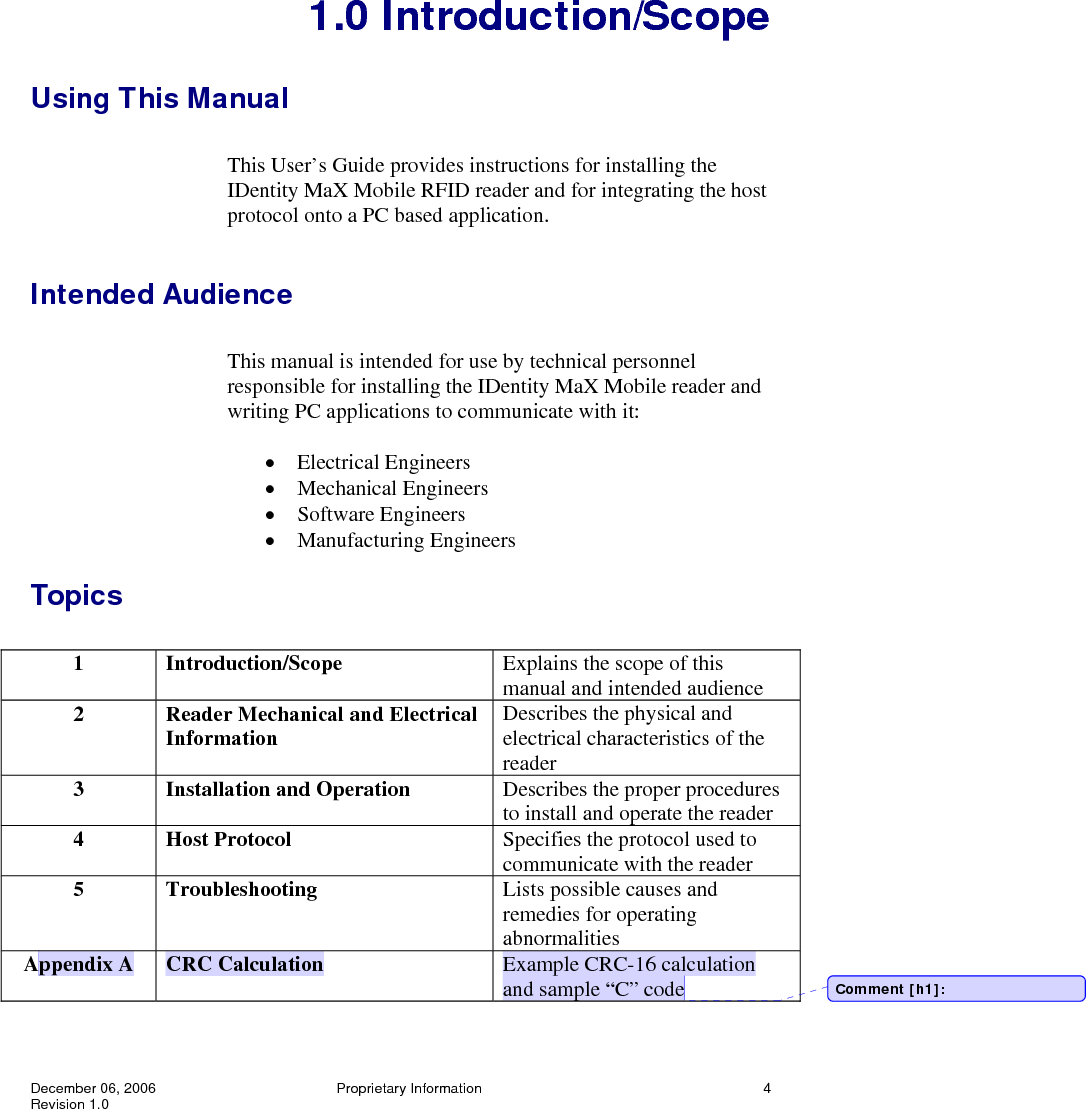
![December 6, 2006 Proprietary Information 69 Revision 1.0 // the command to be checked. unsigned char placeholder; // A place to put the byte while we // work on it. for (byteindex = 1; byteindex <= (arraylength - 3); byteindex++) // begin checking after SOH and // before CRC bytes { placeholder = bytearray[byteindex]; for(bitindex = 0; bitindex <= 7; bitindex++) { tempresults = (crc >> 15) ^ (placeholder >> 7); // Shift CRC right 15 bits then do a // bitwise XOR crc <<= 1; // Shift CRC left one bit and store it // in CRC if(tempresults) { crc ^= 0x1021; // Standard CCITT Polynomial // X16+X12+X5+1 } placeholder <<= 1; } } return crc; // Returns the CRC calculated in // the variable crc }](https://usermanual.wiki/3M-Traffic-Safety-Systems/IDMAX015/User-Guide-744863-Page-73.png)