3M Traffic Safety Systems IDMAX016 RFID Reader User Manual
3M Traffic Safety Systems RFID Reader
User manual
December 06, 2006 Proprietary Information 2
Revision 1.0
December 6, 2006 Proprietary Information 3
Revision 1.0
This equipment complies with FCC Part 15.247 and Industry Canada RSS-210 rules. Any changes or modifications
not expressly approved by SIRIT could void the user’s authority to operate the equipment. To maintain compliance,
the IDentity MaX Desktop reader must be used with the power supply that was supplied with the reader.
RF Exposure Warning
To comply with the FCC radiofrequency (RF) Exposure requirements, the antenna(s) used with this device must be
installed to provide a minimum separation distance of 20 cm from all persons
Part Number: IDentity MaX Desktop User’s Guide
Release Date: Dec 6, 2006
IDentity MaX Desktop Users Guide_1.0.doc
December 06, 2006 Proprietary Information 1
Revision 1.0
Contents
Contents................................................................................................................................................... 1
List of Figures ......................................................................................................................................... 2
List of Tables........................................................................................................................................... 4
List of Tables........................................................................................................................................... 4
1.0 INTRODUCTION/SCOPE............................................................................................................. 4
USING THIS MANUAL........................................................................................................................... 4
INTENDED AUDIENCE........................................................................................................................... 4
TOPICS ................................................................................................................................................. 4
2.0 MECHANICAL AND ELECTRICAL.......................................................................................... 6
2.1 MECHANICAL SPECIFICATIONS....................................................................................................... 6
2.2 ELECTRICAL SPECIFICATIONS......................................................................................................... 6
3.0 INSTALLATION AND OPERATION.......................................................................................... 8
4.0 HOST PROTOCOL...................................................................................................................... 10
4.1 PACKET FORMAT......................................................................................................................... 10
DEFINITIONS...................................................................................................................................... 11
4.2 MESSAGE FORMATS .................................................................................................................... 12
4.3 COMMANDS................................................................................................................................. 14
4.3.1 DOWNLOAD Command............................................................................................................ 14
4.3.2 DOWNLOAD Sub-Command ..................................................................................................... 15
4.3.3 PROGRAM Sub-Command........................................................................................................ 16
4.3.4 END Sub-Command.................................................................................................................... 17
4.4 SYSTEM COMMAND .................................................................................................................. 17
4.4 SYSTEM COMMAND .................................................................................................................. 18
4.4.1 SYSTEM Sub-Commands........................................................................................................... 19
4.5 CLASS 0 COMMANDS................................................................................................................... 20
4.5.1 Class 0 Sub-Commands............................................................................................................... 20
4.5.2 KILL Sub-Command................................................................................................................... 21
4.5.2.1 KILL Sub-Command Status Message............................................................................................. 22
4.5.3 SET Sub-Command.................................................................................................................. 23
4.5.3.1 SET Sub-Command Status Message........................................................................................ 24
4.5.4 READ Sub-Command................................................................................................................. 25
4.5.4.1 READ Sub-Command Status Message .................................................................................... 26
4.5.4.2 READ Sub-Command Summary Status Message.................................................................... 27
4.6 CLASS 1 COMMANDS................................................................................................................... 28
4.6.2 KILL Sub-Command................................................................................................................... 30
4.6.2.1 KILL Sub-Command Status Message...................................................................................... 31
4.6.3 SET Sub-Command..................................................................................................................... 32
4.6.3.1 SET Sub-Command Status Message......................................................................................... 33
4.6.4 READ Sub-Command................................................................................................................. 34
4.6.4.1 READ Sub-Command Status Message .................................................................................... 35
4.6.4.2 READ Sub-Command Summary Status Message.................................................................... 36
4.6.5 SCROLL ID Sub Command......................................................................................................... 37
4.6.6 READ_ALL Sub-Command........................................................................................................ 40
4.6.6.1 READ_ALL Sub-Command Status Message............................................................................ 41
4.6.6.2 READ_ALL Sub-Command Summary Status Message .......................................................... 42
4.6.7 PROGRAM_ID Sub-Command.................................................................................................. 43
4.6.8 VERIFY ID Sub-Command ........................................................................................................ 45
4.6.9 LOCK ID Sub-Command............................................................................................................ 48
4.6.10 ERASE ID Sub-Command........................................................................................................ 50
4.6.10.1 ERASE ID Sub-Command Status Message.................................................................................. 51
December 6, 2006 Proprietary Information 2
Revision 1.0
4.7 CLASS 1 GENERATION 2 COMMANDS .......................................................................................... 52
4.7.1 Class 1 Generation 2 Sub-Commands......................................................................................... 53
4.7.2 KILL Sub-Command................................................................................................................... 54
4.7.2.1 KILL Sub-Command Status Message...................................................................................... 55
4.7.3 SET Sub-Command..................................................................................................................... 56
4.7.3.1 SET Sub-Command Status Message......................................................................................... 57
4.7.4 READ Sub-Command................................................................................................................. 58
4.7.4.1 READ Sub-Command Status Message .................................................................................... 59
4.7.4.2 READ Sub-Command Summary Status Message.................................................................... 60
4.7.5 PROGRAM Sub-Command........................................................................................................ 61
4.7.5.1 PROGRAM Sub-Command Status Message............................................................................ 62
4.7.6 LOCK Sub-Command................................................................................................................. 63
4.7.6.1 C1G2 LOCK Sub-Command Status Message.......................................................................... 64
5.0 TROUBLESHOOTING............................................................................................................... 65
Chapter 6
No Response from Reader..................................................................................................................... 65
Tags Will Not Read............................................................................................................................... 66
Poor Read Range/Intermittent Tag Reads ............................................................................................. 67
APPENDIX A CRC CALCULATION............................................................................................. 68
List of Figures
Figure 1 Packet Format .......................................... 10
Figure 2 Command Message Field Format ............ 12
Figure 3 Response Message Field Format............. 12
Figure 4 Download Command Format.................... 14
Figure 5 PROGRAM Sub-Command Message Format 16
Figure 6 END Sub-Command Message Format..... 17
Figure 7 System Command Format........................ 18
Figure 9 Class 0 Command Format........................ 20
Figure 10 KILL Sub-Command Message Format... 21
Figure 11 KILL Sub-Command Status Message Format 22
Figure 12 SET Sub-Command Message Format ... 23
Figure 13 SET Sub-Command Status Message Format 24
Figure 14 READ Sub-Command Message Format 25
Figure 15 READ Sub-Command Status Message Format 26
Figure 16 READ Sub-Command Status Message Format 27
Figure 17 Class 1 Command Format...................... 28
Figure 18 KILL Sub-Command Message Format... 30
Figure 19 KILL Sub-Command Status Message Format 31
Figure 20 SET Sub-Command Message Format ... 32
Figure 21 SET Sub-Command Status Message Format 33
Figure 22 READ Sub-Command Message Format 34
Figure 23 READ Sub-Command Status Message Format 35
Figure 24 READ Sub-Command Status Message Format 36
Figure 25 SCROLL ID Sub-Command Message Format 37
Figure 26 SCROLL_ID Sub-Command Status Message Format 38
Figure 27 SCROLL_ID Sub-Command Status Message Format 39
Figure 28 READ_ALL Sub-Command Message Format 40
Figure 29 READ_ALL Sub-Command Status Message Format 41
Figure 30 READ_ALL Sub-Command Status Message Format 42
Figure 31 PROGRAM_ID Sub-Command Message Format 43
Figure 32 PROGRAM_ID Sub-Command Status Message Format 44
Figure 33 VERIFY_ID Sub-Command Message Format 45
December 6, 2006 Proprietary Information 3
Revision 1.0
Figure 34 VERIFY_ID Sub-Command Status Message Format 46
Figure 35 VERIFY_ID Sub-Command Summary Status Message Format 47
Figure 36 LOCK_ID Sub-Command Message Format48
Figure 37 LOCK_ID Sub-Command Status Message Format 49
Figure 38 ERASE_ID Sub-Command Message Format 50
Figure 39 ERASE_ID Sub-Command Status Message 51
Figure 40 Class 1 Generation 2 Command Format 52
Figure 41 KILL Sub-Command Message Format... 54
Figure 42 KILL Sub-Command Status Message Format 55
Figure 43 SET Sub-Command Message Format ... 56
Figure 44 SET Sub-Command Status Message Format 57
Figure 45 READ Sub-Command Message Format 58
Figure 46 READ Sub-Command Status Message Format 59
Figure 47 READ Sub-Command Summary Status Message Format 60
Figure 48 PROGRAM Sub-Command Message Format 61
Figure 49 PROGRAM Sub-Command Status Message Format 62
Figure 50 LOCK Sub-Command Message Format. 63
Figure 51 LOCK Sub-Command Status Message Format 64

December 6, 2006 Proprietary Information 4
Revision 1.0
List of Tables
Table 1 IDentity MaX Desktop Reader Pin Definitions7
Table 2 Status Field Status Codes ......................... 13
Table 4 Command Field Command Codes ............ 14
Table 5 Download Sub-Commands........................ 15
Table 6 END Sub-Command Field Definitions ....... 17
Table 7 System Sub-Commands............................ 19
Table 9 Class 0 Sub-Commands............................ 20
Table 10 KILL Sub-Command Field Definitions...... 21
Table 11 Sub-Command Status Field Definitions... 22
Table 12 SET Sub-Command Message Format..... 23
Table 13 SET Sub-Command Status Field Definitions24
Table 14 READ Sub-Command Field Definitions... 25
Table 15 READ Sub-Command Status Field Definitions 26
Table 16 READ Sub-Command Status Field Definitions 27
Table 17 Class 1 Sub-Commands.......................... 29
Table 18 KILL Sub-Command Field Definitions...... 30
Table 19 KILL Sub-Command Status Field Definitions 31
Table 20 SET Sub-Command Field Definitions...... 32
Table 21 SET Sub-Command Status Field Definitions33
Table 22 READ Sub-Command Field Definitions... 34
Table 23 READ Sub-Command Status Field Definitions 35
Table 24 READ Sub-Command Status Field Definitions 36
Table 24 SCROLL ID Subcommand Field Definitions37
Table 25 SCROLL_ID Sub-Command Status Field Definitions 38
Table 26 SCROLL_ID Sub-Command Status Field Definitions 39
Table 27 READ_ALL Sub-Command Field Definitions 40
Table 28 READ_ALL Sub-Command Status Field Definitions 41
Table 29 READ_ALL Sub-Command Status Field Definitions 42
Table 30 PROGRAM_ID Sub-Command Field Definitions 43
Table 31 PROGRAM_ID Sub-Command Status Field Definitions 44
Table 32 VERIFY_ID Sub-Command Status Field Definitions 46
Table 33 VERIFY_ID Sub-Command Summary Status Field Definitions 47
Table 34 LOCK_ID Sub-Command Field Definitions48
Table 35 LOCK_ID Sub-Command Status Field Definitions 49
Table 36 ERASE_ID Sub-Command Status Field Definitions 51
Table 37 Class 1 Generation 2 Sub-Commands .... 53
Table 38 KILL Sub-Command Field Definitions...... 54
Table 39 KILL Sub-Command Status Field Definitions 55
Table 40 SET Sub-Command Field Definitions...... 56
Table 41 SET Sub-Command Status Field Definitions57
Table 42 READ Sub-Command Field Definitions... 58
Table 43 READ Sub-Command Status Field Definitions 59
Table 44 READ Sub-Command Summary Status Message Field Definitions 60
Table 45 PROGRAM Sub-Command Field Definitions 61
Table 46 PROGRAM Sub-Command Status Field Definitions 62
Table 47 LOCK Sub-Command Field Definitions ... 63
Table 48 LOCK Sub-Command Status Field Definitions 64

December 06, 2006 Proprietary Information 4
Revision 1.0
1.0 Introduction/Scope
Using This Manual
This User’s Guide provides instructions for installing the
IDentity MaX Desktop RFID reader and for integrating the
host protocol onto a PC based application.
Intended Audience
This manual is intended for use by technical personnel
responsible for installing IDentity MaX Desktop reader and
writing PC applications to communicate with it:
• Electrical Engineers
• Mechanical Engineers
• Software Engineers
• Manufacturing Engineers
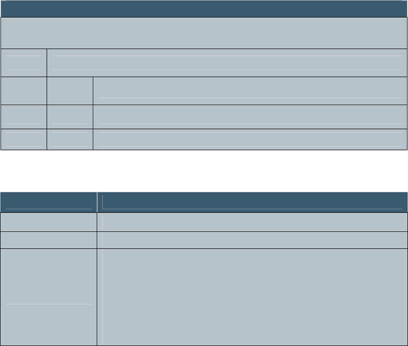
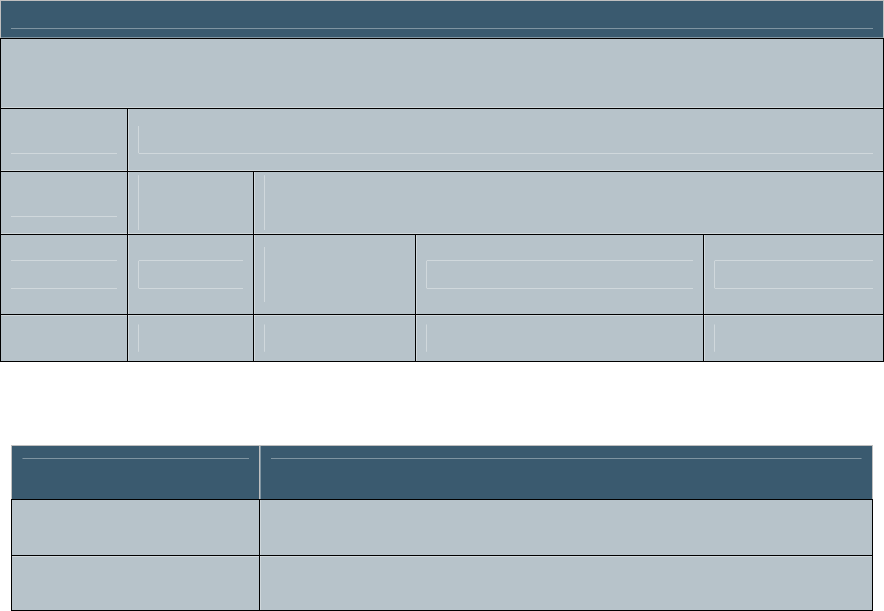
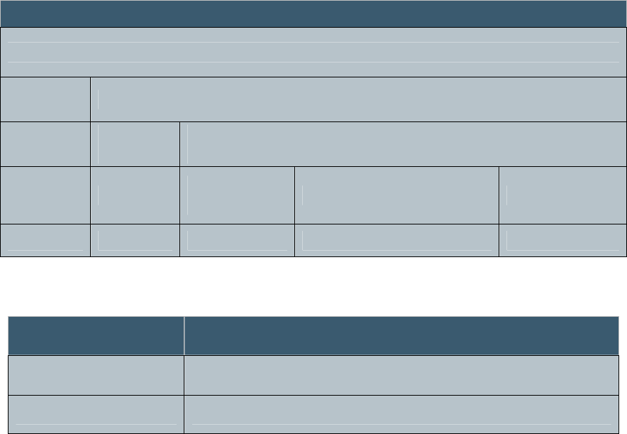
Topics
1
Introduction/Scope Explains the scope of this
manual and intended audience
2 Reader Mechanical and Electrical
Information Describes the physical and
electrical characteristics of the
reader
3 Installation and Operation Describes the proper procedures
to install and operate the reader
4 Host Protocol Specifies the protocol used to
communicate with the reader
5 Troubleshooting Lists possible causes and
remedies for operating
abnormalities
Appendix A CRC Calculation Example CRC-16 calculation
and sample “C” code
December 6, 2006 Proprietary Information 5
Revision 1.0
December 6, 2006 Proprietary Information 6
Revision 1.0
2.0 Mechanical and Electrical
2.1 Mechanical Specifications
Dimensions (LxWxD)
5.75” x 3.25” x 2.25” (not including cables)
Weight
1 lb, 7 oz.
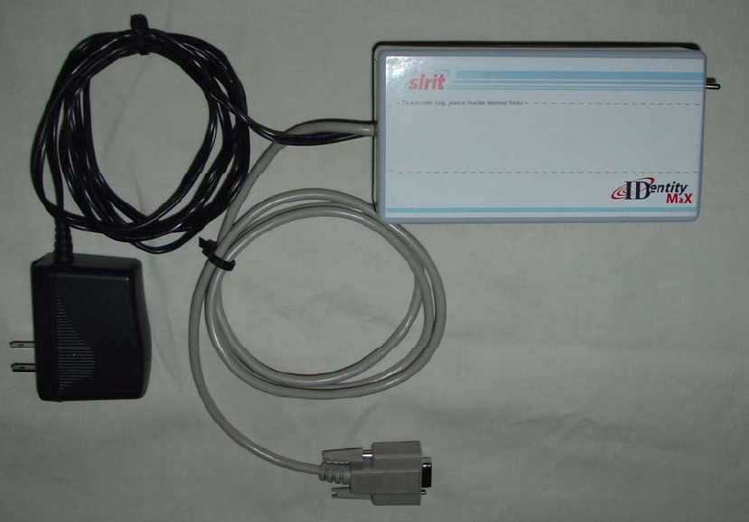
Cables and Connectors
Data: 6 ft. Serial Cable with DB-9S (Female) connector
Power: 6 ft. cable with attached power supply using a two
prong, non-polarized, North American power connector

December 6, 2006 Proprietary Information 7
Revision 1.0
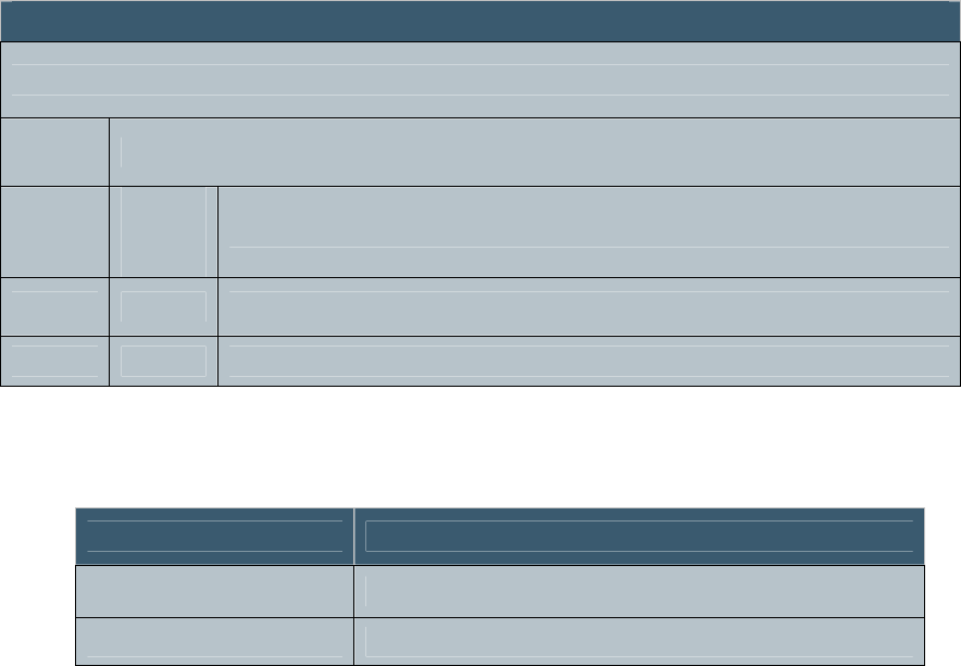
2.2 Electrical Specifications
Table 1 IDentity MaX Desktop reader UHF RFID Reader Pin Definitions
Pin Number Pin Description
1 No Connection
2 RXD – Receive Serial Data
3 TXD – Transmit Serial Data
4 No Connection
5 Ground
6 No Connection
7 DTR – Data Terminal Ready
8 No Connection
9 No Connection
Input voltage 120 VAC 60 Hz / 5VDC, 2A max
RF output power 5dBm
Frequency UHF band, 902 - 928 MHz
Communications Protocol Serial with CCITT CRC-16 error detection
Communications Parameters 115200 bps, 8 data bits, no parity, 1 stop bit
Communications Signal Level Serial data at RS-232 logic levels
Regulatory FCC Part 15
December 6, 2006 Proprietary Information 8
Revision 1.0
3.0 Installation and Operation
3.1 Installation
The following steps are recommended to properly install the
IDentity MaX Desktop reader.
1. Unpack the contents of the shipping container.
2. Inspect the shipping container and contents for damage. If
damaged, notify the carrier and Sirit. Keep all shipping
materials for inspection by the carrier.
3. Determine the location of the reader. It will need to be
within 6 feet of the PC that will be hosting the user
application and within 6 feet of an AC power outlet.
4. Plug the AC power supply of the Desktop reader into the
AC power outlet.
5. Align the DB 9 connector with the serial port connector on
the host PC. Insert firmly. Screw down the thumbscrews
to ensure retention in the connector.
6. Rotate the unit so that the toggle switch and LED face the
operator.
3.2 Operation
The following steps are required to ensure proper operation of
the IDentity MaX Desktop reader:
1. Verify that all power and host PC connections are made.
2. Move the toggle switch on the front of the unit to the ON
(up) position.
3. Verify that the “Power On” LED illuminates.
4. Start the user application on the Host PC.
5. Place the RFID tag being read on the Desktop reader within
the dotted lines shown on the top of the reader. Contact
with the top of the reader must be maintained in order to
obtain a proper tag read transaction.
December 6, 2006 Proprietary Information 9
Revision 1.0
NOTE: To avoid erroneous tag reads, keep all RFID tags
other than the one being processed at least 1ft. away from
the IDentity MaX Desktop reader.
6. Perform the required operations as specified by the user
application and procedures.
7. After all tag transactions have been processed, flip the
toggle switch on the front of the reader to the OFF (down)
position.

December 6, 2006 Proprietary Information 10
Revision 1.0
4.0 Host Protocol
The Host Protocol supports communications between the
IDentity MaX Desktop reader and a Host. The following
sections define this protocol by breaking down the different
fields and layers of the packet protocol.
This interface uses the serial port on the IDentity MaX Desktop
reader. The serial port interface will be configured to transfer
data at 115,200 bps, 8 data bits, no parity, and 1 stop bit.
4.1 Packet Format
The protocol is Byte Oriented (packets and messages are a
sequence of bytes). All multi-byte commands, parameters and
responses are encoded MSB first. All bit field parameters or
responses are encoded left justified (MSBit in high order bit of
MSByte).
Figure 1 Packet Format
MSB LSB
SOF (0x01) Length Message CRC
1 byte 1 byte 1-128 bytes 2 bytes
December 6, 2006 Proprietary Information 11
Revision 1.0
DEFINITIONS
CRC: Two bytes, CCITT CRC-16 calculated over the
LENGTH field through the end of MESSAGE field in the
FORWARD direction with a PRELOAD of 0xFFFF. If the
CRC is calculated incorrectly, the reader will not respond. See
Appendix A.
LENGTH: Number of bytes in the packet from the LENGTH
byte through the end of the CRC, excluding the SOF
MESSAGE: Commands or responses
SOF: 0x01 Start-Of-Frame, byte field used to indicate the start
of a packet boundary
December 6, 2006 Proprietary Information 12
Revision 1.0
4.2 Message Formats
The MESSAGE portion of a packet is used to transport both
commands from the host to the reader and responses from the
reader to the host. The reader will not send autonomous
(unsolicited) responses.
Command messages contain a one byte “Command” field.
Following the command byte field is the “Parameter” field that
could contain zero to many parameters associated with the
command field.
Figure 2 Command Message Field Format
Response messages contain a one byte “Status” field that is
common to all reader responses. The “Status” field contains an
indication of the reader status. Following the status byte is the
“Response” field that could contain zero to many responses
associated with the “Status” field.
Figure 3 Response Message Field Format
MSB LSB
Message
Command Parameters
1 byte 127 bytes
MSB LSB
Message
Status Response
1 byte 127 bytes

December 6, 2006 Proprietary Information 13
Revision 1.0
The “Status” field contains the following status codes:
Table 2 Status Field Status Codes
Status Status
Code Description
STATUS_ERROR 0xFF The command processing is complete with
errors or faults detected.
STATUS_COMPLETE 0x00 The command has completed with no errors
or faults encountered.
STATUS_IN_PROGRESS 0x01 The reader is still processing the command.
More response data is to be expected.

December 6, 2006 Proprietary Information 14
Revision 1.0
4.3 Commands
The following table shows all the commands that are supported
for command processing on the reader:
Table 3 Command Field Command Codes
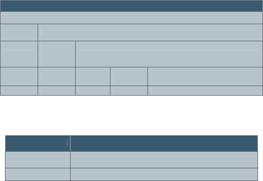
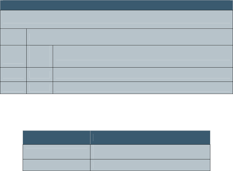
4.3.1 DOWNLOAD Command
The DOWNLOAD command is used to download new
application software to the reader.
Figure 4 Download Command Format
Command Code Description
DOWNLOAD 0x00 Download new application software to the reader
SYSTEM 0x01 Set system operational mode and get software
versions
TAG_0 0x02 Class 0 tag commands
TAG_1 0x03 Class 1 tag commands
TAG_G2 0x04 Class 1 Generation 2 commands
MSB LSB
Message
Command
Code Parameters
0x00 Sub-
Command
Code Parameters
1 byte 1 byte 126 bytes

December 6, 2006 Proprietary Information 15
Revision 1.0
4.3.2 DOWNLOAD Sub-Command
The DOWNLOAD command further utilizes sub-commands
and parameters to support the download process in the reader.
Table 4 Download Sub-Commands
Sub-Command Code Description Return
Status
Message
NOTIFY 0x00
Both the reader and the application accept this
command. If the application receives this
command it will respond and reboot into the
application into the reader. If the reader receives
this command it will reboot the reader and then
respond
Yes
START 0x01
Only the reader accepts this sub-command.
Notifies the reader to erase the application area of
flash memory. During the flash erase process, the
reader may return several status messages of
IN_PROGRESS before returning a completion
status.
Yes
PROGRAM 0x02
Only the reader accepts this sub-command. A
variable length message containing data to
beprogrammed into flash. The reader will
calculate a cumulative CRC of the data as it is
being downloaded During the flash programming
process, the reader may return several status
messages of IN_PROGRESS before returning a
completion status.
Yes
END 0x03
Only the reader accepts this sub-command.
Notifies the reader that there are no more
PROGRAM messages. Upon receipt, the reader
will compare CRC values then program the
application header into flash. During the flash
programming process, the reader may return
several status IN_PROGRESS messages before
returning a completion status.
Yes
REBOOT 0x04 Both the reader and the application accept this
sub-command. After responding to this command
the system will reboot. Yes

December 6, 2006 Proprietary Information 16
Revision 1.0
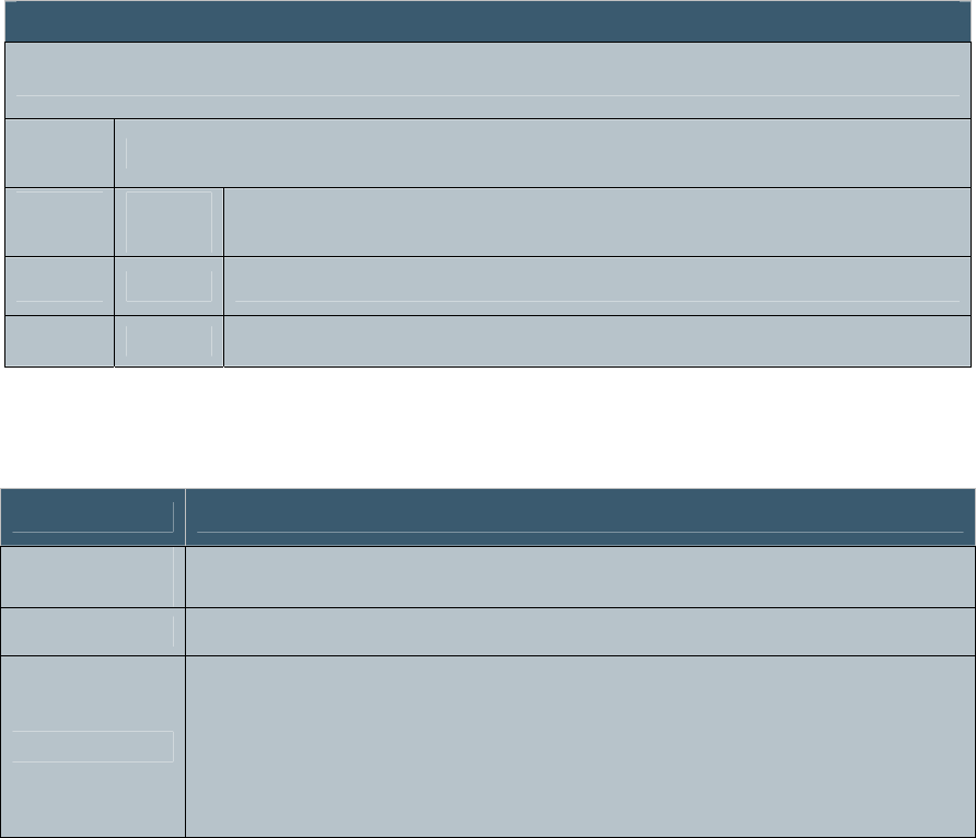
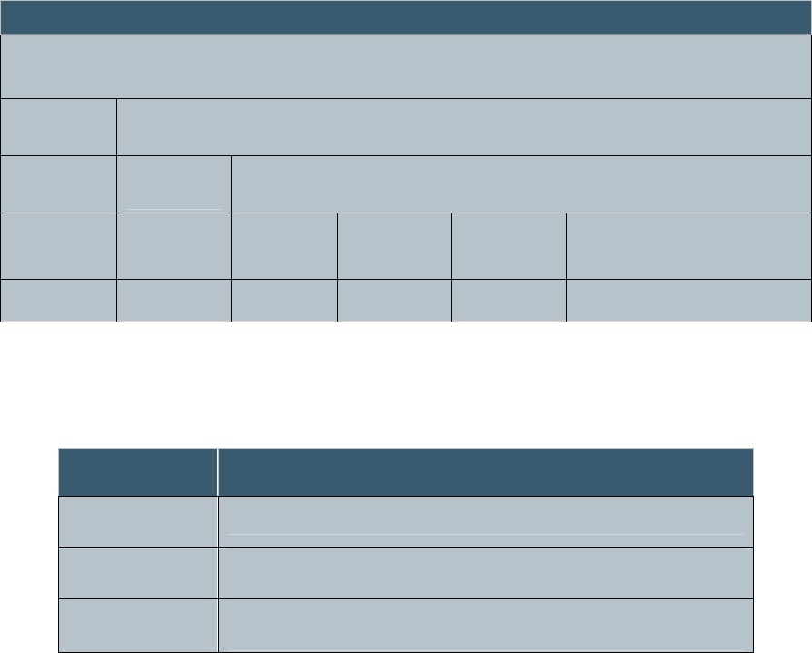
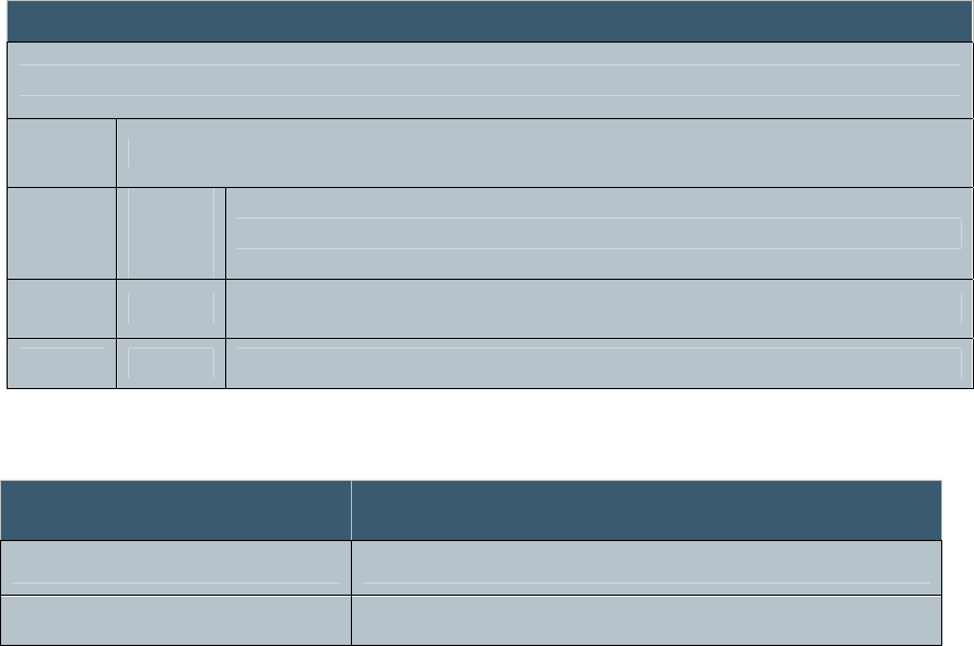
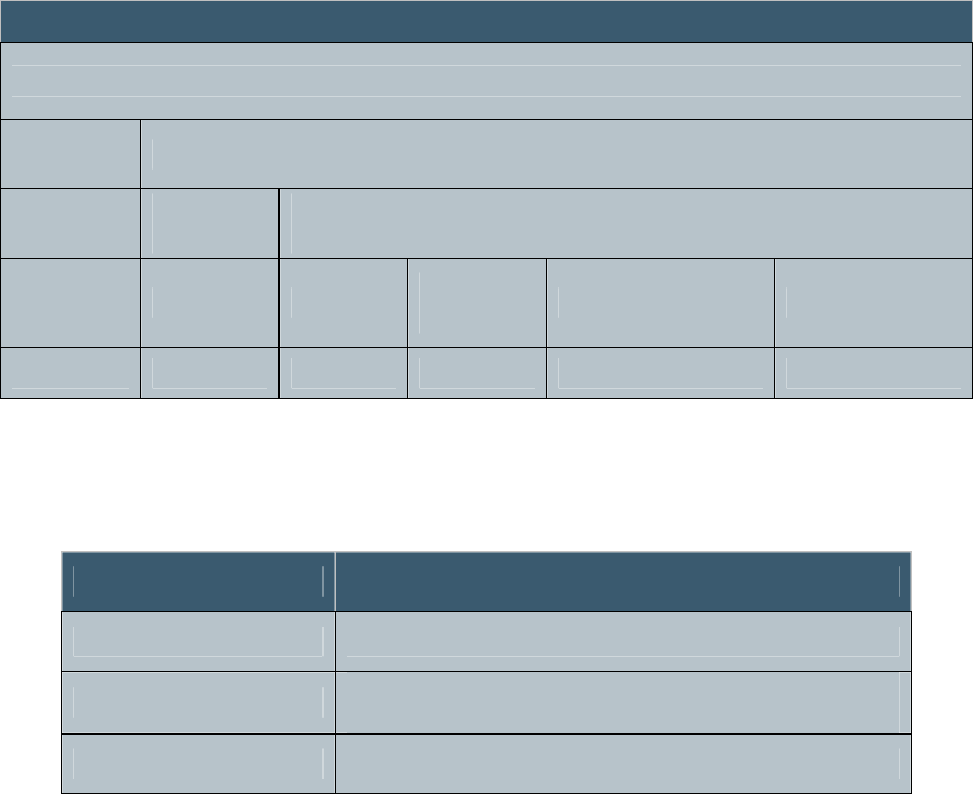
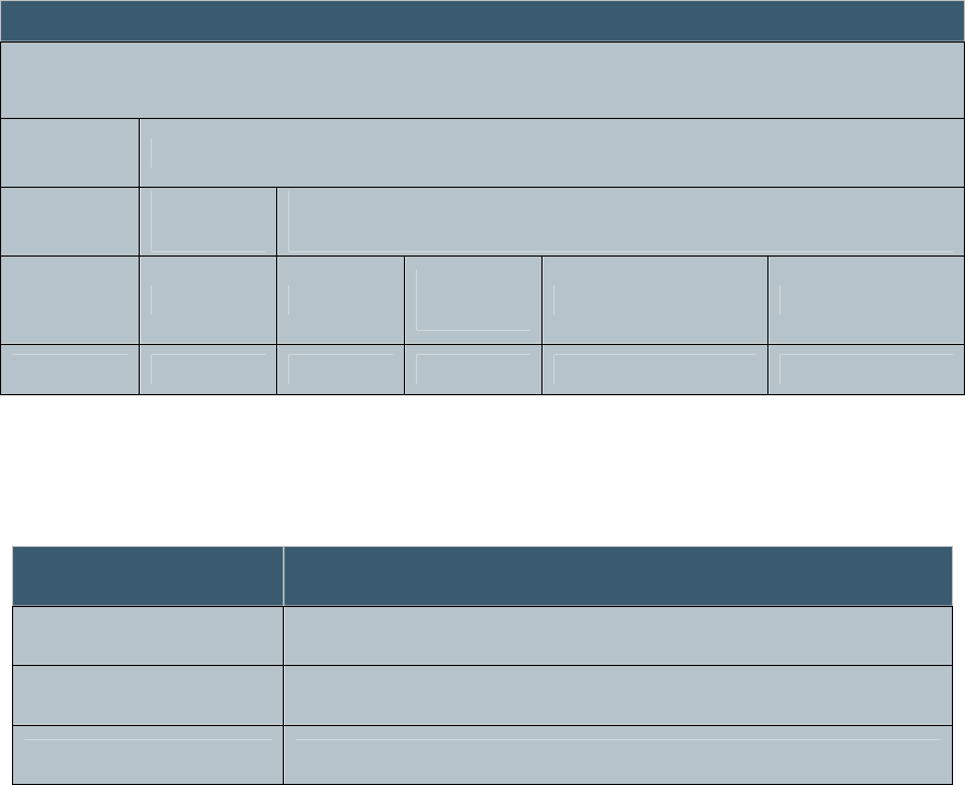
4.3.3 PROGRAM Sub-Command
The PROGRAM sub-command contains the following message
format for programming the flash. The DATA field will
contain one or more bytes of data that needs to be programmed.
Figure 5 PROGRAM Sub-Command Message Format
MSB LSB
Message
Command
Code
Parameters
Sub-
Command
Code
Parameters
0x00 0x02 Address Data
1 byte 1 byte 4 bytes 122 bytes
December 6, 2006 Proprietary Information 17
Revision 1.0
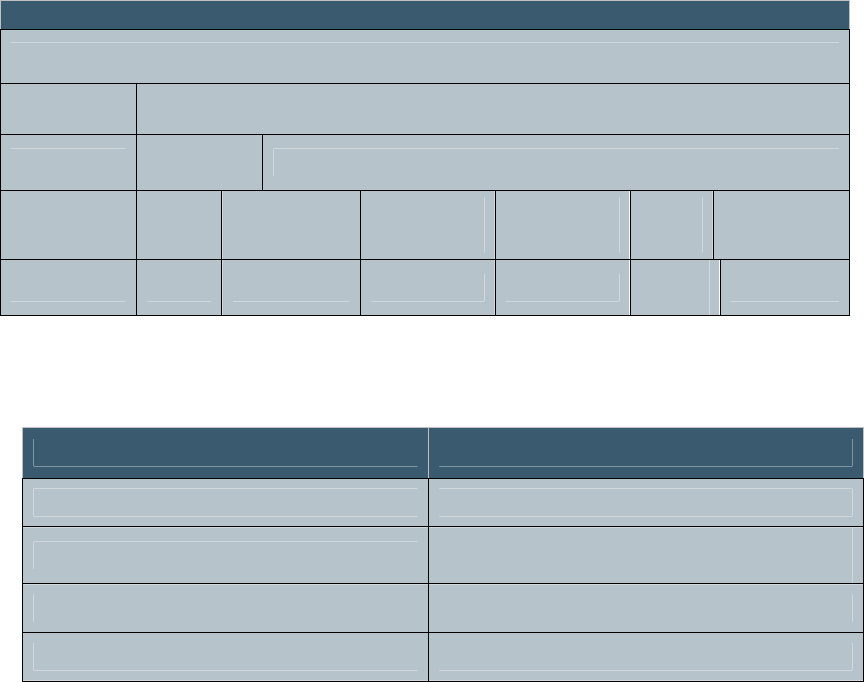
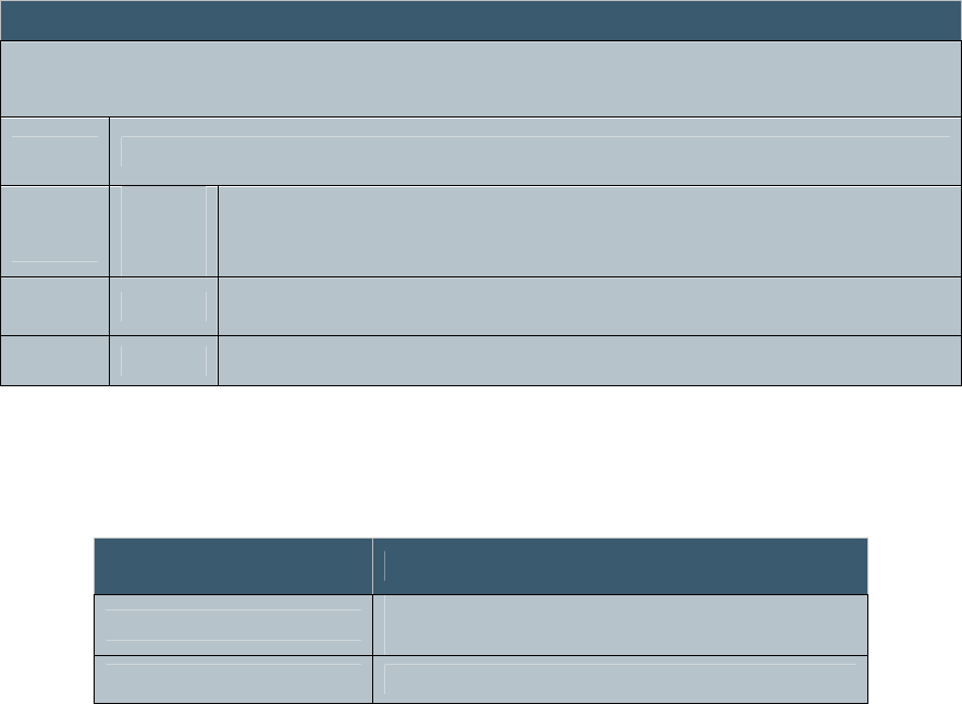
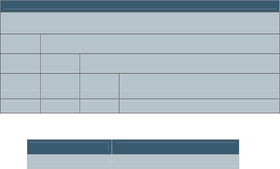
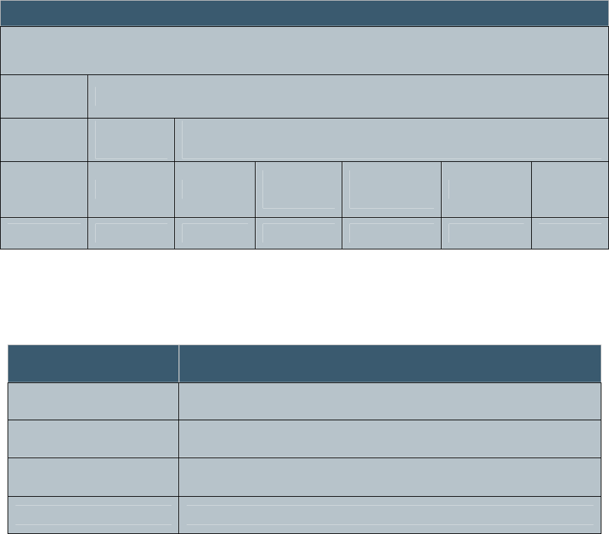
4.3.4 END Sub-Command
The END sub-command notifies the reader that there are no
more PROGRAM messages, compares the CRC values, and
programs the application header into flash. The END sub-
command contains the following message format:
Figure 6 END Sub-Command Message Format
Table 5 END Sub-Command Field Definitions
MSB LSB
Message
Command
Code Parameters
Sub-
Command
Code Parameters
0x00 0x03 CRC Start
Address Parameters
1 byte 1 byte 2 bytes 4 bytes 120 bytes
Field Definition
CRC 2-byte CCITT CRC-16 of all program data (forward with
0xFFFF pre-load)
START_ADDRESS 4-byte address at which to start code execution

December 6, 2006 Proprietary Information 18
Revision 1.0
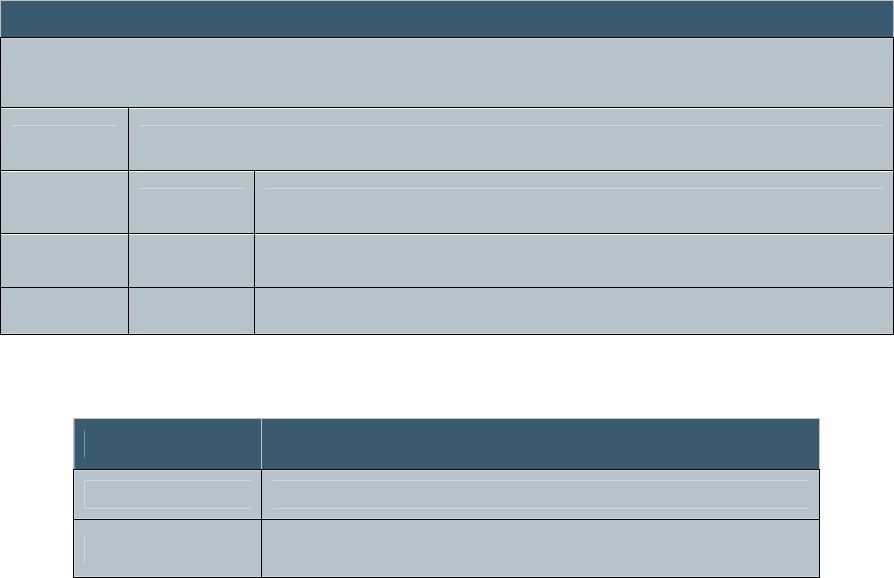
4.4 SYSTEM Command
The SYSTEM command is used to set system operational
mode and get software versions. The SYSTEM command is
also used for manufacturing test and is supported with Test
type system commands.
Figure 7 System Command Format
The SYSTEM command returns the following response
message:
<STATUS><LDR_SW_VER><APP_SW_VER><MODE>
Where:
<LDR_SW_VER> - The current loader software version mark
(0x0000, 0xFFFF)
<APP_SW_VER> - The current application software version
mark (0x0000, 0xFFFF)
<MODE> - The current MODE setting (0x01, 0x02)
The loader supports the SYSTEM command with the MODE
value being ignored. In addition to the software version marks,
the loader response returns a current MODE value of 0x00.
MSB LSB
Message
Command
Code Parameters
0x01 Sub-Command
Code Parameters
1 byte 1 byte 126 bytes

December 6, 2006 Proprietary Information 19
Revision 1.0
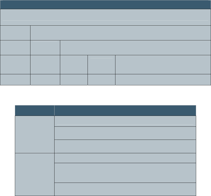
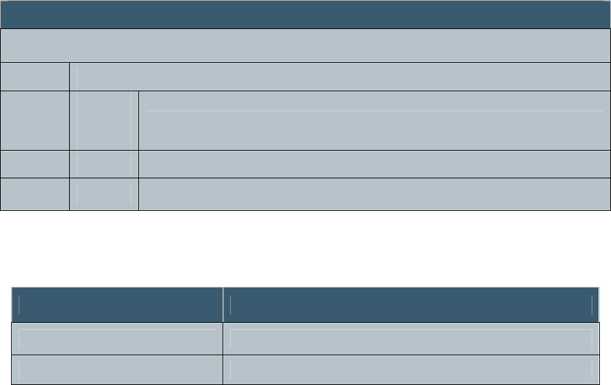
4.4.1 SYSTEM Sub-Commands
The SYSTEM command utilizes sub-commands and
parameters in the following manner:
Table 6 System Sub-Commands
Note: when coming out of STANDBY and returning to the
ENABLED state, allow 200ms before sending commands to
the IDentity MaX Desktop reader.
Sub-
Command Code Type
Command Description Return
Status
Message
NO_CHG 0x00 Mode No change (the system mode is not
changed) Yes
STANDBY 0x01 Mode This is a system mode command:
STANDBY (0x01) - Processor ON, all
RF circuitry OFF Yes
ENABLED 0x02 Mode Processor, receiver circuitry, and PLL
ON, TX OFF Yes
RF_ON 0x80 Test Turn ON the RF transmitter Yes

December 6, 2006 Proprietary Information 20
Revision 1.0
4.5 Class 0 Commands
The following section describes the command messages used
to support Class 0 tags. Class 0 tags are read-only and cannot
be written. . The Command Code 0x02 is for TAG_0 (Class 0)
tag commands.
Figure 8 Class 0 Command Format
4.5.1 Class 0 Sub-Commands
The Class 0 command utilizes sub-commands and parameters
in the following manner:
Table 7 Class 0 Sub-Commands
Sub-Command Code Description Return
Status
Message
KILL 0xFF Kill Class 0 tag Yes
SET 0x00 Set read parameters Yes
READ 0x01 Read Class 0 tag IDs using the following
parameters Yes
MSB LSB
Message
Command
Code Parameters
0x02 Sub-Command
Code Parameters
1 byte 1 byte 1-126 bytes
December 6, 2006 Proprietary Information 21
Revision 1.0
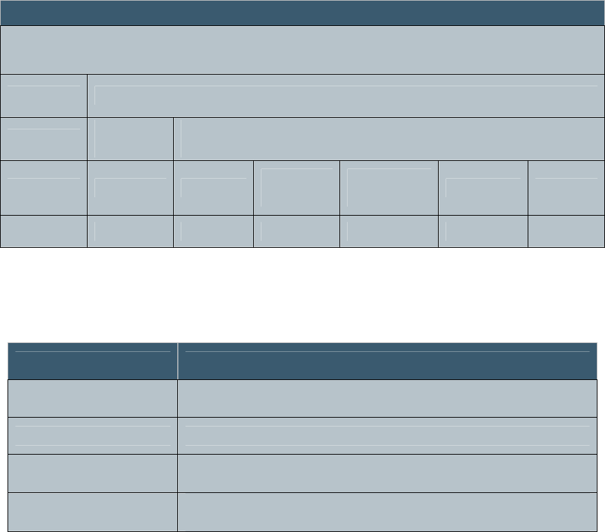
4.5.2 KILL Sub-Command
The KILL sub-command contains the following command
message format:
Figure 9 KILL Sub-Command Message Format
Table 8 KILL Sub-Command Field Definitions
Field Definition
SINGULATION_MODE 0x00 = ID0, 0x01 = ID1, or 0x02 = ID2
SINGULATION_BIT_COUNT Number of singulation bits to follow
(0x00, 0x7F)
SINGULATION_BITS Singulation bits
PASSCODE 24-bit pass code
MSB LSB
Message
Command Parameters
Sub-
Command Parameters
0x02 0xFF Singulation
Mode Singulation
Bit Count Singulation
Bits Pass
Code
1 byte 1 byte 1 byte 1 byte 12 bytes 3
bytes 109 bytes

December 6, 2006 Proprietary Information 22
Revision 1.0
4.5.2.1 KILL Sub-Command Status Message
The KILL sub-command status message contains the following
message format:
Figure 10 KILL Sub-Command Status Message Format
Table 9 Sub-Command Status Field Definitions
Field Definition
STATUS This field should be set to STATUS_COMPLETE
TAG_COUNT Number of tags singulated and killed (0x00, 0x01)
MSB LSB
Message
Status Response
Status
Code Tag Count
0x00
1 byte 1 byte 126 bytes

December 6, 2006 Proprietary Information 23
Revision 1.0
4.5.3 SET Sub-Command
The SET sub-command changes the power level of the reader
and contains the following message format:
Figure 11 SET Sub-Command Message Format
Table 10 SET Sub-Command Message Format
MSB LSB
Message
Command Parameters
Sub-
Command Parameters
0x02 0x00 RF
Level Mod
Depth
1 byte 1 byte 1 byte 1 byte 124 bytes
Field Definition
RF power level to be used for reading Class 0 tags
NO_CHG (0x00) - The current setting is to remain unchanged
RF_LEVEL Setting (0x01, 0x10) - +15 dBm to +30 dBm in 16 steps of 1
dB
Modulation depth to be used for reading Class 0 tags
NO_CHG (0x00) - The current setting is to remain unchanged
MOD_DEPTH
Setting (0x01, 0x20) – 20 % to 95 % in steps of ~2.42 %
December 6, 2006 Proprietary Information 24
Revision 1.0
4.5.3.1 SET Sub-Command Status Message
The SET sub-command status message contains the following
message format:
Figure 12 SET Sub-Command Status Message Format
Table 11 SET Sub-Command Status Field Definitions
Field Definition
STATUS CODE This field should be set to STATUS_COMPLETE
RF_LEVEL This the Forward Power A/D target value for power control
MOD_DEPTH The current Modulation Depth setting for reading Class 0
tags
MSB LSB
MESSAGE
Status Response
RF
Level Mod
Depth
0x00
1 byte 1 byte 1 byte 125 bytes
December 6, 2006 Proprietary Information 25
Revision 1.0
4.5.4 READ Sub-Command
The READ sub-command is used with Class 0 (read-only
capability), and when reading specific tags. The READ sub-
command contains the following message format:
Figure 13 READ Sub-Command Message Format
Table 12 READ Sub-Command Field Definitions
Field Definition
SINGULATION_MODE 0x00=ID0, 0x01=ID1, or 0x02=ID2
FILTER_BIT_COUNT Number of filter bits to follow (0x00.0x7F). If
(0x80.0xFF), treat as negative value of filter bit count and
treat FILTER_BITS as ID1 data.
FILTER_BITS Holding filter bits
MSB LSB
Message
Command Parameters
Sub-
Command
Parameters
0x02 0x01 Singulation
Mode Filter Bit
Count Filter_Bits
1 byte 1 byte 1 byte 1 byte 16 bytes 108 bytes
December 6, 2006 Proprietary Information 26
Revision 1.0
4.5.4.1 READ Sub-Command Status Message
The READ sub-command status message contains the
following command message format:
Figure 14 READ Sub-Command Status Message Format
Table 13 READ Sub-Command Status Field Definitions
Field Definition
STATUS CODE This field should be set to IN_PROGRESS
TAG_COUNT The number of tags reported in this message
TAG_ID
A sequence of 1 or more tag IDs. The 2 high order bits of the
IDs are used to determine the number of bits in the tag ID per
the EPC specification.). If either of the first two bits are a “1”
then the tag is 64 bits long. If the fifth bit is a “1” and the
first two bits are “00” the tag is 64-bits long otherwise if the
first two bits are “00” and the fifth bit is “0”, then the tag is
96-bits long.
If any tags are filtered and read, this command will return
multiple messages. After all tags have been reported, the
reader will send a final summary message to the host.
MSB LSB
Message
Status Response
Status
Code Tag
Count Tag ID
0x01
1 byte 1 byte 126 bytes
December 6, 2006 Proprietary Information 27
Revision 1.0
4.5.4.2 READ Sub-Command Summary Status Message
After all tags have been reported, the reader will send a final
summary status message to the host.
Figure 15 READ Sub-Command Status Message Format
Table 14 READ Sub-Command Status Field Definitions
Field Definition
STATUS CODE This field should be set to STATUS_COMPLETE
TOTAL_TAG_COUNT Total number of tags reported
MSB LSB
Message
Status Response
Status
Code
Total
Tag
Count
0x00
1 byte 2 bytes 125 bytes

December 6, 2006 Proprietary Information 28
Revision 1.0
4.6 Class 1 Commands
The following section describes the command messages used
to support Class 1 tags. Class 1 tags may be read or written.
The Command Code 0x03 is for TAG_1 (Class 1) tag
commands.
Figure 16 Class 1 Command Format
MSB LSB
Message
Command
Code Parameters
0x03 Sub-Command
Code Parameters
1 byte 1 byte 1-126 bytes

December 6, 2006 Proprietary Information 29
Revision 1.0
4.6.1 Class 1 Sub-Commands
The Class 1 command utilizes sub-commands and parameters
in the following manner.
Table 15 Class 1 Sub-Commands
Sub-Command Code Description Return
Status
Message
KILL 0xFF Kill a Class 1 tag Yes
SET 0x00 This command is used to set the RF power
level and modulation depth. Yes
READ 0x01 Read Class 1 tag IDs using the following
parameters. This read utilizes the
SCROLL_ALL_ID command. Yes
PROGRAM_ID 0x02 All Class 1 tags receiving this command will
program the specified tag id in memory. Yes
VERIFY_ID 0x03
All tags receiving this command will reply
with their CRC, followed by their entire ID
code, and their password. A tag that has
successfully executed the LOCK_ID
command ignores the VERIFY_ID
command.
Yes
LOCK_ID 0x04 This command prevents any further
modification of the tag ID, CRC, and
password. Yes
ERASE_ID 0x05
This command sets all bits of the tag ID,
CRC, and password to '0'. A tag that has
successfully executed the LOCK_ID
command ignores the ERASE_ID command.
Yes
PING_READ 0x06 Read Class 1 tag IDs using the specified
parameters. This read utilizes the PING
command. Yes
SCROLL_ID 0x09 The SCROLL ID sub-command is used to
search for tags in dense (very closely
grouped) tag environments. Yes
READ_ALL 0x0A
This command will read and report Class 1
tags that do not conform to the EPC tag data
standards. It utilizes the Scroll_All_ID tag
command.
Yes

December 6, 2006 Proprietary Information 30
Revision 1.0
4.6.2 KILL Sub-Command
Tags with IDs matching the singulation bits are permanently
deactivated and will no longer respond to or execute reader
commands. The password is used to enable this functionality.
This “self-destruct” command renders the tag inactive forever.
The KILL sub-command contains the following command
message format:
Figure 17 KILL Sub-Command Message Format
Table 16 KILL Sub-Command Field Definitions
Field Definition
TAG_ID_BIT_COUNT Number in the Tag ID (64, 96,)
PASSWORD Tag 8-bit password
TAG_ID This is the Tag ID to be used in addressing a single tag that is to
be killed
MSB LSB
Message
Command Parameters
Sub-
Command Parameters
0x03 0xFF Tag Id Bit
Count Password Tag Id
1 byte 1 byte 1 byte 1 byte 12 bytes 112 bytes

December 6, 2006 Proprietary Information 31
Revision 1.0
4.6.2.1 KILL Sub-Command Status Message
The KILL sub-command status message contains the following
message format:
Figure 18 KILL Sub-Command Status Message Format
Table 17 KILL Sub-Command Status Field Definitions
Field Definition
STATUS This field should be set to STATUS_COMPLETE
TAG_COUNT Number of tags killed (0x00, 0x01)
MSB LSB
Message
Status Response
Status
Code Tag Count
0x00
1 byte 1 byte 126 bytes
December 6, 2006 Proprietary Information 32
Revision 1.0
4.6.3 SET Sub-Command
The SET sub-command contains the following message
format:
Figure 19 SET Sub-Command Message Format
Table 18 SET Sub-Command Field Definitions
MSB LSB
Message
Command Parameters
Sub-
Command Parameters
0x03 0x00 RF Level Mod
Depth
1 byte 1 byte 1 byte 1 byte 124 bytes
Field Definition
RF power level to be used for reading Class 1 tags
NO_CHG (0x00) - The current RF setting is to remain
unchanged
RF_LEVEL
Setting (0x01 . . . 0x10) - +15 dBm to +30 dBm in 16 steps
of 1 dB
Modulation depth to be used for reading Class 1 tags
NO_CHG (0x00) - The current RF setting is to remain
unchanged
MOD_DEPTH
Setting (0x01 . . . 0x20) – 20 % to 95 % in steps of ~2.42 %
December 6, 2006 Proprietary Information 33
Revision 1.0
4.6.3.1 SET Sub-Command Status Message
The SET sub-command status message contains the following
command message format:
Figure 20 SET Sub-Command Status Message Format
Table 19 SET Sub-Command Status Field Definitions
Field Definition
STATUS CODE This field should be set to ERR_NONE
RF_LEVEL This is the Forward Power A/D target value for
power control
MOD_DEPTH This is the current Modulation Depth setting
MSB LSB
Message
Status Response
RF
level Mod
Depth
0x00
1 byte 1 byte 1 byte 125 bytes
December 6, 2006 Proprietary Information 34
Revision 1.0
4.6.4 READ Sub-Command
The READ sub-command is used to read tags. The
SCROLL_ALL_ID command is used to search for tags during
the interrogation process. During this process, the reader
listens for the loudest tag, responds, and “quiets” that tag in
order to hear the next loudest tag. The READ sub-command
contains the following message format:
Figure 21 READ Sub-Command Message Format
Table 20 READ Sub-Command Field Definitions
Field Definition
FILTER_BIT_COUNT Number of filter bits to follow (0..96). Filter bit count of 0
indicates no filter bits.
FILTER_BITS Holding filter bits
If any tags are filtered and read, this command will return
multiple messages.
MSB LSB
Message
Command Parameters
Sub-
Command
Parameters
0x03 0x01 Filter Bit
Count Filter_Bits
1 byte 1 byte 1 byte 16 bytes 109 bytes
December 6, 2006 Proprietary Information 35
Revision 1.0
4.6.4.1 READ Sub-Command Status Message
The READ sub-command status message contains the
following message format:
Figure 22 READ Sub-Command Status Message Format
Table 21 READ Sub-Command Status Field Definitions
Field Definition
STATUS
CODE This field should be set to IN_PROGRESS
TAG_COUNT The number of tags reported in this message
TAG_ID
A sequence of 1 or more tag IDs. The 2 high order bits of the IDs are
used to determine the number of bits in the tag ID per the EPC
specification.). If either of the first two bits are a “1” then the tag is 64
bits long. If the fifth bit is a “1” and the first two bits are “00” the tag is
64-bits long otherwise if the first two bits are “00” and the fifth bit is
“0”, then the tag is 96-bits long.
If any tags are singulated and read, this command will return
multiple messages. After all tags have been reported, the
reader will send a final summary message to the host.
MSB LSB
Message
Status Response
Status
Code Tag
Count Tag Id
0x01
1 byte 1 byte 126 bytes
December 6, 2006 Proprietary Information 36
Revision 1.0
4.6.4.2 READ Sub-Command Summary Status Message
After all tags have been reported, the reader will send a final
summary status message to the host.
Figure 23 READ Sub-Command Status Message Format
Table 22 READ Sub-Command Status Field Definitions
Field Definition
STATUS CODE This field should be set to
STATUS_COMPLETE
TOTAL_TAG_COUNT Total number of tags reported
MSB LSB
Message
Status Response
Status
Code
Total
Tag
Count
0x00
1 byte 2 bytes 125 bytes

December 6, 2006 Proprietary Information 37
Revision 1.0
4.6.5 SCROLL ID Sub Command
The SCROLL ID sub-command is used to search for tags in
dense (very closely grouped) tag environments. Using Scroll
ID for tag singulation requires more time to execute than the
standard READ sub-command. Therefore, it is not
recommended for low density tag environments. The Scroll ID
sub-command status message contains the following message
format:
Figure 24 SCROLL ID Sub-Command Message Format
Table 23 SCROLL ID Subcommand Field Definitions
Field
Definition
MSB LSB
Message
Command Parameters
Sub-
Command
Parameters
0x03 0x09 Filter Bit Count Filter_Bits
1 byte 1 byte 1 byte 16 byte 109 bytes
Field Definition
FILTER_BIT_COUNT Number of filter bits to follow (0..96). Filter bit 0 indicates no filter bits.
FILTER_BITS Holding filter bits.

December 6, 2006 Proprietary Information 38
Revision 1.0
4.6.5.1 SCROLL ID Sub-Command Status Message
The SCROLL_ID sub-command status message contains the
following message format:
Figure 25 SCROLL_ID Sub-Command Status Message Format
Table 24 SCROLL_ID Sub-Command Status Field Definitions
Field Definition
STATUS
CODE This field should be set to IN_PROGRESS
TAG_COUNT The number of tags reported in this message
TAG_ID
A sequence of 1 or more tag IDs. The 2 high order bits of the IDs
are used to determine the number of bits in the tag ID per the EPC
specification.). If either of the first two bits are a “1” then the tag is
64 bits long. If the fifth bit is a “1” and the first two bits are “00”
the tag is 64-bits long otherwise if the first two bits are “00” and the
fifth bit is “0”, then the tag is 96-bits long.
If any tags are singulated and read, the SCROLL_ID command
will return multiple messages.
MSB LSB
Message
Status Response
Status
Code Tag
Count Tag ID
0x01
1 byte 1 byte 126 bytes
December 6, 2006 Proprietary Information 39
Revision 1.0
4.6.5.2 SCROLL ID Sub-Command Summary Status Message
After all tags have been reported, the reader will send a final
summary status message to the host.
Figure 26 SCROLL_ID Sub-Command Status Message Format
Table 25 SCROLL_ID Sub-Command Status Field Definitions
Field Definition
STATUS CODE This field should be set to STATUS_COMPLETE
TOTAL_TAG_COUNT Total number of tags reported
MSB LSB
Message
Status Response
Status
Code
Total
Tag
Count
0x00
1 byte 2 bytes 125 bytes
December 6, 2006 Proprietary Information 40
Revision 1.0
4.6.6 READ_ALL Sub-Command
The READ_ALL sub-command is used to read tags. The
SCROLL_ALL_ID command is used to search for tags during
the interrogation process. During this process, the reader
listens for the loudest tag, responds, and “quiets” that tag in
order to hear the next loudest tag. This version of the read
command will not filter out tag IDs that do not conform to the
EPC tag data standards, as the standard READ command does.
The READ_ALL sub-command contains the following
message format:
Figure 27 READ_ALL Sub-Command Message Format
Table 26 READ_ALL Sub-Command Field Definitions
Field Definition
FILTER_BIT_COUNT Number of filter bits to follow (0..96). Filter bit count of 0
indicates no filter bits.
FILTER_BITS Holding filter bits
MSB LSB
Message
Command Parameters
Sub-
Command
Parameters
0x03 0x0A Filter Bit
Count Filter_Bits
1 byte 1 byte 1 byte 16 bytes 109 bytes

December 6, 2006 Proprietary Information 41
Revision 1.0
4.6.6.1 READ_ALL Sub-Command Status Message
The READ_ALL sub-command status message contains the
following message format:
Figure 28 READ_ALL Sub-Command Status Message Format
Table 27 READ_ALL Sub-Command Status Field Definitions
Field Definition
STATUS
CODE This field should be set to IN_PROGRESS
TAG_COUNT The number of tags reported in this message
Tag ID Length
- Tag ID
A sequence of 1 or more tag lengths combined with tag IDs. The first
byte will contain the length of the tag ID that follows, whether 64 or 96
bit (0x40 or 0x60), and the bytes that follow will contain the Tag ID up
to the length specified in the first byte. Subsequent tag IDs will follow
this same pattern.
If any tags are singulated and read, this command will return
multiple messages. After all tags have been reported, the
reader will send a final summary message to the host.
MSB LSB
Message
Status Response
Status
Code Tag
Count Tag ID Length - Tag ID
0x01
1 byte 1 byte 126 bytes
December 6, 2006 Proprietary Information 42
Revision 1.0
4.6.6.2 READ_ALL Sub-Command Summary Status Message
After all tags have been reported, the reader will send a final
summary status message to the host.
Figure 29 READ_ALL Sub-Command Status Message Format
Table 28 READ_ALL Sub-Command Status Field Definitions
Field Definition
STATUS CODE This field should be set to
STATUS_COMPLETE
TOTAL_TAG_COUNT Total number of tags reported
MSB LSB
Message
Status Response
Status
Code
Total
Tag
Count
0x00
1 byte 2 bytes 125 bytes
December 6, 2006 Proprietary Information 43
Revision 1.0
4.6.7 PROGRAM_ID Sub-Command
The PROGRAM_ID sub-command will program all Class 1
tags. The PROGRAM_ID message contains the Tag ID Bit
Count, Password, and the Tag ID to be used in programming
the tag.
In order to implement the PROGRAM_ID command, the
reader sends a PROGRAM_ID command to the tag to program
the tag ID and password. The reader further verifies the
PROGRAM_ID command execution by sending a
VERIFY_ID command. The reader will determine if the tag
ID values were properly programmed and report any errors.
Figure 30 PROGRAM_ID Sub-Command Message Format
Table 29 PROGRAM_ID Sub-Command Field Definitions
Field Definition
Tag ID Bit
Count This field should be set to the number of bits in the tag id
PASSWORD This field contains the password received from the EPC
tag, MSB first
TAG ID This field contains the EPC tag ID code (up to 96 bits),
MSB first
MSB LSB
Message
Command Parameters
Sub-
Command Parameters
0x03 0x02 Tag ID
Bit Count Password Tag ID
1 byte 1 byte 1 byte 1 byte 12 bytes 112 bytes
December 6, 2006 Proprietary Information 44
Revision 1.0
4.6.7.1 PROGRAM_ID Sub-Command Status Message
Once the tag has been programmed with the correct CRC, Tag
ID, and Password, a status complete message will be sent to the
host indicating the command execution result. A status
complete message indicates the tag was programmed
successfully. Otherwise, an error status message is sent
indicating any of the following error conditions upon
programming a tag:
ERR_PROG_ID_FAIL
ERR_TAG_READ_FAIL
Figure 31 PROGRAM_ID Sub-Command Status Message Format
Table 30 PROGRAM_ID Sub-Command Status Field Definitions
Field Definition
STATUS CODE This field should be set to
STATUS_COMPLETE 0x00
ERR_PROG_ID_FAIL This field would be set to 0xEB
ERR_TAG_READ_FAIL This field would be set to 0xEA
MSB LSB
Message
Status Response
Status
Code
0x00
1 byte 127 bytes

December 6, 2006 Proprietary Information 45
Revision 1.0
4.6.8 VERIFY ID Sub-Command
All tags receiving the VERIFY_ID command will reply with
their CRC, followed by their entire ID (MSB of the identifier
first), followed by their Password. A tag that has successfully
executed the LOCK_ID command ignores this command.
It should be noted that an all “0” or totally blank 64-bit tags
cannot be read successfully by the VERIFY_ID sub-command.
Because the tags are blank, they will be erroneously identified
as 96-bit tags. But since they will only return 64-bits, the
reader will misinterpret this and return an error.
The VERIFY_ID sub-command contains the following
message format:
Figure 32 VERIFY_ID Sub-Command Message Format
MSB LSB
Message
Command Parameters
Sub-
Command Parameters
0x03 0x03
1 byte 1 byte 126 bytes

December 6, 2006 Proprietary Information 46
Revision 1.0
4.6.8.1 VERIFY ID Sub-Command Status Message
The VERIFY ID sub-command status message will contain a
CRC, EPC ID Code and Password. The VERIFY ID sub-
command status message contains the following message
format:
Figure 33 VERIFY_ID Sub-Command Status Message Format
Table 31 VERIFY_ID Sub-Command Status Field Definitions
Upon error, an ERR_TAG_READ_FAIL status message (
0xEA) is sent to the host.
MSB LSB
Message
Status Response
0x00 Tag Count EPC ID
Code Password CRC
1 byte 1 byte 12 bytes 1 byte 2 bytes 111 bytes
Field Definition
STATUS CODE This field should be set to STATUS_COMPLETE
TAG COUNT This field indicates the number of tags to be reported in this
message
EPC ID CODE This field contains the EPC tag ID code (up to 96 bits), MSB
first
PASSWORD This field contains the 8-bit password received from the EPC
tag, MSB first
CRC This field contains the 16-bit CRC response from the tag, MSB
first
December 6, 2006 Proprietary Information 47
Revision 1.0
4.6.8.2 VERIFY_ID Sub-Command Summary Status Message
After all tags have been reported, the reader will send a final
summary status message to the host.
Figure 34 VERIFY_ID Sub-Command Summary Status Message Format
Table 32 VERIFY_ID Sub-Command Summary Status Field Definitions
Field Definition
STATUS CODE This field should be set to STATUS_COMPLETE
TOTAL_TAG_COUNT Total number of tags reported
MSB LSB
Message
Status Response
Status
Code
Total
Tag
Count
0x00
1 byte 2 byte 125 bytes
December 6, 2006 Proprietary Information 48
Revision 1.0
4.6.9 LOCK ID Sub-Command
The LOCK_ID command prevents any further modification of
the tag ID, CRC, and Password. In order to implement the
LOCK_ID command, the Reader first sends a VERIFY_ID
command to the tag in order to retrieve the CRC, Tag ID, and
Password information. The Reader then sends a LOCK_ID
command to the tag to lock the tag information. The Reader
further verifies the LOCK_ID command execution by sending
a VERIFY_ID command. If the reader gets the CRC, Tag ID,
and Password from the tag, the LOCK_ID command failed.
No response signifies a successful LOCK_ID command
execution. Failure to lock a tag is reported back with the
appropriate status error code.
Figure 35 LOCK_ID Sub-Command Message Format
Table 33 LOCK_ID Sub-Command Field Definitions
Field Definition
PASSWORD 8-bit Password
MSB LSB
Message
Command Parameters
Sub-
Command Parameters
0x03 0x04 Password
1 byte 1 byte 1 byte 125 bytes

December 6, 2006 Proprietary Information 49
Revision 1.0
4.6.9.1 LOCK ID Sub-Command Status Message
Once the tag has been locked a status message will be sent to
the host indicating the command execution result. A status
complete status message indicates the tag was locked
successfully. Otherwise, an error status message is sent
indicating any of the following error conditions upon locking a
tag:
ERR_TAG_READ_FAIL
ERR_LOCK_ID_FAIL
Figure 36 LOCK_ID Sub-Command Status Message Format
Table 34 LOCK_ID Sub-Command Status Field Definitions
Field Definition
STATUS CODE This field should be set to STATUS_COMPLETE 0x00
ERR_INVALID_PARAM This will return a 0xFD
ERR_TAG_READ_FAIL This will return a 0xEA
ERR_LOCK_ID_FAIL This will return a 0xE8
MSB LSB
Message
Status Response
Status
Code
0x00
1 byte 127 bytes

December 6, 2006 Proprietary Information 50
Revision 1.0
4.6.10 ERASE ID Sub-Command
The ERASE_ID command sets all bits of the tag ID, CRC, and
Password to '0'. A tag that has successfully executed the
LOCK_ID command ignores the ERASE_ID command.
In order to implement the ERASE_ID command, the Reader
sends an ERASE_ID command to the tag to erase all tag
information. The Reader further verifies the ERASE_ID
command execution by sending a VERIFY_ID command. If
the reader receives non-zero values for the CRC, Tag ID, and
Password from the tag, the ERASE_ID command failed. A
successful ERASE_ID command execution is defined as a tag
response of all zeros in the CRC, Tag ID, and Password fields.
Failure to erase a tag is reported back with the appropriate
status error code.
Figure 37 ERASE_ID Sub-Command Message Format
MSB LSB
Message
Command Parameters
Sub-
Command Parameters
0x03 0x05
1 byte 1 byte 126 bytes

December 6, 2006 Proprietary Information 51
Revision 1.0
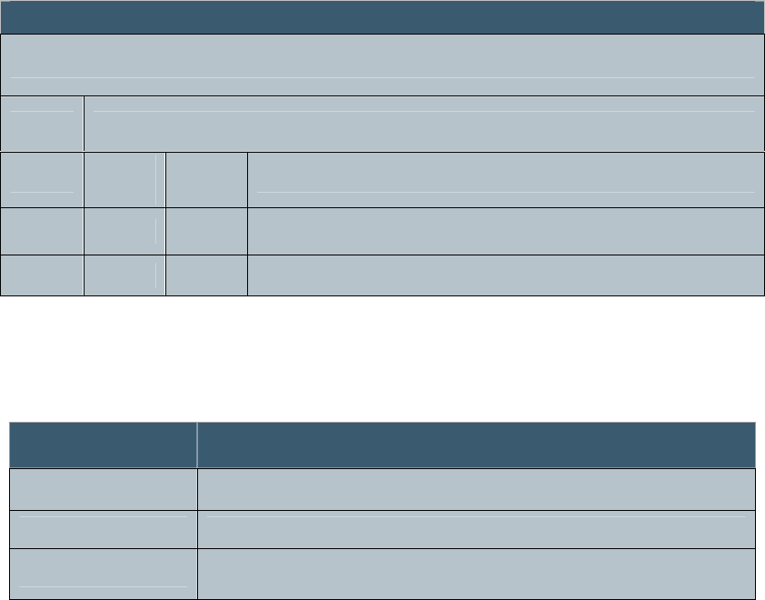
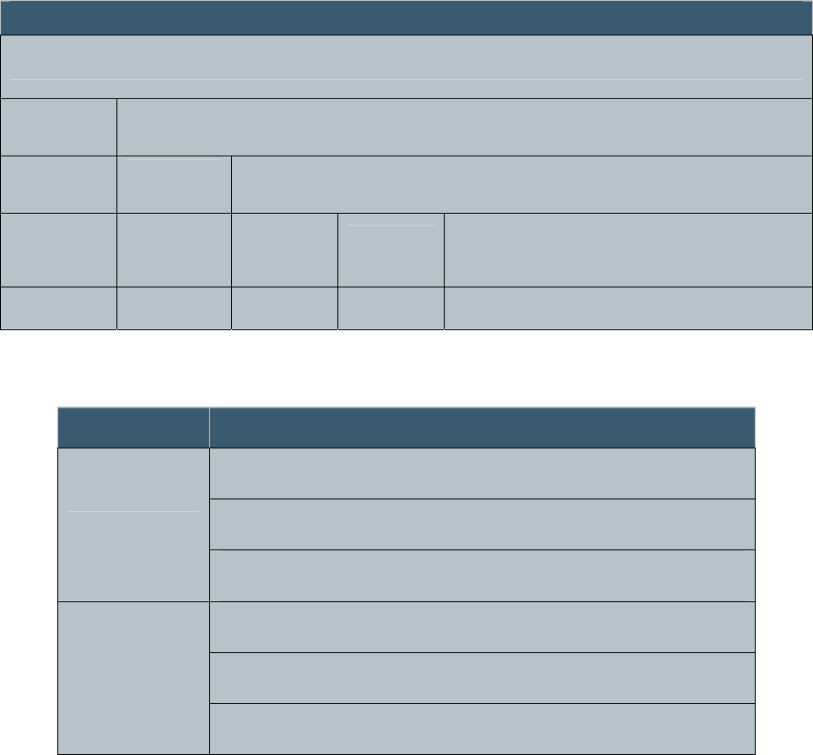
4.6.10.1 ERASE ID Sub-Command Status Message
Once the tag has been erased a status message will be sent to
the host indicating the command execution result. A
STATUS_COMPLETE status message indicates the tag was
erased successfully. Otherwise, an error status message is sent
indicating any of the following error conditions upon erasing a
tag:
ERR_ERASE_ID_FAIL
ERR_TAG_READ_FAIL
Figure 38 ERASE_ID Sub-Command Status Message
Table 35 ERASE_ID Sub-Command Status Field Definitions
MSB LSB
Message
Status Response
Status
Code
0x00
1 byte 127 bytes
Field Definition
STATUS CODE This field should be set to
STATUS_COMPLETE
ERR_ERASE_ID_FAIL This field will return a 0xE9
ERR_TAG_READ_FAIL This field will return a 0xEA

December 6, 2006 Proprietary Information 52
Revision 1.0
4.7 Class 1 Generation 2 Commands
The following section describes the command messages used
to support Class 1 Generation 2 tags. Class 1 Generation 2 tags
may be read and written. The Command Code 0x04 is for
TAG_2 (Class 1 Generation 2) tag commands.
Figure 39 Class 1 Generation 2 Command Format
MSB LSB
Message
Command
Code Parameters
0x04 Sub-Command
Code Parameters
1 byte 1 byte 1-126 bytes

December 6, 2006 Proprietary Information 53
Revision 1.0
4.7.1 Class 1 Generation 2 Sub-Commands
The Class 1 Generation 2 command utilizes sub-commands and
parameters in the following manner.
Table 36 Class 1 Generation 2 Sub-Commands
Sub-Command Code Description Return
Status
Message
KILL 0xFF Kill a Class 1 Generation 2 tag Yes
SET 0x00 This command is used to set the RF power
level and modulation depth. Yes
READ 0x01 Read Class 1 Generation 2 tags Yes
PROGRAM 0x02 All Class 1 Generation 2 tags receiving this
command will program the specified tag id
in memory. Yes
LOCK 0x03 This command prevents any further
modification of the data stored on the tag Yes
December 6, 2006 Proprietary Information 54
Revision 1.0
4.7.2 KILL Sub-Command
The KILL sub-command is used to render tags non-
operational. The KILL sub-command contains the following
message format:
Figure 40 KILL Sub-Command Message Format
Table 37 KILL Sub-Command Field Definitions
Field Definition
Q Value Q Value for interrogation session with tags
Tag ID Bit Count This field should be set to the number of bits in the tag id
Kill Password The KILL password that is programmed onto the tag to be
killed
TAG_ID This is the Tag ID bits to be used in addressing a single tag
that is to be killed
MSB LSB
Message
Command Parameters
Sub-
Command
Parameters
0x04 0xFF Q value Tag ID Bit
Count Kill
Password Tag ID
1 byte 1 byte 1 bytes 1 byte 4 bytes 32 bytes 88 bytes

December 6, 2006 Proprietary Information 55
Revision 1.0
4.7.2.1 KILL Sub-Command Status Message
The KILL sub-command status message contains the following
message format:
Figure 41 KILL Sub-Command Status Message Format
Table 38 KILL Sub-Command Status Field Definitions
Field Definition
STATUS This field should be set to STATUS_COMPLETE
TAG_COUNT Number of tags killed (0x0000 or more, MSB first)
MSB LSB
Message
Status Response
Status
Code Tag Count
0x00
1 byte 2 bytes 126 bytes
December 6, 2006 Proprietary Information 56
Revision 1.0
4.7.3 SET Sub-Command
The SET sub-command contains the following message
format:
Figure 42 SET Sub-Command Message Format
Table 39 SET Sub-Command Field Definitions
MSB LSB
Message
Command Parameters
Sub-
Command Parameters
0x04 0x00 RF Level Mod
Depth
1 byte 1 byte 1 byte 1 byte 124 bytes
Field Definition
RF power level to be used for reading Class 1 Generation 2
tags
NO_CHG (0x00) - The current RF setting is to remain
unchanged
RF_LEVEL
Setting (0x01 . . . 0x10) - +15 dBm to +30 dBm in 16 steps
of 1 dB
Modulation depth to be used for reading Class 1 Generation
2 tags
NO_CHG (0x00) - The current RF setting is to remain
unchanged
MOD_DEPTH
Setting (0x01 . . . 0x20) – 20 % to 95 % in steps of ~2.42 %

December 6, 2006 Proprietary Information 57
Revision 1.0
4.7.3.1 SET Sub-Command Status Message
The SET sub-command status message contains the following
command message format:
Figure 43 SET Sub-Command Status Message Format
Table 40 SET Sub-Command Status Field Definitions
Field Definition
STATUS CODE This field should be set to ERR_NONE
RF_LEVEL This is the Forward Power A/D target value for
power control
MOD_DEPTH This is the current Modulation Depth setting
MSB LSB
Message
Status Response
RF
level Mod
Depth
0x00
1 byte 1 byte 1 byte 125 bytes
December 6, 2006 Proprietary Information 58
Revision 1.0
4.7.4 READ Sub-Command
The READ sub-command is used to read tags. The READ
sub-command contains the following message format:
Figure 44 READ Sub-Command Message Format
Table 41 READ Sub-Command Field Definitions
Field Definition
Q Value Q Value for interrogation session with tags
FILTER_BIT_COUNT Number of filter bits to follow (0..96). Filter bit
count of 0 indicates no filter bits.
FILTER_BITS Holding filter bits, based on Filter_Bit_Count
MSB LSB
Message
Command Parameters
Sub-
Command
Parameters
0x04 0x01 Q value Filter Bit
Count Filter_Bits
1 byte 1 byte 1 byte 1 byte 32 bytes 92 bytes

December 6, 2006 Proprietary Information 59
Revision 1.0
4.7.4.1 READ Sub-Command Status Message
Figure 45 READ Sub-Command Status Message Format
Table 42 READ Sub-Command Status Field Definitions
Field Definition
STATUS
CODE This field should be set to IN_PROGRESS
TAG_COUNT The number of tags reported in this message
Tag ID Length
- Tag ID
A sequence of 1 or more tag lengths combined with tag IDs. The first
byte will contain the length of the tag ID that follows, whether 64 or 96
bit (0x40 or 0x60), and the bytes that follow will contain the Tag ID up
to the length specified in the first byte. Subsequent tag IDs will follow
this same pattern.
If any tags are singulated and read, this command will return
multiple messages. After all tags have been reported, the
reader will send a final summary message to the host.
MSB LSB
Message
Status Response
Status
Code Tag
Count Tag ID Length - Tag ID
0x01
1 byte 1 byte 126 bytes

December 6, 2006 Proprietary Information 60
Revision 1.0
4.7.4.2 READ Sub-Command Summary Status Message
After all tags have been reported, the reader will send a final
summary status message to the host.
Figure 46 READ Sub-Command Summary Status Message Format
Table 43 READ Sub-Command Summary Status Message Field Definitions
Field Definition
STATUS CODE This field should be set to
STATUS_COMPLETE
TOTAL_TAG_COUNT Total number of tags reported
MSB LSB
Message
Status Response
Status
Code
Total
Tag
Count
0x00
1 byte 2 bytes 125 bytes
December 6, 2006 Proprietary Information 61
Revision 1.0
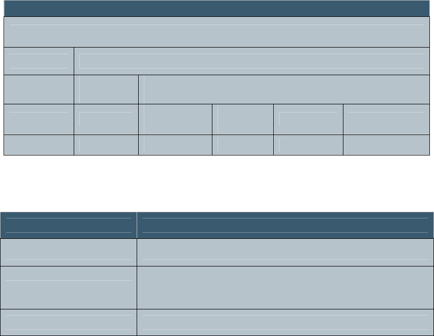
4.7.5 PROGRAM Sub-Command
The PROGRAM sub-command is used to program an EPC ID
into a Class 1 generation 2 tag. The PROGRAM sub-
command contains the following message format:
Figure 47 PROGRAM Sub-Command Message Format
Table 44 PROGRAM Sub-Command Field Definitions
Field Definition
Q Value Q Value for interrogation session with tags
Tag ID Bit Count This field should be set to the number of bits in the tag id
Kill Password The KILL password to be programmed onto the tag to allow
it to be killed in the future
TAG_ID This is the Tag ID to be programmed into the tag
MSB LSB
Message
Command Parameters
Sub-
Command
Parameters
0x04 0x02 Q value Tag ID Bit
Count Kill
Password Tag ID
1 byte 1 byte 1 byte 1 byte 4 bytes 32 bytes 88 bytes
December 6, 2006 Proprietary Information 62
Revision 1.0
4.7.5.1 PROGRAM Sub-Command Status Message
The PROGRAM sub-command status message contains the
following message format:
Figure 48 PROGRAM Sub-Command Status Message Format
Table 45 PROGRAM Sub-Command Status Field Definitions
Field Definition
STATUS This field should be set to STATUS_COMPLETE
TAG_COUNT Number of tags programmed
MSB LSB
Message
Status Response
Status
Code Tag Count
0x00
1 byte 2 bytes 126 bytes
December 6, 2006 Proprietary Information 63
Revision 1.0
4.7.6 LOCK Sub-Command
The LOCK sub-command prevents further modification of the
EPC ID and the Kill password stored on a tag. The LOCK sub-
command contains the following message format:
Figure 49 LOCK Sub-Command Message Format
Table 46 LOCK Sub-Command Field Definitions
Field Definition
Q Value Q Value for interrogation session with tags
Tag ID Bit Count This field holds the number of bits in the tag id
TAG_ID This is the ID of the tag to be locked
MSB LSB
Message
Command Parameters
Sub-
Command
Parameters
0x04 0x03 Q value Tag ID Bit
Count Tag ID
1 byte 1 byte 1 byte 1 byte 32 bytes 92 bytes

December 6, 2006 Proprietary Information 64
Revision 1.0
4.7.6.1 C1G2 LOCK Sub-Command Status Message
Figure 50 LOCK Sub-Command Status Message Format
Table 47 LOCK Sub-Command Status Field Definitions
Field Definition
STATUS
CODE This field should be set to STATUS_COMPLETE
TAG_COUNT The number of tags locked
MSB LSB
Message
Status Response
Status
Code Tag
Count
0x00
1 byte 1 byte 126 bytes

December 6, 2006 Proprietary Information 65
Revision 1.0
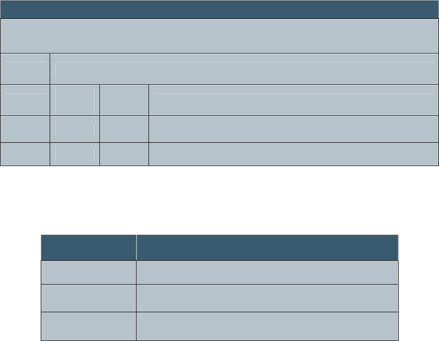
5.0 Troubleshooting
This section is intended to help you identify and correct
some common problems that can occur. For additional
information or assistance with any query, please call
SIRIT at 1-877-492-0101, ext. 2550.
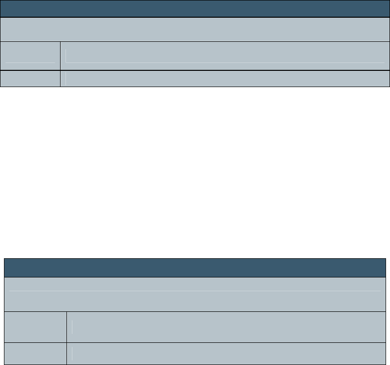
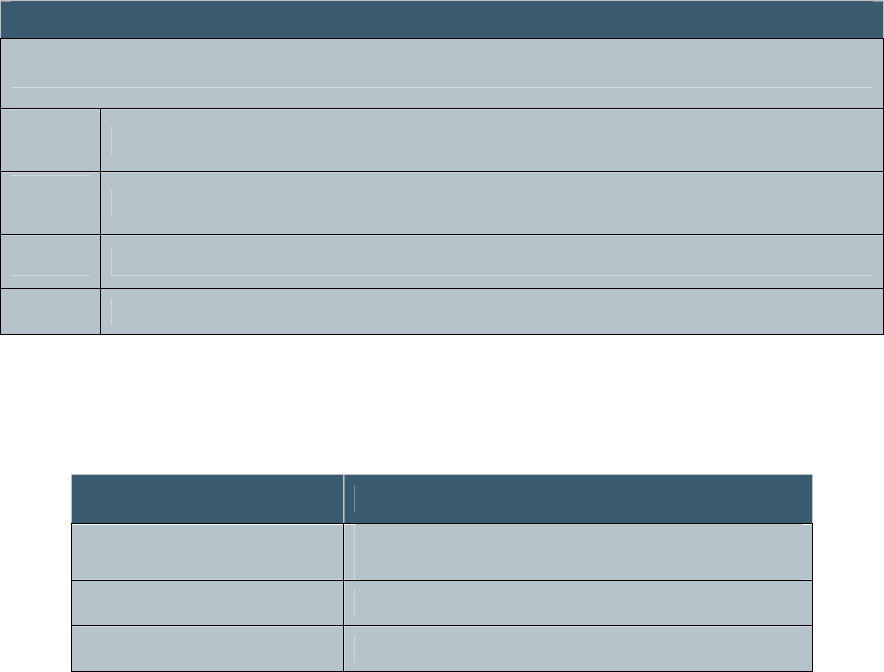
No Response from Reader
Checklist Solution
Check that the external power supply is
plugged into a 120 VAC 60 Hz outlet
Check physical connection to serial port of
the Host PC
Check that serial communications
parameters are correct (115200bps, 8 data
bits, no parity, 1 stop bit)
Check that serial commands are properly
constructed
Correct voltage problem.
Correct any connection issue at serial
interface connector.
Correct settings of serial communications
port.
Correct commands to conform to serial
protocol as specified in Section 4

December 6, 2006 Proprietary Information 66
Revision 1.0
Tags Will Not Read
Checklist Solution
Check that the external power supply is
plugged into a 120 VAC 60 Hz outlet
Check for proper reader response to
commands
Check reader response to serial
commands for error codes
Check serial command to reader for
proper command
Check for working tags in read zone
Check tag environment
Correct voltage problem.
If reader does not respond per serial
protocol as specified in Section 4,
perform “No Response”
troubleshooting.
If Status field of reader response is
“FF”, look up error code in Response
field in section 4
Correct command (i.e., Make sure to
use Class 0 read command for Class 0
tags).
Make sure tags are functional, and
making contact with the top of the
reader.
UHF tags will not function well in some
environments, such as in close
proximity to metal.

December 6, 2006 Proprietary Information 67
Revision 1.0
Intermittent Tag Reads
Checklist Solution
Check for working tags in read zone
Check tag environment
Make sure tags are functional, and in contact
with the top of the reader.
UHF tags will not function well in some
environments, such as in close proximity to
metal.
December 6, 2006 Proprietary Information 68
Revision 1.0
Appendix A CRC Calculation
This section shows how to calculate the CCITT CRC-16 over
the entire body of the message. The CCITT CRC-16 is
calculated starting with the LENGTH byte and continuing
through the length -2. The final two CRC bytes are not
included in the calculation but should be checked against the
CCITT CRC-16 for a match.
A typical command string, the Notify Command, with this
CRC Calculated follows:
01 05 00 00 27 6C
Where the 01 is the SOF byte, the 05 is the length and 00 00 is
the command for the Notify Command with the 276C as the
correctly calculated CRC.
Here is a “C” language listing that shows the CCITT CRC-16
calculation.
// ***************************************************************************************************
//
// CRC_Calc
// Calculates CCITT-CRC for IDentity MaX Desktop RFID reader
//
// Version 1.0
//
// This routine calculates the two byte CCITT-CRC for command and data messages for the IDentity MaX Desktop reader UHF
RFID
// Reader.
//
// Inputs: Place the entire message to be transmitted including SOH and two empty bytes for CRC into an array.
// In this demo case CommandArray and the total length of the command in the length variable, CommandLength
// are passed. These are passed into "bytearray[]" and "arraylength" variables of the routine.
//
// Outputs: This routine will return the value of the two-byte CRC which is calculated in the variable "crc".
//
// The routine begins with array index [1], and goes to array length -2. You will have to move the two bytes returned
// into the last two bytes of the array before transmitting the command. You can also use it to verify received
// commands by checking the entire length, i.e. set your length to two more than the actual length of the command. If
// the returned, the CRC is "0000" then the command is valid
//
// ****************************************************************************************************
#include <stdio.h>
#include <stdlib.h>
unsigned short CRC_Calc(char bytearray[256],int arraylength)
{
unsigned short crc = 0xFFFF; // Preload to FFFF
unsigned short tempresults; // Just a temporary results holder
unsigned short bitindex; // 0 - 7
unsigned short byteindex; // The byte pointer into the byte
// array that holds
December 6, 2006 Proprietary Information 69
Revision 1.0
// the command to be checked.
unsigned char placeholder; // A place to put the byte while we
// work on it.
for (byteindex = 1; byteindex <= (arraylength - 3); byteindex++) // begin checking after SOH and
// before CRC bytes
{
placeholder = bytearray[byteindex];
for(bitindex = 0; bitindex <= 7; bitindex++)
{
tempresults = (crc >> 15) ^ (placeholder >> 7); // Shift CRC right 15 bits then do a
// bitwise XOR
crc <<= 1; // Shift CRC left one bit and store it
// in CRC
if(tempresults)
{
crc ^= 0x1021;
// Standard CCITT Polynomial
// X16+X12+X5+1
}
placeholder <<= 1;
}
}
return crc; // Returns the CRC calculated in
// the variable crc
}