3M Traffic Safety Systems IN110 INfinity 110 HF RFID Reader User Manual
3M Traffic Safety Systems INfinity 110 HF RFID Reader
User Manual

INfinity 110 Evaluation Kit
U
SER’S
G
UIDE
V1.0
July 20, 2009
© Copyright 2009 Sirit, Inc. All Rights Reserved.
Disclaimer and Limitation of Liability
The content of this manual is for information use only and is subject to change without notice. Sirit assumes no responsibility or liability for
any errors or inaccuracies that may appear in this publication. No part of this manual may be reproduced in any form or by any means,
electronic, mechanical, recording, or otherwise, without the prior written permission of Sirit.
Sirit products are not designed, intended, authorized or warranted to be suitable for life support applications or any other life critical
applications which could involve potential risk of death, personal injury, property damage, or environmental damage.
About Sirit
Sirit Inc. designs, develops, manufactures and sells Radio Frequency Identification (RFID) technology. Targeted at a diverse set of markets
RFID technology has become a core technology for applications including: electronic toll collection, access control, cashless payment
systems, product identification, and supply chain management systems including logistics, warehousing and manufacturing, and asset
management.
Head Office - Canada
372 Bay Street, Suite 1100
Toronto, Ontario, M5H 2W9 Canada
Tel: 416.367.1897
Fax: 416.367.1435
Toll Free: 1.800.498.8760
Email: mail@sirit.com
Sirit, Inc. - US
1321 Valwood Parkway, Suite 620
Carrollton, Texas 75006 United States
Tel: 972.243.7208
Fax: 972.243.8034
Toll Free: 1.866.338.9586
Web: www.sirit.com

Preface
INfinity 110 Evaluation Kit
i
Preface
Intended audience
This document is intended for those who wish to use INfinity 110 Evaluation
Kit with the integrated INfinity 110 Reader. Before attempting to install,
configure, and operate this product, you should be familiar with the
following:
h Windows-based software installation and operation
h Device communication parameters and serial communications
h RFID reader configuration including antenna placement and RF
h Basic digital input/output control
What’s in this guide
Evaluation Kit Overview – This chapter provides a brief overview of the
INfinity 110 Evaluation Kit hardware and software.
Evaluation Kit Connections – This chapter describes how to mechanically
and electrically install the Evaluation Kit.
Smart Label Communicator (SLC) Software Installation – This chapter
describes how to install the Microsoft Windows SLC application.
Operation – This chapter provides basic instructions for basic operation
with the SLC application.
SLC – This chapter describes the SLC Graphical User Interface (GUI) and the
various functions you can perform with this Microsoft Windows application.
Configuration and Maintenance – This chapter provides information for
configuring the Evaluation Kit. For detailed command information, refer to
the INfinity 110 Protocol Reference Guide.
Troubleshooting – This chapter provides tips for troubleshooting the
Evaluation kit.
Specifications – This chapter detailed mechanical, electrical, and
environmental specifications for the Evaluation Kit.
Safety Instructions – This chapter provides important safety information
about the Evaluation Kit. All users must read this section before installing or
operating this Evaluation Kit.

Preface
ii
INfinity 110 Evaluation Kit
What’s New in this Version
Version 1.0 of this User’s Guide is the initial release.
Conventions used in this manual
The following conventions are used in this manual:
Bold courier font indicates code entered by the user
(values) within parentheses indicate parameters
(values)
in italics indicate user defined variables.
<n> indicates a variable number used in a function that can apply to
several different devices such as antennas or I/O ports.
WARNING:
Warnings advise the user that a hazardous condition can be created by a
particular action that can cause bodily injury or extreme damage to equipment
Caution:
Cautions advise the user that a condition can be created by a particular action
that can cause equipment damage or result in equipment operation that violates
regulatory requirements.
NOTES
Important information
and other tips are
presented in light
blue boxes to the left
of the applicable
section.

Contents
INfinity 110 Evaluation Kit
iii
Table of Contents
Evaluation Kit Overview ...............................................................................................................................1
Evaluation Kit .......................................................................................................................................2
Evaluation Kit Software........................................................................................................................3
Evaluation Kit Connections .........................................................................................................................4
Electrical Installation.............................................................................................................................4
Connecting Serial Communications......................................................................................................4
Connecting the Antenna........................................................................................................................4
Connecting the Power ...........................................................................................................................4
Smart Label Communicator (SLC) Software Installation .......................................................................5
SLC Installation.....................................................................................................................................5
Lotis Downloader Installation...............................................................................................................6
Operation .......................................................................................................................................................9
Basic Operation.....................................................................................................................................9
Determine the Read Range..................................................................................................................11
Read Digital Inputs/Outputs................................................................................................................12
SLC Application .......................................................................................................................................... 13
Tag-it ...................................................................................................................................................14
I-CODE ...............................................................................................................................................15
Inside ...................................................................................................................................................16
EPC/UID .............................................................................................................................................17
ISO14443A..........................................................................................................................................18
ISO14443B..........................................................................................................................................19
ISO15693 ............................................................................................................................................20
Communicator.....................................................................................................................................21
Configuration and Maintenance.............................................................................................................. 22
Setting the Baud Rate..........................................................................................................................22
Configuring the Digital I/O.................................................................................................................22
Downloading Firmware.......................................................................................................................22
Selecting The Communications Port...............................................................................................23
Selecting the Firmware File and Downloading...............................................................................23
Forcing the Reader into Bootloader Mode......................................................................................24
Troubleshooting ......................................................................................................................................... 25
Contents
iv
INfinity 110 Evaluation Kit
Specifications ............................................................................................................................................. 26
Evaluation Kit Specifications..............................................................................................................26
Environmental Specifications .............................................................................................................26
Power Supply Specifications...............................................................................................................26
Serial Communications Specifications ...............................................................................................27
Regulatory and Safety Instructions......................................................................................................... 28
RF Safety.............................................................................................................................................28
Regulatory Compliance.......................................................................................................................28

1
2 3 4 5 6 7 8 9
Evaluation Kit Overview
INfinity 110 Evaluation Kit
1
Evaluation Kit Overview
The INfinity 110 Evaluation Kit
contains a compact multi-protocol
Radio Frequency Identification
(RFID) reader operating in 13.56
MHz High Frequency (HF) band
along with interface board, antenna,
and power supply. The Evaluation
Kit supports multiple tag protocols
and is compatible with numerous
global standards. This product is
compliant to FCC Part 15 and ETSI
EN300-330 specifications.
Specific features of INfinity 110 Evaluation kit include:
h Read-from and write-to most leading 13.56 MHz transponders
h Secure firmware download capability via the serial interface
h Accepts firmware updates to support future tags
h Configurable baud rate
h Configurable start-up speed
h Single 9 VDC power supply operation
h Two user input lines and two user output lines
The INfinity 110 Evaluation Kit supports the following protocols:
h ISO 15693
h ISO 14443 A & B
h ISO 18000-3 Mode 1
h Inside PicoTag™
h NXP EPC
h NXP UID
h NXP I-CODE
h NXP Mifare Ultralite
h TI-RFID™ Tag-it™
1
2 3 4 5 6 7 8 9
Evaluation Kit Overview
2
INfinity 110 Evaluation Kit
Evaluation Kit
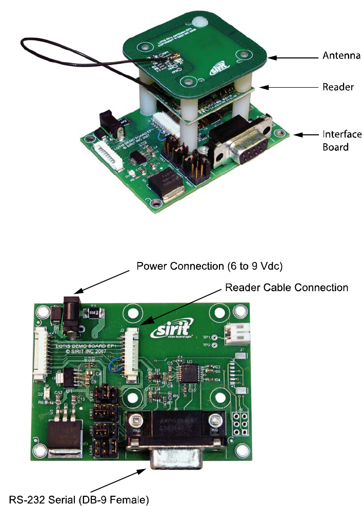
The INfinity 110 Evaluation Kit (PN IN110K-001) consists of a INfinity 110
Reader, Interface Board, antenna, power supply and cabling.
Figure 1
INfinity 110 Evaluation Kit (provided AC/DC Power Supply not shown)
Figure 2
INfinity 110 Evaluation Kit Interface Board
1
2 3 4 5 6 7 8 9
Evaluation Kit Overview
INfinity 110 Evaluation Kit
3
Evaluation Kit Software
The Evaluation Kit is shipped with a software program called Smart Label
Communicator (SLC) that can be installed on a host computer. With SLC,
you can perform the following:
h Select a tag protocol
h Read and write tags
h Perform a tag read test
h Read digital inputs
h Write digital outputs
h Set output attenuation (in dB)
h Turn carrier off
h Read version and serial number

1
2
3 4 5 6 7 8 9
Evaluation Kit Connections
4
INfinity 110 Evaluation Kit
Evaluation Kit Connections
Electrical Installation
Connect the power supply to the 2.1 mm power connector on the interface
board. The power supply should provide 6V to 9V at 400 mA.
Connecting Serial Communications
The Evaluation Kit is equipped with one TTL serial port for communication
up to 115200 Baud. If TTL-level serial communications is required, connect
the Transmit (Tx) line to pin 6 and the Receive (Rx) line to pin 8.
Connecting the Antenna
The Evaluation Kit is equipped with one Hirose U.FL socket (J1) for
connecting the provided antenna. This connector (Hirose U.FL) is not
commonly available and deters connecting any antenna not designed for
this Evaluation kit. Alternatively, a 2-pin 0.1”-pitch header can be installed
into the J2 position.
The antenna must be tuned to resonance at 13.56 MHz and should provide
a 50 Ohm load (nominal) at this frequency. A return loss of -20dB or greater
is preferred for reliable operation. The loaded Q of the antenna should be
10 to 25 for normal operation.
Connecting the Power
When the Evaluation kit powers up, LED D1 will briefly illuminate. After a
fraction of a second, LED D1 will extinguish and LED D2 will illuminate. This
indicates that power is present, the Evaluation Kit has successfully
performed its self-checks, and is ready to accept commands.
If a power supply is capable of monitoring current, a draw of about 45mA
should be observed (when operating via the interface board).
1 2
3
4 5 6 7 8 9
SLC Software Installation
INfinity 110 Evaluation Kit
5
Smart Label Communicator (SLC) Software Installation
SLC Installation
The Evaluation Kit is delivered with a Microsoft Windows application called
Smart Label Communicator (SLC). This application can be used to read tags
and perform other functions.
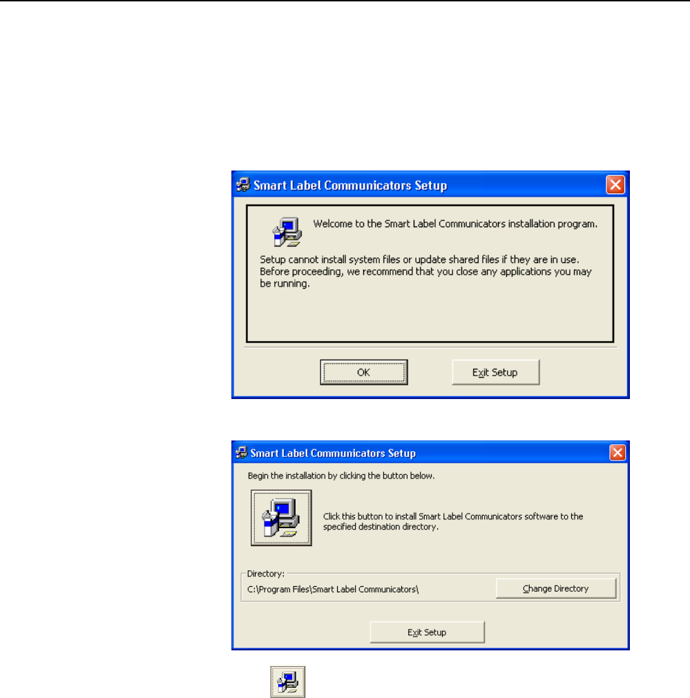
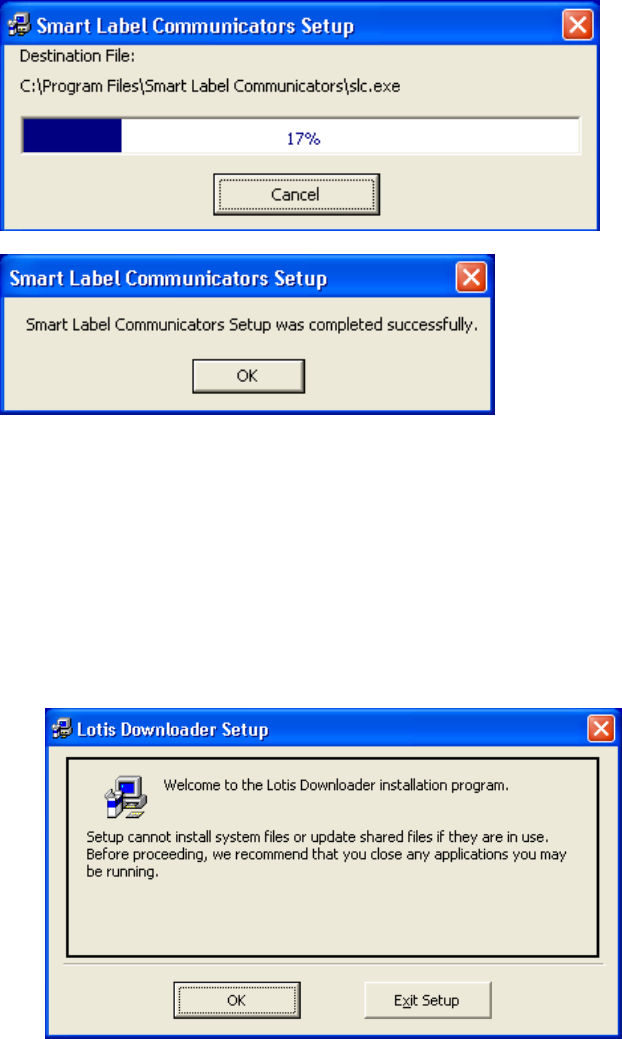
1 To install SLC, load the CD and double-click the Setup.exe file:
2 Verify no other applications are running and press
OK
.
3 Press to start the installation.
1 2
3
4 5 6 7 8 9
SLC Software Installation
6
INfinity 110 Evaluation Kit
4 Press OK to exit.
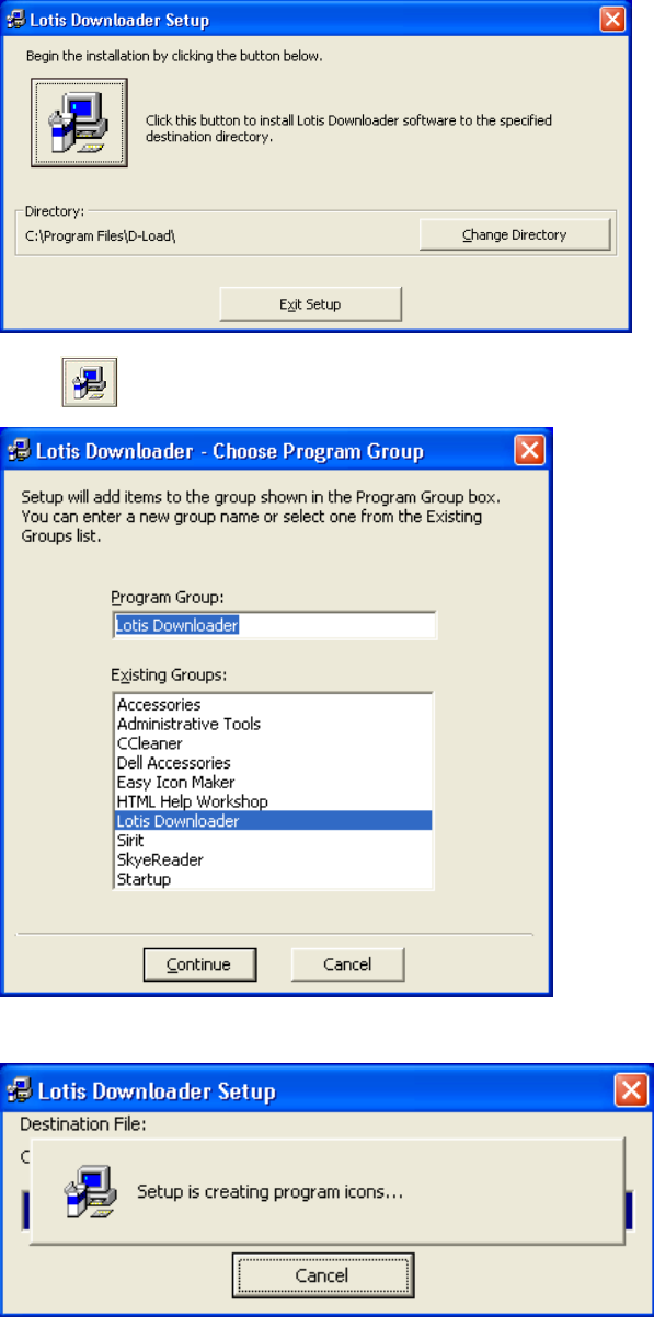
Lotis Downloader Installation
Lotis Downloader is used to download firmware updates for the Evaluation
Kit. To install Lotis Downloader, perform the following:
1 To install Lotis Downloader, navigate to the Lotis Downloader folder
and double-click the Setup.exe file:
2 Verify no other applications are running and press
OK
.
1 2
3
4 5 6 7 8 9
SLC Software Installation
INfinity 110 Evaluation Kit
7
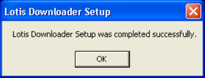
3 Press to start the installation.
4 Press
Continue.
1 2
3
4 5 6 7 8 9
SLC Software Installation
8
INfinity 110 Evaluation Kit
5 Press OK to exit.
1 2 3
4
5 6 7 8 9
Operation
INfinity 110 Evaluation Kit
9
Operation
Basic Operation
The Evaluation Kit can be operated from the SLC application or by
interfacing to a host computer and sending commands. This chapter
provides a brief description of how to operate the Evaluation Kit using SLC.
Connect and Power up the Evaluation Kit
1 Connect the serial cable from the Interface Board to the serial port
(COM1, etc.) on your computer.
2 Power up the Evaluation kit.
Open SLC
3 From your Windows desktop, select:
Start
→
Programs
→
Smart Label Communicators
→
Smart Label Communicators
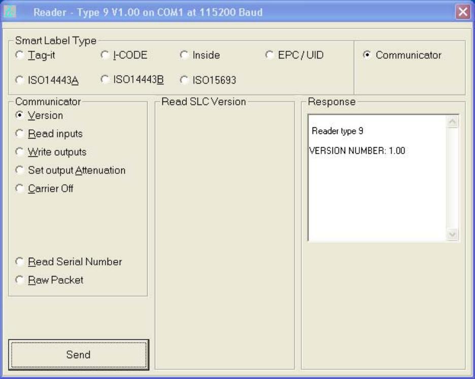
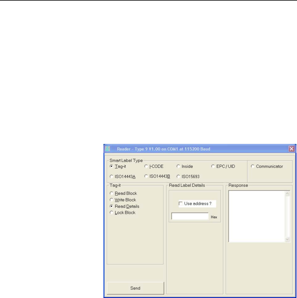
4 If the reader is communicating the following message is displayed
across the top of the display.
Reader – Type 9, V1.00 on COM1 at 115200 Baud
1 2 3
4
5 6 7 8 9
Operation
10
INfinity 110 Evaluation Kit
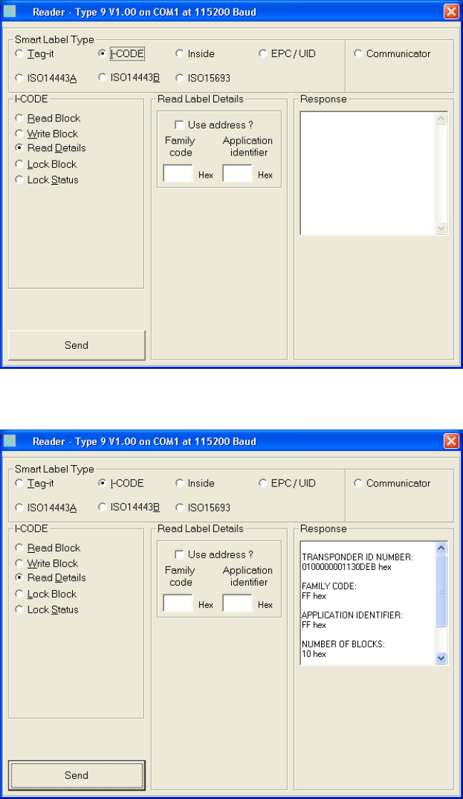
Read Tags
5 Select the appropriate protocol (for example, I-CODE).
6 Place a tag on top of the antenna.
7 Select Read Details and press Send.
1 2 3
4
5 6 7 8 9
Operation
INfinity 110 Evaluation Kit
11
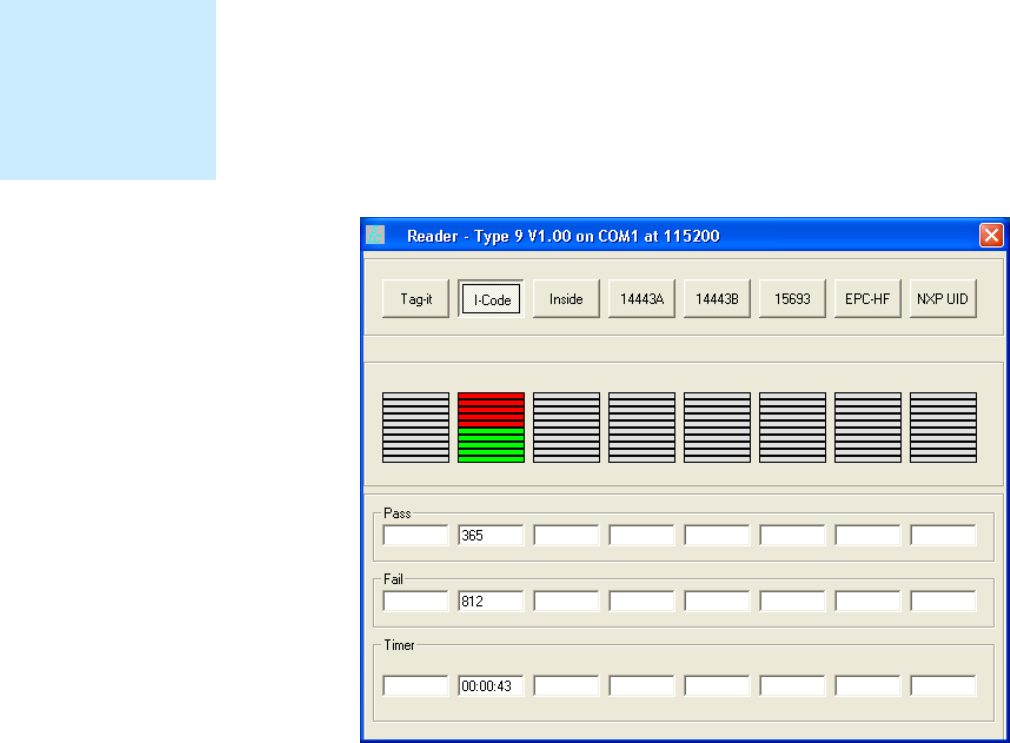
Determine the Read Range
The read range of a specific tag can easily be determined on the Evaluation
Kit using the Reader Test function built into the SLC application. To test the
read range perform the following:
1 Start SLC.
2 From the menu bar select:
Options
→
Reader Test
3 Select the appropriate protocol. The reader will attempt to the read a
tag. If no tag is present the bar graph will turn red and the Fail counter
will increment.
4 Place a tag over the antenna and slowly move it within range. The bar
graph will turn green and the Pass counter will increment.
5 Slowly move the tag away from the antenna and note the distance
where the bar graph turns back to red.
Read Range
Read range depends
on certain factors
such as tag protocol,
form factor, and
antenna geometry.

1 2 3
4
5 6 7 8 9
Operation
12
INfinity 110 Evaluation Kit
Read Digital Inputs/Outputs
Digital Inputs and Outputs are provided on the Interface Board via pins 2 to
5. Outputs are open collector and inputs are protected to 30 V.
Table 1 Evaluation Kit Digital Inputs and Outputs
Pin Signal Description
2 OP2 Open Collector Output 2
3 OP1 Open Collector Output 1
4 IP2 Input 2 (Max 30V)
5 IP1 Input 1 (Max 30V)
The Read Inputs command (0xF1) reads the logical states of the two digital
inputs. The states are returned as the least significant bits of the single
data byte of the response packet. Bit 0 indicates the logical state of Input 1,
with bit 1 indicating the logical state of Input 2.
The Write Outputs command (0xF2) sets the logical state of two open-
collector outputs.
For more information on setting the digital outputs and detecting the state
of the digital inputs, please refer to the INfinity 110 Protocol Reference
Guide.

1 2 3 4
5
6 7 8 9
SLC Application
INfinity 110 Evaluation Kit
13
SLC Application
The SLC software application provides a simple user interface for reading
various tags and configuring the Evaluation Kit. Functions provided by SLC
include:
h Automatically detect a reader
h Automatically determine the baud rate
h Select a tag protocol
h Read and write tags
h Perform a tag read test
h Read digital inputs
h Write digital outputs
h Set output attenuation (in dB)
h Turn carrier off
h Read version and serial number
SLC provides several different screens or pages for reading and writing
different tag protocols. These pages include:
h Tag-it
h I-CODE
h Inside
h EPC/UID
h ISO14443A
h ISO14443B
h ISO15693
1 2 3 4
5
6 7 8 9
SLC Application
14
INfinity 110 Evaluation Kit
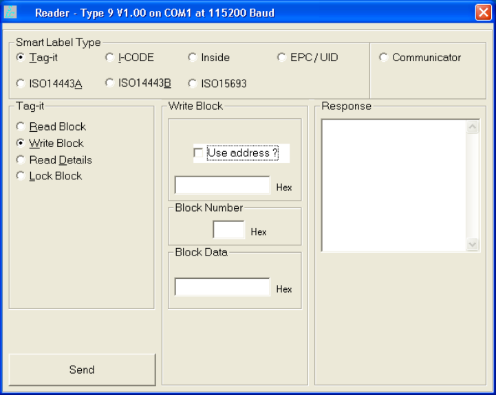
Tag-it
The
Tag-it
page allows you to read and write TI-RFID™ Tag-it™ protocol tags.
1 2 3 4
5
6 7 8 9
SLC Application
INfinity 110 Evaluation Kit
15
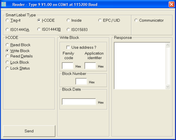
I-CODE
The
I-CODE
page allows you to read and write NXP I-CODE protocol tags.
1 2 3 4
5
6 7 8 9
SLC Application
16
INfinity 110 Evaluation Kit
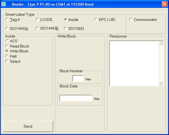
Inside
The
Inside
page allows you to read and write Inside PicoTag™ protocol tags.
1 2 3 4
5
6 7 8 9
SLC Application
INfinity 110 Evaluation Kit
17
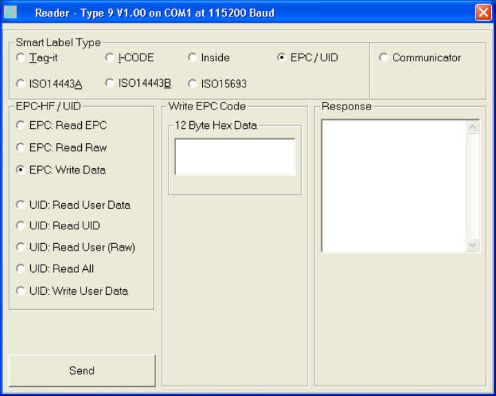
EPC/UID
The
EPC/UID
page allows you to read and write NXP EPC and NXP UID
protocol tags.
1 2 3 4
5
6 7 8 9
SLC Application
18
INfinity 110 Evaluation Kit
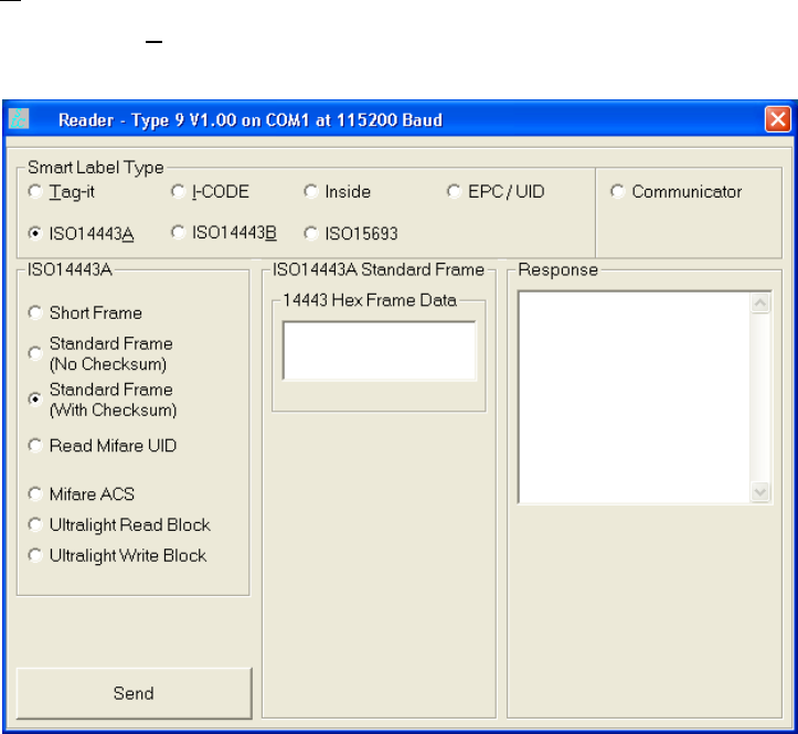
ISO14443A
The
ISO14443A
page allows you to read and write ISO 14443-A and NXP
Mifare Ultralite protocol tags.
1 2 3 4
5
6 7 8 9
SLC Application
INfinity 110 Evaluation Kit
19
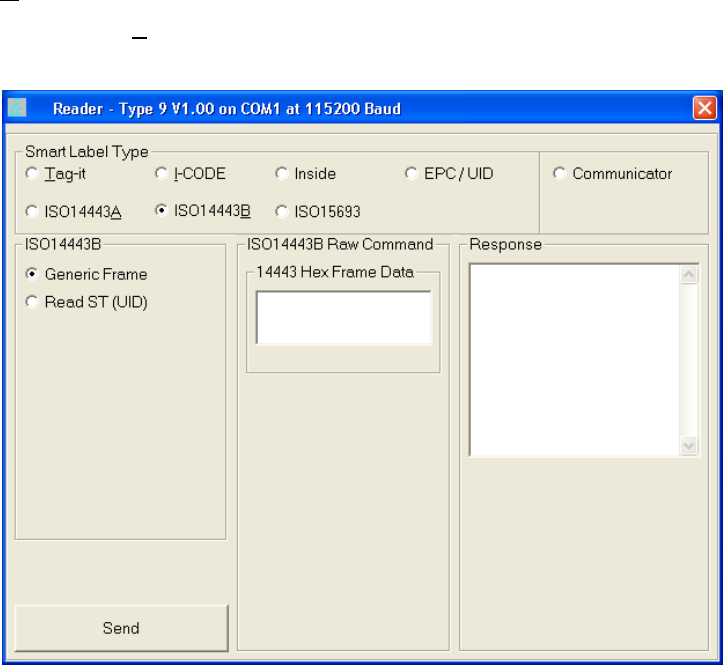
ISO14443B
The
ISO14443B
page allows you to read and write ISO 14443-B protocol
tags.
1 2 3 4
5
6 7 8 9
SLC Application
20
INfinity 110 Evaluation Kit
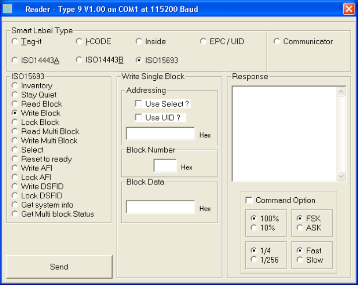
ISO15693
The
ISO15693
page allows you to read and write ISO 15693 protocol tags.

1 2 3 4
5
6 7 8 9
SLC Application
INfinity 110 Evaluation Kit
21
Communicator
The Communicator screen allows you to perform the following functions:
h Read firmware version
h Read digital inputs
h Write digital outputs
h Set output attenuation
h Turn carrier off
h Read serial number
h Send a raw packet

1 2 3 4 5
6
7 8 9
Configuration and Maintenance
22
INfinity 110 Evaluation Kit
Configuration and Maintenance
This chapter provides information for configuring the Evaluation Kit. For
detailed information on the INfinity 110 command and control protocol,
refer to the INfinity 110 Protocol Reference Guide.
Setting the Baud Rate
The Evaluation Kit may be configured to operate at one of five Baud rates.
These can be configured via the serial command set (refer to the SLC
protocol document for more information).
The Evaluation Kit is capable of supporting the following Baud rates:-
h 115,200
h 57,600
h 38,400
h 19,200
h 9,600
Unless specifically documented, the firmware Baud rate is factory set to
115,200 Baud.
Configuring the Digital I/O
Digital I/O is provided on the Evaluation Kit via pins 2 to 5. Outputs (pins 2
and 3) are open collector and inputs (pins 4 and 5) are protected to 30V.
For details of setting the digital outputs and detecting the state of the digital
inputs, please refer to the SLC protocol document for more information).
Downloading Firmware
The Evaluation Kit supports the downloading of firmware updates to flash
memory via the serial interface. Firmware updates may be provided for this
product for regular maintenance, support for new tags and feature
enhancements. Note that firmware download files cannot be created and
downloaded by the user.
To use the secure download facility, you will need the Lotis Downloader.exe
program, along with a copy of the latest firmware release.
To install the firmware downloader, execute the setup.exe file located in the
firmware downloader bundle. Follow the on-screen prompts, which will
guide you through the installation of the software.
1 2 3 4 5
6
7 8 9
Configuration and Maintenance
INfinity 110 Evaluation Kit
23
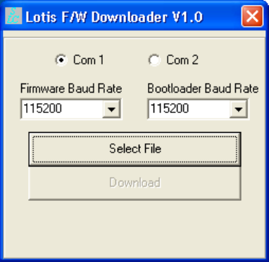
Once completed, the
Lotis Downloader icon will be available in a Lotis
Downloader folder on the Windows Start Menu. Upon selecting this icon, you
will be presented with the following interface.
Selecting The Communications Port
Both the Firmware Baud Rate and Bootloader Baud Rate parameters
should be set to the Baud rate of the board. Typically these will both be
115200.
Selecting the Firmware File and Downloading
Pressing the Select File button will enable selection of the firmware (.fmw)
file. Navigate to the folder containing the firmware file you wish to
download, select the filename from the file list and press the OK button.
If the load was successful, the Download button will now be enabled.
Pressing this button will initiate the download process. A blue progress bar
will show the status of the download.
During the download process, LED D2 will extinguish and LED D1 will
illuminate. This indicates that the reader is in bootloader mode. D2 will
blink to indicate each successful transaction between the host and the
Evaluation Kit.
Once the download process is complete LED D1 will extinguish and LED D2
will illuminate.
1 2 3 4 5
6
7 8 9
Configuration and Maintenance
24
INfinity 110 Evaluation Kit
Forcing the Reader into Bootloader Mode
If the reader becomes locked and will not automatically enter bootloader
mode (the download software does not work), activating the bootloader link
mechanism will force the reader into bootloader mode when powered. To
apply the bootloader link mechanism, perform the following:
1 Ensure the Evaluation Kit is powered down.
2 Short the LINK pin (pin 10) to GND (pin 1) on J3.
3 Power-up the Evaluation Kit.
4 Remove the link.
LED D1 should be on and LED D2 should be off to indicate that the
Evaluation Kit is running in bootloader mode.

1 2 3 4 5 6
7
8 9
Troubleshooting
INfinity 110 Evaluation Kit
25
Troubleshooting
Problem Probable Cause Corrective Action
Incorrect serial communications
parameters.
Verify settings of serial communications
port (115200bps, 8 data bits, no parity, 1
stop bit)
No response from module
Incorrect serial commands
construction.
Correct commands to conform to serial
protocol as specified in INfinity 110
Protocol Reference Guide.
Incorrect serial command. Verify command (for example, use ISO
15593 command set for ISO 15693 tags).
No functional tags in read zone Verify tags are functional and within the
read range of the module.
Adverse tag environment HF tags will not function well in some
environments, such as areas with high
moisture content or in close proximity to
metal.
Tags will not read
Antenna not properly connected Attach antenna. Check the integrity of the
antenna connector.
No functional tags in read zone Verify tags are functional and within the
read range of the module.
Poor read range / Intermittent
tag reads
Adverse tag environment HF tags will not function well in some
environments, such as areas with high
moisture content or in close proximity to
metal.

1 2 3 4 5 6 7
8
9
Specifications
26
INfinity 110 Evaluation Kit
Specifications
Evaluation Kit Specifications
Frequency 13.56 MHz
RF Output Power 200 mW maximum
Antenna Type 50Ω (ohms)
Input Voltage 3.3 VDC, ±5%, ,50 mV ripple
Active Current 300 mA
Standby Current 60 mA
Idle/Sleep Current 40 mA
Communications 3.3V TTL-level serial
Environmental Specifications
Operating Temperature -20 ºC to +60 ºC (-4 ºF to 140 ºF)
Storage Temperature -40 ºC to +125 ºC (-40 ºF to 257 ºF)
Relative Humidity 10 to 80%, non-condensing
Dimensions 70 x 52 x 38 mm (2.75 x 2.03 x 1.50 in.)
Weight 52 g (1.84 oz.)
Mounting 4-corner mounting holes 3.18 mm dia (o.25 in)
Power Supply Specifications
Vendor Part No. EPS090166UH-P5P-SZ (0.4A) or EMS090200-P5P-SZ
(0.6A) with 2.1 mm, center positive plug
Input Voltage 100 to 240 VAC, 0.4A
Input Frequency 50–60 Hz
Output Voltage 9 VDC
Output Current 1.66A maximum

1 2 3 4 5 6 7
8
9
Specifications
INfinity 110 Evaluation Kit
27
Serial Communications Specifications
Type 3.3V TTL-level
Connector DB-9 (female on Interface Board)
Baud rate 9600 - 115200 (Default = 115200)
Parity None
Data bits 8
Stop bits 1
Signals
Pin 6
Pin 8
Serial TX (Asynchronous, 0 to 3.3 V TTL logic level data
output from module)
Serial Rx (Asynchronous, 0 to 3.3 V TTL logic level data input
to module)

1 2 3 4 5 6 7 8
9
Regulatory and Safety Instructions
28
INfinity 110 Evaluation Kit
Regulatory and Safety Instructions
RF Safety
Caution:
The INfinity 110 HF Reader is equipped with one (1) RF port.
To prevent reader damage, this RF port must be properly
terminated with a 50 ohm load or a functional HF antenna
before power up. Never power up the reader unless the
appropriate load or antenna is connected. Always power
down the reader before removing an antenna or load from
an RF port.
Regulatory Compliance
Caution:
This equipment complies with Part 15 of the FCC rules. Any
changes or modifications not expressly approved by the
manufacturer could void the user's authority to operate the
equipment.
Caution:
This device complies with Part 15 of the FCC rules subject to
the following two conditions:
1) This device may not cause harmful interference.
2) This device must accept all interference received,
including interference that may cause undesired
operation.
Sirit’s INfinity 110 Evaluation kit (IN110K-001) with 45 mm x 45 mm
antenna has passed FCC Part 15 regulatory requirements and was granted
FCC certification (FCC Identifier M4ZIN110). Any additional antenna
attached to the reader will need to be tested and certified by the
user/supplier. It is the responsibility of the user when the system
configuration is modified affecting Radio Frequency performance. The
following two antenna sizes were supplied for the FCC compliance testing
and complied within the radiated limits:
h Small Demo Antenna – This is the standard demo kit antenna known as
INfinity 11x RFID ANTENNA V1 that is illustrated in Figure 1. This has a
nominal resonant frequency of 13.56 MHz and an impedance of
50 Ohms at this frequency. The dimensions of this antenna are
1.77 in x 1.77 in (45 mm x 45 mm).
h Compact Disc Antenna – This antenna also has a nominal resonant
frequency of 13.56 MHz and an impedance of 50 Ohms at this
frequency. The dimensions of this larger antenna are 5.47" x 4.65"
(139 mm x 118 mm).
1 2 3 4 5 6 7 8
9
Safety Instructions
INfinity 110 Evaluation Kit
29

INfinity 110 User’s Guide