3e Technologies 527A3 Wireless Mesh Access Point/Bridge/Switch User Manual CERTIFICATE OF COMPLIANCE
3e Technologies International, Inc. Wireless Mesh Access Point/Bridge/Switch CERTIFICATE OF COMPLIANCE
User Manual

Rhein Tech Laboratories, Inc. Client: 3e Technologies Int’l
360 Herndon Parkway Model: 3e-527A3
Suite 1400 Standards: FCC 15.247 & RSS-210
ID’s: QVT-527A3/6780A-527A3 Herndon, VA 20170
http://www.rheintech.com Report #: 2006146
Page 81 of 114
Appendix K: User Manual
Please refer to the following pages.

ERRATA SHEET
Changes to 29000152-001 Revision C
Chapter 6, page 99, Paragraph titled “Radio Frequency Interference Requirements”
The text currently reads:
“This device has been tested and found to comply with the limits for a Class A Digital Device,
pursuant to Part 15 of the Federal Communications Commission’s Rules and Regulations.”
The text should read:
“This device has been tested and found to comply with the limits for a Class B Digital Device,
pursuant to Part 15 of the Federal Communications Commission’s Rules and Regulations.”
The following information should be appended to the “Radio Frequency Interference Requirements” section:
“Radiation Exposure Statement
This equipment shall only be installed and operated with the antenna types shown below, with
gains not more than those shown below for each of the antennas, respectively, and installed with a
minimum of 20 cm of separation distance between the antenna and all persons during normal
operation.
Per FCC 1.1310 Table 1B, the maximum permissible RF exposure for an uncontrolled
environment is 1 mW/cm2 for the frequencies used in this device. The worst case power at the
center frequency of the band of operation is used for the calculation below. The power density
at a 20 cm distance is shown for each of the antenna options. As shown, the calculated power
density is well below the FCC’s limit. The actual power density for the EUT calculated as
shown below.
where:
S = power density
P = transmitter conducted power in (mW)
G = antenna numeric gain
d = distance to radiation center (cm)
Frequency Antenna
Antenna
Max Gain
(dBi)
Numeric
Gain
Power
(mW)
Separation
Distance
(cm)
Power
Density
(mW/cm2)
2.4 GHz Dual Band Omni
Antenna with N Male
Connector 2.1 1.6 355 20 0.113
5725 - 5825 GHz Rubber Duck Omni
Antenna with N Male
Connector 3 2 372 20 0.148
29000152-100 Revision C Page 1 of 1
Wireless Access Point – 8 Port
User's Guide
Model 3e–527A3
3e Technologies International
700 King Farm Blvd., Suite 600
Rockville, MD 20850
(301) 670-6779 www.3eti.com
29000152-001 B publ. 1003/06
�
This page intentionally left blank.
3e Technologies International's
Wireless Access Point – 8 Port
User's Guide
Model 3e–527A3
29000152-001 B iii
Copyright © 2006 3e Technologies International, Inc. All rights reserved. No part of this
documentation may be reproduced in any form or by any means or to make any derivative work
(such as translation, transformation, or adaptation) without written permission from 3e Technologies
International.
3e Technologies International reserves the right to revise this documentation and to make changes in
content from time to time without obligation on the part of 3e Technologies International to provide
notication of such revision or change.
3e Technologies International provides this documentation without warranty, term or condition
of any kind, either implied or expressed, including, but not limited to, the implied warranties,
terms, or conditions of merchantability, satisfactory quality, and tness for a particular purpose.
3e Technologies International may make improvements or changes in the product(s) and/or the
program(s) described in this documentation at any time. Certain features listed may have restricted
availability and/or are subject to change without notice - please conrm material features when
placing orders.
If there is any software or removable media described in this documentation, it is furnished under a
license agreement included with the product as a separate document, in the printed documentation,
or on the removable media in a readable le such as license.txt or the like. If you are unable to locate a
copy of the license, contact 3e Technologies International and a copy will be provided to you.
___________________________________
UNITED STATES GOVERNMENT LEGEND
If you are a United States Government agency, then this documentation and the product described
herein are provided to you subject to the following:
All technical data and computer software are commercial in nature and developed solely at private
expense. Software is delivered as “Commercial Computer Software” as dened in DFARS 252.227-
7014 (June 1995) or as a “commercial item” as dened in FAR 2.101(a) and as such is provided with
only such rights as are provided in 3e Technologies International’s standard commercial license for
the software. Technical data is provided with limited rights only as provided in DFAR 252.227-7015
(Nov 1995) or FAR 52.227-14 (June 1987), whichever is applicable. You agree not to remove or deface
any portion of any legend provided on any licensed program or documentation contained in, or
delivered to you in conjunction with, this User Guide.
___________________________________
3e Technologies International and the 3e Technologies International logo are registered trademarks.
Windows is a registered trademark of Microsoft Corporation. Any other company and product name
mentioned herein is a trademark of the respective company with which they are associated.
EXPORT RESTRICTIONS
This product contains components, software, and/or rmware exported from the United States in
accordance with U. S. export administration regulations. Diversion contrary to U.S. law is prohibited.
29000152-001 B iii
Table of Contents
SAFETY INFORMATION ............................................................................................vi
Chapter 1: Introduction...................................................................................................1
Basic Features .............................................................................................................2
Wireless Basics............................................................................................................3
802.11b.......................................................................................................................3
802.11a .......................................................................................................................3
802.11g.......................................................................................................................3
802.11b/g Mixed......................................................................................................3
802.11a Turbo............................................................................................................4
Network Conguration ............................................................................................4
Access Point Congurations..................................................................................5
Possible AP Topologies.........................................................................................5
Bridging ....................................................................................................................6
Default Conguration.............................................................................................6
Data Encryption and Security................................................................................6
SSID ...........................................................................................................................6
AES and 3DES..........................................................................................................7
MAC Address Filtering ..........................................................................................7
DHCP Server............................................................................................................7
Operator Authentication and Management ........................................................7
Management...............................................................................................................8
Chapter 2: Hardware installation................................................................................11
Preparation for Use..................................................................................................11
Installation Instructions ..........................................................................................11
Minimum System and Component Requirements ............................................12
Connectors and Cabling .........................................................................................12
Earth Ground Connection....................................................................................13
The Indicator Lights..............................................................................................14
Chapter 3: Access Point Conguration ......................................................................15
Introduction ..............................................................................................................15
Preliminary Conguration Steps...........................................................................15
Initial Setup using the “Local” Port ......................................................................16
Login..........................................................................................................................17
System Conguration..............................................................................................18
General....................................................................................................................18
Operating Mode.....................................................................................................19
Submode...............................................................................................................19
Congure Wireless Cards ..................................................................................20
WAN........................................................................................................................21
LAN .........................................................................................................................22
Encrp Port...............................................................................................................23
Static AES Key .....................................................................................................24
Static 3DES Key ...................................................................................................25
Wireless Access Point Conguration ....................................................................26
General....................................................................................................................26
Security ...................................................................................................................29
Static AES Key .....................................................................................................29
Static 3DES Key ...................................................................................................30
Dynamic Key Exchange .....................................................................................31
FIPS 802.11i ..........................................................................................................32
MAC Address Filtering ........................................................................................33
iv 29000152-0001 B
29000152-001 B v
Rogue AP Detection ..............................................................................................34
Advanced................................................................................................................35
Wireless Bridge.........................................................................................................35
Services Settings.......................................................................................................36
DHCP Server..........................................................................................................36
Subnet Roaming.....................................................................................................37
SNMP Agent...........................................................................................................38
Admin User Management ......................................................................................40
List All Users..........................................................................................................40
Add New User .......................................................................................................41
User Password Policy ...........................................................................................42
End User Authentication ........................................................................................43
General....................................................................................................................43
User List..................................................................................................................44
Add New User .......................................................................................................45
Add Authenticated MAC.....................................................................................46
List Authenticated MAC ......................................................................................46
Monitoring/Reports................................................................................................47
System Status .........................................................................................................47
Bridging Status.......................................................................................................48
Bridge Site Map .....................................................................................................49
Wireless Clients......................................................................................................50
Adjacent AP List ....................................................................................................51
DHCP Client List...................................................................................................52
System Log .............................................................................................................52
Web Access Log .....................................................................................................53
Network Activity...................................................................................................54
Auditing ....................................................................................................................55
Log ...........................................................................................................................55
Report Query..........................................................................................................56
Conguration.........................................................................................................56
System Administration ...........................................................................................58
Email Notication Conguration .......................................................................58
Conguration-Button............................................................................................59
System Upgrade ....................................................................................................61
Firmware Upgrade..............................................................................................61
Local Conguration Upgrade ...........................................................................62
Remote Conguration Upgrade .......................................................................64
Factory Default ......................................................................................................66
Remote Logging.....................................................................................................67
Reboot .....................................................................................................................67
Utilities....................................................................................................................68
Chapter 4: Gateway Conguration .............................................................................69
Introduction ..............................................................................................................69
Conguring in Gateway Mode..............................................................................71
WAN........................................................................................................................72
Main IP Setting ....................................................................................................72
IP Aliasing ............................................................................................................73
LAN .........................................................................................................................74
Security ...................................................................................................................75
Firewall......................................................................................................................75
Content Filtering....................................................................................................75
IP Filtering ..............................................................................................................76
Port Filtering ..........................................................................................................76
iv 29000152-0001 B
29000152-001 B v
Virtual Server .........................................................................................................77
Demilitarized Zone (DMZ) ..................................................................................78
Advanced................................................................................................................79
Chapter 5: Wireless Bridge Conguration ................................................................81
Introduction ..............................................................................................................81
Wireless Bridge — General ..................................................................................82
Auto-forming Wireless Bridging ......................................................................82
Manual Bridging .................................................................................................84
Monitoring ...........................................................................................................85
Wireless Bridge — Radio......................................................................................85
Wireless Bridge — Encryption.............................................................................87
Wireless Bridge — MAC Address FIltering.......................................................88
Setting Up Bridging Type .......................................................................................89
Point-to-Point Bridge Conguration ..................................................................89
Point-to-Point Bridging Setup Guide - Manual Mode...................................90
Point-to-Point Bridging Setup Guide - Auto Mode .......................................90
Point-to-Multipoint Bridge Conguration ........................................................94
Point-to-Multipoint Bridging Setup Guide - Manual Mode.........................95
Point-to-Multipoint Bridging Setup Guide - Auto Mode..............................95
Repeater Bridge Conguration ...........................................................................96
Repeater Bridging Setup Guide - Manual Mode............................................96
Repeater Bridging Setup Guide - Auto Mode.................................................97
Chapter 6: Technical Support.......................................................................................99
Manufacturer’s Statement ......................................................................................99
Radio Frequency Interference Requirements.......................................................99
Glossary ........................................................................................................................G-a

vi 29000152-0001 B
SAFETY INFORMATION
Please follow thes guidelines when installing and using the 3e–527A3
product.
! WARNING
Warnings must be followed carefully to avoid
bodily injury.
! CAUTION
Cautions must be observed to avoid damage to
your equipment.
NOTE: Notes contain important information about this product.
3e–527A3 Wireless Access Point – 8 Port Chapter 1: Introduction
29000152-0001 B 1
Chapter 1: Introduction
This manual covers the installation and operation of the 3e Technolo-
gies International’s 3e–527A3 Wireless Access Point. The 3e–527A3 is a
ruggedized access point/gateway/bridge which is intended for use in
industrial and external environments. It accommodates 802.11a/b/g, and
802.11a Turbo WLAN access and uses Power over Ethernet (PoE) access
to the Ethernet WAN to eliminate the need for internal access point power
supply units (AC-DC converters) and 110-220V cabling installations. The
wireless LANs can include mobile devices such as handheld Personal
Data Assistants (PDAs), mobile web pads, and wireless laptops.
FIPS 140-2 mode is always on and encryption is applied for the
WLAN. You can set encryption for Static AES, Static 3DES, Dynamic Key
Exchange, or FIPS 802.11i.
The access point employs state-of-the-art AES or 3DES encryption,
wireless devices must have the 3e-010F, 3e-010F-A-2, or 3e-010F-C-2
Crypto Client software installed. (The 3e-010F Crypto Client software is
sold with the 3e-110 long range PC Card or sold separately for use with
other compatible PC Cards.)
The 3e–527A3 incorporates Power over Ethernet. The PoE interface
on the 3e–527A3 is compatible with commercial vendor “injected power”
hub units.
The 3e–527A3 includes AES/3DES cryptographic modules for wire-
less encryption and HTTPS/TLS, for secure web communication. The
3e–527A3 has an Ethernet WAN interface for communication to the wired
LAN backbone, Ethernet LAN local port for purposes of initial setup
and conguration, and one wireless AP antenna for communicating on
the 802.11b/g frequencies. An antenna for bridging uses the 802.11a and
802.11a Turbo frequencies. The AP and Bridging frequencies can also be
swapped using a software congurable feature. In other words the AP
can use 802.11a/Turbo A and the Bridge can use 802.11b/g.
3e–527A3 Wireless Access Point – 8 Port Chapter 1: Introduction
2 29000152-001 B
3e–527A3 Wireless Access Point – 8 Port Chapter 1: Introduction
29000152-0001 B 3
Basic Features
The 3e–527A3 is housed in a sturdy case which is not meant to be
opened except by an authorized technician for maintenance or repair.
If you wish to reset to factory settings, use the reset function available
through the web-screen management module.
The 3e–527A3 is wall-mountable.
It has the following features:
• Ethernet uplink WAN port
• Local Ethernet LAN port (for conguration only)
• Wireless Access Point with operating range of 2000+ feet
• Bridge
• Power over Ethernet (PoE)
• Above average temperature range for extreme environments
(with TEC option)
• AES, 3DES, DKE, or FIPS 802.11i, depending on setup
• HTTPS/TLS secure Web
• DHCP client
• Access Point or Gateway with Bridging also available in either
mode
• Bandwidth control
• Adjustable Radio Power
• MAC address ltering
• Publicly Secure Packet Forwarding
• Rogue AP Detection
• Encrypted Ethernet port
• Auto bridging/Mesh Networking
• Conguration File transfer
• IP aliasing on gateway mode
• Operates on Channels 149, 153, 157, 161 and 165
The following cryptographic modules have been implemented in the
3e–527A3 .
• AES (128/192/256 bit)
• 3DES (192 bit)
• DKE
• FIPS 802.11i
3e–527A3 Wireless Access Point – 8 Port Chapter 1: Introduction
2 29000152-001 B
3e–527A3 Wireless Access Point – 8 Port Chapter 1: Introduction
29000152-0001 B 3
Wireless Basics
Wireless networking uses electromagnetic radio frequency waves to
transmit and receive data. Communication occurs by establishing radio
links between the wireless access point and devices congured to be part
of the WLAN.
The 3e–527A3 incorporates 802.11a, the 802.11b (WiFi) standard, the
802.11g standard and the most state of the art encryption for a very pow-
erful and secure wireless environment.
802.11b
The IEEE 802.11b standard, developed by the Wireless Ethernet
Compatibility Alliance (WECA) and ratied by IEEE, establishes a stable
standard for compatibility. A user with an 802.11b product can use any
brand of access point with any other brand of client hardware that is built
to the 802.11b standard for basic interconnection. 802.11b devices provide
11 Mbps transmission (with a fallback to 5.5, 2 and 1 Mbps depending on
signal strength) in the 2.4 GHz band.
For wireless devices to communicate with the 3e–527A3 , they must
meet the following conditions:
• The wireless device and wireless access point must have been
congured to recognize each other using the SSID (a unique ID as-
signed in setup so that the wireless device is seen to be part of the
network by the 3e–527A3 );
• Encryption and authentication capabilities and types enabled
must conform; and
• If MAC ltering is used, the 3e–527A3 must be congured to
allow the wireless device’s MAC address to associate (communi-
cate) with the 3e–527A3 wireless interface.
802.11a
The IEEE 802.11a standard is an extension to 802.11 that applies to
wireless LANs and provides up to 54 Mbps in the 5GHz band. 802.11a
uses an orthogonal frequency division multiplexing encoding scheme
rather than FHSS or DSSS.
802.11g
Because 802.11g is backwards-compatible with 802.11b, it is a popular
component in LAN construction. 802.11g broadens 802.11b’s data rates
to 54 Mbps within the 2.4 GHz band using OFDM (orthogonal frequency
division multiplexing) technology.
802.11b/g Mixed
802.11b/g combines 802.11b and 802.11g data rates to offer a broader
range.
3e–527A3 Wireless Access Point – 8 Port Chapter 1: Introduction
4 29000152-001 B
3e–527A3 Wireless Access Point – 8 Port Chapter 1: Introduction
29000152-0001 B 5
802.11a Turbo
802.11a Turbo technology provides speed and throughput of more
than double standard wireless LAN technologies in networking products
such as PCs, access points, routers and PC cards. It is very helpful to users
who require additional bandwidth (over standard WLAN technologies)
that results in higher throughput necessary for a variety of functions such
as: streaming media (video, DVD, MPEG), VoIP, etc., or for providing
multiple users on a single WLAN with optimal speeds despite network
demand.
108 Mbps is the maximum link speed available and the typical MAXI-
MUM end-user throughput ranges from approximately 40 Mbps to 60+
Mbps, depending on application demand and network environment.
NOTE: Turbo A’s channel bonding feature can signicantly degrade
the performance of neighboring 802.11a channel WLANs that don’t use
Turbo A, because there isn’t enough room in the 5GHz wireless LAN
spectrum for the increased spectrum used by channel bonding. Moreover,
Turbo A doesn’t check to see if 11a standard-compliant devices are in
range before using its non-standard techniques.
The encryption must be applied in the 3e-527C, however, the CPU
power can not encrypt more than 12 Mpbs of data. Therefore, even in
turbo A mode, you will not see more than 12 Mbps of throughput. One
benet of Turbo A is that it provides better RF range.
Network Conguration
The 3e–527A3 is an access point/gateway with bridging capability:
• Access point/Gateway plus:
• Wireless bridging with choice of:
- Point-to-point setup
- Point-to-multipoint setup
- Repeater setup
Bridging actually has more choices, but the above choices are popular
and are discussed later in this user guide (Chapter 4).
3e–527A3 Wireless Access Point – 8 Port Chapter 1: Introduction
4 29000152-001 B
3e–527A3 Wireless Access Point – 8 Port Chapter 1: Introduction
29000152-0001 B 5
Access Point Congurations
When a 3e–527A3 is used as an access point, IP addresses for wire-
less devices are typically assigned by the wired network’s DHCP server.
The wired LAN’s DHCP server assigns addresses dynamically, and the
AP virtually connects wireless users to the wired network. All wireless
devices connected to the AP are congured on the same subnetwork as
the wired network interface and can be accessed by devices on the wired
network.
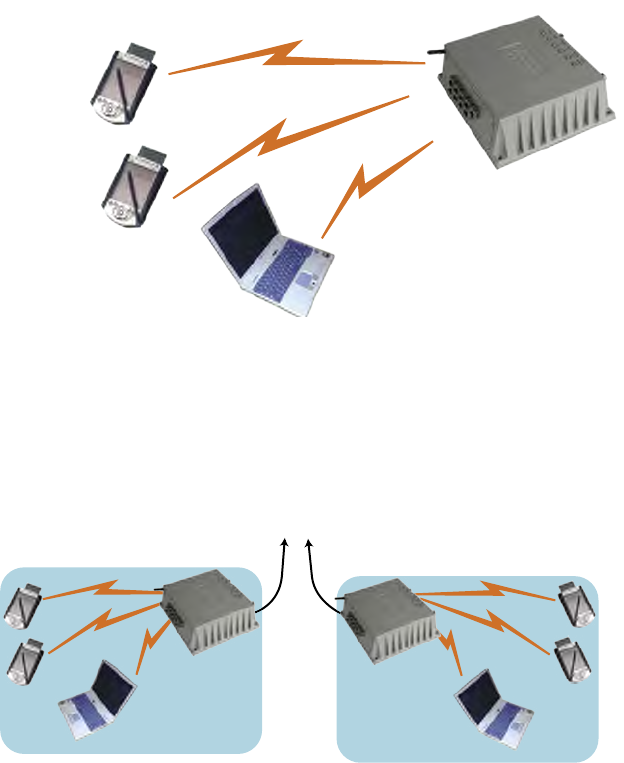
Possible AP Topologies
1. An access point can be used as a stand-alone AP without any
connection to a wired network. In this conguration, it simply
provides a stand-alone wireless network for a group of wireless
devices.
2. The 3e–527A3 can be used as one of a number of APs connected
to an existing Ethernet network to bridge between the wired and
wireless environments. Each AP can operate independently of
the other APs on the LAN. Multiple APs can coexist as separate
individual networks at the same site with a different network ID
(SSID).
3e–527A3 Wireless Access Point – 8 Port Chapter 1: Introduction
6 29000152-001 B
3e–527A3 Wireless Access Point – 8 Port Chapter 1: Introduction
29000152-0001 B 7
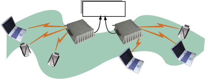
3. The last and most prevalent use is multiple APs connected to a
wired network and operating off that network’s DHCP server to
provide a wider coverage area for wireless devices, enabling the
devices to “roam” freely about the entire site. The APs have to use
the same SSID. This is the topology of choice today.
Bridging
The 3e–527A3 can also function as a bridge. There are a number of
briding congurations supported, including the following popular con-
gurations:
• Point-to-point bridging of 2 Ethernet Links;
• Point-to-multipoint bridging of several Ethernet links;
• Repeater mode (wireless client to wireless bridge.)
Default Conguration
The 3e–527A3's default conguration is an Access Point/Bridge with
FIPS 140-2 submode enabled.
Data Encryption and Security
The 3e–527A3 Wireless Access Point includes advanced wireless secu-
rity features. Over the AP band, you have a choice of AES, 3DES, or DKE.
Bridging encryption is established between 3e–527A3’s and includes use
of AES or 3DES encryption (approved by the National Institute of Stan-
dards and Technology (NIST) for U.S. Government and DoD agencies).
SSID
The Service Set ID (SSID) is a string used to dene a common roam-
ing domain among multiple wireless access points. Different SSIDs on
access points can enable overlapping wireless networks. The SSID can
act as a basic password without which the client cannot connect to the
network. However, this is easily overridden by allowing the wireless AP
to broadcast the SSID, which means any client can discover the AP. SSID
broadcasting can be disabled in the 3e–527A3 setup menus.
3e–527A3 Wireless Access Point – 8 Port Chapter 1: Introduction
6 29000152-001 B
3e–527A3 Wireless Access Point – 8 Port Chapter 1: Introduction
29000152-0001 B 7
AES and 3DES
The Advanced Encryption Standard (AES) was selected by National
Institute of Standards and Technology (NIST) in October 2000 as an up-
grade from the previous DES standard. AES uses a 128-bit block cipher
algorithm and encryption technique for protecting computerized infor-
mation. It has the ability to use even larger 192-bit and 256-bit keys, if
desired.
3DES is also incorporated on the 3e–527A3 . 3DES is modeled on the
older DES standard but encrypts data three times over. Triple-DES uses
more CPU resources than AES because of the triple encryption.
If you intend to use AES or 3DES, you must purchase the 3eTI ad-
vanced Crypto Client software (3e-010F, 3e-010F-A-2, or 3e-010F-C-2) for
each client that will be included in the WLAN. We sell the 3e-010F soft-
ware with the 3e-110 PC Card.
The 3e–527A3 uses AES-CCMP in WPA mode and AES-ECB (or 3DES)
for FIPS 140-2 mode and for bridging.
MAC Address Filtering
The MAC address, short for Media Access Control address, is a hard-
ware address that uniquely identies each node of a network. In IEEE 802
networks, the Data Link Control (DLC) layer of the OSI Reference Model
is divided into two sub-layers: the Logical Link Control (LLC) layer and the
Media Access Control (MAC) layer. The MAC layer interfaces directly with
the network media. Consequently, each type of network media requires a
unique MAC address.
Authentication is the process of proving a client's identity. The
3e–527A3 access points, if set up to use MAC address ltering, detect
an attempt to connect by a client and compare the client’s MAC address
to those on a predened MAC address lter list. Only client addresses
found on the list are allowed to associate. MAC addresses are pre-as-
signed by the manufacturer for each wireless card.
DHCP Server
The DHCP function is accessible only from the local LAN port to be
used for initial conguration.
Operator Authentication and Management
Authentication mechanisms are used to authenticate an operator ac-
cessing the device and to verify that the operator is authorized to assume
the requested role and perform services within that role.
Access to the management screens for the 3e–527A3 requires knowl-
edge of the assigned operator ID and Password. The Factory defaults are:
• ID: CryptoOfcer
• Password: CryptoFIPS
3e–527A3 Wireless Access Point – 8 Port Chapter 1: Introduction
8 29000152-001 B
3e–527A3 Wireless Access Point – 8 Port Chapter 1: Introduction
29000152-0001 B 9
The Crypto Ofcer initially installs and congures the 3e–527A3 after
which the password MUST be changed from the default password. The
ID and Password are case sensitive.
Management
After initial setup, maintenance of the system and programming of
security functions are performed by personnel trained in the procedure
using the embedded web-based management screens.
The next chapter covers the basic procedure for setting up the hard-
ware.

3e–527A3 Wireless Access Point – 8 Port Chapter 1: Introduction
8 29000152-001 B
3e–527A3 Wireless Access Point – 8 Port Chapter 1: Introduction
29000152-0001 B 9
3e-527A3 Navigation Options
Access Point/Bridge Mode Gateway/Bridge Mode
System Conguration System Conguration
General General
Operating Mode Operating Mode
WAN WAN
LAN LAN
Encrp Port Encrp Port
Wireless Access Point Wireless Access Point
General General
Security
• Static AES
• Static 3DES
• Dynamic Key Exchange
• FIPS 802.11i
Security
• Static AES
• Static 3DES
• Dynamic Key Exchange
• FIPS 802.11i
MAC Address Filtering MAC Address Filtering
Rogue AP Detection Rogue AP Detection
Advanced Advanced
Wireless Bridge Wireless Bridge
General
• Monitoring
General
• Monitoring
Radio Radio
Encryption Encryption
MAC Address Filtering (auto mode) MAC Address Filtering (auto mode)
Services Settings Services Settings
DHCP Server DHCP Server
Subnet Roaming Subnet Roaming
SNMP Agent SNMP Agent
Firewall Firewall
Content Filtering
IP Filtering
Port Filtering
Virtual Server
DMZ
Advanced
Admin User Management Admin User Management
List All Users
• Edit/Delete
List All Users
• Edit/Delete
Add New User Add New User
User Password Policy
End User Authentication End User Authentication
General General
List All Users List All Users
Add New User Add New User
Add Authed Mac Add Authed Mac
List Authed Mac List Authed Mac
Monitoring Reports Monitoring Reports
System Status System Status
Bridging Status Bridging Status
Bridging Site Map Bridging Site Map
Wireless Clients Wireless Clients
Adjacent AP List Adjacent AP List
DHCP Client List DHCP Client List
System Log System Log
Web Access Log Web Access Log
Network Activities Network Activities
Auditing Auditing
Log Log
Report Query Report Query
Conguration Conguration

3e–527A3 Wireless Access Point – 8 Port Chapter 1: Introduction
10 29000152-001 B
System Administration System Admnistration
Email Notication Conf Email Notication Conf
Conguration Button Conguration Button
System Upgrade
• Firmware Upgrade
• Local Conguration Upgrade
• Remote Conguration Upgrade
System Upgrade
• Firmware Upgrade
• Local Conguration Upgrade
• Remote Conguration Upgrade
Factory Default Factory Default
Remote Logging Remote Logging
Reboot Reboot
Utilities Utilities
3e–527A3 Wireless Access Point – 8 Port Chapter 2: Hardware Installation
29000152-001 B 11
Chapter 2: Hardware installation
Preparation for Use
The 3e Technologies International's 3e–527A3 Wireless Access Point
requires physical mounting and installation on the site, following a pre-
scribed placement design to ensure optimum operation and roaming.
FCC Regulations require that the 3e–527A3 be professionally in-
stalled by an installer certied by the National Association of Radio
and Telecommunications Engineers or equivalent institution.
The 3e–527A3 operates with Power over Ethernet (PoE) which re-
quires the installation of a separate Power injector which “injects” DC
current into the Cat5 cable. The standard version has a temperature range
of -5 degrees C to +65 degrees C.
The 3e–527A3 package includes the following items:
• The 3e–527A3 Wireless Access Point - 8 Port
• Qty 1 — omni-directional antenna (2.2dBi@2.4GHz and
5dBi@5.75GHz)
• Qty 1 — omni-directional antenna (3dBi@5.75GHz)
• 2 meter weather-resistant WAN Ethernet cable (RJ-45 to RJ-45)
• 3 meter standard LAN Ethernet Cable (RJ-45 to RJ-45)
• Documentation as PDF les (on CD-ROM)
• Registration and Warranty cards
The following items are options:
• Power Injector, POE, 50W (model 3e-POE-1, p/n 90000831-001)
• Power Cord, POE Injector, European version (p/n 90000832-001)
• Power Cord, POE Injector, UK version (p/n 90000833-001)
• Weather-resistant LAN Ethernet cables (RJ-45 to RJ-45)
Installation Instructions
The 3e–527A3 is intended to be installed as part of a complete wireless
design solution.
This manual deals only and specically with a single 3e–527A3 de-
vice as a unit. The purpose of this chapter is to describe the device and
its identiable parts so that the user is sufciently familiar to interact
with the physical unit. Preliminary setup information provided below
is intended for information and instruction of the wireless LAN system
administration personnel.
3e–527A3 Wireless Access Point – 8 Port Chapter 2: Hardware Installaton
12 29000152-001 B
3e–527A3 Wireless Access Point – 8 Port Chapter 2: Hardware Installation
29000152-001 B 13
It is intended that the user not open the unit. Any maintenance re-
quired is limited to the external enclosure surface, cable connections, and
to the management software (as described in chapter three through ve)
only. A failed unit should be returned to the manufacturer for mainte-
nance.
Minimum System and Component Requirements
The 3e–527A3 is designed to be attached to the wall at appropriate
locations. To complete the conguration, you should have at least the fol-
lowing components:
• PCs with one of the following operating systems installed: Win-
dows NT 4.0, Windows 2000 or Windows XP;
• A compatible 802.11b PC Card or 802.11b device for each comput-
er that you wish to wirelessly connect to your wireless network.
(For wireless cards, and praticularly if you will be using secure
FIPS mode with AES, we recommend that you select the 3e-110
PC Card with 3e-010F Crypto Client software (sold separately) or
install the 3e-010F-A-2 or 3e-010F-C-2 software;
• Access to at least one laptop or PC with an Ethernet card and
cable that can be used to complete the initial conguration of the
unit.
• A Web browser program (such as Microsoft Internet Explorer 5.5
or later, or Netscape 6.2 or later) installed on the PC or laptop you
will be using to congure the Access Point.
• TCP/IP Protocol (usually comes installed on any Windows PC.)
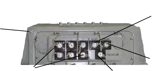
Connectors and Cabling
The following illustration shows the external connectors on the
3e–527A3.
LAN MGMT
Port
Ground
Mode Dependent
Gateway=LAN ports
AP=WAN ports
ENCRP Port
Wan Ethernet Port/
PoE/UPLINK
The PoE/UPLINK port is used to connect the 3e–527A3 to the organi-
zation's LAN. The Ethernet cable is run from the 3e–527A3 to the power
injector which is then connected to a power source and the wired LAN.
3e–527A3 Wireless Access Point – 8 Port Chapter 2: Hardware Installaton
12 29000152-001 B
3e–527A3 Wireless Access Point – 8 Port Chapter 2: Hardware Installation
29000152-001 B 13
A MGMT Port is designed for use during initial conguration only. This
uses an RJ45 cable to connect the 3e–527A3 to a laptop.
The ENCRP port is a dedicated Ethernet port used for connecting to
the Ethernet port of a DSL modem or any device that requires layer en-
cryption. This port is encrypted and is congureable for AES-128, 192, or
256 and also contains a message integrity check.
Ports X1-3 and Y1-3 are mode-dependent. If the 3e–527A3 is used as
an AP then those ports are WAN ports. If the unit is a gateway, then the
ports are LAN ports.
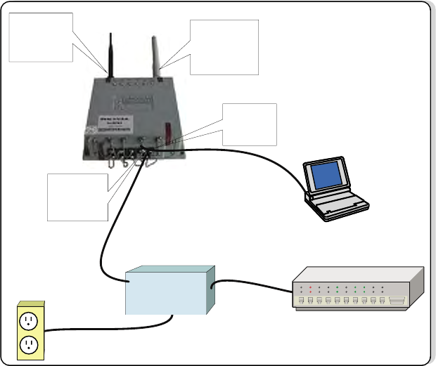
The following diagram demonstrates the setup.
Connect
802.11b/g
RF Antenna
(Black) for AP
Connect
802.11a RF
Antenna (Grey)
for Bridge
Power
Injector
110V
Power
Ethernet switch/hub
LAN Mgmt
Ethernet
Port
WAN
Ethernet
Port / PoE
Power
Injector
Earth Ground Connection
Attach the earth ground cable to the ring terminal attached to the
3e–527A3's grounding stud. Make sure the ring terminal is against the
unit's metal case. The earth ground ring terminal should be the rst con-
nection on the unit's grounding stud.
NOTE: The cable used to connect to a proper earth ground must be
AWG 10 or heavier. This cable should be kept as short as possible.

3e–527A3 Wireless Access Point – 8 Port Chapter 2: Hardware Installaton
14 29000152-001 B
The Indicator Lights
The top panel of the 3e–527A3 contains a set of indicator lights (Light
Emitting Diodes or LEDs) that help describe the state of various network-
ing and connection operations.
LED Description
Power The Power indicator LED indicates when the device is powered on. If
this light is on, the gateway is on; if it is not on, the gateway is off.
WAN This light indicates the state of your connection to the organization's
Ethernet LAN network. When on, the WAN light indicates that the
gateway is connected to the network. When the WAN light is off, the
gateway does not have an active connection to the network.
WLAN1
Activity
1. LED Off means the RF power is adminstratively disabled.
2. LED steady on means RF power is enabled but there no trafc.
3. LED blinking is relative to user trafc.
WLAN2
Activity
LED is used to indicate downlink trafc. It blinks when trafc is sent to
(or received from) the downlink.
• Root node: on and blinks with trafc.
• Intermediate node: on and blinks with trafc.
• Leaf node: always off.
WLAN Signal
Strength
The Strength LED indicator indicates the strength of the node assigned
in the Signal Strength MAC eld of the Bridge Conguration screen. If
there is no assignment, the strength of the uplink node is shown..
1. LED Off: means no connection on the bridge side, or the signal is
very weak.
2. LED blinks slowly (every 1 second): means there is a connection, and
the signal quality is poor.
3. LED blinks fast: means there is a connection, and the signal quality
is good.
4. LED steady on: means there is a connection, and the signal quality is
excellent.
FIPS/MODE
(WLAN2
Usage)
LED is used to indicate uplink trafc. It blinks when trafc is sent to (or
received from) the uplink.
• Root node: always off
• Intermediate node: on and blinks with trafc.
• Leaf node: on and blinks with trafc.
NOTE: for a standalone bridge, technically it’s root and leaf. But we
dene it as root, not leaf. So the WLAN 2 LED will be solid on. FIPS/
MODE LED will be off. When high bandwidth trafc is going through,
the response of the trafc LED indicators may be slow due to the work
load of the internal processor.
Power
WAN
WLAN 1
WLAN 2
WLANSS
FIPS/MODE
Detail of LEDs on the face of the 3e–527A3
3e–527A3 Wireless Access Point – 8 Port Chapter 3: Access Point Conguration
29000152-001 B 15
Chapter 3: Access Point Conguration
Introduction
The 3e–527A3 comes with the capability to be congured as an ac-
cess point. As it incorporates two separate 802.11 wireless cards, one for
conguring a local WLAN and one for use in bridging, it can also be
congured for bridging, either with access point or gateway conguration
on the WLAN side. Conguration as a gateway is discussed in Chapter 4
and conguration for bridging is discussed in Chapter 5.
Preliminary Conguration Steps
For preliminary installation the 3e–527A3 network administrator may
need the following information:
• IP address – a list of IP addresses available on the organization's
LAN that are available to be used for assignment to the AP(s)
• Subnet Mask for the LAN
• Default IP address of the 3e–527A3
• DNS IP address
• SSID – an ID number/letter string that you want to use in the con-
guration process to identify all members of the wireless LAN.
• The MAC addresses of all the wireless cards that will be used to
access the 3e–527A3 network of access points (if MAC address
ltering is to be enabled)
• The appropriate encryption key for Static 3DES or Static AES if
state-of-the art key management will be used.

3e–527A3 Wireless Access Point – 8 Port Chapter 3: Access Point Conguration
16 29000152-001 B
3e–527A3 Wireless Access Point – 8 Port Chapter 3: Access Point Conguration
29000152-001 B 17
Initial Setup using the “Local” Port
Plug one end of an RJ-45 Ethernet cable to the LAN port of the 3e–
527A3 (see page 11) and the other end to an Ethernet port on your lap-
top. This LAN port in the 3e–527A3 connects you to the device’s internal
DHCP server which will dynamically assign an IP address to your laptop
so you can access the device for conguration. In order to connect prop-
erly to the 3e–527A3 on the LAN port, the TCP/IP parameters on your
laptop must be set to “obtain IP address automatically.” (If you are unfa-
miliar with this procedure, use the following instructions for determining
or changing your TCP/IP settings.)
In Windows 98/Me click Start à Settings à Control Panel.
Find and double click the Network icon. In the Network window,
highlight the TCP/IP protocol for your LAN and click the Proper-
ties button. Make sure that the radio button for Obtain an IP address
automatically is checked.
In Windows 2000/XP, follow the path Start à Settings à Net-
work and Dialup Connections à Local Area Connection and select
the Properties button. In the Properties window, highlight the TCP/
IP protocol and click properties. Make sure that the radio button for
Obtain an IP address automatically is checked.
Once the DHCP server has recognized your laptop and has assigned a
dynamic IP address, you will need to nd that IP address. Again, the pro-
cedure is similar for Windows 95/98/Me machines and slightly different
for Windows 2000/XP machines.
In Windows 98/Me, click Start, then Run and type winipcfg in
the run instruction box. Then click OK. You will see the IP address of
your laptop in the resulting window, along with the “default gate-
way” IP address. Verify that the IP address shown is 192.168.15.x
In Windows 2000/XP, click Start, then Run and type cmd in the
run instruction box. Then click OK. This will bring up a window. In
this window, type ipcong /all |more. This will list information as-
signed to your laptop, including the IP address assigned. Verify that
the IP address shown is 192.168.15.x
3e–527A3 Wireless Access Point – 8 Port Chapter 3: Access Point Conguration
16 29000152-001 B
3e–527A3 Wireless Access Point – 8 Port Chapter 3: Access Point Conguration
29000152-001 B 17
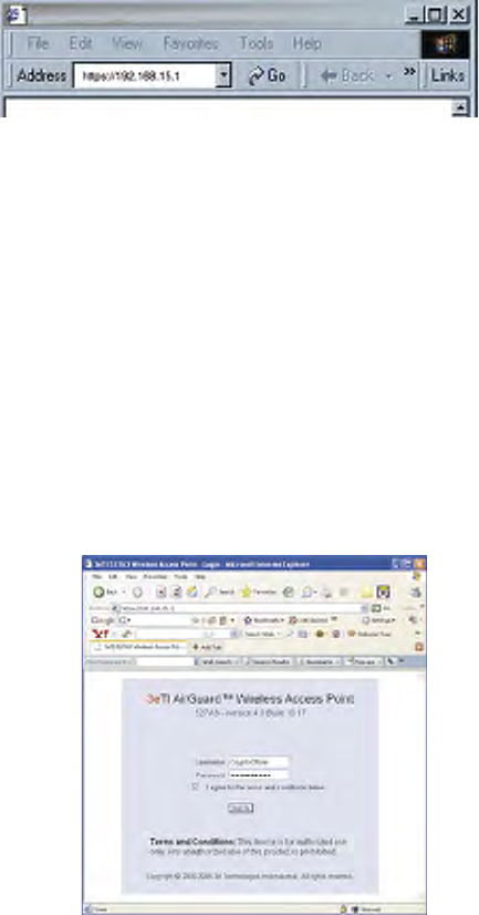
Login
On your computer, pull up a browser window and put the de-
fault URL for the 3e–527A3 Local LAN in the address line. (https://
192.168.15.1)
You will be asked for your User Name and Password. The default
is "CryptoOfcer" with the password "CryptoFIPS" to give full
access for setup conguration. (This password is case-sensitive.)
Please read the terms and conditions and check the checkbox then
click Sign In to continue conguration.
NOTE: The CryptoFIPS password is only good for the rst login. You
must change the password after initially logging in. You are automatically
directed to the Admin User Management—List All Users screen where
you must change your password. Click on Edit and enter your new pass-
word following the complexity password rule.
You are also asked to change your password every 30-90 days. If you
do not change your password then you will be locked out of the system
after 150 days.
NOTE: If your login session is in-active for more than 10 minutes,
then you will have to re-authenticate your identity. If after three times
you fail to re-authenticate then your account will be locked. The exception
is if you are the last active CryptoOfcer on the system, then your account
will not be locked. The Admin User Management—List All Users screen
displays account status. If an account is locked, it will show a status of
"Locked" and a reason of "bad passwd". Other accounts show status as
"Active" and reason "Normal".
The CryptoOfcer is the only user that can unlock an account once
it has been locked. Go to the Admin User Management—List All Users
screen and click the unlock button at the end of the user entry.
3e–527A3 Wireless Access Point – 8 Port Chapter 3: Access Point Conguration
18 29000152-001 B
3e–527A3 Wireless Access Point – 8 Port Chapter 3: Access Point Conguration
29000152-001 B 19
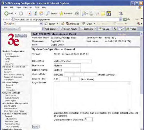
System Conguration
General
You will immediately be directed to the System Conguration —
General screen for the 3e–527A3 access point.
This screen lists the rmware version number for your 3e–527A3 and
allows you to set the Host Name and Domain Name as well as establish
system date and time. (Host and Domain Names are both set at the fac-
tory for “default” but can optionally be assigned a unique name for each.)
NOTE: The CryptoOfcer is the only user who can set the date and
time. The system date must be set to a date after 01/01/2005.
You can also enter a description of the physical location of the unit in
the Description eld. This is useful when deploying units to remote loca-
tions.
You can modify the terms and conditions login banner on the login
screen. The default is "This device is for authorized use only. Any unau-
thorized use of this product is prohibited."
When you are satised with your changes, click Apply.
Go next to the System Conguration — Operating Mode page.
3e–527A3 Wireless Access Point – 8 Port Chapter 3: Access Point Conguration
18 29000152-001 B
3e–527A3 Wireless Access Point – 8 Port Chapter 3: Access Point Conguration
29000152-001 B 19
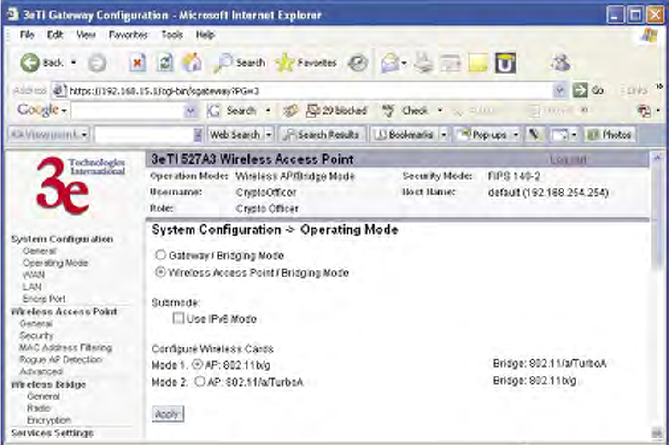
Operating Mode
This screen allows you to set the operating mode to either Wireless
Access Point/Bridge or Gateway/Bridge mode. You only need to visit
this page only if you will be changing from Access Point to Gateway
mode, if you want to change your submode to IPv6, or if you want to
congure the wireless cards.
Note that if you change modes from AP to Gateway, your congura-
tion is not lost. However, if you switch from IPv6 to non IPv6 submode,
all previously entered information will be reset to factory settings.
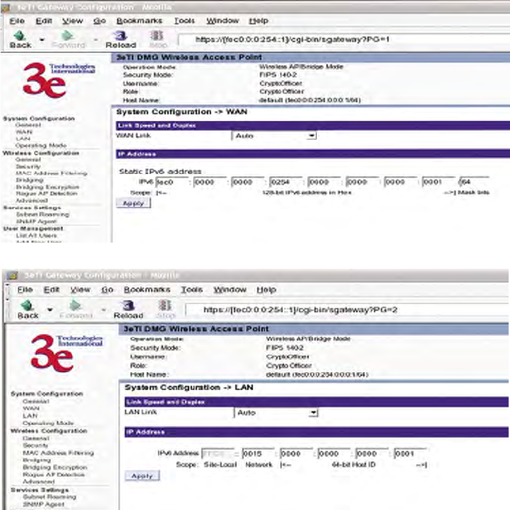
Submode
If you select the Use IPv6 Mode, the AP will be congured to support
IPv6 addresses on the WAN and LAN ports. In IPv6 mode, the AP can be
managed and pass trafc using IPv6 addresses. Since IPv6 is relatively
new in the industry, some networking functions that cannot support IPv6
are disabled such as DHCP server and WPA-802.1x
When in IPv6 mode, the AP can be accessed from the management
port using IP address 192.168.15.1. This is the default IP address and it
can not be changed. The WAN port can not be accessed using IPv4 ad-
dresses.
If Use IPv6 mode is selected as a submode then you will need to enter
a IPv6 address under System Conguration—WAN and LAN screens.
3e–527A3 Wireless Access Point – 8 Port Chapter 3: Access Point Conguration
20 29000152-001 B
3e–527A3 Wireless Access Point – 8 Port Chapter 3: Access Point Conguration
29000152-001 B 21
Congure Wireless Cards
The factory default for the two wireless cards are:
• 802.11b/g for the AP
• 802.11a/TurboA for the Bridge
If you want to swap the cards and make the 802.11a/TurboA card for
the AP and the 802.11b/g card for the Bridge. Select the appropriate but-
ton.
3e–527A3 Wireless Access Point – 8 Port Chapter 3: Access Point Conguration
20 29000152-001 B
3e–527A3 Wireless Access Point – 8 Port Chapter 3: Access Point Conguration
29000152-001 B 21
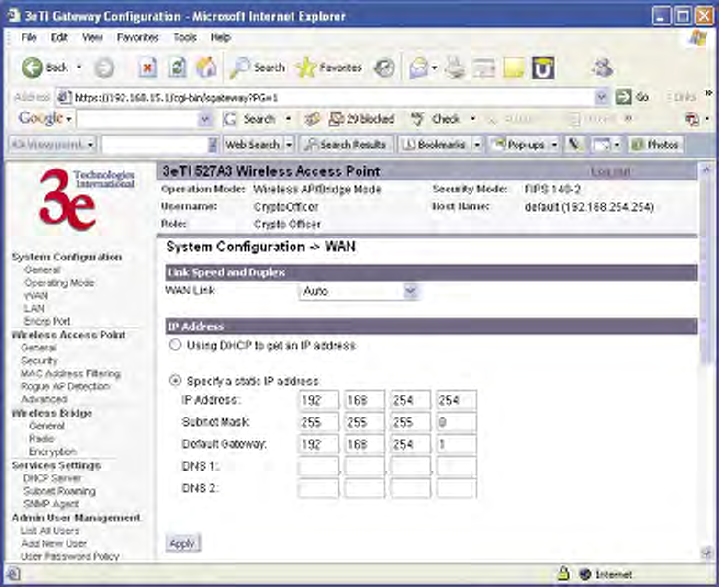
WAN
Click the entry on the left hand navigation panel for System Congu-
ration — WAN. This directs you to the System Conguration — WAN
screen.
If not using DHCP to get an IP address, input the static IP information
that the access point requires in order to be managed from the wired
LAN. This will be the IP address, Subnet Mask, Default Gateway, and,
where needed, DNS 1 and 2.
Click Apply to accept changes.
3e–527A3 Wireless Access Point – 8 Port Chapter 3: Access Point Conguration
22 29000152-001 B
3e–527A3 Wireless Access Point – 8 Port Chapter 3: Access Point Conguration
29000152-001 B 23
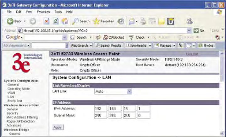
LAN
Click the entry on the left hand navigation panel for System Congu-
ration — LAN. This directs you to the System Conguration — LAN
screen.
This sets up the default numbers for the four octets for a possible pri-
vate LAN function for the access point. It also allows changing the default
numbers for the LAN Subnet Mask. The Local LAN port provides local
access for conguration. It is not advisable to change the private LAN ad-
dress while doing the initial setup as you are connected to that LAN.
3e–527A3 Wireless Access Point – 8 Port Chapter 3: Access Point Conguration
22 29000152-001 B
3e–527A3 Wireless Access Point – 8 Port Chapter 3: Access Point Conguration
29000152-001 B 23
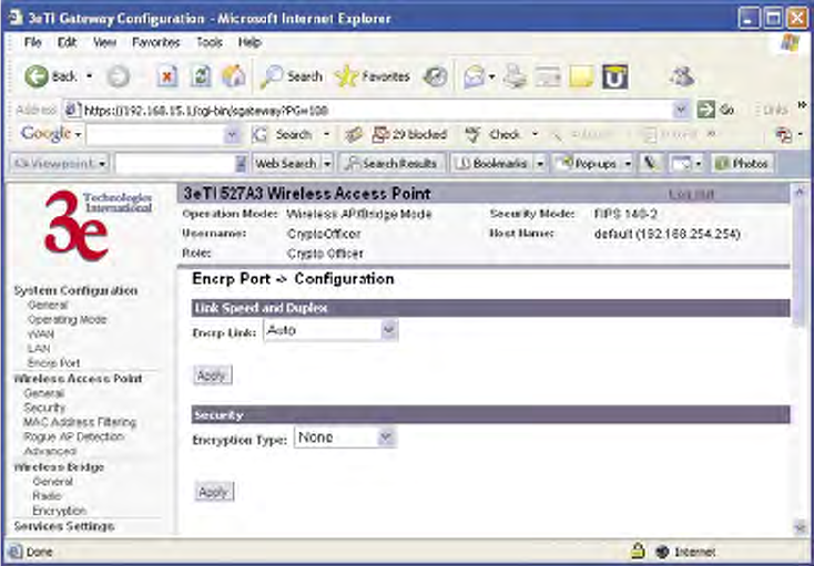
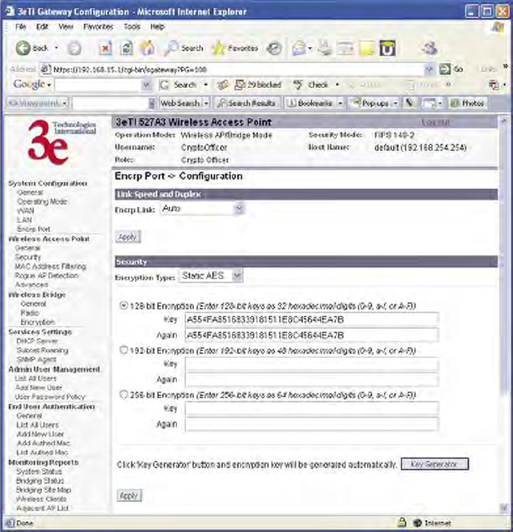
Encrp Port
Click the entry on the left hand navigation panel for System Con-
guration — Encrp Port. This directs you to the System Conguration
— Encrp Port screen.
You can set the link speed and duplex for the encrp port in the Encrp
Link eld. Your options are: Auto, 10M Half Duplex, 10M Full Duplex,
100M Half Duplex, or 100M Full Duplex.
NOTE: For best performance, it is recommended that you set the
same duplex/speed on both ends of the link. For example, set 100M Full
Duplex on both the PC and the 3e-527C Encrp Port. Setting one end to
auto-negotiation and the other end to non-auto-negotiation is strongly
discouraged.
The Encrp port also provides encryption to the data on this port. The
encrypted data is isolated to this port and does not affect the operation
of the remaining seven Ethernet ports. The encryption is congurable as
Static AES-128, 192, or 256 and Static 3DES. It also contains a message
integrity check.
3e–527A3 Wireless Access Point – 8 Port Chapter 3: Access Point Conguration
24 29000152-001 B
3e–527A3 Wireless Access Point – 8 Port Chapter 3: Access Point Conguration
29000152-001 B 25
Static AES Key
The Advanced Encryption Standard (AES) uses a 128-bit block cipher
algorithm and encryption technique for protecting computerized infor-
mation. With the ability to use even larger 192-bit and 256-bit keys, if
desired, it offers higher security against brute-force attacks than the older
56-bit DES keys.
The Key Generator button automatically generates a randomized key
of the appropriate length. This key is initially shown in plain text so the
user has the opportunity to copy the key. Once the key is applied, the key
is no longer displayed in plain text.
3e–527A3 Wireless Access Point – 8 Port Chapter 3: Access Point Conguration
24 29000152-001 B
3e–527A3 Wireless Access Point – 8 Port Chapter 3: Access Point Conguration
29000152-001 B 25
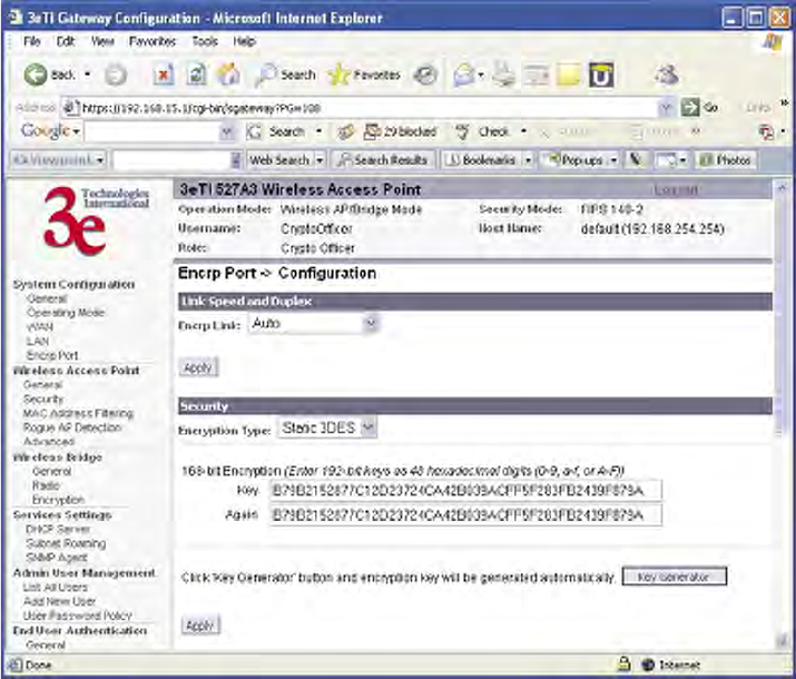
Static 3DES Key
To use 3DES, enter a 192-bit key as 48 hexadecimal digit (0-9, a-f, or
A-F).
The Key Generator button automatically generates a randomized key
of the appropriate length. This key is initially shown in plain text so the
user has the opportunity to copy the key. Once the key is applied, the key
is no longer displayed in plain text.
3e–527A3 Wireless Access Point – 8 Port Chapter 3: Access Point Conguration
26 29000152-001 B
3e–527A3 Wireless Access Point – 8 Port Chapter 3: Access Point Conguration
29000152-001 B 27
Wireless Access Point Conguration
General
Wireless Setup allows your computer’s PC Card to communicate with
the access point. Once you have completed wireless access point congu-
ration, you can complete the rest of the conguration wirelessly unless
you will be employing the FIPS 140-2 secure mode, assuming that you
have installed and congured a wireless PC card on your computer. (If
you have not done so, you will have to do that to establish communica-
tions. Follow the manufacturer's instructions to set up the PC Card on
each wireless device that will be part of the WLAN.)
NOTE: The 3e–527A3 is always in FIPS 140-2 secure mode, there-
fore your conguration will have to be accomplished through the
LAN port due to the secure nature of the access point. There is no
direct access from wireless clients.
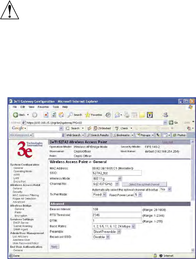
The Wireless Access Point — General screen lists the MAC Address
of the AP card. This is not the MAC Address that will be used for the BS-
SID for bridging setup, however. That is found on the Wireless Bridge
— Radio screen.
If you will be using an SSID for a wireless LAN, enter it here and in
the setup of each wireless client. This nomenclature has to be set on the
access point and each wireless device in order for them to communicate.

3e–527A3 Wireless Access Point – 8 Port Chapter 3: Access Point Conguration
26 29000152-001 B
3e–527A3 Wireless Access Point – 8 Port Chapter 3: Access Point Conguration
29000152-001 B 27
Select the wireless mode from the drop-down list. You can choose
from the following options:
• 802.11b
• 802.11g
• 802.11b/g Mixed
You can assign a channel number to the AP (if necessary) and modify
the Tx Pwr Mode.
The Channel Number is a means of assigning frequencies to a series
of access points, when many are used in the same WLAN, to minimize
noise. There are 11 channel numbers that may be assigned. If you assign
channel number 1 to the rst in a series, then channel 6, then channel 11,
and then continue with 1, 6, 11, you will have the optimum frequency
spread to decrease “noise.”
If you click on the button Select the optimal channel, a popup screen
will display the choices. It will select the optimal channel for you. You can
also set it up to automatically select the optimal channel at boot up.
CHANNEL NO. OPTIONS
Wireless Mode Channel No.
802.11b
802.11g
802.11b/g Mixed
1 (2.412 GHz)
2 (2.417 GHz)
3 (2.422 GHz)
4 (2.427 GHz)
5 (2.432 GHz)
6 (2.437 GHz)
7 (2.442 GHz)
8 (2.447 GHz)
9 (2.452 GHz)
10 (2.457 GHz)
11 (2.462 GHz)

3e–527A3 Wireless Access Point – 8 Port Chapter 3: Access Point Conguration
28 29000152-001 B
3e–527A3 Wireless Access Point – 8 Port Chapter 3: Access Point Conguration
29000152-001 B 29
Tx Pwr Mode and Fixed Pwr Level: The Tx Power Mode defaults to
Auto, giving the largest range of radio transmission available under nor-
mal conditions. As an option, the AP's broadcast range can be limited by
setting the Tx Power Mode to Fixed and choosing from 1-8 for Fixed Pwr
Level (1 being the shortest distance.) Finally, if you want to prevent any
radio frequency transmission, set Tx Pwr Mode to Off.
There are a number of advanced options included on this page as
described in the following chart:
ADVANCED OPTIONS
Beacon interval 20-1000 The time interval in milliseconds in which the
802.11 beacon is transmitted by the AP.
RTS Threshold 1-2346 The number of bytes used for the RTS/CTS
handshake boundary. When a packet size is
greater than the RTS threshold, the RTS/CTS
handshaking is performed.
DTIM 1-255 The number of beacon intervals that broadcast
and multicast trafc is buffered for a client in
power save mode.
Basic Rates Basic Rates for 802.11b
1 and 2 Mbps
1, 2, 5.5 and 11
Mbps
The basic rates used and reported by the
AP. The highest rate specied is the rate that
the AP uses when transmitting broadcast/
multicast and management frames.
Basis Rates for 802.11g
1, 2, 5.5, 11, 6,
12, 24 Mbps
1, 2, 5.5, 11
Mbps
The basic rates used and reported by the
AP. The highest rate specied is the rate that
the AP uses when transmitting broadcast/
multicast and management frames.
Basic Rates for 802.11b/g Mixed
1, 2 Mbps
1, 2, 5.5, 11
Mbps
The basic rates used and reported by the
AP. The highest rate specied is the rate that
the AP uses when transmitting broadcast/
multicast and management frames.
Preamble Short/Long
Preamble
Species whether frames are transmitted with
the Short or Long Preamble
Broadcast SSID Enabled/
Disabled
When disabled, the AP hides the SSID in
outgoing beacon frames and stations cannot
obtain the SSID through passive scanning.
Also, when it is disabled, the AP doesn’t
send probe responses to probe requests with
unspecied SSIDs.
3e–527A3 Wireless Access Point – 8 Port Chapter 3: Access Point Conguration
28 29000152-001 B
3e–527A3 Wireless Access Point – 8 Port Chapter 3: Access Point Conguration
29000152-001 B 29
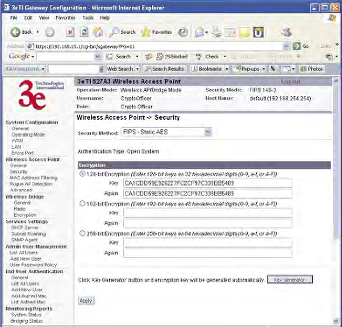
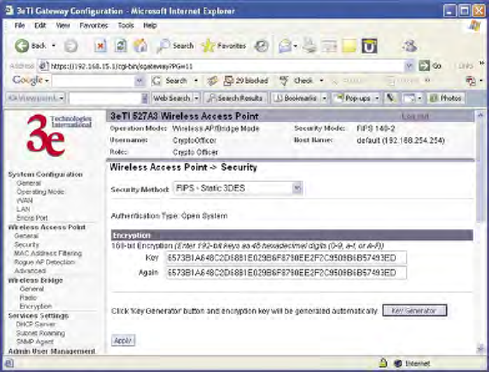
Security
The Wireless Access Point — Security screen displays a default fac-
tory setting of AES encryption, but the encryption key is not set and it
will not communicate to any clients unless the encryption is set by the
CryptoOfcer.
NOTE: One of the encryption options must be selected and applied in
order for the AP to communicate with other APs.
Static AES Key
The Advanced Encryption Standard (AES) was selected by National
Institute of Standards and Technology (NIST) in October 2000 as an up-
grade from the previous DES standard. AES uses a 128-bit block cipher
algorithm and encryption technique for protecting computerized infor-
mation. With the ability to use even larger 192-bit and 256-bit keys, if
desired, it offers higher security against brute-force attack than the old
56-bit DES keys.
The Key Generator button automatically generates a randomized key
of the appropriate length. This key is initially shown in plain text so the
user has the opportunity to copy the key. Once the key is applied, the key
is no longer displayed in plain text.
3e–527A3 Wireless Access Point – 8 Port Chapter 3: Access Point Conguration
30 29000152-001 B
3e–527A3 Wireless Access Point – 8 Port Chapter 3: Access Point Conguration
29000152-001 B 31
Static 3DES Key
To use 3DES, enter a 192-bit key as 48 hexadecimal digit (0-9, a-f, or
A-F).
The Key Generator button automatically generates a randomized key
of the appropriate length. This key is initially shown in plain text so the
user has the opportunity to copy the key. Once the key is applied, the key
is no longer displayed in plain text.
3e–527A3 Wireless Access Point – 8 Port Chapter 3: Access Point Conguration
30 29000152-001 B
3e–527A3 Wireless Access Point – 8 Port Chapter 3: Access Point Conguration
29000152-001 B 31
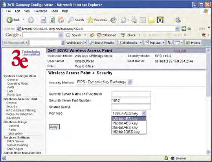
Dynamic Key Exchange
Dynamic key management requires the installation of the 3e-030
Security Server software which resides on a self-contained workstation
connected to the 3e–527A3 over the WAN port. The Security Server soft-
ware conguration includes: obtaining a root certicate from a Certicate
Authority (CA) like Microsoft; obtaining user certicates based on the CA
which will be used by the clients; and conguring the 3e Technologies
International's Security Server software with the appropriate root certi-
cate. The Security Server software application is discussed in a separate
manual.
If you have installed the Security Server software, Dynamic Key
Management is the preferred security setup. Congure the IP address
and password of the security server and set the key type. Key type will be
either 3DES (192-bit), or AES (128-bit, 192-bit or 256-bit). Thereafter, the
Security Server handles authentication dynamically.
Once you have selected the options you will use, click Apply.
3e–527A3 Wireless Access Point – 8 Port Chapter 3: Access Point Conguration
32 29000152-001 B
3e–527A3 Wireless Access Point – 8 Port Chapter 3: Access Point Conguration
29000152-001 B 33
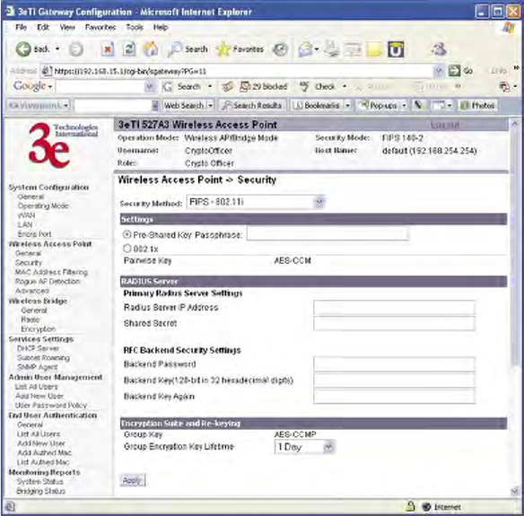
FIPS 802.11i
If you wish to use FIPS 802.11i on the 3e–527A3, enable either Pre-
shared Key Settings or 802.1x Settings.
If you are a SOHO user, selecting pre-shared key means that you
don’t have the expense of installing a Radius Server. Simply input up to
63 character / numeric / hexadecimals in the Passphrase eld.
Enable pre-authentication to allow a client to authenticate in advance
with the AP before the client is associated with it. Allowing the AP to
pre-authenticate a client decreases the transition time when a client roams
between APs.
As an alternative, for business applications who have installed Ra-
dius Servers, select 802.1x and input the Primary Radius Server and RFC
Backend security settings. Use of Radius Server for key management and
authentication requires that you have installed a separate certication sys-
tem and each client must have been issued an authentication certicate.
Re-keying time is the frequency in which new encryption keys are
generated and distributed to the client. The more frequent re-keying, the
better the security. For highest security, select the lowest re-keying inter-
val.
Once you have selected the options you will use, click Apply.
If you will be using MAC Address ltering, navigate next to the MAC
Address Filtering screen.
3e–527A3 Wireless Access Point – 8 Port Chapter 3: Access Point Conguration
32 29000152-001 B
3e–527A3 Wireless Access Point – 8 Port Chapter 3: Access Point Conguration
29000152-001 B 33
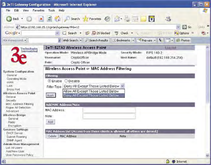
MAC Address Filtering
The Wireless Access Point — MAC Address Filtering screen is used
to set up MAC address ltering for the 3e–527A3 device. The factory de-
fault for MAC Address ltering is Disabled. If you enable MAC Address
ltering, you should also set the toggle for Filter Type.
This works as follows:
• If Filtering is enabled and Filter Type is Deny All Except Those
Listed Below, only those devices equipped with the authorized
MAC addresses will be able to communicate with the access
point. In this case, input the MAC addresses of all the PC cards
that will be authorized to access this access point. The MAC ad-
dress is engraved or written on the PC (PCMCIA) Card.
• If Filtering is enabled and Filter Type is Allow All Except Those
Listed Below, those devices with a MAC address which has been
entered in the MAC Address listing will NOT be able to commu-
nicate with the access point. In this case, navigate to the report:
Wireless Clients and copy the MAC address of any Wireless Cli-
ent that you want to exclude from communication with the access
point and input those MAC Addresses to the MAC Address list.
3e–527A3 Wireless Access Point – 8 Port Chapter 3: Access Point Conguration
34 29000152-001 B
3e–527A3 Wireless Access Point – 8 Port Chapter 3: Access Point Conguration
29000152-001 B 35
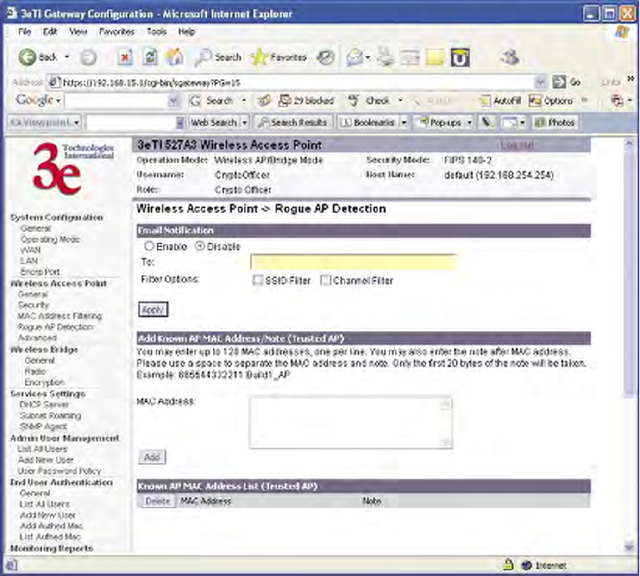
Rogue AP Detection
The Wireless Access Point — Rogue AP Detection screen allows the
network administrator to set up rogue AP detection. Enable rogue AP
detection and enter the MAC Address of each AP in the network that you
want the AP being congured to accept as a trusted AP. (You may add
up to 128 MAC addresses.) Enter an email address for notication of any
rogue or non-trusted APs. (The MAC Address for the 3e–527A3 is located
on the System Conguration — General screen. You can also select the
following lter options.
• SSID FIlter: Check the SSID option to only send rogue APs that
match the AP's SSID or wireless bridge's SSID.
• Channel Filter: Check the channel lter option to only send rogue
APs that match the AP's channel or the wireless bridge's channel.
• If both options are checked, only APs that match both the SSID
and channel are sent.
The Adjacent AP list, under Monitoring/Reports on the navigation
menu, will detail any marauding APs.
3e–527A3 Wireless Access Point – 8 Port Chapter 3: Access Point Conguration
34 29000152-001 B
3e–527A3 Wireless Access Point – 8 Port Chapter 3: Access Point Conguration
29000152-001 B 35
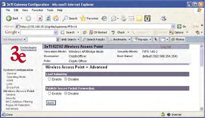
Advanced
The Wireless Access Point — Advanced screen allows you to enable
or disable load balancing and publicly secure packet forwarding.
Load balancing is disabled by default. The load balancing feature bal-
ances the wireless clients between APs. If two APs with similar settings
are in a conference room, depending on the location of the APs, all wire-
less clients could potentially associate with the same AP, leaving the other
AP unused. Load balancing attempts to evenly distribute the wireless
clients on both APs.
When publicly secure packet forwarding is enabled, wireless clients
can not talk to other wireless clients directly at Layer 2. However, they
both can have access to others that are not associating to the same AP.
Once you have made any changes, click Apply to save.
Wireless Bridge
The Wireless Bridge screens are described in Chapter 5.
3e–527A3 Wireless Access Point – 8 Port Chapter 3: Access Point Conguration
36 29000152-001 B
3e–527A3 Wireless Access Point – 8 Port Chapter 3: Access Point Conguration
29000152-001 B 37
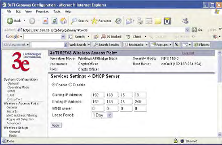
Services Settings
DHCP Server
The Service Settings — DHCP Server screen is used for congur-
ing the DHCP server function accessible from the Local LAN port. The
default factory setting for the DHCP server function is enabled. You can
disable the DHCP server function, if you wish, but it is not recommended.
You can also set the range of addresses to be assigned. The Lease period
(after which the dynamic address can be reassigned) can also be varied.
The DHCP server function, accessible only from the LAN port, is used
for initial conguration of the management functions.
3e–527A3 Wireless Access Point – 8 Port Chapter 3: Access Point Conguration
36 29000152-001 B
3e–527A3 Wireless Access Point – 8 Port Chapter 3: Access Point Conguration
29000152-001 B 37
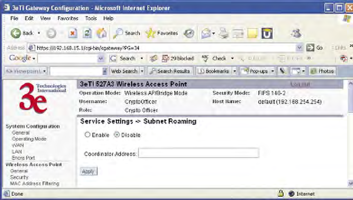
Subnet Roaming
The 3e-527A3 supports subnet roaming with 3eTI's subnet roaming coor-
dinator server installed. Subnet roaming occurs when a user roams to an
access point that is connected to a different subnet than its home subnet.
If subnet roaming is supported by the wireless infrastructure, the client
is able to continue its network connectivity without having to change its
IP address. Therefore, to the mobile device, roaming is transparent and it
will continue to function as if it is in its home subnet.
The coordinator is a separate server that keeps track of the client's
home network. The software is available from 3eTI upon request.
3e–527A3 Wireless Access Point – 8 Port Chapter 3: Access Point Conguration
38 29000152-001 B
3e–527A3 Wireless Access Point – 8 Port Chapter 3: Access Point Conguration
29000152-001 B 39
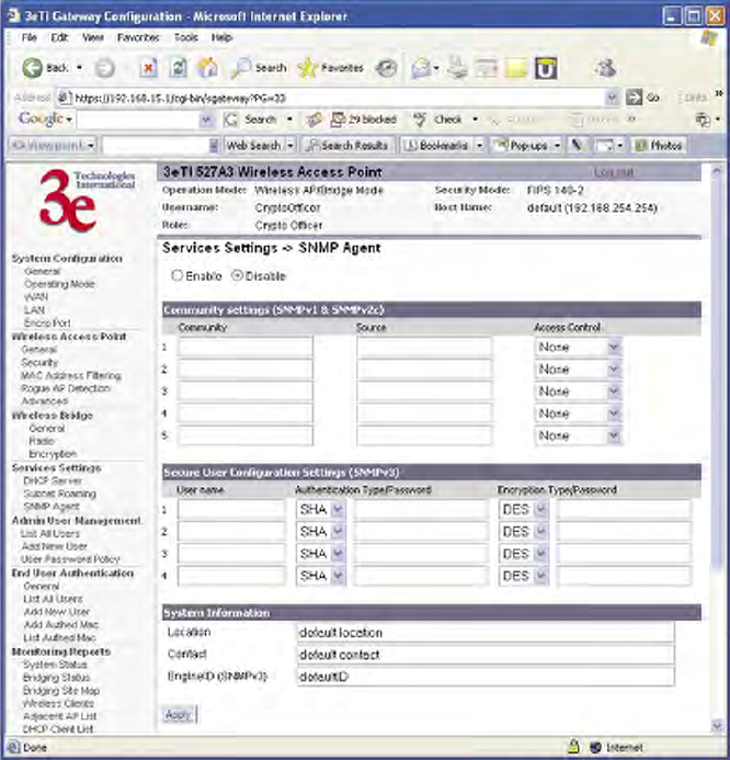
SNMP Agent
The Service Settings — SNMP Agent screen allows you to set up
an SNMP Agent. The agent is a software module that collects and stores
management information for use in a network management system. The
3e–527A3's integrated SNMP agent software module translates the de-
vice’s management information into a common form for interpretation by
the SNMP Manager, which usually resides on a network administrator’s
computer.
The SNMP Manager function interacts with the SNMP Agent to
execute applications to control and manage object variables (interface
features and devices) in the gateway. Common forms of managed infor-
mation include number of packets received on an interface, port status,
dropped packets, and so forth. SNMP is a simple request and response
protocol, allowing the manager to interact with the agent to either:
• Get - Allows the manager to Read information about an object
variable
• Set - Allows the manager to Write values for object variables with-
in an agent’s control, or
• Trap - Allows the manager to Capture information and send an
alert about some pre-selected event to a specic destination.
3e–527A3 Wireless Access Point – 8 Port Chapter 3: Access Point Conguration
38 29000152-001 B
3e–527A3 Wireless Access Point – 8 Port Chapter 3: Access Point Conguration
29000152-001 B 39
The SNMP conguration consists of several elds, which are ex-
plained below:
• Community –The Community eld for Get (Read Only), Set
(Read & Write), and Trap is simply the SNMP terminology for
“password” for those functions.
• Source –The IP address or name where the information is ob-
tained.
• Access Control –Denes the level of management interaction per-
mitted.
If using SNMPv3, enter a username (minimum of eight characters),
authentication type with key and data encryption type with a key. In FIPS
mode, only SHA and AES are supported. This conguration information
will also need to be entered in your MIB manager setup.
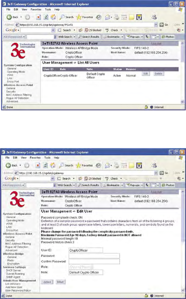
3e–527A3 Wireless Access Point – 8 Port Chapter 3: Access Point Conguration
40 29000152-001 B
3e–527A3 Wireless Access Point – 8 Port Chapter 3: Access Point Conguration
29000152-001 B 41
Admin User Management
List All Users
The Admin User Management — List All Users screen lists the
Crypto Ofcer and administrator accounts congured for the unit. You
can edit or delete users from this screen.
If you click on Edit, the Admin User Management — Edit User
screen appears. On this screen you can edit the user ID, password, role,
and note elds.
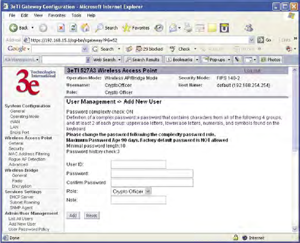
3e–527A3 Wireless Access Point – 8 Port Chapter 3: Access Point Conguration
40 29000152-001 B
3e–527A3 Wireless Access Point – 8 Port Chapter 3: Access Point Conguration
29000152-001 B 41
Add New User
The Admin User Management — Add New User screen allows you
to add new Administrators and CryptoOfcers, assigning and conrming
the password.
Administrators can view the system but this role has limited access to
change settings. CryptoOfcers can view and change any of the settings
on the system.
The Password complexity check and the Minimal Password length
are established on the Admin User Management — User Password
Policy screen.
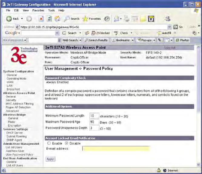
3e–527A3 Wireless Access Point – 8 Port Chapter 3: Access Point Conguration
42 29000152-001 B
3e–527A3 Wireless Access Point – 8 Port Chapter 3: Access Point Conguration
29000152-001 B 43
User Password Policy
The Admin User Management — User Password Policy screen is
always enabled. The denition of a complex password is a password that
contains characters from all of the following 4 groups and at least 2 of
each group: uppercase letters, lowercase letters, numerals, and symbols
found on the keyboard. The minimum password length is 10 characters
and the maximum length is 30.
The maximum password age is congurable from 30 to 90 days. The
default is 90 days. If you do not change your password after the maxi-
mum password age expires, you will not have access to the unit. Howev-
er, you have until 150 days of the password age to change the password.
You will be prompted to change your password from 90-150 days. After
150 days, the account will be locked and the CryptoOfcer will have to
unlock it for you. The only exception to this rule is if you are the last ac-
tive CryptoOfcer user.
You can also set the password uniqueness depth. This means a for-
mer password can not be reused. The depth is congurable from 3 to 10.
For example, if the password uniqueness depth is set to 3, then the last 3
passwords can not be reused when changing your password.
The default for the account lockout email notication is set to disable.
If enabled, the system will send an email to the email address listed to
inform that person that a user has been locked out of the system. To con-
gure the email notication go to the System Administration — Email
Notication Conf screen.
Click Apply to save your selection.
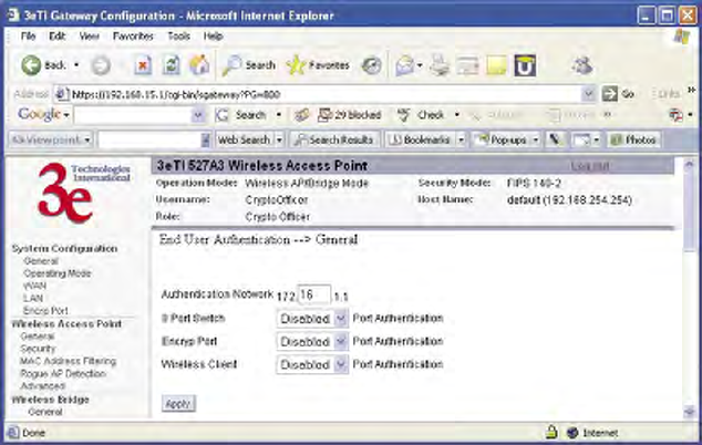
3e–527A3 Wireless Access Point – 8 Port Chapter 3: Access Point Conguration
42 29000152-001 B
3e–527A3 Wireless Access Point – 8 Port Chapter 3: Access Point Conguration
29000152-001 B 43
End User Authentication
In the 3e-527A3, all end users (wireless and wired), may require an
account in order to have access to the Internet. Each end user is required
to input their user name and password to authenticate with the system.
Once you have authenticated, you will not need to re- authenticate for 24
hours unless your CryptoOfcer requires you to. To authenticate, open
a browser and enter any resolvable URL. The system will redirect you to
the authentication page. Once here, we assume that the client to be au-
thenticated has access to DHCP and DNS servers.
NOTE: During authentication, the 3e-527C may leave a false cookie of
the URL on the client PC. You should delete this cookie. Otherwise, if the
system forces you to re-authenticate, you may be prompted to delete the
cookie.
General
End user authentication needs a private local network to operate.
This private network should never be the same as the LAN or WAN.
By default, the private network IP is 172.16.0.0. It is congurable from
172.16.0.0 to 172.31.0.0.
You can partially enable/disable end user authentication. If the 8-port
switch feature is enabled, then all wired clients connecting to the 8-port
switch need to authenticate. If the encryp port feature is enabled, then
any clients attached to the encryp port need to authenticate. If the wire-
less client feature is enabled, then all wireless clients need to authenticate.
There is one exception however. If the end user network adapter
MAC address is manually added in the database, the PC with that adapt-
er doesn't need to authenticate. This is usually used for a TRUSTED user
or system server.
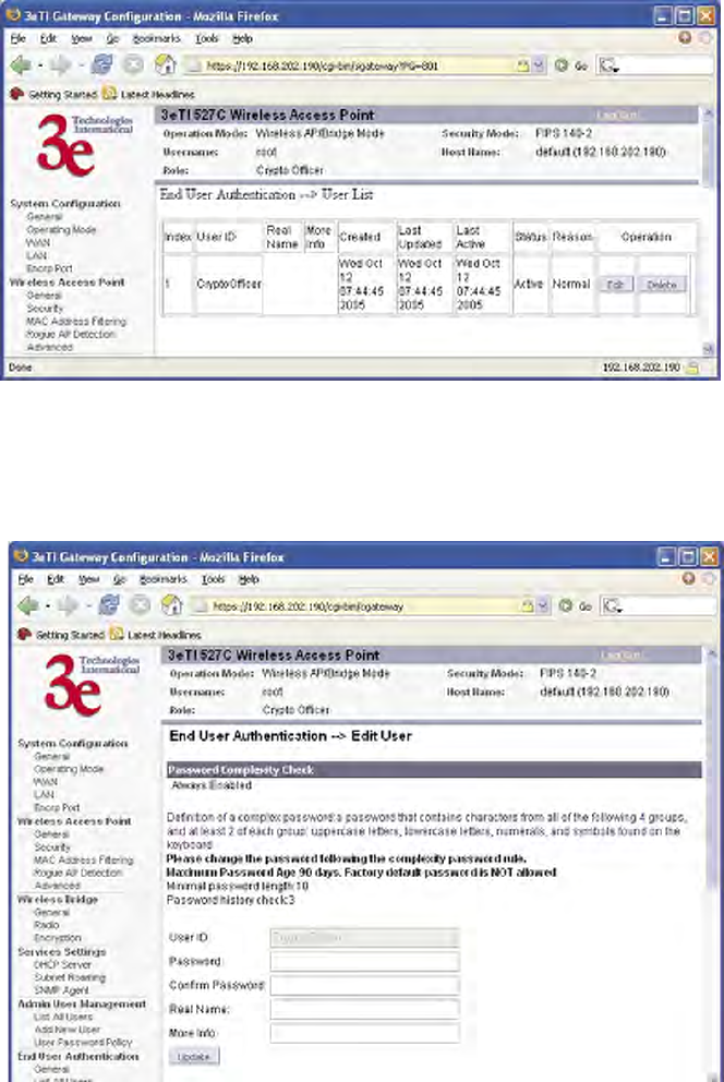
3e–527A3 Wireless Access Point – 8 Port Chapter 3: Access Point Conguration
44 29000152-001 B
3e–527A3 Wireless Access Point – 8 Port Chapter 3: Access Point Conguration
29000152-001 B 45
User List
The End User Authentication — User List screen lists all end user
information. The CryptoOfcer can edit, delete, and unlock users from
this screen.
If you click on Edit, the End User Authentication — Edit User screen
appears. On this screen you can edit the user ID, password, role, and
note elds.
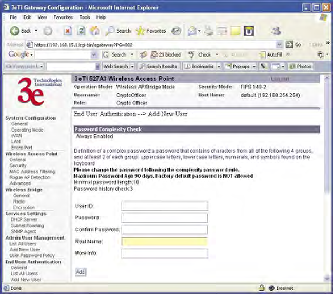
3e–527A3 Wireless Access Point – 8 Port Chapter 3: Access Point Conguration
44 29000152-001 B
3e–527A3 Wireless Access Point – 8 Port Chapter 3: Access Point Conguration
29000152-001 B 45
Add New User
The End User Authentication — Add New User screen allows you to
add new end users, assigning and conrming the password.
Administrators can view the system but this role has limited access to
change settings. CryptoOfcers can view and change any of the settings
on the system.
The password policy is the same as the Admin User Management
— User Password Policy screen.
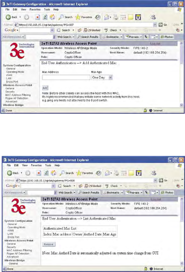
3e–527A3 Wireless Access Point – 8 Port Chapter 3: Access Point Conguration
46 29000152-001 B
3e–527A3 Wireless Access Point – 8 Port Chapter 3: Access Point Conguration
29000152-001 B 47
Add Authenticated MAC
Usually the authenticated MAC is valid for 24 hours. You will be re-
quested to re-authenticate after it expires. In case there is a client without
user interaction (for example, a server), you may not want to authenticate
that client every 24 hours. You can manually set the authenticated MAC
in the authenticated list and mark the entry Permanent. Another use case
would be to mark it as Temporarily trusted PC.
NOTE: If you manually add an authenticated MAC, we strongly
recommend that you initiate some network activity to hosts that are not
attached to the same 8-port switch. We also recommend that you not at-
tach servers and other un-trusted PCs on the same 8-port switch on the
3e-527A3.
List Authenticated MAC
This screen provides a list of all of the authenticated MAC addresses.
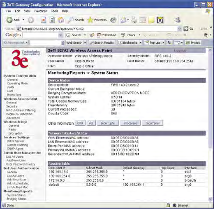
3e–527A3 Wireless Access Point – 8 Port Chapter 3: Access Point Conguration
46 29000152-001 B
3e–527A3 Wireless Access Point – 8 Port Chapter 3: Access Point Conguration
29000152-001 B 47
Monitoring/Reports
This section gives you a variety of lists and status reports. Most of
these are self-explanatory.
System Status
The Monitoring/Report — System Status screen displays the status
of the 3e–527A3 device, the network interface, and the routing table.
There are some pop-up informational menus that give detailed infor-
mation about CPU, PCI, Interrupts, Process, and Interfaces.
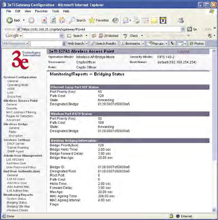
3e–527A3 Wireless Access Point – 8 Port Chapter 3: Access Point Conguration
48 29000152-001 B
3e–527A3 Wireless Access Point – 8 Port Chapter 3: Access Point Conguration
29000152-001 B 49
Bridging Status
The Monitoring/Report — Bridging Status screen displays the Ether-
net Port STP status, Encryp Port STP status, Wireless Port STP status, and
Wireless Bridging information.
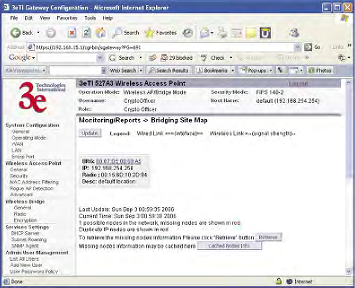
3e–527A3 Wireless Access Point – 8 Port Chapter 3: Access Point Conguration
48 29000152-001 B
3e–527A3 Wireless Access Point – 8 Port Chapter 3: Access Point Conguration
29000152-001 B 49
Bridge Site Map
The Bridge Site Map shows the spanning tree network topology of
both wired and wireless nodes connected to the network. The root STP
node is always on top and the nodes of the hierarchy are displayed below
it. Wired links are double dotted lines and wireless links are single dot-
ted lines (the channel number of this wireless link is also shown). This
map does not update dynamically. You must press the Update button to
refresh the map.
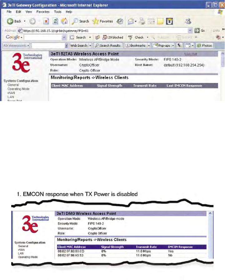
3e–527A3 Wireless Access Point – 8 Port Chapter 3: Access Point Conguration
50 29000152-001 B
3e–527A3 Wireless Access Point – 8 Port Chapter 3: Access Point Conguration
29000152-001 B 51
Wireless Clients
The Monitoring/Report — Wireless Clients screen displays the MAC
Address of all wireless clients and their signal strength and transmit rate.
The screen shown here emulates the FIPS 140-2 setup and contains a col-
umn for EMCON response. The EMCON feature only works with 3e-010F
Crypto Client in FIPs mode.
If Transmit power is disabled, either by setting TX Pwr Mode to Off
on the management screen or by using the RF Manager (Chapter 7), the
Wireless Clients page will show the results from each associated client
in the EMCON Response column. If the client responds to the "disable"
command, a Yes is displayed. If the column contains a No, this can mean
either:
• the client didn't receive the command, or
• the client is no longer in the areas, or
• the client software doesn't support the RF management feature.
This status information remains active for 5 minutes after the clients
are disabled.
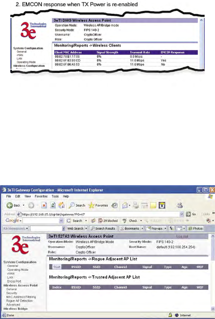
3e–527A3 Wireless Access Point – 8 Port Chapter 3: Access Point Conguration
50 29000152-001 B
3e–527A3 Wireless Access Point – 8 Port Chapter 3: Access Point Conguration
29000152-001 B 51
Once the transmit power is re-enabled and clients re-associate to the
AP, EMCON information is maintained for them. If a new client that
wasn't associated previously associates with the AP after the EMCON
mode, its EMCON status appears as "-", which indicates the status record
is not applicable.
Adjacent AP List
The Monitoring/Report — Adjacent AP List screen shows all the APs
on the network. If you select the check box next to any AP shown, the AP
will thereafter be accepted by the 3e–527A3 as a trusted AP.
These APs are detected by the AP's wireless card (2.4 GHz band) and
the wireless bridge's wireless card (5.8GHz band). The list of APs are only
within the band that can be seen from a particular channel. For example,
if the AP is on channel 1, it will display APs on channels 1-3. Adjacent
APs are displayed for ve minutes.
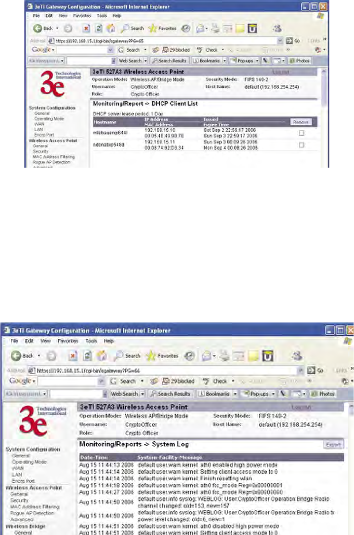
3e–527A3 Wireless Access Point – 8 Port Chapter 3: Access Point Conguration
52 29000152-001 B
3e–527A3 Wireless Access Point – 8 Port Chapter 3: Access Point Conguration
29000152-001 B 53
DHCP Client List
The Monitoring/Report — DHCP Client List screen displays all
clients currently connected to the 3e–527A3 via DHCP server, including
their hostnames, IP addresses, and MAC Addresses.
The DHCP Client list constantly collects entries. To remove entries
from the list, check mark the Revoke Entry selection and click Remove to
conrm the action.
System Log
The Monitoring/Report — System Log screen displays system facil-
ity messages with date and time stamp. These are messages documenting
functions performed internal to the system, based on the system’s func-
tionality. Generally, the Administrator would only use this information if
trained as or working with a eld engineer or as information provided to
technical support.
The System log continues to accumulate listings and rotates when it
reaches the dened maximum size. You can never delete this log but you
can export the log to a le on a PC.
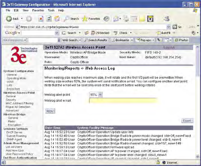
3e–527A3 Wireless Access Point – 8 Port Chapter 3: Access Point Conguration
52 29000152-001 B
3e–527A3 Wireless Access Point – 8 Port Chapter 3: Access Point Conguration
29000152-001 B 53
Web Access Log
The Web Access Log displays system facility messages for any con-
guration changes via the web GUI. Along with the old value and new
value, the when/who/what changes are also recorded. For security
reasons, some sensitive data may not be recorded (for example, the en-
cryption key) or may not be completely recorded (for example, the au-
thenticated MAC). For example, this log records when you set encryption
mode, change operating mode, etc., using the web browser. It establishes
a running record regarding what actions were performed and by whom.
The Web access log will continue to accumulate listings and rotate by
half when it reaches the dened maximum size (10 Kbytes). If congured,
an email notication will be sent when the weblog grows to 50% of the
maximum size for the rst time. You can also set another alert point of 60-
90% of the maximum size and an email notication will be sent when this
alert point is reached. You should export the web log to a PC before the
maximum size is reached to the log does not get overwritten. An email
will be sent only once. The exception is if the unit is rebooted, then it will
send an email on each reboot.
NOTE: You need to set up email notication using the System Admin-
istration — Email Notication Conf screen before any emails can be sent
from the unit.
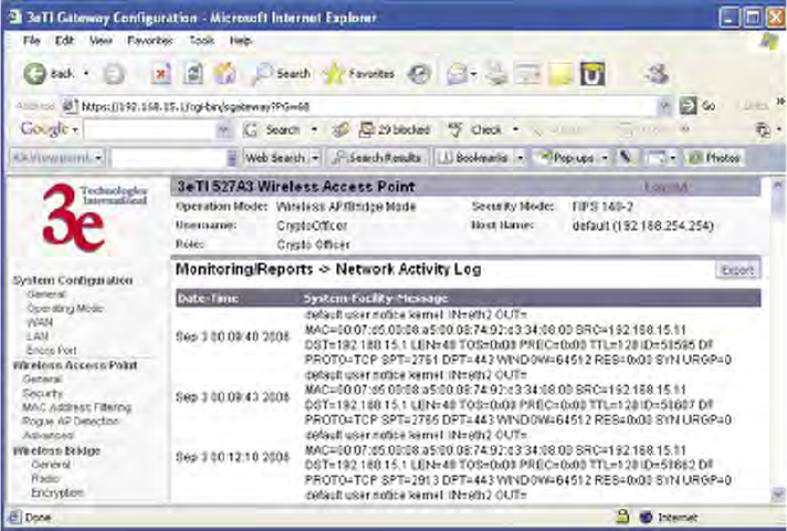
3e–527A3 Wireless Access Point – 8 Port Chapter 3: Access Point Conguration
54 29000152-001 B
3e–527A3 Wireless Access Point – 8 Port Chapter 3: Access Point Conguration
29000152-001 B 55
Network Activity
The Network Activity Log keeps a detailed log of all activities on the
network which can be useful to the network administration staff.
The Network Activities log will continue to accumulate listings and
rotates when the log reaches the dened maximum size. You can never
delete this log but you can export the log to a le on a PC.
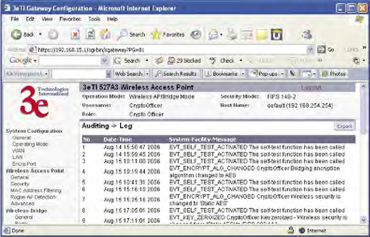
3e–527A3 Wireless Access Point – 8 Port Chapter 3: Access Point Conguration
54 29000152-001 B
3e–527A3 Wireless Access Point – 8 Port Chapter 3: Access Point Conguration
29000152-001 B 55
Auditing
The 3e-527A3 collects audit data and provides an interface for au-
thorized administrators to review generated audit records. It generates
records for two separate classes of events: authentication/access to the
system, and actions taken directly on the system. All audit records in-
clude the date/time of the event, the identity associated with the event
(such as the service, computer or user), the success/failure of the event
and a denition of the event (by code or explanation).
Every start and stop of the audit service is noted in the audit record.
For audit events resulting from actions of identied users, the 3e-527A3
shall be able to associate each auditable event with the identity of the user
that caused the event. The 3e-527A3 shall be able to include or exclude
auditable events from the set of audited events based on object identity,
user identity, subject identity, host identity, and event type.
The TOE (Target of Evaluation) provides tools which can be used to
review the audit records. These tools allow the user to query for records
based on the identity associated with the record, such as the user or com-
puter which is associated with the event.
The Auditing screens contain auditing functions for the system. The
screens and functions are detailed in the following subsections.
Log
The Auditing—Log screen provides a listing of all the audit records.
This log will rotate after it reaches the dened maximum size. You can not
delete this log but you can export the le to a PC.
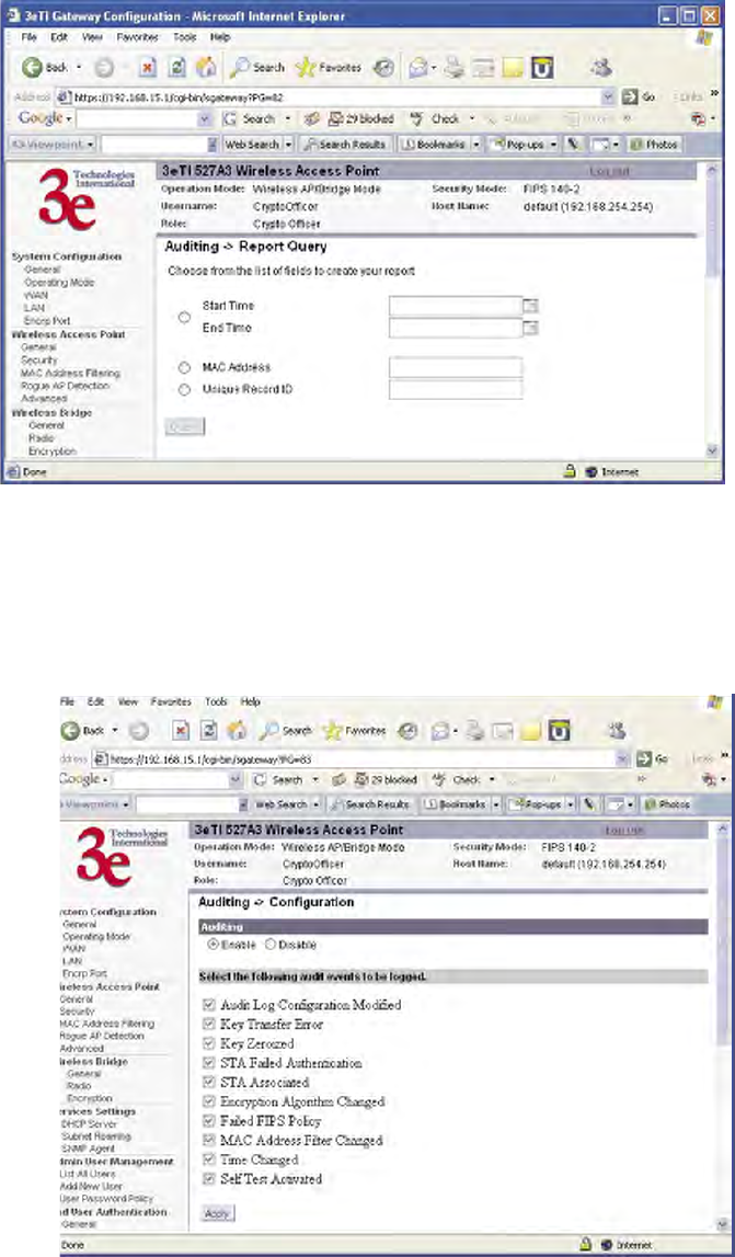
3e–527A3 Wireless Access Point – 8 Port Chapter 3: Access Point Conguration
56 29000152-001 B
3e–527A3 Wireless Access Point – 8 Port Chapter 3: Access Point Conguration
29000152-001 B 57
Report Query
The Auditing—Report Query screen allows you to query on report
based on start time, end time, MAC address, or unique record IDs.
Conguration
The Auditing—Conguration screen is used to congure the auditing
settings. You can enable and disable the auditing function on this screen.
You can select which audit event types you wish to log. The following
gure shows the screen and the table lists event types and descriptions.

3e–527A3 Wireless Access Point – 8 Port Chapter 3: Access Point Conguration
56 29000152-001 B
3e–527A3 Wireless Access Point – 8 Port Chapter 3: Access Point Conguration
29000152-001 B 57
Event Type Description
Audit Log Conguration Modied Any modication to the audit log
conguration (enable/disable,
recorded event types, etc) will trig-
ger the creation of an audit record.
Key Transfer Error Any error detected during the
dynamic key exchange, either to
the station or the authentication
server.
Key Zeroized The keys are zeroized including:
1. Transitioning from static key to
DKE (and vice versa)
2. Transitioning to bypass mode
Individual log messages appear
from the application and driver
since keys are held in both loca-
tions.
STA Failed Authentication A station's authentication request
is dropped because it doesn't
match the MAC address lter.
STA Associated A station successfully associates to
the AP.
Encryption Algorithm Changed The encryption algorithm is
changed, including bypass mode.
Failed FIPS Policy All HMAC/AES decrypt errors
that can be detected.
MAC Filter Changed The MAC address lter is changed
including adding/deleting,
enable/disable, and changing lter
type.
Time Changed Whenever the time is changed via
the GUI or at bootup if the time is
within two minutes of 11/30/1999,
0hr, 0min.
Self Test Activated The self-test function is run.
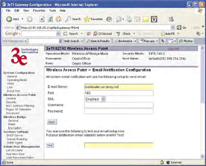
3e–527A3 Wireless Access Point – 8 Port Chapter 3: Access Point Conguration
58 29000152-001 B
3e–527A3 Wireless Access Point – 8 Port Chapter 3: Access Point Conguration
29000152-001 B 59
System Administration
The System administration screens contain administrative functions.
The screens and functions are detailed in the following section.
Email Notication Conguration
All system notication emails need to be set up using the System
Administration — Email Notication Conguration screen. Your email
server must support SMTP protocol. If you email server does not require
authentication to send email then leave the username/password elds
blank. If your email server does not support SSL (Secure Socket Layer)
then disable SSL on the 3e-527A3. You may also test your email setup us-
ing the test feature on this screen.
NOTE: Check your connection to the mail server. Emails sent from the
3e-527A3 may be queued for a short period if the connection fails tempo-
rarily, but it will give up if the connection continues to fail.

3e–527A3 Wireless Access Point – 8 Port Chapter 3: Access Point Conguration
58 29000152-001 B
3e–527A3 Wireless Access Point – 8 Port Chapter 3: Access Point Conguration
29000152-001 B 59
Conguration-Button
The System Administration—Conguration Button screen is used in
conjunction with the physical Conguration/RESET button which is ac-
cessible from the outside of the 3e–527A3 unit. The Conguration/RESET
button is located directly under the number “1” on the front panel. Use a
plastic wire wrap or something similar and slide it in-between the gray
panel and the Ethernet jack (RJ-45 jack) at an angle so that the tip touches
the button hidden under the number “1”. You will know you have located
the Conguration/RESET button when you push and “feel” a click.
NOTE: A metal paper clip is not recommended as it may damage the
reset switch and after time the switch will not be water resistant anymore.
In order to minimize the administration effort of the AP, the external
RESET button has been converted into a conguration button to perform
certain functions. This conguration button is programmed to perform
the following operations.
• Send the conguration le to other APs that are connected to
ports 1-6 and the PoE/Uplink port (requires a password)
Note that the conguration le transfer only goes to devices that
are connected to the Ethernet ports. The conguration does not
get transferred to devices connected wirelessly or through the
Encrp port.
• Normal Reset (hold button for ve seconds then release, see de-
tails below)
• Factory Default (hold button for 10 seconds then release, see de-
tails below)
The System Administration—Conguration Button screen is where
you can enable the conguration button. The conguration button is
disabled by default and doesn't have a password. Once the button is en-
abled, a password must be entered (not needed for reset or factory default
functions). In order to perform a conguration transfer, you must enter
the password (8 digits between 1-9).
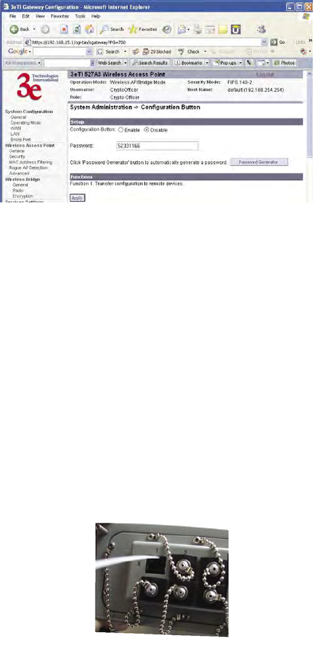
3e–527A3 Wireless Access Point – 8 Port Chapter 3: Access Point Conguration
60 29000152-001 B
3e–527A3 Wireless Access Point – 8 Port Chapter 3: Access Point Conguration
29000152-001 B 61
To use the Conguration/RESET button push the button for two
seconds. After two seconds the WLAN2 and WLANSS LEDs are turned
off. These two LEDs can then be used as input indicators.
The procedure to enter the password is:
Example: 11111111
Push the Conguration/RESET button once (input is acknowl-
edged by the signal strength LED) and wait for one second. The WLAN2
LED blinks to acknowledge the rst digit was accepted. Repeat eight
times.
To reset the unit:
1. Push in and hold the Conguration/RESET button for ve sec-
onds (input is acknowledged by the WLANSS LED turning on).
2. After ve seconds, you can release the button to reset the unit
without factory default.
3. If you continue to hold the button, after 10 seconds the WLANSS
will turn off and the unit will be reset to the factory default.
The signal strength LED and WLAN2 LEDs will go back to normal if
there is no input in 10 seconds.
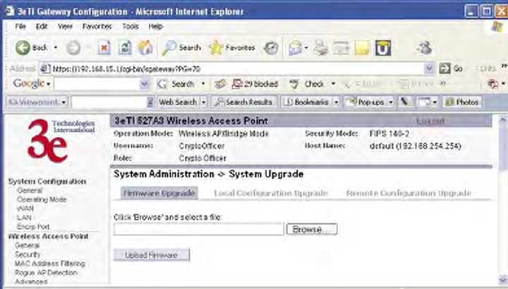
3e–527A3 Wireless Access Point – 8 Port Chapter 3: Access Point Conguration
60 29000152-001 B
3e–527A3 Wireless Access Point – 8 Port Chapter 3: Access Point Conguration
29000152-001 B 61
System Upgrade
The System Administration — System Upgrade screen gives you the
ability to upload updates to the 3e–527A3 device’s rmware as they be-
come available. When a new upgrade le becomes available, you can do a
rmware upgrade from the Firmware Upgrade window.
There is also a conguration le transfer option which allows the
system conguration le from one AP to be transferred to another AP, in
order to minimize the administration of the APs. Only conguration pa-
rameters that can be shared between APs are downloaded in the congu-
ration le. WAN IP address, hostname, and bridge priority are not trans-
ferred in the conguration le. Click on the Local Conguration Upgrade
and Remote Conguration Upgrade tabs to perform le transfers.
Only the Crypto Ofcer role can access this function.
Firmware Upgrade
On the System Administration — System Upgrade screen, the Firm-
ware Upgrade tab is the default view.
Click browse and select the rmware le to be uploaded. Click on the
Upload Firmware button.
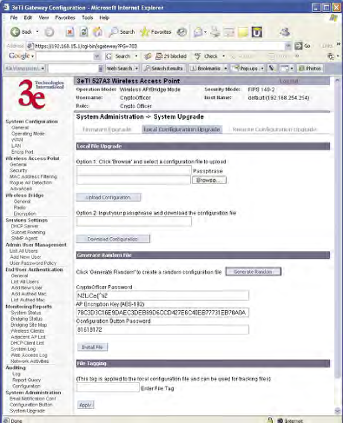
3e–527A3 Wireless Access Point – 8 Port Chapter 3: Access Point Conguration
62 29000152-001 B
3e–527A3 Wireless Access Point – 8 Port Chapter 3: Access Point Conguration
29000152-001 B 63
Local Conguration Upgrade
On the System Administration — System Upgrade screen, click on
the Local Conguration Upgrade tab to upload and download congura-
tion les to access points connected to the network.
To upload a conguration le, select the le using the browse but-
ton and enter the passphrase for that le. The passphrase protects the le
from unauthorized users. It prevents unauthorized users from applying
the system conguration le to an unauthorized AP to gain access to the
network. Before downloading the system conguration le to a local com-
puter, the user must enter a passphrase to protect the le. Before the sys-
tem conguration le can be uploaded onto another AP, the passphrase
must be entered on the remote AP.
The conguration le can be tagged with a 12 character tag to keep
track of the conguration le as it is transferred to other APs.
3e–527A3 Wireless Access Point – 8 Port Chapter 3: Access Point Conguration
62 29000152-001 B
3e–527A3 Wireless Access Point – 8 Port Chapter 3: Access Point Conguration
29000152-001 B 63
The random conguration feature is intended to reduce the effort to
generate new keys for the system and to create a new password for the
CryptoOfcer role that is performing this operation. When the generate
button is pushed, the following parameters are randomized:
• AD SSID
• AP encryption key (AES-192)
• Bridge SSID
• Bridge encryption key (AES-192)
• Bridge channel (802.11a, random channel in 5.8GHz band)
• DSL encryption key (AES-192)
• Conguration button password
• CryptoOfcer password
The following parameters are set:
• Bridge mode: auto
• Bridge radio: freq=11a, txpower=auto, broadcasting ssid=disabled
• AP radio: txpower=auto, broadcasting ssid=disabled
All other system parameters are unchanged.
IMPORTANT: The three elds that are listed (CryptoOfcer Pass-
word, AP Encryption Key, and Conguration Password Button) should be
recorded since they won't be visible after reboot. Once you record these
values, the le can be installed by clicking on the "Install le" button. The
new le will be installed and the unit will reboot.
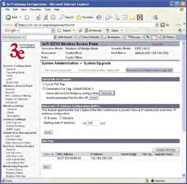
3e–527A3 Wireless Access Point – 8 Port Chapter 3: Access Point Conguration
64 29000152-001 B
3e–527A3 Wireless Access Point – 8 Port Chapter 3: Access Point Conguration
29000152-001 B 65
Remote Conguration Upgrade
On the System Administration — System Upgrade screen, click on
the Remote Conguration Upgrade tab to upload and download cong-
uration les to access points in remote locations which are not congured.
This remote conguration upgrade feature allows you to selectively
transfer a conguration le to other APs. Once the le is transferred, the
remote AP will be rebooted. Once the remote units are rebooted, the site
map can be updated and the File Tag will show the status of the units. If
the tag matches the local tag, the unit was updated successfully.
While les are being transferred press the F5 key to see the status of
the transfer. Pressing F5 will update the status only, not the entire page.
The status will either be "le sent", "upgrading", successful", or "failure".
If you click on the Update Site Map button then the status of the transfer
will be lost.
Two types of les can be transferred, a local le or a randomly gener-
ated le. A local le is the current conguration that is running on the AP.
A randomly generated le is the local le with a randomly selected bridg-
ing SSID and a randomly selected bridging encryption key (AES-192).
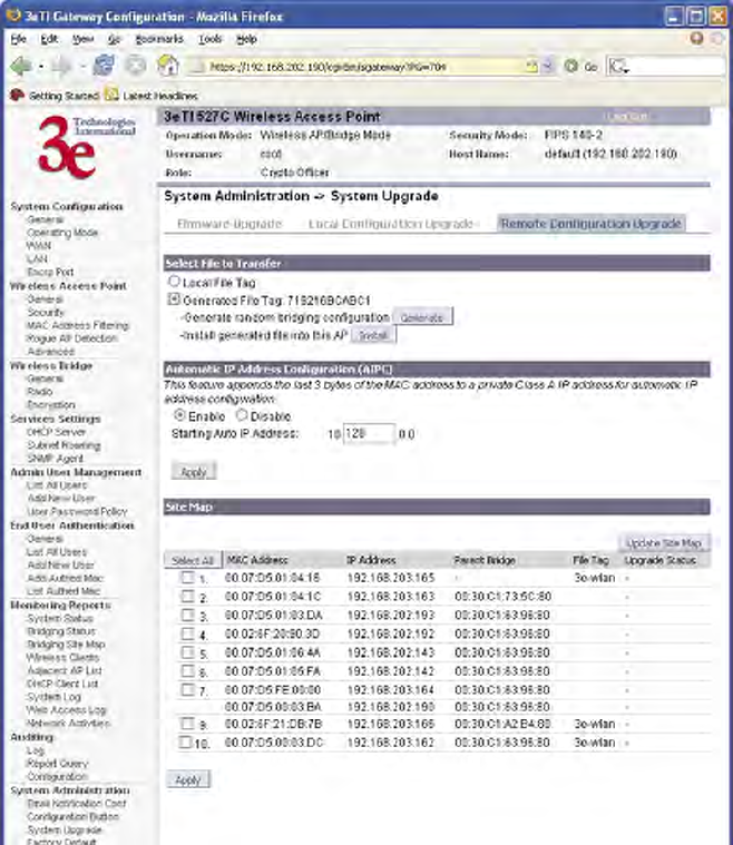
3e–527A3 Wireless Access Point – 8 Port Chapter 3: Access Point Conguration
64 29000152-001 B
3e–527A3 Wireless Access Point – 8 Port Chapter 3: Access Point Conguration
29000152-001 B 65
The random conguration le is used to update the bridging SSID
and bridging encryption on other devices using the existing bridging
link. If the bridging key or the bridging SSID is changed on the normal
conguration screen, then the bridging link to the other devices will be
terminated, and the conguration can not be updated.
To create a randomly generated bridging conguration le, click
Generate. A new conguration is created in a temporary le and an
Install button appears. In order to transfer this le, select the Generated
File radio button, check the desired recipients in the Site Map section, and
click Apply. After the le has been successfully transferred to the recipi-
ents (check the status eld in the lower section), click Install to apply the
randomly generated conguration le to the AP. Once applied, the unit
will reboot and start using the new conguration le.
The automatic IP address conguration feature can be used to assign
a remote device an IP address. This feature minimizes the effort to con-
gure IP addresses in a wireless network. The IP addresses are assigned
on the private class A IP address range (10.0.0.0). By default, this feature
is enabled, so if you want to assign your own IP addresses you need to
disable this feature.
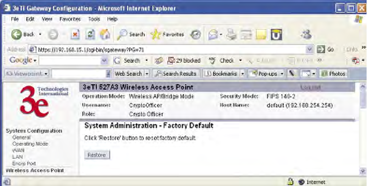
3e–527A3 Wireless Access Point – 8 Port Chapter 3: Access Point Conguration
66 29000152-001 B
3e–527A3 Wireless Access Point – 8 Port Chapter 3: Access Point Conguration
29000152-001 B 67
You have the option to congure the second byte of the IP address to
limit the range in which the IP addresses are distributed. For example, if
your network already uses the 10.0.0.0 network address for other devices,
you can limit the auto conguration to an upper range of 10.128.0.0 and
the IP addresses will start from that number.
The automatic IP address conguration feature uses the last three
bytes of the WAN MAC address for the last three bytes of the IP address.
For example, the WAN MAC address of 00:07:D5:01:02:03 will translate to
an IP address of 10.1.2.3. If the starting range of the automatic IP address
conguration is set to 10.128.0.0 and the WAN MAC address is 00:07:D5:
01:02:03, then the IP address is pushed to the upper range and becomes
10.129.2.3 (basically the second byte adds 128+1). The MAC addresses on
the WAN port are from the 3eTI's address pool of 16 million addresses.
There is a small chance for duplicate MACs. However, if a duplicate IP
address is detected, the bridge site map will show this device with a red
IP address. The distributed default gateway is the rst IP address in the
valid range. For example: for 10.128.0.0, the default gateway is 10.128.0.1.
The distributed netmask is 255.0.0.0.
Factory Default
The System Administration — Factory Default screen is used to reset
the AP to its factory settings.
The "Restore" button is a fallback troubleshooting function that should
only be used to reset to original settings.
Only the Crypto Ofcer role has access to the Restore button.
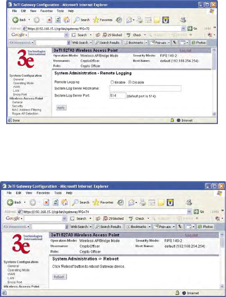
3e–527A3 Wireless Access Point – 8 Port Chapter 3: Access Point Conguration
66 29000152-001 B
3e–527A3 Wireless Access Point – 8 Port Chapter 3: Access Point Conguration
29000152-001 B 67
Remote Logging
The System Administration —Remote Logging screen allows you to
forward the syslog data from each machine to a central remote logging
server. In the 3e–527A3, this function uses the syslogd daemon. If you en-
able Remote Logging, input a System Log Server IP Address and System
Log Server Port. Click Apply to accept these values.
Reboot
The System Administration — Reboot screen allows you to reboot
the 3e–527A3 without changing any preset functionality. Both Crypto Of-
cer and Administrator functions have access to this function.
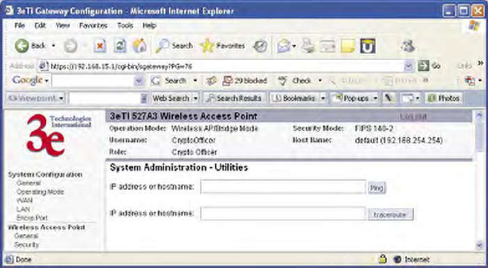
3e–527A3 Wireless Access Point – 8 Port Chapter 3: Access Point Conguration
68 29000152-001 B
Utilities
The System Administration — Utilities screen gives you ready access
to two useful utilities: Ping and Traceroute. Simply enter the IP Address
or hostname you wish to ping or traceroute and click either the Ping or
Traceroute button, as appropriate.

3e–527A3 Wireless Access Point – 8 Port Chapter 4: Gateway Conguration
29000152-001 B 69
Caution: If you have previously set up your WLAN using
the 3e–527A3 devices as access points and you decide to change
the conguration to gateway mode, you will need to convert
the MAC addresses on each wireless device that has been set
up so they can be seen by the recongured system. This is ac-
complished by the following procedure, done on each device
that was congured to use the 3e–527A3 when the system was
set up as an access point system. Pull up a System Prompt (“c:\”
prompt, also called an MSDOS prompt) on the wireless device’s
desktop. type: arp -d and hit return. This recongures the MAC
address in the wireless device’s PC card so that it is now visible
to the gateway.
Chapter 4: Gateway Conguration
Introduction
Chapter 3 covered the default conguration of the 3e–527A3 Wireless
Access Point as an access point, for use as part of a host wired network.
This chapter covers conguration as a gateway.
If additional security for the wireless network is desired (differen–
tiating it from the wired network to which it is connected), set it up in
gateway mode. Gateway mode takes advantage of some built-in “router”
functions, such as the gateway’s ability to do Network Address Transla-
tion (NAT), providing private IP addresses for the wireless clients.
The illustration on the following page shows the difference between
AP and Gateway mode.
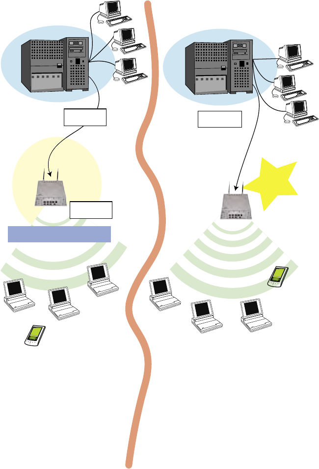
3e–527A3 Wireless Access Point – 8 Port Chapter 4: Gateway Conguration
70 29000152-001 B
3e–527A3 Wireless Access Point – 8 Port Chapter 4: Gateway Conguration
29000152-001 B 71
A comparison of gateway and access point setup
for the 3e–527A3
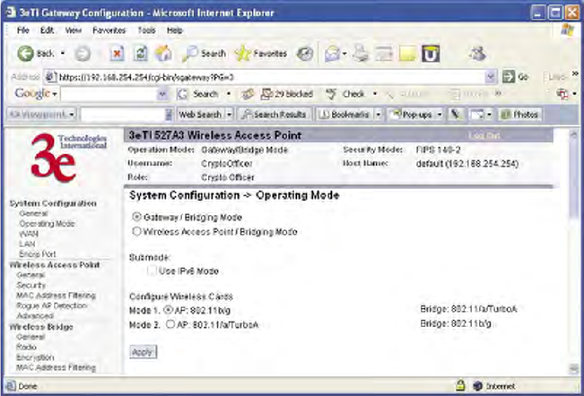
3e–527A3 Wireless Access Point – 8 Port Chapter 4: Gateway Conguration
70 29000152-001 B
3e–527A3 Wireless Access Point – 8 Port Chapter 4: Gateway Conguration
29000152-001 B 71
Conguring in Gateway Mode
To congure the 3e–527A3 in gateway mode, complete the following
steps.
1. Login on to the 3e–527A3 (see Chapter 3, page 21).
2. Using the navigation bar to the left, navigate to the System Con-
guration — Operating Mode screen, select the Gateway Mode
radio button, and click Apply. The 3e–527A3 AP will reboot in
gateway mode.
Note that if you change modes from AP to Gateway, your congura-
tion is not lost.
You can then proceed to change the management screens as necessary
to recongure the device as a gateway. Conguration in gateway mode
allows you to set rewall parameters. This is the main difference between
the screens you will see in gateway mode and those covered in access
point setup as discussed in Chapter 3.
The following sections only cover the functions and screens that are
unique to the gateway mode. All of the screens that are common to both
the AP and Gateway modes are covered in Chapter 3.
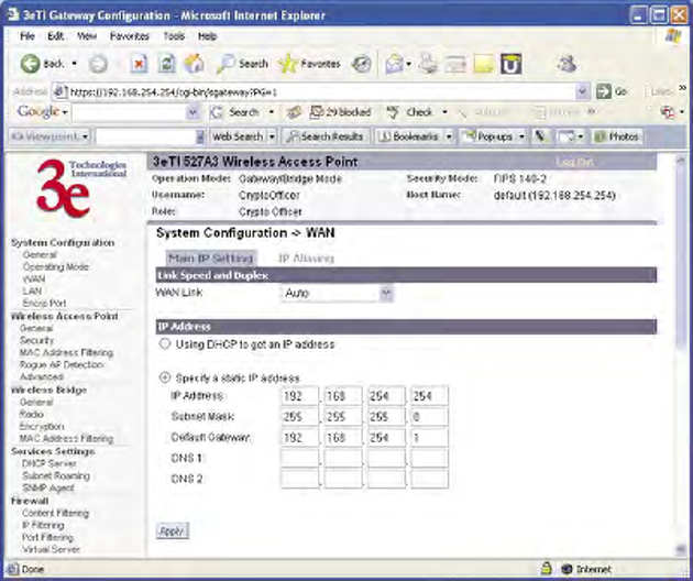
3e–527A3 Wireless Access Point – 8 Port Chapter 4: Gateway Conguration
72 29000152-001 B
3e–527A3 Wireless Access Point – 8 Port Chapter 4: Gateway Conguration
29000152-001 B 73
WAN
In Gateway mode, the System Conguration–WAN screen has two
tabs: Main IP Setting and IP Aliasing.
Main IP Setting
The Main IP Setting screen allows you to set Link Speed and Duplex
of the WAN port. If you select a choice other than Auto (the default),
the 3e–527A3 will use only the selected link speed (10 Mbits/sec or 100
Mbits/sec) and Duplex (Half Duplex transfers or Full Duplex transfers)
that you select in the WAN/LAN Link drop-down menu.
You also set information for how the IP address will be obtained.
The WAN IP address is the Public IP address required to link the pri-
vate WLAN users to the external enterprise or shipboard network, which
is to be outside the “protected” wireless LAN. Normally, you will be
provided with the IP address, Subnet Mask, Default Gateway and DNS
to assign by the Network Administrator for the Ethernet Network.
There are two ways to congure the WAN IP address:
1. Obtain an IP address Automatically – This conguration allows
the Ethernet network to use the DHCP server on the wired net-
work to dynamically assign the WAN IP address to the DHCP
client in the gateway.
2. Specify an IP address – This conguration allows the user to
manually type in a static IP address, default gateway, and Domain
Name Server (DNS) if these are provided by the Ethernet network
administrator.
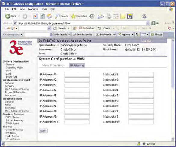
3e–527A3 Wireless Access Point – 8 Port Chapter 4: Gateway Conguration
72 29000152-001 B
3e–527A3 Wireless Access Point – 8 Port Chapter 4: Gateway Conguration
29000152-001 B 73
IP Aliasing
You can add up to ten additional IP aliases on the WAN port.
The IP aliasing entries can be used by the virtual server to map a
public IP address to a private IP address. If the virtual server needs to
map multiple public IP addresses to multiple private Ip addresses, the IP
aliasing entries can be used to create additional public IP addresses. These
entries are always static entries and can not use DHCP.
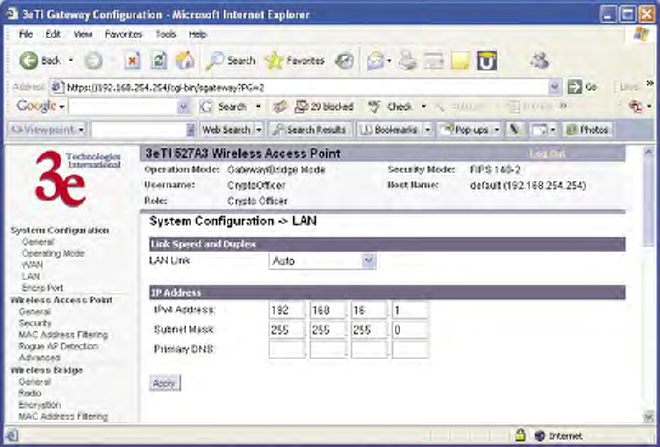
3e–527A3 Wireless Access Point – 8 Port Chapter 4: Gateway Conguration
74 29000152-001 B
3e–527A3 Wireless Access Point – 8 Port Chapter 4: Gateway Conguration
29000152-001 B 75
LAN
Click the entry on the left hand navigation panel for System Congu-
ration — LAN. This directs you to the System Conguration — LAN
screen.
This sets up the default numbers for the four octets for a possible pri-
vate LAN function for the access point. You can also change the default
subnet mask. The Local LAN port provides DHCP server functionality to
automatically assign an IP address to a computer Ethernet port.
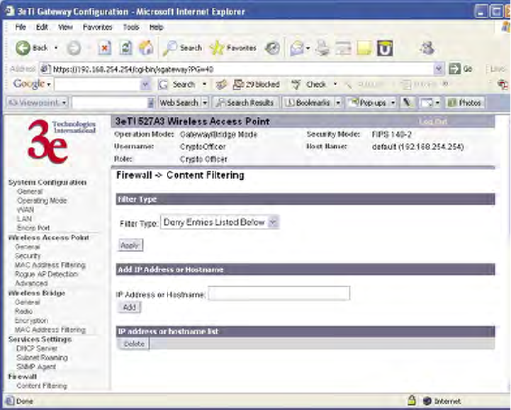
3e–527A3 Wireless Access Point – 8 Port Chapter 4: Gateway Conguration
74 29000152-001 B
3e–527A3 Wireless Access Point – 8 Port Chapter 4: Gateway Conguration
29000152-001 B 75
Security
Click the entry on the left hand navigation panel for Wireless Access
Point — Security. This directs you to the Wireless Access Point — Secu-
rity screen.
The default factory setting for the 3e–527A3 in gateway mode is no
encryption but for security reasons it will not communicate to any clients
unless the encryption is set by the CryptoOfcer. It is recommended that
you set encryption as soon as possible.
Firewall
Content Filtering
Click the entry on the left hand navigation panel for Firewall — Con-
tent Filtering. The Content Filtering screen allows the system adminis-
trator to identify particular hosts or IPs that will be blocked from access
by the gateway. Simply input the IP address and click Add.
Entries can be added as:
• Individual IP addresses (192.168.204.10)
• IP address range (192.168.204.0/24)
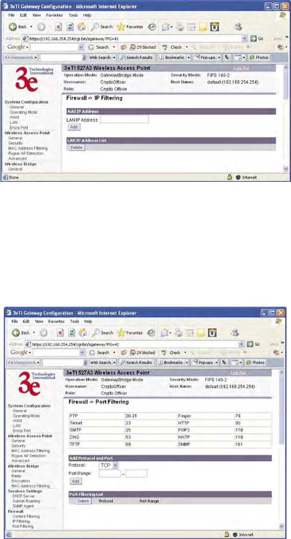
3e–527A3 Wireless Access Point – 8 Port Chapter 4: Gateway Conguration
76 29000152-001 B
3e–527A3 Wireless Access Point – 8 Port Chapter 4: Gateway Conguration
29000152-001 B 77
IP Filtering
Click the entry on the left hand navigation panel for Firewall — IP
Filtering.
The IP Filtering screen blocks certain IPs on the Private LAN from ac-
cessing your Internet connection. It restricts clients to those with a specic
IP Address.
Port Filtering
Click the entry on the left hand navigation panel for Firewall — Port
Filtering. Port ltering permits you to congure the Gateway to block
outbound trafc on specic ports. It can be used to block the wireless
network from using specic protocols on the network.
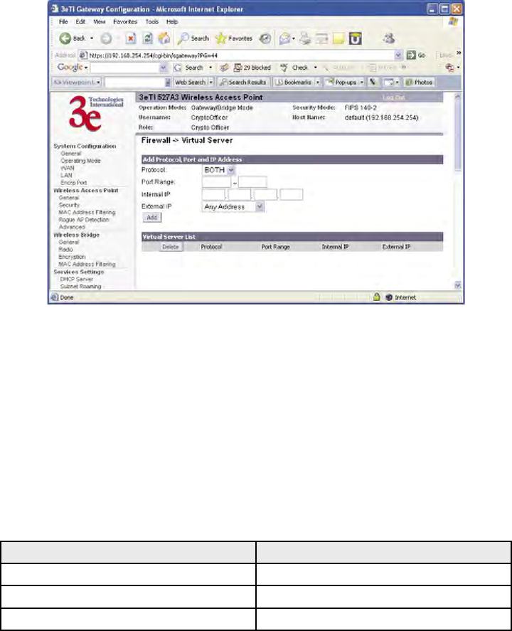
3e–527A3 Wireless Access Point – 8 Port Chapter 4: Gateway Conguration
76 29000152-001 B
3e–527A3 Wireless Access Point – 8 Port Chapter 4: Gateway Conguration
29000152-001 B 77
Virtual Server
Click the entry on the left hand navigation panel for Firewall — Vir-
tual Server.
In order to protect the Private Network, the built-in NAT rewall
lters out trafc to the private network. Since all clients on the Private
Network are normally not visible to outside users, the virtual server func-
tion allows some clients on the Private Network to be accessed by outside
users by conguring the application mapping function offered on this
page. Certain well known applications use specic TCP ports, such as
Telnet (port 23), FTP (port 21), and Web server (port 80). Client computers
on the Private LAN can host these applications, and allow users from the
Internet to access these applications hosted on the virtual servers.
This is done by mapping virtual servers to private IP addresses,
according to the specic TCP port application. As the planning table
below shows, we have identied a Telnet (port 23) virtual server for
private IP 192.168.15.56, a SMTP Mail (port 25) virtual server for pri-
vate IP 192.168.15.33, and a Web (port 80) virtual server for private IP
192.168.15.64. For example, all Internet requests to the gateway for SMTP
Mail services (port 25) to the WAN IP address will redirected to the Pri-
vate Network computer specied by the server IP 192.168.15.33.
Service Port Server IP
23 192.168.15.56
25 192.168.15.33
80 192.168.15.64
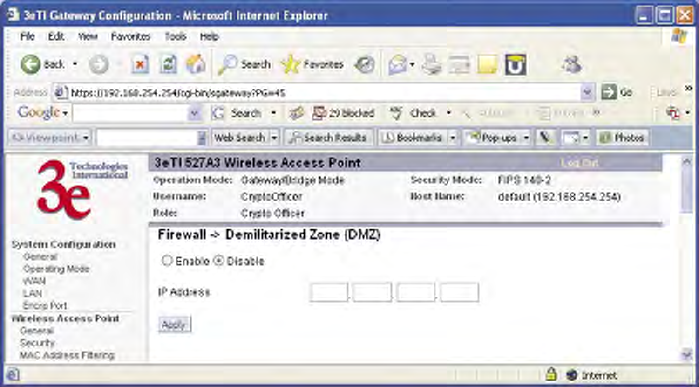
3e–527A3 Wireless Access Point – 8 Port Chapter 4: Gateway Conguration
78 29000152-001 B
3e–527A3 Wireless Access Point – 8 Port Chapter 4: Gateway Conguration
29000152-001 B 79
It is recommend that IP addresses of virtual server computers hosted
on the Private Network be manually (statically) assigned to coincide with
a static server mapping to that specic IP address. Virtual servers should
not rely on the dynamic IP assignment of the DHCP server function
which could create unmapped IP address assignments.
Protocol – Selection of either UDP, TCP, or Both (TCP and UDP) al-
lows these specied network protocols to pass through during the TCP
port communication with each virtual server IP address.
Demilitarized Zone (DMZ)
Click the entry on the left hand navigation panel for Firewall —
DMZ.
The Demilitarized Zone (DMZ) host allows one computer on the
Private Network to be totally exposed to the wired network or Internet
for unrestricted two-way communication. This conguration is typically
used when a computer is operating a proprietary client software or 2-way
communication such as video-teleconferencing, where multiple TCP port
assignments are required for communication. To assign a PC the DMZ
host status, ll in the Private IP address which is identied as the exposed
host and click the Apply button. However, any Internet user who knows
the WAN IP address of the gateway can connect to the DMZ host since
the rewall feature is disabled for this device, causing a potential security
risk to data residing on that host.
Again, it is recommended that IP addresses of DMZ host computers
on the Private Network be manually (statically) assigned to coincide with
a static DMZ host mapping to that specic IP address. DMZ hosts should
not rely on the dynamic IP assignment of DHCP server function which
could create incorrectly mapped IP address assignments to non-DMZ
hosts.
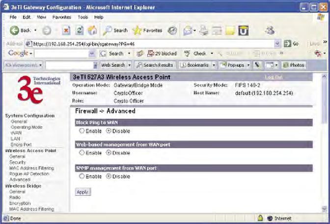
3e–527A3 Wireless Access Point – 8 Port Chapter 4: Gateway Conguration
78 29000152-001 B
3e–527A3 Wireless Access Point – 8 Port Chapter 4: Gateway Conguration
29000152-001 B 79
Advanced
Click the entry on the left hand navigation panel for Firewall — Ad-
vanced.
As advanced rewall functions, you can enable/disable
• Block Ping to WAN
• Web-based management from WAN port
• SNMP management from WAN port
These options allow you more control over your environment.
3e–527A3 Wireless Access Point – 8 Port Chapter 4: Gateway Conguration
80 29000152-001 B
This page intentionally left blank.
3e–527A3 Wireless Access Point – 8 Port Chapter 5: Wireless Bridge Conguration
29000152-001 B 81
Chapter 5: Wireless Bridge Conguration
Introduction
In the 3e–527A3, wireless bridging uses a second WLAN card to set
up an independent wireless bridge connection. Since wireless bridging
provides a mechanism for APs to collaborate, it is possible to extend the
basic service set (BSS) of a standalone AP and to connect two separate
LANs without installing any cabling.
The wireless bridging function in the 3e–527A3 supports a number of
bridging congurations. Some of the most popular settings are discussed
in this chapter:
• Point-to-point bridging of two Ethernet links
• Point-to-multipoint bridging of several Ethernet links
• Repeater mode
The wireless bridging screens are the same whether you are in access
point or gateway mode.
Bridging is a function that is set up in addition to basic access point or
gateway setup. If you will be using the 3e–527A3 solely as a bridge, some
of the settings you may have selected for access point/gateway use will
not be necessary.
If setting up as a bridge during initial setup, you can either use the
LAN Port directly wired by Ethernet cable to a laptop to set the appro-
priate settings. The management screens that you may need to modify,
regardless of what type of bridging mode you choose, will be in the Wire-
less Bridge section of the navigation bar. These include:
• Wireless Bridge — General
• Wireless Bridge — Radio
• Wireless Bridge — Encryption
• Wireless Bridge — MAC Address Filtering (Auto Mode Only)
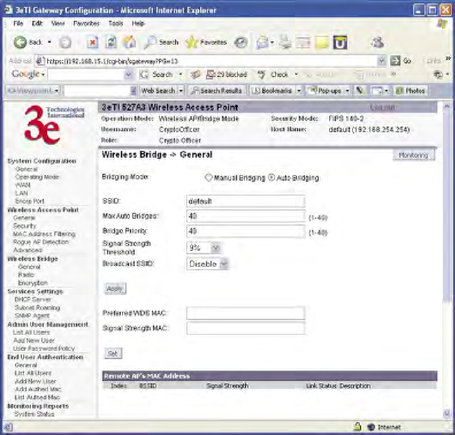
3e–527A3 Wireless Access Point – 8 Port Chapter 5: Wireless Bridge Conguration
82 29000152-001 B
3e–527A3 Wireless Access Point – 8 Port Chapter 5: Wireless Bridge Conguration
29000152-001 B 83
Wireless Bridge — General
The Wireless Bridge — General screen contains wireless bridging
information including the channel number, Tx rate, Tx power, spanning
tree protocol (802.1d) enable/disable, and remote AP's BSSID. This page
is important in setting up your bridge conguration. Wireless bridging
supports two modes of operation:
• Manual wireless bridging
• Auto-forming wireless bridging (AWB) - with a maximum num-
ber of allowable bridges (the default is 40)
Auto-forming Wireless Bridging
When the wireless bridge is in auto-forming mode, the wireless
bridge sniffs for beacons from other wireless bridges and identies APs
that match a policy such as SSID and channel.
Instead of simply adding the APs with the same SSID/channel to the
network, a three-way association handshake is performed in order to
control network access.
To make a unit the root STP node, set the bridge priority lower than
any other node in the network.

3e–527A3 Wireless Access Point – 8 Port Chapter 5: Wireless Bridge Conguration
82 29000152-001 B
3e–527A3 Wireless Access Point – 8 Port Chapter 5: Wireless Bridge Conguration
29000152-001 B 83
AUTO BRIDGING GENERAL SETTINGS OPTIONS
Bridging Mode Auto Bridging auto bridging selected
SSID numbers or letters Can be any set of letters and numbers
assigned by the network adminis-
trator. This nomenclature has to be
set on the wireless bridge and each
wireless device in order for them to
communicate.
Max Auto
Bridges
1-40 Maximum number of auto bridges
allowed.
Bridge Priority 1-40 Determines the root STP node. The
lowest bridge priority in the network
will become the STP root.
Signal Strength
Threshold
27%
21%
15%
9%
None
Prevents the node under the thresh-
old from associating and joining the
network.
Broadcast SSID Diable/Enable When disabled, the AP hides the SSID
in outgoing beacon frames and sta-
tions cannot obtain the SSID through
passive scanning.
Also, when it is disabled, the bridge
doesn’t send probe responses to probe
requests with unspecied SSIDs.
Signal Strength
MAC
The signal strength of this wireless
bridge will be indicated on the Signal
Strength LED located on the front of
the case.
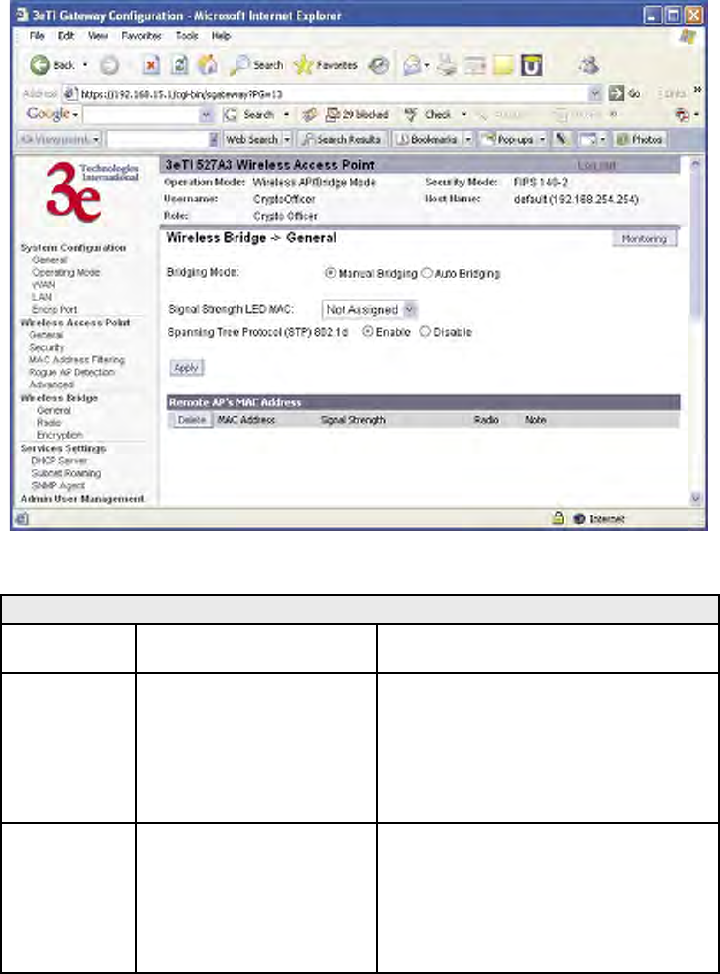
3e–527A3 Wireless Access Point – 8 Port Chapter 5: Wireless Bridge Conguration
84 29000152-001 B
3e–527A3 Wireless Access Point – 8 Port Chapter 5: Wireless Bridge Conguration
29000152-001 B 85
Manual Bridging
When the wireless bridge is in manual bridging mode, you can manu-
ally select a signal strength LED MAC and enable or disable spanning
tree protocol. You can also delete remote AP's MAC addresses.
MANUAL BRIDGING GENERAL SETTINGS OPTIONS
Bridging
Mode
Manual Bridging manual bridging selected
Signal
Strength LED
MAC
Not Assigned Allows you to set the number of one of
the Remote APs which will be listed at
the bottom of the screen once the system
is operational This wireless bridge be-
comes the guiding port that is displayed
in the WLANNSS LED on the front of
the 3e–527A3 as a signal.
Spanning Tree
Protocol (STP)
Enable/Disable Enable STP is there is any possiblity that
a bridging loop could occur. If you are
certain that there is no possibility that
a bridging loop will occur, then disalbe
STP. The bridge will be more efcient
(faster) without it. If you are not sure,
the safest solution is to enable STP.
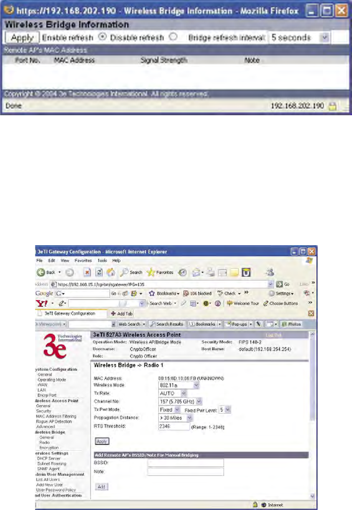
3e–527A3 Wireless Access Point – 8 Port Chapter 5: Wireless Bridge Conguration
84 29000152-001 B
3e–527A3 Wireless Access Point – 8 Port Chapter 5: Wireless Bridge Conguration
29000152-001 B 85
Monitoring
In the upper right-hand corner of the Wireless Bridge — General
screen there is a button called Monitoring. f you click on this button,
a pop-up window will appear (WDS Information). If you select En-
able refresh, you can set the bridge refresh interval from 5 seconds to 30
minutes. Refreshing the screen allows you to see the effect of aiming the
antenna to improve signal strength.
Wireless Bridge — Radio
The Wireless Bridge — Radio screen contains wireless bridging
information including the channel number, Tx rate, Tx power, spanning
tree protocol (802.1d) enable/disable, and remote AP's BSSID. This page
is important in setting up your bridge conguration.

3e–527A3 Wireless Access Point – 8 Port Chapter 5: Wireless Bridge Conguration
86 29000152-001 B
3e–527A3 Wireless Access Point – 8 Port Chapter 5: Wireless Bridge Conguration
29000152-001 B 87
Radio Settings
Wireless Mode 802.11a
802.11a Turbo
Sets the wireless mode for the wireless bridge.
Tx Rate 802.11a
AUTO,
6, 9, 12, 18, 24, 36, 48, 54
Mbps
When set to AUTO, the card attempts to select the
optimal rate for the channel. If a xed rate is used,
the card will only transmit at that rate.
802.11a Turbo
AUTO The card attempts to select the optimal rate for the
channel.
Channel No. 802.11a
149 (5.745 GHz)
153 (5.765 GHz)
157 (5.785 GHz)
161 (5.805 GHz)
165 (5.825 GHz)
Sets the channel frequency for the wireless bridge.
802.11a Turbo
152 (5.76 GHz) Turbo Mode
160 (5.80 GHz) Turbo Mode
Sets the channel frequency for the wireless bridge.
Tx Pwr Mode OFF
FIXED,
AUTO
The Tx Pwr Mode defaults to AUTO, giving the
largest range of radio transmission available under
ambient conditions.
The wireless bridge's broadcast range can be
limited by setting the Tx Pwr Mode to Fixed and
choosing from 1-5 for Fixed Pwr Level.
If you want to prevent any radio frequency trans-
mission from the wireless bridge, set the Tx Pwr
Mode to OFF. This will not turn off RF transmis-
sions from any associated wireless devices, but
they will not be able to communicate with the wire-
less bridge when the Tx Pwr Mode is off.
Fixed Pwr Level 1, 2, 3, 4, 5 Select a range when Rx Pwr Mode is set to FIXED.
Level 1 is the shortest distance (Level 1=7dBm) and
Level 5 is the longest (Level 5=15dBm)
Propagation
Distance
< 5 Miles
5-10 Miles
11-15 Miles
16-20 Miles
21-25 Miles
26-30 Miles
> 30 Miles
Set the distance based on the distance between this
bridge and furthest bridge that is connected to it.
RTS Threshold Range 1-2346 The number of bytes used for the RTS/CTS hand-
shake boundary. When a packet size is greater
than the RTS threshold, the RTS/CTS handshaking
is performed.
BSSID Enter hexadecimal num-
bers
Add the MAC address of the remote bridge. The
remote bridge's MAC address will appear at the
bottom of the screen.
Note You can enter a note that denes the location of the
remote bridge.
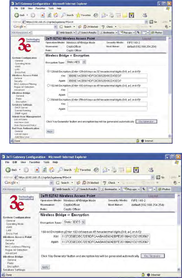
3e–527A3 Wireless Access Point – 8 Port Chapter 5: Wireless Bridge Conguration
86 29000152-001 B
3e–527A3 Wireless Access Point – 8 Port Chapter 5: Wireless Bridge Conguration
29000152-001 B 87
Wireless Bridge — Encryption
The Wireless Bridge — Encryption screen is used to congure static
encryption keys for the wireless bridge. This is an important page to set
up to ensure that your bridge is working correctly. The encryption key
that you use on this screen must be the same for any bridge connected
to your bridging network in order for communication to occur. On this
screen you can select Static 3DES ( 192-bit) or Static AES (128-bit, 192-bit,
or 256-bit).
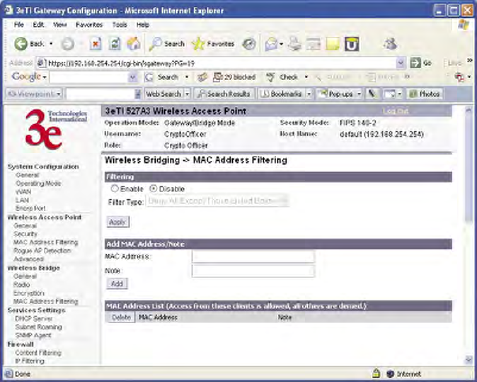
3e–527A3 Wireless Access Point – 8 Port Chapter 5: Wireless Bridge Conguration
88 29000152-001 B
3e–527A3 Wireless Access Point – 8 Port Chapter 5: Wireless Bridge Conguration
29000152-001 B 89
Wireless Bridge — MAC Address FIltering
The Wireless Bridge — MAC Address Filtering screen functions just
like the AP MAC Address Filter (see page 36) but it is only used in auto
bridging mode and only controls access to the wireless bridge network.
The following sections describe the setup for three types of bridging
conguration: point-to-point, point-to-multipoint, or, lastly, repeater.
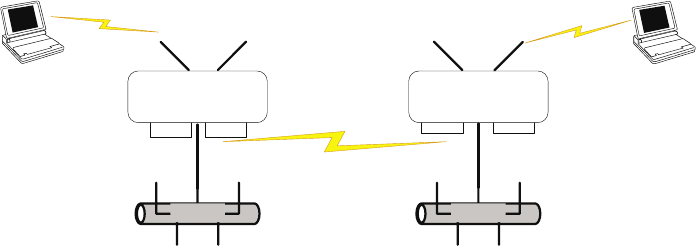
3e–527A3 Wireless Access Point – 8 Port Chapter 5: Wireless Bridge Conguration
88 29000152-001 B
3e–527A3 Wireless Access Point – 8 Port Chapter 5: Wireless Bridge Conguration
29000152-001 B 89
Setting Up Bridging Type
Point-to-Point Bridge Conguration
A point-to-point link is a direct connection between two, and only
two, locations or nodes. Because the bridge function uses a separate
WLAN card for bridging, you can also set up WLANs on the separate AP
WLAN card.
For the two bridges that are to be linked to communicate properly,
they must be set up with compatible commands in the setup screens.
For instance, the bridges must have the same channel number. Be-
cause there is a separate WLAN card for bridging, there can be a separate
WLAN on the AP WLAN card with no loss efciency, as long as you set
the channel numbers so there's no conict or noise with the channel as-
signed to the bridge. Spanning Tree Protocol may be set to Enable, if there
is any possibility of a bridging loop, or to Disable (which is more efcient)
if there's no possibility of a bridging loop. Each bridge must contain
the other's BSSID. (The BSSID of each is equivalent to the MAC address
contained on the Wireless Bridge — Radio setup page. Enter only hexa-
decimal numbers, no colons. Data entry is not case sensitive.) Finally, the
wireless bridging encryption must be set to the appropriate type and key
length and must be identical on each bridge.
The following charts show sample settings for manual bridging and
auto bridging modes.

3e–527A3 Wireless Access Point – 8 Port Chapter 5: Wireless Bridge Conguration
90 29000152-001 B
3e–527A3 Wireless Access Point – 8 Port Chapter 5: Wireless Bridge Conguration
29000152-001 B 91
Point-to-Point Bridging Setup Guide - Manual Mode
Direction Bridge 1 Bridge 2
Wireless Bridge — General (Manual Bridging Mode)
Bridging Mode manual briding selected manual bridging selected
Signal Strength LED MAC Not Assigned (select from
drop-down list)
Not Assigned (select from
drop-down list)
Spanning Tree Protocol (STP) Enable (or Disable if no
bridging loop possible)
Enable (or Disable if no
bridging loop possible)
Wireless Bridge — Radio
Wirelss Mode 802.11a 802.11a
Tx Rate AUTO AUTO
Channel No. Must be the same as
Bridge 2
Must be the same as Bridge
1
Tx Power Mode Auto Auto
Propagation Distance < 5 Miles < 5 Miles
RTS Threshold 2346 2346
BSSID Add Bridge 2 MAC Add Bridge 1 MAC
Wireless Bridge — Encryption
Bridging encryption options Select appropriate key
type/length and value.
Must be the same key as
Bridge 2.
Select appropriate key
type/length and value.
Must be the same key as
Bridge 1.
Point-to-Point Bridging Setup Guide - Auto Mode
Direction Bridge 1 Bridge 2
Wireless Bridge — Genral (Auto Bridging Mode)
Bridging Mode Auto bridging selected Auto bridging selected
SSID Must be the same as
Bridge 2
Must be the same as Bridge
1
Max Auto Bridges 40 (range 1-40) 40 (range 1-40)
Bridge Priority 40 (range 1-40) 40 (range 1-40)
Signal Strength Threshold 9% 9%
BroadcastSSID Disable Disable
Signal Strength MAC Enter from list at the bot-
tom of the screen
Enter from list at the bot-
tom of the screen
Wireless Bridge — Radio
Wirelss Mode 802.11a 802.11a
Tx Rate AUTO AUTO
Channel No. Must be the same as
Bridge 2
Must be the same as Bridge
1
Tx Power Mode Auto Auto
Propagation Distance < 5 Miles < 5 Miles
RTS Threshold 2346 2346
Wireless Bridge — Encryption
Bridging encryption options Select appropriate key
type/length and value.
Must be same as Bridge 2.
Select appropriate key
type/length and value.
Must be same as Bridge 1.
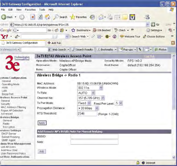
3e–527A3 Wireless Access Point – 8 Port Chapter 5: Wireless Bridge Conguration
90 29000152-001 B
3e–527A3 Wireless Access Point – 8 Port Chapter 5: Wireless Bridge Conguration
29000152-001 B 91
The following sequence walks you through the setup of bridge 1.
Bridge 2 would duplicate this procedure, with the BSSID of bridge 2 be-
ing the MAC address of bridge 1 and vice versa.
Navigate to the Wireless Bridge — Radio screen.
In the rst section you will see the MAC Address of the bridging card.
This is used as the BSSID on other 3e–527A3s that will be communicating-
with this one.
Select the Wireless Mode to be used for bridging. Set the Tx Rate to
a xed transmit rate or select AUTO if you want the card to attempt to
select the optimal rate for the channel If the Tx rate is set to a xed rate,
then the card will only transmit at that rate.
Next select the Channel Number. The Channel Number must be set
to the same frequency in order for each bridge to communicate. TX Pwr
Mode can be left on Auto unless the power needs to be regulated.
Select the Propagation Distance which is based on the distance be-
tween a bridge and the furthest bridge that is connected to it.
Set the RTS Threshold which is the number of bytes used for the
RTS/CTS handshake boundary. When a packet size is greater than the
RTS threshold, the RTS/CTS handshaking is performed.
Click Apply to accept your changes but stay on this screen.
Add the BSSID of the remote bridge. The BSSID corresponds to that
bridge’s MAC address. In entering the BSSID, enter only hexadecimal
numbers, no colons. Data entry is not case sensitive. You may also enter
a note that denes the location of the remote bridge. Then click Add to
accept. The remote bridge’s BSSID will now appear at the bottom of the
Wireless Bridge — General screen.
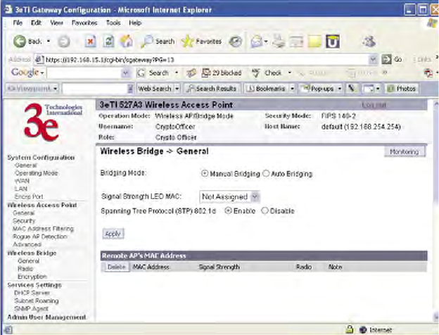
3e–527A3 Wireless Access Point – 8 Port Chapter 5: Wireless Bridge Conguration
92 29000152-001 B
3e–527A3 Wireless Access Point – 8 Port Chapter 5: Wireless Bridge Conguration
29000152-001 B 93
Next go to the Wireless Bridge — General screen. Select either
manual or auto bridging. If you choose Manual Bridging then you will
have to set Spanning Tree Protocol to Enable unless you are sure that
there is no chance of a loop. You can also assign a Signal Strength LED
MAC. Signal strength LED MAC allows you to set the number of one of
the Remote APs which will be listed at the bottom of the screen once the
system is operational as the guiding port that you wish to have display in
the WLANSS LED on the front of the 3e–527A3 as a signal. If you don’t
assign one, the LED will show the upper link signal strength (if there is
one). From this screen you can also choose to delete a remote AP's MAC
address.
Click Apply to accept your changes.
If you choose Auto Bridging mode, then you will need to enter the
follwoing information:
Enter the SSID. This can be any set of letters and numbers assigned
by the network administrator. This nomenclature has to be set on the
wireless bridge and each wireless device in order for them to communi-
cate.
Enter a number from 1 to 40 for the Max Auto Bridges. Next enter the
Bridge Priority (range from 1-40). This determines the root STP node. The
lowest bridge priority in the network will become the STP root.
Select the Signal Strength Threshold.
Either enable or disable the Broadcast SSID. When disabled, the
bridge hides the SSID in outgoing beacon frames and stations cannot
obtain the SSID through passive scanning. Also, when it is disabled, the
bridge doesn’t send probe responses to probe requests with unspecied
SSIDs.
Finally enter the Signal Strength MAC. The signal strength of this
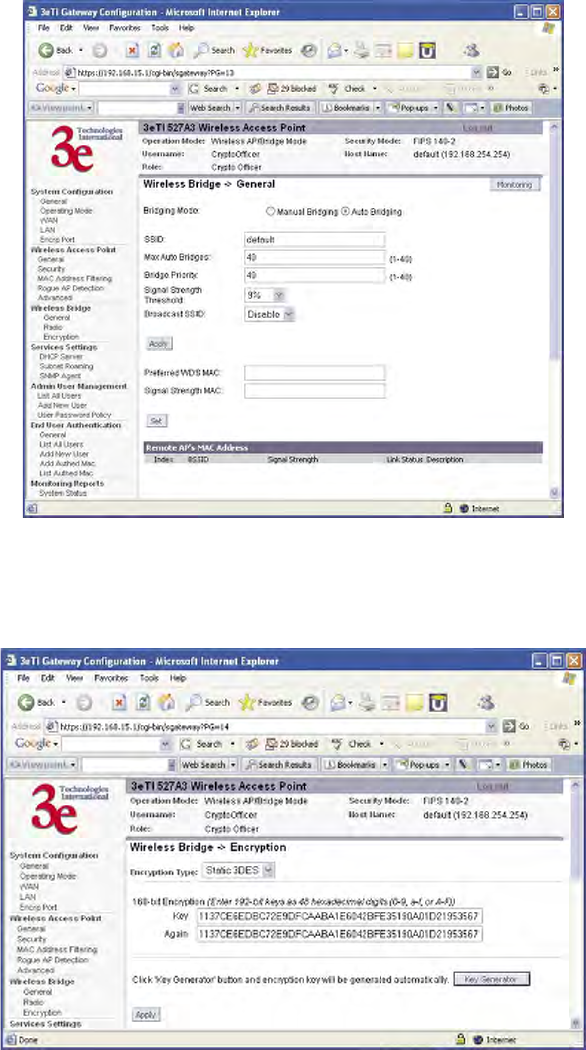
3e–527A3 Wireless Access Point – 8 Port Chapter 5: Wireless Bridge Conguration
92 29000152-001 B
3e–527A3 Wireless Access Point – 8 Port Chapter 5: Wireless Bridge Conguration
29000152-001 B 93
wireless bridge will be indicated on the Signal Strength LED located on
the front of the case.
Next, navigate to the Wireless Bridge — Encryption screen. Select
the appropriate key type and length and the key value. The encryption
key value and type for Bridge 1 must be the same as for Bridge 2. For
wireless bridging, only AES and 3DES are available for encryption.
You must complete the conguration of your Bridge 1 by following
the general instructions in Chapter 3 of this guide to establish any other
required conguration options such as General, WAN and LAN settings.
Congure the second of your two point-to-point bridges following the
instructions given for Bridge 1 above.
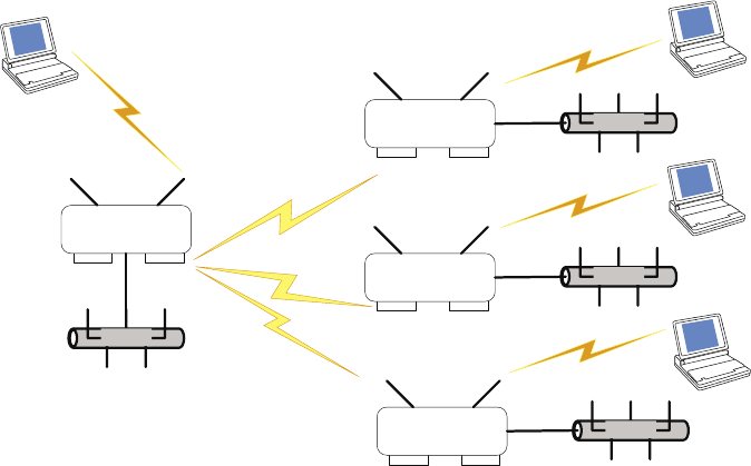
3e–527A3 Wireless Access Point – 8 Port Chapter 5: Wireless Bridge Conguration
94 29000152-001 B
3e–527A3 Wireless Access Point – 8 Port Chapter 5: Wireless Bridge Conguration
29000152-001 B 95
Point-to-Multipoint Bridge Conguration
A point-to-multipoint conguration allows you to set up three or
more 3e–527A3 access points in bridging mode and accomplish bridging
between 3 or more locations wirelessly.
For the three bridges that are to be linked to communicate properly,
they have to be set up with compatible commands in their setup screens.
For instance, all bridges must have the same channel number. Span-
ning Tree Protocol will usually be set to Enable. If congured as in the
diagram following, Bridge 1 must contain all of the others' BSSIDs, while
Bridge 2 ~ n must only contain Bridge 1's BSSID. (The BSSID of each is
equivalent to the MAC address found on the Wireless Bridge — Radio
page. Enter only hexadecimal numbers. Data entry is not case sensitive.)
Finally, the wireless bridging encryption of each must be set to the appro-
priate type and key length and must be the same on all.
Because the 3e–527A3 has two separate WLAN cards, one for the AP
and one for the Bridge, each bridge can have a WLAN on the 802.11a pro-
tocol with no loss of efciency in bridging if you wish.
The following diagram pictures a point-to-multipoint setup, which
might be of use where a company's network spans several buildings
within a campus-like setting.
Follow the steps of the procedure outlined in the point-to-point bridge
section. The chart following describes the basic attributes.

3e–527A3 Wireless Access Point – 8 Port Chapter 5: Wireless Bridge Conguration
94 29000152-001 B
3e–527A3 Wireless Access Point – 8 Port Chapter 5: Wireless Bridge Conguration
29000152-001 B 95
Point-to-Multipoint Bridging Setup Guide - Manual Mode
Direction Bridge 1 Bridge 2 ~ n
Wireless Bridge — Radio
Wirelss Mode 802.11a 802.11a
Tx Rate AUTO AUTO
Channel No. Same as Bridge 2~n Same as Bridge 1
Tx Power Mode Auto Auto
Propagation Distance < 5 Miles < 5 Miles
RTS Threshold 2346 2346
BSSID Add Bridge 2~n MAC Add Bridge 1 MAC
Wireless Bridge — General (Manual Bridging Mode)
Bridging Mode manual bridging selected manual bridging selected
Signal Strength LED MAC Not Assigned (select from
drop-down list)
Not Assigned (select from
drop-down list)
Spanning Tree Protocol Enable (or Disable if no
bridging loop possible)
Enable (or Disable if no
bridging loop possible)
Wireless Bridge — Encryption
Bridging encryption options Select appropriate key
type/length and value.
Must be the same key as
Bridge 2~n.
Select appropriate key
type/length and value.
Must be the same key as
Bridge 1.
Point-to-Multipoint Bridging Setup Guide - Auto Mode
Direction Bridge 1 Bridge 2 ~ n
Wireless Bridge — Radio
Wirelss Mode 802.11a 802.11a
Tx Rate AUTO AUTO
Channel No. Same as Bridge 2~n Same as Bridge 1
Tx Power Mode Auto Auto
Propagation Distance < 5 Miles < 5 Miles
RTS Threshold 2346 2346
BSSID Add Bridge 2~n MAC Add Bridge 1 MAC
Wireless Bridge — General (Auto Bridging Mode)
Bridging Mode Auto bridging selected Auto bridging selected
SSID Must be the same as
Bridge 2~n
Must be the same as Bridge 2
Max Auto Bridges 40 (range 1-40) 40 (range 1-40)
Bridge Priority 40 (range 1-40) 40 (range 1-40)
Signal Strength Threshold 9% 9%
Signal Strength MAC Enter from list at the bot-
tom of the screen
Enter from list at the bottom
of the screen
Wireless Bridge — Encryption
Bridging encryption options Select appropriate key
type/length and value.
Must be same as Bridge 2.
Select appropriate key type/
length and value. Must be
same as Bridge 1.
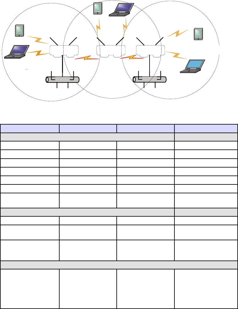
3e–527A3 Wireless Access Point – 8 Port Chapter 5: Wireless Bridge Conguration
96 29000152-001 B
3e–527A3 Wireless Access Point – 8 Port Chapter 5: Wireless Bridge Conguration
29000152-001 B 97
The above recommended setup requires only Bridge 1 to be set in
point-to-multipoint mode. It is possible to set all bridges in point-to-
multipoint mode, in which case , each bridge would have to contain the
BSSID for each of the other bridges and Spanning Tree Protocol must be
Enabled. Complete any other setup screens following general instructions
in Chapter 3.
Repeater Bridge Conguration
A repeater setup can be used to extend the wireless signal from one
bridge connected to an Ethernet LAN wirelessly so that another bridge
can control a wireless LAN at a distance.
Repeater Bridging Setup Guide - Manual Mode
Direction Bridge 1 Bridge 2 Bridge 3
Wireless Bridge — Radio
Wireless Mode 802.11a 802.11a 802.11a
Tx Rate AUTO AUTO AUTO
Channel No. Same as Bridge 2 Same as Bridge 1 Same as Bridge 1
Tx Power Mode Auto Auto Auto
Propagation Distance < 5 Miles < 5 Miles < 5 Miles
RTS Threshold 2346 2346 2346
BSSID Add Bridge 2's MAC Add Bridge 1's and
Bridge 3's MAC
Add Bridge 2's MAC
Wireless Bridge — General (Manual BridgingMode)
Bridging Mode manual manual manual
Signal Strength LED
MAC
Not Assigned (select
from drop-down list)
Not Assigned (select
from drop-down list)
Not Assigned (select
from drop-down list)
Spanning Tree Pro-
tocol
Enable (or Disable
if no bridging loop
possible)
Enable (or Disable
if no bridging loop
possible)
Enable (or Disable if no
bridging loop possible)
Wireless Bridge — Encyption
Wireless Congu-
ration – Bridging
Encryption
Select appropriate
key type/length
and enter key value.
Must be the same as
that on the other two
Bridges.
Select appropriate
key type/length
and enter key value.
Must be the same as
that on the other two
Bridges.
Select appropriate key
type/length and enter
key value. Must be the
same as that on the
other two Bridges.

3e–527A3 Wireless Access Point – 8 Port Chapter 5: Wireless Bridge Conguration
96 29000152-001 B
3e–527A3 Wireless Access Point – 8 Port Chapter 5: Wireless Bridge Conguration
29000152-001 B 97
Repeater Bridging Setup Guide - Auto Mode
Direction Bridge 1 Bridge 2 Bridge 3
Wireless Bridge — Radio
Wireless Mode 802.11a 802.11a 802.11a
Tx Rate AUTO AUTO AUTO
Channel Same as Bridge 2 Same as Bridge 1 Same as Bridge 1
Tx Power Mode Auto Auto Auto
Propagation Dis-
tance
< 5 Miles < 5 Miles < 5 Miles
RTS Threshold 2346 2346 2346
BSSID Add Bridge 2's
MAC
Add Bridge 1's and
Bridge 3's MAC
Add Bridge 2's
MAC
Wireless Bridge — General (Auto Bridging Mode)
Bridging Mode auto auto auto
SSID Must be the same as
Bridge 2
Must be the same as
Bridge 1
Must be the same
as Bridge 1
Max Auto Bridges 40 (range 1-40) 40 (range 1-40) 40 (range 1-40)
Bridge Priority 40 (1-40) 40 (1-40) 40 (1-40)
Signal Strength
Threshold
9% 9% 9%
Signal Strength
MAC
Enter from list at
the bottom of the
screen
Enter from list at the
bottom of the screen
Enter from list at
the bottom of the
screen
Wireless Bridge — Encyption
Wireless Congu-
ration – Bridging
Encryption
Select appropriate
key type/length
and enter key
value. Must be the
same as that on the
other 2 Bridges.
Select appropriate
key type/length
and enter key value.
Must be the same as
that on the other 2
Bridges.
Select appropriate
key type/length
and enter key
value. Must be the
same as that on the
other 2 Bridges.
With this conguration, each bridge can control a wireless LAN. All
wireless clients must have the same SSID as the bridges on the AP card
channel. All clients can roam between the three bridges.
All other setup screens should be completed following the guidelines
in Chapter 3.
3e–527A3 Wireless Access Point – 8 Port Chapter 5: Wireless Bridge Conguration
98 29000152-001 B
This page intentionally left blank.
3e–527A3 Wireless Access Point – 8 Port Chapter 6: Technical Support
29000152-001 B 99
Chapter 6: Technical Support
Manufacturer’s Statement
The 3e–527A3 is provided with warranty. It is not desired or expected
that the user open the device. If malfunction is experienced and all exter-
nal causes are eliminated, the user should return the unit to the manufac-
turer and replace it with a functioning unit.
If you are experiencing trouble with this unit, the point of contact is:
support@3eti.com
1-800-449-3384 (Monday - Friday, 8am to 5pm EST)
or visit our website at
www.3eti.com
Radio Frequency Interference Requirements
This device has been tested and found to comply with the limits for a
Class A digital device, pursuant to Part 15 of the Federal Communications
Commission’s Rules and Regulations. These limits are designed to pro-
vide reasonable protection against harmful interference when the equip-
ment is operated in a commercial environment. This equipment gener-
ates, uses, and can radiate radio frequency energy and, if not installed
and used in accordance with the instruction manual, may cause harmful
interference to radio communications. Operation of this equipment in a
residential area is likely to cause harmful interference in which case the
user will be required to correct the interference at his own expense.
Installation should be accomplished using the authorized cables
and/or connectors provided with the device or available from the
manufacturer/distributor for use with this device. Changes or modica-
tions not expressly approved by the manufacturer or party responsible for
this FCC compliance could void the user’s authority to operate the equip-
ment.
3e–527A3 Wireless Access Point – 8 Port Chapter 6: Technical Support
100 29000152-001 B
This page intentionally left blank.
3e–527A3 Wireless Access Point – 8 Port Glossary
29000152-001 B G-a
Glossary
3DES
Also referred to as Triple DES, a mode of the DES encryption algorithm that encrypts data
three times.
802.11
802.11 refers to a family of specications developed by the IEEE for wireless LAN technol-
ogy. 802.11 species an over-the-air interface between a wireless client and a base station
or between two wireless clients. The IEEE accepted the specication in 1997.
802.11b (also referred to as 802.11 High Rate or WiFi)
802.11b is an extension to 802.11 that applies to wireless LANs and provides 11 Mbps
transmission (with a fallback to 5.5, 2 and 1 Mbps) in the 2.4 GHz band. 802.11b uses only
DSSS. 802.11b was a 1999 ratication to the original 802.11 standard, allowing wireless
functionality comparable to Ethernet.
Access Point
An access point is a gateway set up to allow a group of LAN users access to another group
or a main group. The access point doesn’t use the DHCP server function and therefore ac-
cepts IP address assignment from the controlling network.
AES
Short for Advanced Encryption Standard, a symmetric 128-bit block data encryption tech-
nique developed by Belgian cryptographers Joan Daemen and Vincent Rijmen. The U.S
government adopted the algorithm as its encryption technique in October 2000, replacing
the DES encryption it used. AES works at multiple network layers simultaneously.
Bridge
A device that connects two local-area networks (LANs), or two segments of the same LAN
that use the same protocol, such as Ethernet or Token-Ring.
DHCP
Short for Dynamic Host Conguration Protocol, DHCP is a protocol for assigning dy-
namic IP addresses to devices on a network. With dynamic addressing, a device can have
a different IP address every time it connects to the network. In some systems, the device’s
IP address can even change while it is still connected. DHCP also supports a mix of
static and dynamic IP addresses. Dynamic addressing simplies network administration
because the software keeps track of IP addresses rather than requiring an administrator to
manage the task. This means that a new computer can be added to a network without the
hassle of manually assigning it a unique IP address. Many ISPs use dynamic IP addressing
for dial-up users.
NMS (Network Management Station)
Includes such management software as HP Openview and IBM Netview.
PC Card
A computer device packaged in a small card about the size of a credit card and con-
forming to the PCMCIA standard.
PDA (Personal Digital Assistant)
3e–527A3 Wireless Access Point – 8 Port Glossary
G-b 29000152-001 B
A handheld device.
SNMP
Simple Network Management Protocol
SSID
A Network ID unique to a network. Only clients and access points that share the same
SSID are able to communicate with each other. This string is case-sensitive. Wireless LANs
offer several security options, but increasing the security also means increasing the time
spent managing the system. Encryption is the key. The biggest threat is from intruders
coming into the LAN. You set a seven-digit alphanumeric security code, called an SSID, in
each wireless device and they thereafter operate as a group.
TKIP
Temporal Key Integrity Protocol. TKIP is a protocol used in WPA. It scrambles the keys
using a hashing algorithm and, by adding an integrity-checking feature, ensures that the
keys haven’t been tampered with.
VPN (Virtual Private Network)
A VPN uses encryption and other security mechanisms to ensure that only authorized us-
ers can access the network and that the data cannot be intercepted.
WLAN (Wireless Local Area Network)
A type of local-area network that uses high-frequency radio waves rather than wires to
communicate between nodes.
WPA
WPA stands for WiFi Protected Access. It’s an interim standard developed by the WiFi
Alliance pending full ratication of the 802.11i standard, to protect the wired band and
improve upon the old WEP encryption standard.