3e Technologies 531AP 802.11b Access Point User Manual Users Guide
3e Technologies International, Inc. 802.11b Access Point Users Guide
Contents
- 1. Users Guide
- 2. Access Point Users Guide
Users Guide
Wireless Access Point
User's Guide
Model 3e-531AP
3e Technologies International
700 King Farm Blvd., Rockville, MD 20850
(301) 670-6779 www.3eti.com
29000125-001 C publ. 09/29/04
This page intentionally left blank.

3e Technologies International's
Wireless Access Point
User's Guide
Model 3e-531AP
3e Technologies International
700 King Farm Blvd.
Rockville, MD 20850
(301) 670-6779 www.3eti.com
Safety Requirements
• If AC power will be used, the socket outlet
shall be installed near the equipment and
shall be easily accessible.
• CAUTION: Risk of explosion if battery is
replaced by an incorrect type. DIspose of
used batteries according to the instructions.
• External Power to Earth (PE) or ground
connector must be connecetd rst and shall
always be connected if power is applied to
the unit.
29000125-001 C iii
3e-531AP Wireless Access Point Table of Contents
Copyright © 2004 3e Technologies International. All rights reserved. No part of this documentation
may be reproduced in any form or by any means or to make any derivative work (such as translation,
transformation, or adaptation) without written permission from 3e Technologies International.
3e Technologies International reserves the right to revise this documentation and to make changes in
content from time to time without obligation on the part of 3e Technologies International to provide
notication of such revision or change.
3e Technologies International provides this documentation without warranty, term or condition
of any kind, either implied or expressed, including, but not limited to, the implied warranties,
terms, or conditions of merchantability, satisfactory quality, and tness for a particular purpose.
3e Technologies International may make improvements or changes in the product(s) and/or the
program(s) described in this documentation at any time.
If there is any software or removable media described in this documentation, it is furnished under a
license agreement included with the product as a separate document, in the printed documentation,
or on the removable media in a readable le such as license.txt or the like. If you are unable to locate a
copy of the license, contact 3e Technologies International and a copy will be provided to you.
___________________________________
UNITED STATES GOVERNMENT LEGEND
If you are a United States Government agency, then this documentation and the product described
herein are provided to you subject to the following:
All technical data and computer software are commercial in nature and developed solely at private
expense. Software is delivered as “Commercial Computer Software” as dened in DFARS 252.227-
7014 (June 1995) or as a “commercial item” as dened in FAR 2.101(a) and as such is provided with
only such rights as are provided in 3e Technologies International’s standard commercial license for
the software. Technical data is provided with limited rights only as provided in DFAR 252.227-7015
(Nov 1995) or FAR 52.227-14 (June 1987), whichever is applicable. You agree not to remove or deface
any portion of any legend provided on any licensed program or documentation contained in, or
delivered to you in conjunction with, this User Guide.
___________________________________
3e Technologies International and the 3e Technologies International logo are registered trademarks.
Windows is a registered trademark of Microsoft Corporation. Palm and Palm OS are registered
trademarks of Palm, Inc. PRISM is a registered trademark of Intersil Corporation. Samsung, CC&C
and Senao are registered trademarkes of their companies respectively.
Any other company and product name mentioned herein is a trademark of the respective company
with which they are associated.
EXPORT RESTRICTIONS
This 3e Technologies International product contains encryption and may require U.S. and/or local
government authorization prior to export to another country.
29000125-001 C iii
3e-531AP Wireless Access Point Table of Contents
Table of Contents
Chapter 1: Introduction...................................................................................................1
Basic Features .............................................................................................................2
Wireless Basics............................................................................................................3
802.11b.......................................................................................................................3
Network Conguration ..........................................................................................4
Access Point Congurations..................................................................................4
Possible AP Topologies.........................................................................................4
Gateway Congurations ........................................................................................5
Bridging Mode.........................................................................................................6
Default Conguration.............................................................................................6
Data Encryption and Security..................................................................................6
SSID ...........................................................................................................................7
AES and 3DES..........................................................................................................7
Dynamic Key Management ...................................................................................7
Authentication .........................................................................................................7
DHCP Server and NAT...........................................................................................8
Operator Authentication and Management ........................................................8
Management...............................................................................................................8
Chapter 2: Hardware Installation..................................................................................9
Preparation for Use....................................................................................................9
Installation Instructions ..........................................................................................10
Minimum System and Component Requirements ............................................10
Cabling ......................................................................................................................11
Indicator Lights......................................................................................................12
Chapter 3: Access Point Conguration .....................................................................13
Introduction ..............................................................................................................13
Preliminary Conguration Steps...........................................................................14
Initial Setup using the “Local” Port ......................................................................14
System Conguration..............................................................................................16
General....................................................................................................................16
WAN........................................................................................................................17
LAN .........................................................................................................................18
Operating Mode.....................................................................................................18
Wireless Setup ..........................................................................................................19
General....................................................................................................................19
Encryption ..............................................................................................................21
Dynamic Key Management...............................................................................21
Static 3DES Key/Open System Authentication..............................................21
Static AES Key/Open System Authentication................................................22
MAC Address Filtering ........................................................................................23
Bridging and Bridging Encryption .....................................................................23
Rogue AP Detection ..............................................................................................24
802.1x.......................................................................................................................24
Advanced................................................................................................................25
Services Settings.......................................................................................................26
DHCP Server..........................................................................................................26
Print Server.............................................................................................................26
SNMP ......................................................................................................................27
User Management....................................................................................................28
List All Users ..........................................................................................................28
Add New User .......................................................................................................28
iv 29000125-001 C
29000125-001 C v
3e-531AP Wireless Access Point Table of Contents
3e-531AP Wireless Access Point Table of Contents
Monitoring/Reports................................................................................................29
System Status .........................................................................................................29
Bridging Status.......................................................................................................30
Wireless Clients......................................................................................................30
Rogue AP List.........................................................................................................32
DHCP Client List...................................................................................................32
System Log .............................................................................................................33
Web Access Log .....................................................................................................33
Network Activites .................................................................................................34
System Administration ...........................................................................................34
Firmware Upgrade................................................................................................34
Self-Test ...................................................................................................................35
Factory Default ......................................................................................................36
Remote Logging.....................................................................................................36
Reboot .....................................................................................................................37
Utilities....................................................................................................................37
Chapter 4: Gateway Conguration .............................................................................39
Introduction ..............................................................................................................39
Conguring in Gateway Mode..............................................................................41
System Conguration..............................................................................................43
General....................................................................................................................43
WAN........................................................................................................................43
LAN .........................................................................................................................44
Operating Mode.....................................................................................................45
Wireless Conguration ...........................................................................................45
General....................................................................................................................45
Encryption ..............................................................................................................47
WEP (RC4) Data Encryption .............................................................................47
Static 3DES Key/Open System Authentication..............................................47
Static AES Key/Open System Authentication................................................48
Mac Address Filtering...........................................................................................49
Rogue AP Detection ..............................................................................................50
802.1x.......................................................................................................................50
Advanced................................................................................................................51
Services Settings.......................................................................................................52
DHCP Server..........................................................................................................52
Print Server.............................................................................................................53
SNMP Agent...........................................................................................................53
Firewall......................................................................................................................54
Content Filtering....................................................................................................54
IP Filtering ..............................................................................................................55
Port Filtering ..........................................................................................................55
Virtual Server .........................................................................................................56
Demilitarized Zone (DMZ) ..................................................................................57
Block WAN ICMP..................................................................................................58
User Management....................................................................................................58
List All Users ..........................................................................................................58
Add New User .......................................................................................................59
Monitoring/Reports................................................................................................60
System Status .........................................................................................................60
Wireless Clients......................................................................................................60
Rogue AP List.........................................................................................................61
DHCP Client List...................................................................................................61
System Log .............................................................................................................62
iv 29000125-001 C
29000125-001 C v
3e-531AP Wireless Access Point Table of Contents
3e-531AP Wireless Access Point Table of Contents
Web Access Log .....................................................................................................62
Network Activites .................................................................................................63
System Administration ...........................................................................................63
Firmware Upgrade................................................................................................63
Factory Default ......................................................................................................64
Remote Logging.....................................................................................................64
Reboot .....................................................................................................................65
Utilities....................................................................................................................65
Chapter 5: Bridge Conguration .................................................................................67
Introduction ..............................................................................................................67
Preliminary Setup ....................................................................................................67
General Bridge Setup ..............................................................................................68
Bridging Type Conguration .................................................................................71
Point-to-Point Bridge Conguration ..................................................................71
Point-to-Point Bridging Setup Guide...............................................................72
Point-to-Multipoint Bridge Conguration ........................................................75
Point-to-Multipoint Bridging Setup Guide .....................................................76
Back-to-Back Bridge Conguration ....................................................................76
Back-to-Back Bridging Setup Guide.................................................................77
Repeater Bridge Conguration ...........................................................................78
Repeater Bridging Setup Guide ........................................................................78
Chapter 6: PC Card Installation on a Laptop............................................................79
Chapter 7: The RF Manager Function ........................................................................81
Introduction ..............................................................................................................81
How to Access the RF Manager Function ............................................................82
How to Program the RF Manager .........................................................................83
Chapter 8: Network Printer Setup ..............................................................................87
Install Print Service for Unix (Windows 2000): ...................................................87
Printer Setup.............................................................................................................88
Chapter 9: Technical Support.......................................................................................93
Manufacturer’s Statement ......................................................................................93
Radio Frequency Interference Requirements.......................................................93

vi 29000125-001 B
3e-531AP Wireless Access Point Navigation Options
3e-531AP Navigation Options
Access Point Gateway
Not FIPS 140-2 FIPS 140-2 Not FIPS 140-2
System Conguration System Conguration System Conguration
General General General
WAN WAN WAN
LAN LAN LAN
Operating Mode Operating Mode Operating Mode
Wireless conguration Wireless conguration Wireless conguration
General General General
Encryption Encryption Encryption
Bridging Bridging
MAC Address Filtering MAC Address Filtering MAC Address Filtering
Rogue AP detection Rogue AP detection Rogue AP detection
802.1x 802.1x
Advanced Advanced Advanced
Services Settings Services Settings Services Settings
DHCP Server DHCP Server DHCP Server
Print Server Print Server Print Server
SNMP agent SNMP agent
Firewall Firewall Firewall
Content Filtering
IP Filtering
Port Filtering
Virtual Server
DMZ
Block WAN IP ICMP
User Management User Management User Management
List All Users List All Users List All Users
Add New User Add New User Add New User
Monitoring Reports Monitoring Reports Monitoring Reports
System Status System Status System Status
Bridging Status Bridging Status
Wireless clients Wireless clients Wireless clients
Rogue AP List Rogue AP List Rogue AP List
DHCP Client List DHCP Client List DHCP Client List
System Log System Log System Log
Web Access Log Web Access Log Web Access Log
Network Activities Network Activities Network Activities
System Administration System Administration System Administration
Firmware Upgrade Firmware Upgrade Firmware Upgrade
Self-Test
Factory Default Factory Default Factory Default
Remote Logging Remote Logging
Reboot Reboot Reboot
Utilities Utilities Utilities
3e-531AP Wireless Access Point Chapter 1: Introduction
29000125-001 C 1
Chapter 1: Introduction
This manual covers the installation and operation of the 3e Technolo-
gies International’s 3e-531AP Wireless Access Point, which conforms to
the requirements of FIPS PUB 140-2, Security Requirements for Crypto-
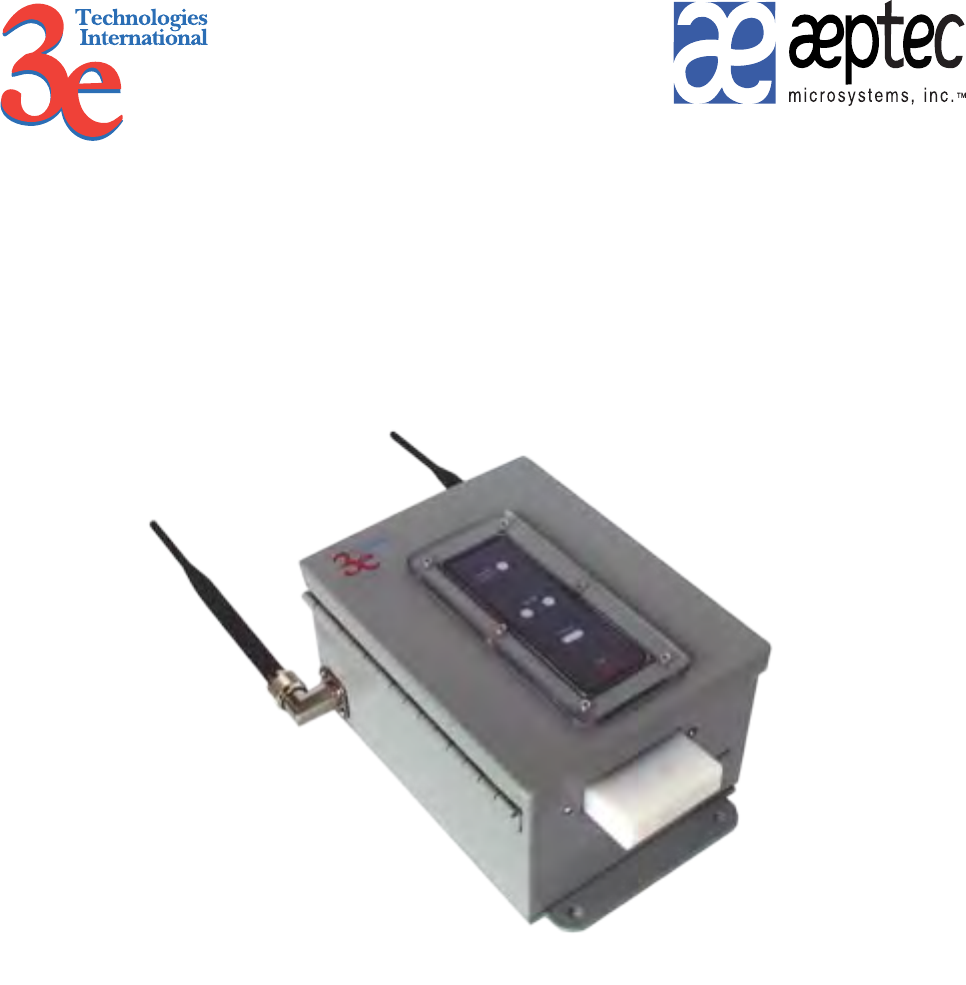
graphic Modules. The 3e-531AP Wireless Access Point provides a connec-
tion between an Ethernet LAN and a wireless LAN (WLAN). The wireless
LAN can include mobile devices such as handheld Personal Data Assis-
tants (PDAs), mobile web pads, and wireless laptops as long as they have
the 3e-010F Crypto Client software installed. (The 3e-010F Crypto Client
software is sold with the 3e-110 long range PC Card or sold separately for
use with other compatible PC Cards.)
The 3e-531AP incorporates Power over Ethernet (PoE), IEEE 802.3af,
and the highest security functionality including the ability to manage RF
centrally and to even shut off RF to wireless devices entirely, should that
be necessary. The PoE solution eliminates the need for internal gateway
power supply units (AC-DC converters) and 110-220V cabling installa-
tions for the gateway operation. In the 3e-531AP, however, the capability
to switch to AC power has been provided as a backup in the event the
Power over Ethernet hub is lost or unavailable. The device detects power
failure and automatically switches to AC current with minimal wireless
connection interruption using the power cord provided. (Note: a power
cord does not have to be plugged in to the 3e-531AP during setup, but it
is recommended that it be kept available for use in case of failure of the
PoE Power Supply.)
The PoE interface on the 3e-531AP is compatible with commercial
vendor “injected power” hub units (also known as Ethernet Power Sup-
ply or Power over Ethernet Hub) interfaces.
The 3e-531AP conforms to the FIPS 140-2 specication. It includes
the following cryptographic modules: AES/3DES for wireless encryption;
dynamic key exchange (Dife-Hellman module 1024) for wireless com-
munication; and HTTPS/TLS, for secure web communication. The 3e-
531AP contains three cryptographic modules and ports: Ethernet WAN
uplink interface for communication to the wired LAN backbone; Ethernet
LAN local port for communication to a local wired LAN; and wireless
LAN port for wireless communication to local clients. The authorized
roles supported are Crypto Ofcer Role and Administrator Role. Crypto-
graphic services provided include; AES and 3DES for wireless; SHA-1 for
authentication; HMAC SHA-1 for keyed authenticated rmware upgrade;
3e-531AP Wireless Access Point Chapter 1: Introduction
2 29000125-001 C
3e-531AP Wireless Access Point Chapter 1: Introduction
29000125-001 C 3
Dife-Hellman Key Exchange; and HTTPS/TLS for web services via a
secure link. Operator Authentication is performed by assigning operator
type: Administrator can view congurations and logs, can do non-cryp-
tographic functions such as assigning hostname, domain name, system
date/time, TX Pwr Mode/Level and the like; the Crypto Ofcer role has
total access and control and can perform cryptographic initialization or
management functions such as module initialization, input or output of
cryptographic keys and CSPs, and audit functions.
The 3e-531AP is wall-mountable and physically sealed with special
tape for physical security. Violation of the unit's integrity will cause the
unit to fail and display an Error State alarm, requiring reboot.
Basic Features
The 3e-531AP is housed in a sturdy case which is not meant to be
opened except by an authorized technician for maintenance or repair. The
unit should work without fail. If you wish to reset to factory settings, use
the reset function available through the web-screen management module.
It has the following features:
• Local Ethernet LAN
• Ethernet uplink WAN
• Wireless (802.11b) interface with operating range of 2000+ feet
• AES/3DES encryption
• HTTPS/TLS secure Web
• 802.1x/EAP-TLS
• Sealed cover with tamper-proof tape
• DHCP client/sever
• Firewall
• NAT
• Bridging Mode
• Repeater Mode
• Adjustable Radio Power
• MAC address ltering
The following cryptographic modules have been implemented in the
3e-531AP.
• AES for wireless (802.11b)
• 3DES for wireless (802.11b)
• 802.1x/EAP-TLS for authentication
• SHA-1
• HMAC SHA-1 for rmware upgrade
3e-531AP Wireless Access Point Chapter 1: Introduction
2 29000125-001 C
3e-531AP Wireless Access Point Chapter 1: Introduction
29000125-001 C 3
Wireless Basics
Wireless networking uses electromagnetic radio frequency waves to
transmit and receive data. Communication occurs by establishing radio
links between the wireless gateway and devices congured to be part of
the WLAN.
The 3e-531AP incorporates the 802.11b (Wi-Fi) standard and the most
state of the art encryption for a very powerful and secure wireless envi-
ronment.
802.11b
The IEEE 802.11b standard, developed by the Wireless Ethernet
Compatibility Alliance (WECA), establishes a stable standard. A user with
an 802.11b product can use any brand of gateway/access point with any
other brand of client hardware that is built to the 802.11b standard for ba-
sic interconnection. 802.11b devices provide 11 Mbps transmission (with a
fallback to 5.5, 2 and 1 Mbps depending on signal strength) in the 2.4 GHz
band.
802.11b uses DSSS (direct-sequence spread spectrum) for radio com-
munication. Direct-sequence systems communicate by continuously
transmitting a redundant pattern of bits called a chipping sequence. The
chipping sequence is combined with a transmitted data stream to produce
the wireless output signal.
For wireless devices to communicate with the 3e-531AP, they must
meet the following conditions:
• The signal strength must be sufcient;
• The wireless device and wireless gateway must have been cong-
ured to recognize each other using the SSID (a unique ID assigned
in setup so that the wireless device is seen to be part of the net-
work by the 3e-531AP);
• Encryption and authentication capabilities and types enabled
must conform;
• The wireless device and wireless gateway must have compatible
data rate congurations; and
• If MAC ltering is used, the 3e-531AP must be congured to
allow the wireless device’s MAC address to associate (communi-
cate) with the 3e-531AP wireless interface.
3e-531AP Wireless Access Point Chapter 1: Introduction
4 29000125-001 C
3e-531AP Wireless Access Point Chapter 1: Introduction
29000125-001 C 5
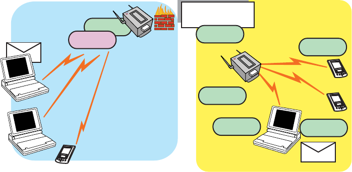
Network Conguration
The 3e-531AP is capable of various congurations. The three basic
congurations are:
• Access point mode with wired infrastructure
• Gateway mode with wired infrastructure
• Wireless bridging with choice of:
— Point-to-point setup
— Point-to-multipoint setup
— Repeater setup
Bridging actually has more choices, but the above choices are popular
and are discussed later in this user guide.
Access Point Congurations
When a 3e-531AP is congured as an access point, IP addresses for
wireless devices are typically assigned by the wired network’s DHCP
server. The wired LAN’s DHCP server assigns addresses dynamically,
and the AP virtually connects wireless users to the host wired network.
All wireless devices connected to the AP are congured on the same sub-
network as the attached wired network interface and can be accessed by
devices on the wired network.
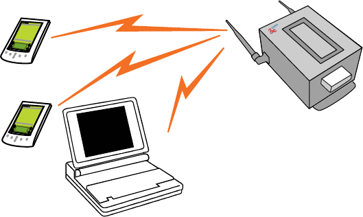
Possible AP Topologies
1. An access point can be used as a single AP without any connec-
tion to a wired network. In this conguration, it simply provides a
stand-alone wireless network for a group of wireless devices.
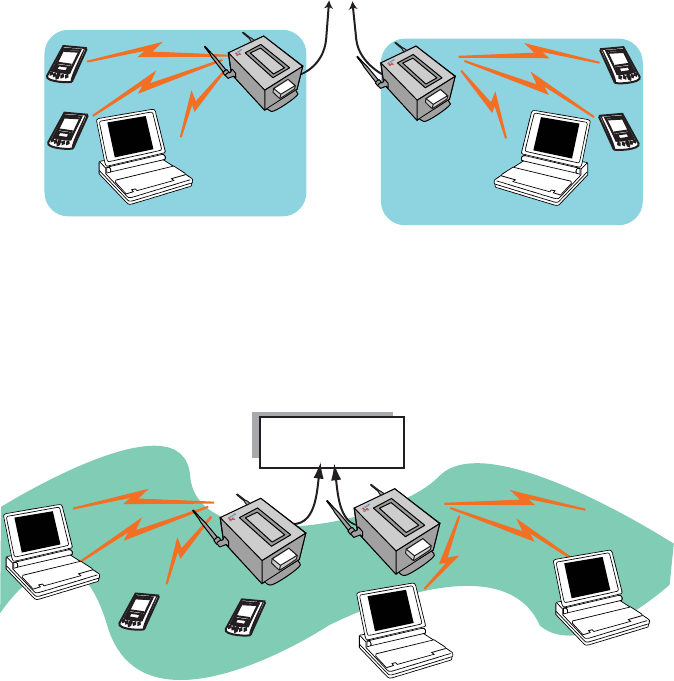
2. The 3e-531AP can be used as one of a number of APs connected
to an existing Ethernet network to bridge between the wired and
wireless environments. Each AP can operate independently of the
other APs on the LAN. Multiple APs can coexist as separate indi-
vidual networks at the same site without interference if each AP is
set with a different network ID (SSID).
3e-531AP Wireless Access Point Chapter 1: Introduction
4 29000125-001 C
3e-531AP Wireless Access Point Chapter 1: Introduction
29000125-001 C 5
3. And lastly, multiple APs connected to a wired network and operat-
ing off that network’s DHCP server can provide a wider coverage
area for wireless devices, enabling the devices to “roam” freely
about the entire site.
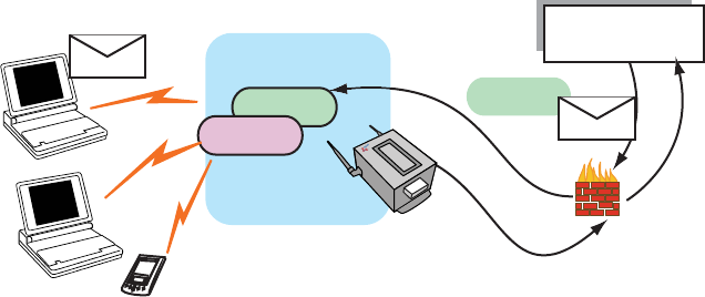
Gateway Congurations
In gateway mode, wireless users are provided additional rewall
protection from the rest of the industrial or shipboard network or Internet
using Network Address Translation (NAT) protocol features and rewall
options.
Wireless users can still communicate with the wired network resourc-
es but communication must be initiated by the wireless devices. Using the
NAT protocol, the only IP address visible to the wired network is that of
the gateway itself, as assigned by the wired Ethernet DHCP server. The
gateway provides rewall protection to its wireless users. It can dynami-
cally assign private addresses to member devices using its own internal
DHCP server. It acts as a router, not a bridge, and controls trafc ow and
access control between the wired and wireless networks.
3e-531AP Wireless Access Point Chapter 1: Introduction
6 29000125-001 C
3e-531AP Wireless Access Point Chapter 1: Introduction
29000125-001 C 7
Alternately, if you wish, the network administrator can assign static
addresses to the member wireless devices. In order to set static addresses,
the system administrator will need to manually congure the TCP/IP
conguration on each wireless device.
Bridging Mode
The wireless bridging function in the 3e-531AP allows setup as a
bridge, in a number of alternate congurations, including the following
popular congurations:
1. Point-to-point bridging of 2 Ethernet Links;
2. Point-to-multipoint bridging of several Ethernet links;
3. Repeater mode (wireless client to wireless bridge.)
Default Conguration
By default, the 3e-531AP boots up in access point mode. See your
network administrator or more advanced technical sections of this User’s
Guide for information if the device is to be congured in gateway mode
or bridging mode.
Data Encryption and Security
The 3e-531AP Wireless Access Point includes advanced wireless
security features, including Dynamic Key Management or Static key AES
or 3DES encryption. AES or 3DES and MAC Address authentication are
available in the 3e-531AP in all modes, and some level of encryption is
recommended. In gateway mode, WEP encryption is an option.
The incorporation of AES and 3DES brings system security up to the
most stringent standards. The functionality of these two enhancements,
along with a more detailed discussion of the 3e-531AP security features,
is further covered in the following paragraphs.
3e-531AP Wireless Access Point Chapter 1: Introduction
6 29000125-001 C
3e-531AP Wireless Access Point Chapter 1: Introduction
29000125-001 C 7
SSID
The Service Set ID (SSID) is a string used to dene a common roam-
ing domain among multiple wireless access points. Different SSIDs on
gateways can enable overlapping wireless networks. The SSID can act as
a basic password without which the client cannot connect to the network.
However, this is easily overridden by allowing the wireless AP to broad-
cast the SSID, which means any client can associate with the AP. SSID
broadcasting can be disabled in the 3e-531AP setup menus.
AES and 3DES
The Advanced Encryption Standard (AES) was selected by National
Institute of Standards and Technology (NIST) in October 2000 as an up-
grade from the previous DES standard. AES uses a 128-bit block cipher
algorithm and encryption technique for protecting computerized infor-
mation. It has the ability to use even larger 192-bit and 256-bit keys, if
necessary. AES is incorporated into all current and future models of 3e
Technologies International’s series of wireless APs/gateways.
3DES is also incorporated on the 3e-531AP. 3DES is modeled on the
older DES standard but encrypts data three times over. Triple-DES uses
more CPU resources than AES because of the triple encryption.
Dynamic Key Management
Addition of Security Server software (3e-030, sold separately), which
is congured to dynamically assign secure key access, raises the secu-
rity capability to its highest level. The Security Server software operates
from a remote point on the WLAN and is accessed by pointing to its IP
Address in each of the 3e-531APs on the WLAN as part of the wireless
encryption conguration process.
Authentication
The MAC address, short for Media Access Control address, is a hard-
ware address that uniquely identies each node of a network. In IEEE 802
networks, the Data Link Control (DLC) layer of the OSI Reference Model
is divided into two sub-layers: the Logical Link Control (LLC) layer and the
Media Access Control (MAC) layer. The MAC layer interfaces directly with
the network media. Consequently, each type of network media requires a
unique MAC address.
Authentication is the process of proving a client identity. The 3e-
531AP gateways, if set up to use MC address ltering, detect an attempt
to connect by a client and compare the client’s MAC address to those on
a predened MAC address lter list. Only client addresses found on the
list are allowed to associate. MAC addresses are assigned and registered
to each of the wireless cards used by the portable computing devices dur-
ing initial setup and after physical installation of the gateways.
3e-531AP Wireless Access Point Chapter 1: Introduction
8 29000125-001 C
DHCP Server and NAT
In AP mode, the 3e-531AP has a DHCP (Dynamic Host Conguration
Protocol) server function that is accessible to the LAN port. If the 3e-
531AP is set up in gateway mode, this DHCP function is available, with
many rewall functions in addition, to both the LAN and WLAN ports.
DHCP is a protocol for assigning dynamic IP addresses.
When the 3e-531AP is in access point mode, the DHCP function is
accessible only from the local LAN port. A local LAN can be established
from the LAN port and can utilize the DHCP function.
If the 3e-531AP is recongured for gateway mode, and the DHCP
function is enabled, the gateway Ethernet uplink interface becomes the
only visible IP address to the Ethernet network. It uses Network Address
Translation (NAT) to forward packets from wireless devices as if they
were coming from the one visible IP address, managing a database of in-
formation in order to sort out and forward the replies to the correct client.
NAT provides an additional layer of security by protecting information
on the wireless LAN from direct access by the Ethernet LAN.
Operator Authentication and Management
Authentication mechanisms may be required within a cryptographic
module to authenticate an operator accessing the module and to verify
that the operator is authorized to assume the requested role and perform
services within that role.
There are two types of operators dened:
• Crypto Ofcer: The Crypto Ofcer user has total control of the
gateway. The Crypto Ofcer can congure the encryption keys
and upload rmware.
• Administrator: The Administrator can view congurations and
logs, can do non-cryptographic functions such as assigning host-
name, domain name, system date/time, TX Pwr Mode/Level and
the like. This user can reboot the gateway if it is deemed neces-
sary.
The Crypto Ofcer initially installs and congures the 3e-531AP after
which the password should be changed from the default password. The
enclosure itself must be physically secured.
Management
After initial setup, maintenance of the system and programming of
security functions are performed by personnel trained in the procedure
using the embedded web-based management screens. For general mainte-
nance, the Administrator logon should be sufcient.
The next chapter covers the basic procedure for setting up the hard-
ware.
3e-531AP Wireless Access Point Chapter 2: Hardware Installation
29000125-001 C 9
Chapter 2: Hardware Installation
Preparation for Use
The 3e Technologies International's 3e-531AP Wireless Access Point
requires physical mounting and installation on the site, following a
prescribed placement design to ensure optimum operation and roaming.
The 531AP must be professionally installed by an installer certied by
the National Association of Radio and Telecommunications Engineers or
equivalent institution.
.
If the 3e-531AP's Power over Ethernet (PoE) solution is being activat-
ed, it will, in addition, require the installation of a separate PoE-capable
hub switch which “injects” DC current into the Cat5 cable. This injector
device should have been spec’ed and installed by a wireless LAN installa-
tion team.
To ensure that there is no possibility of danger from contact with the
injected current should anyone open the 3e-531AP enclosure, each 3e-
531AP device has been tted with a safety interlock that functions as an
internal circuit breaker to interrupt the ow of current when the device is
opened.
The 3e-531AP package includes the following items:
• The FIPS-compliant 3e-531AP
• 2 attachable 5dBi omni-directional antennas
• Documentation as PDF les (on CD-ROM)
• Installable RF Manager utility (on CD-ROM)
• Registration card
• Warranty card
The following items are separately purchased in accordance with the
exact dimensions of the network to be congured:
• Power cable with water-resistant circular connector
• Ethernet cable with special water-resistant circular con-
nector

3e-531AP Wireless Access Point Chapter 2: Hardware Installation
10 29000125-001 C
3e-531AP Wireless Access Point Chapter 2: Hardware Installation
29000125-001 C 11
IMPORTANT NOTE: To comply with FCC RF expose compli-
ance requirements, the antennas used with the 531AP must be
installed with a minimum separation distance of 20 cm from
all persons, and must not be co-located or operated in conjunc-
tion with any other antenna or transmitter. Installation should be accom-
plished using the authorized cables and/or connectors provided with the
device or available from the manufacturer/distributor for use with this
device. Changes or modications not expressly approved by the manufac-
turer or party responsible for this FCC compliance could void the user’s
authority to operate the equipment.
Installation Instructions
The 3e-531AP is intended to be installed as part of a complete wireless
design solution, and, as such, the design and architecture of that solution
is unique to each location and is addressed in a separate document. Prop-
er installation of the wireless system will ensure that users can “roam”
freely throughout the serviced location, passing transparently from node
to node with no loss of service but at the same time maintaining top secu-
rity on the wireless LAN.
This manual deals only and specically with the single 3e-531AP de-
vice as a unit. The purpose of this chapter is the description of the device
and its identiable parts so that the user is sufciently familiar to interact
with the physical unit. Preliminary setup information provided below
is intended for information and instruction of the wireless LAN system
administration personnel.
It is intended, and is the philosophy of 3e Technologies International,
that the user not be required to open the individual unit. Any mainte-
nance required is limited to the external enclosure surface, cable connec-
tions, and to the management software (as described in Chapter three,
four and ve) only. A failed unit should be returned to the manufacturer
for maintenance. Sites requiring emergency backup will maintain extra
units of the device to interchange in case of failure.
Minimum System and Component Requirements
The 3e-531AP is designed to be attached to the wall or bulkhead at
appropriate locations. To complete the conguration, you should have at
least the following components:
• PCs with one of the following operating systems installed:
Windows Windows NT 4.0, Windows 2000 or Windows XP;
• A compatible 802.11b PC Card or 802.11b device for each
computer that you wish to wirelessly connect to your wire-
less network. (For wireless cards, select the 3e-110 PC Card
with 3e-010F Crypto Client software (sold separately) or
install the 3e-010F software with any compatible PC Card.
(For maximum security and compatibility, we recommend
the 3e Technologies International 3e-110 PC Card);
3e-531AP Wireless Access Point Chapter 2: Hardware Installation
10 29000125-001 C
3e-531AP Wireless Access Point Chapter 2: Hardware Installation
29000125-001 C 11
• Access to at least one laptop or PC with an Ethernet card
and cable that can be used to complete the initial congu-
ration of the unit. (The cable required will have a standard
RJ-45 connector on one end and a circular connector on the
other.)
• A Web browser program (such as Microsoft Internet Explor-
er 5.5 or later, or Netscape 6.2 or later) installed on the PC or
laptop you will be using to congure the Gateway.
• TCP/IP Protocol (usually comes installed on any Windows
PC.)
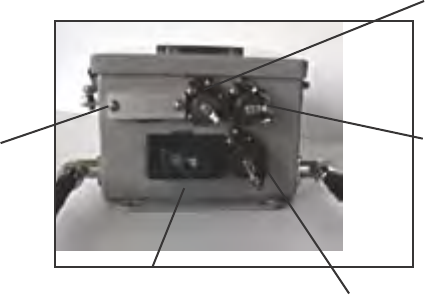
Cabling
The 3e-531AP is well-protected in a metal enclosure which is gen-
erally bolted to the bulkhead. The front of the box is hinged but should
not be opened, particularly if being employed as FIPS 140-2 compatible
device.
The following illustration shows the external cabling on the 3e-531AP.
However, even if the On-off switch is “on”, if the lid of the device is
opened, power will cease to ow because of the safety interlock.
Printer
connector
(Not active in
3e-531APs.)
AC Power
Connector
Power
Switch
(On/Off)
Local
Ethernet
Connector
Ethernet
uplink
An AC Power Connector (not provided) can be plugged into an AC
outlet. In some situations, the installation design may include elimination
of the ability to plug the unit into an AC outlet. In such circumstances, the
AC power is supplied (that is, hardwired) using the same AC Power Con-
nector port. Usually, in the default conguration of the 3e-531AP, the AC
Power Connector is not actively used. The socket outlet must be installed
near the equipment and be easily accessible.
The Ethernet Uplink connector is used to connect the 3e-531AP to the
shipboard LAN. When used as a PoE device, the Ethernet Uplink con-
nector will have been routed from the unit to a PoE-capable hub switch
which runs the power through the Ethernet cable to the unit. The Ethernet

3e-531AP Wireless Access Point Chapter 2: Hardware Installation
12 29000125-001 C
cable is thus run from the 3e-531AP to the PoE-capable hub switch which
is then connected to the wired LAN and to a power source.
The 3e-531AP design includes an external Power Switch for the pur-
pose of disabling power to the unit for servicing or removal.
Although a safety interlock is provided on the unit to disable power
when the enclosure door is opened, AC and PoE power cables must be
disconnected prior to servicing or removing the device. This is a precau-
tionary measure.
An additional Ethernet connector labeled "Local" is designated for use
during initial conguration. The installation team uses an RJ45 cable with
Circular connector to connect the 3e-531AP to a laptop.
Indicator Lights
The top panel of the 3e-531AP contains a set of indicator lights (Light
Emitting Diodes or LEDs) that help describe the state of various network-
ing and connection operations.
This closeup shows the ground and one of the seals that
are standard on the FIPS 140-2 compliant 3e-531AP.
Note that the ground will be installed permanently on
installation of the unit and should not be disturbed after
that.
Power
Ethernet Uplink
Wireless LAN
Activity
Error State
LED indicator
LED Description
Power The Power indicator LED informs you when the
gateway is on or off. If this light is on, the gateway is
on; if it is not on, the gateway is off. During rmware
upgrades and resets, this light will blink
Ethernet Uplink This light indicates the state of your connection to the
shipboard network. When on, the WAN light indicates
that the gateway is connected to the network. When
the WAN light is off, the gateway does not have an ac-
tive connection to the shipboard network.
Wireless LAN Activity This light may be steady or blinking and indicates that
information is passing through the connection.
Error State
LED indicator
The Error State LED indicator will light to alert you if
the device enters Error State. If the 3e-531AP enters an
Error State, you must power down and up (using the
On/Off switch), to allow it to invoke the power-up self
tests.
3e-531AP Wireless Access Point Chapter 3: Access Point Conguration
29000125-001 C 13
Chapter 3: Access Point Conguration
Introduction
The 3e-531AP Gateway comes with the capability to be congured as
either an access point, a gateway, or a bridge.
An “access point” is a device congured to allow one LAN to freely
exchange data with another LAN without restriction. This is useful if
you have an existing network and you want to extend it with a wireless
network. For example, an existing wired LAN is extended by adding the
3e-531AP and thus bridging to the existing wired network resources con-
gured to communicate with the wireless LAN.
The 3e-531AP default conguration is as an access point, allowing free
roaming and data exchange with the existing LAN, bridging the wired
and wireless networks.
In the event that certain areas of the network need greater security,
the Administrator can alternatively, using the management software ac-
cessible through the WEB browser at the device’s assigned IP address,
recongure it as a gateway.
This chapter follows the procedure for conguring the 3e-531AP as
an access point. The procedure for conguring as a gateway is covered in
Chapter 4. Bridging is addressed in Chapter 5.

3e-531AP Wireless Access Point Chapter 3: Access Point Conguration
14 29000125-001 C
3e-531AP Wireless Access Point Chapter 3: Access Point Conguration
29000125-001 C 15
Preliminary Conguration Steps
For preliminary installation the security ofcer (CryptoOfcer) should
have the following information:
• IP address – a list of IP addresses that are assignable to be used for
assignment to the APs
• Subnet Mask for the LAN
• Default IP address of the 3e-531AP
• DNS IP address
• SSID – an ID number/letter string that you want to use in the con-
guration process to identify all members of the wireless LAN.
• The MAC addresses of all the wireless cards that will be used to
access the 3e-531AP network of access points (if MAC address
ltering is to be enabled)
• Security Server IP Address, password, and Key type (if Dynamic
Key Management will be used)
• The appropriate encryption key for Static 3DES or Static AES if
static key management will be used.
Initial Setup using the “Local” Port
Initial setup of the 3e-531AP devices as a wireless LAN is accom-
plished by an installation team. The following information is provided for
the CryptoOfcer for use if an additional 3e-531AP needs to be added to
the conguration.
Plug one end of a separately purchased RJ-45 Crossover Ethernet
cable with one circular connector to the LAN port of the 3e-531AP (see
page 11) and the other end to an Ethernet port on your laptop. This LAN
port in the 3e-531AP connects you to the device’s internal DHCP server
which will dynamically assign an IP address to your laptop so you can
access the device for reconguration. In order to connect properly to the
3e-531AP on the LAN port, you must be sure that the TCP/IP parameters
on your laptop are set to “obtain IP address automatically.” (If you are
unfamiliar with this procedure, use the following instructions for deter-
mining or changing your TCP/IP settings.)
In Windows 95/98 click Start à Settings à Control Panel. Find
and double click the Network icon. In the Network window, high-
light the TCP/IP protocol for your LAN and click the Properties
button. Make sure that the radio button for Obtain an IP address
automatically is checked.
In Windows 2000/XP, follow the path Start à Settings à Net-
work and Dialup Connections à Local Area Connection and select
the Properties button. In the Properties window, highlight the TCP/
IP protocol and click properties. Make sure that the radio button for
Obtain an IP address automatically is checked.

3e-531AP Wireless Access Point Chapter 3: Access Point Conguration
14 29000125-001 C
3e-531AP Wireless Access Point Chapter 3: Access Point Conguration
29000125-001 C 15
Once the DHCP server has recognized your laptop and has assigned a
dynamic IP address, you will need to nd that IP address. Again, the pro-
cedure is similar for Windows 95/98/Me machines and slightly different
for Windows 2000/XP machines.
In Windows 95/98/Me, click Start, then Run and type winipcfg
in the run instruction box. Then click OK. You will see the IP address
of your laptop in the resulting window, along with the “default gate-
way” IP address. Verify that the IP address shown is 192.168.15.x
In Windows 2000, click Start, then Run and type cmd in the run
instruction box. Then click OK. This will bring up a window. In this
window, type ipcong /all |more. This will list information assigned
to your laptop, including the IP address assigned. Verify that the IP
address shown is 192.168.15.x
On your computer, pull up a browser window and put the de-
fault URL for the 3e-531AP Local LAN in the address line. (https://
192.168.15.1)
You will be asked for your User Name and Password. The default for
the CryptoOfcer is "CryptoOfcer" with the password "CryptoFIPS" to
give full access for setup conguration. (This password is case-sensitive.)
3e-531AP Wireless Access Point Chapter 3: Access Point Conguration
16 29000125-001 C
3e-531AP Wireless Access Point Chapter 3: Access Point Conguration
29000125-001 C 17
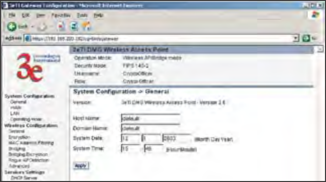
System Conguration
General
You will immediately be directed to the System Conguration—Gen-
eral page for the 3e-531AP access point.
This screen lists the rmware version number for your 3e-531AP and
allows you to set the Host Name and Domain Name as well as establish
system date and time. (Host and Domain Names are both set at the fac-
tory for “default” but can optionally be assigned a unique name for each.)
When you are satised with your changes, click Apply.
Go next to the System Conguration—WAN page.
3e-531AP Wireless Access Point Chapter 3: Access Point Conguration
16 29000125-001 C
3e-531AP Wireless Access Point Chapter 3: Access Point Conguration
29000125-001 C 17
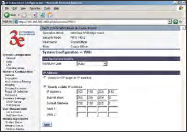
WAN
Next, click the entry on the left hand navigation panel for System
Conguration -WAN. You will be directed to the System Conguration
– WAN page.
This screen allows you to set Link Speed and Duplex of the WAN
port. If you select a choice other than Auto (the default), the 3e-531AP
will use only the selected link speed (10 Mbits/sec or 100 Mbits/sec) and
Duplex (Half Duplex transfers or Full Duplex transfers) that you select in
the WAN/LAN Link dropdown menu.
If not using DHCP to get an IP address, input the information that the
access point requires in order to allow the wireless devices it controls ac-
cess to the wired LAN. This will be the IP address, Subnet Mask, Default
Gateway, and, where needed, DNS 1 and 2.
Click Apply to accept changes.
3e-531AP Wireless Access Point Chapter 3: Access Point Conguration
18 29000125-001 C
3e-531AP Wireless Access Point Chapter 3: Access Point Conguration
29000125-001 C 19
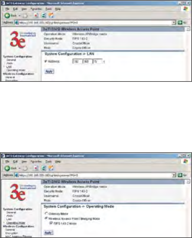
LAN
This sets up the default numbers for the rst, second, or third octet for
a possible private LAN function for the access point. The Local LAN port
provides DHCP server functionality to automatically assign an IP address
to a computer Ethernet port. It is not advisable to change the private
LAN address while doing the initial setup as you are connected to that
LAN.
Operating Mode
You need to visit this page only if you will be changing mode from
Access Point or Bridge to Gateway or vice versa. The default setting is Ac-
cess Point. Note that if you change mode, all previously entered informa-
tion will be reset to factory settings. If in Access Point/ Bridging Mode,
you can also select or deselect the FIPS 140-2 Mode. Selecting FIPS 140-2
Mode makes WEP, SNMP, and 802.1x unavailable as encryption options.
3e-531AP Wireless Access Point Chapter 3: Access Point Conguration
18 29000125-001 C
3e-531AP Wireless Access Point Chapter 3: Access Point Conguration
29000125-001 C 19
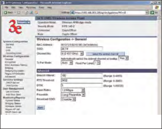
Wireless Setup
General
Wireless Setup allows your comupter's PC card to talk to the Access
Point.
On the Wireless Conguration — General page, you must enter the
SSID for the wireless LAN. This is also where you can assign a channel
number to the AP (if necessary) and modify the Tx Pwr Mode.
The SSID can be any set of letters and numbers assigned by the net-
work administrator. This nomenclature has to be set on the access point
and each wireless device in order for them to communicate.
The Channel Number is a means of assigning frequencies to a series
of access points, when many are used in the same WLAN, to minimize
interference. You can assign channels manually or automatically, using
the Automatically select the optimal channel at bootup function. If as-
signing manually, there are 11 channel numbers that may be assigned. If
you assign channel number 1 to the rst in a series, then channel 6, then
channel 11, and then continue with 1, 6, 11, you will have the optimum
frequency spread to decrease “noise.” If you wish to assign automatically,
set the auto function to YES.
Tx Pwr Mode and Fixed Pwr Level: The Tx Power Mode defaults to
Auto, giving the largest range of radio transmission available under nor-
mal conditions. As an option, the AP's broadcast range can be limited by
setting the Tx Power Mode to Fixed and choosing from 1-8 for Fixed Pwr
Level (1 being the shortest distance.) Finally, if you want to prevent any
radio frequency transmission, set Tx Pwr Mode to Off.
If you have the 3e AP congured in any mode except FIPS, setting TX

3e-531AP Wireless Access Point Chapter 3: Access Point Conguration
20 29000125-001 C
3e-531AP Wireless Access Point Chapter 3: Access Point Conguration
29000125-001 C 21
Pwr Mode to Off will only shut off the power on that one AP.
If you have the 3e AP congured in FIPS mode and you have de-
ployed the 3e-010F Crypto Client software v 2.6 or higher, however, you
can use this management screen to turn off TX power to this particular AP
and all client devices associated with it.
In FIPS Wireless AP mode, once you have given the command to turn
off TX power, The screen called Monitoring/Reports -> Wireless Clients
will contain a column called EMCON which shows the results of the
command on any wireless device associated with the AP. This is more
fully explained in Chapter 7, The RF Manager Function.
The 3e Access Point Installation CD contains the RF Manager Installa-
tion program. If you install this program, which is explained in Chapter 7,
you can control the TX power level and TX power shutoff from a central
location.
If you turn off TX power, whether from the Wireless Conguration
— General page on each AP or using the RF Manager, turning it back on
re-establishes it only in the AP or APs contacted. The wireless devices that
are associated with those APs will need to re-establish power either by
powering down and then powering up or by removing and reinserting
the PC Card.
Use of the RF Manager allows a Crypto Ofcer or Administrator to
manage TX Power level for a group of APs.
In the last section of the Wireless Conguration — General page,
there are a number of advanced options which are described in the fol-
lowing chart:
Beacon interval 0-4095 The frequency in milliseconds in which the
802.11 beacon is transmitted by the AP.
RTS Threshold 0-3000 The number of bytes used for the RTS/CTS
handshake boundary. When a packet size is
greater than the RTS threshold, the RTS/CTS
handshaking is performed.
DTIM 1-65535 The number of beacon intervals between suc-
cessive Delivery Trafc
Identication Maps (DTIMs). This feature is
used for Power Save Mode.
Basic Rates - 1 and 2 Mbps
- 1, 2, 5.5 and 11
Mbps
The basic rates used and reported by the
AP. The highest rate specied is the rate that
the AP uses when transmitting broadcast/
multicast and management frames.
Preamble Short/Long Pre-
amble
Species whether frames are transmitted with
the Short or Long Preamble.
Broadcast SSID Enabled/disabled When disabled, the AP hides the SSID in
outgoing beacon frames and stations cannot
obtain the SSID through passive scanning.
Also, when it is disabled, the AP doesn’t send
probe responses to probe requests with un-
specied SSIDs.
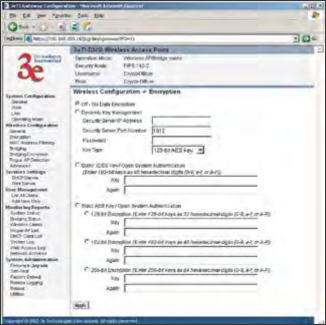
Encryption
The default factory setting for the 3e-531AP is no encryption. It is
3e-531AP Wireless Access Point Chapter 3: Access Point Conguration
20 29000125-001 C
3e-531AP Wireless Access Point Chapter 3: Access Point Conguration
29000125-001 C 21
recommended that you set encryption as soon as possible. If your mode
setting includes FIPS 140-2 mode, WEP encryption is not an option. WEP
will appear as an option in AP mode if not using the ultra-secure FIPS
140.2 encryption settings.
Dynamic Key Management
Dynamic key management requires the installation of the 3e-030 Secu-
rity Server software which resides on a self-contained workstation con-
nected to the 3e-531AP over the Ethernet Uplink WAN port. The Security
Server software conguration includes: obtaining a root certicate from
a Certicate Authority (CA) like Microsoft; obtaining user certicates
based on the CA which will be used by the clients; and conguring the 3e
Technologies International's Security Server software with the appropri-
ate root certicate. The Security Server software application is discussed
in a separate manual.
If you have installed the Security Server software, Dynamic Key
Management is the preferred security setup. Get the IP Address and
password of the Security Server and the Key type. Key type will be either
3DES (192-bit), or AES (128-bit, 192-bit or 256-bit). Thereafter, the Security
Server handles authentication dynamically.
Static 3DES Key/Open System Authentication
If you do not have a Security Server installed, the 3e-531AP can ac-
commodate static encryption using either AES or 3DES.
To use 3DES, enter a 192-bit key as 48 hexidecimal digit (0-9,a-f, or
A-F).
3e-531AP Wireless Access Point Chapter 3: Access Point Conguration
22 29000125-001 C
3e-531AP Wireless Access Point Chapter 3: Access Point Conguration
29000125-001 C 23
Static AES Key/Open System Authentication
The Advanced Encryption Standard (AES) was selected by National
Institute of Standards and Technology (NIST) in October 2000 as an up-
grade from the previous DES standard. AES uses a 128-bit block cipher
algorithm and encryption technique for protecting computerized infor-
mation. With the ability to use even larger 192-bit and 256-bit keys, if
necessary, it offers higher security against brute-force attack than the old
56-bit DES keys.
Once you have selected the options you will use, click Apply.
If you will be using MAC Address ltering, navigate next to the MAC
Address Filtering page.
3e-531AP Wireless Access Point Chapter 3: Access Point Conguration
22 29000125-001 C
3e-531AP Wireless Access Point Chapter 3: Access Point Conguration
29000125-001 C 23
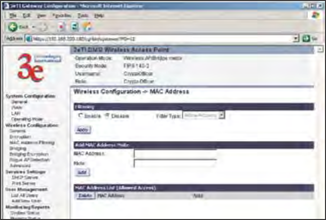
MAC Address Filtering
The factory default for MAC Address ltering is Disabled. If you
enable MAC Address ltering, you should also set the toggle for Filter
Type.
This works as follows:
• If Filtering is enabled and Filter Type is Allow Access, only those
devices equipped with the authorized MAC addresses will be able
to communicate with the access point. In this case, input the MAC
addresses of all the PC cards that will be authorized to access this
access point. The MAC address is engraved or written on the PC
(PCMCIA) Card.
• If Filtering is enabled and Filter Type is Disallow Access, those
devices with a MAC address which has been entered in the MAC
Address listing will NOT be able to communicate with the access
point. In this case, navigate to the report: Wireless Clients and
copy the MAC address of any Wireless Client that you want to ex-
clude from communication with the access point and input those
MAC Addresses to the MAC Address list.
Bridging and Bridging Encryption
Bridging is covered in chapter ve. If you will be deploying this 3e-
531AP as a bridge, follow the instructions in chapter ve.
3e-531AP Wireless Access Point Chapter 3: Access Point Conguration
24 29000125-001 C
3e-531AP Wireless Access Point Chapter 3: Access Point Conguration
29000125-001 C 25
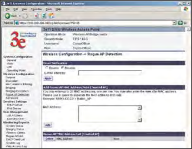
Rogue AP Detection
The Rogue AP Detection page allows the network administrator to set
up rogue AP detection. If you enable rogue AP detection, also enter the
MAC Address of each AP in the network that you want the AP being con-
gured to accept as a trusted AP. (You may add up to 20 APs.) Enter an
email address for notication of any rogue or non-trusted APs. (The MAC
Address for the 3e-531AP is located on the Setup—General page.
The Rogue AP list, under Monitoring Reports on the navigation
menu, will detail any marauding APs.
802.1x
802.1x is not available if you are using the FIPS 140-2 secure setup
mode. 802.1x is a means of making a WEP encrypted system more secure.
Enabling 802.1x requires that you have at least one remote Radius
server (preferably also a backup Radius server) but it will allow the use of
the legacy WEP encrypton key system with greater resultant security.
IEEE 802.1X offers an effective framework for authenticating and con-
trolling user trafc to a protected network, as well as dynamically varying
encryption keys. 802.1X ties a protocol called EAP (Extensible Authentica-
tion Protocol) to both the wired and wireless LAN media and supports
multiple authentication methods, such as token cards, Kerberos, one-time
passwords, certicates, and public key authentication.
If using 802.1x, you must know and input the IP addess, Port Number
and Shared Secret for the primary and backup Radius server and the key
type selected on your Wireless Encryption page. Then set the accepted
lifetime for the encryption key.
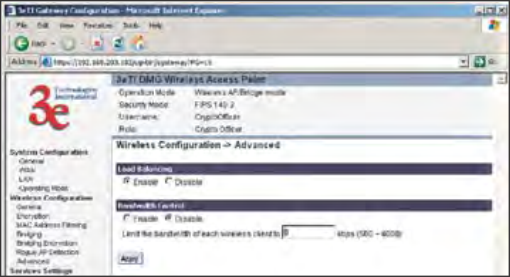
Advanced
The Advanced page allows you to enable or disable load balancing
3e-531AP Wireless Access Point Chapter 3: Access Point Conguration
24 29000125-001 C
3e-531AP Wireless Access Point Chapter 3: Access Point Conguration
29000125-001 C 25
and to control bandwidth.
Load balancing is enabled by default. Load balancing distributes traf-
c efciently among network servers so that no individual server is over-
burdened. For example, the load balancing feature balances the wireless
clients between APs. If two APs with similar settings are in a conference
room, depending on the location of the APs, all wireless clients could po-
tentially associate with the same AP, leaving the other AP unused. Load
balancing attempts to evenly distribute the wireless clients on both APs.
If enabled, the Bandwidth Control function works by limiting the
maximum bandwidth a single client is allowed to have. For example, if
the total BW for the AP/WLAN is 4 Mbps and BW control is set to 500
kbps or 0.5 Mbps, the network can only serve a maximum of 0.5 mbps
per client. Even if only 1 client is on the network, a maximum of 0.5 Mbps
will be allowed that client. If, on the other hand, the BW Control is set
to a higher number (say 3 Mbps), a single client can take up to 3 Mbps
of bandwidth when it requires it while the other clients will share the
remaining bandwidth. The decision as to who gets the 3 Mbps and who
gets the remainder depends on the requirement and when the require-
ment is acknowledged. This function can be disabled, on the other hand,
and the available bandwidth will be portioned out as required. If total
bandwidth required exceeds the available bandwidth, the client last in
line will get only the remaining bandwidth available.
Once you have made any changes, click Apply to save.
3e-531AP Wireless Access Point Chapter 3: Access Point Conguration
26 29000125-001 C
3e-531AP Wireless Access Point Chapter 3: Access Point Conguration
29000125-001 C 27
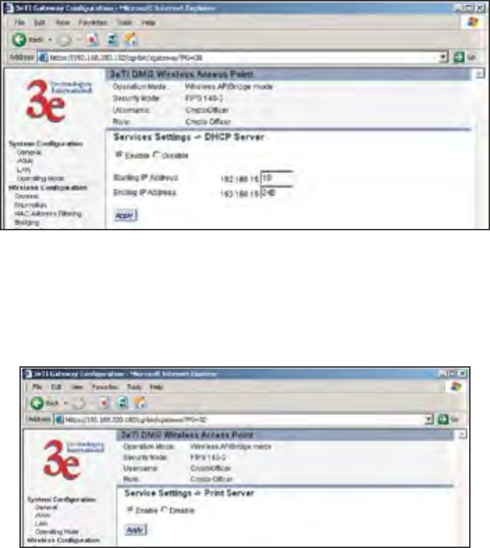
Services Settings
DHCP Server
This page allows conguration of the DHCP server function accessible
from the Local LAN port. The default factory setting for the DHCP server
function is enabled. You can disable the DHCP server function, if you
wish. You can also set the range of addresses to be assigned.
Print Server
The print server function can be enabled or disabled. It is enabled by
default. If you do not plan to set up the print server function, you can
click disable and leave the metal plate on the printer port. The metal plate
is provided to protect that port from water.
3e-531AP Wireless Access Point Chapter 3: Access Point Conguration
26 29000125-001 C
3e-531AP Wireless Access Point Chapter 3: Access Point Conguration
29000125-001 C 27
SNMP
The SNMP (simple network management protocol) Agent is not
available if you are using the FIPS 140-2 setup. SNMP is available in ac-
cess point mode if FIPS 140-2 is left unchecked.
The SNMP Agent setup page allows you to set up an SNMP Agent.
The agent is a software module that collects and stores management
information for use in a network management system. The 3e-531AP's
integrated SNMP agent software module translates the device’s manage-
ment information into a common form for interpretation by the SNMP
Manager, which usually resides on a network administrator’s computer.
The SNMP Manager function interacts with the SNMP Agent to
execute applications to control and manage object variables (interface
features and devices) in the gateway. Common forms of managed infor-
mation include number of packets received on an interface, port status,
dropped packets, and so forth. SNMP is a simple request and response
protocol, allowing the manager to interact with the agent to either
• Get - Allows the manager to Read information about an object
variable
• Set - Allows the manager to Write values for object variables with-
in an agent’s control, or
• Trap - Allows the manager to Capture information and send an
alert about some pre-selected event to a specic destination
The SNMP conguration consists of several elds, which are ex-
plained below:
• Community –The Community eld for Get (Read Only), Set
(Read & Write), and Trap is simply the SNMP terminology for
“password” for those functions.
• Source –The IP address or name where the information is ob-
tained.
• Access Control –Denes the level of management interaction per-
mitted.
3e-531AP Wireless Access Point Chapter 3: Access Point Conguration
28 29000125-001 C
3e-531AP Wireless Access Point Chapter 3: Access Point Conguration
29000125-001 C 29
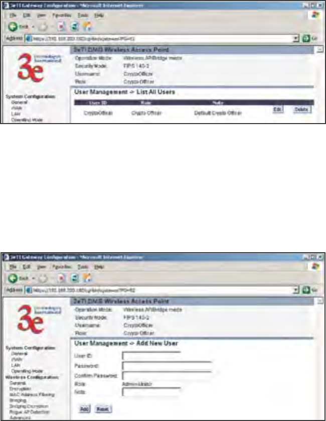
User Management
List All Users
The List All Users page simply lists all Crypto Ofcers and Adminis-
trators assigned.
Add New User
The Add New User screen allows you to add new Administrator us-
ers, assigning and conrming passwords. Only the Crypto Ofcer role is
allowed to add a new Administrator to the 3e-531AP. The Administrator
role performs general security services, including cryptographic opera-
tions and other approved security functions. The Administrator role does
not, however, perform cryptographic initialization or management func-
tions such as module initialization, input or output of cryptographic keys
and CSPs, and audit functions.
3e-531AP Wireless Access Point Chapter 3: Access Point Conguration
28 29000125-001 C
3e-531AP Wireless Access Point Chapter 3: Access Point Conguration
29000125-001 C 29
Monitoring/Reports
This section gives you a variety of lists and status reports. Most of
these are self-explanatory.
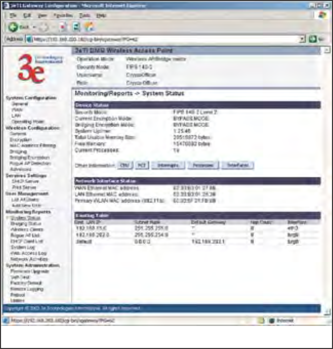
System Status
This screen displays the status of the 3e-531AP device and network
interface details and the Routing Table.
3e-531AP Wireless Access Point Chapter 3: Access Point Conguration
30 29000125-001 C
3e-531AP Wireless Access Point Chapter 3: Access Point Conguration
29000125-001 C 31
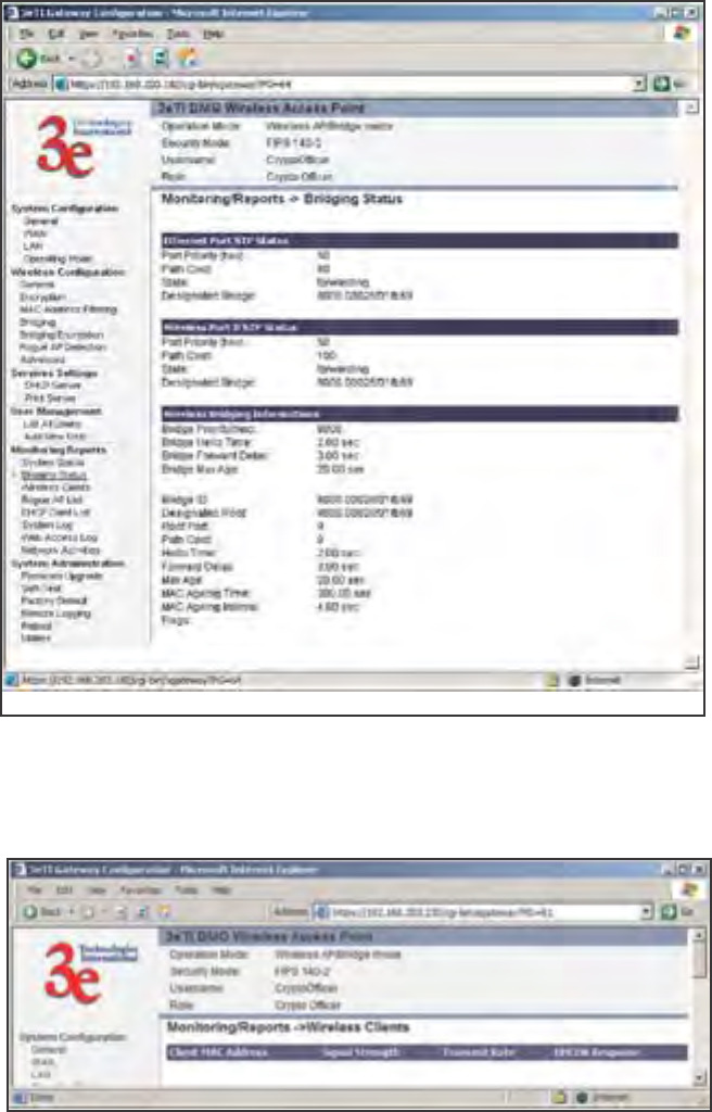
Bridging Status
This screen displays the Ethernet Port STP Status, Wireless Port STP
Status, and Wireless Bridging Information.
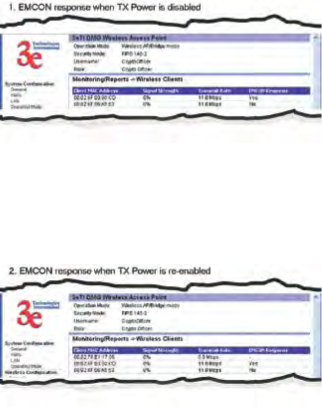
Wireless Clients
The Wireless Clients report screen displays the MAC Address of all
wireless clients and their signal strength and transmit rate.
3e-531AP Wireless Access Point Chapter 3: Access Point Conguration
30 29000125-001 C
3e-531AP Wireless Access Point Chapter 3: Access Point Conguration
29000125-001 C 31
If Transmit power is disabled, either by setting TX Pwr Mode to Off
on the management screen or by using the RF Manager (Chapter 7), the
Wireless Clients page will show the results from each associated client
in the EMCON Response column. If the client responds to the "disable"
command, a Yes is displayed. If the column contains a No, this can mean
either:
• the client didn't receive the command, or
• the client is no longer in the areas, or
• the client software doesn't support the RF management
feature.
This status information remains active for 5 minutes after the clients
are disabled.
Once the transmit power is re-enabled and clients re-associate to the
AP, EMCON information is maintained for them. If a new client that
wasn't associated previously associates with the AP after the EMCON
mode, its EMCON status appears as "-", which indicates the status record
is not applicable.
3e-531AP Wireless Access Point Chapter 3: Access Point Conguration
32 29000125-001 C
3e-531AP Wireless Access Point Chapter 3: Access Point Conguration
29000125-001 C 33
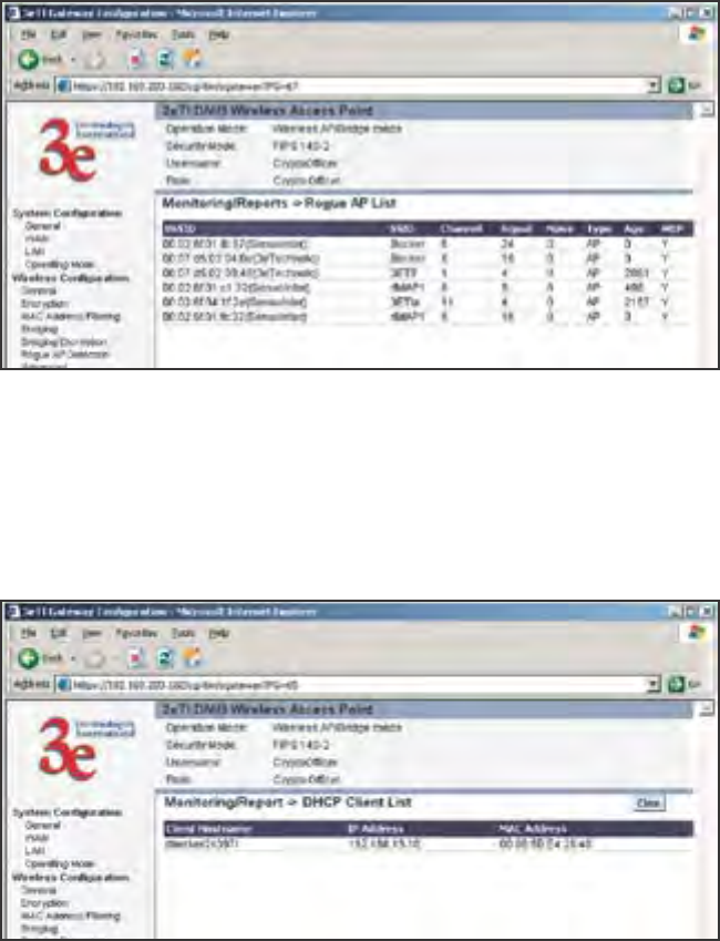
Rogue AP List
The rogue AP list shows all the APs on the network which are not
seen by the subject AP as trusted clients.
DHCP Client List
The DHCP client list displays all clients currently connected to the
3e-531AP via DHCP server, including their hostnames, IP addresses, and
MAC Addresses.
The DHCP client list will continue to accumulate listings unless you
periodically clear it using the Clear button.
3e-531AP Wireless Access Point Chapter 3: Access Point Conguration
32 29000125-001 C
3e-531AP Wireless Access Point Chapter 3: Access Point Conguration
29000125-001 C 33
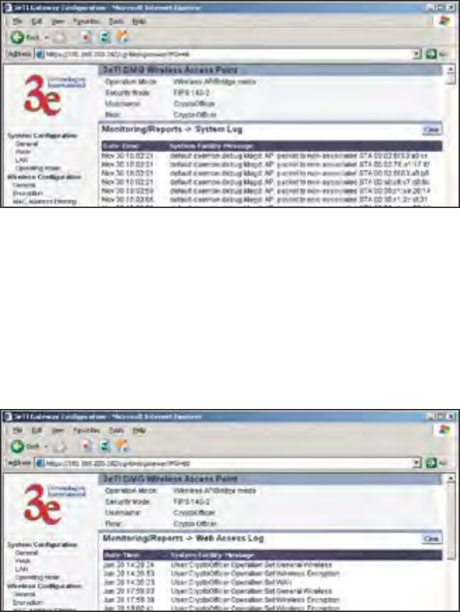
System Log
The system log displays system facility messages with date and time
stamp. These are messages documenting functions performed internal
to the system, based on the system’s functionality. Generally, the Admin-
istrator would only use this information if trained as or working with a
eld engineer or as information provided to technical support.
The System log will continue to accumulate listings unless you peri-
odically clear it using the Clear button.
Web Access Log
The Web access log displays system facility messages with date and
time stamp for any actions involving web access. For example, this log re-
cords when you set encryption mode, change operating mode, etc., using
the web browser. It establishes a running record regarding what actions
were performed and by whom.
The Web access log will continue to accumulate listings unless you
periodically clear it using the Clear button.
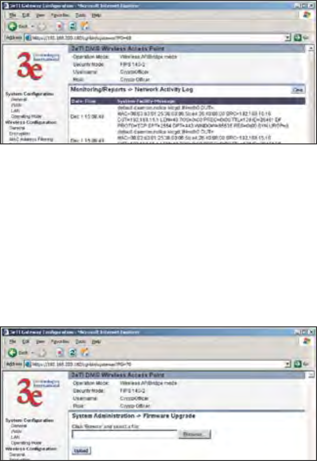
3e-531AP Wireless Access Point Chapter 3: Access Point Conguration
34 29000125-001 C
3e-531AP Wireless Access Point Chapter 3: Access Point Conguration
29000125-001 C 35
Network Activites
The Network Activities Log keeps a detailed log of all activities on the
network which can be useful to the network administration staff.
The Network Activities Log will continue to accumulate listings un-
less you periodically clear it using the Clear button.
System Administration
The System administration screens contain administrative functions,
some of which can only be performed if the user is logged on as a Crypto
Ofcer. The screens and functions are detailed in the following section.
Firmware Upgrade
The System Upgrade utility is a functionality built into the 3e-531AP
for updates to the device’s rmware as they become available. When a
new upgrade le becomes available, nd it and upload it to the 3e-531AP
from this page.
Only the Crypto Ofcer role can access this function.
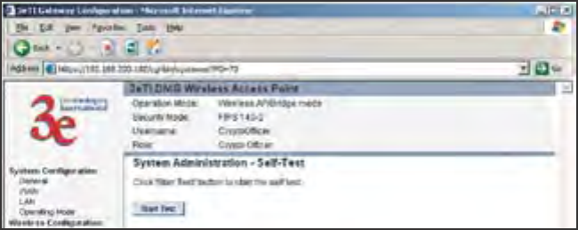
3e-531AP Wireless Access Point Chapter 3: Access Point Conguration
34 29000125-001 C
3e-531AP Wireless Access Point Chapter 3: Access Point Conguration
29000125-001 C 35
Self-Test
Both Crypto Ofcer and Administrator functions can access the
self-test functions. Self-tests are mandated by FIPS 140-2 and should be
employed if you are operating in FIPS 140-2 mode. These include both
power-up tests (such as cryptographic algorithm tests, software/rmware
integrity tests, and critical function tests) and conditional tests. The 3e-
531AP self-test suite includes: AES, 3DES, SHA-1 Algorithms, Random
Number Generation, Dife-Hellman for Dynamic Key Exchange, RSA,
and HMAC SHA1 Algorithm for rmware verication.
If you want to perform a self-test, click on the start test button. A
warning message will appear, stating “If self test fails, the system will
halt. Proceed?” Click OK. If there are no errors, the browser will display
the message: “Self test completed successfully. Hit Back.”
If there are errors, the 3e-531AP will cease functioning. The device will
emit a low-freqency beep for about 1 second. To exit the Error State, you
must power down and power up by disconnecting the power cable (or
POE cable).
The 3e-531AP will then perform normal power up tests. If the Error
State fails to clear, you must replace the device and return it to the manu-
facturer for servicing.
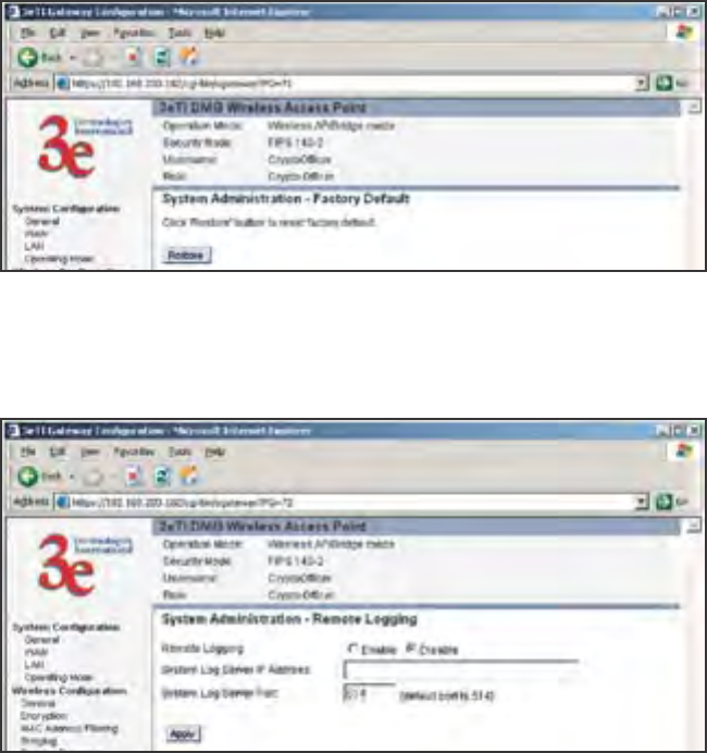
3e-531AP Wireless Access Point Chapter 3: Access Point Conguration
36 29000125-001 C
3e-531AP Wireless Access Point Chapter 3: Access Point Conguration
29000125-001 C 37
Factory Default
The "Restore" button is a fallback troubleshooting function that should
only be used to reset to original settings.
Only the Crypto Ofcer role has access to the Restore button.
Remote Logging
If enabled, input a System Log Server IP Address and System Log
Server Port. Click Apply to accept these values.
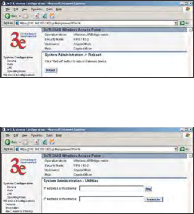
3e-531AP Wireless Access Point Chapter 3: Access Point Conguration
36 29000125-001 C
3e-531AP Wireless Access Point Chapter 3: Access Point Conguration
29000125-001 C 37
Reboot
The Reboot utility allows you to reboot the 3e-531AP without chang-
ing any preset functionality. Both Crypto Ofcer and Administrator func-
tions have access to this function.
Utilities
This screen gives you ready access to two useful utilities: Ping and
Traceroute. Simply enter the IP Address or hostname you wish to ping or
tracerout and click either the Ping or Traceroute button, as appropriate.
3e-531AP Wireless Access Point Chapter 3: Access Point Conguration
38 29000125-001 C
This page intentionally left blank.

3e-531AP Wireless Access Point Chapter 4: Gateway Conguration
29000125-001 C 39
Caution: If you have previously set up your WLAN using
the 3e-531AP devices as access points and you decide to change
the conguration to gateway mode, you will need to convert
the MAC addresses on each wireless device that has been set
up so they can be seen by the recongured system. This is ac-
complished by the following procedure, done on each device
that was congured to use the 3e-531AP when the system was
set up as an access point system. Pull up a System Prompt
(“c:\” prompt, also called an MSDos prompt) on the wireless
device’s desktop. type: arp-d and hit return. This recongures
the MAC address in the wireless device’s PC Card so that it is
now visible to the gateway.
Chapter 4: Gateway Conguration
Introduction
Chapter 3 covered the default conguration of the 3e-531AP Wireless
Access Point as an access point, for use as part of a host wired network.
This chapter covers conguration as a gateway.
If additional security for the wireless network is desired (different-
iating it from the wired network to which it is connected), set it up in
gateway mode. Gateway mode takes advantage of some built-in “router”
functions, such as the gateway’s ability to do Network Address Transla-
tion (NAT), providing private IP addresses for the wireless clients.
A 3e-531AP set up in gateway mode can initiate wireless communic-
ations to the wired network but the wired network can’t initiate commu-
nications to the wireless network unless a specic network address has
been assigned and the user on the wired network knows that address.
The illustration on the following page diagrams the difference.
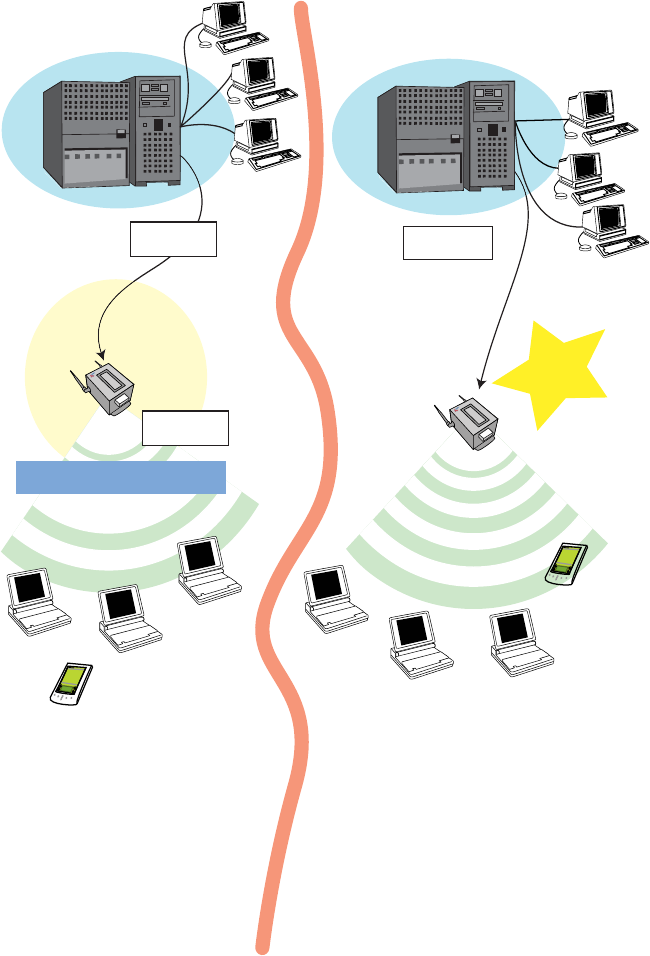
3e-531AP Wireless Access Point Chapter 4 Gateway Conguration
40 29000125-001 C
3e-531AP Wireless Access Point Chapter 4: Gateway Conguration
29000125-001 C 41
A comparison of gateway and access point setup
for the 3e-531AP
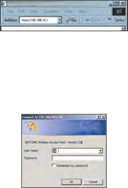
3e-531AP Wireless Access Point Chapter 4 Gateway Conguration
40 29000125-001 C
3e-531AP Wireless Access Point Chapter 4: Gateway Conguration
29000125-001 C 41
Conguring in Gateway Mode
To congure the 3e-531AP in gateway mode, complete the following
steps.
Open a web browser on your monitor (using Netscape Navigator
3.0 or better or Internet Explorer 4.0 or better) and type in the default
IP address of the gateway on its WAN port (for example, https://
192.168.254.254). If you have changed the LAN address of the 3e-531 AP,
then you will need to enter the LAN network address with a station ad-
dress of .1. For example if the LAN address was changed to 10.0.0, then
you would enter “https://10.0.0.1”.
Then click Go on the Web browser.
You will be asked for your User name and password. You will need to
have the ID and password for the Crypto Ofcer role to change the mode
from access point to gateway. If that has not yet been changed, use the
default “CryptoOfcer” with the password “CryptoFIPS” to allow full ac-
cess. Click on OK and you will be directed to the System Conguration
– General page.
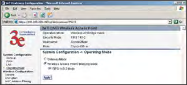
3e-531AP Wireless Access Point Chapter 4 Gateway Conguration
42 29000125-001 C
3e-531AP Wireless Access Point Chapter 4: Gateway Conguration
29000125-001 C 43
Using the navigation bar to the left, navigate to the System Congu-
ration — Operating Mode page, select the Gateway Mode radio button,
and click Apply. The 3e-531AP will reboot in gateway mode and reset all
prior settings to factory default state.
You can then proceed to change the management screens as necessary
to recongure the device as a gateway. Conguration in gateway mode
allows you to set rewall parameters. This is the main difference between
the screens you will see in gateway mode and those covered in access
point setup as discussed in Chapter 3.
Note that you can't deploy the 3e-531AP as a bridge in Gateway
mode, nor is it FIPS 140-2 compliant.
The following sections cover the functions and screens in gateway
mode. Much of the infomation is similar to the access point mode but is
presented here for your convenience.
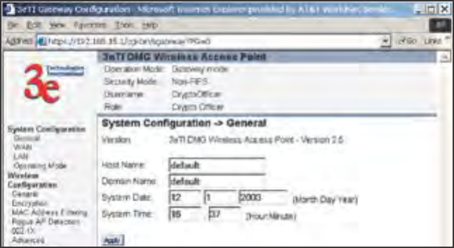
3e-531AP Wireless Access Point Chapter 4 Gateway Conguration
42 29000125-001 C
3e-531AP Wireless Access Point Chapter 4: Gateway Conguration
29000125-001 C 43
System Conguration
General
The System Conguration—General page for the 3e-531AP gateway
lists the rmware Version for your 3e-531AP and allows you to set the
Host Name and Domain Name as well as establish system date and time.
(Host and Domain Names are both set at the factory for “default” but can
optionally be assigned a unique name for each.) When you are satised
with your changes, click Apply.
Go next to the System Conguration—WAN page.
WAN
This screen allows you to set Link Speed and Duplex of the WAN
port. If you select a choice other than Auto (the default), the 3e-531AP
will use only the selected link speed (10 Mbits/sec or 100 Mbits/sec) and
Duplex (Half Duplex transfers or Full Duplex transfers) that you select in
the WAN/LAN Link dropdown menu.
You also set information for how the IP address will be obtained.
The WAN IP address is the Public IP address required to link the pri-
vate WLAN users to the external enterprise or shipboard network, which
is to be outside the “protected” wireless LAN. Normally, you will be
provided with the IP address, Subnet Mask, Default Gateway and DNS
to assign by the Network Administrator for the Ethernet Network.
There are two ways to congure the WAN IP address:
Obtain an IP address Automatically – This conguration allows the
Ethernet network to use the DHCP server on the wired network to dy-
namically assign the WAN IP address to the DHCP client in the gateway.
Specify an IP address – This conguration allows the user to manu-
ally type in a static IP address, default gateway, and Domain Name Server
(DNS) if these are provided by the Ethernet network administrator.
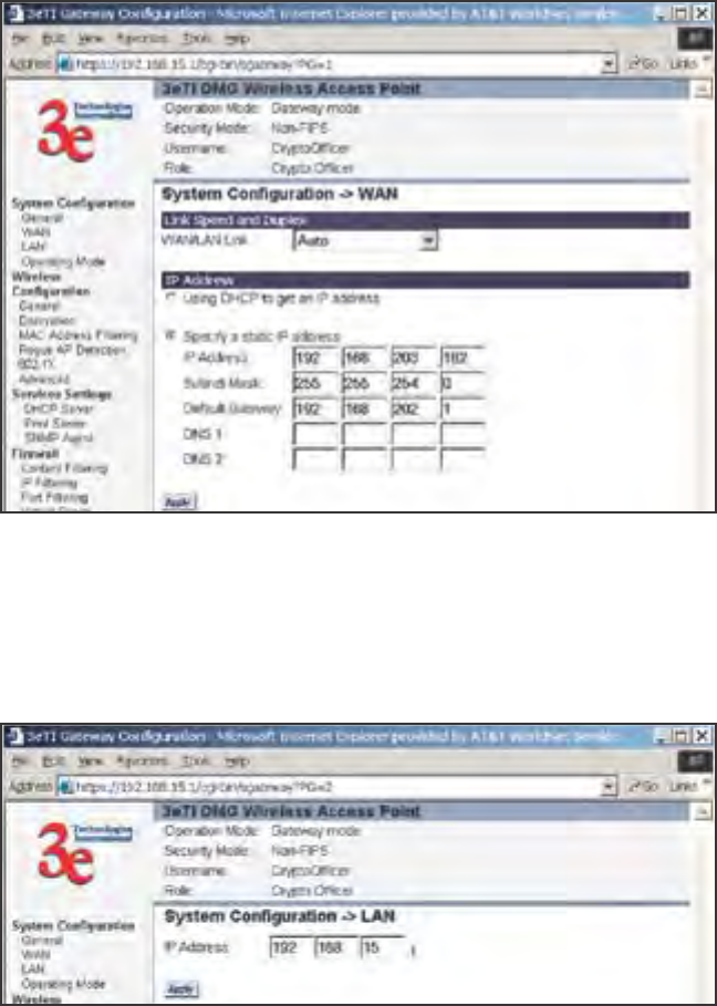
3e-531AP Wireless Access Point Chapter 4 Gateway Conguration
44 29000125-001 C
3e-531AP Wireless Access Point Chapter 4: Gateway Conguration
29000125-001 C 45
LAN
This sets up the default numbers for the rst, second or third octet for
a possible private LAN function for the access point. The Local LAN port
provides DHCP server functionality to automatically assign an IP address
to a computer Ethernet port.
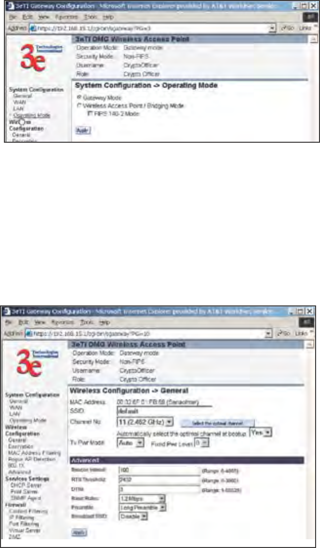
3e-531AP Wireless Access Point Chapter 4 Gateway Conguration
44 29000125-001 C
3e-531AP Wireless Access Point Chapter 4: Gateway Conguration
29000125-001 C 45
Operating Mode
This is the page you accessed to change mode. You need to visit this
page only if you will be changing mode from Gateway to Access Point or
Bridge. Note that if you change mode, all previously entered information
will be reset to factory settings.
Wireless Conguration
General
Wireless conguration allows your computer’s wireless PC Card to
talk to the access point. Once you have completed wireless conguration
of the 3e-531AP, you can set up the rest of the conguration wirelessly
if you wish. (This assumes that you have installed and congured the
secure wireless card on your computer. If you have not done so, you will
have to do that to establish communications.)
On the Wireless Conguration — General page, you must enter the
SSID for the wireless LAN. This is also where you can assign a channel

3e-531AP Wireless Access Point Chapter 4 Gateway Conguration
46 29000125-001 C
3e-531AP Wireless Access Point Chapter 4: Gateway Conguration
29000125-001 C 47
number to the AP (if necessary) and modify the Tx Pwr Mode. There are
some advanced options which are detailed in the chart below.
The SSID can be any set of letters and numbers assigned by the net-
work administrator. This nomenclature has to be set on the gateway and
each wireless device in order for them to communicate.
The Channel Number is a means of assigning frequencies to access
points, when many are used in the same WLAN, to minimize interfer-
ence. There are 11 channel numbers that may be assigned.
Tx Pwr Mode and Fixed Pwr Level: The Tx Power Mode defaults
to Auto, giving the largest range of radio transmission available under
ambient conditions. As an option, the AP’s broadcast range can be limited
by setting the Tx Power Mode to Fixed and choosing from 1-8 for Fixed
Pwr Level (1 being the shortest distance.) Finally, if you want to prevent
any radio frequency transmission from the gateway, set Tx Pwr Mode to
Off. This will not turn off RF transmission from any associated wireless
devices, but they will not be able to communicate with the Gateway when
the TX power mode is off.
Advanced Options:
The advanced options included on the second section of this page are
described in the chart on the following page:
Beacon interval 0-4095 The frequency in milliseconds in which the
802.11 beacon is transmitted by the AP.
RTS Threshold 0-3000 The number of bytes used for the RTS/CTS
handshake boundary. When a packet size
is greater than the RTS threshold, the RTS/
CTS handshaking is performed.
DTIM 1-65535 The number of beacon intervals between
successive Delivery Trafc
Identication Maps (DTIMs). This feature
is used for Power Save Mode.
Basic Rates - 1 and 2 Mbps
- 1, 2, 5.5 and 11
Mbps
The basic rates used and reported by
the AP. The highest rate specied is the
rate that the AP uses when transmitting
broadcast/multicast and management
frames.
Preamble Short/Long Pre-
amble
Species whether frames are transmitted
with the Short or Long Preamble
Broadcast SSID Enabled/disabled When disabled, the AP hides the SSID
in outgoing beacon frames and stations
cannot obtain the SSID through passive
scanning.
Also, when it is disabled, the AP doesn’t
send probe responses to probe requests
with unspecied SSIDs.
Encryption
3e-531AP Wireless Access Point Chapter 4 Gateway Conguration
46 29000125-001 C
3e-531AP Wireless Access Point Chapter 4: Gateway Conguration
29000125-001 C 47
The default factory setting for the 3e-531AP is no encryption. It is rec-
ommended that you set encryption as soon as possible.
WEP (RC4) Data Encryption
Using the 3e-531AP in gateway mode allows you to employ s the
WEP (RC4) encryption standard if you wish. WEP is not available in AP
or Bridge mode for security reasons.
If using WEP, authentication type can be set to either Open System or
Shared Key. Open System is probably adequate if you are using a remote
authentication server (e.g. RADIUS) with 802.1x.
WEP is designed to provide the same level of security for wireless
LANs as that of a wired LAN. To use WEP encryption, identify the level
of encryption (64 or 128). If using 64-bit WEP, you will need to program
the Default WEP key on the AP and each wireless device and designate
the four alternate 64-bit WEP keys. The four WEP keys thus programmed
have to be input to the setup utility on each wireless device that will be
part of the WLAN.
If using 128-bit WEP, simply designate the 48 hexidecimal digits on
the AP and program the same number on each wireless device.
Key management becomes increasingly difcult as the number of
clients increases, but the use of WEP encryption on small ofce or home
wireless networks provides some measure of security. WEP was never
intended to be a complete security solution but rather provides protection
equivalent to that of wired networks.
Static 3DES Key/Open System Authentication
The 3e-531AP in gateway mode can accommodate advanced static
encryption using either AES or 3DES.
3DES is modeled on the older DES standard but encrypts data three
times over.
To use 3DES, enter a 192-bit key as 48 hexidecimal digit (0-9, a-f, or A-
F). Enter the key twice for verication.
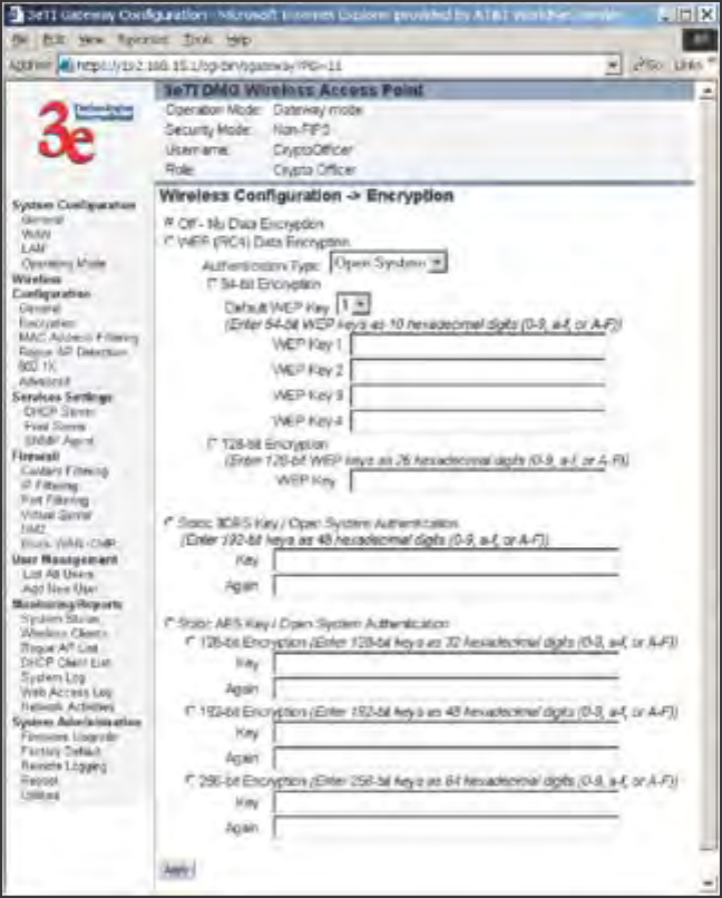
3e-531AP Wireless Access Point Chapter 4 Gateway Conguration
48 29000125-001 C
3e-531AP Wireless Access Point Chapter 4: Gateway Conguration
29000125-001 C 49
Static AES Key/Open System Authentication
The Advanced Encryption Standard (AES) was selected by National
Institute of Standards and Technology (NIST) in October 2000 as an up-
grade from the previous DES standard. AES uses a 128-bit block cipher
algorithm and encryption technique for protecting computerized infor-
mation. With the ability to use even larger 192-bit and 256-bit keys, if
necessary, it offers higher security against brute-force attack than the old
56-bit DES keys. For even greater security, you can select a 192-bit or 256-
bit key.
Once you have selected the options you will use, click Apply.
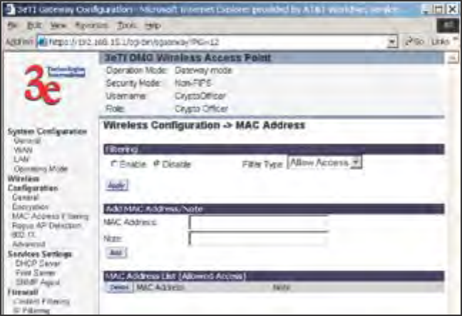
3e-531AP Wireless Access Point Chapter 4 Gateway Conguration
48 29000125-001 C
3e-531AP Wireless Access Point Chapter 4: Gateway Conguration
29000125-001 C 49
Mac Address Filtering
The factory default for MAC Address ltering is Disabled. If you en-
able MAC Address ltering, only those devices equipped with the autho-
rized MAC addresses will be able to communicate with the access point.
Input the MAC addresses of all the PC cards that will be authorized
to access this device. The MAC address is engraved or written on the PC
(PCMCIA) Card. The MAC Addresses you have input and any identify-
ing note will appear in the lower window once you click the Add button.
You delete MAC Addresses by simply clicking the Delete button next to
the MAC Address you no longer want to include in the WLAN.
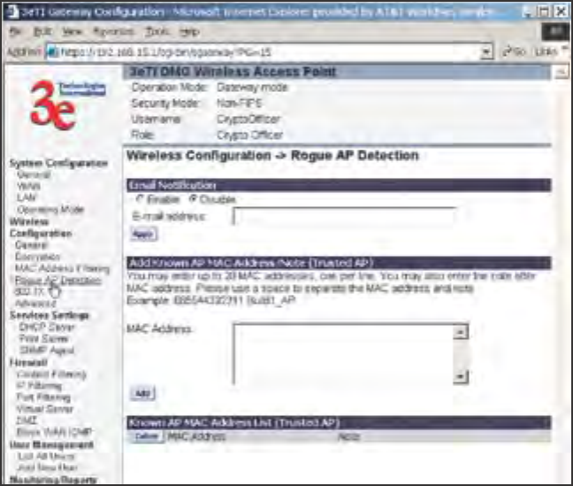
3e-531AP Wireless Access Point Chapter 4 Gateway Conguration
50 29000125-001 C
3e-531AP Wireless Access Point Chapter 4: Gateway Conguration
29000125-001 C 51
Rogue AP Detection
The Rogue AP Detection page allows the network administrator to
set up rogue AP detection. If you enable rogue AP detection, also enter
the MAC Address of each AP in the network that you want the AP being
congured to accept as a trusted AP. (You may add up to 20 APs.) Enter
an email address for notication of any rogue or non-trusted APs.
The Rogue AP list, under Monitoring Reports on the navigation
menu, will detail any marauding APs.
802.1x
Enabling 802.1x requires that you have at least one remote Radius
server (preferably also a backup Radius server) but it will allow the use of
the legacy WEP encrypton key system with greater resultant security.
IEEE 802.1X offers an effective framework for authenticating and con-
trolling user trafc to a protected network, as well as dynamically varying
encryption keys. 802.1X ties a protocol called EAP (Extensible Authentica-
tion Protocol) to both the wired and wireless LAN media and supports
multiple authentication methods, such as token cards, Kerberos, one-time
passwords, certicates, and public key authentication.
If using 802.1x, you must know and input the IP addess, Port Number
and Shared Secret for the primary and backup Radius server and the key
type selected on your Wireless Encryption page. Then set the accepted
lifetime for the encryption key.
This is shown on the next page.
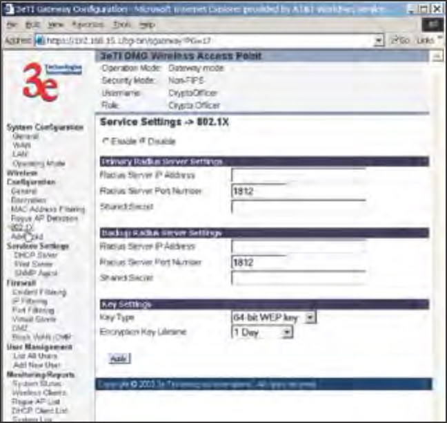
3e-531AP Wireless Access Point Chapter 4 Gateway Conguration
50 29000125-001 C
3e-531AP Wireless Access Point Chapter 4: Gateway Conguration
29000125-001 C 51
Advanced
The Advanced page allows you to enable or disable load balancing
and to control bandwidth.
Load balancing is enabled by default. Load balancing distributes traf-
c efciently among network servers so that no individual server is over-
burdened. For example, the load balancing feature balances the wireless
clients between APs. If two APs with similar settings are in a conference
room, depending on the location of the APs, all wireless clients could po-
tentially associate with the same AP, leaving the other AP unused. Load
balancing attempts to evenly distribute the wireless clients on both APs.
If enabled, the Bandwidth Control function species the maximum
bandwidth given to each wireless client.
Once you have made any changes, click Apply to save.
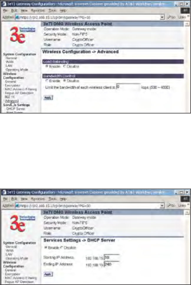
3e-531AP Wireless Access Point Chapter 4 Gateway Conguration
52 29000125-001 C
3e-531AP Wireless Access Point Chapter 4: Gateway Conguration
29000125-001 C 53
Services Settings
DHCP Server
This page allows conguration of the DHCP server function accessible
from the LAN port. The default factory setting for the DHCP server func-
tion is enabled. You can disable the DHCP server function, if you wish.
You can also set the range of addresses to be assigned.
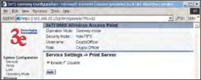
3e-531AP Wireless Access Point Chapter 4 Gateway Conguration
52 29000125-001 C
3e-531AP Wireless Access Point Chapter 4: Gateway Conguration
29000125-001 C 53
Print Server
The print server function can be enabled or disabled. It is enabled by
default. If you do not plan to set up the print server function, you can
click Disable and leave the metal plate on the printer port. The metal
plate is provided to protect that port from water.
SNMP Agent
The SNMP (simple network management protocol) Agent setup page
allows you to set up an SNMP Agent. The agent is a software module
that collects and stores management information for use in a network
management system. The 3e-531AP's integrated SNMP agent software
module translates the device’s management information into a common
form for interpretation by the SNMP Manager, which usually resides on a
network administrator’s computer.
The SNMP Manager function interacts with the SNMP Agent to
execute applications to control and manage object variables (interface
features and devices) in the gateway. Common forms of managed infor-
mation include number of packets received on an interface, port status,
dropped packets, and so forth. SNMP is a simple request and response
protocol, allowing the manager to interact with the agent to either
• Get - Allows the manager to Read information about an object
variable
• Set - Allows the manager to Write values for object variables with-
in an agent’s control, or
• Trap - Allows the manager to Capture information and send an
alert about some pre-selected event to a specic destination
The SNMP conguration consists of several elds, which are ex-
plained below:
• Community –The Community eld for Get (Read Only), Set
(Read & Write), and Trap is simply the SNMP terminology for
“password” for those functions.
• Source –The IP address or name where the information is ob-
tained.
• Access Control –Denes the level of management interaction per-
mitted.
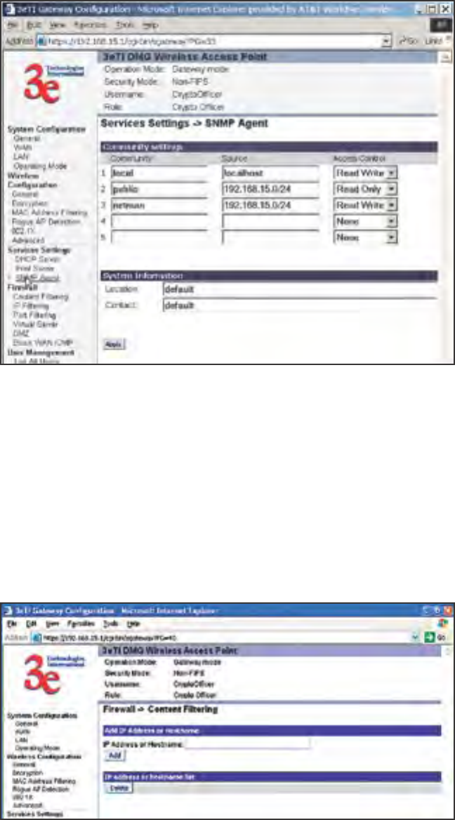
3e-531AP Wireless Access Point Chapter 4 Gateway Conguration
54 29000125-001 C
3e-531AP Wireless Access Point Chapter 4: Gateway Conguration
29000125-001 C 55
Firewall
Content Filtering
The Content Filtering page allows the system administrator to iden-
tify particular hosts or IPs that will be blocked from access by the gate-
way. Simply input the IP address and click Add. Be aware, however, that
the Content Filtering function does not exclude multihomed websites.
Multihomed websites are those having two or more associated network
addresses.
IP Filtering
The IP Filtering page will block certain IPs on the Private LAN from
accessing your Internet connection. It restricts clients to those with a spe-
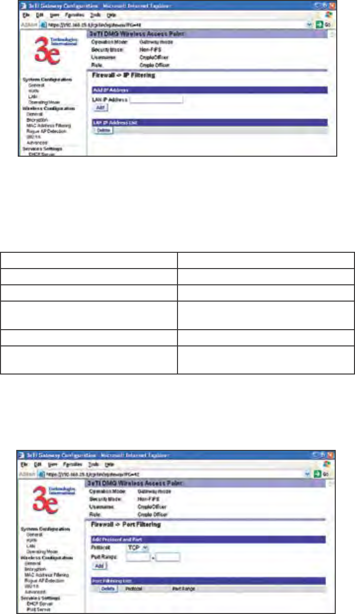
3e-531AP Wireless Access Point Chapter 4 Gateway Conguration
54 29000125-001 C
3e-531AP Wireless Access Point Chapter 4: Gateway Conguration
29000125-001 C 55
cic IP Address.
Port Filtering
Port ltering permits you to congure the Gateway to block outbound
trafc on specic ports. It can be used to block the wireless network from
using specic protocols on the network.
Following is a list of well known TCP and UDP ports.
Port Range Protocol
20-21 FTP
23 Telnet
25 SMTP (Simple Mail Transfer
for email sending)
80 HTTP (World Wide Web)
110 POP3 (Post Ofce Protocol for
email receiving.)
Virtual Server
In order to protect the Private Network, the built-in NAT rewall
lters out trafc to the private network. Since all clients on the Private
Network are normally not visible to outside users, the virtual server func-
tion allows some clients on the Private Network to be accessed by outside
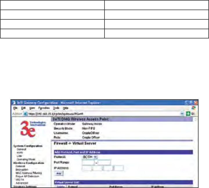
3e-531AP Wireless Access Point Chapter 4 Gateway Conguration
56 29000125-001 C
3e-531AP Wireless Access Point Chapter 4: Gateway Conguration
29000125-001 C 57
users by conguring the application mapping function offered on this
page. Certain well known applications use specic TCP ports, such as
Telnet (port 23), FTP (port 21), and Web server (port 80). Client computers
on the Private LAN can host these applications, and allow users from the
Internet to access these applications hosted on the virtual servers.
This is done by mapping virtual servers to private IP addresses,
according to the specic TCP port application. As the planning table
below shows, we have identied a Telnet (port 23) virtual server for
private IP 192.168.15.56, a SMTP Mail (port 25) virtual server for pri-
vate IP 192.168.15.33, and a Web (port 80) virtual server for private IP
192.168.15.64. For example, all Internet requests to the gateway for SMTP
Mail services (port 25) to the WAN IP address will redirected to the Pri-
vate Network computer specied by the server IP 192.168.15.33.
Service Port Server IP
23 192.168.15.56
25 192.168.15.33
80 192.168.15.64
We recommend that IP addresses of virtual server computers hosted
on the Private Network be manually (statically) assigned to coincide with
a static server mapping to that specic IP address. Virtual servers should
not rely on the dynamic IP assignment of the DHCP server function
which could create unmapped IP address assignments.
Protocol – Selection of either UDP, TCP, or Both (TCP and UDP) al-
lows these specied network protocols to pass through during the TCP
port communication with each virtual server IP address.
Demilitarized Zone (DMZ)
The Demilitarized Zone (DMZ) host allows one computer on the
Private Network to be totally exposed to the wired network or Internet
for unrestricted two-way communication. This conguration is typically
used when a computer is operating a proprietary client software or 2-way
communication such as video-teleconferencing, where multiple TCP port
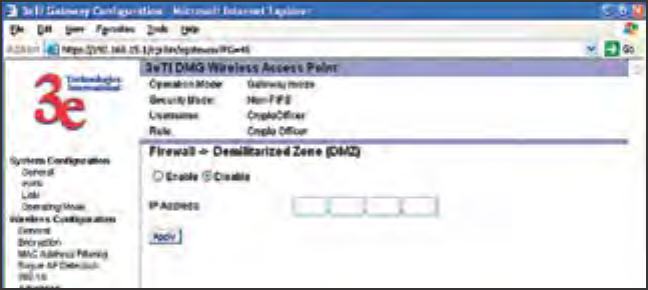
3e-531AP Wireless Access Point Chapter 4 Gateway Conguration
56 29000125-001 C
3e-531AP Wireless Access Point Chapter 4: Gateway Conguration
29000125-001 C 57
assignments are required for communication. To assign a PC the DMZ
host status, ll in the Private IP address which is identied as the exposed
host and click the Apply button. However, any Internet user who knows
the WAN IP address of the gateway can connect to the DMZ host since
the rewall feature is disabled for this device, causing a potential security
risk to data residing on that host.
Again, it is recommended that IP addresses of DMZ host computers
on the Private Network be manually (statically) assigned to coincide with
a static DMZ host mapping to that specic IP address. DMZ hosts should
not rely on the dynamic IP assignment of DHCP server function which
could create incorrectly mapped IP address assignments to non-DMZ
hosts.
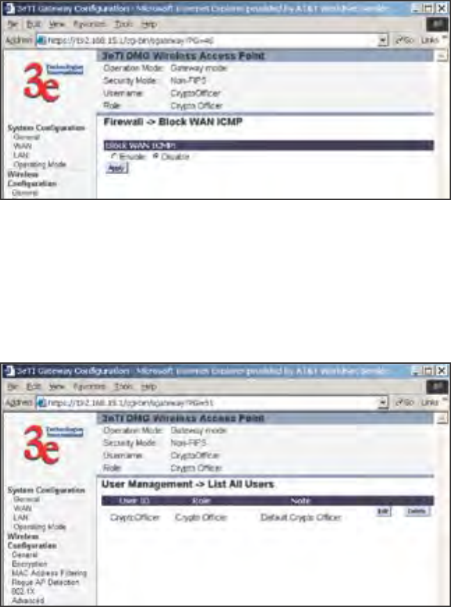
3e-531AP Wireless Access Point Chapter 4 Gateway Conguration
58 29000125-001 C
3e-531AP Wireless Access Point Chapter 4: Gateway Conguration
29000125-001 C 59
Block WAN ICMP
If you enable ICMP (Internet Control Message Protocol) Blocking, a
device outside the WLAN will not get a response to a ping or traceroute
request. The default is disabled which will allow response to ping or
traceroute for connectivity testing.
User Management
List All Users
This List All User page simply lists all Crypto Ofcers and Adminis-
trators assigned.
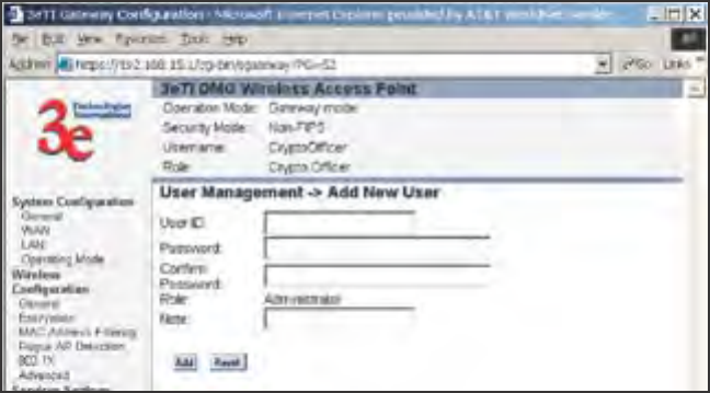
3e-531AP Wireless Access Point Chapter 4 Gateway Conguration
58 29000125-001 C
3e-531AP Wireless Access Point Chapter 4: Gateway Conguration
29000125-001 C 59
Add New User
The Add New User screen allows the Crypto Ofcer to add new
Administrator users, assigning and conrming passwords. The Admin-
istrator role performs general security services, including cryptographic
operations and other approved security functions. The Administrator role
does not, however, perform cryptographic initialization or management
functions such as module initialization, input or output of cryptographic
keys and CSPs, and audit functions.
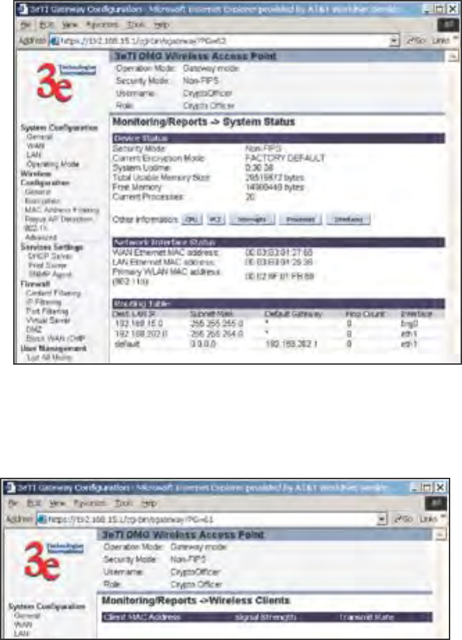
3e-531AP Wireless Access Point Chapter 4 Gateway Conguration
60 29000125-001 C
3e-531AP Wireless Access Point Chapter 4: Gateway Conguration
29000125-001 C 61
Monitoring/Reports
This section gives you a variety of lists and status reports. Most of
these are self-explanatory.
System Status
This screen displays the status of the 3e-531AP device and network
interface details.
Wireless Clients
The Wireless Clients report screen displays the MAC Address of all
wireless clients and their signal strength and transmit rate.
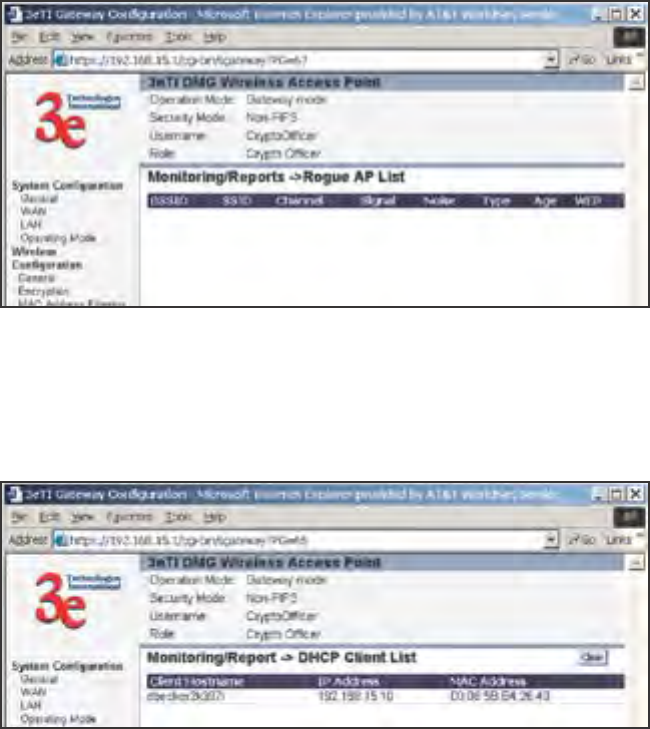
3e-531AP Wireless Access Point Chapter 4 Gateway Conguration
60 29000125-001 C
3e-531AP Wireless Access Point Chapter 4: Gateway Conguration
29000125-001 C 61
Rogue AP List
The rogue AP list shows all the APs on the network which are not
seen by the subject AP as trusted clients.
DHCP Client List
The DHCP client list displays all clients currently connected to the
3e-531AP via DHCP server, including their hostnames, IP addresses, and
MAC Addresses.
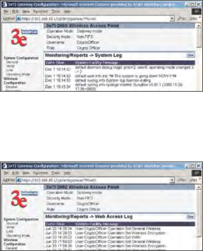
3e-531AP Wireless Access Point Chapter 4 Gateway Conguration
62 29000125-001 C
3e-531AP Wireless Access Point Chapter 4: Gateway Conguration
29000125-001 C 63
System Log
The system log displays system facility messages with date and time
stamp. These are messages documenting functions performed internal
to the system, based on the system’s functionality. Generally, the Admin-
istrator would only use this information if trained as or working with a
eld engineer or as information provided to technical support.
Web Access Log
The web access log displays system facility messages with date and
time stamp for any actions involving web access. For example, this log re-
cords when you set encryption mode, change operating mode, etc., using
the web browser. It establishes a running record regarding what actions
were performed and by whom.
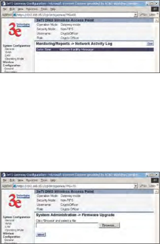
3e-531AP Wireless Access Point Chapter 4 Gateway Conguration
62 29000125-001 C
3e-531AP Wireless Access Point Chapter 4: Gateway Conguration
29000125-001 C 63
Network Activites
The Network Activities Log keeps a detailed log of all activities on the
network which can be useful to the network administration staff.
System Administration
The System administration functions contain administrative func-
tions, some of which can be performed only if the user is logged on as a
Crypto Ofcer. The screens and functions are detailed in the following
section.
Firmware Upgrade
The System Upgrade utility is a functionality built into the 3e-531AP
Series for updates to the device’s rmware as they become available.
When a new upgrade le becomes available, nd it and upload it to the
3e-531AP from this page.
Only the Crypto Ofcer role can access this function.
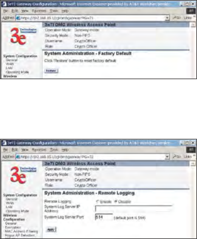
3e-531AP Wireless Access Point Chapter 4 Gateway Conguration
64 29000125-001 C
3e-531AP Wireless Access Point Chapter 4: Gateway Conguration
29000125-001 C 65
Factory Default
The Factory Default or "Restore" button is a fallback troubleshooting
function that should only be used to reset to original settings.
Only the Crypto Ofcer role has access to the Restore button.
Remote Logging
If enabled, input a System Log Server IP Address and System Log
Server Port. Click Apply to accept these values.
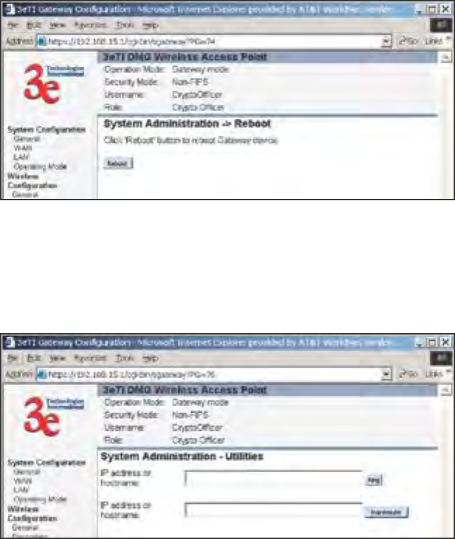
3e-531AP Wireless Access Point Chapter 4 Gateway Conguration
64 29000125-001 C
3e-531AP Wireless Access Point Chapter 4: Gateway Conguration
29000125-001 C 65
Reboot
The Reboot utility allows you to reboot the Gateway without chang-
ing any preset functionality. Both Crypto Ofcer and Administrator func-
tions have access to this function.
Utilities
This screen gives you ready access to two useful utilities: Ping and
Traceroute. Simply enter the IP Address or hostname you wish to ping or
traceroute and click either the Ping or Traceroute button, as appropriate.
3e-531AP Wireless Access Point Chapter 4 Gateway Conguration
66 29000125-001 C
This page intentionally left blank.
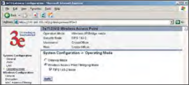
3e-531AP Wireless Access Point Chapter 5: Bridge Conguration
29000125-001 C 67
Chapter 5: Bridge Conguration
Introduction
The wireless bridging function in the 3e-531AP allows setup as a
bridge, in a number of alternate congurations. We discuss some of the
most popular settings in this chapter:
1. Point-to-point bridging of 2 Ethernet Links;
2. Point-to-multipoint bridging of several Ethernet links;
3. Back-to-back bridging mode (with point-to-point bridging) to de-
liver mobile wireless connectivity; and
4. Repeater mode
Preliminary Setup
Your 3e-531AP Wireless Access Point must congured in access point
mode to utilize it as a bridge. If not already in Access Point mode, open
the management module and navigate to the System Conguration
— Operating Mode screen.
Select the radio button for Wireless Access Point/Bridging Mode and
click Apply. If you wish to use Advanced Encryption, check the FIPS 140-
2 Mode option. The unit will reboot. You do not need to log back on. After
reboot, an instructional page will appear and you can then navigate back
to the Management Module main screen.
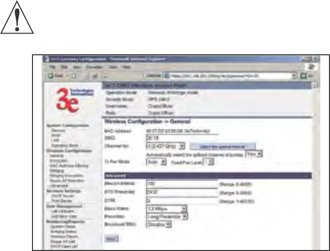
3e-531AP Wireless Access Point Chapter 5: Bridge Conguration
68 29000125-001 C
3e-531AP Wireless Access Point Chapter 5: Bridge Conguration
29000125-001 C 69
General Bridge Setup
Once the unit is in access point mode, the navigation bar on the left
side of the management module will include some screens that relate
specically to bridging. The screens that you may need to modify, regard-
less of what type of bridging mode you choose, will be in the Wireless
Conguration section. These include:
• Wireless Conguration — General
• Wireless Conguration — Encryption
• Wireless Conguration — MAC Address Filtering
• Wireless Conguration — Bridging
• Wireless Conguration — Bridging Encryption.
The Wireless Conguration — Encryption and the Wireless Congu-
ration — MAC Address Filtering are only needed if you are going to set
up the bridge as a repeater. However, we have included a picture of them
in this section for reference purposes.
The Wireless Conguration — General screen is used to set the
SSID and Channel Number and is also the location where you can nd
the device MAC Address, which you will need. If you are setting up the
3e-531AP as a Bridge, the SSID can remain in its default setting, since the
bridge uses the BSSID for purposes of establishing contact. The BSSID
is the MAC Address, which is shown on this page. It is a good idea to
write down the MAC Address before leaving the page. Channel number
is a means of assigning frequencies to access points used in proximity or
series to minimize interference or "noise." There are 11 channel numbers
that can be assigned. Generally, channels 1, 6, and 11 are the best from
which to choose, since these are the channels with optimum frequency
spread. TX Pwr Mode can be left in its default of Auto. If you nd later
that the broadcast range can be decreased, this is where you will set it.
IMPORTANT NOTE: It is vital that you not use the function,
Automatically select the optimal channel at bootup, when you
are conguring the 3e AP as a Bridge. Set the function to NO. In
bridging mode, all APs must be on the same RF Channel.
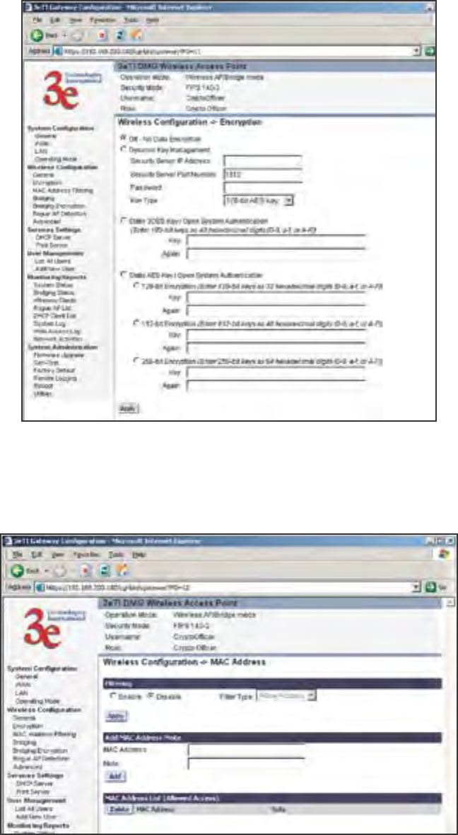
3e-531AP Wireless Access Point Chapter 5: Bridge Conguration
68 29000125-001 C
3e-531AP Wireless Access Point Chapter 5: Bridge Conguration
29000125-001 C 69
The Wireless Conguration — Encryption screen sets the encryption
type and level for the WLAN. This page is only needed for repeater setup.
The Wireless Conguration — MAC Address Filtering screen would
be used if the wireless LAN is using MAC Filtering. This page is only
needed for repeater setup.
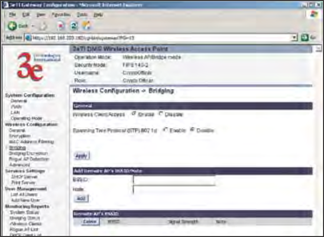
3e-531AP Wireless Access Point Chapter 5: Bridge Conguration
70 29000125-001 C
3e-531AP Wireless Access Point Chapter 5: Bridge Conguration
29000125-001 C 71
The Wireless Conguration — Bridging screen is used to enable/
disable Wireless Client Access and Spanning Tree Protocol and to con-
gure the BSSID of the peer bridges. This page is important in setting
up your bridge conguration. We recommend that you disable Wireless
Client Access for all bridge setups except repeater. Spanning Tree Protocol
should be enabled if there is any possibility that a bridging loop could oc-
cur. If you are certain that there is no possibility that a bridging loop will
occur, you should disable Spanning Tree Protocol, because the bridge will
be more efcient (faster) without it. However, if not sure, the safest solu-
tion is to enable Spanning Tree Protocol.
The Wireless Conguration — Bridging Encryption page is used to
congure static encryption keys for the wireless bridge. This is an impor-
tant page to set up to ensure that your bridge is working correctly. The en-
cryption key that you use on this screen must be the same for any bridge
connected to your bridging network in order for communication to occur.
And on this screen, you can only select either a static 192 bit 3DES key or
an AES key of either 128-bit, 192-bit, or 256-bit.
NOTE: You can also select to leave encryption OFF, but this is not
recommended.
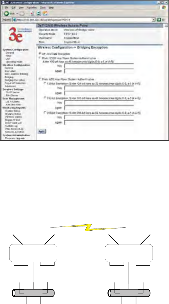
3e-531AP Wireless Access Point Chapter 5: Bridge Conguration
70 29000125-001 C
3e-531AP Wireless Access Point Chapter 5: Bridge Conguration
29000125-001 C 71
The following sections describe the setup for four types of bridging
conguration: point-to-point, point-to-multipoint, back-to-back or, lastly,
repeater.
Bridging Type Conguration
Point-to-Point Bridge Conguration
A point-to-point link is a direct connection between two, and only
two, locations or nodes.
Ethernet Ethernet
Bridge 1 Bridge 2

3e-531AP Wireless Access Point Chapter 5: Bridge Conguration
72 29000125-001 C
3e-531AP Wireless Access Point Chapter 5: Bridge Conguration
29000125-001 C 73
For the two bridges that are to be linked to communicate properly,
they have to be set up with compatible commands in the setup screens.
For instance, the bridges must have the same channel number. Both
must be set for bridging with Wireless Client Access set to Disable. Span-
ning Tree Protocol may be set to Enable, if there is any possibility of a
bridging loop, or to Disable (which is more efcient) if there's no possibil-
ity of a bridging loop. Each must contain the other's BSSID. (The BSSID of
each is equivalent to the MAC address. Enter only hexadecimal numbers,
no colons. Data entry is not case sensitive.) Finally, the wireless bridging
encryption must be set to the appropriate type and key length and must
be identical on each bridge.
The following chart shows the preferred settings.
Point-to-Point Bridging Setup Guide
Direction Bridge 1 Bridge 2
Mode Bridging Bridging
Wireless Conguration – General
SSID default default
Channel 11 11
Tx Power Auto Auto
Wireless Conguration – Encryption N/A N/A
Wireless Conguration – Bridging
Wireless Client Access Disable Disable
Spanning Tree Protocol Enable (or Disable if
no bridging loop pos-
sible)
Enable (or Disable if
no bridging loop pos-
sible)
BSSID (the MAC Address, from the
Wireless Conguration — General
screen.)
Add Bridge 2 BSSID Add Bridge 1 BSSID
Wireless Conguration – Bridging
Encryption
Select appropriate
key type/length and
value. Must be the
same key as Bridge 2.
Select appropriate
key type/length and
value. Must be the
same key as Bridge 1.
The following sequence steps you through the setup of bridge 1.
Bridge 2 would duplicate this procedure, with the BSSID of bridge 2 be-
ing the MAC address of bridge 1 and vice versa.
First, ensure that bridge 1 is in Bridging Mode by selecting that option
on the System Conguration — Operating Mode screen and clicking Ap-
ply to reboot.
Navigate to the Wireless Conguration — General screen and set the
Channel number. Leave the TX Pwr Mode in AUTO position at this time.
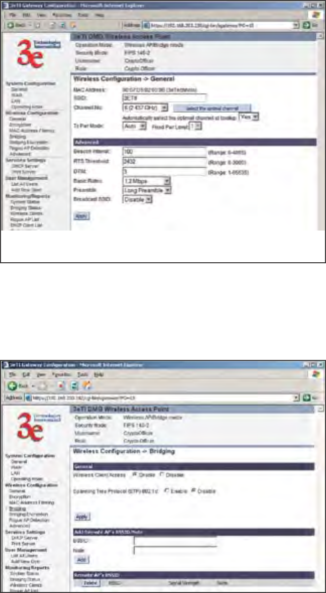
3e-531AP Wireless Access Point Chapter 5: Bridge Conguration
72 29000125-001 C
3e-531AP Wireless Access Point Chapter 5: Bridge Conguration
29000125-001 C 73
Navigate to the Wireless Conguration — Bridging screen.
In the rst section: General, set Wireless Client Access to Disable
and set Spanning Tree Protocol to Enable. Click Apply to accept your
changes but remain on that screen.
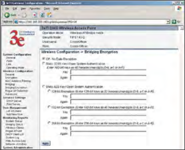
3e-531AP Wireless Access Point Chapter 5: Bridge Conguration
74 29000125-001 C
3e-531AP Wireless Access Point Chapter 5: Bridge Conguration
29000125-001 C 75
In the second section on the Wireless Conguration — Bridging
screen, add the BSSID of the remote bridge. The BSSID corresponds to
that bridge's MAC address. In entering the BSSID, enter only hexadecimal
numbers, no colons. Data entry is not case sensitive. You may also enter
a note that denes the location of the remote bridge. Then click Add to
accept. The remote bridge's BSSID will now appear in the third section of
the page. If, at some time, you wish to delete the entry, simply click the
check box next to it and conrm by clicking Delete.
Next, navigate to Wireless Conguration — Bridging Encryption.
Select the appropriate key type and length and the key value. The encryp-
tion key value and type for Bridge 1 must be the same as for Bridge 2.
You must complete the conguration of your Bridge 1 by visiting the
other screens included in the navigation bar and following the general
instructions in Chapter 3 of this guide to establish any other required con-
guration options such as General, WAN and LAN settings.
Congure the second of your two point-to-point bridges following the
instructions given for Bridge 1 above.
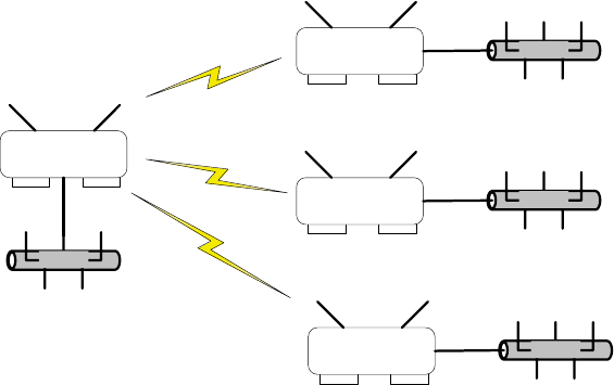
3e-531AP Wireless Access Point Chapter 5: Bridge Conguration
74 29000125-001 C
3e-531AP Wireless Access Point Chapter 5: Bridge Conguration
29000125-001 C 75
Point-to-Multipoint Bridge Conguration
A point-to-multipoint conguration allows you to set up three or
more 3e-531AP access points in bridging mode and accomplish bridging
between 3 or more locations wirelessly.
For the three bridges that are to be linked to communicate properly,
they have to be set up with compatible commands in their setup screens.
For instance, all bridges must have the same channel number. All
must be set for bridging with Wireless Client Access set to Disable and
Spanning Tree Protocol usually set to Enable. If congured as in the dia-
gram below, Bridge 1 must contain all of the others' BSSIDs, while Bridge
2 ~ n must only contain Bridge 1's BSSID. (The BSSID of each is equiva-
lent to the MAC address. Enter only hexadecimal numbers, no colons.
Data entry is not case sensitive.) Finally, the wireless bridging encryption
of each must be set to the appropriate type and key length and must be
the same on all.
The following diagram pictures a point-to-multipoint setup, which
might be of use where a company's network spans several buildings
within a campus-like setting.
Ethernet
Ethernet
Bridge 1
Bridge 2
Ethernet
Bridge 3
Ethernet
Bridge 4
Follow the steps of the procedure outlined in the point-to-point bridge
section. The chart below describes the basic attributes.
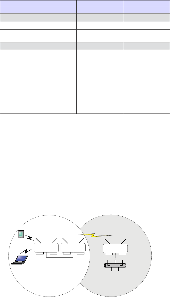
3e-531AP Wireless Access Point Chapter 5: Bridge Conguration
76 29000125-001 C
3e-531AP Wireless Access Point Chapter 5: Bridge Conguration
29000125-001 C 77
Point-to-Multipoint Bridging Setup Guide
Direction Bridge 1 Bridge 2 ~ n
Mode Bridging Bridging
Wireless Conguration – General
SSID default default
Channel 6 6
Wireless Conguration – Encryption N/A N/A
Wireless Conguration – Bridging
Wireless Client Access Disable Disable
Spanning Tree Protocol Enable (or Disable if
no bridging loop pos-
sible)
Enable (or Disable if
no bridging loop pos-
sible)
BSSID (the MAC Address, from the
Wireless Conguration — General
screen.)
Add Bridge 2 ~ n BS-
SIDs
Add Bridge 1 BSSID
Wireless Conguration – Bridging
Encryption
Select appropriate
key type/length and
value. Must be the
same key as Bridge
2~n.
Select appropriate
key type/length and
value. Must be the
same key as Bridge 1.
The above recommended setup requires only Bridge 1 to be set in
point-to-multipoint mode. It is possible to set all bridges in point-to-
multipoint mode, in which case , each bridge would have to contain the
BSSID for each of the other bridges and Spanning Tree Protocol must be
Enabled.
As stated previously, complete any other setup screens following gen-
eral instructions in Chapter 3.
Back-to-Back Bridge Conguration
A back-to-back conguration could be of use when it is desirable to
have a mobile unit able to communicate with an Ethernet LAN. As shown
in the following diagram, this does require the use of an additional AP
for managing local wireless communications at the mobile site, but may
be desired for emergency or security reasons.
Ethernet
Bridge 1 Bridge 2
PDA
Laptop
Access Point

3e-531AP Wireless Access Point Chapter 5: Bridge Conguration
76 29000125-001 C
3e-531AP Wireless Access Point Chapter 5: Bridge Conguration
29000125-001 C 77
The following chart maps the basic procedure to be followed in con-
guring the three units as shown above. Essentially, you can follow the
procedure as laid out in the section on point-to-point bridging. It is the
BSSID and the Bridging Encryption that allows the two bridges to com-
municate. Needless to say, the conguration of the access point deter-
mines the functioning of the dependent WLAN.
Back-to-Back Bridging Setup Guide
Direction Access Point Bridge 1 Bridge 2
Mode Access Point Bridging Bridging
Wireless Conguration – General
SSID SSID to be used for
the local WLAN
Different from
AP (can be left in
Default)
Different from
AP (can be left in
Default)
Channel 11 1 1
Wireless Congura-
tion – Encryption
Congure Dynamic
Key Fields with
your server's IP
address and pass-
word
N/A N/A
Wireless Conguration – Bridging
Wireless Client Ac-
cess
N/A Disable Disable
Spanning Tree Pro-
tocol
N/A Enable Enable
BSSID (the MAC Ad-
dress, from the Wire-
less Conguration
— General screen.)
N/A Add Bridge 2 BSSID Add Bridge 1 BS-
SID
Wireless Congu-
ration – Bridging
Encryption
N/A Select appropriate
key type/length
and value. Must
be the same key as
Bridge 2.
Select appropriate
key type/length
and value. Must
be the same key as
Bridge 1.
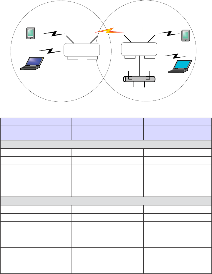
3e-531AP Wireless Access Point Chapter 5: Bridge Conguration
78 29000125-001 C
Repeater Bridge Conguration
A repeater setup can be used to extend the wireless signal from one
bridge connected to an Ethernet LAN wirelessly so that another bridge
can control a wireless LAN at a distance.
Ethernet
Bridge 1 Bridge 2
PDA
Laptop
PDA
Laptop
Repeater Bridging Setup Guide
Direction Bridge 1 Bridge 2
System Conguration
– Operating Mode
Bridge Bridge
Wireless Conguration – General
SSID Same as Bridge 2 Same as Bridge 1
Channel 6 6
Wireless Conguration
– Encryption
Congure Dynamic Key
Management elds with
your server's IP address and
password. (Alternately, use
a static key.)
Congure Dynamic Key
Management elds with
your server's IP address
and password. (Alternate-
ly, use a static key.)
Wireless Conguration – Bridging
Wireless Client Access Enable Enable
Spanning Tree Protocol Enable Enable
BSSID (the MAC Ad-
dress, from the Wireless
Conguration — General
screen.)
Add Bridge 2's BSSID Add Bridge 1's BSSID
Wireless Conguration
– Bridging Encryption
Select appropriate key type/
length and enter key value.
Must be the same as that on
Bridge 2.
Select appropriate key
type/length and enter key
value. Must be the same as
that on Bridge 1.
With this conguration, each bridge can control a wireless LAN. All
wireless clients must have the same SSID as the bridges. All clients can
roam between the two bridges.
All other setup screens should be completed following the guidelines
in Chapter 3.

3e-531AP Wireless Access Point Chapter 6: PC Card Installation on a Laptop
29000125-001 C 79
Chapter 6: PC Card Installation on a Laptop
If you are setting up the 3e-531AP as part of a secure wireless LAN us-
ing AES or 3DES encryption options, you need to purchase and install an
IEEE 802.11b PC Card on each laptop that will be a client on the network.
The laptop must have a PCMCIA Card Type II or Type III slot. You will
need to install the 3e-010 Crypto Client Software (separately sold with the
3e-110 Wireless PC Card).
3e Technologies International’s 3e-010F Crypto Client Software is
compatible with the 3e-110 Wireless PC Card and with other wireless
cards based on INTERSIL PRISM 2 and 2.5 chipsets. It will install in a
Windows 2000, Windows NT 4.0 or Windows XP operating system envi-
ronment.
If you will be using the 3e-531AP with WEP encryption only, you can
use any compatible PC Card.
Follow the manuafacturer's instructions to complete installing the PC
Card.
Once the PC Card is installed, you must now congure the encryption
utility to allow the user access to the WLAN. Until the utility has been
congured to allow access to the 3e-531AP, you will not be able to access
the WLAN from the particular wireless device you are conguring.
If you are using the 3e-110 PC Card with secure 3e-010F AES or 3DES
encryption software, there are two types of roles on the secure system:
CryptoOfcer and Administrator. The following chart shows the different
permissions in respect to the Crypto Client Utility.
Activity CryptoOfcer Administrator
Identier (factory setting) CryptoOfcer
CryptoFIPS
Admin
AdminFIPS
Ability to set Passwords P (all) P (only self)
Congures Crypto Client Utility Pû
Congures encryption settings Pû

3e-531AP Wireless Access Point Chapter 6: PC Card Installation on a Laptop
80 29000125-001 C
Performs Site Survey Pû
Resets to factory default Pû
Changes power level on Client device
(laptop)
P P
Can turn Radio On/Off on laptop P P
Performs Rescan P P
Performs Self-test P P
You may need some or all of the following information handy as you
install the FIPS secure drivers on your wireless device’s PC Card inter-
face:
• The driver conguration utility login. The factory default is User-
name equal to "CryptoOfcer,” and Userid equal to “CryptoFIPS;”
• Type of encryption used by your WLAN (AES, 3DES, and wheth-
er you will be using Dynamic Key Exchange);
• Your security certicate, key and Certicate Authority (CA), if us-
ing DKE;
• Your Wireless SSID;
• Your user name and password to access your network account on
the wireless device;
and, if addresses are to be statically assigned:
• Your IP address;
• Your Gateway address;
• Your Subnet Mask.
Follow the instructions that came with your PC Card to complete the
installation. Once the conguration is complete, you should be able to ac-
ces the WLAN.
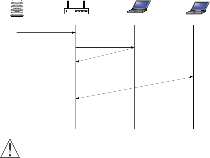
3e-531AP Wireless Access Point Chapter 7: The RF Manager Function
29000125-001 C 81
Chapter 7: The RF Manager Function
Introduction
his chapter addresses a function of the 3e AP which facilitates remote
management and programming of the Radio Frequency function for mul-
tiple 3e APs located on a common network. This function allows you to
remotely manage the Radio Frequency Power levels. For each AP select-
ed, the RF Manager can remotely disable the AP's transmit power and, in
turn, the transmit power of each client that is associated with it. The basic
architecture is shown in the chart below.
CAUTION: You can not use this utility if you are using dynamic
IP address assignment on your wireless network. We recommend that
you have your LAN Administrator set a range of static IP Addresses
and that you change the WAN IP Address on each gateway to one of
this range of IP Addresses as part of your setup process.
RF Manager
Disable Tx Power
Client 1: Disable Tx Power
Client 2: Disable Tx Power
Client 2: Acknowledges
Disabling Power
Client 1: Acknowledges
Disabling Power
~
~10 seconds after
RF Manager Request
Client 1 Disables Power
Client 2 Disables Power
AP Disables Power
Access Point Client 1 Client 2

3e-531AP Wireless Access Point Chapter 7: The RF Manager Function
82 29000125-001 C
3e-531AP Wireless Access Point Chapter 7: The RF Manager Function
29000125-001 C 83
How to Access the RF Manager Function
The RF Manager can be installed from the CD that came with the
3e-531AP Install Kit to the desktop of anyone who needs to manage the
wireless LAN.
Click on RF Manager on the CD main menu to start the autoinstall. If,
for any reason, the autoinstall doesn't initiate, open a window from the
My Computer icon to your CD drive and double-click the autoinstall icon
in the RF Manager folder on the CD.
Once the RF Manager is installed, use the path Start -> Programs ->
3e-RF Manager and click on 3e-RF Manager.
The main RF Manager screen will appear on your desktop.
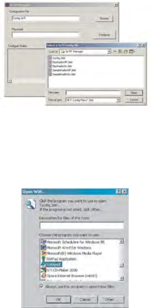
3e-531AP Wireless Access Point Chapter 7: The RF Manager Function
82 29000125-001 C
3e-531AP Wireless Access Point Chapter 7: The RF Manager Function
29000125-001 C 83
How to Program the RF Manager
Before you are able to remotely manage access points, you need to
program the RF Manager by putting the static IP Address of APs you
want to manage in a conguration le.
Click on the Browse button. This will open a window with
some sample les that you can edit. You should edit the contents of
SampleRadioOn.3eti and SampleRadioOff.3eti.
To see the contents of one of these les, simply right click the le
name and select Open from the dropdown menu.
Because the le has an extension (3eti) which Windows is not yet
familiar with, the very rst time you attempt to open it, Windows will ask
you what program you want to open it with, as shown in the following
screen. Choose a text editor that you are comfortable with, such as Word-
pad. In future, Windows will open all les with the extension of 3eti with
the text editor you have chosen. You will be able to edit the le and save it
without changing the le properties.
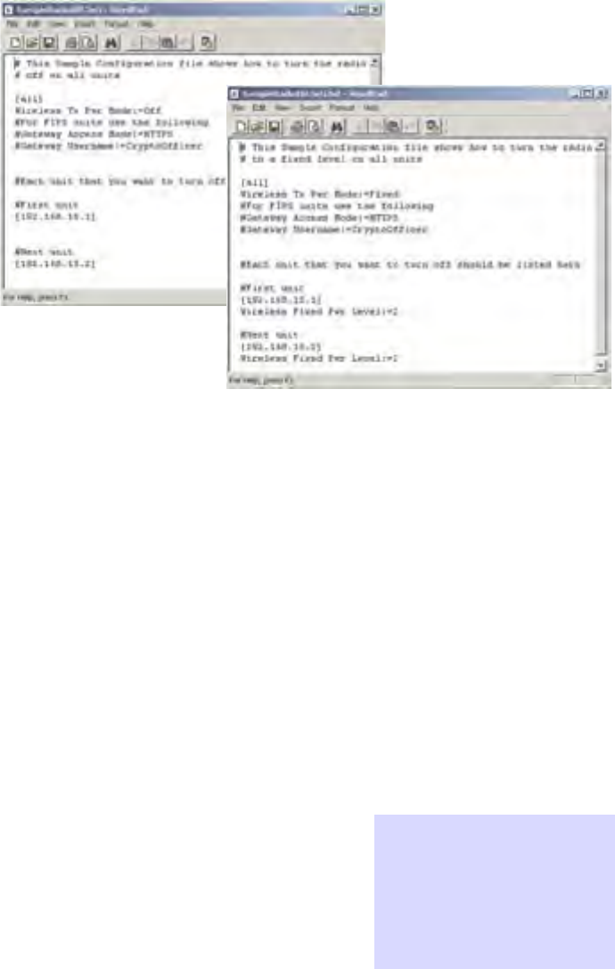
3e-531AP Wireless Access Point Chapter 7: The RF Manager Function
84 29000125-001 C
3e-531AP Wireless Access Point Chapter 7: The RF Manager Function
29000125-001 C 85
You can now edit the le by adding the IP addresses of the 3e-531APs
that you want to manage, each in a pair of brackets [ ].
The two les SampleRadioOn.3eti and SampleRadioOff.3eti must be
edited as a minimum. This will permit you to turn all the APs on or off at
will. You can save them to another le name if you wish (maintaining the
same le extension.)
You can customize les to control only certain APs or groups of APs.
Each AP that you group into a conguration le must have the same Ad-
min Password.
The following gives you a sample of the code that you can use from
the SampleRadioOn.3eti le.
Sample of coding in SampleRadioOn.3eti le
# This Sample Conguration le shows how to turn the radio
# to a xed level on all units
[all]
Wireless Tx Pwr Mode:=Fixed
#For FIPS units use the following
#Gateway Access Mode:=HTTPS
#Gateway Username:=CryptoOfcer
#Each unit that you want to turn on should be listed here
#First unit
[192.168.15.1]
Wireless Fixed Pwr Level:=2
#Next unit
[192.168.15.2]
Wireless Fixed Pwr Level:=2
Important: you must
remove the pound
sign (#) from in front
of any line that you
want to be "read" by
the program.
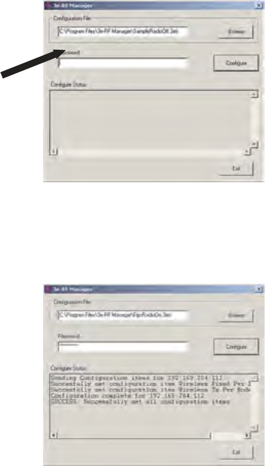
3e-531AP Wireless Access Point Chapter 7: The RF Manager Function
84 29000125-001 C
3e-531AP Wireless Access Point Chapter 7: The RF Manager Function
29000125-001 C 85
Once you have edited the le, save it. You can now update the APs
you have included in your conguration les from an Ethernet connec-
tion on your network.
To test out the les you have edited, on the main RF Manager screen,
browse to and select the le that you want to use to manage your APs.
That le name should now appear in the Conguration File window.
Now enter the Password for that group of APs.
Finally, hit the Congure button.
The Congure Status window will keep you informed of the progress
of the update.
If your update has been successful, you should see a message that
indicates you have successfully set all conguration items.
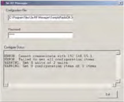
3e-531AP Wireless Access Point Chapter 7: The RF Manager Function
86 29000125-001 C
If any part of your update has failed, the Congure Status window
will show you that it has failed in part or in whole and direct you to the
area of the conguration le that you need to x.
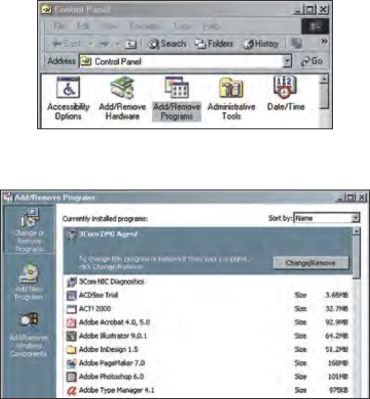
3e-531AP Wireless Access Point Chapter 8: Network Printer Setup
29000125-001 C 87
Chapter 8: Network Printer Setup
If you want to have the 3e AP operate as a printer server, connect a
printer to the wireless gateway now. The following instructions cover
how to set it up using Windows 2000 as your operating system. (See the
Troubleshooting chapter if you have Windows 95/98. Windows XP is
similar to Windows 2000.)
Install Print Service for Unix (Windows 2000):
1. Open the Control Panel and select Add/Remove Programs
2. In the Add/Remove Programs window, on the left navigation bar,
select Add/Remove Windows Components.
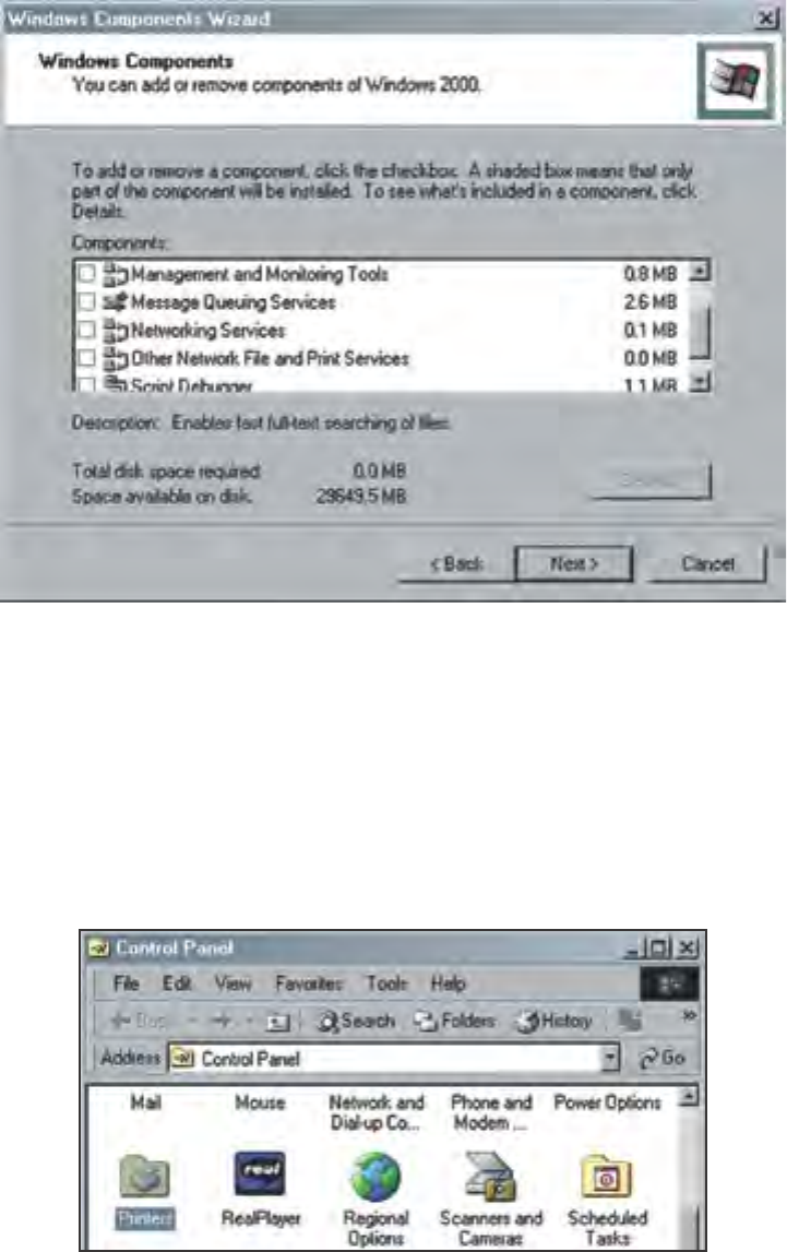
3e-531AP Wireless Access Point Chapter 8: Network Printer Setup
88 29000125-001 C
3e-531AP Wireless Access Point Chapter 8: Network Printer Setup
29000125-001 C 89
3. In the Add/Remove Windows Components wizard, select Other
Network File and Print Services.
4. Click Next and the wizard will install this component. You may
need your windows install CD.
5. Windows informs you that the action is complete. Click Finish and
close the prior screen.
Printer Setup
Now you are prepared to set up your new printer resource. Follow
this procedure:
1. Access the Control Panel and select the Printers icon as shown on
the following picture.

3e-531AP Wireless Access Point Chapter 8: Network Printer Setup
88 29000125-001 C
3e-531AP Wireless Access Point Chapter 8: Network Printer Setup
29000125-001 C 89
2. From the Printers window, select Add Printer.
3. The Add Printer Wizard starts. Click Next.
4. From the following screen, select Local Printer and uncheck the
selection: Automatically detect and install my Plug and Play
printer. Then click Next.
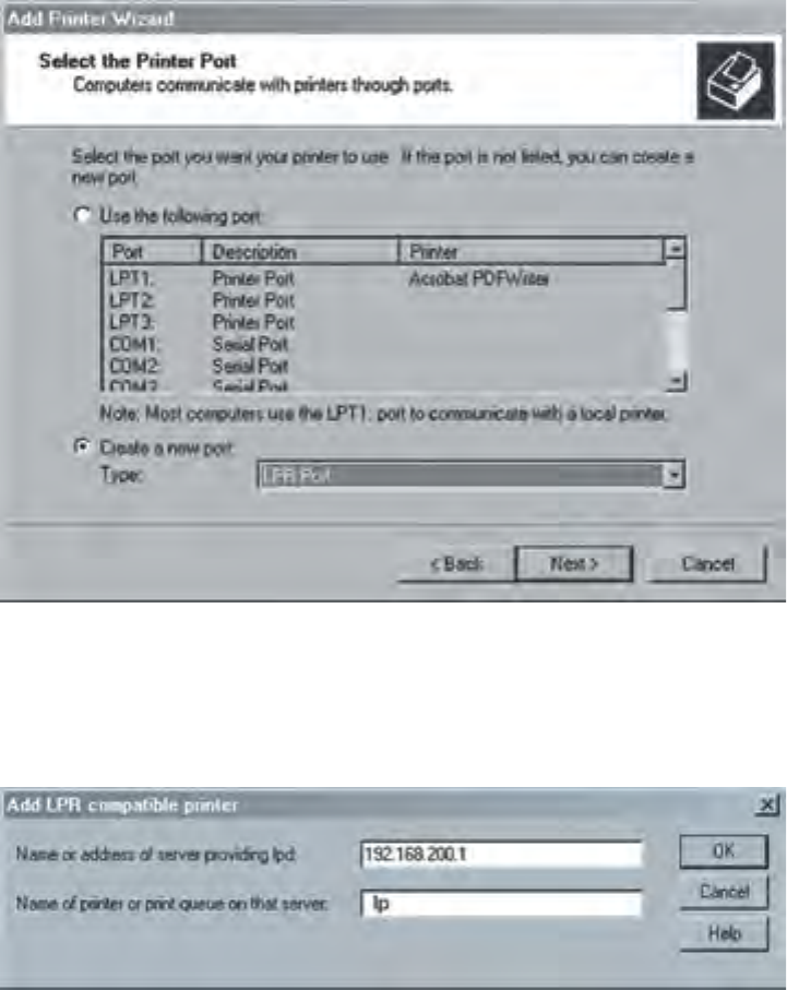
3e-531AP Wireless Access Point Chapter 8: Network Printer Setup
90 29000125-001 C
3e-531AP Wireless Access Point Chapter 8: Network Printer Setup
29000125-001 C 91
5. Select Create a new port and use the arrow to nd and highlight
LPR Port. Then click Next.
6. Next, in the eld for Name or address of the server providing lpd:
type the IP address assigned to the 3e-520 Gateway LAN. In the
eld for Name of printer or print queue on the server: type lp.
Then click OK.

3e-531AP Wireless Access Point Chapter 8: Network Printer Setup
90 29000125-001 C
3e-531AP Wireless Access Point Chapter 8: Network Printer Setup
29000125-001 C 91
7. In the next screen, locate rst the manufacturer for the printer you
are using, then the specic model of printer you are using. Then
click Next.
8. You will be asked to provide additional information. Continue
through the wizard screens until you reach the last. Then click Fin-
ish.
Important Note: On the Printer Sharing screen, do not select to
"share" the printer. The Access Point does the sharing, not the
printer.
It is a good idea to print a test page to conrm that the setup has been
successful. After you complete the printer’s setup, you will also need to
ensure that each device that needs to access the printer on the network is
properly congured by performing the procedure detailed above.
The above procedure applies to Windows 2000. Windows XP is simi-
lar. If you have another version of Windows, there are Microsoft sites that
will provide directions.
3e-531AP Wireless Access Point Chapter 8: Network Printer Setup
92 29000125-001 C
This page intentionally left blank.
3e-531AP Wireless Access Point Chapter 9: Technical Support
29000125-001 C 93
Chapter 9: Technical Support
Manufacturer’s Statement
The 3e-531AP is provided with warranty. It is not desired or expected
that the user open the device. If malfunction is experienced and all exter-
nal causes are eliminated, the user should return the unit to the manufac-
turer and replace it with a functioning unit.
If you are experiencing trouble with this unit, the point of contact is:
support@3eti.com
or visit our website at
www.3eti.com
Radio Frequency Interference Requirements
This device has been tested and found to comply with the limits for a
Class A digital device, pursuant to Part 15 of the Federal Communications
Commission’s Rules and Regulations. These limits are designed to pro-
vide reasonable protection against harmful interference when the equip-
ment is operated in a commercial environment. This equipment gener-
ates, uses, and can radiate radio frequency energy and, if not installed
and used in accordance with the instruction manual, may cause harmful
interference to radio communications. Operation of this equipment in a
residential area is likely to cause harmful interference in which case the
user will be required to correct the interference at his own expense.
Installation should be accomplished using the authorized cables
and/or connectors provided with the device or available from the
manufacturer/distributor for use with this device. Changes or modica-
tions not expressly approved by the manufacturer or party responsible for
this FCC compliance could void the user’s authority to operate the equip-
ment.
3e-531AP Wireless Access Point Chapter 9: Technical Support
94 29000125-001 C
This page intentionally left blank.
3e-531AP Wireless Access Point Glossary
29000125-001 C G-a
Glossary
802.11
802.11 refers to a family of specications developed by the IEEE for wireless LAN technol-
ogy. 802.11 species an over-the-air interface between a wireless client and a base station
or between two wireless clients. The IEEE accepted the specication in 1997.
802.11b (also referred to as 802.11 High Rate or Wi-Fi)
802.11b is an extension to 802.11 that applies to wireless LANs and provides 11 Mbps
transmission (with a fallback to 5.5, 2 and 1 Mbps) in the 2.4 GHz band. 802.11b uses only
DSSS. 802.11b was a 1999 ratication to the original 802.11 standard, allowing wireless
functionality comparable to Ethernet.
Access Point
An access point is a gateway set up to allow a group of LAN users access to another group
or a main group. The access point doesn’t use the DHCP server function and therefore ac-
cepts IP address assignment from the controlling network.
Bridge
A device that connects two local-area networks (LANs), or two segments of the same LAN
that use the same protocol, such as Ethernet or Token-Ring.
Certication Authority
An entity responsible for establishing and vouching for the authenticity of public keys
belonging to users (end entities) or other authorities. Activities of a certication author-
ity can include binding public keys to distinguished names through signed certicates,
managng certicate serial numbers, and certicate revocation.
DHCP
Short for Dynamic Host Conguration Protocol, DHCP is a protocol for assigning dy-
namic IP addresses to devices on a network. With dynamic addressing, a device can have
a different IP address every time it connects to the network. In some systems, the device’s
IP address can even change while it is still connected. DHCP also supports a mix of
static and dynamic IP addresses. Dynamic addressing simplies network administration
because the software keeps track of IP addresses rather than requiring an administrator to
manage the task. This means that a new computer can be added to a network without the
hassle of manually assigning it a unique IP address. Many ISPs use dynamic IP addressing
for dial-up users.
DMA
An abbreviation of Direct Memory Access, DMA is a technique for transferring data from
main memory to a device without passing it through the CPU. Computers that have
DMA channels can transfer data to and from devices much more quickly than computers
without a DMA channel can. This is useful for making quick backups and for real-time
applications.
DMZ
A DMZ (Demilitarized Zone) is used by a company that hosts its own Internet services. It
sits between the Internet and the internal network. It is a combination of rewalls and bas-
3e-531AP Wireless Access Point Glossary
G-b 29000125-001 C
tion hosts. Typically, the DMZ contains web servers, FTP servers, SMTP (email) servers,
and DNS servers.
NAT (Network Address Translation)
an Internet standard that enables a local-area network (LAN) to use one set of IP addresses
for internal trafc and a second set of addresses for external trafc.
NMS (Network Management Station)
Includes such management software as HP Openview and IBM Netview.
PCMCIA
Short for Personal Computer Memory Card International Association, and pronounced
as separate letters, PCMCIA is an organization consisting of some 500 companies that has
developed a standard for small, credit card-sized devices, called PC Cards. Originally
designed for adding memory to portable computers, the PCMCIA standard has been
expanded several times and is now suitable for many types of devices.
PC Card
A computer device packaged in a small card about the size of a credit card and con-
forming to the PCMCIA standard.
PDA (Personal Digital Assistant)
A handheld device.
SNMP
Simple Network Management Protocol
SSID
A Network ID unique to a network. Only clients and access points that share the same
SSID are able to communicate with each other. This string is case-sensitive. Wireless LANs
offer several security options, but increasing the security also means increasing the time
spent managing the system. Encryption is the key. The biggest threat is from intruders
coming into the LAN. You set a seven-digit alphanumeric security code, called an SSID, in
each wireless device and they thereafter operate as a group.
VPN (Virtual Private Network)
A VPN uses encryption and other security mechanisms to ensure that only authorized us-
ers can access the network and that the data cannot be intercepted.
WLAN (Wireless Local Area Network)
A type of local-area network that uses high-frequency radio waves rather than wires to
communicate between nodes.