4IPNET 090001 IEEE802.11 b/g Outdoor AP/Bridge (Support IEEE802.11a Client Backhaul) User Manual
4IPNET, INC. IEEE802.11 b/g Outdoor AP/Bridge (Support IEEE802.11a Client Backhaul)
UserManual.wiki
>
4IPNET
>
090001 User Manual
User manual
Navigation menu
Upload a User Manual
Namespaces
Wiki Guide
HTML
PDF
Info
Views
User Manual
Discussion / Help
Navigation
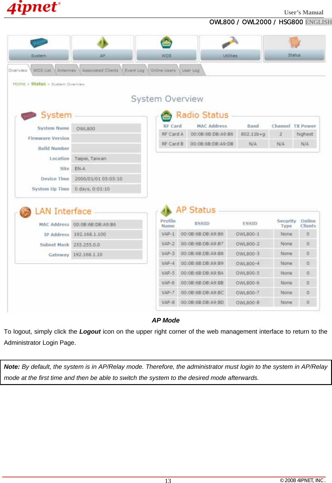
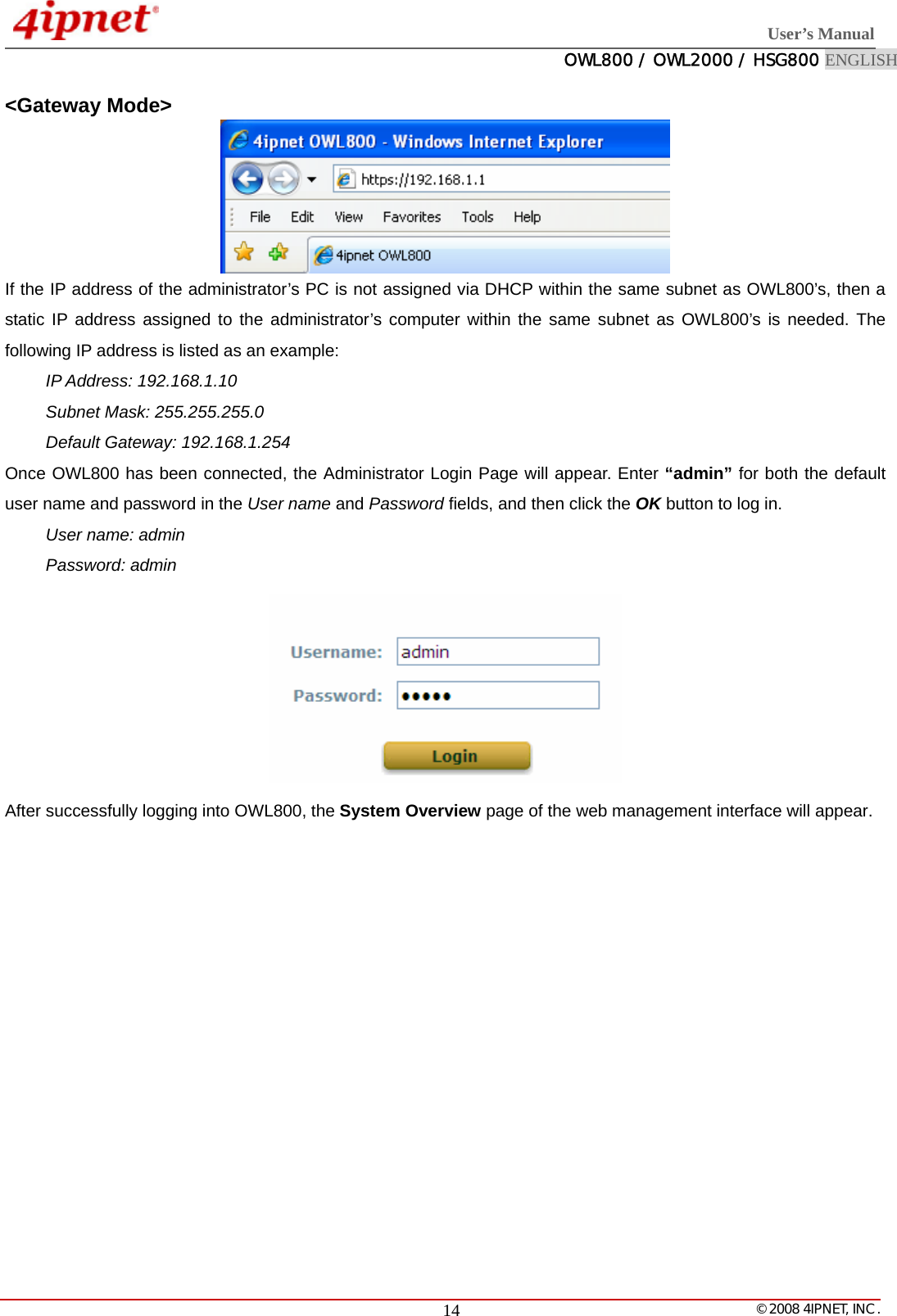
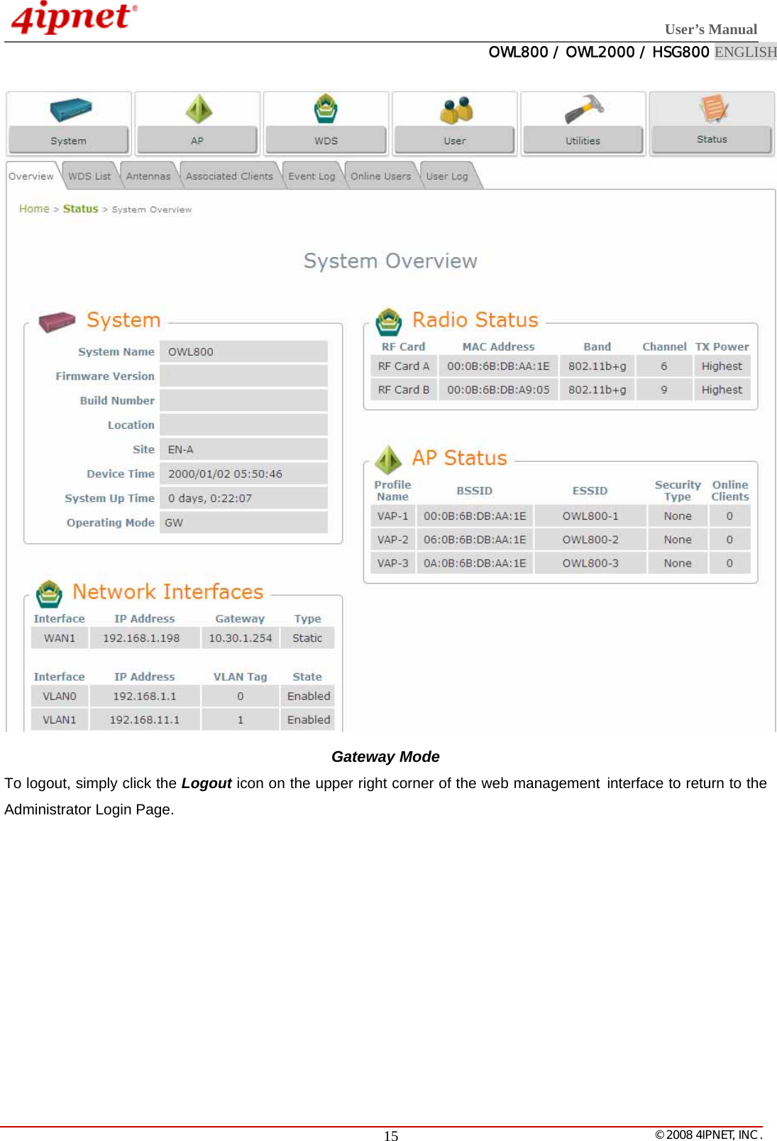
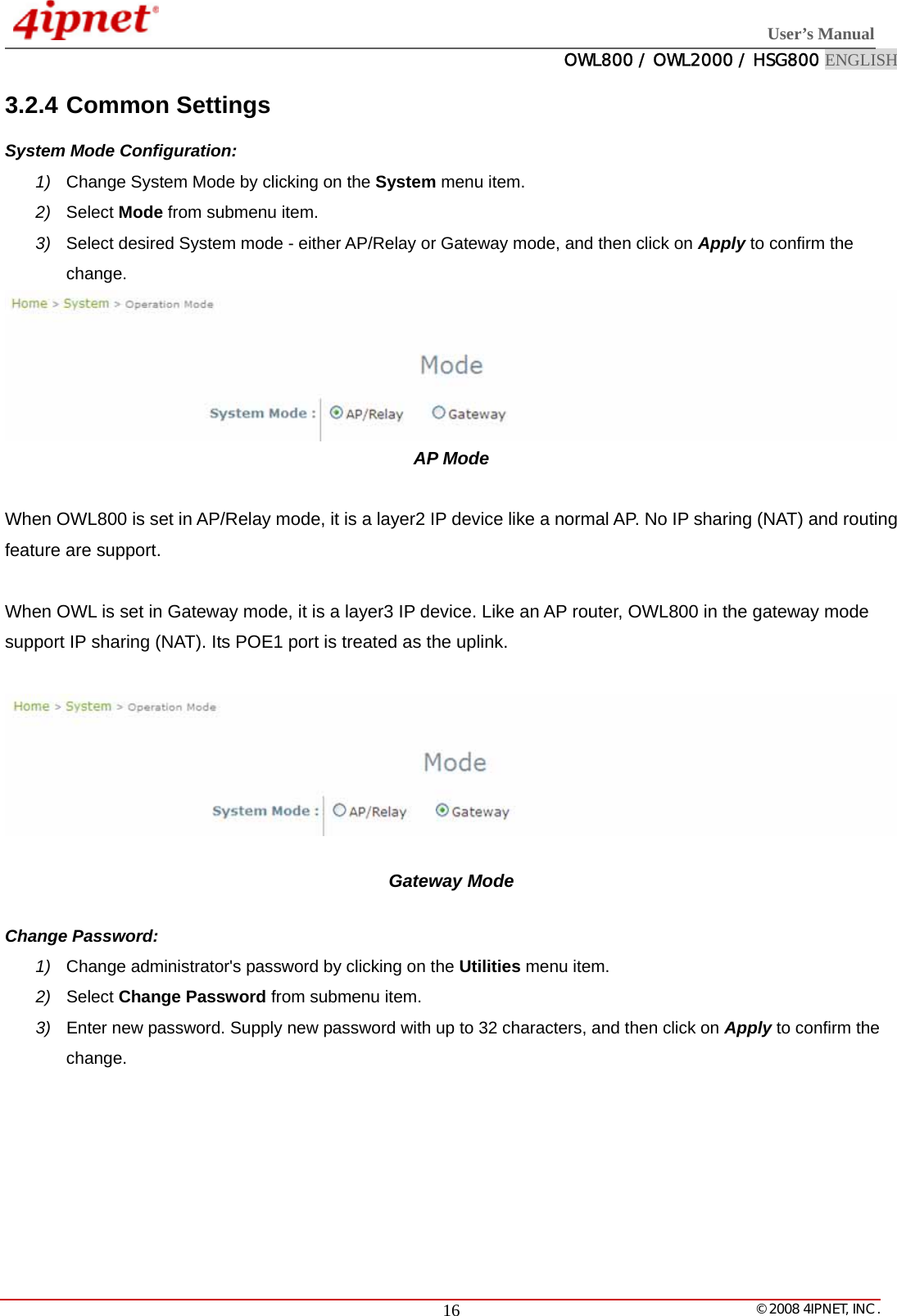
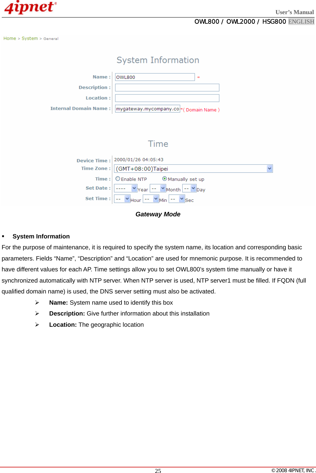
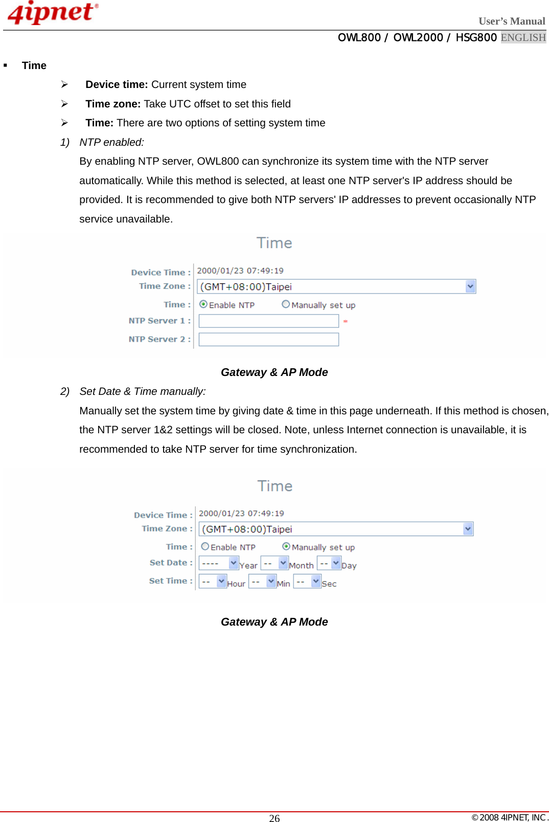
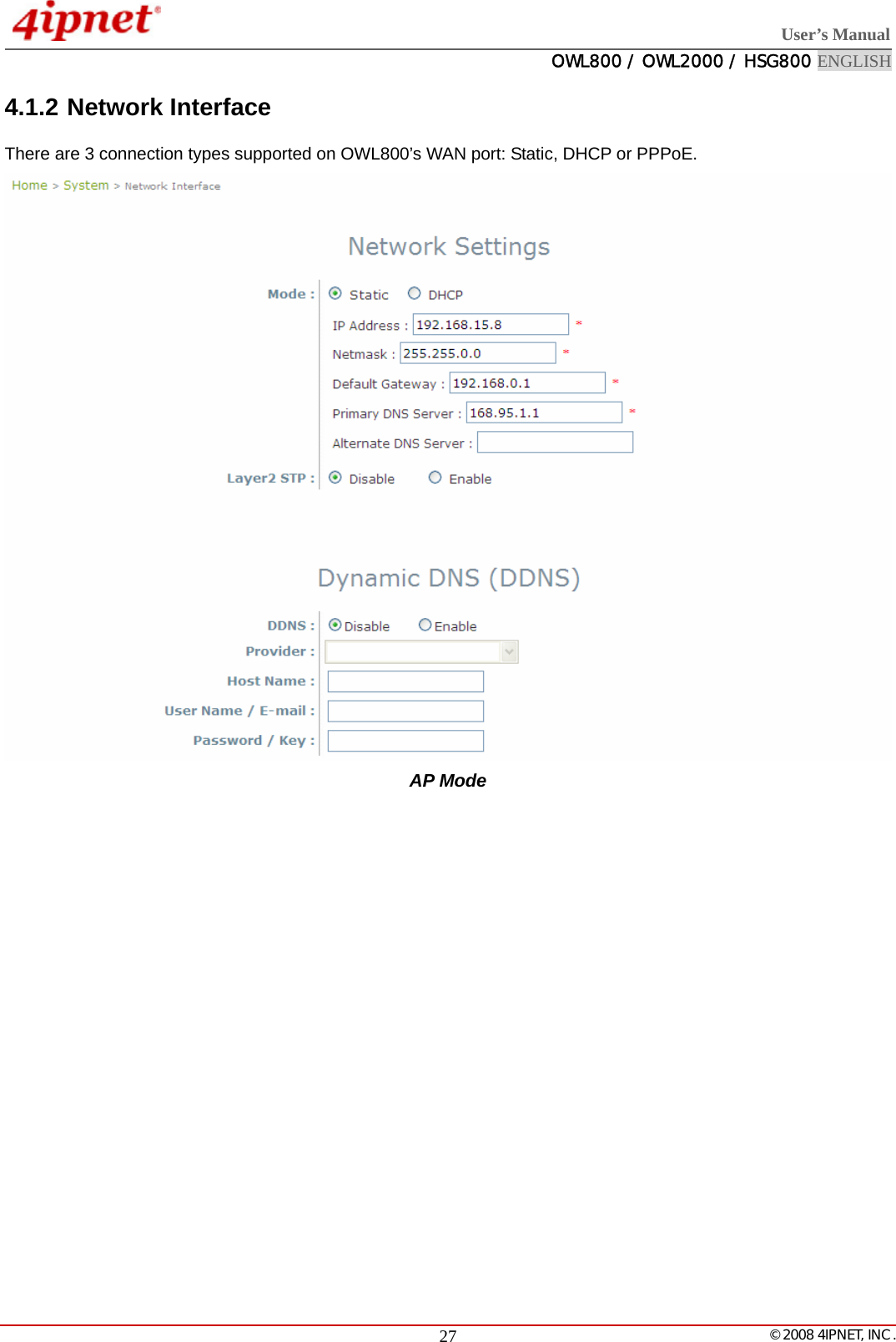
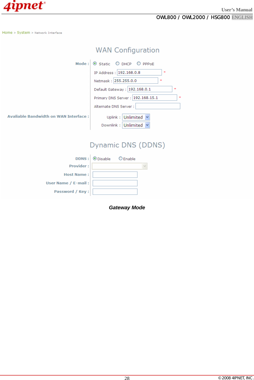
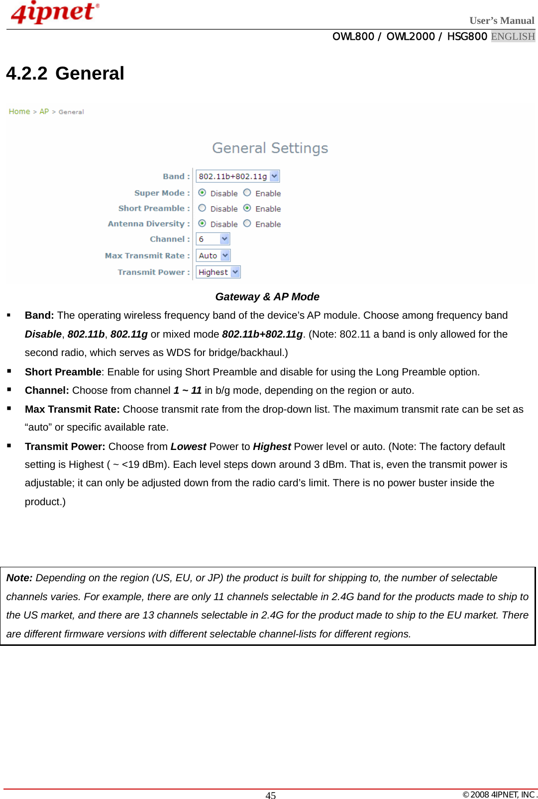
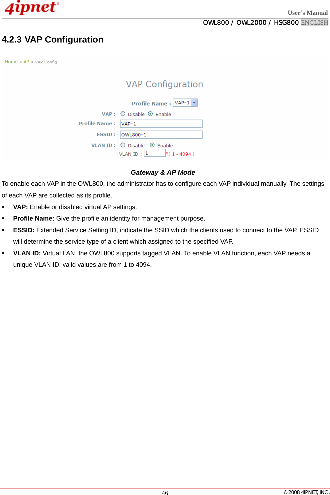
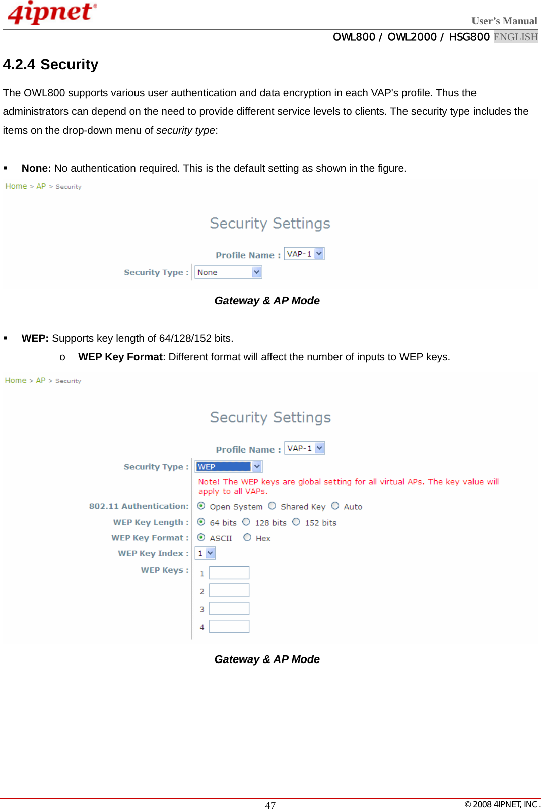
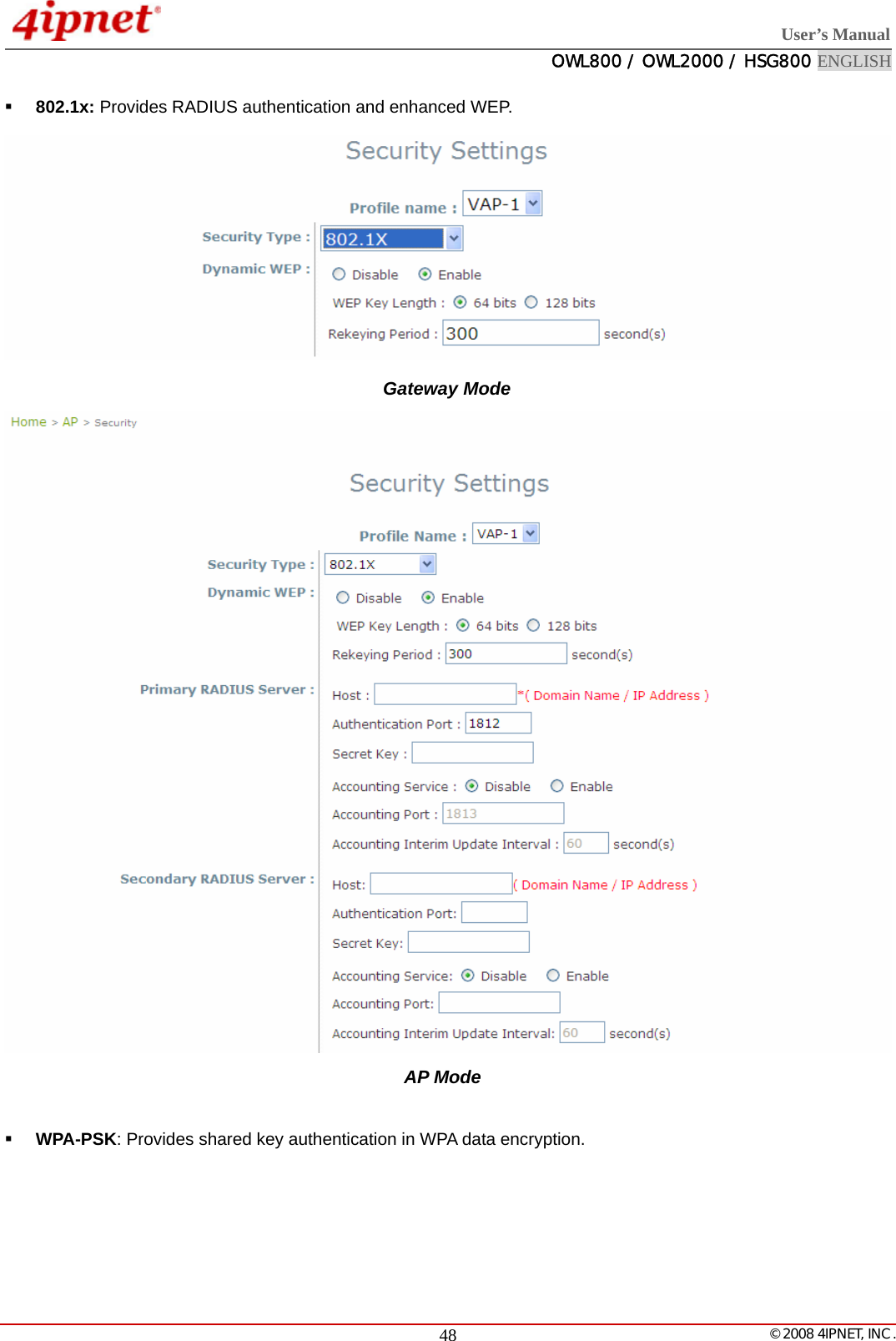
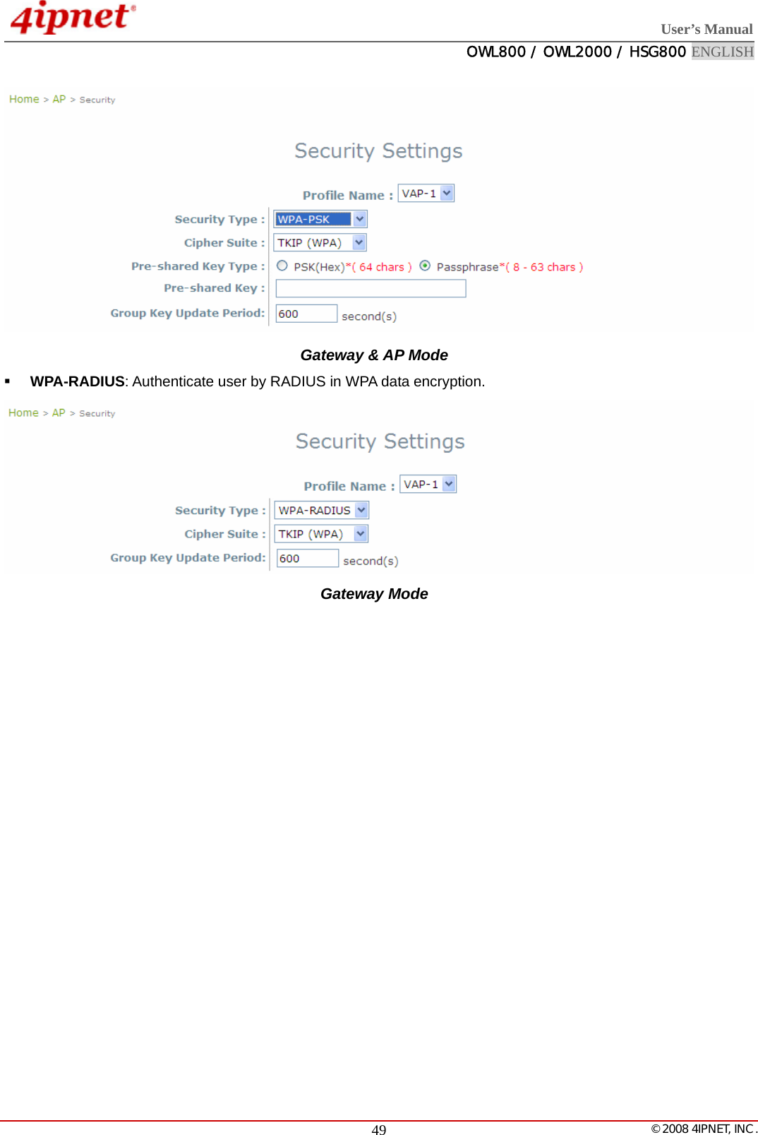
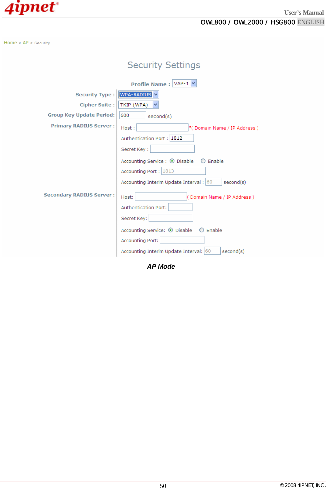
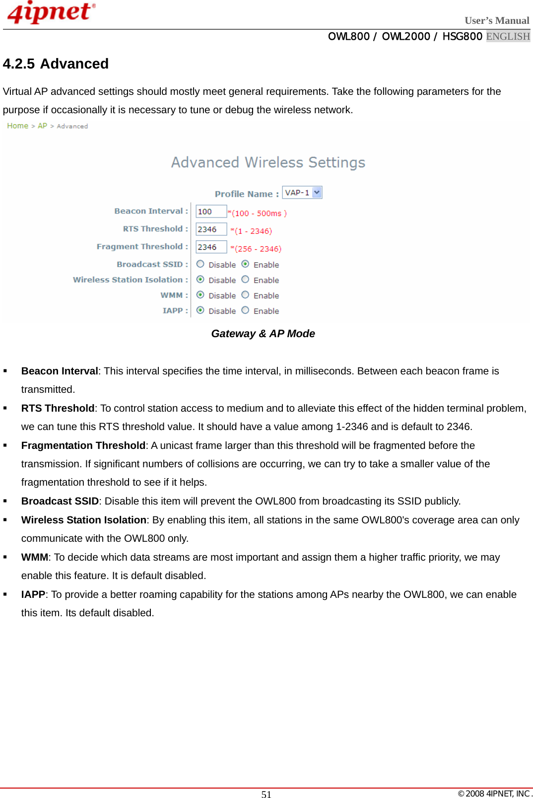
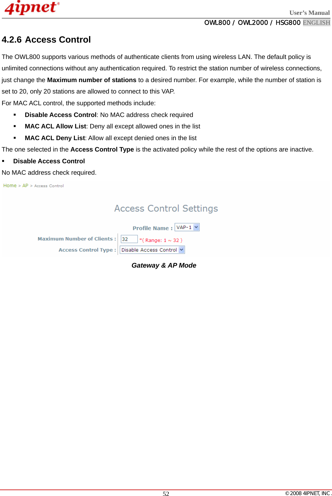
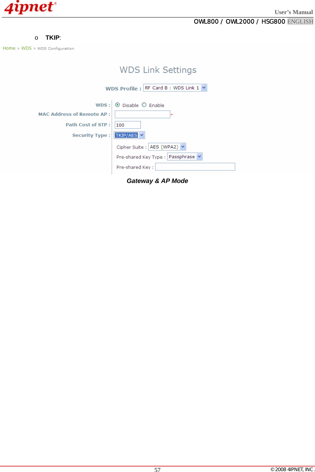
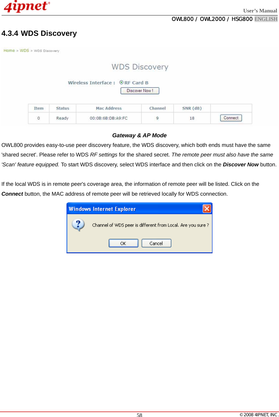
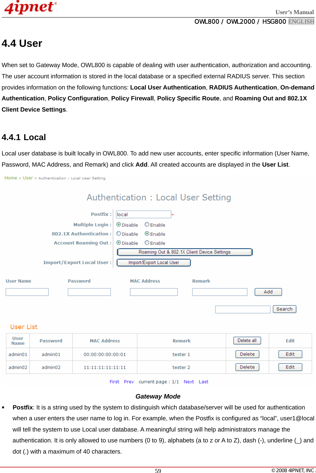
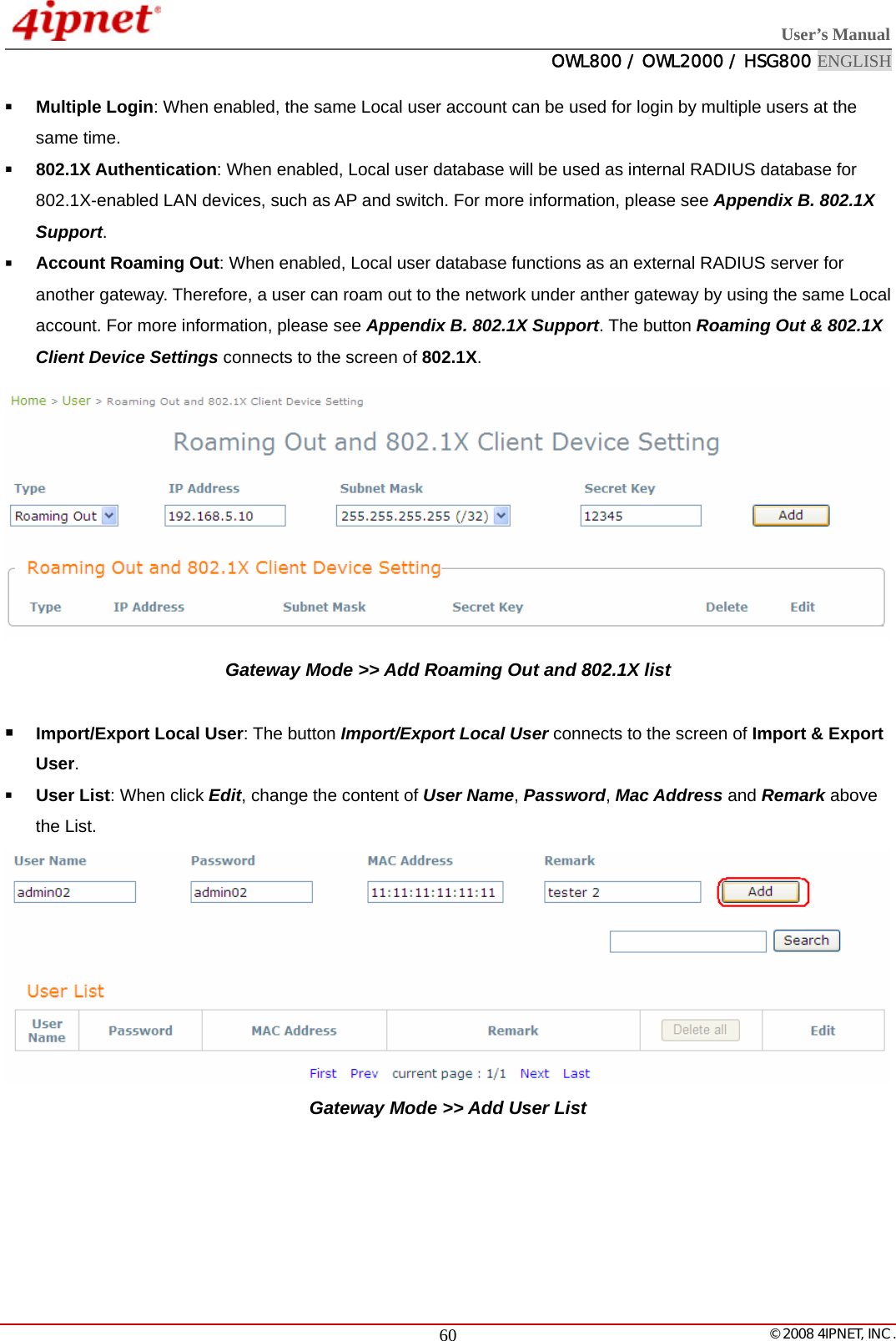
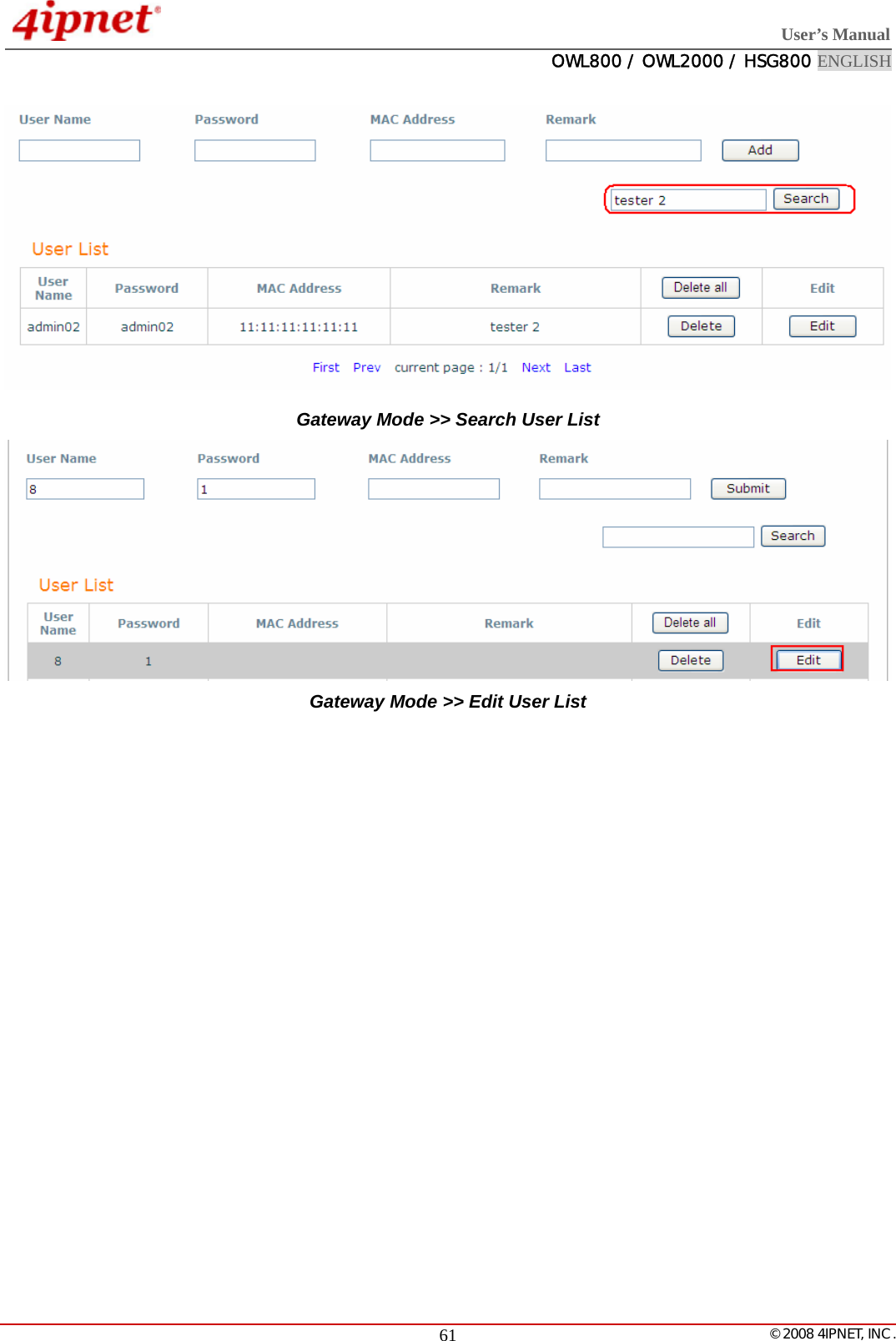
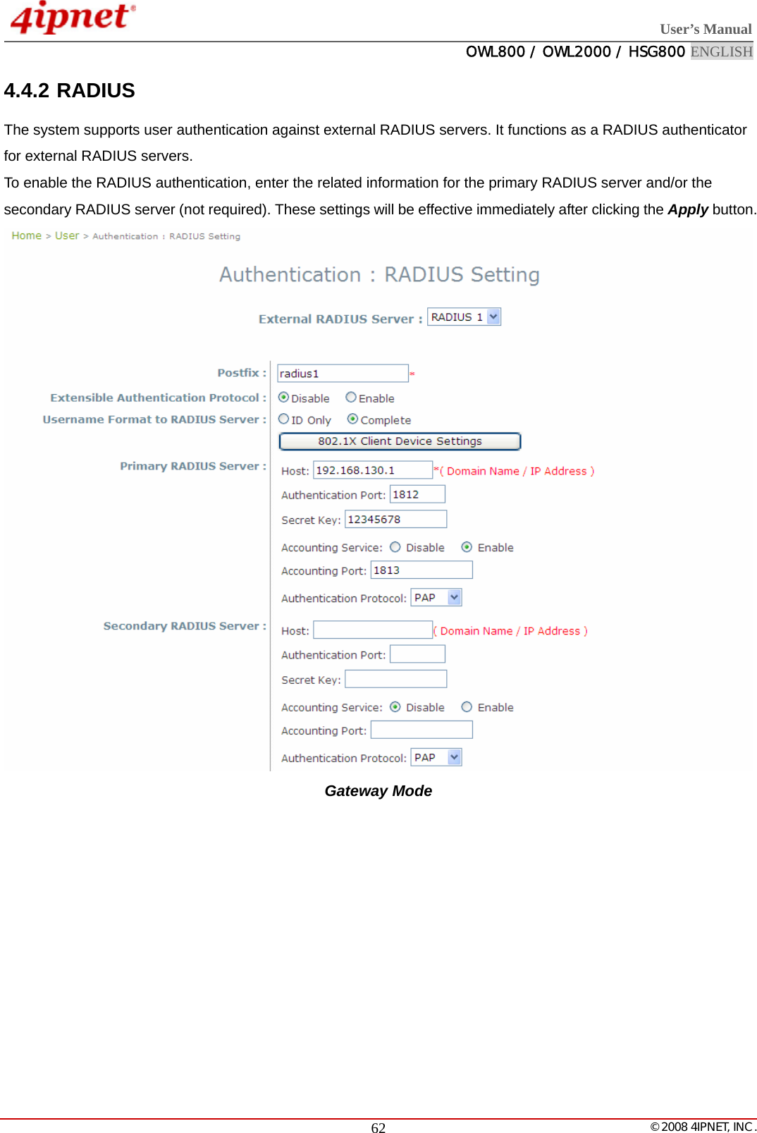
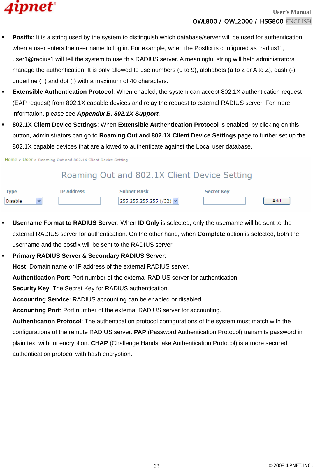
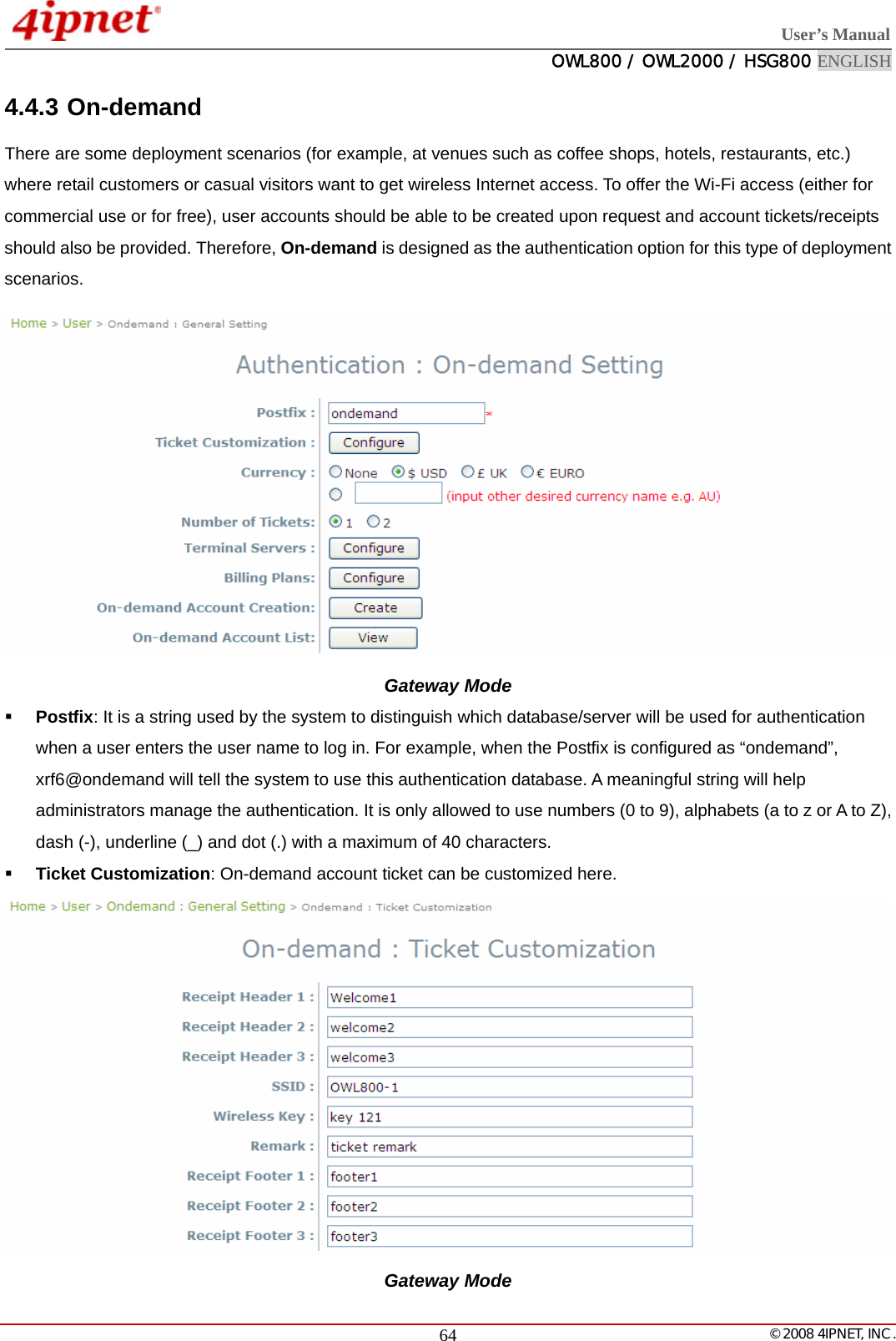
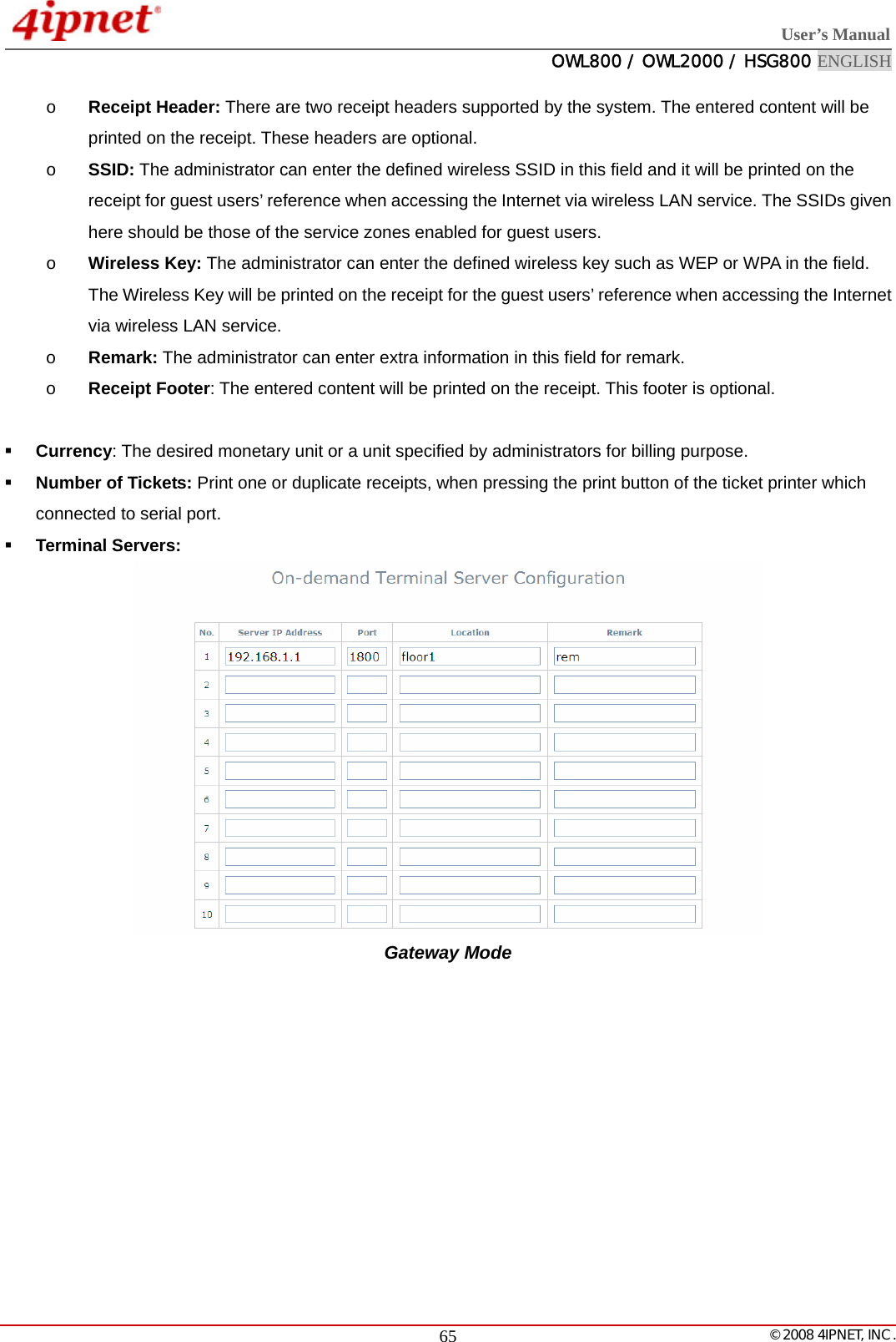
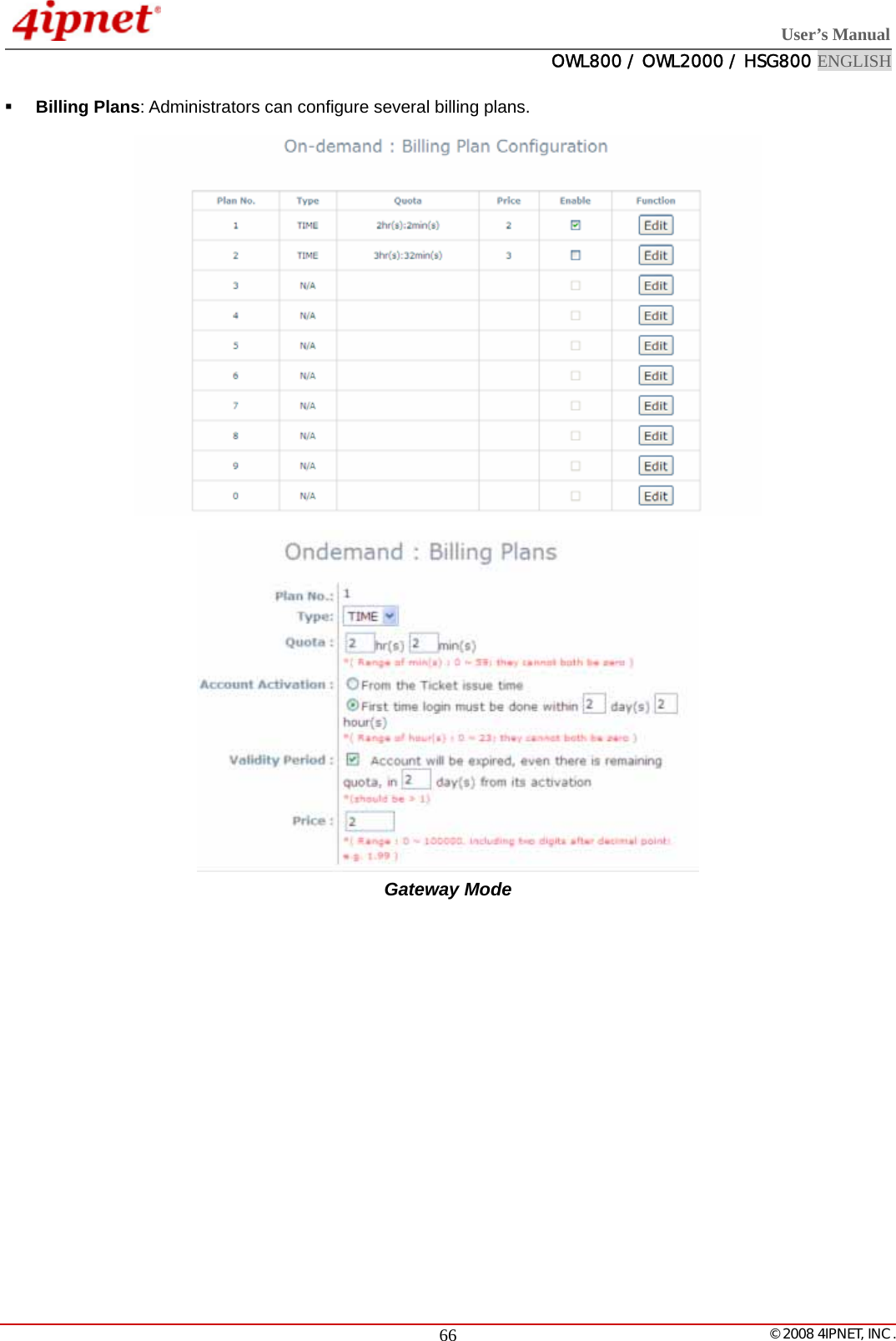
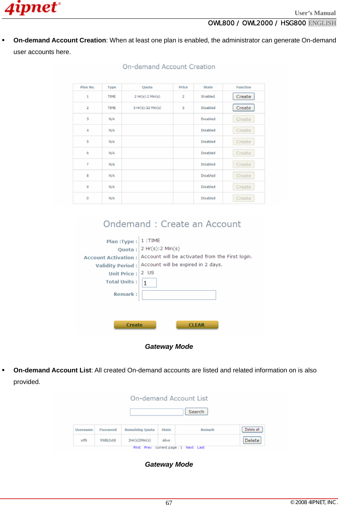
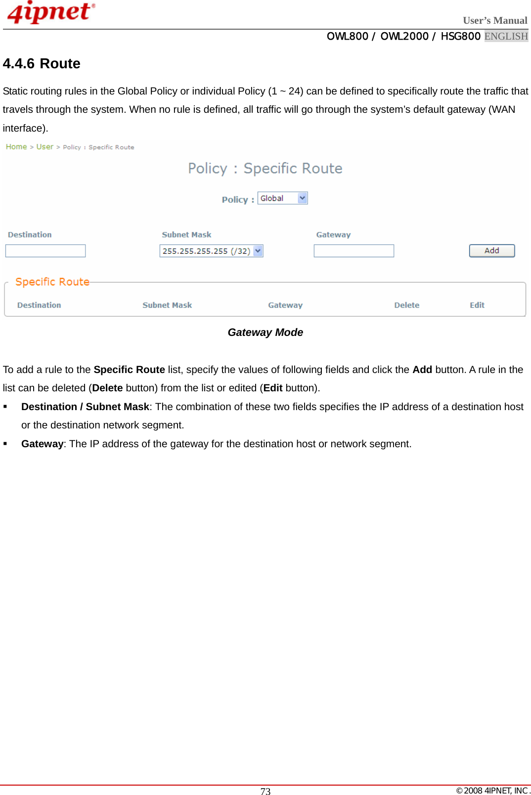
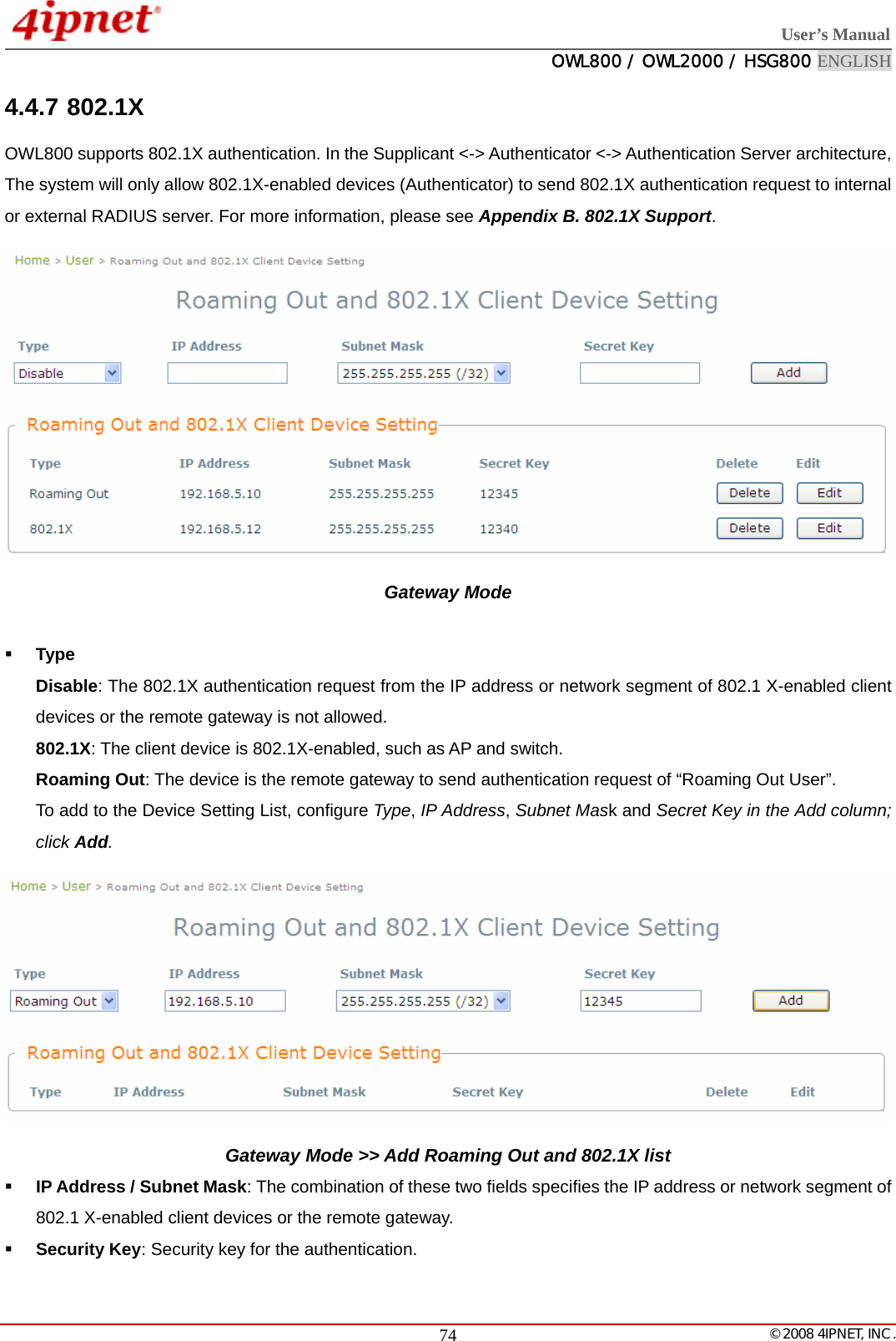
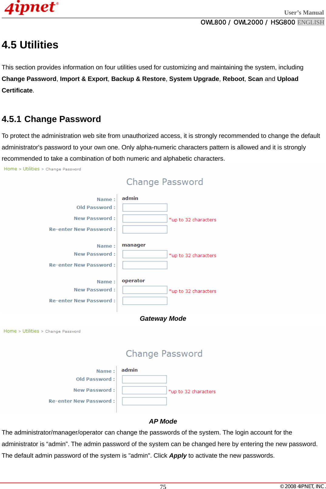
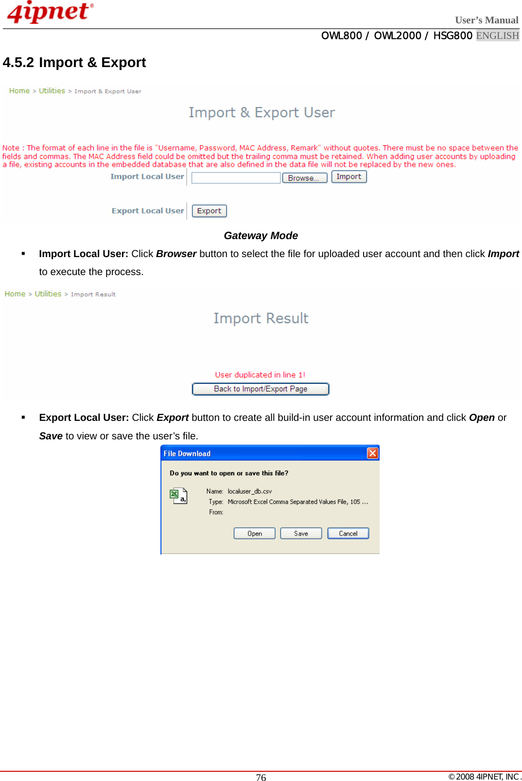
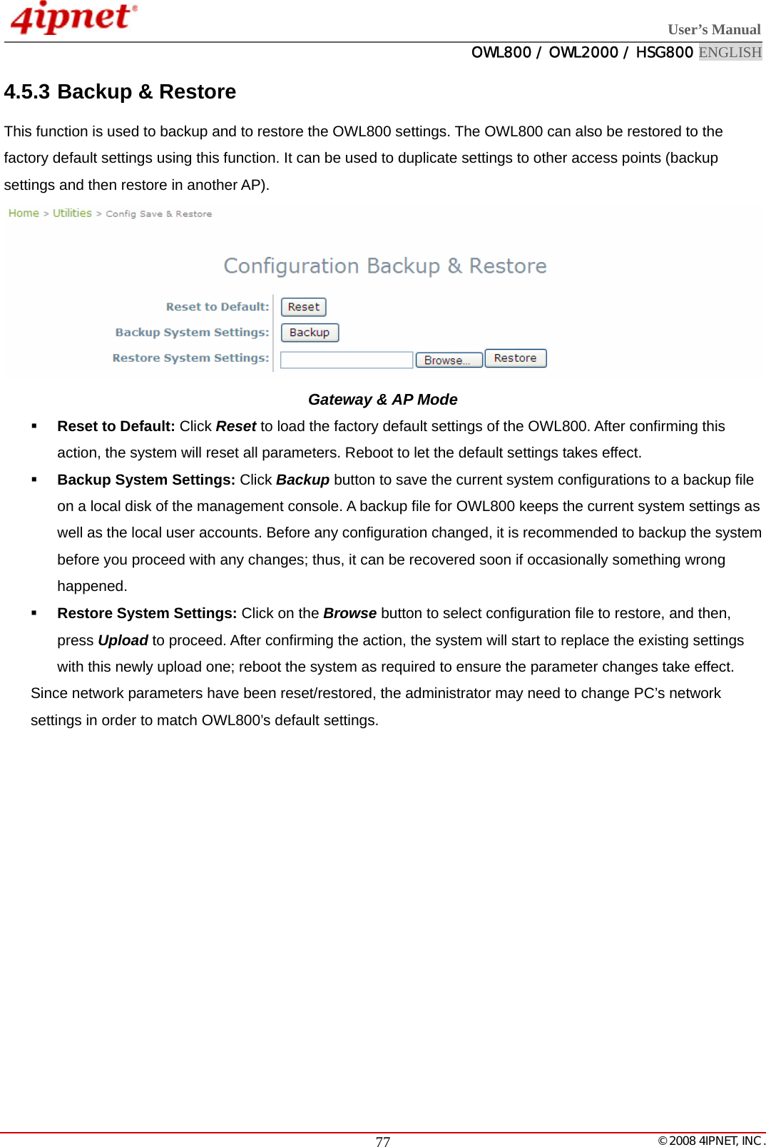
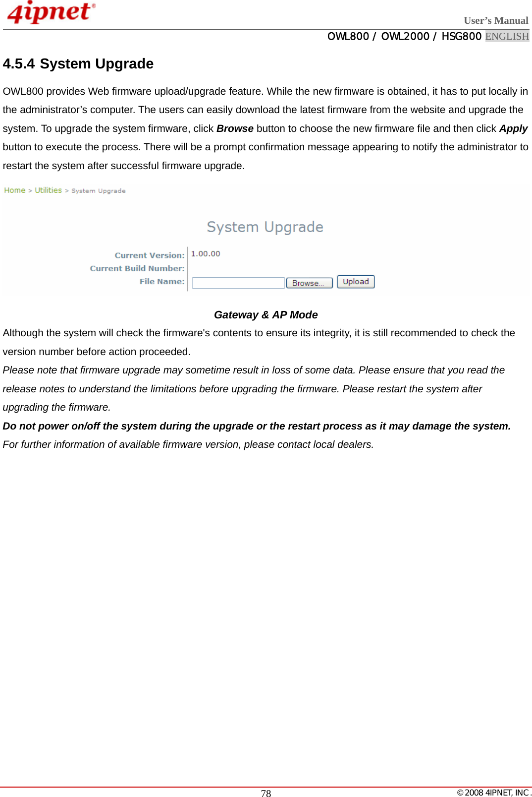
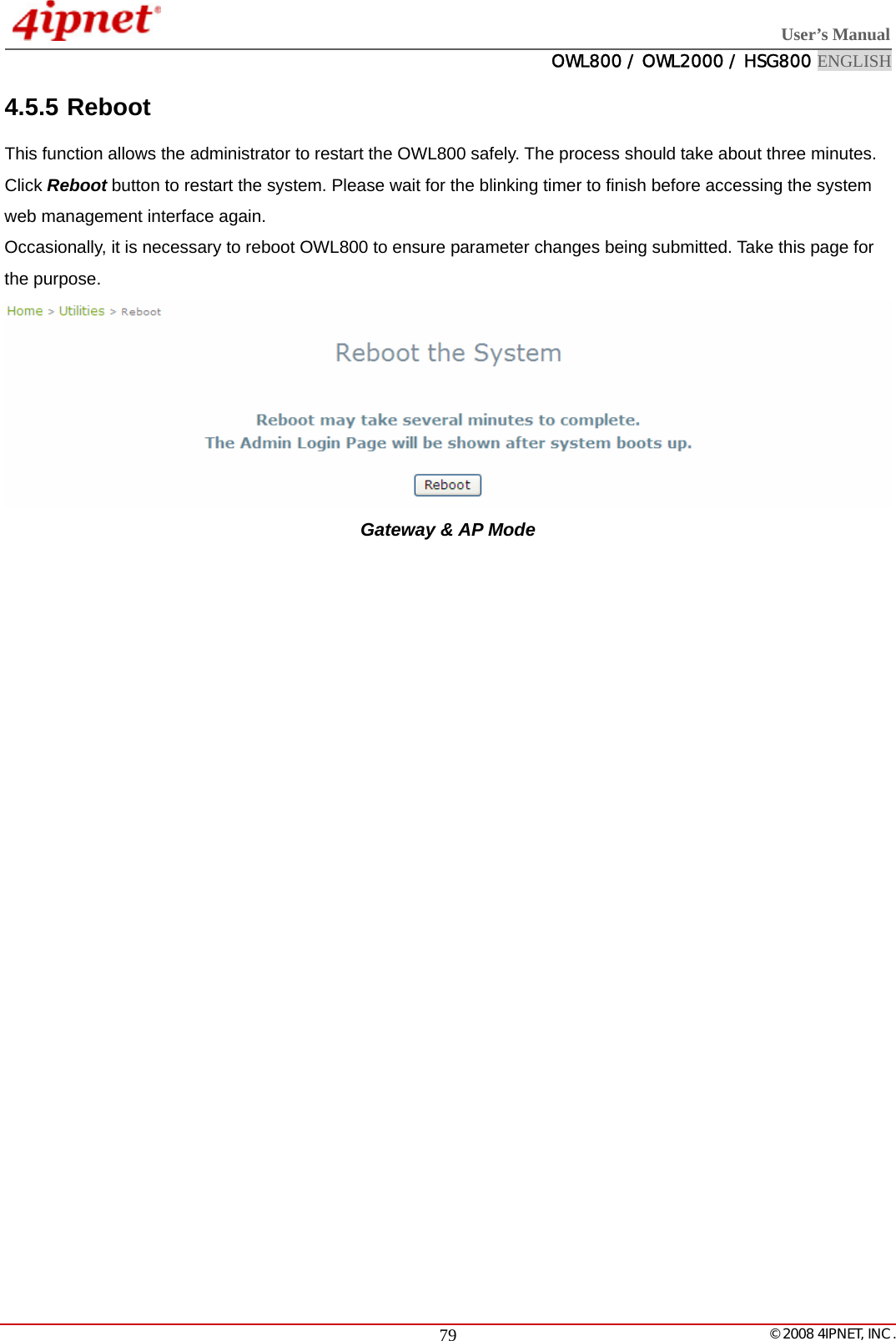
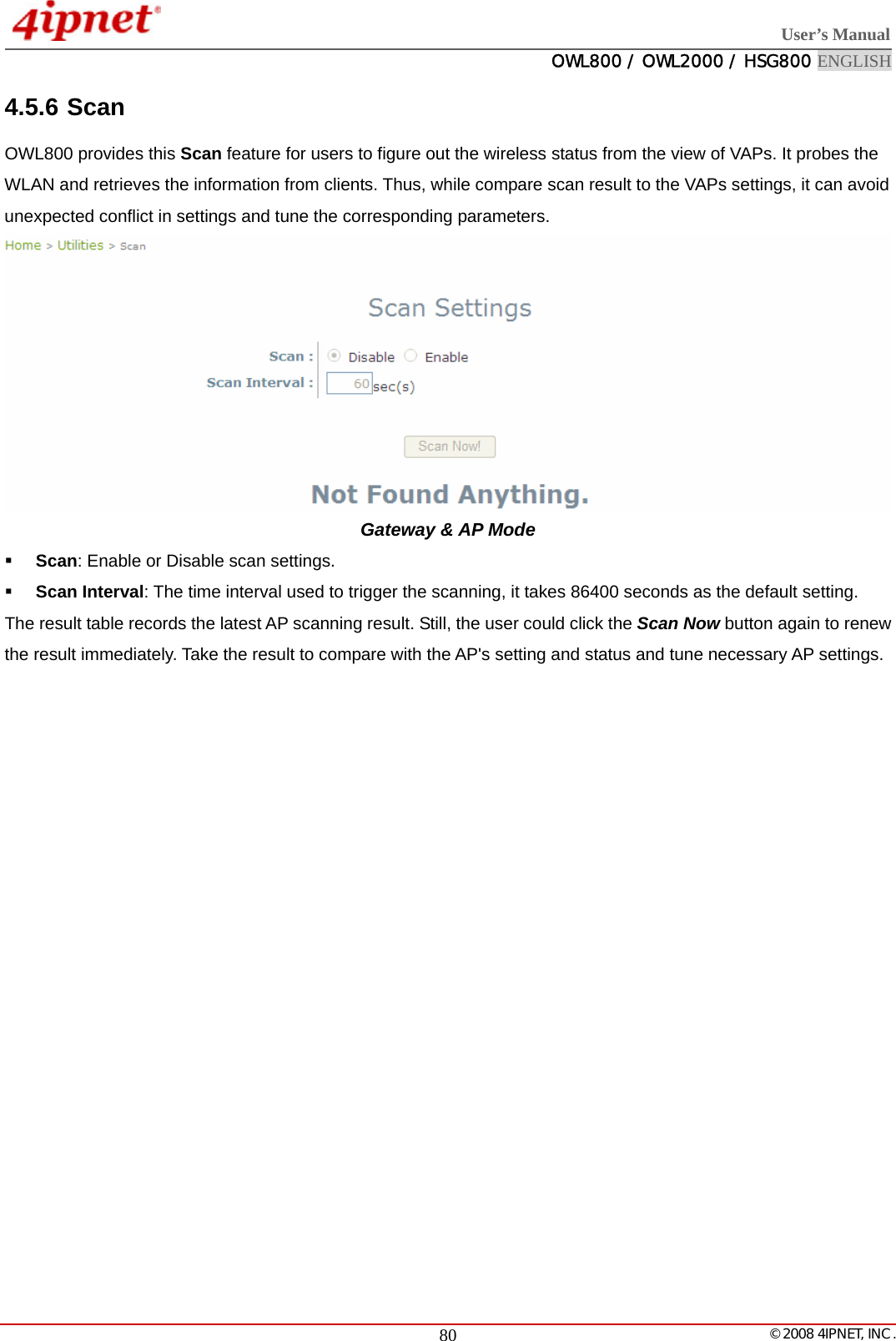
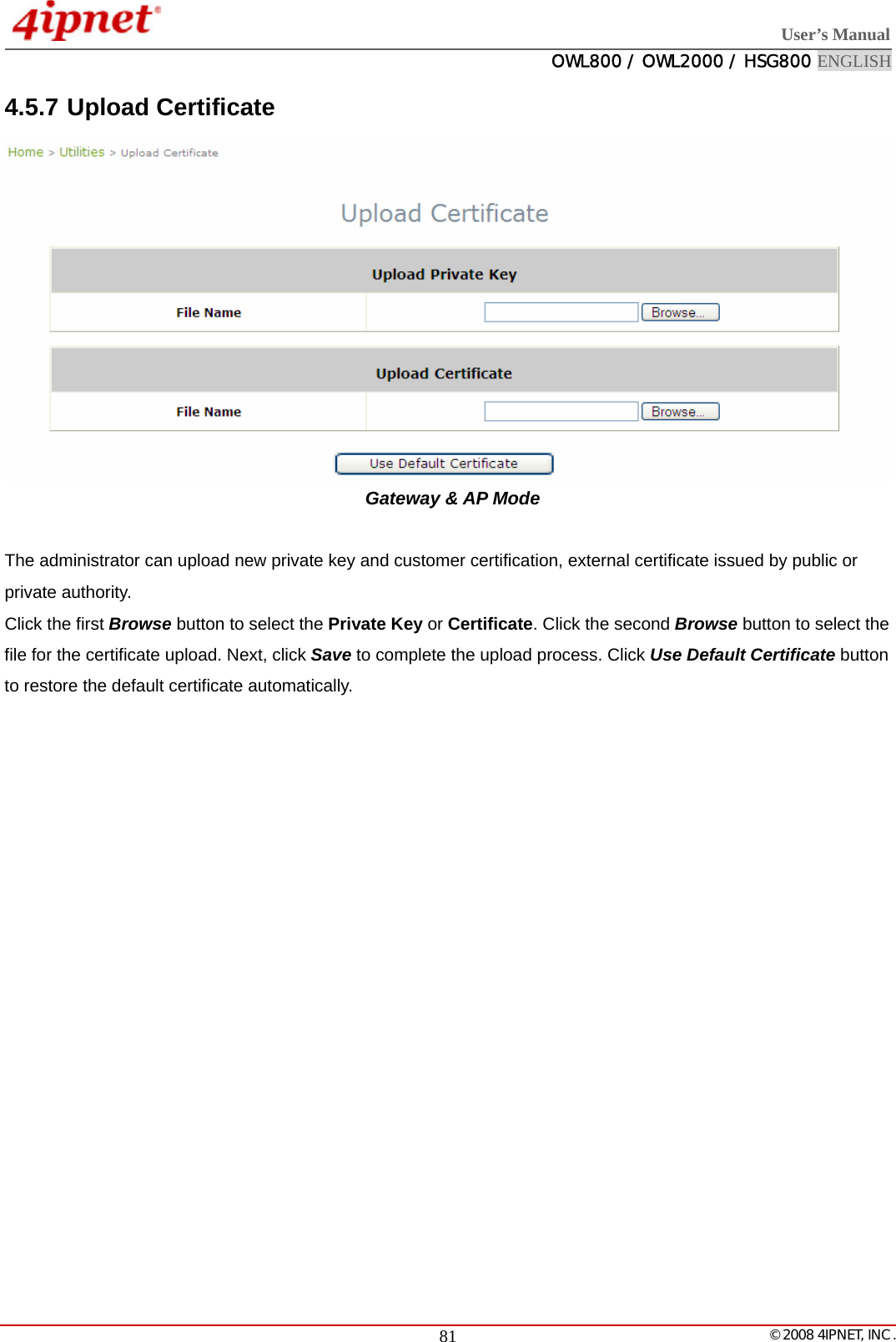
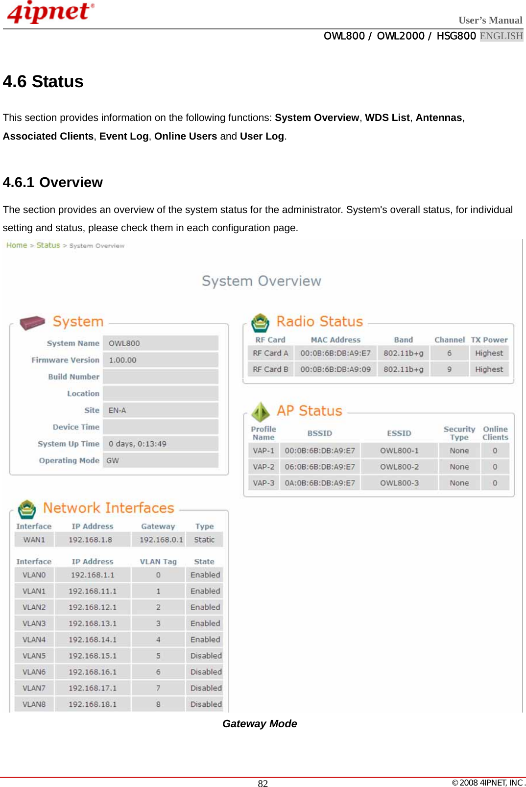
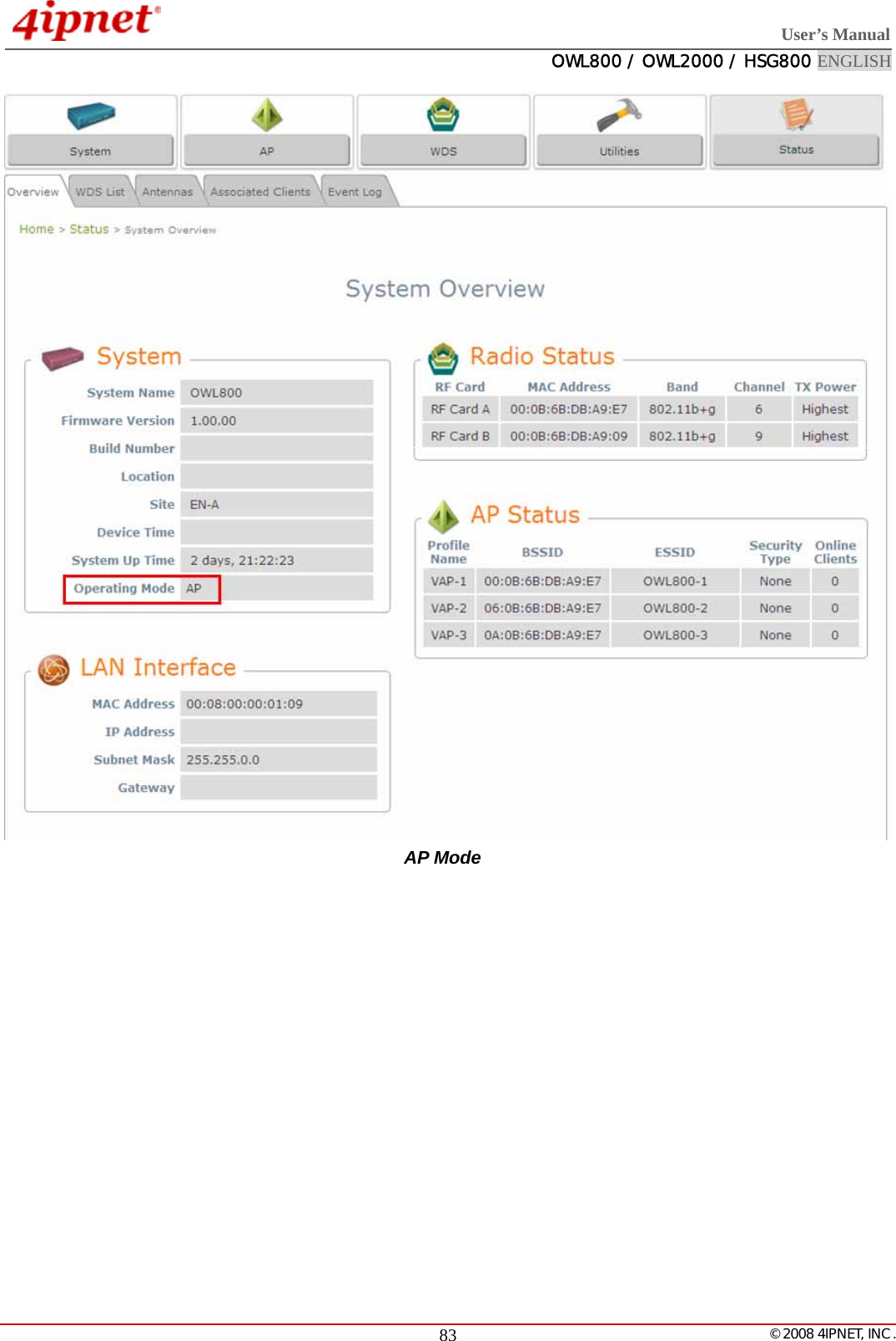
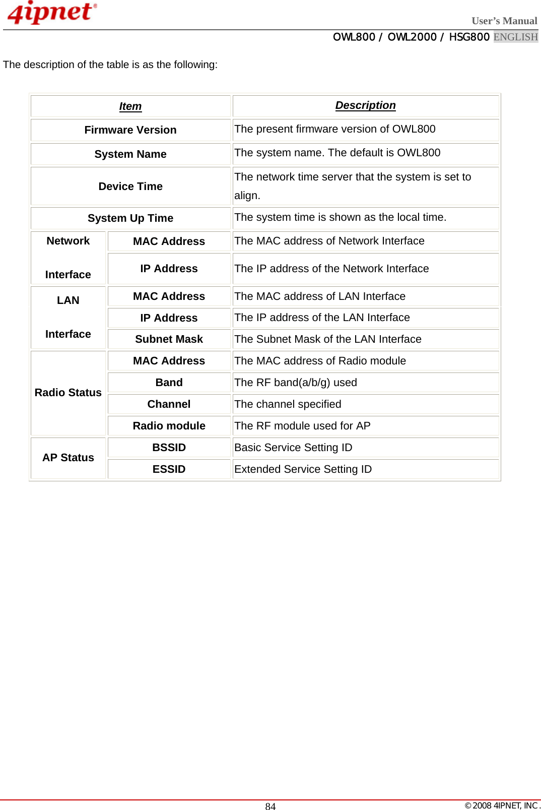
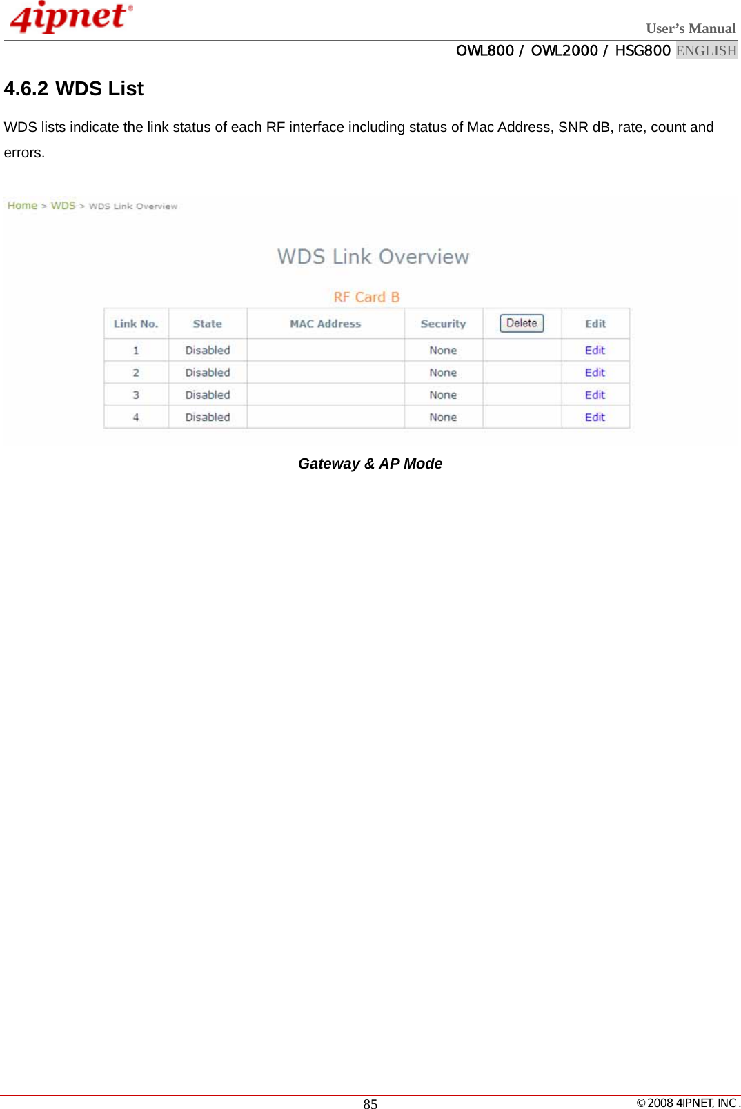
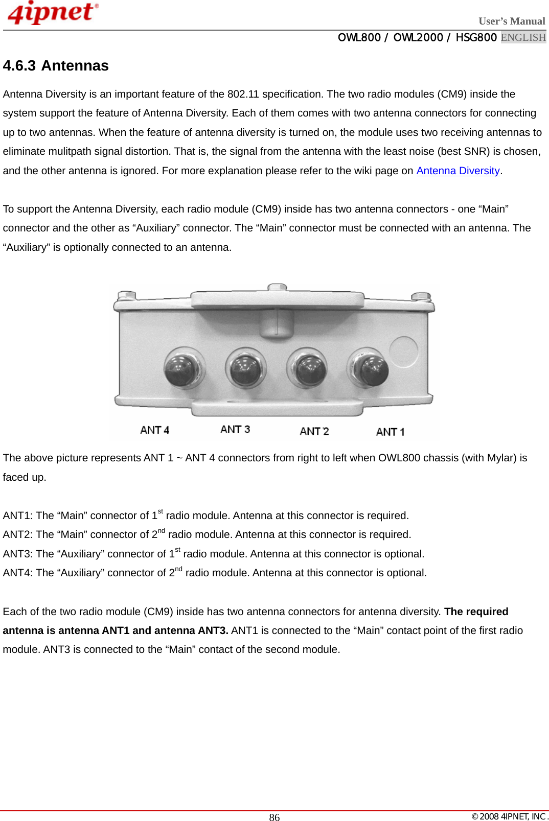
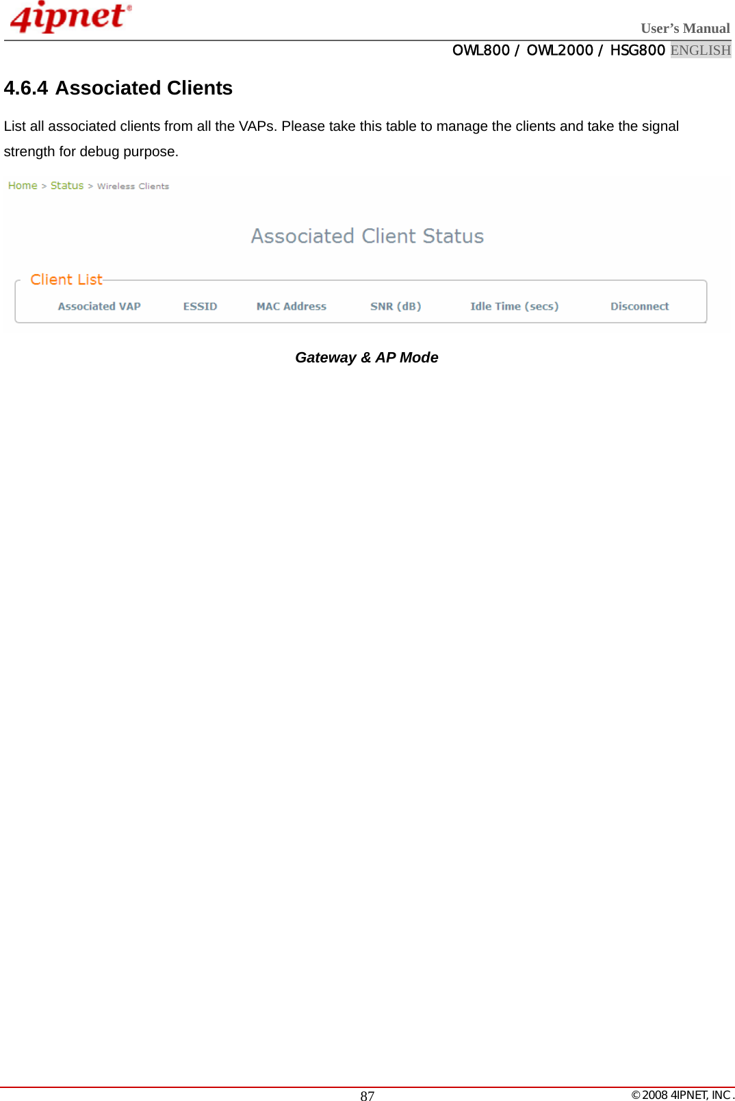
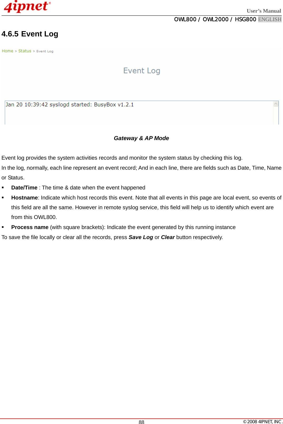
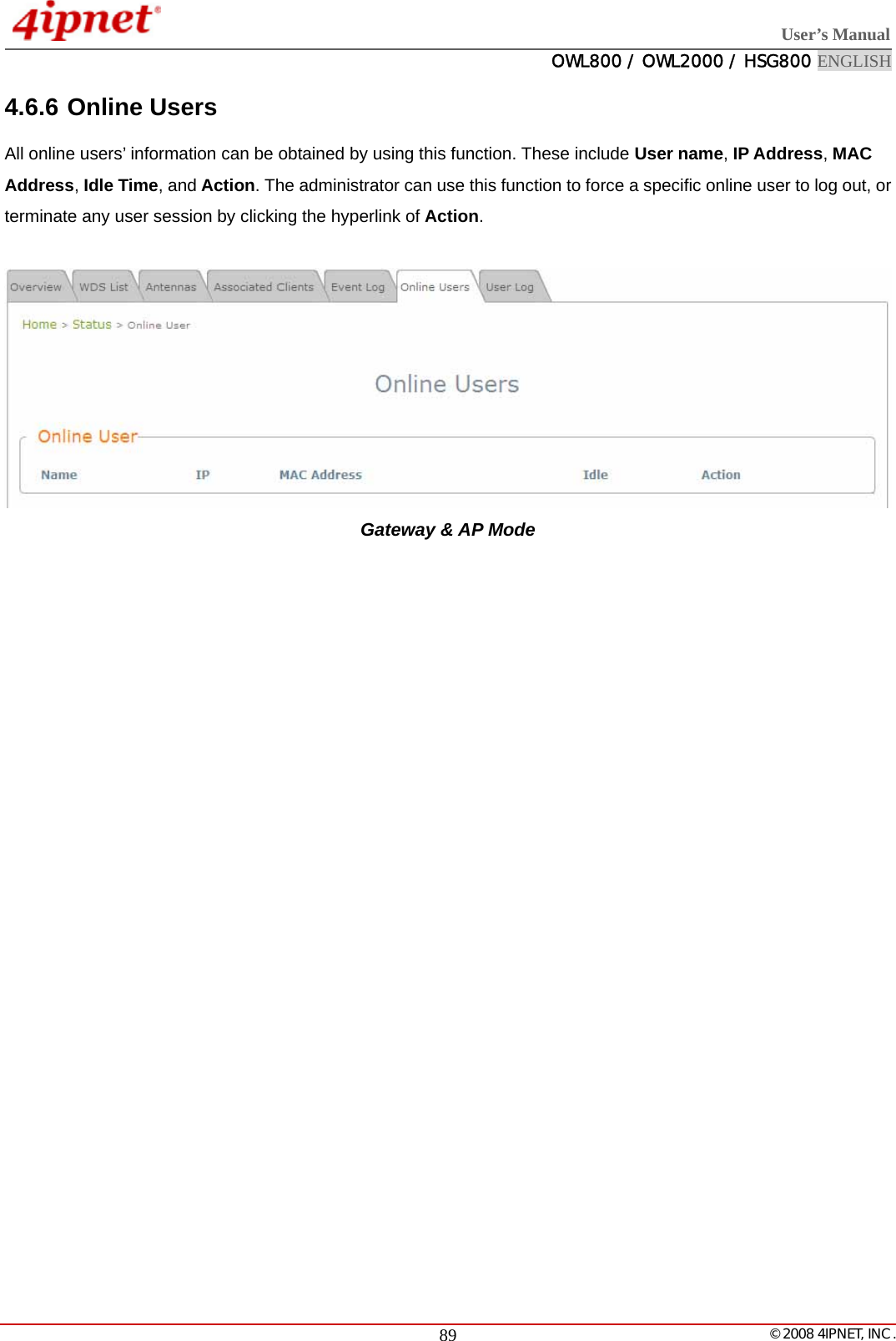
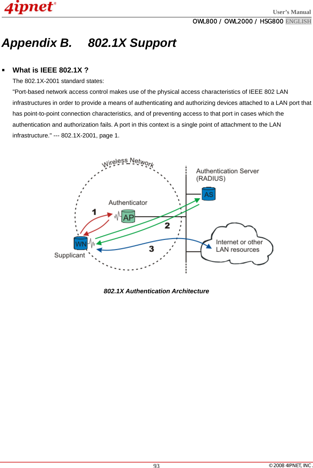
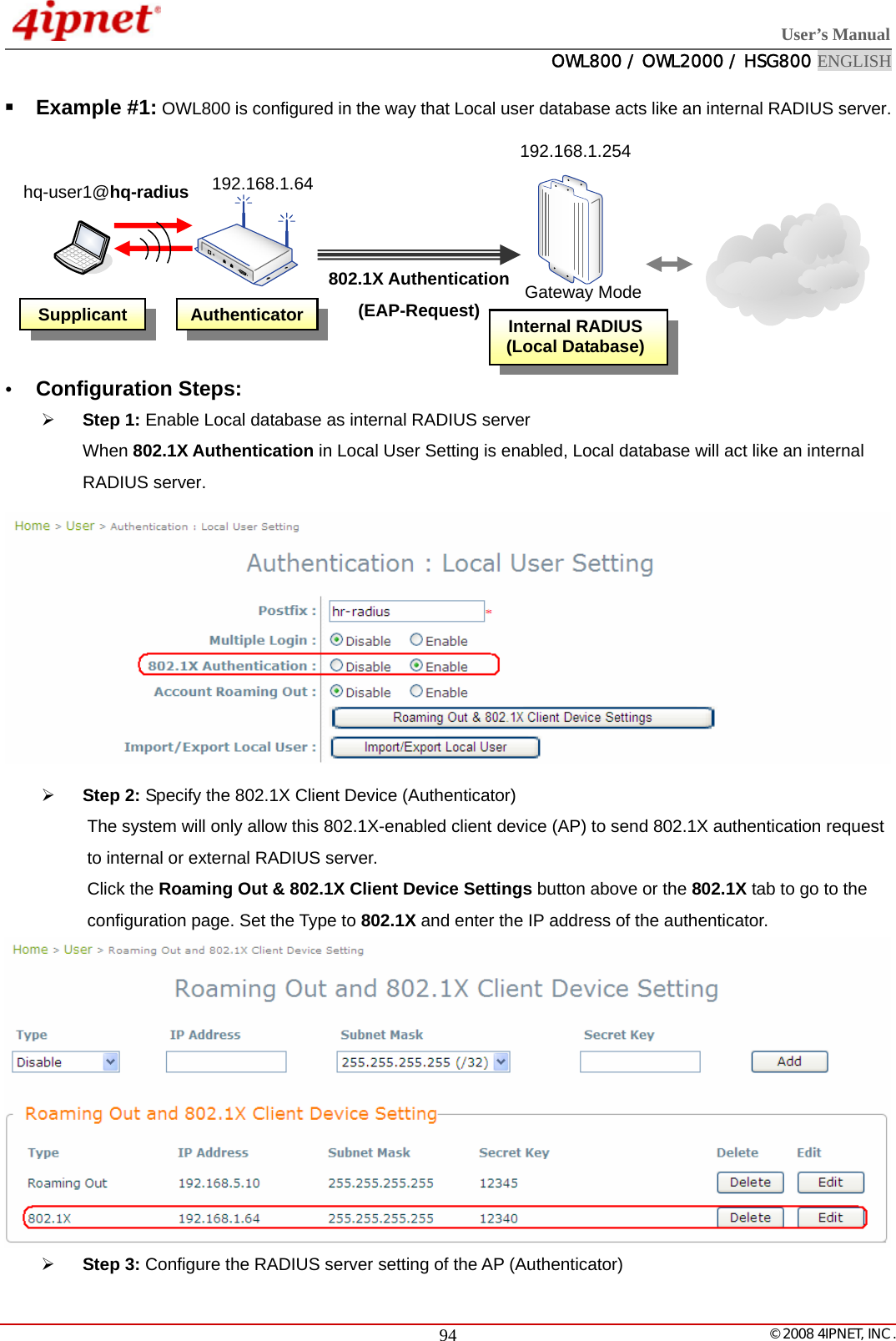
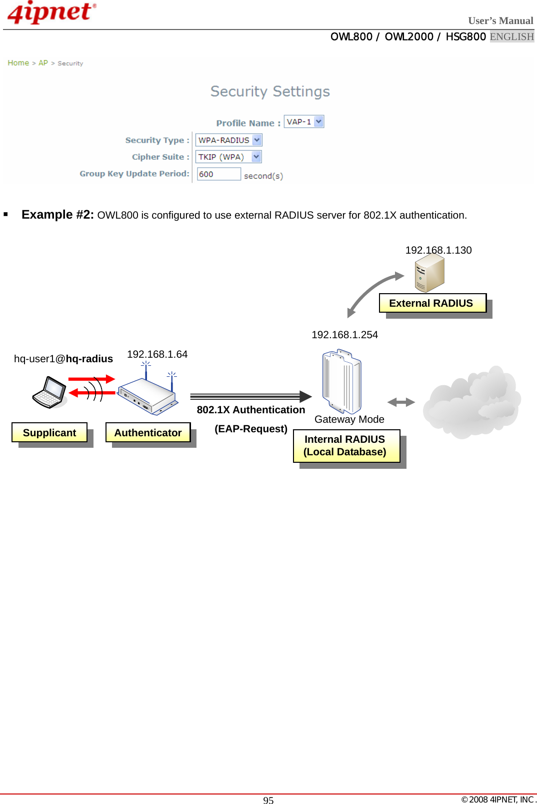
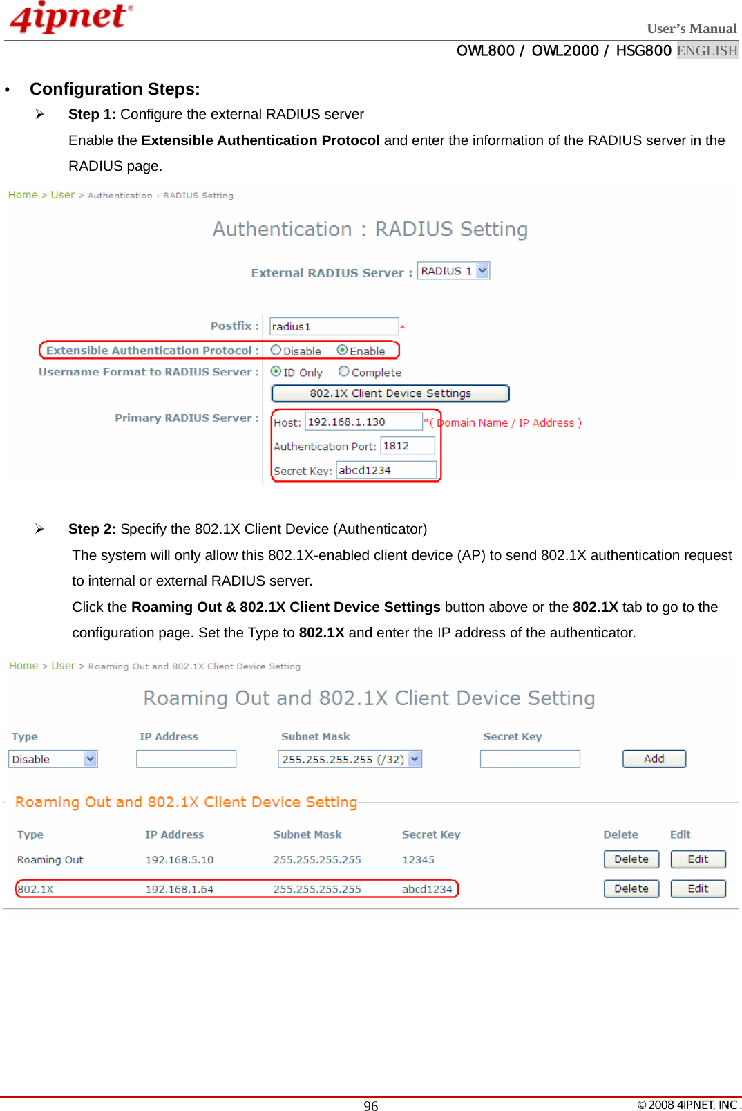
![User’s Manual OWL800 / OWL2000 / HSG800 ENGLISH © 2008 4IPNET, INC. 92¾ The following table shows the fields of a session log record. Field Description Date and Time The date and time that the session is established Session Type [New]: This is the newly established session. [Blocked]: This session is blocked by a Firewall rule. Username The account name (with postfix) of the user; It shows “N.A.” if the user or device does not need to log in with a username. For example, the user or device is on a non-authenticated port or on the privileged MAC/IP list. Note: Only 31 characters are available for the combination of Session Type plus Username. Please change the account name accordingly, if the name is not identifiable in the record. Protocol The communication protocol of session: TCP or UDP MAC The MAC address of the client SIP The source IP address of the client SPort The source port number of the client DIP The destination IP address of the client DPort The destination port number of the client ¾ The following table shows an example of the session log data. Aug 30 12:35:05 2007 [New]user1@local TCP MAC=00:09:6b:cd:83:8c SIP=10.1.1.37 SPort=1626 DIP=203.125.164.132 DPort=80 Aug 30 12:35:05 2007 [New]user1@local TCP MAC=00:09:6b:cd:83:8c SIP=10.1.1.37 SPort=1627 DIP=203.125.164.132 DPort=80 Aug 30 12:35:06 2007 [New]user1@local TCP MAC=00:09:6b:cd:83:8c SIP=10.1.1.37 SPort=1628 DIP=203.125.164.142 DPort=80 Aug 30 12:35:06 2007 [New]user1@local TCP MAC=00:09:6b:cd:83:8c SIP=10.1.1.37 SPort=1629 DIP=203.125.164.142 DPort=80 Aug 30 12:35:07 2007 [New]user1@local TCP MAC=00:09:6b:cd:83:8c SIP=10.1.1.37 SPort=1630 DIP=67.18.163.154 DPort=80 Aug 30 12:35:09 2007 [New]user1@local TCP MAC=00:09:6b:cd:83:8c SIP=10.1.1.37 SPort=1631 DIP=202.43.195.52 DPort=80 Aug 30 12:35:10 2007 [New]user1@local TCP MAC=00:09:6b:cd:83:8c SIP=10.1.1.37 SPort=1632 DIP=203.84.196.242 DPort=80](https://usermanual.wiki/4IPNET/090001/User-Guide-1118677-Page-101.png)