4IPNET 130002 Enterprise Access Point User Manual
4IPNET, INC. Enterprise Access Point Users Manual
4IPNET >
Users Manual
EAP210 or OWL530
Handbook

Quick Installation Guide
EAP210 or OWL530 Enterprise Access Point ENGLISH
Copyright © 4IPNET, INC. All rights reserved. i
Copyright Notice
This document is protected by USA copyright laws and other laws. Besides,
the document is the property of 4IPNET, INC. You may not copy, reproduce,
distribute, publish, display, perform, or modify any part of this publication in
any form or by any means without prior written permission from 4IPNET, INC.
You may not alter or remove any copyright or other notice from copies of
the content. All other brand and product names are claimed or registered
marks of their respective companies or organizations.
All rights reserved.
To download up-to-date version, please visit www.4ipnet.com.

Quick Installation Guide
EAP210 or OWL530 Enterprise Access Point ENGLISH
Copyright © 4IPNET, INC. All rights reserved. ii
FCC CAUTION
This equipment has been tested and proven to comply with the limits for a class B digital device,
pursuant to part 15 of the FCC Rules. These limits are designed to provide reasonable protection
against harmful interference in a residential installation. This equipment generates uses and can
radiate radio frequency energy and, if not installed and used in accordance with the instructions, may
cause harmful interference to radio communications. However, there is no guarantee that
interference will not occur in a particular installation. If this equipment does cause harmful
interference to radio or television reception, which can be determined by turning the equipment off
and on, the user is encouraged to try to correct the interference by one or more of the following
measures:
---Reorient or relocate the receiving antenna.
---Increase the separation between the equipment and receiver.
---Connect the equipment into an outlet on a circuit different from that to which the receiver is
connected.
---Consult the dealer or an experienced radio/TV technician for help.
The device contains a low power transmitter which will send out Radio Frequency (RF) signal when
transmitting. This equipment complies with FCC RF radiation exposure limits set forth for an
uncontrolled environment. This equipment should be installed and operated with a minimum distance of
20 centimeters between the radiator and your body.
This device complies with Part 15 of the FCC Rules. Operation is subject to the following two conditions:
(1) This device may not cause harmful interference, and (2) this device must accept any interference
received, including interference that may cause undesired operation.
FCC Caution: Any changes or modifications not expressly approved by the party responsible for
compliance could void the user's authority to operate this equipment.
This transmitter must not be co-located or operating in conjunction with any other antenna or transmitter.
Operations in the 5.15-5.25GHz band are restricted to indoor usage only.

Quick Installation Guide
EAP210 or OWL530 Enterprise Access Point ENGLISH
Copyright © 4IPNET, INC. All rights reserved. iii
Professional installation instruction
1. Installation personal
4ipnet OWL530 is designed for specific application and needs to be installed by a qualified
personal who has RF and related rule knowledge. The general user shall not attempt to install or
change the setting.
2. Installation location
4ipnet OWL530 shall be installed at a location where the radiating antenna can be kept 20 cm
from nearby person in normal operation condition to meet regulatory RF exposure requirement.
3. External antenna
Use only the antennas which have been approved by the applicant. The non-approved antenna(s)
may produce unwanted spurious or excessive RF transmitting power which may lead to the
violation of VZ9130002 limit and is prohibited.
4. Installation procedure
Please refer to user’s manual for the detail.
5. Warning
Please carefully select the installation position and make sure that the final output power does not
exceed the limit set force in relevant rules. The violation of the rule could lead to serious federal
penalty.

Quick Installation Guide
EAP210 or OWL530 Enterprise Access Point ENGLISH
Copyright © 4IPNET, INC. All rights reserved. iv
CE CAUTION
Declaration of Conformity with Regard to the 1999/5/EC (R&TTE Directive) for
European Community, Switzerland, Norway, Iceland, and Liechtenstein
Model: OWL530
For 2.4 GHz radios, the device has been tested and passed the requirements of the following standards,
and hence fulfills the EMC and safety requirements of R&TTE Directive within the CE marking
requirement.
• Radio: EN 300.328:
• Radio: EN 50392
• EMC: EN 301.489-1, EN 301.489-17,
• EMC: EN 55022 Class B, EN 55024:+ A1 + A2 including the followings:
EN 61000-3-2, EN 61000-3-3.
EN 61000-4-2, EN 61000-4-3, EN 61000-4-4,
EN 61000-4-5, EN 61000-4-6, EN 61000-4-11
• Safety: EN 60950-1 + A11,
Caution:
This declaration is only valid for configurations (combinations of software, firmware, and hardware)
provided and supported by 4ipnet Inc. The use of software or firmware not provided and supported
by 4ipnet Inc. may result in the equipment no longer being compliant with the regulatory
requirements.
European standards dictate maximum radiated transmit power of 100mW EIRP and frequency range
2.400-2.4835 GHz. This equipment is intended to be used in all EU and EFTA countries. Outdoor use
may be restricted to certain frequencies and/or may require a license for operation. Contact your local
regulatory authority for compliance.
Taiwan NCC Statement
根據 NCC 低功率電波輻射性電機管理辦法 規定:
第十二條 經型式認證合格之低功率射頻電機,非經許可,公司、商號或使用者均不得擅自變更頻率、加大功率或
變更原設計之特性及功能。
第十四條
低功率射頻電機之使用不得影響飛航安全及干擾合法通信;經發現有干擾現象時應立即停用,並改善至
無干擾時方得繼續使用。
前項合法通信,指依電信法規定作業之無線電通信。
低功率射頻電機須忍受合法通信或工業、科學及醫療用電波輻射性電機設備之擾。
Quick Installation Guide
EAP210 or OWL530 Enterprise Access Point ENGLISH
- 1 -
Preface Package Contents
4ipnet EAP210 or OWL530 is a high-end
802.11a/b/g/n 2.4GHz/ 5GHz MIMO Selectable Dual
Band Access Point (AP) designed to maximize
deployment flexibility and feasibility for IT
administrators.
The difference of EAP210 and OWL530 are the
mounting method. EAP210 is a desktop device
while OWL530 is designed to be pole-mount.
Complying with the latest industrial wireless security
standards that are required in the tightly secured
enterprise network environments, the AP makes the
wireless communication fast, secure and easy. It
supports business-grade secure encryption -
802.1X and Wi-Fi Protected Access (WPA and
WPA2) ; by pushing a purposely built button, the
4ipWES (Press-n-Connect) feature makes it easy
to bridge wireless links of multiple OWL530s for
forming a wider wireless network coverage.
EAP210 or OWL530 also features multiple ESSIDs
with VLAN tags and multiple Virtual APs; great for
enterprise applications, such as separating traffic
from different departments using different ESSIDs.
The PoE LAN port is able to receive power from
Power over Ethernet (PoE) sourcing devices. Its
metal case is IP68, which means that the is well
suited to WLAN deployment in industrial
environments.
This Quick Installation Guide provides instructions
and reference materials to get you started with
4ipnet EAP210 or OWL530.
1. 4ipnet OWL530 x 1 or EAP210 x 1
2. Quick Installation Guide (QIG) x 1
3. CD-ROM
(with User’s Manual and QIG) x 1
4. AC-DC Adaptor ( EAP210 only)
5. Power Sourcing Equipment (PSE) with
AC cable x 1 (Optional)
6. Mounting Kit x 1 (OWL530 only)
7. Ground Cable x 1 (OWL530 only)
It is recommended to keep the original
packing material for possible future shipment
when repair or maintenance is required. Any
returned product should be packed in its
original packaging to prevent damage during
delivery.
Quick Installation Guide
EAP210 or OWL530 Enterprise Access Point ENGLISH
- 2 -
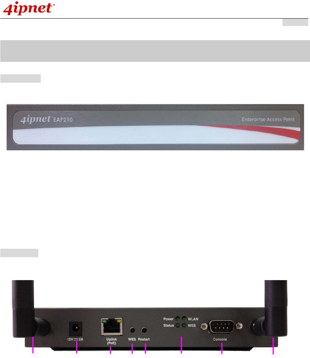
Hardware Overview of EAP210
Front Panel
Figure 1 EAP210 Front Panel
Rear Panel
1 (1) 2 3 71 (2)456
Figure 2 EAP210 Rear Panel

Quick Installation Guide
EAP210 or OWL530 Enterprise Access Point ENGLISH
- 3 -
1 Antenna
Connector
Reverse SMA connectors for attaching antennas.
1 (1) is the primary antenna connector and 1 (2) is the secondary.
Utilize both connectors for 802.11n MIMO optimized performance.
2 12V 2A Power Socket for the power adaptor.
3 Uplink Port The port for uplink connection to another gateway or device. PoE (802.3af/at) is
supported.
4 WES Button WDS Easy Setup. Press the button to build up a WDS link with another peer. 4 WDS
links can be set up.
5 Restart Button Press to restart the system
6 LED Indicators Power On indicates power on.
Status On indicates the system is ready.
WLAN On indicates wireless network interface is ready for service.
WES For indicating WDS connection status.
Master (Press for more than 3
seconds)
Slave (Press once and then
release right away)
WES Start LED (Green) OFF and then
BLINKING SLOWLY
LED (Green) BLINKS
SLOWLY
WES Negotiate BLINKING SLOWLY
(Green)
BLINKING RAPIDLY
(Green)
WES Success LED (Green) ON LED (Green) ON
WES Fail/Timeout LED (Green) OFF LED (Green) OFF
7 Console Port To access EAP210 via the console interface
Right-Side Panel
On the right side of the panel there is a Kensington slot. Admin can also fill it with a rubber plug.
Quick Installation Guide
EAP210 or OWL530 Enterprise Access Point ENGLISH
Copyright © 4IPNET, INC. All rights reserved.
- 4 -
H
ardware Overview
of OWL530
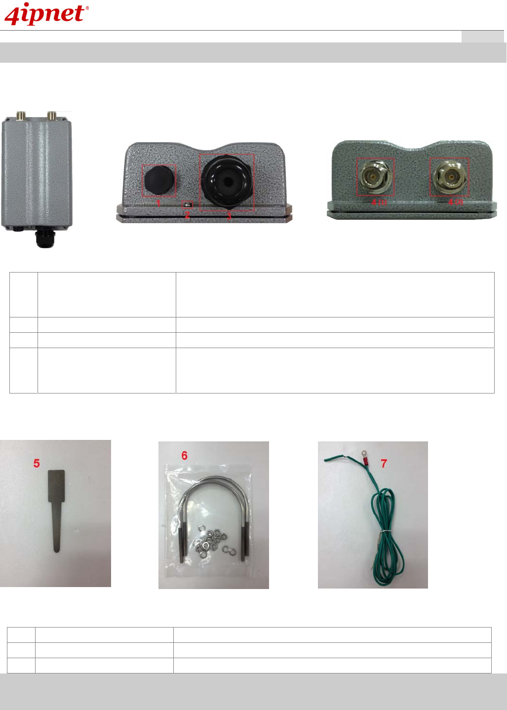
OWL530
1 Ventilation Valve Due to extreme weather conditions, water vapor in the OWL530
may condense. The valve allows ventilation to prevent moisture
buildup within the OWL530.
2 Ground Connector For connecting the ground wire.
3 PoE Connector For connecting to the Power Sourcing Equipment (PSE).
4 N-type Connector x 2 For connecting to an antenna
4 (1) is the primary antenna connector and 4 (2) is the secondary.
Utilize both connectors for 802.11n MIMO optimized performance.
Parts
H
ardware overview
of OWL530
OWL530
5 Detachment Tool For detaching the RJ45 connector from the PoE Port
6 Pole Mount Kit Includes two U-shaped bolts, 8 hex nuts and 8 split washers
7 Ground Wire For ground connection as mentioned in 2
Quick Installation Guide
EAP210 or OWL530 Enterprise Access Point ENGLISH
Copyright © 4IPNET, INC. All rights reserved.
- 5 -
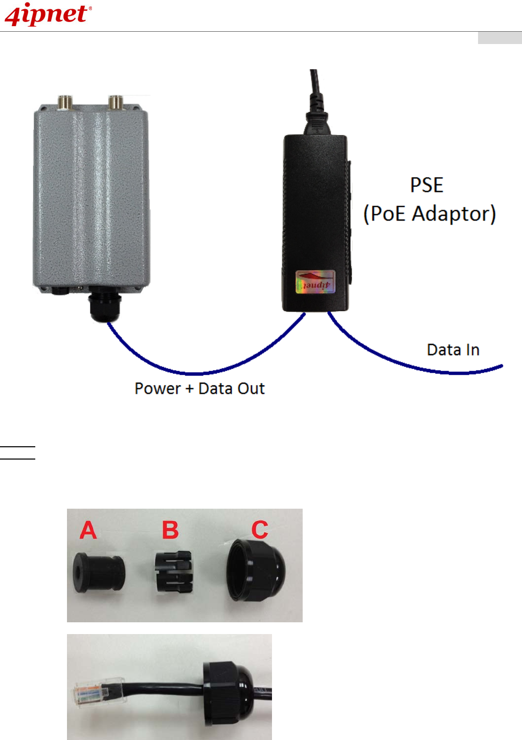
The following diagram is a basic network topology which can be used for testing and configuring the
OWL530.
Installation Steps:
Step 1. Connect two N-type antennas to the N-type connectors
Step 2. Connect one end of an Ethernet cable to the PSE (POWER & DATA OUT) to the PSE and one end
to the OWL530.
Inserting the RJ45 connector to the OWL530
- Unscrew the cap on the PoE Port (C)
- Insert the RJ45 cable through the outer opening of cap (C)
- Insert the RJ45 connector and wrap (A) around the Ethernet cable through the slit between the
connector and cap (C)
Quick Installation Guide
EAP210 or OWL530 Enterprise Access Point ENGLISH
Copyright © 4IPNET, INC. All rights reserved.
- 6 -
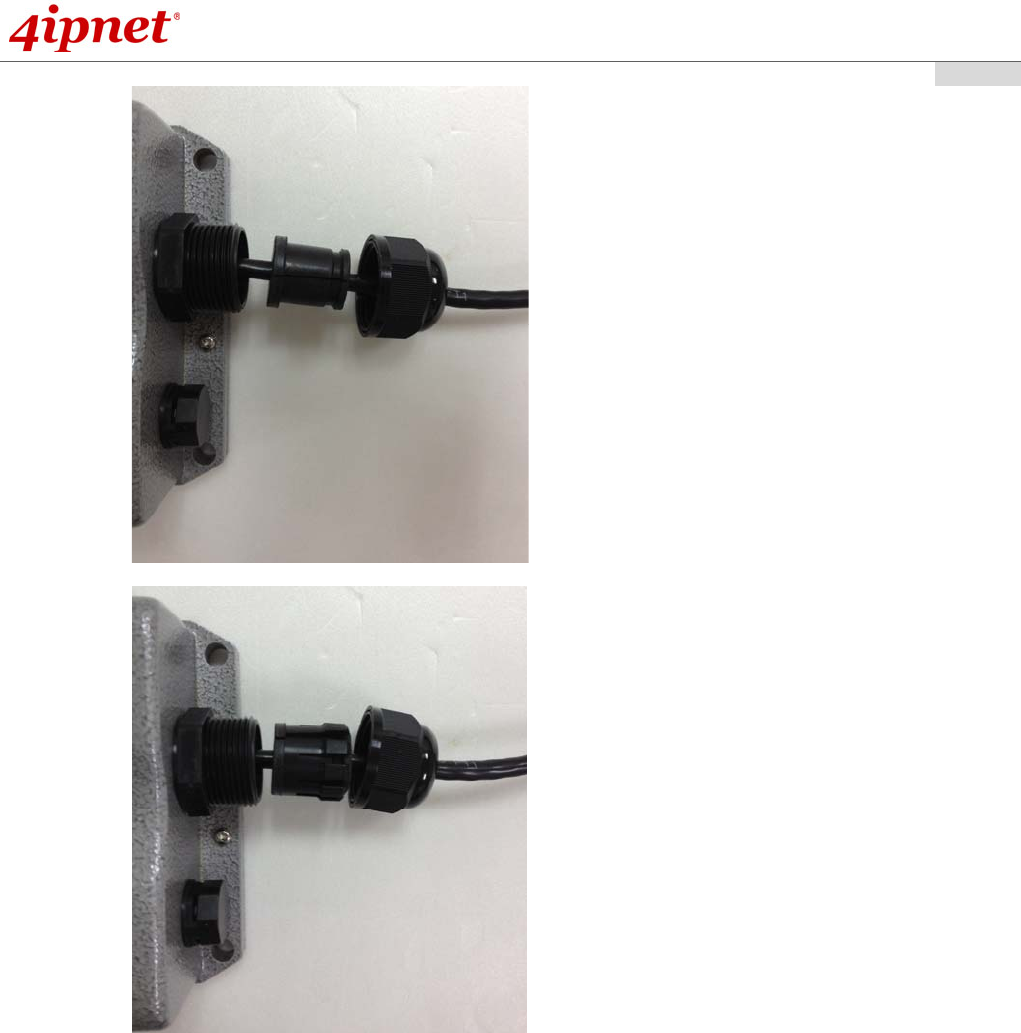
- Wrap (B) around (A) through the slit on (B)
- Insert Parts (A) and (B) together into the PoE Port
Quick Installation Guide
EAP210 or OWL530 Enterprise Access Point ENGLISH
Copyright © 4IPNET, INC. All rights reserved.
- 7 -
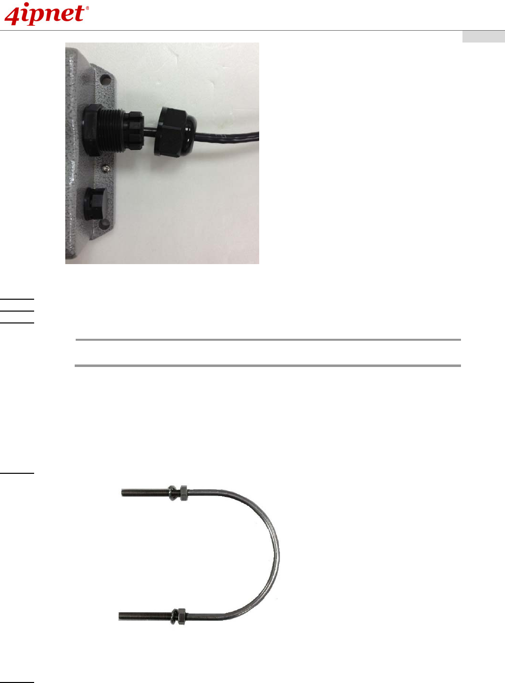
- Screw cap (C) onto the PoE Port
Step 3. Connect one end of another Ethernet cable to the PSE (Data Link) and the other end to a computer.
Step 4. Connect the power cord to the PSE.
Step 5. Power on the PSE in order to supply power to the OWL530.
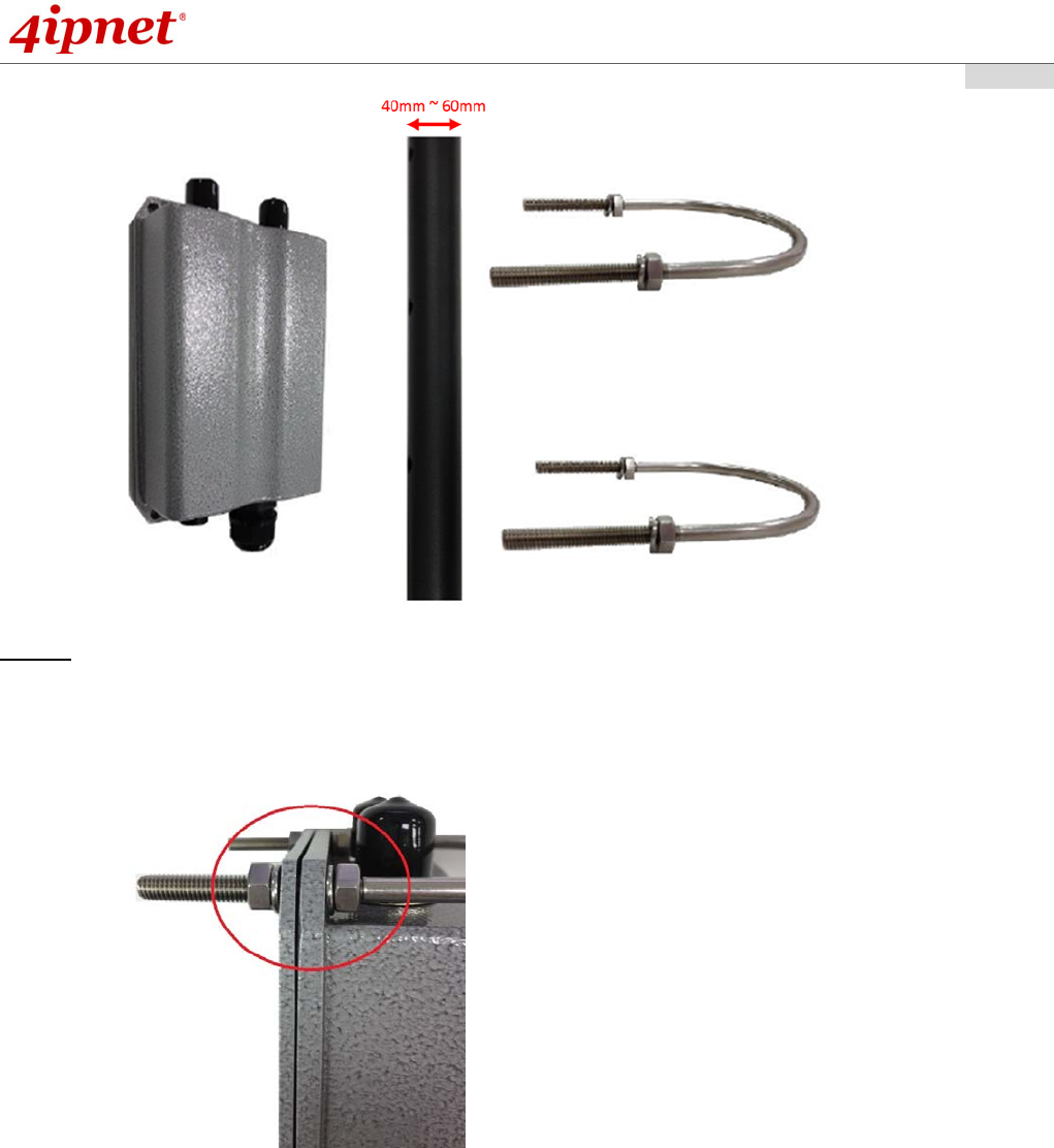
Mounting the OWL530
The diameter of poles mountable by the OWL530 mounting kit is from 40mm ~ 60mm
Step 1. Screw nuts onto the U-shaped bolts and insert bolts through the split washers.
Step 2. Align the front of OWL530 with the pole and insert the U-shaped bolts into the 4 holes on the corners
of the OWL530.
Note: Please do NOT remove or tamper with the ventilation valve as it has been
pre-installed and secured.
Quick Installation Guide
EAP210 or OWL530 Enterprise Access Point ENGLISH
Copyright © 4IPNET, INC. All rights reserved.
- 8 -
Step 3. Secure the OWL530 by screwing on the nuts after the inserting the washers for all four corners.
Quick Installation Guide
EAP210 or OWL530 Enterprise Access Point ENGLISH
Copyright © 4IPNET, INC. All rights reserved.
- 9 -
B
asic setting of EAP210 or OWL530
4ipnet EAP210 or OWL530 supports web-based configuration. It is required to follow the respective installation
procedures provided to properly set up the desired mode for this system.
Default IP Address of Web Management Interface:
The default IP address and Subnet Mask for the AP is as follows:
Mode AP Mode
IP Address 192.168.1.1
Subnet Mask 255.255.255.0
Step 1: IP Segment Setup for Administrator PC
Set a static IP address on the same subnet mask as the AP in TCP/IP of the administrator PC, such as the
following example. Do not duplicate the IP address used here with the IP address of the APor any other
devices within the same network.
>> Example of IP Segment:
The valid range of IP address is 1 ~ 254. However, 1 must be avoided as it is already used by the AP. Below
depicts an example of using 100 (the underlined value can be changed as desired).
IP Address: 192.168.1.100
Subnet Mask: 255.255.255.0
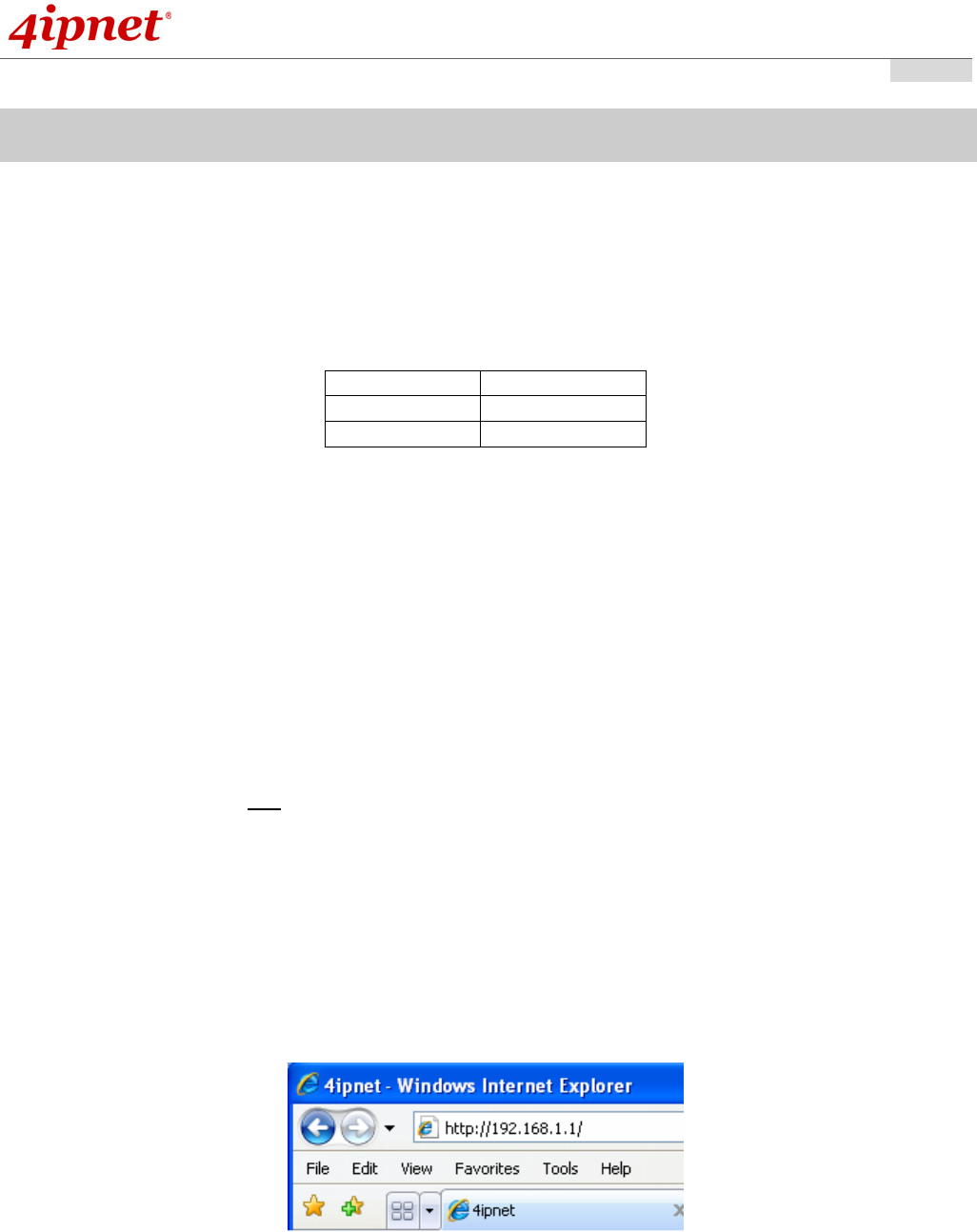
Step 2: Launch Web Browser
Launch a web browser to access the web management interface of AP mode by entering the default IP
address, http://192.168.1.1/, in the URL field, and then press Enter.
Quick Installation Guide
EAP210 or OWL530 Enterprise Access Point ENGLISH
Copyright © 4IPNET, INC. All rights reserved.
- 10 -
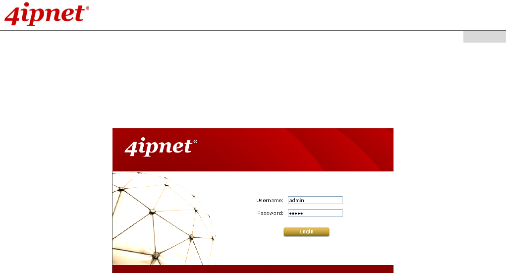
Step 3: System Login
The system manager Login Page will then appear.
Enter “admin” in the User name field and “admin” in the Password field, and then click Login to log in.
Quick Installation Guide
EAP210 or OWL530 Enterprise Access Point ENGLISH
Copyright © 4IPNET, INC. All rights reserved.
- 11 -
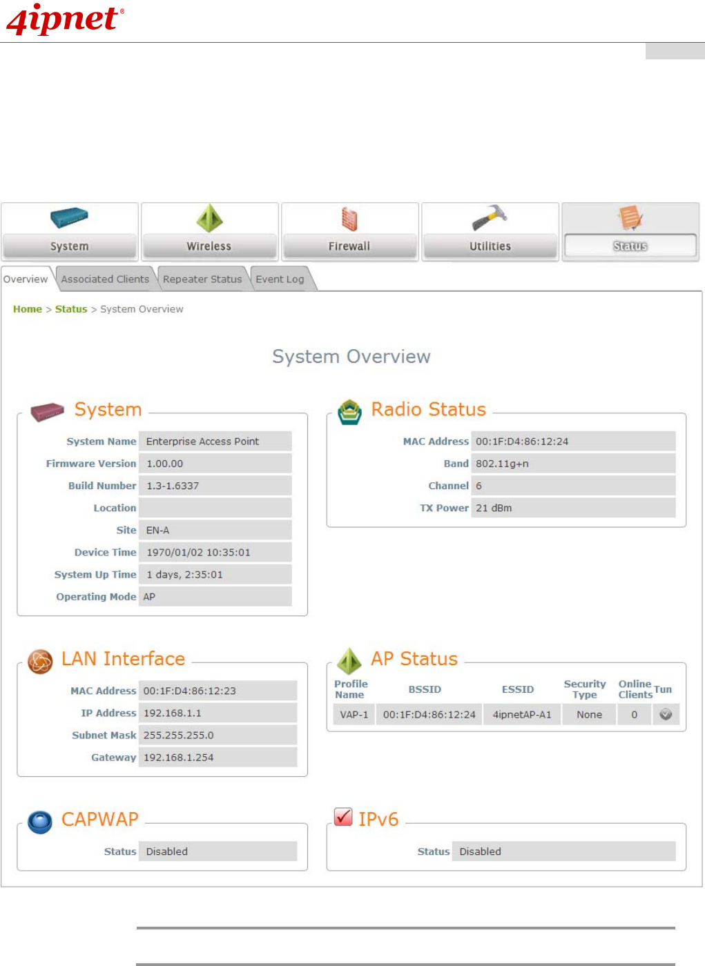
Step 4: Login Success
After a successful login to EAP210 or OWL530, a System Overview page of web management interface will
appear,
To logout, simply click on the Logout button at the upper right hand corner of the interface.
Note: AP mode is the default mode. The administrator must access the system via the AP
mode login page first before switching modes.
Quick Installation Guide
EAP210 or OWL530 Enterprise Access Point ENGLISH
Copyright © 4IPNET, INC. All rights reserved.
- 12 -
Common Settings
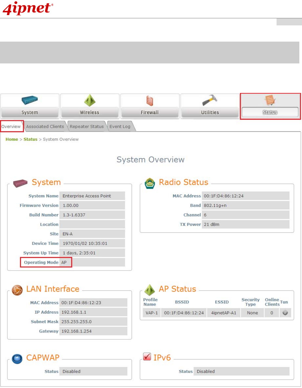
Step 1: Mode Confirmation
Ensure the Operating Mode is currently in AP mode.
Click on the Status button and then select the System Overview tab. The Operating Mode is at the
System section on the System Overview page.

Quick Installation Guide
EAP210 or OWL530 Enterprise Access Point ENGLISH
Copyright © 4IPNET, INC. All rights reserved.
- 13 -
Quick Installation Guide
EAP210 or OWL530 Enterprise Access Point ENGLISH
Copyright © 4IPNET, INC. All rights reserved.
- 14 -
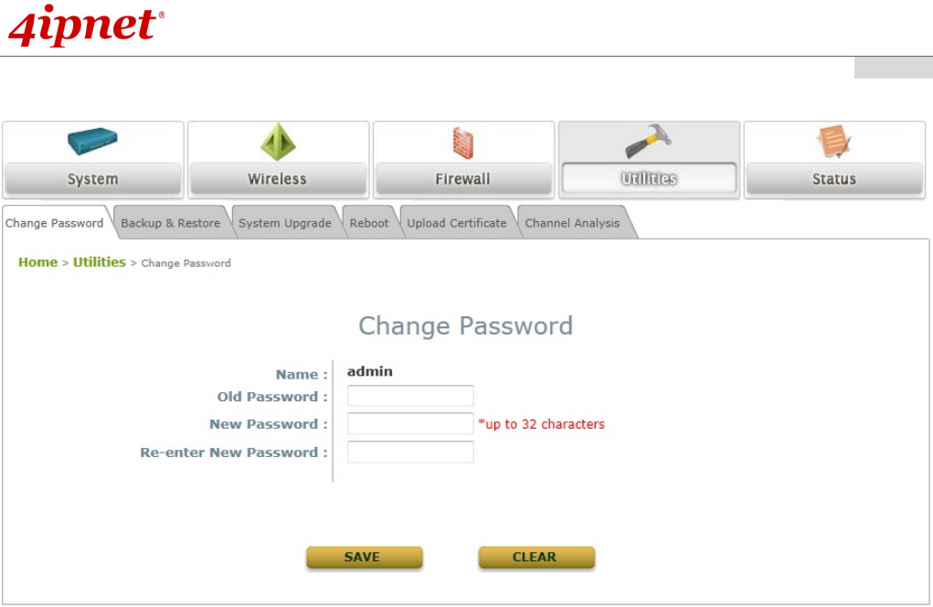
Step 2: Change Password
Click on the Utilities button and then select the Password tab.
Enter a new password in the New Password field and retype it in the Re-enter New Password field.
Click SAVE to save the changes.
Quick Installation Guide
EAP210 or OWL530 Enterprise Access Point ENGLISH
Copyright © 4IPNET, INC. All rights reserved.
- 15 -
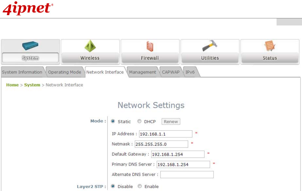
Step 3: Network Settings
【Example Settings】
Click on the System button and then select the Network Interface tab.
Click the Static radio button and enter the related information in the fields marked with red asterisks.
Click SAVE to save the settings.
Quick Installation Guide
EAP210 or OWL530 Enterprise Access Point ENGLISH
Copyright © 4IPNET, INC. All rights reserved.
- 16 -
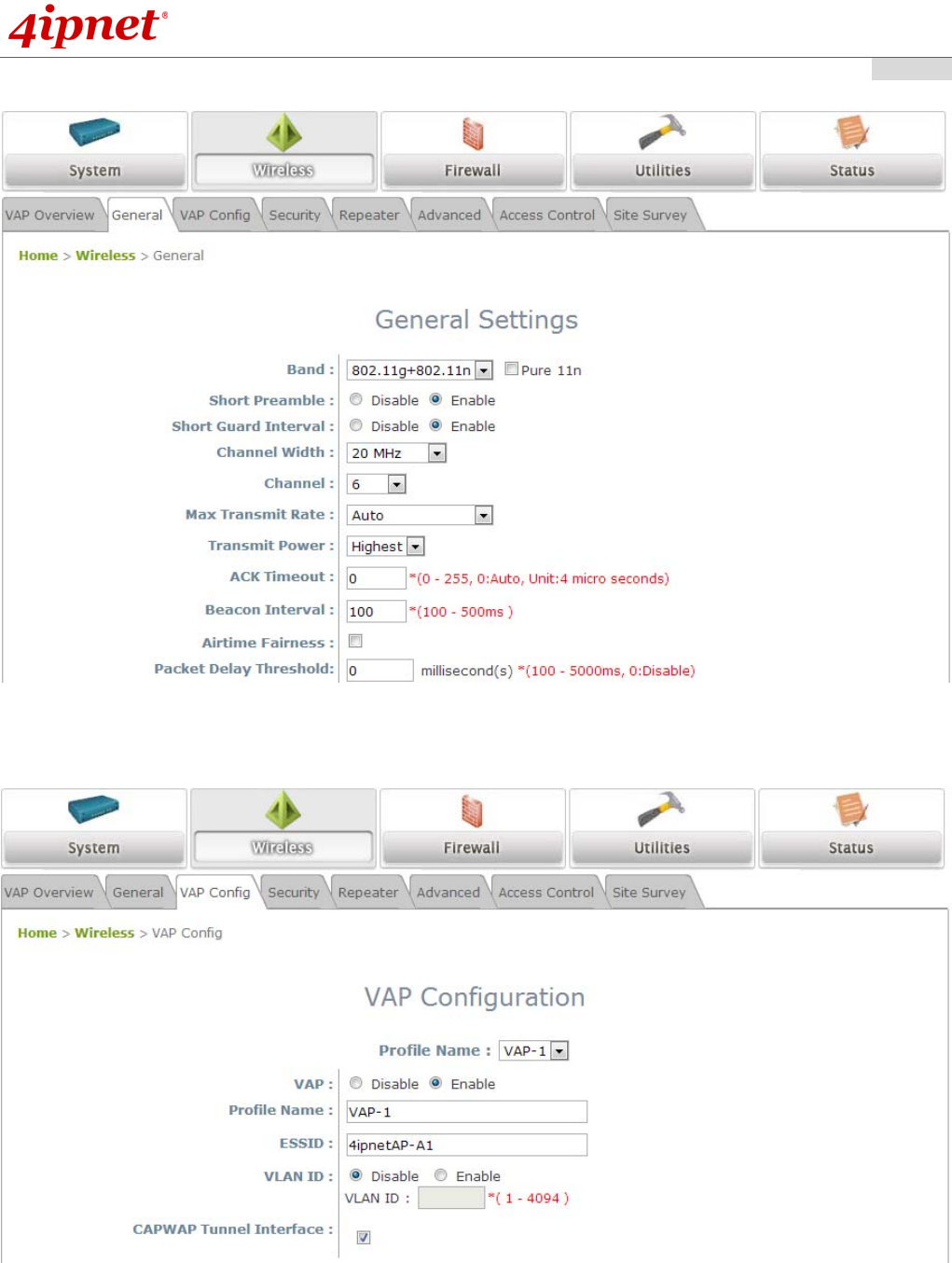
Step 4: SSID Settings
Click on the Wireless button and select the General tab.
Band: Select an appropriate band from the drop-down list box.
Click on the Wireless button and select the VAP Config tab.
ESSID: Enter respective ESSID for each VAP in the ESSID field or use the default. ESSID (Extended
Service Set Identifier) is a unique identifier used for networking devices to get associated with th AP.
Click SAVE to save the settings.
Quick Installation Guide
EAP210 or OWL530 Enterprise Access Point ENGLISH
Copyright © 4IPNET, INC. All rights reserved.
- 17 -
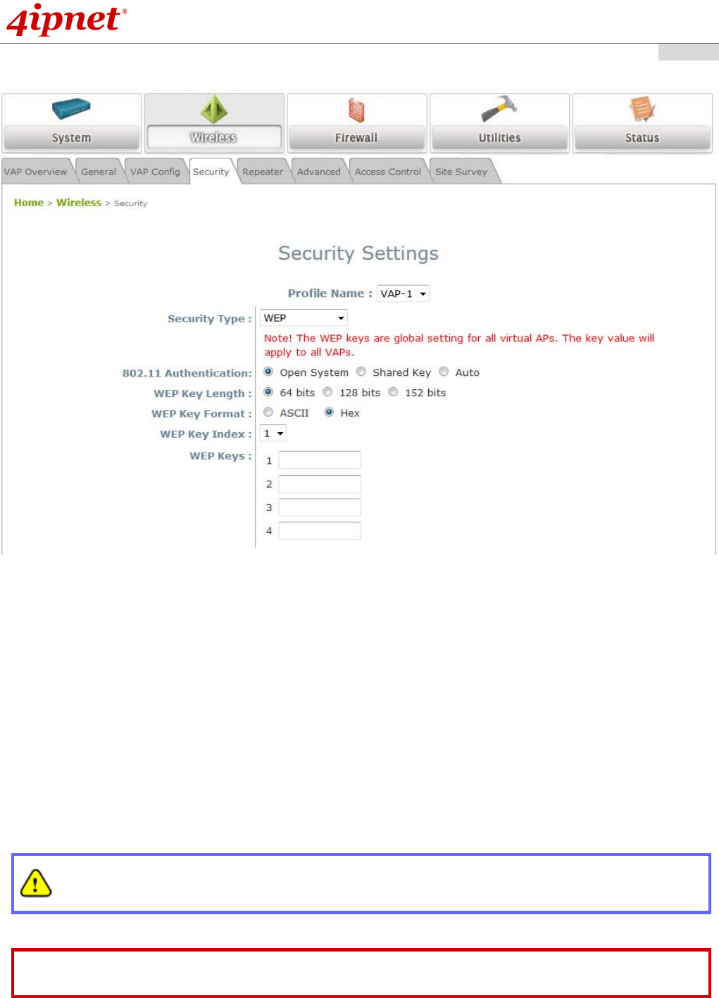
Step 5: Security Settings
Click on the Wireless button and then select the Security tab.
Select the desired VAP Profile and Security Type from the drop-down list boxes. The system supports
various WiFi standard security such as WEP, WPA Personal, WPA Enterprise, and 802.1X. The above
figure depicts an example of selecting VAP-1 and WEP.
Enter the information required in the blank fields.
Click SAVE to save all settings configured so far; all updated settings will take effect upon reboot.
Congratulations!
The EAP210 or OWL530 is now successfully configured.
After OWL530's network configuration completes, please remember to change the IP Address of your
PC Connection Properties back to its original settings in order to ensure that your PC functions
properly in its real network environments.
It is strongly recommended to make a backup copy of configuration settings.
For further configuration and backup information, please refer to the User’s Manual.
P/N: V10020140626