4IPNET 140001 ENTERPRISE ACCESS POINT User Manual QIG
4IPNET, INC. ENTERPRISE ACCESS POINT QIG
4IPNET >
User Manual
EAP767 V1.00
Enterprise Access Point

Quick Installation Guide
EAP767 Enterprise Access Point ENGLISH
Copyright © 4IPNET, INC. All rights reserved.
i
Copyright Notice
This document is protected by USA copyright laws and other laws. Besides, the
document is the property of 4IPNET, INC. You may not copy, reproduce, distribute,
publish, display, perform, or modify any part of this publication in any form or by any
means without prior written permission from 4IPNET, INC. You may not alter or remove any
copyright or other notice from copies of the content. All other brand and product names
are claimed or registered marks of their respective companies or organizations.
All rights reserved.
To download up-to-date version, please visit www.4ipnet.com.

Quick Installation Guide
EAP767 Enterprise Access Point ENGLISH
Copyright © 4IPNET, INC. All rights reserved.
ii
FCC CAUTION
This device complies with Part 15 of the FCC Rules. Operation is subject to the following two
conditions: (1) This device may not cause harmful interference, and (2) this device must accept any
interference received, including interference that may cause undesired operation.
This equipment has been tested and proven to comply with the limits for a class B digital device,
pursuant to part 15 of the FCC Rules. These limits are designed to provide reasonable protection
against harmful interference in a residential installation. This equipment generates uses and can
radiate radio frequency energy and, if not installed and used in accordance with the instructions, may
cause harmful interference to radio communications. However, there is no guarantee that
interference will not occur in a particular installation. If this equipment does cause harmful
interference to radio or television reception, which can be determined by turning the equipment off
and on, the user is encouraged to try to correct the interference by one or more of the following
measures:
---Reorient or relocate the receiving antenna.
---Increase the separation between the equipment and receiver.
---Connect the equipment into an outlet on a circuit different from that to which the receiver is
connected.
---Consult the dealer or an experienced radio/TV technician for help.
The device contains a low power transmitter which will send out Radio Frequency (RF) signal when
transmitting. This equipment complies with FCC RF radiation exposure limits set forth for an uncontrolled
environment. This equipment should be installed and operated with a minimum distance of 20 centimeters
between the radiator and your body.
FCC Caution: Any changes or modifications not expressly approved by the party responsible for compliance
could void the user's authority to operate this equipment.
This transmitter must not be co-located or operating in conjunction with any other antenna or transmitter.
Operations in the 5.15-5.25GHz band are restricted to indoor usage only.

Quick Installation Guide
EAP767 Enterprise Access Point ENGLISH
Copyright © 4IPNET, INC. All rights reserved.
iii
CE CAUTION
Declaration of Conformity with Regard to the 1999/5/EC (R&TTE Directive) for
European Community, Switzerland, Norway, Iceland, and Liechtenstein
Model: EAP767
For 2.4 GHz radios, the device has been tested and passed the requirements of the following standards, and
hence fulfills the EMC and safety requirements of R&TTE Directive within the CE marking requirement.
• Radio: EN 300.328:
• EMC: EN 301.489-1, EN 301.489-17,
• EMC: EN 55022 Class B, EN 55024:+ A1 + A2 including the followings:
EN 61000-3-2, EN 61000-3-3.
EN 61000-4-2, EN 61000-4-3, EN 61000-4-4,
EN 61000-4-5, EN 61000-4-6, EN 61000-4-11
• Safety: EN 60950-1 + A11,
Caution:
This declaration is only valid for configurations (combinations of software, firmware, and hardware)
provided and supported by 4ipnet Inc. The use of software or firmware not provided and supported by
4ipnet Inc. may result in the equipment no longer being compliant with the regulatory requirements.
European standards dictate maximum radiated transmit power of 100mW EIRP and frequency range
2.400-2.4835 GHz. This equipment is intended to be used in all EU and EFTA countries. Outdoor use may be
restricted to certain frequencies and/or may require a license for operation. Contact your local regulatory
authority for compliance.
Taiwan NCC Statement
根據 NCC 低率電波輻射性電機管理辦法 規定:
第十二條
經型式認證合格之低率射頻電機,非經許可,公司商號或使用者均不得擅自變更頻率大率或
變更原設計之特性及能
第十四條
低率射頻電機之使用不得影響飛航安及干擾合法通信經發現有干擾現象時應立即停用,並改善至
無干擾時方得繼續使用
前項合法通信,指依電信法規定作業之無線電通信
低率射頻電機須忍受合法通信或工業科學及醫療用電波輻射性電機設備之擾
在5.25 ~ 5.35 秭赫頻帶操作之無線資訊傳輸設備,限於室使用

Quick Installation Guide
EAP767 Enterprise Access Point ENGLISH
Copyright © 4IPNET, INC. All rights reserved.
1
Preface
Package Contents
4ipnet EAP767 is a high-end, dual radio 802.11
b/g/n + ac MIMO Access Point (AP) with the best
performance for business and industrial applications
and is compliant with the latest industrial wireless
security standards that are required in the tightly
secured enterprise network environments.
EAP767 makes the wireless communication fast,
secure and easy. It supports business grade
security such as 802.1X, and Wi-Fi Protected
Access (WPA and WPA2). The EAP767 supports
multiple point-to-point wireless links to form wider
wireless network coverage.
EAP767 also features multiple ESSIDs with VLAN
tags and multiple Virtual APs; great for enterprise
applications, such as separating traffic from different
departments using different ESSIDs. The PoE
Uplink port is able to receive power from Power over
Ethernet (PoE) sourcing devices.
This Quick Installation Guide provides instructions
and reference materials to get you started with
4ipnet EAP767.
1. 4ipnet EAP767 x 1
2. Quick Installation Guide (QIG) x 1
3. Wall Mount Kit x 1
4. Ceiling Mount Kit x 1
5. Torx Screwdriver x 1
It is recommended to keep the original
packing material for possible future shipment
when repair or maintenance is required. Any
returned product should be packed in its
original packaging to prevent damage during
delivery.
Quick Installation Guide
EAP767 Enterprise Access Point ENGLISH
Copyright © 4IPNET, INC. All rights reserved.
2
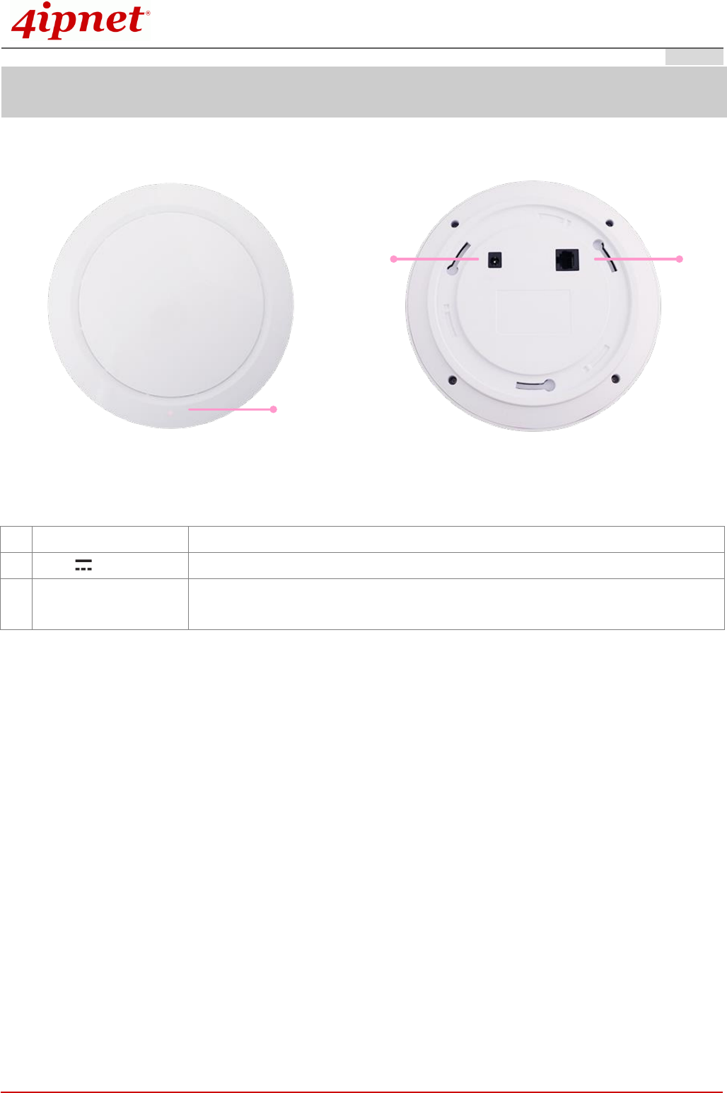
System Overview
1
2 3
EAP767’s Front Panel EAP767’s Rear Panel
1
LED Indicators
An LED indicator is available to show the uplink status
2
12V 2.5 A
Attach power adaptor here
3
Uplink (PoE) Port
Offers uplink connection. This port can be used to connect to a controller,
gateway, or directly to the Internet. 802.3at PoE is also supported
Quick Installation Guide
EAP767 Enterprise Access Point ENGLISH
Copyright © 4IPNET, INC. All rights reserved.
3
Hardware Installation
Please follow the steps mentioned below to install the hardware of EAP767:
1. Place the EAP767 at the best location.
a) The best location for EAP767 is usually at the center of your intended wireless network.
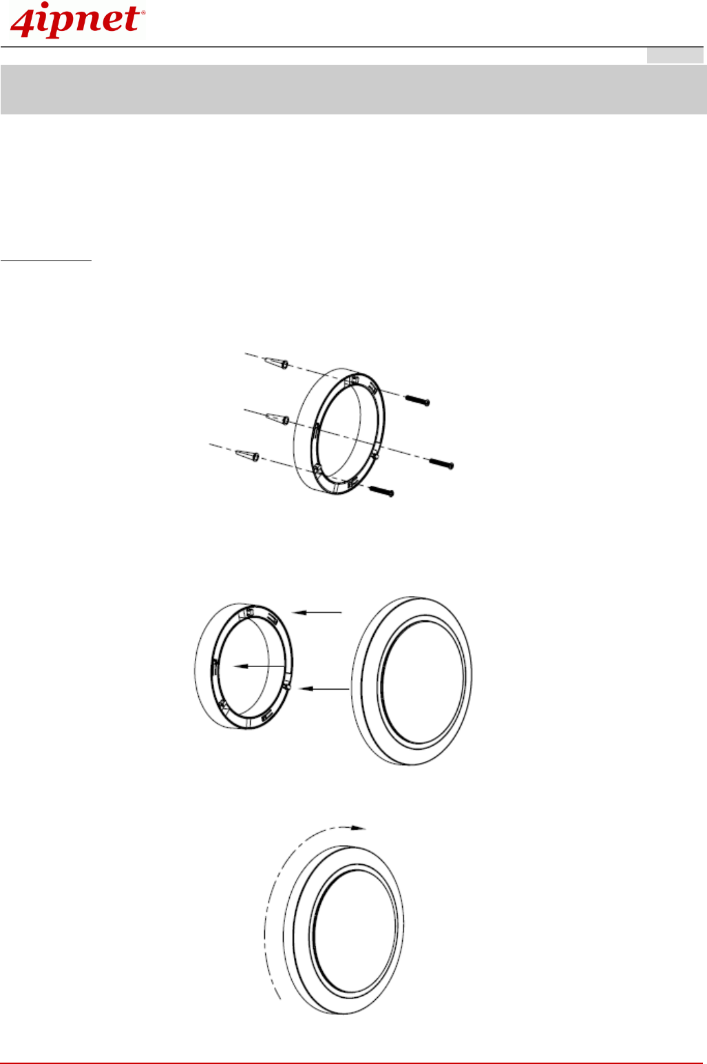
Wall Mounting
- Secure wall-mount bracket on wall
- Attach the Access Point to the dedicated slots on the mounting bracket
- Turn the Access Point clockwise as illustrated to fasten AP
Quick Installation Guide
EAP767 Enterprise Access Point ENGLISH
Copyright © 4IPNET, INC. All rights reserved.
4
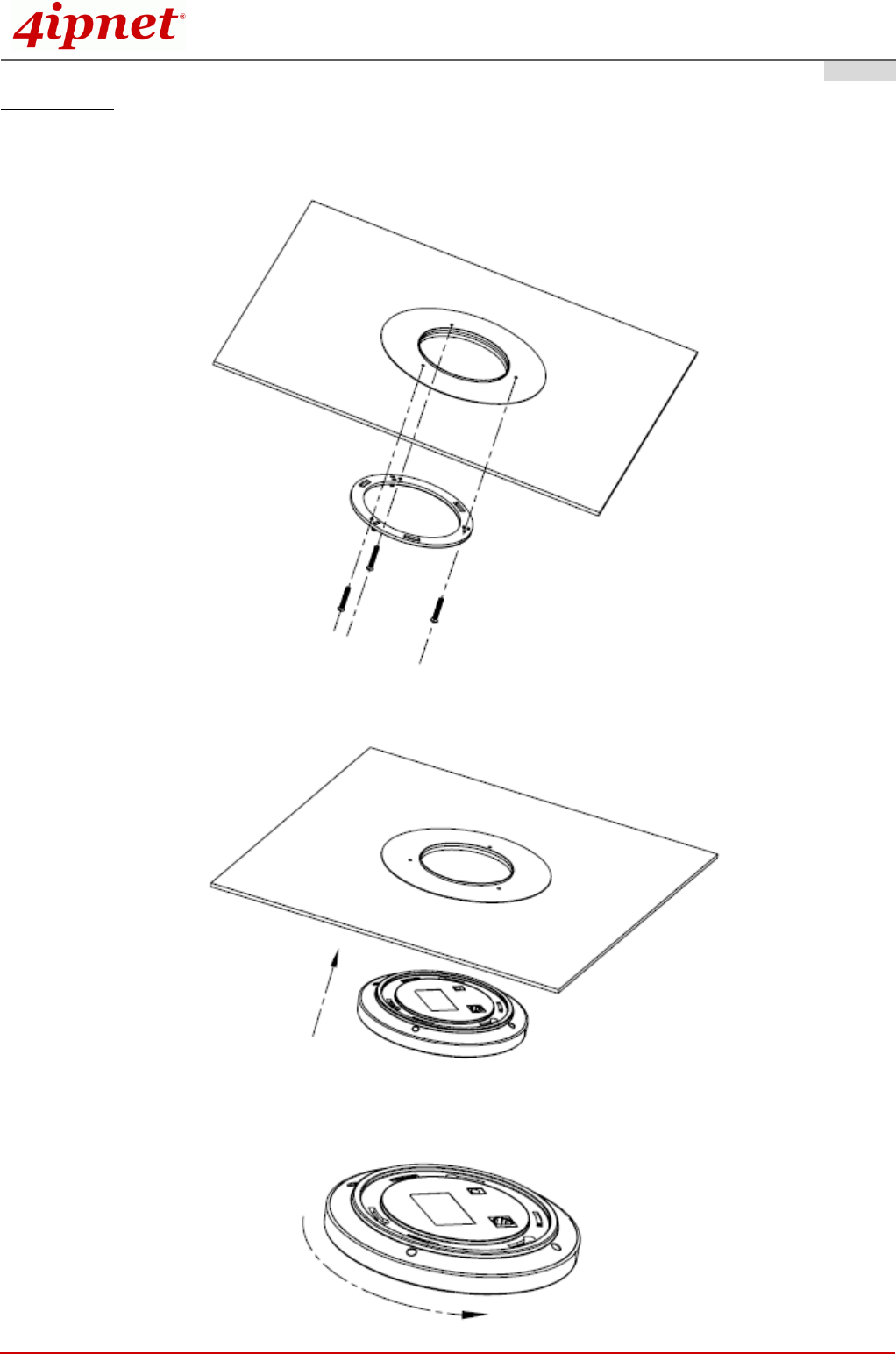
Ceiling Mount
- Secure ceiling-mount bracket on ceiling
- Attach the Access Point to the dedicated slots on the mounting bracket
- Turn the Access Point clockwise as illustrated to fasten AP
Quick Installation Guide
EAP767 Enterprise Access Point ENGLISH
Copyright © 4IPNET, INC. All rights reserved.
5
2. Connect the EAP767 to your network device.
Connect one end of the Ethernet cable to the Uplink port of EAP767 and the other end of the cable to a switch,
a router, or a hub. EAP767 is then connected to your existing wired LAN network.
There are two ways to supply power over to EAP767.
3. Connect the DC power adapter to the EAP767 power socket.
EAP767 Uplink port is capable of receiving DC currents. Connect an IEEE 802.3at-compliant PSE device (e.g.
a PoE-switch) to the Uplink port of EAP767 with the Ethernet cable.
Now, the Hardware Installation is complete.
Using a different power adapter may damage this system.
To verify the wired connection between EAP767 and you switch / router / hub, please also
check the LED status indicator of the respective network devices.
Quick Installation Guide
EAP767 Enterprise Access Point ENGLISH
Copyright © 4IPNET, INC. All rights reserved.
6
Getting Started
4ipnet EAP767 supports web-based configuration. When hardware installation is complete, EAP767 can be
configured through a PC by using a web browser such as Mozilla Firefox 2.0 or Internet Explorer version 6.0
and above.
The default values of LAN IP address and subnet mask of EAP767 are:
IP Address: 192.168.1.1
Subnet Mask: 255.255.255.0
Steps:
1. To access the Web Management Interface, connect the administrator PC to the Uplink port of EAP767 via
an Ethernet cable. Then, set a static IP address on the same subnet mask as EAP767 in TCP/IP of your
PC, such as the following example:
IP Address: 192.168.1.100
Subnet Mask: 255.255.255.0
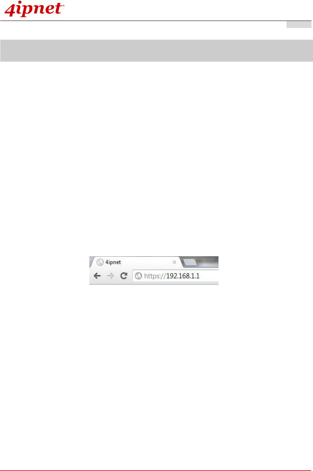
2. Launch the web browser on your PC by entering the IP address of EAP767 (https://192.168.1.1) in the
address field, and then press Enter.
Example of entering EAP767's default IP Address via a web browser
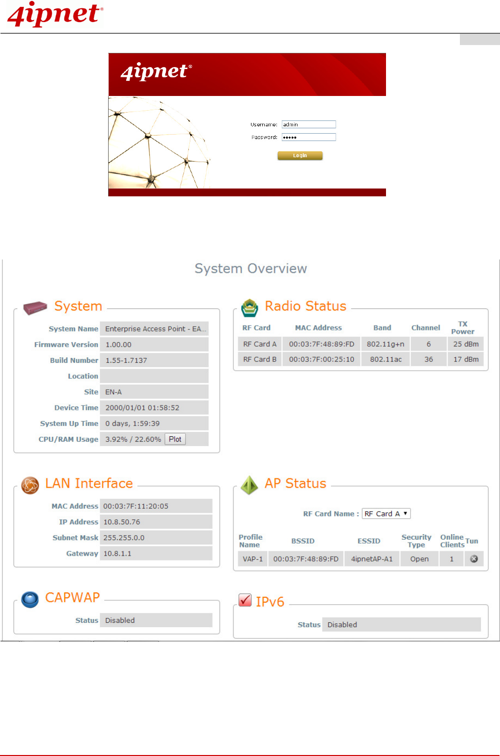
3. The following Admin Login Page will appear. Enter “admin” for both the Username and Password fields,
and then click Login.
Quick Installation Guide
EAP767 Enterprise Access Point ENGLISH
Copyright © 4IPNET, INC. All rights reserved.
7
Administrator Login Page
4. After a successful login to EAP767, a System Overview page of the Web Management Interface will
appear, as depicted below.
The Web Management Interface - System Overview Page
5. To logout, simply click on the Logout button at the upper right hand corner of the interface to return to the
Administrator Login Page. Click OK to logout.
Quick Installation Guide
EAP767 Enterprise Access Point ENGLISH
Copyright © 4IPNET, INC. All rights reserved.
8
Common Settings
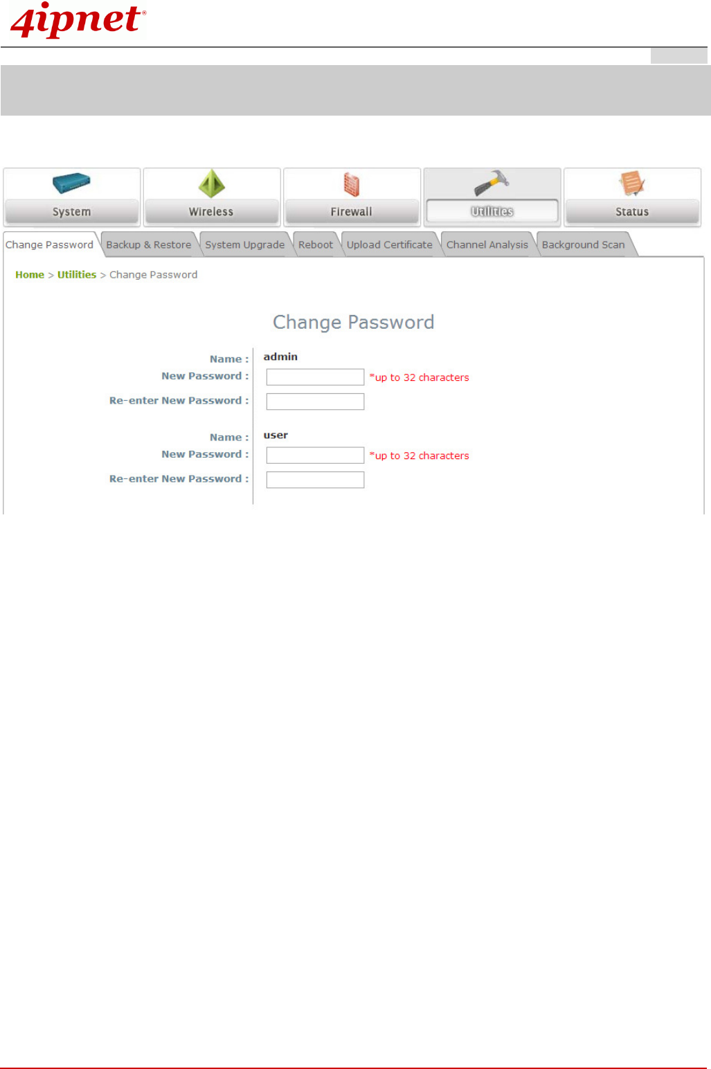
Step 1. Change Administrator’s Password
Change Password Page
Click on the Utilities icon on the main menu, and select the Change Password tab.
Enter the old password and then a new password with a length of up to 32 characters, and retype it in
the Re-enter New Password field.
Click SAVE to save the changes.
Quick Installation Guide
EAP767 Enterprise Access Point ENGLISH
Copyright © 4IPNET, INC. All rights reserved.
9
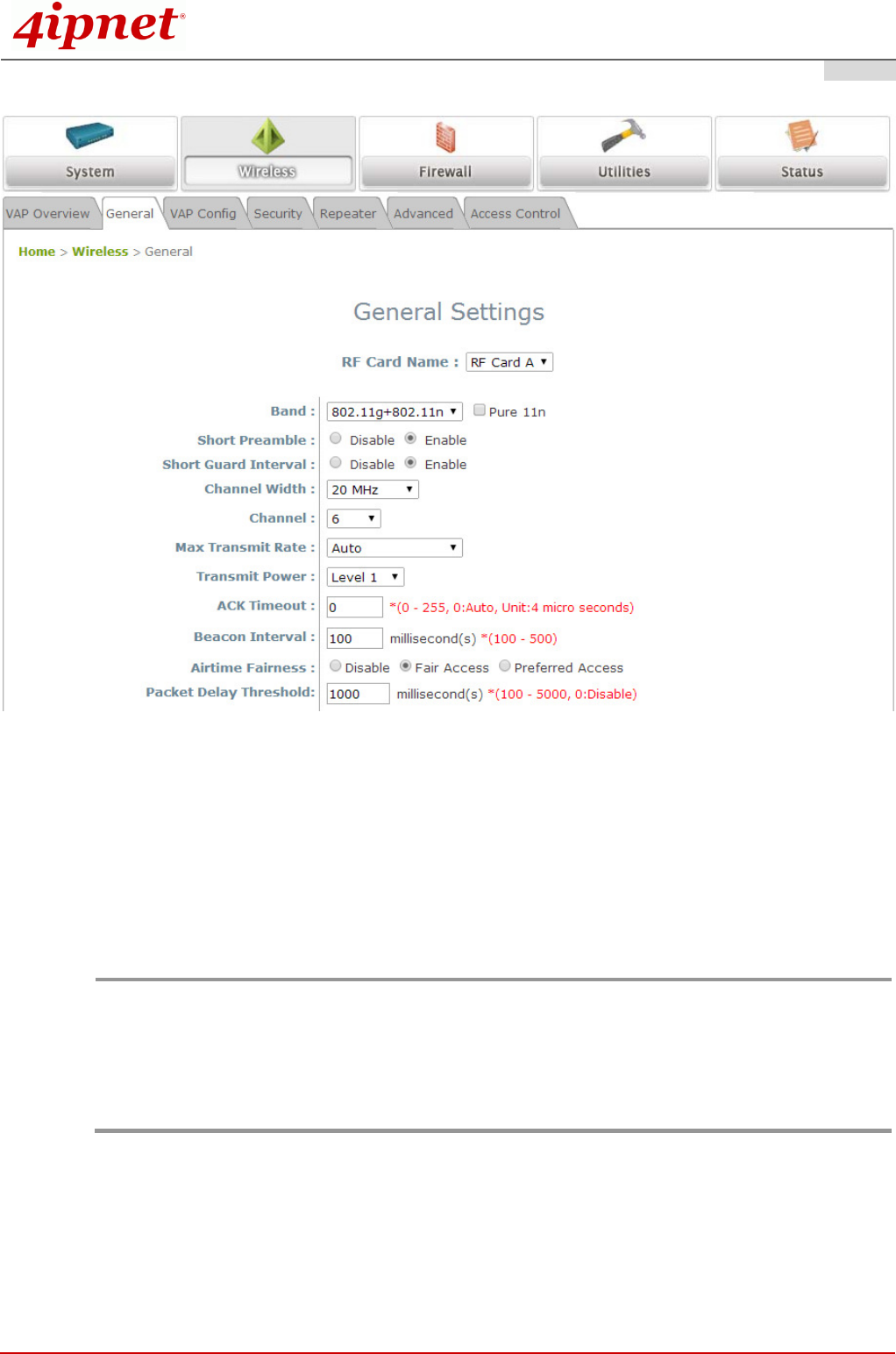
Step 2. Configure General AP (Access Point) Settings
Wireless General Settings Page
Click on the Wireless icon on the main menu, and then select the General tab.
Determine the Band and Channel settings:
Select your preferred Band and Channel for you wireless connection. For example, select
802.11g+802.11n for the band and 6 for the channel. For a detailed guide to configuration, please
refer to the EAP767 User Manual.
Note:
Admin should be aware of Dynamic Frequency Selection (DFS) mandated on some channels of the
5GHz band. When an EAP767 detects interference, this mechanism will limit the ability to broadcast
the SSID on one of the channels listed below:
1) Country Code: 840 (US)
DFS Channels: 52 56 60 64 100 104 108 112 116 120 124 128 132 136 140
2) Country Code: 250 (EU)
DFS Channels: 52 56 60 64
Quick Installation Guide
EAP767 Enterprise Access Point ENGLISH
Copyright © 4IPNET, INC. All rights reserved.
10
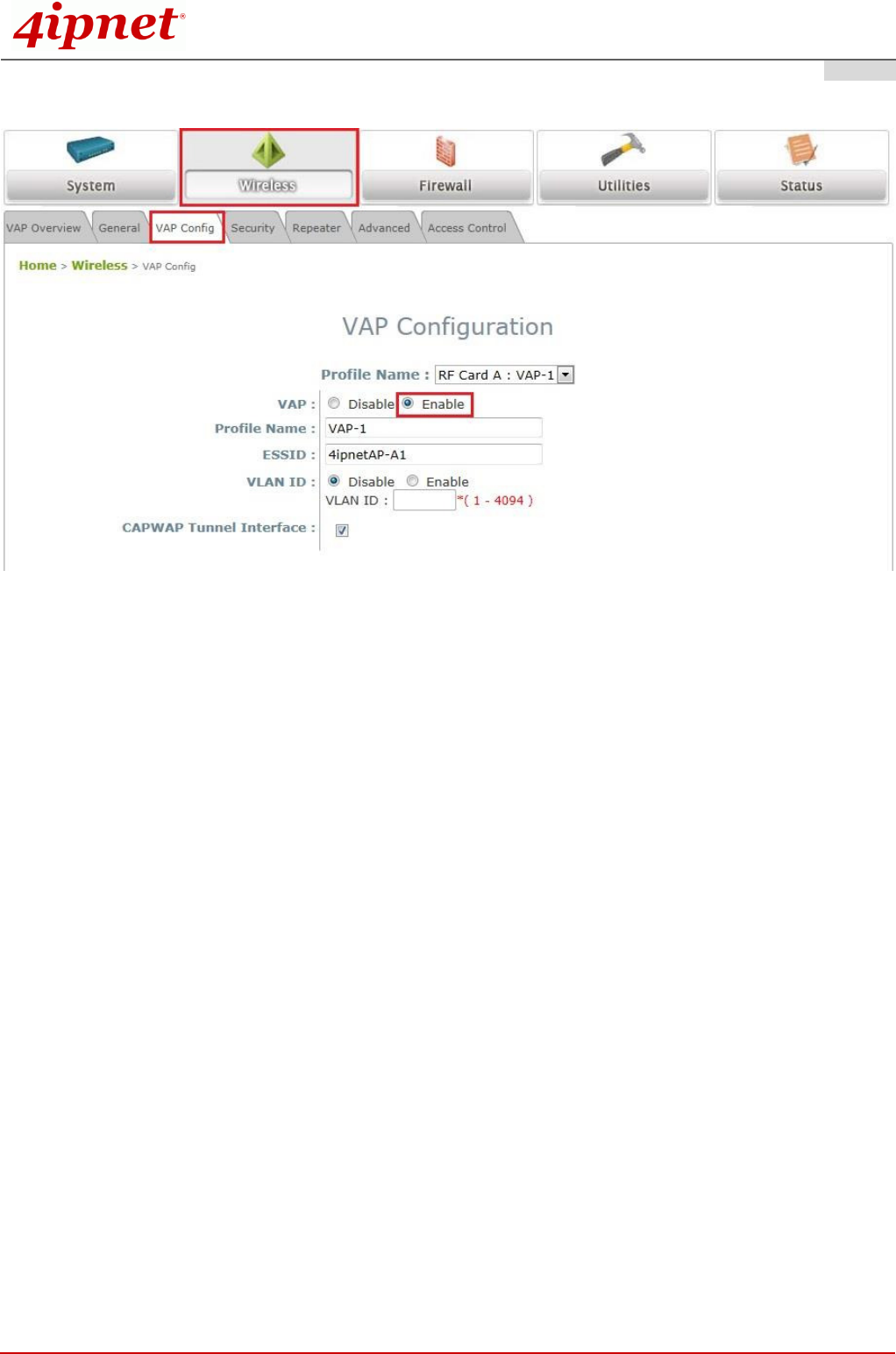
Step 3. Configure VAP (Virtual Access Point) Profile Settings
VAP Configuration Page (VAP-1 shown)
EAP767 supports up to 16 virtual APs (VAPs) per RF Card.
Configure VAP profile settings
(a) Select the VAP Configuration tab to configure the settings of the desired VAP.
(b) Enable a specific VAP from the drop-down menu of Profile Name and configure related settings
below.
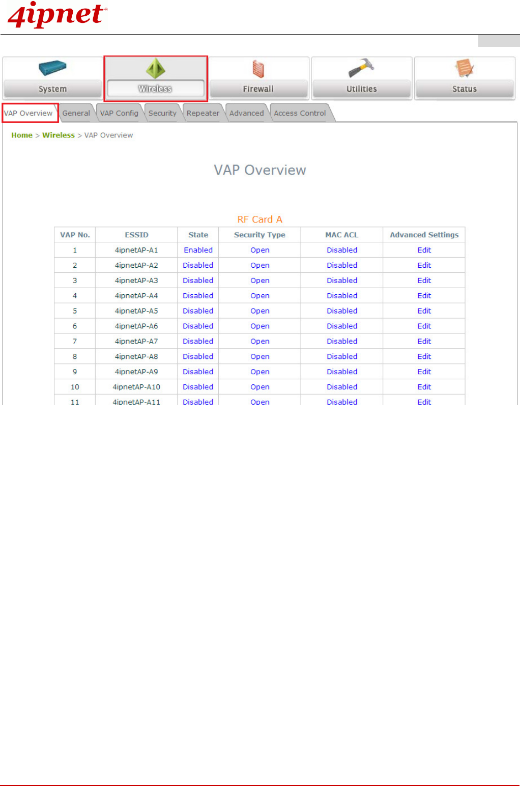
Check VAP status
After finishing VAP configuration, the status of enabled Virtual APs shall be reflected on the VAP
Overview page.
Quick Installation Guide
EAP767 Enterprise Access Point ENGLISH
Copyright © 4IPNET, INC. All rights reserved.
11
Virtual AP Overview Page
Quick Installation Guide
EAP767 Enterprise Access Point ENGLISH
Copyright © 4IPNET, INC. All rights reserved.
12
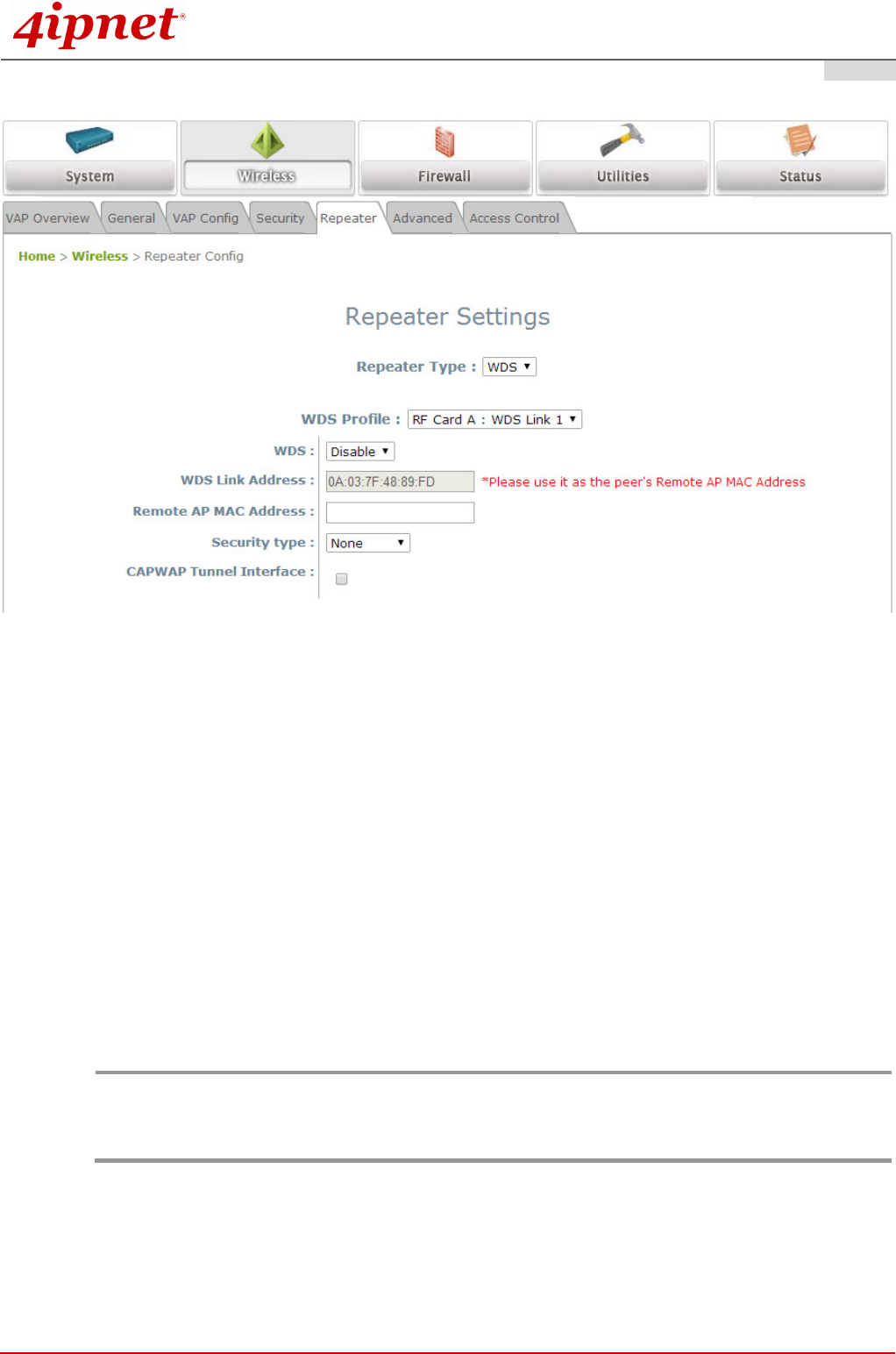
Step 4. Configure WDS (Wireless Distribution System) Settings (Optional)
To extend the wireless coverage, EAP767 supports up to 8 WDS links for connecting wirelessly to other
WDS-capable APs (peer APs). By default, all WDS profiles are disabled.
Click on the Wireless button on the main menu.
Select the Repeater Settings tab.
Choose WDS as the Repeater Type.
Choose the desired WDS profile:
(a) Enable WDS.
(b) Enter the MAC Address (peer AP) and then Click SAVE.
If you are using another EAP767 as the peer AP, simply repeat the above-mentioned steps to configure
another peer AP(s).
Note:
On each and every configuration page, you may click SAVE to save the changes of your configured
settings, but you must reboot the system for the changes to take effect. After clicking SAVE, the
following message will appear: “Some modifications have been saved and will take effect after
Reboot.”
Congratulations!
Now, 4ipnet EAP767 is installed and configured successfully.

Quick Installation Guide
EAP767 Enterprise Access Point ENGLISH
Copyright © 4IPNET, INC. All rights reserved.
13
After EAP767's network configuration is completed, please remember to change the IP Address of
your PC Connection Properties back to its original settings in order to ensure that your PC functions
properly in its real network environments.
It is strongly recommended to make a backup copy of your configuration settings.
For further configuration and backup information, please refer to the User’s Manual.
P/N: V10020140509