4RF SR135M130 VHF POINT TO POINT DIGITAL TRANSCEIVER User Manual 2
4RF Limited VHF POINT TO POINT DIGITAL TRANSCEIVER 2
4RF >
Contents
- 1. User Manual 1
- 2. User Manual 2
User Manual 2

98 | Managing the Radio
Aprisa SR User Manual
Packet Size (Bytes)
This parameter sets the maximum over-the-air packet size in bytes. A smaller maximum Packet Size is
beneficial when many remote stations or repeater stations are trying to access the channel. The default
setting is 1550 bytes.
As radios dispatched from the factory have a Packet Size set to the maximum value of 1550 bytes, if a new
radio is installed in an existing Field Access Network (network), the Packet Size must be changed to ensure
it is the same value for all radios in the network. The new radio will not register an existing network if the
Packet Size is not the same as the other radios in the network.
This packet size includes the wireless protocol header and security payload (0 to 16 bytes). The length of
the security header depends on the level of security selected.
When the security setting is 0, the maximum user data transfer over-the-air is 1516 bytes.
When encryption is enabled, the entire packet of user data (payload) is encrypted. If authentication is
being used, the security frame will be added (up to 16 bytes). The wireless protocol header is then added
which is proprietary to the Aprisa SR. This is not encrypted.
Packet Time to Live (ms)
This Time To Live (TTL) parameter sets the time a packet is allowed to live in the system before being
dropped if it cannot be transmitted over the air. It is used to prevent old, redundant packets being
transmitted through the Aprisa SR network. The default setting is 1500 ms.
In the case of serial poll SCADA networks such as MODBUS and IEC 60870.50.101, it is important to ensure
the replies from the RTU are in the correct sequence and are not timed out replies from Master requests.
If the TTL value is too long, the SCADA master will detect sequence errors.
It is recommended to use a TTL which is half the serial SCADA timeout. This is commonly called the ‘scan
timeout’ or ‘link layer time out’ or ‘retry timeout’.
When using TCP protocols, a TTL of 1500 ms is recommended because a TCP re-transmission usually occurs
after approximately 3 second.
In SCADA networks which use both serial and Ethernet, it is recommended that the TTL is set to half the
serial SCADA timeout for serial remotes, and 1500 ms for Ethernet (TCP) remotes. For example, if the
serial SCADA timeout is 1000 ms, a remote radio which is connected to the serial RTU should be set to
500 ms, a remote radio which is connected to a Ethernet (TCP) RTU should have a 1500 ms timeout.
In this case, the base station TTL should be set to 1500 ms as well; or which ever is the longer TTL of
serial or Ethernet.
Managing the Radio | 99
Aprisa SR User Manual
Packet Filtering
Each Aprisa SR radio can filter packets not destined for itself. The Packet Filtering parameter controls this
functionality.
In an Aprisa SR network, all communication from remote stations is destined for the base station in the
Aprisa SR network communication protocol. In a repeater network, a remote station will send a message
to the base station. The repeater station will receive this and then repeat the message. The repeated
message will then be received by the base station. Other remote stations connected to the repeater
station will receive this message and depending on the Packet Filtering parameter, either forward this
packet or discard it.
This filtering capability can provide the ability for remote stations to communicate with each other when
connected to a repeater, particularly useful in the event of losing communication with a SCADA Master,
assuming the Aprisa SR network is still operational.
Note: IP Header Compression must be disabled for this feature to operate correctly (see ‘IP Header
Compression Ratio’ on page 101).
Option
Function
Disabled
Every packet received by the radio will be forwarded to the
relevant interface.
Automatic
The radio will filter (discard) packets not destined for itself
according to the Aprisa SR traffic protocols
The default setting is Automatic.
Note: The Aprisa SR network is transparent to the protocol being transmitted; therefore the Packet
Filtering parameter is based on the Aprisa SR addressing and network protocols, not the user (SCADA, etc.)
traffic protocols.
Serial Data Stream Mode
This parameter controls the traffic flow in the radio serial ports.
Option
Function
Broadcast
Serial port traffic from the network is broadcast on all serial ports
on this radio. This will include the RS-232 port derived from the
USB port.
Segregate
Serial port traffic from the network from a specific port number is
directed to the respective serial port only.
The default setting is Broadcast.

100 | Managing the Radio
Aprisa SR User Manual
TRAFFIC SETTINGS
Serial Data Priority
The Serial Data Priority controls the priority of the serial customer traffic relative to the Ethernet
customer traffic. If equal priority is required to Ethernet traffic, this setting must be the same as the
Ethernet Data Priority setting (see ‘Ethernet Data Priority’ on page 100).
The serial data priority can be set to Very High, High, Medium and Low. The default setting is Very High.
A queuing system is used to prioritize traffic from the serial and Ethernet interfaces for over the air
transmission. A weighting may be given to each data type and this is used to schedule the next
transmission over the air e.g. if there are pending data packets in multiple buffers but serial data has a
higher weighting it will be transmitted first. The serial buffer is 20 serial packets (1 packet can be up to
512 bytes).
There are four priority queues in the Aprisa SR: Very High, High, Medium and Low. Data is added to one of
these queues depending on the priority setting. Data leaves the queues from highest priority to lowest:
the Very High queue is emptied first, followed by High then Medium and finally Low.
Ethernet Data Priority
The Ethernet Data Priority controls the priority of the Ethernet customer traffic relative to the serial
customer traffic. If equal priority is required to serial traffic, this setting must be the same as the Serial
Data Priority setting (see ‘Serial Data Priority’ on page 100)
The Ethernet Data Priority can be set to Very High, High, Medium and Low. The default setting is Very
High.
A queuing system is used to prioritize customer traffic from the serial and Ethernet interfaces for over the
air transmission. A weighting may be given to each data type and this is used to schedule the next
transmission over the air e.g. if there are pending data packets in multiple buffers but serial data has a
higher weighting it will be transmitted first. The Ethernet buffer is 10 Ethernet packets (1 packet can be
up to Ethernet MTU, 1500 bytes).
There are four priority queues in the Aprisa SR: Very High, High, Medium and Low. Data is added to one of
these queues depending on the priority setting. Data leaves the queues from highest priority to lowest:
the Very High queue is emptied first, followed by High then Medium and finally Low.
Ethernet Management Priority
The Ethernet Management Priority controls the priority of the Ethernet management traffic relative to
Ethernet customer traffic.
The Ethernet Management Priority can be set to Very High, High, Medium and Low. The default setting is
Medium.
Managing the Radio | 101
Aprisa SR User Manual
Background Bulk Data Transfer Rate
This parameter sets the data transfer rate for large amounts of management data.
Option
Function
High
Utilizes more of the available capacity for large amounts of
management data. Highest impact on user traffic.
Medium
Utilizes a moderate of the available capacity for large amounts of
management data. Medium impact on user traffic.
Low
Utilizes a minimal of the available capacity for large amounts of
management data. Lowest impact on user traffic.
The default setting is high.
DATA COMPRESSION
IP Header Compression Ratio
The IP Header Compression implements TCP/IP ROHC v2 (Robust Header Compression v2. RFC4995,
RFC5225, RFC4996) to compress the IP header. IP Header Compression allows for faster point to point
transactions, but only in a star network.
IP Header Compression module comprises of two main components, Compressor and Decompressor. Both
these components maintain some state information for an IP flow to achieve header compression.
However, for reasons like packet drops or station reboots this state information can go out of sync
between compressor and decompressor resulting in compression and/or decompression failure resulting in
loss of packets.
The Compression Ratio controls the rate at which compressor and decompressor synchronize state
information with each other. Frequent synchronization results in reduced ratio.
Option
Function
Compression
Disabled
Disables IP Header Compression.
High
State information is synchronized less frequently thus achieving
the best compression ratio.
Medium
State information is synchronization less frequently than ‘High’
setting but more frequently than ‘Low’ setting.
Low
State information is synchronized frequently thus reducing the
compression ratio.
The default setting is High.
When IP Header Compression is enabled, it is important that the Network Radius is set correctly. If it was
incorrectly set to 1, header compression could not be interpreted by radius 2 radios.
102 | Managing the Radio
Aprisa SR User Manual
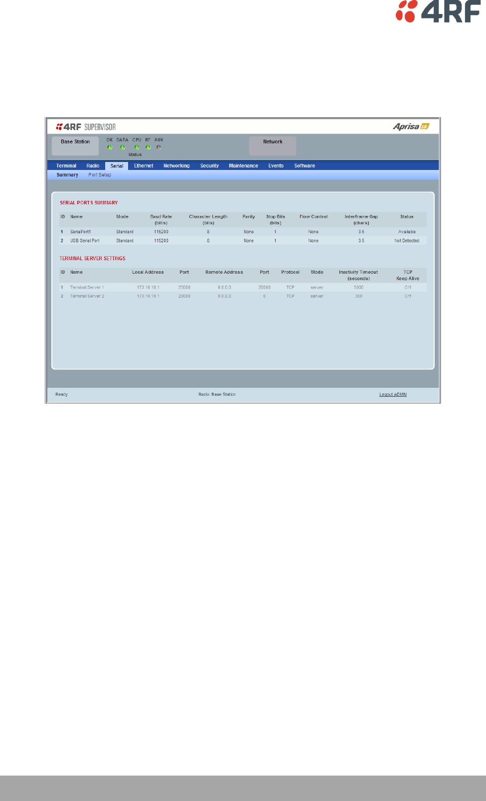
Serial
Serial > Summary
This page displays the current settings for the serial port parameters.
See ‘Serial > Port Setup’ on page 103 for configuration options.
Managing the Radio | 103
Aprisa SR User Manual
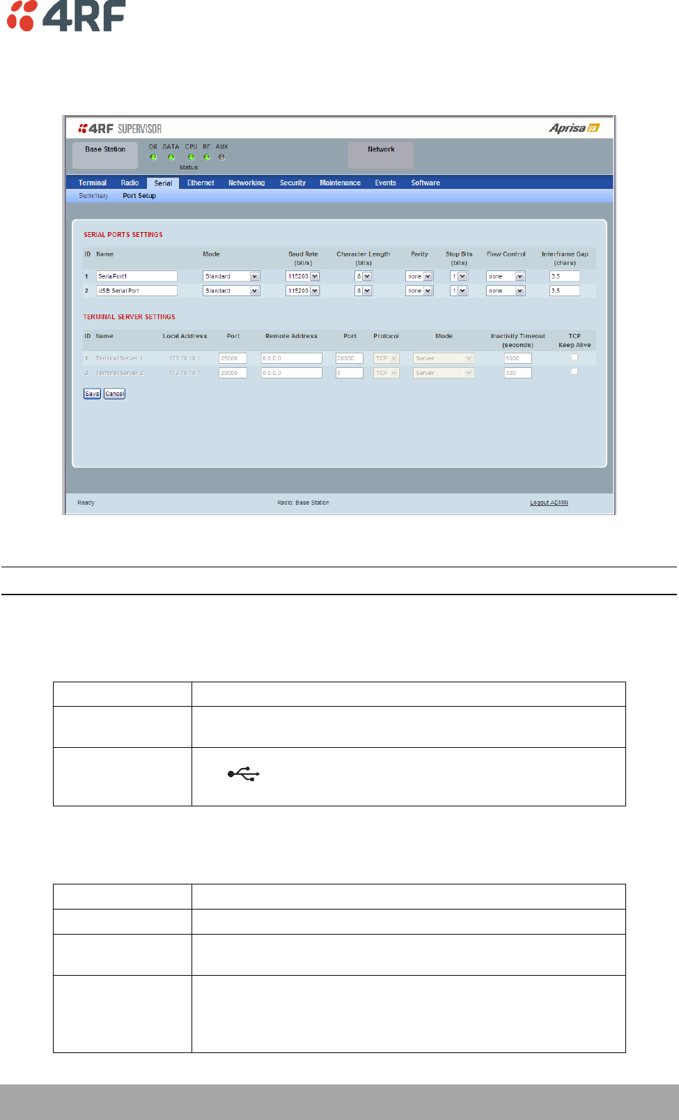
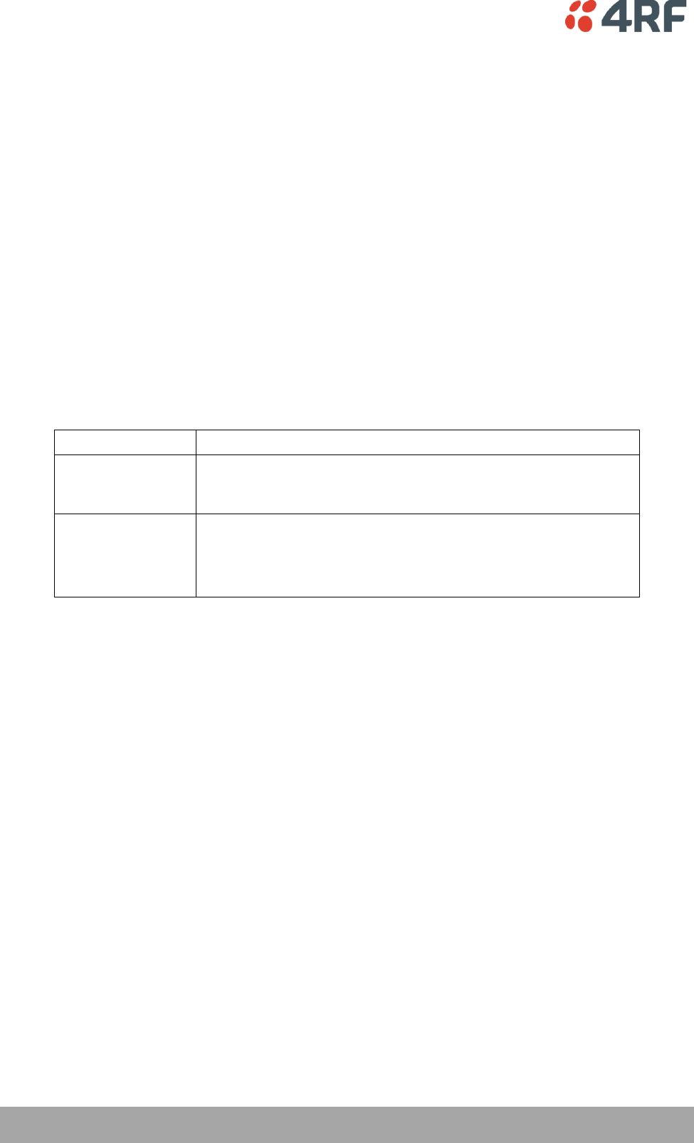
Serial > Port Setup
This page provides the setup for the serial port settings.
SERIAL PORTS SETTINGS
Note: The current Aprisa SR has one serial port so there will be only one record.
Name
This parameter sets the port name which can be up to 32 characters.
Option
Function
SerialPort1
This is the normal RS-232 serial port provided with the RJ45
connector.
USB Serial Port
This is the additional RS-232 serial port provided with the USB Host
Port connector with a USB to RS-232 RJ45 converter cable
(see ‘USB RS-232 Serial Port’ on page 43).
Mode
This parameter defines the mode of operation of the serial port. The default setting is Standard.
Option
Function
Disabled
The serial port is not required.
Standard
The serial port is communicating with serial ports on other
stations.
Terminal Server
A base station Ethernet port can communicate with both Ethernet
ports and serial ports on remote stations.
RS-232 traffic is encapsulated in IP packets (see ‘Serial > Port
Setup’ TERMINAL SERVER SETTINGS on page 105).
104 | Managing the Radio
Aprisa SR User Manual
Baud Rate (bit/s)
This parameter sets the baud rate to 300, 1200, 2400, 4800, 9600, 19200, 38400, 57600 or 115200 bit/s.
The default setting is 115200 bit/s.
Character Length (bits)
This parameter sets the character length to 7 or 8 bits. The default setting is 8 bits.
Parity
This parameter sets the parity to Even, Odd or None. The default setting is None.
Stop Bits (bits)
This parameter sets the number of stop bits to 1 or 2 bits. The default setting is 1 bit.
Flow Control
This parameter sets the flow control of the serial port. The default setting is Disabled.
Option
Function
None
The Aprisa SR radio port (DCE) CTS is in a permanent ON (+ve)
state.
This does not go to OFF if the radio link fails.
CTS-RTS
CTS / RTS hardware flow control between the DTE and the Aprisa
SR radio port (DCE) is enabled.
If the Aprisa SR buffer is full, the CTS goes OFF.
In the case of radio link failure the signal goes to OFF (-ve) state.
In terminal server mode, the serial packet is no different from an Ethernet packet and travels through
various packet queues before being transmitted over the air. Thus, the serial flow control has no affect in
terminal server mode.
Inter-Frame Gap (chars)
This parameter defines the gap between successive serial data frames. It is used to delimit the serial data
to define the end of a packet. The Inter-Frame Gap limits are 0.5 to 16 chars. The default setting is 3.5
chars.
Managing the Radio | 105
Aprisa SR User Manual
TERMINAL SERVER SETTINGS
This menu item is only applicable if the serial port has an operating mode of Terminal Server.
The Terminal Server operating mode provides encapsulation of serial data into an IP packet (TCP or UDP).
A server connected to a base station Ethernet port can communicate with all remote station Ethernet
ports and serial ports.
Note: The current Aprisa SR has one serial port so there will be only one record.
Local Address
This parameter displays the IP address of this radio.
Port
This parameter sets the port number of the local serial port.
The valid port number range is greater than or equal to 1024 and less than or equal to 49151 but with
exclusions of 0, 5445, 6445, 9930 or 9931. The default setting is 20000.
Remote Address
This parameter sets the IP address of the server connected to the base station Ethernet port.
Port
This parameter sets the port number of the server connected to the base station Ethernet port. The
default setting is 0.

106 | Managing the Radio
Aprisa SR User Manual
Protocol
This parameter sets the IP protocol used for terminal server operation. The default setting is TCP.
Mode
This parameter defines the mode of operation of the terminal server connection. The default setting is
Client and Server.
Option
Function
Client
The radio will attempt to establish a TCP connection with the
specified remote unit.
Server
The radio will listen for a TCP connection on the specified local
port.
Data received from any client shall be forwarded to the associated
serial port while data received from that serial port shall be
forwarded to every client with an open TCP connection.
If no existing TCP connections exist, all data received from the
associated serial port shall be discarded.
Client and Server
The radio will listen for a TCP connection on the specified local
port and if necessary, establish a TCP connection with the
specified remote unit.
Data received from any client shall be forwarded to the associated
serial port while data received from that serial port shall be
forwarded to every client with an open TCP connection.
Inactivity Timeout (seconds)
This specifies the duration (in seconds) to automatically terminate the connection with the remote TCP
server if no data has been received from either the remote TCP server or its associated serial port for the
duration of the configured inactivity time.
TCP Keep Alive
A TCP keepalive is a message sent by one device to another to check that the link between the two is
operating, or to prevent the link from being broken.
If the TCP Keep Alive is enabled, the radio will be notified if the TCP connection fails.
If the TCP Keep Alive is disabled, the radio relies on the Inactivity Timeout to detect a TCP connection
failure. The default setting is disabled.
Note: An active TCP Keep Alive will generate a small amount of extra network traffic.
Managing the Radio | 107
Aprisa SR User Manual
Ethernet
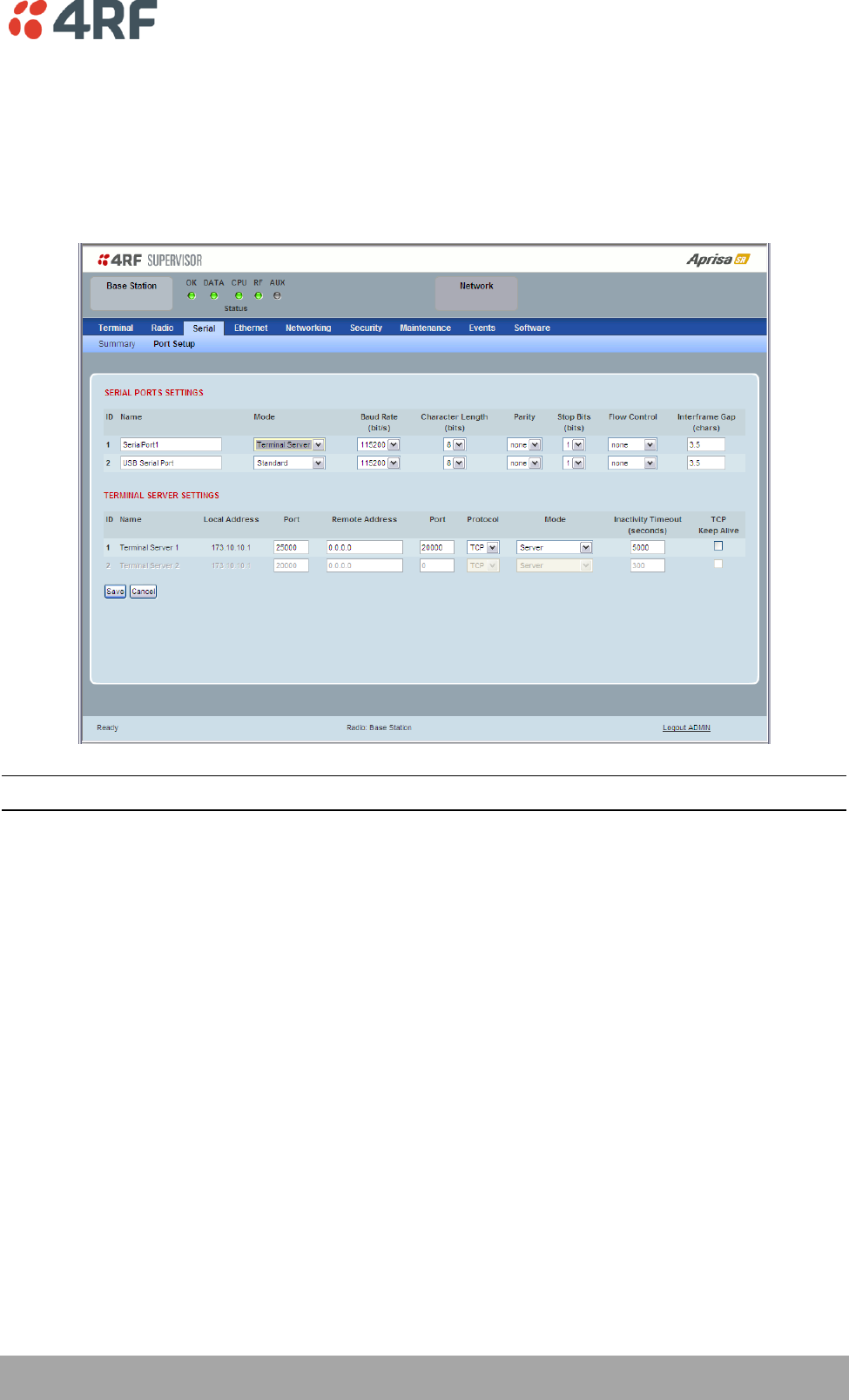
Ethernet > Summary
This page displays the current settings for the Ethernet port parameters and the status of the ports.
See ‘Ethernet > Port Setup’ for configuration options.
108 | Managing the Radio
Aprisa SR User Manual
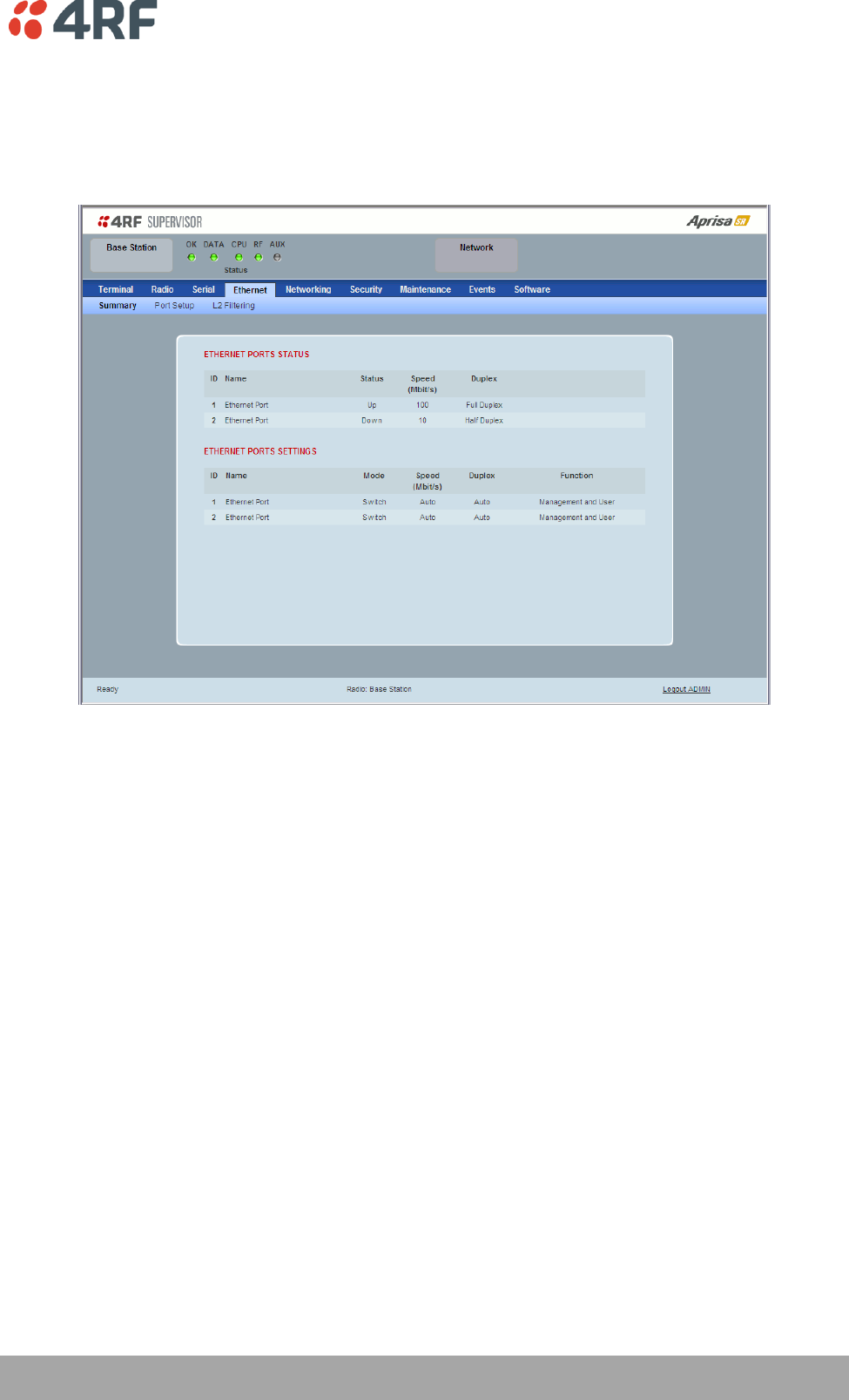
Ethernet > Port Setup
This page provides the setup for the Ethernet ports settings.
ETHERNET PORT SETTINGS
Mode
This parameter controls the Ethernet traffic flow. The default setting is Standard.
Option
Function
Standard
Enables Ethernet data communication over the radio link.
Switch
Ethernet traffic is switched locally between the two
Ethernet ports and communicated over the radio link
Disabled
Disables Ethernet data communication over the radio link.
Speed (Mbit/s)
This parameter controls the traffic rate of the Ethernet port. The default setting is Auto.
Option
Function
Auto
Provides auto selection of Ethernet Port Speed
10
The Ethernet Port Speed is manualy set to 10 Mbit/s
100
The Ethernet Port Speed is manualy set to 100 Mbit/s

Managing the Radio | 109
Aprisa SR User Manual
Duplex
This parameter controls the transmission mode of the Ethernet port. The default setting is Auto.
Option
Function
Auto
Provides auto selection of Ethernet Port duplex setting.
Half Duplex
The Ethernet Port is manualy set to Half Duplex.
Full Duplex
The Ethernet Port is manualy set to Full Duplex.
Function
This parameter controls the use for the Ethernet port. The default setting is Management and User.
Option
Function
Management Only
The Ethernet port is only used for management of the
network.
Management and User
The Ethernet port is used for management of the network
and User traffic over the radio link.
User Only
The Ethernet port is only used for User traffic over the radio
link.
110 | Managing the Radio
Aprisa SR User Manual
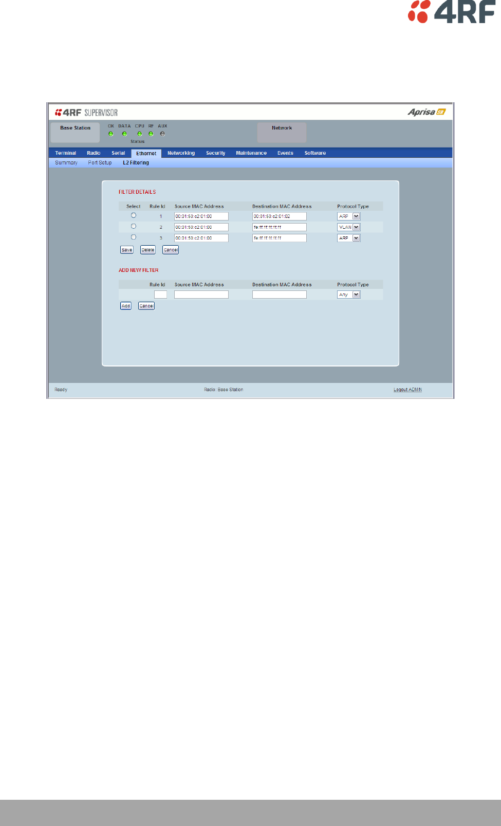
Ethernet > L2 Filtering
This page is only available if the Ethernet traffic option has been licensed (see ‘Maintenance > Licence’ on
page 140).
FILTER DETAILS
L2 Filtering provides the ability to filter radio link traffic based on specified Layer 2 MAC addresses.
Traffic originating from specified Source MAC Addresses destined for specified Destination MAC Addresses
that meets the protocol type criteria will be transmitted over the radio link.
Traffic that does not meet the filtering criteria will not be transmitted over the radio link.
Source MAC Address
This parameter sets the filter to the Source MAC address of the packet in the format ‘hh:hh:hh:hh:hh:hh’.
If the Source MAC Address is set to ‘FF:FF:FF:FF:FF:FF’, traffic will be accepted from any source MAC
address.
Destination MAC Address
This parameter sets the filter to the Destination MAC address of the packet in the format
‘hh:hh:hh:hh:hh:hh’.
If the Destination MAC Address is set to ‘FF:FF:FF:FF:FF:FF’, traffic will be delivered to any destination
MAC address.
Protocol Type
This parameter sets the Ethernet Type accepted ARP, VLAN, IPv4, IPv6 or Any type.
Managing the Radio | 111
Aprisa SR User Manual
Example:
In the screen shot, the rules are configured in the base station which controls the radio link traffic from
base station to remote / repeater stations.
Traffic from a device with the MAC address 00:01:50:c2:01:00 is forwarded over the radio link if it meets
the criteria:
Rule 1 If the Ethernet Type is ARP going to any destination MAC address or
Rule 2 If the Ethernet Type is Any and the destination MAC address is 01:00:50:c2:01:02 or
Rule 3 If the Ethernet Type is VLAN tagged packets going to any destination MAC address
Special L2 Filtering Rules:
Unicast Only Traffic
This L2 filtering allows for Unicast only traffic and drop broadcast and multicast traffic. This filtering is
achieved by adding the two rules:
Rule
Source
MAC Address
Destination
MAC Address
Protocol Type
Allow ARPS
FF:FF:FF:FF:FF:FF
FF:FF:FF:FF:FF:FF
ARP
Allow Unicasts from Any source
FF:FF:FF:FF:FF:FF
FE:FF:FF:FF:FF:FF
Any
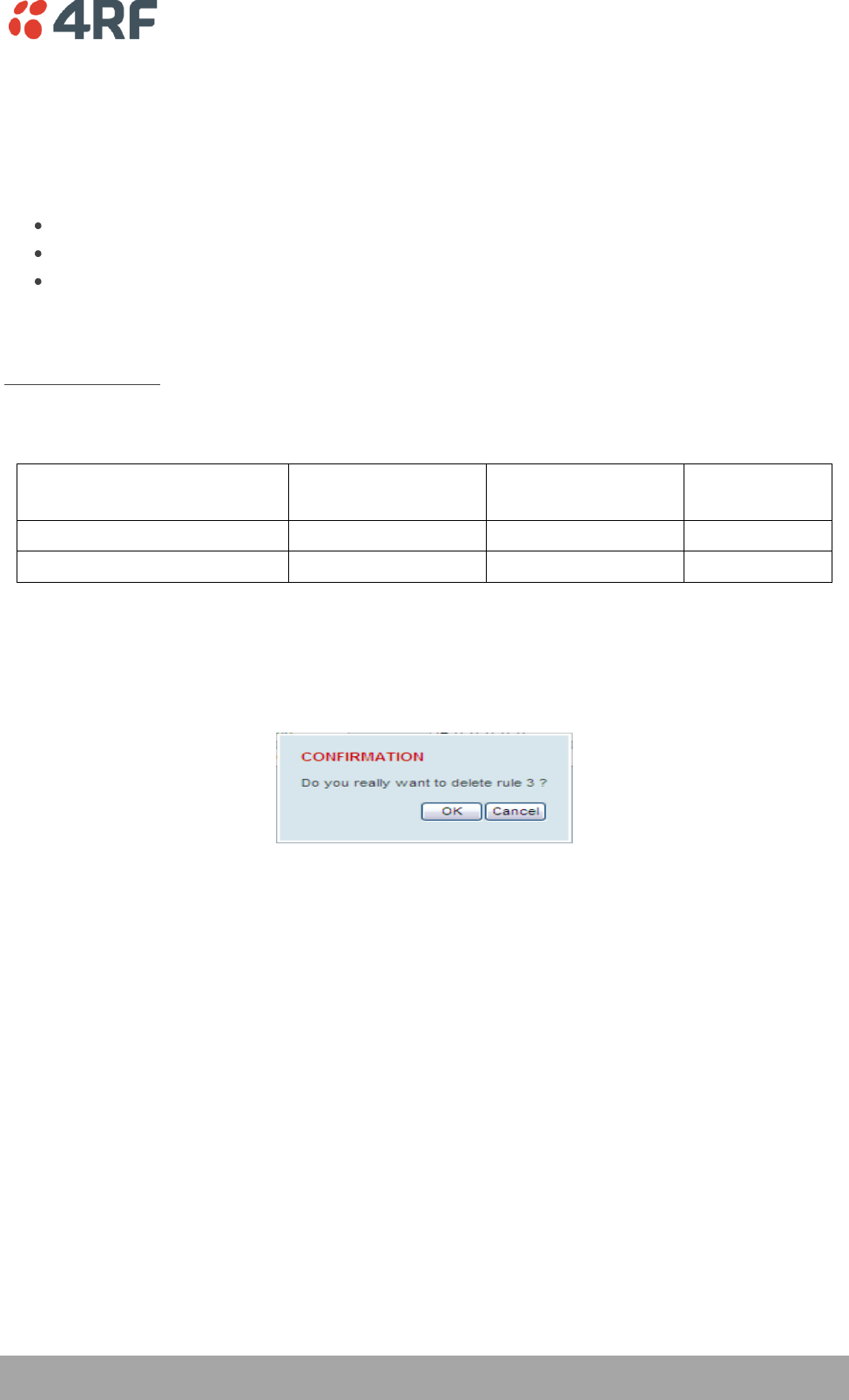
To delete a L2 Filter:
1. Click on an existing rule ‘Select’.
2. Click on Delete.
3. Click on OK.
ADD NEW FILTER
To add a L2 Filter:
1. Enter the Rule ID number. This is a unique rule number between 1 and 25.
2. Enter the Source MAC address of the packet or ‘FF:FF:FF:FF:FF:FF’ to accept traffic from any MAC
address.
3. Enter the Destination MAC address of the packet or ‘FF:FF:FF:FF:FF:FF’ to deliver traffic to any MAC
address.
4. Select the Protocol Type to ARP, VLAN, IPv4, IPv6 or Any type.
5. Click on Add.
112 | Managing the Radio
Aprisa SR User Manual
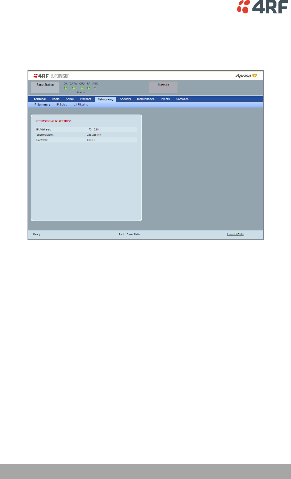
Networking
Networking > IP Summary
This page displays the current settings for the Networking IP Settings.
See ‘Networking > IP Setup’ for configuration options.
Managing the Radio | 113
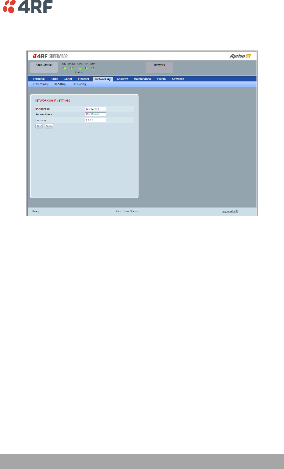
Aprisa SR User Manual
Networking > IP Setup
This page provides the setup for the Networking IP Settings.
NETWORKING IP SETTINGS
IP Address
Set the static IP Address of the radio assigned by your site network administrator using the standard
format xxx.xxx.xxx.xxx. The default IP address is in the range 169.254.50.10.
Subnet Mask
Set the Subnet Mask of the radio using the standard format xxx.xxx.xxx.xxx. The default subnet mask is
255.255.0.0.
Gateway
Set the Gateway address of the radio, if required, using the standard format xxx.xxx.xxx. The default
Gateway is 0.0.0.0.
114 | Managing the Radio
Aprisa SR User Manual
Networking > L3 Filtering
This page is only available if the Ethernet traffic option has been licensed (see ‘Maintenance > Licence’ on
page 140).
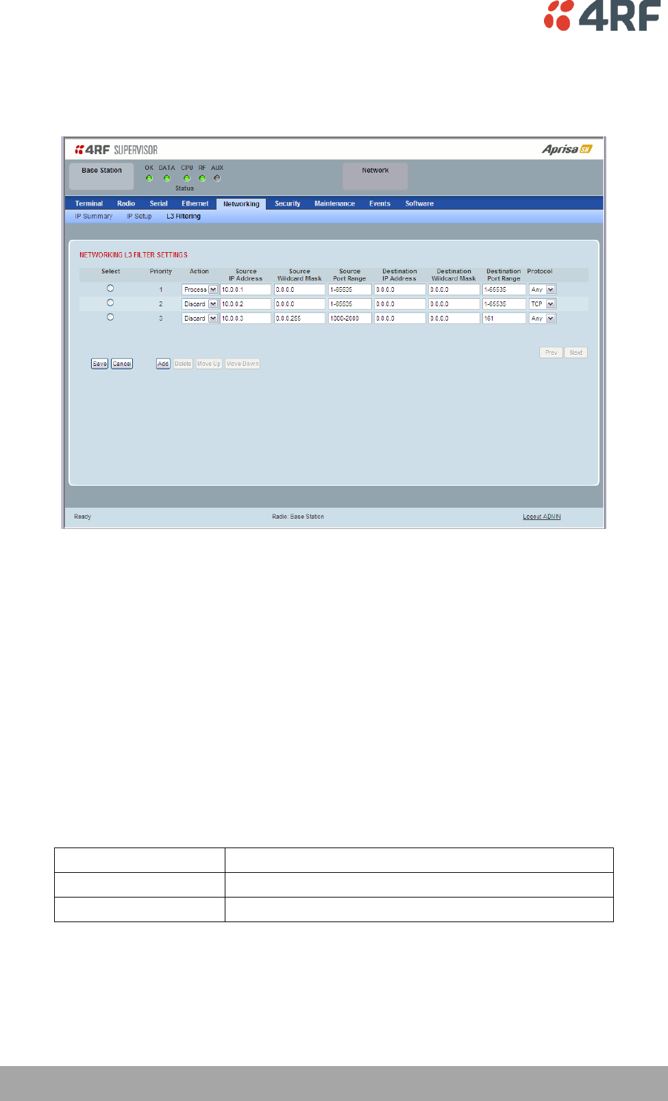
NETWORKING L3 FILTER SETTINGS
L3 Filtering provides the ability to evaluate traffic and take specific action based on the filter criteria.
This filtering can also be used for L4 TCP/UDP port filtering which in most cases relates to specific
applications as per IANA official and unofficial well-known ports.
Entering a * into any to field will automatically enter the wildcard values when the data is saved.
Priority
This parameter shows the priority order in which the filters are processed.
Action
This parameter defines the action taken on the packet when it meets the filter criteria.
Option
Function
Process
Processes the packet if it meets the filter criteria
Discard
Discards the packet if it meets the filter criteria
Source IP Address
If the source IP address is set to 0.0.0.0, any source IP address will meet the filter criteria.

Managing the Radio | 115
Aprisa SR User Manual
Source Wildcard Mask
This parameter defines the mask applied to the Source IP Address. 0 means that it must be a match.
If the Source Wildcard Mask is set to 0.0.0.0, the complete Source IP Address will be evaluated for the
filter criteria.
If the Source Wildcard Mask is set to 0.0.255.255, the first 2 octets of the Source IP Address will be
evaluated for the filter criteria.
If the Source Wildcard Mask is set to 255.255.255.255, none of the Source IP Address will be evaluated for
the filter criteria.
Note: The Source Wildcard Mask operation is the inverse of subnet mask operation
Source Port Range
This parameter defines the port or port range for the source. To specify a range, insert a dash between
the ports e.g 1000-2000. If the Source Port Range is set to 1-65535, traffic from any source port will meet
the filter criteria.
Destination IP Address
This parameter defines the destination IP address of the filter. If the destination IP address is set to
0.0.0.0, any destination IP address will meet the filter criteria.
Destination Wildcard Mask
This parameter defines the mask applied to the Destination IP Address. 0 means that it must be a match.
If the Destination Wildcard Mask is set to 0.0.0.0, the complete Destination IP Address will be evaluated
for the filter criteria.
If the Destination Wildcard Mask is set to 0.0.255.255, the first 2 octets of the Destination IP Address will
be evaluated for the filter criteria.
If the Destination Wildcard Mask is set to 255.255.255.255, none of the Destination IP Address will be
evaluated for the filter criteria.
Note: The Destination Wildcard Mask operation is the inverse of subnet mask operation
Destination Port Range
This parameter defines the port or port range for the destination. To specify a range, insert a dash
between the ports e.g 1000-2000. If the destination port range is set to 1-65535, traffic to any destination
port will meet the filter criteria.
Protocol
This parameter defines the Ethernet packet type that will meet the filter criteria.
Controls
The Delete button deletes the selected entry.
The Move Up button moves the selected entry above the entry above it increasing it’s process priority.
The Move Down button moves the selected entry below the entry above it reducing it’s process priority.
116 | Managing the Radio
Aprisa SR User Manual
Security
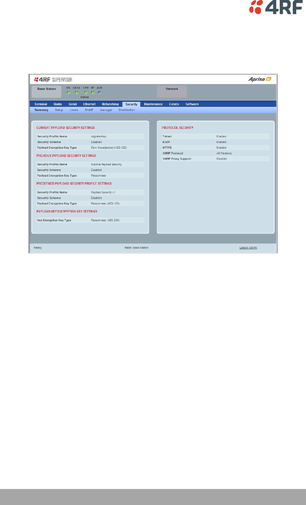
Security > Summary
This page displays the current settings for the Security parameters.
See ‘Security > Setup’ and ‘Security > Manager’ for configuration options.
Managing the Radio | 117
Aprisa SR User Manual
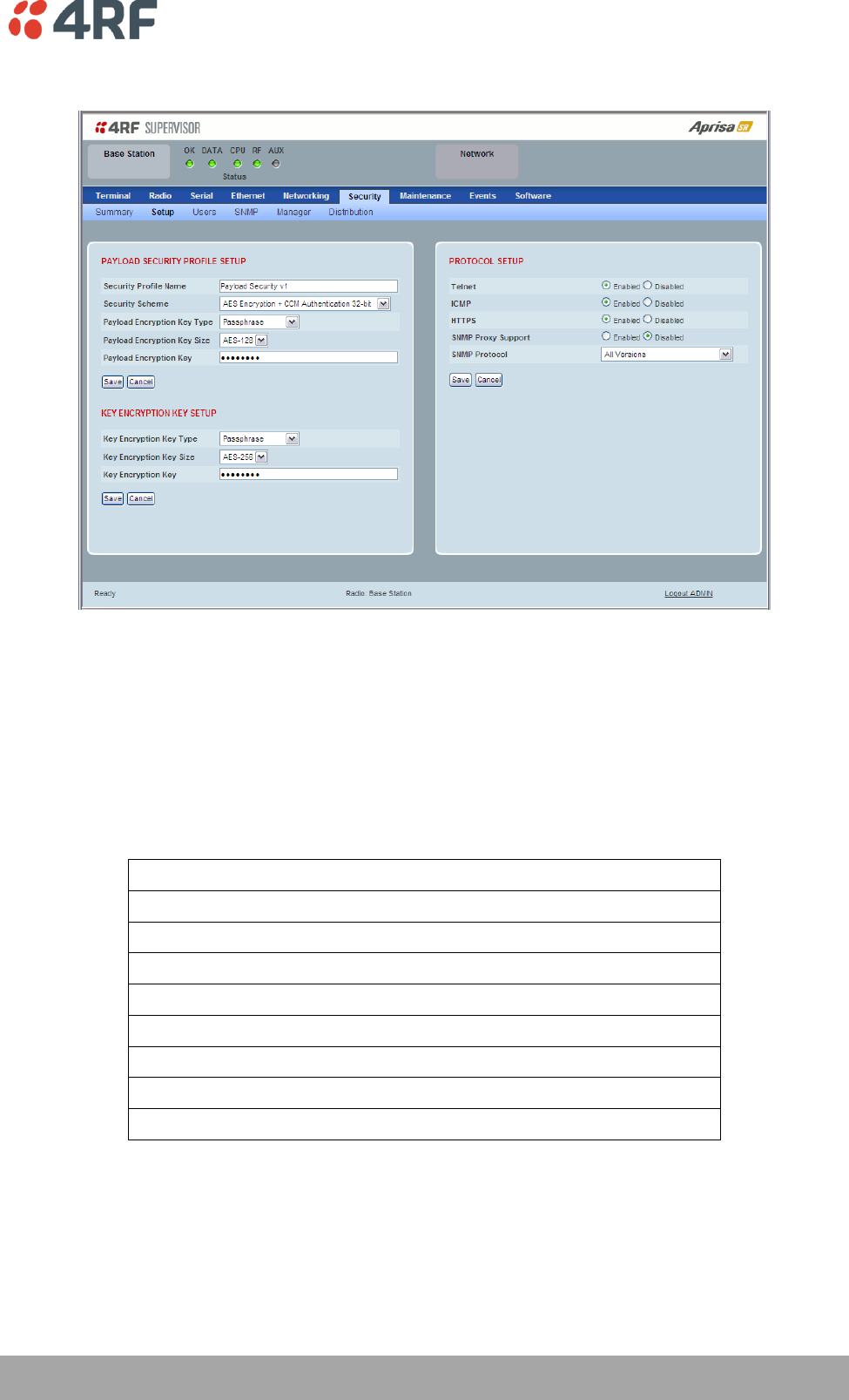
Security > Setup
PAYLOAD SECURITY PROFILE SETUP
Security Profile Name
This parameter enables the user to predefine a security profile with a specified name.
Security Scheme
This parameter sets the security scheme to one of the values in the following table:
Security Level
Disabled (No encryption and no Message Authentication Code)
AES Encryption + CCM Authentication 128 bit
AES Encryption + CCM Authentication 64 bit
AES Encryption + CCM Authentication 32 bit
AES Encryption only
CCM Authentication 128 bit
CCM Authentication 64 bit
CCM Authentication 32 bit
The default setting is Disabled.
118 | Managing the Radio
Aprisa SR User Manual
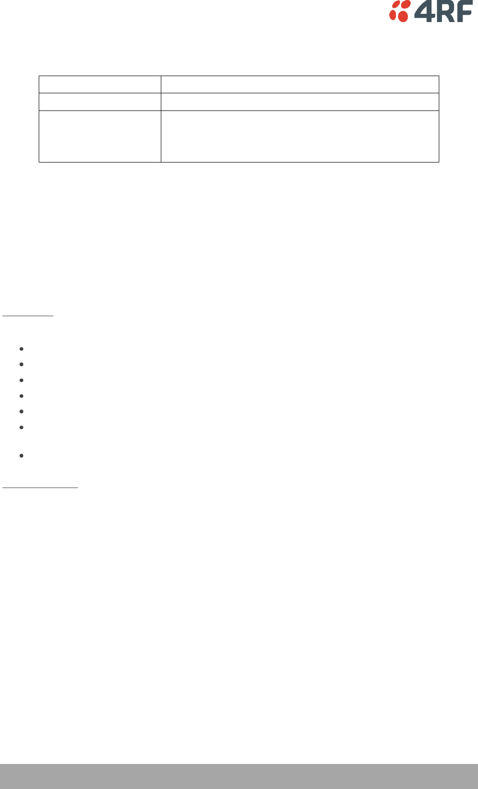
Payload Encryption Key Type
This parameter sets the Payload Encryption Key Type:
Option
Function
Pass Phrase
Use the Pass Phrase password format for standard security.
Raw Hexidecimal
Use the Raw Hexidecimal password format for better
security. It must comply with the specified encryption key
size e.g. if Encryption Type to AES128, the encryption key
must be 16 bytes (32 chars)
The default setting is Pass Phrase.
Payload Encryption Key Size
This parameter sets the Encryption Type to AES128, AES192 or AES256. The default setting is AES128.
The higher the encryption size the better the security.
Payload Encryption Key
This parameter sets the Payload Encryption password. This key is used to encrypt the payload.
Pass Phrase
Good password policy:
contains at least eight characters, and
contains at least one upper case letter, and
contains at least one lower case letter, and
contains at least one digit or another character such as !@#$%^&(){}[]<>... , and
is not a term in a familiar language or jargon, and
is not identical to or derived from the accompanying account name, from personal characteristics
or from information from one’s family/social circle, and
is easy to remember, for instance by means of a key sentence
Raw Hexidecimal
The Raw Hexidecimal password must comply with the specified encryption key size e.g. if Encryption Type
to AES128, the encryption key must be 16 bytes (32 chars).

Managing the Radio | 119
Aprisa SR User Manual
KEY ENCRYPTION KEY SETUP
The Key Encryption Key provides the ability to encrypt the Payload Encryption Key so it can be safely
transmitted over the radio link to remote radios.
The Key Encryption Key Type, Key Encryption Key Size and Key Encryption Key must be the same on all
radios in the network.
Key Encryption Key Type
This parameter sets the Payload Encryption Key Type:
Option
Function
Pass Phrase
Use the Pass Phrase password format for standard security.
Raw Hexidecimal
Use the Raw Hexidecimal password format for better
security. It must comply with the specified encryption key
size
e.g. if Encryption Type to AES128, the encryption key must
be 16 bytes (32 chars)
The default setting is Pass Phrase.
Key Encryption Key Size
This parameter sets the Encryption Type to AES128, AES192 or AES256. The default setting is AES128.
The higher the encryption type the better the security.
Key Encryption Key
This parameter sets the Key Encryption password. This is used to encrypt the payload encryption key.
120 | Managing the Radio
Aprisa SR User Manual
PROTOCOL SETUP
Telnet option
This parameter option determines if you can manage the radio via a Telnet session. The default setting is
disabled.
ICMP option (Internet Control Message Protocol)
This parameter option determines whether the radio will respond to a ping. The default setting is
disabled.
HTTPS option
This parameter option determines if you can manage the radio via a HTTPS session (via a Browser). The
default setting is enabled.
SNMP Proxy Support
This parameter option enables an SNMP proxy server in the base station. This proxy server reduces the
radio link traffic during SNMP communication to remote / repeater stations. This option applies to the
base station only. The default setting is disabled.
This option can also be used if the radio has Serial Only interfaces.
SNMP Protocol
This parameter sets the SNMP Protocol:
Option
Function
Disabled
All SNMP functions are disabled.
All Versions
Allows all SNMP protocol versions.
SNMPv3 Only
Only SNMPv3 transactions will be accepted.
SNMPv3 With
Authentication Only
Only SNMPv3 transactions authenticated using HMAC-MD5 or
HMAC-SHA will be accepted.
The default setting is All Versions.
The default SNMPv3 with Authentication User Details provided are:
User Name
Authentication
Type
Context Name
Authentication
Passphrase
noAuthUser
-
noAuth
noAuthUser
authUserMD5
MD5
auth
authUserMD5
authUserSHA
SHA
auth
authUserSHA

Managing the Radio | 121
Aprisa SR User Manual
SNMPv3 Authentication Passphrase
The Authentication Passphrases can be changed via SNMP (not SuperVisor).
When viewing / managing the details of the users via SNMP, the standard SNMP-USER-BASED-SM-MIB
interface is used. This interface can be used to change the Authentication Passphrase of the users.
The Authentication Passphrase of the user required to be changed cannot be changed by the same user i.e
a different user must be used for the transactions.
To change a user authentication passphrase:
1. SET the usmUserStatus object for that user to ‘Not In Service’
2. GET the usmUserSpinLockobject
3. SET the usmUserSpinLockobject with the value that was just GOT in the previous step
4. SET the usmUserAuthKeyChange to the new Authentication key string
5. SET the usmUserPrivKeyChangeto the new Privacy key string
6. SET the usmUserStatus object for that user to ‘Active’
Note that the key string for steps 4 and 5 are 32 octet hexadecimal values. This string is generated based
on the ‘old passphrase’ and ‘new passphrase’ as specified in RFC2274.
The utility ‘encode_keychange.exe’, available from NET-SNMP open source applications, can be used to
generate this string.
An example command to generate a new Authentication key string for the default desUserMD5 is:
encode_keychange –t md5 –O “desUserMD5” –N “desUserMD5Auth” –E 0x0100DC
An example command to generate a new Privacy key string for the default desUserMD5 is:
encode_keychange –t md5 –O “desUserMD5” –N “desUserMD5Priv” –E 0x0100DC
These command executions will return a 32 Octet Hexadecimal string that can be used in steps 4 and 5
above.
122 | Managing the Radio
Aprisa SR User Manual
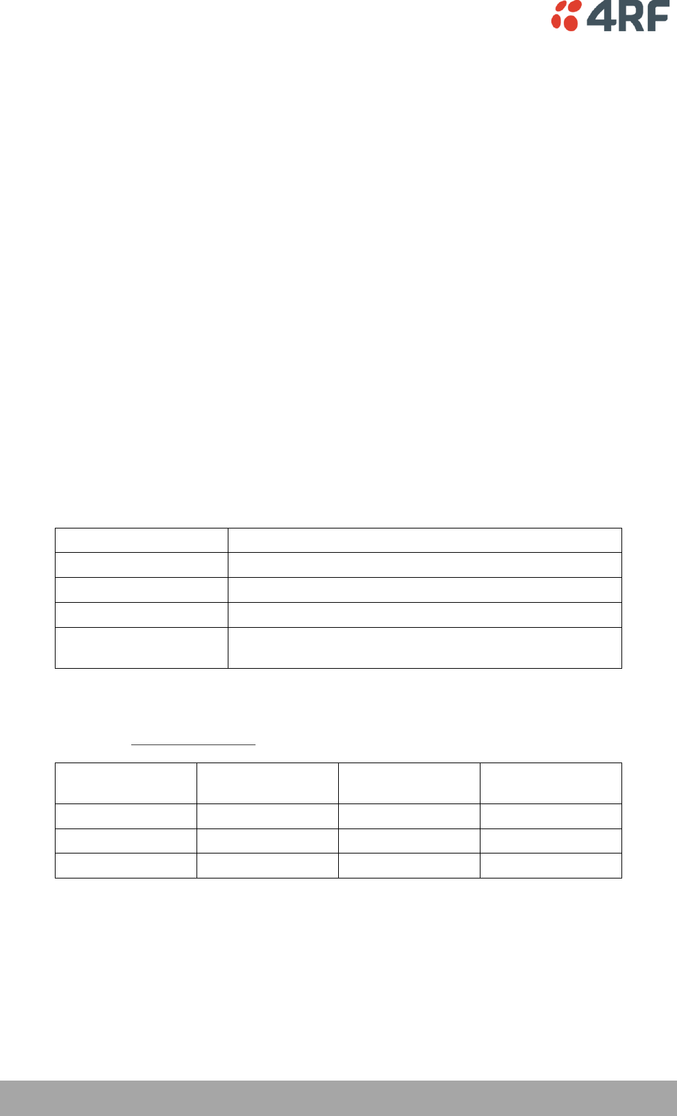
Security > Users
Note: You must login with ‘admin’ privileges to add, disable, delete a user or change a password.
USER DETAILS
Shows a list of the current users setup in the radio.
ADD NEW USER
To add a new user:
1. Enter the Username.
A username can be up to 32 characters but cannot contain back slashes, forward slashes, spaces, tabs,
single or double quotes. Usernames are case sensitive.
2. Enter the Password.
A password can be 8 to 32 characters but cannot contain back slashes, forward slashes, spaces, tabs,
single or double quotes. Passwords are case sensitive.
Good password policy:
contains at least eight characters, and
contains at least one upper case letter, and
contains at least one lower case letter, and
contains at least one digit or another character such as !@#$%^&(){}[]<>... , and
is not a term in a familiar language or jargon, and
is not identical to or derived from the accompanying account name, from personal characteristics
or from information from one’s family/social circle, and
is easy to remember, for instance by means of a key sentence

Managing the Radio | 123
Aprisa SR User Manual
3. Select the User Privileges
There are four pre-defined User Privilege settings to allocate access rights to users. These user privileges
have associated default usernames and passwords of the same name.
The default login is ‘admin’.
This login has full access to all radio parameters including the ability to add and change users. There can
only be a maximum of two usernames with admin privileges and the last username with admin privileges
cannot be deleted.
User
Privilege
Default
Username
Default
Password
User Privileges
View
view
view
Users in this group can only view the summary
pages.
Technician
technician
technician
Users in this group can view and edit parameters
except Security > Users, Security > Settings and
Advanced settings.
Engineer
engineer
engineer
Users in this group can view and edit parameters
except Security > Users.
Admin
admin
admin
Users in this group can view and edit all
parameters.
See ‘SuperVisor Menu Access’ on page 76 for the list of SuperVisor menu items versus user privileges.
4. Click ‘Add’
To delete a user:
1. Select Terminal Settings > Security > Users
2. Click on the Select button for the user you wish to delete.
3. Click ‘Delete
To change a Password:
1. Select Terminal Settings > Security > Users
2. Click on the Select button for the user you wish to change the Password.
3. Enter the Password.
A password can be 8 to 32 characters but cannot contain back slashes, forward slashes, spaces, tabs,
single or double quotes.
124 | Managing the Radio
Aprisa SR User Manual
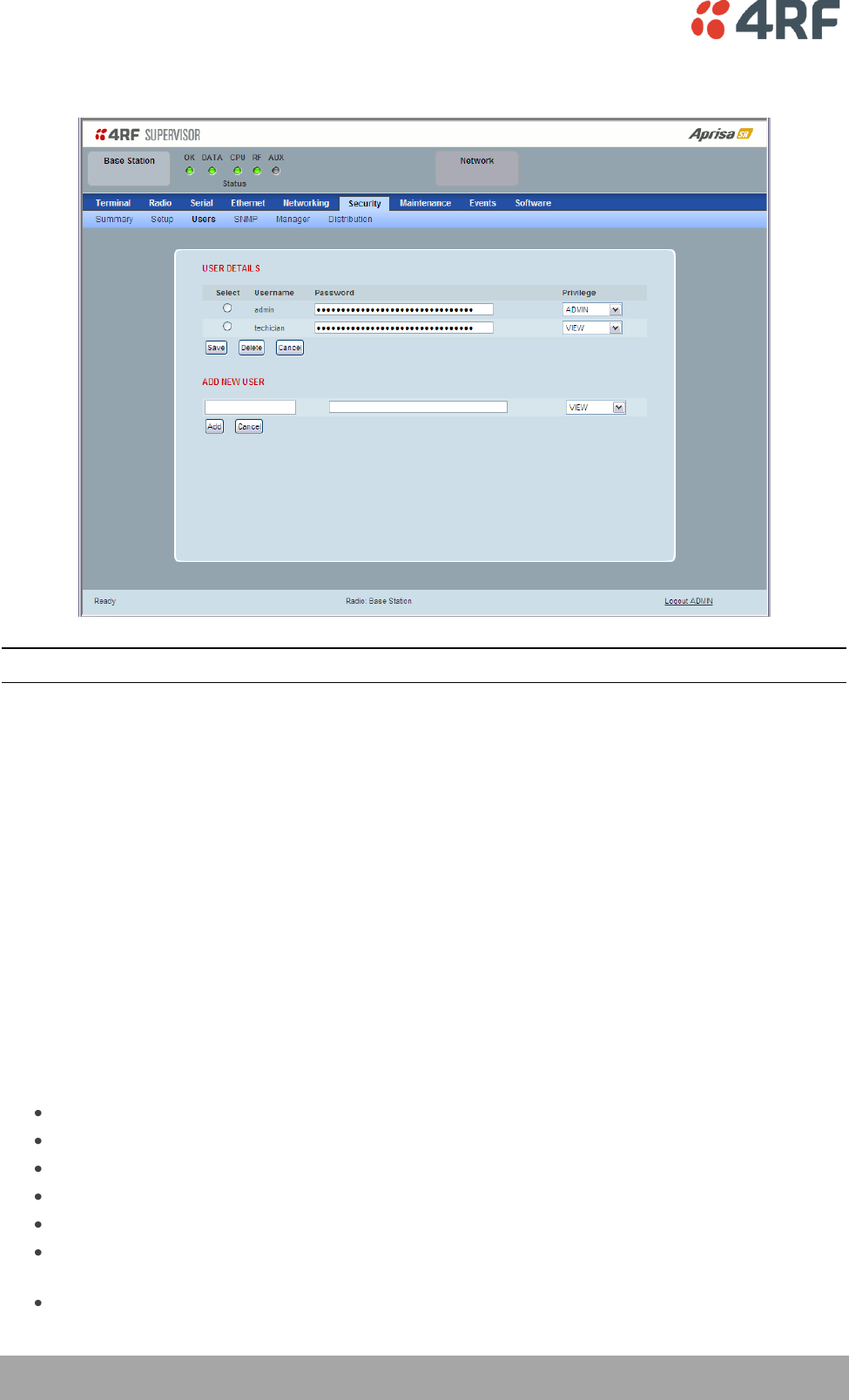
Security > SNMP
In addition to web-based management (SuperVisor), the network can also be managed using the Simple
Network Management Protocol (SNMP). MIB files are supplied, and these can be used by a dedicated SNMP
Manager, such as Castle Rock’s SNMPc, to access most of the radio’s configurable parameters.
For communication between the SNMP manager and the radio, Access Controls and Community strings
must be set up as described in the following sections.
A SNMP Community String is used to protect against unauthorized access (similar to a password). The
SNMP agent (radio or SNMP manager) will check the community string before performing the task
requested in the SNMP message.
ACCESS CONTROL SETUP
A SNMP Access Control is the IP address of the radio used by an SNMP manager or any other SNMP device
to access the radio. The Aprisa SR allows access to the radio from any IP address.
Read Only
The default Read Only community string is public.
Read Write
The default ReadWrite community string is private.

Managing the Radio | 125
Aprisa SR User Manual
SNMP Manager Setup
The SNMP manager community strings must be setup to access the base station and remote / repeater
stations.
To access the base station, a community string must be setup on the SNMP manager the same as the
community string setup on the radio (see ‘Security > SNMP’ on page 124).
SNMP access to remote / repeater stations can be achieved by using the radio’s IP address and the normal
community string or by proxy in the base station.
SNMP Access via Base Station Proxy
To access the remote / repeater stations via the base station proxy, the community strings must be setup
on the SNMP manager in the format:
ccccccccc:bbbbbb
Where:
ccccccccc is the community string of the base station
and
bbbbbb is the last 3 bytes of the remote station MAC address (see ‘Network Status > Network Table’
on page 167) for the remote station MAC address.
The SNMP Proxy Support must be enabled for this method of SNMP access to operate (see ‘SNMP Proxy
Support’ on page 120).
126 | Managing the Radio
Aprisa SR User Manual
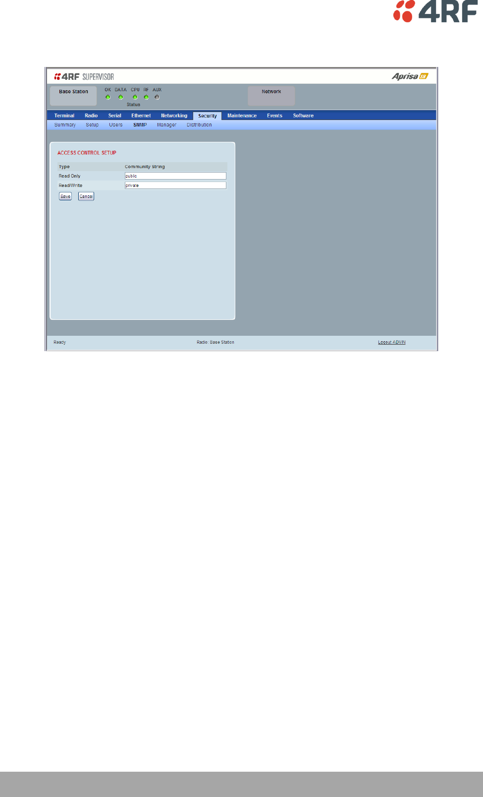
Security > Manager
CURRENT PAYLOAD SECURITY PROFILE
Profile Name
This parameter shows the predefined security profile active on the radio.
Status
This parameter displays the status of the predefined security profile on the radio (always active).
PREVIOUS PAYLOAD SECURITY PROFILE
Profile Name
This parameter displays the security profile that was active on the radio prior to the current profile being
activated.
Status
This parameter displays the status of the security profile that was active on the radio prior to the current
profile being activated.
Option
Function
Active
The security profile is active on the radio.
Inactive
The security profile is not active on the radio but could be
activated if required.

Managing the Radio | 127
Aprisa SR User Manual
Activate
This parameter activates the previous security profile (restores to previous version).
PREDEFINED PAYLOAD SECURITY PROFILE
Profile Name
This parameter displays the new security profile that could be activated on the radio or distributed to all
remote radios with Security > Distribution.
Status
This parameter displays the status of the new security profile.
Option
Function
Unavailable
A predefined security profile is not available on this radio.
To create a predefined security profile, go to ‘Security > Setup’ on
page 117.
Available
A predefined security profile is available on this radio for
distribution and activation.
128 | Managing the Radio
Aprisa SR User Manual
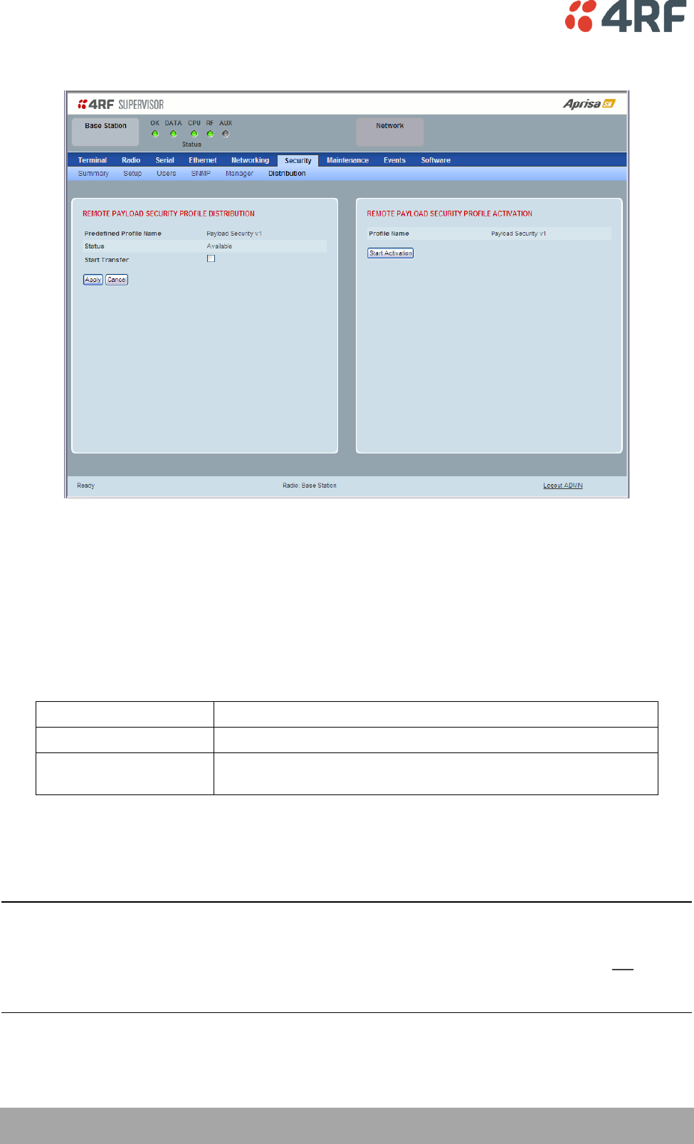
Security > Distribution
REMOTE PAYLOAD SECURITY PROFILE DISTRIBUTION
Predefined Profile Name
This parameter displays the predefined security profile available for distribution to remote stations.
Status
This parameter shows if a predefined security profile is available for distribution to remote stations.
Option
Function
Unavailable
A predefined payload security profile is not available on this radio.
Available
A predefined payload security profile is available on this radio for
distribution and activation.
Start Transfer
This parameter when activated distributes (broadcasts) the new payload security profile to all remote
stations in the network.
Note: The distribution of the payload security profile to remote stations does not stop customer traffic
from being transferred.
Payload security profile distribution traffic is classified as ‘management traffic’ but does not use the
Ethernet management priority setting. Security profile distribution traffic priority has a fixed priority
setting of ‘very low’.
Managing the Radio | 129
Aprisa SR User Manual
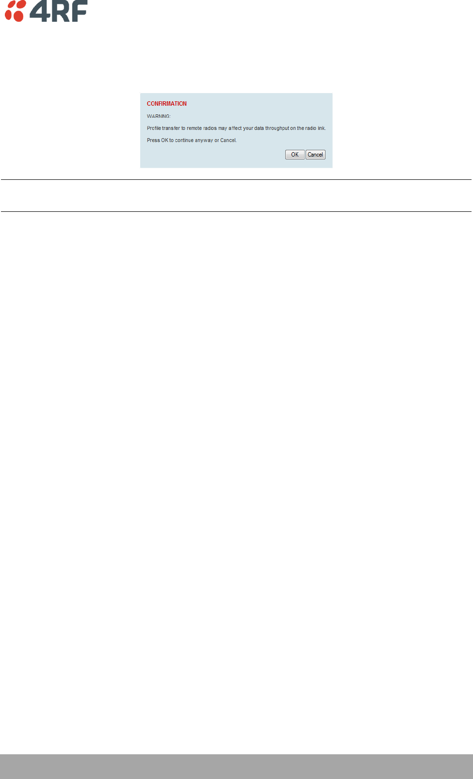
To distribute the payload security profile to remote stations:
This process assumes that a payload security profile has been setup (see ‘Security > Setup’ on page 117).
1. Tick Start Transfer and click Apply.
Note: This process could take up to 1 minute per radio depending on channel size, Ethernet Management
Priority setting and the amount of customer traffic on the network.
2. When the distribution is completed, activate the software with the Remote Payload Security Profile
Activation.
130 | Managing the Radio
Aprisa SR User Manual
REMOTE PAYLOAD SECURITY PROFILE ACTIVATION
When the security profile has been distributed to all the remote stations, the security profile is then
activated in all the remote stations with this command.
Predefined Profile Name
This parameter displays the predefined security profile available for activation on all remote stations.
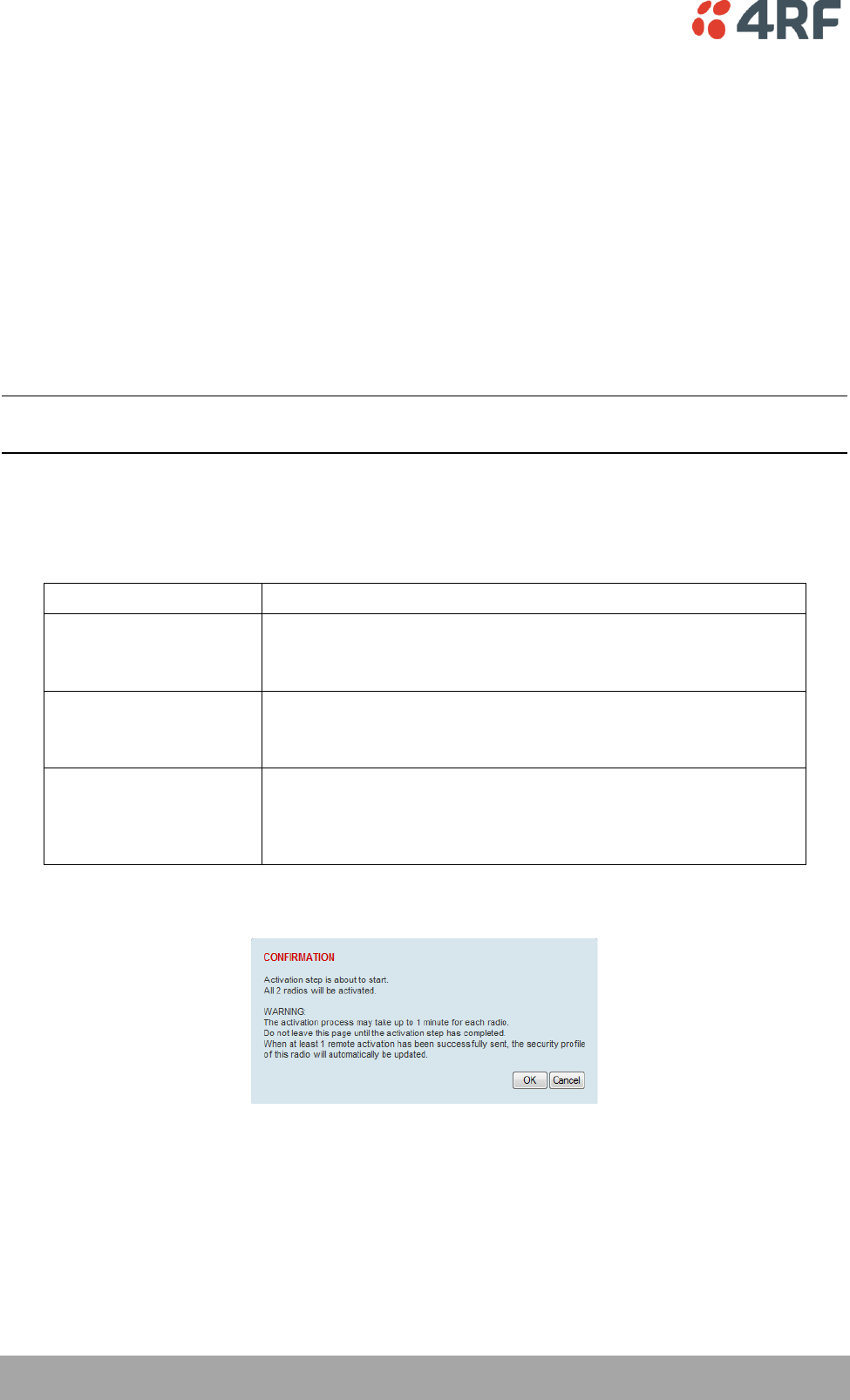
To activate the security profile in remote stations:
This process assumes that a security profile has been setup into the base station (see ‘Security > Setup’ on
page 117) and distributed to all remote radios in the network.
Note: Do not navigate SuperVisor away from this page during the activation process (SuperVisor can lose
PC focus).
1. Click Start Activation
The remote stations will be polled to determine which radios require activation:
Result
Function (X of Y)
Remote Radios Polled for
New Profile
X is the number of radios polled to determine if the radio contains
the new security profile.
Y is the number of remote radios registered with the base station.
Remote Radios Activated
X is the number of radios activated.
Y is the number of radios with the new security profile requiring
activation.
Remote Radios On New
Profile
X is the number of radios activated and on the new security
profile.
Y is the number of radios with the new security profile that have
been activated.
When the activation is ready to start:
3. Click on ‘OK’ to start the activation process or Cancel to quit.
Managing the Radio | 131
Aprisa SR User Manual
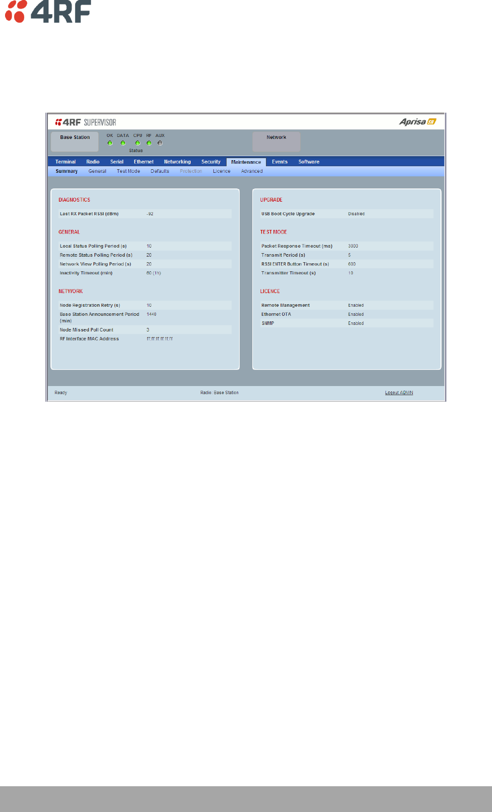
Maintenance
Maintenance > Summary
This page displays the current settings for the Maintenance parameters.
DIAGNOSTICS
Last RX Packet RSSI (dBm)
This parameter displays the receiver RSSI reading taken from the last data packet received.
GENERAL
Local Status Polling Period (sec)
This parameter displays the rate at which SuperVisor refreshes the Local Radio alarm LED states and RSSI
value.
Remote Status Polling Period (sec)
This parameter displays the rate at which SuperVisor refreshes the Remote Radio alarm LED states and
RSSI value.
Inactivity Timeout (min)
This parameter displays the period of user inactivity before SuperVisor automatically logs out of the radio.

132 | Managing the Radio
Aprisa SR User Manual
NETWORK
Node Registration Retry (sec)
This parameter displays the base station poll time at startup or the remote / repeater station time
between retries until registered.
Base Station Announcement Period (min)
This parameter displays the period between base station polls post startup. The default setting is 1440
minutes (24 hours).
Node Missed Poll Count
This parameter displays the number of times the base station attempts to poll the network at startup or if
a duplicate IP is detected when a remote / repeater station is replaced.
RF Interface MAC address
This parameter displays the RF Interface MAC address when the radio is part of a Protected Station.
UPGRADE
USB Boot Cycle Upgrade
This parameter shows the type of USB Boot Cycle upgrade defined in ‘Software Setup > USB Boot Upgrade’
on page 155.
TEST MODE
Packet Response Timeout (ms)
This parameter displays the time Test Mode waits for a response from the base station before it times out
and retries.
Transmit Period (sec)
This parameter displays the time between Test Mode requests to the base station.
Response Timeout (ms)
This parameter sets the time Test Mode waits for a response from the base station before it times out and
retries. The default setting is 3000 ms.
RSSI Enter Button Timeout (sec)
This parameter displays the Test Mode timeout period. The radio will automatically exit Test Mode after
the Timeout period.
Transmitter Timeout (sec)
This parameter displays the transmitter Test Mode timeout period. The radio will automatically exit the
transmitter Test Mode after the Timeout period.

Managing the Radio | 133
Aprisa SR User Manual
LICENCE
Remote Management
This parameter displays if Remote Management is enabled or disabled. The default setting is enabled.
Ethernet OTA (over the air)
This parameter displays if Ethernet traffic is enabled or disabled. The Ethernet OTA will be enabled if the
Ethernet feature licence has been purchased (see ‘Maintenance > Licence’ on page 140).
SNMP Management
This parameter displays if SNMP management is enabled or disabled. The default setting is enabled.
134 | Managing the Radio
Aprisa SR User Manual
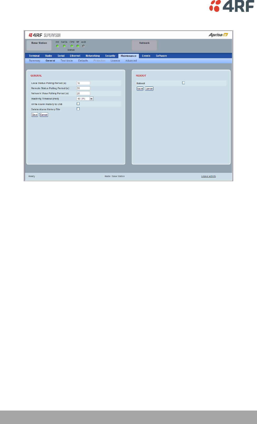
Maintenance > General
GENERAL
Local Status Polling Period (sec)
This parameter sets the rate at which SuperVisor refreshes the Local Radio alarm LED states and RSSI
value. The default setting is 10 seconds.
Network View Polling Period (sec)
This parameter sets the rate at which SuperVisor polls all remote radios for status and alarm reporting.
The default setting is 20 seconds.
Remote Status Polling Period (sec)
This parameter sets the rate at which SuperVisor refreshes the Remote Radio alarm LED states and RSSI
value. To avoid problems when managing Aprisa SR Networks, ensure that the Remote Polling Period is set
to be longer than the Inband Management Timeout (set on page 82). The default setting is 20 seconds.
Inactivity Timeout (min)
This parameter sets the period of user inactivity before SuperVisor automatically logs out of the radio. The
default setting is 15 minutes.
Managing the Radio | 135
Aprisa SR User Manual
Write Alarm History to USB
This parameter when enabled writes the alarm history file to a USB flash drive into the Host Port .
The file is a space delimited text file with a file name in the format ‘alarm_ipaddress_date,time’
e.g. ‘alarm_172.17.10.17_2000-01-13,17.13.45.txt’.
The maximum number of event entries that can be stored is 1500 alarms.
The following table is an example of the alarm history file generated:
Index
Event Name
Severity
State
Time
Additional Information
1
softwareStartUp
information
0
2011-05-08,12:26:31.0
Power on Reset
2
softwareStartUp
information
0
2011-05-08,12:56:33.0
Power on Reset
3
protPeerCommunicationsLost
major
1
2011-05-08,12:56:39.0
Ethernet Comm Lost with Peer
4
protSwitchOccurred
information
0
2011-05-08,12:56:39.0
Keepalive missed from Active
5
protPeerCommunicationsLost
cleared
2
2011-05-08,12:56:40.0
Alarm Cleared
6
rfNoReceiveData
warning
1
2011-05-08,12:56:53.0
RF No Rx Data for 6 seconds
7
eth2NoRxData
warning
1
2011-05-08,12:57:03.0
ETH2 has not received data for 21
seconds
8
rfNoReceiveData
cleared
2
2011-05-08,12:57:05.0
9
rfNoReceiveData
warning
3
2011-05-08,12:57:12.0
RF No Rx Data for 6 seconds
10
rfNoReceiveData
cleared
4
2011-05-08,12:57:23.0
11
serialNoRxData
warning
1
2011-05-08,12:57:25.0
Serial has not received data for 44
seconds
12
rfNoReceiveData
warning
5
2011-05-08,12:57:29.0
RF No Rx Data for 6 seconds
13
rfNoReceiveData
cleared
6
2011-05-08,12:57:59.0
State
The State column is an indication of whether the event is active or not. An even number indicates an
inactive state while an odd number indicates an active state.
The AUX LED will flash orange while the file is copying to the USB flash drive.
Delete Alarm History file
This parameter when activated deletes the alarm history file stored in the radio.
136 | Managing the Radio
Aprisa SR User Manual
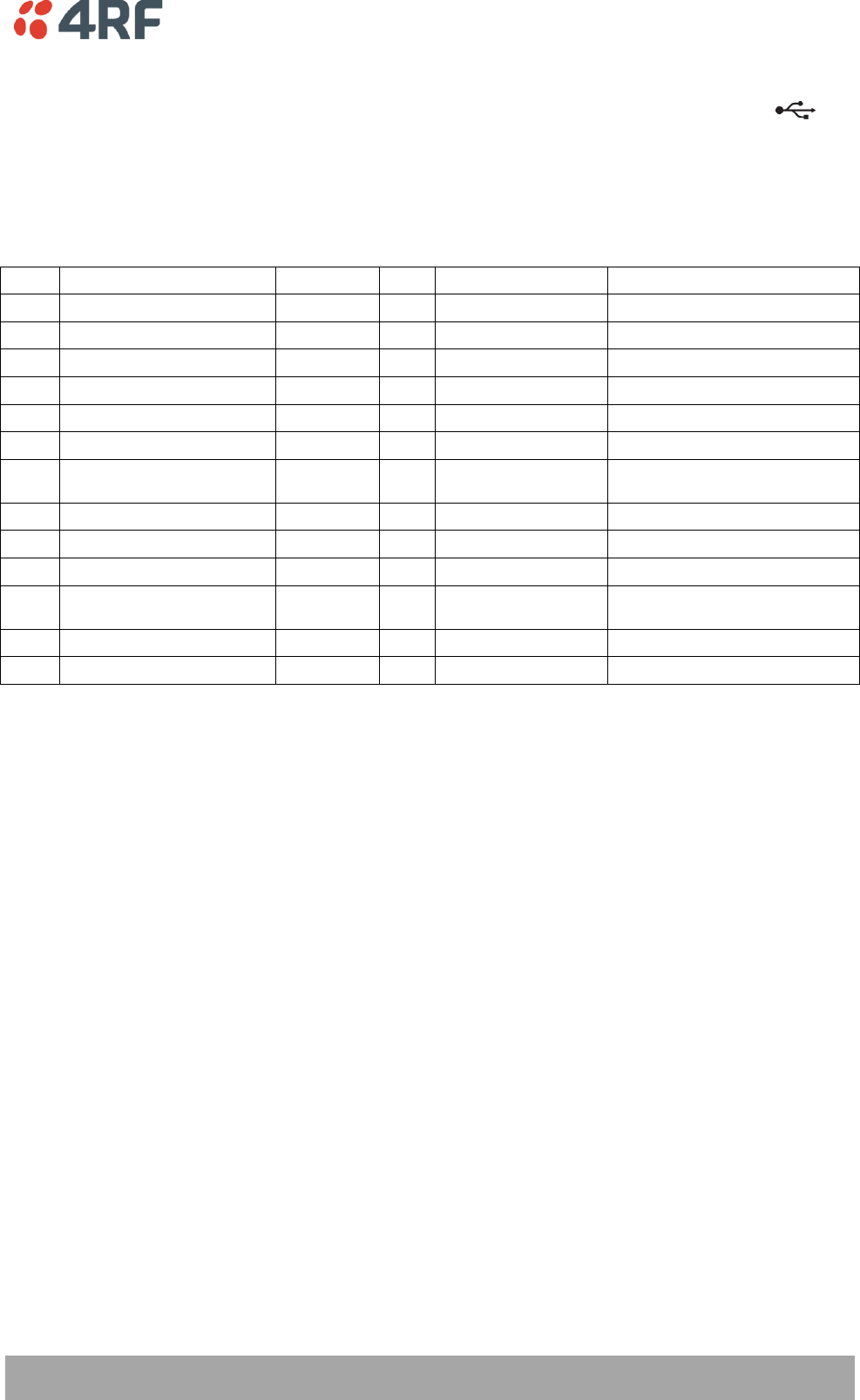
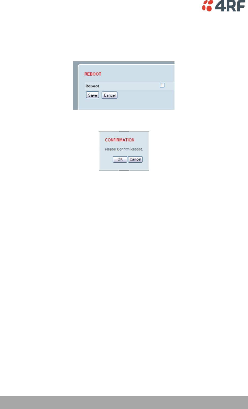
REBOOT
To reboot the radio:
1. Select Maintenance > General.
2. Tick the ‘Reboot’ checkbox.
3. Click ‘Save’ to apply the changes or ‘Cancel’ to restore the current value.
4. Click ‘OK’ to reboot the radio or ‘Cancel’ to abort.
All the radio LEDS will flash repeatedly for 1 second.
The radio will be operational again in about 10 seconds.
The OK, DATA, and CPU LEDS will light green and the RF LED will be green if the network is operating
correctly.
5. Login to SuperVisor.
Managing the Radio | 137
Aprisa SR User Manual
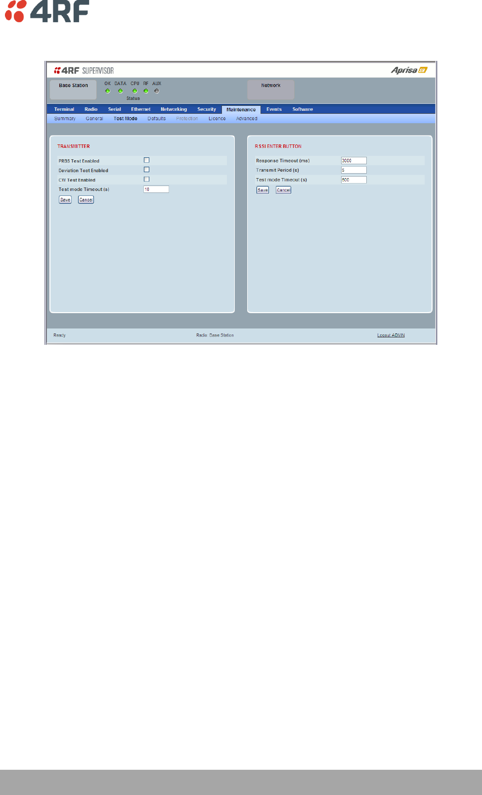
Maintenance > Test Mode
TRANSMITTER
PRBS Test Enabled
When active, the transmitter outputs a continuous PRBS signal. This can be used for evaluating the output
spectrum of the transmitter and verifying adjacent channel power and spurious emission products.
Deviation Test Enabled
When active, the transmitter outputs a sideband tone at the deviation frequency used by the CPFSK
modulator. This can be used to evaluate the local oscillator leakage and sideband rejection performance
of the transmitter.
CW Test Enabled
When active, the transmitter outputs a continuous wave signal. This can be used to verify the frequency
stability of the transmitter.
Test Mode Timeout (s)
This parameter sets the Transmitter Test Mode timeout period. The radio will automatically exit
Transmitter Test Mode after the Timeout period. The default setting is 10 seconds.

138 | Managing the Radio
Aprisa SR User Manual
RSSI ENTER BUTTON
Response Timeout (ms)
This parameter sets the time RSSI Test Mode waits for a response from the base station before it times out
and retries. The default setting is 3000 ms.
Transmit Period (sec)
This parameter sets the time between RSSI Test Mode requests to the base station. The default setting is
5 seconds.
Test Mode Timeout (s)
This parameter sets the RSSI Test Mode timeout period. The radio will automatically exit RSSI Test Mode
after the Timeout period. The default setting is 600 seconds.
Managing the Radio | 139
Aprisa SR User Manual
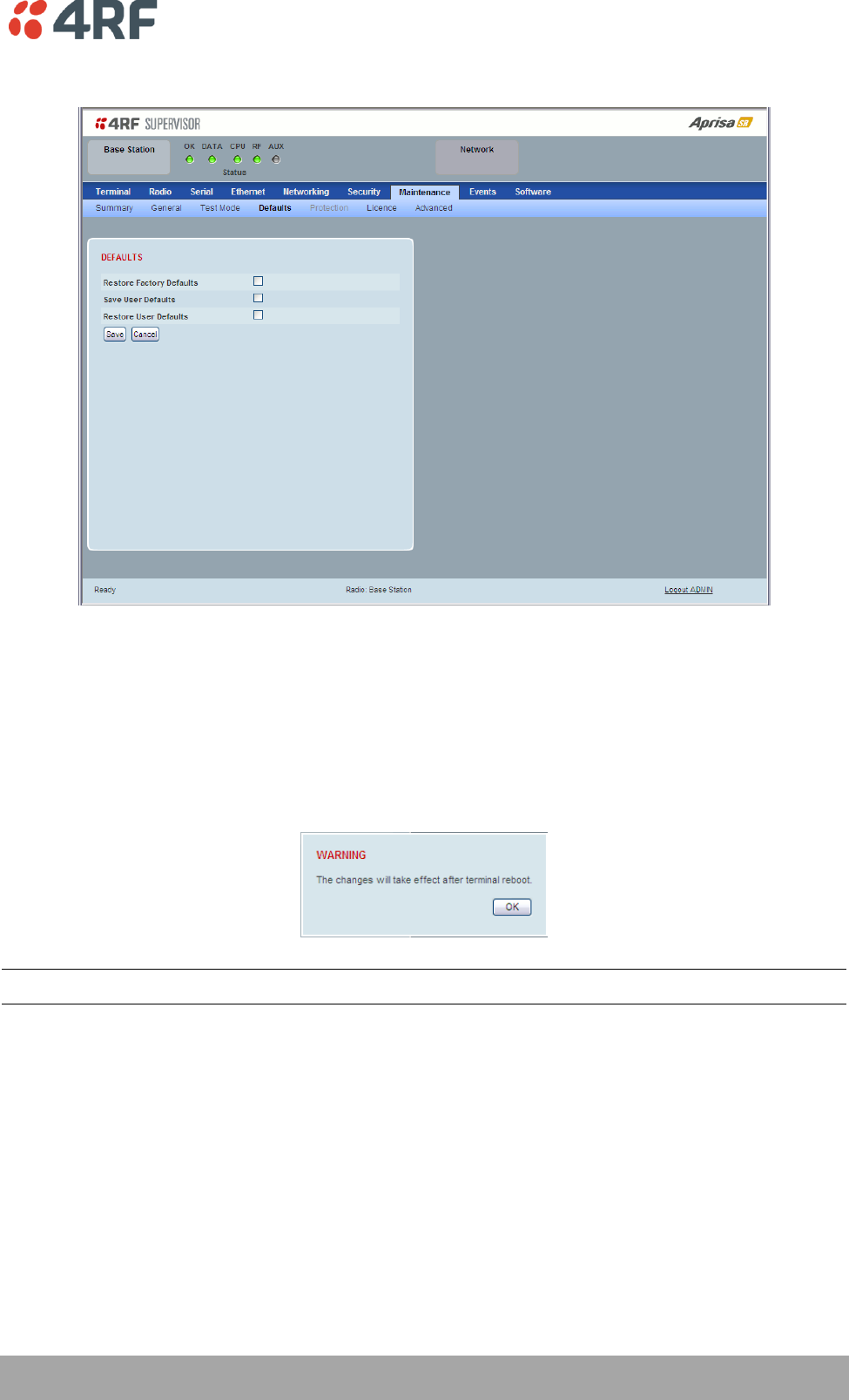
Maintenance > Defaults
DEFAULTS
The Maintenance Defaults page is only available for the local terminal.
Restore Factory Defaults
When activated, all radio parameters will be set to the factory default values. This includes resetting the
radio IP address to the default of 169.254.50.10.
Note: Take care using this command.
Save User Defaults
When activated, all current radio parameter settings will be saved to non-volatile memory within the
radio.
Restore User Defaults
When activated, all radio parameters will be set to the settings previously saved using ‘Save User
Defaults’.
140 | Managing the Radio
Aprisa SR User Manual
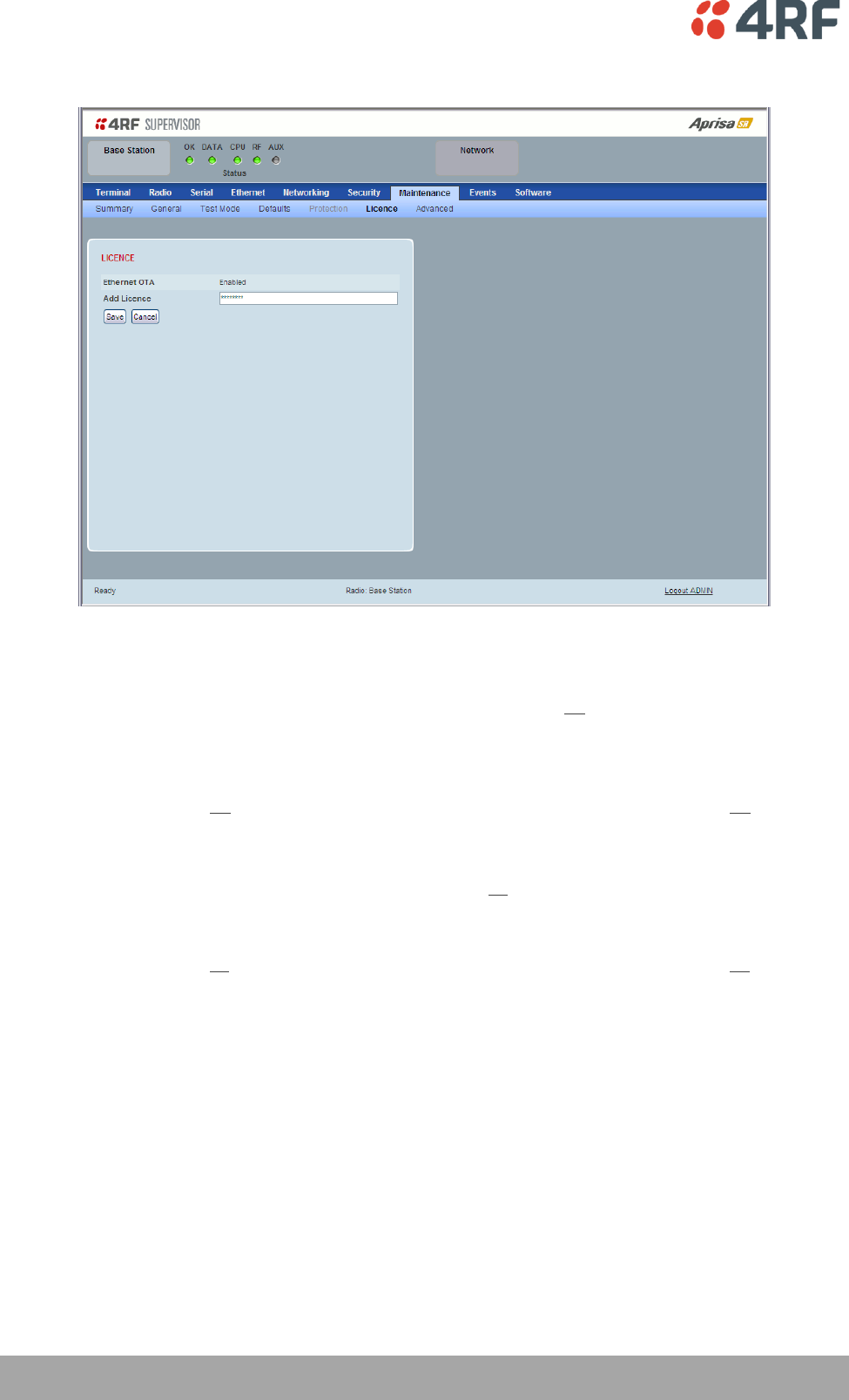
Maintenance > Licence
LICENCE
Fully Featured Radio
When a fully featured Aprisa SR radio is purchased (indicated by the AA), it contains the licences which
activate Remote Management, Ethernet Traffic, and SNMP Management e.g.
Part Number
Part Description
APSR-N400-012-SO-12-ETAA
4RF Aprisa SR, BR, 400-470 MHz, 12.5 kHz, SO, 12 VDC, ET, AA
Serial Only Radio
If a Serial Only Aprisa SR radio is purchased (indicated by the A1), Ethernet Traffic is not enabled.
Part Number
Part Description
APSR-N400-012-SO-12-ETA1
4RF Aprisa SR, BR, 400-470 MHz, 12.5 kHz, SO, 12 VDC, ET, A1
Feature Licences
Feature Licences can be purchased to enable features if they were not purchased initially.
One license key is required per feature and per radio serial number.
Part Number
Part Description
APSA-LSRF-FET
4RF Aprisa SR Acc, Licence, Feature, Ethernet Traffic
When Ethernet traffic is enabled, the Ethernet port status must be set to enabled to allow Ethernet data
communication over the radio link (see ‘Ethernet > Port Setup’ on page 108).
In this software version, Remote Management and SNMP management are enabled by default.
Managing the Radio | 141
Aprisa SR User Manual
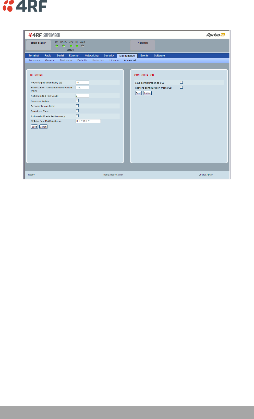
Maintenance > Advanced
NETWORK
Node Registration Retry (sec)
This parameter sets the base station poll time at startup or the remote / repeater station time between
retries until registered. The default setting is 10 seconds.
Base Station Announcement Period (min)
This parameter sets the period between base station polls post startup. The default setting is 1440
minutes (24 hours).
When a new base station powers on, it announces its presence and each remote that receives the
announcement message will be advised that a new base station is present and that they should re-register.
This allows the new base station to populate its Network Table, with knowledge of the nodes in the
network.
If, during this initial period, there is some temporary path disturbance to one or more remotes, they may
miss the initial announcement messages and be left unaware of the base station change. For this reason,
the base station must periodically send out announcement messages to pick up any stray nodes and the
period of these messages is the base station Announcement Period.
Setting this parameter to 0 will stop periodic announcement messages being transmitted.
If a critical parameter is changed in the base station, such as IP address, then the change is distributed to
the network using base station announcement message. Note that in this case, an announcement is sent
immediately independent of the Announcement Period setting.
142 | Managing the Radio
Aprisa SR User Manual
Node Missed Poll Count
This parameter sets the number of times the base station attempts to poll the network at startup or if a
duplicate IP is detected when a remote / repeater station is replaced. The default setting is 3.
Discover Nodes
This parameter when activated triggers the base station to poll the network with Node Missed Poll Count
and Node Registration Retry values.
Decommission Node
This parameter when activated resets the network registrations to remove the entire network from
service.
Note: Take care using this option.
Broadcast Time
This parameter when activated sends the base station Date / Time setting to all the remote and repeater
stations in the network and sets their Date / Time. This option applies to the base station only.
Automatic Route Rediscovery
This parameter enables the radio to transmit route discovery messages when packets are unacknowledged.
When enabled, unacknowledged unicast packets are converted into uni-broadcast messages and sent
through the network. All nodes see the message and populate their routing tables accordingly.
When the destination node is reached, it sends a route response message via the shortest path. The
intermediate nodes see this message and populate their routing tables in the reverse direction, thus re-
establishing the route.
The default setting is disabled.
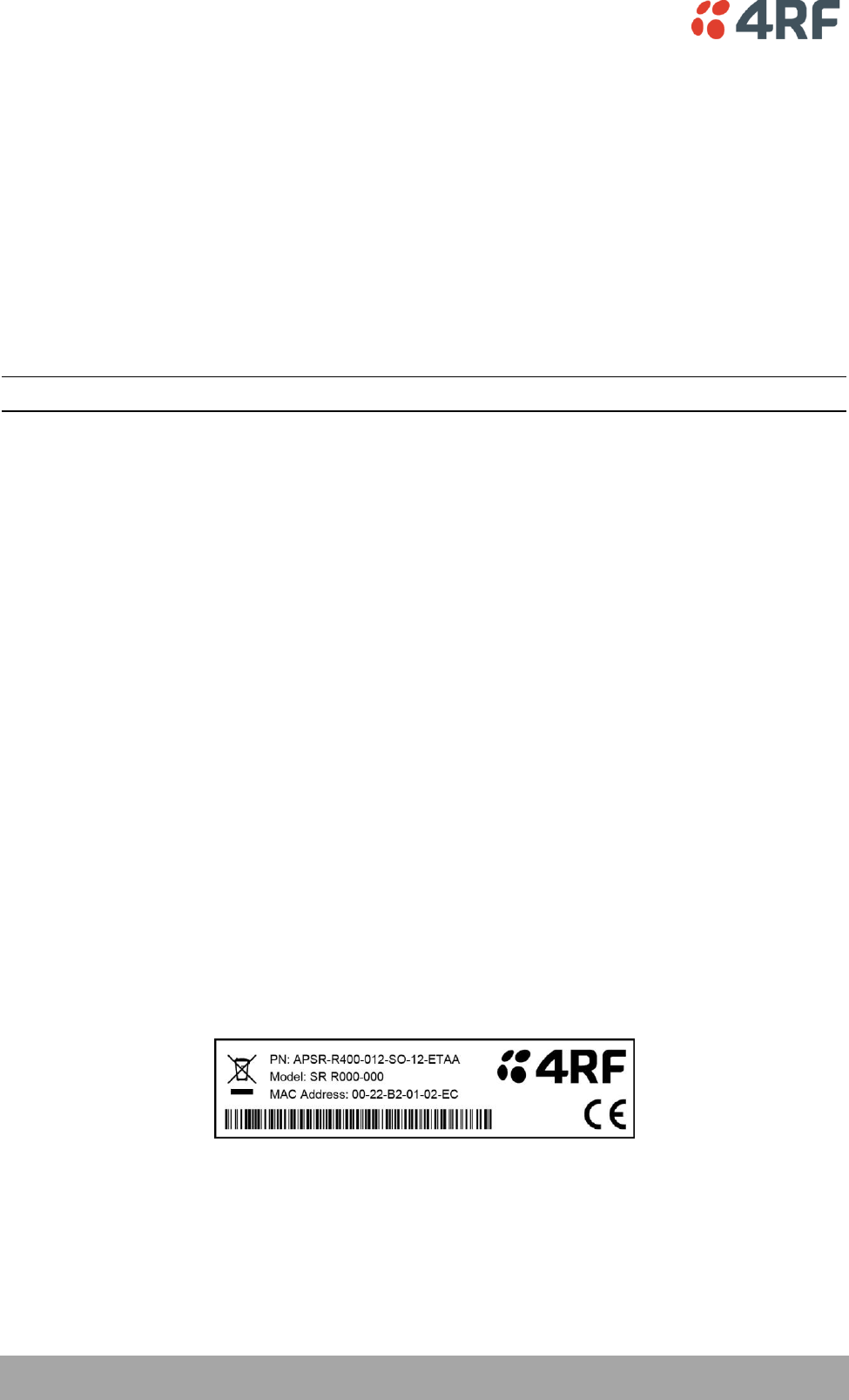
RF Interface MAC address
This parameter is only applicable when the radio is part of a Protected Station.
This RF Interface MAC address is used to define the MAC address of the Protection Switch. This address is
entered into both Protected Station radios in the factory.
If a replacement Protection Switch is installed, the replacement unit MAC address must be entered in both
radios (see ‘Replacing a Faulty Protection Switch’ on page 37).
The Protection Switch RF Interface MAC address is shown on the Protection Switch label:

Managing the Radio | 143
Aprisa SR User Manual
CONFIGURATION
Save Configuration to USB
This parameter saves all user configuration settings to a binary encrypted file on the USB root directory
with filename of asrcfg_1.6.2. Some parameters are not saved e.g. security passwords, licence keys etc.
Restore Configuration from USB
This parameter restores all user configuration settings from a binary encrypted file on the USB root
directory with filename of asrcfg_1.6.2.
Note: Activating this function will over-write all existing configuration settings in the radio (except for the
non-saved settings e.g. security passwords, licence keys etc).
144 | Managing the Radio
Aprisa SR User Manual
Events
The Events menu contains the setup and management of the alarms, alarm events and traps.
Events > Alarm Summary
There are two types of events that can be generated on the Aprisa SR radio. These are:
1. Alarm Events
Alarm Events are generated to indicate a problem on the radio.
2. Informational Events
Informational Events are generated to provide information on key activities that are occurring on the
radio. These events do not indicate an alarm on the radio and are used to provide information only.
See ‘Alarm Types and Sources’ on page 228 for a complete list of events.
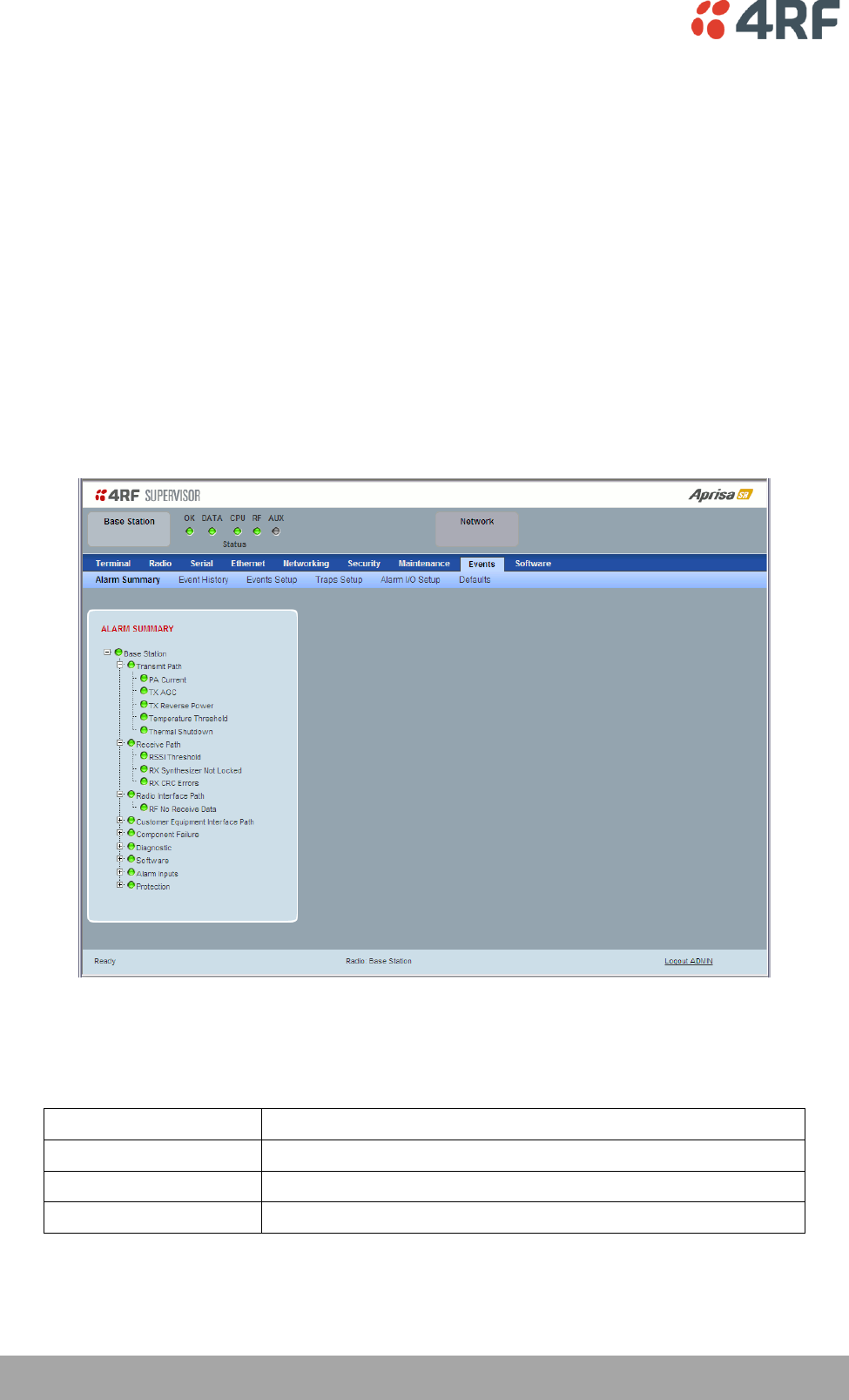
ALARM SUMMARY
The Alarm Summary is a display tree that displays the current states of all radio alarms. The alarm states
refresh automatically every 12 seconds.
LED Colour
Severity
Green
No alarm
Orange
Warning alarm
Red
Critical, major or minor alarm
Managing the Radio | 145
Aprisa SR User Manual
Events > Event History
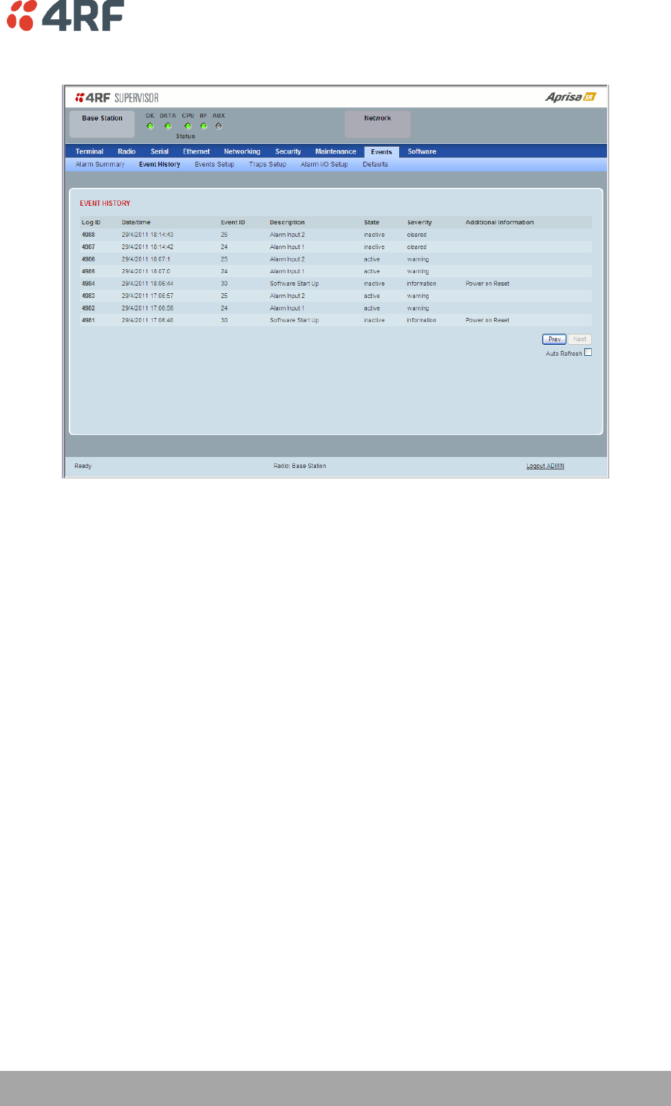
EVENT HISTORY
The last 1500 events are stored in the radio. The complete event list can be downloaded to a USB flash
drive (see ‘Write Alarm History to USB’ on page 135).
The Event History can display the last 50 events stored in the radio in blocks of 8 events.
The Next button will display the next page of 8 events and the Prev button will display the previous page
of 8 events. Using these buttons will disable Auto Refresh to prevent data refresh and page navigation
contention.
The last 50 events stored in the radio are also accessible via an SNMP command.
Auto Refresh
The Event History page selected will refresh automatically every 12 seconds if the Auto Refresh is ticked.
146 | Managing the Radio
Aprisa SR User Manual
Events > Events Setup
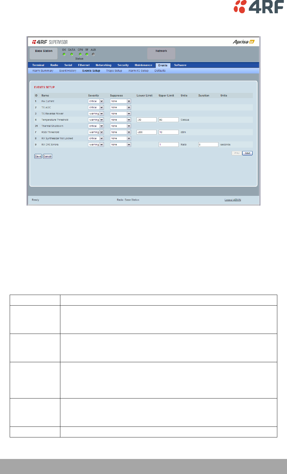
EVENTS SETUP
Alarm event parameters can be configured for all alarm events (see ‘Alarm Events’ on page 228).
All active alarms for configured alarm events will be displayed on the Parameters page (see ‘Terminal >
Parameters’ on page 87). This Switch and Block parameters are only visible / applicable when the radio is
part of a Protected Station.
Severity
The Severity parameter sets the alarm severity.
Severity
Function
Critical
The Critical severity level indicates that a service affecting condition has occurred and
an immediate corrective action is required. Such a severity can be reported, for
example, when a managed object becomes totally out of service and its capability must
be restored.
Major
The Major severity level indicates that a service affecting condition has developed and
an urgent corrective action is required. Such a severity can be reported, for example,
when there is a severe degradation in the capability of the managed object and its full
capability must be restored.
Minor
The Minor severity level indicates the existence of a non-service affecting fault
condition and that corrective action should be taken in order to prevent a more serious
(for example, service affecting) fault.
Such a severity can be reported, for example, when the detected alarm condition is not
currently degrading the capacity of the managed object.
Warning
The Warning severity level indicates the detection of a potential or impending service
affecting fault, before any significant effects have been felt. Action should be taken to
further diagnose (if necessary) and correct the problem in order to prevent it from
becoming a more serious service affecting fault.
Information
No problem indicated – purely information

Managing the Radio | 147
Aprisa SR User Manual
Suppress
This parameter determines if the action taken by an alarm.
Option
Function
None
Alarm triggers an event trap and is logged in the radio
Traps
Alarm is logged in the radio but does not trigger an event trap
Traps and Log
Alarm neither triggers an event trap nor is logged in the radio
Lower Limit / Upper Limit
Threshold alarm events have lower and upper limit settings. The alarm is activated if the current reading
is outside the limits.
Example: 9 RX CRC Errors
The Upper Limit is set to 0.7 and the Duration is set to 5 seconds.
If in any 5 second period, the total number of errored packets divided by the total number of received
packets exceeds 0.7, the alarm will activate.
Units (1)
The Units parameter shows the unit for the Lower Limit and Upper Limit parameters.
Duration
This parameter determines the period to wait before an alarm is raised if no data is received.
Units (2)
This parameter shows the unit for the Duration parameters.
Switch
This parameter determines if the alarm when active causes a switch over of the Protection Switch.
This parameter is only applicable when the radio is part of a Protected Station.
Block
This parameter determines if the alarm is prevented from causing a switch over of the Protection Switch.
This parameter is only applicable when the radio is part of a Protected Station.
The Next button will display the next page of 8 alarm events and the Prev button will display the previous
page of 8 alarm events.
148 | Managing the Radio
Aprisa SR User Manual
Events > Traps Setup
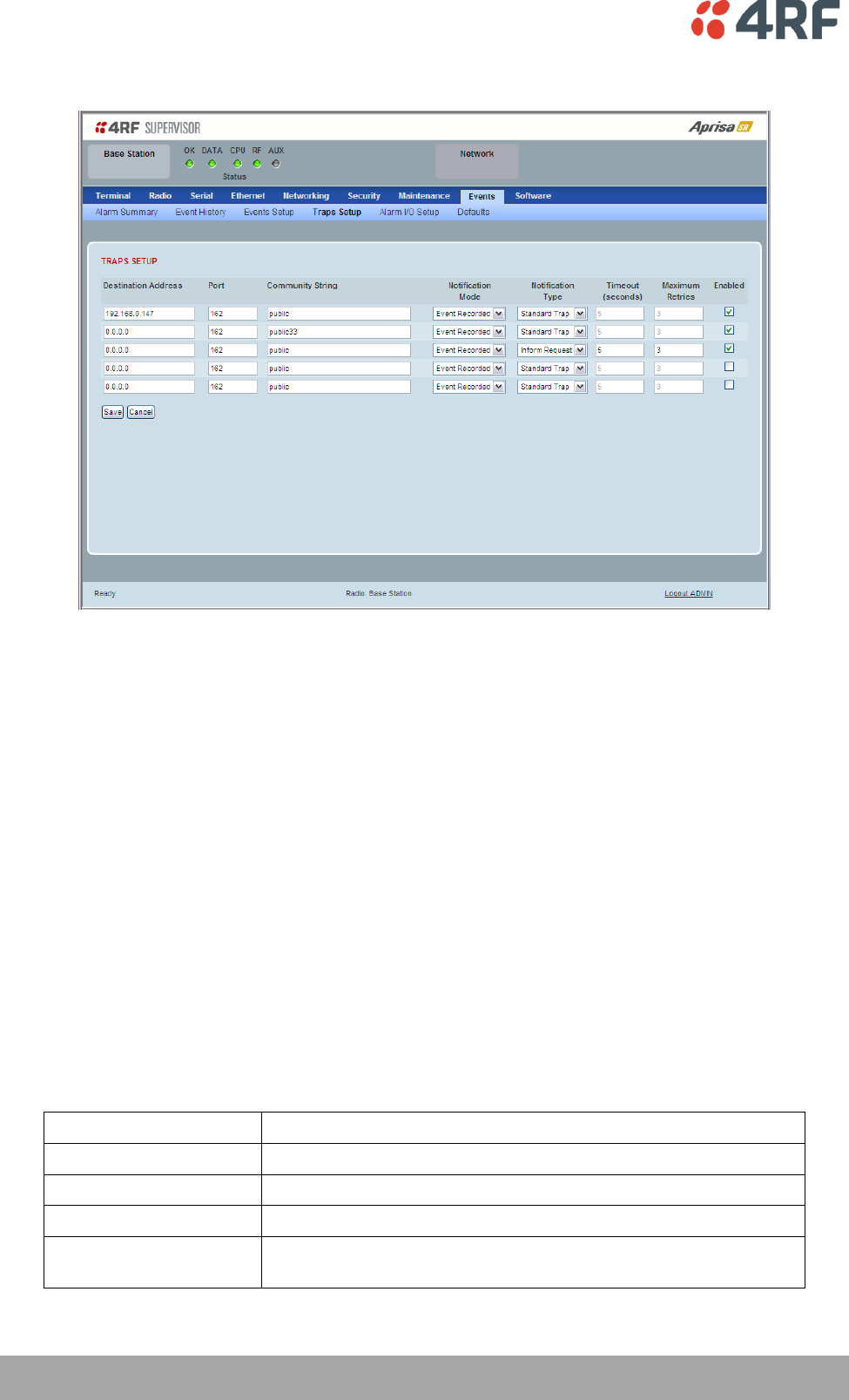
TRAPS SETUP
All events can generate SNMP traps. The types of traps that are supported are defined in the ‘Notification
Mode’.
Destination Address
This parameter sets the IP address of the server running the SNMP manager.
Port
This parameter sets the port number the server running the SNMP manager.
Community String
This parameter sets the community string which is sent with the IP address for security. The default
community string is ‘public’.
Notification Mode
This parameter sets when an event related trap is sent:
Option
Function
None
No event related traps are sent.
Event Recorded
When an event is recorded in the event history log, a trap is sent.
Event Updated
When an event is updated in the event history log, a trap is sent.
All Events
When an event is recorded or updated in the event history log, a
trap is sent.

Managing the Radio | 149
Aprisa SR User Manual
Notification Type
This parameter sets the type of event notification:
Option
Function
Standard Trap
Provides a standard SNMP trap event
Inform Request
Provides a SNMP v2 Inform Request trap event including trap retry
and acknowledgement
Notification Type set to Inform Request:
Timeout (second)
This parameter sets the time interval to wait for an acknowledgement before sending another retry.
Maximum Retries
This parameter sets the maximum number of retries to send the event without acknowledgement before it
gives up.
Enabled
This parameter determines if the entry is used.
150 | Managing the Radio
Aprisa SR User Manual
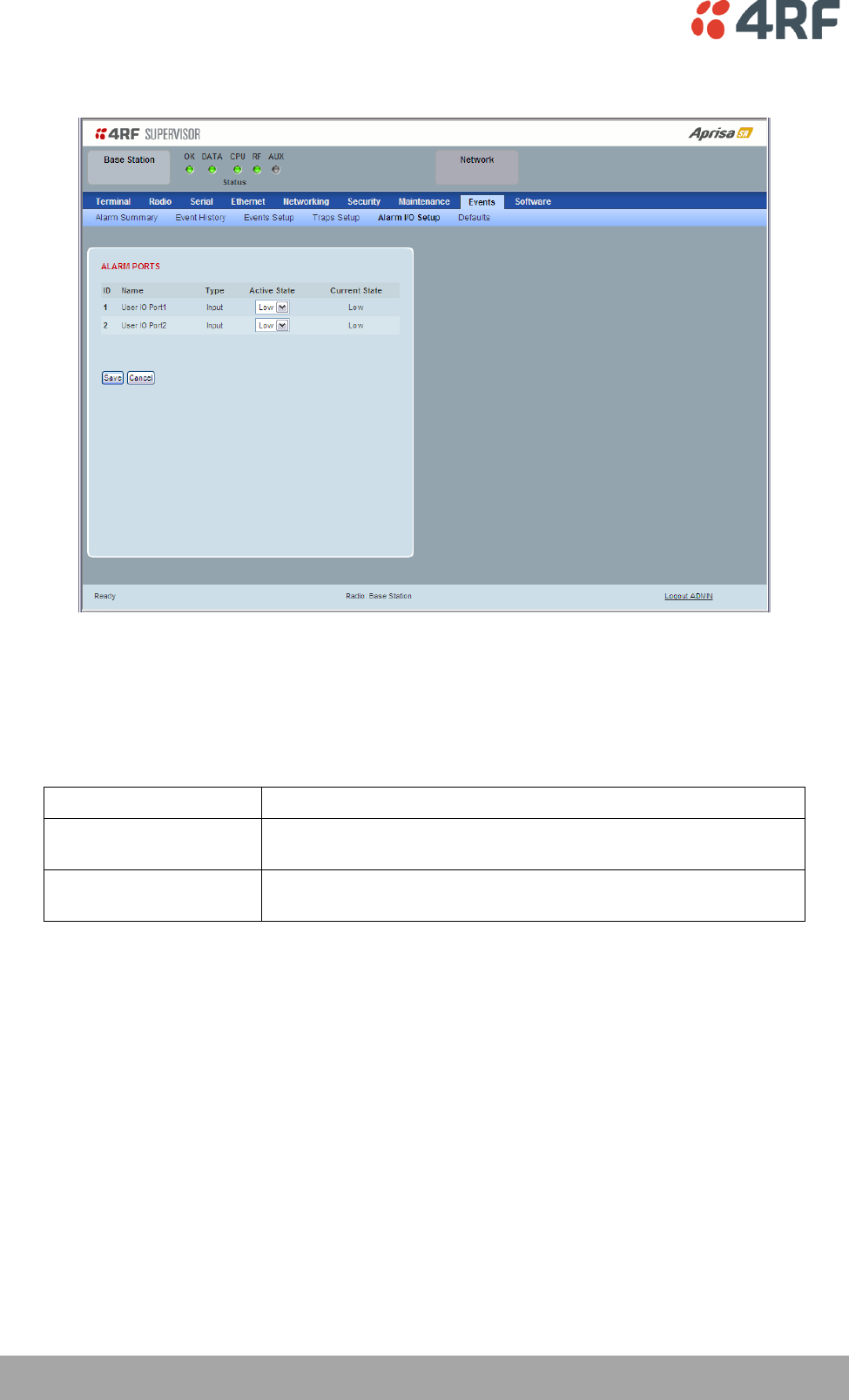
Events > Alarm I/O Setup
ALARM PORTS
This page provides control of the two hardware alarm inputs provided on the power and alarm connector.
These alarms are only available when the station is non protected (see ‘Hardware Alarms Connections’ on
page 227).
Option
Function
Low
The alarm is active low i.e. a logic 0 on the port will cause an
alarm state
High
The alarm is active high i.e. a logic 1 on the port will cause an
alarm state
Managing the Radio | 151
Aprisa SR User Manual
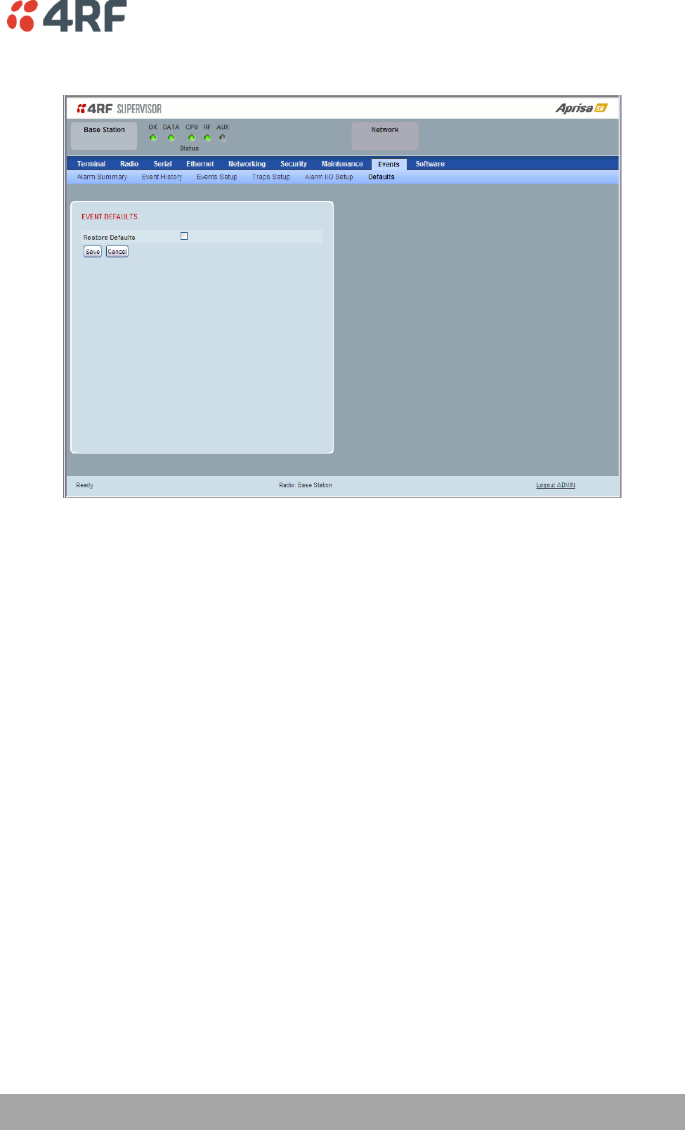
Events > Defaults
EVENT DEFAULTS
Restore Defaults
This parameter when activated restores all previously configured event parameters using ‘Events > Events
Setup’ to the factory default settings.

152 | Managing the Radio
Aprisa SR User Manual
Software
The Software menu contains the setup and management of the system software including network
software distribution and activation.
Single Radio Software Upgrade
The radio software can be upgraded on a single radio single Aprisa SR radio (see ‘Single Radio Software
Upgrade’ on page 223). This process would only be used if the radio was a replacement or a new station in
an existing network.
Network Software Upgrade
The radio software can be upgraded on an entire Aprisa SR radio network remotely over the radio link (see
‘Network Software Upgrade’ on page 222). This process involves following steps:
1. Transfer the new software to base station with ‘Software > File Transfer’
2. Distribute the new software to all remote stations with ‘Software > Remote Distribution’
3. Activate of the new software on remote stations with ‘Software > Remote Activation’.
4. Finally, activate the new software on the base station radio with ‘Software > Manager’. Note:
activating the software will reboot the radio.
Managing the Radio | 153
Aprisa SR User Manual
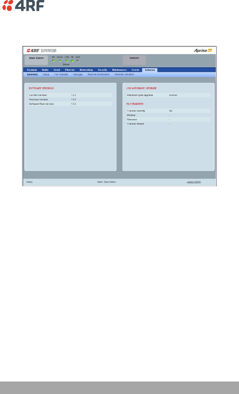
Software > Summary
This page provides a summary of the software versions installed on the radio, the setup options and the
status of the File Transfer.

154 | Managing the Radio
Aprisa SR User Manual
SOFTWARE VERSIONS
Current Version
This parameter displays the software version running on the radio.
Previous Version
This parameter displays the software version that was running on the radio prior to the current software
being activated.
Software Pack Version
On the base station, this parameter displays the software version available for distribution to all radios in
the network.
On the all stations, this parameter displays the software version ready for activation.
USB AUTOMATIC UPGRADE
USB Boot Upgrade
This parameter shows the type of USB Boot upgrade defined in ‘Software Setup > USB Boot Upgrade’ on
page 155.
FILE TRANSFER
Transfer Activity
This parameter shows the status of the transfer, ‘Idle’, ‘In Progress’ or ‘Completed’.
Method
This parameter shows the file transfer method.
File
This parameter shows the software file source.
Transfer Result
This parameter shows the progress of the transfer.
Managing the Radio | 155
Aprisa SR User Manual
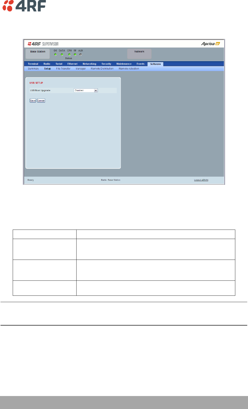
Software > Setup
This page provides the setup of the USB flash drive containing a Software Pack.
USB SETUP
USB Boot Upgrade
This parameter determines the action taken when the radio power cycles and finds a USB flash drive in the
Host port. The default setting is ‘Load and Activate’.
Option
Function
Load and Activate
New software will be uploaded from a USB flash drive in to the
Aprisa SR when the radio is power cycled and activated
automatically.
Load Only
New software will be uploaded from a USB flash drive in to the
Aprisa SR when the radio is power cycled. The software will need
to be manually activated (see ‘Software > Manager’ on page 159).
Disabled
Software will not be uploaded from a USB flash drive into the
Aprisa SR when the radio is power cycled.
Note: This parameter must be set to ‘Disabled’ if the ‘File Transfer and Activate’ method of upgrade is
used. This ‘Disabled’ setting prevents the radio from attempting another software upload when the radio
boots (which it does automatically after activation).
156 | Managing the Radio
Aprisa SR User Manual
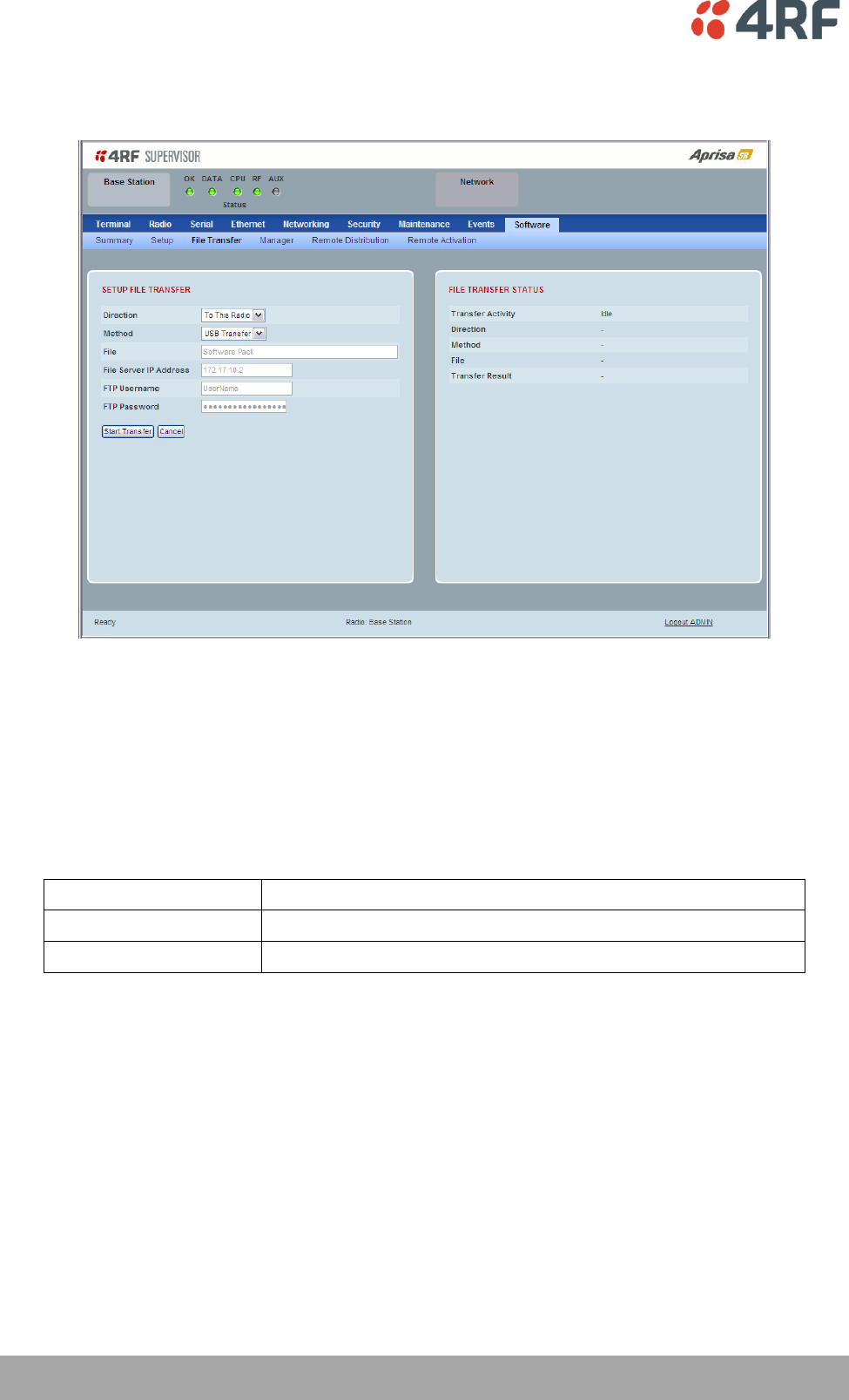
Software > File Transfer
This page provides the mechanism to transfer new software from a file source into the radio.
SETUP FILE TRANSFER
Direction
This parameter sets the direction of file transfer. In this software version, the only choice is ‘To the
Radio’.
Method
This parameter sets the method of file transfer.
Option
Function
USB Transfer
Transfers the software from the USB flash drive to the radio.
FTP
Transfers the software from an FTP server to the radio.
File
This parameter shows the software file source.
FTP Username
This parameter sets the Username to access the FTP server.
FTP Password
This parameter sets the Password to access the FTP server.
Managing the Radio | 157
Aprisa SR User Manual
FILE TRANSFER STATUS
Transfer Activity
This parameter shows the status of the transfer, ‘Idle’, ‘In Progress’ or ‘Completed’.
Direction
This parameter shows the direction of file transfer. In this software version, the only choice is ‘To The
Radio’.
Method
This parameter shows the file transfer method.
File
This parameter shows the software file source.
Transfer Result
This parameter shows the progress of the transfer:
Transfer Result
Function
Starting Transfer
The transfer has started but no data has transferred.
In Progress (x %)
The transfer has started and has transferred x % of the data.
Successful
The transfer has finished successfully.
File Error
The transfer has failed.
Possible causes of failure are:
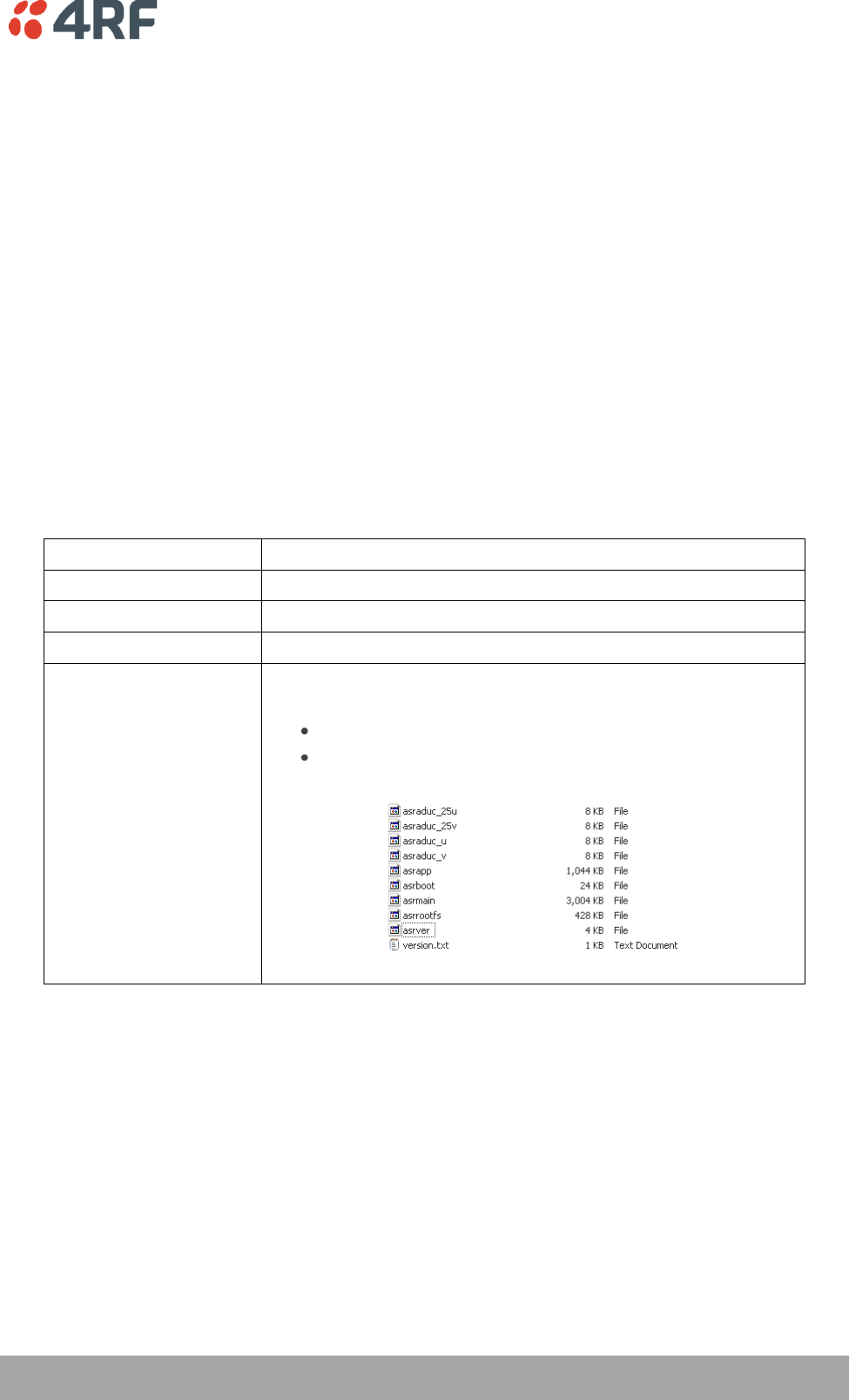
Is the source file available e.g. USB flash drive plugged in
Does the file source contain the Aprisa SR software release
files;

158 | Managing the Radio
Aprisa SR User Manual
To transfer software into the Aprisa SR radio:
USB Transfer Method
1. Unzip the software release files in to the root directory of a USB flash drive.
2. Insert the USB flash drive into the Host Port .
3. Click on ‘Start Transfer’.
4. When the transfer is completed, remove the USB flash drive from the Host Port. If the SuperVisor ‘USB
Boot Upgrade’ setting is set to ‘Disabled’ (see ‘USB Boot Upgrade’ on page 155), the USB flash drive
doesn’t need to be removed as the radio won’t try to load from it.
Go to Supervisor > Software > Manager and activate the Software Pack (see ‘Software > Manager’ on page
159). The radio will reboot automatically.
If the file transfer fails, check the Event History page (see ‘Events > Event History’ on page 145) for more
details of the transfer.
FTP Method
1. Unzip the software release files in to a temporary directory.
2. Open the FTP server and point it to the temporary directory.
3. Enter the FTP server IP address, Username and password into SuperVisor.
4. Click on ‘Start Transfer’.
Go to Supervisor > Software > Manager and activate the Software Pack (see ‘Software > Manager’ on page
159). The radio will reboot automatically.
If the file transfer fails, check the Event History page (see ‘Events > Event History’ on page 145) for more
details of the transfer.
Managing the Radio | 159
Aprisa SR User Manual
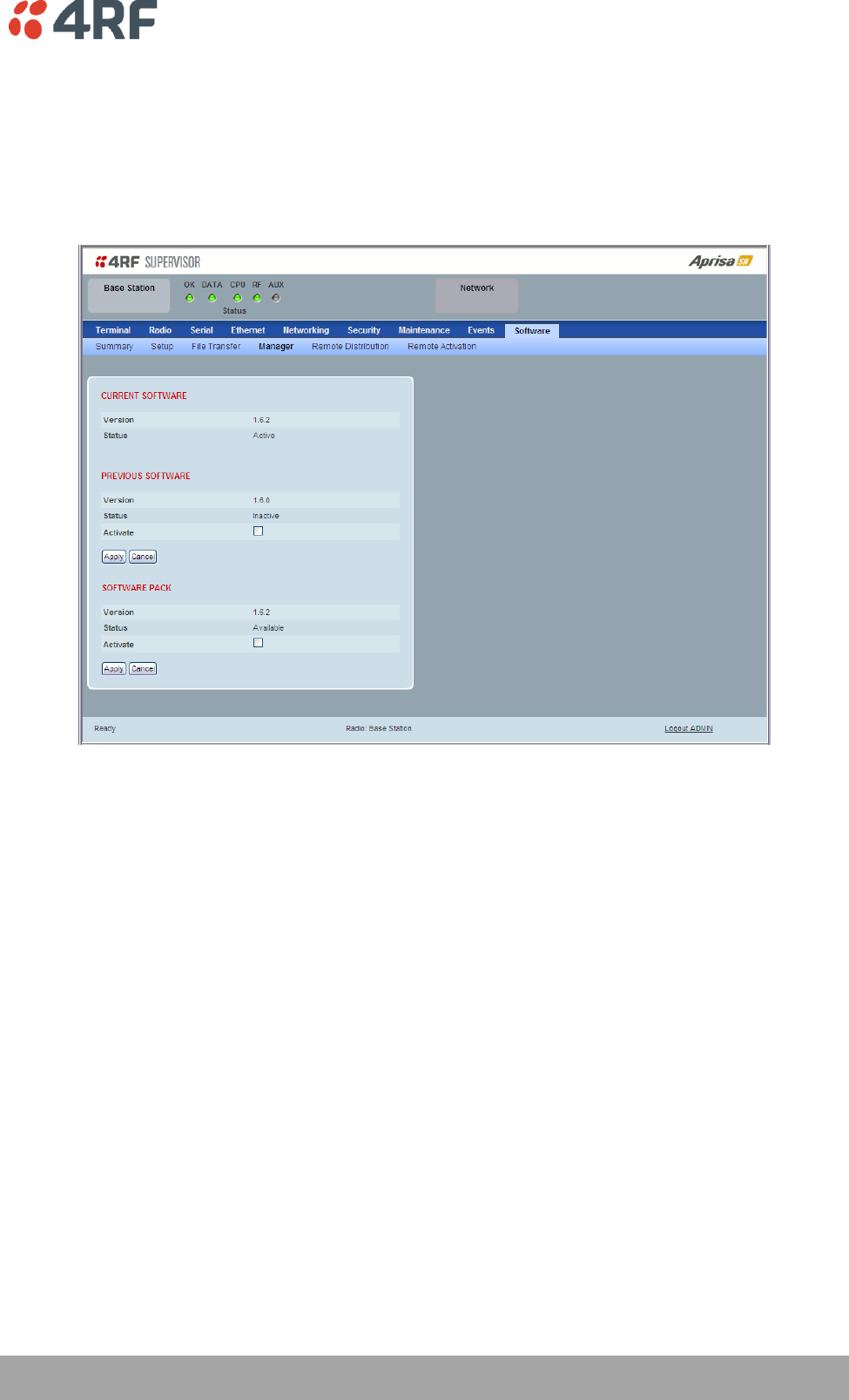
Software > Manager
This page summarises and manages the software versions available in the radio.
The manager is predominantly used to activate new software on single radios. Network activation is
performed with ‘Software > Remote Activation’.
Both the previous software (if available) and Software Pack versions can be activated on the radio from
this page.
CURRENT SOFTWARE
Version
This parameter displays the software version running on the radio.
Status
This parameter displays the status of the software version running on the radio (always active).
160 | Managing the Radio
Aprisa SR User Manual
PREVIOUS SOFTWARE
Version
This parameter displays the software version that was running on the radio prior to the current software
being activated.
Status
This parameter displays the status of the software version that was running on the radio prior to the
current software being activated.
Option
Function
Active
The software is operating the radio.
Inactive
The software is not operating the radio but could be re-activated if
required.
Activate
This parameter activates the previous software version (restores to previous version).
The Aprisa SR will automatically reboot after activation.
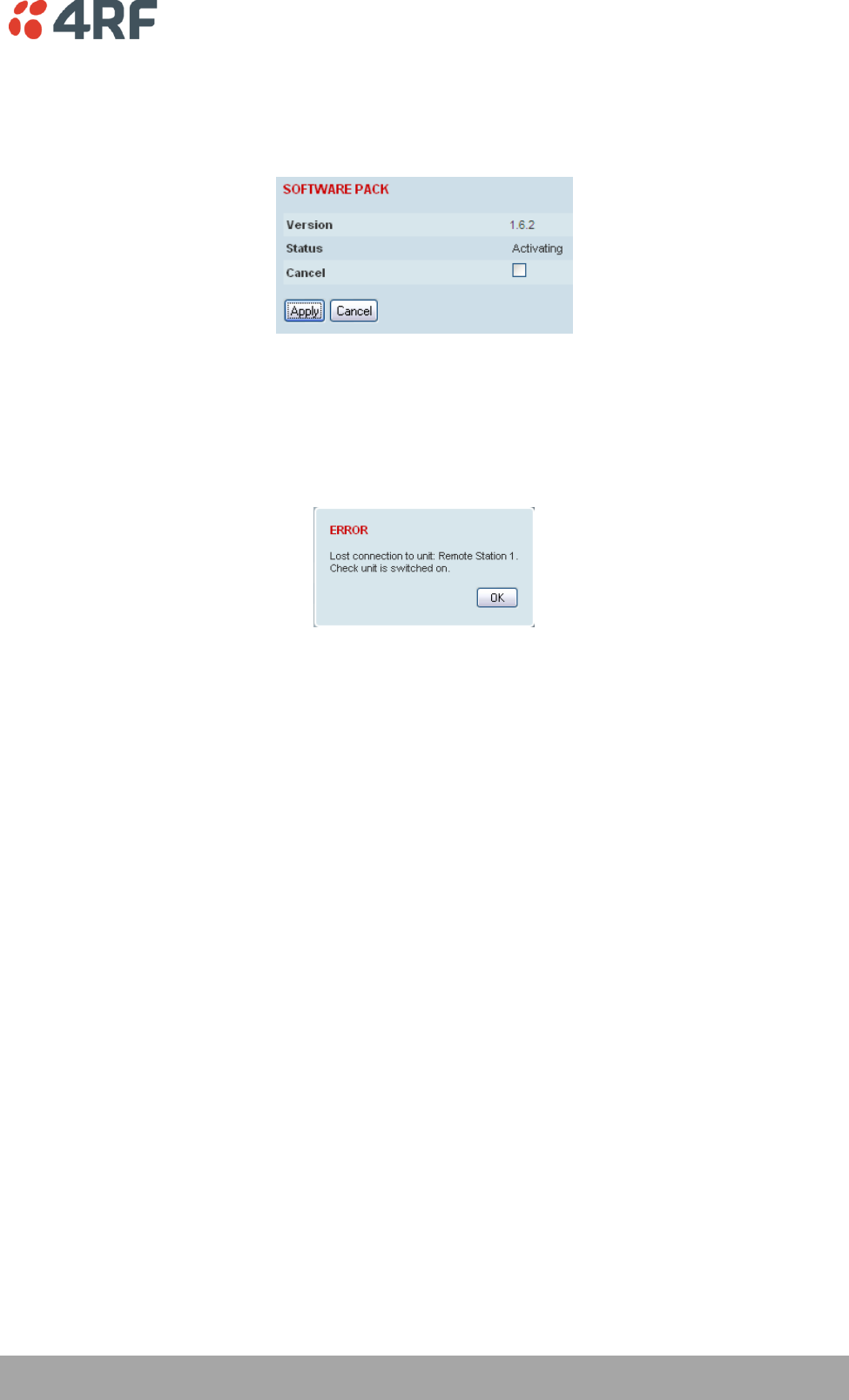
SOFTWARE PACK
Version
This parameter displays the software pack version available for distribution on base station and activate
on all stations.
Status
This parameter displays the status of the software pack version.
Option
Function
Available
On the base station, the software pack is available for distribution.
On all stations, the software pack is available for activation.
Activating
The software pack is activating in the radio.
Unavailable
There is no software pack loaded into the radio.
Activate
This parameter activates the software pack.
The Aprisa SR will automatically reboot after activation.
Managing the Radio | 161
Aprisa SR User Manual
To activate a software version:
1. Tick the software version required to be activated (previous software or software pack).
2. Click ‘Apply’.
The page will display a Status of ‘Activating’.
Once started, activation cannot be cancelled.
When the activation is completed, the radio will reboot. This will cause the current SuperVisor session to
expire.
3. Login to SuperVisor to check the result.
162 | Managing the Radio
Aprisa SR User Manual
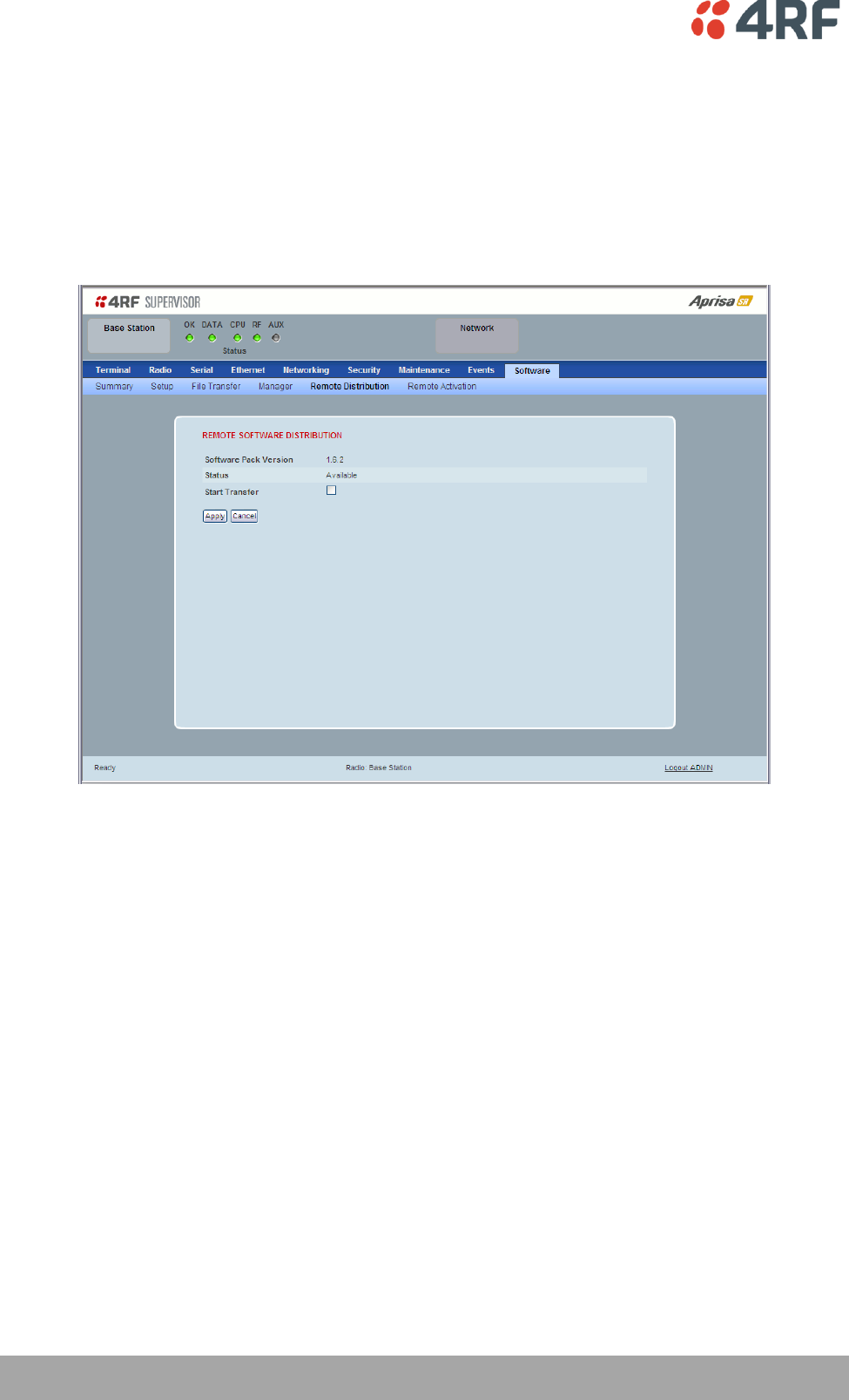
Software > Remote Distribution
This page provides the mechanism to distribute software to all remote stations into the Aprisa SR network
(network) and then activate it.
The Software Pack that was loaded into the base station with the file transfer process (see ‘Software >
File Transfer’ on page 156) can be distributed via the radio link to all remote stations.
This page is used to manage the distribution of that software pack to all remote radios on the network.
This page is only available when the radio is configured as a Base Station.
REMOTE SOFTWARE DISTRIBUTION
Software Pack Version
This parameter displays the software pack version available for distribution on base station and activate
on all stations.
Status
This parameter displays the status of the software pack version.
If a Software Pack is not available, the status will display ‘Unavailable’ and the software distribution
mechanism will not work.
Managing the Radio | 163
Aprisa SR User Manual
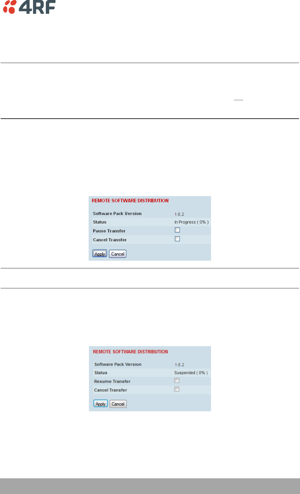
Start Transfer
This parameter when activated distributes (broadcasts) the new Software Pack to all remote stations in
the network.
Note: The distribution of software to remote stations does not stop customer traffic from being
transferred. However, due to the volume of traffic, the software distribution process may affect customer
traffic.
Software distribution traffic is classified as ‘management traffic’ but does not use the Ethernet
management priority setting. Software distribution traffic priority has a fixed priority setting of ‘very
low’.
To distribute software to remote stations:
This process assumes that a Software Pack has been loaded into the base station with the file transfer
process (see ‘Software > File Transfer’ on page 156).
1. To ensure that the Network Table is up to date, it is recommended running the node discover function
(see ‘Discover Nodes’ on page 142).
2. Click on ‘Start Transfer’.
Note: This process could take anywhere between 40 minutes and several hours depending on channel size,
Ethernet Management Priority setting and the amount of customer traffic on the network.
3. When the distribution is completed, activate the software with the Remote Software Activation.
Pause Transfer
This parameter when activated, pauses the distribution process and shows the distribution status. The
distribution process will continue from where it was paused with Resume Transfer.
Cancel Transfer
This parameter when activated, cancels the distribution process immediately.
During the distribution process, it is possible to navigate away from this page and come back to it to check
progress. The SuperVisor session will not timeout.
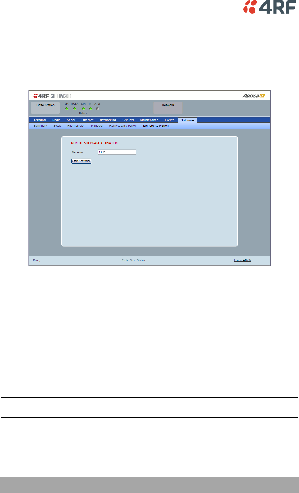
164 | Managing the Radio
Aprisa SR User Manual
Software > Remote Activation
This page provides the mechanism to activate software on all remote stations.
The Software Pack was loaded into the base station with the file transfer process (see ‘Software > File
Transfer’ on page 156) and was distributed via the radio link to all remote stations.
This page is used to manage the activation of that software pack on all remote radios on the network.
This page is only available when the radio is configured as a Base Station.
REMOTE SOFTWARE ACTIVATION
When the software pack version has been distributed to all the remote stations, the software is then
activated in all the remote stations with this command. If successful, then activate the software pack in
the base station to complete the network upgrade.
Version
This parameter displays the software version for activation. The default version is the software pack
version but any valid software version can be entered in the format ‘n.n.n’.
To activate software in remote stations:
This process assumes that a Software Pack has been loaded into the base station with the file transfer
process (see ‘Software > File Transfer’ on page 156) and distributed to all remote radios in the network.
Note: Do not navigate SuperVisor away from this page during the activation process (SuperVisor can lose
PC focus).
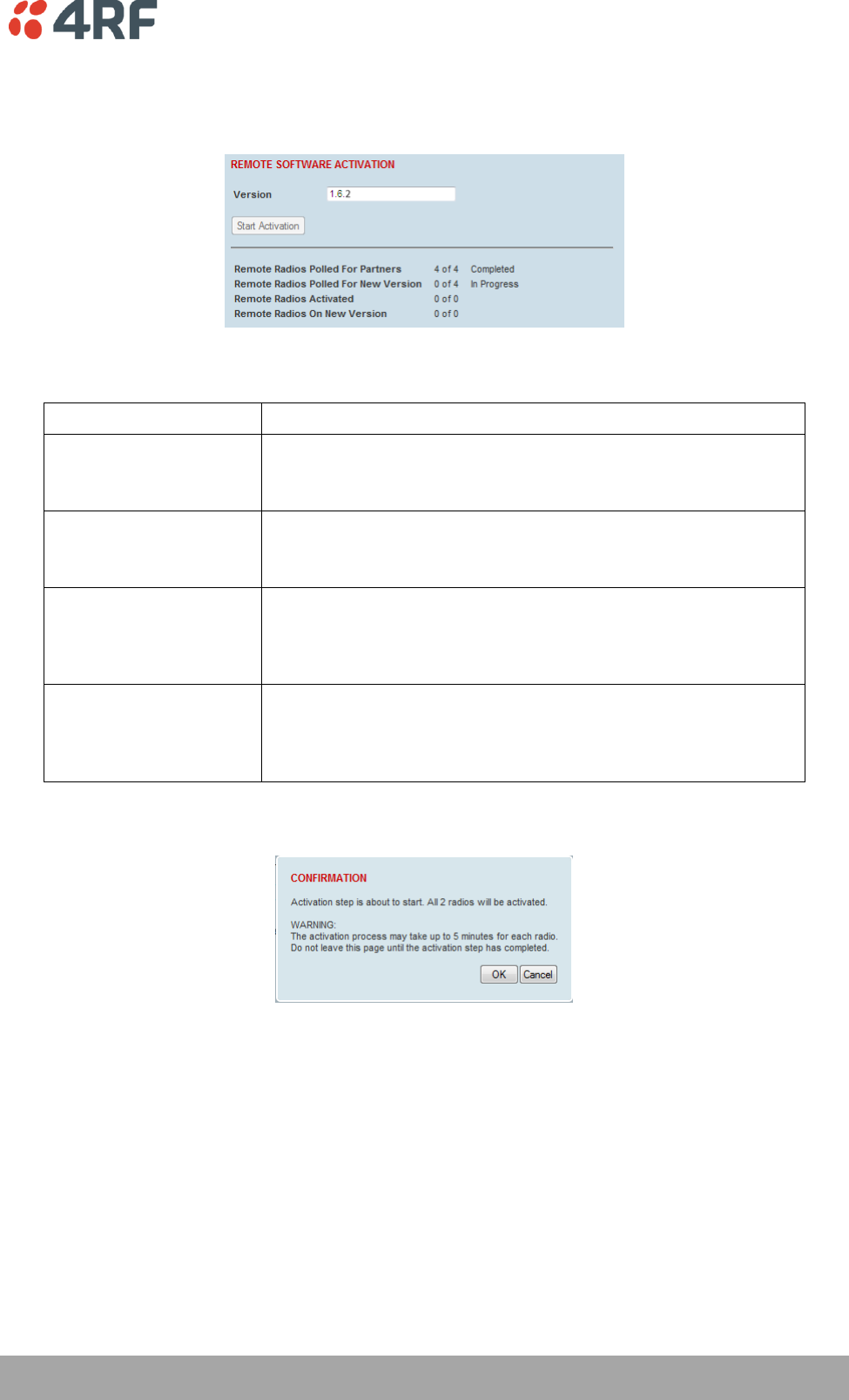
Managing the Radio | 165
Aprisa SR User Manual
1. Enter the Software Pack version (if different from displayed version).
2. Click on ‘Start Activation’.
The remote stations will be polled to determine which radios require activation:
Result
Function (X of Y)
Remote Radios Polled for
Partners
X is the number of radios polled to determine the number of
protected stations in the network.
Y is the number of remote radios registered with the base station.
Remote Radios Polled for
New Version
X is the number of radios polled to determine the number of radios
that contain the new software version.
Y is the number of remote radios registered with the base station.
Remote Radios Activated
X is the number of radios that contain the new software version
and have been activated.
Y is the number of radios that contain the new software version
and can be activated.
Remote Radios On New
Version
X is the number of radios that has been successfully activated and
now running the new version of software.
Y is the number of radios that the activation command was
executed on.
When the activation is ready to start:
3. Click on ‘OK’ to start the activation process or Cancel to quit.
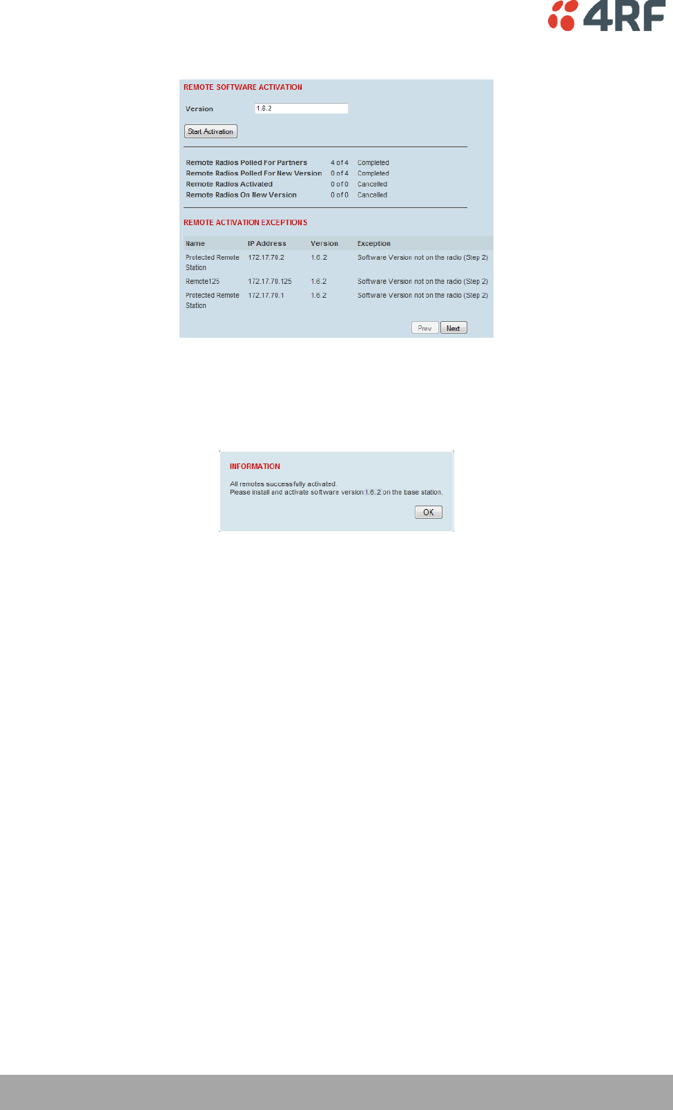
166 | Managing the Radio
Aprisa SR User Manual
The page will display the progress of the activation.
The example shows that during the activation process there were exceptions that may need to be
investigated.
When all the remote radios have been activated, the base station radio must now be activated with (see
‘Software > Manager’ on page 159).
4. Click on ‘OK’ to start the activation on the base station.
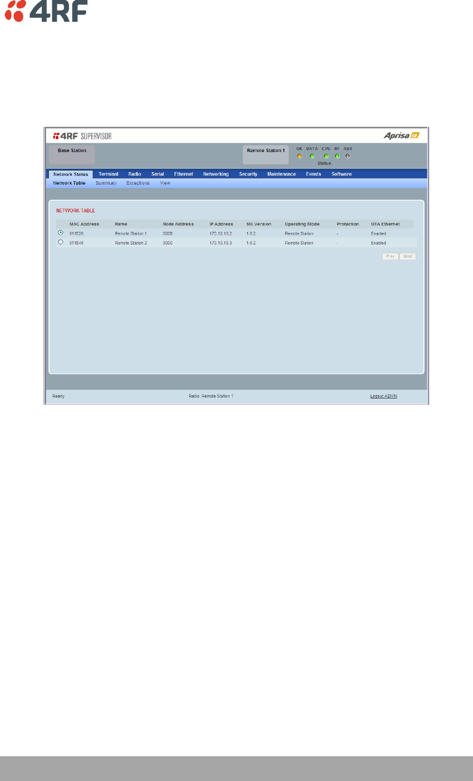
Managing the Radio | 167
Aprisa SR User Manual
Network Status
Network Status > Network Table
This page displays a list of all the registered remote stations for the base station and provides
management access to each of the remote stations.
NETWORK TABLE
This Network Table is only available when the local radio is the base station i.e. SuperVisor is logged into
the base station.
To manage a remote / repeater station with SuperVisor:
Click on the radio button of the required station. The remaining menu items then apply to the selected
remote station.
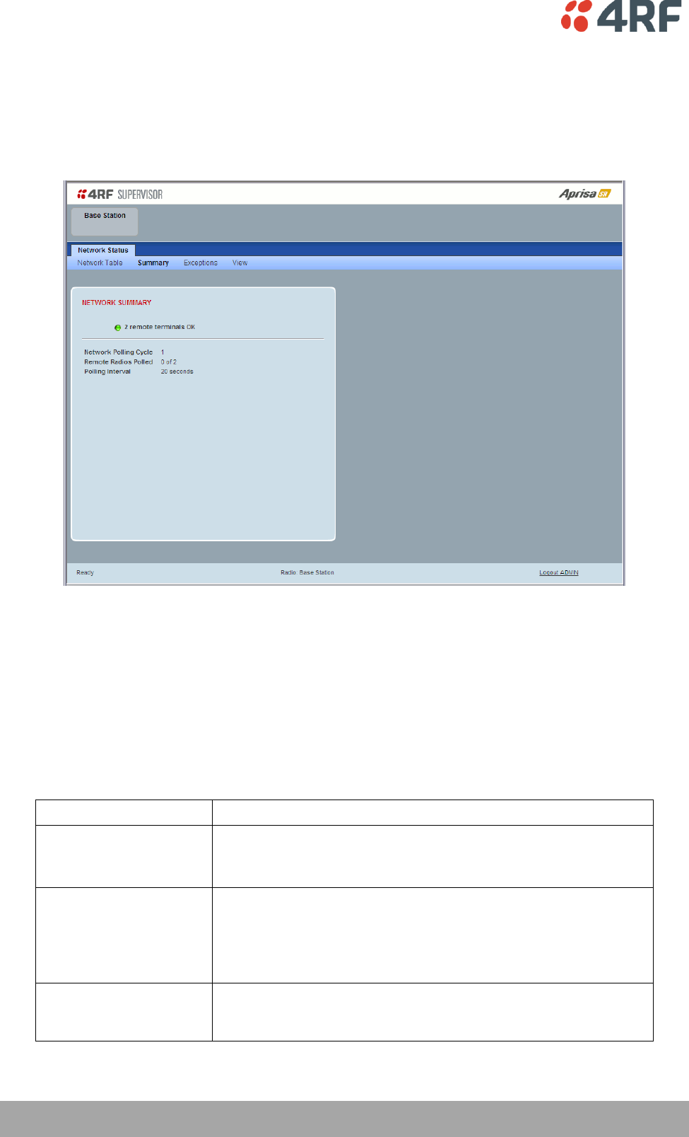
168 | Managing the Radio
Aprisa SR User Manual
Network Status > Summary
Network View is an overview of the health of the network providing the ability to investigate issues
directly within SuperVisor.
This page provides an overall summary view of the alarm status of all registered remote stations for the
base station. When open, it provides a continuous monitor of the network.
NETWORK SUMMARY
A network poll will start when any of the Network Status pages are opened (Summary, Exceptions or
View). The network poll will only continue to poll the remote stations if one of the Network Status pages
is open (SuperVisor can lose PC focus). The network poll continues from where it was stopped last time it
was polling.
The initial result assumes that all remote stations are operating correctly.
Network Summary Example:
Result
Function
Network Polling Cycle
The number of poll cycles since first opening a Network Status >
Summary, Exceptions or View page.
The page example shows 6 polling cycles.
Remote Radios Polled
This shows the number of radios polled for the current polling
cycle out of the number remote radios registered with the base
station.
The page example shows 1 radio polled for the current polling
cycle out of 3 remote radios registered.
Polling Interval
The time interval between the completion of one radio poll and
the start of the next radio poll. To set the polling interval, see
‘Maintenance > General’ on page 134.

Managing the Radio | 169
Aprisa SR User Manual
If a remote radio does not respond to a poll request within 10 seconds, the previous readings from that
radio will be presented. Connectivity to a remote radio will be show as ‘lost’ if the remote radio has not
responded to 3 consecutive poll requests.
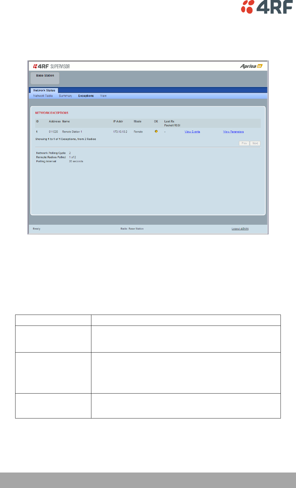
170 | Managing the Radio
Aprisa SR User Manual
Network Status > Exceptions
This page provides a list of all registered remote radios that are in an alarmed state or have stopped
responding to the SuperVisor polling. When open, it provides a continuous monitor of the network.
NETWORK EXCEPTIONS
A network poll will start when any of the Network Status pages are opened (Summary, Exceptions or
View). The network poll will only continue to poll the remote stations if one of the Network Status pages
is open (SuperVisor can lose PC focus). The network poll continues from where it was stopped last time it
was polling.
Network Exceptions Example:
Result
Function
Network Polling Cycle
The number of poll cycles since first opening a Network Status >
Summary, Exceptions or View page.
The page example shows 4 polling cycles.
Remote Radios Polled
This shows the number of radios polled for the current polling
cycle out of the number remote radios registered with the base
station.
The page example shows 3 radios polled for the current polling
cycle out of 4 remote radios registered.
Polling Interval
The time interval between the completion of one radio poll and
the start of the next radio poll. To set the polling interval, see
‘Maintenance > General’ on page 134.

Managing the Radio | 171
Aprisa SR User Manual
If a remote radio does not respond to a poll request within 10 seconds, the previous readings from that
radio will be presented. Connectivity to a remote radio will be show as ‘lost’ if the remote radio has not
responded to 3 consecutive poll requests.
If a remote radio on the list is detected to be responding to a poll request and no longer be in an alarmed
state, the entry for this remote radio will be removed from the list.
View Events
Clicking on View Events navigates to the Events page (see ‘Events’ on page 144) for the specific remote
radio where the radio events will be displayed.
View Parameters
Clicking on View Parameters navigates to Terminal > Parameters page (see ‘Terminal > Parameters’ on
page 87) for the specific remote radio where the radio parameters will be displayed.
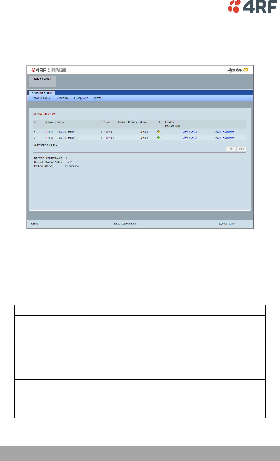
172 | Managing the Radio
Aprisa SR User Manual
Network Status > View
This page provides a complete list of all registered remote radios. It is similar to the Exceptions page but
it shows all radios, not limited to the radios with alarms. When open, it provides a continuous monitor of
the network.
NETWORK VIEW
A network poll will start when any of the Network Status pages are opened (Summary, Exceptions or
View). The network poll will only continue to poll the remote stations if one of the Network Status pages
is open (SuperVisor can lose PC focus). The network poll continues from where it was stopped last time it
was polling.
Network View Example:
Result
Function
Network Polling Cycle
The number of poll cycles since first opening a Network Status >
Summary, Exceptions or View page.
The page example shows 2 polling cycles.
Remote Radios Polled
This shows the number of radios polled for the current polling
cycle out of the number remote radios registered with the base
station.
The page example shows 1 radio polled for the current polling
cycle out of 3 remote radios registered.
Polling Interval
The time interval between the completion of one radio poll and
the start of the next radio poll. To set the polling interval, see
‘Maintenance > General’ on page 134.
Note: as this polling feature utilizes air time, the polling interval
should be selected to suit the network traffic.

Managing the Radio | 173
Aprisa SR User Manual
If a remote radio does not respond to a poll request within 10 seconds, the previous readings from that
radio will be presented. Connectivity to a remote radio will be show as ‘lost’ if the remote radio has not
responded to 3 consecutive poll requests.
View Events
Clicking on View Events navigates to the Events page (see ‘Events’ on page 144) for the specific remote
radio where the radio events will be displayed.
View Parameters
Clicking on View Parameters navigates to Terminal > Parameters page (see ‘Terminal > Parameters’ on
page 87) for the specific remote radio where the radio parameters will be displayed.

174 | Managing the Radio
Aprisa SR User Manual
Protected Station
The majority of SuperVisor screens are the same for the standard radio and the protected station. The
following screens are specific to the protected station.
Parameter Errors
On protected station screens, parameter values displayed in red indicate discrepancies in common
parameter values between the primary and secondary radios (see ‘Protected Station: Terminal >
Summary’ on page 175 for an example of the red display). The value displayed is from the ‘addressed
radio’.
These value discrepancies can occur if the two protected station radios have been separately configured.
The discrepancies can be corrected by re-entering the values in one of the radios. The value will be
copied to the partner radio.
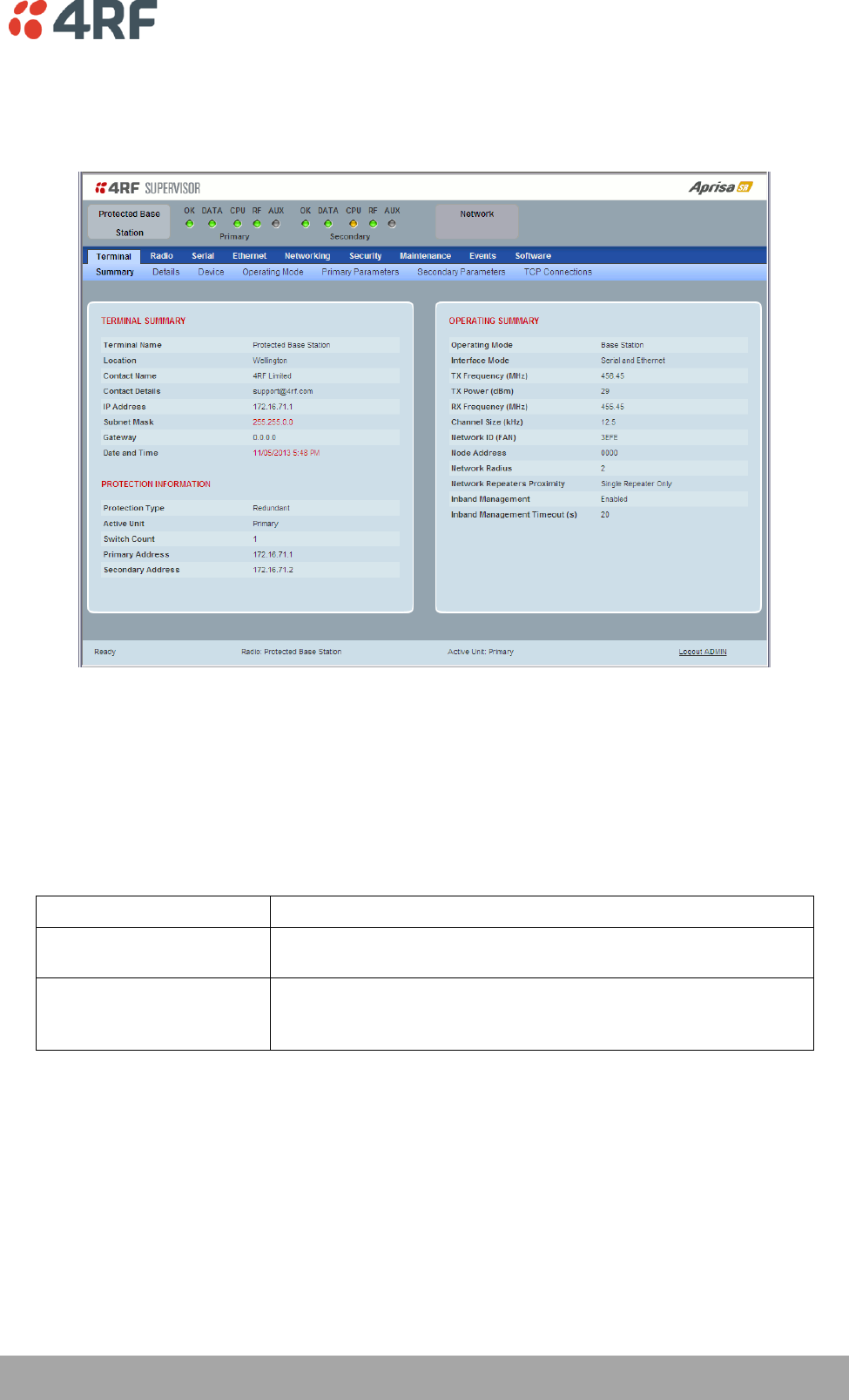
Managing the Radio | 175
Aprisa SR User Manual
Terminal
Protected Station: Terminal > Summary
TERMINAL SUMMARY
This page displays the current settings for the Terminal parameters.
PROTECTION INFORMATION
Protection Type
This parameter shows the type of protection:
Option
Function
Serial Data Driven Switching
Provides radio and RS-232 serial port user interface protection for
Aprisa SR radios.
Redundant
(Protected Station)
The RF ports and interface ports from two standard Aprisa SR
Radios are switched to the standby radio if there is a failure in the
active radio
Active Unit
This parameter shows the radio which is currently active (Primary or Secondary).

176 | Managing the Radio
Aprisa SR User Manual
Switch Count
This parameter shows the number of protection switch-overs since the last radio reboot (volatile).
Primary Address
This parameter shows the IP address of the primary radio (usually the left side radio A).
Secondary Address
This parameter shows the IP address of the secondary radio (usually the right side radio B).
OPERATING SUMMARY
See ‘Terminal > Summary’ on page 78 for parameter details.
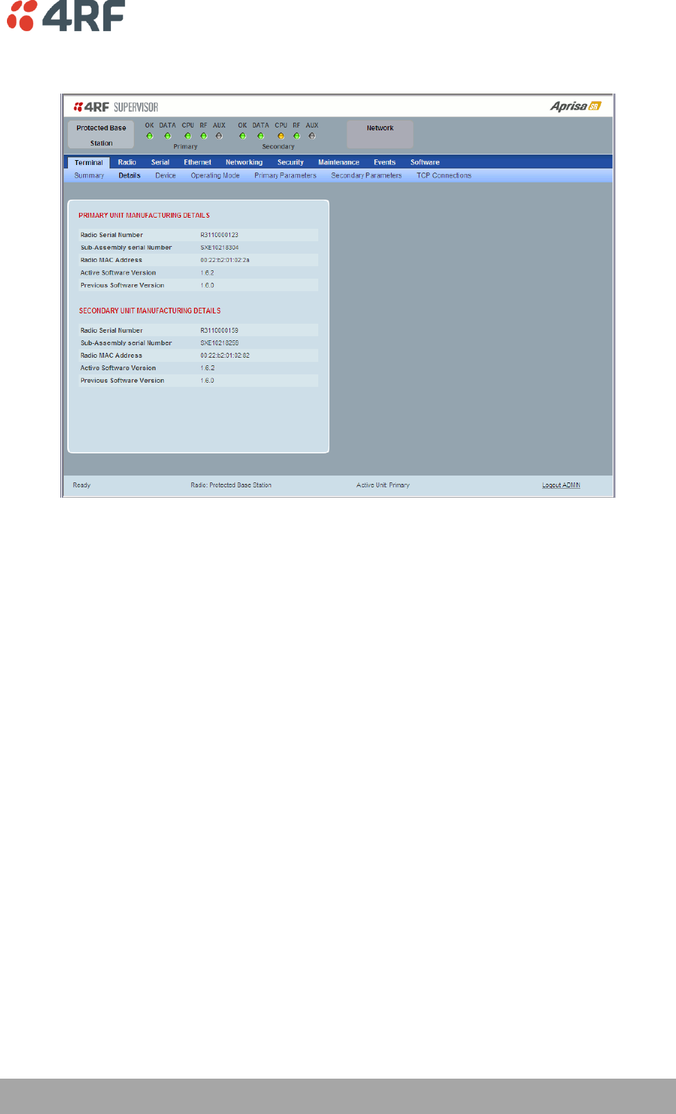
Managing the Radio | 177
Aprisa SR User Manual
Protected Station: Terminal > Details
PRIMARY UNIT / SECONDARY UNIT MANUFACTURING DETAILS
See ‘Terminal > Details’ on page 80 for parameter settings.
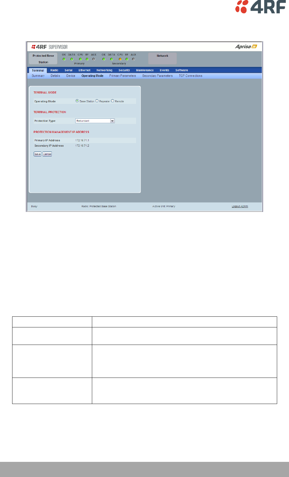
178 | Managing the Radio
Aprisa SR User Manual
Protected Station: Terminal > Operating Mode
TERMINAL MODE
Operating Mode
The Operating Mode can be set to base station, repeater station or remote station. The default setting is
remote station.
TERMINAL PROTECTION
Protection Type
The Protection Type defines if a radio is a stand-alone radio or part of an Aprisa SR Protected Station. The
default setting is None.
Option
Function
None
The SR radio is stand alone radio (not part of an Aprisa SR
Protected Station).
Redundant
(Protected Station)
The SR radio is part of an Aprisa SR Protected Station.
The RF ports and interface ports from two standard Aprisa SR
Radios are switched to the standby radio if there is a failure in the
active radio
Serial Data Driven Switching
The SR radio is part of an Aprisa SR Data Driven Protected Station.
Provides radio and RS-232 serial port user interface protection for
Aprisa SR radios.

Managing the Radio | 179
Aprisa SR User Manual
PROTECTION MANAGEMENT IP ADDRESS
Primary Address
This parameter shows the IP address of the primary radio (usually the left side radio A).
Secondary Address
This parameter shows the IP address of the secondary radio (usually the right side radio B).
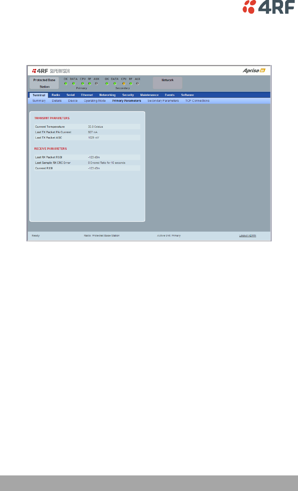
180 | Managing the Radio
Aprisa SR User Manual
Protected Station: Terminal > Primary Parameters
The Parameters page is a dynamic page that will display the parameters associated with the active
alarms, set on ‘Events > Events Setup’ on page 146. The screenshot below shows a small amount of
monitored alarms as an example.
TRANSMIT / RECEIVE PARAMETERS
This parameter displays the parameters of the Primary radio.
See ‘Terminal > Parameters’ on page 87 for parameter details.
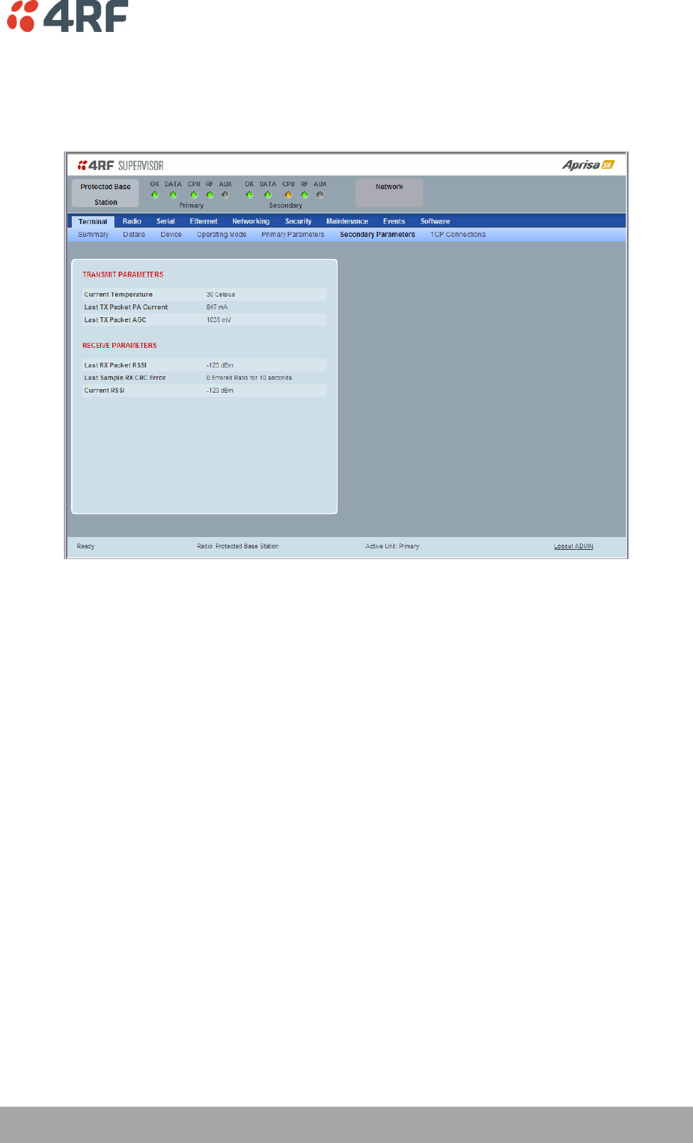
Managing the Radio | 181
Aprisa SR User Manual
Protected Station: Terminal > Secondary Parameters
The Parameters page is a dynamic page that will display the parameters associated with the active
alarms, set on ‘Events > Events Setup’ on page 146. The screenshot below shows a small amount of
monitored alarms as an example.
TRANSMIT / RECEIVE PARAMETERS
This parameter displays the parameters of the Secondary radio.
See ‘Terminal > Parameters’ on page 87 for parameter details.
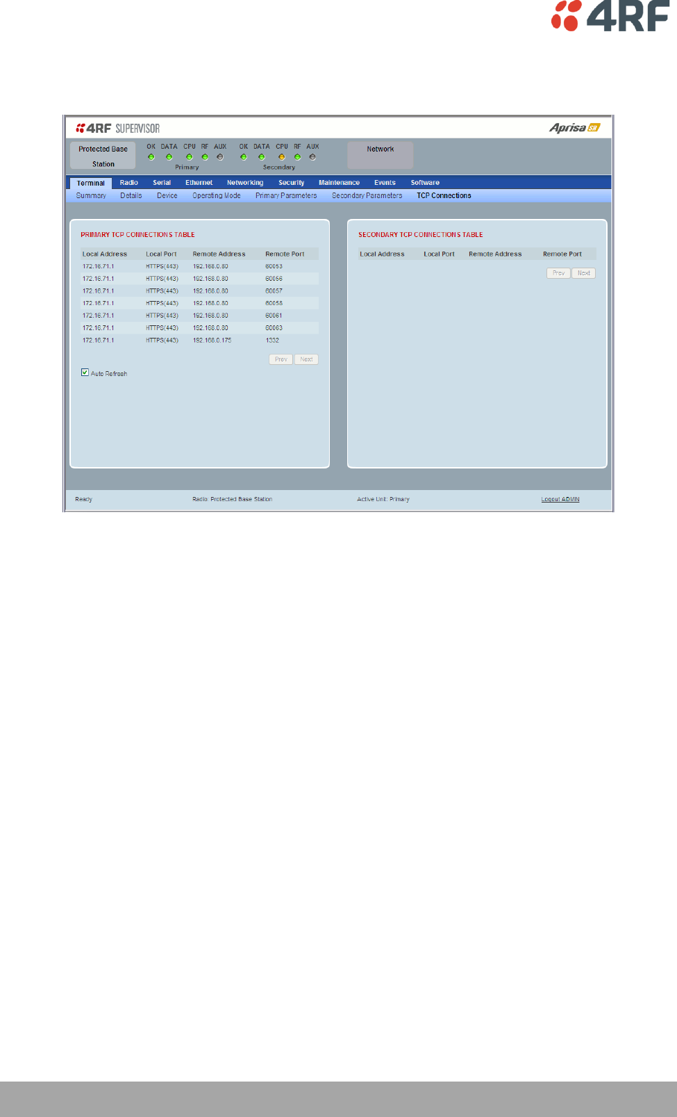
182 | Managing the Radio
Aprisa SR User Manual
Protected Station: Terminal > TCP Connections
The TCP Connections page displays the list of active TCP connections on the radio.
PRIMARY / SECONDARY TCP CONNECTIONS TABLE
The Next button will display the next page of 8 connections and the Prev button will display the previous
page of 8 connections.
If the Auto Refresh option is ticked, the TCP Connections table will refresh every 12 seconds.
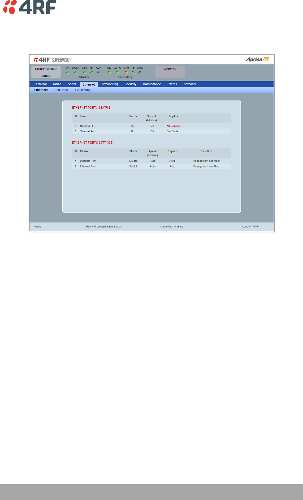
Managing the Radio | 183
Aprisa SR User Manual
Protected Station: Ethernet > Summary
This page displays the current settings for the Protected Station Ethernet port parameters.
See ‘Protected Station: Ethernet > Port Setup’ for configuration options.
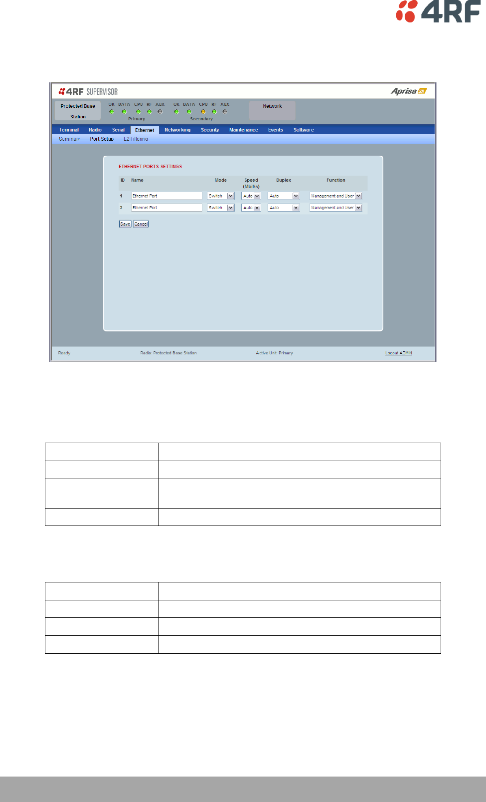
184 | Managing the Radio
Aprisa SR User Manual
Protected Station: Ethernet > Port Setup
This page provides the setup for the Protected Station Ethernet ports settings.
ETHERNET PORT SETTINGS
Mode
This parameter controls the Ethernet traffic flow. The default setting is Standard.
Option
Function
Standard
Enables Ethernet data communication over the radio link.
Switch
Ethernet traffic is switched locally between the two
Ethernet ports and communicated over the radio link
Disabled
Disables Ethernet data communication over the radio link.
Speed (Mbit/s)
This parameter controls the traffic rate of the Ethernet port. The default setting is Auto.
Option
Function
Auto
Provides auto selection of Ethernet Port Speed
10
The Ethernet Port Speed is manualy set to 10 Mbit/s
100
The Ethernet Port Speed is manualy set to 100 Mbit/s

Managing the Radio | 185
Aprisa SR User Manual
Duplex
This parameter controls the transmission mode of the Ethernet port. The default setting is Auto.
Option
Function
Auto
Provides auto selection of Ethernet Port duplex setting.
Half Duplex
The Ethernet Port is manualy set to Half Duplex.
Full Duplex
The Ethernet Port is manualy set to Full Duplex.
Function
This parameter controls the use for the Ethernet port. The default setting is Management and User.
Option
Function
Management Only
The Ethernet port is only used for management of the
network.
Management and User
The Ethernet port is used for management of the network
and User traffic over the radio link.
User Only
The Ethernet port is only used for User traffic over the radio
link.
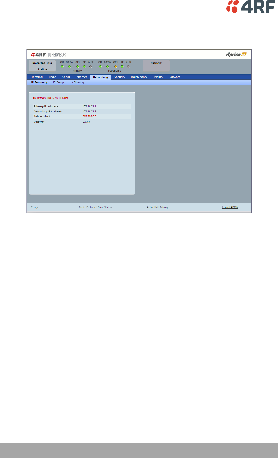
186 | Managing the Radio
Aprisa SR User Manual
Protected Station: Networking > IP Summary
This page displays the current settings for the Protected Station Networking IP settings.
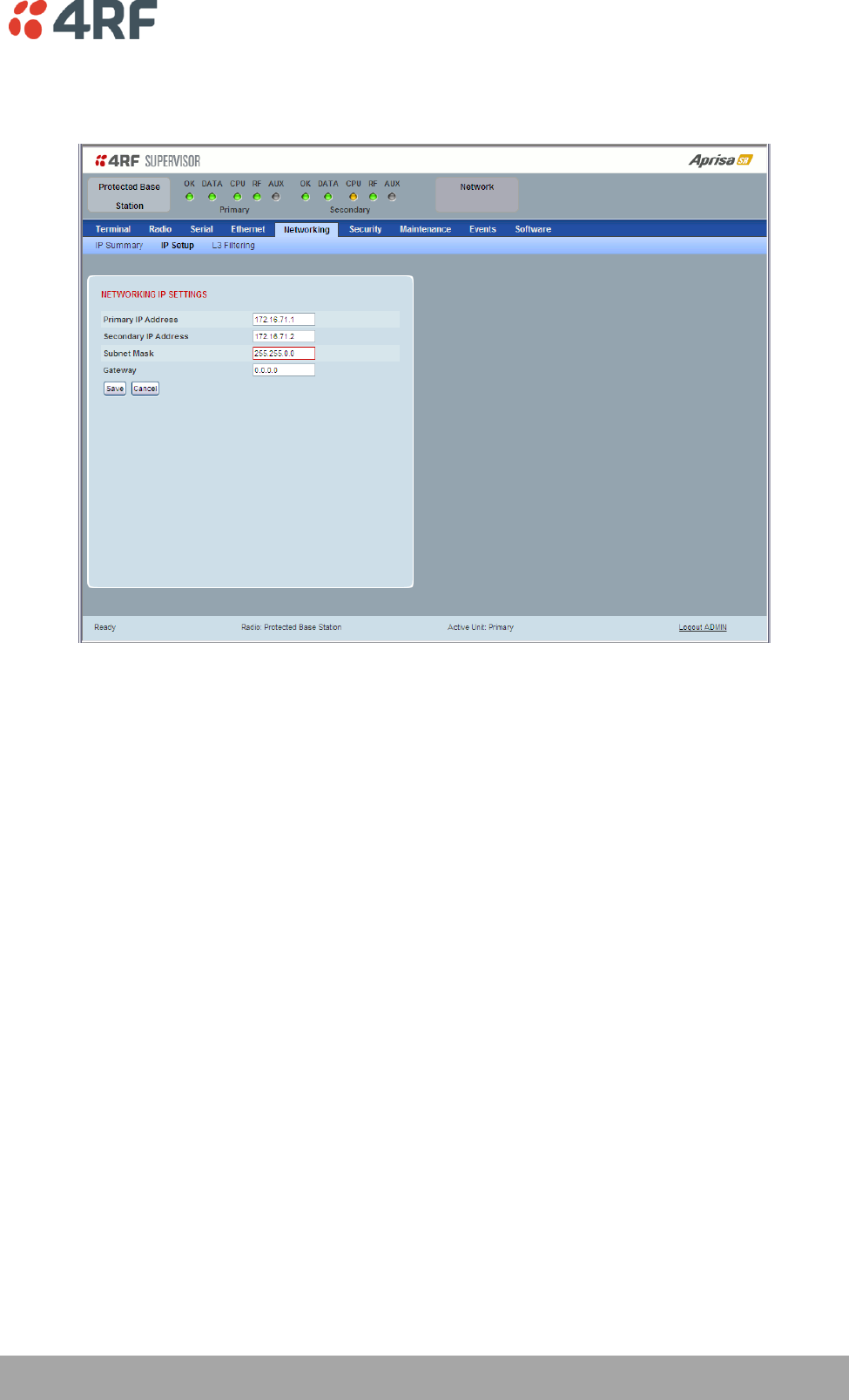
Managing the Radio | 187
Aprisa SR User Manual
Protected Station: Networking > IP Setup
This page provides the setup for the Protected Station Networking IP setup.
NETWORKING IP SETTINGS
Changes in these parameters are automatically changed in the partner radio.
Primary IP Address
Set the static IP Address of the primary radio assigned by your site network administrator using the
standard format xxx.xxx.xxx.xxx. The default IP address is in the range 169.254.50.10.
Secondary IP Address
Set the static IP Address of the secondary radio assigned by your site network administrator using the
standard format xxx.xxx.xxx.xxx. The default IP address is in the range 169.254.50.10.
Subnet Mask
Set the Subnet Mask of the radio using the standard format xxx.xxx.xxx.xxx. The default subnet mask is
255.255.0.0.
Gateway
Set the Gateway address of the radio, if required, using the standard format xxx.xxx.xxx. The default
Gateway is 0.0.0.0.
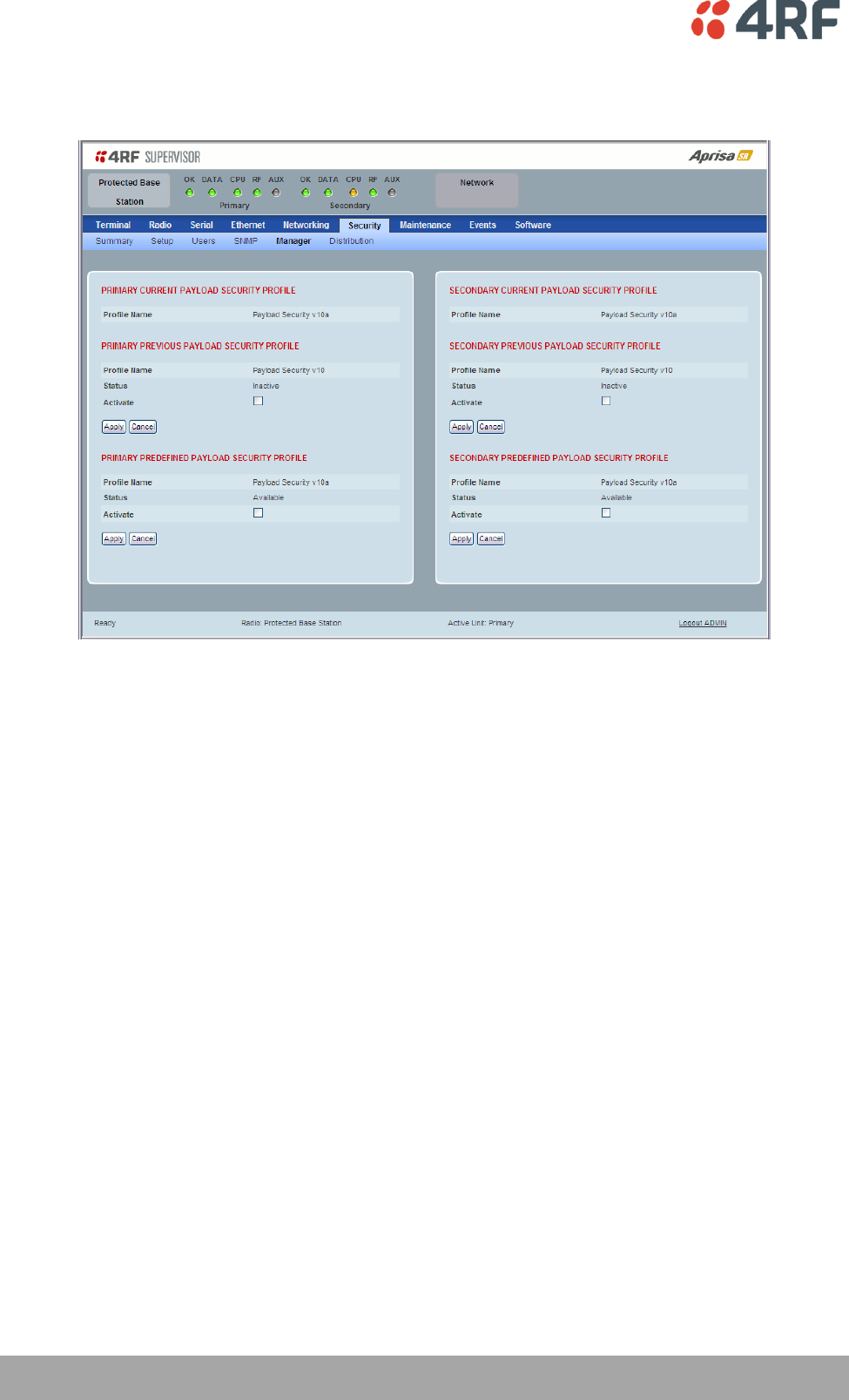
188 | Managing the Radio
Aprisa SR User Manual
Protected Station: Security > Manager
This page provides the management and control of the Protected Station Networking Security settings.
PRIMARY / SECONDARY SECURITY PROFILE
See ‘Security > Manager’ on page 126 for parameter details.
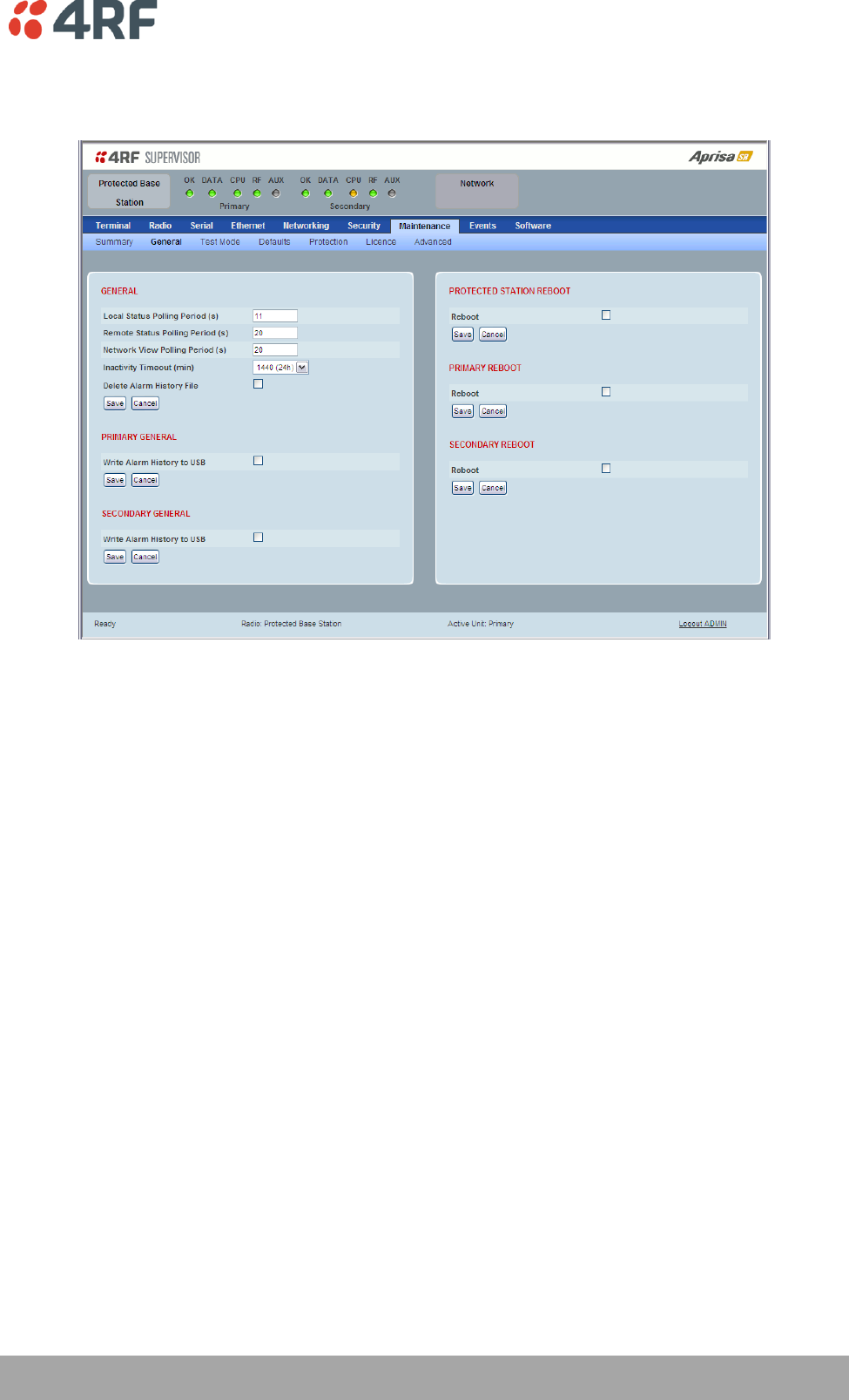
Managing the Radio | 189
Aprisa SR User Manual
Protected Station: Maintenance > General
This page provides the management and control of the Protected Station Maintenance General settings.
See ‘Maintenance > General’ on page 134 for parameter details.
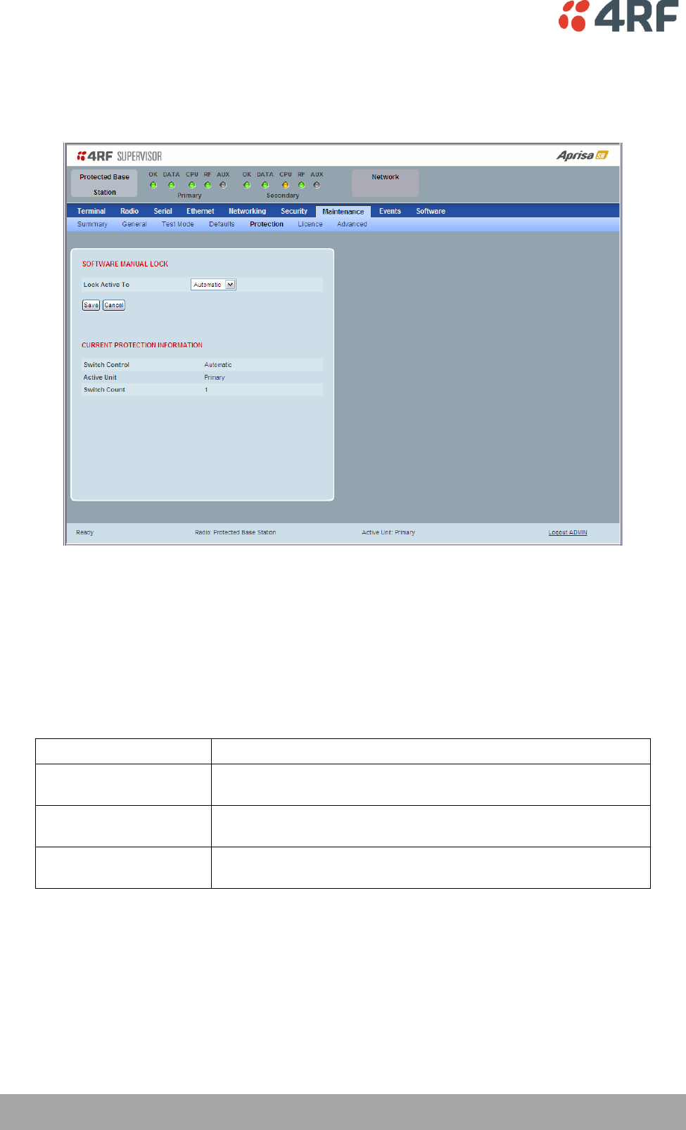
190 | Managing the Radio
Aprisa SR User Manual
Maintenance
Protected Station: Maintenance > Protection
This page provides the management and control of the Protected Station Maintenance Protection settings.
SOFTWARE MANUAL LOCK
The software Manual Lock is a software implementation of the Hardware Manual Lock switch on the
Protection Switch.
Lock Active To
This parameter sets the Protection Switch Software Manual Lock. The Software Manual Lock only operates
if the Hardware Manual Lock is deactivated (set to the Auto position).
Option
Function
Automatic
The protection is automatic and switching will be governed by
normal switching and blocking criteria.
Primary
The primary radio will become active i.e. traffic will be switched
to the primary radio.
Secondary
The secondary radio will become active i.e. traffic will be switched
to the secondary radio.

Managing the Radio | 191
Aprisa SR User Manual
CURRENT PROTECTION INFORMATION
Switch Control
This parameter shows the status of the switch control i.e. which mechanism is in control of the protection
switch.
Option
Function
Automatic
The protection is automatic and switching will be governed by
normal switching and blocking criteria.
Software Manual Lock
The Software Manual Lock has control of the protection switch.
Hardware Manual Lock
The Hardware Manual Lock has control of the protection switch.
Active Unit
This parameter shows the radio which is currently active (Primary or Secondary).
Switch Count
This parameter shows the number of protection switch-overs since the last radio reboot (volatile).
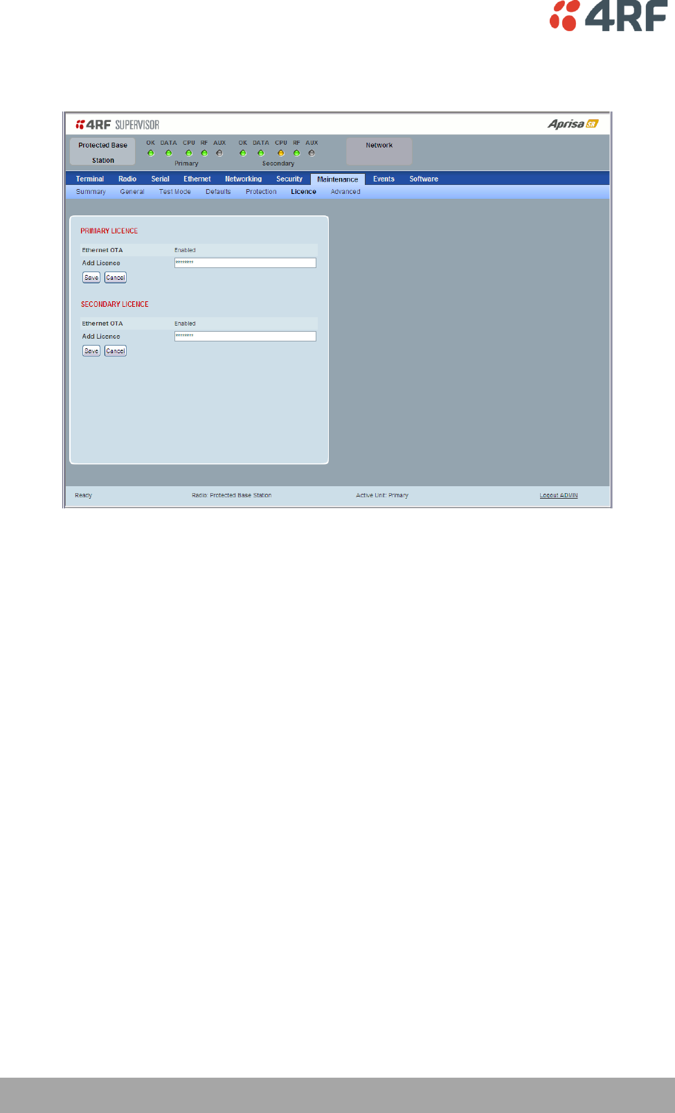
192 | Managing the Radio
Aprisa SR User Manual
Protected Station: Maintenance > Licence
This page provides the management and control of the Protected Station Maintenance Licence settings.
PRIMARY / SECONDARY LICENCE
See ‘Maintenance > Licence’ on page 140 for parameter details.
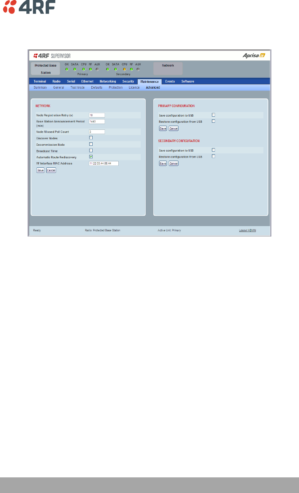
Managing the Radio | 193
Aprisa SR User Manual
Protected Station: Maintenance > Advanced
This page provides the management and control of the Protected Station Maintenance Advanced settings.
NETWORK
See ‘Maintenance > Advanced’ on page 141 for parameter details.
PRIMARY / SECONDARY CONFIGURATION
See ‘Maintenance > Advanced’ on page 141 for parameter details.
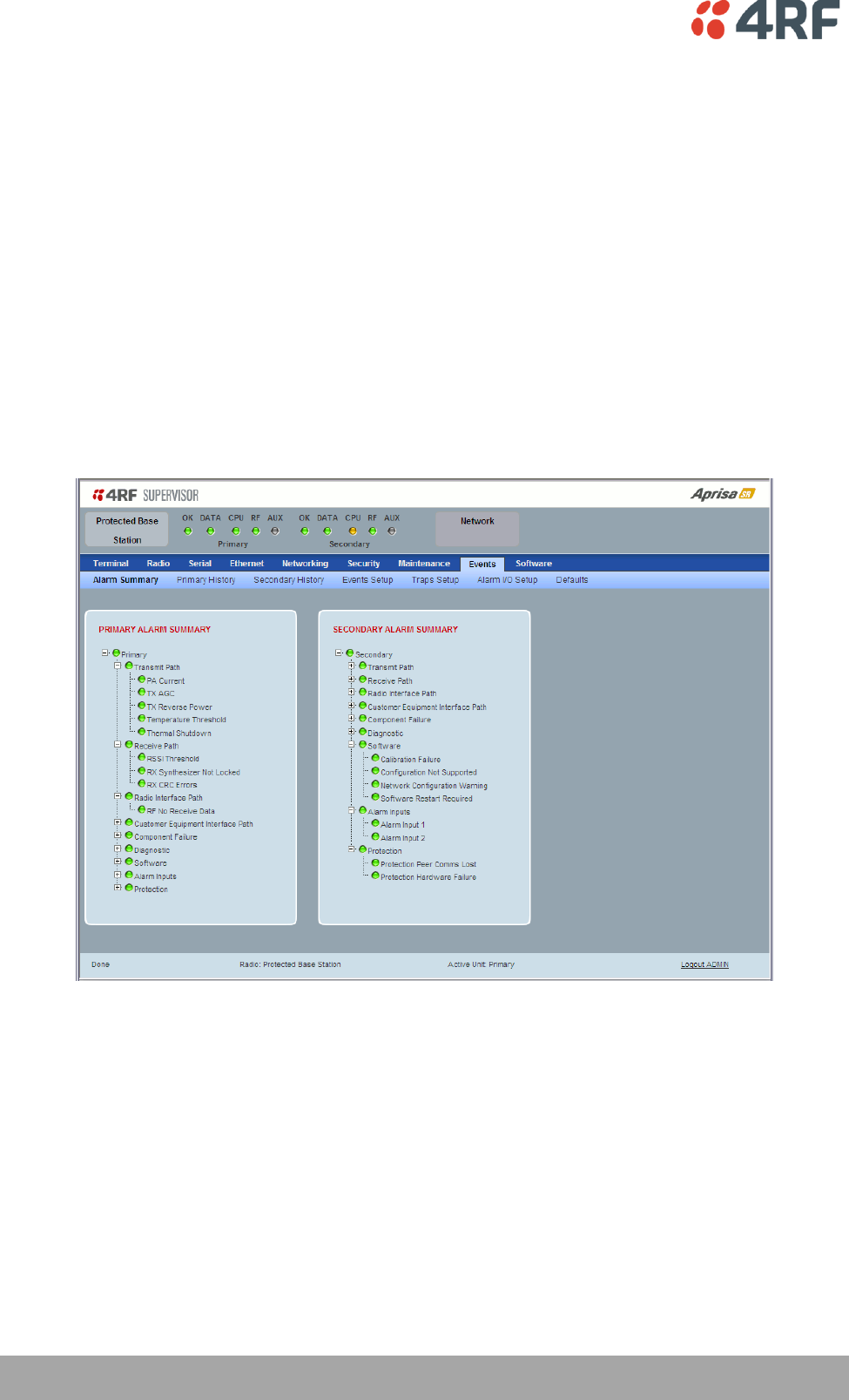
194 | Managing the Radio
Aprisa SR User Manual
Events
The Events menu contains the setup and management of the alarms, alarm events and traps.
Protected Station: Events > Alarm Summary
There are two types of events that can be generated on the Aprisa SR radio. These are:
1. Alarm Events
Alarm Events are generated to indicate a problem on the radio.
2. Informational Events
Informational Events are generated to provide information on key activities that are occurring on the
radio. These events do not indicate an alarm on the radio and are used to provide information only.
See ‘Alarm Types and Sources’ on page 228 for a complete list of events.
PRIMARY / SECONDARY ALARM SUMMARY
See ‘Events > Alarm Summary’ on page 144 for parameter details.
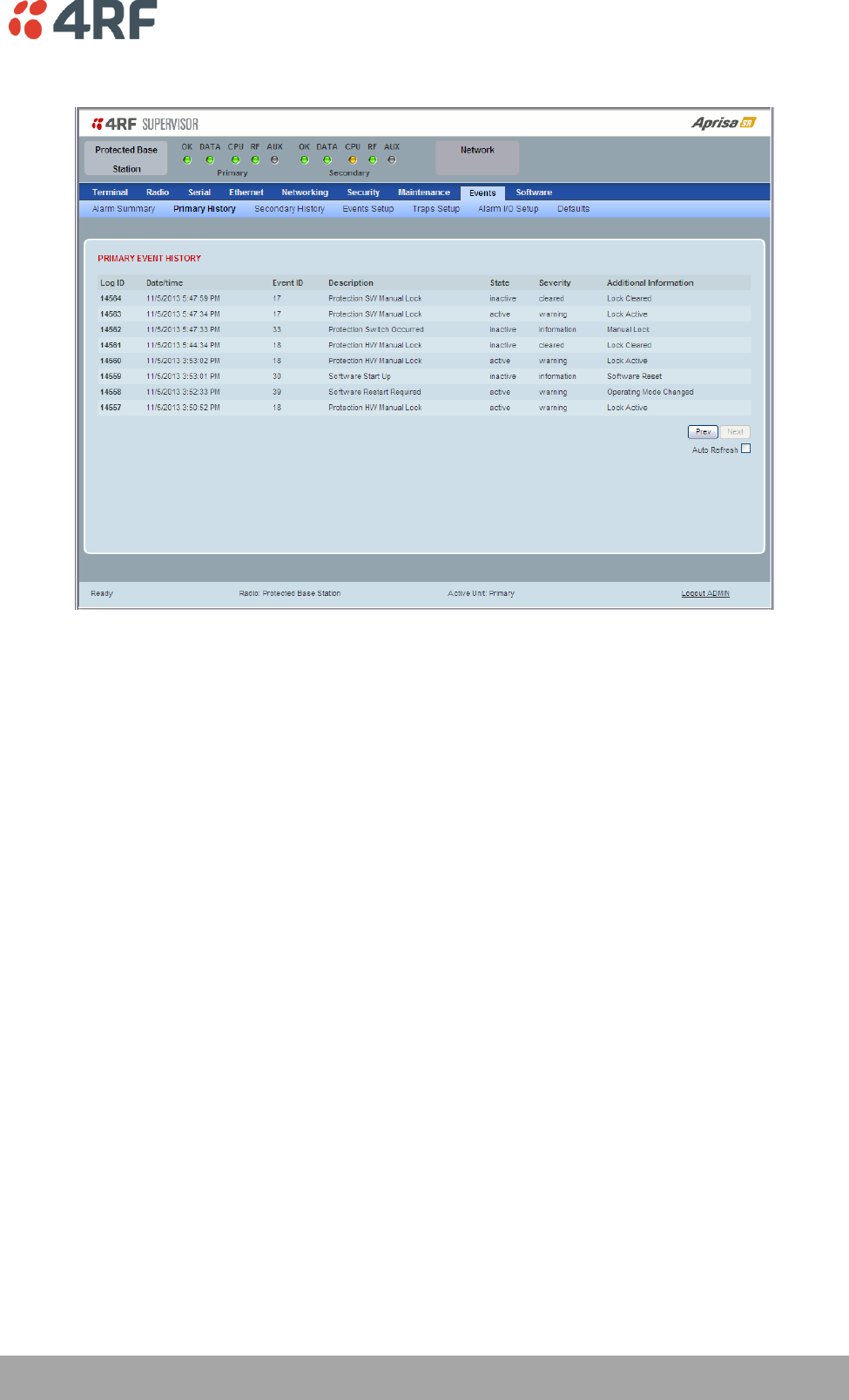
Managing the Radio | 195
Aprisa SR User Manual
Protected Station: Events > Primary History
PRIMARY EVENT HISTORY
See ‘Events > Event History’ on page 145 for parameter details.
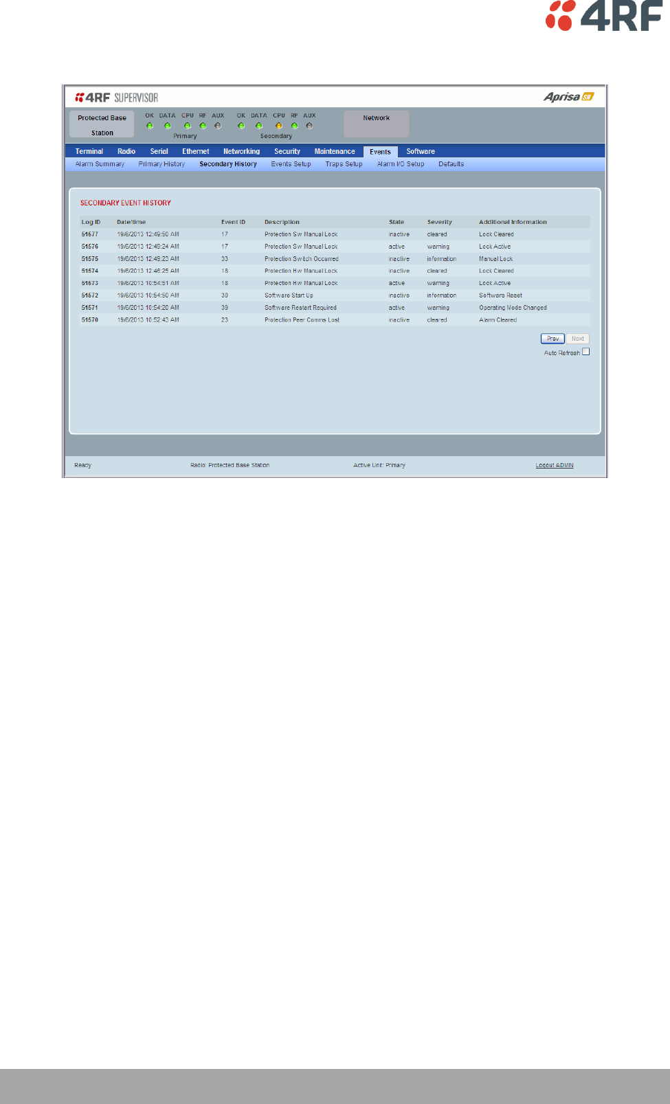
196 | Managing the Radio
Aprisa SR User Manual
Protected Station: Events > Secondary History
SECONDARY EVENT HISTORY
See ‘Events > Event History’ on page 145 for parameter details.

Managing the Radio | 197
Aprisa SR User Manual
Software
The Software menu contains the setup and management of the system software including network
software distribution and activation on a protected station.
Single Radio Software Upgrade
The radio software can be upgraded on a single radio single Aprisa SR radio (see ‘Single Radio Software
Upgrade’ on page 223). This process would only be used if the radio was a replacement or a new station in
an existing network.
Network Software Upgrade
The radio software can be upgraded on an entire Aprisa SR radio network remotely over the radio link (see
‘Network Software Upgrade’ on page 222). This process involves the following steps:
1. Transfer the new software to base station primary radio with ‘Protected Station: Software > Primary
File Transfer’.
2. File Transfer the new software to base station secondary radio with ‘Protected Station: Software >
Secondary File Transfer’.
3. Using the Software Manual Lock, manually lock all protected remotes to the currently active radio
(this is necessary to prevent automatic switching during the distribution and activation process).
4. Distribute the new software to all remote stations with ‘Protected Station: Software > Remote
Distribution’. Note: The software pack in the base station active radio is used for distribution.
5. Activate of the new software on remote stations with ‘Protected Station: Software > Remote
Activation’.
6. Finally, activate the new software on the base station primary and secondary radios. Note: activating
the software will reboot the radio which will reset the Software Manual Lock to Automatic.
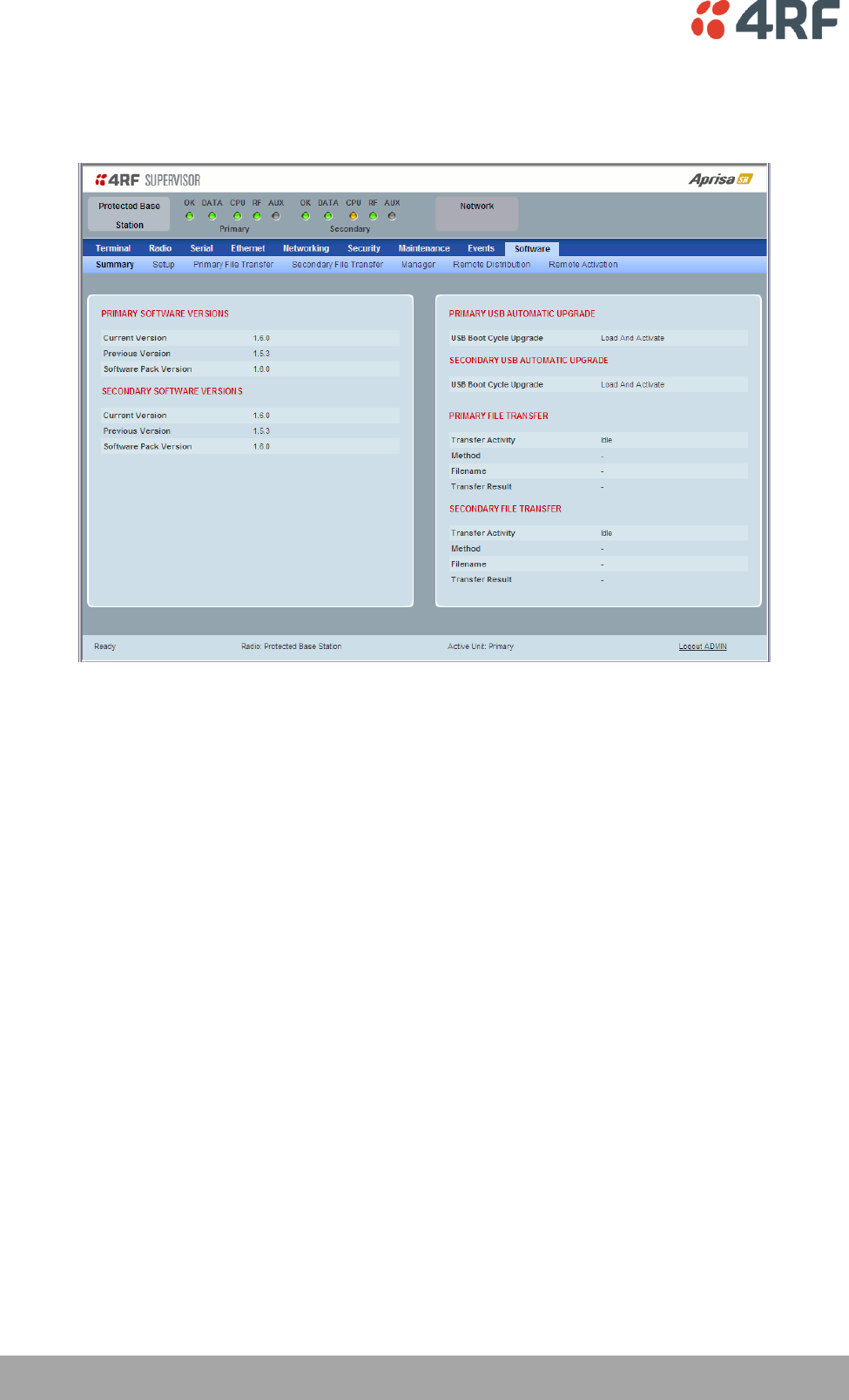
198 | Managing the Radio
Aprisa SR User Manual
Protected Station: Software > Summary
This page provides a summary of the software versions installed on the radio, the setup options and the
status of the File Transfers.
PRIMARY / SECONDARY SOFTWARE VERSIONS
See ‘Protected Station: Software > Primary File Transfer’ and ‘Protected Station: Software > Secondary
File Transfer’ for parameter details.
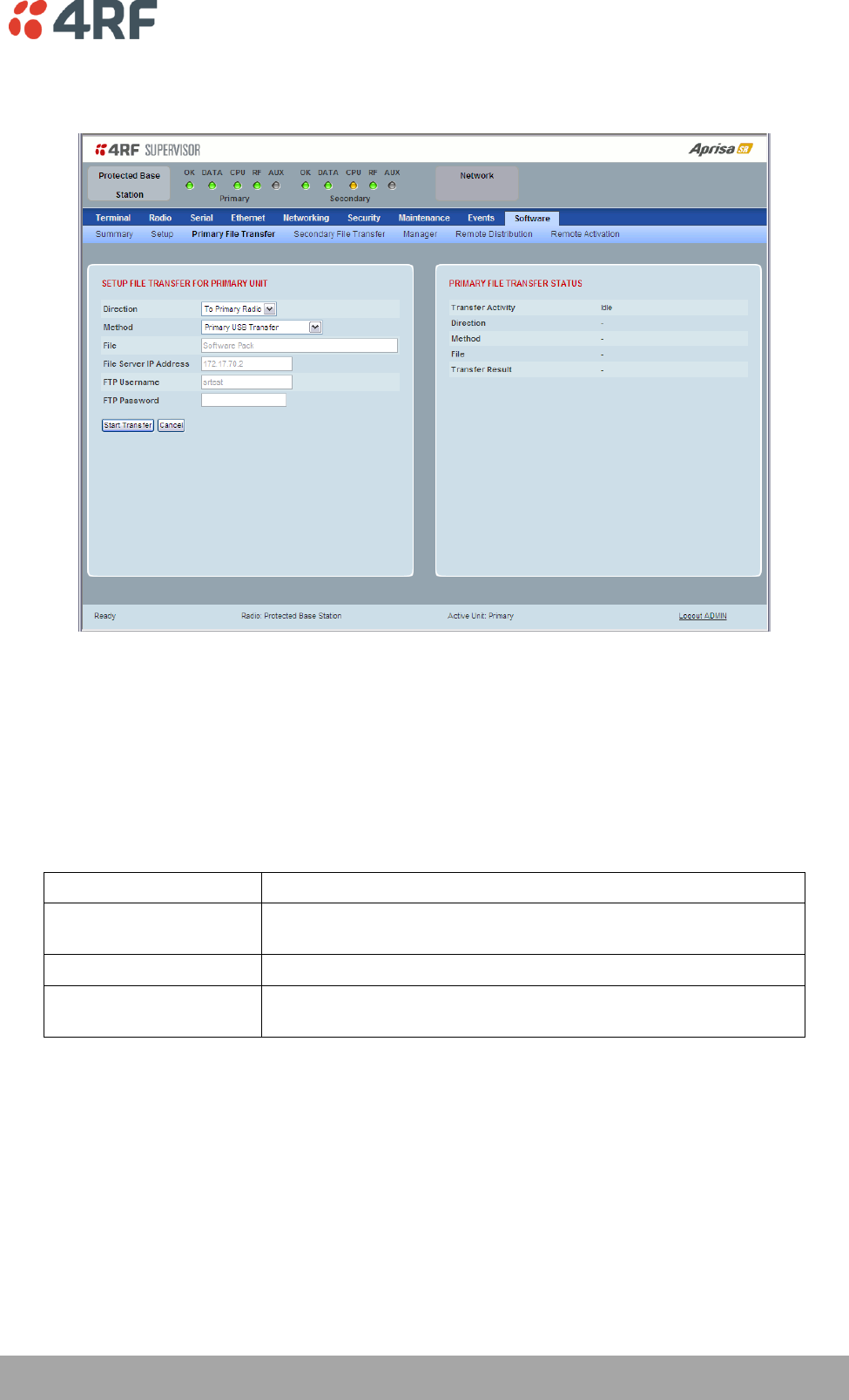
Managing the Radio | 199
Aprisa SR User Manual
Protected Station: Software > Primary File Transfer
This page provides the mechanism to transfer new software from a file source into the primary radio.
SETUP FILE TRANSFER FOR PRIMARY UNIT
Direction
This parameter sets the direction of file transfer. In this software version, the only choice is ‘To Primary
Radio’.
Method
This parameter sets the method of file transfer.
Option
Function
Primary USB Transfer
Transfers the software from the USB flash drive to the primary
radio.
FTP
Transfers the software from an FTP server to the primary radio.
Transfer from Secondary
Unit
Transfers the software from the secondary radio to the primary
radio.
PRIMARY FILE TRANSFER STATUS
See ‘Software > File Transfer’ on page 156 for parameter details.
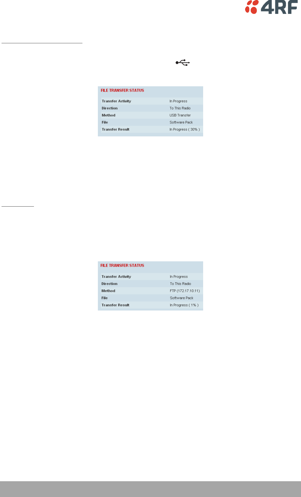
200 | Managing the Radio
Aprisa SR User Manual
To transfer software into the Aprisa SR primary radio:
Primary USB Transfer Method
1. Unzip the software release files in to the root directory of a USB flash drive.
2. Insert the USB flash drive into the primary radio Host Port .
3. Click on ‘Start Transfer’.
4. When the transfer is completed, remove the USB flash drive from the primary radio Host Port. If the
SuperVisor ‘USB Boot Upgrade’ setting is set to ‘Disabled’ (see ‘USB Boot Upgrade’ on page 155), the
USB flash drive doesn’t need to be removed as the radio won’t try to load from it.
5. Go to ‘Protected Station: Software > Manager’ on page 205 to activate the Software Pack. The radio
will reboot automatically.
FTP Method
1. Unzip the software release files in to a temporary directory.
2. Open the FTP server and point it to the temporary directory.
3. Enter the FTP server IP address, Username and password into SuperVisor.
4. Click on ‘Start Transfer’.
5. Go to ‘Protected Station: Software > Manager’ on page 205 to activate the Software Pack. The radio
will reboot automatically.

Managing the Radio | 201
Aprisa SR User Manual
Transfer from Secondary Unit
1. Select Transfer from Secondary Unit.
2. Click on ‘Start Transfer’.
3. Go to ‘Protected Station: Software > Manager’ on page 205 to activate the Software Pack. The radio
will reboot automatically.
If the file transfer fails, check the Event History page (see ‘Protected Station: Events > Secondary History’
on page 196) for more details of the transfer.
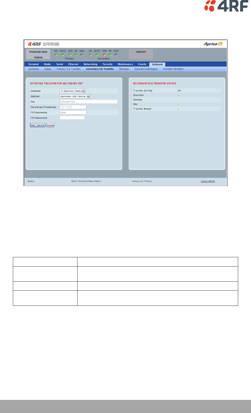
202 | Managing the Radio
Aprisa SR User Manual
Protected Station: Software > Secondary File Transfer
This page provides the mechanism to transfer new software from a file source into the secondary radio.
SETUP FILE TRANSFER FOR SECONDARY UNIT
Direction
This parameter sets the direction of file transfer. In this software version, the only choice is ‘To Secondary
Radio’.
Method
This parameter sets the method of file transfer.
Option
Function
Secondary USB Transfer
Transfers the software from the USB flash drive to the secondary
radio.
FTP
Transfers the software from an FTP server to the secondary radio.
Transfer from Primary
Unit
Transfers the software from the primary radio to the secondary
radio.
SECONDARY FILE TRANSFER STATUS
See ‘Software > File Transfer’ on page 156 for parameter details.
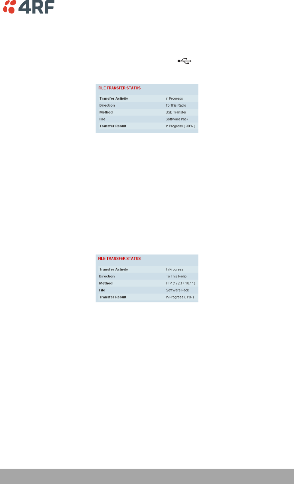
Managing the Radio | 203
Aprisa SR User Manual
To transfer software into the Aprisa SR secondary radio:
Secondary USB Transfer Method
1. Unzip the software release files in to the root directory of a USB flash drive.
2. Insert the USB flash drive into the secondary radio Host Port .
3. Click on ‘Start Transfer’.
4. When the transfer is completed, remove the USB flash drive from the secondary radio Host Port. If the
SuperVisor ‘USB Boot Upgrade’ setting is set to ‘Disabled’ (see ‘USB Boot Upgrade’ on page 155), the
USB flash drive doesn’t need to be removed as the radio won’t try to load from it.
5. Go to ‘Protected Station: Software > Manager’ on page 205 to activate the Software Pack. The radio
will reboot automatically.
FTP Method
1. Unzip the software release files in to a temporary directory.
2. Open the FTP server and point it to the temporary directory.
3. Enter the FTP server IP address, Username and password into SuperVisor.
3. Click on ‘Start Transfer’.
4. Go to ‘Protected Station: Software > Manager’ on page 205 to activate the Software Pack. The radio
will reboot automatically.

204 | Managing the Radio
Aprisa SR User Manual
Transfer from Primary Unit
1. Select Transfer from Primary Unit.
2. Click on ‘Start Transfer’.
3. Go to ‘Protected Station: Software > Manager’ on page 205 to activate the Software Pack. The radio
will reboot automatically.
If the file transfer fails, check the Event History page (see ‘Protected Station: Events > Primary History’ on
page 195) for more details of the transfer.
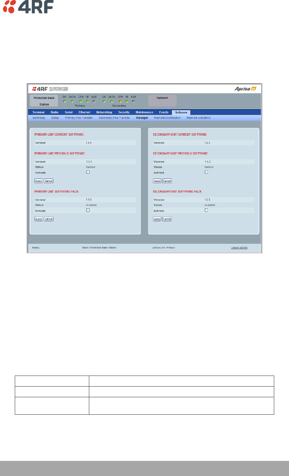
Managing the Radio | 205
Aprisa SR User Manual
Protected Station: Software > Manager
This page summaries and manages the software versions available in the primary and secondary radios.
The manager is predominantly used to activate new software on single radios. Network activation is
performed with ‘Protected Station: Software > Remote Activation’.
Both the previous software (if available) and Software Pack versions can be activated on each radio from
this page.
PRIMARY / SECONDARY CURRENT SOFTWARE
Version
This parameter displays the software version running on the radio.
PRIMARY / SECONDARY PREVIOUS SOFTWARE
Version
This parameter displays the software version that was running on the radio prior to the current software
being activated.
Status
This parameter displays the status of the software version running on the radio.
Option
Function
Active
The software is operating the radio.
Inactive
The software is not operating the radio but could be re-activated if
required.

206 | Managing the Radio
Aprisa SR User Manual
PRIMARY / SECONDARY SOFTWARE PACK
Version
This parameter displays the software pack version available for distribution on base station and activate
on all stations.
Status
This parameter displays the status of the software pack version.
Option
Function
Available
On the base station, the software pack is available for distribution.
On all stations, the software pack is available for activation.
Activating
The software pack is activating in the radio.
Unavailable
There is no software pack loaded into the radio.
Activate
This parameter activates the software pack.
The Aprisa SR will automatically reboot after activation.
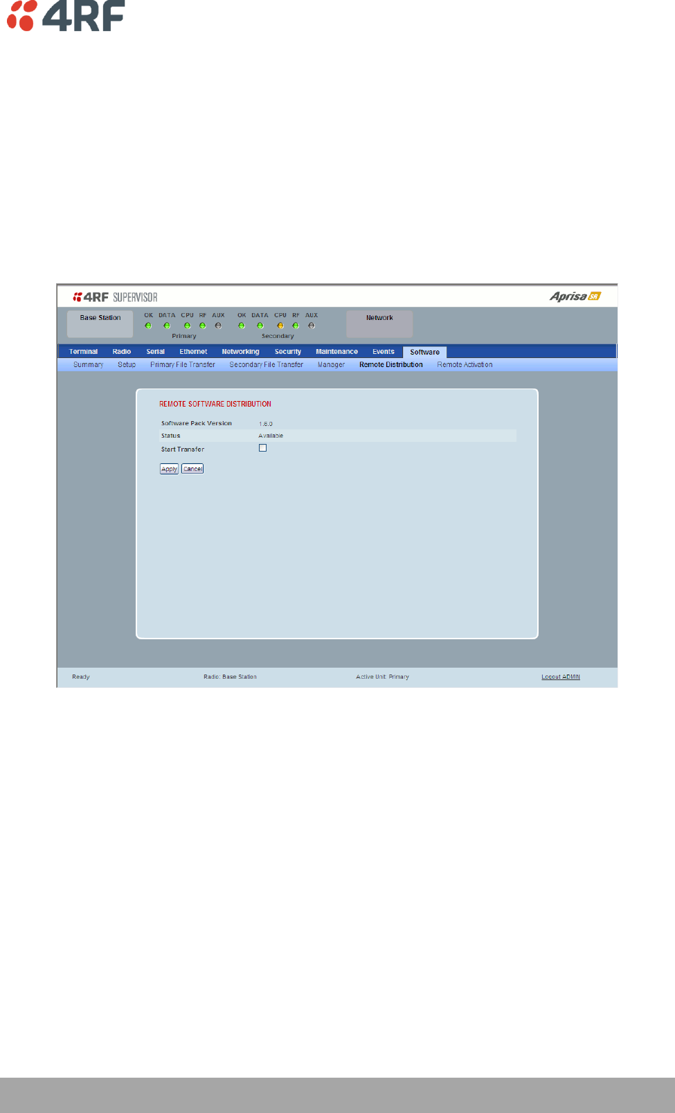
Managing the Radio | 207
Aprisa SR User Manual
Protected Station: Software > Remote Distribution
This page provides the mechanism to distribute software to all remote protected stations into the Aprisa
SR network (network) and then activate it.
The Software Pack loaded into the base station with the file transfer process (see ‘Protected Station:
Software > Primary File Transfer’ on page 199) is distributed via the radio link to all remote stations from
the active radio.
The distribution process is monitored from this page.
When all remote stations receive the Software Pack version, the software can be remotely activated on all
remote stations.
This page is only available when the radio is configured as a Base Station.
REMOTE SOFTWARE DISTRIBUTION
Software Pack Version
This parameter displays the software pack version available for distribution on base station and activate
on all stations.
Status
This parameter displays the status of the software pack version.
If a Software Pack is not available, the status will display ‘Unavailable’ and the software distribution
mechanism will not work.
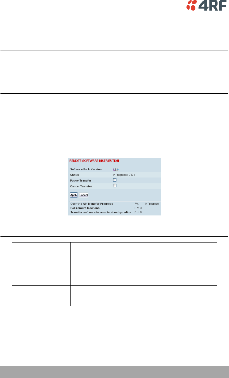
208 | Managing the Radio
Aprisa SR User Manual
Start Transfer
This parameter when activated distributes (broadcasts) the new Software Pack to all remote stations in
the network.
Note: The distribution of software to remote stations does not stop customer traffic from being
transferred. However, due to the volume of traffic, the software distribution process may affect customer
traffic.
Software distribution traffic is classified as ‘management traffic’ but does not use the Ethernet
management priority setting. Software distribution traffic priority has a fixed priority setting of ‘very
low’.
To distribute software to remote stations:
This process assumes that a Software Pack has been loaded into the base station with the file transfer
process (see ‘Protected Station: Software > Primary File Transfer’ on page 199).
1. To ensure that the Network Table is up to date, it is recommended running the node discover function
(see ‘Discover Nodes’ on page 142).
2. Click on ‘Start Transfer’.
Note: This process could take anywhere between 40 minutes and several hours depending on channel size,
Ethernet Management Priority setting and the amount of customer traffic on the network.
Result
Function
Over the Air Transfer
Progress
The percentage of the software pack that has been broadcast to
the remote radios.
Poll Remote Locations
X is the number of radios polled to determine the number of
standby radios.
Y is the number of remote radios registered with the base station.
Transfer software to
remote standby radios
X is the number of standby radios with the new software version.
Y is the number of standby radios requiring the new software
version.
3. When the distribution is completed, activate the software with the Remote Software Activation.
Pause Transfer
This parameter when activated, pauses the Over the Air Transfer Process and shows the distribution
status. The distribution process will continue from where it was paused with Resume Transfer.

Managing the Radio | 209
Aprisa SR User Manual
Cancel Transfer
This parameter when activated, cancels the Over the Air Transfer Process immediately.
During the distribution process, it is possible to navigate away from this page and come back to it to check
progress. The SuperVisor session will not timeout.
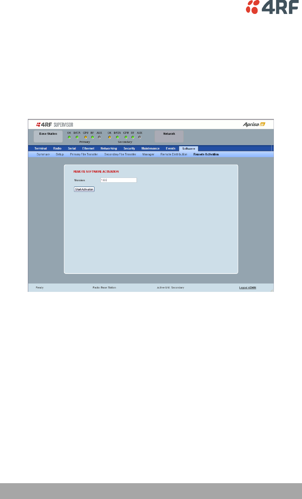
210 | Managing the Radio
Aprisa SR User Manual
Protected Station: Software > Remote Activation
This page provides the mechanism to activate software on all remote protected stations.
The Software Pack has been loaded into the base station with the file transfer process (see ‘Protected
Station: Software > Primary File Transfer’ on page 199) and distributed via the radio link to all remote
stations from the active radio.
When all remote stations receive the Software Pack version, the software can be remotely activated on all
remote stations.
The activation process is monitored by this page.
This page is only available when the radio is configured as a Base Station.
REMOTE SOFTWARE ACTIVATION
When the software pack version has been distributed to all the remote stations, the software is then
activated in all the remote stations with this command. If successful, then activate the software pack in
the base station to complete the network upgrade.
Version
This parameter displays the software version for activation. The default version is the software pack
version but any valid software version can be entered in the format ‘n.n.n’.
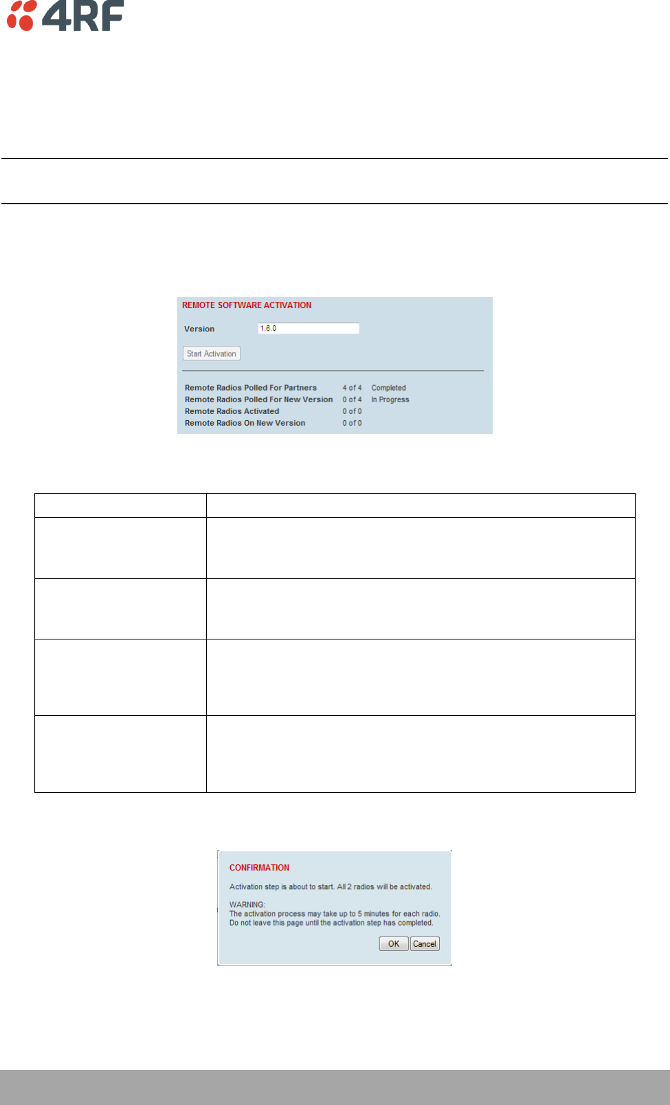
Managing the Radio | 211
Aprisa SR User Manual
To activate software in remote stations:
This process assumes that a Software Pack has been loaded into the base station with the file transfer
process (see ‘Software > File Transfer’ on page 156) and that distributed to all remote radios in the
network.
Note: Do not navigate SuperVisor away from this page during the activation process (SuperVisor can lose
PC focus).
1. Enter the Software Pack version (if different from displayed version).
2. Click on ‘Start Activation’.
The remote stations will be polled to determine which radios require activation:
Result
Function (X of Y)
Remote Radios Polled for
Partners
X is the number of radios polled to determine the number of
protected stations in the network.
Y is the number of remote radios registered with the base station.
Remote Radios Polled for
New Version
X is the number of radios polled to determine the number of radios
that contain the new software version.
Y is the number of remote radios registered with the base station.
Remote Radios Activated
X is the number of radios that contain the new software version
and have been activated.
Y is the number of radios that contain the new software version
and can be activated.
Remote Radios On New
Version
X is the number of radios that has been successfully activated and
now running the new version of software.
Y is the number of radios that the activation command was
executed on.
When the activation is ready to start:
3. Click on ‘OK’ to start the activation process or Cancel to quit.
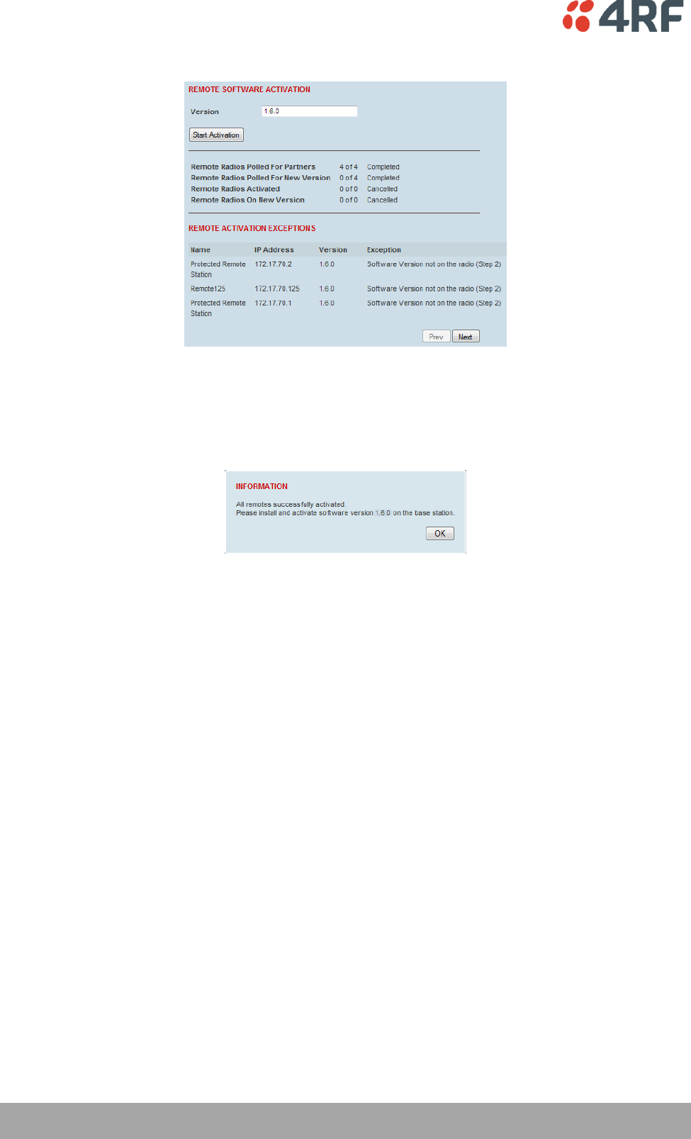
212 | Managing the Radio
Aprisa SR User Manual
The page will display the progress of the activation.
The example shows that during the activation process there were exceptions that may need to be
investigated.
When all the remote radios have been activated, the base station radio must now be activated with (see
‘Software > Manager’ on page 159).
4. Click on ‘OK’ to start the activation on the base station.
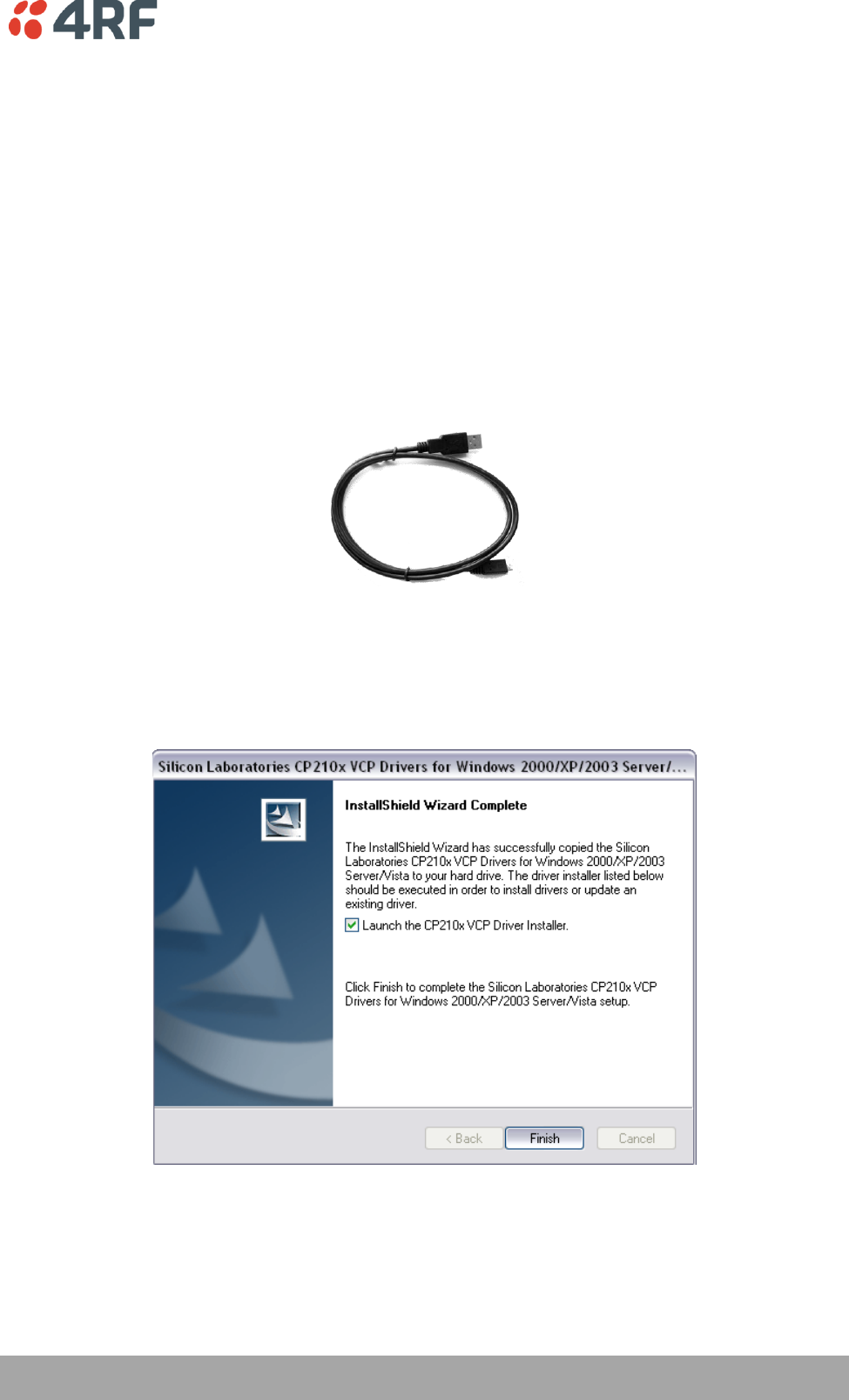
Managing the Radio | 213
Aprisa SR User Manual
Command Line Interface
The Aprisa SR has a Command Line Interface (CLI) which provides basic product setup and configuration.
This can be useful if you need to confirm the radio’s IP address, for example.
You can password-protect the Command Line Interface to prevent unauthorized users from modifying
radio settings.
This interface can be accessed via an Ethernet Port (RJ45) or the Management Port (USB micro type B).
Connecting to the Management Port
A USB Cable USB A to USB micro B, 1m is provided with each radio.
1. Connect the USB A to your computer USB port and the USB micro B to the management port of the
Aprisa SR (MGMT).
2. Unzip and install the USB Serial Driver CP210x_VCP_Win2K_XP_S2K3.zip on your computer. This file is
on the Information and setup CD supplied with the radio.
3. Go to your computer device manager (Control Panel > System > Hardware > Device Manager)
4. Click on ‘Ports (COM & LPT)’
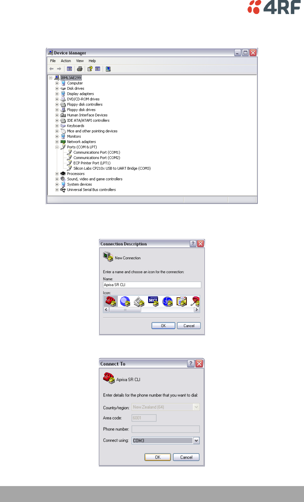
214 | Managing the Radio
Aprisa SR User Manual
5. Make a note of the COM port which has been allocated to the ‘Silicon Labs CP210x USB to UART
Bridge’ (COM3 in the example below)
6. Open HyperTerminal Session (Start > All Programs > Accessories > Communications > HyperTerminal)
7. Enter a name for the connection (Aprisa SR CLI for example) and click OK.
8. Select the COM port from the Connect Using drop-down box that was allocated to the UART USB.
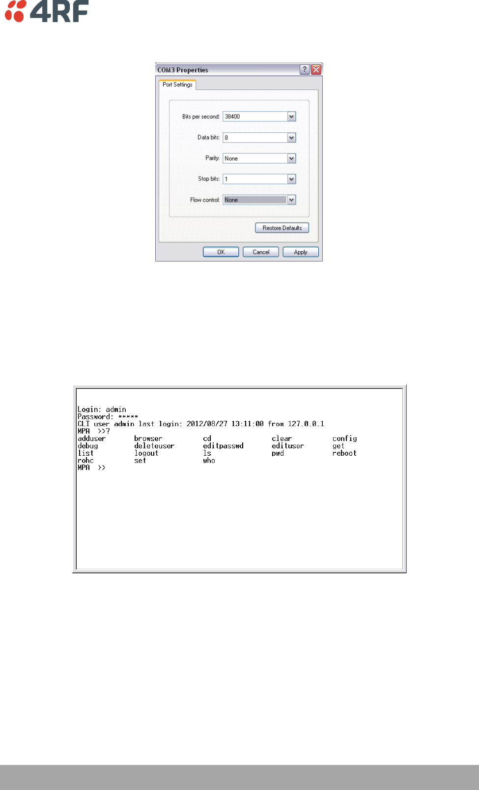
Managing the Radio | 215
Aprisa SR User Manual
9. Set the COM port settings as follows:
10. Click OK. The HyperTerminal window will open.
11. Press the Enter key to initiate the session.
12. Login to the Aprisa SR CLI with a default Username ‘admin’ and Password ‘admin’.
The Aprisa MIB menu is shown:
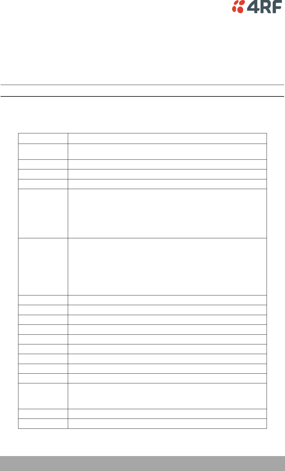
216 | Managing the Radio
Aprisa SR User Manual
CLI Commands
To enter a CLI command:
1. Type the first few characters of the command and hit Tab. This auto completes the command.
2. Enter the command string and enter.
Note: All CLI commands are case sensitive.
The top level CLI command list is displayed by typing a ? at the command prompt.
The following is a list of the top level CLI commands and their usage:
CLI Command
Usage
adduser
adduser [-g <password aging>] [-a <account aging>] [-i <role>] <userName>
<userPassword>
browser
browser <state(STR)>
cd
cd <changeMode(STR)>
clear
Clears the screen
config
config
userdefault
save
restore
factorydefault
restore
debug
set subsystem param(INT) level param(INT)
get
clear subsystem param(INT) level param(INT)
help
log
dump
clear
deleteuser
deleteuser <userName>
editpasswd
editpasswd <oldpassword> <newpassword>
edituser
edituser [-p <password>] [-g <password aging>] [-a <account aging>] [-i]
get
get [-m <mib name>] [-n <module name>] <attribute name> [indexes]
list
list <tablename>
logout
Logs out from the CLI
ls
Displays the next level menu items
pwd
Displays the current working directory
reboot
Reboots the radio
rohc
stats
show
clear
set
set [-m <mib name> ] [-n <module name>] <attribute name> <attribute set v]
who
Shows the users currently logged into the radio
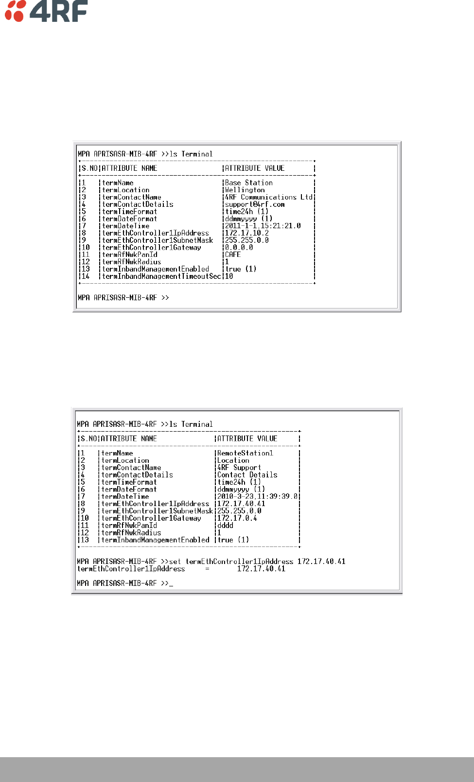
Managing the Radio | 217
Aprisa SR User Manual
Viewing the CLI Terminal Summary
At the command prompt, type:
MPA >>cd APRISASR-MIB-4RF
MPA APRISASR-MIB-4RF >>ls Terminal
Changing the Radio IP Address with the CLI
At the command prompt, type ‘set termEthController1IpAddress xxx.xxx.xxx.xxx’

218 | Managing the Radio
Aprisa SR User Manual
In-Service Commissioning
Before You Start
When you have finished installing the hardware, RF and the traffic interface cabling, the system is ready
to be commissioned. Commissioning the radio is a simple process and consists of:
1. Powering up the radios.
2. Configuring all radios in the network using SuperVisor.
3. Aligning the antennas.
4. Testing that the links are operating correctly.
5. Connecting up the client or user interfaces.
What You Will Need
Appropriately qualified commissioning staff at both ends of each link.
Safety equipment appropriate for the antenna location at both ends of each link.
Communication equipment, that is, mobile phones or two-way radios.
SuperVisor software running on an appropriate laptop, computer, or workstation at the base
station radio.
Tools to facilitate loosening and re-tightening the antenna pan and tilt adjusters.
Predicted receiver input levels and fade margin figures from the radio link budget.

Managing the Radio | 219
Aprisa SR User Manual
Antenna Alignment
A base station omni directional collinear antenna has a vertical polarization. The remote station yagi
antennas must also have vertical polarization.
Aligning the Antennas
Align the remote station yagi antennas by making small adjustments while monitoring the RSSI. The Aprisa
SR has a Test Mode which presents a real time visual display of the RSSI on the front panel LEDs. This can
be used to adjust the antenna for optimum signal strength (see ‘Test Mode’ on page 28).
Note: Low gain antennas need less adjustment in elevation as they are simply aimed at the horizon. They
should always be panned horizontally to find the peak signal.
1. Press and hold the ENTER button on the radio LED panel until all the LEDs flash green (about 3 - 5
seconds).
Note: The time for the LEDs to display the RSSI result is variable, depending on the network traffic,
and can be up to 5 seconds. Small antenna adjustments should be made and then wait for the display
to refresh.
The RSSI poll refresh rate can be set with the SuperVisor command ‘Transmit Period’ (see
‘Maintenance > Test Mode’ on page 137).
2. Move the antenna through a complete sweep horizontally (pan). Note down the RSSI reading for all the
peaks in RSSI that you discover in the pan.
3. Move the antenna to the position corresponding to the maximum RSSI value obtained during the pan.
Move the antenna horizontally slightly to each side of this maximum to find the two points where the
RSSI drops slightly.
4. Move the antenna halfway between these two points and tighten the clamp.
5. If the antenna has an elevation adjustment, move the antenna through a complete sweep (tilt)
vertically. Note down the RSSI reading for all the peaks in RSSI that you discover in the tilt.
6. Move the antenna to the position corresponding to the maximum RSSI value obtained during the tilt.
Move the antenna slightly up and then down from the maximum to find the two points where the RSSI
drops slightly.
7. Move the antenna halfway between these two points and tighten the clamp.
8. Recheck the pan (steps 2-4) and tighten all the clamps firmly.
9. To exit Test Mode, press and hold the ENTER button until all the LEDs flash red (about 3 – 5 seconds).

Maintenance | 221
Aprisa SR User Manual
9. Maintenance
No User-Serviceable Components
There are no user-serviceable components within the radio.
All hardware maintenance must be completed by 4RF or an authorized service centre.
Do not attempt to carry out repairs to any boards or parts.
Return all faulty radios to 4RF or an authorized service centre.
For more information on maintenance and training, please contact 4RF Customer Services at
support@4rf.com.
CAUTION: Electro Static Discharge (ESD) can damage or destroy the sensitive electrical components in the
radio.

222 | Maintenance
Aprisa SR User Manual
Radio Software Upgrade
A software upgrade can be performed on a single radio or an entire Aprisa SR network (network).
Network Software Upgrade
This process allows customers to upgrade their Aprisa SR network from the central base station location
without need for visiting remote sites.
The Software Pack is loaded into the base station with the file transfer process (see ‘Software > File
Transfer’ on page 156) and distributed via the radio link to all remote stations.
When all remote stations receive the Software Pack version, the software can be remotely activated on all
remote stations.
Upgrade Process
The Aprisa SR network upgrade operation is indicated in base station and remote stations by a flashing
orange AUX LED.
To upgrade the entire Aprisa SR network software:
1. Using File Transfer, load the software pack into the base station (see ‘Software > File Transfer’ on
page 156).
2. Distribute the software to the entire network of remote radios (see ‘Software > Remote Distribution’
on page 162).
Note: The distribution of software to remote stations does not stop customer traffic from being
transferred. However, due to the volume of traffic, the software distribution process may affect customer
traffic.
Software distribution traffic is classified as ‘management traffic’ but does not use the Ethernet
management priority setting. Software distribution traffic priority has a fixed priority setting of ‘very
low’.
3. Activate the software on the entire network of remote radios (see ‘Software > Remote Activation’ on
page 164).
Where the new software has been activated, remote stations will re-register with the base station.
The remote stations software version can verified with ‘Network Status > Network Table’ on page 167.
4. Activate the software on the base station radio (see ‘Software > Manager’ on page 159).

Maintenance | 223
Aprisa SR User Manual
Single Radio Software Upgrade
The software upgrade procedure is different for an Aprisa SR Protected Station (see ‘Protected Station
Software Upgrade’ on page 35).
Note: If a radio has been configured for a Protection Type of ‘Redundant’ (see ‘Protected Station:
Terminal > Operating Mode’ on page 178), and that radio is no longer part of a Protected Station, the
Protection Type must be changed to ‘None’ before the radio software upgrade can be achieved.
File Transfer Method
This process allows customers to upgrade a single Aprisa SR radio.
The Software Pack is loaded into the radio with the file transfer process (see ‘Software > File Transfer’ on
page 156) and activated (see ‘Software > Manager’ on page 159).
Upgrade Process
The Aprisa SR upgrade operation is indicated by a flashing orange AUX LED.
To upgrade the Aprisa SR radio software:
1. Unzip the software release files in to the root directory of a USB flash drive.
2. Check that the SuperVisor USB Boot Upgrade setting is set to ‘Disabled’ (see ‘Software > Setup’ on
page 155).
3. Insert the USB flash drive into the Host Port .
4. Using File Transfer, load the software pack into the radio (see ‘Software > File Transfer’ on page 156).
5. Activate the software on the radio (see ‘Software > Manager’ on page 159).
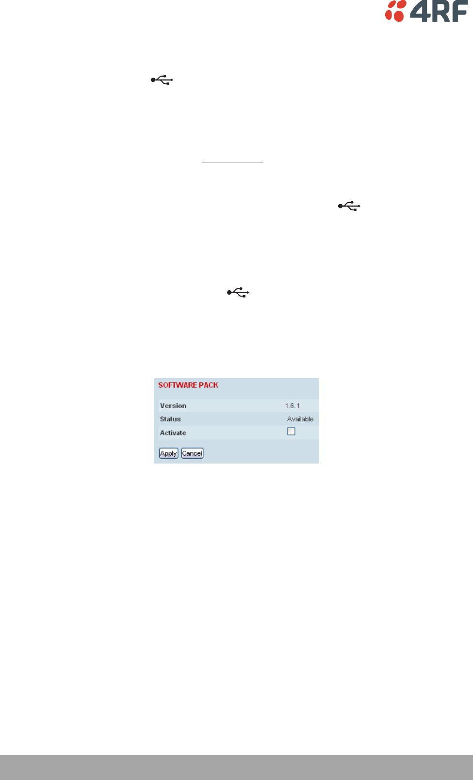
224 | Maintenance
Aprisa SR User Manual
USB Boot Upgrade Method
A single Aprisa SR radio can also be upgraded simply by plugging a USB flash drive containing the new
software into the USB A host port on the Aprisa SR front panel and power cycling the radio.
Upgrade Process
To upgrade the Aprisa SR radio software:
1. Unzip the software release files in to the root directory of a USB flash drive.
2. Check that the SuperVisor USB Boot Upgrade setting is set to ‘Load and Activate’ (see ‘Software >
Setup’ on page 155).
3. Power off the Aprisa SR and insert the USB flash drive into the Host Port .
4. Power on the Aprisa SR.
5. The software upgrade process is complete when the OK LED lights solid orange. This can take about 2
minutes.
The software will have loaded in to the radio Software Pack location.
6. Remove the USB flash drive from the Host Port .
7. Power cycle the Aprisa SR.
Login to the radio being upgraded and go to SuperVisor ‘Software > Manager’ on page 159.
The version of the uploaded software will be displayed in the Software Pack ‘Version’ field.
If the upgrade process did not start, the Aprisa SR could already be operating on the version of software
on the USB flash drive. This will be indicated by flashing OK LED and then the OK, DATA and CPU will light
steady green.

Maintenance | 225
Aprisa SR User Manual
If the radio is not operating on the new software (after the power cycle), it could be caused by the
SuperVisor ‘USB Boot Upgrade’ setting set to ‘Load Only’ (see ‘Software > Setup’ on page 155).
In this case, go to SuperVisor see ‘Software > Manager’ on page 159 and tick the Software Pack ‘Activate’
checkbox and click ‘Appy’.
If any Display Panel LED flashes red or is steady red during the upgrade process, it indicates that the
upgrade has failed. This could be caused by incorrect files on the USB flash drive or a radio hardware
failure.
Software Downgrade
Radio software can also be downgraded if required. This may be required if a new radio is purchased for
an existing network which is operating on an earlier software release.
The downgrade process is the same as the upgrade process.
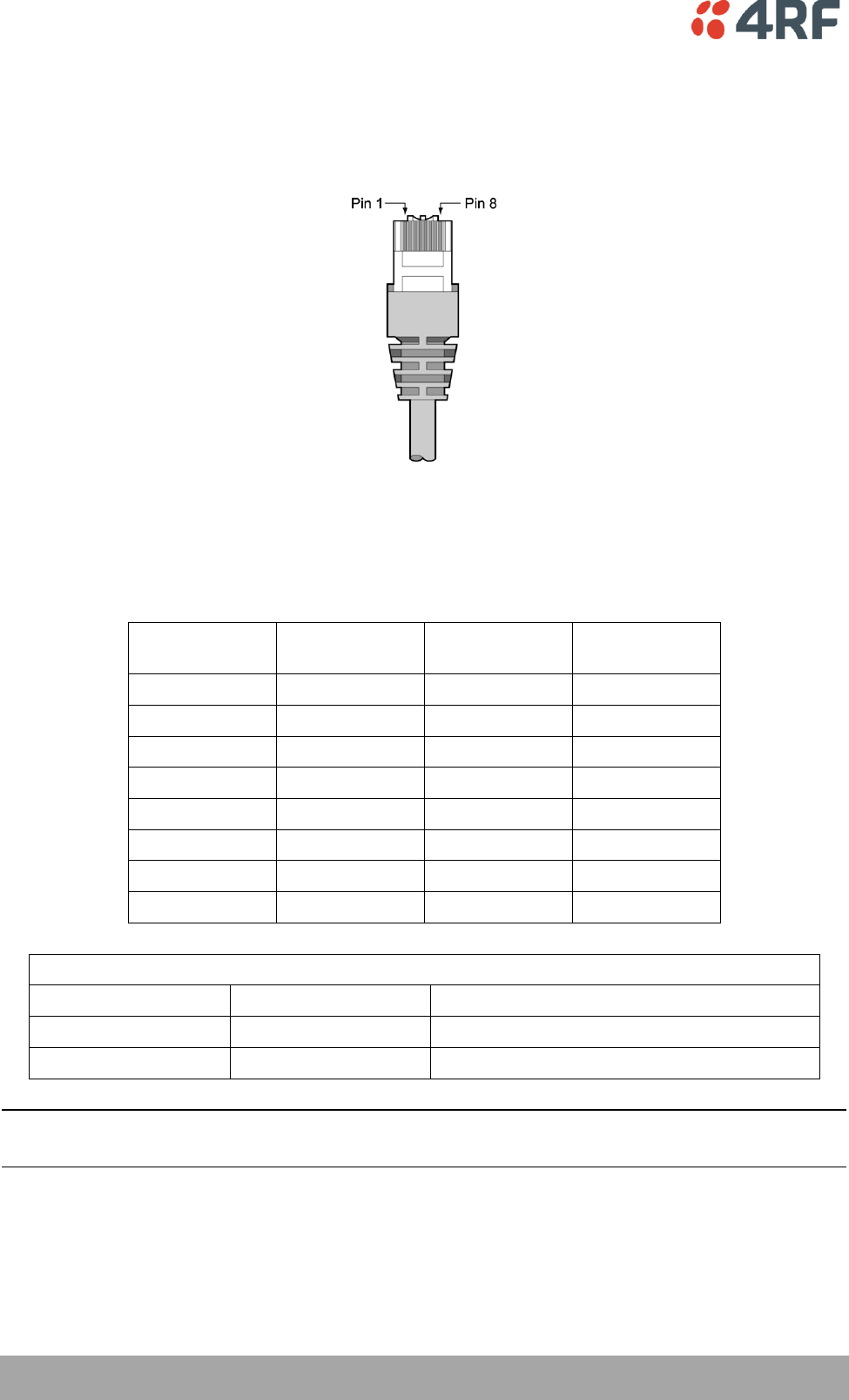
226 | Interface Connections
Aprisa SR User Manual
10. Interface Connections
RJ45 Connector Pin Assignments
RJ45 pin numbering
Ethernet Interface Connections
Pin Number
Pin Function
Direction
TIA-568A wire
colour
1
Transmit
Output
Green/white
2
Transmit
Output
Green
3
Receive
Input
Orange/white
4
Not used
Blue
5
Not used
Blue/white
6
Receive
Input
Orange
7
Not used
Brown/white
8
Not used
Brown
RJ45 connector LED indicators
LED
Status
Explanation
Green
On
Ethernet signal received
Green
Flashing
Indicates data traffic present on the interface
Note: Do not connect Power over Ethernet (PoE) connections to the Aprisa SR Ethernet ports as this will
damage the port.
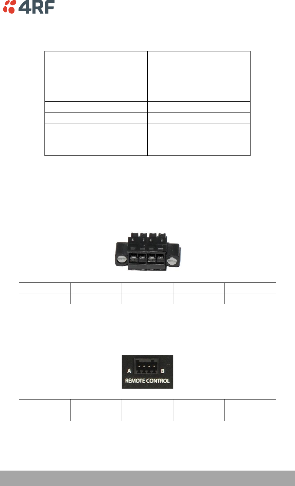
Interface Connections | 227
Aprisa SR User Manual
RS-232 Serial Interface Connections
The RS-232 Serial Interface is always configured as a DCE:
RJ45
Pin Number
Pin Function
Direction
TIA-568A Wire
Colour
1
RTS
Input
Green / white
2
DTR
Input
Green
3
TXD
Input
Orange / white
4
Ground
Blue
5
DCD
Output
Blue / white
6
RXD
Output
Orange
7
DSR
Output
Brown / white
8
CTS
Output
Brown
Hardware Alarms Connections
The power and alarm connector provides two hardware alarm inputs for alarm transmission to the other
radios in the network.
1 2 3 4
Pin Number
1
2
3
4
Function
Alarm Port 1
Alarm Port 2
Power Negative
Power Positive
Protection Switch Remote Control Connections
1 2 3 4
Pin Number
1
2
3
4
Function
A radio active
Ground
B radio active
Ground
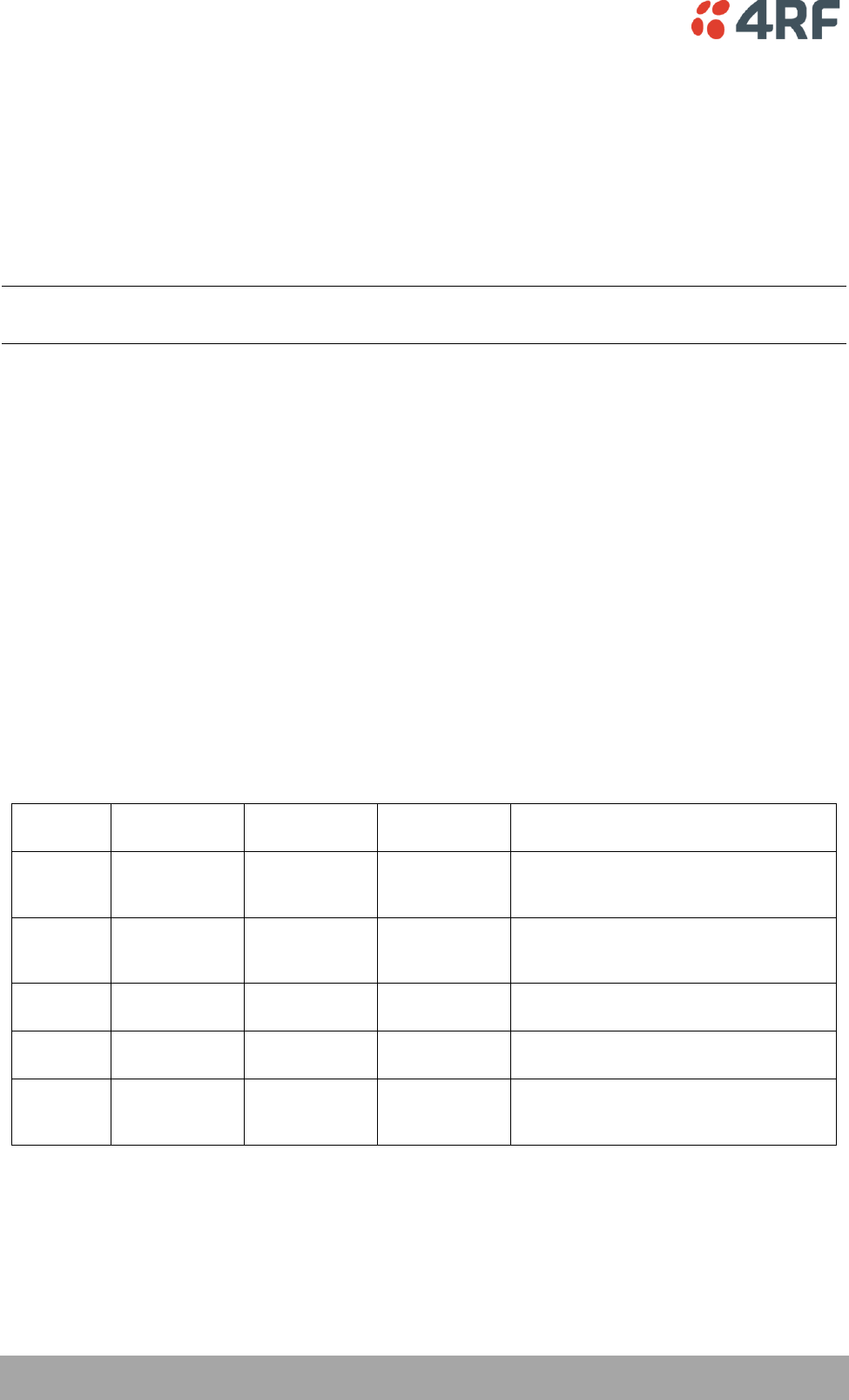
228 | Alarm Types and Sources
Aprisa SR User Manual
11. Alarm Types and Sources
Alarm Types
There are three types of alarm event configuration types:
1. Threshold Type
These alarm events have lower and upper limits. An alarm is raised if current reading is outside the limits.
Note: the limits for PA Current, TX AGC, TX Reverse Power and Thermal shutdown are not user
configurable.
2. Error Ratio Type
This is the ratio of bad packets vs total packets in the defined sample duration.
For Serial, it is the ratio of bad characters vs total characters in the duration seconds. An alarm is raised if
current error ratio is greater than the configured ratio. The error ratio is configured in ‘Upper Limit’ field
and accepts value between 0 and 1. Monitoring of these events can be disabled by setting the duration
parameter to 0.
3. Sample Duration Type
Used for No Receive data events type. An alarm is raised if no data is received in the defined sample
duration. Monitoring of these events can be disabled by setting the duration parameter to 0.
See ‘Events > Events Setup’ on page 146 for setup of alarm thresholds / sample durations etc.
Alarm Events
Transmitter Alarms
Event ID
Event Display
Text
Default
Severity
Configuration
Type
Function
1
PA Current
critical(1)
Threshold Type
Alarm to indicate that the current drawn
by the transmitter power amplifier is
outside defined limits.
2
TX AGC
critical(1)
Threshold Type
Alarm to indicate that the variable gain
control of the transmitter is outside
defined limits.
3
TX Reverse
Power
warning(4)
Threshold Type
Alarm to indicate that the antenna is not
connected to the radio
4
Temperature
Threshold
warning(4)
Threshold Type
Alarm to indicate that the transmitter
temperature is outside defined limits.
31
Thermal
Shutdown
critical(1)
Threshold Type
Alarm to indicate that the transmitter has
shutdown due to excessively high
temperature.

Alarm Types and Sources | 229
Aprisa SR User Manual
Receiver Alarms
Event ID
Event Display
Text
Default
Severity
Configuration
Type
Function
7
RSSI Threshold
warning(4)
Threshold Type
Alarm to indicate that the receiver RSSI
reading taken on the last packet received
is outside defined limits.
8
RX Synthesizer
Not Locked
critical(1)
Not
Configurable
Alarm to indicate that the receiver
Synthesizer is not locked on the RF
received signal.
9
RX CRC Errors
warning(4)
Error Ratio
Type
Alarm to indicate that the data received
on the RF path contains errors at a higher
rate than the defined error rate threshold.
Radio Interface Path Alarms
Event ID
Event Display
Text
Default
Severity
Configuration
Type
Function
34
RF No Receive
Data
warning(4)
Sample
Duration Type
Alarm to indicate that there is no data
received on the RF path in the defined
duration period.
Customer Equipment Interface Path Alarms
Event ID
Event Display
Text
Default
Severity
Configuration
Type
Function
10
Port 1 Eth No
Receive Data
warning(4)
Sample
Duration Type
Alarm to indicate that Ethernet port 1 has
no received input signal in the defined
duration period.
11
Port 1 Eth Data
Receive Errors
warning(4)
Error Ratio
Type
Alarm to indicate that Ethernet port 1
received input signal contains errors at a
higher rate than the defined error rate
threshold.
12
Port 1 Eth Data
Transmit Errors
warning(4)
Error Ratio
Type
Alarm to indicate that Ethernet port 1
transmitted output signal contains errors
at a higher rate than the defined error
rate threshold.
35
Port 2 Eth No
Receive Data
warning(4)
Sample
Duration Type
Alarm to indicate that Ethernet port 2 has
no received input signal in the defined
duration period.
36
Port 2 Eth Data
Receive Errors
warning(4)
Error Ratio
Type
Alarm to indicate that Ethernet port 2
received input signal contains errors at a
higher rate than the defined error rate
threshold.
37
Port 2 Eth Data
Transmit Errors
warning(4)
Error Ratio
Type
Alarm to indicate that Ethernet port 2
transmitted output signal contains errors
at a higher rate than the defined error
rate threshold.
13
Serial Data No
Receive Data
warning(4)
Sample
Duration Type
Alarm to indicate that the RS-232 port has
no received input signal in the defined
duration period.
14
Serial Data
Receive Errors
warning(4)
Error Ratio
Type
Alarm to indicate that the RS-232 port
received input signal contains errors at a
higher rate than the defined error rate
threshold.
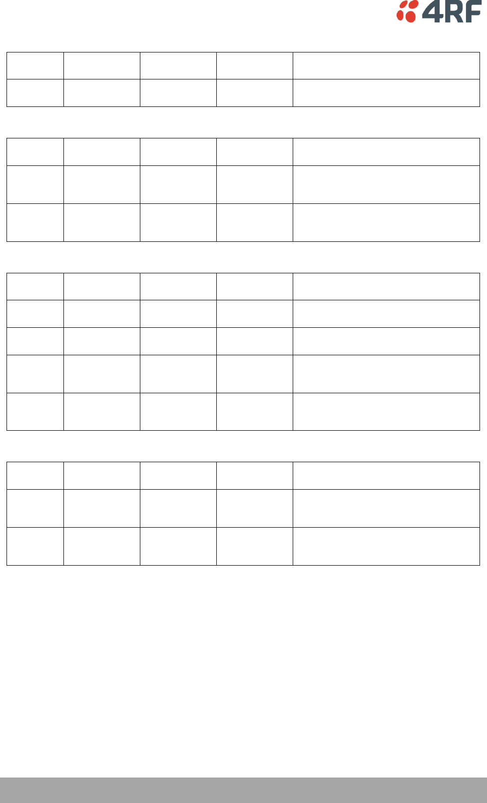
230 | Alarm Types and Sources
Aprisa SR User Manual
Component Failure Alarms
Event ID
Event Display
Text
Default
Severity
Configuration
Type
Function
16
Component
Failure
major(2)
Not
Configurable
Alarm to indicate that a hardware
component has failed.
Diagnostic Alarms
Event ID
Event Display
Text
Default
Severity
Configuration
Type
Function
17
Protection Sw
Manual Lock
warning(4)
Not
Configurable
Alarm to indicate that the Protection
Switch Software Manual Lock has been
activated.
18
Protection Hw
Manual Lock
warning(4)
Not
Configurable
Alarm to indicate that the Protection
Switch Hardware Manual Lock has been
activated.
Software Alarms
Event ID
Event Display
Text
Default
Severity
Configuration
Type
Function
20
Calibration
Failure
major(2)
Not
Configurable
Alarm to indicate that the RF calibration
has failed.
21
Configuration
Not Supported
major(2)
Not
Configurable
Alarm to indicate that a configuration has
entered that is invalid.
32
Network
Configuration
Warning
warning(4)
Not
Configurable
Alarm to indicate a network configuration
problem e.g. duplicate IP address.
39
Software
Restart
Required
warning(4)
Not
Configurable
Alarm to indicate that a configuration has
changed that requires a software reboot.
Protection Alarms
Event ID
Event Display
Text
Default
Severity
Configuration
Type
Function
23
Protection Peer
Comms Lost
major(2)
Not
Configurable
Alarm to indicate that the standby radio
has lost communication with the active
radio.
54
Protection
Hardware
Failure
major(2)
Not
Configurable
Alarm to indicate that there is a failure in
the protection switch hardware.

Alarm Types and Sources | 231
Aprisa SR User Manual
Informational Events
Event ID
Event Display
Text
Default
Severity
Function
26
User
authentication
succeeded
information(5)
Event to indicate that a user is successfully authenticated on
the radio during login. The information on the user that was
successfully authenticated is provided in the eventHistoryInfo
object of the Event History Log.
27
User
authentication
failed
information(5)
Event to indicate that a user has failed to be authenticated
on the radio during login. The information on the user that
was unsuccessfully authenticated is provided in the
eventHistoryInfo object of the Event History Log.
28
Protection
switch failed
information(5)
Event to indicate that a protection switch over cannot occur
for some reason. The reason for the failure to switch is
described in the eventHistoryInfo object of the Event History
Log.
29
Software
System Check
information(5)
Event to indicate that the software has done a system check
on the radio. Any information relevant to the cause of the
event is provided in the eventHistoryInfo object of the Event
History Log.
30
Software Start
Up
information(5)
Event to indicate that the radio software has started. Any
information relevant to the software start up is provided in
the eventHistoryInfo object of the Event History Log.
33
Protection
Switch
Occurred
information(5)
Event to indicate that a protection switch over occurs for
some reason. The reason for the switch over is described in
the eventHistoryInfo object of the Event History Log.
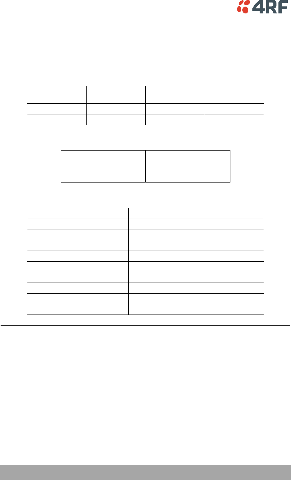
232 | Specifications
Aprisa SR User Manual
12. Specifications
RF Specifications
Frequency Bands
Broadcast Band
Frequency Band
Frequency Tuning
Range
Synthesizer Step
Size
VHF
136 MHz
136-174 MHz
6.250 kHz
UHF
400 MHz
400-470 MHz
6.250 kHz
Channel Sizes
Channel Size
Gross Radio Capacity
12.5 kHz
9.6 kbit/s
25 kHz
19.2 kbit/s
Transmitter
Transmit Power output
0.01 to 5.0 W (+10 to +37 dBm, in 1 dB steps)
Adjacent channel power
< -60 dBc
Transient adjacent channel power
< -50 dBc
Spurious emissions
< -37 dBm
Attack time
< 1.5 ms
Release time
< 1.5 ms
Data turnaround time
< 10 ms
Frequency stability
± 1 ppm
Frequency aging
< 1 ppm / annum
Synthesizer lock time
< 1.5 ms (5 MHz step)
Note: The Aprisa SR transmitter contains power amplifier protection which allows the antenna to be
disconnected from the antenna port without product damage.

Specifications | 233
Aprisa SR User Manual
Receiver
12.5 kHz
25 kHz
Receiver sensitivity
BER < 10-2
–117 dBm
–114 dBm
BER < 10-3
–115 dBm
–112 dBm
BER < 10-6
–113 dBm
–110 dBm
Adjacent channel selectivity
> -47 dBm (> 60 dB)
> -37 dBm (> 65 dB)
Co-channel rejection
> –12 dB
Intermodulation response
rejection
> -37 dBm (> 71 dB)
Blocking or desensitization
> -17 dBm (> 90 dB)
Spurious response rejection
> -32 dBm (> 75 dB)
Receiver spurious radiation
< -57 dBm
Modem
Modulation
4-CPFSK
Forward Error Correction
¾ trellis code
Data Payload Security
Data payload security
CCM* Counter with CBC-MAC
Data encryption
Counter Mode Encryption (CTR) using Advanced
Encryption Standard (AES) 128, 192 or 256 bit
Data authentication
Cipher Block Chaining Message Authentication
Code (CBC-MAC) using Advanced Encryption
Standard (AES) 128, 192 or 256 bit
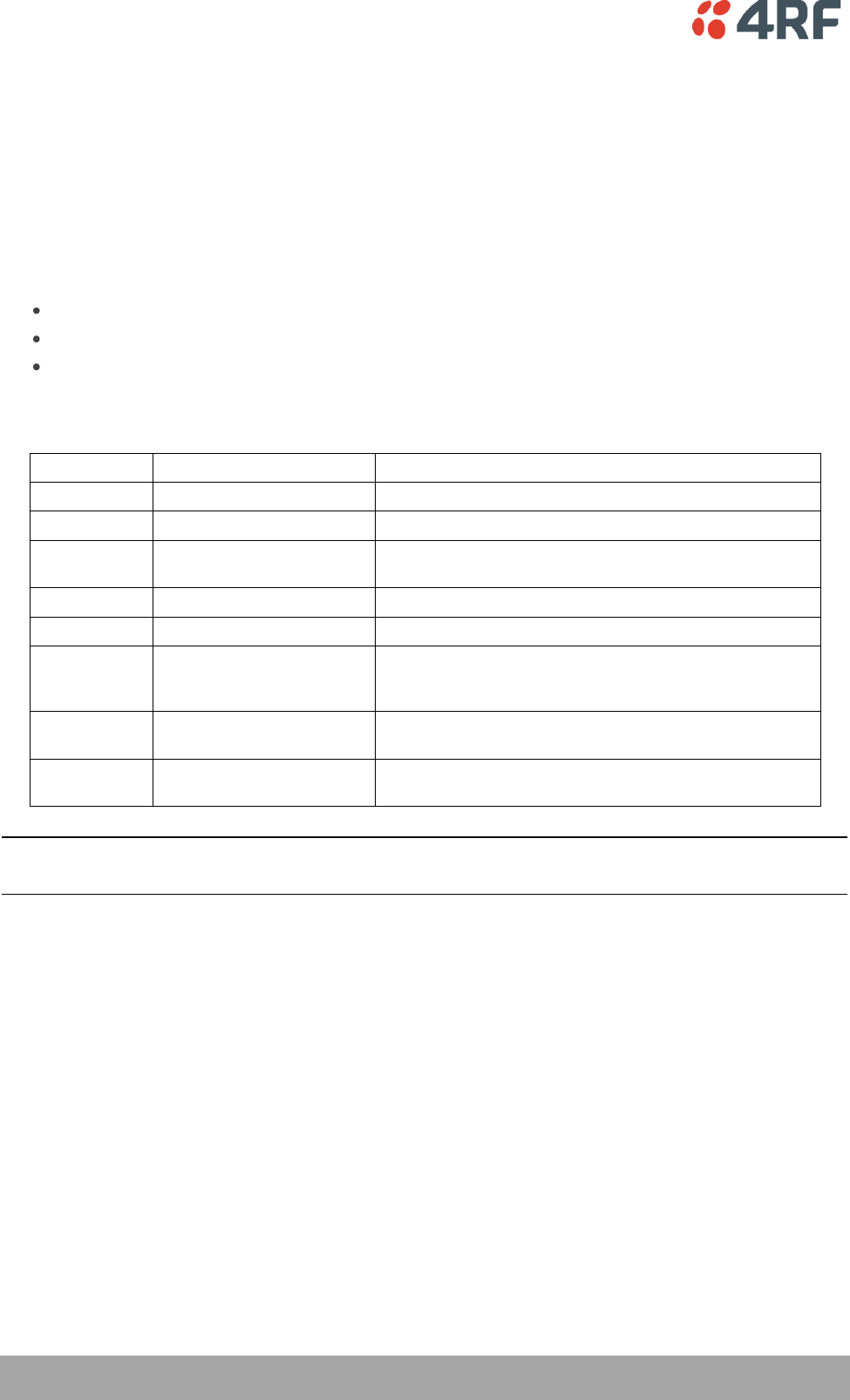
234 | Specifications
Aprisa SR User Manual
Interface Specifications
Ethernet Interface
The Aprisa SR radio features an integrated 10Base-T/100Base-TX layer-2 Ethernet switch.
To simplify network setup, each port supports auto-negotiation and auto-sensing MDI/MDIX. Operators can
select from the following preset modes:
Auto negotiate
10Base-T half or full duplex
100Base-TX half or full duplex
The switch is IEEE 802.3-compatible. It passes VLAN tagged traffic.
General
Interface
RJ45 x 2 (Integrated 2-port switch)
Cabling
CAT-5 UTP, supports auto MDIX (Standard Ethernet)
Maximum line length
100 metres on cat-5 or better
Bandwidth allocation
The Ethernet capacity maximum is determined by the
available radio link capacity.
Maximum transmission unit
Option setting of 1522 or 1536 octets
Address table size
1024 MAC addresses
Ethernet mode
10Base-T or 100Base-TX
Full duplex or half duplex
(Auto-negotiating and auto-sensing)
Diagnostics
Left Green LED
Off: no Ethernet signal received
On: Ethernet signal received
Right Green LED
Off: Indicates no data traffic present on the interface
Flashing: Indicates data traffic present on the interface
Note: Do not connect Power over Ethernet (PoE) connections to the Aprisa SR Ethernet ports as this will
damage the port.
Specifications | 235
Aprisa SR User Manual
RS-232 Asynchronous Interface
The Aprisa SR radio’s ITU-T V.24 compliant RS-232 interface is configured as a Cisco® pinout DCE. The
interface terminates to a DTE using a straight-through cable or to a DCE with a crossover cable (null
modem).
The interface uses two handshaking control lines between the DTE and the DCE.
General
Interface
ITU-T V.24 / EIA/TIA RS-232E
Interface direction
DCE only
Maximum line length
10 metres
Async
parameters
Standard mode data bits
7 or 8 bits
Standard mode parity
Configurable for None, Even or Odd
Standard mode stop bits
1 or 2 bits
Interface baud rates
300, 1200, 2400, 4800, 9600, 19200, 38400, 57600 and
115200 bit/s
Control signals
DCE to DTE
CTS, RTS, DSR, DTR
Hardware Alarms Interface
Alarm Inputs
The power and alarm connector provides two hardware alarm inputs for alarm transmission to the other
radios in the network.
Detector type
Non-isolated ground referenced voltage
detector
Detection voltage - on
> +10 VDC
Detection voltage - off
< +4 VDC
Maximum applied input voltage
30 VDC
Maximum input current limit
10 mA
Protection Switch Specifications
RF Insertion Loss
< 0.5 dB
Remote Control inputs
Logic 4700 ohms pullup to +3.3 VDC
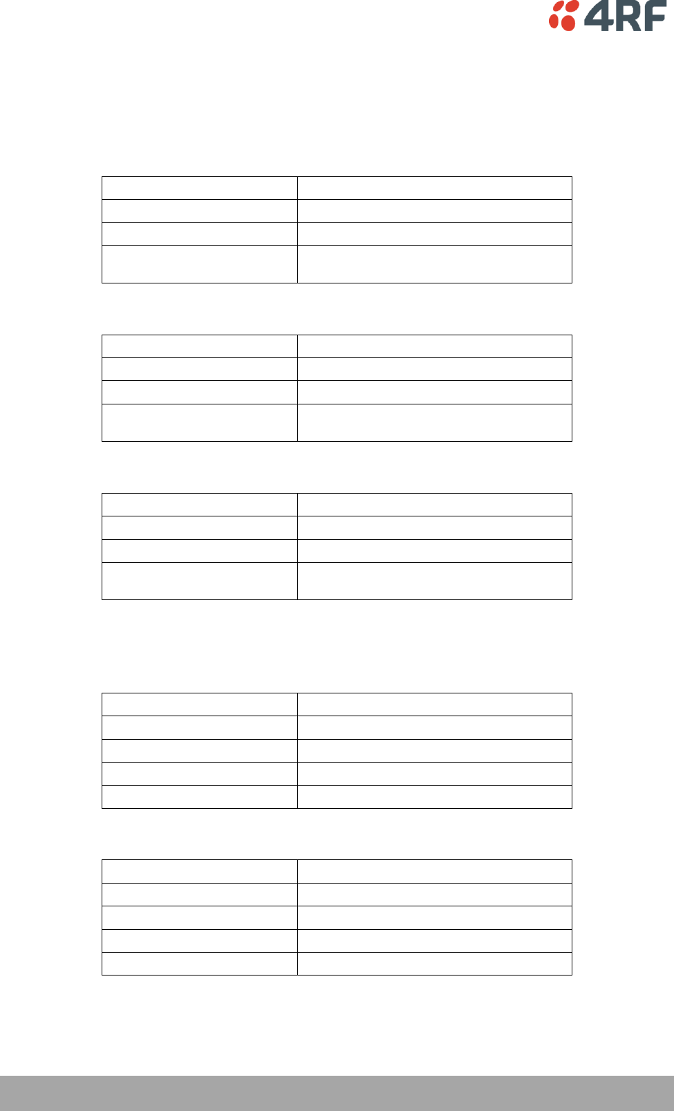
236 | Specifications
Aprisa SR User Manual
Power Specifications
Power Supply
Aprisa SR Radio
Nominal voltage
+13.8 VDC (negative earth)
Absolute input voltage range
+10 to +30 VDC
Maximum power input
30 W
Connector
Phoenix Contact 4 pin male screw fitting
MC 1.5/ 4-GF-3.5
Aprisa SR Protected Station
Nominal voltage
+13.8 VDC (negative earth)
Absolute input voltage range
+10 to +30 VDC
Maximum power input
35 W
Connector
2x Phoenix Contact 2 pin male screw fitting
MC 1.5/ 2-GF-3.5
Aprisa SR Data Driven Protected Station
Nominal voltage
+13.8 VDC (negative earth)
Absolute input voltage range
+10 to +30 VDC
Maximum power input
35 W
Connector
2x Phoenix Contact 4 pin male screw fitting
MC 1.5/ 2-GF-3.5
Power Consumption
Aprisa SR Radio
Mode
Power Consumption
Transmit / Receive
< 22.5 W for 5W transmit power
< 15.0 W for 1W transmit power
Receive only
< 6 W full Ethernet traffic activity
< 4.5 W no Ethernet traffic activity
Aprisa SR Protected Station and Aprisa SR Data Driven Protected Station
Mode
Power Consumption
Transmit / Receive
< 31 W for 5W transmit power
< 23.5 W for 1W transmit power
Receive only
< 14.5 W full Ethernet traffic activity
< 11.5 W no Ethernet traffic activity

Specifications | 237
Aprisa SR User Manual
Power Dissipation
Aprisa SR Radio
Transmit Power
Power Dissipation
1W transmit power
< 14.0 W
5W transmit power
< 17.5 W
Aprisa SR Protected Station and Aprisa SR Data Driven Protected Station
Transmit Power
Power Dissipation
1W transmit power
< 22.5 W
5W transmit power
< 26.0 W
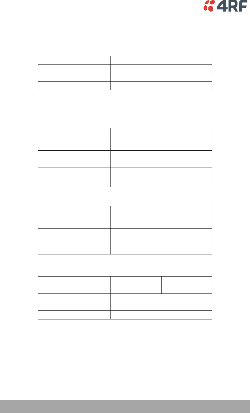
238 | Specifications
Aprisa SR User Manual
General Specifications
Environmental
Operating temperature range
- 40 to + 70˚ C
Storage temperature range
- 40 to + 80˚ C
Operating humidity
Maximum 95% non-condensing
Acoustic noise emission
No audible noise emission
Mechanical
Aprisa SR Radio
Dimensions
Width 177 mm
Depth 110 mm (126 mm with TNC connector)
Height 41.5 mm
Weight
720 g
Colour
Matt black
Mounting
Wall (2 x M5 screws)
Rack shelf (2 x M4 screws)
DIN rail bracket
Aprisa SR Protected Station
Dimensions
Width 430 mm
Depth 220 mm (incl interconnect cables)
Height 90 mm
Weight
4.46 kg
Colour
Matt black
Mounting
Rack mount (2 x M4 screws)
Compliance
12.5 kHz
25 kHz
Radio
EN 300 113-2
EN 302 561
EMI / EMC
EN 301 489 Parts 1 & 5
Safety
EN 60950
Environmental
ETS 300 019 Class 3.4

Product End Of Life | 239
Aprisa SR User Manual
13. Product End Of Life
End-of-Life Recycling Programme (WEEE)
The WEEE Directive concerns the recovery, reuse, and recycling of electronic and electrical equipment.
Under the Directive, used equipment must be marked, collected separately, and disposed of properly.
4RF has implemented an end-of-life recycling programme to manage the reuse, recycling, and recovery of
waste in an environmentally safe manner using processes that comply with the WEEE Directive (EU Waste
Electrical and Electronic Equipment 2002/96/EC).
The WEEE Symbol Explained
This symbol appears on Electrical and Electronic Equipment (EEE) as part of the WEEE (Waste EEE)
directive. It means that the EEE may contain hazardous substances and must not be thrown away with
municipal or other waste.
WEEE Must Be Collected Separately
You must not dispose of electrical and electronic waste with municipal and other waste. You must
separate it from other waste and recycling so that it can be easily collected by the proper regional WEEE
collection system in your area.
YOUR ROLE in the Recovery of WEEE
By separately collecting and properly disposing of WEEE, you are helping to reduce the amount of WEEE
that enters the waste stream.
One of the aims of the WEEE directive is to divert EEE away from landfill and encourage recycling.
Recycling EEE means that valuable resources such as metals and other materials (which require energy to
source and manufacture) are not wasted. Also, the pollution associated with accessing new materials and
manufacturing new products is reduced.
EEE Waste Impacts the Environment and Health
Electrical and electronic equipment (EEE) contains hazardous substances which have potential effects on
the environment and human health. If you want environmental information on the Aprisa SR radio, contact
us (on page 15).

Abbreviations | 241
Aprisa SR User Manual
14. Abbreviations
AES Advanced Encryption Standard
AGC Automatic Gain Control
BER Bit Error Rate
CBC Cipher Block Chaining
CCM Counter with CBC-MAC integrity
DCE Data Communications Equipment
DTE Data Radio Equipment
EMC Electro-Magnetic Compatibility
EMI Electro-Magnetic Interference
ESD Electro-Static Discharge
ETSI European Telecommunications Standards
Institute
FW Firmware
HW Hardware
IF Intermediate Frequency
IP Internet Protocol
I/O Input/Output
ISP Internet Service Provider
kbit/s Kilobits per second
kHz Kilohertz
LAN Local Area Network
LED Light Emitting Diode
mA Milliamps
MAC Media Access Control
MAC Message Authentication Code
Mbit/s Megabits per second
MHz Megahertz
MIB Management Information Base
MTBF Mean Time Between Failures
MTTR Mean Time To Repair
ms milliseconds
NMS Network Management System
PC Personal Computer
PCA Printed Circuit Assembly
PLL Phase Locked Loop
ppm Parts Per Million
PMR Public Mobile Radio
RF Radio Frequency
RoHS Restriction of Hazardous Substances
RSSI Received Signal Strength Indication
RX Receiver
SNMP Simple Network Management Protocol
SNR Signal to Noise Ratio
SWR Standing Wave Ratio
TCP/IP Transmission Control Protocol/Internet
Protocol
TCXO Temperature Compensated Crystal Oscillator
TFTP Trivial File Transfer Protocol
TMR Trunk Mobile Radio
TX Transmitter
UTP Unshielded Twisted Pair
VAC Volts AC
VCO Voltage Controlled Oscillator
VDC Volts DC
WEEE Waste Electrical and Electronic Equipment

242 | Index
Aprisa SR User Manual
15. Index
A
access rights 120
accessory kit 14
antennas
aligning 217
installing 57
selection and siting 48
siting 50
attenuators 47
B
bench setup 47
C
cabling
accessory kit 14
coaxial feeder 47, 51
CD contents 14
E
earthing 47, 51, 53
environmental requirements 52
F
feeder cables 51
front panel
connections 24
H
hardware
accessory kit 14
installing 57
humidity 52
I
in-service commissioning 216
interface connections 224
Ethernet 224
RS-232 Serial 225
J
Java
requirement for 14
L
lightning protection 53
linking system plan 51
logging in
SuperVisor 67
logging out
SuperVisor 68
M
maintenance summary 129
mounting kit 14
O
operating temperature 52
P
passwords
changing 121
path planning 48
path propagation calculator 48
pinouts
Ethernet 224
RS-232 Serial 225
power supply 52
R
radio
earthing 47, 53
logging into 67
logging out 68
operating temperature 52
rebooting 134
storage temperature 52
rebooting the radio 134
RS-232
serial data 101
RS-232 Serial interface 100, 101, 106, 182
interface connections for 225

Index | 243
Aprisa SR User Manual
port settings for 101
S
security
settings115, 122, 124, 126, 142, 146, 148, 149
summary 114
security users
user privileges 120
SuperVisor
logging into 67
logging out 68
PC settings for 63
T
temperature 52
tools 54
U
users
adding 120
changing passwords 121
deleting 121
user details 120
user privilege 121
W
WEEE 237