4RF SRN0400025A P-TO-MP FIXED TRANSMITTER, SCADA APPLICATIONS User Manual Aprisa SR Product Description
4RF Limited P-TO-MP FIXED TRANSMITTER, SCADA APPLICATIONS Aprisa SR Product Description
UserManual.wiki
>
4RF
>
SRN0400025A User Manual
User Manual
Navigation menu
Upload a User Manual
Namespaces
Wiki Guide
HTML
PDF
Info
Views
User Manual
Discussion / Help
Navigation
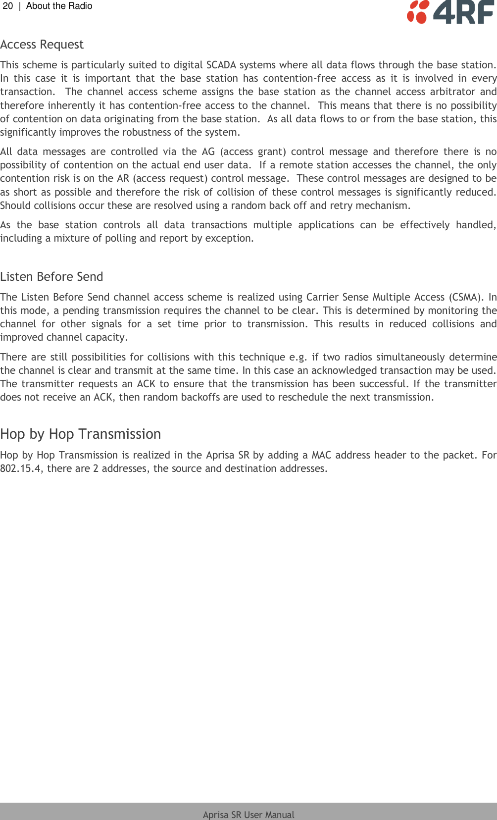
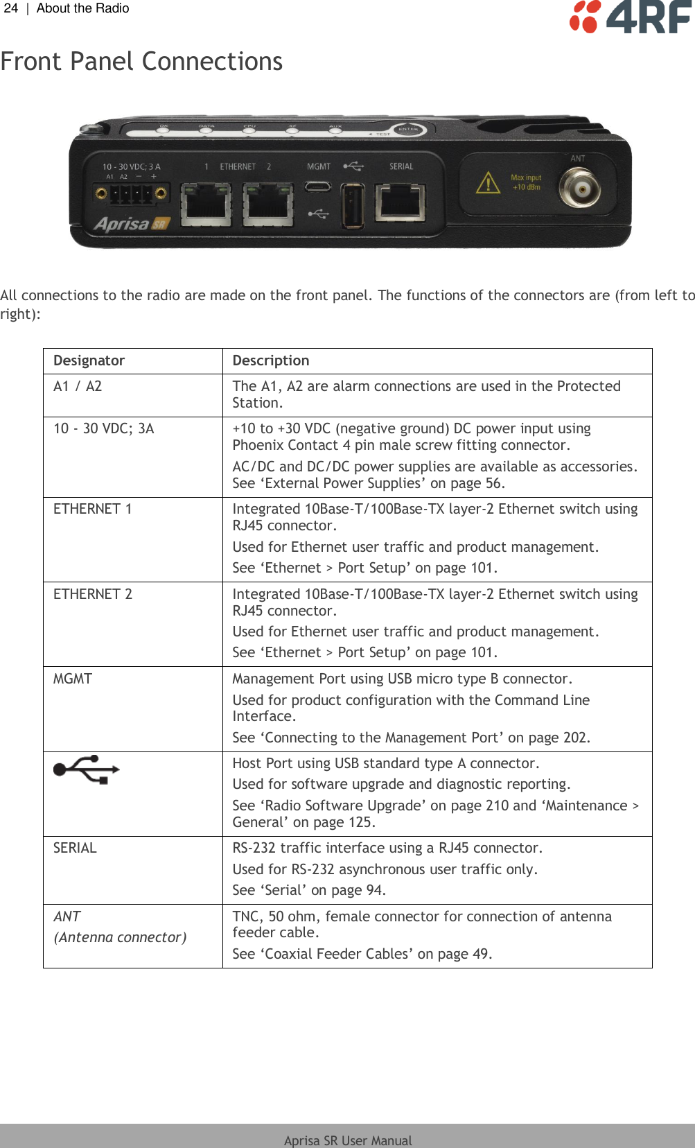
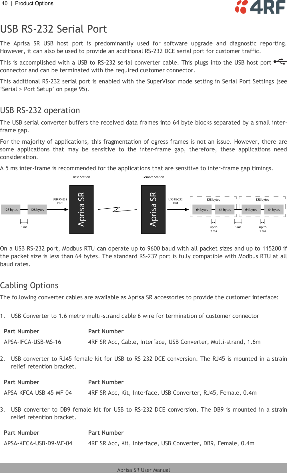
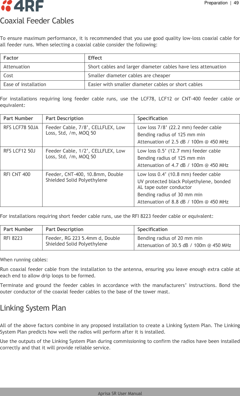
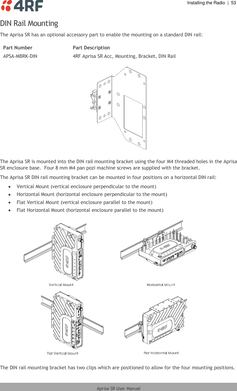

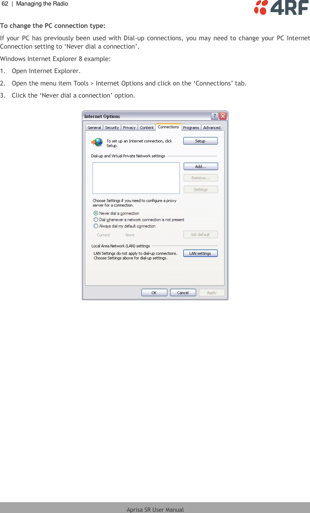
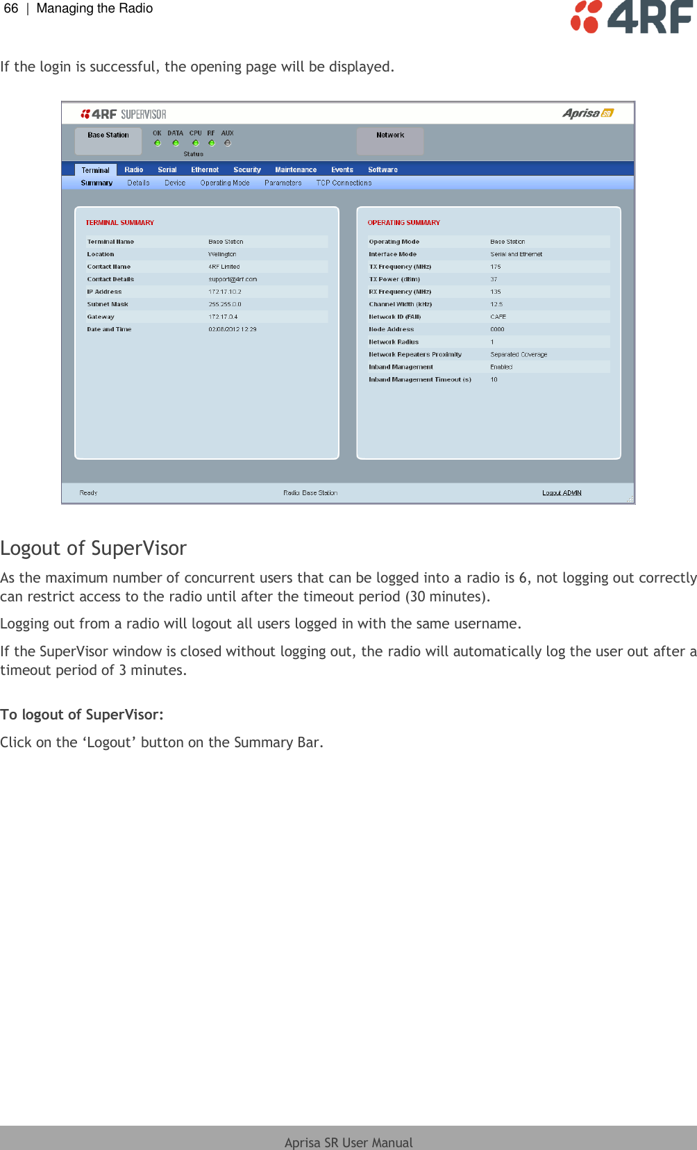
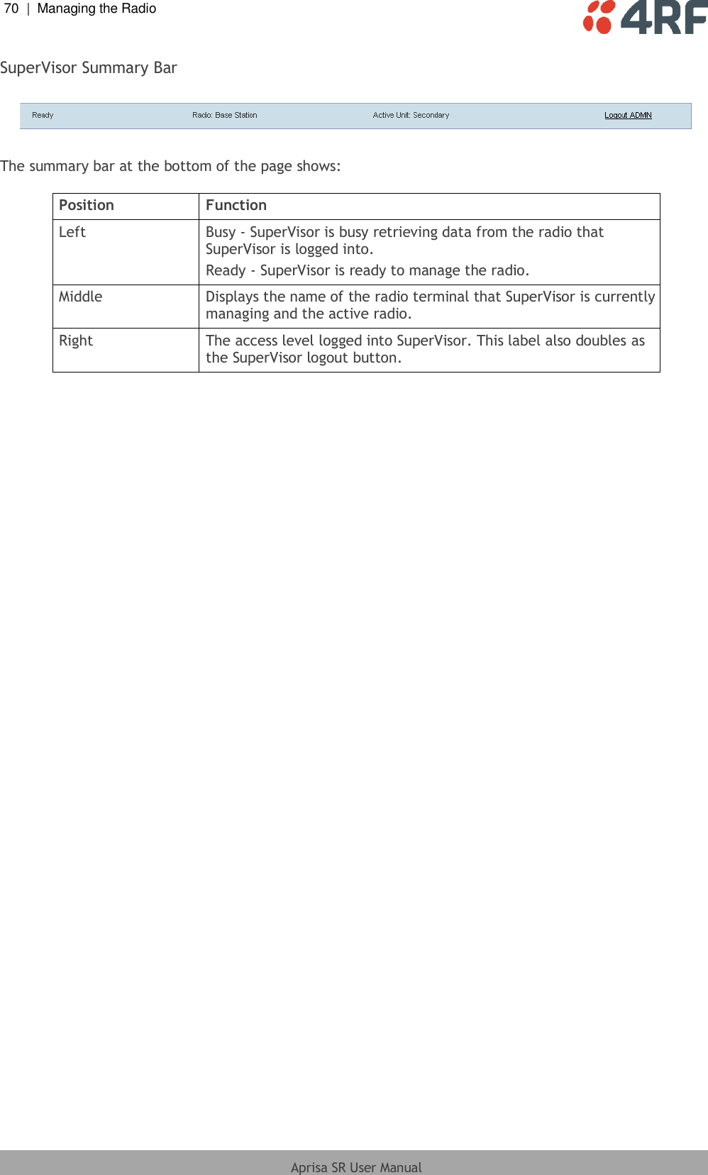
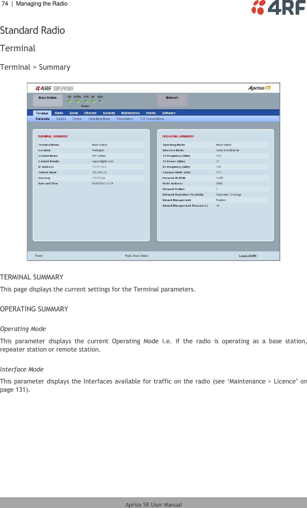
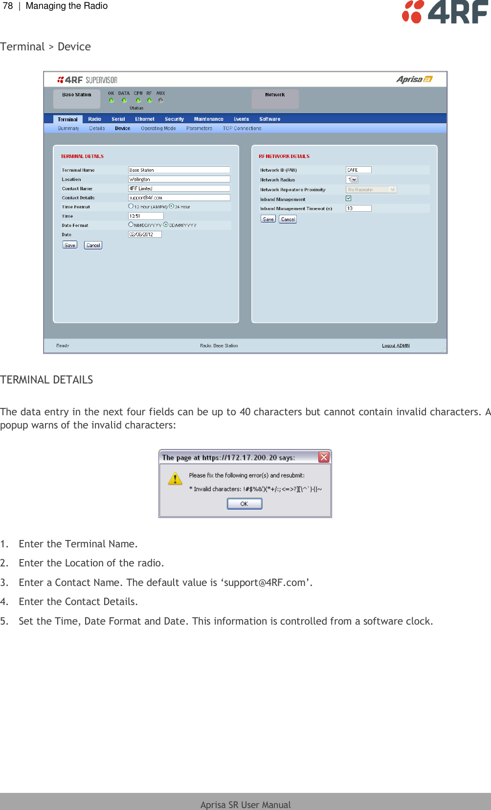
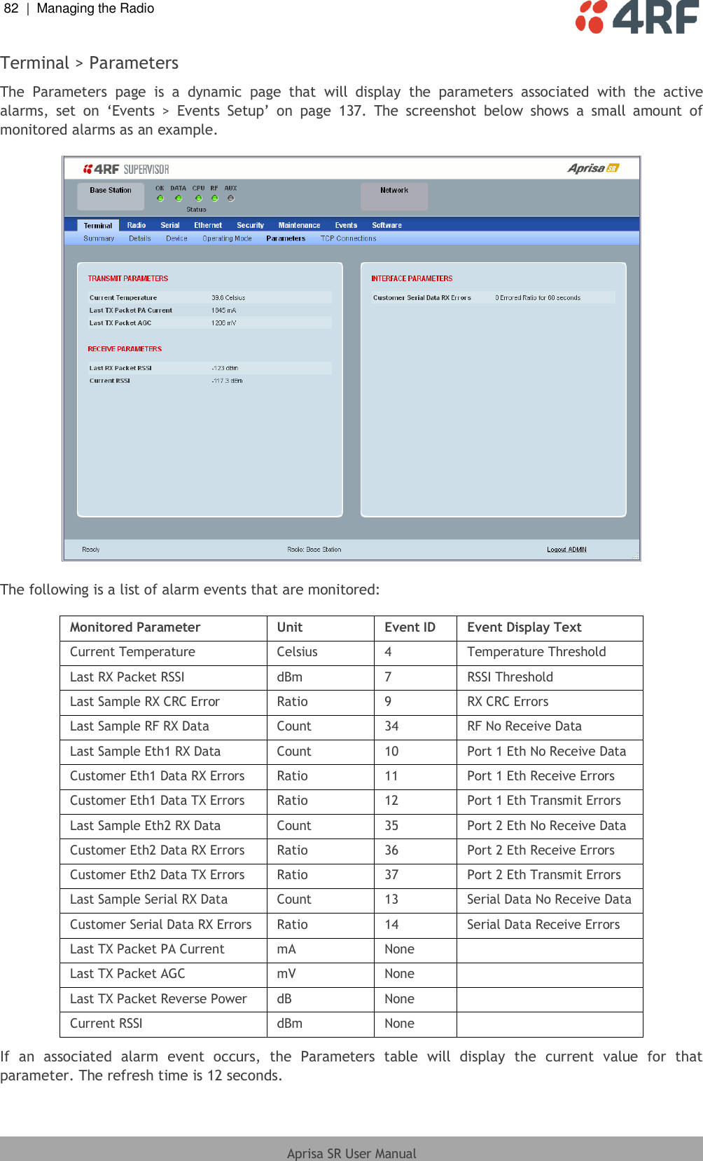
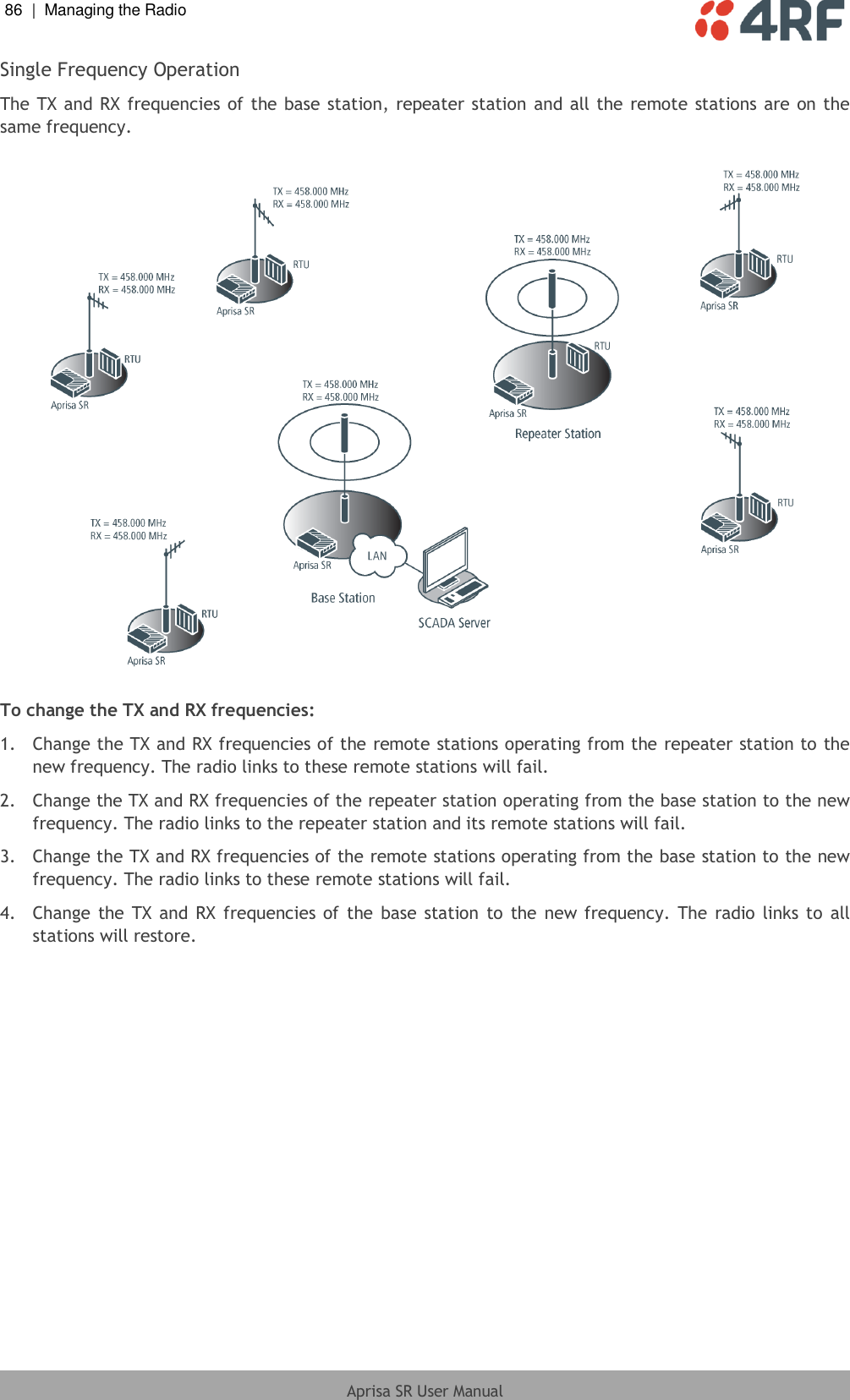
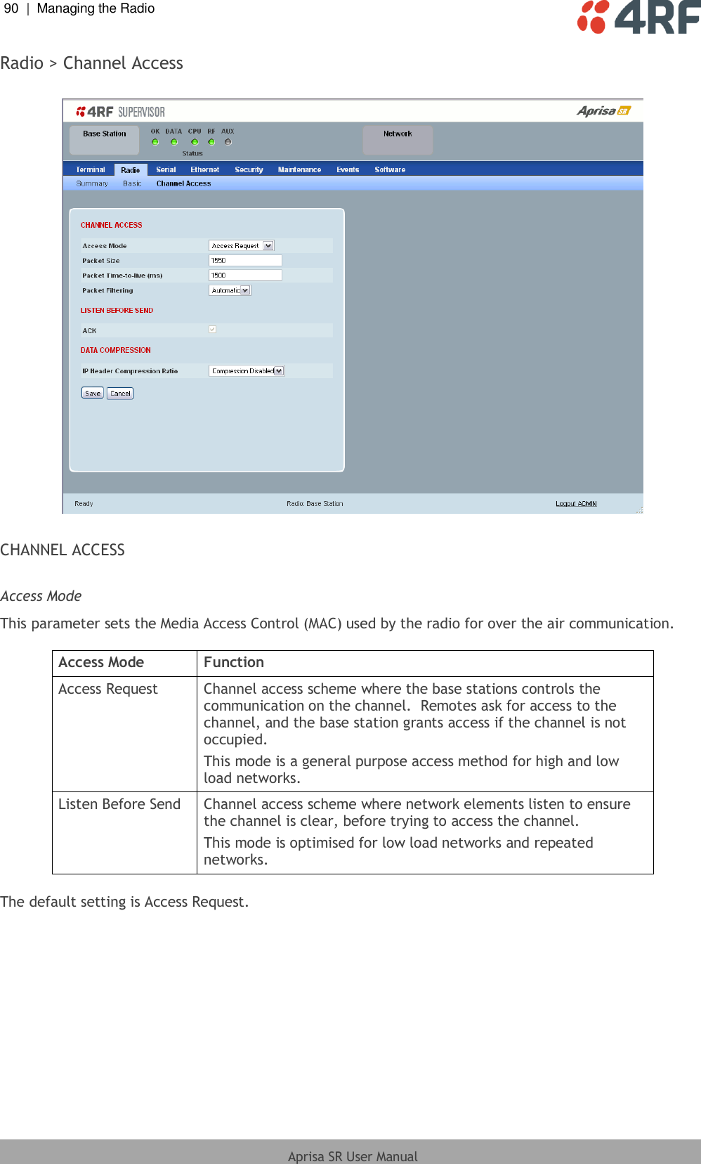
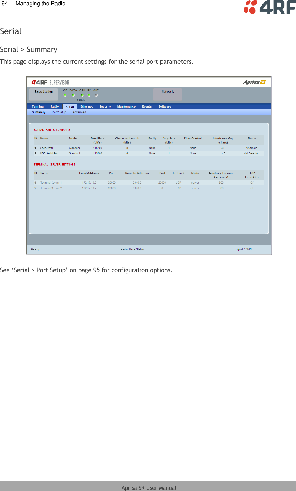
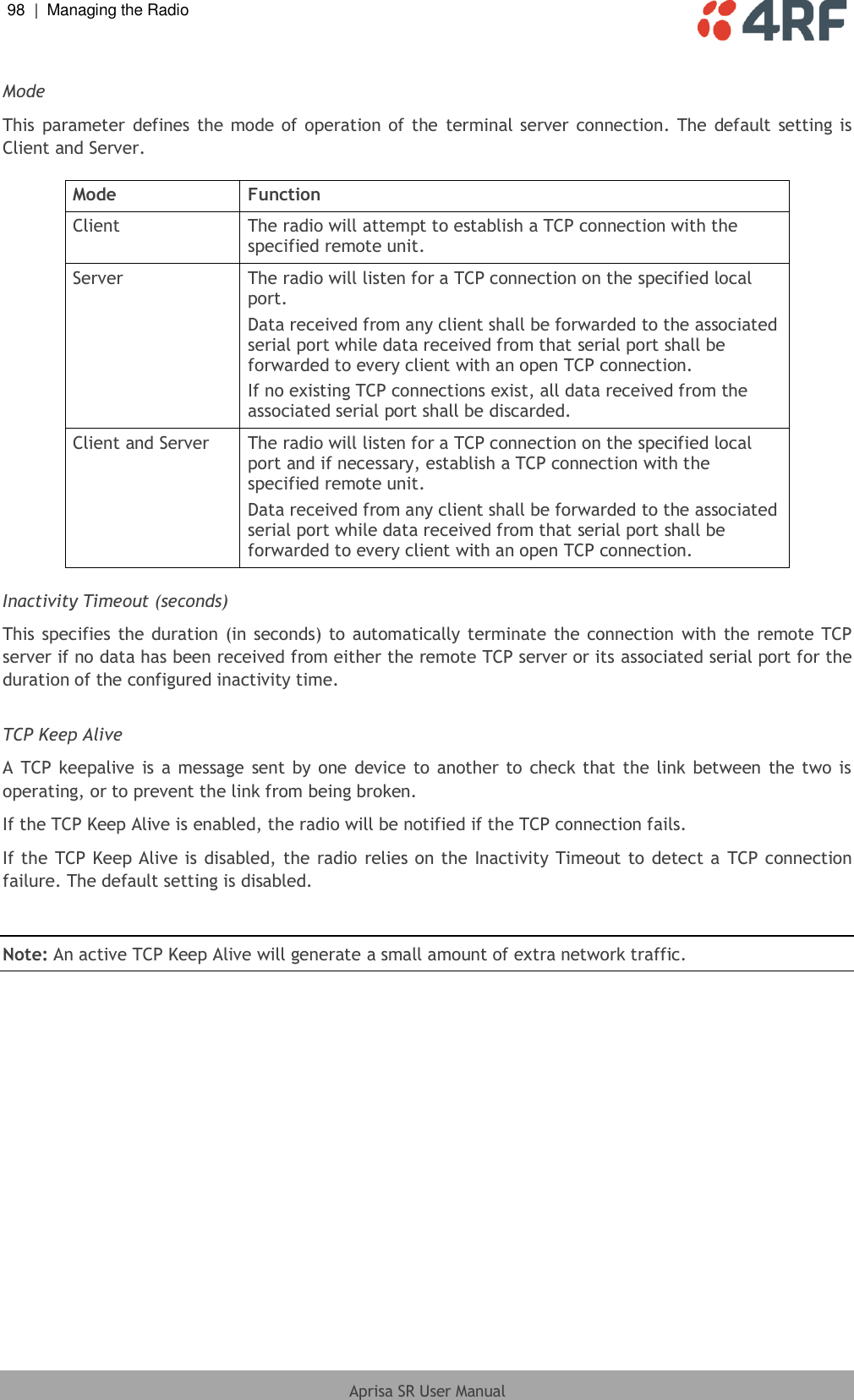
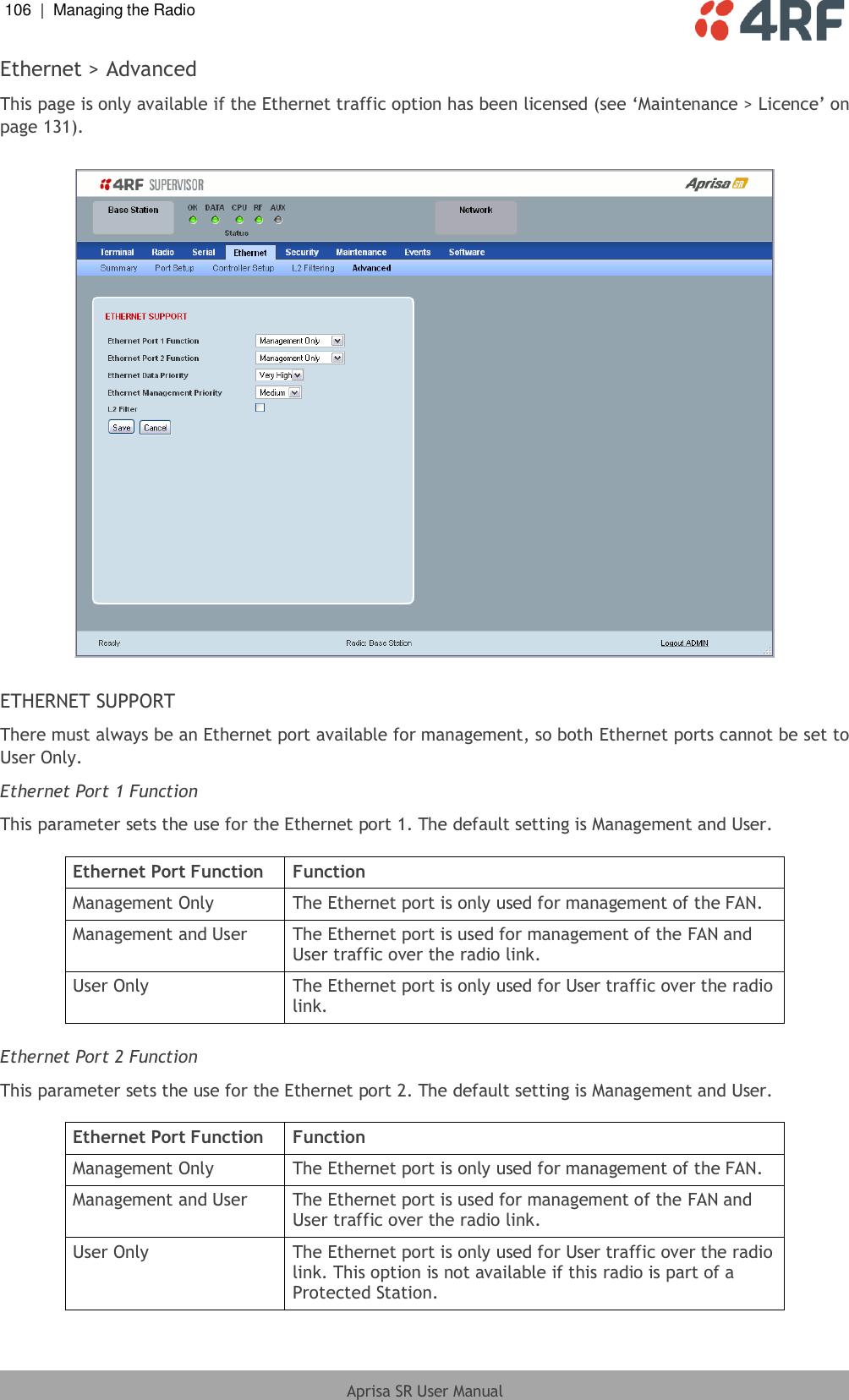
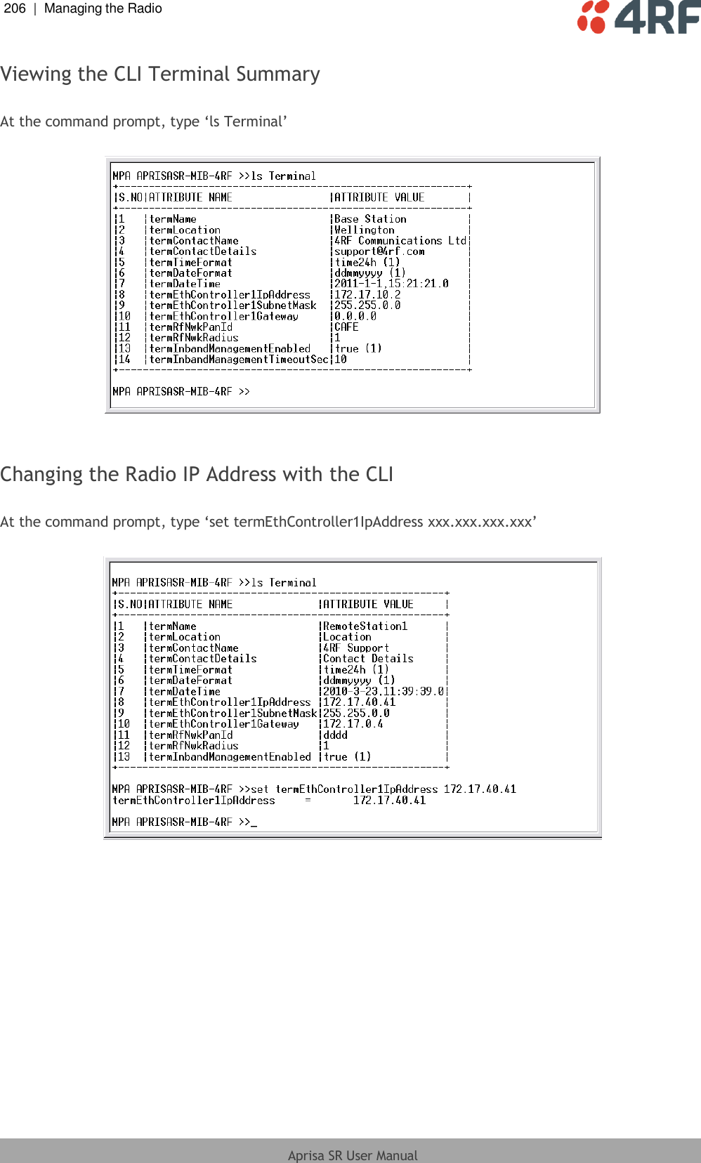
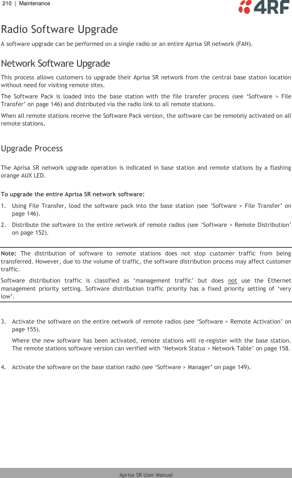
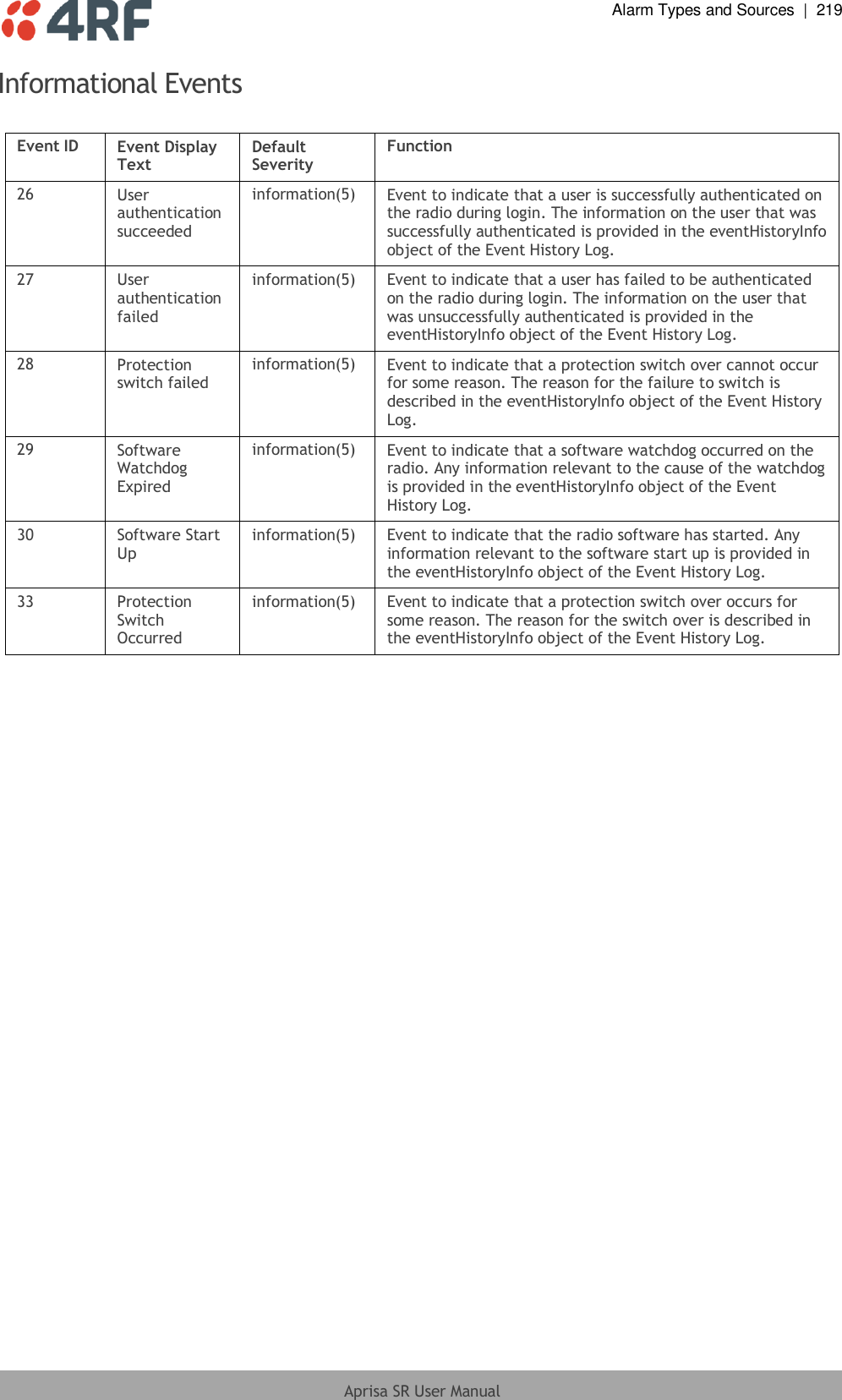
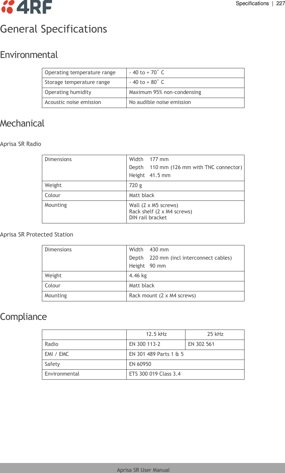
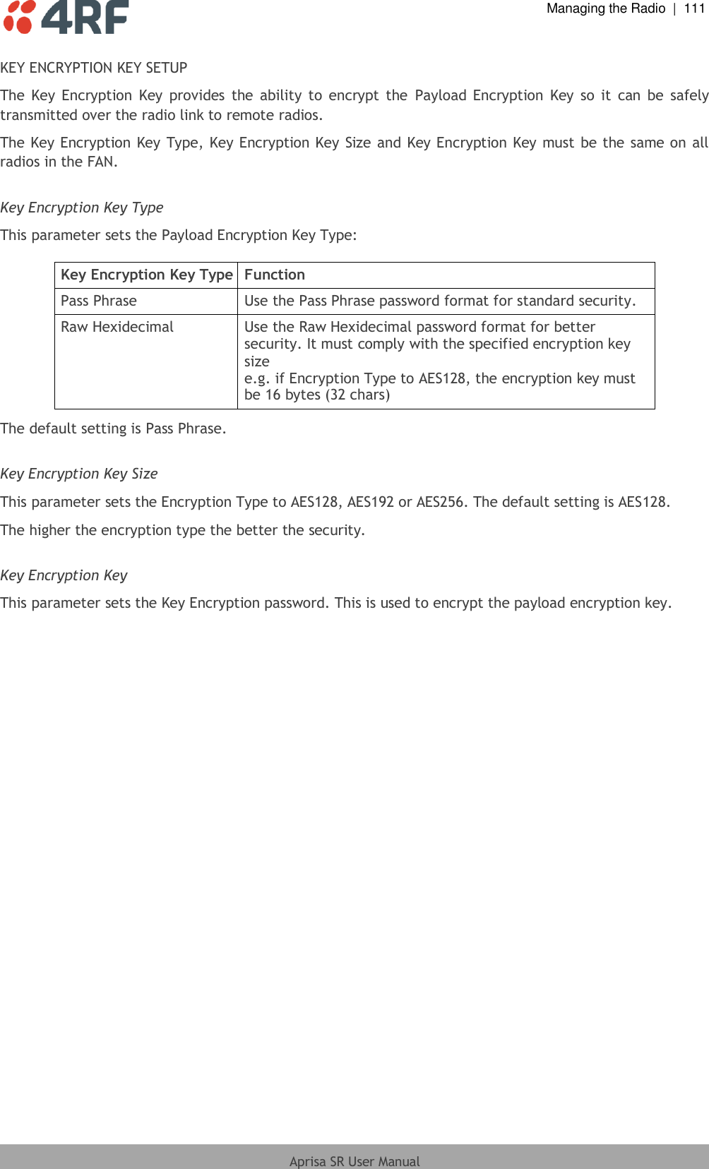
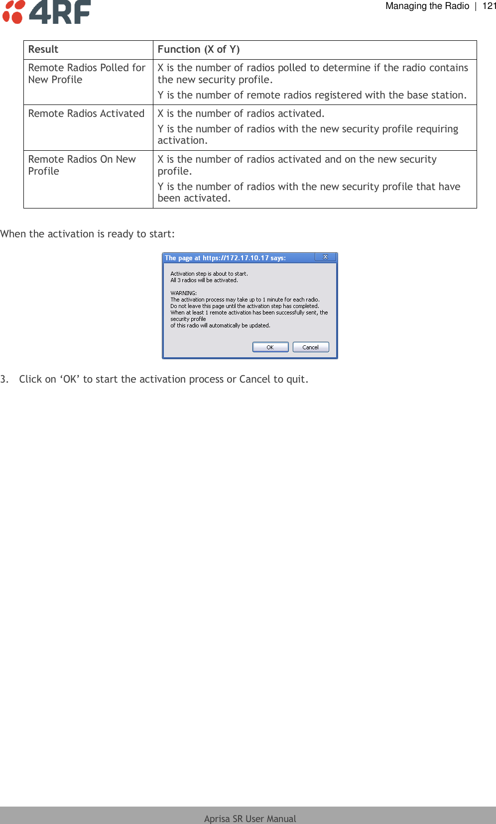
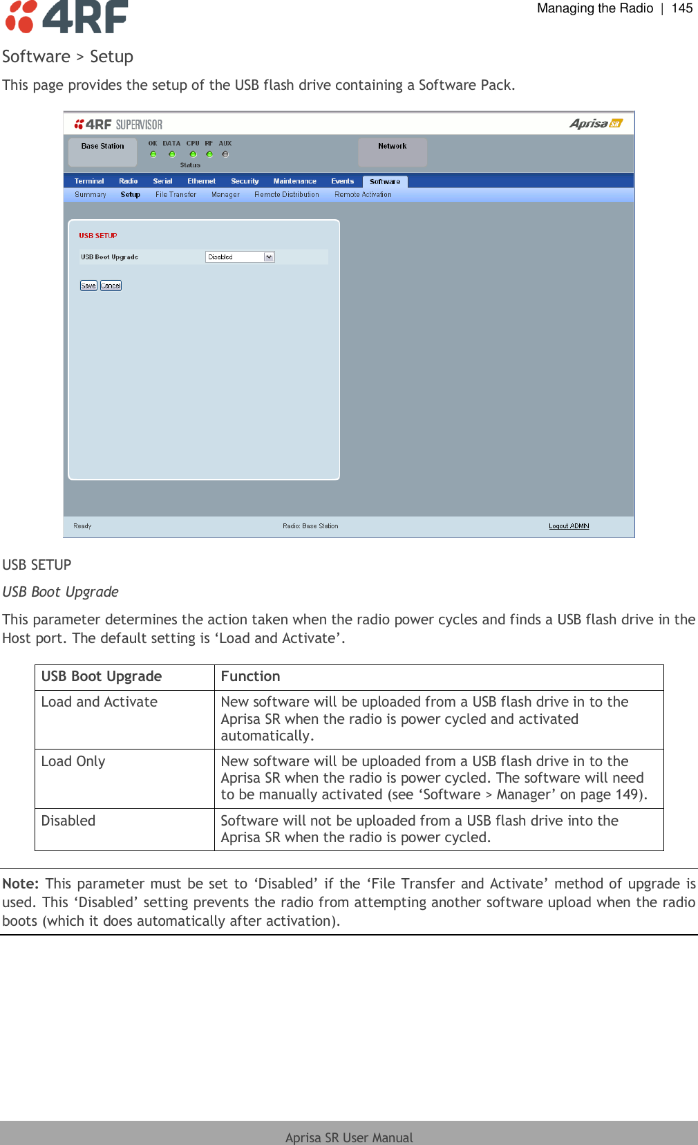
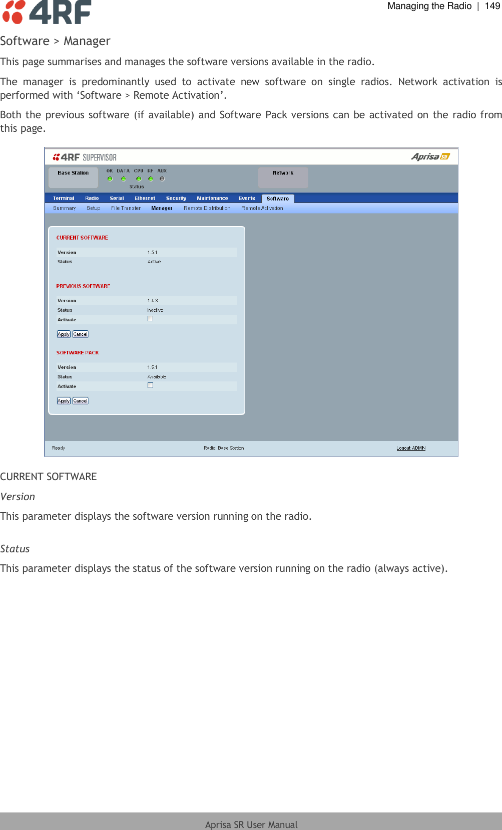
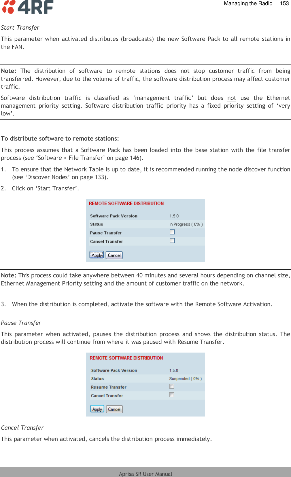
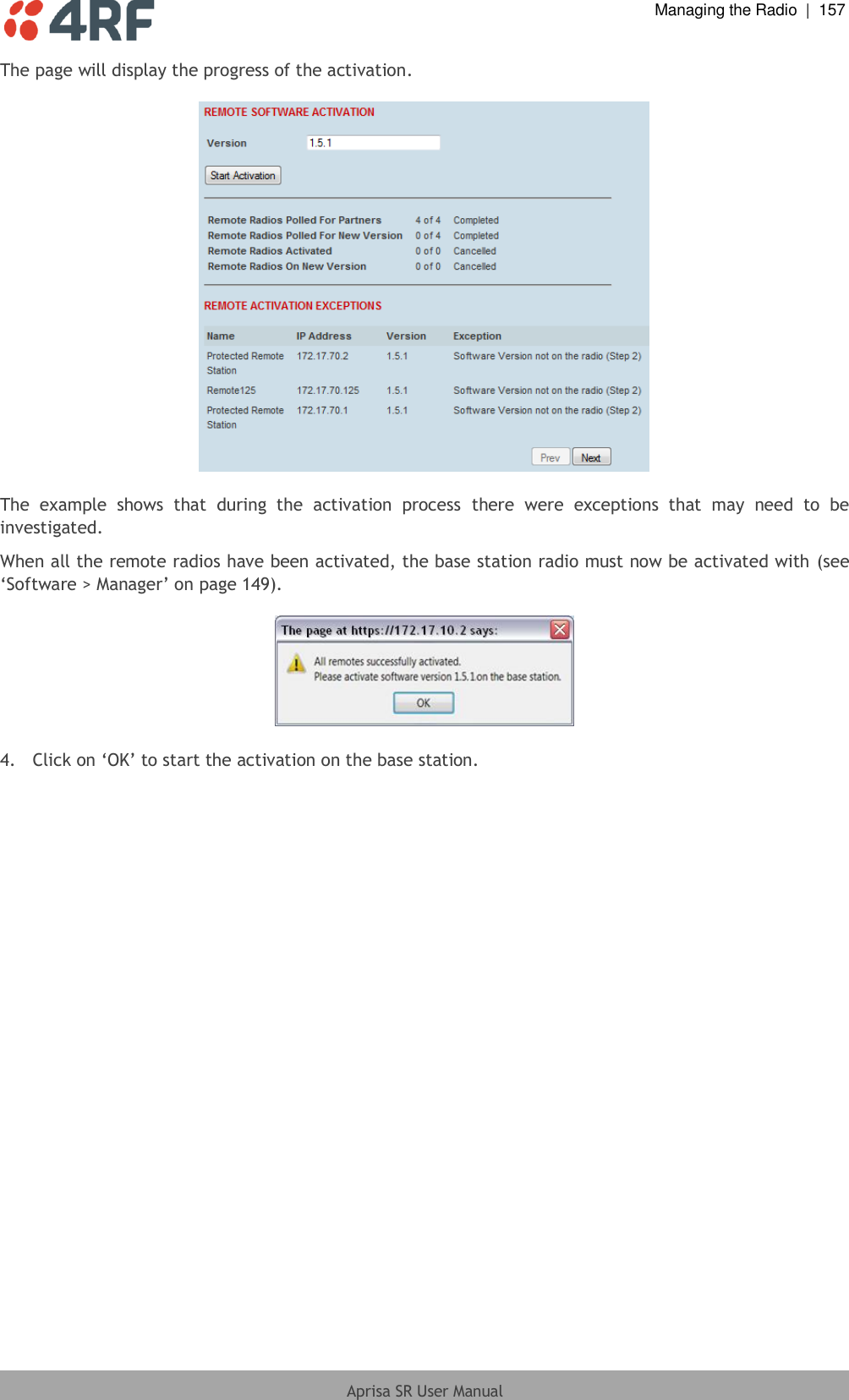
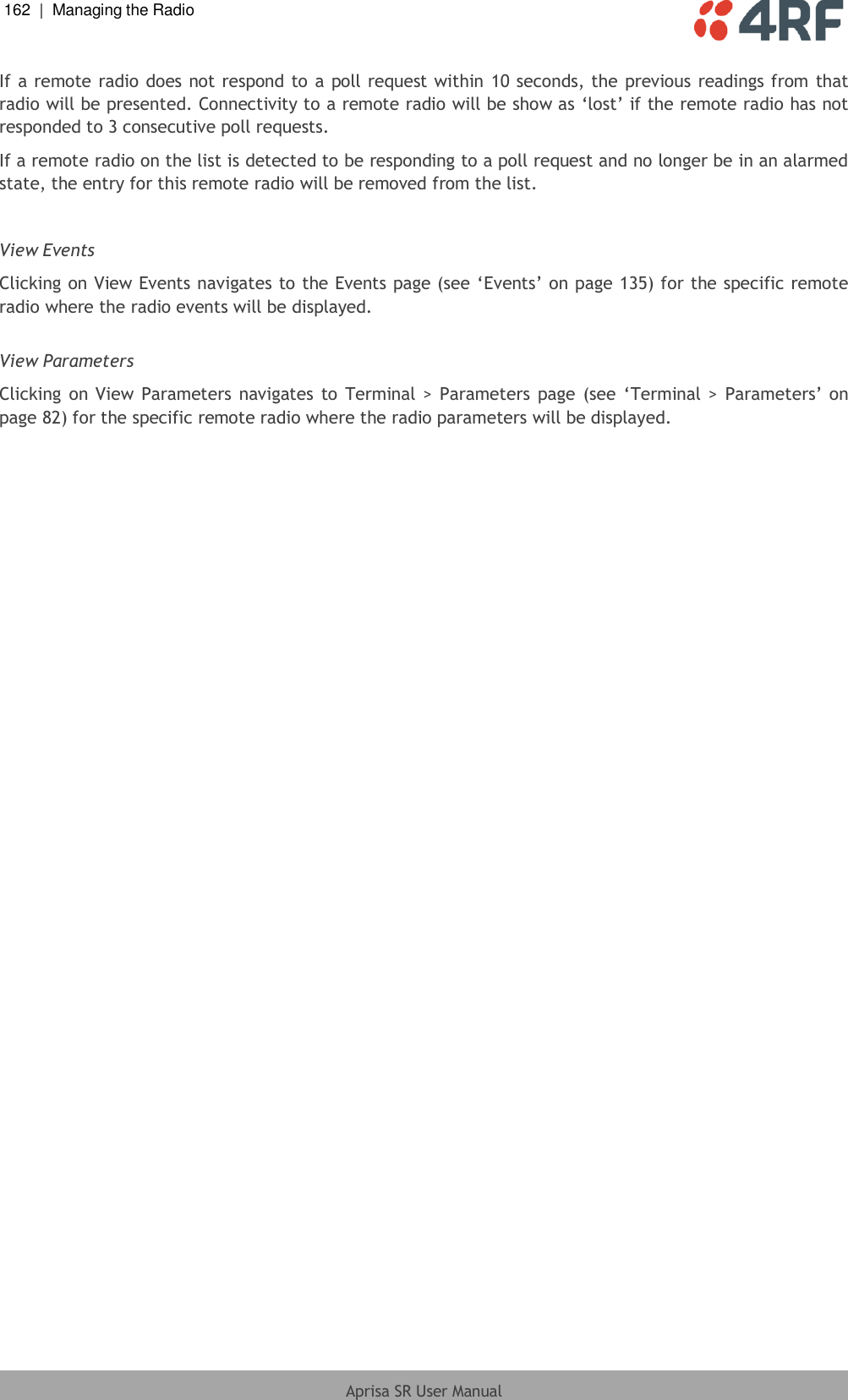
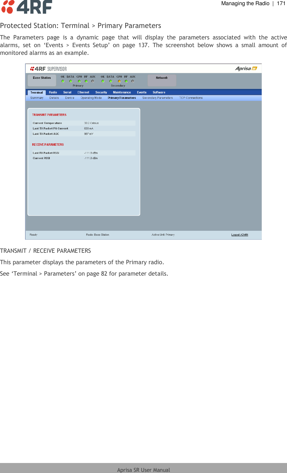
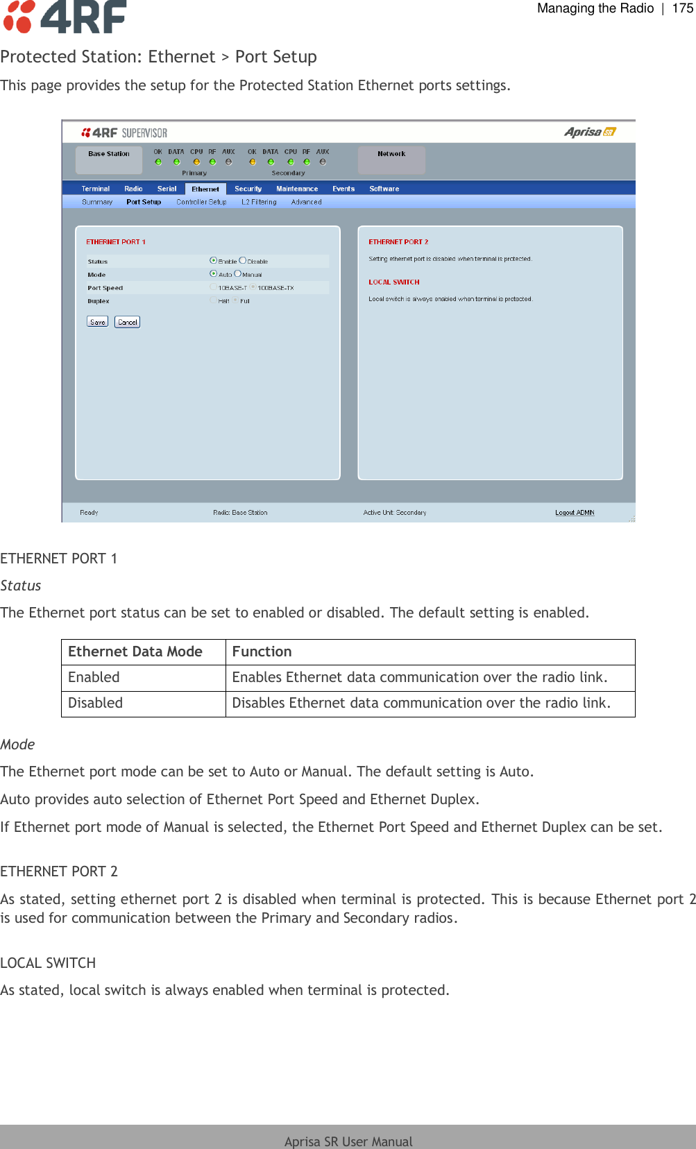
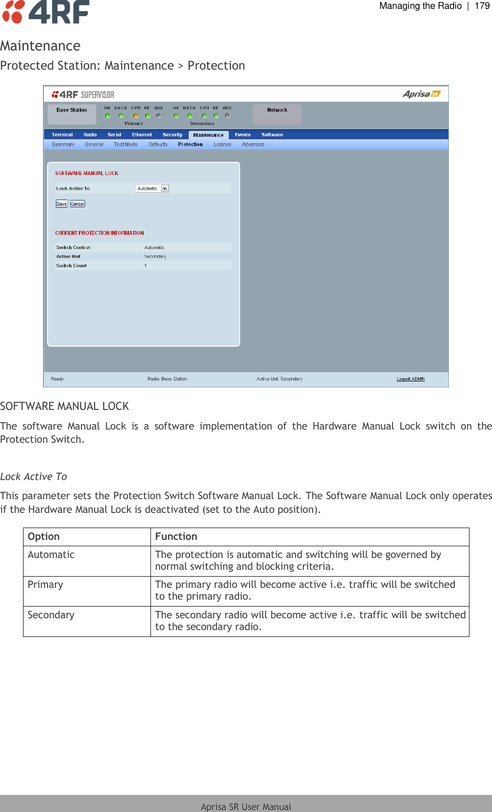
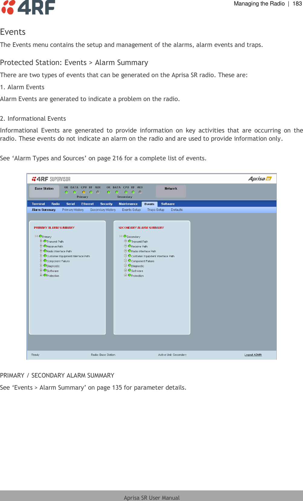
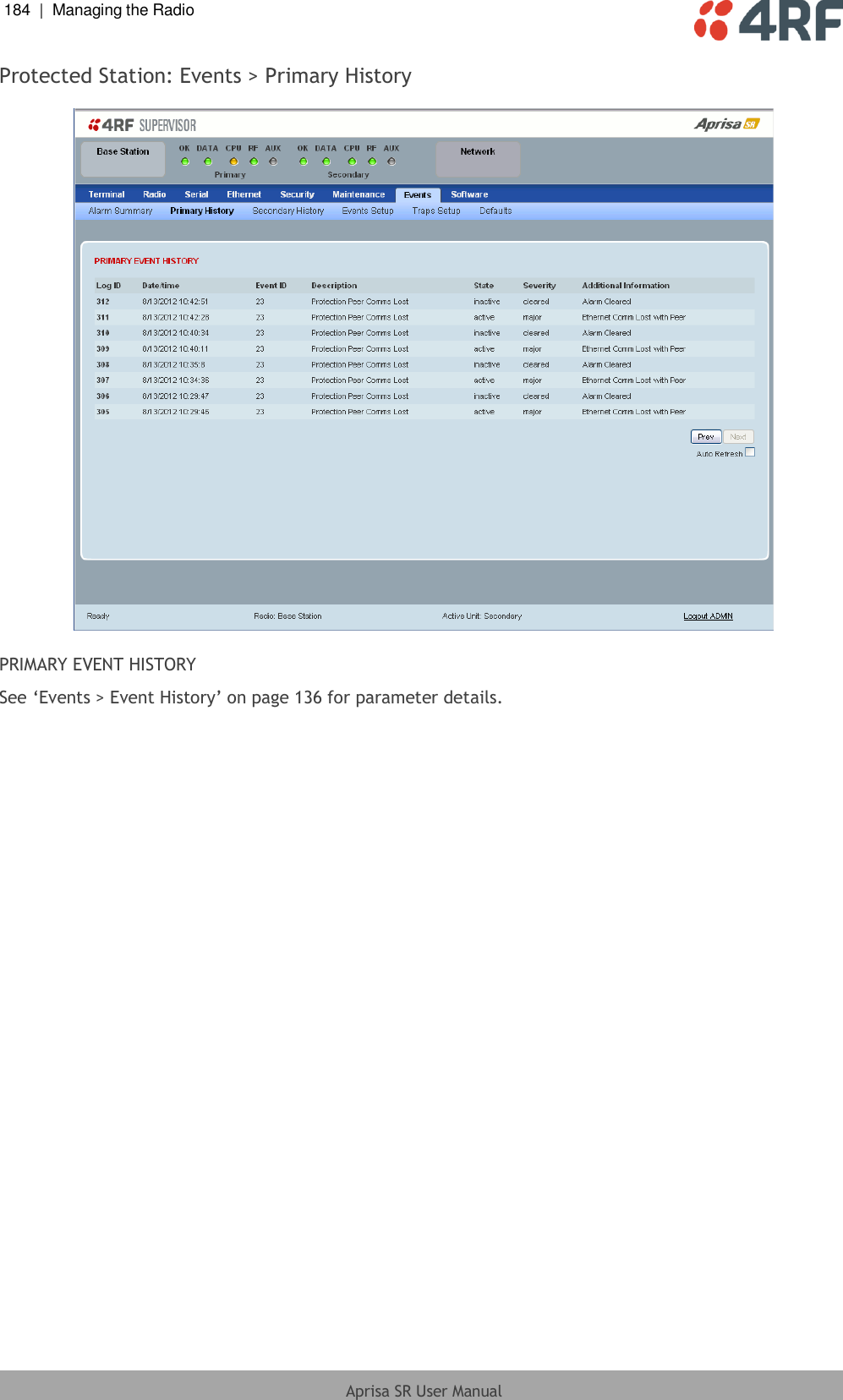
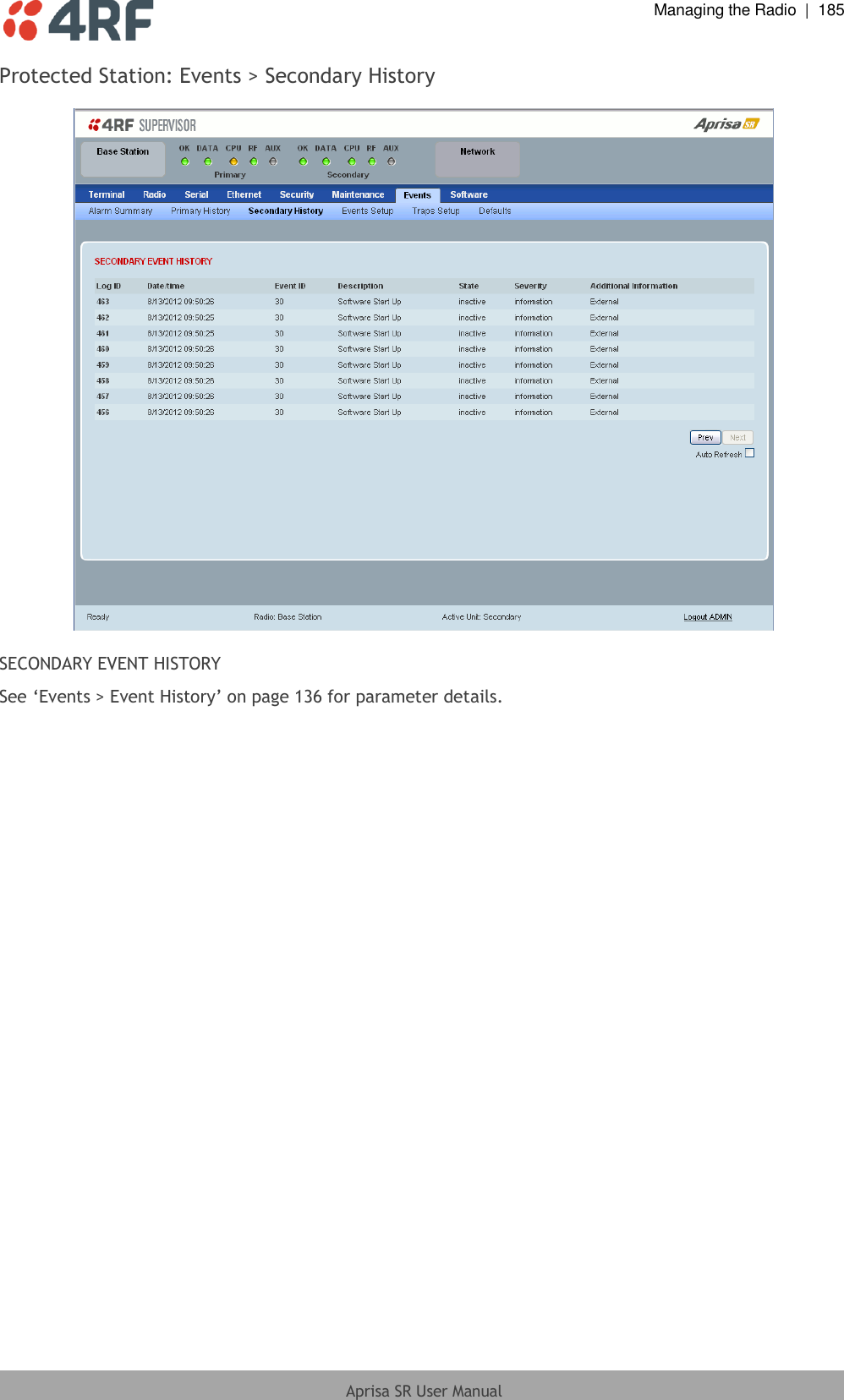
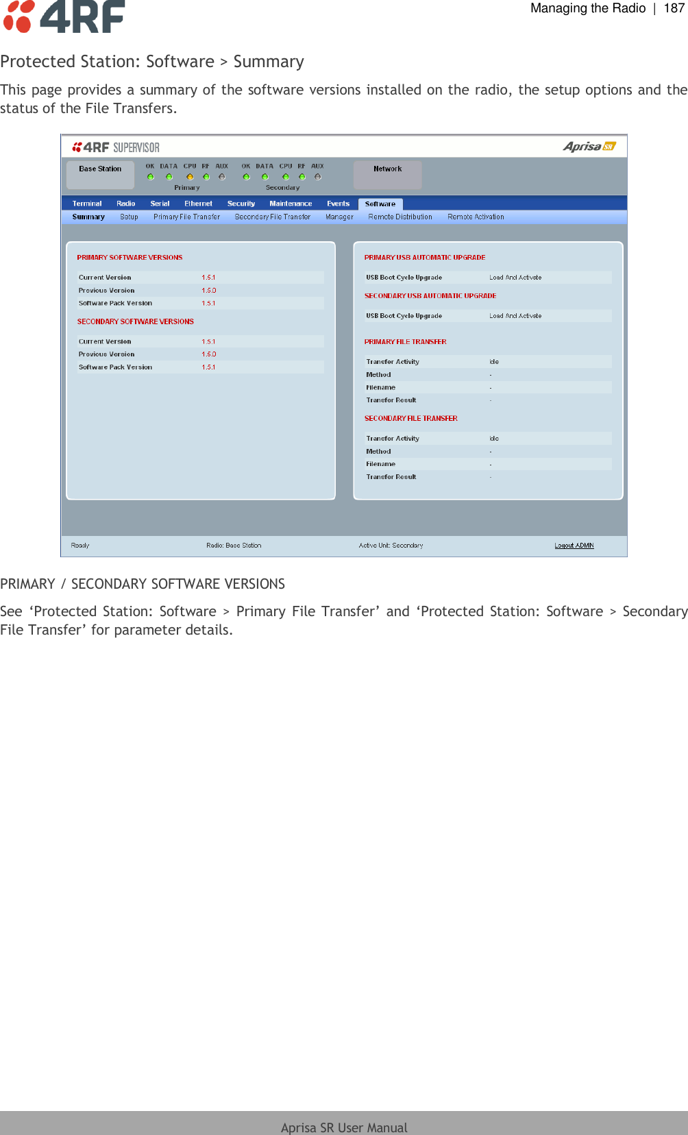
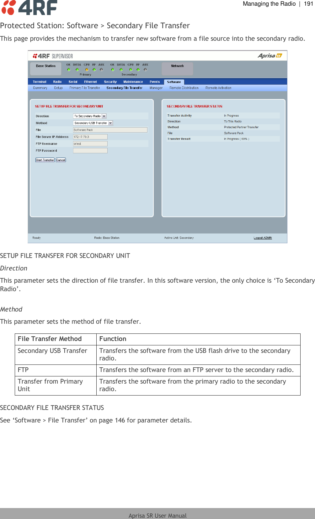
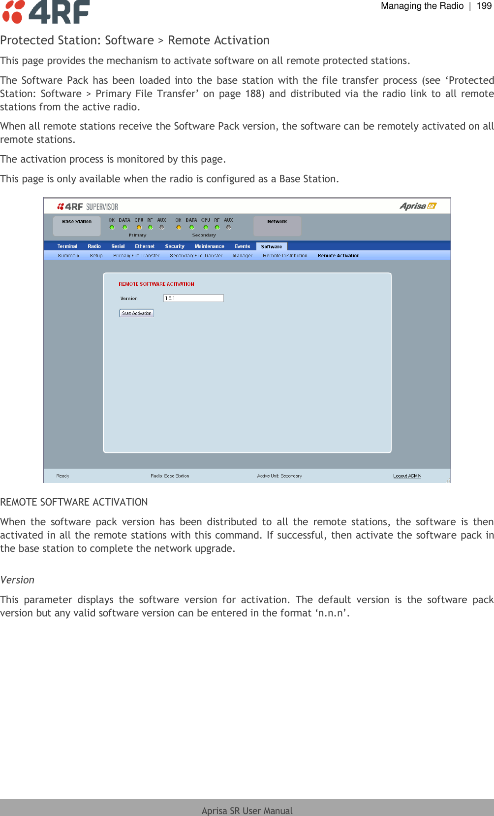
![110 | Managing the Radio Aprisa SR User Manual Payload Encryption Key Type This parameter sets the Payload Encryption Key Type: Payload Encryption Key Type Function Pass Phrase Use the Pass Phrase password format for standard security. Raw Hexidecimal Use the Raw Hexidecimal password format for better security. It must comply with the specified encryption key size e.g. if Encryption Type to AES128, the encryption key must be 16 bytes (32 chars) The default setting is Pass Phrase. Payload Encryption Key Size This parameter sets the Encryption Type to AES128, AES192 or AES256. The default setting is AES128. The higher the encryption size the better the security. Payload Encryption Key This parameter sets the Payload Encryption password. This key is used to encrypt the payload. Pass Phrase Good password policy: contains at least eight characters, and contains at least one upper case letter, and contains at least one lower case letter, and contains at least one digit or another character such as !@#$%^&(){}[]<>... , and is not a term in a familiar language or jargon, and is not identical to or derived from the accompanying account name, from personal characteristics or from information from one’s family/social circle, and is easy to remember, for instance by means of a key sentence Raw Hexidecimal The Raw Hexidecimal password must comply with the specified encryption key size e.g. if Encryption Type to AES128, the encryption key must be 16 bytes (32 chars).](https://usermanual.wiki/4RF/SRN0400025A/User-Guide-2013875-Page-112.png)
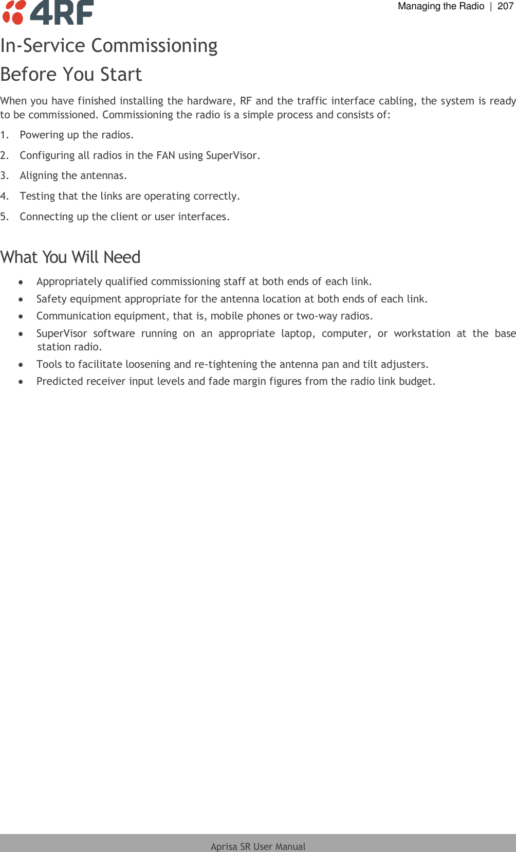
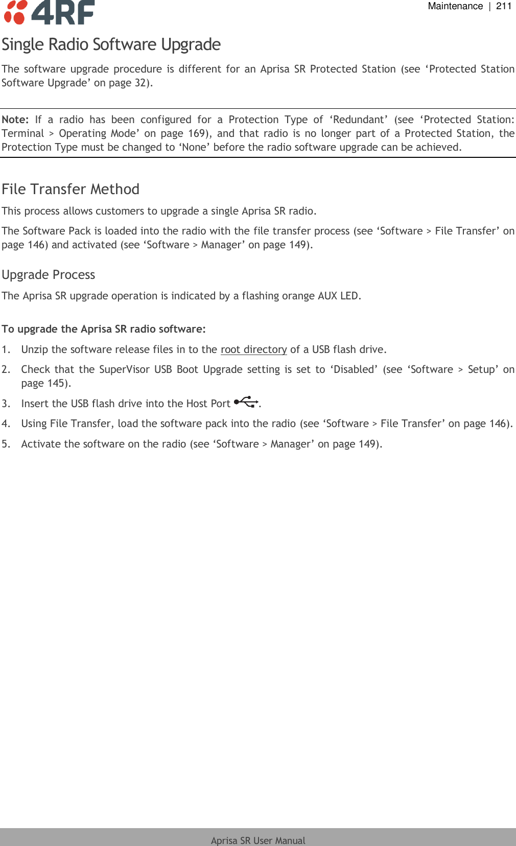
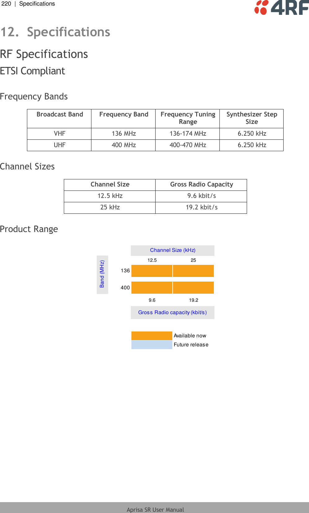
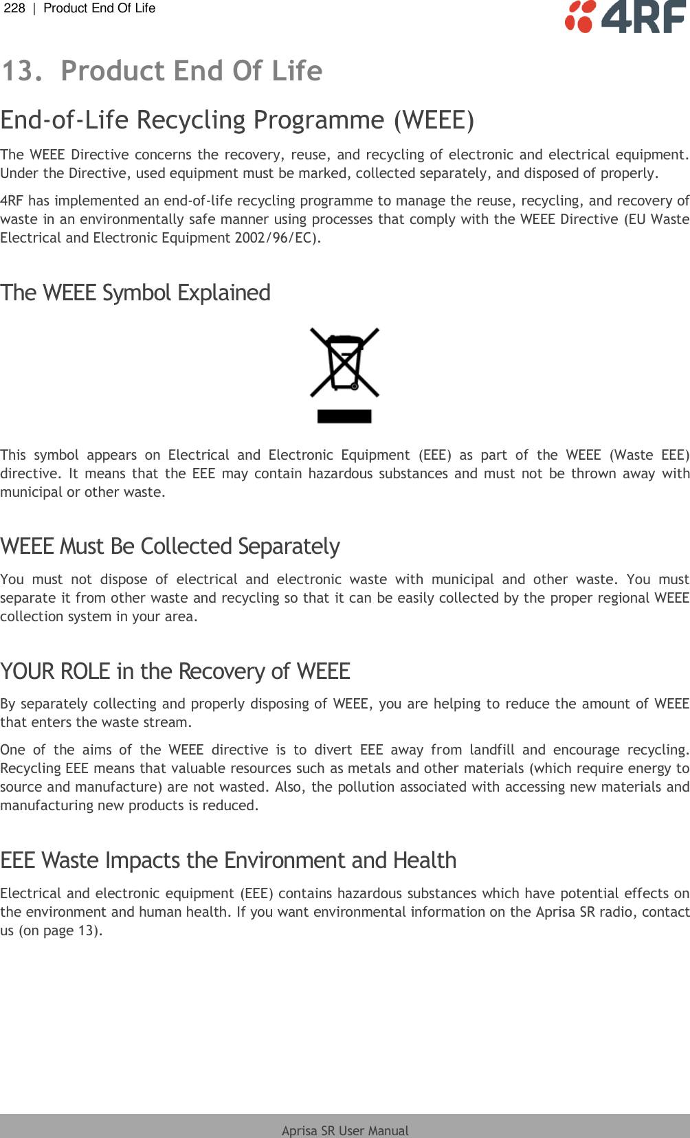
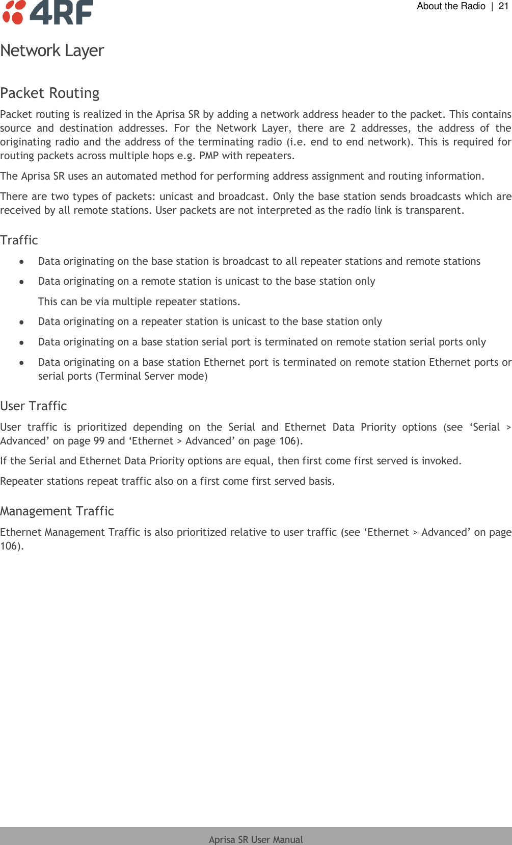
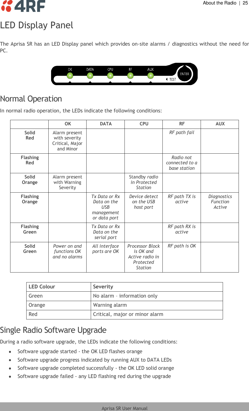
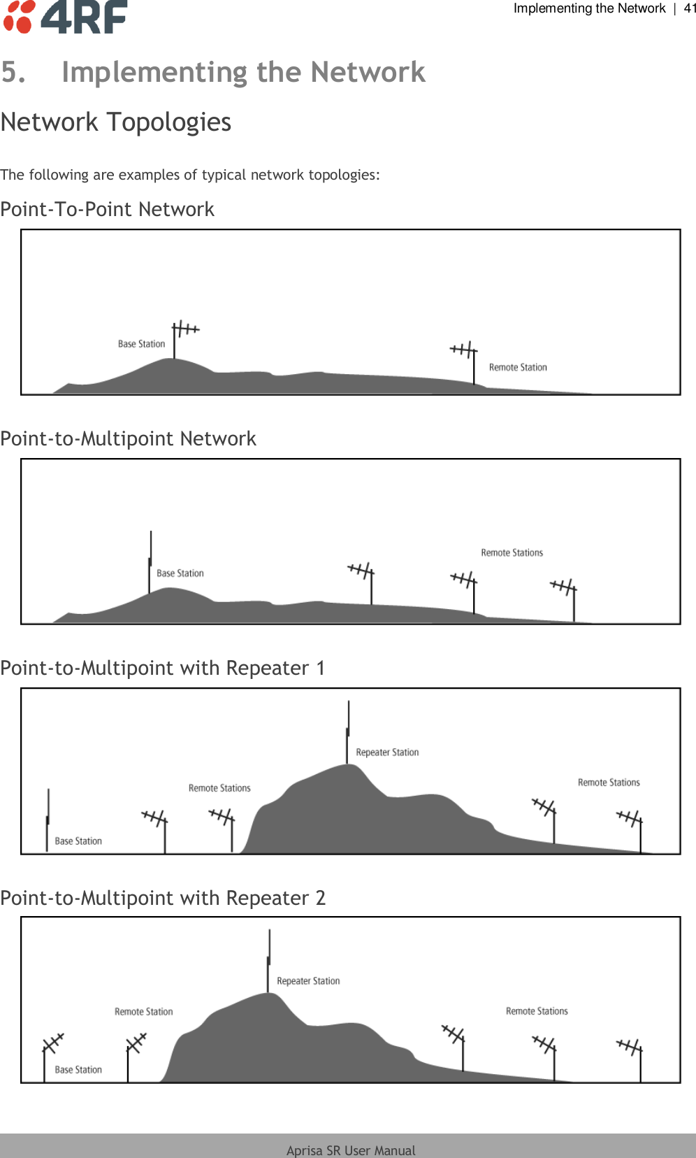
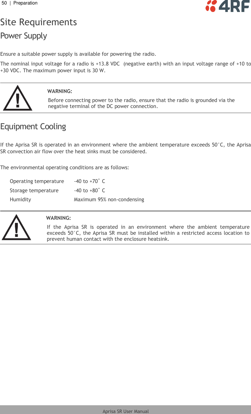
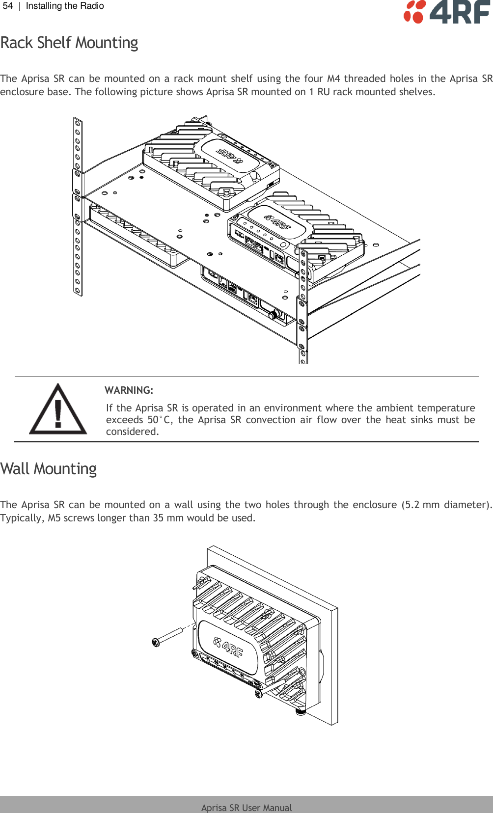
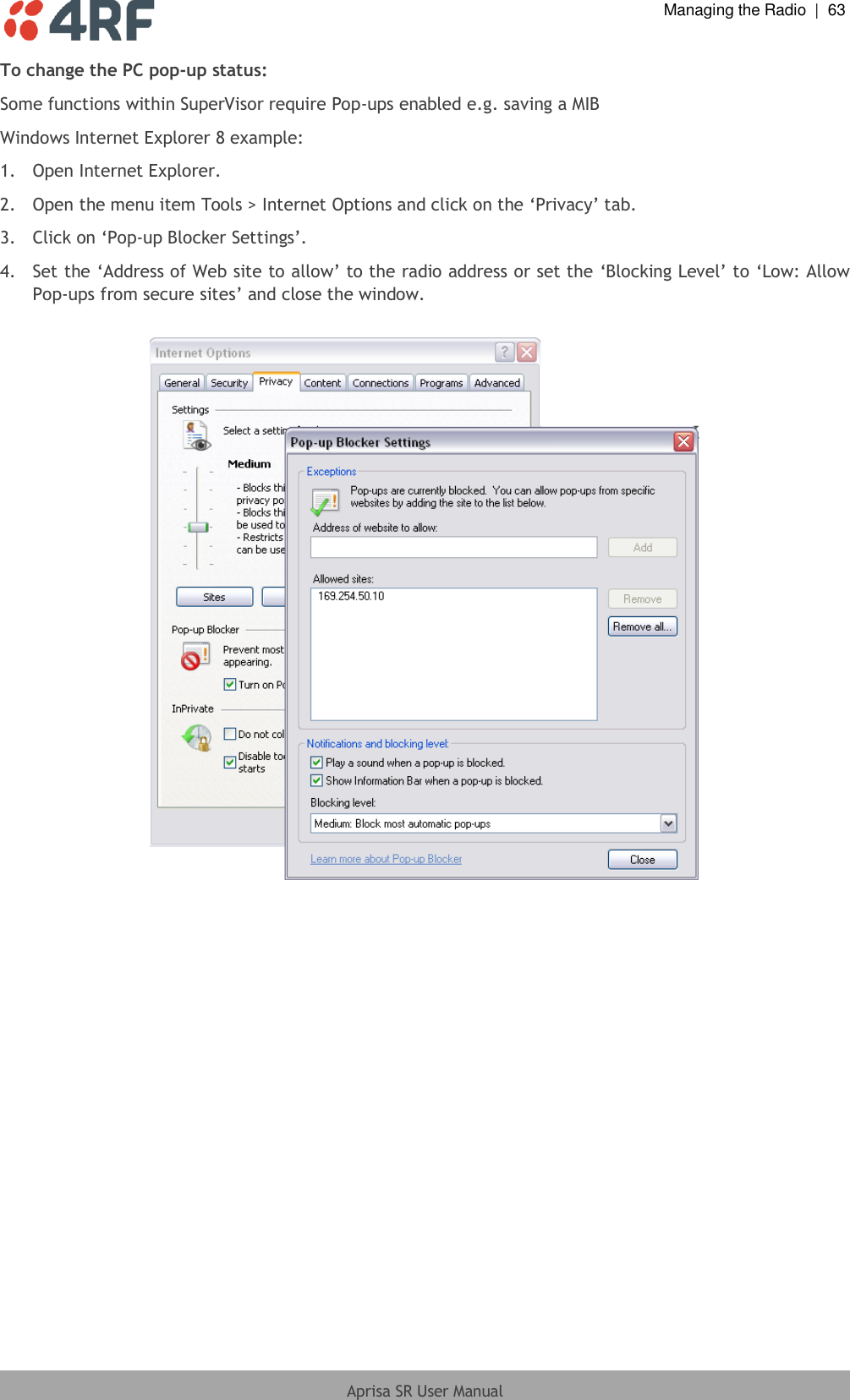
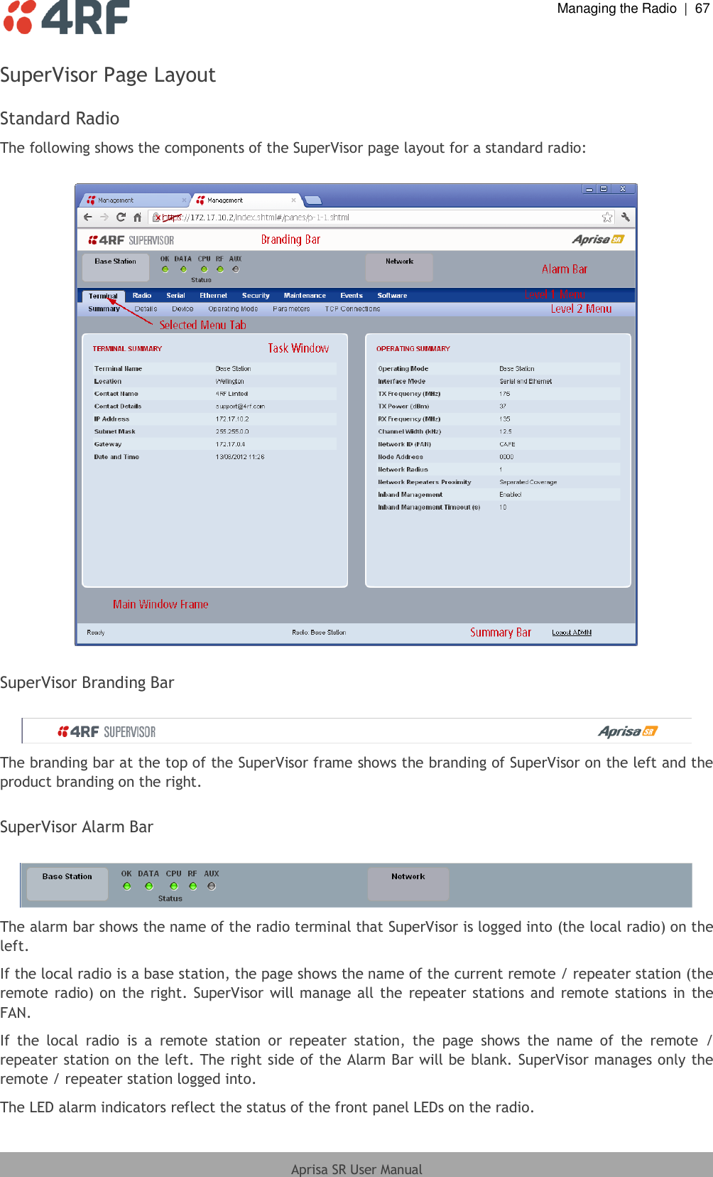
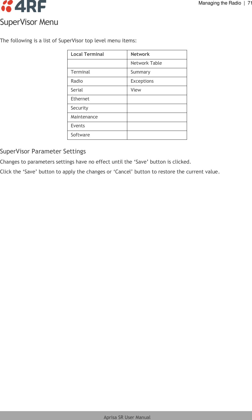
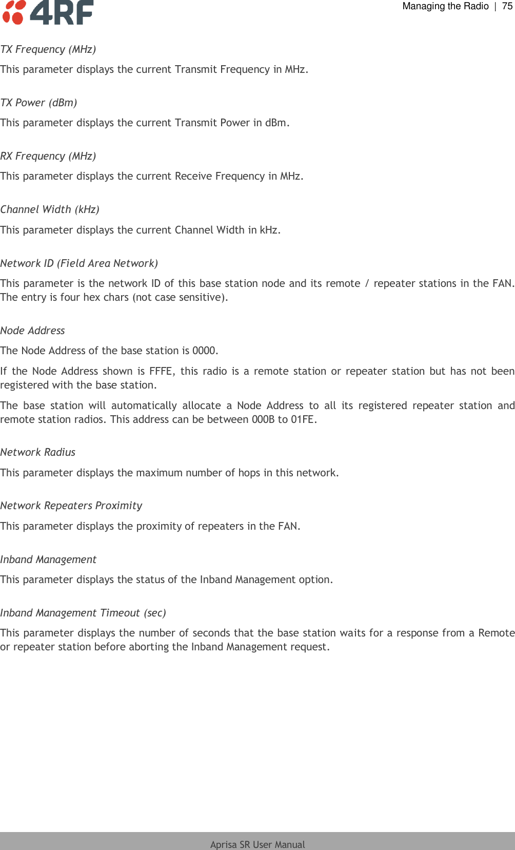
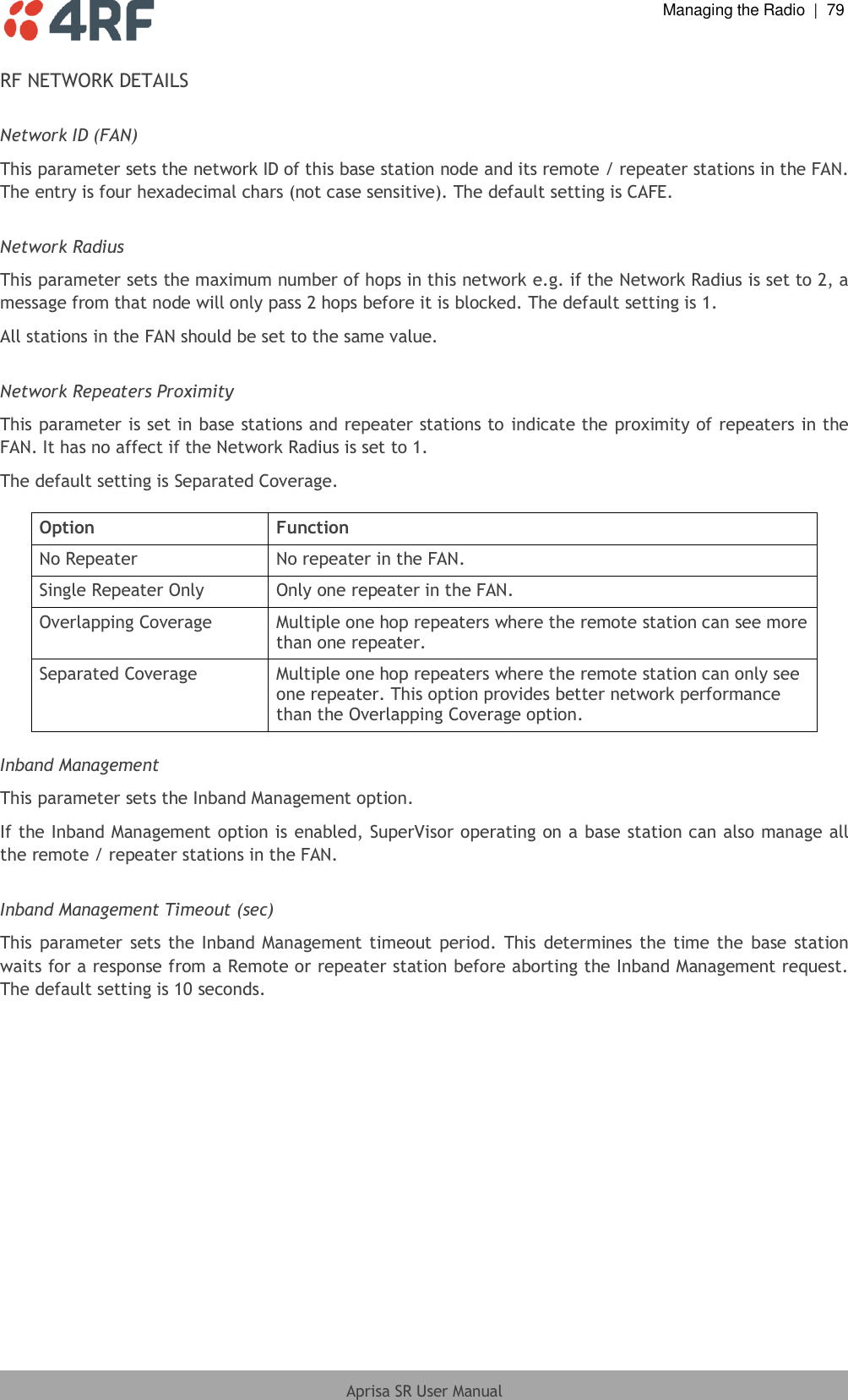
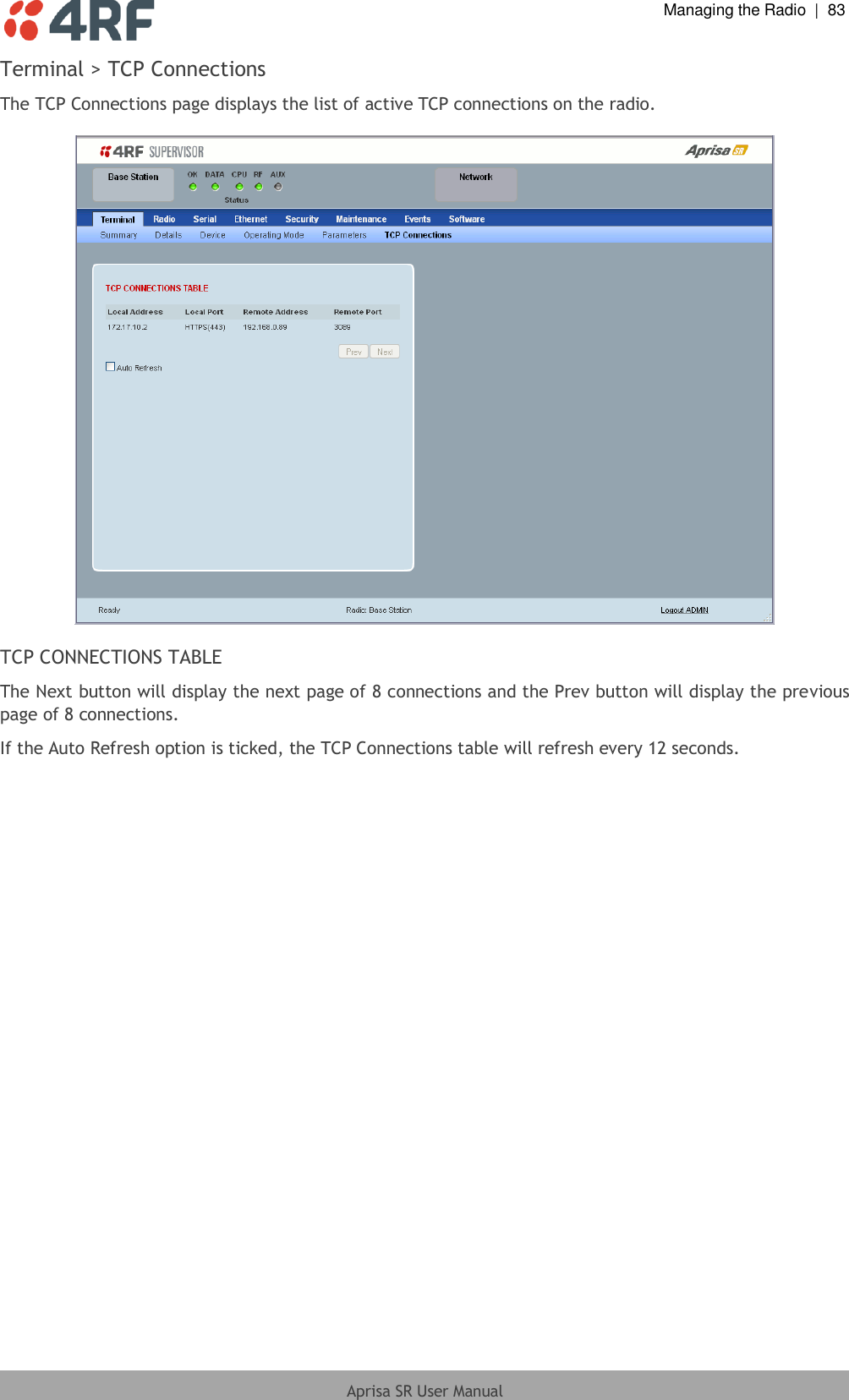
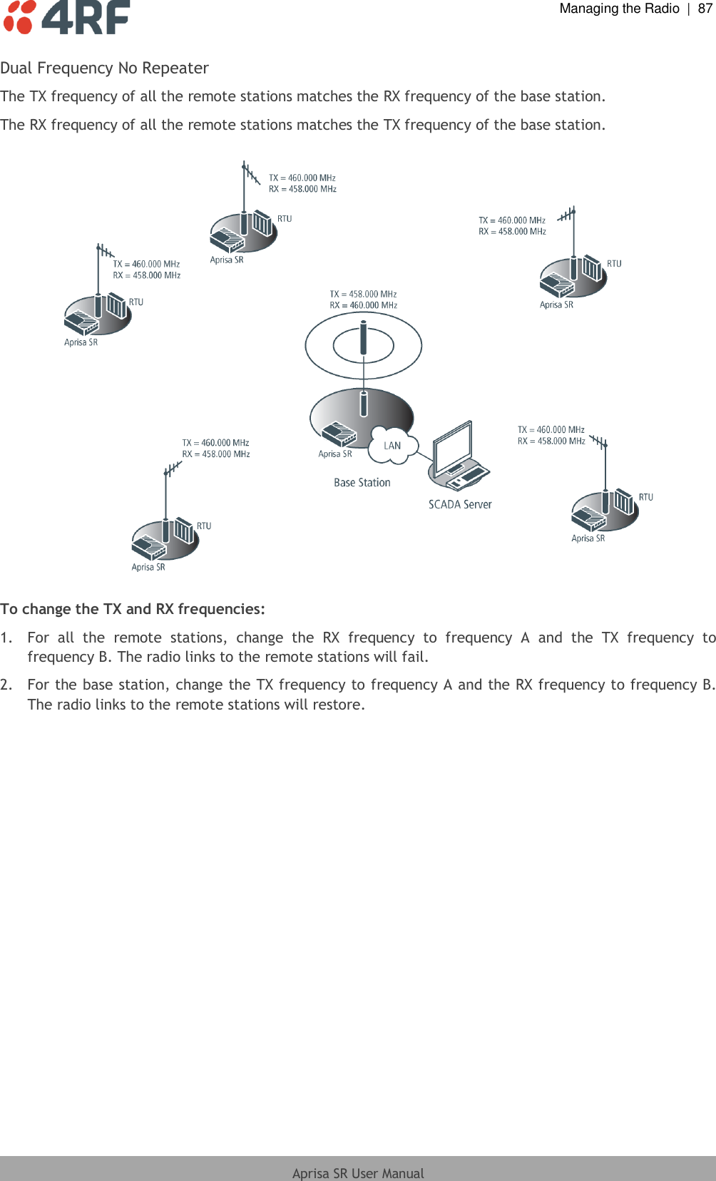
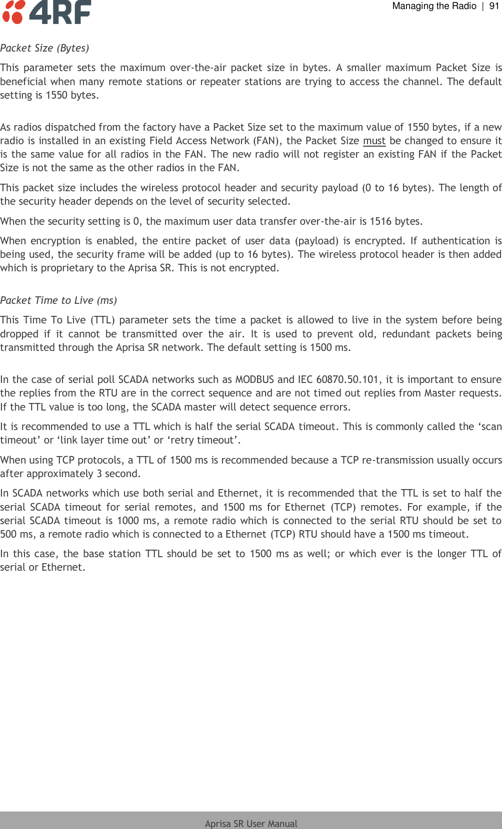
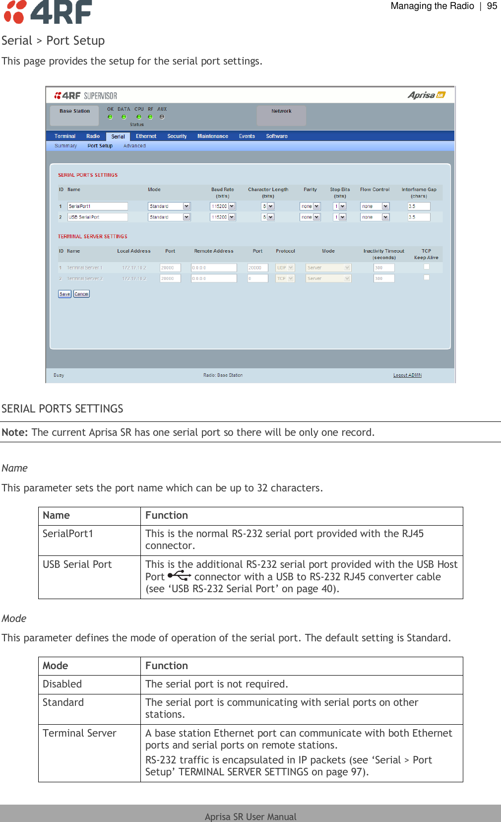
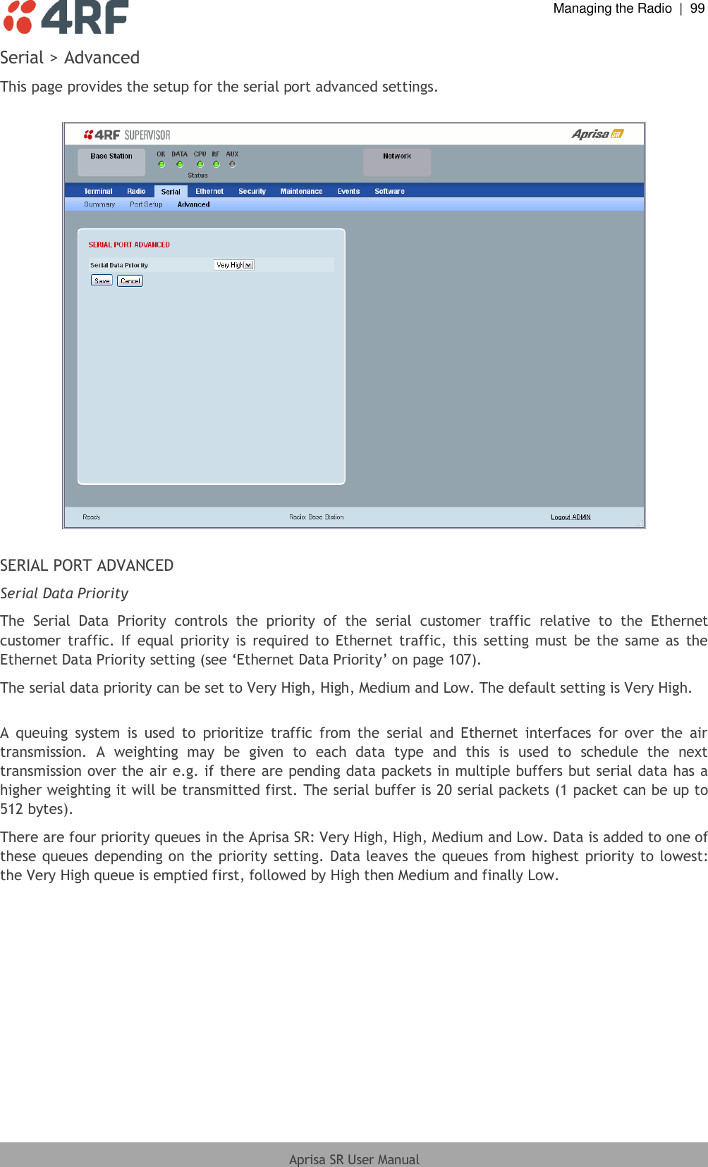
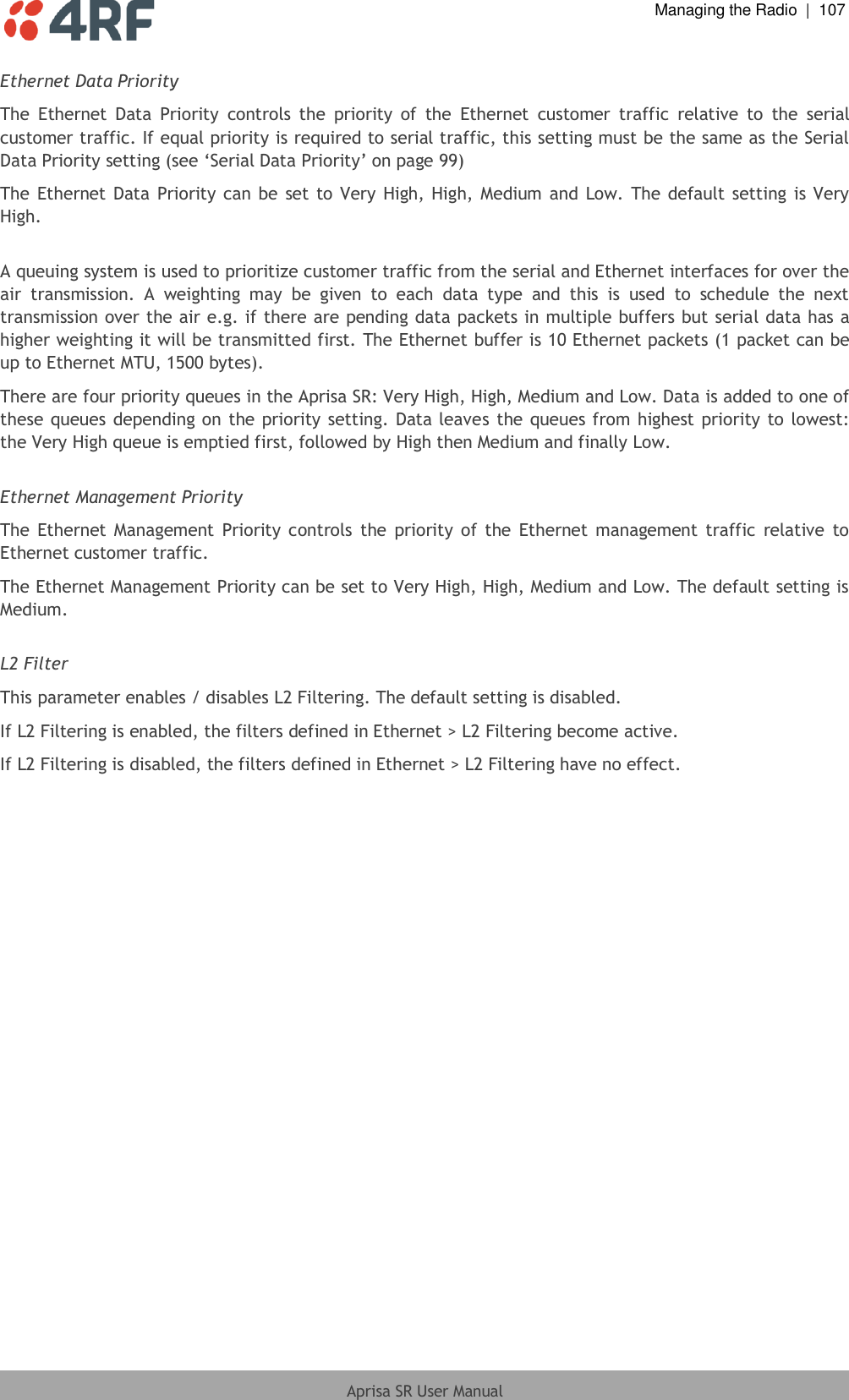
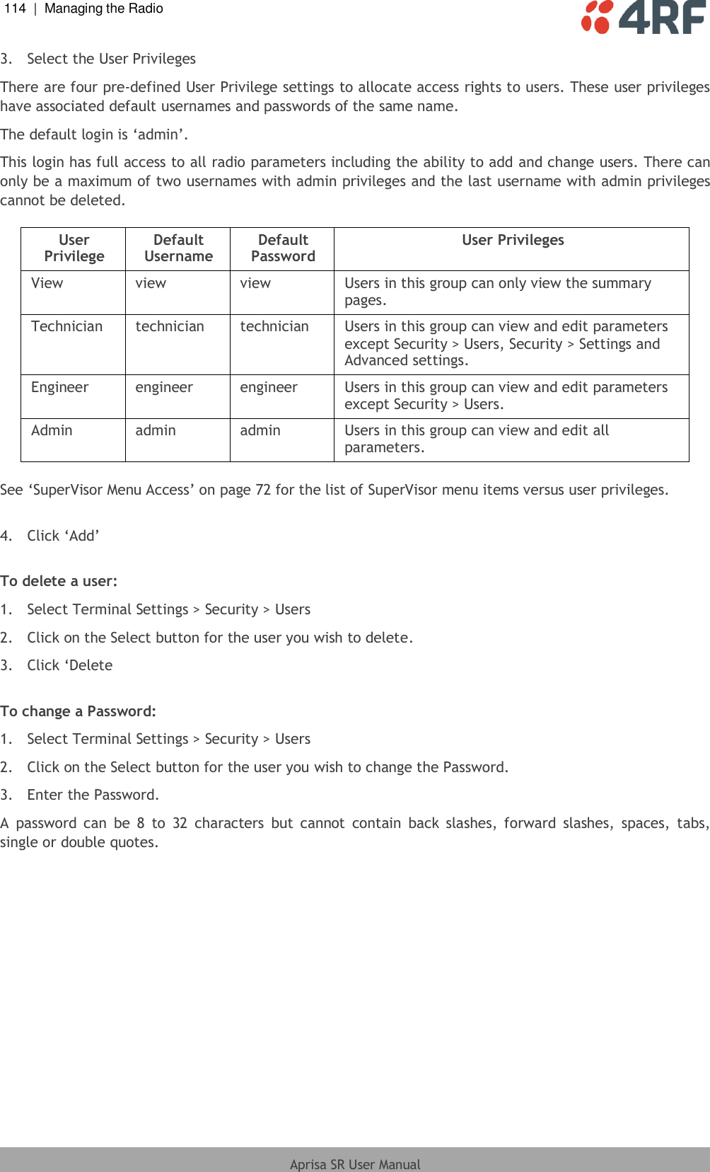
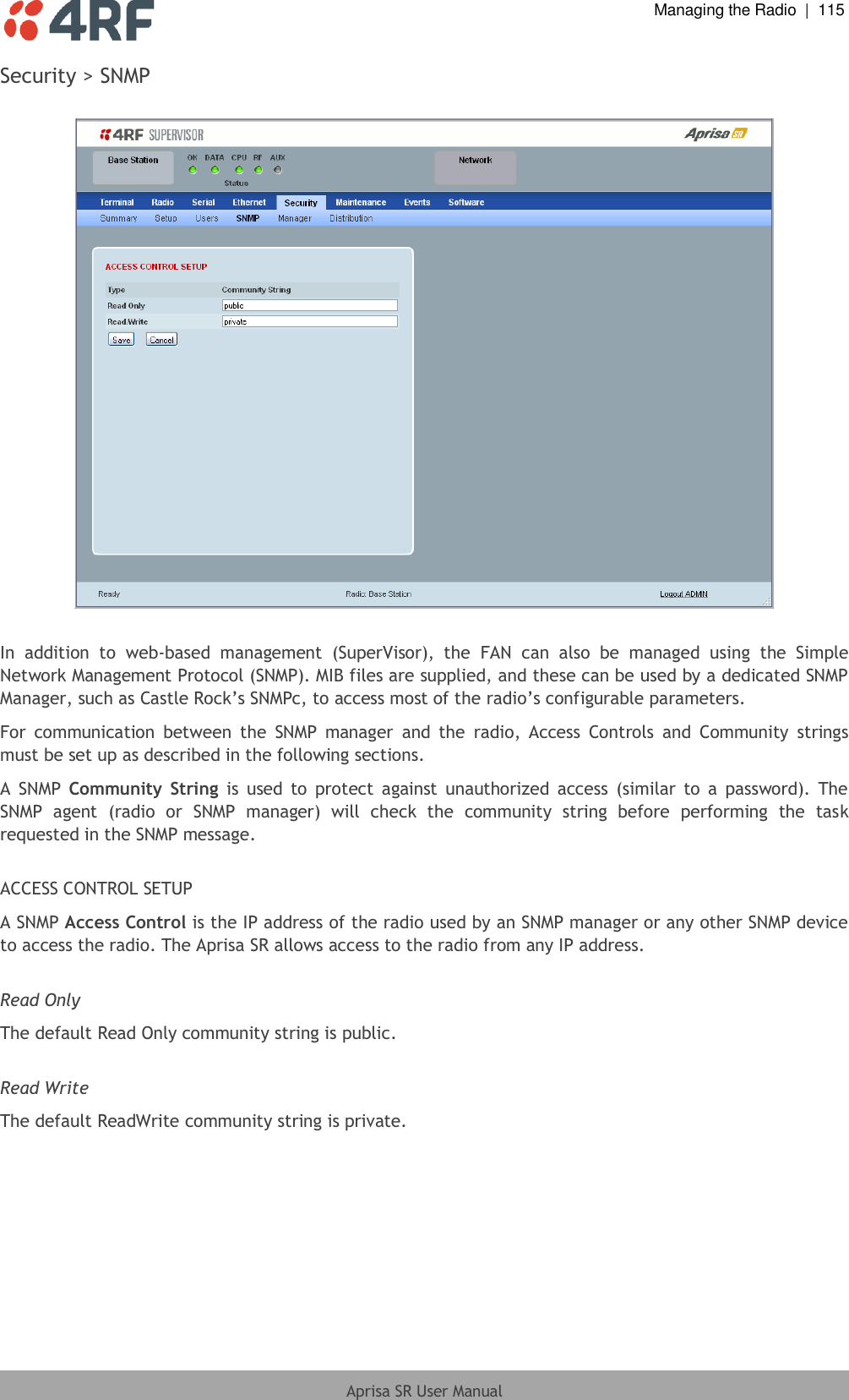
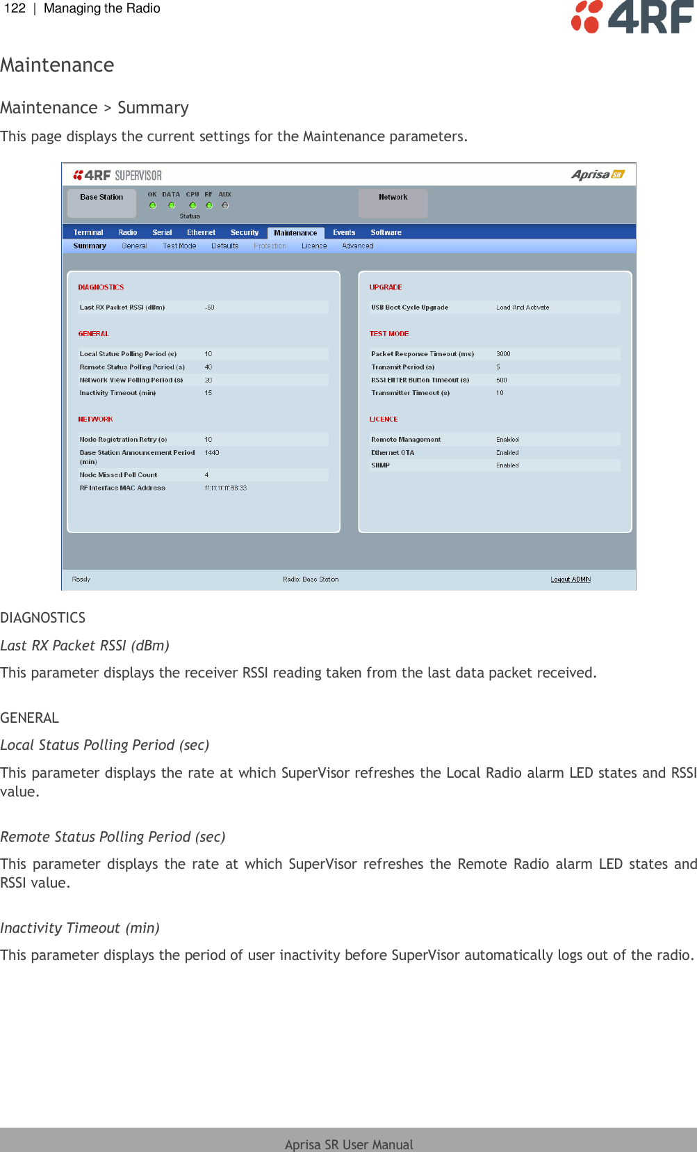
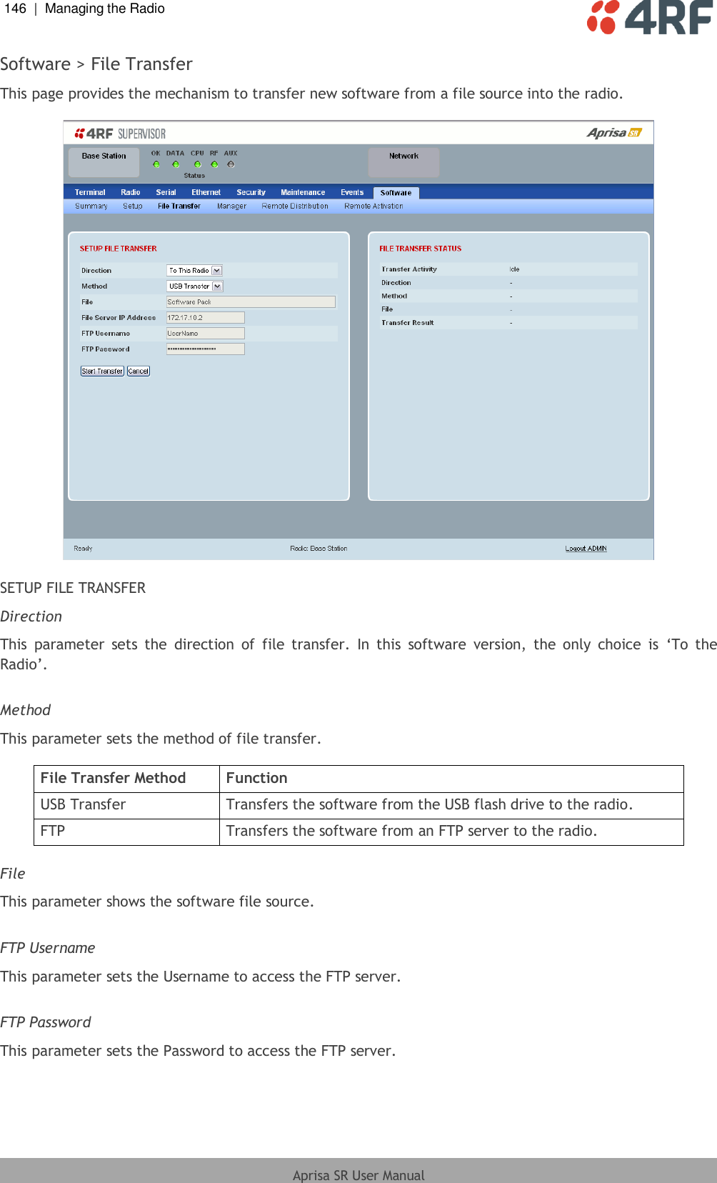
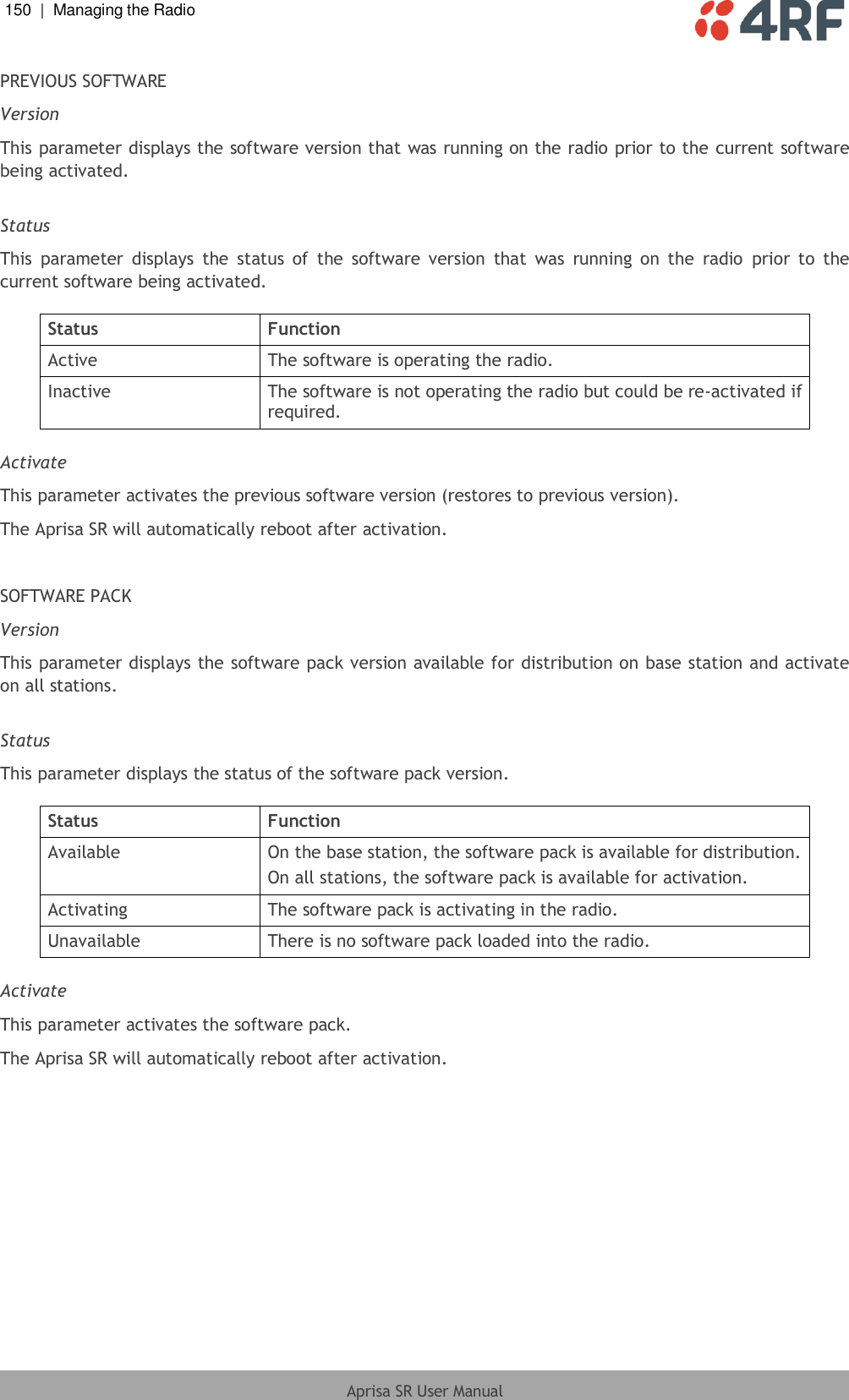
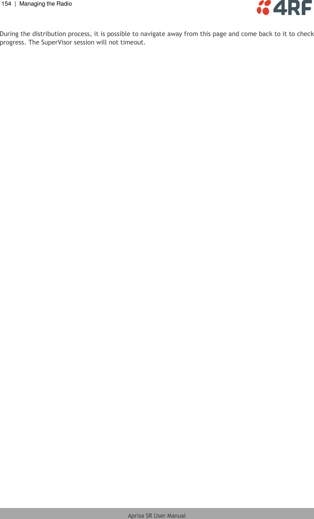
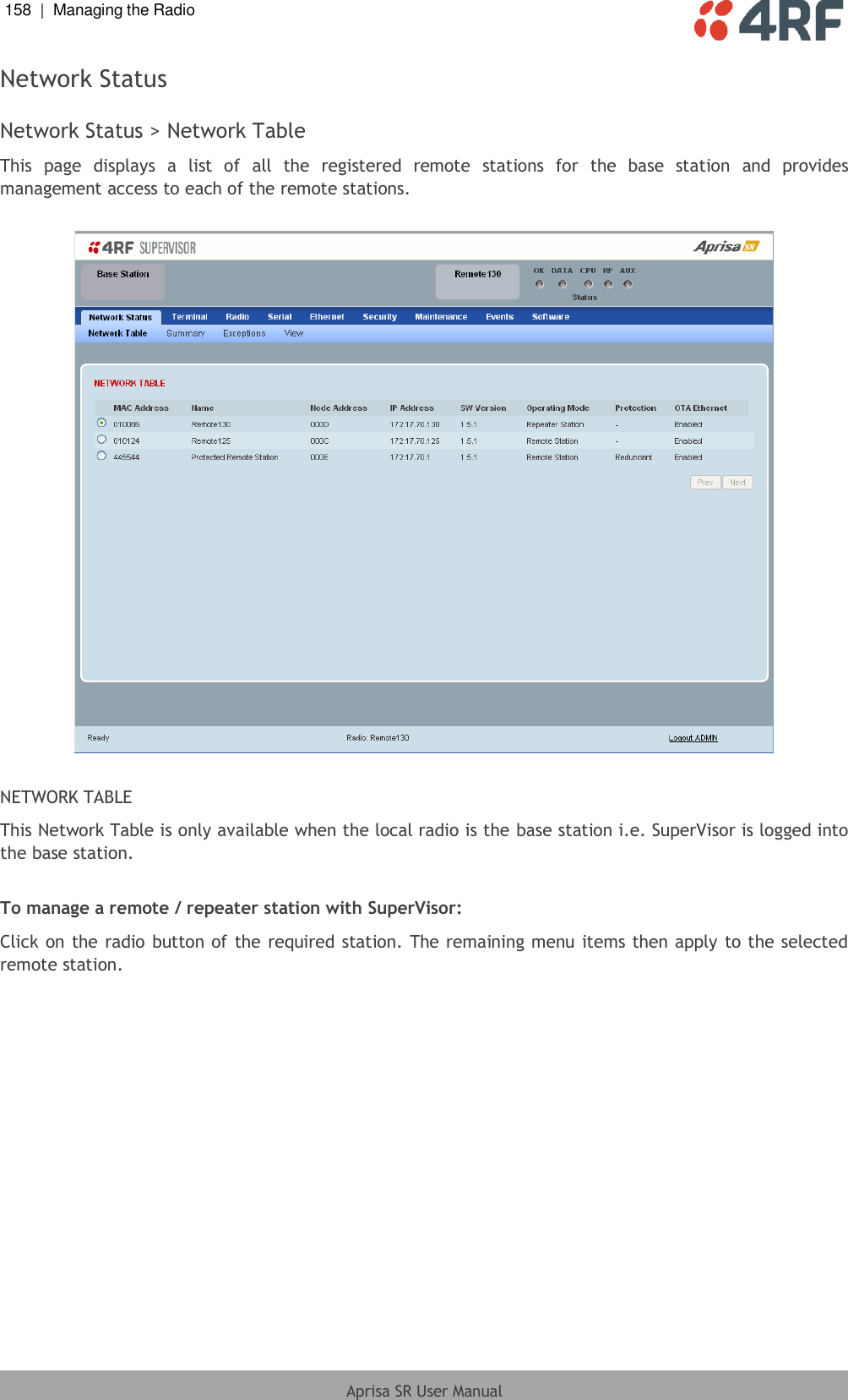
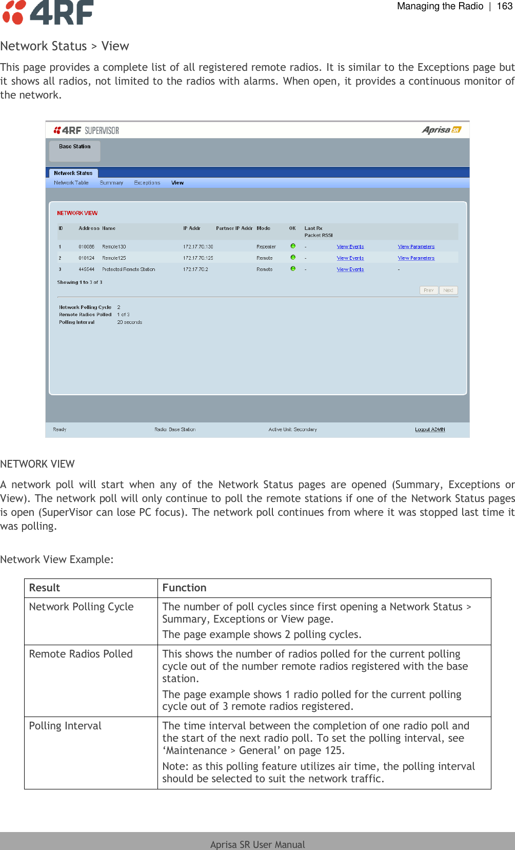
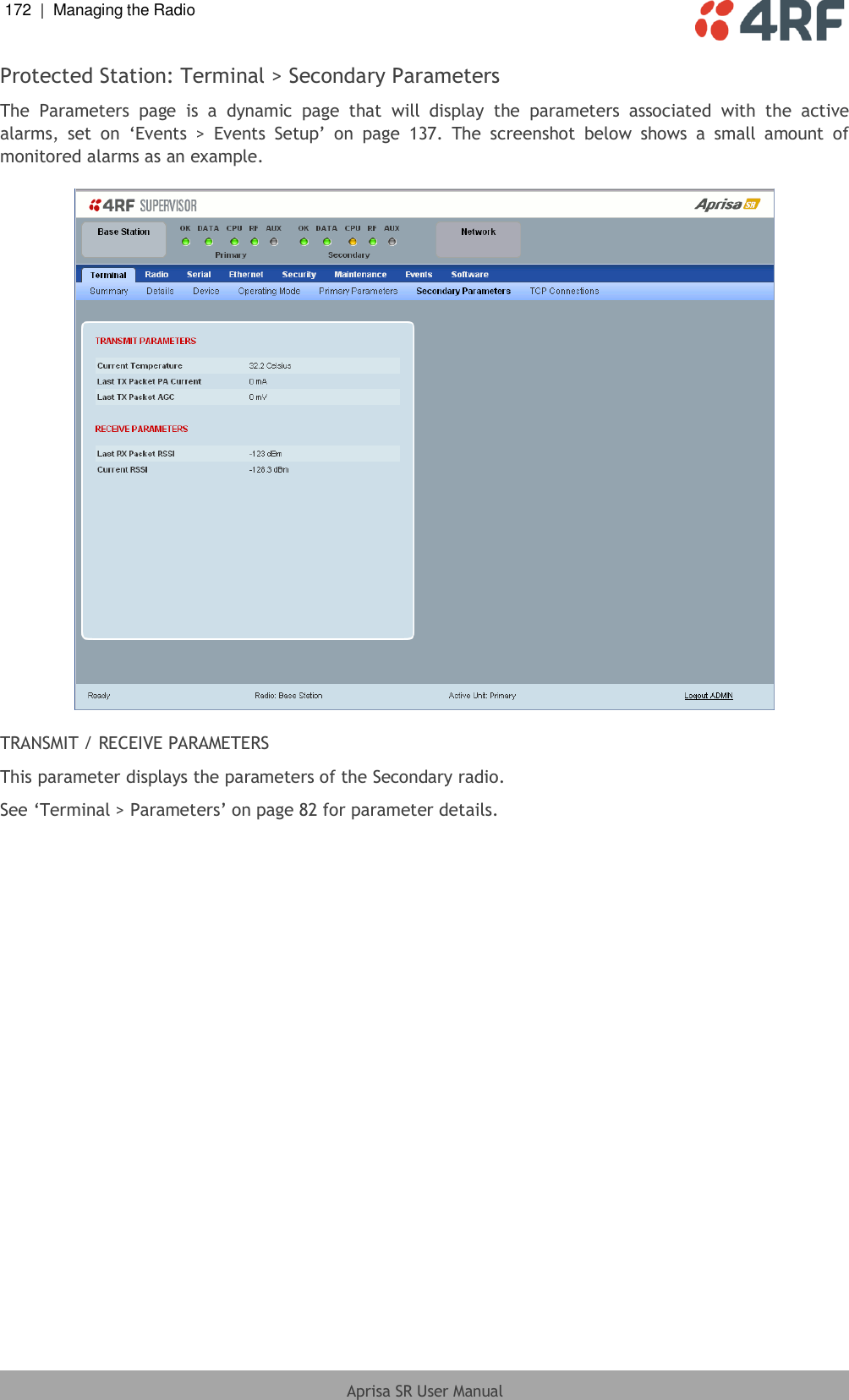
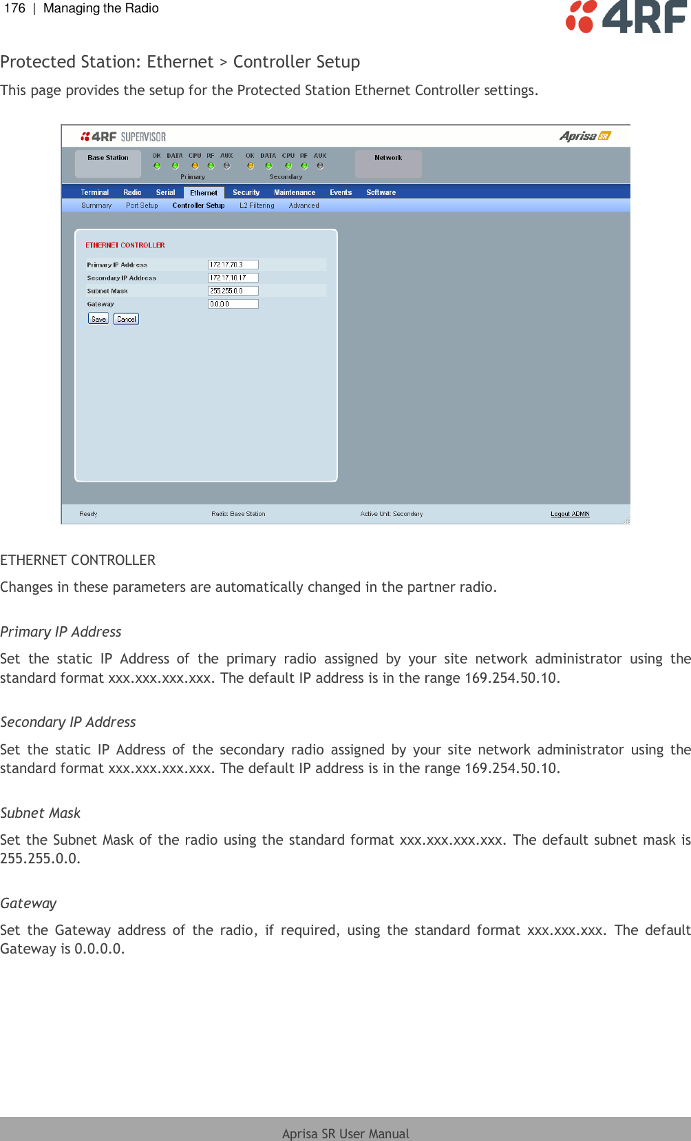
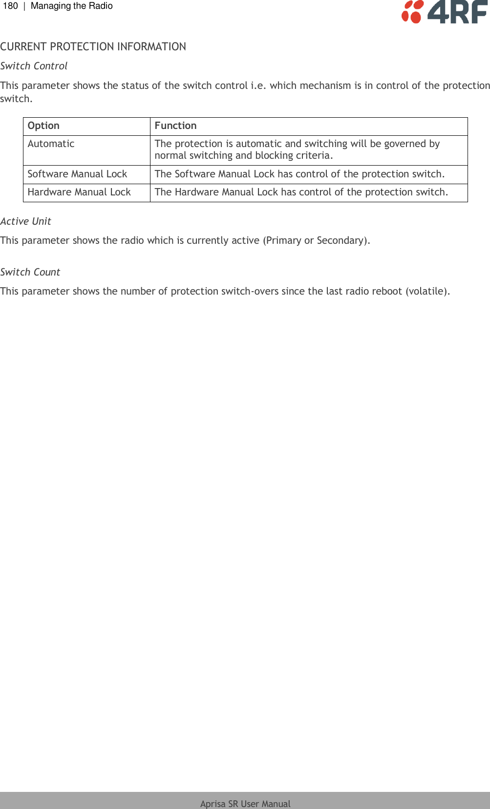
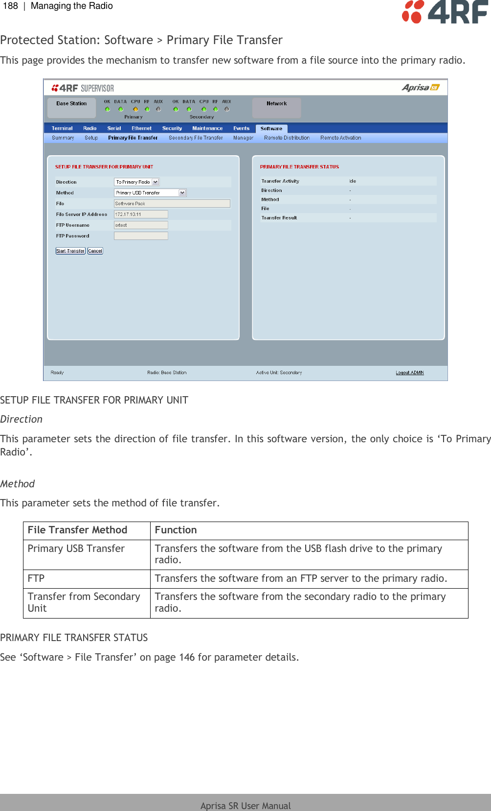
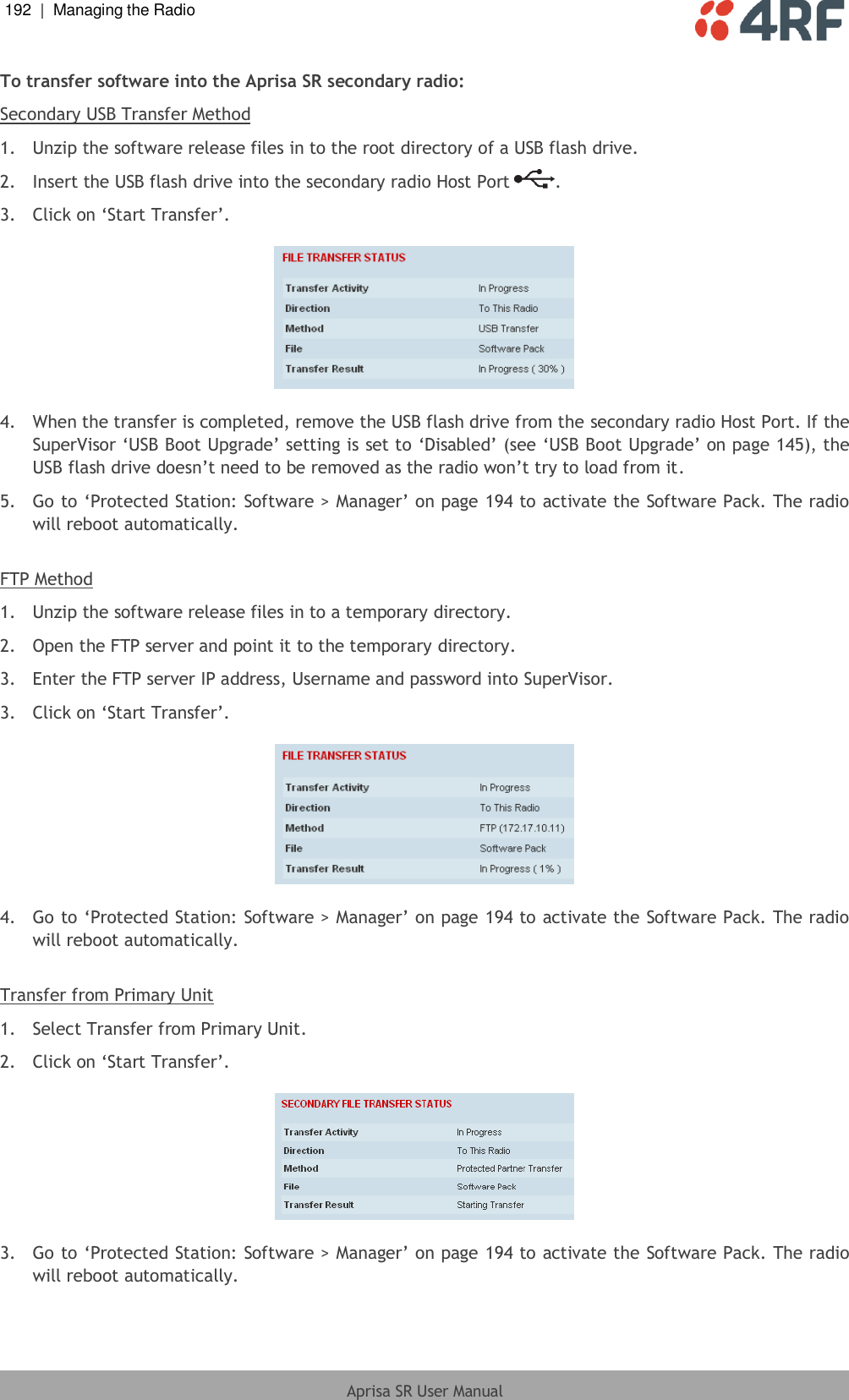
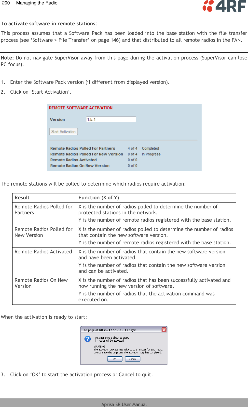
![Managing the Radio | 113 Aprisa SR User Manual Security > Users Note: You must login with ‘admin’ privileges to add, disable, delete a user or change a password. USER DETAILS Shows a list of the current users setup in the radio. ADD NEW USER To add a new user: 1. Enter the Username. A username can be up to 32 characters but cannot contain back slashes, forward slashes, spaces, tabs, single or double quotes. Usernames are case sensitive. 2. Enter the Password. A password can be 8 to 32 characters but cannot contain back slashes, forward slashes, spaces, tabs, single or double quotes. Passwords are case sensitive. Good password policy: contains at least eight characters, and contains at least one upper case letter, and contains at least one lower case letter, and contains at least one digit or another character such as !@#$%^&(){}[]<>... , and is not a term in a familiar language or jargon, and is not identical to or derived from the accompanying account name, from personal characteristics or from information from one’s family/social circle, and is easy to remember, for instance by means of a key sentence](https://usermanual.wiki/4RF/SRN0400025A/User-Guide-2013875-Page-115.png)

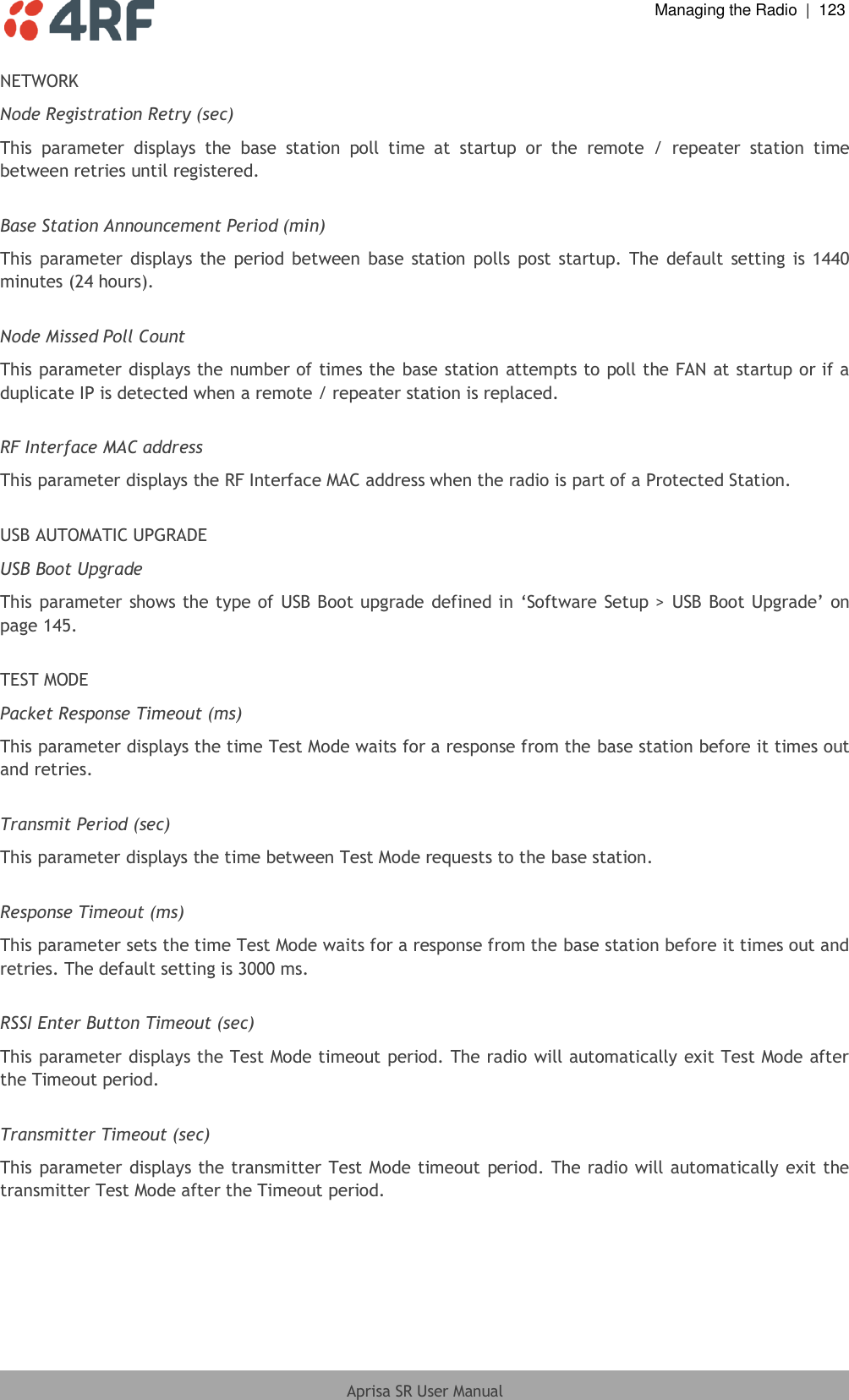
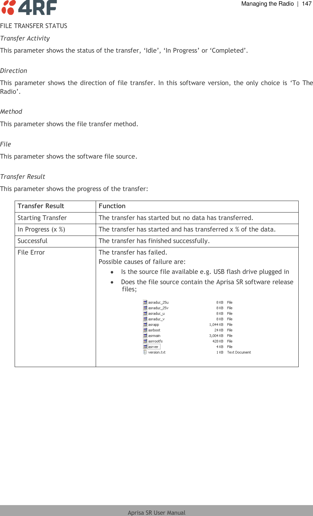
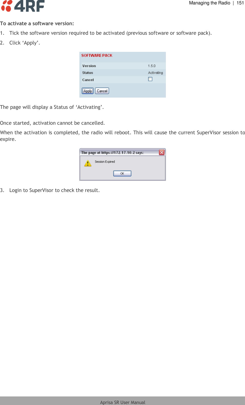
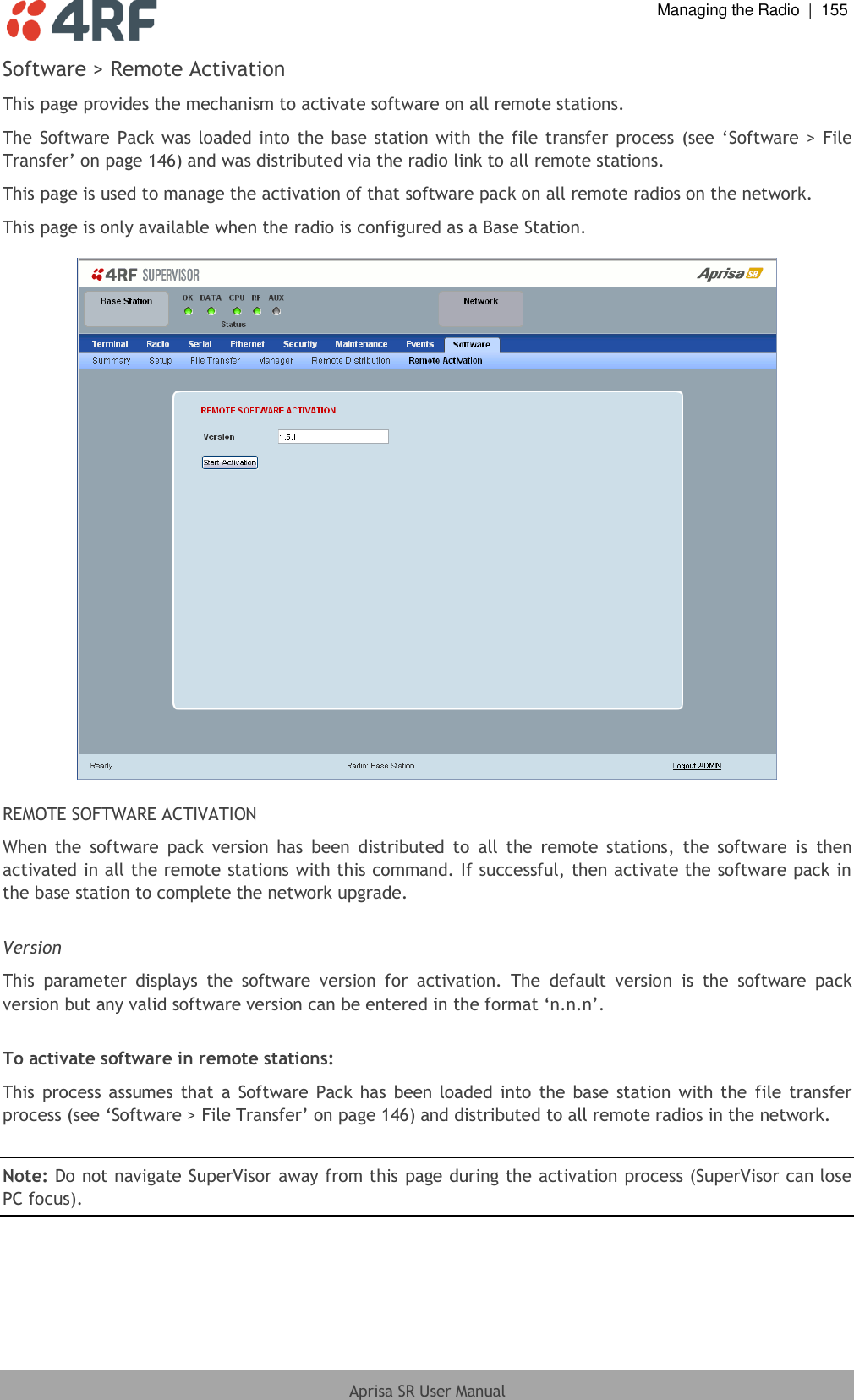
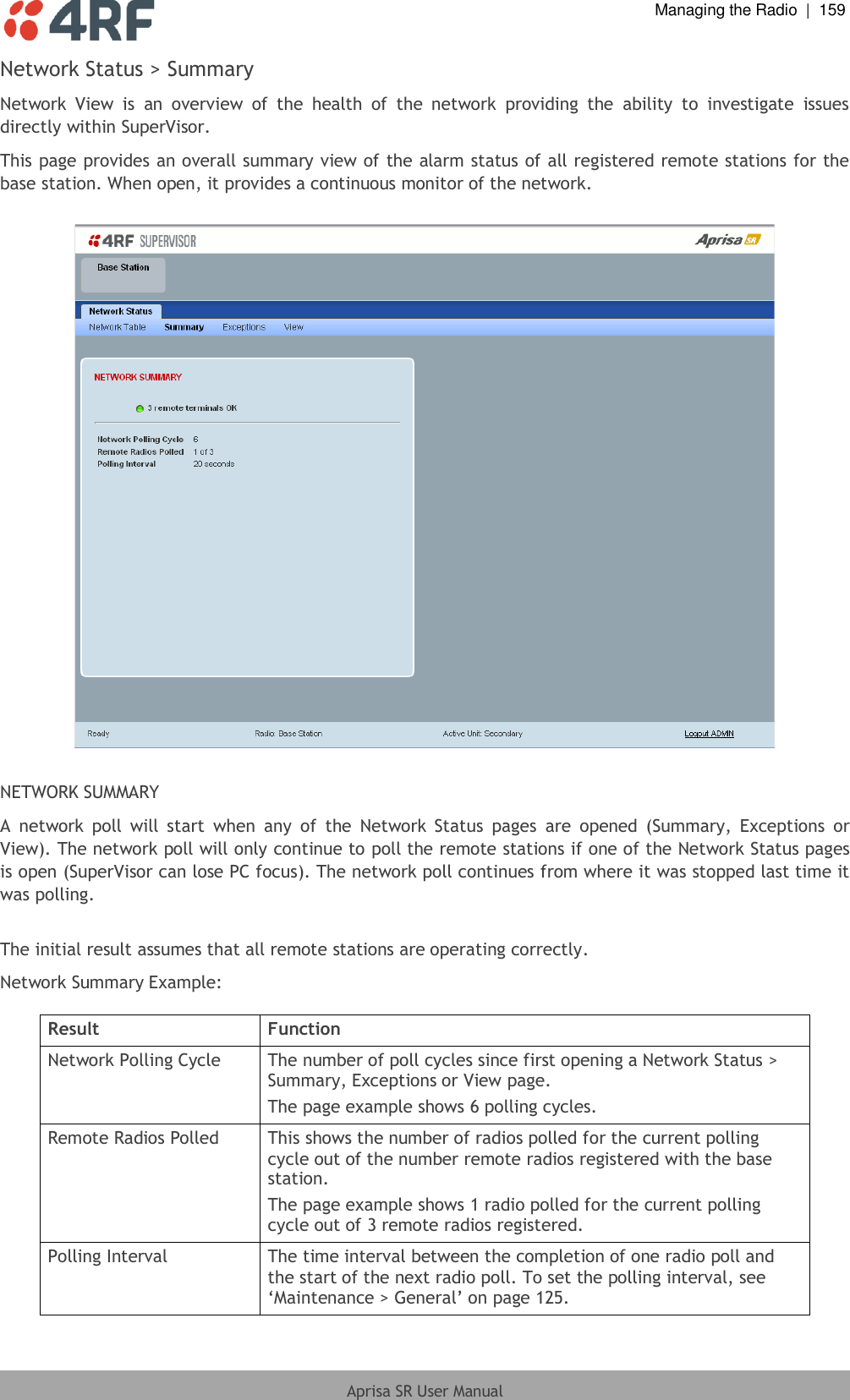

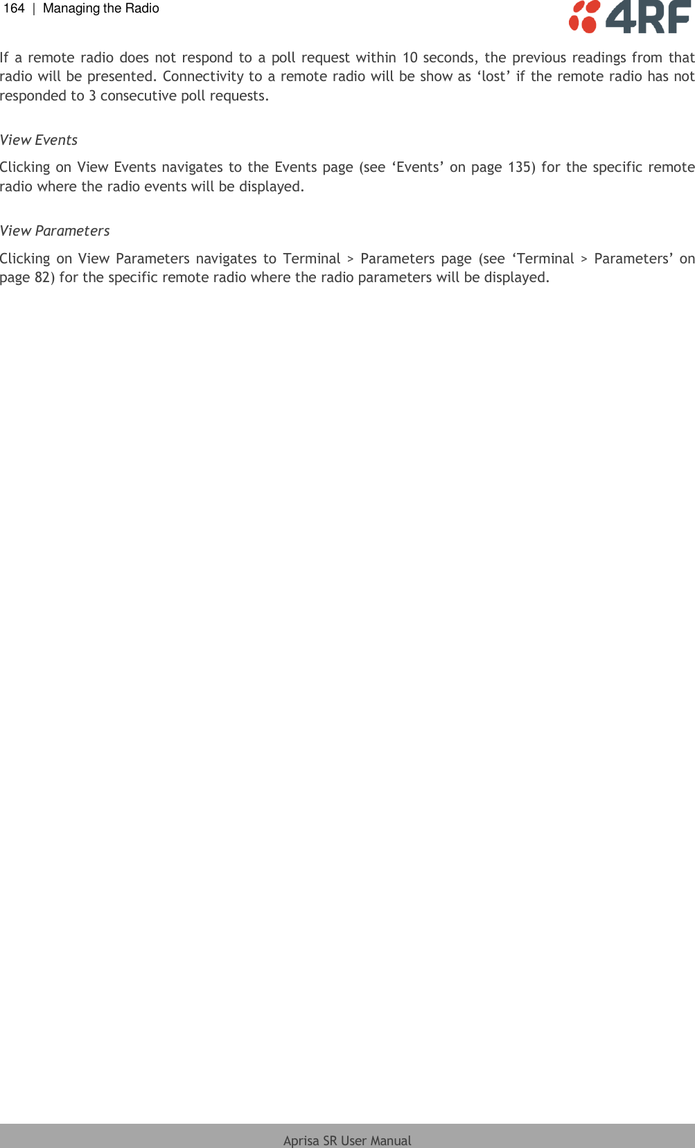

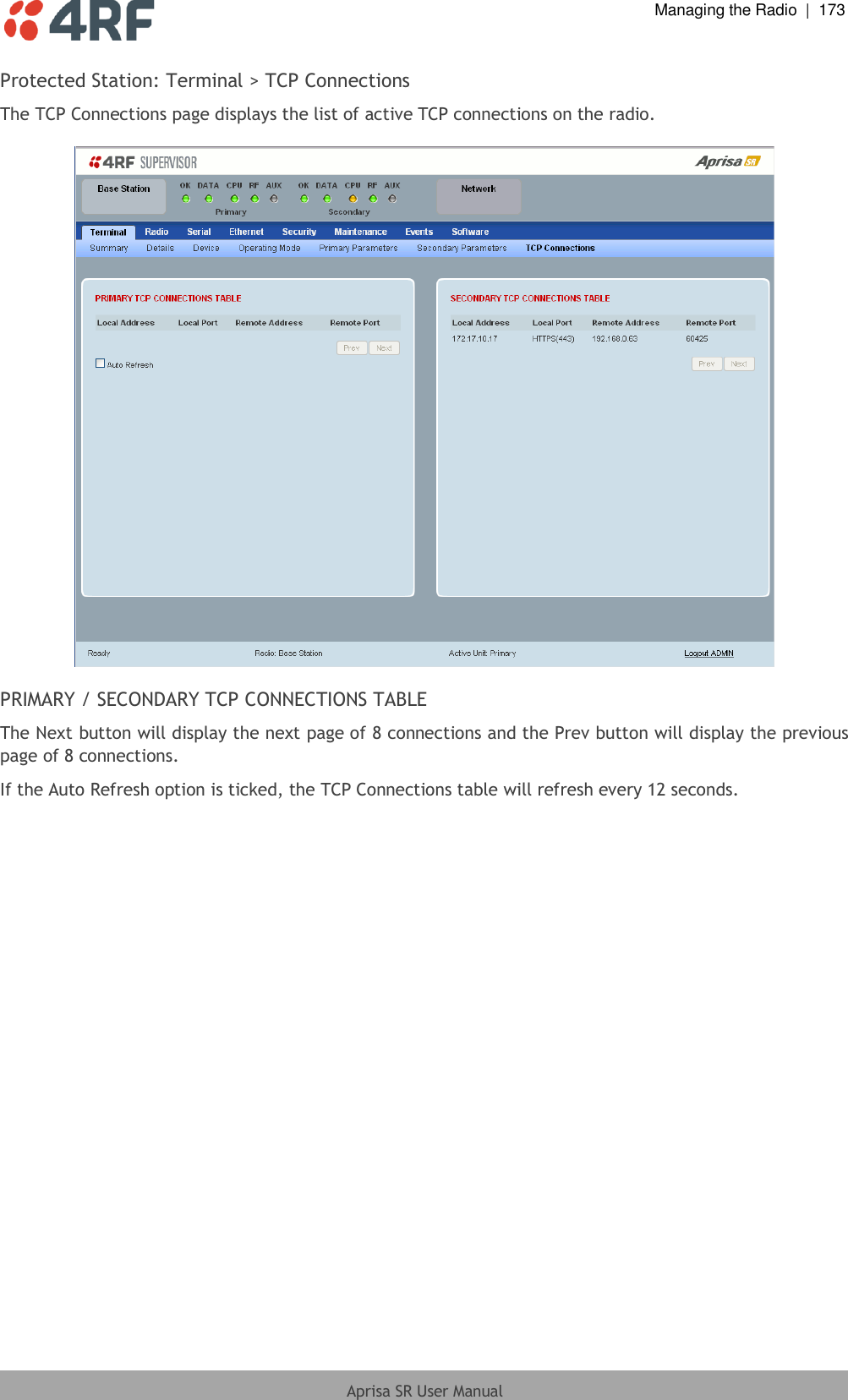
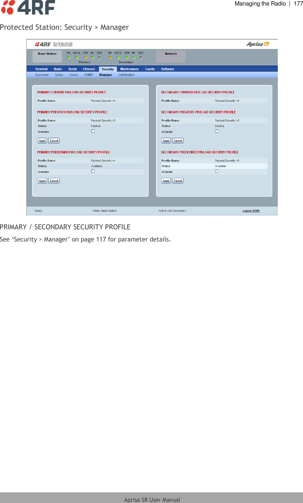
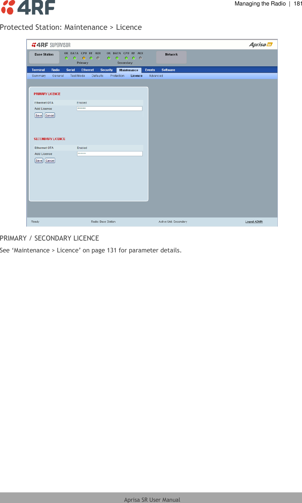
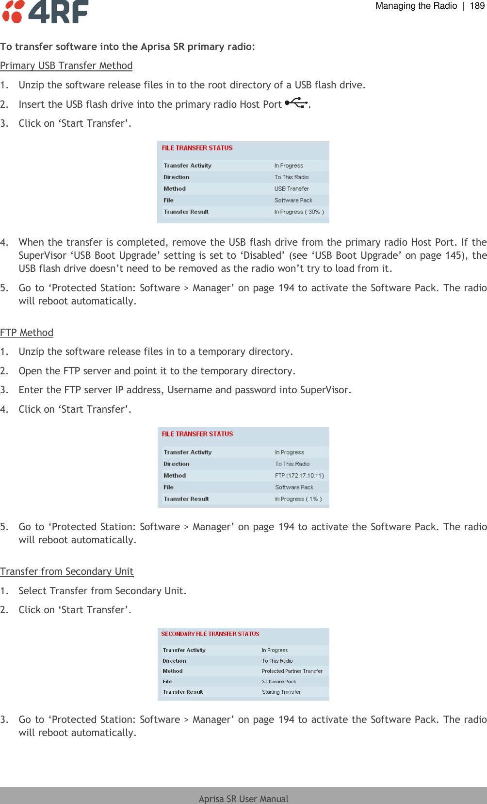
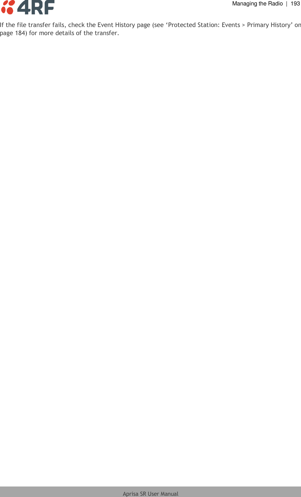
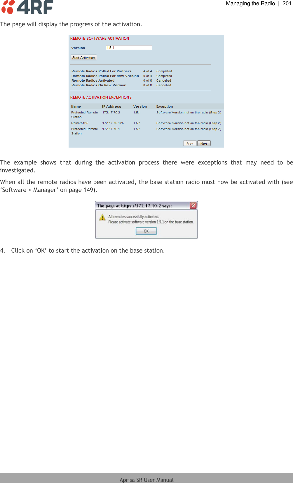
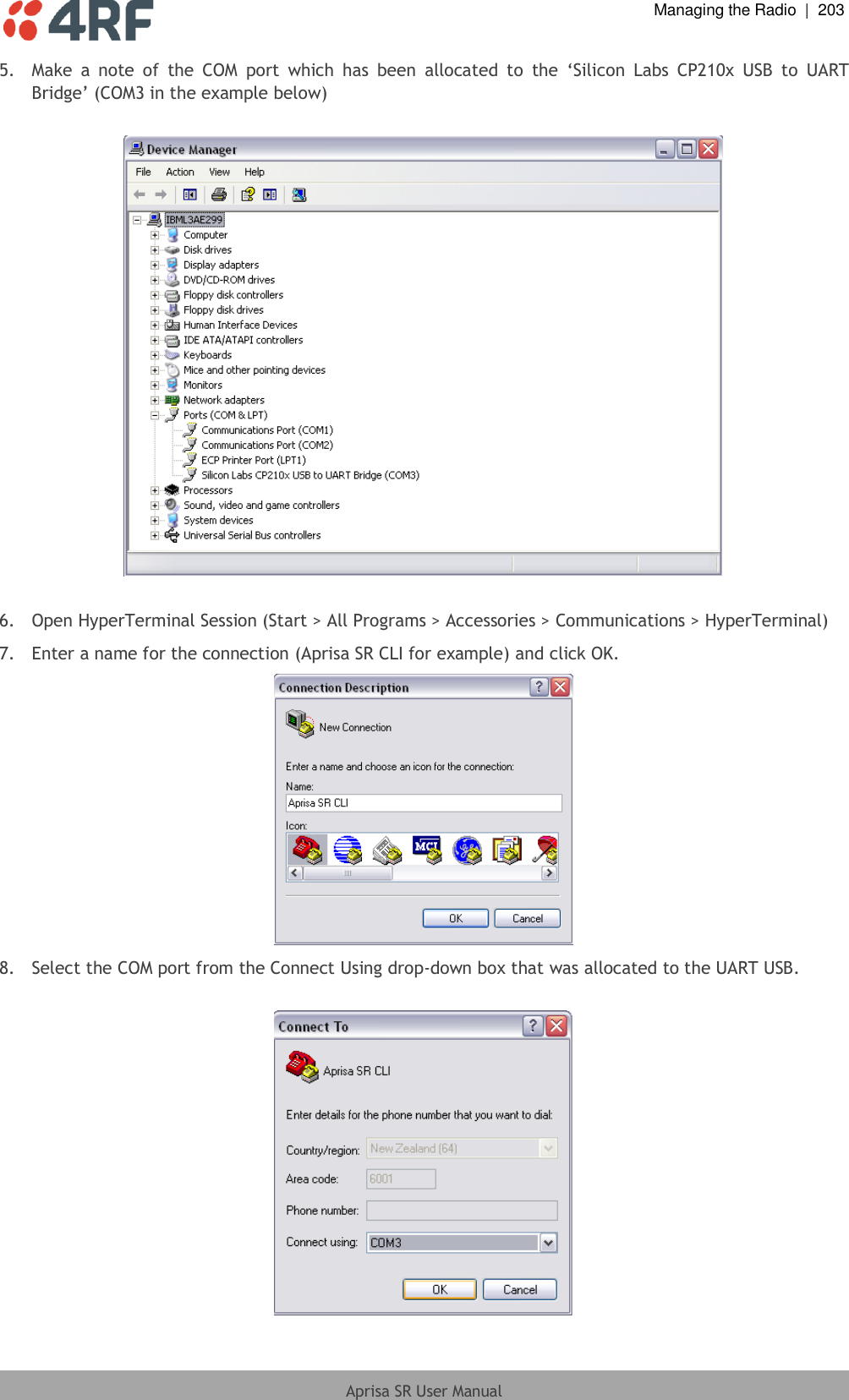
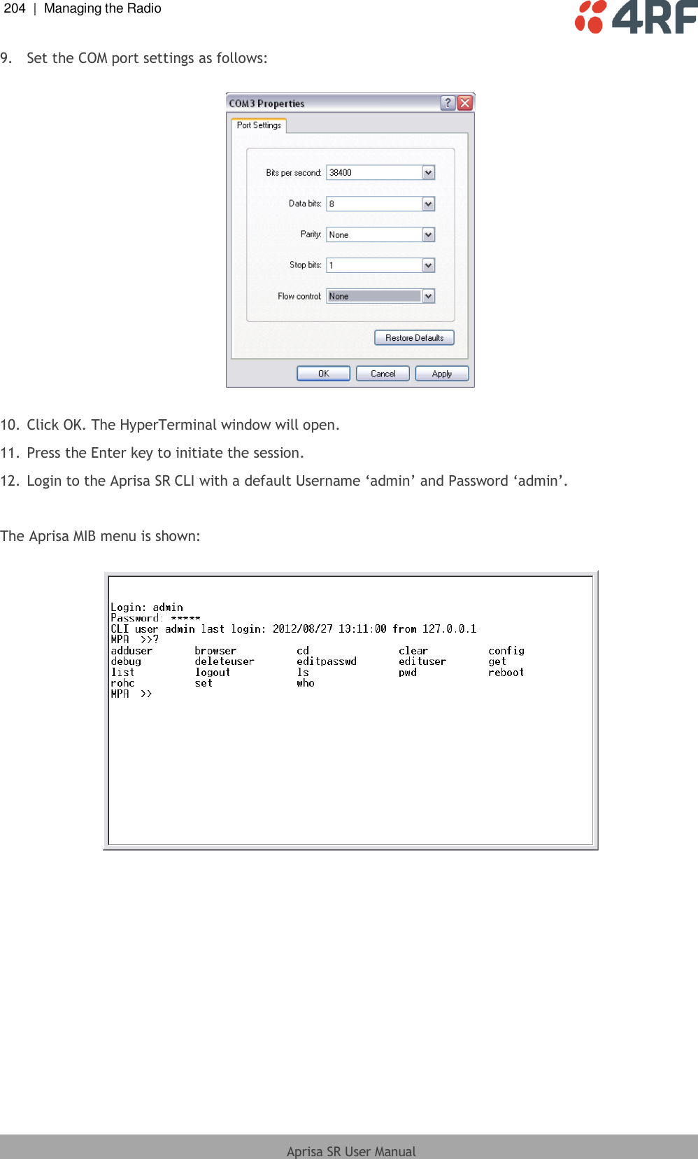
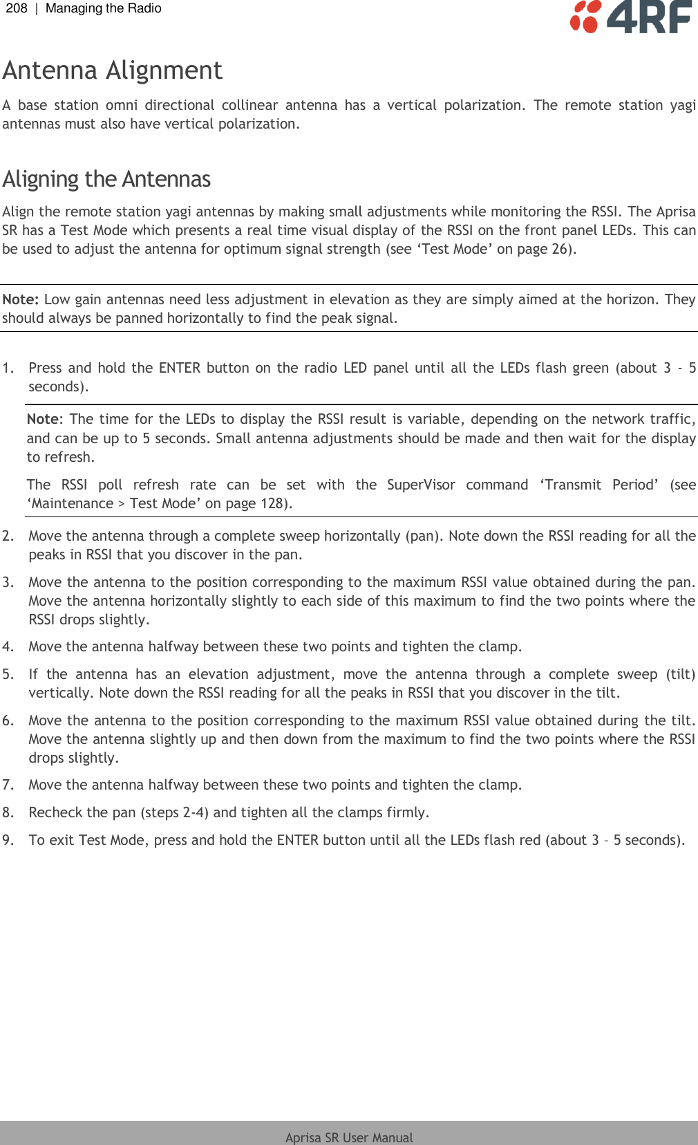
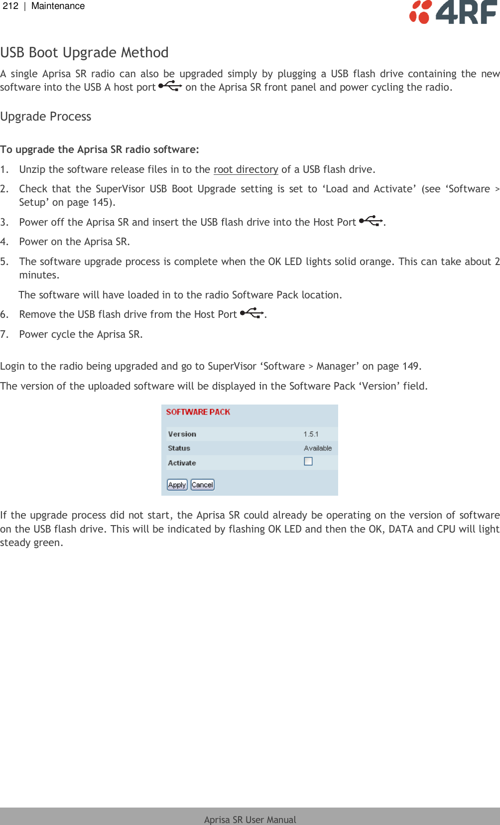
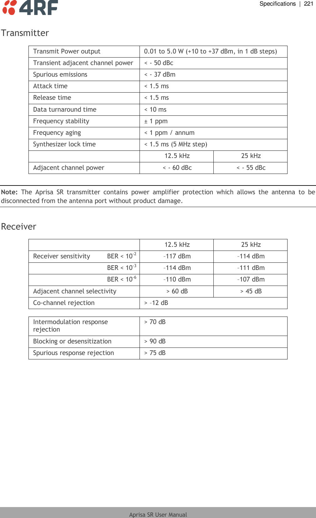
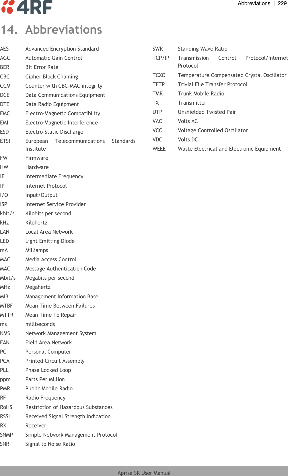
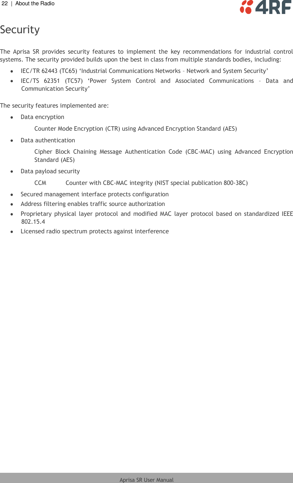
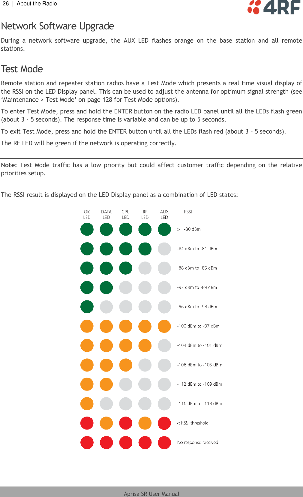
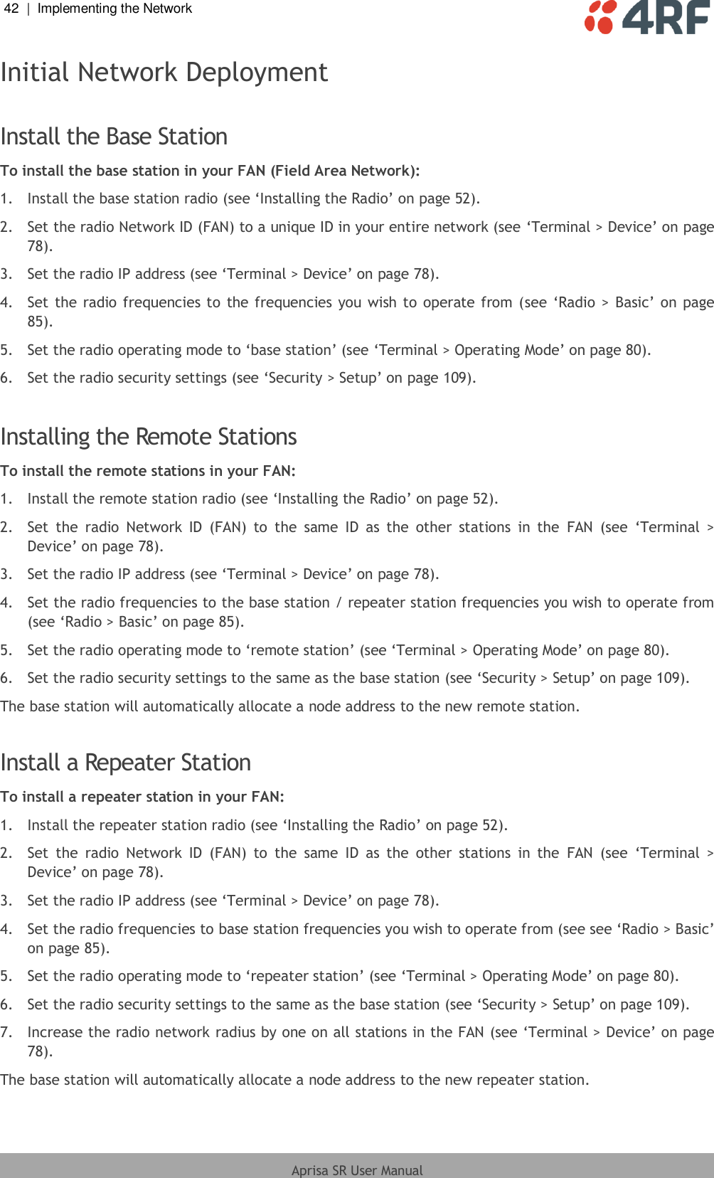
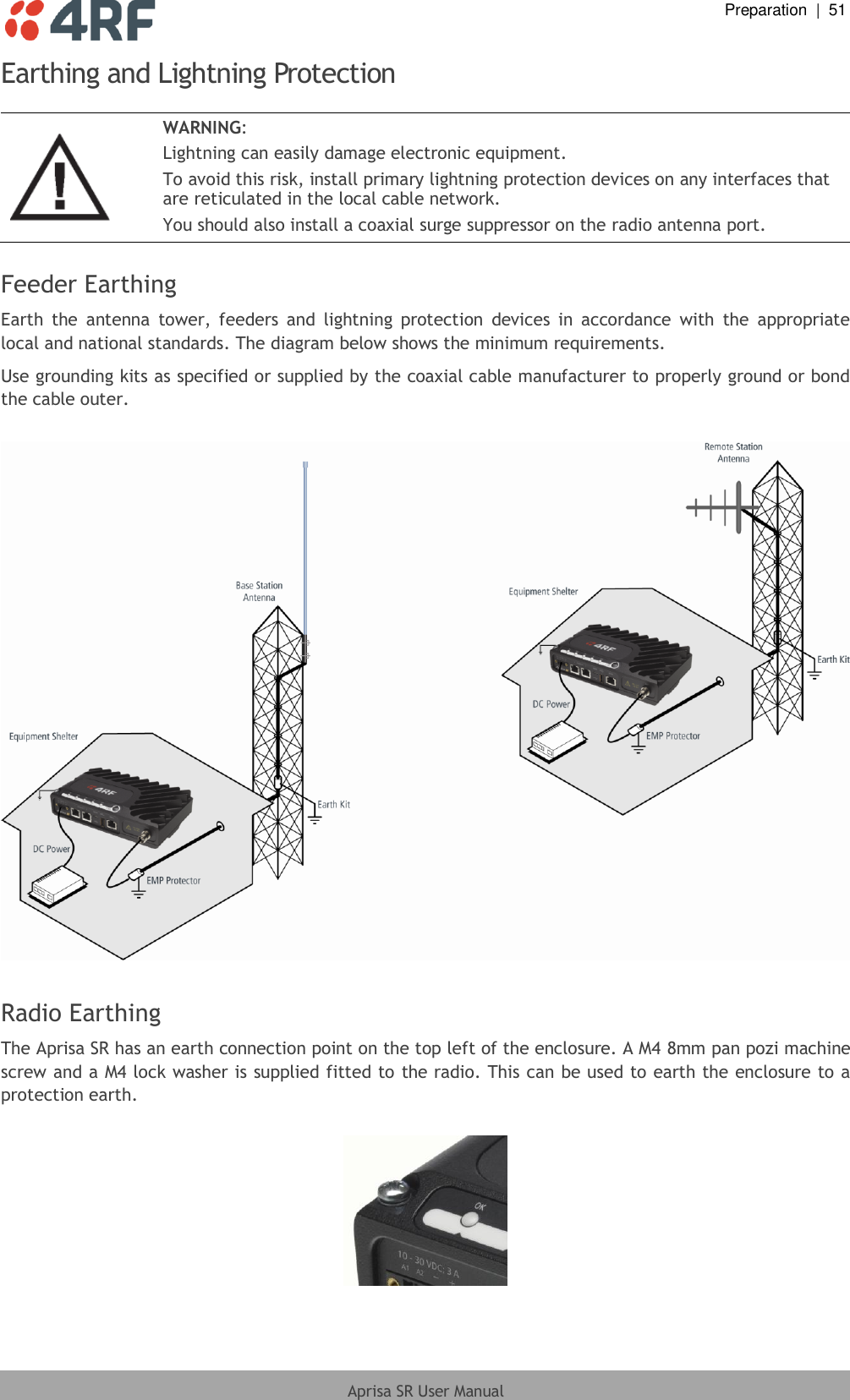
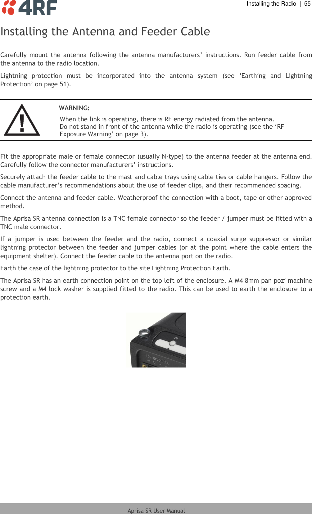
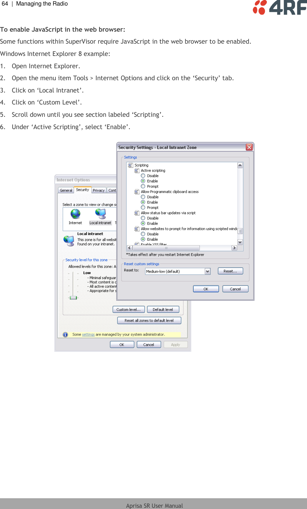
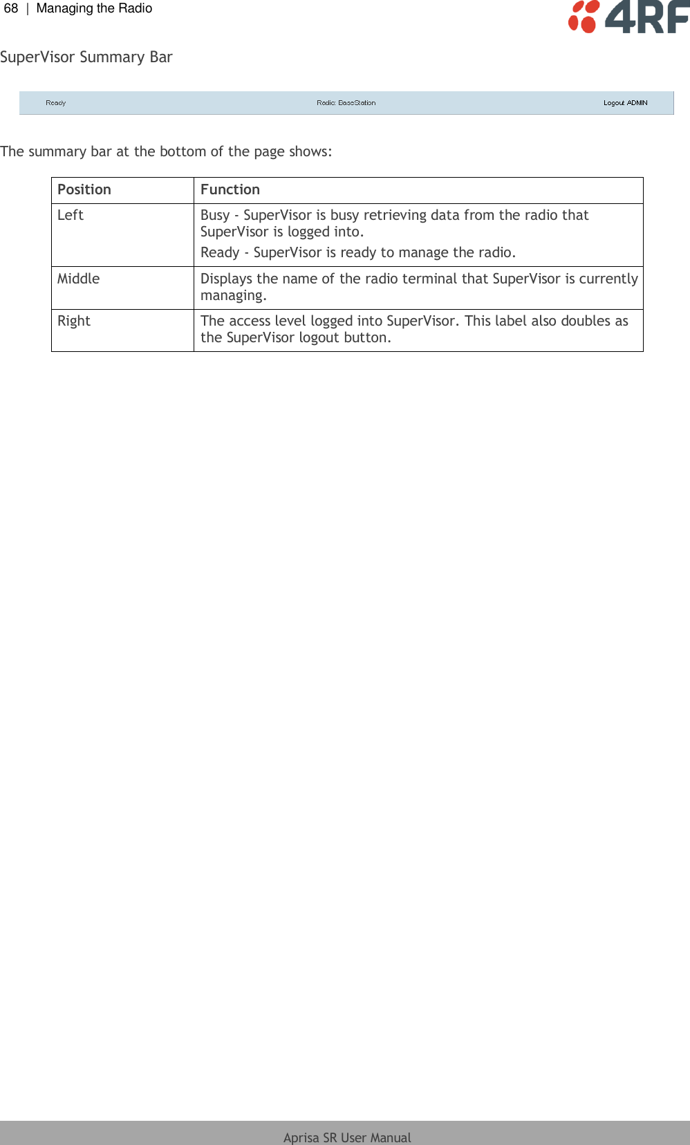
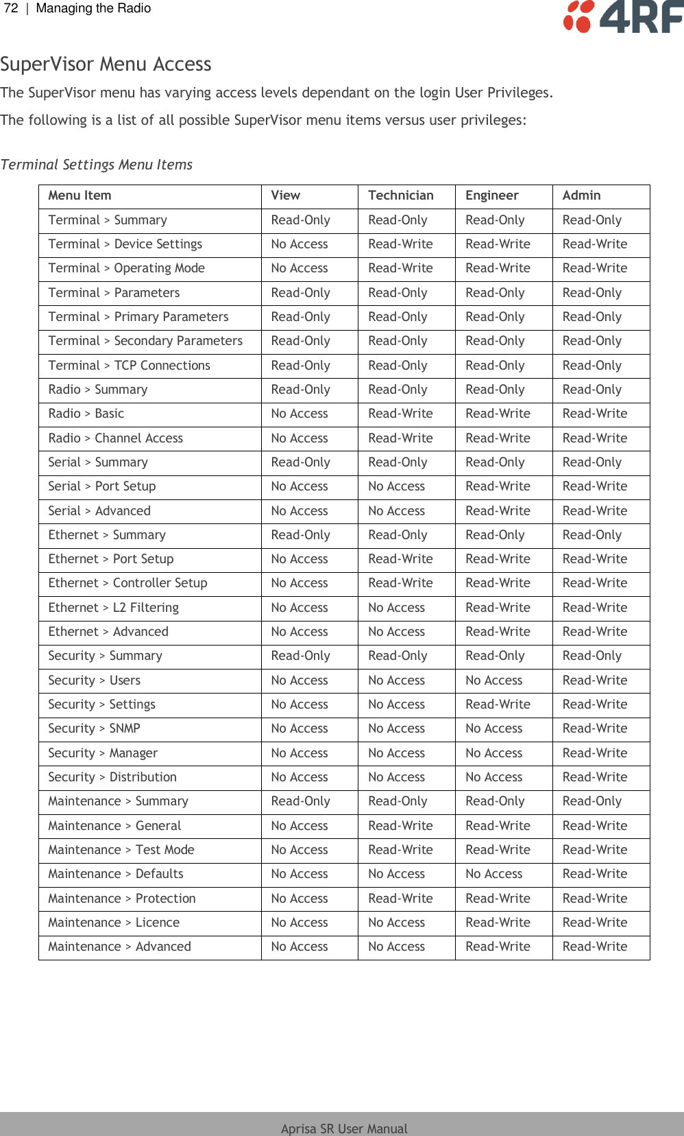
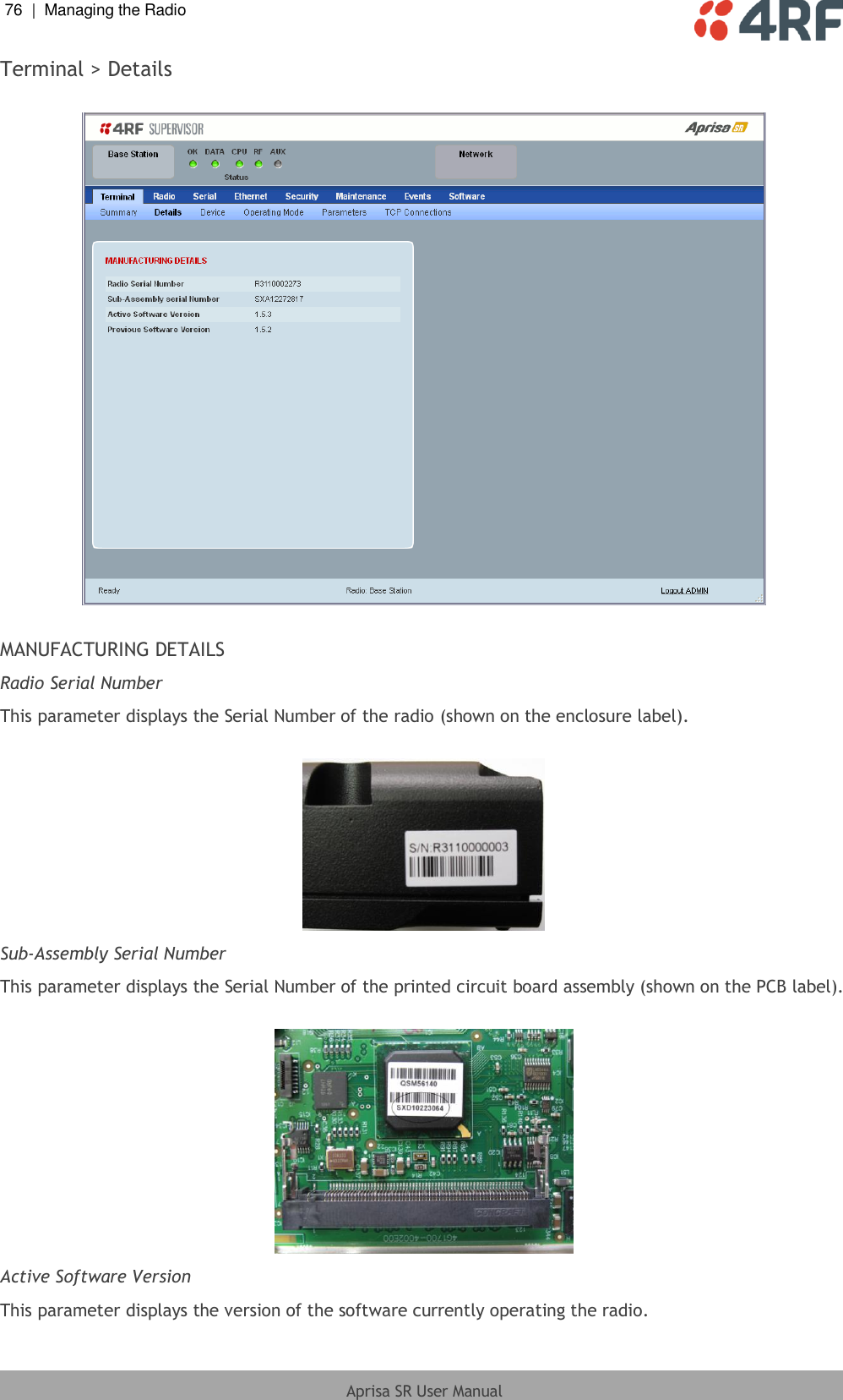
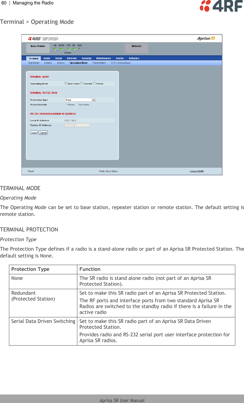
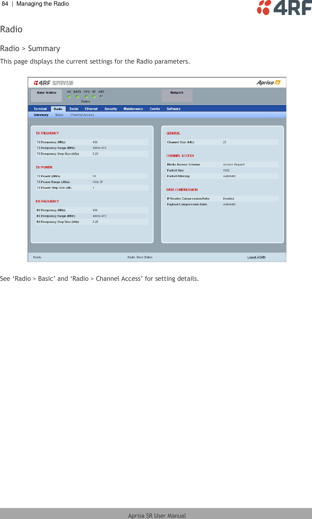
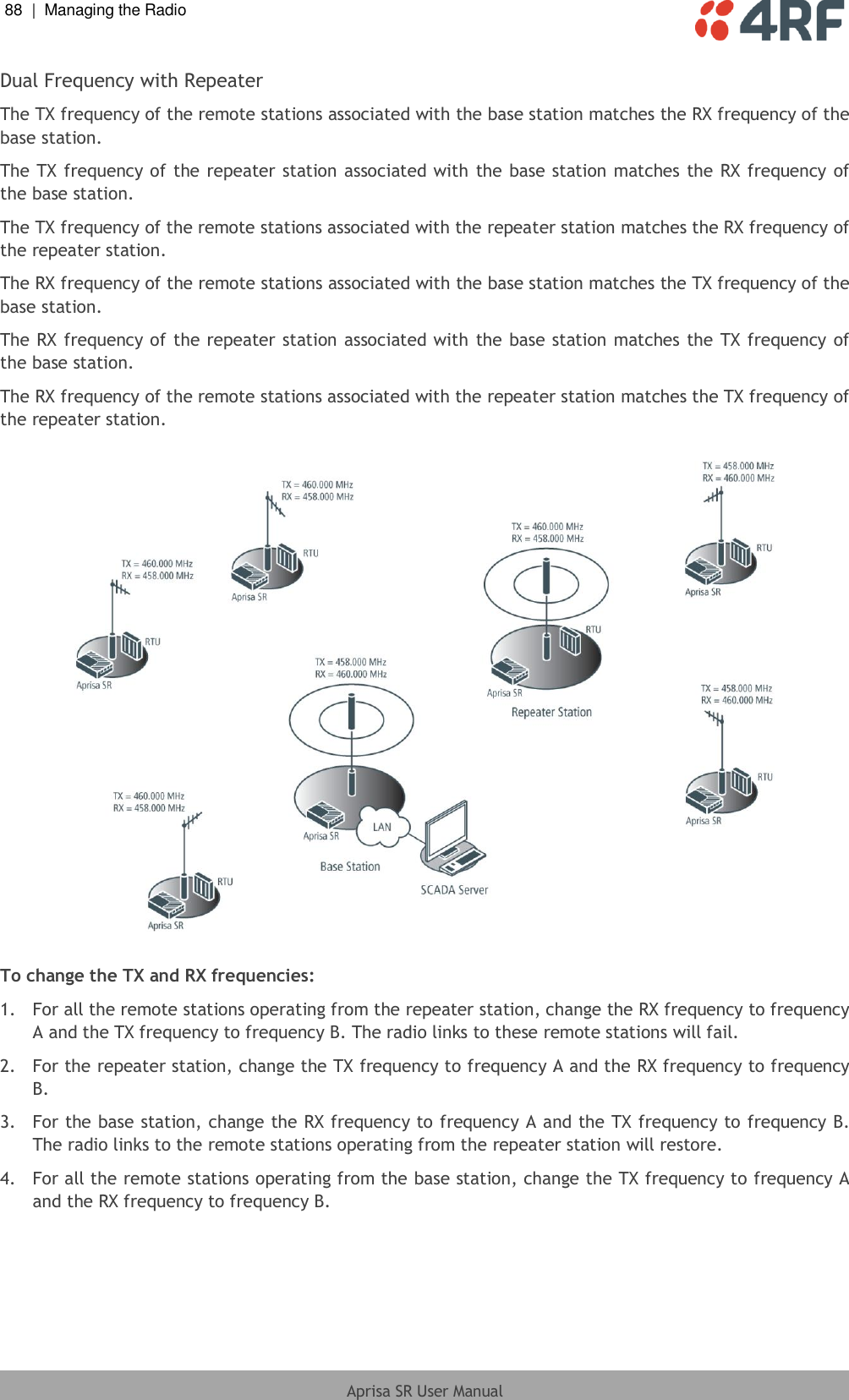
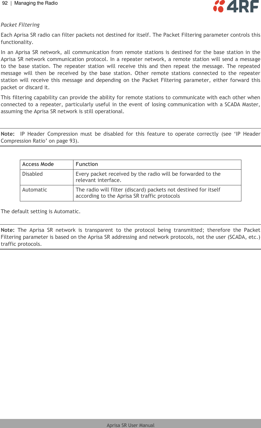
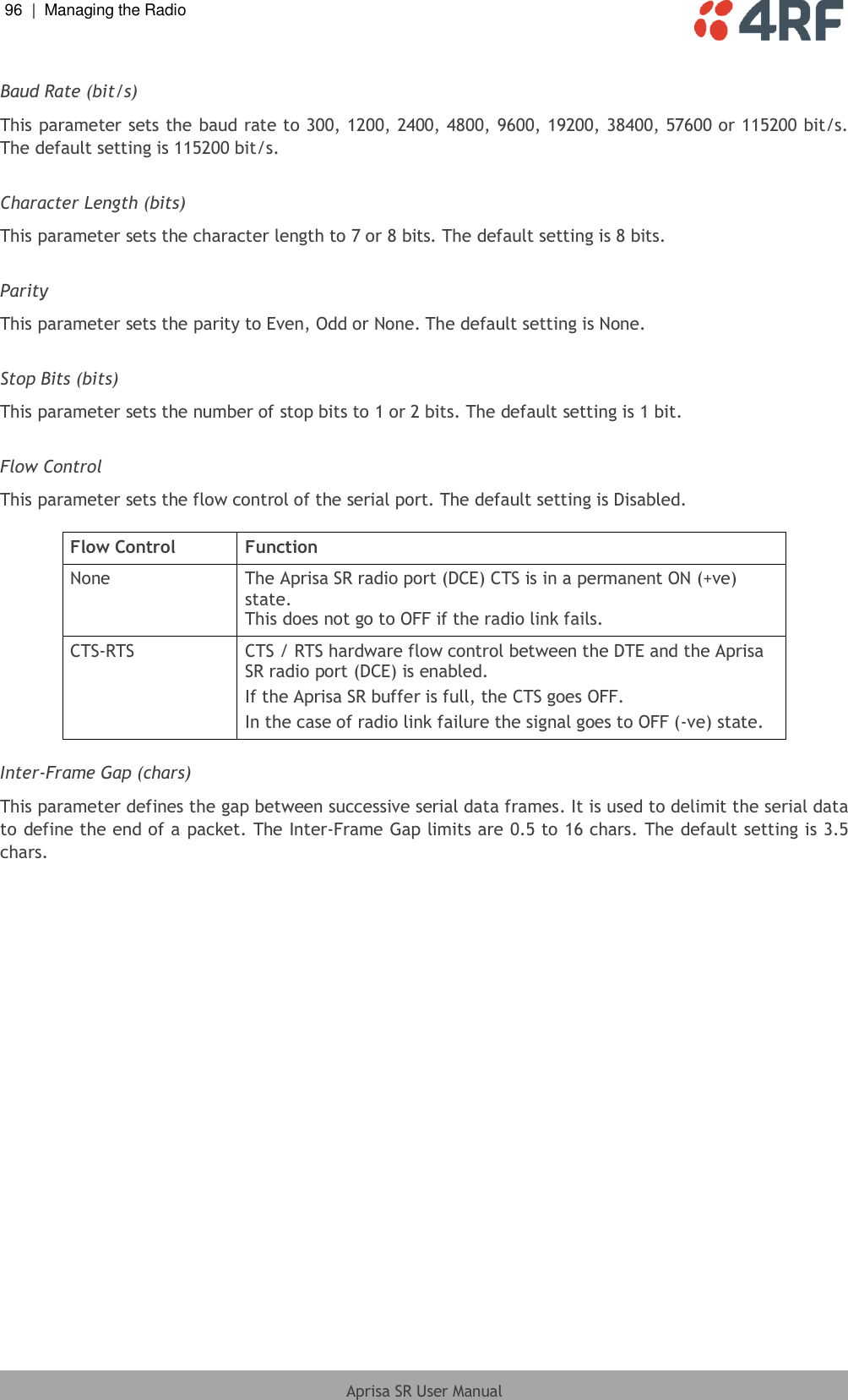
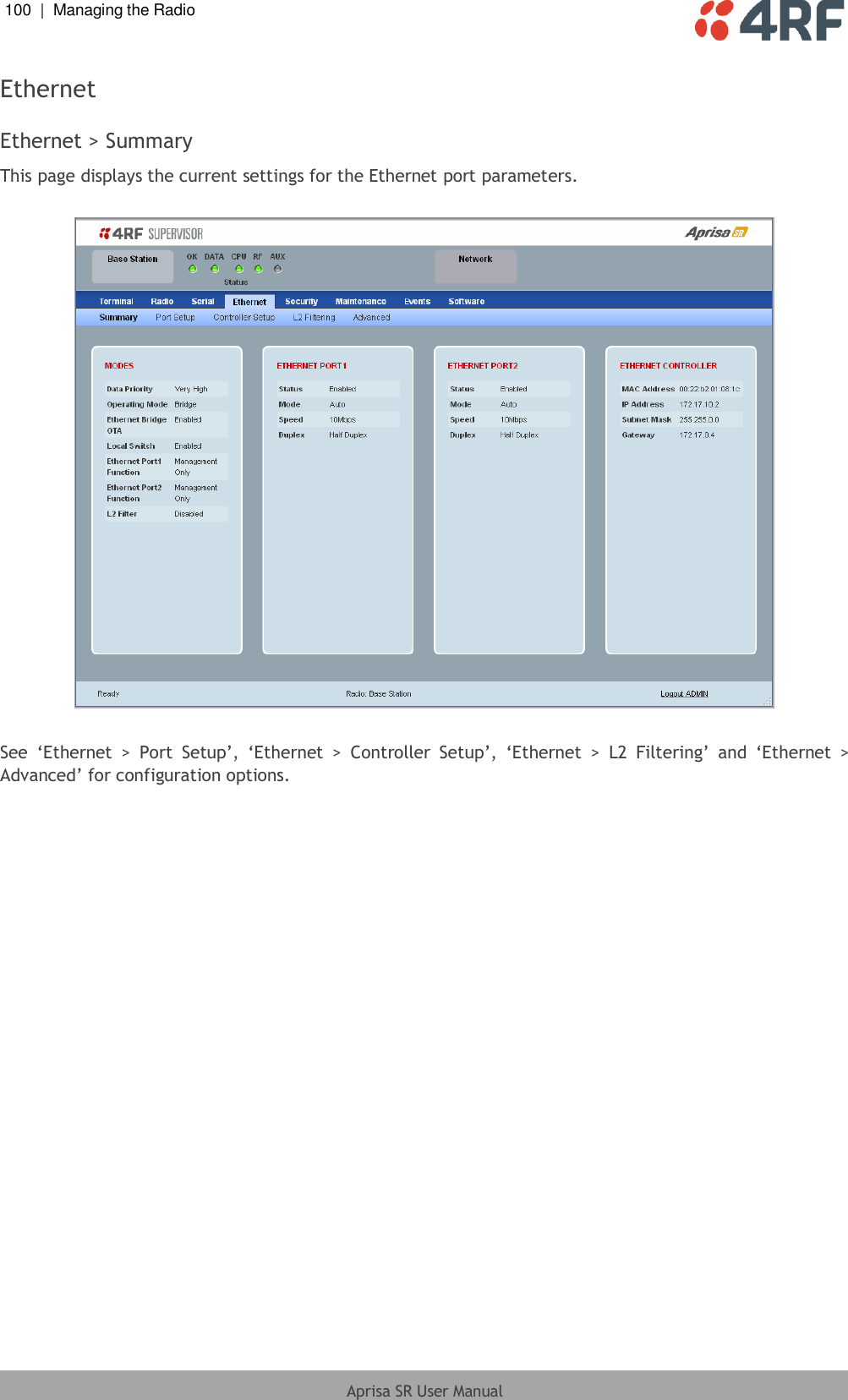
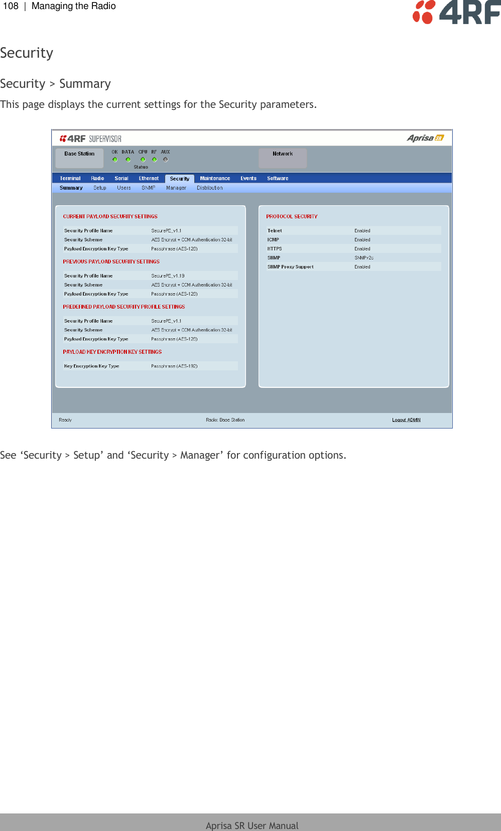
![Managing the Radio | 205 Aprisa SR User Manual CLI Commands To enter a CLI command: 1. Type the first few characters of the command and hit Tab. This auto completes the command. 2. Enter the command string and enter. Note: All CLI commands are case sensitive. The top level CLI command list is displayed by typing a ? at the command prompt. The following is a list of the top level CLI commands and their usage: CLI Command Usage adduser adduser [-g <password aging>] [-a <account aging>] [-i <role>] <userName> <userPassword> browser browser <state(STR)> cd cd <changeMode(STR)> clear Clears the screen config config userdefault save restore factorydefault restore debug set subsystem param(INT) level param(INT) get clear subsystem param(INT) level param(INT) help log dump clear deleteuser deleteuser <userName> editpasswd editpasswd <oldpassword> <newpassword> edituser edituser [-p <password>] [-g <password aging>] [-a <account aging>] [-i] get get [-m <mib name>] [-n <module name>] <attribute name> [indexes] list list <tablename> logout Logs out from the CLI ls Displays the next level menu items pwd Displays the current working directory reboot Reboots the radio rohc stats show clear set set [-m <mib name> ] [-n <module name>] <attribute name> <attribute set v] who Shows the users currently logged into the radio](https://usermanual.wiki/4RF/SRN0400025A/User-Guide-2013875-Page-207.png)