4RF XE20001300 Aprisa XE 2G0-500-vv User Manual Part 90
4RF Limited Aprisa XE 2G0-500-vv Part 90
4RF >
User Manual Revised

April 2012
Version 8.6.77

| 1
Aprisa XE User Manual
Copyright
Copyright © 2012 4RF Limited. All rights reserved.
This document is protected by copyright belonging to 4RF Limited and may not be reproduced or
republished in whole or part in any form without the prior written permission of 4RF Limited.
Trademarks
Aprisa and the 4RF logo are trademarks of 4RF Limited.
Windows is a registered trademark of Microsoft Corporation in the United States and other countries. Java
and all Java-related trademarks are trademarks or registered trademarks of Sun Microsystems, Inc. in the
United States and other countries. All other marks are the property of their respective owners.
GoAhead WebServer. Copyright © 2000 GoAhead Software, Inc. All Rights Reserved.
Disclaimer
Although every precaution has been taken preparing this information, 4RF Limited assumes no liability for
errors and omissions, or any damages resulting from use of this information. This document or the
equipment may change, without notice, in the interests of improving the product.
RoHS and WEEE Compliance
The Aprisa XE is fully compliant with the European Commission’s RoHS (Restriction of Certain Hazardous
Substances in Electrical and Electronic Equipment) and WEEE (Waste Electrical and Electronic Equipment)
environmental directives.
Restriction of hazardous substances (RoHS)
The RoHS Directive prohibits the sale in the European Union of electronic equipment containing these
hazardous substances: lead*, cadmium, mercury, hexavalent chromium, polybrominated biphenyls (PBBs),
and polybrominated diphenyl ethers (PBDEs).
4RF Limited has worked with its component suppliers to ensure compliance with the RoHS Directive which
came into effect on the 1st July 2006.
*The European Commission Technical Adaptation Committee (TAC) has exempted lead in solder for high-
reliability applications for which viable lead-free alternatives have not yet been identified. The exemption
covers communications network infrastructure equipment, which includes 4RF Limited Aprisa XE
microwave radios.
End-of-life recycling programme (WEEE)
The WEEE Directive concerns the recovery, reuse, and recycling of electronic and electrical equipment.
Under the Directive, used equipment must be marked, collected separately, and disposed of properly.
4RF Limited has instigated a programme to manage the reuse, recycling, and recovery of waste in an
environmentally safe manner using processes that comply with the WEEE Directive (EU Waste Electrical
and Electronic Equipment 2002/96/EC).
4RF Limited invites questions from customers and partners on its environmental programmes and
compliance with the European Commission’s Directives (sales@4RF.com).
2 |
Aprisa XE User Manual
Compliance General
The Aprisa XE digital radio predominantly operates within frequency bands that require a site license be
issued by the radio regulatory authority with jurisdiction over the territory in which the equipment is
being operated.
It is the responsibility of the user, before operating the equipment, to ensure that where required the
appropriate license has been granted and all conditions attendant to that license have been met.
Changes or modifications not approved by the party responsible for compliance could void the user’s
authority to operate the equipment.
Equipment authorizations sought by 4RF Limited are based on the Aprisa XE radio equipment being
installed at a fixed location and operated in a continuous point-to-point mode within the environmental
profile defined by EN 300 019, Class 3.2. Operation outside these criteria may invalidate the
authorizations and / or license conditions.
The term ‘Terminal’ with reference to the Aprisa XE User Manual, is a generic term for one end of a fixed
point-to-point Aprisa XE link and does not confer any rights to connect to any public network or to operate
the equipment within any territory.
Compliance ETSI
The Aprisa XE radio terminal is designed to comply with the European Telecommunications Standards
Institute (ETSI) specifications as follows:
Radio performance
EN 302 217 Parts 1, 2.1, and 2.2
EMC
EN 301 489 Parts 1 & 4
Environmental
EN 300 019, Class 3.2
Safety
EN 60950
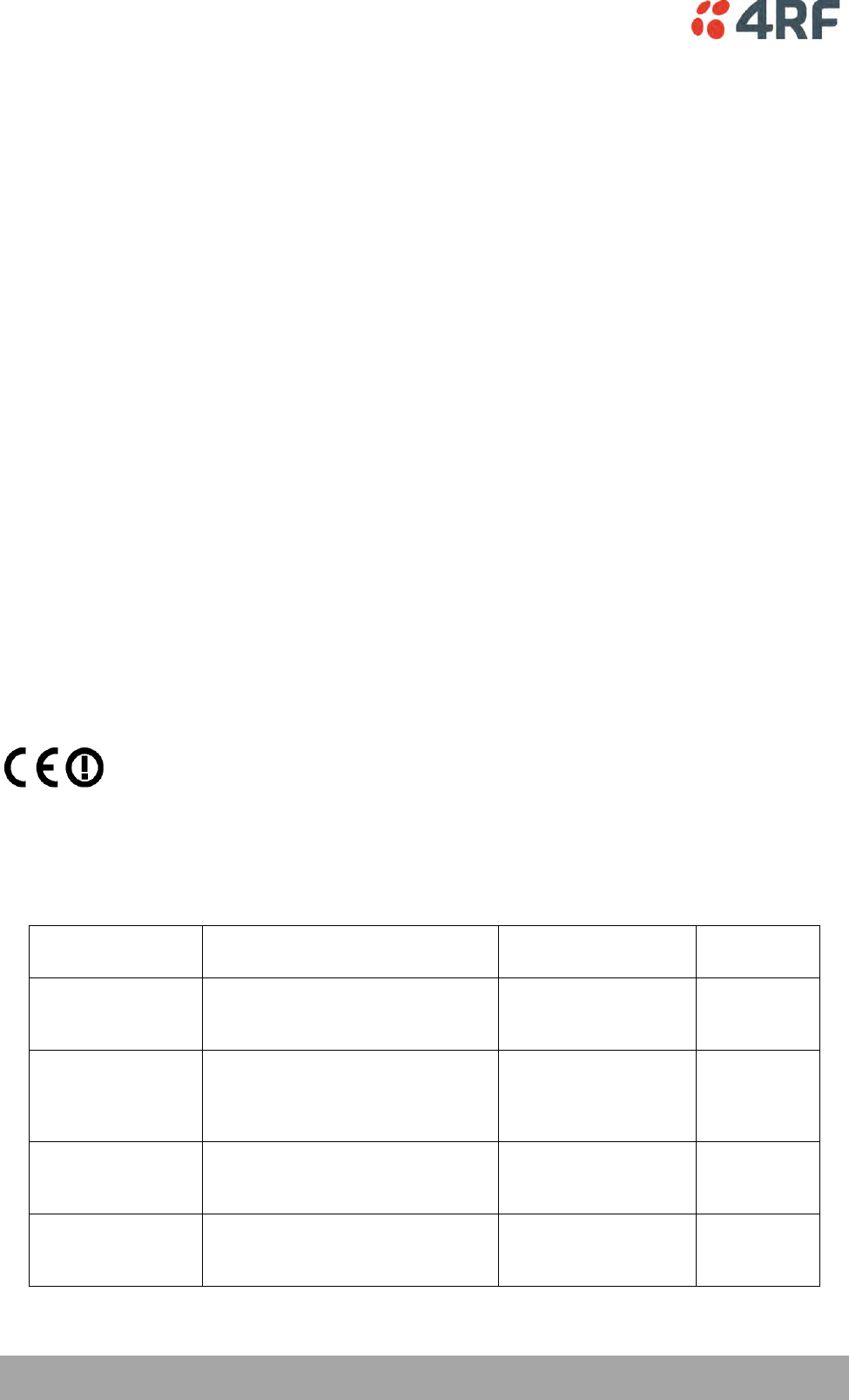
An Aprisa XE radio terminal operating in the following frequency bands / channel sizes
has been tested and is compliant to the ETSI radio specifications and suitably displays
the CE logo.
Other bands are compliant to the same radio performance specifications as adapted by
4RF Limited and therefore may be used in regions where compliance requirements
demand CE performance at other frequencies.
Frequency band
Channel size
Power input
Notified
body
300 MHz
400 MHz
25 kHz, 50 kHz, 75 kHz, 125 kHz,
150 kHz, 250 kHz, 500 kHz,
1.0 MHz, 1.75 MHz, 3.50 MHz
12 VDC, 24 VDC,
48 VDC, 115/230 VAC
Notified
Body 0678
600 MHz
700 MHz
800 MHz
900 MHz
500 kHz
12 VDC, 24 VDC,
48 VDC, 115/230 VAC
Notified
Body 0678
1400 MHz
75 kHz, 150 kHz, 250 kHz,
500 kHz, 1.0 MHz, 1.75 MHz,
3.50 MHz, 7 MHz
12 VDC, 12 VDC LP,
24 VDC, 48 VDC,
115/230 VAC
1800 MHz
2000 MHz
2500 MHz
250 kHz, 500 kHz, 1.0 MHz,
1.75 MHz, 3.50 MHz, 7 MHz,
14 MHz
12 VDC, 24 VDC,
48 VDC, 115/230 VAC

| 3
Aprisa XE User Manual
Informal Declaration of Conformity
Dansk
Undertegnede 4RF Limited erklærer herved, at følgende udstyr Aprisa Radio
overholder de væsentlige krav og øvrige relevante krav i direktiv 1999/5/EF.
Deutsch
Hiermit erklärt 4RF Limited, dass sich dieses Aprisa Radio in Übereinstimmung
mit den grundlegenden Anforderungen und den anderen relevanten
Vorschriften der Richtlinie 1999/5/EG befindet. (BMWi)
Dutch
Hierbij verklaart 4RF Limited dat het toestel Aprisa Radio in
overeenstemming is met de essentiële eisen en de andere relevante
bepalingen van richtlijn 1999/5/EG.
English
Hereby, 4RF Limited, declares that this Aprisa Radio equipment is in
compliance with the essential requirements and other relevant provisions of
Directive 1999/5/EC.
Español
Por medio de la presente 4RF Limited declara que el Aprisa Radio cumple con
los requisitos esenciales y cualesquiera otras disposiciones aplicables o
exigibles de la Directiva 1999/5/CE.
λληνας
ΜΕ ΣΗΝ ΠΑΡΟΤΑ 4RF Limited ΔΗΛΩΝΕΙ ΟΣΙ Aprisa Radio ΤΜΜΟΡΥΩΝΣΑΙ
ΠΡΟ ΣΙ ΟΤΙΩΔΕΙ ΑΠΑΙΣΗΕΙ ΚΑΙ ΣΙ ΔΟΙΠΕ ΦΕΣΙΚΕ ΔΙΑΣΑΞΕΙ ΣΗ
ΟΣΗΓΙΑ 1995/5/ΚΕ.
Français
Par la présente 4RF Limited déclare que l'appareil Aprisa Radio est conformé
aux exigences essentielles et aux autres dispositions pertinentes de la
directive 1999/5/CE.
Italiano
Con la presente 4RF Limited dichiara che questo Aprisa Radio è conforme ai
requisiti essenziali ed alle altre disposizioni pertinenti stabilite dalla direttiva
1999/5/CE.
Português
4RF Limited declara que este Aprisa Radio está conforme com os requisitos
essenciais e outras provisões da Directiva 1999/5/CE.
Suomalainen
4RF Limited vakuuttaa täten että Aprisa Radio tyyppinen laite on direktiivin
1999/5/EY oleellisten vaatimusten ja sitä koskevien direktiivin muiden
ehtojen mukainen.
Svensk
Härmed intygar 4RF Limited att denna Aprisa Radio står I överensstämmelse
med de väsentliga egenskapskrav och övriga relevanta bestämmelser som
framgår av direktiv 1999/5/EG.
A formal Declaration of Conformity document is shipped with each Aprisa XE terminal.
4 |
Aprisa XE User Manual
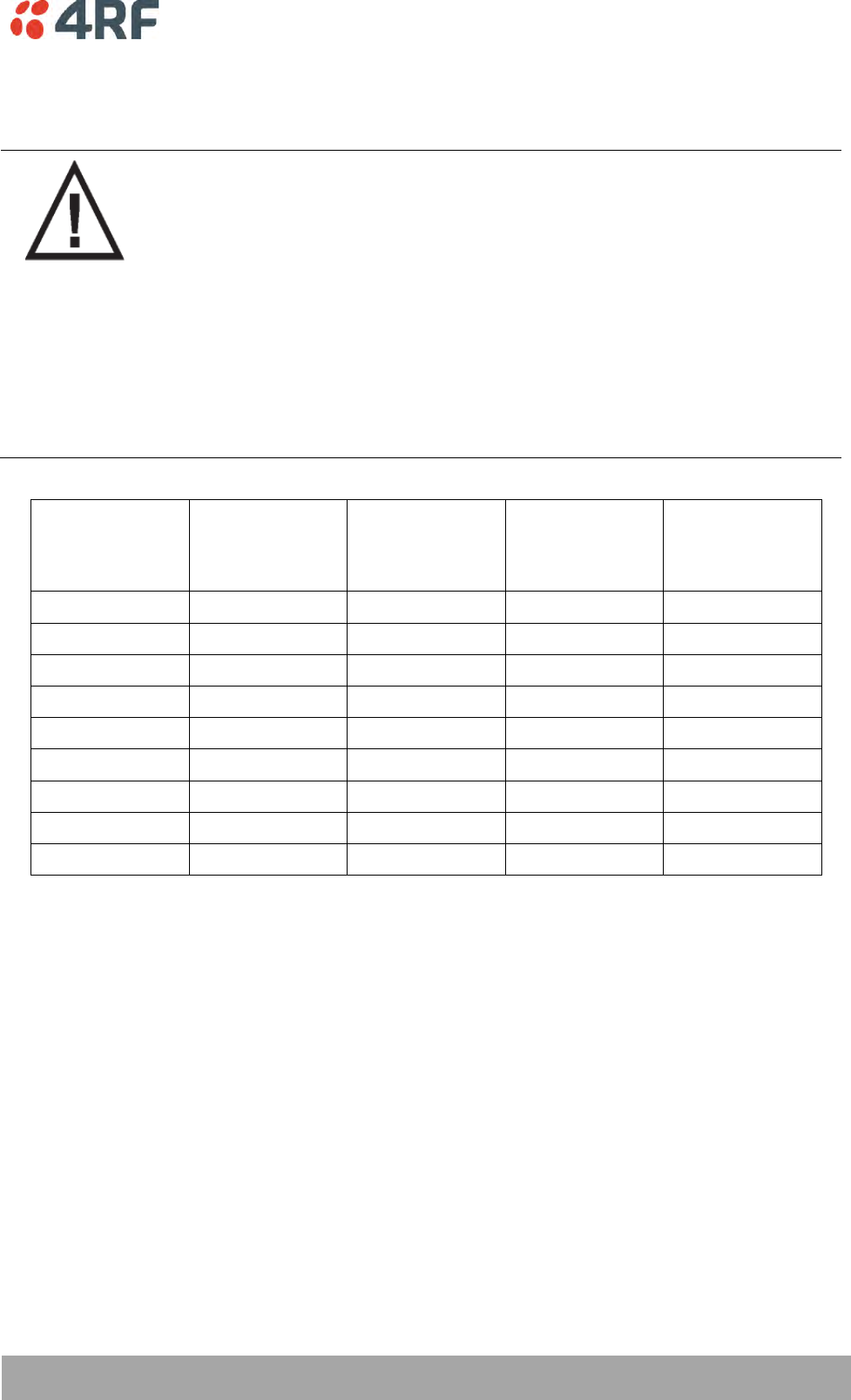
Compliance Federal Communications Commission
The Aprisa XE radio terminal is designed to comply with the Federal Communications Commission (FCC)
specifications as follows:
Radio performance / EMC
(dependant on variant)
47CFR part 90 Private Land Mobile Radio Services
47CFR part 101 Fixed Microwave Services
47CFR part 27 Misc Wireless Communication Services
47CFR part 15 Radio Frequency Devices
Safety
EN 60950
Frequency band
limits
Channel
size
Power input
Authorization
FCC ID
421 MHz to
512 MHz
25 kHz
48 VDC
Part 90 Certification
UIPN0400025A0200A
932.5 MHz to
944 MHz
100 kHz,
200 kHz
24 VDC,
48 VDC,
110 VAC
Part 101 Verification
-
2314.5 MHz to
2317.5 MHz
2346.5 MHz to
2349.5 MHz
250 kHz,
500 kHz
24 VDC,
48 VDC,
110 VAC
Part 27 Certification
UIPN2500AAAA0200A
2180 MHz to
2290 MHz
500 kHz
110 VAC
Part 101 Certification
UIPXE20001300
NOTE: This equipment has been tested and found to comply with the limits for a Class A digital device,
pursuant to part 15 of the FCC Rules. These limits are designed to provide reasonable protection against
harmful interference when the equipment is operated in a commercial environment. This equipment
generates, uses, and can radiate radio frequency energy and, if not installed and used in accordance with
the instruction manual, may cause harmful interference to radio communications. Operation of this
equipment in a residential area is likely to cause harmful interference in which case the user will be
required to correct the interference at his own expense.
| 5
Aprisa XE User Manual
RF Exposure Warning
WARNING:
The installer and / or user of Aprisa XE radio terminals shall ensure that a separation
distance as given in the following table is maintained between the main axis of the
terminal’s antenna and the body of the user or nearby persons.
Minimum separation distances given are based on the maximum values of the
following methodologies:
1. Maximum Permissible Exposure non-occupational limit (B or general public) of
47 CFR 1.1310 and the methodology of FCC’s OST/OET Bulletin number 65.
2. Reference levels as given in Annex III, European Directive on the limitation of
exposure of the general public to electromagnetic fields (0 Hz to 300 GHz)
(1999/519/EC). These distances will ensure indirect compliance with the
requirements of EN 50385:2002.
Frequency
(MHz)
Maximum power
(dBm)
Maximum
antenna gain
(dBi)
Maximum power
density
(mW/cm2)
Minimum
separation
distance
(m)
400
+ 35
15
0.20
2.0
512
+ 35
15
0.26
1.8
715
+ 34
15
0.36
1.3
806
+ 34
28
0.40
5.6
890
+ 34
28
0.45
5.3
960
+ 34
28
0.48
5.1
1550
+ 34
33
0.78
7.2
2300
+ 34
37
1.00
10.0
2700
+ 34
38
1.00
11.2

Contents | 7
Aprisa XE User Manual
Contents
1. Getting Started .......................................................................... 15
2. Introduction .............................................................................. 19
About This Manual ............................................................................... 19
What It Covers ............................................................................ 19
Who Should Read It ...................................................................... 19
Contact Us ................................................................................. 19
What's in the Box ................................................................................ 19
Aprisa XE CD Contents ................................................................... 20
Accessory Kit .............................................................................. 21
3. Preparation............................................................................... 23
Path Planning .................................................................................... 23
Antenna Selection and Siting ........................................................... 23
Coaxial Feeder Cables ................................................................... 26
Link Budget ................................................................................ 26
Site Requirements ............................................................................... 27
Power Supply .............................................................................. 27
Equipment Cooling ....................................................................... 27
Earthing and Lightning Protection ..................................................... 28
4. About the Terminal..................................................................... 29
Introduction ...................................................................................... 29
Modules ........................................................................................... 30
Front Panel Connections and Indicators ..................................................... 31
Interface Card Types............................................................................ 32
5. Mounting and Installing the Terminal .............................................. 33
Required Tools ................................................................................... 33
Installing the Terminal ......................................................................... 33
Installing the Antenna and Feeder Cable .................................................... 34
External Alarms .................................................................................. 35
Alarm Circuit Setup ...................................................................... 35
Interface Cabling ................................................................................ 36
Power Supplies................................................................................... 37
DC Power Supply.......................................................................... 37
AC Power Supply .......................................................................... 40
Safety Earth ............................................................................... 42
Bench Setup ...................................................................................... 43

8 | Contents
Aprisa XE User Manual
6. Connecting to the Terminal .......................................................... 45
Connecting to the Terminal's Setup Port .................................................... 45
Connecting to the Terminal's Ethernet Interface ........................................... 48
PC Requirements for SuperVisor ....................................................... 49
PC Settings for SuperVisor .............................................................. 50
IP Addressing of Terminals ..................................................................... 53
Network IP Addressing .......................................................................... 54
Same Subnet as the Local PC ........................................................... 54
Different Subnet as the Local PC ...................................................... 55
7. Managing the Terminal ................................................................ 57
The Setup Menu ................................................................................. 57
SuperVisor ........................................................................................ 59
SuperVisor Logging In .................................................................... 60
SuperVisor Logging Out .................................................................. 61
SuperVisor Main Screen ......................................................................... 62
Changing the Terminal’s IP Address .......................................................... 64
Setting Up Users ................................................................................. 65
User groups ................................................................................ 65
Adding a User ............................................................................. 65
Disabling a User........................................................................... 66
Deleting a User ........................................................................... 66
Saving User Information ................................................................. 66
Changing Passwords ...................................................................... 67
Viewing User Session Details ............................................................ 67
8. Configuring the Terminal ............................................................. 69
Configuring the RF Settings .................................................................... 69
Modem Performance Settings........................................................... 72
Entering Basic Terminal Information ......................................................... 74
Configuring the IP Settings ..................................................................... 75
Setting the Terminal Clocking ................................................................. 76
Setting the Duplexer Parameters ............................................................. 79
Setting the RSSI Alarm Threshold ............................................................. 80
Configuring the External Alarms .............................................................. 81
Configuring the External Alarm Inputs ................................................ 81
Configuring the External Alarm Outputs .............................................. 83
Configuring SNMP Settings ..................................................................... 85
SNMP Access Controls .................................................................... 86
SNMP Trap Destinations ................................................................. 87
Viewing the SNMP Traps ................................................................. 88
Viewing the SNMP MIB Details .......................................................... 88
Saving the Terminal's Configuration .......................................................... 89

Contents | 9
Aprisa XE User Manual
9. Configuring the Traffic Interfaces .................................................. 91
Viewing a Summary of the Interfaces ........................................................ 91
Configuring the Traffic Interfaces ............................................................ 92
Ethernet Switch ................................................................................. 93
VLAN tagging .............................................................................. 93
Quality of Service ........................................................................ 96
Viewing the Status of the Ethernet Ports ........................................... 100
Resetting the Ethernet Settings ...................................................... 100
Ethernet Port Startup .................................................................. 101
QJET Port Settings ............................................................................ 102
Q4EM Port Settings ............................................................................ 104
Loop Interface Circuits ....................................................................... 107
DFXO / DFXS Loop Interface Circuits ................................................ 107
E1 CAS to DFXS Circuits ................................................................ 110
DFXS to DFXS Hotline Circuits ........................................................ 110
DFXS Port Settings ...................................................................... 112
DFXO Port Settings ..................................................................... 120
QV24 Serial Interface Card ................................................................... 128
QV24 Port Settings ..................................................................... 129
QV24S Port Settings .................................................................... 130
HSS Port Settings .............................................................................. 133
HSS Handshaking and Clocking Modes ...................................................... 135
HSS Handshaking and Control Line Function ....................................... 135
HSS Synchronous Clock Selection Modes ............................................ 138

10 | Contents
Aprisa XE User Manual
10. Cross Connections ..................................................................... 145
Embedded Cross Connect Switch............................................................ 145
Link Capacity Utilization .............................................................. 145
The Cross Connections Application ......................................................... 145
The Cross Connections System Requirements ...................................... 145
Installing the Cross Connections Application ....................................... 146
Opening the Cross Connections Application ........................................ 146
The Cross Connections Page .......................................................... 147
Setting the Terminal's IP Address .................................................... 149
Management and User Ethernet Capacity........................................... 150
Setting Card Types ..................................................................... 151
Getting Cross Connection Configuration from the Terminals .................... 151
Creating Cross Connections ........................................................... 152
Sending Cross Connection Configuration to the Terminals ....................... 155
Saving Cross Connection Configurations ............................................ 155
Using Existing Cross Connection Configurations ................................... 155
Printing the Cross Connection Configuration ....................................... 156
Deleting Cross Connections ........................................................... 157
Configuring the Traffic Cross Connections ................................................. 158
Compatible Interfaces ................................................................. 158
QJET Cross Connections ............................................................... 159
Selecting and Mapping Bits and Timeslots .......................................... 166
Q4EM Cross Connections ............................................................... 170
DFXS and DFXO Cross Connections ................................................... 171
QV24 Cross Connections ............................................................... 172
QV24S Cross Connections .............................................................. 173
HSS Cross Connections ................................................................. 174
Cross Connection Example ................................................................... 175
Symmetrical Connection Wizard ............................................................ 176
Starting the Cross Connections Wizard .............................................. 176
Cross Connections Wizard Navigation ............................................... 176
Setting the Cross Connections IP Address ........................................... 177
Setting the Cross Connections Bandwidth .......................................... 177
Cross Connections Card Selection .................................................... 178
Cross Connections Interface Configurations ........................................ 179
Symmetrical Connection Summary................................................... 180
Send Symmetrical Connection Configuration ....................................... 180
11. Protected Terminals .................................................................. 181
Monitored Hot Stand By (MHSB) ............................................................. 181
Tributary Switch Front Panel ......................................................... 182
RF Switch Front Panel ................................................................. 183
MHSB Cabling............................................................................ 185
MHSB Power Supply .................................................................... 185
Configuring the Radios for Protected Mode ........................................ 186
Hitless Space Diversity (HSD) ................................................................ 190
HSD Terminal Cabling .................................................................. 191
HSD Terminal IP Addresses ............................................................ 192

Contents | 11
Aprisa XE User Manual
12. In-Service Commissioning ............................................................ 197
Before You Start ............................................................................... 197
What You Will Need .................................................................... 197
Applying Power to the Terminals ........................................................... 198
Review the Link Configurations Using SuperVisor ........................................ 198
Antenna Alignment ............................................................................ 199
Checking the Antenna Polarization .................................................. 199
Visually Aligning Antennas ............................................................ 200
Accurately Aligning the Antennas .................................................... 201
Checking Performance ................................................................. 203
Checking the Receive Input Level .................................................... 203
Checking the Fade Margin ............................................................. 204
Checking the Long-Term BER ......................................................... 205
Bit Error Rate Tests .................................................................... 205
Additional Tests ........................................................................ 206
Checking the Link Performance ...................................................... 207
Viewing a Summary of the Link Performance ...................................... 208
Saving the History of the Link Performance ........................................ 209
13. Maintenance ............................................................................ 213
Routine Maintenance ......................................................................... 213
Terminal Upgrades ............................................................................ 214
Software Upgrade Process ............................................................ 215
Uploading the Root File System ...................................................... 216
Uploading the Motherboard Images .................................................. 216
Identifying the Correct TFTP Upgrade Type ........................................ 217
TFTP Upgrade Process Types ......................................................... 220
Uploading System Files ................................................................ 226
Viewing the Image Table .............................................................. 231
Changing the Status of an Image File................................................ 232
Rebooting the Terminal ...................................................................... 233
Support Summary.............................................................................. 234
Installing Interface Cards .................................................................... 235
Preparing the Terminal for New Interface Cards .................................. 236
Installing an Interface Card ........................................................... 238
Configuring a Slot ...................................................................... 240
14. Troubleshooting ........................................................................ 241
Loopbacks ...................................................................................... 241
RF Radio Loopback ..................................................................... 241
Interface Loopbacks ................................................................... 242
Timeslot Loopbacks .................................................................... 243
Alarms........................................................................................... 244
Diagnosing Alarms ...................................................................... 244
Viewing the Alarm History ............................................................ 246
Saving the Alarm History .............................................................. 247
Viewing Interface Alarms.............................................................. 248
Clearing Alarms ......................................................................... 249
Identifying Causes of Alarms .......................................................... 250
E1 / T1 Alarm Conditions.............................................................. 252
System Log ..................................................................................... 253
Checking the Syslog .................................................................... 253
Setting up for Remote Logging ....................................................... 255

12 | Contents
Aprisa XE User Manual
15. Interface Connections ................................................................ 257
RJ-45 Connector Pin Assignments ........................................................... 257
Interface Traffic Direction ................................................................... 257
QJET Interface Connections ................................................................. 258
Ethernet Interface Connections ............................................................. 259
Q4EM Interface Connections ................................................................. 260
E&M Signalling Types .................................................................. 261
DFXS Interface Connections.................................................................. 263
DFXO Interface Connections ................................................................. 264
HSS Interface Connections ................................................................... 265
Synchronous cable assemblies ........................................................ 266
Cable WAN Connectors ................................................................ 272
QV24 Interface connections ................................................................. 273
QV24S Interface connections ................................................................ 273
16. Alarm Types and Sources ............................................................ 275
Alarm Types .................................................................................... 275
Transmitter Alarms..................................................................... 275
Receiver Alarms ........................................................................ 277
MUX Alarms .............................................................................. 280
Modem Alarms .......................................................................... 280
Motherboard Alarms ................................................................... 280
QJET Alarms ............................................................................. 281
DFXO Alarms ............................................................................ 281
DFXS Alarms ............................................................................. 281
HSS Alarms .............................................................................. 282
QV24 Alarms............................................................................. 282
External Alarm Inputs .................................................................. 282
Remote Terminal Alarms .............................................................. 282
Cross Connect Alarms .................................................................. 283
MHSB Alarms ............................................................................ 283
HSD Alarms .............................................................................. 283
Software Alarms ........................................................................ 284
17. Country Specific Settings ............................................................ 285

Contents | 13
Aprisa XE User Manual
18. Specifications ........................................................................... 287
RF Specifications .............................................................................. 287
ETSI ....................................................................................... 287
FCC ....................................................................................... 294
Industry Canada ........................................................................ 297
Receiver Performance ................................................................. 301
Duplexers ................................................................................ 301
Interface Specifications ...................................................................... 302
Ethernet Interface ..................................................................... 302
QJET Quad E1 / T1 Interface ......................................................... 303
Q4EM Quad 4 Wire E&M Interface .................................................... 304
DFXO Dual Foreign Exchange Office Interface ..................................... 305
DFXS Dual Foreign Exchange Subscriber Interface ................................. 307
QV24 Quad V.24 Serial Data Interface .............................................. 309
QV24S Quad V.24 Serial Data Interface ............................................. 309
HSS Single High Speed Synchronous Data Interface ............................... 310
External Alarm Interfaces ............................................................. 310
Auxiliary Interfaces .................................................................... 310
Power Specifications .......................................................................... 311
AC Power Supply ........................................................................ 311
DC Power Supply........................................................................ 311
Power Consumption .................................................................... 312
Protection System Specifications ........................................................... 314
MHSB Protection ........................................................................ 314
HSD Protection .......................................................................... 314
General Specifications ........................................................................ 315
Environmental .......................................................................... 315
Mechanical .............................................................................. 315
ETSI Compliance ........................................................................ 315
19. Product End Of Life ................................................................... 317
End-of-Life Recycling Programme (WEEE) ................................................. 317
The WEEE Symbol Explained .......................................................... 317
WEEE Must Be Collected Separately ................................................. 317
YOUR ROLE in the Recovery of WEEE ................................................ 317
EEE Waste Impacts the Environment and Health .................................. 317
20. Abbreviations ........................................................................... 319
21. Acknowledgments and Licensing ................................................... 321
22. Commissioning Form .................................................................. 327
23. Index ...................................................................................... 329

Getting Started | 15
Aprisa XE User Manual
1. Getting Started
This section is an overview of the steps required to commission a link in the field.
Phase 1: Pre-installation
1.
Confirm path planning.
Page 23
2.
Ensure that the site preparation is complete:
Power requirements
Tower requirements
Environmental considerations, for example, temperature control
Rack space
Page 26
3.
Confirm the interface card configuration.
Phase 2: Installing the terminals
1.
Before installing the terminal into the rack, check that all the required
interface cards are fitted.
Position and mount the terminal in the rack.
Page 33
2.
Connect earthing to the terminal.
Page 28
3.
Confirm that the:
Antenna is mounted and visually aligned.
Feeder cable is connected to the antenna.
Feeder connections are tightened to recommended level.
Tower earthing is complete.
4.
Install lightning protection.
Page 28
5.
Connect the coaxial jumper cable between the lightning protection and
the terminal duplexer.
6.
Connect the power supply to the terminal and apply power.
Page 35
16 | Getting Started
Aprisa XE User Manual
Phase 3: Establishing the link
1.
If you don't know the terminal's IP address :
Connect the setup cable between the terminal's Setup port and the PC
using accessory kit adaptor.
Use HyperTerminal to confirm the IP settings for the terminal:
Local IP address
Local subnet mask
Remote terminal IP address
Reboot the terminal
Page 58
2.
Connect the Ethernet cable between the terminal's 4-port Ethernet
switch and the PC.
3.
Confirm that the PC IP settings are correct for the 4-port Ethernet
switch:
IP address
subnet mask
Page 50
4.
Confirm that Java is installed on the PC.
Page 49
5.
Start the web browser, and log into the terminal.
Page 60
6.
Set or confirm the RF characteristics:
TX and RX frequencies
Modulation type
TX output power
Page 69
7.
Compare the actual RSSI to the expected RSSI value (from your path
planning).
8.
Fine-align the antennas.
Page 201
9.
Confirm that the terminal clock sources are set correctly.
Page 73
10.
Confirm that the TX and RX LEDs are green. Disregard the OK LED status
for now.
Getting Started | 17
Aprisa XE User Manual
Phase 4: Configuring the traffic
1.
Confirm that the interface hardware and software slot configurations
match.
2.
Confirm the interface card settings.
Page 92
3.
Open the Cross Connections application and configure the cross
connections:
Download the configuration.
Confirm or modify the traffic cross connections.
Save the configuration to the terminal.
Activate the configuration.
Page 146
4.
Save the configuration to disk and close the Cross Connections
application.
Page 155
5.
Connect the connection of interface cables.
6.
Confirm or adjust the terminal clocking for network synchronization, if
required.
7.
Test that the traffic is passing over the link as configured.
8.
Confirm or configure the external alarm settings in SuperVisor.
Page 81
9.
Setup an external alarm connection cable, if required.
10.
Reset any alarms and error counters.
Page 244
11.
Perform traffic pre-commissioning tests (optional)
12.
Complete the commissioning form (at the back of the manual) and file.
Page 327

Introduction | 19
Aprisa XE User Manual
2. Introduction
About This Manual
What It Covers
This user manual describes how to install and configure Aprisa XE fixed point-to-point digital radio links.
It specifically documents an Aprisa XE terminal running system software version 8.6.77.
It is recommended that you read the relevant sections of this manual before installing or operating the
terminal.
Who Should Read It
This manual has been written for professional field technicians and engineers who have an appropriate
level of education and experience.
Contact Us
If you experience any difficulty installing or using Aprisa XE after reading this manual, please contact
Customer Support or your local 4RF representative.
Our area representative contact details are available from our website:
4RF Limited
26 Glover Street, Ngauranga
PO Box 13-506
Wellington 6032
New Zealand
E-mail
support@4rf.com
Web site
www.4rf.com
Telephone
+64 4 499 6000
Facsimile
+64 4 473 4447
Attention
Customer Services
What's in the Box
Inside the box you will find:
Aprisa XE terminal
Accessory kit
Aprisa CD
Aprisa XE Quick Start Guide
Commissioning Form
Configuration sheet

20 | Introduction
Aprisa XE User Manual
Aprisa XE CD Contents
The Aprisa XE CD contains the following:
Software
The latest version of the terminal software (see ‘Terminal Upgrades’ on page 214)
The Cross Connections application - required if you want to use the Cross Connections application
offline (see ‘Installing Cross Connections application’ on page 146).
Java VM - Java plug-in needed to run the Supervisor software.
Web browsers - Mozilla Firefox and Internet Explorer are included for your convenience.
Adobe™ Acrobat® Reader® which you need to view the PDF files on the Aprisa CD.
Documentation
User manual — an electronic (PDF) version for you to view online or print.
Product collateral — application overviews, product description, quick start guide, case studies,
software release notes and white papers.
Tools
Surveyor - a path propagation calculator developed by 4RF (see ‘Path planning’ on page 23).
XEpower – a power consumption model program.
Introduction | 21
Aprisa XE User Manual
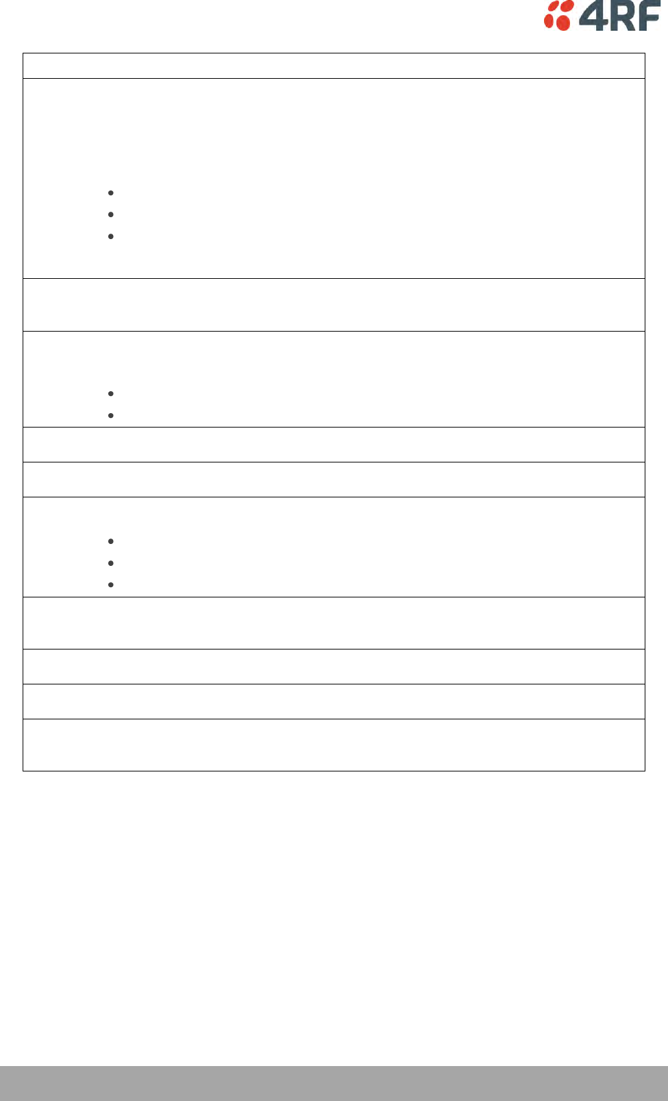
Accessory Kit
The accessory kit contains the following items:
Two mounting brackets and screws
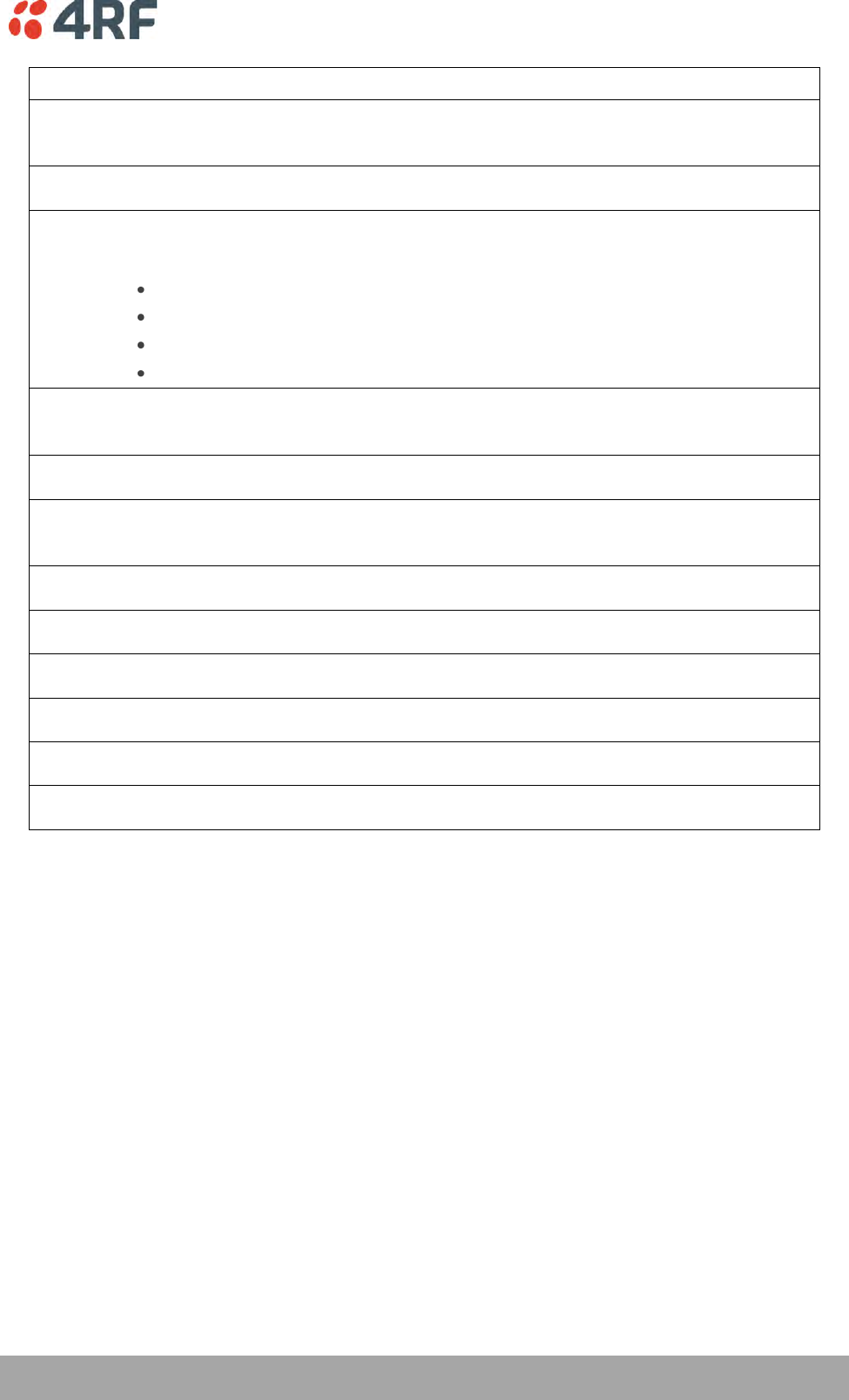
Two interface slot blanking plates
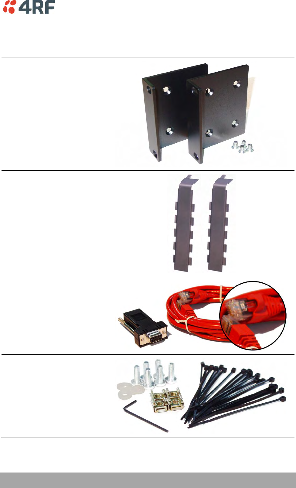
Setup cable (RJ-45 to RJ-45) 2 m
and RS-232 DB9 female adaptor
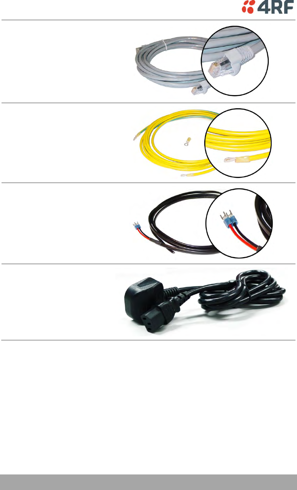
Hardware kit
(includes Allen key for fascia screws)
22 | Introduction
Aprisa XE User Manual
Alarm cable (RJ-45 to RJ-45) 5 m
Ground cable 5 m
DC power cable 3 m
(for use with the ±48 VDC, ±24 and
12 VDC low power power supplies)
AC power cable 2 m
(for use with the 110 / 230 VAC
power supply)
Preparation | 23
Aprisa XE User Manual
3. Preparation
Path Planning
Proper path planning is essential. When considering the components of your radio system, think about:
antenna selection and siting
coaxial cable selection
link budget
You can also use Surveyor to help you with path feasibility planning.
Surveyor is a path propagation calculator developed by 4RF to assist path planners quickly and efficiently
verify the viability of point-to-point transmission links deploying the Aprisa microwave radio systems.
The software program calculates the anticipated link performance for the transmission system elements
you have selected. However, it is not a substitute for in-depth path planning.
You will find Surveyor a valuable addition to your planning toolbox.
A copy of Surveyor is provided on the Aprisa CD supplied with this manual. You can download updates from
www.4rf.com.
Antenna Selection and Siting
Selecting and siting antennas are important considerations in your system design.
There are three main types of directional antenna that are commonly used with the radios parabolic grid,
Yagi and corner reflector antennas.
The antenna that should be used for a particular situation is determined primarily by the frequency of
operation and the gain required to establish a reliable link.
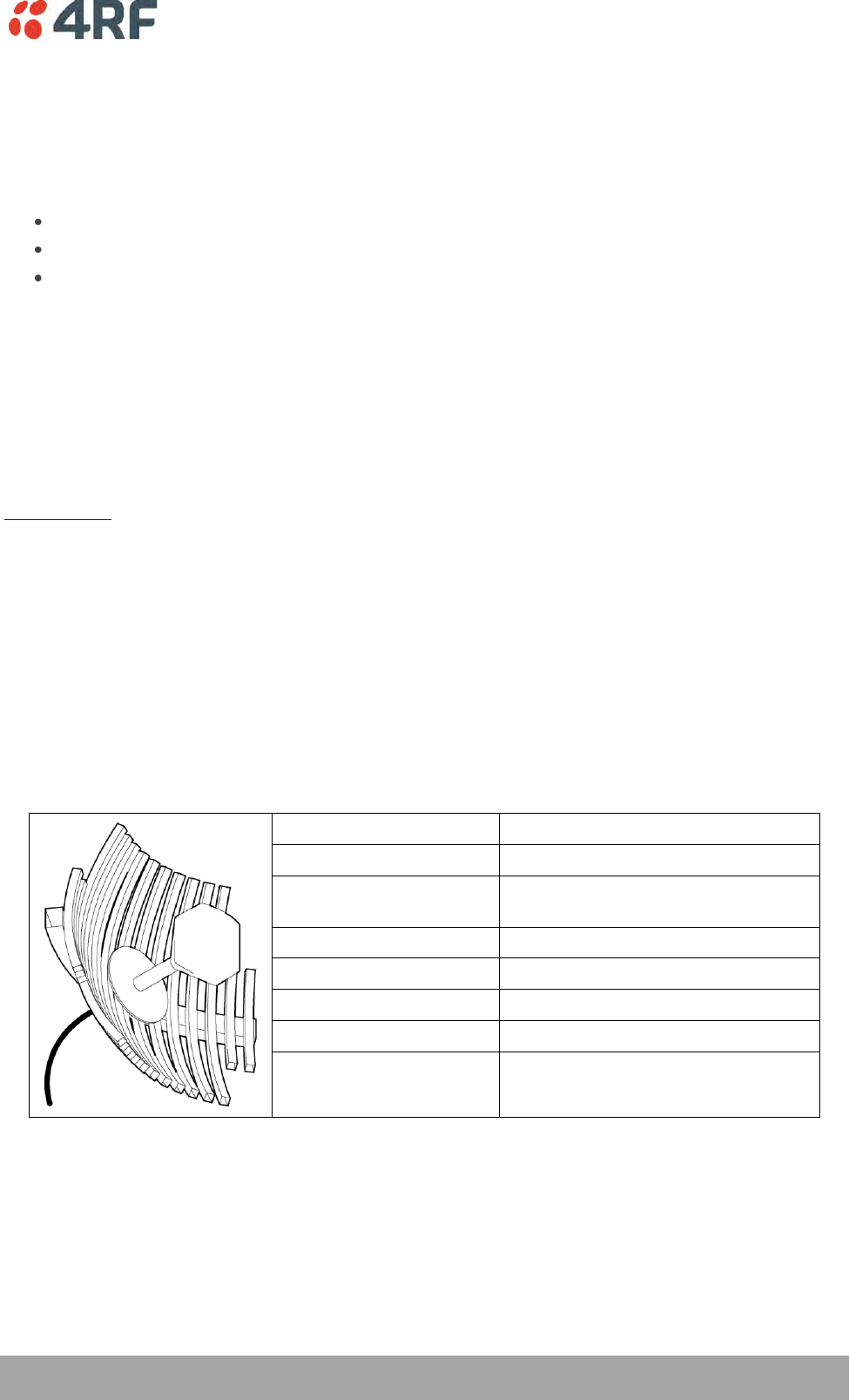
Parabolic Grid Antennas
Factor
Explanation
Frequency
Often used in 1350-2700 MHz bands
Gain
Varies with size (17 dBi to 30 dBi
typical)
Wind loading
Can be significant
Tower aperture required
Can be significant
Size
Range from 0.6 m to 3 m diameter
Front to back ratio
Good
Cost
High
24 | Preparation
Aprisa XE User Manual
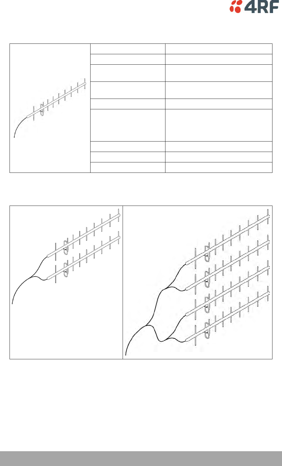
Yagi Antennas
Factor
Explanation
Frequency
Often used in 330-960 MHz bands
Gain
Varies with size (typically 11 dBi to 16
dBi)
Stackable gain increase
2 Yagi antennas (+ 2.8 dB)
4 Yagi antennas (+ 5.6 dB)
Wind loading
Less than a parabolic grid antenna
Tower aperture required
Unstacked: Less than a parabolic grid
antenna
Stacked: about the same as a
parabolic grid antenna
Size
Range from 0.6 m to 3 m in length
Front to back ratio
Low
Cost
Low
It is possible to increase the gain of a Yagi antenna installation by placing two or more of them in a stack.
The relative position of the antennas is critical.
Example of stacked antennas
Preparation | 25
Aprisa XE User Manual
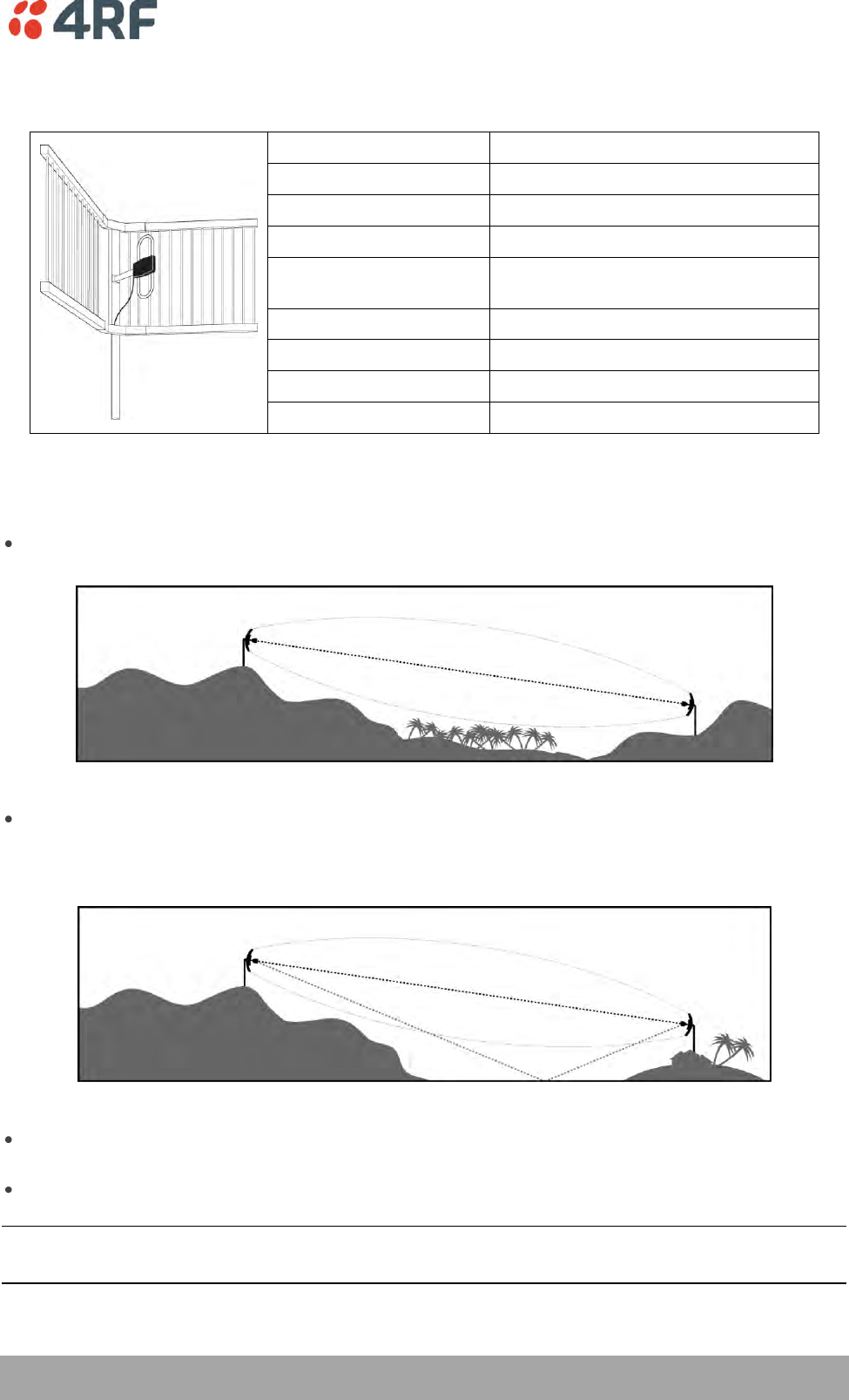
Corner Reflector Antennas
Factor
Explanation
Frequency
Often used in 330-960 MHz bands
Gain
Typically 10 dBd
Wind loading
Less than a parabolic grid antenna
Tower aperture required
About the same as a parabolic grid
antenna
Size
Range from 0.36 m to 0.75 m in length
Front to back ratio
High (typically 30 dB)
Beamwidth
Broad (up to 60°)
Cost
Medium
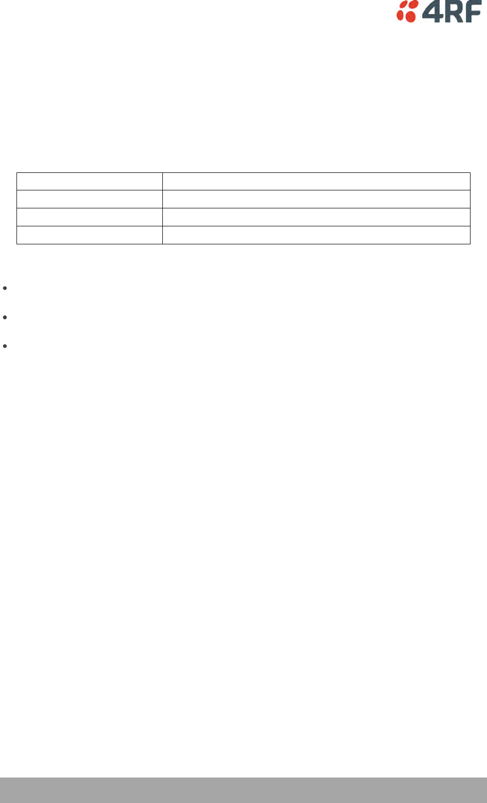
Antenna Siting
When siting antennas, consider the following points:
A site with a clear line of sight to the remote terminal is needed. Pay particular attention to trees,
buildings, and other obstructions close to the antenna site.
Example of a clear line-of-sight path
Any large flat areas that reflect RF energy along the link path, for instance, water, could cause
multipath fading. If the link path crosses a feature that is likely to cause RF reflections, shield the
antenna from the reflected signals by positioning it on the far side of the roof of the equipment
shelter or other structure.
Example of a mid-path reflection path
The antenna site should be as far as possible from other potential sources of RF interference such as
electrical equipment, power lines and roads.
The antenna site should be as close as possible to the equipment shelter.
Note: Wide angle and zoom photographs taken at the proposed antenna location (looking down the
proposed path), can be useful when considering the best mounting positions.
26 | Preparation
Aprisa XE User Manual
Coaxial Feeder Cables
To ensure maximum performance, it is recommended that you use good quality low-loss coaxial cable for
all feeder runs. For installations requiring long antenna cable runs, use Andrew Heliax™ or equivalent.
When using large diameter feeders, use a short flexible jumper cable between the feeder and the
terminal to reduce stress on the antenna port connector.
All coaxial cable has loss, that is, the RF energy traveling through it is attenuated. Generally speaking, the
larger the diameter of the cable, the less the loss. When selecting a coaxial cable consider the following:
Factor
Effect
Attenuation
Short cables and larger diameter cables have less attenuation
Cost
Smaller diameter cables are cheaper
Ease of installation
Easier with smaller diameter cables or short cables
When running cables:
Run coaxial cable from the installation to the antenna, ensuring you leave enough extra cable at each
end to allow drip loops to be formed.
For 19-inch rack mount installations, cables may be run from the front of the rack directly onto the
antenna port. They may also be run through the back of the rack to the front.
Terminate and earth or ground the cables in accordance with the manufacturers' instructions. Bond
the outer conductor of the coaxial feeder cables to the base of the tower mast.
Link Budget
All of the above factors (and many others not mentioned) combine in any proposed installation to create a
link budget. The link budget predicts how well the radio link will perform after it is installed.
Use the outputs of the link budget during commissioning testing to confirm the link has been installed
correctly, and that it will provide reliable service.
Preparation | 27
Aprisa XE User Manual
Site Requirements
Power Supply
Ensure that the correct power supply is available for powering the terminal.
The nominal input voltage for a terminal is 12, 24 or 48 volts DC or 115 / 230 volts AC rms.
The DC supply voltage is factory preset at time of order and cannot be adjusted in the field.
The terminal voltage is indicated on the chassis label by the DC input connector and on the specification
label fitted to the terminal.
WARNING:
Before connecting power, ground the chassis using the safety earth terminal on the
front panel.
Equipment Cooling
Mount the terminal so that air can flow through it. Do not obstruct the free flow of air around the
terminal. The two internal, speed-controlled fans fitted into the chassis provide sufficient cooling.
The operation of the fans is monitored and an alarm is raised under failure conditions.
The environmental operating conditions are as follows:
Operating temperature
-10°C to +50°C
Storage temperature
-20°C to +70°C
Humidity
Maximum 95% non-condensing
28 | Preparation
Aprisa XE User Manual
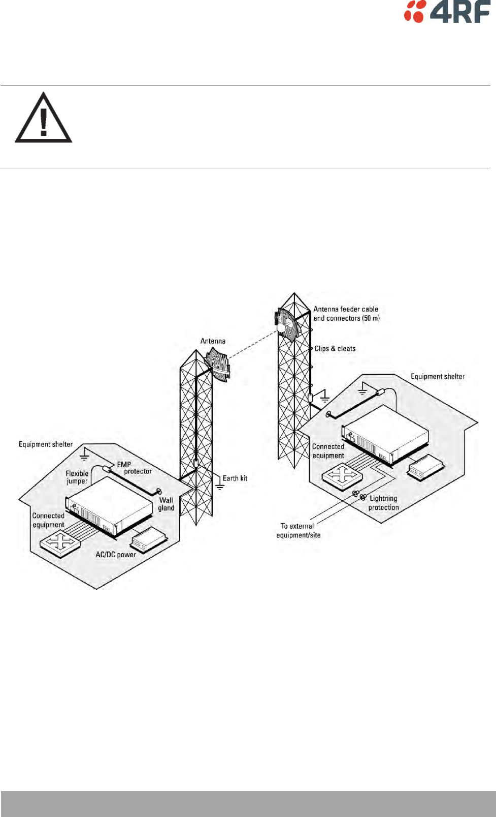
Earthing and Lightning Protection
WARNING:
Lightning can easily damage electronic equipment.
To avoid this risk, install primary lightning protection devices on any interfaces that
are reticulated in the local cable network.
You should also install a coaxial surge suppressor on the antenna port of the duplexer.
Earth the antenna tower, feeders and lightning protection devices in accordance with the appropriate
local and national standards. The diagram below shows the minimum requirements.
Use grounding kits as specified or supplied by the coaxial cable manufacturer to properly ground or bond
the cable outer.
About the Terminal | 29
Aprisa XE User Manual
4. About the Terminal
Introduction
The terminals operate in a number of frequency bands from 300 MHz up to 2.7 GHz carrying ethernet,
voice and data traffic over distances up to 100 kilometres.
They are designed to meet the demands of a wide range of low to medium capacity access and backhaul
applications.
The digital access terminal is a compact, powerful point-to-point linking solution with up to 64 Mbit/s of
radio link capacity, and customer-configurable interface options integrated within the radio platform.
30 | About the Terminal
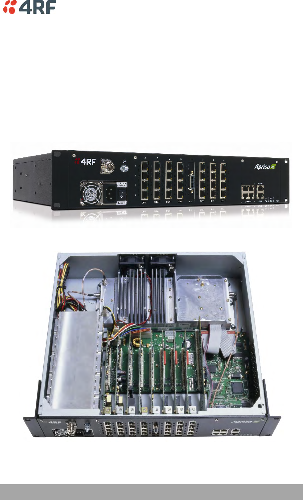
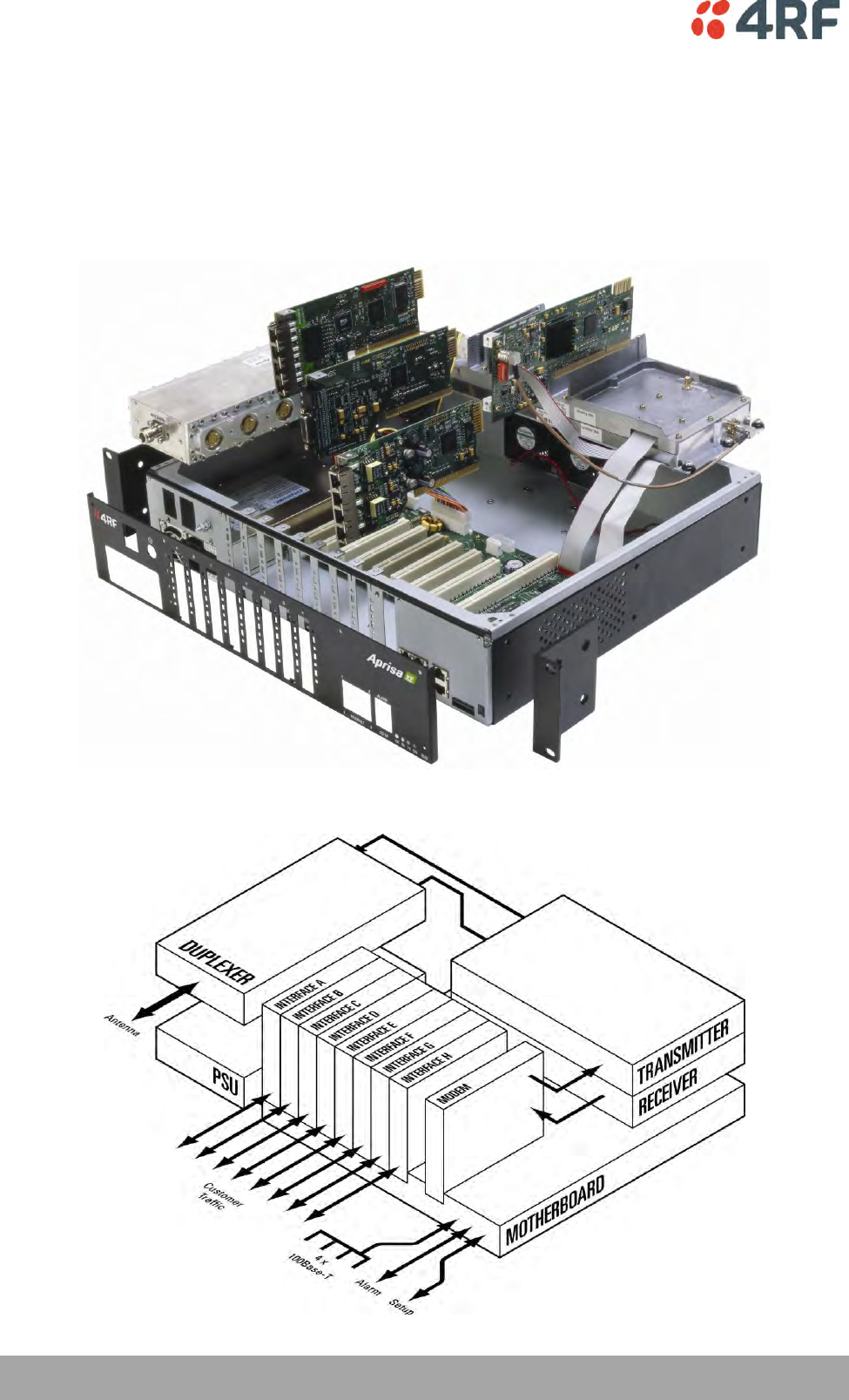
Aprisa XE User Manual
Modules
The terminal is modular in design, which helps reduce mean time to repair (MTTR). It is designed for 19-
inch rack mounting and is only 2U high for standard configurations.
The five main modules housed inside the chassis are the transceiver, modem, motherboard, power supply,
and duplexer. Interface cards are fitted into the eight interface slots on the motherboard. Modules are
interconnected via several buses on the motherboard. A duplexer can be mounted inside or outside the
chassis.
The interrelationships between the components are shown below:
About the Terminal | 31
Aprisa XE User Manual
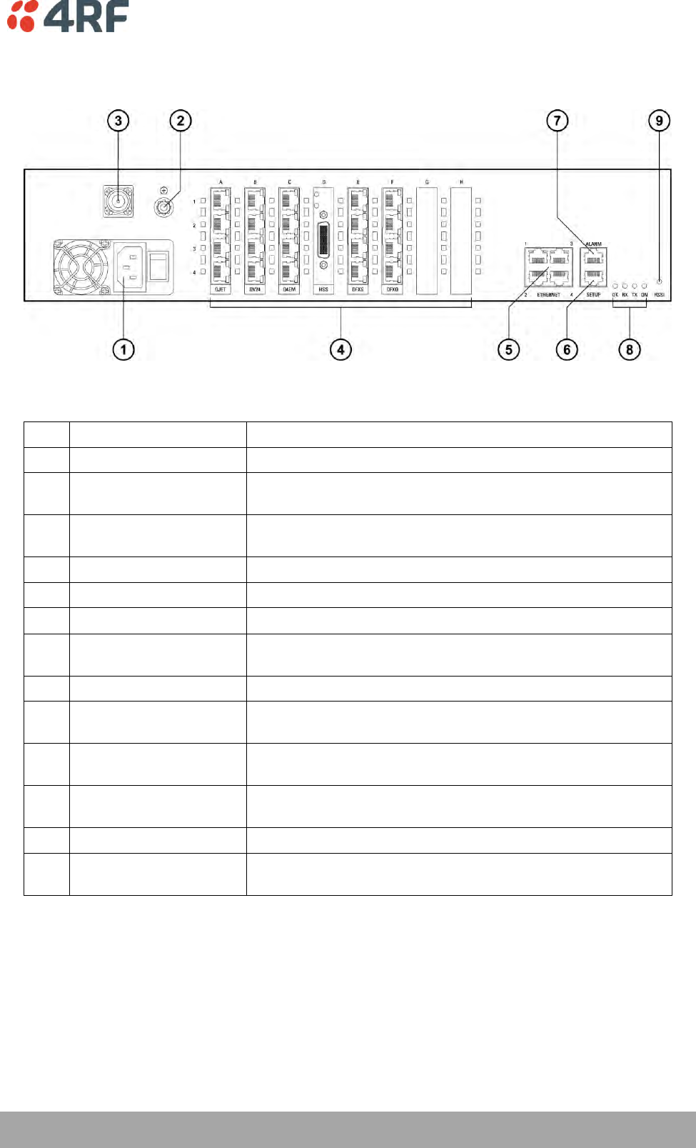
Front Panel Connections and Indicators
All connections to the terminal are made on the front panel of the terminal.
No.
Label
Description
1
AC or DC power input
DC and AC power supplies are available (AC is shown)
2
Safety earth stud
An M5 stud for connection to an external protection ground for
protection against electric shock in case of a fault.
3
Antenna connector
N-type 50Ω female connector for connection of antenna feeder
cable.
4
Interface slots A to H
Eight interface slots on the motherboard to fit interface cards.
5
ETHERNET
Integrated four-port layer 2 switch.
6
SETUP
RJ-45 serial connection to PC for initial configuration.
7
ALARM
RJ-45 connector for two external alarm input and four external
alarm output connections.
8
LED indicators
OK
Indicates normal operation and minor and major alarm
conditions.
RX
Indicates status of receive path including normal operation and
alarms such as BER, RSSI and loss of synchronization.
TX
Indicates status of transmit path including normal operation
and alarms such as forward / reverse power and temperature.
ON
Blue LED indicates that there is power to the terminal.
9
RSSI
RSSI test point suitable for 2 mm diameter multimeter test
lead pin.

32 | About the Terminal
Aprisa XE User Manual
Interface Card Types
Each terminal has eight interface slots labeled A to H. Each slot can be fitted with any interface card
type. Typically, the terminal is delivered pre-configured with the requested interface cards.
The following interface card types are currently available:
Name
Interface card type
Function
QJET
Quad E1/T1 interface card
Four E1 / T1 interfaces (Framed or Unframed).
Q4EM
Quad 4 wire E&M interface card
Four 4 wire E&M voice channels
DFXS
Dual 2 wire FXS interface card
Two 2 wire loop signalling foreign exchange
subscriber (POTS) channels
DFXO
Dual 2 wire FXO interface card
Two 2 wire loop signalling foreign exchange office
channels
HSS
High-Speed Synchronous
interface card
A single high speed serial data channel configured
as synchronous V.24, V.35, X.21, V.36 / RS-449,
or RS-530.
QV24
Quad V.24 serial interface card
Four V.24 / RS-232 serial data channels
Synchronous and asynchronous
Mounting and Installing the Terminal | 33
Aprisa XE User Manual
5. Mounting and Installing the Terminal
This section covers installing the hardware associated with the terminal. Before you begin a terminal
installation, read this section thoroughly.
CAUTION:
You must comply with the safety precautions in this manual or on the product itself.
4RF Limited does not assume any liability for failure to comply with these
precautions.
Required Tools
No special tools are needed to install the terminal other than those required to physically mount the
terminal into the rack.
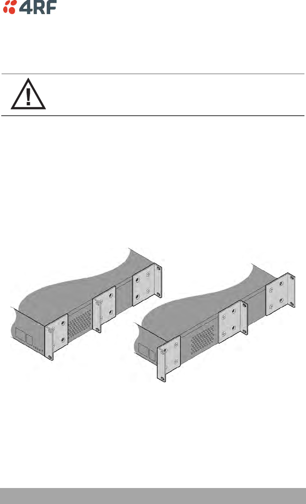
Installing the Terminal
The terminal is designed for 19-inch rack mounting and is supplied with rack mounting brackets. The rack
brackets can be front, mid, or rear mounted (as shown below) to suit individual installation requirements.
Once the rack brackets are attached, carefully lift the terminal into position in the rack, and fasten with
screws and washers.
34 | Mounting and Installing the Terminal
Aprisa XE User Manual
Installing the Antenna and Feeder Cable
Carefully mount the antenna following the antenna manufacturers' instructions. Run feeder cable from the
antenna to the terminal mounting location.
Lightning protection must be incorporated into the antenna system. For more information, please contact
Customer Support.
WARNING:
When the link is operating, there is RF energy radiated from the antenna.
Do not stand in front of or touch the antenna while the terminal is operating.
1. Fit the appropriate male or female N-type connector to the antenna feeder at the antenna end.
Carefully follow the connector manufacturers' instructions.
2. Securely attach the feeder cable to the mast and cable trays using cable ties or cable hangers. Follow
the cable manufacturer's recommendations about the use of feeder clips, and their recommended
spacing.
3. Connect the antenna and feeder cable. Ensure the N-type connector is tight. Weatherproof the
connection with a boot, tape, or other approved method.
4. Fit the appropriate N-type male connector to the antenna feeder at the terminal end (the terminal is
N-type female). Carefully follow the connector manufacturer's instructions.
5. Connect the feeder cable to the antenna port on the terminal. Use a jumper cable, if needed. Ensure
the N-type connector is tight.
6. Connect a coaxial surge suppressor or similar lightning protector between the feeder and jumper
cables (or at the point where the cable enters the equipment shelter).
Earth the case of the lightning protector to the site Lightning Protection Earth. Also earth the terminal
M5 earth stud to a protection earth.
Mounting and Installing the Terminal | 35
Aprisa XE User Manual
External Alarms
Two external alarm inputs and four external alarm outputs are provided on the RJ-45 ALARM connector on
the front panel. These enable an internal alarm to provide an external alarm to the network operator's
existing network management system via contact closure or opening, or for an external alarm to be
transported via the radio link.
The latency for an alarm presented on an external alarm input to the alarm being output on an external
alarm output is < 2 seconds.
Alarm outputs are isolated semiconductor relay type contacts rated 0 to 60 VDC or AC rms with a
maximum current of 100 mA.
Alarm inputs are isolated current detectors with an operating voltage range of 9 to 60 VDC or AC rms
(effective current threshold of 5.0 to 6.5 mA constant current).
The common reference potential for the two external alarm inputs must be applied to pin 3 and the
common reference potential for the four external alarm outputs must be applied to pin 4.
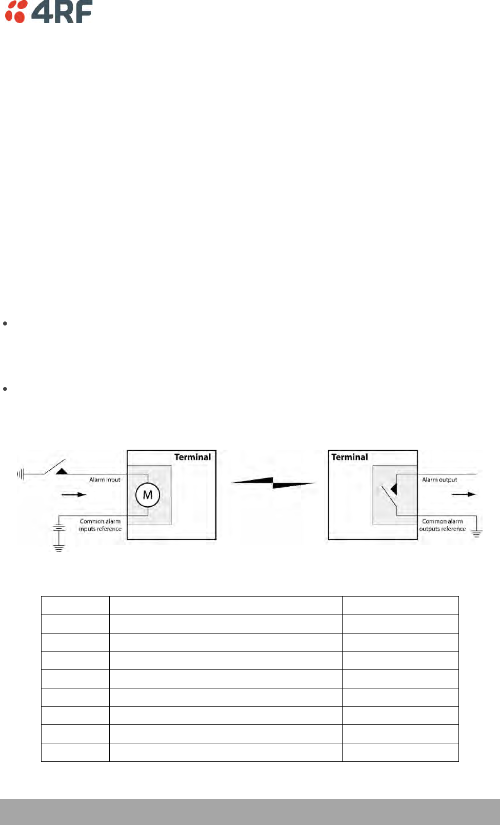
Alarm Circuit Setup
A typical alarm circuit setup is:
An external battery applied to the ‘common alarm inputs reference’ and a normally open relay
contact connected to the alarm input. Closing the contact applies the source to the alarm input
detector which turns the alarm on (setup for ‘alarm on when source on’). See ‘Configuring the
External Alarm Inputs’ on page 81 for the setup options.
An external earth applied to the ‘common alarm outputs reference’ and a ground contact detector
connected to the alarm output. When the alarm is on (active), the external alarm output relay contact
closes (setup for ‘relay closed when alarm on’). See ‘Configuring the External Alarm Outputs’ on page
83 for the setup options.
The terminal front panel RJ-45 ALARM connections are:
RJ-45 pin
Connection description
TIA-568A wire colour
1
External alarm input 1
green / white
2
External alarm input 2
green
3
Common reference for alarm inputs 1 to 2
orange / white
4
Common reference for alarm outputs 1 to 4
blue
5
External alarm output 1
blue / white
6
External alarm output 2
orange
7
External alarm output 3
brown / white
8
External alarm output 4
brown

36 | Mounting and Installing the Terminal
Aprisa XE User Manual
Interface Cabling
All interface cabling connections are made with RJ-45 male connectors which plug into the front of the
interface cards (see ‘Interface Connections’ on page 257).
QJET Q4EM DFXO and DFXS
The cabling to the QJET, Q4EM, DFXO and DFXS interface cards must have a minimum conductor size of
0.4 mm2 (26 AWG).
Ethernet
Standard Ethernet network cables are used for all Ethernet port cabling.
Mounting and Installing the Terminal | 37
Aprisa XE User Manual
Power Supplies
US and Canada: Installations should be in accordance with US National Electrical Code ANSI / NFPA 70,
and Canadian Electrical Code, Part 1 C22.1.
WARNING:
Do not apply power to the terminal until you have completed installing the interface
cards and connecting the antenna.
Before disconnecting the safety earth during maintenance, remove AC or DC power
supply connections, antenna cable and all interface cables from the terminal.
DC Power Supply
There are four DC power supply options for the terminal; 12 VDC, 12 VDC Low Power, 24 VDC and 48 VDC.
The DC inputs are polarity critical so the DC voltage must be applied with the correct polarity.
Nominal voltage
Input voltage
range
Maximum Power
input
Maximum input
current
Recommended
DC breaker
rating
+12 VDC LP
10.5 to 18 VDC
53 W
5 A
8 A
±12 VDC
10.5 to 18 VDC
180 W
18 A
25 A
±24 VDC
20.5 to 30 VDC
180 W
8 A
10 A
±48 VDC
40 to 60 VDC
180 W
4 A
5 A
CAUTION: An all-pole switch or DC circuit breaker of the rating shown in the table above must be fitted
between the terminal DC input and the DC power source.
Each terminal or MHSB terminal should have its own separate fuse or DC circuit breaker.
12 VDC / 24 VDC / 48 VDC Power Supply
The power supply DC input is isolated from ground, so the DC power input can be either positive grounded
or negative grounded. The positive or negative terminal should be connected to ground.
12 VDC LP Power Supply
The 12 VDC Low Power is a high efficiency power supply for low power consumption applications up to a
maximum of 53 watts input power (see ‘Power Consumption’ on page 312).
The DC input on this power supply is not isolated from ground as the negative input is internally connected
to ground via the Aprisa XE chassis. The DC power input for this power supply must be a positive 12 V
supply with the negative grounded.
38 | Mounting and Installing the Terminal
Aprisa XE User Manual
DC Power Input Cabling
The DC power input is terminated on the front panel of the terminal with two high-current M3 screw
clamps for the positive and negative DC input and a M5 stud for the earth connection.
The DC power cables have pre-terminated lugs to fit into the power input M3 screw clamps on one end and
bare wire at the other end.
The appropriate power cable for the power supply ordered is included in the accessory kit.
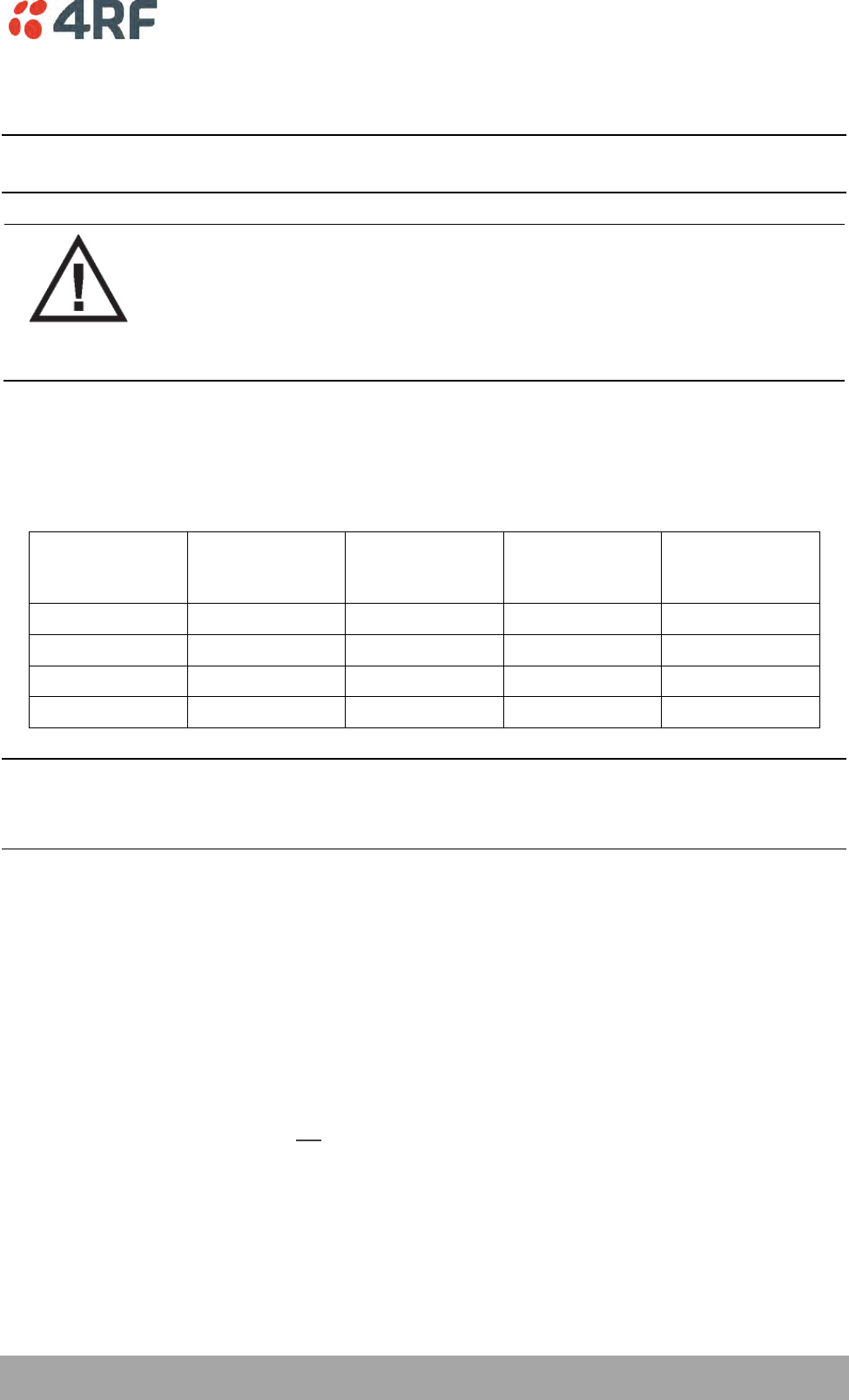
12 VDC LP / 24 VDC / 48 VDC Cable
The 12 VDC LP, 24 VDC and 48 VDC power supplies are supplied with a 3 metre red / black cable of
2.0 mm2 (23 strands of 0.32 mm2).
Terminal
Power input
Cable colour
+V
Positive DC input
Red
-V
Negative DC input
Black
Mounting and Installing the Terminal | 39
Aprisa XE User Manual
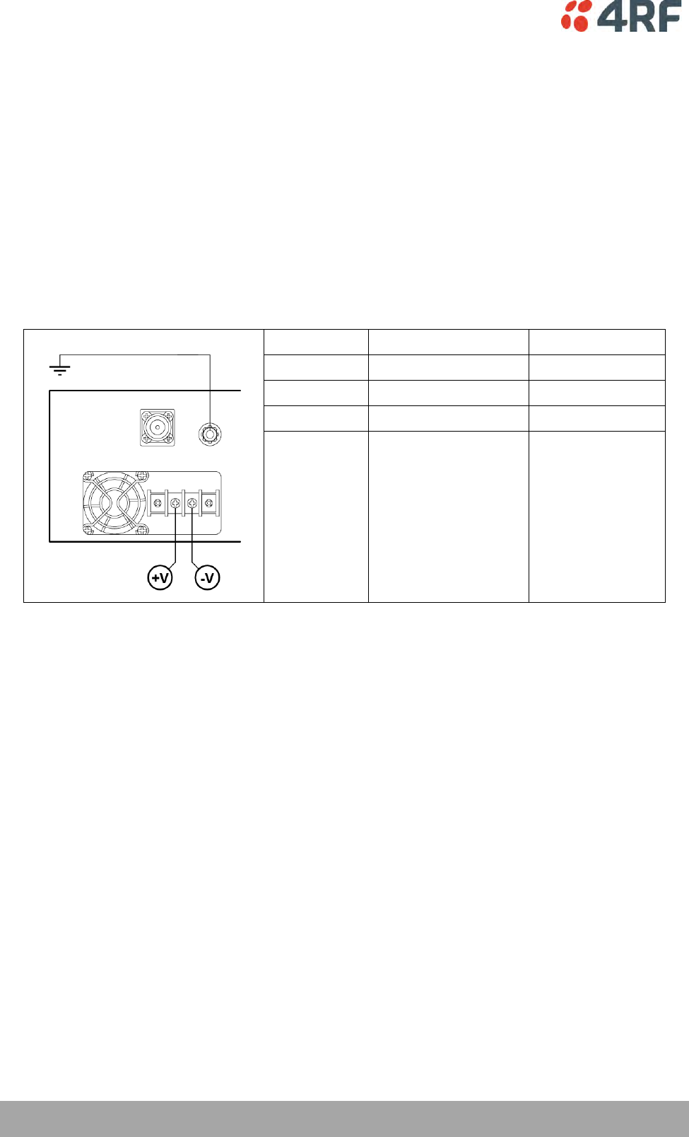
12 VDC Cable
The 12 VDC power supply is supplied with a 3 metre red/black cable of two pairs of 2.3 mm2 (72 strands of
0.2 mm2) making a total of 4.6 mm2 per connection. This increase in wire size is to carry the increased
current consumption of the 12 VDC supply (max 18 Amps per terminal).
This 3 metre cable is engineered to power a fully loaded terminal from a 12 VDC supply. A longer cable
should not be used as the additional voltage drop could cause the power supply to fail.
If longer cable runs are required between the 12 VDC power supply and the terminal, it is suggested that
high current distribution bus bars are used to feed the rack and the supplied power cable used between
the bus bars and the terminals.
Terminal
Power input
Cable colour
+V
Positive DC input
Red
-V
Negative DC input
Black
1. Fit both pairs of lugs into the terminal screw
clamps.
2. Twist the other ends together when fitting
to the source.
40 | Mounting and Installing the Terminal
Aprisa XE User Manual
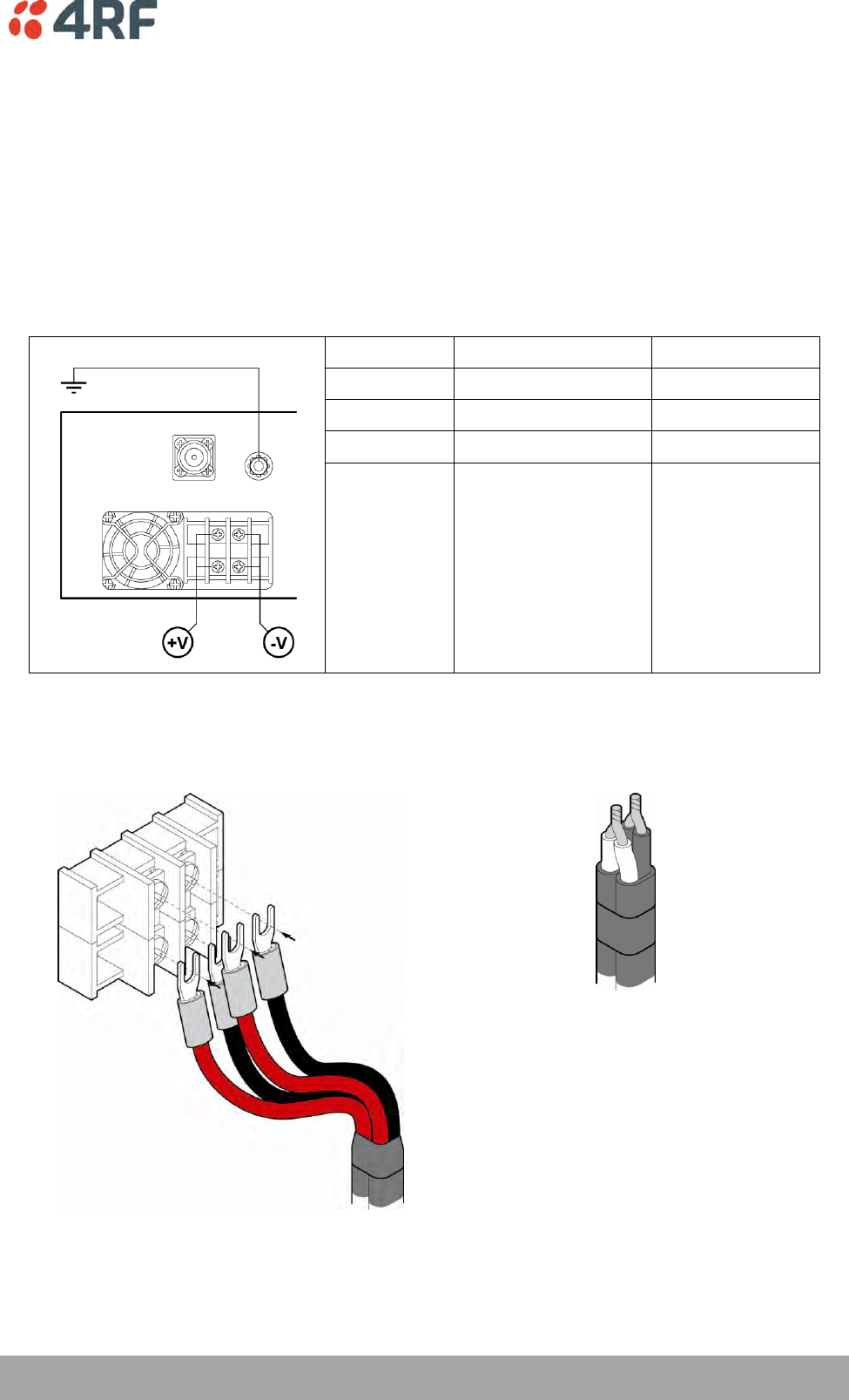
AC Power Supply
There is one AC power supply for the terminal. This AC power supply is auto-sensing to operate with a
nominal input voltage of 115 Vrms or 230 Vrms.
The power input is terminated on the front panel of the terminal using a standard IEC plug. This power
supply has a power on/off switch.
A power cable is included in the accessory kit and is pre-fitted with an IEC socket connector and the
country-specific plug that was specified when the order was placed.
Nominal
voltage
Input voltage
range
Maximum Power
input
Max VA
Frequency
115 VAC
103 - 127 Vrms
180 W
400 VA
47 - 63 Hz
230 VAC
207 - 254 Vrms
180 W
400 VA
47 - 63 Hz
Terminal
Power input
Cable colour
E
Earth
Green/yellow
N
Neutral
Blue
L
Line / Phase
Brown
Important: Please check with your local power authority about correct colour usage and pinouts.
AC power cords used must be in accordance with national requirements.
Norway and Sweden: PLUGGABLE CLASS I EQUIPMENT intended for connection to a telephone network or
similar communications system requires a label stating that the equipment must be connected to an
earthed mains socket outlet.
Mounting and Installing the Terminal | 41
Aprisa XE User Manual
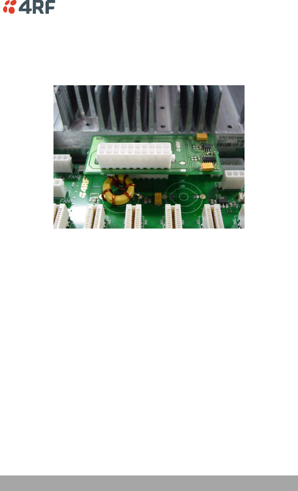
Brownout Recovery Module
A Brownout Recovery Module (BRM) is factory fitted to the Aprisa XE motherboard power connector when
the radio is fitted with an AC power supply.
The AC power supply has a safety mechanism that trips the power if it detects a power input brownout.
The BRM restarts the power supply after 3 seconds.
42 | Mounting and Installing the Terminal
Aprisa XE User Manual
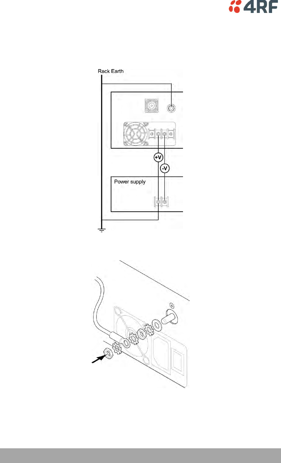
Safety Earth
The terminal chassis must have a protection / safety earth connected between the terminal earth stud
and a common protection earth in the rack. The DC power input can be either positive grounded or
negative grounded depending on the power supply system available.
Ground the terminal chassis using the terminal earth stud on the front panel as shown:
Mounting and Installing the Terminal | 43
Aprisa XE User Manual
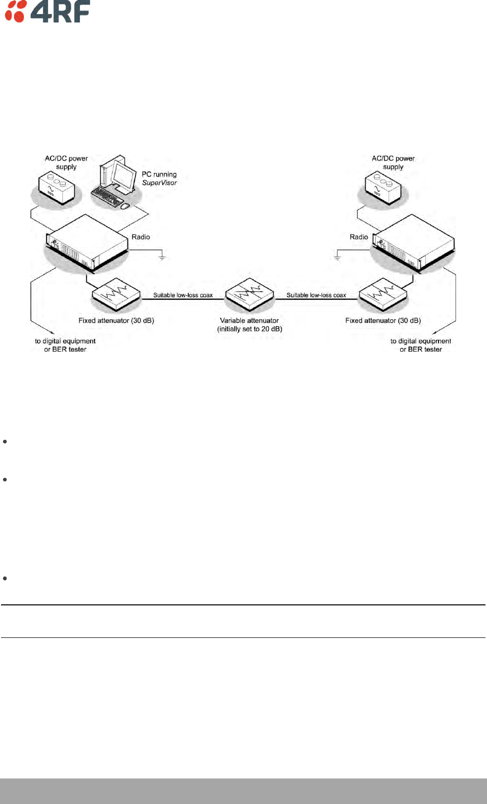
Bench Setup
Before installing the link in the field, it is recommended that you bench-test the link. A suggested setup
for basic bench testing is shown below:
When setting up the equipment for bench testing, note the following:
Earthing—the terminal should be earthed at all times. The terminal earth stud must be connected to a
protection earth.
Attenuators— In a bench setup, there must be 60 - 80 dB at up to 3 GHz of 50 ohm coaxial attenuation
(capable of handling the transmit power of +35dBm) between the terminals’ N type antenna
connectors.
This can be achieved with two fixed attenuators fitted to the antennas 'N' connectors and a variable
attenuator with a ≥ 60 dB range. You can use other attenuator values as long as you consider the
transmit power output level (max +33 dBm) and the receiver signal input (max -20 dBm).
Cables—use double-screened coaxial cable that is suitable for use up to 3 GHz at ≈ 1 metre.
CAUTION: Do not apply signals greater than -20 dBm to the antenna connection as they can damage the
receiver.
Connecting to the Terminal | 45
Aprisa XE User Manual
6. Connecting to the Terminal
Connecting to the Terminal's Setup Port
You can configure basic terminal settings by connecting to the terminal using the Setup cable. This can be
useful if you need to confirm the terminal's IP address, for example.
You can password-protect the setup menu to prevent unauthorized users from modifying terminal settings.
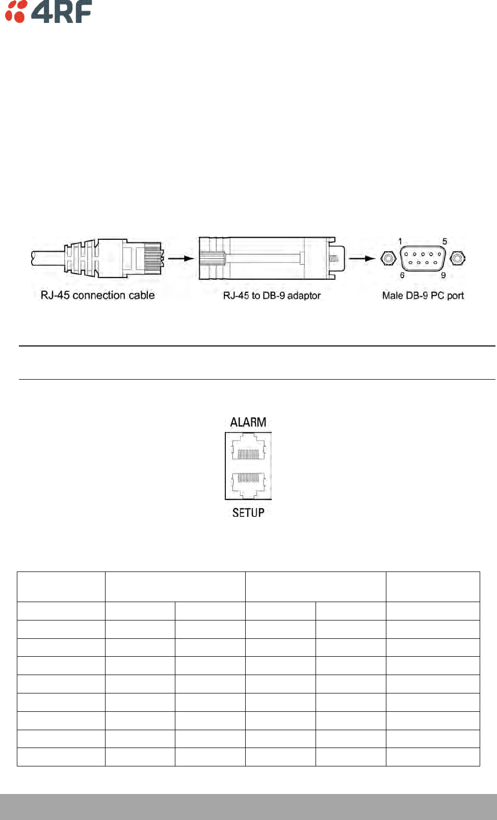
A straight RJ-45 connection cable and a RJ-45 to DB-9 adapter is provided with each terminal.
1. Plug the DB-9 into serial port of the PC.
2. Plug the RJ-45 connection cable into the adaptor as shown below:
3. Plug the other end of the RJ-45 connection cable into the SETUP port of the terminal.
Note: Connecting the PC serial port to the Interface Cards or ALARM connectors may result in damage
to the PC or terminal.
Ensure that the RJ-45 connection cable is connected to the RJ-45 connector marked 'SETUP'.
Cable pinouts (RJ-45 to DB-9)
If you need a conversion connector or cable, refer to the following table:
Console port
(DCE, RJ-45)
RJ-45 to RJ-45 cable
RJ-45 to DB-9 adaptor
PC port
(DTE, DB-9)
Signal
RJ-45 pin
RJ-45 pin
RJ-45 pin
DB-9 pin
Signal
RTS
1
1
1
7
RTS
DTR
2
2
2
4
DTR
TXD
3
3
3
3
TXD
GND
4
4
4
5
GND
GND
5
5
5
NC
NC
RXD
6
6
6
2
RXD
DSR
7
7
7
6
DSR
CTS
8
8
8
8
CTS
46 | Connecting to the Terminal
Aprisa XE User Manual
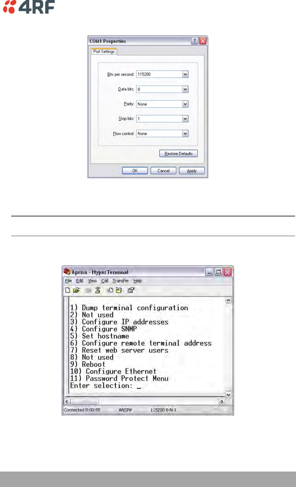
Configure the PC COM Port Settings
Terminal emulation software e.g. HyperTerminal is used to setup the basic configuration of a terminal.
The PC's COM port settings must be setup as follows:
Bits per second
115200
Data bits
8
Parity
None
Stop bits
1
Flow Control
None
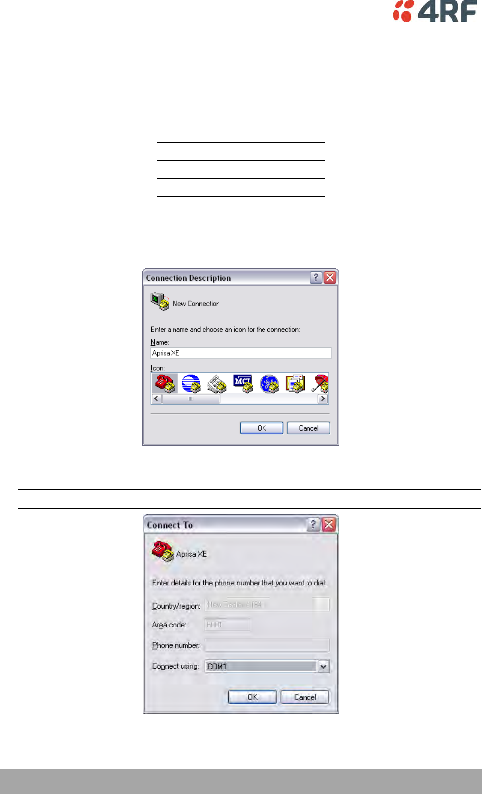
Start a HyperTerminal Session
1. On the PC, select Start > Programs > Accessories > Communications > HyperTerminal.
2. Enter a name for the connection and click OK.
3. Select the designated COM Port from the Connect Using drop-down box. Ensure it is the same COM
port that you configured earlier on your PC. Click OK.
Note: The Country/region, Area code, and Phone number information will appear automatically.
Connecting to the Terminal | 47
Aprisa XE User Manual
4. Set the COM Port settings as follows:
5. When you have completed the settings, click OK, which will open the HyperTerminal window.
6. Apply power to the terminal.
Note: If power was applied to the terminal before launching HyperTerminal, hit the Enter key to
initiate the link.
When the terminal has completed startup, you will be presented with the Setup menu:
48 | Connecting to the Terminal
Aprisa XE User Manual
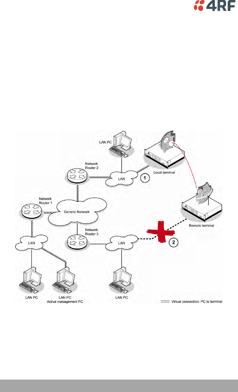
Connecting to the Terminal's Ethernet Interface
The main access to a terminal for management is with the ethernet interface using standard IP
networking. There should be only one ethernet connection from the terminal to the management network.
The terminals are pre-configured to use IP addressing in one of the common 'non-routable' IP address
ranges. This means the terminals are usually recognized by your operating system without any
reconfiguration.
However, you should change these default addresses (see ‘Changing the Terminal’s IP Address’ on page
64) to comply with your IP addressing scheme.
In the example below, the active management PC must only have one connection to the link as shown by
path . There should not be any alternate path that the active management PC can use via an alternate
router or alternate LAN that would allow the management traffic to be looped as shown by path .

Connecting to the Terminal | 49
Aprisa XE User Manual
PC Requirements for SuperVisor
SuperVisor requires the following minimum PC requirements:
Microsoft Windows 2000, NT, XP, Vista or Windows 7
Personal computer with 1.6 GHz Pentium IV
512 MB of RAM
200 MB of free hard disk space
Ethernet interface (Local Area Network)
COM port
Web browser with a Java plug-in such as Mozilla FireFox (recommended), Microsoft Internet
Explorer 5.0, or Netscape Navigator 6.0, but SuperVisor also supports other major web browsers.
Java JRE 1.6.
Note: Mozilla Firefox, Internet Explorer and the Java JRE are provided on the Aprisa CD (see ‘Aprisa XE CD
Contents’ on page 20).
50 | Connecting to the Terminal
Aprisa XE User Manual
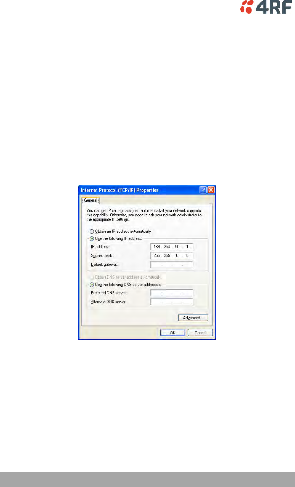
PC Settings for SuperVisor
To change the PC IP address:
If your PC has previously been used for other applications, you may need to change the IP address and the
subnet mask settings. You will require Administrator rights on your PC to change these.
Windows XP example: Configure IP settings
1. Open the 'Control Panel'.
2. Open 'Network Connections' and right click on the 'Local Area Connection' and select 'Properties'.
3. Click on the 'General' tab.
4. Click on 'Internet Protocol (TCP/IP)' and click on properties.
5. Enter the IP address and the subnet mask (example as shown).
6. Click 'OK' then close the Control Panel.
If the terminal is on a different subnet from the network the PC is on, set the PC default gateway address
to the network gateway address which is the address of the router used to connect the subnets (for
details, consult your network administrator).
Connecting to the Terminal | 51
Aprisa XE User Manual
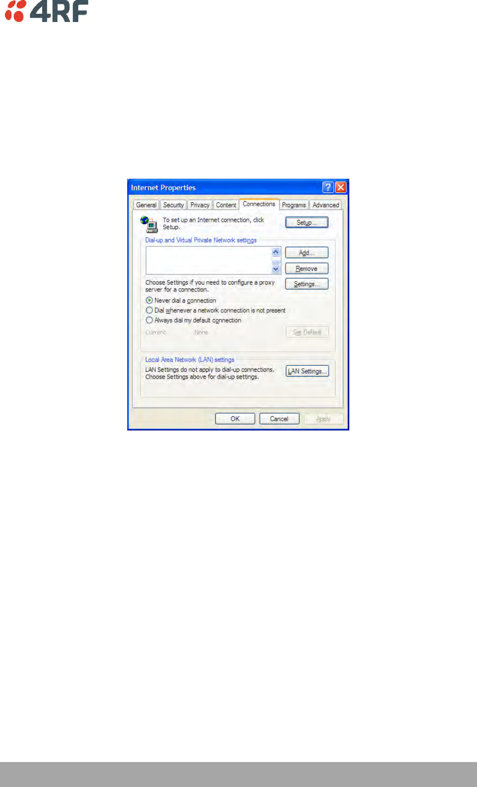
To change the PC connection type:
If your PC has previously been used with Dial-up connections, you may need to change your PC Internet
Connection setting to 'Never dial a connection'.
Windows XP example: Configure Windows to Never Dial a Connection
1. Open the 'Control Panel'.
2. Open 'Internet Options' and click on the 'Connections' tab.
3. Click the 'Never dial a connection' option.
4. Click 'OK' then close the Control Panel.
52 | Connecting to the Terminal
Aprisa XE User Manual
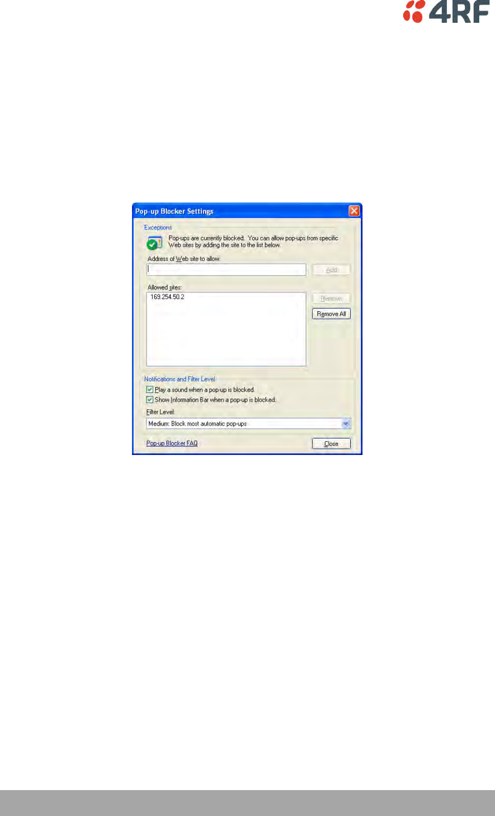
To change the PC pop-up status:
Some functions within SuperVisor require Pop-ups enabled e.g. saving a MIB
Windows XP example: Configure explorer to enable Pop-ups
1. Open the 'Control Panel'.
2. Open 'Internet Options' and click on the 'Privacy' tab.
3. Click on 'Settings'.
4. Set the 'Address of Web site to allow' to the terminal address or set the 'Filter Level' to 'Low: Allow
Pop-ups from secure sites' and close the window.
5. Click 'OK' then close the Control Panel.
Connecting to the Terminal | 53
Aprisa XE User Manual
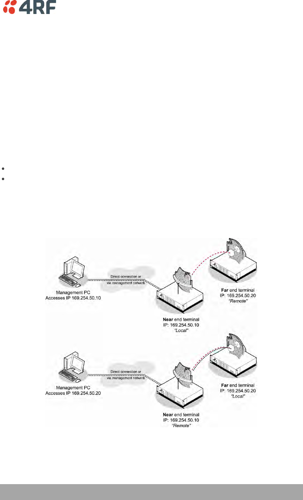
IP Addressing of Terminals
When logging into a link, it is important to understand the relationship between the Local / Remote and
the Near end / Far end terminals.
The Near end terminal is the terminal that has its ethernet port physically connected to your IP network.
The Far end terminal is the terminal that is at the other end of the link from the Near end terminal and
communicates through the management connection over the radio link to the Near end terminal.
The Local terminal is the terminal that SuperVisor is logged into and is displayed on the left hand side of
the SuperVisor screen. The Local terminal can be the Near end or Far end terminal.
The Remote terminal is the terminal that is at the other end of the link from the Local terminal and is
displayed on the right hand side of the SuperVisor screen.
To prevent confusion when operating SuperVisor, determine the IP address of the Near end terminal and
log into that terminal. This is now the Local terminal.
The distinction is important as:
Some functions can only be carried out on the Local terminal.
Having different configurations at each end of the link will disrupt communications between the
terminals. In these circumstances it is important to make changes to the Far end terminal of the link
first. The link is then lost only until the near end configuration is completed and communication
restored.
If the Near end terminal is modified first, the link is lost for much longer as staff will have to either
physically visit the Far end terminal to restore the link, or restore the near end to match the far end,
re-establish the link, then start the process again, this time with the Far end terminal first.
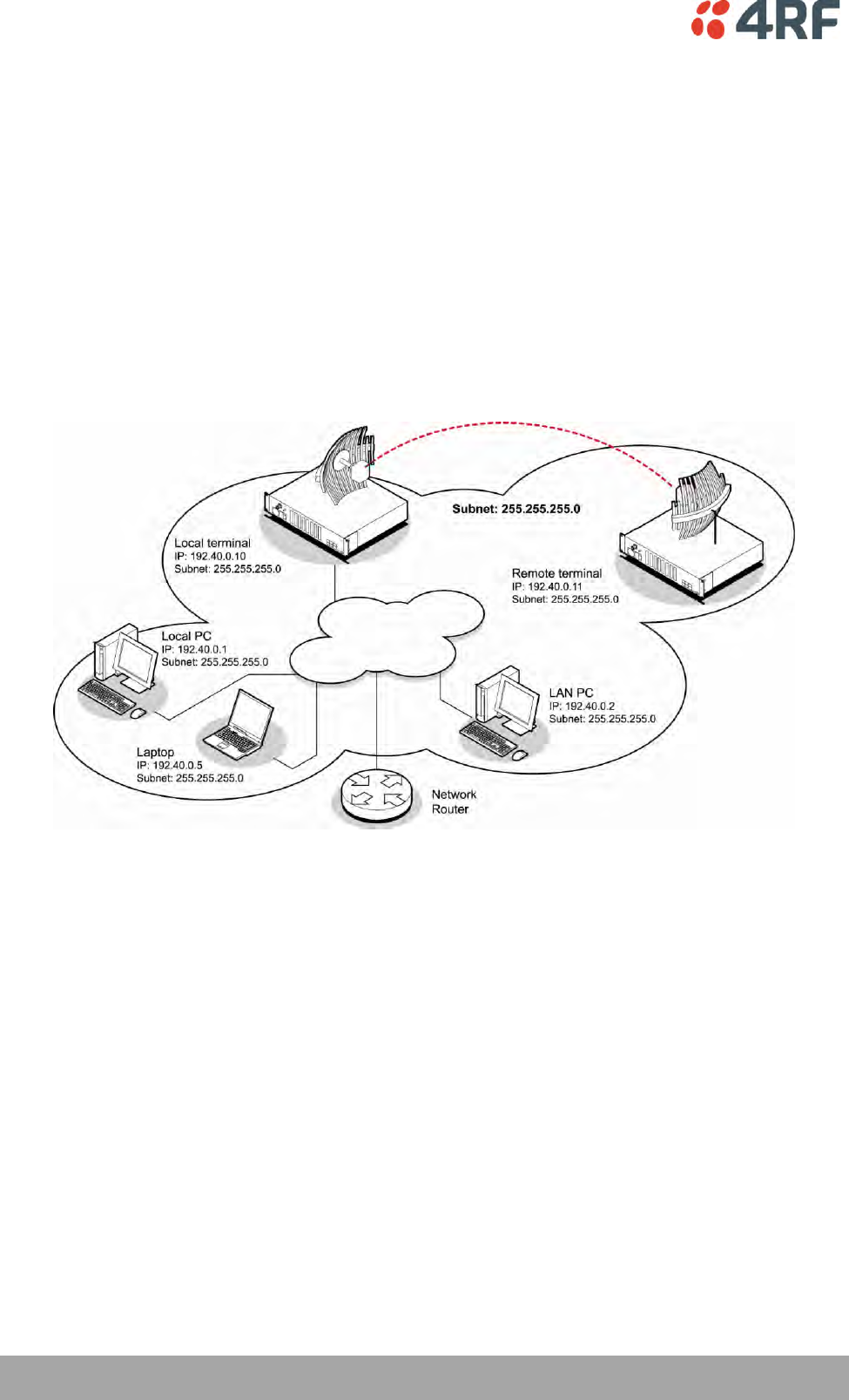
54 | Connecting to the Terminal
Aprisa XE User Manual
Network IP Addressing
Same Subnet as the Local PC
The following diagram shows a link interconnected on the same subnet as the local PC terminal used for
configuration.
In this example, the local PC, as well as the local and remote terminals, are on the same subnet and
therefore have the same subnet mask 255.255.255.0.
This will allow the PC and the terminals to communicate with each other.
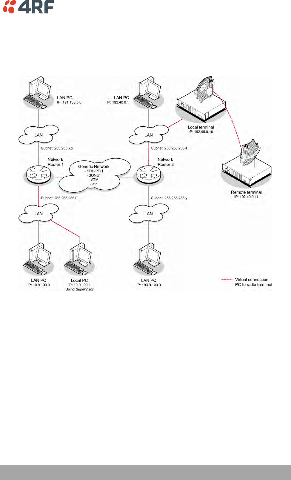
Connecting to the Terminal | 55
Aprisa XE User Manual
Different Subnet as the Local PC
The following diagram shows a link interconnected on a different subnet as the local PC used for
configuration, and communicating through a network. This can be achieved on the condition that network
router(s) 1 and 2 are programmed to recognize each other and the various subnets on the overall network.

Managing the Terminal | 57
Aprisa XE User Manual
7. Managing the Terminal
The command line setup menu can be used to:
Provide basic access to the terminal to set IP addresses
Check or set basic settings of the terminal
4RF SuperVisor is an embedded element manager for the Aprisa XE terminal which is used to:
Configure radio and interface parameters
Setup cross connections between traffic interfaces
Monitor performance, terminal status and alarm details
The Setup Menu
1. Initiate the link by either applying power to the terminals or, if the terminals are already powered up,
pressing the Enter key.
2. At the prompt, enter your selection:
Selection
Explanation
1)
Dump terminal
configuration
This shows basic terminal data such as Terminal ID, IP data
and radio parameters of TX and RX frequency, TX power,
modulation type and channel size.
2)
Not used
3)
Configure IP addresses
Use this if you want to set the IP address, subnet mask or
gateway address of the local terminal.
4)
Configure SNMP
Use to display SNMP settings, setup the SNMP Access Controls
and Trap Destinations and reset SNMP settings to defaults.
5)
Set hostname
Use this to set a name that can be used in conjunction with
DNS.
6)
Configure remote
terminal address
Use this to set the IP address of the remote terminal.
7)
Reset web server users
Deletes all existing usernames and passwords in the ‘User
Table’ and restores default usernames and passwords.
8)
Not used
9)
Reboot
Reboots the terminal.
10)
Configure Ethernet
Use this to display the Ethernet configuration and reset the
Ethernet settings to the defaults.
11)
Password Protect Menu
Use this to password-protect the menu to prevent
unauthorized users from modifying terminal settings.
The password is setupxe.
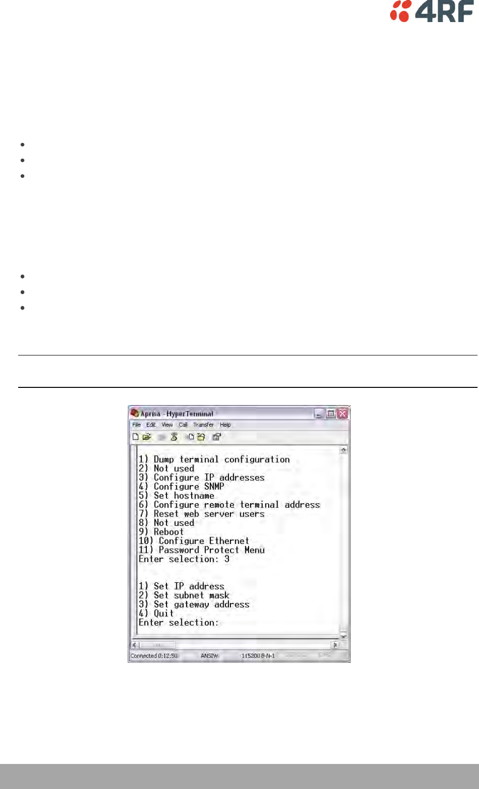
58 | Managing the Terminal
Aprisa XE User Manual
To Get or Set the IP Address of a Terminal Using Setup
To get the IP address of a terminal using setup:
1. At the prompt, type 1 and enter.
The following information appears:
the IP addresses of the local and remote terminals
the subnet mask and gateway of the local terminal
the TFTP of the remote terminal
To set the IP address of a terminal using setup:
1. At the prompt, enter 1.
2. Enter 3 to configure the local terminal IP address.
Set the following for the terminal using the standard format xxx.xxx.xxx.xxx:
1) IP address
2) Subnet mask
3) Gateway address
3. Enter 4 (Quit) to return to the main menu.
4. Enter 6 to configure the remote terminal IP address.
Important: You must ensure that the IP addresses of the local and remote terminals are on the same
subnet as the PC being used to configure the terminals.
5. Enter 4 (Quit) to return to the main menu.
6. Enter 9 (Are you sure y/n) to reboot the terminal.
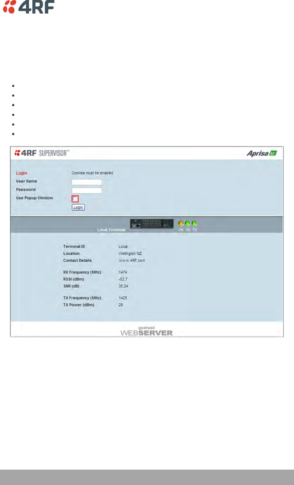
Managing the Terminal | 59
Aprisa XE User Manual
SuperVisor
The SuperVisor management software is pre-loaded into an integrated web-server within the terminal.
SuperVisor runs on any Java-enabled web browser.
You can use SuperVisor to:
display and configure terminal parameters
view the terminal alarms
monitor the performance and status of the link
upgrade the terminal software
save and load configuration files
save performance and error information to a log file
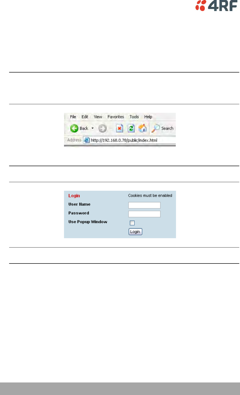
60 | Managing the Terminal
Aprisa XE User Manual
SuperVisor Logging In
The maximum number of concurrent users that can be logged into a terminal is 5.
If SuperVisor is inactive for a period of 30 minutes, the terminal will automatically log out the user.
To log in to SuperVisor:
1. Open your web browser and enter the IP address of the terminal.
Note: If you haven't yet assigned IP addresses to the terminals, use the factory-configured IP addresses
(see ‘Changing the Terminal’s IP Address’ on page 64).
If you don't know the IP address of the terminal, you can determine it using terminal emulation
software (see ‘To Get or Set the IP Address of a Terminal Using Setup’ on page 58).
2. Login with the user name and password assigned to you.
Note: If unique user names and passwords have not yet been configured, use the default user names
and passwords (see ‘Setting up users’ on page 65).
Important: After you login for the very first time, it is recommended that you change the default
admin password for security reasons (see ‘Changing passwords’ on page 67).
3. Tick the ‘Use Popup Window’ tick box if you want a separate browser window to launch after you have
logged in. The login page remains open in one window allowing you to view or configure settings in
another page. This is useful if you have more than one link to configure, for example, protected
terminals.
4. When you have logged in, the Summary page shows a summary of both the Local and Remote
terminals’ parameters.

Managing the Terminal | 61
Aprisa XE User Manual
SuperVisor Logging Out
As the maximum number of concurrent users that can be logged into a terminal is 5, not logging out
correctly can restrict access to the terminal until the after the timeout period (30 minutes).
Logging out from a terminal will logout all users logged in with the same user name.
If the SuperVisor window is closed without logging out, the terminal will automatically log the user out
after a timeout period of 30 minutes.
To log out of SuperVisor:
1. Click on the ‘Logout’ button on the Summary Bar.
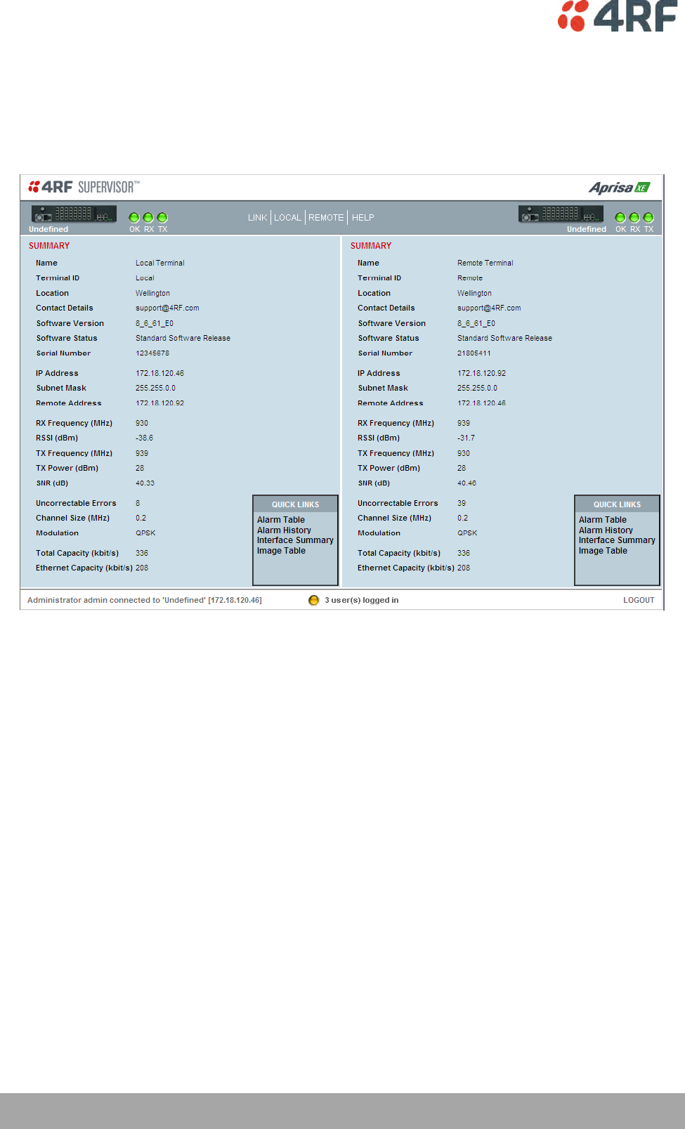
62 | Managing the Terminal
Aprisa XE User Manual
SuperVisor Main Screen
The SuperVisor Main Screen presents a summary of both the local and remote terminals and the status of
the terminal front panel LED indicators:
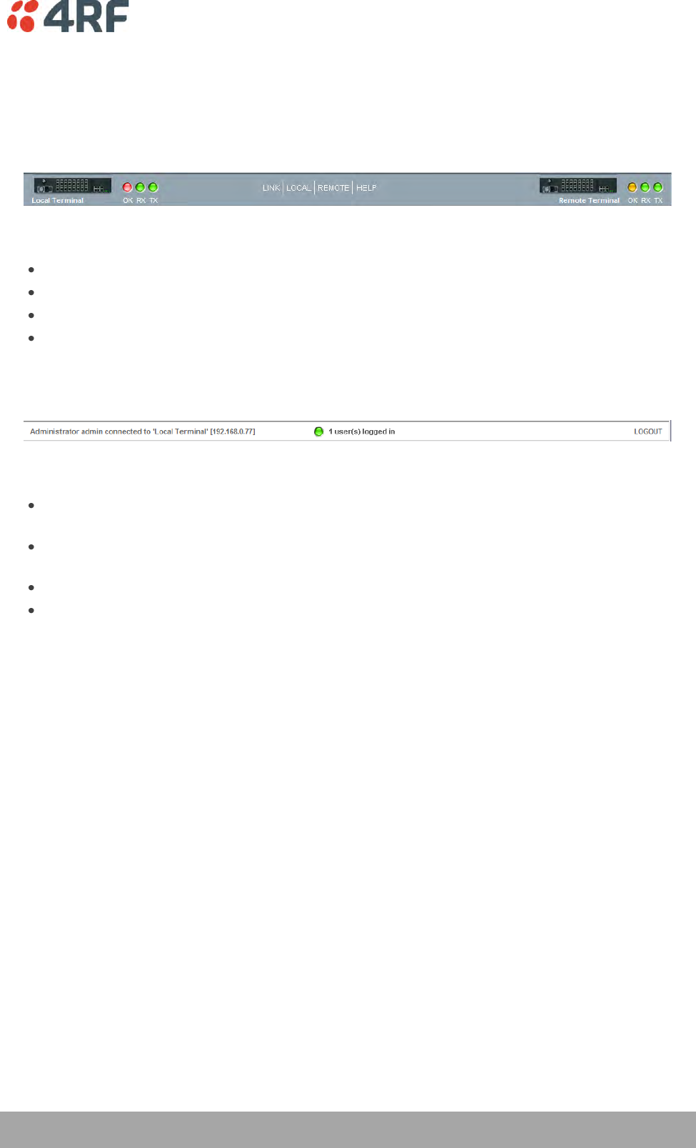
Managing the Terminal | 63
Aprisa XE User Manual
SuperVisor Menu Bar
The SuperVisor Menu Bar at the top of the screen shows the names of the terminals, the top level menus
and three status indicators for both the local and remote terminals. These indicators reflect the status
LED indicators on the front panel of terminal.
There are four menus available:
Link - menu options for both terminals in a link
Local - menu options for the local terminal in a link
Remote - menu options for the remote terminal in a link
Help - provides details about the terminal
SuperVisor Summary Bar
The SuperVisor Summary Bar at the bottom of the screen shows:
The login name of the person currently logged in together with the name of the local terminal and
its IP address.
A login alarm that indicating that someone else has logged into and could be working on the same
link. The LED is green for 1 user and yellow for more than 1 user.
The number of users logged in to the link
A SuperVisor logout button
64 | Managing the Terminal
Aprisa XE User Manual
Changing the Terminal’s IP Address
You can use SuperVisor to change the IP address of the terminal from the default. Alternatively, you can
assign the IP address using the SETUP port (see ‘To Get or Set the IP Address of a Terminal Using Setup’ on
page 58).
To change the IP address of the terminals using SuperVisor:
1. Launch your web browser and connect to the terminal using the one of the factory-configured default
IP addresses shown below:
Terminal
IP address
Unprotected terminals
Terminal 1 (local)
169.254.50.10
Terminal 2 (remote)
169.254.50.20
Protected terminals
Terminal 1, terminal A (local)
169.254.50.10
Terminal 1, terminal B (local)
169.254.50.11
Terminal 2, terminal A (remote)
169.254.50.20
Terminal 2, terminal B (remote)
169.254.50.21
Note: The factory default settings for the subnets is 255.255.0.0; the gateway is 0.0.0.0.
2. Log into the terminal as the administrator with the user name 'admin' and the password 'admin'.
Note: For security reasons, change the admin password (see ‘Changing passwords’ on page 67) as soon
as possible.
3. Select Link or Local or Remote > Terminal > Advanced and make the necessary changes.
Note: If this IP address change is being made over the RF link, it is important to change the far end of
the link first.
4. Once you have changed the IP address of a terminal, you must perform a hard reboot of the terminal
and then reconnect to it using the new IP address.
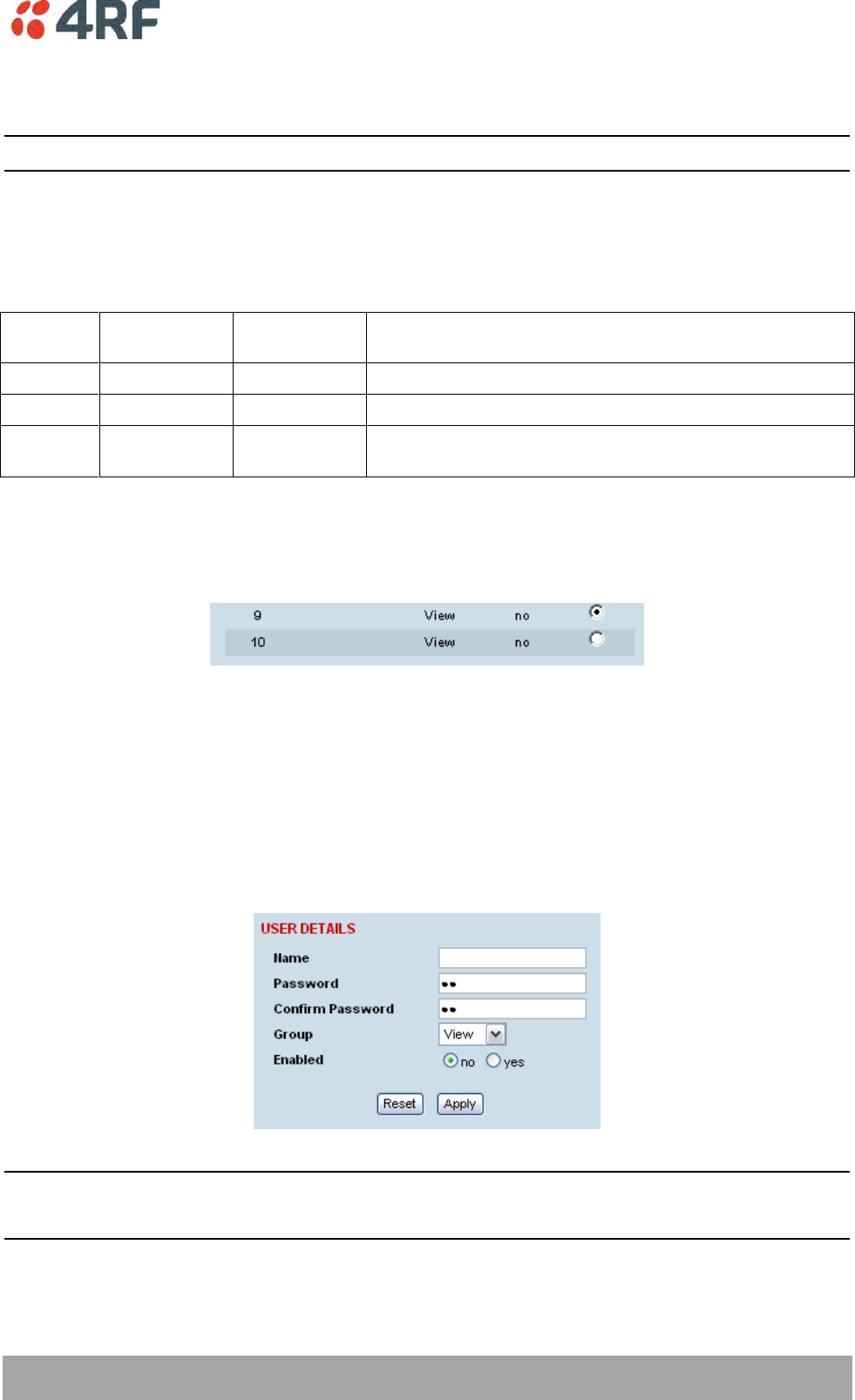
Managing the Terminal | 65
Aprisa XE User Manual
Setting Up Users
Note: You must login with 'admin' privileges to add, disable, delete a user or change a password.
User groups
There are three pre-defined user groups to allocate access rights to users. These user groups have
associated default user names and passwords of the same name.
User
Group
Default
User Name
Default
Password
Access Rights
View
view
view
Users in this group can only view terminal parameters.
Modify
modify
modify
Users in this group can view and edit terminal parameters.
Admin
admin
admin
Users in this group have full access to all terminal
parameters including the ability to add and change users.
Adding a User
1. Select Local or Remote > Maintenance > User Admin > User Table.
2. Select an empty line (that isn't allocated to an existing user) and then click Edit.
3. Enter the user name.
A user name can be up to 32 characters but cannot contain back slashes, forward slashes, spaces,
tabs, single or double quotes.
4. Enter the Password and the Confirm Password.
A password can be up to 32 characters but cannot contain back slashes, forward slashes, spaces, tabs,
single or double quotes.
5. Select the group that they will belong to (View, Modify, or Admin).
6. If the user requires immediate access, enable the user by clicking on Yes.
7. Click Apply.
Note 1: The new user must be setup on both the Local and Remote terminals.
Note 2: For the changes to take effect, you must reboot the terminal (Local > Maintenance > Reboot).
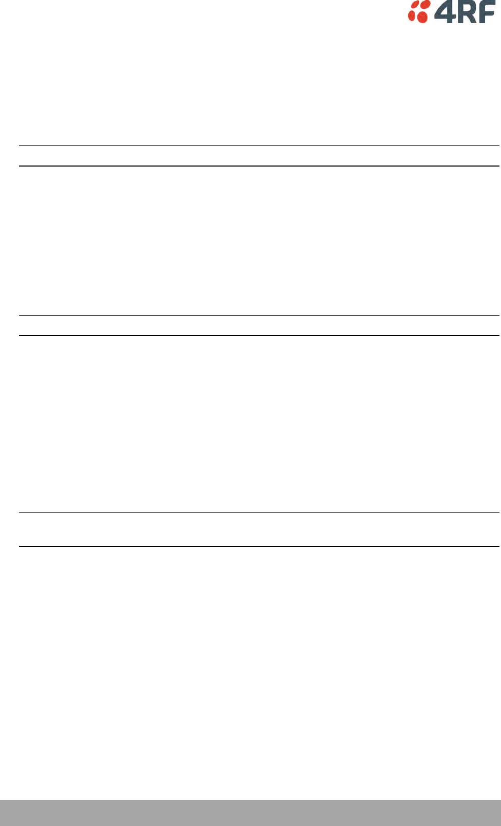
66 | Managing the Terminal
Aprisa XE User Manual
Disabling a User
1. Select Local or Remote > Maintenance > User Admin > User Table.
2. Select the user who you want to disable.
3. Click Edit to display the User details and set Enabled to 'No'.
4. When you have made your changes, click Apply to apply changes or Reset to restore the previous
configuration.
Note: For the changes to take effect, you must reboot the terminal (Local > Maintenance > Reboot).
Deleting a User
1. Select Local or Remote > Maintenance > User Admin > User Table.
2. Select the user you want to delete.
3. Click Edit to display the user details and delete the User Name and Password.
4. Reset the Group to 'View' and set Enabled to 'no'.
5. When you have made your changes, click Apply to apply changes or Reset to restore the previous
configuration.
Note: For the changes to take effect, you must reboot the terminal (Local > Maintenance > Reboot).
Saving User Information
You can save the list of users to your PC and then load this file to another terminal. This is useful if you
have multiple terminals to configure.
To save the user table to file:
1. Select Local > Maintenance > User Admin > Save User List.
2. Select the 'Save to disk' option in the dialog box that appears.
3. In the next dialog box that appears, navigate to the directory where you want to save the file, enter a
suitable filename, and then click Save (The default name for this file is 'downloadUsers').
Note: If this dialog box does not appear, change your Internet security settings to allow downloads.
You may also need to check your file download location setting.
To save the file to another terminal:
1. Select Local > Maintenance > User Admin > Load User List.
2. On the Upload Users page, select Browse and navigate to the file on your PC.
3. Click Apply.
The User Table appears and you can edit users, as required.
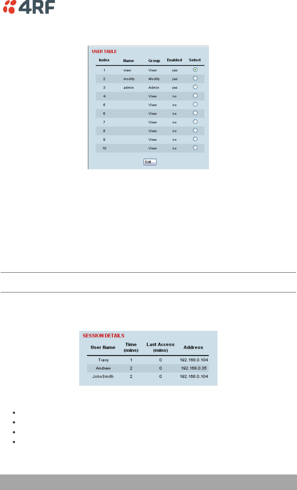
Managing the Terminal | 67
Aprisa XE User Manual
Changing Passwords
1. Select Local or Remote > Maintenance > User Admin > User Table.
2. Select the user whose password you want to change and click Edit.
3. Enter the new Password and the new Confirm Password.
A password can be up to 32 characters but cannot contain back slashes, forward slashes, spaces, tabs,
single or double quotes.
4. When you have made your changes, click Apply.
Viewing User Session Details
Administrators can check who is currently logged in, the computer they are logging in from, and how long
they have been logged in for.
Note: A 'session' is the period of time that begins when someone logs into the terminal and ends when
they logout.
To view user session details:
1. Select Local > Maintenance > User Admin > Session Details.
The 'Session Details' shows a list of the current users:
User Name: the User Name logged into the terminal.
Time: the number of minutes the user has been logged in.
Last Access: the number of minutes the user last accessed the terminal in this session.
Address: the address of the computer or proxy server address logged into the terminal.
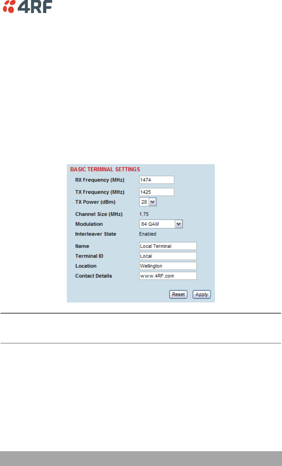
Configuring the Terminal | 69
Aprisa XE User Manual
8. Configuring the Terminal
Configuring the RF Settings
The RF settings are factory-configured before dispatch to the customer requirements. However, you can
change the RF settings, if required.
If two fundamental radio parameters (RX and TX frequency or modulation) are changed on the remote
terminal in the same apply action (simultaneously), the first parameter change could break the
communications link to the remote terminal and prevent the other commands from being actioned. There
is a two second delay between receiving the command and actioning it to allow for subsequent commands
to be received before the communications link is lost.
To configure RF settings:
Select Link or Local or Remote > Terminal > Basic:
Note: Transmit frequency, transmit power, channel size, modulation and antenna polarization would
normally be defined by a local regulatory body and licensed to a particular user.
Refer to your site license details when setting these fields.
70 | Configuring the Terminal
Aprisa XE User Manual
RX and TX Frequency
The local terminal transmit frequency must match the receive frequency of the remote terminal and the
remote terminal transmit frequency must match the receive frequency of the local terminal.
When setting the RX and TX frequency with SuperVisor, the frequency entered is automatically resolved to
the synthesizer step size for the terminal frequency band e.g. an ETSI 1400 MHz band frequency entry of
1474,010,000 Hz will be changed to 1474,012,500 Hz (see synthesizer step size in the table ‘Frequency
Bands’ on page 287).
The RX and TX frequency entered must be:
Within the frequency band limits of the chosen RF frequency band of the terminal as specified in
‘Frequency Bands’ on page 287. e.g. for an ETSI frequency band of 1400 MHz, the frequency band
limits are 1350 to 1550 MHz.
Within the TX / RX passband of the duplexer fitted in the terminal e.g. for a frequency band of
1400 MHz, the standard duplexer passband is 7 MHz and the TX / RX split is 48 MHz (see Duplexer
(bandpass) ‘Duplexers’ on page 301).
The duplexer passband and center frequencies are written on the duplexer label.
The TX and RX frequencies are validated against the duplexer parameters entered on SuperVisor Link or
Local or Remote > Terminal > Duplexer (see ‘Setting the Duplexer Parameters’ on page 79).
If the TX or RX frequency entered is not valid i.e. outside the operating range of the duplexer, a warning
message will popup. OK accepts the frequency entered and cancel rejects the frequency entered.
Important: Changing the remote terminal RX or TX frequency will disable all management communication
to the remote terminal but by changing the local terminal to match the remote terminal, the radio link
will be restored as will the management communication
BUT if the remote terminal RX or TX frequency is changed to be outside the operating range of the
terminal, changing the local terminal to match the remote terminal will not restore the radio link and all
management communication will be lost.
The remote terminal TX and RX frequencies cannot be changed simultaneously i.e. change one direction
and ‘Apply’ the change and then change the other direction and ‘Apply’ the change.
To change both TX and RX frequencies:
1. Change the remote terminal RX frequency and ‘Apply’ the change. The radio link will fail.
2. Change the local terminal TX frequency to that of the remote RX frequency and ‘Apply’ the change.
The radio link will restore.
3. Change the remote terminal TX frequency and ‘Apply’ the change. The radio link will fail.
4. Change the local terminal RX frequency to that of the remote TX frequency and ‘Apply’ the change.
The radio link will restore.
Transmit power
The transmitter power is the power measured at the duplexer output port.
The transmitter power adjustment range varies depending on the Modulation type and frequency band of
the terminal. For ETSI transmitter power range see ‘Transmitter Power ETSI’ on page 290.

Configuring the Terminal | 71
Aprisa XE User Manual
Channel size
The RF channel size is a factory-configured setting determined by the Aprisa XE hardware option.
Modulation
Both terminals must be set to the same modulation type.
When you change the modulation type in an operational terminal, traffic across the link will be
interrupted and you may need to change the cross connections capacity, as the Total Capacity of the radio
link may be exceeded.
Interleaver state
This Interleaver State displays the current state of the modem interleaver.
Interleaver State
Modem Interleaver Operation
Default
The modem interleaver is on for channel sizes of 250 kHz and greater
and off for channel sizes of 200 kHz and less.
Enabled
The modem interleaver is on.
Disabled
The modem interleaver is off.
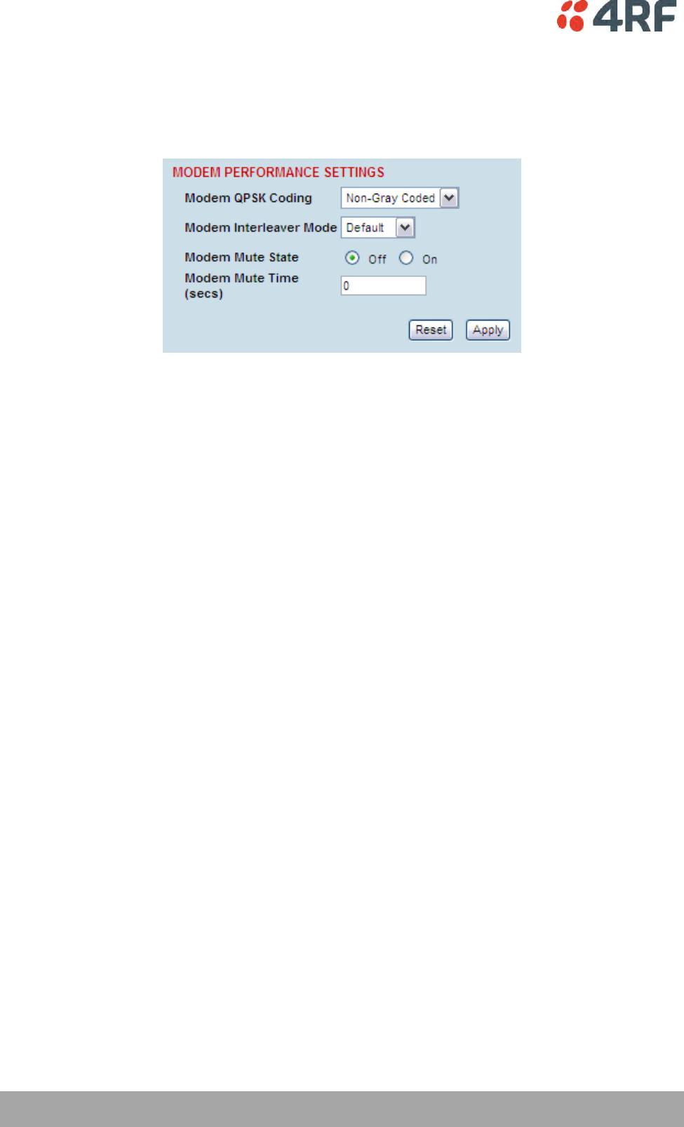
72 | Configuring the Terminal
Aprisa XE User Manual
Modem Performance Settings
To view or change the modem performance settings:
Select Link or Local or Remote > Terminal > Modem
Modem QPSK Coding
When the Modulation type is set to QPSK, the default QPSK Coding setting is ‘Non-Gray Coded’ but the
QPSK Coding can use ‘Gray Coded’ for interoperability with older hardware.
Modem Interleaver Mode
The Modem Interleaver improves modem bit error rate but increases the end to end link delay so the
Modem Interleaver should be enabled where a low bit error rate is required and disabled where a low end
to end link delay is required.
The ‘Default’ Modem Interleaver Mode setting is on for channel sizes of 250 kHz and greater and off for
channel sizes of 200 kHz and less. The specification of end to end link delay for both interleaver on and
off is given in the relevant RF Specification section. For ETSI Link Delays, see ‘Link Delays ETSI’ on page
292.
When you change the Modem Interleaver Mode in an operational terminal, traffic across the link will be
interrupted.
Both terminals must be set to the same Modem Interleaver Mode.
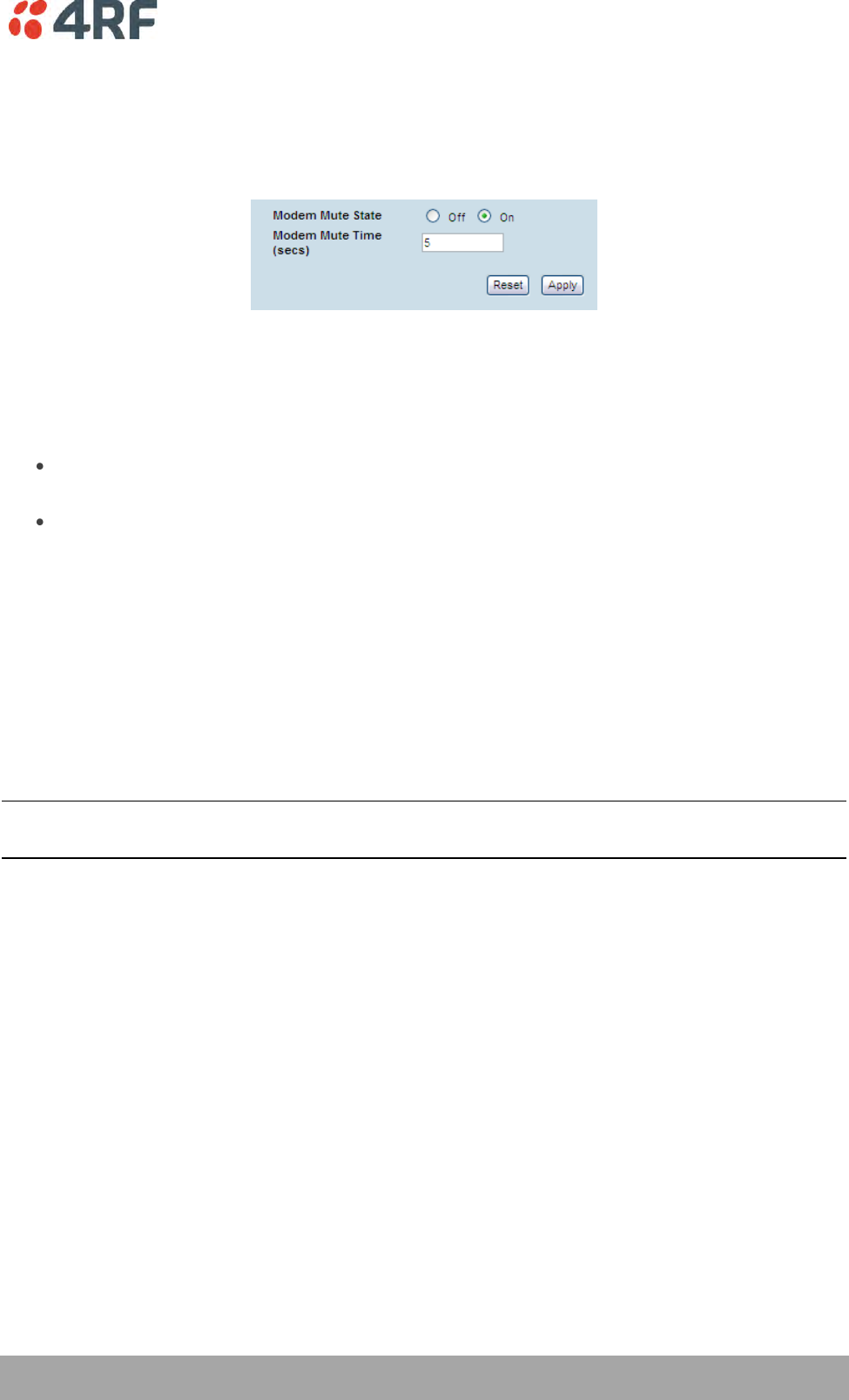
Configuring the Terminal | 73
Aprisa XE User Manual
Modem Mute Mode
The Aprisa XE radio always mutes its interface ports when the modem loses lock.
The Modem Mute feature mutes its interface ports when the modem Reed Solomon forward error
correction capability can no longer correct errors.
This can occur when the signal strength of the RF link reduces to within about 2 dB of the theoretical
sensitivity of the radio or when the radio is operating well above the sensitivity threshold but is in an
environment subject to impulse noise interference on the RF path.
When the mute activates;
On the analog cards, Q4EM, DFXS and DFXO, the audio path mutes and the signalling states go
idle.
On the digital cards, QV24 and HSS, it causes an all ones data pattern to be driven on the RXD
output line and handshake lines such as RTS / CTS to their off states while on the QJET card it
forces the ports to an AIS state.
The Modem Mute feature effectively reduces the radio receiver sensitivity by 2 to 3 dB from its published
values but will prevent errors from corrupting the tributary audio circuits.
Modem Mute Time
The Modem Mute Time determines the time the mute will persist after the last uncorrectable block is
received. This can be set from 0 to 10 seconds in 0.1 second steps.
Note: The Modem Mute feature is only available if the radio modem is Rev D or later. If the radio has a
Rev A, Rev B or Rev C modem, the modem mute functionality is not displayed in SuperVisor.
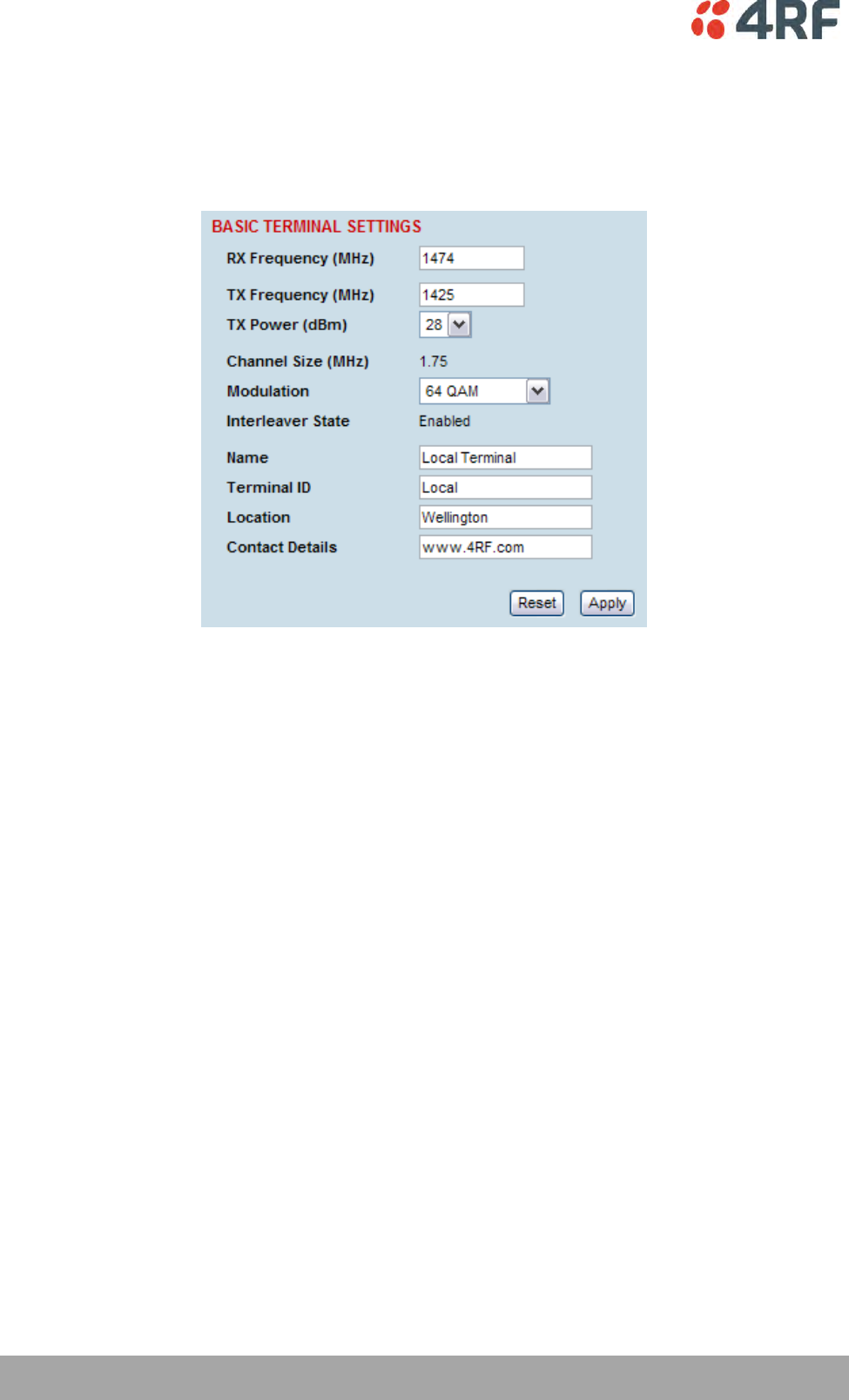
74 | Configuring the Terminal
Aprisa XE User Manual
Entering Basic Terminal Information
To enter basic terminal information:
Select Link or Local or Remote > Terminal > Basic
Terminal Information
The data entry in these four fields can be up to 40 characters but cannot contain back slashes or double
quotes.
1. Enter the terminal Name. This appears in the Terminal status and menu bar at the top of every page.
2. Enter a unique Terminal ID.
3. Enter the Location of the terminal.
4. Enter a contact name or an email address in Contact Details. The default value is ‘support@4RF.com’.
5. Click Apply to apply changes or Reset to restore the previous configuration.
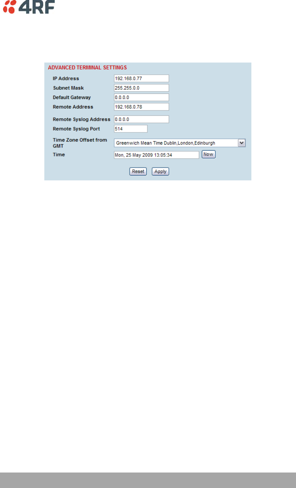
Configuring the Terminal | 75
Aprisa XE User Manual
Configuring the IP Settings
Select Link or Local or Remote > Terminal > Advanced.
Advanced Terminal Settings
1. Enter the static IP Address for the terminal assigned by your site network administrator using the
standard format xxx.xxx.xxx.xxx. The default IP address is in the range 169.254.50.xx.
2. Enter the Subnet Mask for the terminal using the standard format xxx.xxx.xxx.xxx. The default subnet
mask is 255.255.0.0.
3. Enter the Default Gateway for the terminal, if required, using the standard format xxx.xxx.xxx.xxx
(there is no default gateway set by default.)
4. Enter the IP address of the remote terminal using the standard format xxx.xxx.xxx.xxx (the default IP
address is in the range 169.254.50.xx.)
5. If you are setting up for remote logging (see ‘Setting up for Remote Logging’ on page 255), enter the
Syslog Address and the Syslog Port for the remote terminal.
6. In Time Zone Offset from GMT, select the time zone from the list (optional) .
7. To set the Time to the PC real-time clock, click Now.
8. Click Apply to apply changes or Reset to restore the previous configuration.
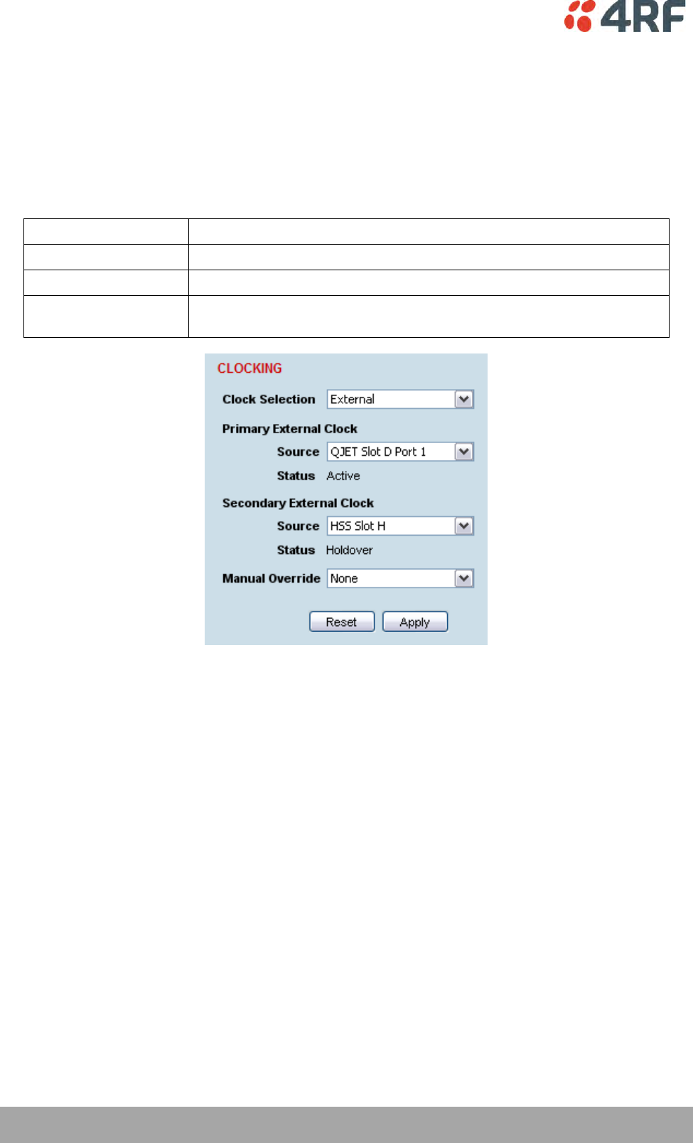
76 | Configuring the Terminal
Aprisa XE User Manual
Setting the Terminal Clocking
To view the terminal clock status:
Select Link or Local or Remote > Terminal > Clocking
The current selected clock source and the current status of the primary and secondary external clocks are
shown:
Clock Status
Clock Status Description
Inactive
This clock source is either not configured at all, or is not in current use
Active
This clock source is providing the clocking for the terminal
Holdover
This clock source is nominated as Primary or Secondary but is currently
unavailable.
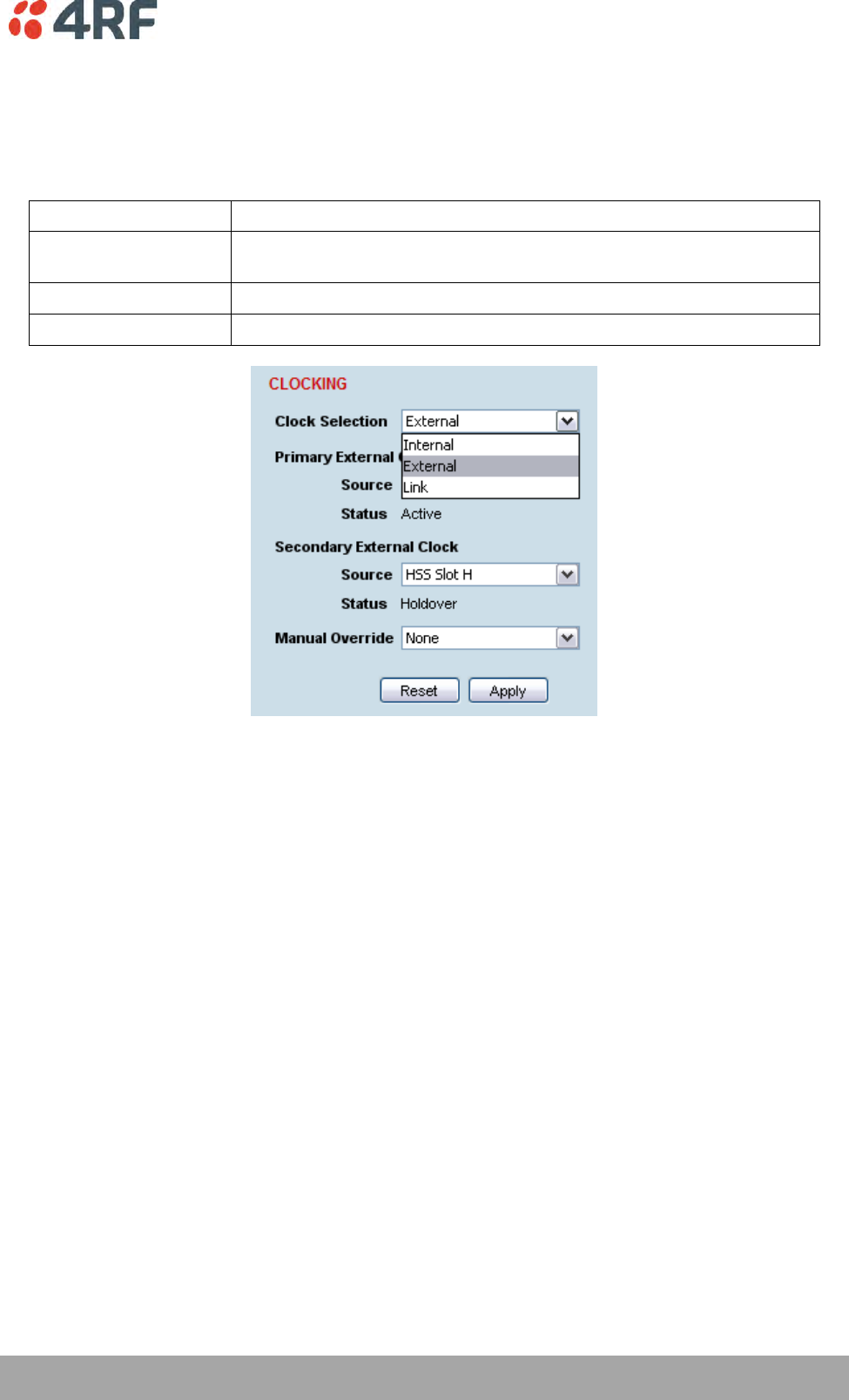
Configuring the Terminal | 77
Aprisa XE User Manual
To select the terminal clock source:
The Clock Source selected for the terminal will be used to clock all interface ports requiring clocking and
send a clocking signal over the RF link.
Select Link or Local or Remote > Terminal > Clocking > Clock Source and select one of the following:
Clock Source
Terminal Clocking
External
The terminal is clocked from the nominated interface port selected as
the primary external clock or the secondary external clock.
Internal
The terminal is clocked from the terminal's internal clock.
Link
The terminal is clocked from the RF link.
If the terminal Clock Source is set to External, the terminal will automatically clock from the nominated
primary external clock source if that clock source is available.
If the nominated primary external clock source is not available, the terminal will clock from the
nominated secondary external clock source if that clock source is available.
If the nominated secondary external clock source is not available, the terminal will clock from the internal
clock source.
When a nominated external clock source becomes available (primary or secondary), the terminal will then
clock from that clock source.
The terminal at one end of the link must have its clock source set to Internal or External and the terminal
at the other end of the link must have its clock source set to Link.
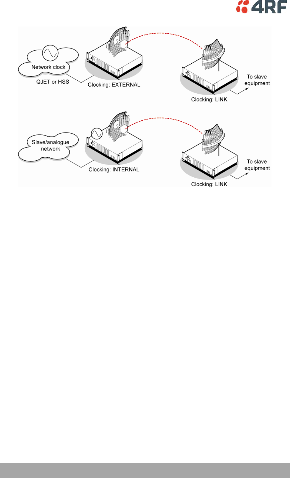
78 | Configuring the Terminal
Aprisa XE User Manual
To select the interface port for the external clock source (external clock source only):
Select the traffic interface ports nominated as Primary External Clock or Secondary External Clock
sources.
The failure of both External Clock sources results in a major alarm.
To manually override the automatic clock source selection (external clock source only):
Select either Switch to Primary or Switch to Secondary from the drop-down list, and click Apply.
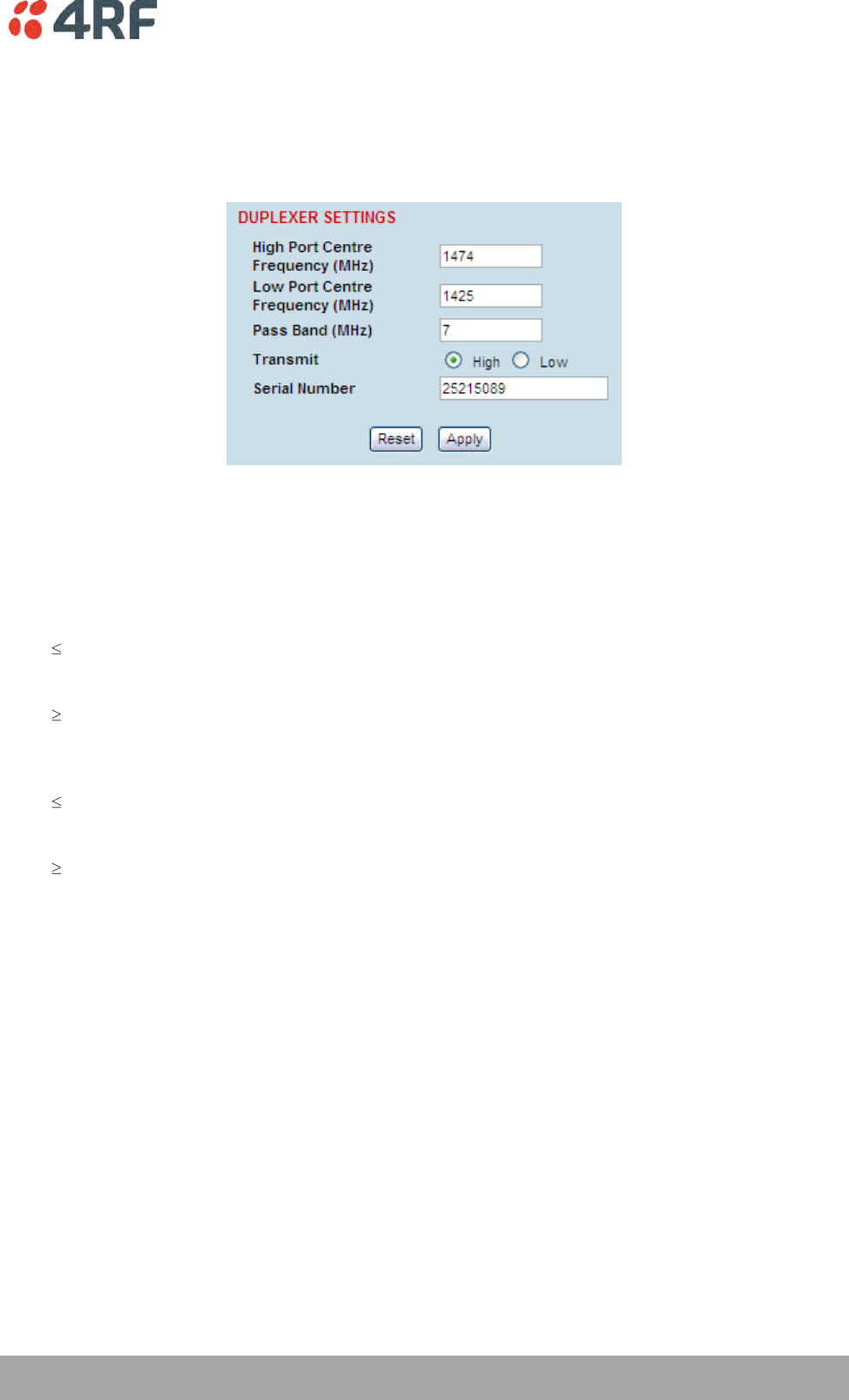
Configuring the Terminal | 79
Aprisa XE User Manual
Setting the Duplexer Parameters
To set the duplexer parameters:
Select Link or Local or Remote > Terminal > Duplexer
Duplexer Parameters
The terminal TX and RX frequencies entered are validated against the duplexer parameters entered on
this page.
A valid high port frequency must be:
(duplexer high port centre frequency + pass band/2 - channel size/2)
and
(duplexer high port centre frequency – pass band/2 + channel size/2)
A valid low port frequency must be:
(duplexer low port centre frequency + pass band/2 - channel size/2)
and
(duplexer low port centre frequency – pass band/2 + channel size/2)
The duplexer parameters are entered in the factory but can be re-entered if the duplexer is changed in
the field. The parameters required are shown on the duplexer label.
1. Enter the duplexer High port centre frequency and Low port centre frequency in MHz.
2. Enter the duplexer Pass band in MHz (the total passband e.g. if the duplexer passband is show as
± 3.5 MHz, the value entered is 7 MHz).
3. Select Transmit High or Transmit Low
Transmit High - the Transmitter is connected to the High Port of the duplexer.
Transmit Low - the Transmitter is connected to the Low Port of the duplexer.
4. Enter the duplexer Serial Number (used for record keeping only).
5. Click Apply to apply changes or Reset to restore the previous configuration.
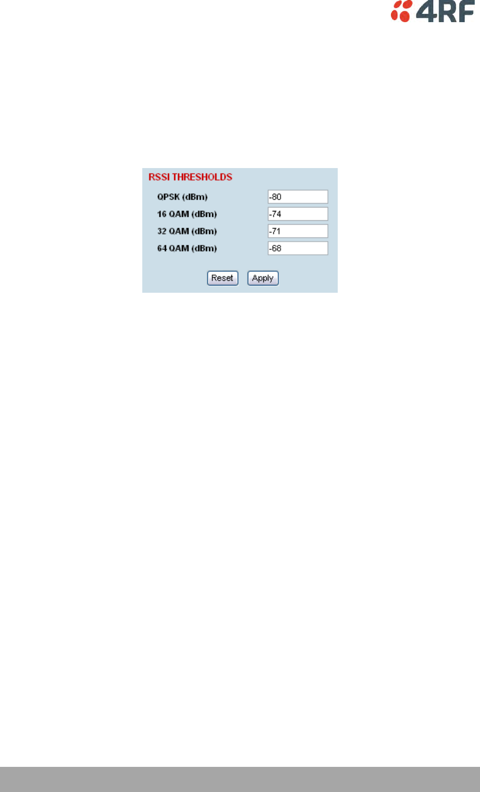
80 | Configuring the Terminal
Aprisa XE User Manual
Setting the RSSI Alarm Threshold
The threshold (in dB) at which the RSSI alarm activates can be set for each of the modulation types over
the adjustment range of -40 dBm to -110 dBm and the default values are as per the following screen shot.
The alarm threshold has a +1 dB hysteresis for the inactive state.
To set the RSSI alarm threshold:
Select Link or Local or Remote > Alarms > RSSI Thresholds
1. Enter the alarm threshold required for each of the modulation types.
2. Click Apply to apply changes or Reset to restore the previous configuration.
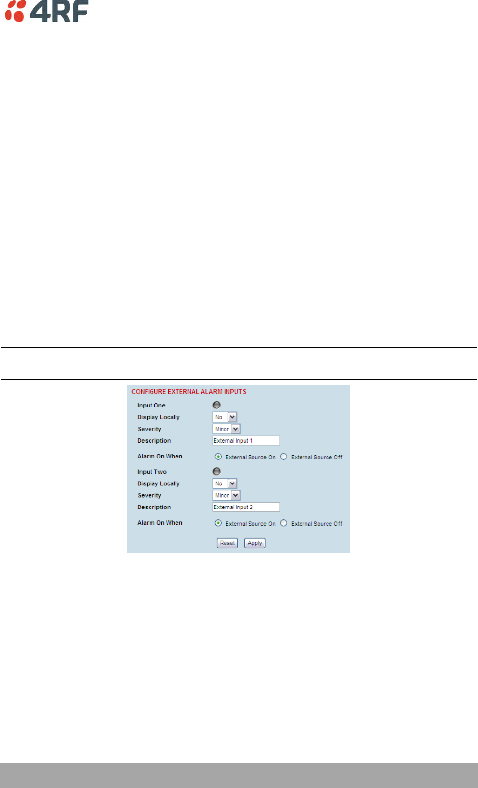
Configuring the Terminal | 81
Aprisa XE User Manual
Configuring the External Alarms
Each terminal has two external alarm inputs and four external alarm outputs, terminated on the ALARM
RJ-45 connector on the terminal front panel.
Each external alarm input can activate the Major / Minor terminal alarm or be mapped to a remote
terminal external alarm output.
The ‘Alarm On When’ (active alarm state) for both inputs can be configured for 'External Source On' or
'External Source Off' (default is External Source On).
Each external alarm output can be triggered by a local terminal Major / Minor alarm or a remote terminal
Major / Minor alarm or either of the remote external alarm inputs.
The ‘Relay Closed When’ for the four outputs can be configured for 'Alarm On' or 'Alarm Off' (default is
Alarm Off).
Configuring the External Alarm Inputs
To configure the External Alarm Inputs:
Select Link or Local or Remote > Alarms > Ext Alarm Inputs
Note: When the MHSB mode is enabled on the terminal, the external alarm input 2 is used for protection
switch control so is not available for user alarms.
The state of the local terminal external alarm input is always sent to the remote terminal and the
external alarm input can be mapped to a remote terminal external alarm output.
Alarms present on a local terminal external alarm input will only be displayed in the remote terminal
Alarm Table / Alarm History if it has been mapped to one of the remote terminal external alarm outputs.
82 | Configuring the Terminal
Aprisa XE User Manual
1. Select the Display Locally setting for each alarm input.
Display Locally
External Alarm Input Function
No
The external alarm input does not generate an alarm on the
local terminal, does not appear in the ‘Alarm Table’ or ‘Alarm
History’, and shows as grayed out on the ‘Alarm Summary’.
Default
Yes
The external alarm input generates an alarm on the local
terminal, displays in the ‘Alarm Table’ and ‘Alarm History’ and
the ‘Alarm Summary’.
2. Select the Severity setting for each alarm input.
This option is only relevant when the ‘Display Locally’ option is set to ‘Yes’.
Severity
External Alarm Input Severity
Minor
The external alarm input generates a minor alarm on the local
terminal.
Default
Major
The external alarm input generates a major alarm on the local
terminal.
3. Enter a Description for each alarm input. The default is ‘External Input 1’ / ‘External Input 2’.
4. Select the Alarm On When setting for each alarm input.
Alarm On When
External Alarm Input State
External Source On
The alarm is on (alarm active) when a source of voltage is
applied to the external alarm input and current is flowing.
Default
External Source Off
The alarm is on (alarm active) when no source of voltage is
applied to the external alarm input and hence no current is
flowing.
5. When you have made your changes, click Apply to apply changes or Reset to restore the previous
configuration.
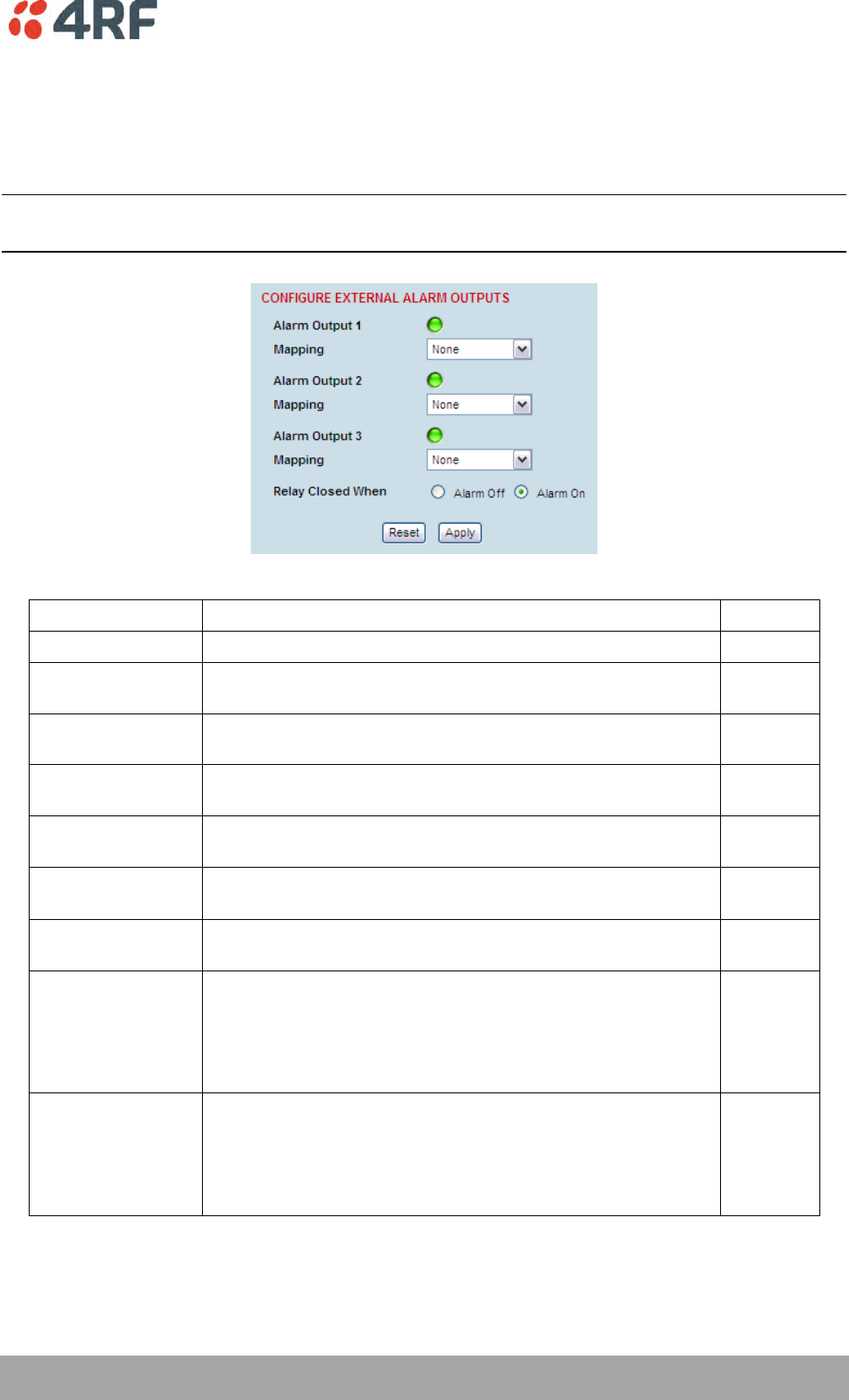
Configuring the Terminal | 83
Aprisa XE User Manual
Configuring the External Alarm Outputs
To configure the External Alarm Outputs:
Select Link or Local or Remote > Alarms > Ext Alarm Outputs
Note: When the MHSB mode is enabled on the terminal, the external alarm output 4 is used for protection
switch control so is not available for user alarms.
1. Select the Mapping required for each alarm output.
Mapping
External Alarm Output Function
None
No external alarm output.
Default
Local Major
The external alarm is present when the local terminal has a
major alarm.
Local Minor
The external alarm is present when the local terminal has a
minor alarm.
Remote Major
The external alarm is present when the remote terminal has a
major alarm.
Remote Minor
The external alarm is present when the remote terminal has a
minor alarm.
Remote Input 1
The external alarm is present when the remote terminal
external alarm input 1 is present.
Remote Input 2
The external alarm is present when the remote terminal
external alarm input 2 is present.
Test Major
External alarm test function – major alarm
This setting will output an alarm on the selected output but it
will not show in the alarm table or on the OK LED of the radio
(it is not a 'real' alarm).
This alarm test will clear if radio reboots.
Test Minor
External alarm test function – minor alarm
This setting will output an alarm on the selected output but it
will not show in the alarm table or on the OK LED of the radio
(it is not a 'real' alarm).
This alarm test will clear if radio reboots.

84 | Configuring the Terminal
Aprisa XE User Manual
2. Select the Relay closed when setting for the four alarm outputs.
Relay closed when
External Alarm Output State
Alarm on
When the external alarm output relay contact is closed, the
alarm is on (alarm active).
Default
Alarm off
When the external alarm output relay contact is closed, the
alarm is off (alarm inactive).
3. When you have made your changes, click Apply to apply changes or Reset to restore the previous
configuration.
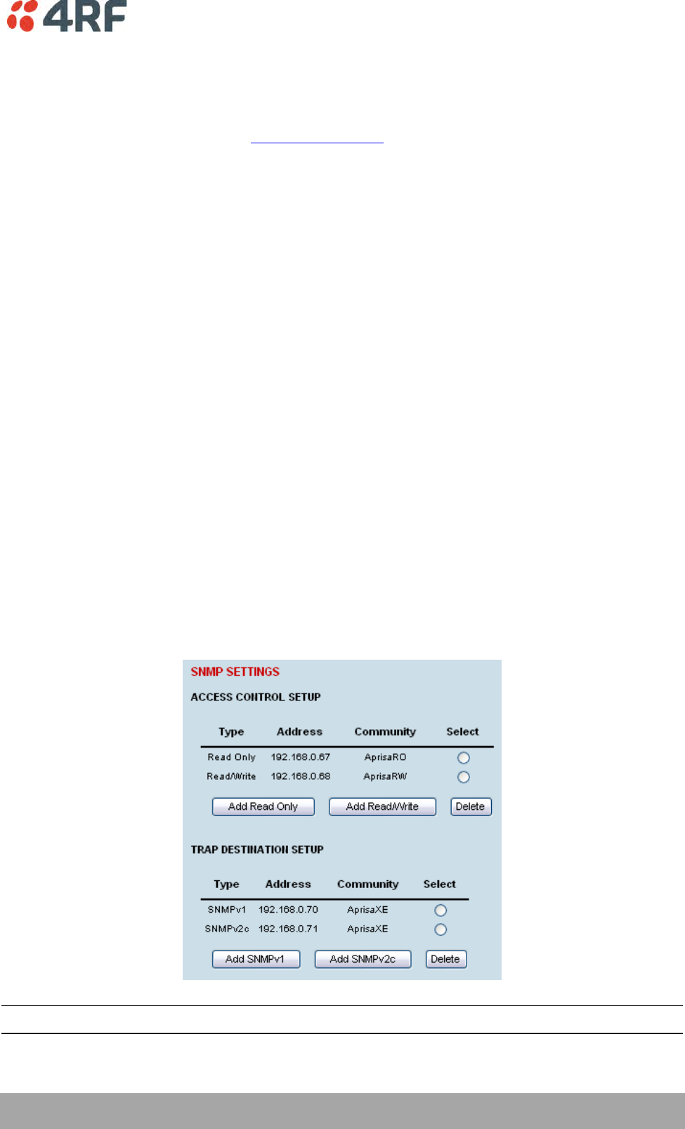
Configuring the Terminal | 85
Aprisa XE User Manual
Configuring SNMP Settings
In addition to web-based management (SuperVisor), the terminal can also be managed using the Simple
Network Management Protocol (SNMP). MIB files are supplied, and these can be used by a dedicated SNMP
Manager, such as Castle Rock's SNMPc (www.castlerock.com), to access most of the terminal's configurable
parameters.
However, it is recommended that SNMP is only used for status and alarm monitoring of your entire
network. SuperVisor is the best means to configure individual terminals.
For communication between the SNMP manager and the terminal, Access Controls, Trap Destinations, and
Community strings must be set up as described in the following sections.
A SNMP Access Control is the IP address of the terminal used by an SNMP manager or any other SNMP
device to access the terminal. Entering an IP address of ‘Any’ (not case sensitive) or * will allow any IP
address access to the terminal. A community string is sent with the IP address for security.
Commands are sent from the SNMP manager to the terminal to read or configure parameters of the
terminal e.g. setting of interface parameters.
A SNMP Trap Destination is the IP address of a station running an SNMP manager. A community string is
sent with the IP address for security.
Events are sent from the terminal to the SNMP manager e.g. alarm events.
A SNMP Community String is used to protect against unauthorized access (similar to a password). The
SNMP agent (terminal or SNMP manager) will check the community string before performing the task
requested in the SNMP message . Trap Destinations and Access Controls both use community strings for
protection.
To configure Trap Destinations and Access Controls:
Select Local > Maintenance > SNMP > SNMP Settings
Note: SNMP Settings can only be setup on the local terminal.
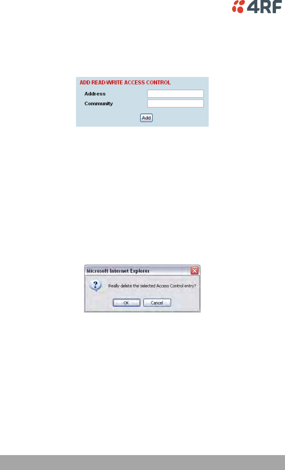
86 | Configuring the Terminal
Aprisa XE User Manual
SNMP Access Controls
To add an access control:
1. Click on the ‘Add Read Only’ button to enter a Read Only access control or click on the ‘Add
Read/Write’ button to enter a Read/Write access control.
2. Enter the IP address of each SNMP manager allowed access to the terminal (read/write access control
shown). The IP address entered must be a valid dot delimited IP address.
Entering an IP address of ‘Any’ or * will allow any IP address access to the terminal.
3. Enter the community string for the access control.
The Community string is usually different for Read Only and Read/Write operations.
There is no default 'public' community string for an access control, but a 'public' community string can
be entered which will have full MIB access, including the 4RF MIB.
4. Click Add.
To delete an access control:
1. Select the access control you want to delete and click Delete.
2. Click OK to delete the access control or Cancel to abort the delete.
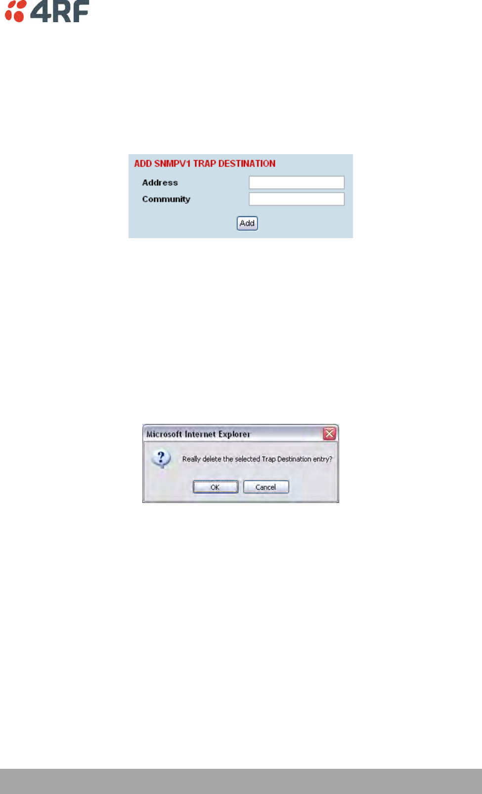
Configuring the Terminal | 87
Aprisa XE User Manual
SNMP Trap Destinations
To add a trap destination:
1. Click on the ‘Add SNMPv1’ button to enter a SNMPv1 trap destination or click on the ‘Add SNMPv2c’
button to enter a SNMPv2c trap destination.
The differences between SNMPv1 and SNMPv2c are concerned with the protocol operations that can be
performed. Selection of SNMPv1 and SNMPv2c must match the setup of the SNMP manager.
2. Enter the IP address of the server to which you want SNMP traps sent (SNMPv1 trap destination
shown). The IP address entered must be a valid dot delimited IP address.
3. Enter the community string for the trap destination.
There is no default 'public' community string for a trap destination, but a 'public' community string can
be entered.
4. Click Add.
To delete a trap destination:
1. Select the trap destination you want to delete and click Delete.
2. Click OK to delete the trap destination or Cancel to abort the delete.
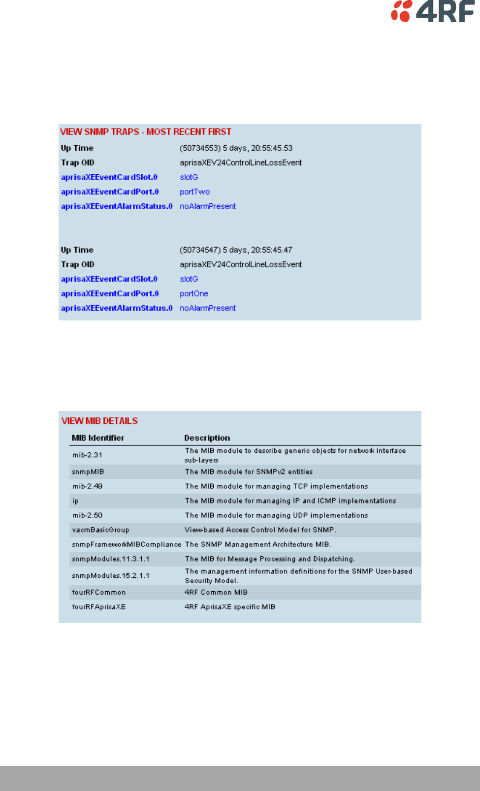
88 | Configuring the Terminal
Aprisa XE User Manual
Viewing the SNMP Traps
Any event or alarm in the SNMP objects list can be easily viewed. This also enables you to verify, if
required, that SNMP traps are being sent.
Select Local > Maintenance > SNMP > View Traps.
Viewing the SNMP MIB Details
This is useful to see what MIB (Management Information Base) objects the terminal supports.
Select Link or Local or Remote > Maintenance > SNMP > View MIB Details.
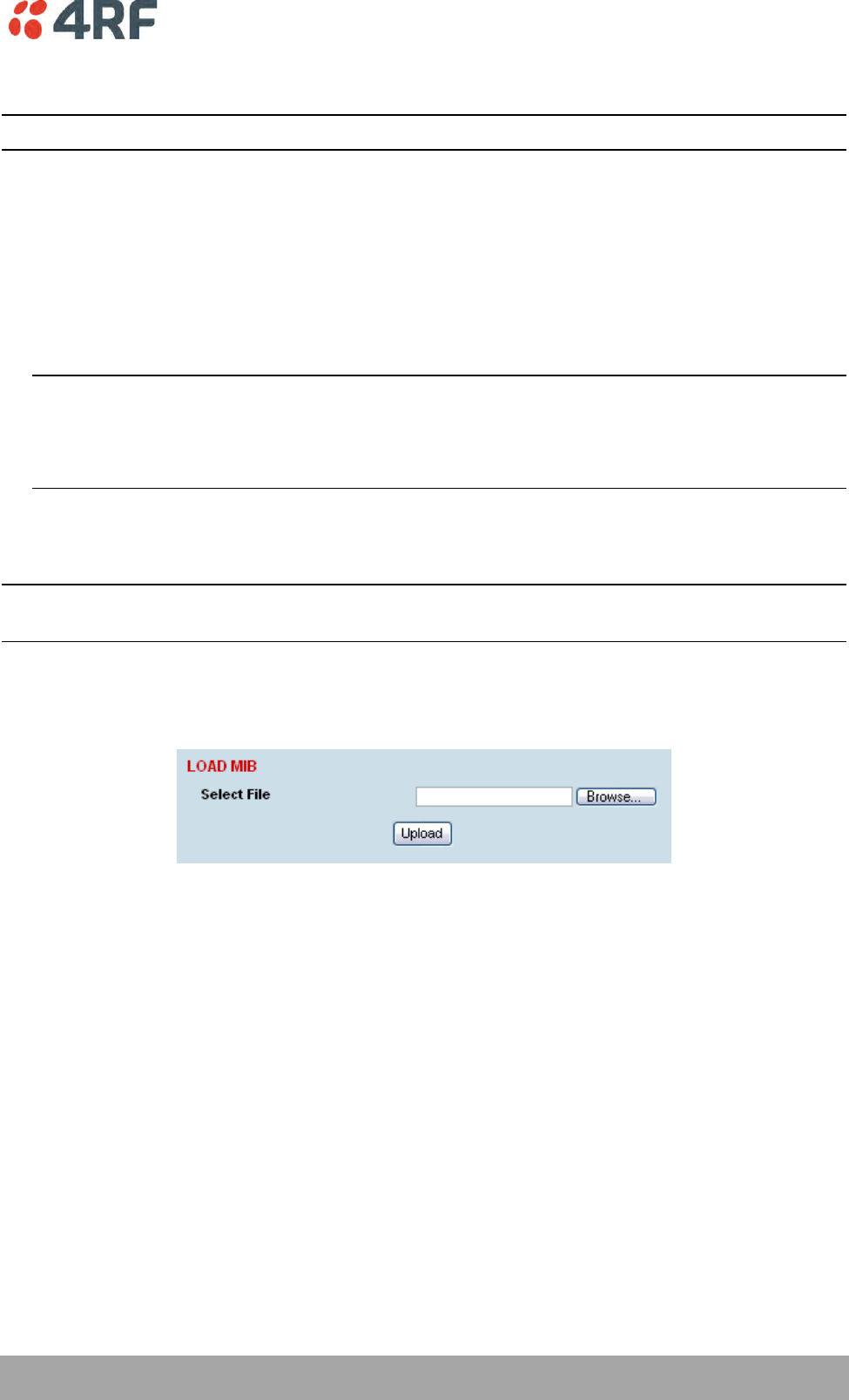
Configuring the Terminal | 89
Aprisa XE User Manual
Saving the Terminal's Configuration
Note: To save cross connection configurations, see page 155.
To save a configuration:
1. Ensure you are logged in with either 'modify' or 'admin' privileges.
2. Select Local > Maintenance > Config Files > Save MIB.
3. Select the 'Save to disk' option in the dialog box that appears.
4. In the next dialog box that appears, navigate to the directory where you want to save the file, enter a
suitable filename, and then click Save (The default name for this file is backupForm).
Note 1: If this dialog box does not appear, change your Internet security settings to allow downloads.
You may also need to check your default download location.
Note 2: Pop-ups must be enabled on you PC for this function to work (see ‘PC Settings for SuperVisor’
on page 50).
To load a configuration into a terminal:
Important: Only load a saved configuration file to another terminal that has exactly the same
configuration (RF variant and interface cards).
1. Ensure you are logged in with either 'modify' or 'admin' privileges.
2. Select Local or Remote > Maintenance > Config Files > Load MIB.
3. Click Browse and then navigate to the file and select it.
4. Click Upload to load the configuration file into the terminal.
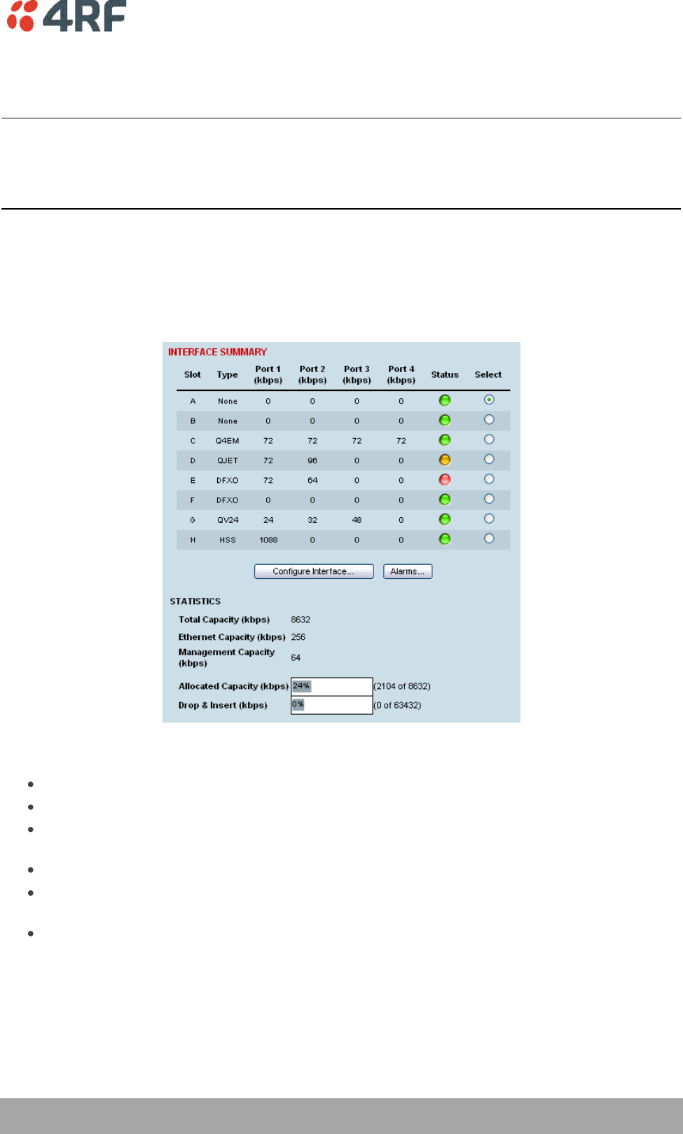
Configuring the Traffic Interfaces | 91
Aprisa XE User Manual
9. Configuring the Traffic Interfaces
Important: When configuring a link, it is important that you configure the remote terminal first as the
new configuration may break the management connection to the remote terminal.
Once the remote terminal has been configured, the local terminal should be configured to match the
remote terminal.
Viewing a Summary of the Interfaces
To view a summary of the interfaces fitted:
Select Link or Local or Remote > Interface > Interface Summary.
The Interface Summary page shows:
The interface type for each slot that has been configured with the capacity used by each port.
Total Capacity. The total capacity of the radio link.
Ethernet Capacity. The capacity allocated to the Ethernet traffic over the radio link. This includes
the user and management capacity assigned.
Management Capacity. The capacity allocated to the management conduit over ethernet.
Radio Capacity. The percentage of the total capacity of the radio link that has been allocated to
traffic interfaces.
Drop and insert capacity. The percentage of the total drop and insert capacity used for local drop
and insert cross connections. The total drop and insert capacity is 65536 kbit/s minus the assigned
radio link capacity.
Some interfaces also require extra bandwidth to be allocated to transport signalling, such as CTS / DTR
handshaking or E&M signals. The cross connections application automatically allocates capacity for
signalling when it is needed.

92 | Configuring the Traffic Interfaces
Aprisa XE User Manual
Configuring the Traffic Interfaces
Important: Before you can configure the traffic interfaces, the interface cards must be already installed
(see ‘Installing Interface Cards’ on page 235).
Configuring each traffic interface involves the following steps (specific instructions for each interface card
follow this page).
First, specify the port settings for the Remote terminal:
1. Select Remote > Interface > Interface Summary, select the interface card and click Configure
Interface.
2. Select the port you want to configure and modify the settings, as necessary.
3. Click Apply to save the changes you have made.
Now specify the port settings for the Local terminal:
1. Select Local > Interface > Interface Summary, select the interface card and click Configure Interface.
2. Select the port you want to configure and modify the settings, as necessary.
3. Click Apply to save the changes you have made.
Once you have done this, you will need to configure the traffic cross-connects (see ‘Configuring the traffic
cross connections’ on page 145) for each interface card.

Configuring the Traffic Interfaces | 93
Aprisa XE User Manual
Ethernet Switch
In the default mode, the Ethernet switch passes IP packets (up to 1522 bytes) as it receives them.
However, using SuperVisor you can configure VLAN, QoS and port speed settings to improve how IP traffic
is managed.
This is useful for operators who use virtual networks to segment different groups of users or different
types of traffic in their network. These groups can be maintained across the radio link thus ensuring users
in one virtual network cannot access data in other virtual networks.
The switch also has a high-speed address lookup engine, supporting up to 2048 preferential MAC addresses
as well as automatic learning and aging. Traffic is filtered through this table and only traffic destined for
the remote end is sent across the link improving bandwidth efficiency.
Note: You need ‘modify’ or ‘admin’ privileges to configure the Ethernet for VLAN and Quality of Service
(QoS).
VLAN tagging
By default, all user and management traffic is allocated the same VLAN across the link.
Alternatively, you can assign each of the four Ethernet ports to a VLAN. Each VLAN can be configured to
carry user traffic, or user traffic and radio management traffic. The VLAN tagging conforms to IEEE
802.1Q standard.
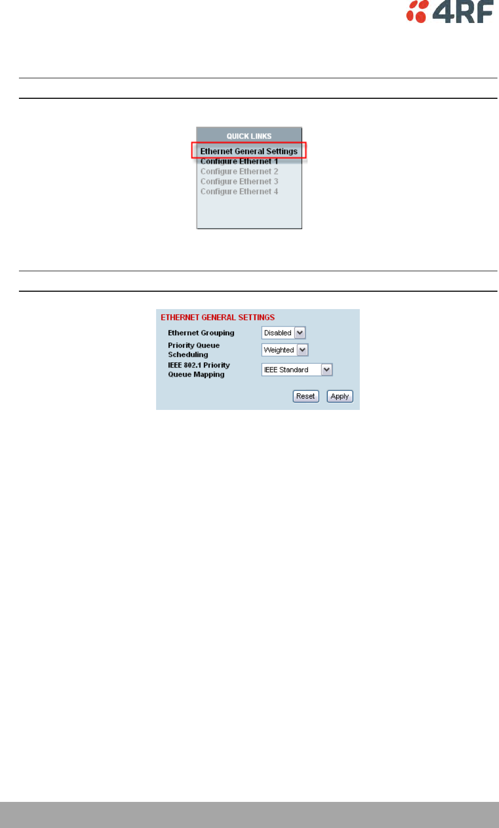
94 | Configuring the Traffic Interfaces
Aprisa XE User Manual
Configuring the Ethernet switch for VLAN tagging
1. Select Link or Local or Remote > Interface > Ethernet Settings.
Note: Always configure the remote terminal before the local terminal
2. In the Quick Links box at the bottom of the page, click Ethernet General Settings.
3. From Ethernet Grouping drop-down list select 'Enabled' ('Disabled' is the default setting; Ethernet
traffic is not segregated).
Important: Changing this setting will disrupt Ethernet traffic.
4. Click Apply to apply changes or Reset to restore the previous configuration.
You now need to select the VLAN groups for each of the four Ethernet ports.
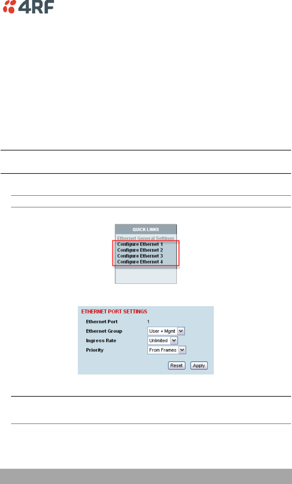
Configuring the Traffic Interfaces | 95
Aprisa XE User Manual
Specifying the VLAN ID for the Ethernet Ports
Each Ethernet port can be configured with one of five VLAN IDs. You can configure each of the physical
ports, numbered 1 to 4 with a VLAN ID (numbered User1 to User4 and User+Mgmt).
These VLAN IDs are applied at the ingress port and only used internally across the link. The VLAN ID is
removed when traffic exits the switch at the egress port. Data entering the Ethernet switch on ports 1 to 4
or the internal management port can only exit on ports that are associated with the same VLAN ID as the
ingress port.
For example, the physical RJ-45 port 1 may be on VLAN 3 at the local end, but at the remote end, the
physical RJ-45 port 4 may be associated with VLAN 3. Traffic entering the local end on port 1 will exit the
remote end on port 4.
To allow the radio link to transport traffic using existing VLAN ID information, the radio adds an extra
VLAN ID over the top of an existing VLAN ID (double-tagging). This extra VLAN ID is added at the ingress
port and removed at the egress port. This adds 4 bytes to the packet and the maximum packet size
supported by the radio is 1526 bytes.
Note 1: Tagged flows can only have one port per VLAN ID on each terminal.
Note 2: The ethernet switch only supports packets up to 1522 bytes in size at the ingress port.
1. Select Link or Local or Remote > Interface > Ethernet Settings.
Note: Always configure the remote terminal before the local terminal
2. In the Quick Links box at the bottom of the page, select the port you want to configure:
3. The Ethernet Port Settings page appears for the port you selected:
4. From the Ethernet Group drop-down list, select the VLAN group to which you want this port to belong.
Important: To access radio management traffic, you need to allocate one of the VLANs to ‘User and
Management’. It is strongly recommended that you indicate which port or group of ports is associated
to the management traffic first.
5. Click Apply.
6. Repeat steps 1-4 for the Ethernet switch in the other terminal in the link.
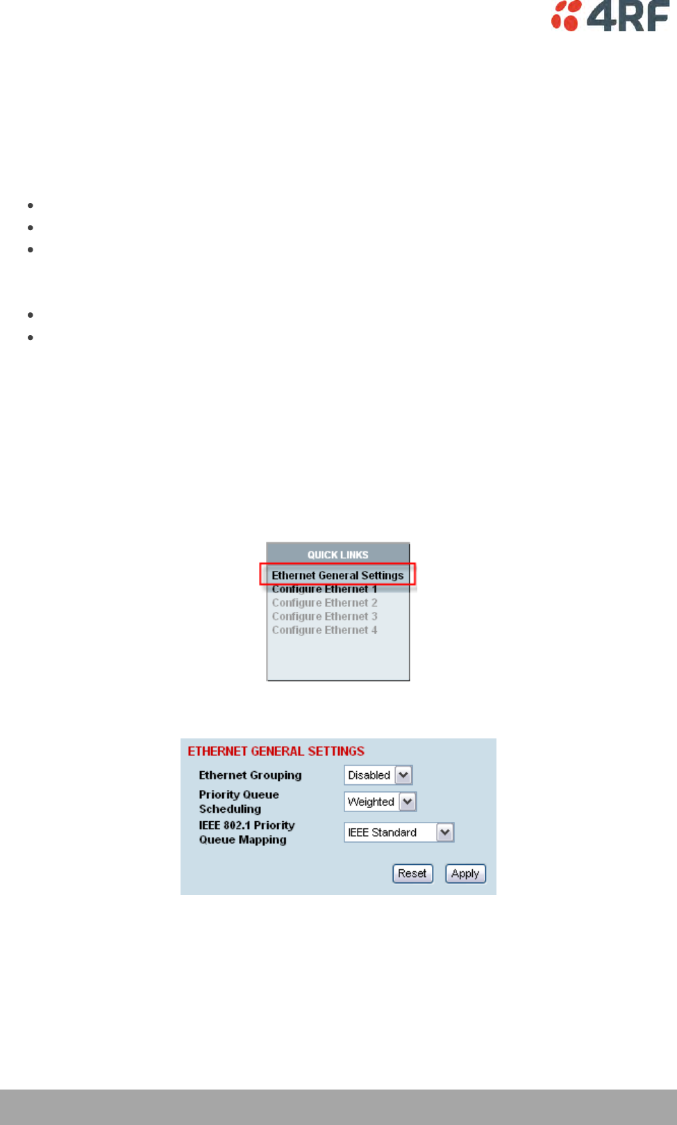
96 | Configuring the Traffic Interfaces
Aprisa XE User Manual
Quality of Service
Quality of Service (QoS) enables network operators to classify traffic passing through the Ethernet switch
into prioritized flows.
Each port can have a priority tag set at the ingress port, or it can be read directly from the Ethernet
traffic. When read directly from the Ethernet traffic, the following fields are used to determine the
traffic’s QoS priority.
The IEEE 802.1p Priority information in the IEEE 802.3ac Tag.
The IPv4 Type of Service field.
The IPv6 Traffic Class field.
You can select one of two queuing methods:
IEEE 802.1p standard method
Cisco-proprietary method
The queuing method determines how the traffic is prioritized.
Each port has four egress queues (queues 0-3) of differing priorities. Queue 0 is the lowest priority and
Queue 3 is the highest priority.
Configuring the Ethernet Switch for QoS
1. Select Link or Local or Remote > Interface > Ethernet Settings.
2. In the Quick Links box at the bottom of the page, click Ethernet General Settings.
The Ethernet General Settings page:
3. Leave Ethernet Grouping set to 'Disabled' (unless you want to enable VLAN tagging).
Configuring the Traffic Interfaces | 97
Aprisa XE User Manual
4. Select the Priority Queue Scheduling.
There are two methods for transmitting the Ethernet traffic queues across the link:
Strict: the queue is transmitted based on the priority. The first queue transmitted is the highest
priority queue and the terminal will not transmit any other traffic from any other queue until the
highest priority queue is empty. Then the next highest priority queue is transmitted, and so on.
Weighted (default): each of the queues will transmit a number of packets based on a weighting.
The following table shows how the weighting is applied to each queue.
Queue
Priority
Number of packets transmitted
Queue 3
Highest Priority
8 packets
Queue 2
4 packets
Queue 1
2 packets
Queue 0
Lowest Priority
1 packets
5. Select the IEEE 802.1 Priority Queue Mapping.
This determines the standard (or scheme) used for prioritizing traffic into one of four queues
numbered 0 to 3 (3 being the highest priority queue).
There are two possible methods for queuing the ethernet traffic. One is based on the IEEE 802.1D
standard (which is the default setting), and the other is based on the Cisco-proprietary method.
The following table shows how traffic is queued using the two methods:
Output Queue
Priority
Traffic Type
Cisco
Priority Queuing
IEEE 802.1D
Priority Queuing
0 (default)
Best Effort
0
1
1
Background
0
0
2
Spare
1
0
3
Excellent Effort
1
1
4
Controlled Load
2
2
5
‘Video’ < 100ms latency and jitter
2
2
6
‘Video’ < 10ms latency and jitter
3
3
7
Network Control
3
3
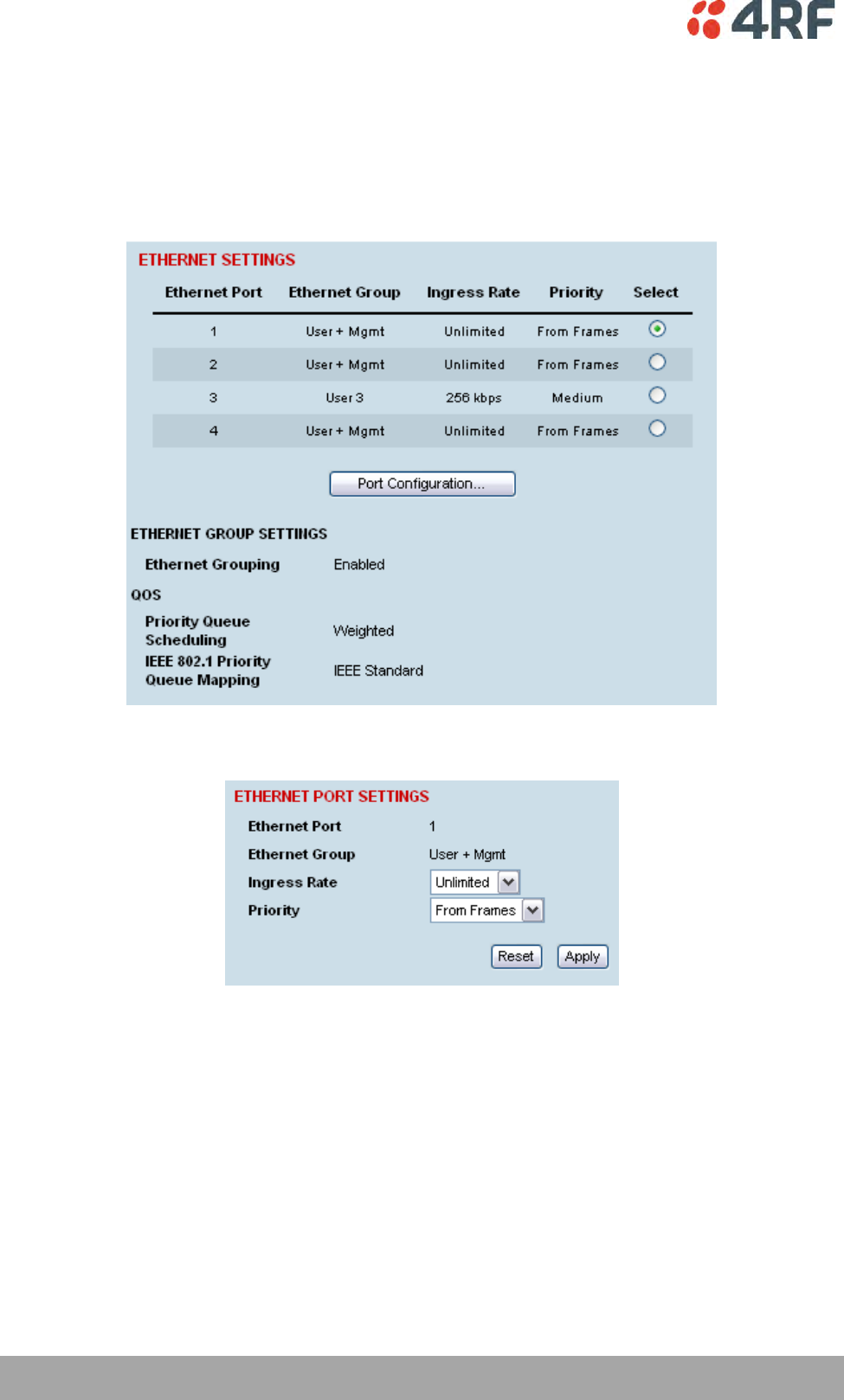
98 | Configuring the Traffic Interfaces
Aprisa XE User Manual
Configuring the Ethernet Ports for QoS
Each Ethernet port can be configured for Ingress Rates and Priority queues.
To configure the Ethernet ports for QoS:
1. Select Link or Local or Remote > Interface > Ethernet Settings.
2. Select the port you want to configure and click Port Configuration.

Configuring the Traffic Interfaces | 99
Aprisa XE User Manual
3. Select the required Ingress Rate for this port.
The ingress rate (input data rate) limits the rate that traffic is passed into the port. Operators can
protect the terminal’s traffic buffers against flooding by rate-limiting each port.
Ingress Rate
Unlimited
Default
128 kbit/s
256 kbit/s
512 kbit/s
1 Mbit/s
2 Mbit/s
4 Mbit/s
8 Mbit/s
4. Select the Priority for all Ethernet data entering this port.
The priority specifies where the priority control information is sourced from.
From Frames
Traffic is prioritized into one of the following traffic types (numbered 0 to 7) by the originating device
or application. Generally, the higher the priority, the higher the priority rating.
However, in the IEEE standard queuing scheme, the ordering of the priority is 1, 2, 0, 3, 4, 5, 6, 7. In
this case 0 has a higher priority than 1 and 2.
If priority control information is present in the Ethernet header, this information is used to priorities
the traffic but if there is no priority control information in the Ethernet header, the IP header is used
to priorities the traffic.
Low, Medium, High, Very High
The priority rating you select is applied to all traffic on the port and is applied to all traffic
irrespective of traffic type and the priority control information in the traffic.
5. Click Apply to apply changes or Reset to restore the previous configuration.
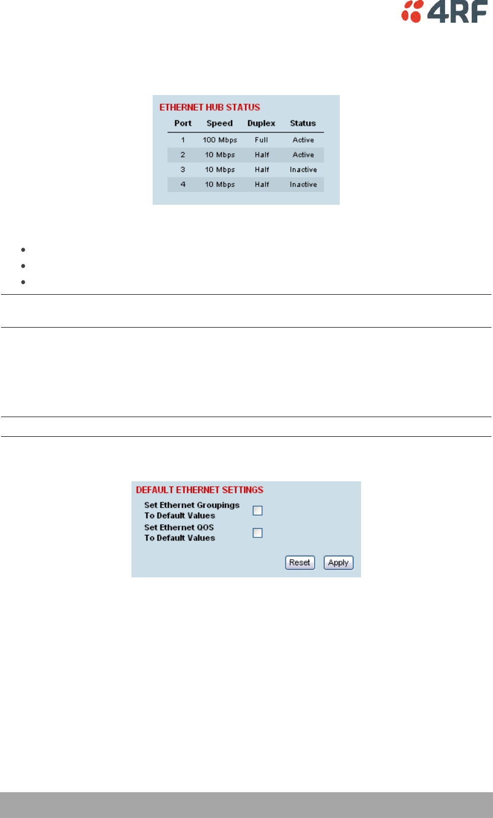
100 | Configuring the Traffic Interfaces
Aprisa XE User Manual
Viewing the Status of the Ethernet Ports
Select Link or Local or Remote > Interface > Switch Summary.
For each port the following is shown:
Speed — the data rate (in Mbit/s) of the port.
Duplex — whether half or full duplex.
Status — whether there is a cable plugged into the port (active) or not (inactive).
Note: The Ethernet ports on the terminal are set to auto-configure the speed and duplex for the best
performance.
Resetting the Ethernet Settings
You can easily reset the VLAN and QoS settings to the default values, if required. This is useful if you want
the Ethernet switch to operate in the default mode, that is, IP packets are passed across the link as
received.
Note: You can also do this using the Setup menu (see page 57.).
1. Select Link or Local or Remote > Interface > Default Ethernet Settings.
Set Ethernet Groupings To Default Values.
This resets the Ethernet Grouping setting to 'Disabled', which means that the Ethernet switch no
longer operates as a VLAN. In addition, all the Ethernet ports will default to the 'User and
Management' Ethernet Group.
Set Ethernet QoS To Default Values.
This resets the ingress rate for all the ports to 'Unlimited' and the priority to 'From Frames'. In
addition, the Ethernet QoS settings are reset to the defaults: Priority Queue Scheduling reverts to
'Weighted' and IEEE 802.1 Priority Queue Mapping reverts to 'IEEE Standard'.
2. Click Apply to apply changes or Reset to restore the previous configuration.
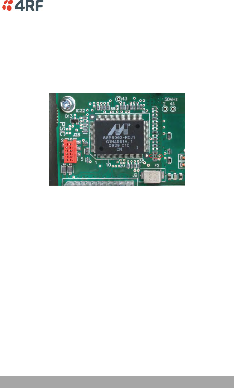
Configuring the Traffic Interfaces | 101
Aprisa XE User Manual
Ethernet Port Startup
In previous Aprisa XE software versions, the Ethernet switch ports where enabled when the radio powered
up.
In software version 8.6.53, the mode of operation was changed to disable the Ethernet switch ports until
the radio software has completed booting. This enhancement has been implemented to meet customer
requirements.
A hardware modification is required to the Aprisa XE motherboard to enable this enhancement (0 ohm
resistor fitted).
If the Aprisa XE motherboard hardware modification has been done, the Aprisa XE software version 8.6.53
or greater will be required to operate the radio. If Aprisa XE software prior to this version is used, the
Ethernet ports will not enable. For this reason, an Aprisa XE running software version 8.6.53 cannot be
downgraded to an earlier software version.
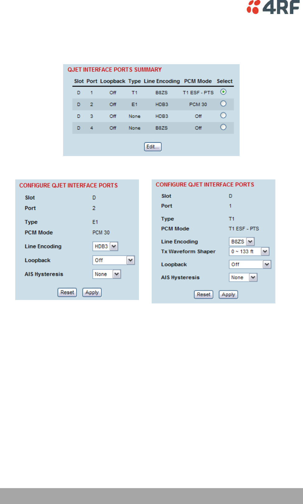
102 | Configuring the Traffic Interfaces
Aprisa XE User Manual
QJET Port Settings
1. Select Link or Local or Remote > Interface > Interface Summary, then select the QJET interface and
click Configure Interface.
2. Select the QJET port to be configured and click Edit.
3. Set the QJET Line Encoding:
For an E1 port, set the E1 Line Encoding as required to either HDB3 or AMI. The default is HDB3.
For a T1 port, set the T1 Line Encoding as required to either B8ZS or AMI. The default is B8ZS.
Configuring the Traffic Interfaces | 103
Aprisa XE User Manual
4. Set the QJET T1 Tx Waveform Shaper (T1 only).
The Tx Waveform Shaper applies 1/√f pre-emphasis to the transmit waveform to ensure the waveform
meets the G.703 pulse mask at the interconnect point. Waveform shaping assumes the use of 22 gauge
(0.32 mm2) twisted-pair cable. The default is 0 ~ 133 f t .
Cable Length Range
0 ~ 133 f t
Def au lt
133 ~ 266 f t
266 ~ 399 f t
399 ~ 533 f t
533 ~ 655 f t
5. Loopback controls the port loopbacks (see ‘Interface Loopbacks’ on page 242).
Setting
Function
Off
No port loopback
Line Facing
Port traffic from the customer is transmitted over the RF
link but is also looped back to the customer
Radio Facing
Traffic received from the RF link is passed to the customer
port but is also looped back to be transmitted over the RF
link
Note: The QJET E1 / T1 port green LED flashes when the loopback is active.
6. AIS Hysteresis sets the number of seconds after a Modem LOS that AIS is sent.
7. Click Apply to apply changes or Reset to restore the previous configuration.
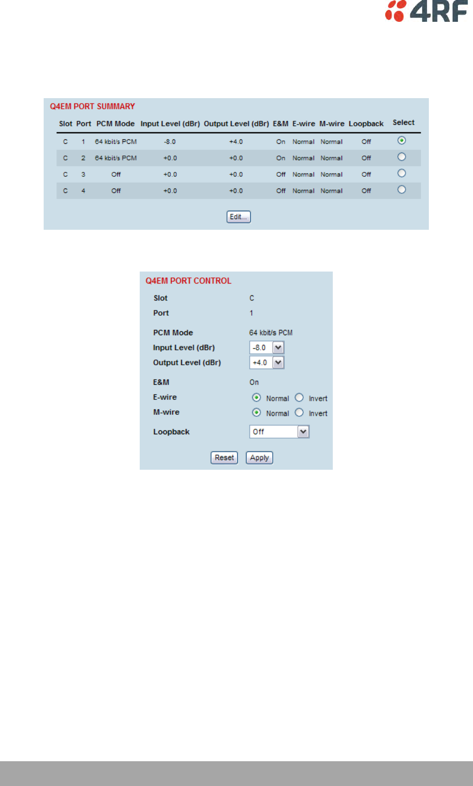
104 | Configuring the Traffic Interfaces
Aprisa XE User Manual
Q4EM Port Settings
1. Select Link or Local or Remote > Interface > Interface Summary, select the Q4EM interface, and click
Configure Interface.
2. Select the Q4EM port to be configured, and click Edit.
'Slot' shows the slot the Q4EM interface card is plugged into in the terminal (A – H).
'Port' shows the interface port number (1-4).
‘PCM Mode’ shows the current mode assigned to the port by the cross connect.
‘E&M’ shows if the E&M signalling on the port has been activated by the cross connect.
‘Loopback’ controls the 4 wire analogue port loopbacks.
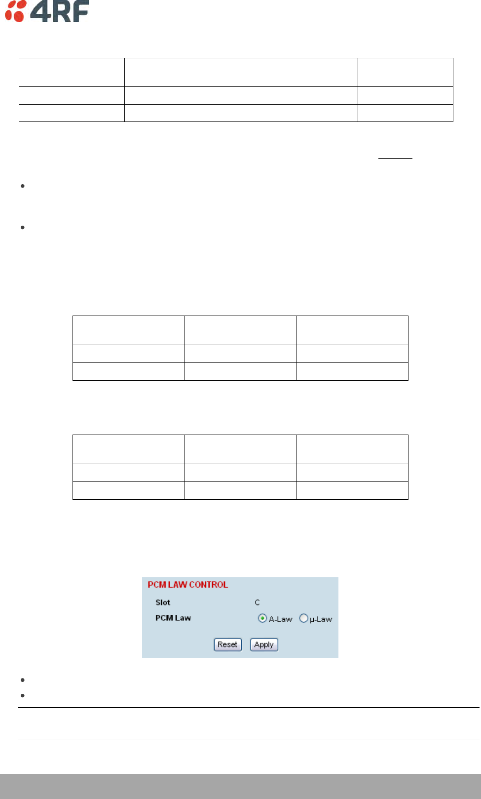
Configuring the Traffic Interfaces | 105
Aprisa XE User Manual
3. Set the Q4EM Output level and the Input level required.
Signal Direction
Level adjustment range
Default setting
Input level (Li)
-14.0 dBr to +4.0 dBr in 0.5 dB steps
+0.0 dBr
Output level (Lo)
-14.0 dBr to +4.0 dBr in 0.5 dB steps
+0.0 dBr
It is important that analogue signals presented from the Q4EM interface be normalized to fit within the ±
127 quantizing steps of the encoder. This is done by adjusting the circuit levels relative to the 0 dBm
(± 118 peak code) for example:
If a nominal input level of -6.0 dBm is applied to the Q4EM interface input port, the Q4EM Input
Level must be set to -6.0 dBr. This will effectively amplify the sent signal by 6.0 dB to produce a
digital signal with a ± 118 peak code (0 dBm).
If a nominal output level of -6.0 dBm is required from the Q4EM interface output port, the Q4EM
Output Level must be set to -6.0 dBr. This will effectively attenuate the received decoded signal
by 6 dB.
4. Set the Q4EM E wire interface to either Normal or Inverted.
This determines the state of the CAS bit relative to the state of the E wire:
E wire output
CAS bit Normal
(default)
CAS bit Inverted
Output Active
0
1
Output Inactive
1
0
5. Set the Q4EM M wire interface to either Normal or Inverted.
This determines the state of the CAS bit relative to the state of the M wire:
M wire input
CAS bit Normal
(default)
CAS bit Inverted
Input Active
0
1
Input Inactive
1
0
6. Click Apply to apply changes or Reset to restore the previous configuration.
7. Select Q4EM PCM Law Control from the Quick Links box.
This option sets the companding law used by the four ports on the Q4EM card.
A-Law is used internationally (default).
µ-Law is used in North America and Japan.
Note: The PCM Law Control controls all four ports on the Q4EM card. To run a mixture of µ-Law and A-
Law interfaces, multiple Q4EM cards are necessary.

106 | Configuring the Traffic Interfaces
Aprisa XE User Manual
8. Loopback controls the port loopbacks (see ‘Interface Loopbacks’ on page 242).
Setting
Function
Off
No port loopback
Line Facing
Port traffic from the customer is transmitted over the RF
link but is also looped back to the customer
Radio Facing
Traffic received from the RF link is passed to the customer
port but is also looped back to be transmitted over the RF
link

Configuring the Traffic Interfaces | 107
Aprisa XE User Manual
Loop Interface Circuits
DFXO / DFXS Loop Interface Circuits
Function
The function of DFXO / DFXS 2 wire loop interface circuits is to transparently extend the 2 wire interface
from the exchange line card to the telephone / PBX, ideally without loss or distortion.
The DFXO interface simulates the function of a telephone and a DFXS interface simulates the function of
an exchange line card. These circuits are known as ‘ring out, dial in’ 2 wire loop interface circuits.
Network Performance
The overall Network Performance is dependant on the number of D-A and A-D conversions and 2 wire to 4
wire / 4 wire to 2 wire conversions in the end to end circuit (telephone to telephone). To achieve the best
overall Network Performance, the number of D-A and A-D conversions and 2 wire to 4 wire / 4 wire to 2
wire conversions should be minimized.
Circuit Performance
The circuit quality achieved with a 2 wire voice circuit is very dependant on the external interface
parameters and the interconnecting copper line.
Short interconnecting copper lines (< 100 meters), have little effect on the circuit performance so the
interface parameters have the dominant affect on circuit performance.
As the length of the interconnecting copper line is increased, the attenuation of the analogue signal
degrades circuit performance but also the impedance of the copper line also has a greater effect on the
circuit performance. For this reason, complex line impedance networks (e.g. TBR21, TN12) were created
which model the average impedance of the copper network.
The factors that affect the quality of the circuit achieved are;
DFXO interface
The degree of match between the DFXO line termination impedance, the impedance of the
interconnecting copper line and the exchange line card line termination impedance. This affects
the return loss.
The degree of match between the DFXO line termination impedance, the impedance of the
interconnecting copper line and the exchange line card hybrid balance impedance. This affects
the exchange line card transhybrid balance.
The degree of match between the DFXO hybrid balance impedance, the impedance of the
interconnecting copper line and the exchange line card line termination impedance. This affects
the DFXO transhybrid balance.
The circuit levels of both the DFXO and the exchange line card.
DFXS interface
The degree of match between the DFXS line termination impedance, the impedance of the
interconnecting copper line and the telephone line termination impedance. This affects the return
loss.
The degree of match between the DFXS line termination impedance, the impedance of the
interconnecting copper line and the telephone hybrid balance impedance. This affects the
telephone transhybrid balance.
The degree of match between the DFXS hybrid balance impedance, the impedance of the
interconnecting copper line and the telephone line termination impedance. This affects the DFXS
transhybrid balance.
The circuit levels of both the DFXS and the telephone.

108 | Configuring the Traffic Interfaces
Aprisa XE User Manual
Line Termination Impedance
The line termination impedance (Zt) is the impedance seen looking into the DFXO or DFXS interface. The
line termination impedance is not the same as the hybrid balance impedance network (Zb) but can be set
to the same value.
Changing the DFXO / DFXS impedance setting on the Aprisa XE changes both the line termination
impedance and the hybrid balance impedance to the same value.
Hybrid Balance Impedance
The hybrid balance impedance (Zb) is the impedance network on the opposite side of the hybrid from the
DFXO / DFXS line interface. The purpose of this network is to balance the hybrid to the impedance
presented to the DFXO / DFXS line interface.
Changing the DFXO / DFXS impedance setting on the Aprisa XE changes both the line termination
impedance and the hybrid balance impedance to the same value.
Transhybrid loss
Transhybrid loss is a measure of how much analogue signal received from the remote terminal is passed
across the hybrid and sent to the remote terminal.
The transhybrid loss is maximized when the hybrid balance impedance matches the impedance presented
to the DFXO / DFXS line interface. An optimized hybrid minimizes circuit echo.
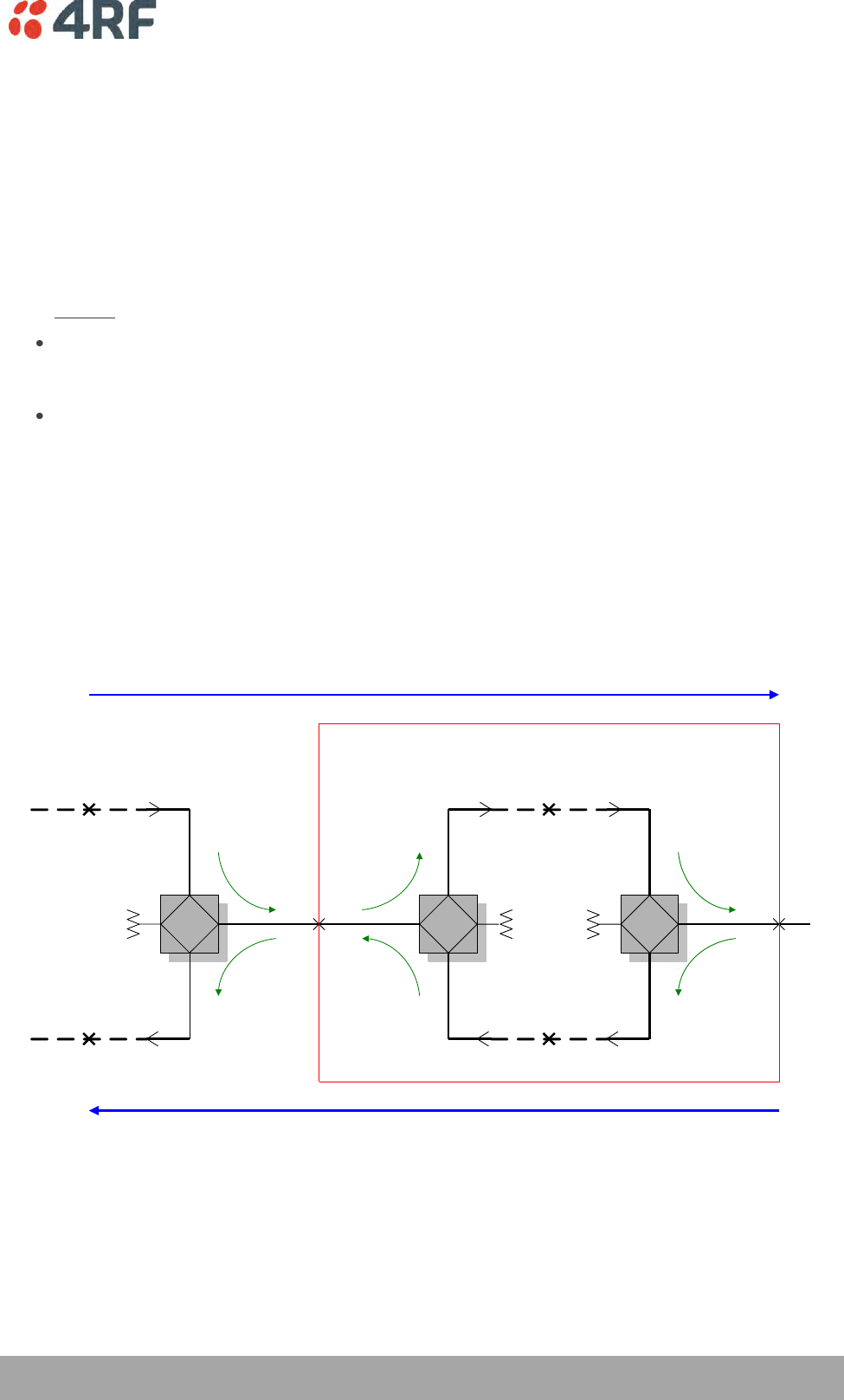
Configuring the Traffic Interfaces | 109
Aprisa XE User Manual
Circuit Levels
The 8 bit digital word for each analogue sample encoded (A law), has a maximum of 255 quantizing code
steps, a maximum of + 127 for positive signals and a minimum of - 127 for negative signals. No signal is
represented by the code step 0.
A nominal level of 0 dBm generates a peak code of ± 118 which allows up to + 3.14 dBm0 of headroom
before the maximum step of 127 is obtained. Any level greater than + 3.14 dBm0 will be distorted
(clipped) which will cause severe problems with analogue data transmission.
It is therefore important that analogue signals presented from the DFXO / DFXS line interface be
normalized to fit within the ± 127 quantizing steps of the encoder. This is done by adjusting the circuit
levels relative to the 0 dBm (± 118 peak code) for example:
If a nominal input level of +1 dBm is applied to the DFXS line interface, the DFXS Input Level must
be set to +1.0 dBr. This will effectively attenuate the sent signal by 1 dB to produce a digital
signal with a 118 peak code (0 dBm).
If a nominal output level of -6 dBm is required from the DFXS line interface, the DFXS Output Level
must be set to -6.0 dBr. This will effectively attenuate the received signal by 6 dB.
The circuit levels and the transhybrid loss of both ends of the circuit, also determine the stability of the
circuit. If the circuit levels are too high and the transhybrid loss figures achieved are too low, the circuit
can have a positive loop gain and can recirculate (sometimes called singing).
Typically, an end to end 2 wire voice circuit is engineered to have a 2-3 dB loss in both directions of
transmission.
2WS
2WR 2WS input
2WR output
0 dBr -6.0 dBr
+1.0 dBr
-8.0 dBm
+1.0 dBm
-2.0 dBm
0 dBr
0.0 dBm
-4.0 dBr
-1.0 dBr
-6.0 dBm
DFXS
Interface
DFXO
Interface
2WS
2WR
-6.0 dBr
+1.0 dBr
-1.0 dBm
0 dBr
0.0 dBm
0 dBr
-2.0 dBm
Exchange
Line Card
Aprisa XE
Overall Loss
= 3.0 dB
Overall Loss
= 8.0 dB
Derived System Level Plan
Note 1: The derived system loss is 2 dB in both directions due to the deliberate 2 dB level mismatch between
the exchange line card and the DFXO interface unit
ZBZB
ZB
Transmission
Reference Point
4WR
4WS4WR
4WS4WR
4WS
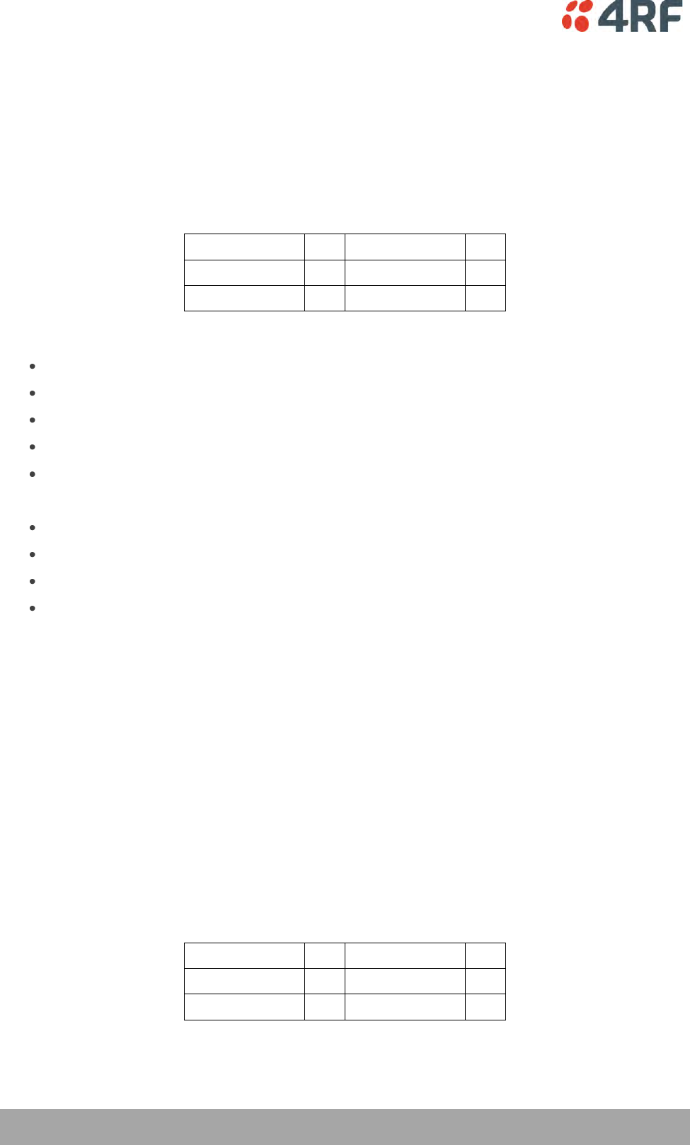
110 | Configuring the Traffic Interfaces
Aprisa XE User Manual
E1 CAS to DFXS Circuits
Function
E1 CAS to DFXS circuits can be provisioned over an Aprisa XE link by using a DFXS interface card at the
customer end of the link and a QJET at the exchange end of the link. The QJET E1 interface connects to
an exchange or PBX Digital Trunk Interface (DTI) to provide FXS foreign exchange circuits.
The Aprisa XE can interconnect at E1 to an exchange / PBX DTI if the DTI is capable of providing standard
1 bit channel associated signalling (CAS).
Forward
Af
Backward
Ab
Idle
1
Idle
1
Ringing
0
Loop (Off hook)
0
The signalling functions provided with a 1 bit CAS protocol are:
Ring cadence transmission
Ring trip
Off hook
Switch hook flash
Decadic dialling
The speech path functions as normal and provides:
Transmission of tones (e.g. dial tone, ring tone)
Caller ID
DTMF dialling
Speech
Setup
Cross connect the voice channel between the QJET and the DFXS card.
Cross connect the signalling (A bit only) using ‘4 wire compatible’ mode between the QJET and the DFXS
card.
Configure the E1 spare CAS bits to be compatible with the DTI (see ‘QJET Spare CAS Bit Control’ on page
165). The standard spare bit states are B = 1, C = 0, D = 1.
DFXS to DFXS Hotline Circuits
Function
A ‘Hotline’ circuit can be provisioned over an Aprisa XE link by using a DFXS interface card at both ends of
the link. When one phone goes off hook, the other phone rings and vice versa.
A 1 bit CAS protocol is used to signal between the DFXS interfaces:
Forward
Af
Backward
Ab
Idle
1
Idle
1
Ringing
0
Loop (Off hook)
0
Setup

Configuring the Traffic Interfaces | 111
Aprisa XE User Manual
Cross connect the voice channel on both DFXS cards.
Cross connect the signalling (A bit only) using ‘4 wire compatible’ mode on both DFXS cards.
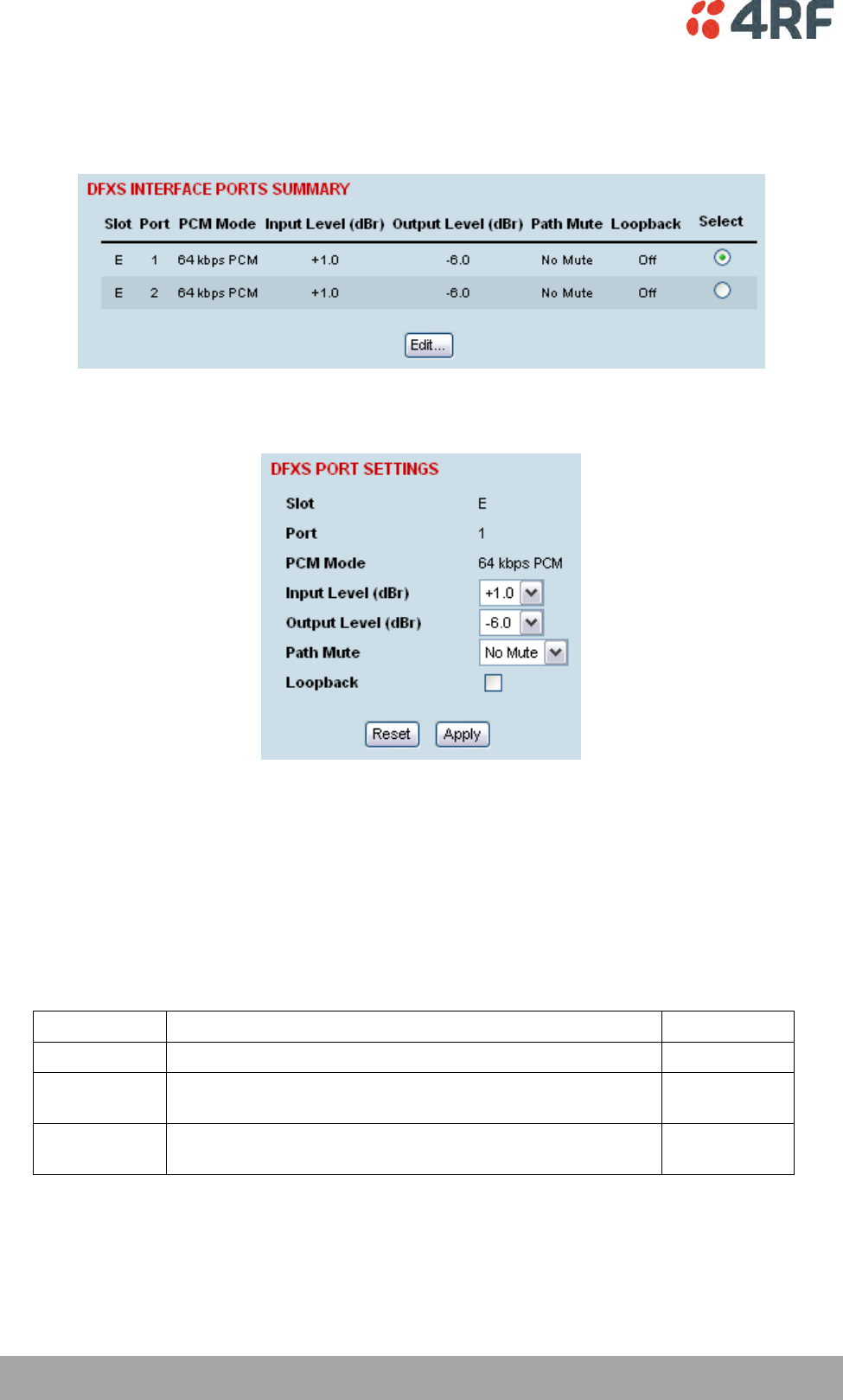
112 | Configuring the Traffic Interfaces
Aprisa XE User Manual
DFXS Port Settings
1. Select Link or Local or Remote > Interface > Interface Summary, then select the DFXS interface and
click Configure Interface.
2. Select the DFXS port to configure, and click Edit.
'Slot' shows the slot the DFXS interface card is plugged into in the terminal (A – H).
'Port' shows the interface port number (1-2).
‘PCM Mode’ shows the current mode assigned to the port by the cross connect.
‘Loopback’ loops back the port digital paths to return the port analogue signal back to the customer.
‘Path Mute’ mutes the TX or RX digital path. This function is used to mute the return direction of
transmission during A-A intrinsic performance testing as recommended in ITU G.712 para 1.2 Port
definitions.
Path Mute
Description
No Mute
Normal signal transmission in both directions
Default
Mute TX
Mutes the transmit digital path i.e. the signal from the DFXS
to the DFXO is muted
Mute RX
Mutes the receive digital path i.e. the signal from the DFXO
to the DFXS is muted
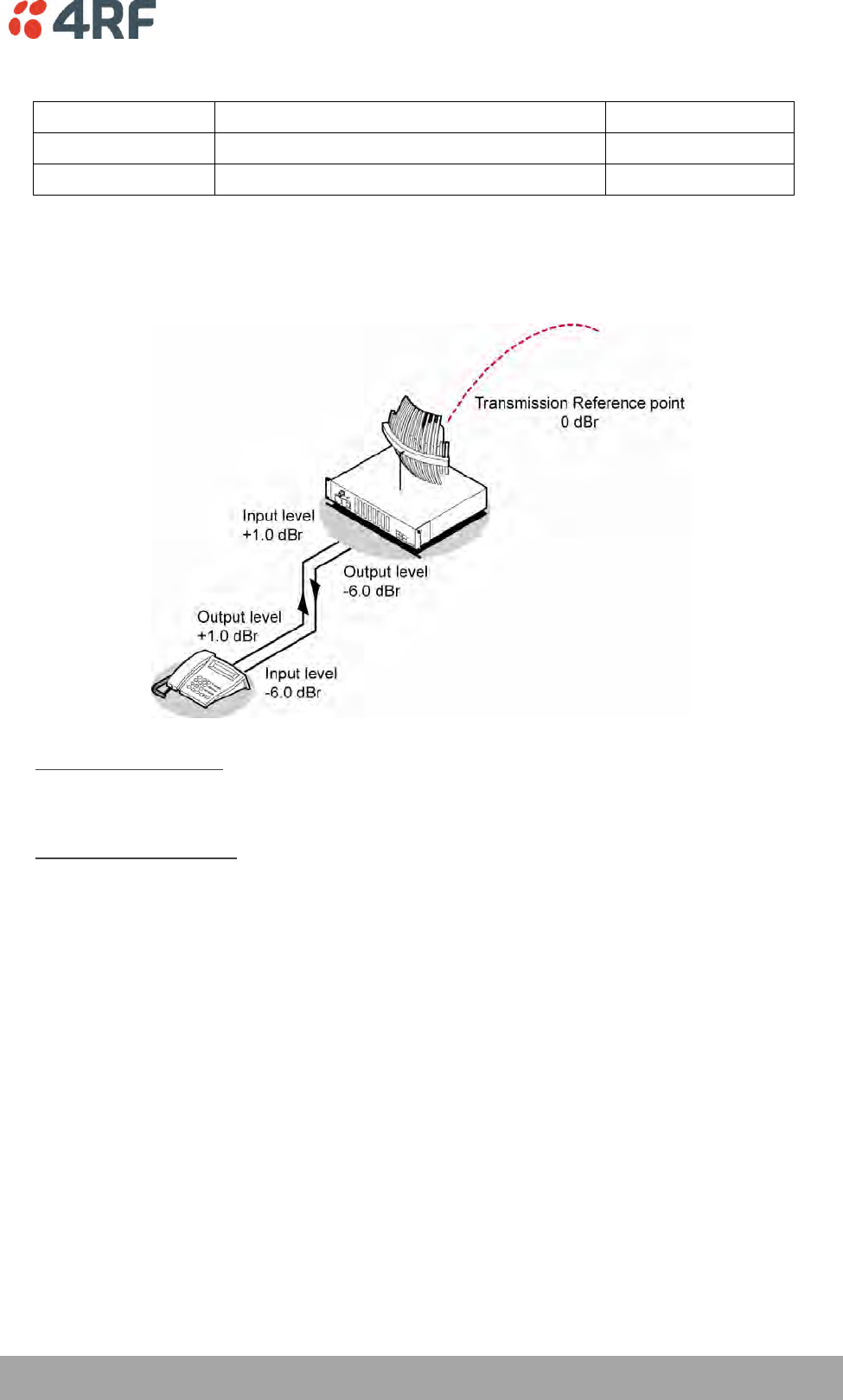
Configuring the Traffic Interfaces | 113
Aprisa XE User Manual
3. Set the DFXS Input Level and the Output Level required:
Signal Direction
Level adjustment range
Default setting
Input Level (Li)
-9.0 dBr to +3.0 dBr in 0.5 dB steps
+1.0 dBr
Output Level (Lo)
-9.5 dBr to +2.5 dBr in 0.5 dB steps
-6.0 dBr
In the example shown below, the Customer Premises Equipment is a telephone connected to a DFXS
card.
The levels are set based on the system using a 0 dBr transmission reference point.
DFXS Input Level setting
The telephone has a nominal output level of +1 dBr. To achieve a transmission reference point
transmit level of 0 dBr, the DFXS Input Level is set to +1 dBr (effective T pad loss of 1 dB).
DFXS Output Level setting
The telephone has a nominal input level of -6 dBr. With a transmission reference point received level
of 0 dBr, the DFXS Output level is set to -6 dBr (effective R pad loss of 6 dB).
4. Click Apply to apply changes or Reset to restore the previous configuration.
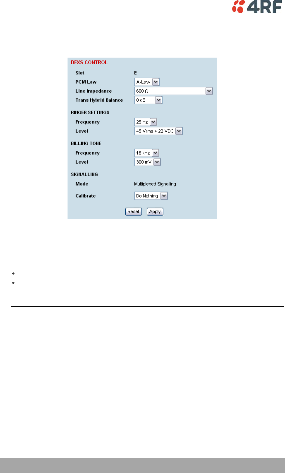
114 | Configuring the Traffic Interfaces
Aprisa XE User Manual
5. Select the DFXS Control.
The DFXS Control page sets values for both ports on the DFXS card. The cards are shipped with the
default values shown in the illustration below:
'Slot' shows the slot the DFXS interface card is plugged into in the terminal (A – H).
6. Select the DFXS PCM Law.
This option sets the companding law used by both ports on the DFXS card.
A-Law is used internationally (default)
µ-Law is used in North America and Japan.
Note: To run a mixture of µ-Law and A-Law interfaces, multiple DFXS cards are necessary.
Configuring the Traffic Interfaces | 115
Aprisa XE User Manual
7. Select the DFXS Line Impedance
This option sets the DFXS line termination impedance and the hybrid balance impedance to the same
value.
Selection
Description
600 Ω
Standard equipment impedance
Default
600 Ω + 2.16 uF
Standard equipment impedance with low frequency
roll-off
900 Ω
Typically used on loaded cable pairs
900 Ω + 2.16 uF
Typically used on loaded cable pairs with low
frequency roll-off
TN12
Standard complex impedance for Australia
TBR21
Widely deployed complex impedance
BT3
Standard complex impedance for New Zealand
On a short line (< 100 meters), the selected impedance should match the impedance of the phone
(off-hook).
On a long line (> 1000 meters), the selected impedance should match the impedance of the phone
(off-hook) as seen through the line.
If you are not sure what the expected impedance value should be, check with the CPE equipment
supplier.
8. Set the DFXS Transhybrid Balance (usually not required to change).
The default Transhybrid Balance value (0 dB), provides the best circuit performance where the
balance impedance (set by the Line Impedance setting) matches the impedance of the line.
You should only adjust the transhybrid balance when the balance impedance does not match the
actual line impedance. You can achieve small circuit improvements using this option.
9. Set the DFXS Ringer Frequency.
This option sets the DFXS Ringing Frequency.
Selection
Description
17 Hz
Used in older networks
25 Hz
Standard ringing frequency
Default
50 Hz
Used by some telephone exchanges
116 | Configuring the Traffic Interfaces
Aprisa XE User Manual
10. Set the DFXS Ringer Output Voltage.
This option sets the DFXS open circuit Ringing Output Voltage which is sourced via an internal ringing
resistance of 178 per port.
The DC offset on the AC ringing signal enables ring trip to occur with a DC loop either during ringing
cycles. The normal DC line feed voltage enables ring trip to occur with a DC loop in the silent period
between the ringing cycles.
Selection
Description
60 Vrms + 0 VDC
Outputs 60 VRMS ringing with no DC offset
Maximum ringing voltage for high ringing load
applications but no DC ring trip
55 Vrms + 10 VDC
Outputs 55 VRMS ringing with a 10 VDC offset
Medium ringing load applications
50 Vrms + 18 VDC
Outputs 50 VRMS ringing with a 18 VDC offset
Above average ringing load applications
45 Vrms + 22 VDC
Outputs 45 VRMS ringing with a 22 VDC offset
Typical application
Default
40 Vrms + 24 VDC
Outputs 40 VRMS ringing with a 24 VDC offset
Lowest terminal power consumption
11. Select the DFXS Billing Tone Frequency.
This option sets the frequency of billing tone generation. If you are not sure what the expected
frequency of the billing tone should be, check with the exchange equipment supplier.
Selection
Description
12 kHz
Use if the CPE requires a 12 kHz billing tone signal
16 kHz
Use if the CPE requires a 16 kHz billing tone signal
Default
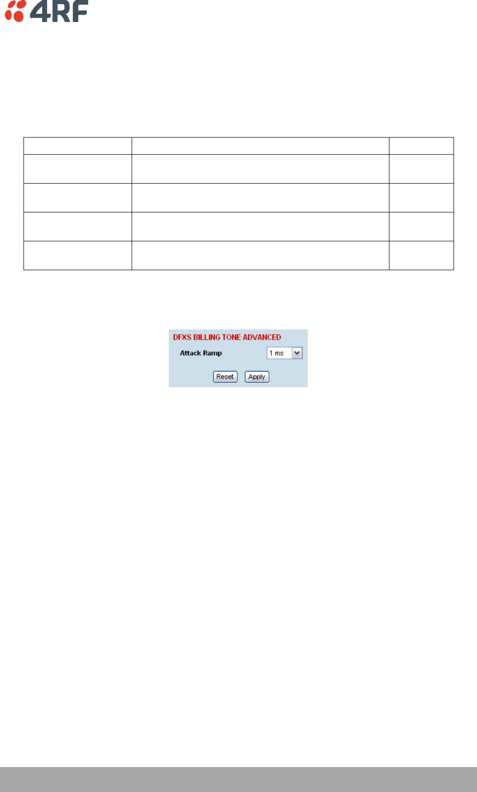
Configuring the Traffic Interfaces | 117
Aprisa XE User Manual
12. Select the DFXS Billing Tone Level.
This option sets the DFXS billing tone output level which is defined as the voltage into 200 Ω with a
source impedance equal to the Line Impedance setting.
The billing tone voltage into 200 Ω is limited by the maximum open circuit voltage of 1 Vrms. The drop
down list reflects the maximum allowable billing tone output voltage for the Line Impedance setting
selected.
Selection
Description
400 mV rms
Billing tone voltage setting available for line
impedances of TN12, BT3 and TBR21.
300 mV rms
Billing tone voltage setting available for line
impedances of TN12, BT3, TBR21 and 600 Ω.
Default
200 mV rms
Billing tone voltage setting available for line
impedances of TN12, BT3, TBR21, 600 Ω and 900 Ω.
100 mV rms
Billing tone voltage setting available for all line
impedance settings.
13. The DFXS billing tone Attack Ramp time can be adjusted to reduce the interference which can be
produced when a signal turns on quickly. The attack ramp time is how long the billing tone generator
takes to ramp up to full level when it is turned. The default ramp time is 1 ms.

118 | Configuring the Traffic Interfaces
Aprisa XE User Manual
14. The DFXS Signalling Advanced options are used to control the four CAS bits ABCD in the DFXO to DFXS
direction of transmission and one CAS bit A in the DFXS to DFXO direction of transmission. This option
sets the signalling for both DFXS card ports.
Transparent Normal mode is used for normal traffic and Transparent Inverted mode can be used for
special signalling requirements when a function needs to be reversed e.g. to change the idle polarity
of the DFXS line feed voltage.
Forced modes are used to disable particular functions e.g. when polarity reversals are not required.
They can also be used for system testing e.g. to apply DFXS continuous ringing output
Selection
Description
Transparent Normal
Normal transparent transmission of the CAS bit
Default
Transparent
Inverted
Transparent transmission of the CAS bit but inverts the
polarity.
Forced Normal
Sets the CAS bit to 1 (inactive).
Forced Inverted
Sets the CAS bit to 0 (active).
DFXO to DFXS
CAS Bit
Forced Normal
Forced Inverted
A bit (fault)
Sets the CAS A bit to 1
continuous fault state
Sets the CAS A bit to 0
no fault state
B bit (ring)
Sets the CAS B bit to 1
no DFXS ringing output.
Sets the CAS B bit to 0
continuous DFXS ringing output.
C bit (billing)
Sets the CAS C bit to 1
no DFXS billing tone output.
Sets the CAS C bit to 0
continuous DFXS billing tone
output.
D bit (reversal)
Sets the CAS D bit to 1
no DFXS polarity reversal
Sets the CAS D bit to 0
continuous DFXS polarity reversal
From DFXS to DFXO
CAS Bit
Forced Normal
Forced Inverted
A bit (off hook)
Sets the CAS A bit to 1
no DFXO off hook
Sets the CAS A bit to 0
continuous DFXO off hook

Configuring the Traffic Interfaces | 119
Aprisa XE User Manual
QJET to DFXS
CAS Bit
Forced Normal
Forced Inverted
A bit (ring)
Sets the CAS A bit to 1
no DFXS ringing output.
Sets the CAS A bit to 0
continuous DFXS ringing output.
B bit (na)
Not Applicable
Not Applicable
C bit (na)
Not Applicable
Not Applicable
D bit (na)
Not Applicable
Not Applicable
From DFXS to QJET
CAS Bit
Forced Normal
Forced Inverted
A bit (off hook)
Sets the CAS A bit to 1
Idle state to E1 port
Sets the CAS A bit to 0
Off hook state to E1 port
15. Click Apply to apply changes or Reset to restore the previous configuration.
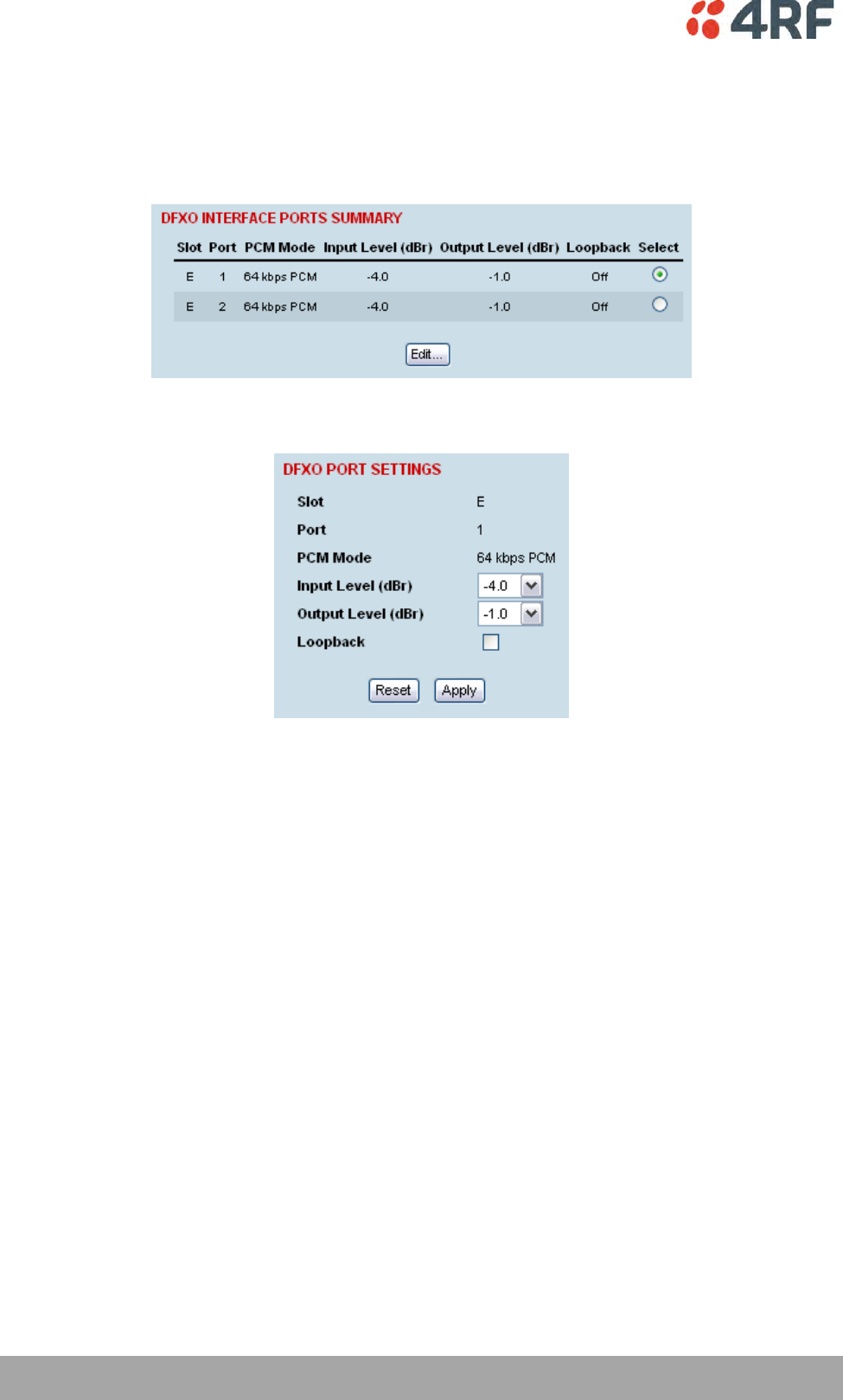
120 | Configuring the Traffic Interfaces
Aprisa XE User Manual
DFXO Port Settings
1. Select Link or Local or Remote > Interface > Interface Summary, then select the DFXO interface and
click Configure Interface.
2. Select the DFXO port to configure, and click Edit.
'Slot' shows the slot the DFXO interface card is plugged into in the terminal (A – H).
'Port' shows the interface port number (1-2).
‘PCM Mode’ shows the current mode assigned to the port by the cross connect.
‘Loopback’ loops back the port digital paths to return the port analogue signal back to the customer.

Configuring the Traffic Interfaces | 121
Aprisa XE User Manual
3. Set the DFXO Input Level and the Output Level required:
Signal Direction
Level adjustment range
Default setting
Input Level (Li)
-10.0 dBr to +1.0 dBr in 0.5 dB steps
-4.0 dBr
Output Level (Lo)
-10.0 dBr to +1.0 dBr in 0.5 dB steps
-1.0 dBr
In the example shown below, the PSTN exchange line card is connected to a DFXO card.
The levels are set based on the system using a 0 dBr transmission reference point.
DFXO Input Level setting
The exchange line card has a nominal output level of -6 dBr. To achieve a digital reference point
transmit level of -2.0 dBm0, the DFXO input level is set to -4.0 dBr (effective T pad gain of 4.0 dB).
The deliberate 2 dB of loss between the exchange line card and the DFXO provides a 2 dB of overall
circuit loss between the DFXO and the DFXS.
DFXO Output Level setting
The exchange line card has a nominal input level of +1.0 dBr. With a transmission reference point
received level of -2.0 dBm0, the DFXO output level is set to -1.0 dBr (effective R pad loss of 1.0 dB).
The deliberate 2 dB of loss between the exchange line card and the DFXO provides a 2 dB of overall
circuit loss between the DFXS and the DFXO.
4. Click Apply to apply changes or Reset to restore the previous configuration.
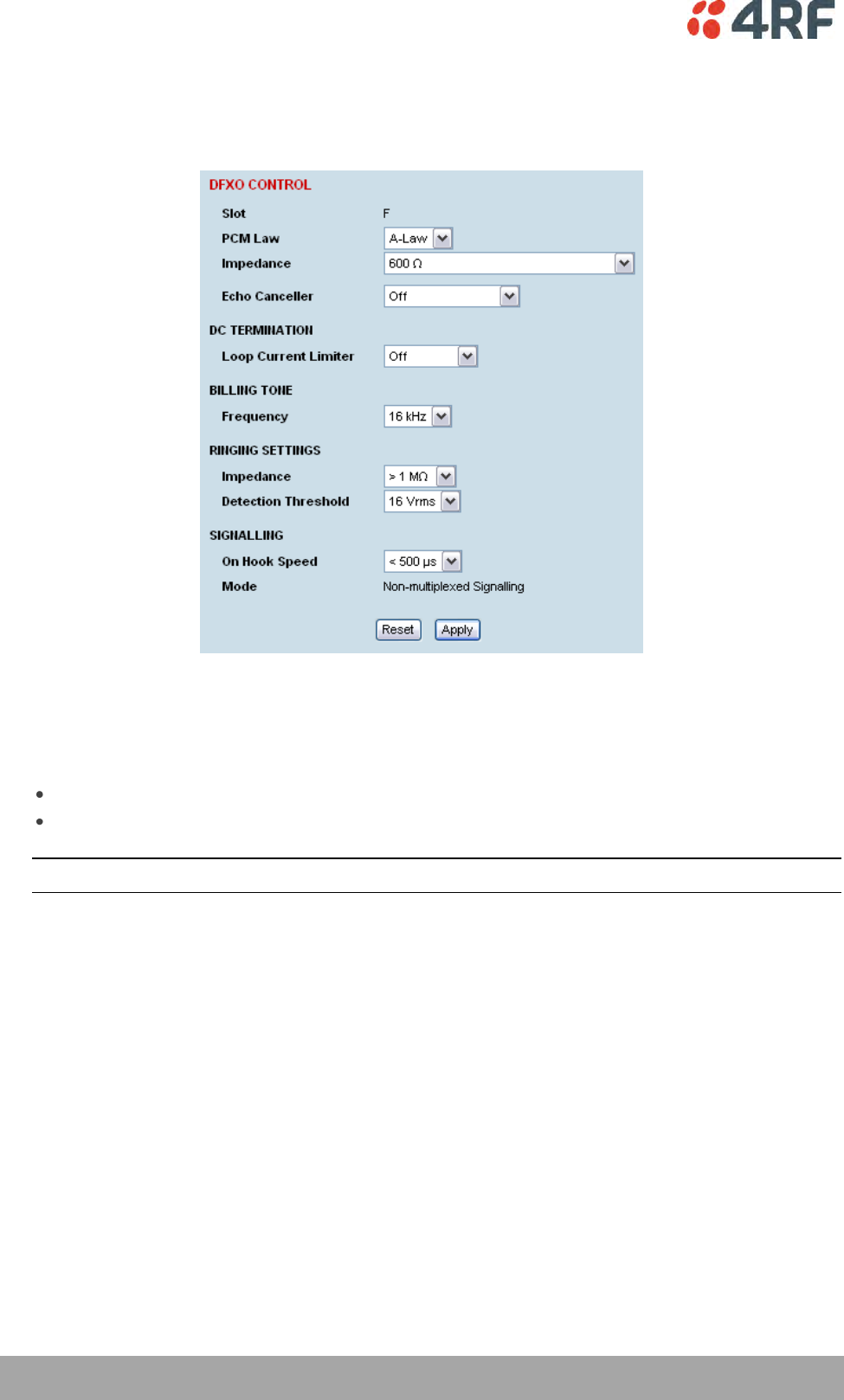
122 | Configuring the Traffic Interfaces
Aprisa XE User Manual
5. Select the DFXO Control.
The DFXO Control page sets values for both ports on the DFXO card. The cards are shipped with the
default values shown in the illustration below:
'Slot' shows the slot the DFXO interface card is plugged into in the terminal (A – H).
6. Select the DFXO PCM Law.
This option sets the companding law used by both ports on the DFXO card.
A-Law is used internationally (default)
µ-Law is used in North America and Japan.
Note: To run a mixture of µ-Law and A-Law interfaces, multiple DFXO cards are necessary.

Configuring the Traffic Interfaces | 123
Aprisa XE User Manual
7. Select the DFXO Impedance
This option sets the DFXO line termination impedance and the hybrid balance impedance to the same
value.
Selection
Description
600 Ω
Standard equipment impedance
Default
600 Ω + 2.16 uF
Standard equipment impedance with low frequency roll-off
900 Ω
Typically used on loaded cable pairs
900 Ω + 2.16 uF
Typically used on loaded cable pairs with low frequency roll-off
TN12
Standard complex impedance for Australia
TBR21
Widely deployed complex impedance
BT3
Standard complex impedance for New Zealand
BT Network
Standard complex impedance for UK
China
Standard complex impedance for China
On a short line (< 100 metres), the selected impedance should match the impedance of the
exchange line card.
On a long line (> 1000 metres), the selected impedance should match the impedance of the
exchange line card as seen through the line.
If you are not sure what the expected impedance value should be, check with the exchange
equipment supplier.
8. Enable the DFXO Echo Canceller if required.
The DFXO Echo Canceller provides up to 64 ms of echo cancellation. This feature is only available on
Rev D (and later) DFXO cards.
Analogue data devices e.g. modems send a disable signal to disable any echo canceller in circuit while
it trains its own echo canceller. There are two possible disable signals. ITU G.164 specifies a disable
signal of a single 2100 Hz tone and ITU G.165 specifies a disable signal of 2100 Hz tone with phase
reversals every 450 ms.
Selection
Description
Off
No echo canceller operation.
Default
On
Echo canceller operational but without disabling.
Auto Disable
G.164
Echo canceller operational with automatic disabling using ITU
G.164 2100 Hz tone.
Auto Disable
G.165
Echo canceller operational with automatic disabling using ITU
G.165 2100 Hz tone with phase reversals every 450 ms.
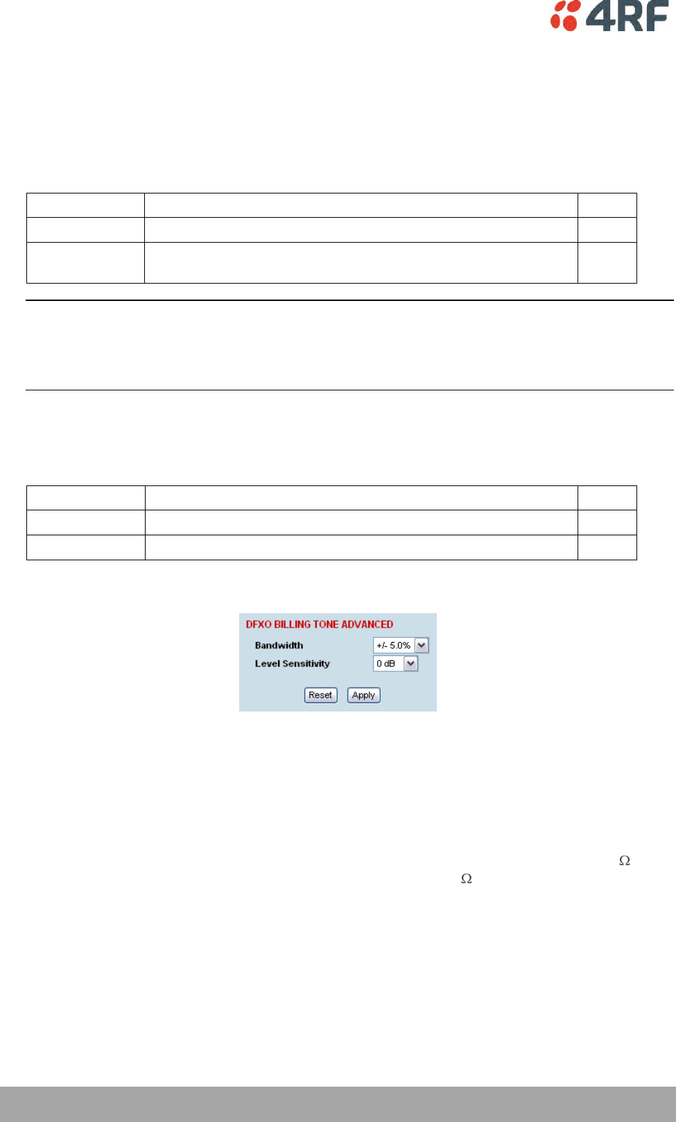
124 | Configuring the Traffic Interfaces
Aprisa XE User Manual
9. Set the DFXO Loop Current Limiter.
This option turns on a current limiter which limits the maximum current that can be drawn from the
exchange line card by the DFXO interface.
As a general rule, only one interface should current limit so if the exchange interface current limits,
the DFXO interface should be set to current limit off.
Selection
Description
Off
Use if the exchange line interface uses current limiting.
Default
On (60 mA)
Use if the exchange line interface does not use current limiting.
The DFXO limits the line loop current to 60 mA.
Note: The DFXO provides an early warning over current alarm ‘fxoCurrentOvld’ if the loop current
exceeds 100 mA for 2 seconds. This alarm clears when the loop current is less than 90 mA.
The DFXO also provides an over current safety shut down limit which removes its line loop if the loop
current exceeds 160 mA.
10. Select the DFXO Billing Tone Frequency.
This option sets the frequency of billing tone detection. If you are not sure what the expected
frequency of the billing tone should be, check with the exchange equipment supplier.
Selection
Description
12 kHz
Use if the exchange outputs 12 kHz billing tone
16 kHz
Use if the exchange outputs 16 kHz billing tone
Default
11. The DFXO Billing Tone Advanced sets the billing tone Bandwidth and the billing tone Level Sensitivity.
The DFXO billing tone Bandwidth determines the bandwidth of the band pass filter that is used by the
billing tone detector in terms of +/- % of the billing tone frequency.
The adjustment range is +/- 1.5% to +/- 7.5% and the default value is +/- 5.0%.
The DFXO billing tone Level Sensitivity determines the DFXO detection sensitivity.
The adjustment range is 0 dB (metering detection threshold of -17 dBm measured across 200 ) to 27
dB (metering detection threshold of -40 dBm measured across 200 ) in 1 dB steps and the default
value is 0 dB.
Configuring the Traffic Interfaces | 125
Aprisa XE User Manual
12. Select the DFXO On Hook Speed.
This option sets the slope of the transition between off-hook and on-hook.
Selection
Description
< 500 μs
Off-hook to on-hook slope of < 500 μs
Default
3 ms
Off-hook to on-hook slope of 3 ms ± 10% that meets ETSI standard
25 ms
Off-hook to on-hook slope of 25 ms± 10% used to reduce transient
interference in copper cable
13. Select the DFXO ringer Impedance.
This option sets the DFXO ringing input impedance as seen by a sine wave ringing signal applied to the
DFXO 2 wire port at the frequency of ringing.
Selection
Description
> 1 M
DFXO input impedance to ringing of > 1 M
Default
> 12 kΩ
DFXO input impedance to ringing of > 12 kΩ
14. Select the DFXO ringer Detection Threshold.
This option sets the DFXO ringing detect threshold.
Selection
Description
16 Vrms
DFXO detects ringing voltages of 16 Vrms or greater (does not
detect ringing below 13 Vrms)
Default
26 Vrms
DFXO detects ringing voltages of 26 Vrms or greater (does not
detect ringing below 19 Vrms)
49 Vrms
DFXO detects ringing voltages of 49 Vrms or greater (does not
detect ringing below 40 Vrms)
It is recommended that the ringer Detection Threshold be set to 49 Vrms if a DFXO ringer impedance
of > 12 kΩ is selected.
Note: The Signalling Mode is set in the Cross Connections application (see page 171).
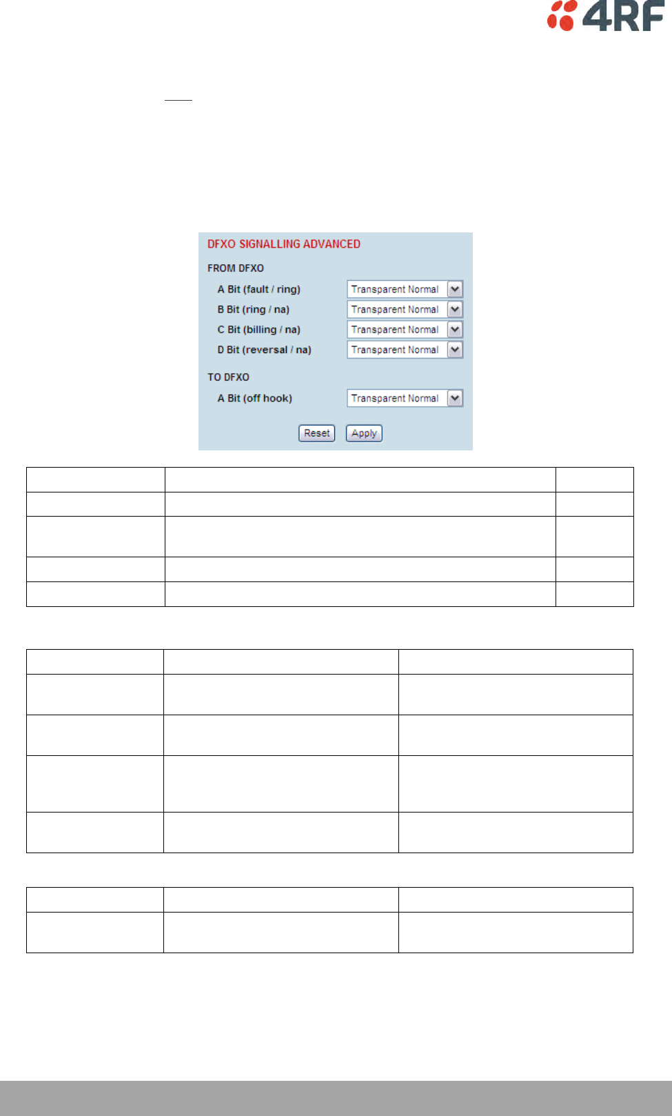
126 | Configuring the Traffic Interfaces
Aprisa XE User Manual
15. The DFXO Signalling Advanced options are used to control the four CAS bits ABCD in the DFXO to DFXS
direction of transmission and one CAS bit A in the DFXS to DFXO direction of transmission. This option
sets the signalling for both DFXO card ports.
Transparent Normal mode is used for normal traffic and Transparent Inverted mode can be used for
special signalling requirements when a function needs to be reversed e.g. to change the idle polarity
of the DFXS line feed voltage.
Forced modes are used to disable particular functions e.g. when polarity reversals are not required.
They can also be used for system testing e.g. to apply DFXO continuous off hook
Selection
Description
Transparent Normal
Normal transparent transmission of the CAS bit
Default
Transparent
Inverted
Transparent transmission of the CAS bit but inverts the
polarity.
Forced Normal
Sets the CAS bit to 1.
Forced Inverted
Sets the CAS bit to 0.
From DFXO to DFXS
CAS Bit
Forced Normal
Forced Inverted
A bit (fault)
Sets the CAS A bit to 1
continuous fault state
Sets the CAS A bit to 0
no fault state
B bit (ring)
Sets the CAS B bit to 1
no DFXS ringing output.
Sets the CAS B bit to 0
continuous DFXS ringing output.
C bit (billing)
Sets the CAS C bit to 1
no DFXS billing tone output.
Sets the CAS C bit to 0
continuous DFXS billing tone
output.
D bit (reversal)
Sets the CAS D bit to 1
no DFXS polarity reversal
Sets the CAS D bit to 0
continuous DFXS polarity reversal
DFXS to DFXO
CAS Bit
Forced Normal
Forced Inverted
A bit (off hook)
Sets the CAS A bit to 1
no DFXO off hook
Sets the CAS A bit to 0
continuous DFXO off hook

Configuring the Traffic Interfaces | 127
Aprisa XE User Manual
QJET to DFXS
CAS Bit
Forced Normal
Forced Inverted
A bit (ring)
Sets the CAS A bit to 1
no DFXS ringing output.
Sets the CAS A bit to 0
continuous DFXS ringing output.
B bit (na)
Not Applicable
Not Applicable
C bit (na)
Not Applicable
Not Applicable
D bit (na)
Not Applicable
Not Applicable
From DFXS to QJET
CAS Bit
Forced Normal
Forced Inverted
A bit (off hook)
Sets the CAS A bit to 1
Idle state to E1 port
Sets the CAS A bit to 0
Off hook state to E1 port
16. Click Apply to apply changes or Reset to restore the previous configuration.
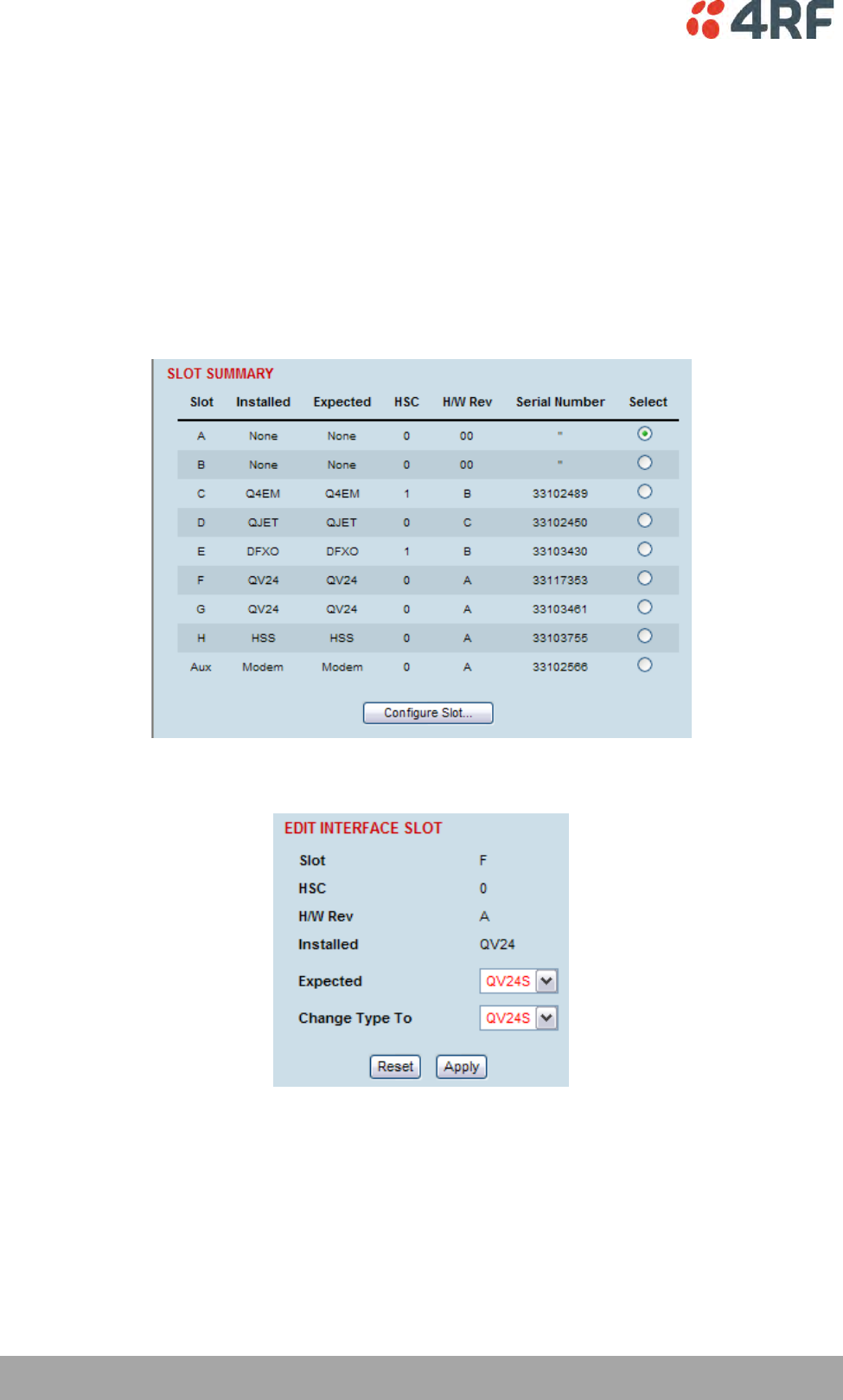
128 | Configuring the Traffic Interfaces
Aprisa XE User Manual
QV24 Serial Interface Card
There are two modes of operation of the QV24 Serial Interface Card; QV24 asynchronous and QV24S
synchronous. The mode is changed with the Slot Summary.
Changing the QV24 mode changes all four ports on the interface card.
To change the QV24 mode:
1. Select Link or Local or Remote > Interface > Slot Summary, then select the QV24 interface slot and
click Configure Slot.
2. Select the QV24 mode required with Expected.
3. Select the QV24 mode required with Change Type To and click Apply.
4. Reboot the terminal with a Hard Reboot (see ‘Rebooting the Terminal’ on page 233).
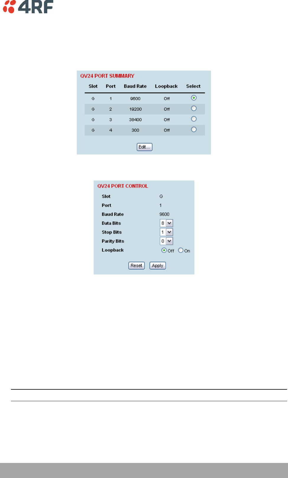
Configuring the Traffic Interfaces | 129
Aprisa XE User Manual
QV24 Port Settings
A QV24 interface is always configured as a DCE.
1. Select Link or Local or Remote > Interface > Interface Summary, then select the QV24 interface and
click Configure Interface.
2. Select the QV24 port to configure, and click Edit.
'Slot' shows the slot the QV24 interface card is plugged into in the terminal.
'Port' shows the interface port number (1-4).
‘Baud Rate’ shows the current baud rate assigned to the port by the cross connect.
‘Loopback’ loops back the port data to the customer (default is no loopback).
3. Set the number of Data Bits (default is 8 bits).
4. Set the number of Stop Bits (default is 1 bit).
5. Set the number of Parity Bits (default is 0 bits).
6. Click Apply to apply changes or Reset to restore the previous configuration.
Tip: The Quick Links box provides links to other related pages.
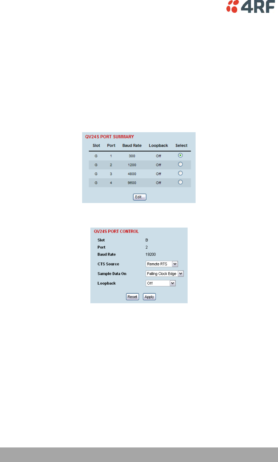
130 | Configuring the Traffic Interfaces
Aprisa XE User Manual
QV24S Port Settings
There are two modes of operation of the QV24S synchronous, synchronous and over sampling modes.
A QV24S interface is always configured as a DCE.
Synchronous Mode
In synchronous mode, interface data is synchronously mapped to radio capacity using proprietary subrate
multiplexing. QV24S interfaces are required at both ends of the circuit.
1. Select Link or Local or Remote > Interface > Interface Summary, then select the QV24S interface and
click Configure Interface.
2. Select the QV24S port to configure, and click Edit.
'Slot' shows the slot the QV24S interface card is plugged into in the terminal.
'Port' shows the interface port number (1-4).
‘Baud Rate’ shows the current baud rate assigned to the port by the cross connect.
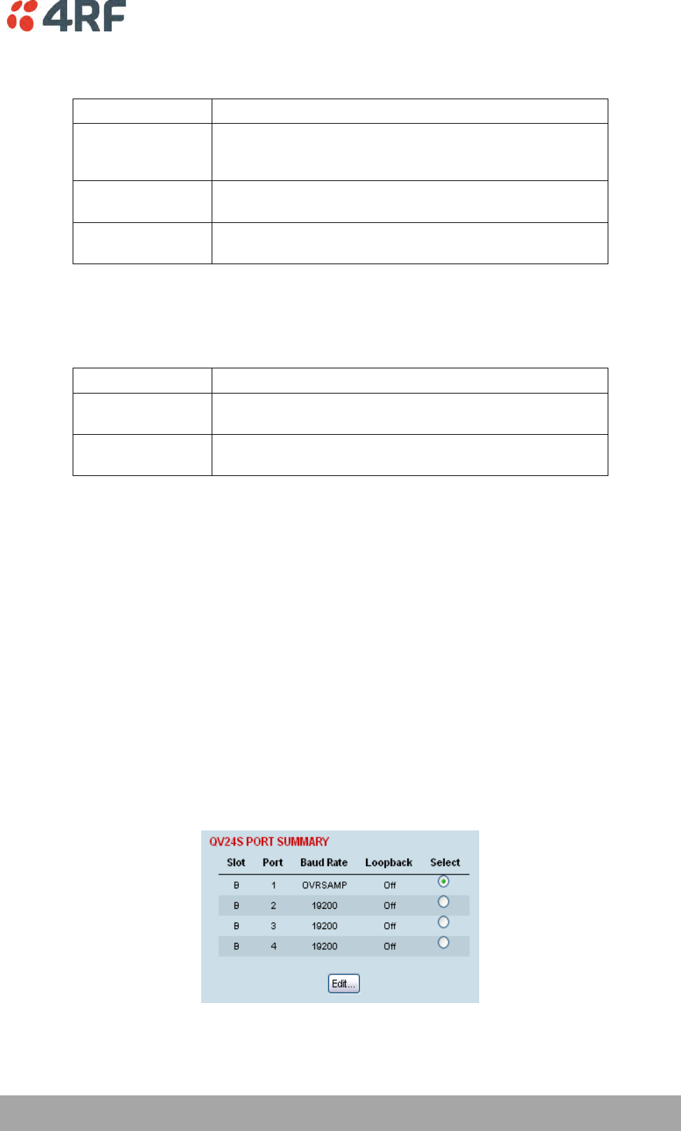
Configuring the Traffic Interfaces | 131
Aprisa XE User Manual
3. The CTS Source defines the mode in which the CTS signal responds to the remote DTE. Three options
are available:
CTS Source
Function
Remote RTS
The local CTS follows the remote RTS signal.
In the case of radio link failure (when cross connected over
the link) the signal goes to OFF.
Local RTS
The local CTS signal follows the local RTS.
The status of the link does not impact on the CTS signal.
On Permanent
The local CTS is in a permanent ON (+ve) state.
This does not go to OFF if the link fails.
Note that the CTS behaviour is not impacted by the operation of the card loopbacks.
4. The Sample Data On defines the received clock edge on which the received data is clocked into the
port. Two options are available:
Sample Data On
Function
Falling Clock Edge
The falling edge of the XTXC is used to clock data into the
port.
Rising Clock Edge
The rising edge of the XTXC is used to clock data into the
port.
5. ‘Loopback’ loops back the port data to the customer (default is no loopback).
6. Click Apply to apply changes or Reset to restore the previous configuration.
Over Sampling Mode
In over sampling mode, 64 kbit/s of radio capacity is allocated to the circuit and the incoming interface
data is sampled at a fixed 64 kHz. This timeslot can be cross connected to an E1 or T1. This over sampling
mode can be operated up to 19.2 kbit/s.
There will be some unavoidable distortion in mark space ratios (jitter) of the transported V.24 circuit. This
effect will become progressively more significant as the baud rate of the V.24 circuit increases or the
number of data conversions increases.
In over sampling mode, the DTE clock input is not used and there is no DCE output clock available.
1. Select Link or Local or Remote > Interface > Interface Summary, then select the QV24S interface and
click Configure Interface.
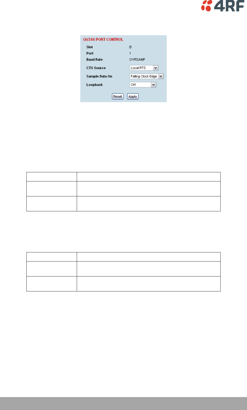
132 | Configuring the Traffic Interfaces
Aprisa XE User Manual
2. Select the QV24S port to configure, and click Edit.
'Slot' shows the slot the QV24S interface card is plugged into in the terminal.
'Port' shows the interface port number (1-4).
A Baud Rate of ‘OVRSAMP’ indicates that the QV24S has been configured for synchronous over
sampling mode in the Cross Connections application.
3. The CTS Source defines the mode in which the CTS signal responds to the remote DTE. Two options
are available:
CTS Source
Function
Local RTS
The local CTS signal follows the local RTS.
The status of the link does not impact on the CTS signal.
On Permanent
The local CTS is in a permanent ON (+ve) state.
This does not go to OFF if the link fails.
Note that the CTS behaviour is not impacted by the operation of the card loopbacks.
4. The Sample Data On defines the received clock edge on which the received data is clocked into the
port. Two options are available:
Sample Data On
Function
Falling Clock Edge
The falling edge of the XTXC is used to clock data into the
port.
Rising Clock Edge
The rising edge of the XTXC is used to clock data into the
port.
5. ‘Loopback’ loops back the port data to the customer (default is no loopback).
6. Click Apply to apply changes or Reset to restore the previous configuration.
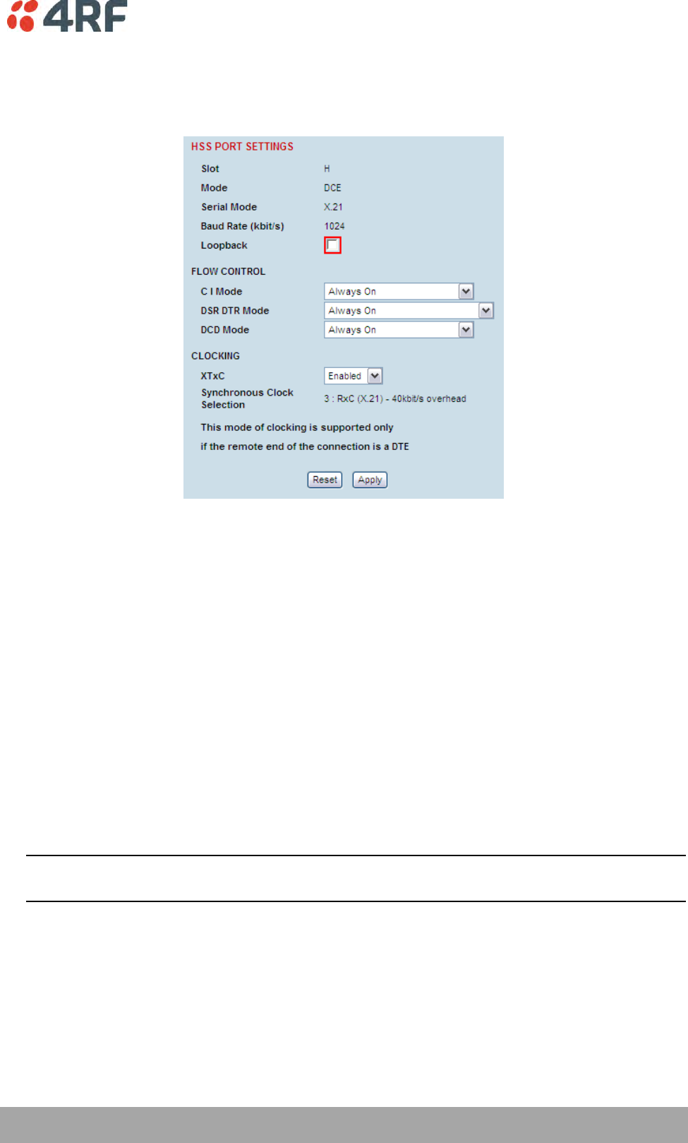
Configuring the Traffic Interfaces | 133
Aprisa XE User Manual
HSS Port Settings
1. Select Link or Local or Remote > Interface > Interface Summary, then select HSS (High-speed
Synchronous Serial) interface and click Configure Interface.
'Slot' shows the slot the HSS interface card is plugged into in the terminal (A – H).
'Mode' shows the interface mode provided by the HSS interface (either DTE or DCE). If there is no
interface cable plugged into the HSS port, the ‘Mode’ will show ‘No Cable’.
'Serial Mode' shows interface type provided by the HSS interface (X.21, V.35 etc). If there is no
interface cable plugged into the HSS port, the ‘Serial Mode’ will show ‘None’.
‘Baud Rate (kbit/s)’ shows the current baud rate assigned to the port by the cross connect.
‘Loopback’ loops back the port data to the customer (default is no loopback).
‘Synchronous Clock Selection’ shows the current clocking mode assigned to the port by the cross
connect.
2. Set the HSS RTS CTS Mode as required.
The RTS CTS mode controls the state of the outgoing interface RTS CTS control line.
When the HSS interface is DCE, the outgoing control line is CTS. When the HSS interface is DTE, the
outgoing control line is RTS.
Note: Refer to ‘HSS Handshaking and Clocking’ on page 135 for additional information on setting the
recommended handshaking mode for each application.
3. Set the HSS DSR DTR Mode as required.
The DSR DTR mode controls the state of the outgoing interface DSR DTR control line.
When the HSS interface is DCE, the outgoing control line is DSR. When the HSS interface is DTE, the
outgoing control line is DTR.

134 | Configuring the Traffic Interfaces
Aprisa XE User Manual
4. Set the HSS DCD Mode as required.
The DCD mode controls the state of the outgoing interface DCD control line.
This setting is only relevant if the HSS interface is DCE.
5. Enable or disable the HSS XTxC control, as required.
Depending on the clocking mode (see ‘HSS Handshaking and Clocking’ on page 135) selected, altering
this setting will allow the terminal clock to be substituted for the external XTxC signal.
6. Click Apply to apply changes or Reset to restore the previous configuration.
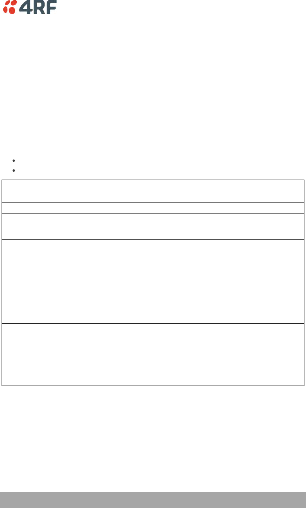
Configuring the Traffic Interfaces | 135
Aprisa XE User Manual
HSS Handshaking and Clocking Modes
This section provides detailed information on selecting the recommended HSS handshaking and clocking
modes for the HSS interface card (see ‘HSS port settings’ on page 133).
HSS Handshaking and Control Line Function
HSS X.21 Compatibility
In general X.21 usage, the C and I wires function as handshaking lines analogous to RTS/CTS handshakes.
For switched carrier applications, the I wire is used to emulate carrier indications (DCD) function.
HSS RTS / CTS Mode
Set the RTS CTS Mode as required according to the table below. This field controls the state of the
outgoing interface control line.
When the HSS interface is DCE, the outgoing control line is CTS.
When the HSS interface is DTE, the outgoing control line is RTS.
RTS CTS Mode
HSS as a DCE
HSS as a DTE
Comment
Always Off
CTS driven to off state
RTS driven to off state
Always On
CTS driven to on state
RTS driven to on state
Follows
Carrier
CTS follows the state of
the RF link
RTS follows the state
of the RF link
To follow carrier is to indicate
the state of synchronization of
the RF link
Follows
Carrier +
Remote
RTS/CTS
CTS follows the state of
the RF link and the
remote terminal RTS
input control line if the
remote is a DCE. If the
remote HSS is a DTE,
then CTS follows the
state of the RF link and
the remote HSS CTS
input.
RTS follows the state
of the RF link and the
remote terminal RTS
input control line. The
remote HSS can only be
a DCE.
Control line pass-through mode
where RTS and CTS are carried
over the link from end to end.
The carrier (as above) plus the
remote terminal input control
line must be present to output
the local control line signal.
The HSS Control bit in the Cross
Connections application must
be set for the remote signalling
to operate.
Follows
Carrier +
Remote DCD
CTS follows the state of
the RF link if the remote
HSS is a DCE. If the
remote HSS is a DTE,
then CTS follows the
state of the RF link and
the remote HSS DCD
input control line.
This setting is only applicable
when the local HSS card in the
local terminal is a DCE. The HSS
Control bit in the Cross
Connections application must
be set for the remote signalling
to operate.
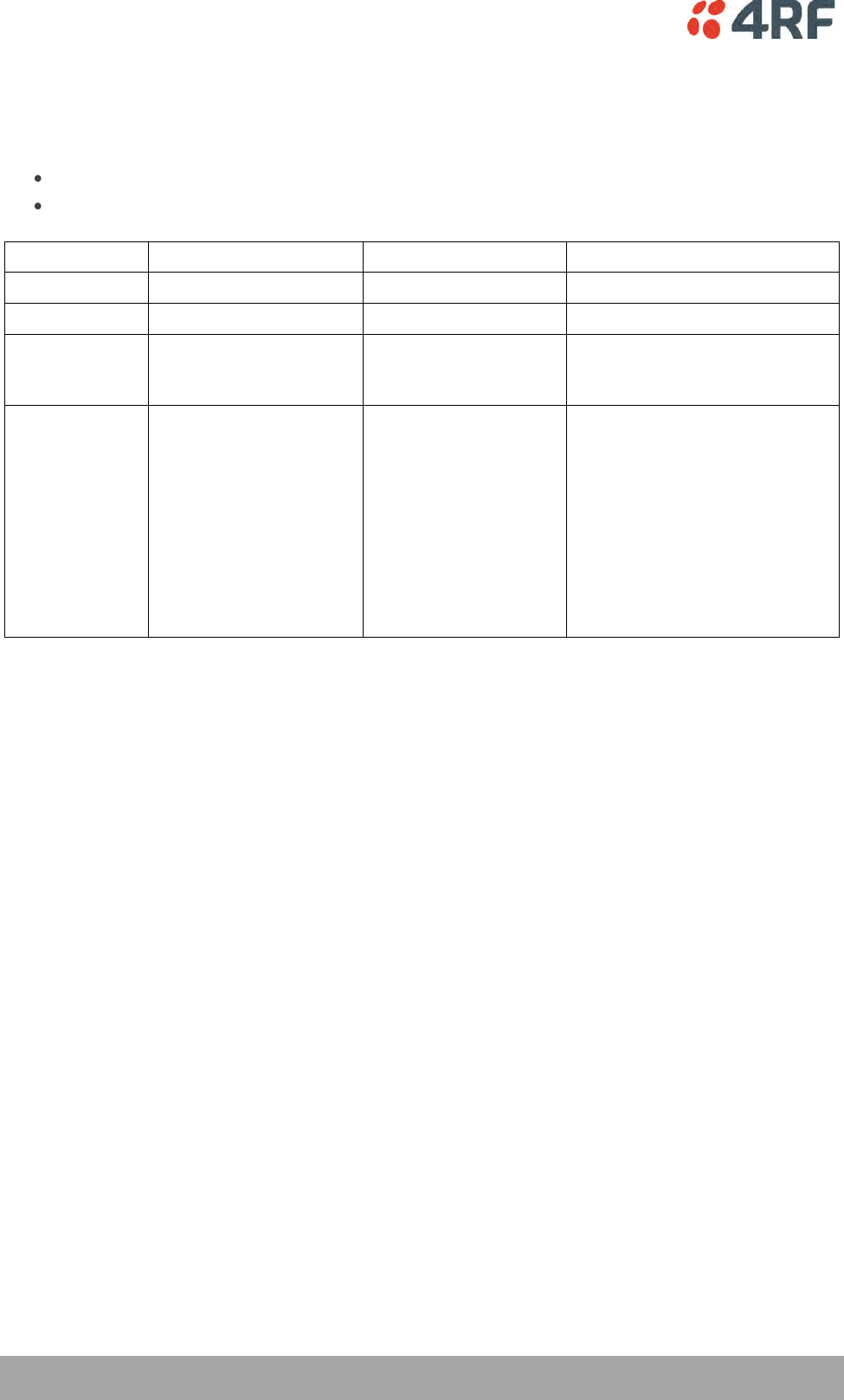
136 | Configuring the Traffic Interfaces
Aprisa XE User Manual
HSS DSR / DTR Mode
Set the DSR DTR Mode as required according to the table below. This field controls the state of the
outgoing interface control line.
When the HSS interface is DCE, the outgoing control line is DSR
When the HSS interface is DTE, the outgoing control line is DTR
DSR DTR Mode
HSS as a DCE
HSS as a DTE
Comment
Always Off
DSR driven to off state
DTR driven to off state
Always On
DSR driven to on state
DTR driven to on state
Follows Carrier
DSR follows the state of
the RF link
DTR follows the state
of the RF link
To follow carrier is to indicate
the state of synchronization of
the RF link.
Follows Carrier
+ Remote
DSR/DTR
DSR follows the state of
the RF link and the
remote terminal DSR
control line if the
remote terminal is a
DTE, or the remote DTR
if the remote terminal is
a DCE.
DTR follows the state
of the RF link and the
remote terminal DTR
control line if the
remote terminal is a
DCE. The remote HSS
can only be a DCE.
Control line pass-through mode
where DSR and DTR are carried
over the link from end to end.
The carrier (as above) plus the
remote terminal input control
line must be present to output
the local control line signal.
The HSS Control bit in the Cross
Connections application must
be set for the remote signalling
to operate.
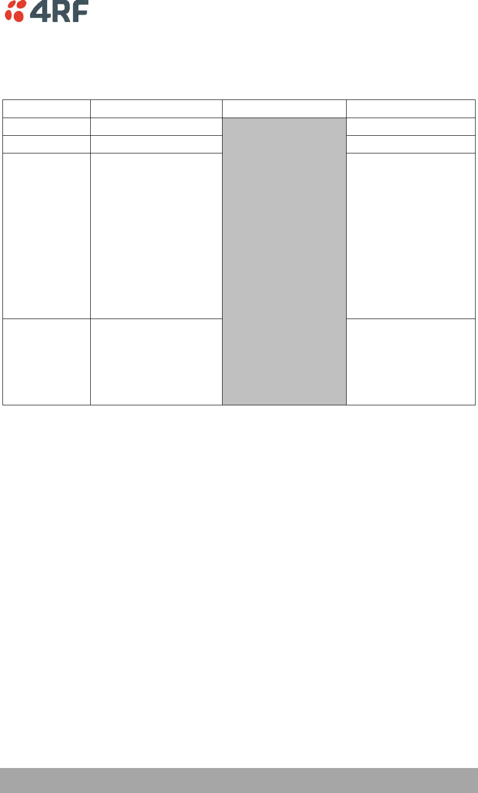
Configuring the Traffic Interfaces | 137
Aprisa XE User Manual
HSS DCD Mode
Set the DCD Mode as required according to the table below. This setting is only relevant in DCE mode.
DCD Mode
HSS as a DCE
HSS as a DTE
Comment
Always Off
DCD driven to off state
NOT applicable
Always On
DCD driven to on state
Follows Carrier +
Remote DCD
DCD follows the state of
the RF link and the remote
terminal DCD input control
line if the remote HSS is a
DTE. If the remote
terminal is a DCE, then
DCD only follows the state
of the RF link.
Control line pass-through
mode where DCD is
carried over the link from
end to end. The carrier
(as above) plus the
remote terminal input
control line must be
present to output the
local control line signal.
The HSS Control bit in the
Cross Connections
application must be set
for the remote signalling
to operate.
Follows Carrier +
Remote RTS
DCD follows the state of
the RF link and the remote
terminal RTS input control
line when the remote HSS
is a DCE.
For switched carrier
applications this provides
RTS-DCD pass through
(DCE to DCE
configuration) and DCD-
DCD pass-through (DTE to
DCE configuration).
Set the XTxC Enabled control as required. Depending on the synchronous clock selection mode selected,
disabling XTxC will allow the terminal clock to be substituted for the external XTxC signal.
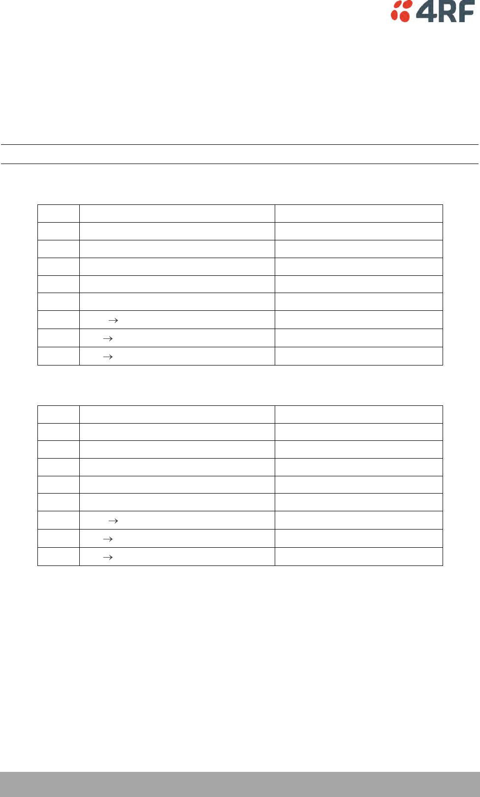
138 | Configuring the Traffic Interfaces
Aprisa XE User Manual
HSS Synchronous Clock Selection Modes
The following section describes in detail each of the recommended HSS Synchronous Clock Selection
modes for both DTE to DCE and DCE to DCE modes of operation.
The HSS clocking can be configured for clocking types of Internal clocking, pass-through clocking, and
primary / secondary master clocking. The topology of the client network determines the clock mode that
is used.
Note: Modes 3 and 4 provide only physical layer support, not X.21 protocol support.
Terminal 1 HSS as a DTE and terminal 2 HSS as a DCE - ‘Pipe Mode’
Mode
Synchronous Clock Selection mode
Clocking Type
0
Internal Clocks – No overhead
Not supported
1
RxC + XTxC – 40 kbit/s overhead
Not supported
2
RxC + TxC – 56 kbit/s overhead
Pass-through clocking
3
RxC (X.21) – 40 kbit/s overhead
Pass-through clocking (X.21 only)
4
RxC (X.21) – No overhead
Not supported
5
XTxC RxC – 40 kbit/s overhead
Not supported
6
RxC RxC – No overhead
Primary/ Secondary Master clocking
7
RxC RxC - 40 kbit/s overhead
Pass-through clocking
Terminal 1 HSS as a DCE and terminal 2 HSS as a DCE - ‘Cloud Mode’
Mode
Synchronous Clock Selection mode
Clocking Type
0
Internal Clocks – No overhead
Internal clocking
1
RxC + XTxC– 40 kbit/s overhead
Not supported
2
RxC + TxC– 56 kbit/s overhead
Not supported
3
RxC (X.21) – 40 kbit/s overhead
Not supported
4
RxC (X.21) – No overhead
Internal clocking (X.21 only)
5
XTxC RxC – 40 kbit/s overhead
Pass-through clocking
6
RxC RxC – No overhead
Not supported
7
RxC RxC - 40 kbit/s overhead
Not supported

Configuring the Traffic Interfaces | 139
Aprisa XE User Manual
HSS Clocking Types
HSS internal clocking
Internal clocking relies on the (highly accurate) terminal system clock, that is, it does not allow for any
independent clocks coming in from client equipment.
For this mode, all incoming clocks must be slaved to a clock emanating from the HSS card.
HSS pass-through clocking
The HSS card is capable in hardware of passing two clocks from one side of a link to the other. Passing a
clock means that the difference between the client clock(s) and the terminal clock is transferred across
the link continuously. Passing a single clock in each direction requires 40 kbit/s additional link overhead,
passing two clocks from DTE to DCE requires 56 kbit/s overhead, whereas relying on internal clocking
requires no overhead.
Network topology determines if passing a clock makes sense. Passing a clock is used where a client's
incoming clock must be kept independent of the clock sourced by the HSS card. The only time it makes
sense to pass two clocks is when a client DCE in one of the HSS modes provides two independent clocks,
that is, the HSS is set to Clock Mode 2.
Pass-through clocking does not require using the HSS incoming clock as a Primary or Secondary master
clock for the link, but does not preclude it either.
HSS primary / secondary master clocking
When implementing an external clock master, all other interfaces in the terminal and internal system
timings are slaved to this external clock. The remote terminal is also slaved to this master clock. This
master clock must be within 100 ppm of the accuracy of the terminal system clock, otherwise the terminal
will revert to using its internal clock. Ideally, the external clock should be much better than 100 ppm.
Mode 6 is offered for those network topologies that require RxC and TxC to be locked. For example, this is
useful when interworking with an Aprisa SE HSS interface.
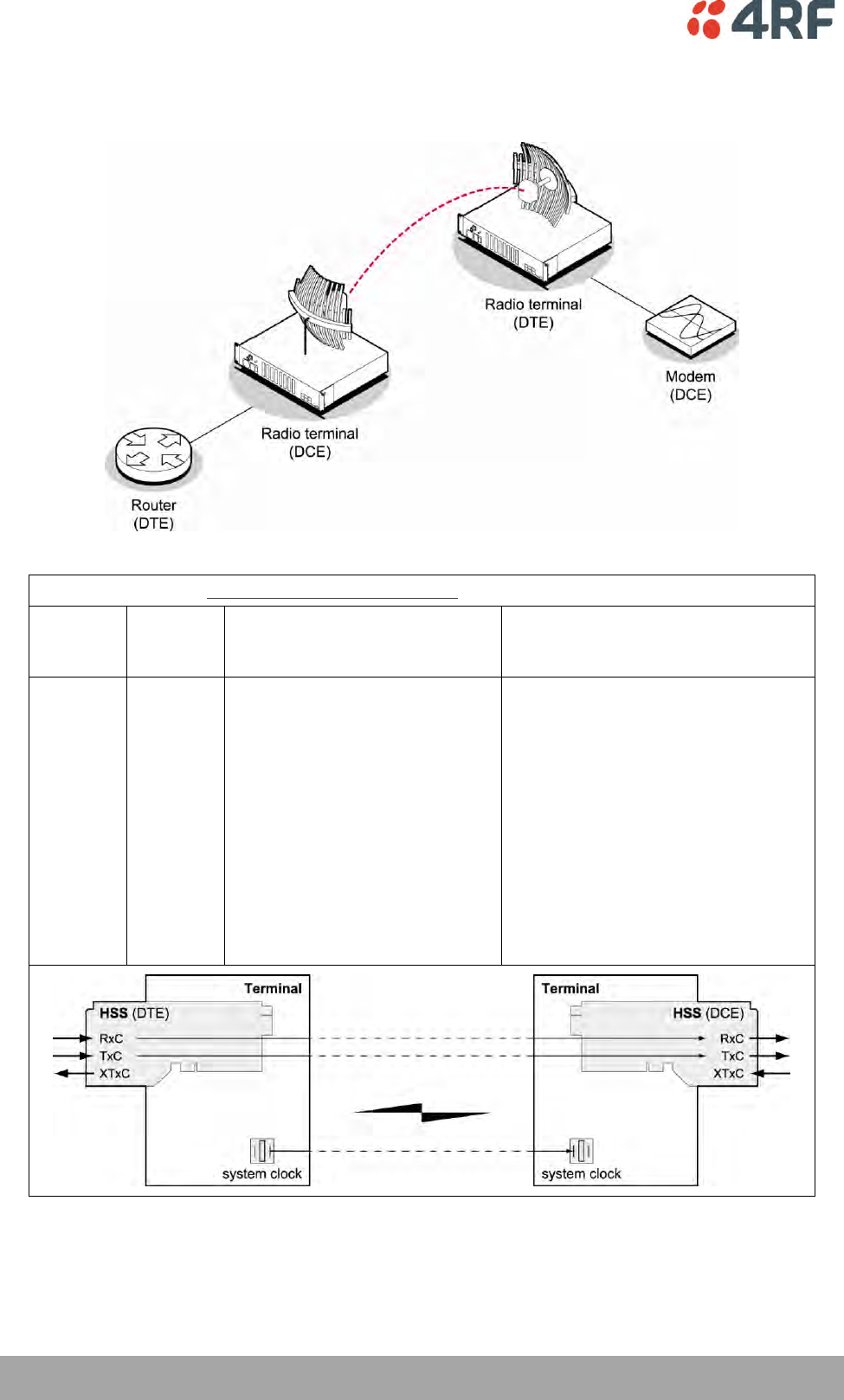
140 | Configuring the Traffic Interfaces
Aprisa XE User Manual
HSS Clocking DTE to DCE ‘Pipe Mode’
DTE to DCE Mode 2: RxC + TxC - 56 kbit/s overhead (Pass-through clocking)
DTE
clocks
used
DCE
clocks
used
Clock passing
Comment
RxC and
TxC
RxC and
TxC
56 kbit/s of overhead is used to
transport RxC and TxC from HSS
DTE to HSS DCE.
This is the preferred dual external
clock system.
Both clocks travel in the same
direction from DTE to DCE. This
mode is used when it is important
that the externally supplied RxC and
TxC are maintained independently.
This is almost only required in
cascaded (that is, multi-link)
networks.
This mode cannot be used in
conjunction with any interface
conversion to / from X.21.
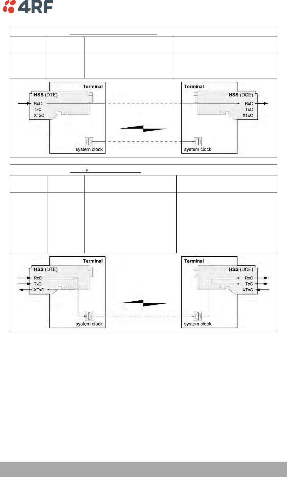
Configuring the Traffic Interfaces | 141
Aprisa XE User Manual
DTE to DCE Mode 3: RxC (X.21) - 40 kbit/s overhead (Pass-through clocking)
DTE clocks
used
DCE clocks
used
Clock passing
Comment
RxC
RxC
40 kbit/s of overhead used to
transport RxC from the DTE to
DCE.
Preferred option for X.21.
DTE to DCE Mode 6: RxC RxC - No overhead (Primary/ Secondary Master clocking)
DTE clocks
used
DCE clocks
used
Clock passing
Comment
RxC and
TxC
RxC and
TxC
The DTE XTxC is derived from
the RxC and is used to generate
the terminal external clock.
The DCE generates RxC and TxC
from the terminal clock.
HSS becomes the External master
clock, avoiding explicit clock
passing, but foregoing the use of
passing a clock in either direction
(Modes 1, 5).
The DTE HSS card must be set as
the External clock for the
terminal.
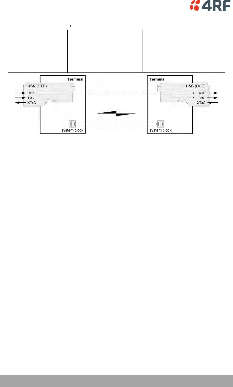
142 | Configuring the Traffic Interfaces
Aprisa XE User Manual
DTE to DCE Mode 7: RxC RxC - 40 kbit/s overhead (Pass-through clocking)
DTE clocks
used
DCE clocks
used
Clock passing
Comment
RxC and
TxC
RxC and
TxC
40 kbit/s of overhead used to
transfer RxC from the DTE to
the DCE RxC and TxC.
Receiver derived clock system.
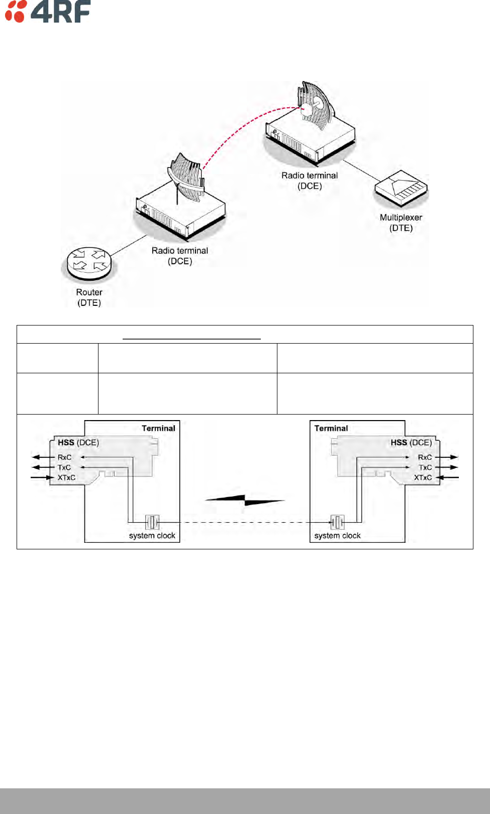
Configuring the Traffic Interfaces | 143
Aprisa XE User Manual
HSS Clocking DCE to DCE ‘Cloud Mode’
DCE to DCE Mode 0: Internal clocks – No overhead (internal clocking)
DCE clocks
used
Clock passing
Comment
RxC, TxC,
XTxC
Both RxC and TxC are derived from
the terminal clock.
Default setting. All clocks sourced
internally. XTxC will be used if it is
detected.
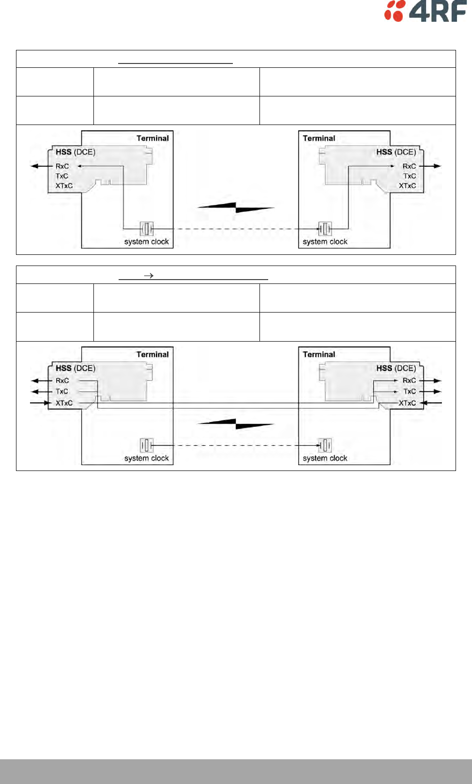
144 | Configuring the Traffic Interfaces
Aprisa XE User Manual
DCE to DCE Mode 4: RxC (X.21) - No overhead (internal clocking)
DCE clocks
used
Clock passing
Comment
RxC
RxC is derived from the terminal
clock.
Suggested for X.21 Cloud Configuration.
Single clock X.21 system.
DCE to DCE Mode 5: XTxC RxC - 40 kbit/s overhead (Pass-through clocking)
DCE clocks
used
Clock passing
Comment
RxC, TxC,
XTxC
XTxC is transported to RxC and TxC in
both directions

Cross Connections | 145
10. Cross Connections
Embedded Cross Connect Switch
The embedded cross-connect switch distributes capacity to each of the interfaces.
Traffic can be distributed to any of the possible 32 interface ports as well as the integrated Ethernet
interface. This provides the flexibility to reconfigure traffic as the network demand changes, or groom
user traffic onto E1 / T1 bearers between equipment.
The maximum number of simultaneous cross connections per terminal is 256. During cross connection
activation, a progress bar shows the number of ports that have activated.
Link Capacity Utilization
Cross connections are able to utilize all of the available capacity of the link on lower capacity radio links
(< 2048 kbit/s gross capacity, i.e. up to 500 kHz, 16 QAM). However, as higher capacity radio links
allocate bandwidth for E1 / T1 timeslot connections on 64 kbit/s boundaries, some capacity may be
unusable (< 64 kbit/s).
The Cross Connections Application
The Cross Connections application is a software application that is used to:
manage the cross connections switches within the terminals
create cross connections between the traffic interface ports within one terminal or between the
near end and far end terminals via the radio bearer
create cross connections between symmetrical traffic interface ports with the symmetrical
connection wizard
get the current cross connection configuration from the terminal
send and activate the cross connection configuration
save and load configuration files
The Cross Connections System Requirements
The Cross Connections application requires the following minimum PC requirements:
1024 x 768 screen resolution
Ethernet interface
Java Virtual Machine
146 | Cross Connections
Aprisa XE User Manual
Installing the Cross Connections Application
The Cross Connections application is usually started directly from SuperVisor without the need for
installation.
However, if you want to use the Cross Connections application offline (without any connection to the
terminals), you can install it on your PC. Working offline enables you to simulate new cards or terminal
capacities. The cross connections can then be configured and the resulting configuration file saved for
later deployment.
To install the Cross Connections application on your PC, navigate to the Cross Connect directory on the
supplied CD and copy the application (ccapp_exe_x_x_x.jar where x is the version) to a suitable place on
your PC hard disk.
Your PC 'File Types' must associate a *.jar file with the Executable Jar File so that when the *.jar file is
clicked on (or double clicked on), it will be executed with Javaw.exe. If clicking on (or double clicking on)
the jar file does not bring up the Cross Connections application, the 'File Types' needs to be setup in your
PC.
Go to 'My Computer / Tools / Folder Options / File Types’ and click 'New'.
Type 'Jar' in the 'File Extension' box and click OK.
Click 'Change' and 'Select a program from a list'
Select 'Javaw.exe' and click OK.
Opening the Cross Connections Application
To open the Cross Connections application from within SuperVisor:
Select Link > Interface > Cross Connections
To open the Cross Connections application without SuperVisor:
Navigate to the installed cross connections application file C-capp_exe_8_6_7.jar and double click on it.
Note: This assumes that you have copied the cross connections application to your PC so you can work
offline (without any connection to the terminals).
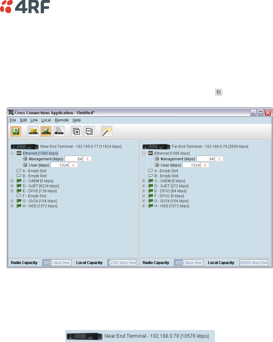
Cross Connections | 147
The Cross Connections Page
The Cross Connections page is split into two panes with each pane displaying one terminal. The local
terminal is displayed in the left pane and the remote terminal is displayed in the right pane.
The local terminal is defined as the terminal that SuperVisor is logged into (not necessarily the near end
terminal).
The cards displayed depend on the type of cards and where they are inserted in the chassis.
To view all the ports for each interface card, click on the expand all ports button .
Tool Tips are available by holding the mouse pointer over objects on the screen.
Total Assigned Link Capacity
The current total assigned capacity (radio link and drop and insert) is shown (in kbit/s) beside the
terminal name and IP address:
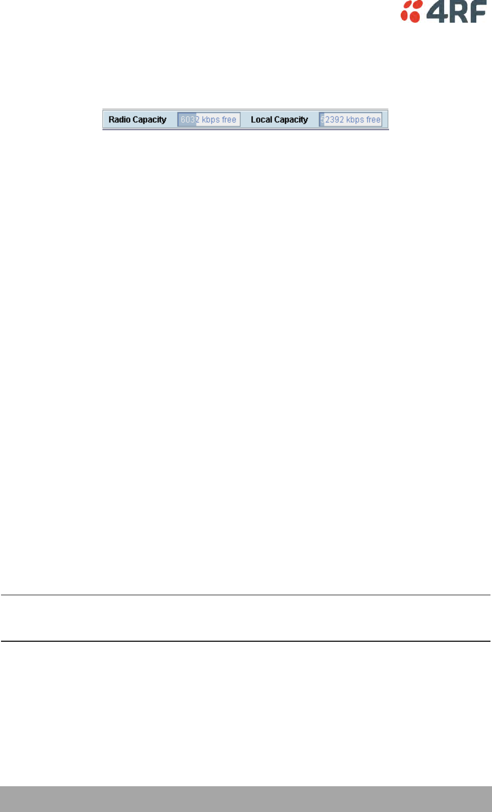
148 | Cross Connections
Aprisa XE User Manual
Radio Link and Local Drop And Insert Capacity
At the bottom of the Cross Connections page, the capacity pane displays the Radio and Local drop and
insert capacities for both the local and remote terminals.
The Radio Capacity field shows the available radio link capacity (6032 kbit/s shown) and the shaded bar
graph shows the capacity used for cross connections over the radio link (2600 kbit/s) between the
terminals as a percentage of the total capacity of the radio link (30 % used).
The total capacity of the radio link is determined by the channel size and the modulation type of the radio
link.
The Local Capacity field shows the available capacity for local or drop and insert cross connections (52392
kbit/s shown) and the shaded bar graph shows the capacity used for local cross connections (4512 kbit/s)
as a percentage of the total local capacity (7 % used).
The total local capacity is 65536 kbit/s minus the used radio capacity.
Tool tip messages show the breakdown of the radio and local capacity usage:
The following is an example of the messages shown:
Radio Capacity
Radio Bandwidth Usage (over the air)
8632 kbit/s total
2600 kbit/s used (30%) of total radio capacity
6032 kbit/s free
Local Capacity
Local capacity usage (for connecting ports on the same terminal)
65536 kbit/s total
8632 kbit/s reserved for radio (13%) of total local capacity
4512 kbit/s used for local (7%) of total local capacity
52392 kbit/s free
Tip: On a screen set to 1024 by 768 resolution, this capacity information may be obscured by the task bar
if the Windows task bar is docked at the bottom of the screen. To view the capacity pane clearly, either
shift the task bar to another screen edge, make it auto-hide, or increase the screen resolution.
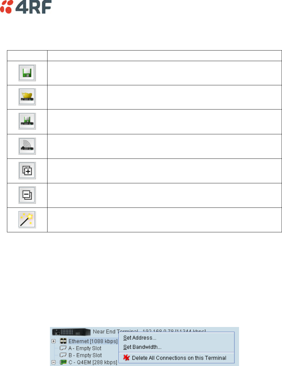
Cross Connections | 149
Cross Connections Toolbar
The cross connections toolbar has buttons for commonly-used functions.
Button
Explanation
Saves the cross connection configuration file to disk. The button turns amber when
you have made changes that have not yet been saved.
Gets the cross connection configuration from the local and remote terminals.
Saves the cross connection configuration to the local and remote terminals. The
button turns amber when you have made changes that have not yet been sent to
the terminal.
Activates the cross connections on the local and remote terminals. Turns amber
when there are cross connections that have been sent but not yet activated.
Expands all the ports for all the interface cards.
Collapses all the ports for all the interface cards.
Opens the symmetrical connections wizard.
Setting the Terminal's IP Address
If the Cross Connections application is launched from SuperVisor, the terminal IP addresses are set
automatically by SuperVisor, but if the application is launched from your PC independent of SuperVisor,
you will need to set the application Local and Remote IP addresses to the addresses of the Local and
Remote terminals you wish to connect to.
To set the application local or remote IP address:
1. Right-click over the terminal name or IP address and select Set Address.
2. Select Local or Remote > Set Address
3. Enter the IP address of the terminal in the dialog box and click OK.
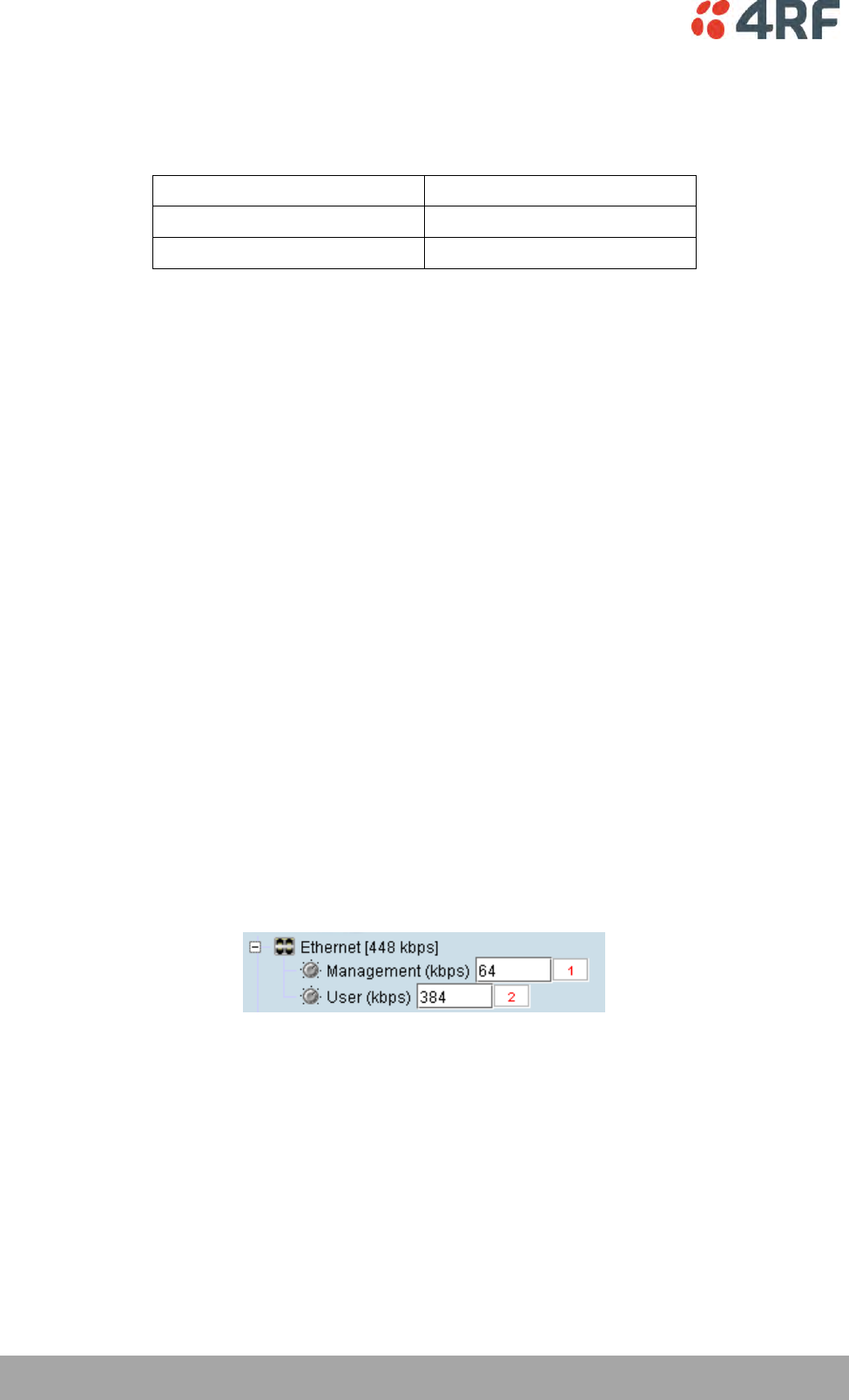
150 | Cross Connections
Aprisa XE User Manual
Management and User Ethernet Capacity
The maximum ethernet capacity of an Aprisa XE terminal is dependant on the motherboard version:
Motherboard Version
Maximum Ethernet Capacity
Rev C
32768 kbit/s
Rev D
49152 kbit/s
The maximum ethernet capacity available is the lesser of the maximum ethernet capacity or the available
radio link capacity.
The management ethernet capacity and user ethernet capacity must be identical on both terminals for the
ethernet link to work correctly.
Management Ethernet Capacity
A management ethernet cross connection between the local and remote terminals is created
automatically using the default capacity of 64 kbit/s (connection number = 1). This connection is
essential for remote terminal management communication.
The minimum management ethernet capacity requirement for correct management operation over the
radio link is 8 kbit/s but if the terminal in on a network with large numbers of broadcast packets, the
management may not be able to function.
The management capacity must be set in multiples of 8 kbit/s and the maximum assignable is 64 kbit/s.
User Ethernet Capacity
A user ethernet cross connection between the local and remote terminals is created automatically using
the default capacity of 0 kbit/s (connection number = 2).
The user ethernet capacity must be set in multiples of 8 kbit/s.
The maximum user ethernet capacity available is the maximum ethernet capacity available minus the
management ethernet capacity setting.
To set the management ethernet or the user ethernet capacity:
Enter the required kbit/s in the local terminal capacity field. The associated remote terminal capacity
field will update automatically.
The red numbers, in the mapping connection boxes, are known as connection numbers and are allocated
automatically by the Cross Connections application.
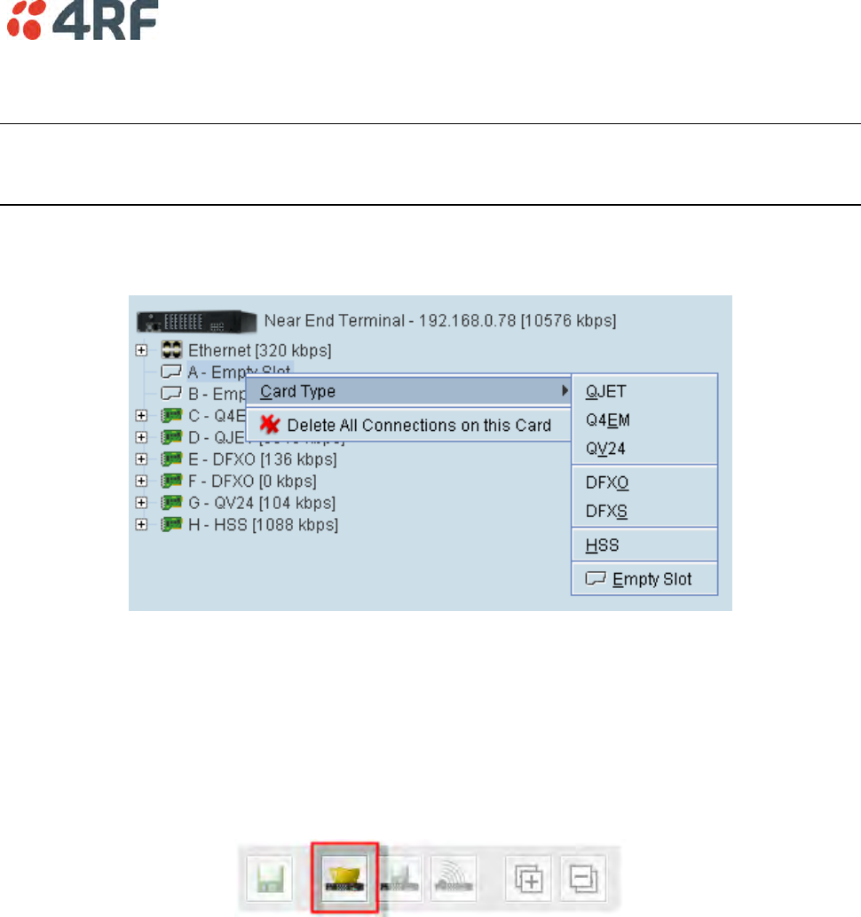
Cross Connections | 151
Setting Card Types
Note: You only need to do this when creating configurations offline (that is, there is no connection to the
terminal). When you are connected to the terminal, the Cross Connections application automatically
detects the card types fitted in the terminal slots.
You can specify the card type for any of the slots (A-H).
1. Right-click a slot.
2. Select Card Type and then select the interface card.
Getting Cross Connection Configuration from the Terminals
You can get the entire existing cross connection configuration from the terminals.
1. Download the existing cross connections (if any) from the local and remote terminals by clicking ‘Get
cross connection configuration from terminal’.
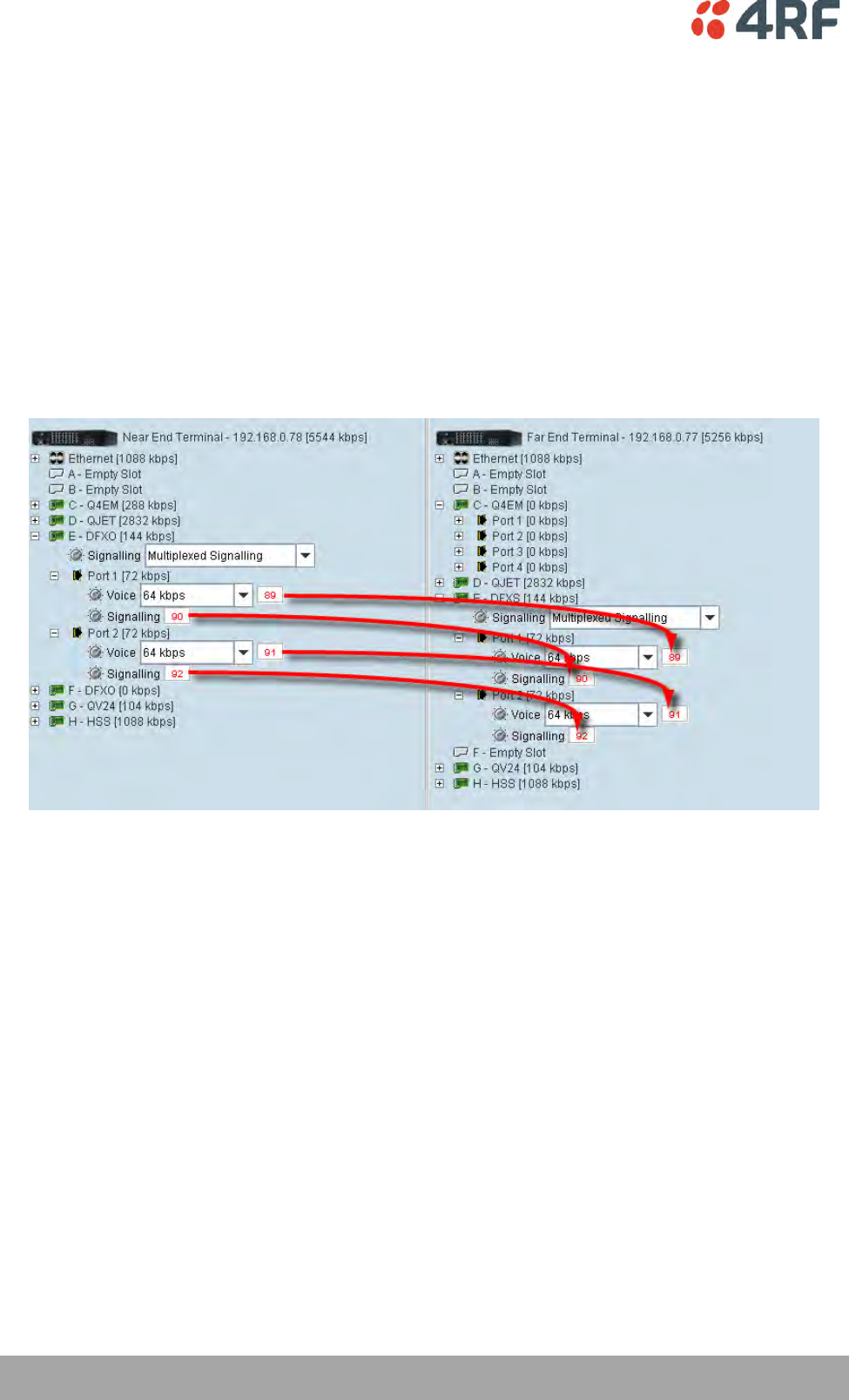
152 | Cross Connections
Aprisa XE User Manual
Creating Cross Connections
Point to point cross connections
Three examples of point to point cross connections are shown below:
Example 1
One 2 wire DFXO interface on the near end terminal slot E port 1 is cross connected via the radio link to a
2 wire DFXS on the far end terminal slot E port 1. This cross connection includes the four bits of signalling
(ABCD bits) but as the DFXO / DFXS signalling is configured for 'multiplexed', the four bits are multiplexed
into one bit over the radio link. This cross connection uses 72 kbit/s of radio link capacity, 64 kbit/s for
the voice and 8 kbit/s for the signalling bit.
The port 2s of the same DFXO / DFXS cards are cross connected using the same method.
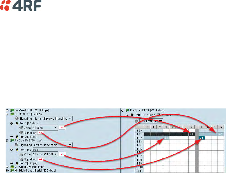
Cross Connections | 153
Example 2
One 2 wire DFXS interface on the near end terminal slot E port 1 is cross connected via the radio link to a
framed E1 on the far end terminal slot D port 1 in timeslot 1. This cross connection includes four bits of
signalling as the DFXS signalling is configured as 'non-multiplexed signalling' (ABCD bits). This cross
connection uses 96 kbit/s of radio link capacity, 64 kbit/s for the voice and 32 kbit/s for the signalling
bits.
Another 2 wire DFXS interface on the near end terminal slot F port 1 is cross connected via the radio link
to a framed E1 on the far end terminal slot D port 1 in timeslot 2. This cross connection includes one bit of
signalling as the DFXS signalling is configured in '4 wire compatible' mode (A bit only). This cross
connection uses 40 kbit/s of radio link capacity, 32 kbit/s for the ADPCM voice and 8 kbit/s for the
signalling bit.
Example 3
One 2 wire DFXS interface on the near end terminal slot E port 1 is cross connected via the radio link to a
framed E1 on the far end terminal slot D port 1 in timeslot 1. This cross connection includes one bit of
signalling as the DFXS signalling is configured as 'multiplexed' signalling. This cross connection uses
72 kbit/s of radio link capacity, 64 kbit/s for the voice and 8 kbit/s for the signalling bit.
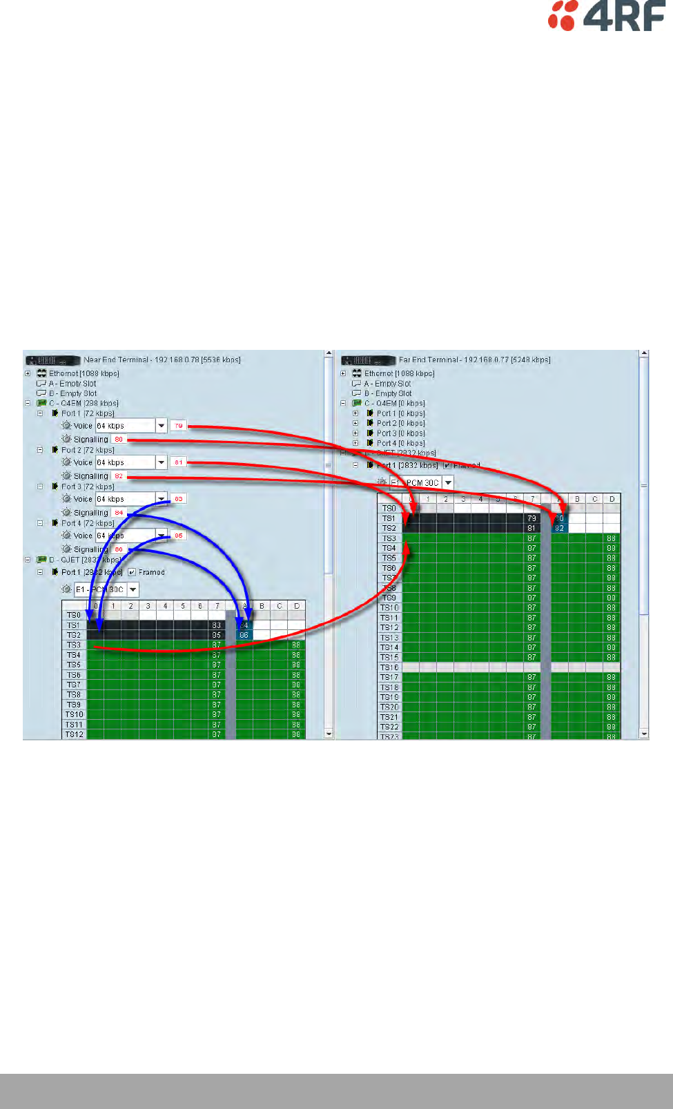
154 | Cross Connections
Aprisa XE User Manual
Local Drop and Insert Cross Connections
An example of a local drop and insert cross connection is shown below:
Two 4 wire E&M interfaces on the near end terminal slot C ports 3 & 4 are dropped out of a framed E1 on
the near end terminal slot D port 1 in timeslots 1 & 2. This cross connection includes one bit of signalling
(A bit).
Another two 4 wire E&M interfaces on the near end terminal slot C ports 1 & 2 are inserted into the radio
link to a framed E1 on the far end terminal slot D port 1 in timeslots 1 & 2. This cross connection includes
one bit of signalling (A bit).
The remaining framed E1 on the near end terminal slot D port 1 timeslots are transported over the radio
link to the framed E1 on the far end terminal slot D port 1. This cross connection includes four bits of
signalling (ABCD bits).
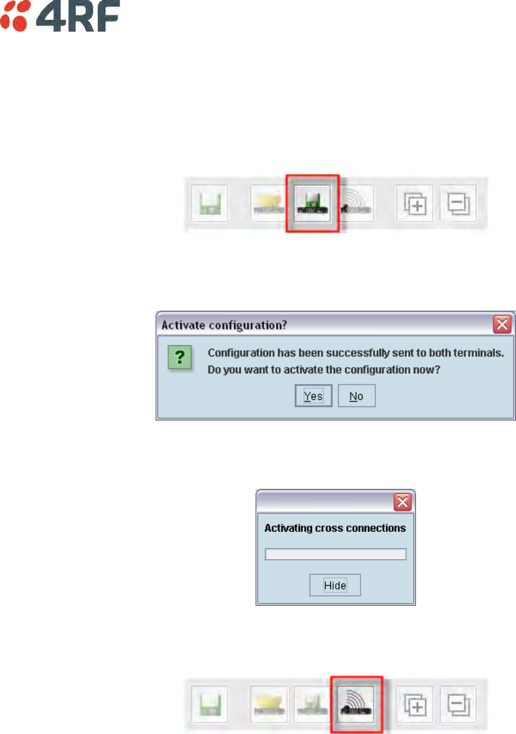
Cross Connections | 155
Sending Cross Connection Configuration to the Terminals
You can send the entire cross connection configuration to the terminals.
1. To send the new cross connection configuration into the terminals, click ‘Send cross connection
configuration to terminal’.
2. When the transfer is successfully complete, a message appears asking if you want to activate the
configuration now.
If you click Yes, a message appears showing the activation progress.
If you click No, you can activate the new cross connection configuration later by clicking ‘Activate
cross connection configuration’.
Saving Cross Connection Configurations
You can save the entire cross connection configuration to file so that you can restore it to the same link (if
this is ever required), or transfer it to another link if you want them to be identical.
1. Click on ‘Save cross connection configuration file to disk’ or select File > Save.
2. Navigate to the directory where you want to save the file, enter the filename in the dialog box and
then click Save.
3. Once you have specified a filename and a directory save any further changes by clicking Save.
Using Existing Cross Connection Configurations
To load a previously-saved cross connection configuration from an existing file:
1. Select File > Open.
2. Navigate to the file and select it, and then click Open.
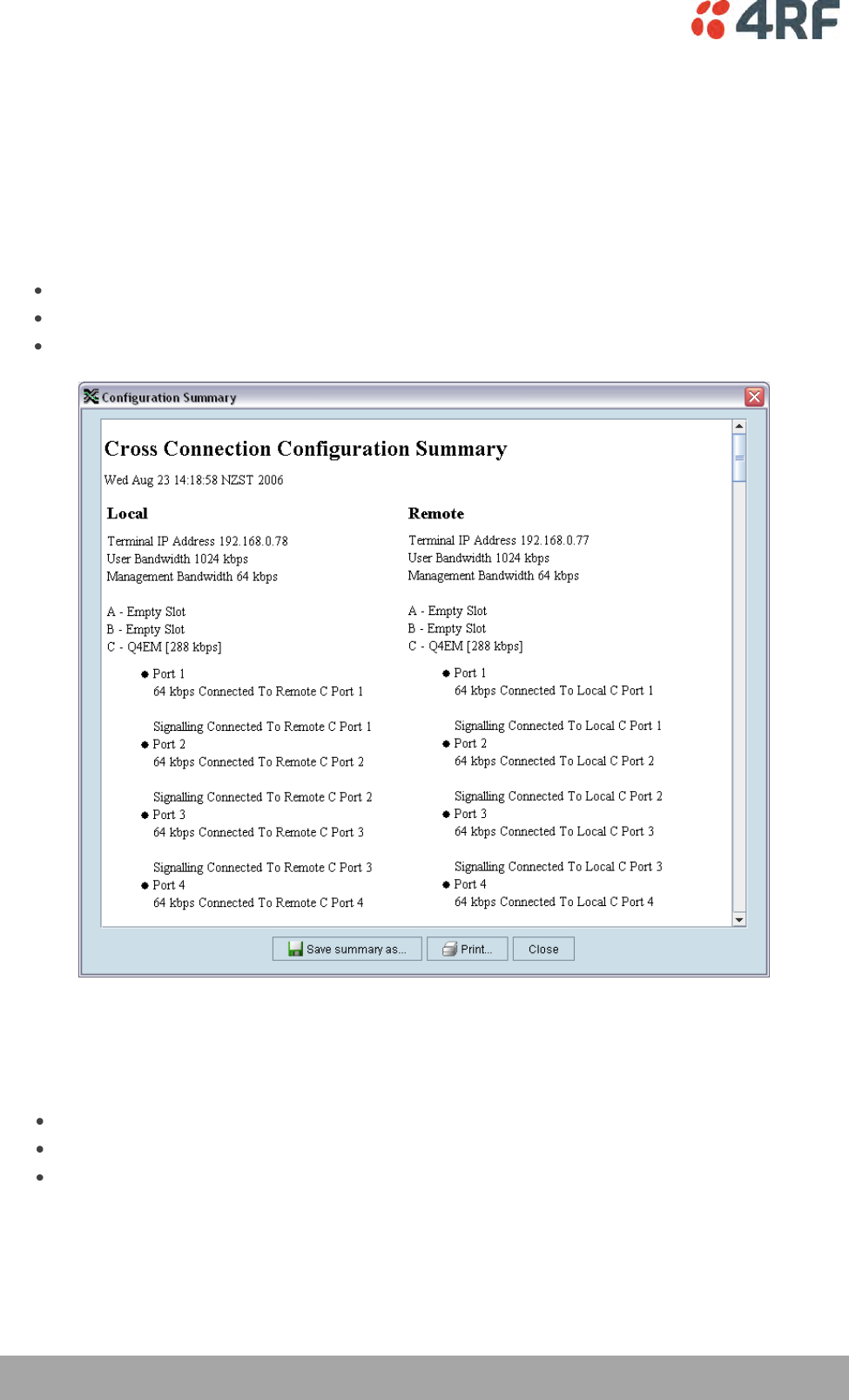
156 | Cross Connections
Aprisa XE User Manual
Printing the Cross Connection Configuration
You can print out a summary of the cross connection configuration so that you can file it for future
reference. Using the printout, you can recreate the cross connection configuration.
If you don't have the configuration saved to disk see ‘Saving cross connection configurations’ on page 155,
or use it to review the cross connections without connecting to the terminal.
The cross connection configuration summary shows information for the local and remote terminals such
as:
The IP address and terminal name
The interface card fitted in each slot
How the ports are configured
To preview the cross connection configuration summary:
Select File > Preview Configuration Summary.
In this dialog box you can:
Save the summary to disk (as an HTML file) by clicking Save Summary As.
Print the summary by clicking Print.
Copy and paste the information into another application (for example, spreadsheet, email, and
word processor) by right-clicking over the summary and selecting Select All. Then right-click over
the summary again and select Copy.
To print the cross connection configuration summary:
Select File > Print Configuration Summary.
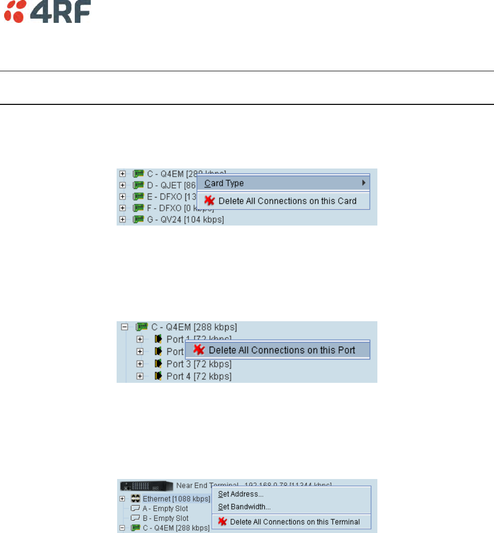
Cross Connections | 157
Deleting Cross Connections
Note: It is not possible to delete the management and user Ethernet cross connections. These are made
automatically and are required for correct terminal operation.
To delete cross connections for an interface card:
1. Right-click over an interface card.
2. Select Delete All Connections on this Card.
To delete the cross connections associated with a particular port:
1. Right-click over a port.
2. Select Delete All Connections on this Port.
To delete all the cross connections for a terminal:
1. Right-click over the terminal name and IP address.
2. Select Delete All Connections on this Terminal.
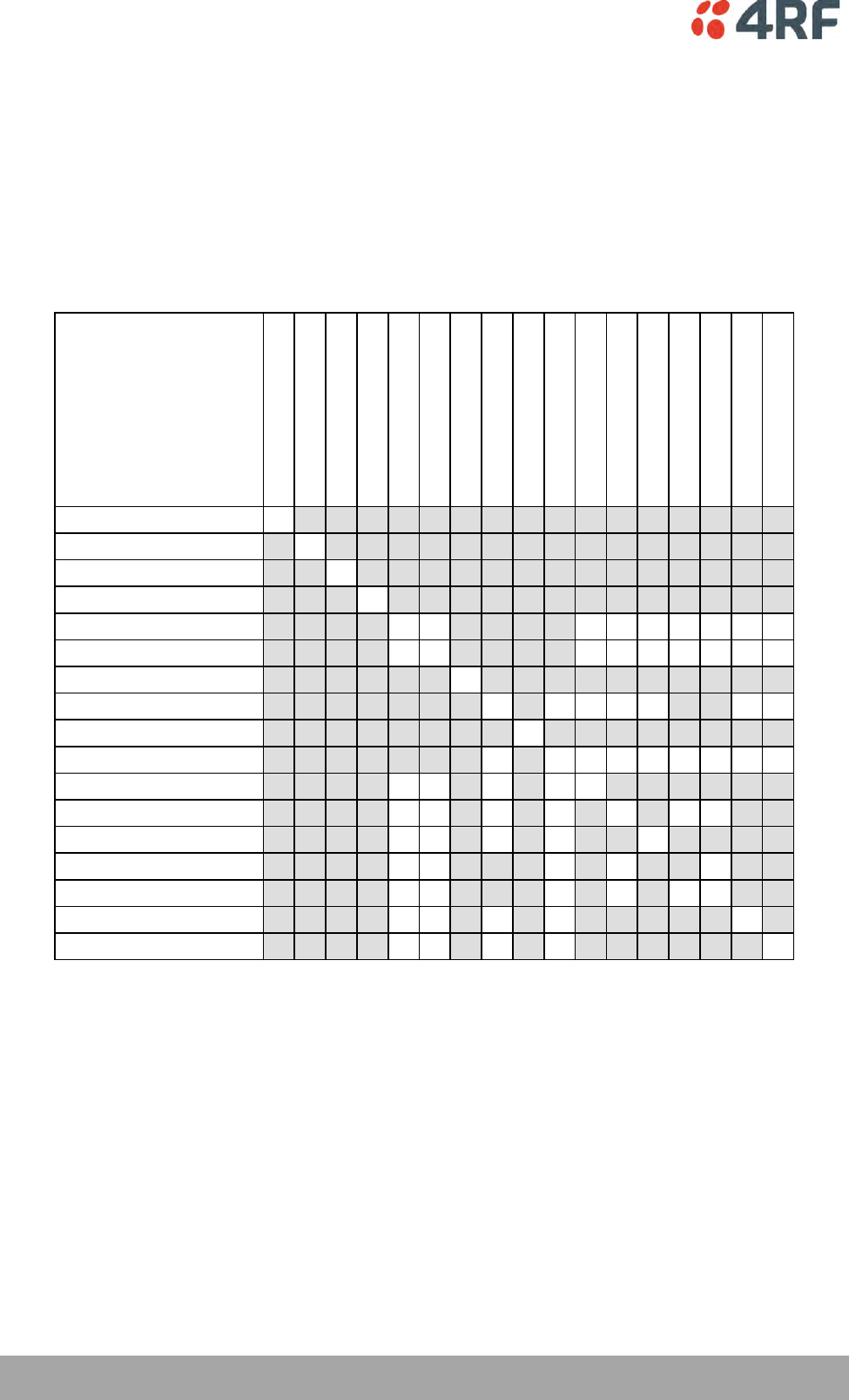
158 | Cross Connections
Aprisa XE User Manual
Configuring the Traffic Cross Connections
Once you have configured the interface cards (see ‘Configuring the traffic interfaces’ on page 91), you can
configure the traffic cross connections between compatible interfaces.
Compatible Interfaces
Cross connections can be made between any compatible interfaces of equal data rates. Compatible
interfaces are shown in the table below:
Ethernet (management)
Ethernet (user)
QJET E1 Unframed
QJET T1 Unframed
QJET E1 Framed PCM 31
QJET E1 Framed PCM 30
QJET T1 SF - PTS
QJET T1 SF - DMS
QJET T1 ESF - PTS
QJET T1 ESF - DMS
Q4EM voice only
Q4EM with E&M
QV24 with signalling
DFXO
DFXS
HSS data
HSS signalling
Ethernet (management)
Ethernet (user)
QJET E1 Unframed
QJET T1 Unframed
QJET E1 Framed PCM 31
QJET E1 Framed PCM 30
QJET T1 SF - PTS
QJET T1 SF - DMS
QJET T1 ESF - PTS
QJET T1 ESF - DMS
Q4EM voice only
Q4EM with E&M
QV24 with signalling
DFXO
DFXS
HSS data
HSS signalling
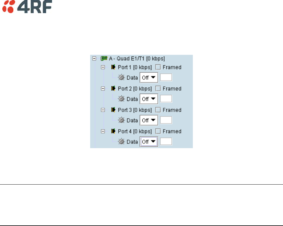
Cross Connections | 159
QJET Cross Connections
Expand the E1 / T1 display by clicking on the relevant icons.
The QJET card can operate in several modes allowing you greater flexibility in tailoring or grooming
traffic. The Data type selection are Off, E1, or T1 rates.
Note: An unframed E1 / T1 port requires 5 bits (or 40 kbit/s) of overhead traffic per port for
synchronization.
An unframed E1 port with 2048 kbit/s of traffic requires 2088 kbit/s of link capacity.
An unframed T1 port with 1544 kbit/s of traffic requires 1584 kbit/s of link capacity.
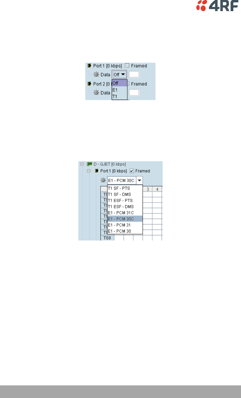
160 | Cross Connections
Aprisa XE User Manual
For each port that you want to put into service, choose the required mode (either Unframed or Framed):
Unframed Mode
Leave the Framed checkbox unticked.
Select the required Data type from the drop-down list E1 or T1.
Local drop and insert connections are not possible between Unframed E1 / T1 ports.
Framed Mode
Tick the Framed checkbox.
Select the required framed mode from the drop-down list:
Local drop and insert connections are possible between framed E1 ports on the same interface card or E1
ports on different interface cards.
Local drop and insert connections are possible between framed T1 ports on the same interface card or T1
ports on different interface cards.
Local drop and insert connections are not possible between framed E1 ports and framed T1 ports.
Cross Connections | 161
E1 Framed Modes
Framed Mode
Description
E1 – PCM 30
Provides 30 timeslots to transport traffic. Timeslot 16 carries channel
associated signalling data (CAS).
E1 – PCM 31
Provides 31 timeslots to transport traffic. Timeslot 16 can be used for
common channel signalling or to transport traffic.
E1 – PCM 30C
Same as E1 – PCM 30 mode but supports CRC-4.
E1 – PCM 31C
Same as E1 – PCM 31 mode but supports CRC-4.
E1 CRC-4 (cyclic redundancy check) is used to ensure correct frame alignment and also used to gather E1
performance statistics e.g. Errored Seconds (ES), Severely Errored Seconds (SES).
The first three bits of timeslot 0 NFAS (bits 0,1 & 2) and all of timeslot 0 FAS are not transported across
the link, but rather terminated and regenerated at each terminal.
The last five bits of timeslot 0 NFAS (bits 3 – 7) are the National Use Bits (NUBs) which can be cross
connected locally or over the link.
E1 - PCM 30 mode
E1 - PCM 30 modes are used when access to the signalling bits (ABCD) is required, for example:
Splitting a PCM 30 E1 into two separate PCM 30 E1s
Cross connecting signalling from DFXS, DFXO or Q4EM interfaces into an PCM 30 E1
Drop and Insert connections between PCM 30 E1s
In PCM 30 / PCM 30C mode, the timeslot table left column is used to map timeslot bits and the timeslot
table right column is used to map CAS bits (ABCD) for signalling. Timeslot 16 is reserved to transport the
CAS multi frame.
One use of this mode is to connect the 4 wire E&M interfaces to third-party multiplexer equipment over
the E1 interface using CAS in TS16 to transport the E&M signalling.
To configure this mode correctly, you must have a detailed knowledge of the CAS signalling modes for the
third-party equipment to ensure the signalling bits are compatible and configured to interoperate.
E1 - PCM 31 mode
E1 - PCM 31 modes are used to cross connect timeslots bits without the signalling bits (ABCD).
TS16 can be cross connected between E1 ports (to transport the entire CAS multi frame) or used for
common channel signalling or to transport traffic.
The timeslot table left column is used to map timeslot bits but the timeslot table right column for CAS bits
(ABCD) is not used.
162 | Cross Connections
Aprisa XE User Manual
T1 Framed Modes
Framed Mode
Description
T1 SF - PTS
Provides 24 timeslots to transport traffic using the G.704 12 frame Super
Frame with Pass Thru Signalling (PTS). There is no CRC capability with the
SF.
T1 SF - DMS
Provides 24 timeslots to transport traffic using the G.704 12 frame Super
Frame with DeMultiplexed Signalling (CAS AB bits). There is no CRC
capability with the SF.
T1 ESF - PTS
Provides 24 timeslots to transport traffic using the G.704 24 frame Extended
Super Frame with Pass Thru Signalling (PTS) and CRC.
T1 ESF - DMS
Provides 24 timeslots to transport traffic using the G.704 24 frame Extended
Super Frame with DeMultiplexed Signalling (CAS ABCD bits) and CRC.
T1 SF - PTS mode
T1 SF - PTS mode provides 24 timeslots to transport traffic using the G.704 12 frame Super Frame without
demultiplexing the signalling.
Pass Thru Signalling provides cross connection of the entire framed T1 timeslot between T1 ports
(including the inherent robbed bit signalling). This is the most efficient method of transporting a framed
T1 over the radio link as no additional radio link capacity is required to transport the signalling because
the CAS is not demultiplexed.
To maintain multi frame alignment between two framed T1 ports, a FPS (Frame Pattern Sync) bit is
required to be cross connected between the two framed T1 ports. This FPS bit requires an additional
8 kbit/s of radio link capacity.
The timeslot table left column is used to map timeslot bits but the timeslot table right column for CAS bits
(ABCD) is not used.
T1 SF - PTS mode is used when access to the signalling bits is not required but are transported between
T1s, for example:
Drop and Insert connections between Super Frame T1s or data interfaces
T1 SF – DMS mode
T1 SF – DMS mode provides 24 timeslots to transport traffic using the G.704 12 frame Super Frame with
four state demultiplexed signalling using the AB bits each with a bit rate of 333 bit/s.
DeMultiplexed Signalling allows the cross connection of framed T1 ports to other interface ports e.g. to a
Q4EM or HSS. An additional 8 kbit/s of radio link capacity is required to transport each CAS bit over the
radio link.
The mapping left column is used to map timeslot bits and the timeslot table right column is used to map
the CAS A&B bits for signalling (C&D bits are not used).
T1 SF – DMS mode is used when access to the signalling bits is required, for example:
Cross connecting signalling from a Q4EM interfaces into a 12 frame Super Framed T1.
Drop and Insert connections between Super Framed T1s or data interfaces
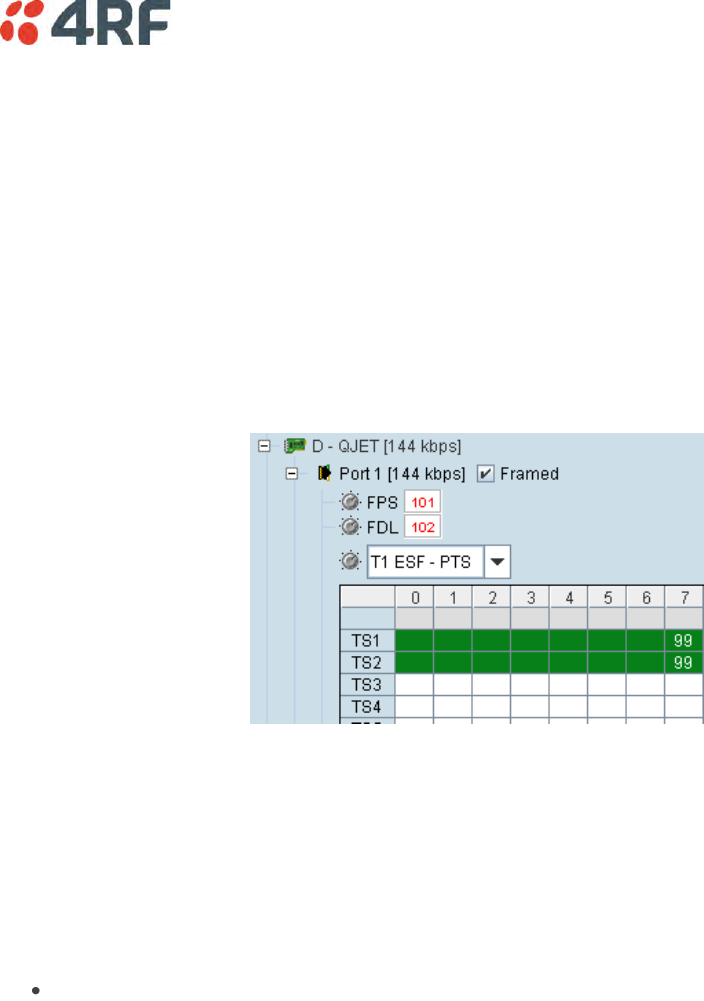
Cross Connections | 163
T1 ESF - PTS mode
T1 ESF - PTS mode provides 24 timeslots to transport traffic using the G.704 24 frame Extended Super
Frame without demultiplexing the signalling.
Pass Thru Signalling provides cross connection of the entire framed T1 timeslot between T1 ports
(including the inherent robbed bit signalling). This is the most efficient method of transporting a framed
T1 over the radio link as no additional radio link capacity is required to transport the signalling because
the CAS is not demultiplexed.
To maintain multi frame alignment between two framed T1 ports, a FPS (Frame Pattern Sync) bit is
required to be cross connected between the two framed T1 ports. This FPS bit requires an additional
8 kbit/s of radio link capacity.
The FDL (Facility Data Link) can be cross connected between the two framed T1 ports if required. This FDL
bit requires an additional 8 kbit/s of radio link capacity.
The timeslot table left column is used to map timeslot bits but the timeslot table right column for CAS bits
(ABCD) is not used.
T1 ESF - PTS mode is used when access to the signalling bits is not required but are transported between
T1s, for example:
Drop and Insert connections between 24 frame Extended Super Framed T1s or data interfaces

164 | Cross Connections
Aprisa XE User Manual
T1 ESF - DMS
T1 ESF - DMS mode provides 24 timeslots to transport traffic using the G.704 24 frame Extended Super
Frame with sixteen state demultiplexed signalling using the ABCD bits each with a bit rate of 333 bit/s.
DeMultiplexed Signalling allows the cross connection of framed T1 ports to other interface ports e.g. to a
Q4EM or HSS. An additional 8 kbit/s of radio link capacity is required to transport each CAS bit over the
radio link.
The FDL (Facility Data Link) can be cross connected between the two framed T1 ports if required. This FDL
bit requires an additional 8 kbit/s of radio link capacity.
The mapping left column is used to map timeslot bits and the timeslot table right column is used to map
the CAS ABCD bits for signalling.
T1 ESF - DMS mode is used when access to the signalling bits is required, for example:
Cross connecting signalling from DFXS, DFXO or Q4EM interfaces into a 24 frame Extended Super
Framed T1 using ‘non-multiplexed’ signalling from the interface.
Drop and Insert connections between 24 frame Extended Super Framed T1s or data interfaces
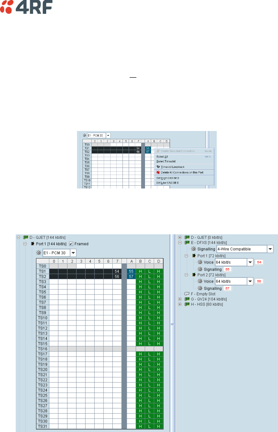
Cross Connections | 165
QJET Spare CAS Bit Control
The Aprisa XE can currently provide E1 CAS to DFXS circuits using the 1 bit '4 wire compatible' signalling
mode (uses the CAS A bit) but to enable some exchange DTIs to operate, the state of the spare CAS bits
sent to the exchange must be preset.
The available CAS bits can be preset to High (1) or Low (0) for the QJET framed modes of E1 - PCM30,
E1 - PCM30C, T1 SF - DMS and T1 ESF – DMS for all timeslots of the port.
To preset the spare CAS bits:
Right click on the CAS bit required to be set.
Select ‘Set High CAS Bit x’ or ‘Set Low CAS Bit x’.
The screen shot shows the standard configuration where the DFXS signalling using 1 bit '4 wire compatible'
signalling mode is mapped to the QJET CAS A bit and the ‘spare’ CAS bits are preset to the standard 1 bit
protocol spare bit pattern of BCD = 101.
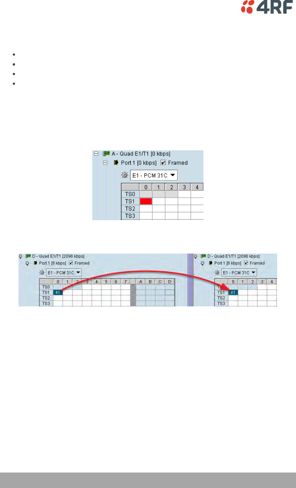
166 | Cross Connections
Aprisa XE User Manual
Selecting and Mapping Bits and Timeslots
This section describes how to select and map:
a single bit
multiple bits
a 64 kbit/s timeslot
multiple timeslots
Selecting a Single Bit
Each timeslot is represented by 8 rectangles (each representing a single bit). Each bit can carry 8 kbit/s.
One or more consecutive bits can be selected in a timeslot if a rate of greater than 8 kbit/s is required.
1. Click on the rectangle that represents the bit you require. It will turn red.
2. Click and drag this bit to the rectangle representing the bit on the interface you want it to be
connected to, and release the mouse button.
The red rectangle will be replaced by the allocated connection number at each interface.
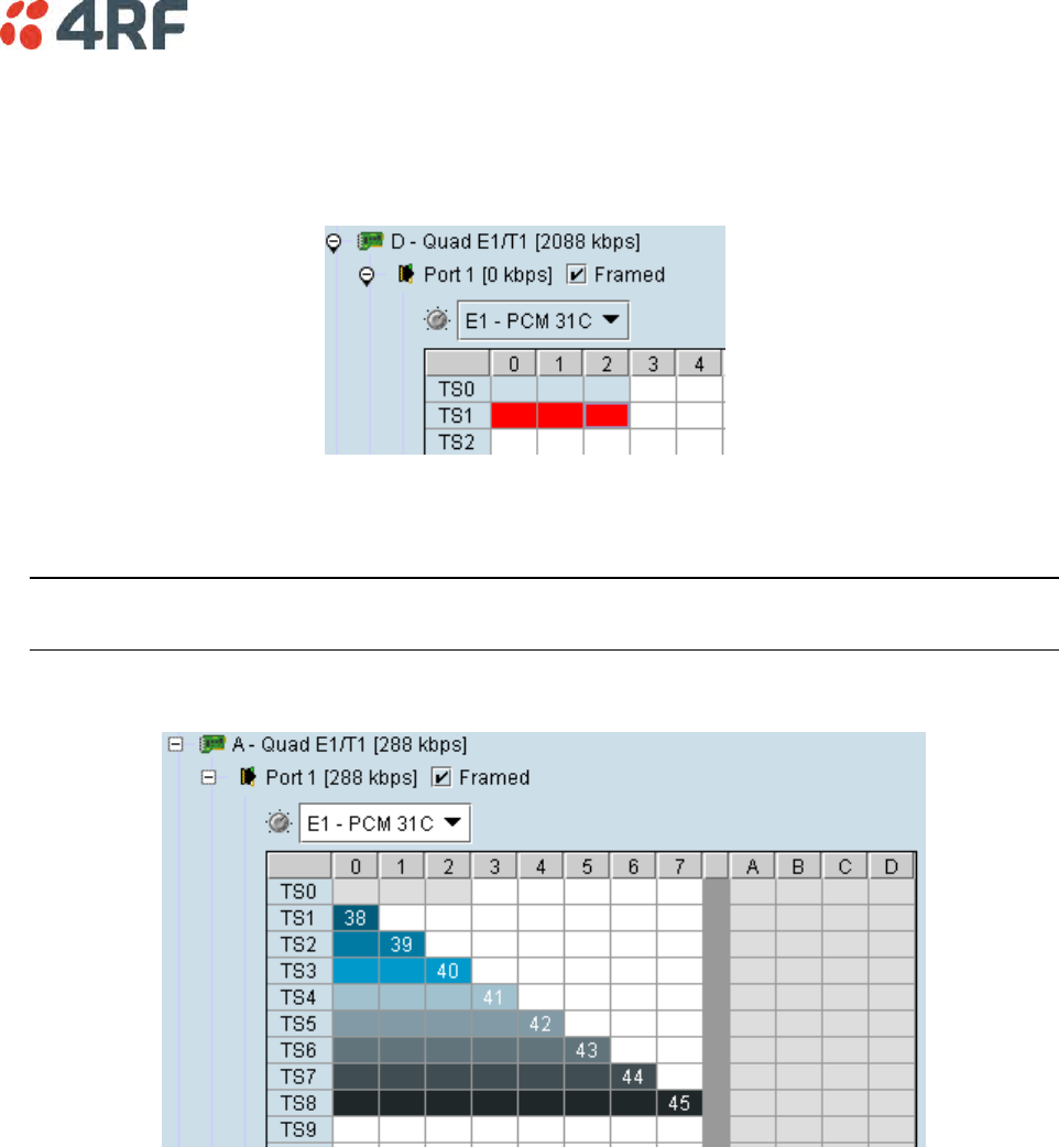
Cross Connections | 167
Selecting Multiple Bits
It is possible to select multiple consecutive bits if circuit capacity of greater than 8 kbit/s is required.
1. Click the first bit, and then hold down the Ctrl key while selecting the remaining bits.
2. Click and drag the whole block by clicking the bit on the left hand side of your selection, and drag to
the required interface. Release the mouse button.
Tip: It is also possible to select multiple bits by holding down the Shift key, and dragging across the
required rectangles.
Differing numbers of bits display in different colors when the cross-connect is completed:
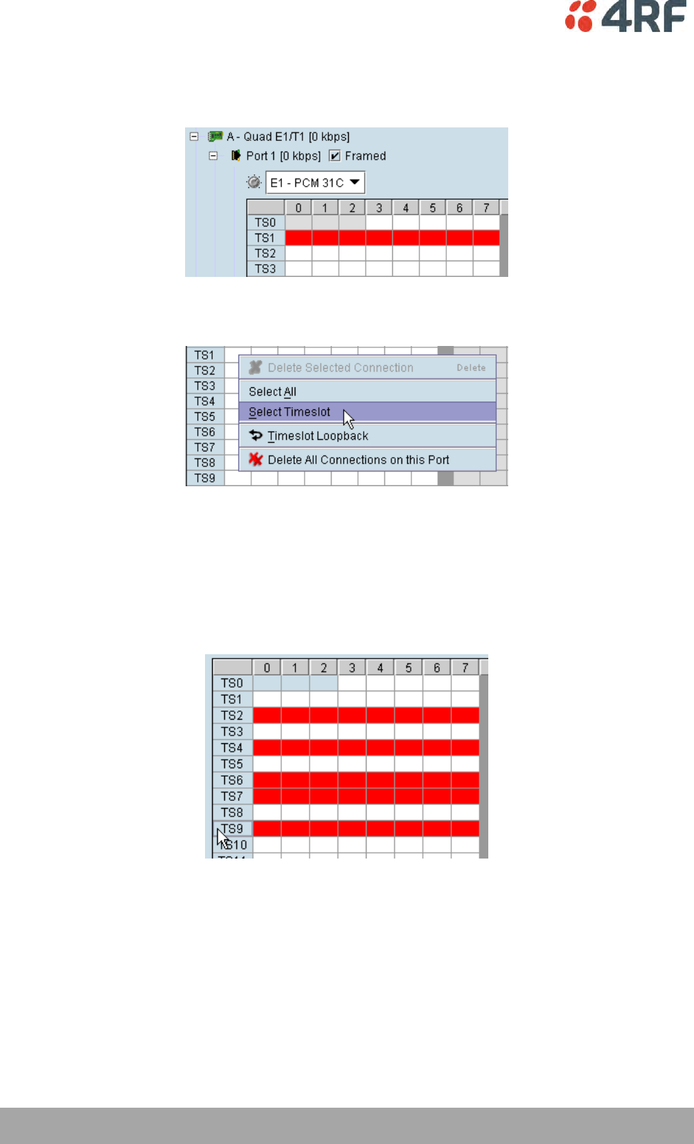
168 | Cross Connections
Aprisa XE User Manual
Selecting a 64 kbit/s Timeslot
1. Click on the TSX timeslot number (where X is the desired timeslot from 1 to 31).
Alternatively, right-click over any of the bits in the timeslot, and click on Select Timeslot.
2. Drag and drop in the normal way to complete the cross connection.
Selecting Multiple Non Consecutive Timeslots
1. Click on one TSn timeslot number (where n is the desired timeslot 1 to 31).
2. Hold down the Ctrl key while clicking on each of the required timeslot numbers.
3. Drag and drop in the normal way to complete the cross connection.
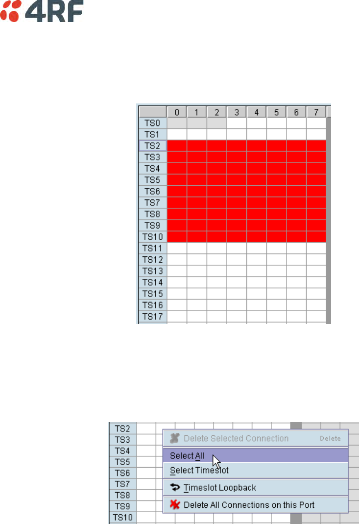
Cross Connections | 169
Selecting Multiple Consecutive Timeslots
1. Click on the first TSn timeslot number (where n is the desired timeslot 1 to 31).
2. Hold down the Shift key while clicking on the last required timeslot number.
3. Drag and drop in the normal way to complete the cross connection.
Selecting All Timeslots in a Port
1. Right-click over any of the rectangles.
2. Click Select All.
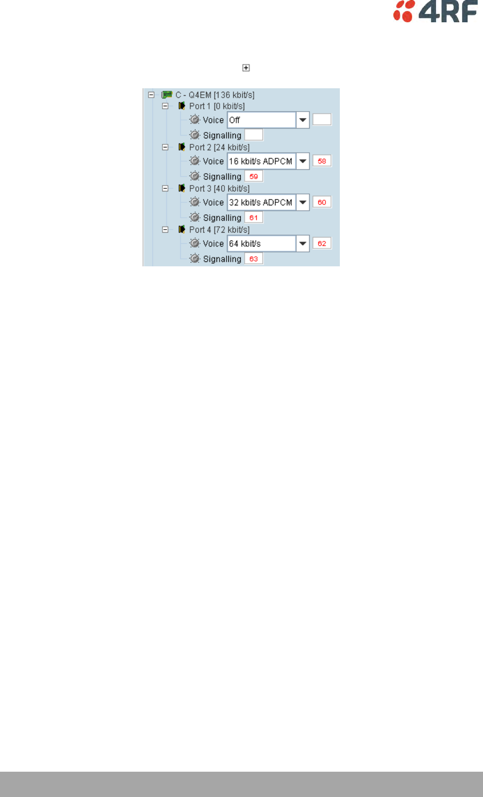
170 | Cross Connections
Aprisa XE User Manual
Q4EM Cross Connections
1. Expand the Q4EM display by clicking the relevant icon.
2. Set the Voice capacity by selecting 16, 24, 32, or 64 kbit/s rates.
3. Drag and drop from the Voice mapping connection box to the required partner interface to create the
voice cross connection.
4. If E&M signalling is required, drag and drop from the Signalling mapping connection box to the
required partner interface to create the E&M cross connection.
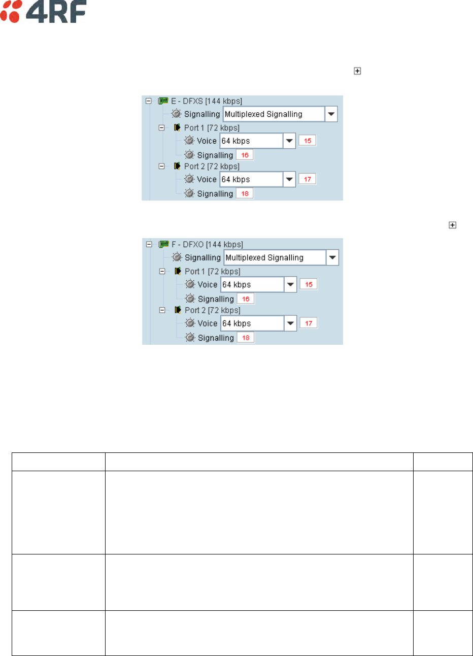
Cross Connections | 171
DFXS and DFXO Cross Connections
1. On one side of the link, expand the DFXS display, as required, by clicking .
2. On the other side of the link, expand the corresponding DFXO display, as required, by clicking .
3. For the DFXS card and corresponding DFXO card, select the Signalling type as required, according to
the table below. The CAS signalling between DFXO / DFXS interfaces uses 4RF proprietary allocation of
control bits.
The Signalling type affects both ports of the DFXO / DFXS interface. If a mixture of signalling types is
required, then multiple DFXO / DFXS cards are needed.
Signalling
Application
Overhead
Multiplexed
(default)
Multiplexers the four ABCD bits from the interface into a single 8
kbit/s channel.
Use when interworking DFXO to DFXS, between an XE and a SE
radio or when limited bandwidth is available.
This signalling type cannot be used for interworking between
framed E1 / T1 and voice interfaces.
8 kbit/s
Non-multiplexed
Transports each of the four ABCD bits in separate 8 kbit/s
channels.
Use when interworking DFXO to DFXS, or when signalling bits are
mapped into an E1 / T1 timeslot.
32 kbit/s
4 wire compatible
1 bit CAS using only the A bit in both directions of transmission.
Use when interworking the DFXS to Q4EM, DFXO to Q4EM, DFXS to
DFXS or DFXS to QJET for DTI circuits.
8 kbit/s
4. Set the Voice capacity and create the Voice connection by dragging and dropping between the
mapping connection boxes of the DFXO and DFXS corresponding ports.
5. Link the Port Signalling connection by dragging and dropping between the mapping connection boxes
of the DFXO and DFXS corresponding ports. The DFXO / DFXS control signals (off hook, ring, etc) will
not function without this connection.
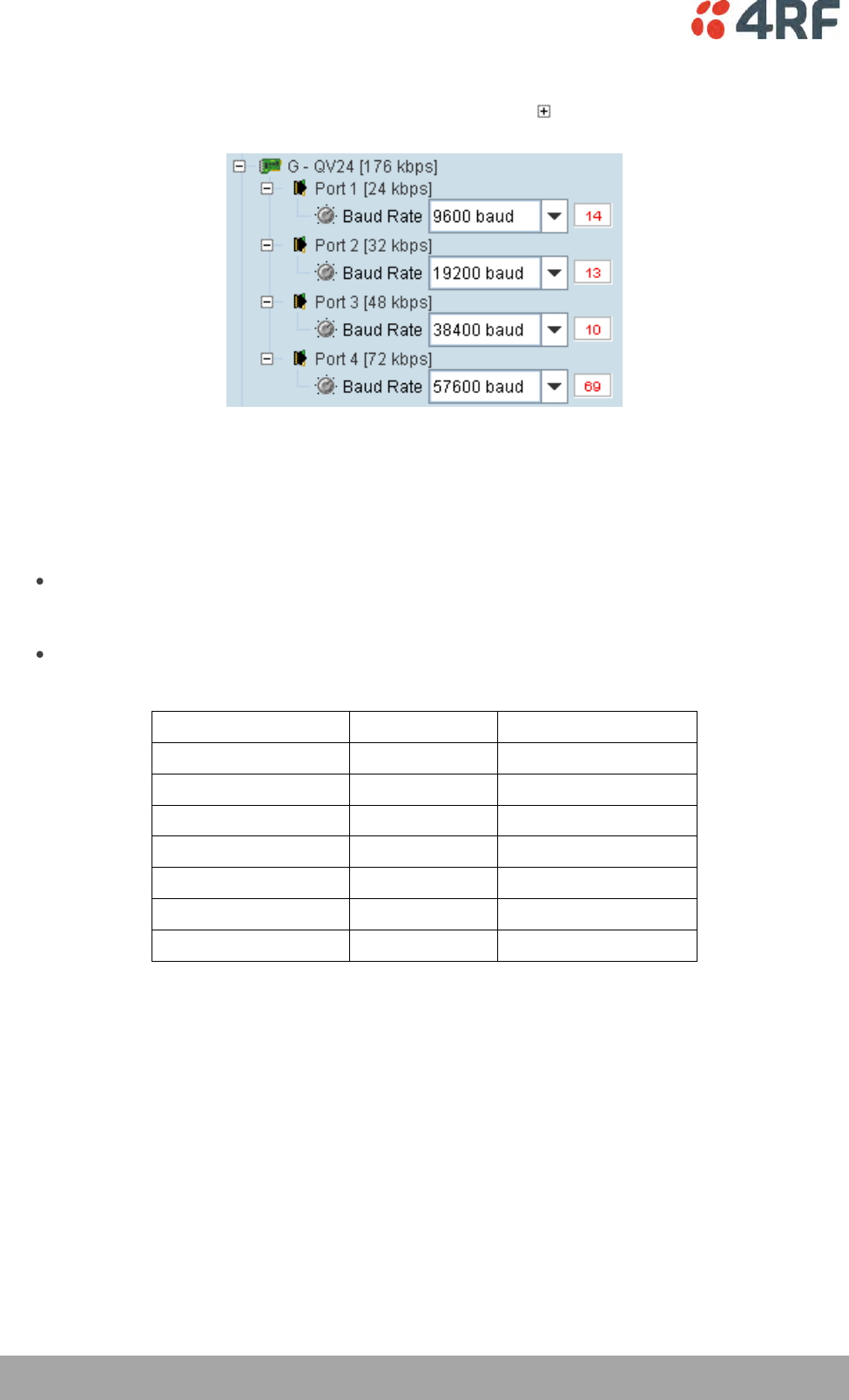
172 | Cross Connections
Aprisa XE User Manual
QV24 Cross Connections
1. Expand the QV24 displays, as required, by clicking the relevant icons.
2. Select the Port Baud Rate as required (default is 9600).
3. Drag and drop to the required partner interface to create the V.24 Data connection.
If the partner interface is a QJET:
If the V.24 Baud Rate selected is 38400 is less, drag from the QV24 mapping connection box to the
QJET timeslot. The correct QJET capacity for the baud rate selected will automatically be
assigned.
If the V.24 Baud Rate selected is greater than 38400, select the QJET capacity required, as per the
following table, and drag from the QJET to the QV24 mapping connection box.
Baud Rate
Bits Required
Bit Rate
300 - 7200
2
16 kbit/s
9600 - 14400
3
24 kbit/s
19200 - 23040
4
32 kbit/s
28800
5
40 kbit/s
38400
6
48 kbit/s
57600
9
72 kbit/s
115200
16
128 kbit/s
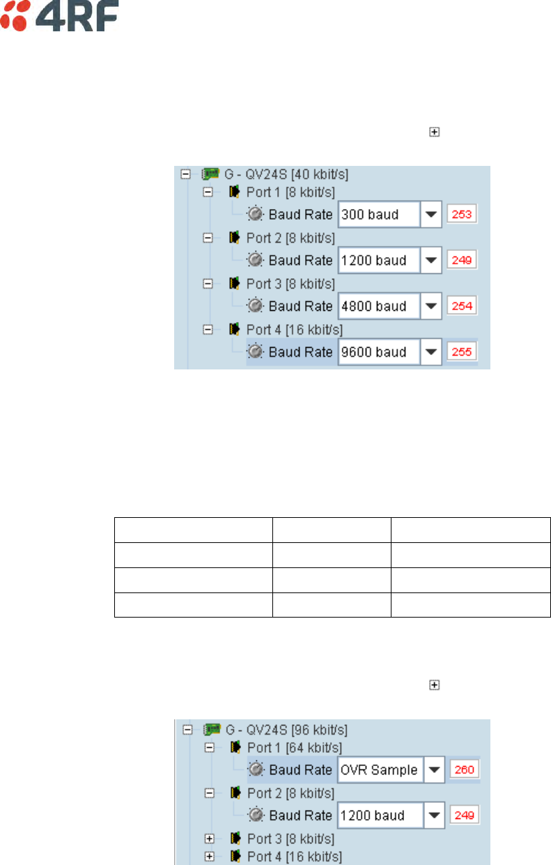
Cross Connections | 173
QV24S Cross Connections
Synchronous Mode
1. Expand the QV24S displays, as required, by clicking the relevant icons.
2. Select the Port Baud Rate as required (default is 9600).
3. Drag and drop to the required partner interface to create the V.24 Data connection.
If the partner interface is a QJET, drag from the QV24S mapping connection box to the QJET timeslot.
The correct QJET capacity for the baud rate selected will automatically be assigned.
Baud Rate
Bits Required
Bit Rate
300 - 4800
1
8 kbit/s
9600
2
16 kbit/s
19200
4
32 kbit/s
Over Sampling Mode
1. Expand the QV24S displays, as required, by clicking the relevant icons.
2. Set the Port Baud Rate to OVR Sample.
3. Drag and drop to the required E1 / T1 partner interface to create the data connection.
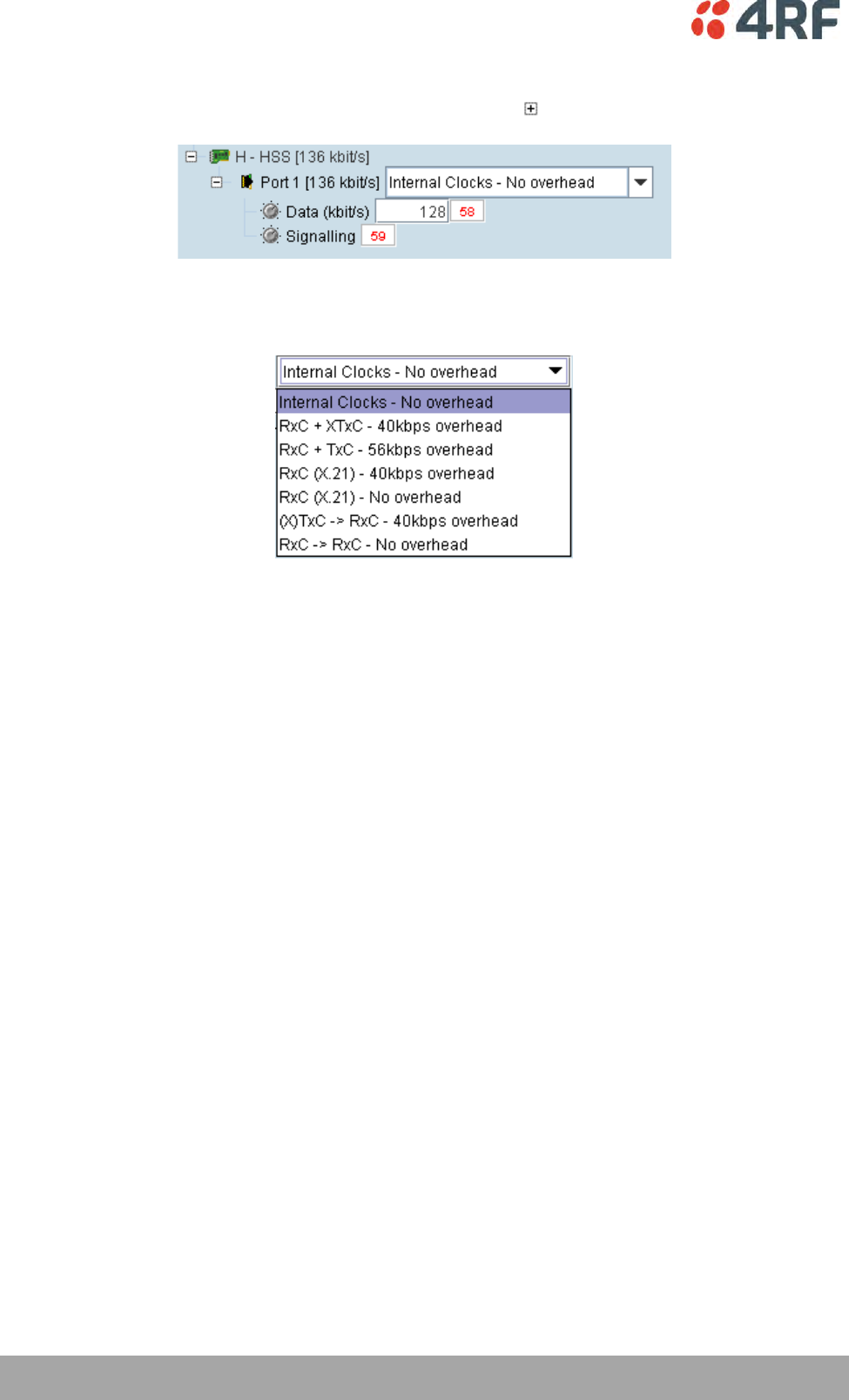
174 | Cross Connections
Aprisa XE User Manual
HSS Cross Connections
1. Expand the HSS displays, as required, by clicking the relevant icons.
2. Select the Synchronous Clock Selection mode (see ‘HSS Synchronous Clock Selection Modes’ on
page 138).
3. Set the Data rate to a value between 8 and 2048 (in multiples of 8 kbit/s).
The net data rate available to the user is defined by Data Rate – overhead
e.g. a date rate set to 2048 kbit/s with an overhead of 40 kbit/s provides a user data rate of
2008 kbit/s.
4. Drag and drop to the required partner interface to create the HSS Data connection.
If the partner interface is a QJET, select the capacity on the QJET and drag it to the HSS Data
mapping connection box.
The QJET capacity selected must be the sum of the data rate required plus the overhead rate
selected.
5. Drag and drop to the required partner interface to create the HSS Signalling cross connection. A
minimum of 8 kbit/s of capacity is required and must be set symmetrically at both ends of the link.
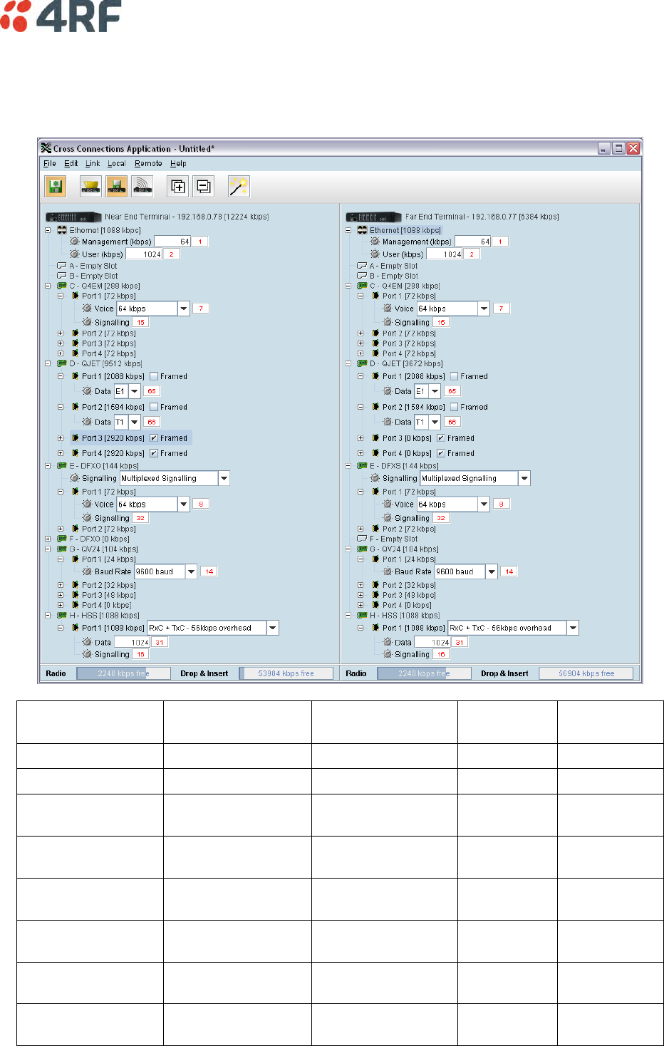
Cross Connections | 175
Cross Connection Example
This is an example of cross connection mapping:
Circuit
Local port
Remote port
Capacity
(kbit/s)
Connection
numbers
Radio management
64
1
User Ethernet
1024
2
4 wire E&M circuit
Q4EM port 1
(slot C)
Q4EM port 1
(slot C)
72
7/15
Unframed E1 data
QJET port 1
(slot D)
QJET port 1
(slot D)
2088
65
Unframed T1 data
QJET port 2
(slot D)
QJET port 2
(slot D)
1584
66
2 wire loop
Interface
DFXO port 1
(slot E)
DFXS port 1
(slot E)
72
8/32
V.24 data circuit
9600
QV24 port 1
(slot G)
QV24 port 1
(slot G)
24
14
HSS data circuit
1024 kbit/s
HSS port 1
(slot H)
HSS port 1
(slot H)
1088
31/16
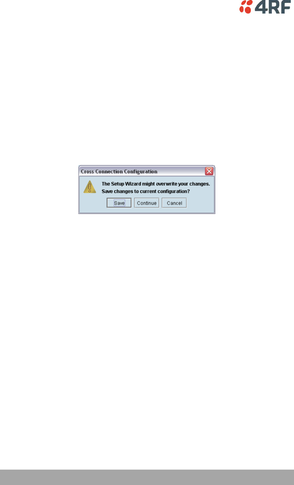
176 | Cross Connections
Aprisa XE User Manual
Symmetrical Connection Wizard
The Cross Connections application has a Symmetrical Connection Wizard which simplifies the cross
connection configuration when the terminals are fitted with symmetrical / matching interface types.
A symmetrical connection is a connection between the local and the remote terminal where the local slot,
card type, port and connection details are identical to those of the remote terminal.
The only exception is DFXO / DFXS connections where DFXO cards are considered to match DFXS cards (as
they normally interwork).
Framed E1 / T1 CAS connections, drop-and-insert connections, and connections that do not involve entire
timeslots, are considered to be asymmetrical.
Starting the Cross Connections Wizard
When starting the connection wizard with unsaved changes, the following popup dialog should appear
Click on 'Save' if you wish to save the current configuration to a file. Clicking on 'Continue' will continue
with the wizard and overwrite any changes made when the wizard finishes.
The wizard can be cancelled at any time by clicking on the 'Cancel' button or by closing the window.
Cross Connections Wizard Navigation
Click on the Next button to progress through the connection wizard. The current stage is indicated in the
navigation bar on the left. You can jump directly to a stage by clicking on the stage required.
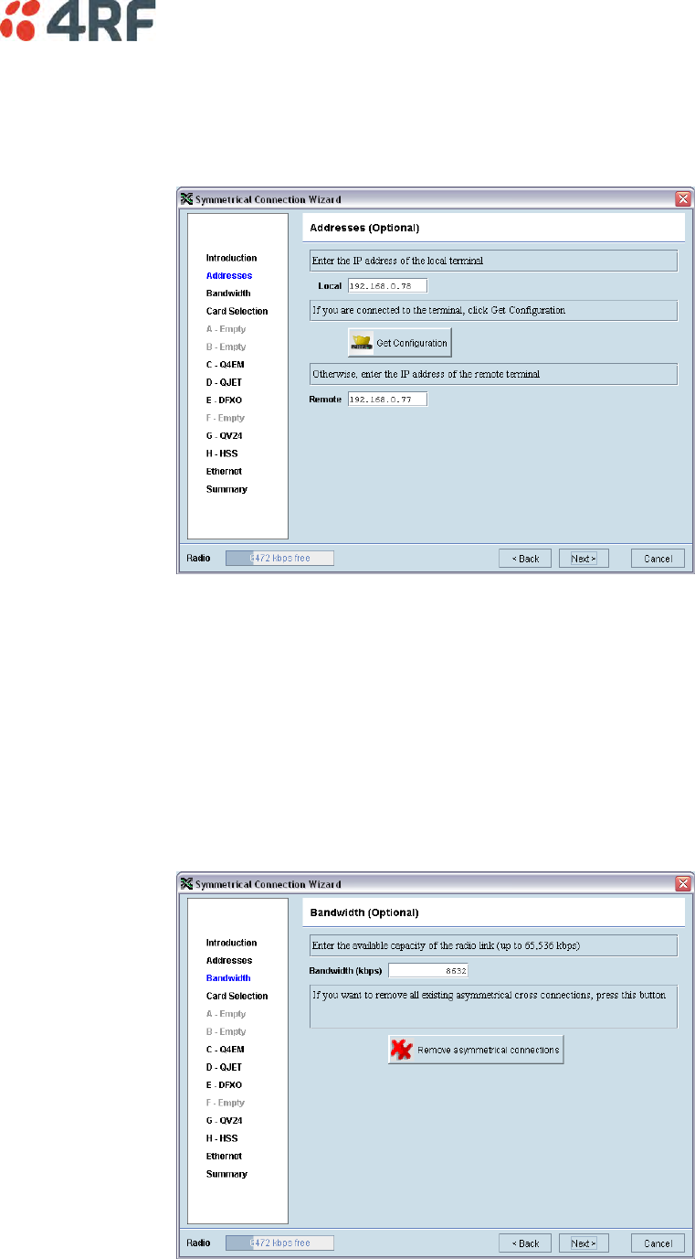
Cross Connections | 177
Setting the Cross Connections IP Address
If the local or remote terminal IP addresses have been setup, they will be displayed in the Local and
Remote fields. If the IP addresses are not displayed, enter the IP addresses of the local and remote
terminals.
Click on 'Get Configuration' to upload the existing cross connections configuration from the local terminal.
The Radio bandwidth bar will show the available bandwidth and will be updated as bandwidth is assigned
to cards.
Setting the Cross Connections Bandwidth
If the Cross Connections Application is opened from SuperVisor, the Total Capacity of the radio link will be
shown in the Bandwidth field.
If the Cross Connections Application is opened as a stand alone application, the Total Capacity of the radio
link will be need to be entered in the Bandwidth field.
The 'Remove asymmetrical connections' button will be active if there are existing asymmetrical cross
connections. If you want to remove existing asymmetrical cross connections, click on this button. The
Radio bandwidth bar will update accordingly.
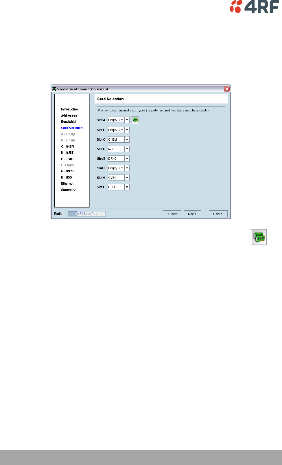
178 | Cross Connections
Aprisa XE User Manual
Cross Connections Card Selection
If the Cross Connections Application is opened from SuperVisor, existing cards installed in the local
terminal that match cards installed in the remote terminal will be displayed. Mismatched cards will be
shown as 'Empty Slot'.
If the Cross Connections Application is opened as a stand alone application, select the card types that will
be fitted in the terminal.
To copy the card type selected in Slot A to all the other slots (B – H), click on the Copy
Card button. This assumes that the same interface card types are fitted in all the card
slots.
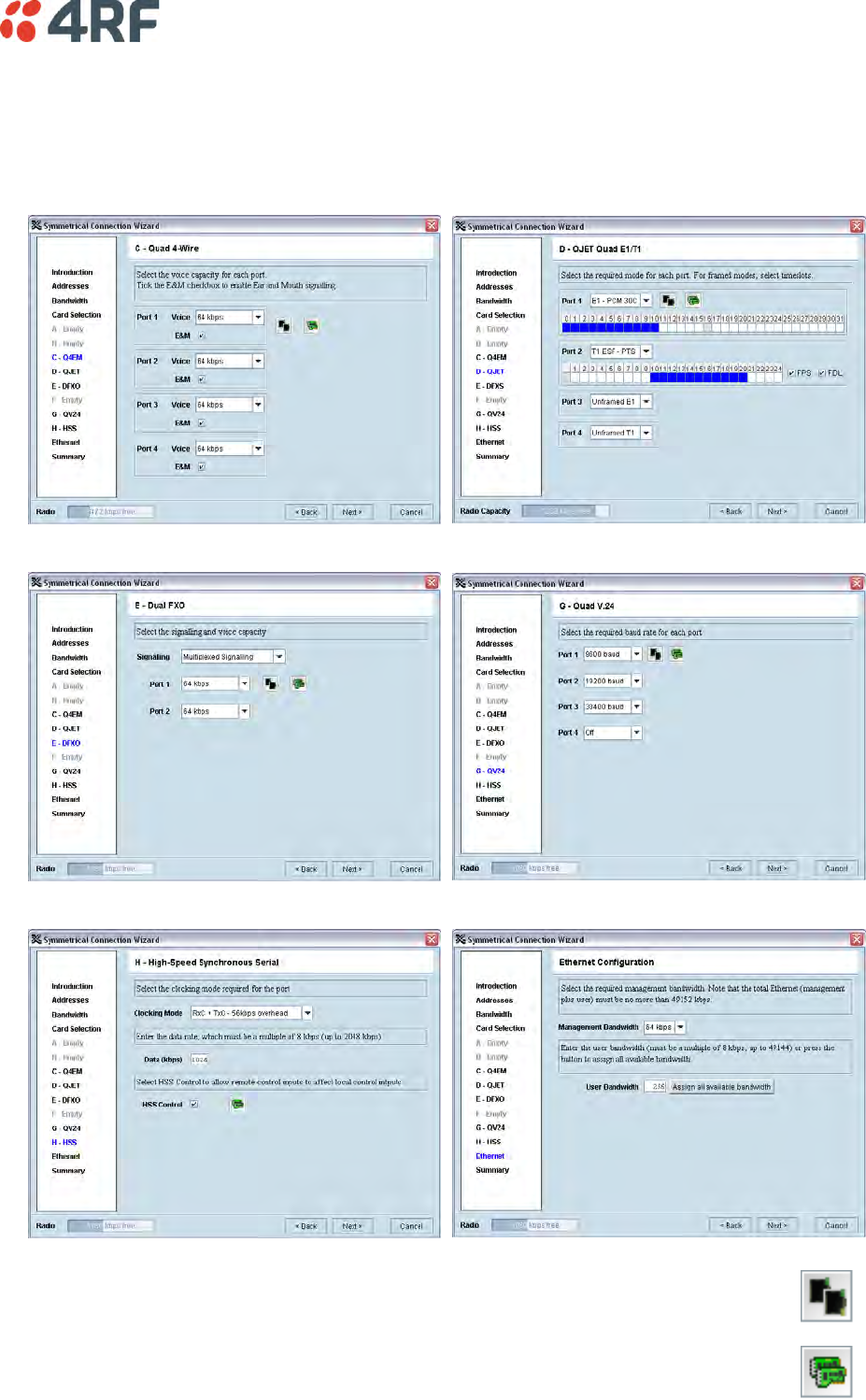
Cross Connections | 179
Cross Connections Interface Configurations
Setup the interface configurations as per the wizard instructions. Existing asymmetrical connections will
be replaced with symmetrical connections if an interface parameter is changed.
Q4EM
QJET
DFXO / DFXS
QV24
HSS
Ethernet
To copy the port configuration selected in Port 1 to all the other ports on the card,
click on the Copy Port button.
To copy the card configuration to all other cards of the same type fitted in the
terminal, click on the Copy Card button. This can save time when setting up multiple
cards of the same type.
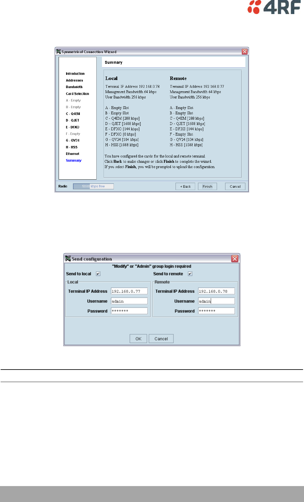
180 | Cross Connections
Aprisa XE User Manual
Symmetrical Connection Summary
Click Finish.
Send Symmetrical Connection Configuration
Click OK to send the configuration to the terminals.
The process is completed.
Note: The wizard may change the connection numbers of existing connections.
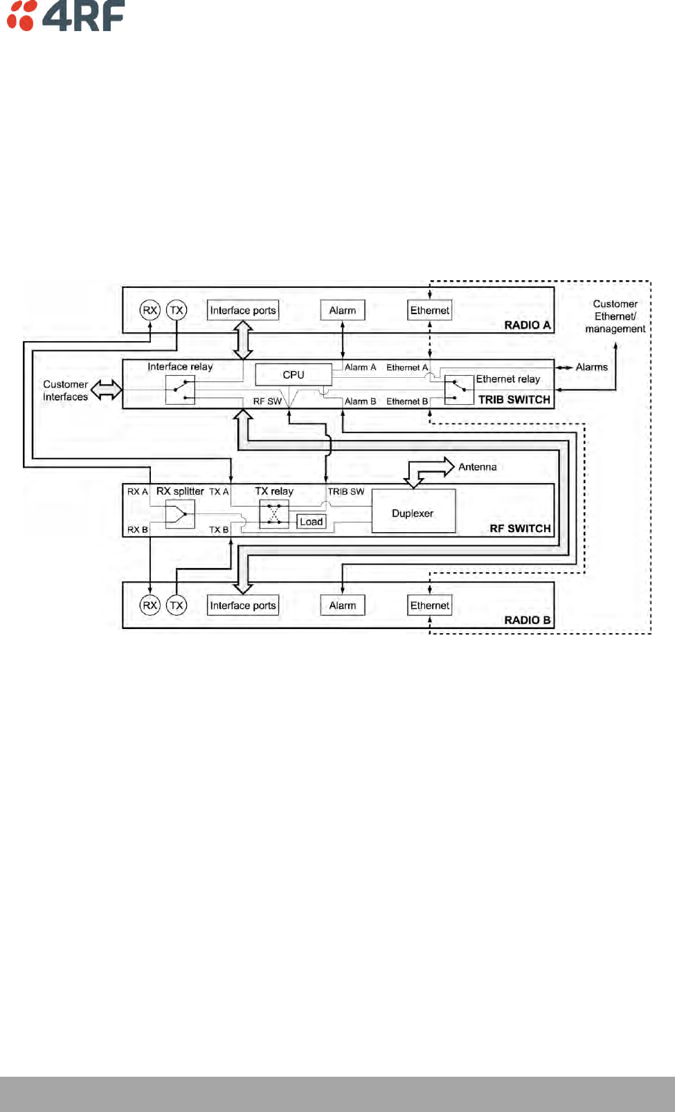
Protected Terminals | 181
Aprisa XE User Manual
11. Protected Terminals
Monitored Hot Stand By (MHSB)
This section describes configuring the protected terminal in MHSB mode.
A protected terminal in MHSB mode comprises two radios interconnected using a MHSB switch. This MHSB
switch comprises one RF switch and up to four tributary switches depending on the number of tributaries
requiring switching:
The MHSB switch protect terminals against any single failure in one radio. It also monitors the alarm
output of each radio and switches between radios if major radio link alarms occur. The MHSB switch will
not allow a switch to a faulty radio.
The MHSB switch uses a CPU to monitor the alarm status received from both the connected radios' alarm
ports. When a relevant major radio link alarm is detected on the active radio (that is, transmitter,
receiver, power supply or modem), the CPU switches a bank of relays that switches all the interfaces and
the transmit port from the main radio to a functioning stand-by radio. The stand-by radio now becomes
the active radio.
The MHSB switch has a hysteresis of 30 seconds to prevent switching on short alarm transients.
The tributary switch and the RF switch are both a 19-inch rack-mount 1U high chassis. The MHSB switch
option is available for all Aprisa XE frequency bands.
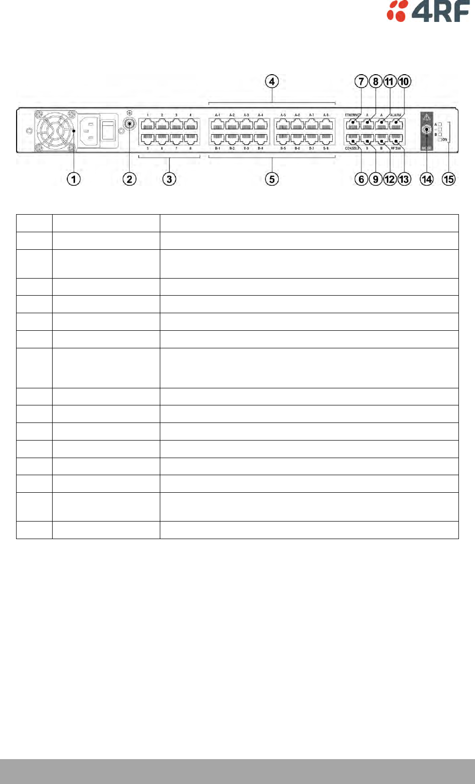
182 | Protected Terminals
Aprisa XE User Manual
Tributary Switch Front Panel
No.
Description
Explanation
1
Power supply input
Input for DC power or AC power
2
Protective earth
M5 terminal intended for connection to an external protective
conductor for protection against electric shock in case of a fault
3
Interface ports
Port for connecting to customer interface equipment
4
Radio A interfaces
These connect to the interface ports on radio A
5
Radio B interfaces
These connect to the interface ports on radio B
6
Console
For factory use only
7
Ethernet
Port for connecting to customer Ethernet network. This port is
also used to set up and manage the radios remotely over an IP
network
8
Radio A Ethernet
Connects to an Ethernet port on radio A
9
Radio B Ethernet
Connects to an Ethernet port on radio B
10
Alarms
Alarm input/output connections for customer equipment
11
Radio A alarms
Connects to the alarm port on radio A
12
Radio B alarms
Connects to the alarm port on radio B
13
RF SW
Provides power and signalling to the RF switch
14
Mode switch
Three-position locking toggle switch to set the MHSB switch into
automatic mode or radio A / radio B test mode
15
LEDs
Mode and status LEDs
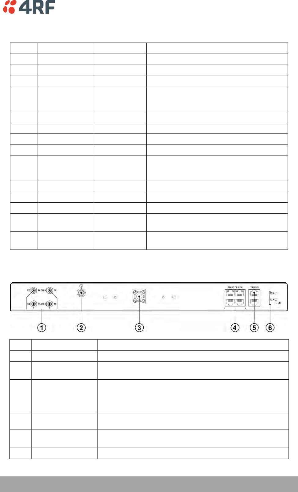
Protected Terminals | 183
Aprisa XE User Manual
Tributary Protection Switch LEDs
LED
Colour
Appearance
Explanation
A
Green
Solid
The radio is active and is OK
Green
Flashing
The radio is in standby mode and is OK
Red
Solid
The radio is active and there is a fault
No colour (off)
-
The tributary switch is in 'slave' mode and the
switching is controlled by the master tributary
switch
Red
Flashing
The radio is in standby mode, and there is a fault
B
Green
Solid
The radio is active and is OK
Green
Flashing
The radio is in standby mode and is OK
Red
Solid
The radio is active and there is a fault
No colour (off)
-
The tributary switch is in 'slave' mode and the
switching is controlled by the master tributary
switch
Red
Flashing
The radio is in standby mode, and there is a fault
~
Green
Solid
The tributary protection switch is in 'auto' mode
Green
Flashing
The tributary protection switch is in 'slave' mode
Red
Solid
The tributary protection switch is in 'manual'
mode (A or B)
On
Blue
Solid
Indicates that there is power to the tributary
protection switch
RF Switch Front Panel
No.
Description
Explanation
1
Radio QMA
QMA connectors for connecting the protected radios
2
Protective earth
M5 terminal intended for connection to an external protective
conductor for protection against electric shock in case of a fault
3
Antenna port
N-type female connector for connection to the antenna feeder
cable. This view shows an internally mounted duplexer. If an
external duplexer is fitted, the antenna port will be on the
external duplexer
4
Slave tributary
switch outputs
Connects to secondary tributary switch for control of additional
interfaces
5
Tributary switch
Connects the RF switch to the tributary switch (the master if
more than one tributary switch is required)
6
LEDs
Status LEDs
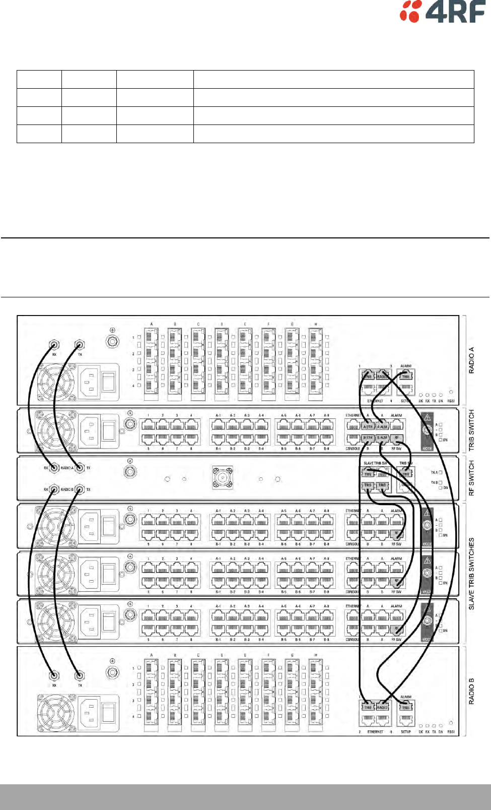
184 | Protected Terminals
Aprisa XE User Manual
RF Protection Switch LEDs
LED
Colour
Appearance
Explanation
Tx A
Green
Solid
RF is being received from radio A
Tx B
Green
Solid
RF is being received from radio B
On
Blue
Solid
Indicates that there is power to the RF protection switch
Slave Tributary Switches
Each tributary switch protects up to eight ports. Up to three slave tributary switches may be added to a
MHSB terminal to protect up to 32 ports. Each slave tributary switch is interconnected by means of the
slave tributary switch ports on the RF switch, as shown below.
Note: A tributary switch that is operating as a slave (rather than a master) has a RJ-45 V.24 loopback
connector plugged into the console port. If the connector is missing, contact Customer Support.
Alternatively, you can make this connector. Follow the standard pinouts for a V.24 RJ-45 connection (see
‘QV24 Interface connections’ on page 273).
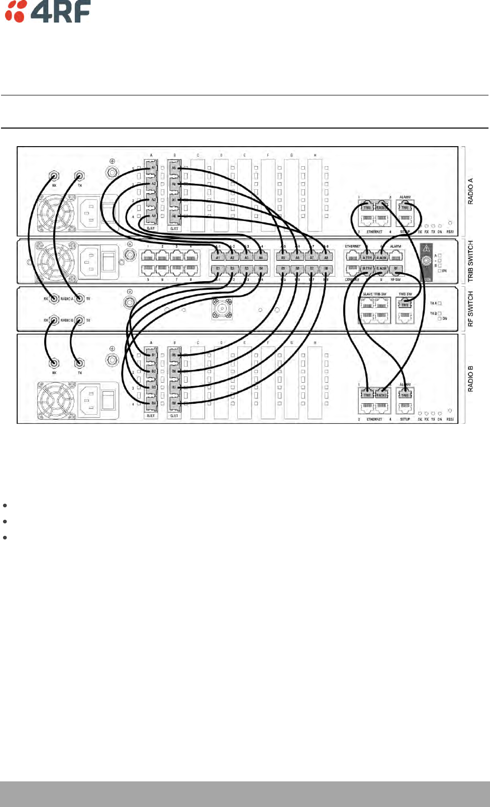
Protected Terminals | 185
Aprisa XE User Manual
MHSB Cabling
The two radios are interconnected as follows:
CAUTION: Do not connect Transmit to Receive or Receive to Transmit as this may damage the radio or the
MHSB switch.
Cables supplied with MHSB
The following cables are supplied with a MHSB terminal:
Ethernet interface: RJ-45 ports standard TIA-568A patch cables .
Alarm interface: RJ-45 ports standard TIA-568A patch cables.
RF ports: two QMA male patch cables are supplied.
MHSB Power Supply
See ‘DC Power Supply’ on page 37 and ‘AC Power Supply’ on page 40.
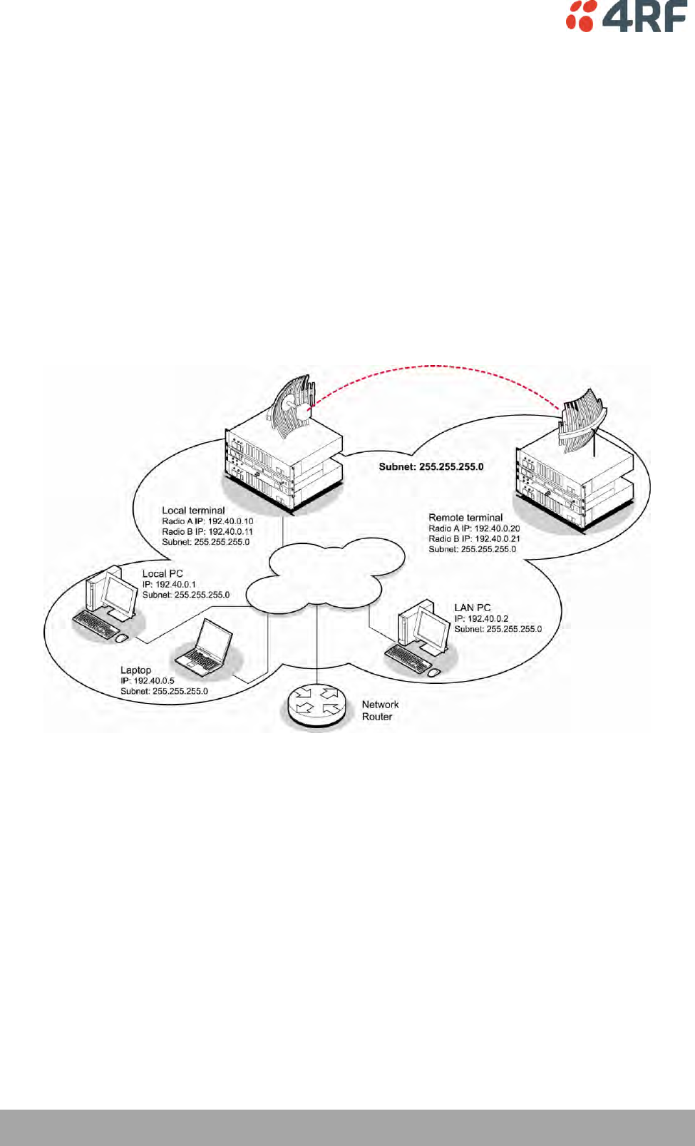
186 | Protected Terminals
Aprisa XE User Manual
Configuring the Radios for Protected Mode
The MHSB switch does not require any special software. However, the radios connected to the MHSB
switch must be configured to work with the MHSB switch. This sets the alarm outputs and inputs to
function in MHSB mode.
You must configure the interfaces of both radios connected to the MHSB switch identically. To perform
this, you can either connect directly to the radio or use the test mode of the MHSB switch.
MHSB Terminal IP Addresses
Before configuring the link, you must ensure that the two independent links have correctly configured IP
address details.
All four radios in the protected link must be on the same subnet.
Example of MHSB IP addressing
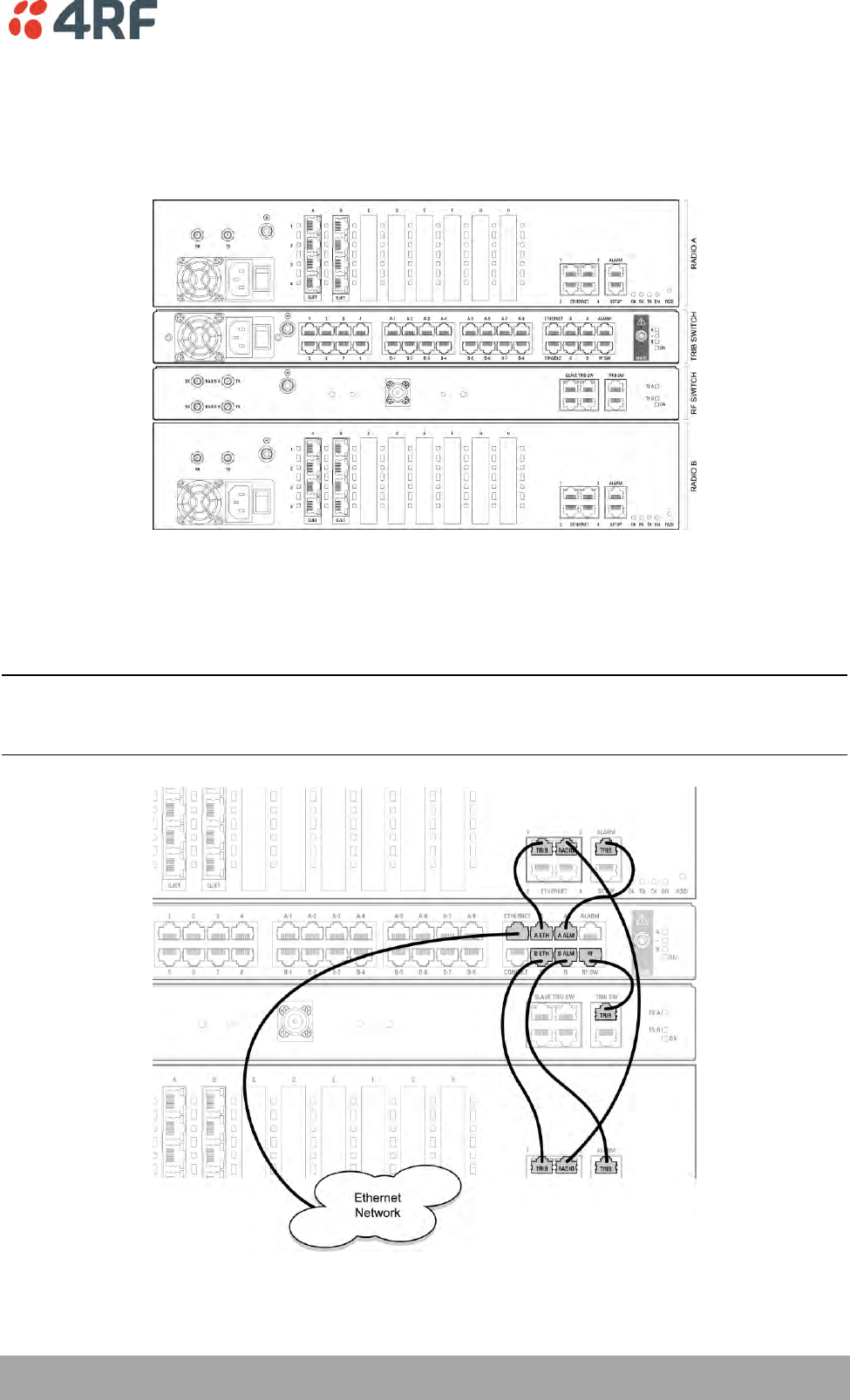
Protected Terminals | 187
Aprisa XE User Manual
Mounting the MHSB Radios and Switches
Once the IP addresses are correctly configured, it is important to connect the A and B radios' Ethernet and
Alarm ports correctly. In general, mount radio A above the MHSB switch and radio B below the MHSB
switch:
There is an Ethernet connection between any of the four Ethernet ports on each radio and the Ethernet
port on the Tributary switch. There is also a connection between radio A and radio B, which ensures
Ethernet traffic is maintained if a radio loses power.
The Ethernet port on the protection switch can be connected to an Ethernet hub or switch to allow
multiple connections.
Important: The management Ethernet capacity on each of the four radios in the protected terminal must
be identical for remote communications to work and there should only be one IP connection to the
management network (via the tributary switch Ethernet port).
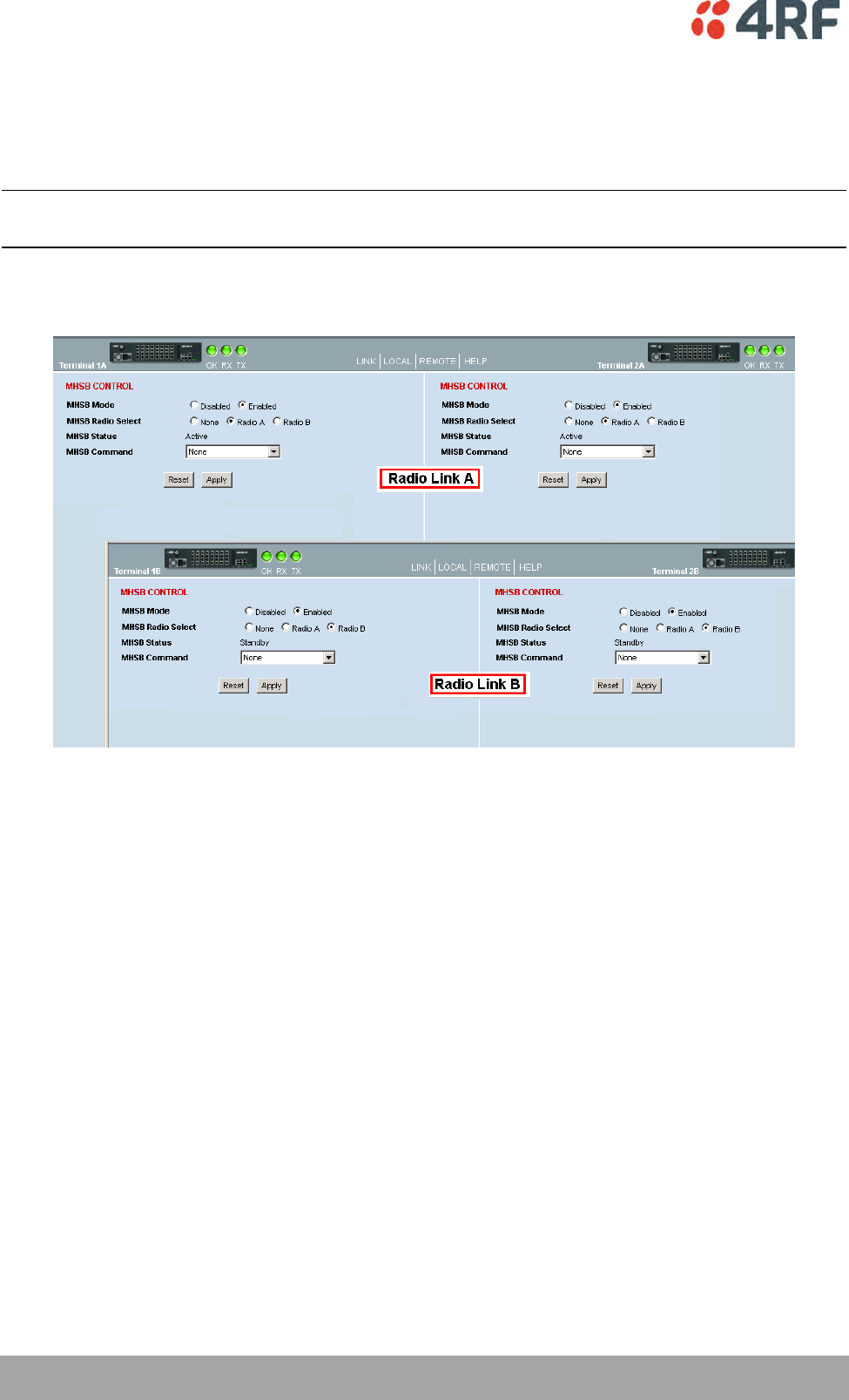
188 | Protected Terminals
Aprisa XE User Manual
Configuring the Terminals for MHSB
It is recommended that you configure the local and remote A side first, then the local and remote B side.
Both the local A and B radios must be configured identically, and both the remote A and B radios must be
configured identically.
Tip: As illustrated below, you may find it helpful to have two browser sessions running simultaneously.
You can then easily see both the A and B sides of the protected link.
To configure MHSB operation:
1. Select Link > Maintenance > MHSB.
2. Enable MHSB mode.
3. Select whether the radio is A or B.
Ensure that the radio connected to the A side of the protection switch (normally above the MHSB
switch) is set to Radio A and the radio connected to the B side of the protection switch (normally
below the MHSB switch) is set to Radio B.
In the event of a power outage, the radios will switch over to the A side of the protection switch when
the power is restored. The A side is also the default active side.
4. When you have made your changes, click Apply to apply changes or Reset to restore the previous
configuration.
5. Repeat steps 2 to 4 for the other side of the protected link.
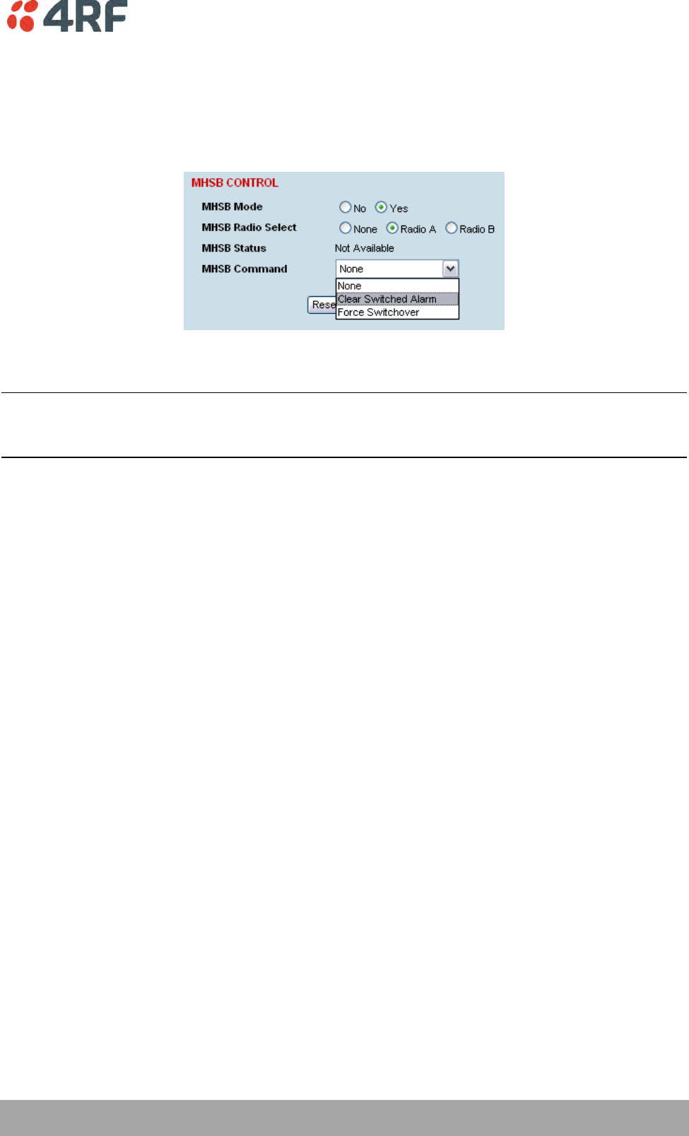
Protected Terminals | 189
Aprisa XE User Manual
Clearing MHSB Alarms
If a switchover event occurs, the OK LED on the front panel and on the Terminal status and menu bar in
SuperVisor changes to amber.
1. Select Clear Switched Alarm from the MHSB Command drop-down list.
2. Click Apply to apply changes or Reset to reset the page.
Note: When MHSB mode is enabled, external alarm input 2 is used by the protection system to carry
alarms from the protection switch to the radio. In MHSB mode, therefore, only external alarm input 1 is
available for user alarms.
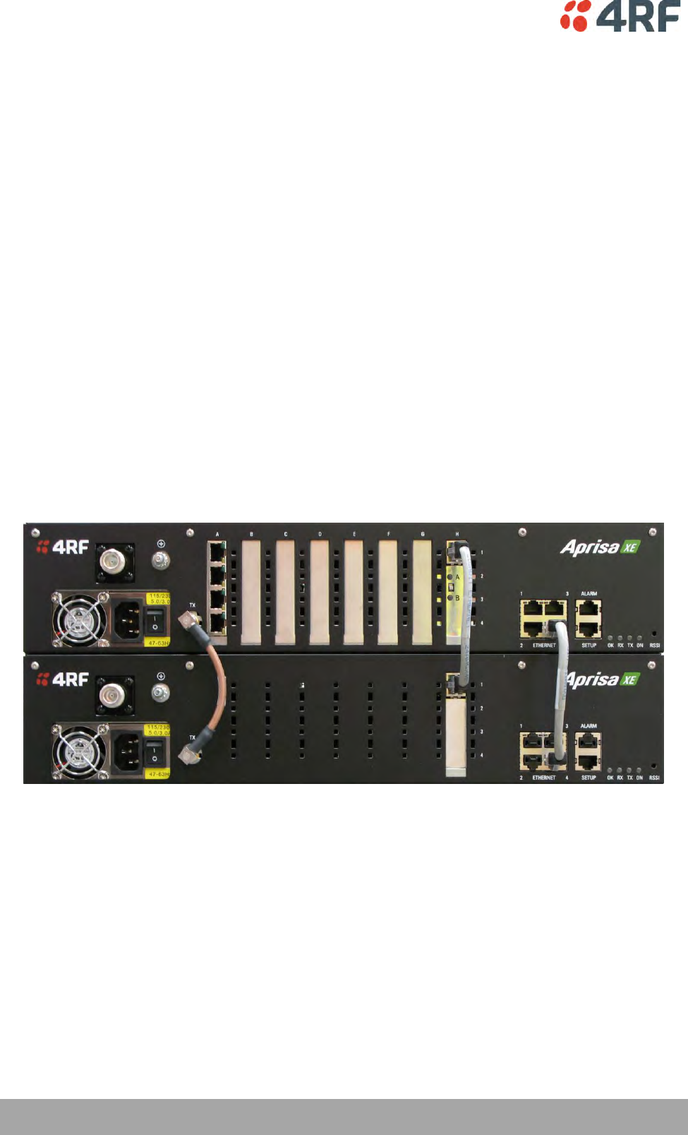
190 | Protected Terminals
Aprisa XE User Manual
Hitless Space Diversity (HSD)
HSD provides hitless RF receive path protection and hot standby transmitter redundancy. It is typically
deployed for paths where high path availability is required.
An Aprisa XE hitless space diversity terminal comprises two radio terminals, radio A and radio B.
Radio A is the primary radio which is fitted with the interface cards and connects to antenna A.
Antenna A always carries the transmitted signal and the received signal for Radio A.
Radio B is the secondary radio the receiver of which connects to antenna B. The transmitter in this radio is
the standby transmitter.
In the event of a radio A active transmitter failure, radio B transmitter becomes active.
Antenna B only carries the received signal for Radio B. This antenna is physically separated on the tower
by a pre-determined distance from Antenna A.
As both radios have a receive path, traffic from the path with the best received bit error rate is routed to
the customer interfaces in radio A.
In an HSD terminal, a HSD Protection Switch Card (PSC) is always fitted in slot H in Radio A and a HSD
Protection Interface Card (PIC) is always fitted in slot H in Radio B. The PSC card has a card front switch
which controls the hardware setting of the HSD system Active Radio (Auto Select, Radio A or Radio B).
Customer interfaces are provided on radio A only in interface slots A to G. Interface connections to
Ethernet and the external alarm inputs and outputs are also provided on radio A only.
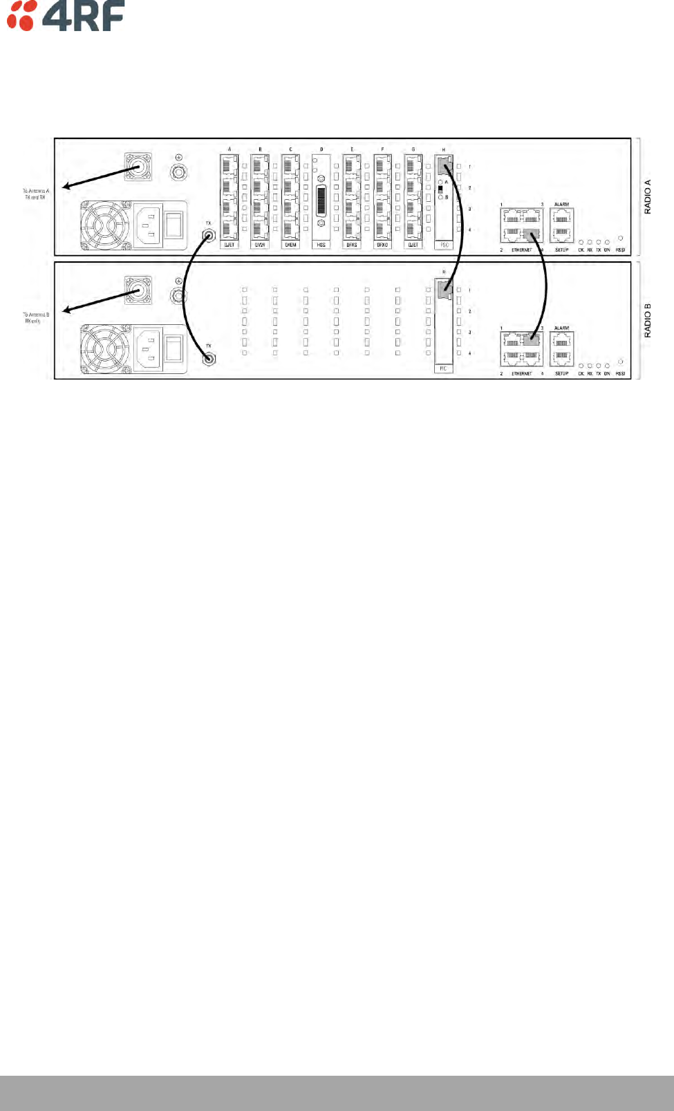
Protected Terminals | 191
Aprisa XE User Manual
HSD Terminal Cabling
The two HSD radios are interconnected as follows:
Cables Supplied with HSD Terminal
The following cables are supplied with a HSD terminal:
RF cable
A 110 mm QMA female to QMA female low loss RF cable is required to interconnect between the TX ports
of both radio A and radio B. This cable carries the radio B transmitter output to the radio A transmitter
switch.
Ethernet Cable
A 200 mm RJ45 to RJ45 Ethernet cable between the Ethernet ports of radio A and radio B. This cable
carries management IP traffic between radio A and radio B.
Traffic Cable
A 200 mm RJ45 to RJ45 Ethernet cable between the PSC and PIC. This cable carries all user traffic
between Radio A and Radio B.
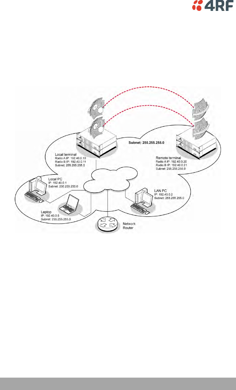
192 | Protected Terminals
Aprisa XE User Manual
HSD Terminal IP Addresses
Each radio in the HSD link is assigned a unique IP address. All four radios in the HSD link must be on the
same subnet.
The IP address of the four terminals can only be changed by logging into the relevant radio A or radio B.
When the IP addresses have been setup, an ethernet connection to any of the four radios can access all
four radios in the HSD link. The usual ethernet connection is to the near end Radio A (see ‘IP Addressing of
Terminals’ on page 53).
Example of IP addressing
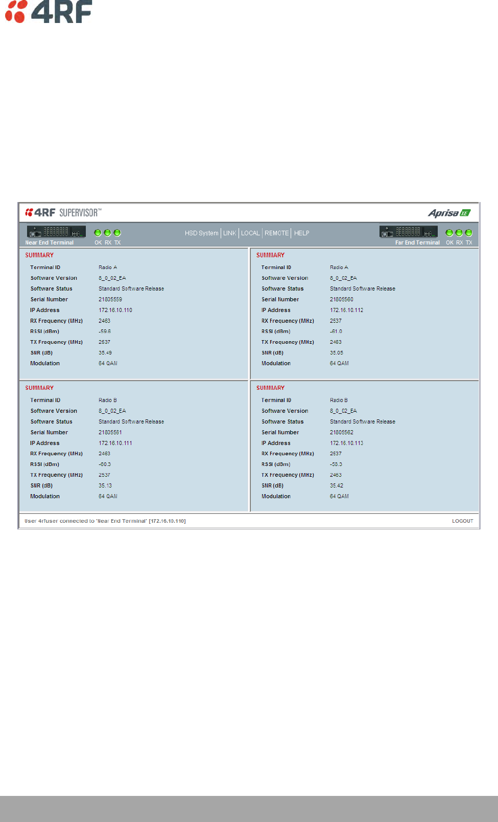
Protected Terminals | 193
Aprisa XE User Manual
Configuring HSD Terminals
To simplify the management and configuration of the HSD terminals, SuperVisor provides four windows
which display the parameters for all four radios, the local and remote, radios A and B. The HSD System
menu item displays the four windows.
When a parameter is changed in the four window mode, the relevant parameter is automatically changed
to the same setting on the corresponding radio e.g. if a radio A modulation type is changed, the radio B
modulation type is also changed to the same setting.
The Local and Remote menus continue to display the parameters for the local and remote radios for the
near end terminal logged into.
The majority of SuperVisor HSD System pages contain the same parameters and controls as the standard
1+0 XE terminal. The main exceptions are the HSD Control page and the HSD Performance Summary page.
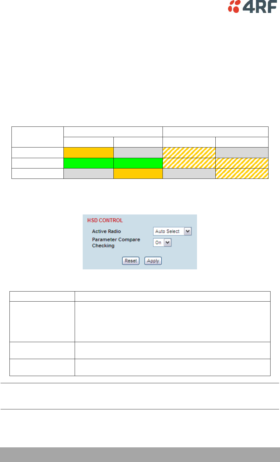
194 | Protected Terminals
Aprisa XE User Manual
HSD Active Radio Control
The HSD system ‘Active Radio’ control determines if the selection of Radio A or Radio B is automatic or
manual. This controls both the radio transmitters and receivers.
The Active Radio can be set with the hardware switch on the PSC card front or with the SuperVisor
software control. The last change of hardware / software control determines the state of the HSD system.
The SuperVisor software control will always reflect the state of the HSD system.
After terminal startup or reboot, the state of the PSC mode switch determines the setting used by the
system and the SuperVisor software control is set to reflect the state of the HSD system.
The PSC card has two card front LEDs which indicate the status of the HSD system:
PSC Mode
Switch
Hardware Control Change
Software Control Change
LED A
LED B
LED A
LED B
Radio A
Solid Amber
Off
Flashing Amber
Off
Auto Select
Solid Green
Solid Green
Flashing Amber
Flashing Amber
Radio B
Off
Solid Amber
Off
Flashing Amber
To set the HSD controls:
1. Select HSD System > Maintenance > Control.
2. Set the Active Radio parameter.
Active Radio
Mode of Operation
Auto Select
(default)
Automatic mode:
The hitless receive will select traffic from the receive path of best
performance
The HSD system will switch to the standby transmitter if the active
transmitter fails (TX failure alarm)
Radio A Only
Manual selection of radio path A only for both the transmitter and
receiver i.e. no automatic switching
Radio B Only
Manual selection of radio path B only for both the transmitter and
receiver i.e. no automatic switching
Note: There is no timeout for a manual selection of the Active Radio setting (Radio A only or Radio B only)
but a ‘Mode Switch Software Override’ alarm will warn if the software has overwritten the PSC Mode
Switch.
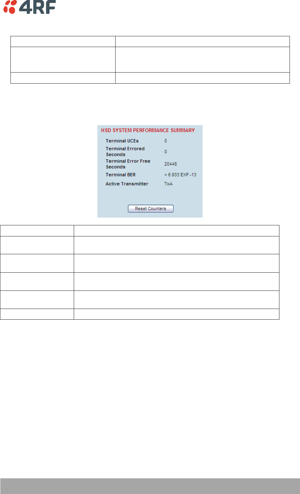
Protected Terminals | 195
Aprisa XE User Manual
3. Set the Parameter Compare Checking.
Parameter Compare Checking
Option
On
(default)
Any mismatch in parameters shown in Terminal Settings
between Radio A and Radio B will generate a Parameter
Mismatch alarm.
Off
No Parameter Mismatch alarm will be generated.
To view the HSD System Performance Summary:
1. Select HSD System > Performance > Summary.
Field
Explanation
Terminal UCEs
The total number of HSD terminal uncorrectable blocks since the last
reset
Terminal Errored
seconds
The total number of HSD terminal operational seconds with errored
traffic since the last reset
Terminal Error free
seconds
The total number of HSD terminal error free operational seconds since
the last reset
Terminal BER
The system will report an estimated HSD terminal Bit Error Rate up to a
maximum of 1 in 1021
Active Transmitter
Dislays the current active transmitter (TxA or TxB)
Click Reset Counters to reset the error counters to zero.
In-Service Commissioning | 197
Aprisa XE User Manual
12. In-Service Commissioning
Before You Start
When you have finished installing the hardware, RF and the traffic interface cabling, the system is ready
to be commissioned. Commissioning the terminal is a simple process and consists of:
1. Powering up the terminals
2. Configuring both the local and remote terminals using SuperVisor
3. Aligning the antennas
4. Synchronizing the terminals
5. Testing the link is operating correctly. As a minimum, conduct the suggested tests to ensure correct
operation. More extensive testing may be required to satisfy the end client or regulatory body
requirements.
6. Connecting up the client or user interfaces
What You Will Need
Appropriately qualified commissioning staff at both ends of the link.
Safety equipment appropriate for the antenna location at both ends of the link.
Communication equipment, that is, mobile phones or two-way radios.
SuperVisor software running on an appropriate laptop, computer, or workstation at one end of the
link.
Tools to facilitate loosening and re-tightening the antenna pan and tilt adjusters.
Predicted receiver input levels and fade margin figures from the radio link budget (You can use
Surveyor (see ‘Path planning’ on page 23) to calculate the RSSI, fade margin, and availability).
198 | In-Service Commissioning
Aprisa XE User Manual
Applying Power to the Terminals
WARNING:
Before applying power to a terminal, ensure you have connected the safety
earth and antenna cable.
Apply power to the terminals at each end of the link.
When power is first applied, all the front panel LEDs will illuminate red for several seconds as the system
initializes.
After the system is initialized, the OK LED on the front panel should illuminate green and if the terminals
are correctly configured, the TX and RX LED should also be illuminated green.
If the RX LED is:
Red
the antennas are may be significantly mis-aligned with no signal being
received
Amber
the antennas may be roughly aligned with some signal being received
Green
the antennas are well-aligned and adequate signal is being received to create
a reliable path
If the TX LED is:
Red
the transmitter is faulty
Amber
there is a fault in the antenna connection or feeder cable
Green
the transmitter is working normally
Review the Link Configurations Using SuperVisor
1. Connect a PC, with SuperVisor installed, to both terminals in the link.
2. Log into the link.
3. Select Link > Summary and confirm the following basic information:
Terminal IP address(es)
Terminal TX and RX frequencies
RSSI (dBm)
TX power (dBm)
SNR (dBm)
Note: If the terminals have not already been configured, refer to ‘Configuring the terminal’ on page 69,
‘Configuring the traffic interfaces’ on page 91, and ‘Configuring the traffic cross connections’ on page
145.
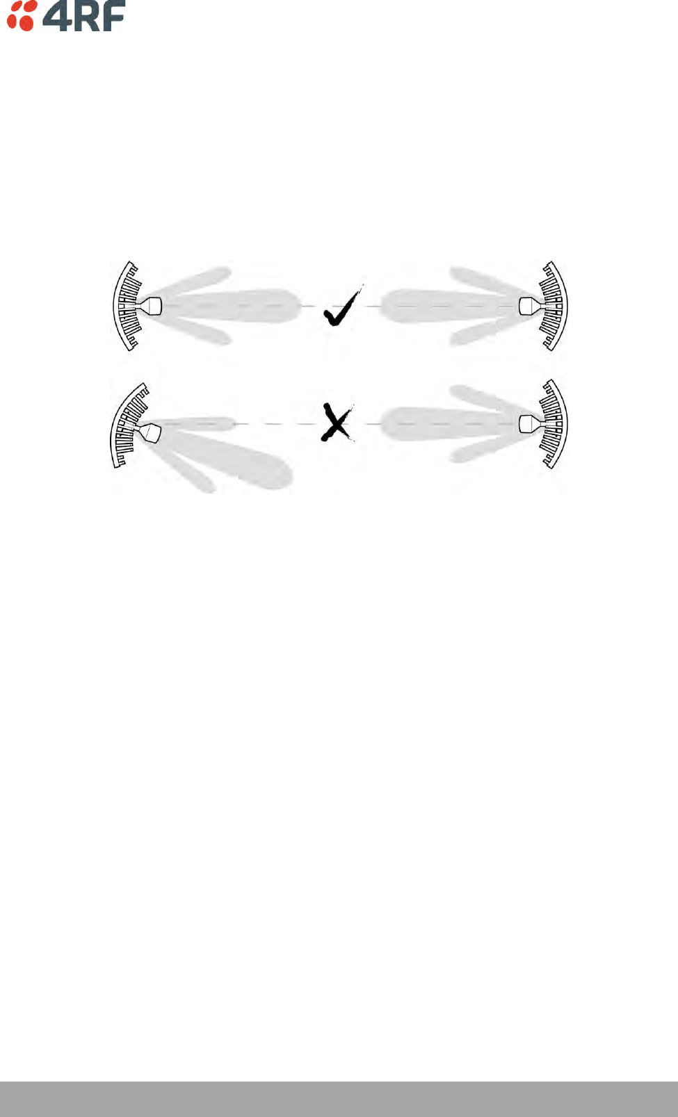
In-Service Commissioning | 199
Aprisa XE User Manual
Antenna Alignment
For any point-to-point link, it is important to correctly align the antennas to maximize the signal strength
at both ends of the link. Each antenna must be pointing directly at the corresponding antenna at the
remote site, and they must both be on the same polarization. The antennas are aligned visually, and then
small adjustments are made while the link is operating to maximize the received signal.
Directional antennas have a radiation pattern that is most sensitive in front of the antenna, in line with
the main lobe of the radiation pattern. There are several other lobes (side lobes) that are not as sensitive
as the main lobe in front of the antenna.
For the link to operate reliably, it is important that the main lobes of both antennas are aligned. If any of
the side lobes are aligned to the opposite antenna, the received signal strength of both terminals will be
lower, which could result in fading. If in doubt, check the radiation patterns of the antennas you are
using.
Checking the Antenna Polarization
Check that the polarization of the antennas at each end of the link is the same.
Antenna polarization of grid antennas are normally indicated by an arrow or with ‘H’ and ‘V’ markers
(indicating horizontal and vertical).
On Yagi antennas, ensure the orientation of the elements are the same at each end of the link.
Transmit frequency and power, and antenna polarization would normally be defined by a regulatory body,
and typically licensed to a particular user. Refer to your license details when setting the antenna
polarization.
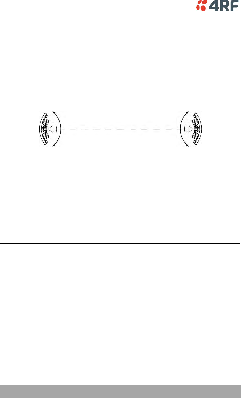
200 | In-Service Commissioning
Aprisa XE User Manual
Visually Aligning Antennas
1. Stand behind the antenna, and move it from side to side until it is pointing directly at the antenna at
the remote site. The remote antenna may be made more visible by using a mirror, strobe light, or
flag.
If the remote end of the link is not visible (due to smoke, haze, or local clutter, etc), align the
antenna by using a magnetic compass. Calculate the bearing using a scale map of the link path.
When setting the antenna on the desired bearing ensure that you use the appropriate true-north to
magnetic-north offset. Also ensure that the compass reading is not affected by standing too close to
metallic objects.
2. Once the antenna is pointing at the remote antenna, tighten the nuts on the U-bolt or antenna clamp
just enough to hold it in position. Leave the nuts loose enough so that small adjustments can still be
made. Check that the antenna is still pointing in the correct direction.
3. Move the antenna up or down until it is pointing directly at the remote site.
4. Tighten the elevation and azimuth adjustment clamps.
5. Mark the position of the antenna clamps so that the antenna can be returned to this rough aim point
easily when accurately aligning the antennas.
6. Repeat steps 1-5 at the opposite site.
Note: Low gain antennas need less adjustment in elevation as they are simply aimed at the horizon. They
should always be panned horizontally to find the peak signal.
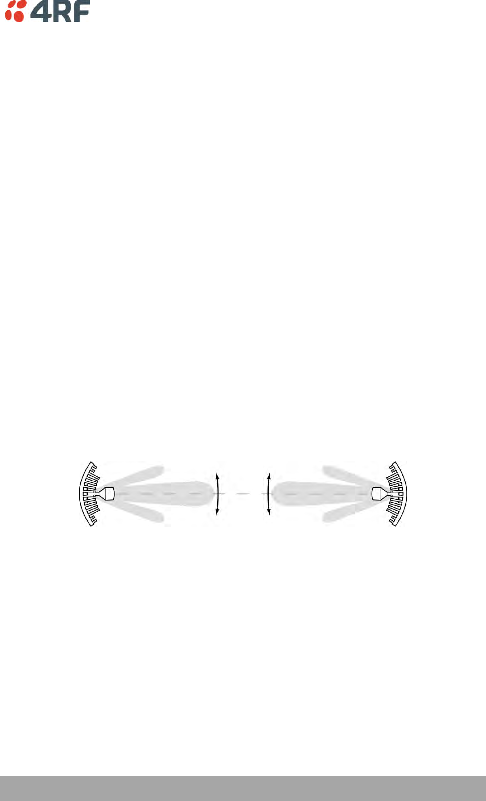
In-Service Commissioning | 201
Aprisa XE User Manual
Accurately Aligning the Antennas
Once the antennas are visually aligned, accurately align both antennas by carefully making small
adjustments while monitoring the RSSI. This will give the best possible link performance.
Note: Remember that it is important to align the main radiation lobes of the two antennas to each other,
not any side lobes. It may be easier to perform this procedure if you can communicate with someone at
the remote site by telephone, mobile, or two-way radio.
1. Connect a laptop PC running SuperVisor software and power up the terminals at both ends of the link.
Select Link > Performance > Summary so that you can see the RSSI indication for the local terminal.
Alternatively, use the RSSI test point on the front panel together with a multimeter (see ‘Measuring
the RSSI’ on page 202).
2. Move the antenna through a complete sweep horizontally (known as a 'pan') either side of the point
established in the visual alignment process above. Note down the RSSI reading for all the peaks in RSSI
that you discover in the pan.
3. Move the antenna to the position corresponding to the maximum RSSI value obtained during the pan.
Move the antenna horizontally slightly to each side of this maximum to find the two points where the
RSSI drops slightly.
4. Move the antenna halfway between these two points and tighten the clamp.
5. If the antenna has an elevation adjustment, move the antenna through a complete sweep (known as a
'tilt') vertically either side of the point established in the visual alignment process above. Note down
the RSSI reading for all the peaks in RSSI that you discover in the tilt.
6. Move the antenna to the position corresponding to the maximum RSSI value obtained during the tilt.
Move the antenna slightly up and then down from the maximum to find the two points where the RSSI
drops slightly.
7. Move the antenna halfway between these two points and tighten the clamp.
8. Recheck the pan (steps 2-4) and tighten all the clamps firmly.
9. Perform steps 1-8 at the remote site.
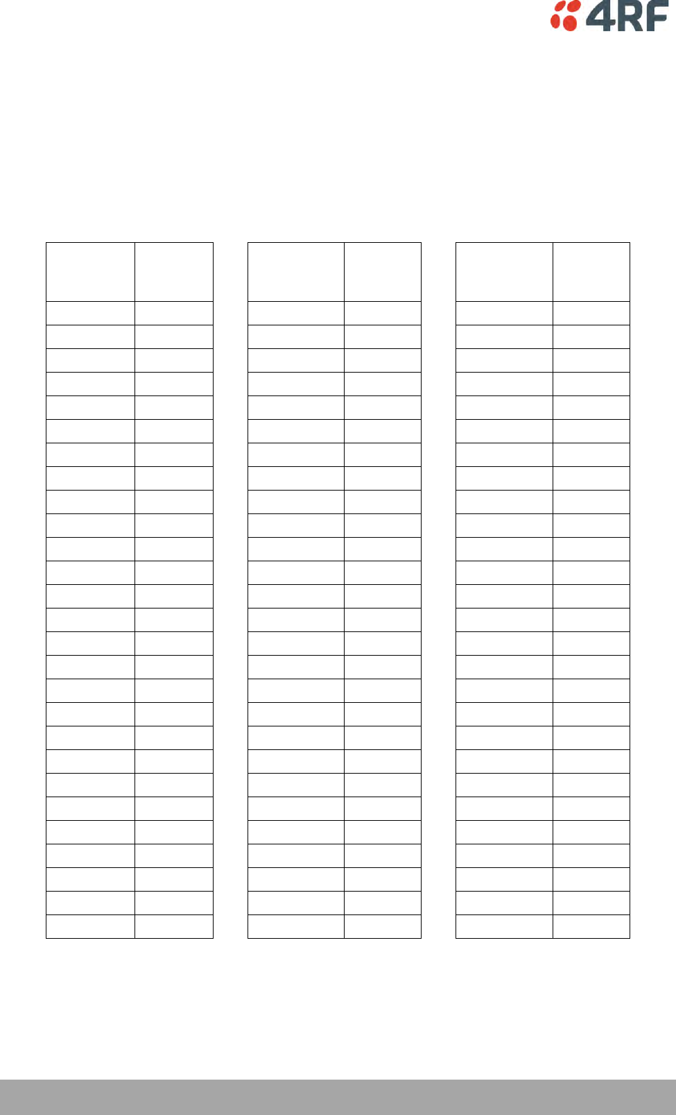
202 | In-Service Commissioning
Aprisa XE User Manual
Measuring the RSSI
Measure the RSSI value with a multimeter connected to the RSSI test port on the front of the terminal (see
‘Front panel connections and indicators’ on page 31).
1. Insert the positive probe of the multimeter into the RSSI test port, and clip the negative probe to the
chassis of the terminal (earth).
2. Pan and tilt the antenna until you get the highest VDC reading. The values shown in the table below
relate the measured VDC to the actual received signal level in dBm regardless of bandwidth and
frequency.
RSSI test
port value
(VDC)
RSSI
reading
(dBm)
RSSI test
port value
(VDC)
RSSI
reading
(dBm)
RSSI test
port value
(VDC)
RSSI
reading
(dBm)
0.000
- 100
0.675
- 73
1.350
- 46
0.025
- 99
0.700
- 72
1.375
- 45
0.050
- 98
0.725
- 71
1.400
- 44
0.075
- 97
0.750
- 70
1.425
- 43
0.100
- 96
0.775
- 69
1.450
- 42
0.125
- 95
0.800
- 68
1.475
- 41
0.150
- 94
0.825
- 67
1.500
- 40
0.175
- 93
0.850
- 66
1.525
- 39
0.200
- 92
0.875
- 65
1.550
- 38
0.225
- 91
0.900
- 64
1.575
- 37
0.250
- 90
0.925
- 63
1.600
- 36
0.275
- 89
0.950
- 62
1.625
- 35
0.300
- 88
0.975
- 61
1.650
- 34
0.325
- 87
1.000
- 60
1.675
- 33
0.350
- 86
1.025
- 59
1.700
- 32
0.375
- 85
1.050
- 58
1.725
- 31
0.400
- 84
1.075
- 57
1.750
- 30
0.425
- 83
1.100
- 56
1.775
- 29
0.450
- 82
1.125
- 55
1.800
- 28
0.475
- 81
1.150
- 54
1.825
- 27
0.500
- 80
1.175
- 53
1.850
- 26
0.525
- 79
1.200
- 52
1.875
- 25
0.550
- 78
1.225
- 51
1.900
- 24
0.575
- 77
1.250
- 50
1.925
- 23
0.600
- 76
1.275
- 49
1.950
- 22
0.625
- 75
1.300
- 48
1.975
- 21
0.650
- 74
1.325
- 47
2.000
- 20
In-Service Commissioning | 203
Aprisa XE User Manual
Checking Performance
The amount of testing performed on the completed installation will depend on circumstances. Some
customers may need to prove to a local licensing regulatory body that the link complies with the license
provisions. This may require special telecommunications test equipment to complete these tests. Most
customers simply want to confirm that their data traffic is successfully passing over the link, or that the
customer interfaces comply with known quality standard.
However, the most important performance verification checks are:
Receive input level
Fade margin
Long-term BER
Checking the Receive Input Level
The received signal strength at the local terminal is affected by many components in the system and has a
direct relationship with the resulting performance of the link. A link operating with a lower than expected
signal strength is more likely to suffer from degraded performance during fading conditions. The receive
input level of a link is normally symmetrical (that is, similar at both ends).
1. Compare the final RSSI figure obtained after antenna alignment with that calculated for the link.
2. If the RSSI figure is in excess of 3 dB down on the predicted level, recheck and correct problems using
the table below and then recheck the RSSI. Alternatively, recheck the link budget calculations.
Possible cause
Terminal(s)
Is the terminal operating on the correct frequency?
Local & remote
Is the remote terminal transmit power correct?
Remote
Are all the coaxial connectors tight?
Local & remote
Is the antenna the correct type, that is, gain and frequency of operation?
Local & remote
Is the antenna polarized?
Local & remote
Is the antenna aligned?
Local & remote
Is the path between the terminals obstructed?
Note: If following the above steps does not resolve the situation, contact Customer Support for
assistance.
3. Record the RSSI figure on the commissioning form.
4. Repeat steps 1 to 2 for the other end of the link.
204 | In-Service Commissioning
Aprisa XE User Manual
Checking the Fade Margin
The fade margin is affected by many components in the system and is closely related to the received
signal strength. A link operating with a lower than expected fade margin is more likely to suffer from
degraded performance during fading conditions. A reduced fade margin can be due to operating the link
too close to the noise floor, or the presence of external interference. The fade margin of a link can be
asymmetrical (that is, different at each end).
Possible causes of low fade margin are as follows:
Problem
Terminal
Low receive signal strength (see above table)
Local and Remote
Interfering signals on the same, or very close to, the frequency of the
local terminal receiver.
Local
Intermodulation products that land on the same or very close to the
frequency of the local terminal receiver.
Local or Remote
Operating near the local receiver noise floor
Local
To check the fade margin:
1. Confirm (and correct if necessary) the receive input level (see the previous test).
Note: If the receive input level is lower than expected, the fade margin may also be low.
2. Select Link > Performance > Summary and check the current BER of the link in its normal condition is
better than 10-6 (If necessary, clear out any extraneous errors by clicking Reset Counters).
3. Check the signal to noise (S/N) indication on the Link > Performance > Summary page. This shows the
quality of the signal as it is being processed in the modem. It should typically be better than 30 dB. If
it is less than 25 dB, it means that either the RSSI is very low or in-band interference is degrading the
S/N performance.
4. Temporarily reduce the remote site's transmit power using either an external attenuator or SuperVisor
(Remote > Terminal > Basic).
Note: Ideally, the transmit power of the remote site should be reduced by up to 20 dB, which will
require the use of an external 50 ohm coaxial attenuator capable of handling the transmit power
involved. In the absence of an attenuator, reduce the transmit power using SuperVisor.
5. Check and note the current BER of the link in its now faded condition (Again, if necessary, clear out
any extraneous errors (introduced by the power reduction step above) by clicking Reset Counters).
6. Compare the unfaded and faded BER performance of the link (steps 2 and 4). Continue to reduce the
remote transmit power until either the BER drops to 10-6 or the remote transmitter power has been
reduced by 20 dB.
Note: The fade margin of the link is expressed as a number (of dB) that the link can be faded
(transmitter power reduced) without reducing the BER below operating specifications (1 * 10-6 BER). A
20 dB fade margin is adequate for most links.

In-Service Commissioning | 205
Aprisa XE User Manual
7. Record the fade margin and SNR results on the commissioning form.
Note: If the transmit power is reduced using SuperVisor rather than an external attenuator, the fade
margin should be recorded as ‘Greater than x dB’ (where x = the power reduction).
8. Restore the remote terminal transmit power to normal.
9. Repeat steps 1 to 7 for the other end of the link.
Note: If following all the guidelines above does not resolve the situation, contact Customer Support
for assistance.
Checking the Long-Term BER
The BER test is a measure of the stability of the complete link. The BER results of a link can be
asymmetrical (that is, different at each end).
1. Select Link > Performance > Summary and check the current BER and error counters of the link. If
necessary, clear out any extraneous errors by selecting Reset Counters.
2. Wait 15 minutes, and check the BER display and error counters again. If there are a small number of
errors and the BER is still better than 1 x 10⁻⁹, continue the test for 24 hours. If there are a significant
number of errors, rectify the cause before completing the 24 hour test.
Note: It is normal to conduct the BER test in both directions at the same time, and it is important that
no further work be carried out on the equipment (including the antenna) during this period.
3. The BER after the 24 hour test should typically be better than 1 x 10⁻⁸.
4. Record the BER results on the commissioning form.
Bit Error Rate Tests
A Bit Error Rate (BER) test can be conducted on the bench, (see ‘Bench Setup’ on page 43).
Attach the BER tester to the interface port(s) of one terminal, and either another BER tester or a loopback
plug to the corresponding interface port of the other terminal.
This BER test can be carried out over the Ethernet, E1 / T1, V.24 or HSS interfaces. It will test the link
quality with regard to user payload data.
CAUTION: Do not apply signals greater than -20 dBm to the antenna as they can damage the receiver. In a
bench setup, there must be 60 - 80 dB at up to 2 GHz of 50 ohm coaxial attenuation (capable of handling
the transmit power) between the terminals’ antenna connectors.

206 | In-Service Commissioning
Aprisa XE User Manual
Additional Tests
Depending on license requirements or your particular needs, you may need to carry out additional tests,
such as those listed below.
Refer to the relevant test equipment manuals for test details.
Test
Test equipment required
TX power output measurements (at TX and
duplexer outputs)
Power meter
TX spectrum bandwidth
Spectrum analyzer
TX spectral purity or harmonic outputs
Spectrum analyzer
TX center frequency
Frequency counter or spectrum analyzer
Bulk capacity BER test
BER tester
LAN throughput or errors
LAN tester
G.703 / HDB3 waveforms
Digital oscilloscope
Serial interface BER
BER tester
Audio quality
PCM4 or SINAD test set
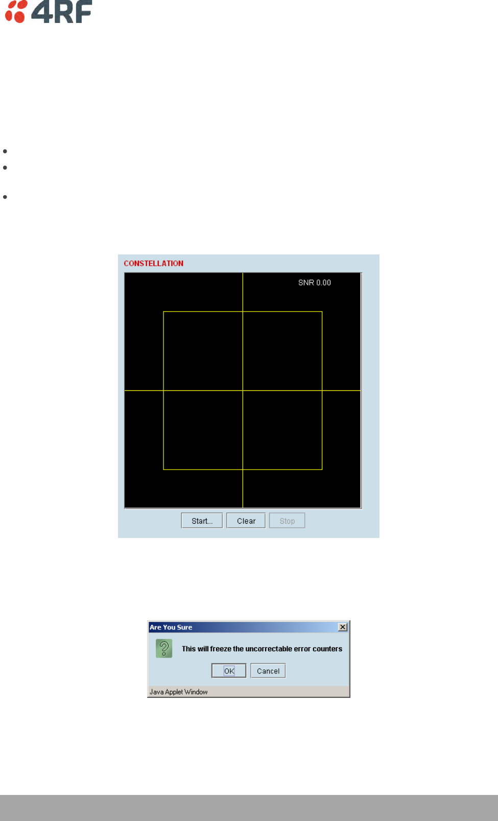
In-Service Commissioning | 207
Aprisa XE User Manual
Checking the Link Performance
For a graphical indication of the link performance, you can use the constellation analyzer.
The 'dots' are a graphical indication of the quality of the demodulated signal. Small dots that are close
together indicate a good signal. If the dots become spaced further apart, this indicates that the signal
quality is degrading. This signal quality degradation can be caused by low Rx signal level due to, for
example:
external interference
failure of any of the following: modem, receiver, far end transmitter, an antenna (either end), a
feeder or connector (for example, due to water damage)
path issues such as multipath fading or obstructions
To check the performance of the link using the constellation analyzer:
1. Select Link or Local or Remote > Performance > Constellation.
2. Click Start to start the constellation analyzer.
While the constellation analyzer is running, the terminal will temporarily stop collecting error
performance statistics. If you want to run the constellation analyzer anyway, click OK when you see
this warning message:
3. Click Stop to stop the constellation analyzer.
The terminal automatically resumes collecting error performance statistics.
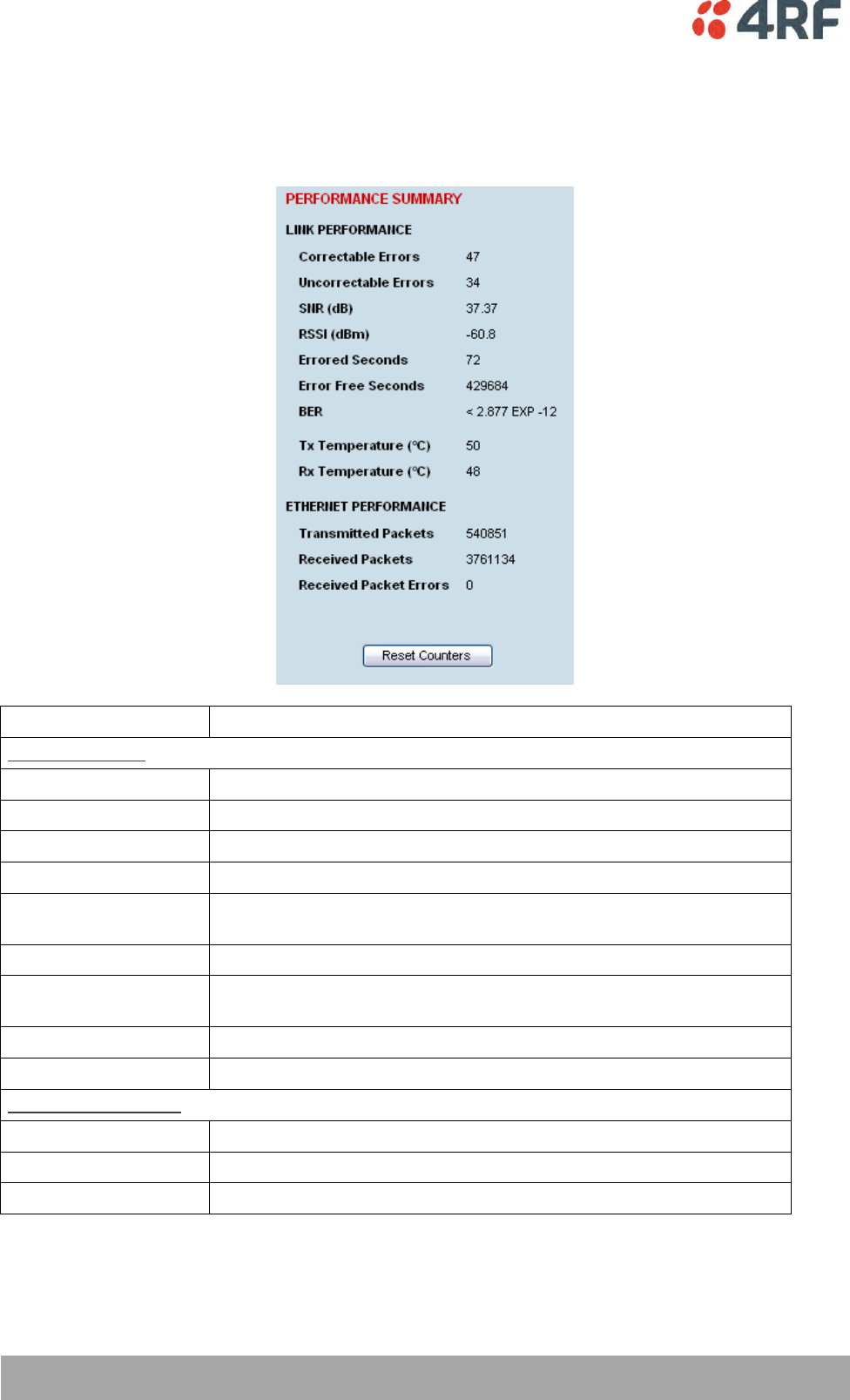
208 | In-Service Commissioning
Aprisa XE User Manual
Viewing a Summary of the Link Performance
To view the performance summary for a terminal:
Select Link or Local or Remote > Performance > Summary.
Field
Explanation
Link Performance
Correctable errors
The total number of correctable blocks since the last reset
Uncorrectable errors
The total number of uncorrectable blocks since the last reset
SNR (dB)
The Signal to Noise Ratio of the link in dB
RSSI (dBm)
The Received Signal Strength Indication at the Rx input in dBm
Errored seconds
The total number of operational seconds with errored traffic since the
last reset
Error free seconds
The total number of error free operational seconds since the last reset
BER
The system will report an estimated Bit Error Rate up to a maximum of
1 in 1021
TX temperature
The measured temperature in the transmitter module in °C
RX temperature
The measured temperature in the receiver module in °C
Ethernet performance
Transmitted packets
The total number of transmitted Ethernet packets
Received packets
The total number of received Ethernet packets
Received packet errors
The total number of packets received with errors
Click Reset Counters to reset the error counters to zero.
In-Service Commissioning | 209
Aprisa XE User Manual
Saving the History of the Link Performance
Link performance history data is stored in a rolling buffer which can be saved as a *.cvs file (default
filename is savedPerformanceHistory.csv). The maximum history data buffer is 1 week of 1 hour records
and the last hour is displayed in minute records.
The parameters saved are:
Date / Time
SNR (minimum over period)
SNR (average over period)
SNR (maximum over period)
RSSI (minimum over period)
RSSI (average over period)
RSSI (maximum over period)
BER (value at end of period)
UCEs count (value at end of period)
Transmitter temperature (value at end of period)
To save the history of the link performance for a terminal:
Select Local > Performance > Save History.
Example of file (simulated fade data):
PREVIOUS WEEK
TIME
SNR min
(dB)
SNR avg
(dB)
SNR max
(dB)
RSSI min
(dBm)
RSSI avg
(dBm)
RSSI max
(dBm)
BER UCEs
Tx Temp
(deg C)
Mon Apr 6 09:44:50 2009 35.14 35.26 35.39 -54.00 -54.00 -54.00 3.40E-12 144 50
Mon Apr 6 10:44:50 2009 35.14 35.26 35.40 -54.00 -53.90 -53.90 3.39E-12 144 50
Mon Apr 6 11:44:50 2009 35.14 35.26 35.40 -54.00 -53.90 -53.90 3.38E-12 144 50
Mon Apr 6 12:44:51 2009 15.31 25.77 58.54 -114.00 -77.00 -54.00 1.58E-05 1045 50
Mon Apr 6 13:44:51 2009 22.52 22.75 22.89 -84.10 -83.70 -83.60 6.92E-06 9912 51
Mon Apr 6 14:44:51 2009 16.20 26.05 54.61 -87.10 -77.40 -60.20 9.67E-05 72125 52
…
PREVIOUS HOUR
TIME
SNR min
(dB)
SNR avg
(dB)
SNR max
(dB)
RSSI min
(dBm)
RSSI avg
(dBm)
RSSI max
(dBm)
BER UCEs
Tx Temp
(deg C)
Mon Apr 6 14:11:51 2009 22.52 28.38 22.75 -84.10 -78.19 -83.80 5.89E-06 22821 52
Mon Apr 6 14:12:51 2009 22.55 25.67 22.75 -84.10 -80.89 -83.80 5.86E-06 23369 52
Mon Apr 6 14:13:51 2009 22.50 23.52 22.75 -84.10 -83.07 -83.70 5.84E-06 23847 52
Mon Apr 6 14:14:51 2009 22.50 24.35 22.78 -84.10 -82.23 -83.70 5.81E-06 24338 52
Mon Apr 6 14:15:51 2009 22.54 22.73 22.77 -84.10 -83.86 -83.80 5.78E-06 24855 52
Mon Apr 6 14:16:51 2009 22.52 26.67 22.75 -84.10 -79.90 -83.80 5.75E-06 25374 52
Mon Apr 6 14:17:51 2009 22.48 30.19 22.79 -84.10 -76.38 -83.70 5.73E-06 25918 52
Mon Apr 6 14:18:51 2009 22.49 28.87 22.74 -84.10 -77.68 -83.80 5.71E-06 26473 52
Mon Apr 6 14:19:51 2009 22.48 30.65 22.74 -84.10 -75.94 -83.80 5.68E-06 27007 52
Mon Apr 6 14:20:51 2009 22.50 29.99 22.75 -84.00 -76.59 -83.80 5.66E-06 27561 52
Mon Apr 6 14:21:51 2009 22.61 29.78 22.76 -84.00 -76.82 -83.80 5.64E-06 28167 52
Mon Apr 6 14:22:51 2009 22.46 25.70 22.74 -84.10 -80.86 -83.90 5.62E-06 28717 52
Mon Apr 6 14:23:51 2009 22.46 26.96 22.75 -84.10 -79.61 -83.80 5.59E-06 29237 52
Mon Apr 6 14:24:51 2009 22.47 24.71 22.75 -84.10 -81.86 -83.80 5.57E-06 29776 52
Mon Apr 6 14:25:51 2009 22.48 30.19 22.73 -84.10 -76.36 -83.80 5.55E-06 30368 52
Mon Apr 6 14:26:51 2009 22.49 25.97 22.75 -84.20 -80.61 -83.80 5.53E-06 30942 52
Mon Apr 6 14:27:51 2009 16.20 22.94 54.61 -87.10 -83.76 -83.90 7.30E-06 71751 52
Mon Apr 6 14:28:51 2009 16.23 26.84 49.90 -87.00 -73.31 -60.30 6.67E-03 72125 52
Mon Apr 6 14:29:51 2009 35.10 40.60 35.24 -60.50 -54.96 -60.30 1.70E-03 72125 52
Mon Apr 6 14:30:51 2009 35.08 39.17 35.28 -60.50 -56.40 -60.30 9.13E-04 72125 52
Mon Apr 6 14:31:51 2009 35.07 36.63 35.26 -60.50 -58.95 -60.20 6.11E-04 72125 52
Mon Apr 6 14:32:51 2009 35.06 36.68 35.24 -60.60 -58.90 -60.30 4.52E-04 72125 52
Mon Apr 6 14:33:51 2009 35.06 35.34 35.25 -60.60 -60.24 -60.30 3.56E-04 72125 52
Mon Apr 6 14:34:51 2009 35.09 36.28 35.24 -60.50 -59.28 -60.30 2.92E-04 72125 52
Mon Apr 6 14:35:51 2009 35.07 42.56 35.28 -60.60 -53.03 -60.30 2.46E-04 72125 52
…

210 | In-Service Commissioning
Aprisa XE User Manual
To save the alarm history from the Remote terminal, login to the Remote terminal and Select Local >
Alarms > Save History.
In-Service Commissioning | 211
Aprisa XE User Manual
To create an Excel chart of the link performance for a terminal:
1. Open the *.csv file with Excel.
2. Select the ‘Time’ column and the column you wish to graph e.g. ‘SNR avg (dB)’ or ‘RSSI avg (dBm)’
3. Select ‘Insert Chart’ from the Excel menu.
Graph of Date / Time vs the average SNR
0.00
5.00
10.00
15.00
20.00
25.00
30.00
35.00
40.00
45.00
Mon Apr 6 14:11:51 2009
Mon Apr 6 14:12:51 2009
Mon Apr 6 14:13:51 2009
Mon Apr 6 14:14:51 2009
Mon Apr 6 14:15:51 2009
Mon Apr 6 14:16:51 2009
Mon Apr 6 14:17:51 2009
Mon Apr 6 14:18:51 2009
Mon Apr 6 14:19:51 2009
Mon Apr 6 14:20:51 2009
Mon Apr 6 14:21:51 2009
Mon Apr 6 14:22:51 2009
Mon Apr 6 14:23:51 2009
Mon Apr 6 14:24:51 2009
Mon Apr 6 14:25:51 2009
Mon Apr 6 14:26:51 2009
Mon Apr 6 14:27:51 2009
Mon Apr 6 14:28:51 2009
Mon Apr 6 14:29:51 2009
Mon Apr 6 14:30:51 2009
Mon Apr 6 14:31:51 2009
Mon Apr 6 14:32:51 2009
Mon Apr 6 14:33:51 2009
Mon Apr 6 14:34:51 2009
Mon Apr 6 14:35:51 2009
SNR avg (dB)
Date / Time
Aprisa XE Link Performance
Graph of Date / Time vs the average RSSI
-90.00
-80.00
-70.00
-60.00
-50.00
-40.00
-30.00
-20.00
-10.00
0.00
Mon Apr 6 14:11:51 2009
Mon Apr 6 14:12:51 2009
Mon Apr 6 14:13:51 2009
Mon Apr 6 14:14:51 2009
Mon Apr 6 14:15:51 2009
Mon Apr 6 14:16:51 2009
Mon Apr 6 14:17:51 2009
Mon Apr 6 14:18:51 2009
Mon Apr 6 14:19:51 2009
Mon Apr 6 14:20:51 2009
Mon Apr 6 14:21:51 2009
Mon Apr 6 14:22:51 2009
Mon Apr 6 14:23:51 2009
Mon Apr 6 14:24:51 2009
Mon Apr 6 14:25:51 2009
Mon Apr 6 14:26:51 2009
Mon Apr 6 14:27:51 2009
Mon Apr 6 14:28:51 2009
Mon Apr 6 14:29:51 2009
Mon Apr 6 14:30:51 2009
Mon Apr 6 14:31:51 2009
Mon Apr 6 14:32:51 2009
Mon Apr 6 14:33:51 2009
Mon Apr 6 14:34:51 2009
Mon Apr 6 14:35:51 2009
RSSI avg (dBm)
Date / Time
Aprisa XE Link Performance
To clear the history of the link performance for a terminal:
Select Link or Local or Remote > Performance > Clear History.
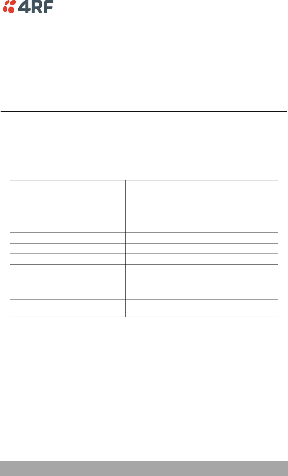
Maintenance | 213
Aprisa XE User Manual
13. Maintenance
There are no user-serviceable components within the terminal.
All hardware maintenance must be completed by 4RF or an authorized service centre.
Do not attempt to carry out repairs to any boards or parts.
Return all faulty terminals to 4RF or an authorized service centre.
For more information on maintenance and training, please contact Customer Services.
CAUTION: Electro Static Discharge (ESD) can damage or destroy the sensitive electrical components in the
terminal.
Routine Maintenance
Every six or twelve months, for both ends of the link, you should record the RSSI and SNR levels as well as
checking the following:
Item
What to check or look for
Equipment shelter environment
Water leaks
Room temperature
Excessive vibration
Vermin damage
Terminal mounting
Firmly mounted
Antenna cable connections
Tight and dry
Antenna cable and its supports
Not loose or suffering from ultra-violet degradation
Antenna and its mounting hardware
Not loose, rusty or damaged
Safety earth
Connections tight
Cabling intact
DC system
Connections tight
Voltage in normal limits
Batteries (if installed)
Connections tight
Electrolyte levels normal
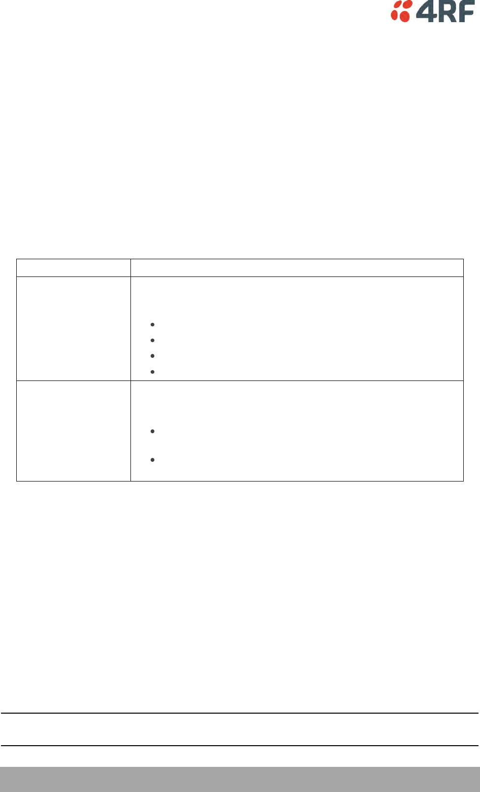
214 | Maintenance
Aprisa XE User Manual
Terminal Upgrades
You can upgrade all software for both terminals remotely (through a management network), which
eliminates the need to physically visit either end of the link.
A terminal is upgraded by accessing a running TFTP server (see ‘TFTP Upgrade Process’ on page 221). All
the required files are uploaded from the TFTP server into the terminal and then activated following a
terminal reboot.
System files can be manually uploaded (see ‘Uploading System Files’ on page 226‘).
Inventory File
Software release 8.2.10 and all future software releases, contains an inventory file (similar to a manifest
file) which is used to validate the software files in the terminal.
To view the Software Status of the terminal:
Select Link, Local or Remote > Summary
Software status
Function
Standard Software
Release
The software status indicates ‘Standard Software Release’ if the
following system software files have not been changed since the last
TFTP Upgrade.
Kernel image file
Software image file
Firmware image files
Configuration files
Modified Software
Release
The software status indicates ‘Modified Software Release’ if the system
software files have been changed since the last TFTP Upgrade.
This could be caused by:
an image file which has been uploaded to the terminal since the
last TFTP upgrade which is not part of that upgrade.
an image file which was part of the last TFTP upgrade but was
subsequently deleted.
Upgrade Prerequisites
To minimize disruption of link traffic and prevent your terminals from being rendered inoperative, please
follow the procedures described in this section together with any additional information or instructions
supplied with the upgrade package.
Before upgrading the terminal, ensure that you have saved the configuration file (see ‘Saving the
terminal's configuration’ on page 89) as well as the cross connection configuration (see ‘Saving cross
connection configurations’ on page 155).
The Remote terminal upgrade process will be faster if the bandwidth allocated to the management
ethernet capacity is maximized.
The terminal software must be identical at both ends of the link.
At the end of the terminal upgrade process, the versions of image files (kernel software, and firmware)
that were in use before the upgrade are still in the terminal. You can restore them, if required, by editing
the image tables and reactivating the old files (see ‘Changing the Status of an Image ’ on page 232).
IMPORTANT NOTE: Ensure you are logged into the Near end terminal as Admin before you start an
upgrade.

Maintenance | 215
Aprisa XE User Manual
Software Upgrade Process
Unzip and save the following folders to your hard drive:
8.6.77 Software
tftpd32.exe
The following steps are required for the software upgrade process:
1. Identify the correct TFTP upgrade type (see ‘Identifying the Correct TFTP Upgrade Type’ on page
217).
2. If the terminals are operating software prior to 8.3.40:
Upload the Root File System (see ‘Uploading the Root File System’ on page 216)
Upload the Motherboard Images (see ‘Uploading the Motherboard Images’ on page 216).
Reboot the terminal.
3. Go through the steps of the TFTP upgrade process (see ‘TFTP Upgrade Process’ on page 221).
4. Upgrade for new FXO/FXS and modem images
5. Reboot the terminal.
6. Clear the Java and web browser caches (see ‘Step 7: Clear the Java and web browser caches’ on
page 223).
If the TFTP upload process fails, an ‘Upload Fail’ alarm is raised. If the TFTP upload process fails due to a
power failure, the alarm is raised upon power recovery.
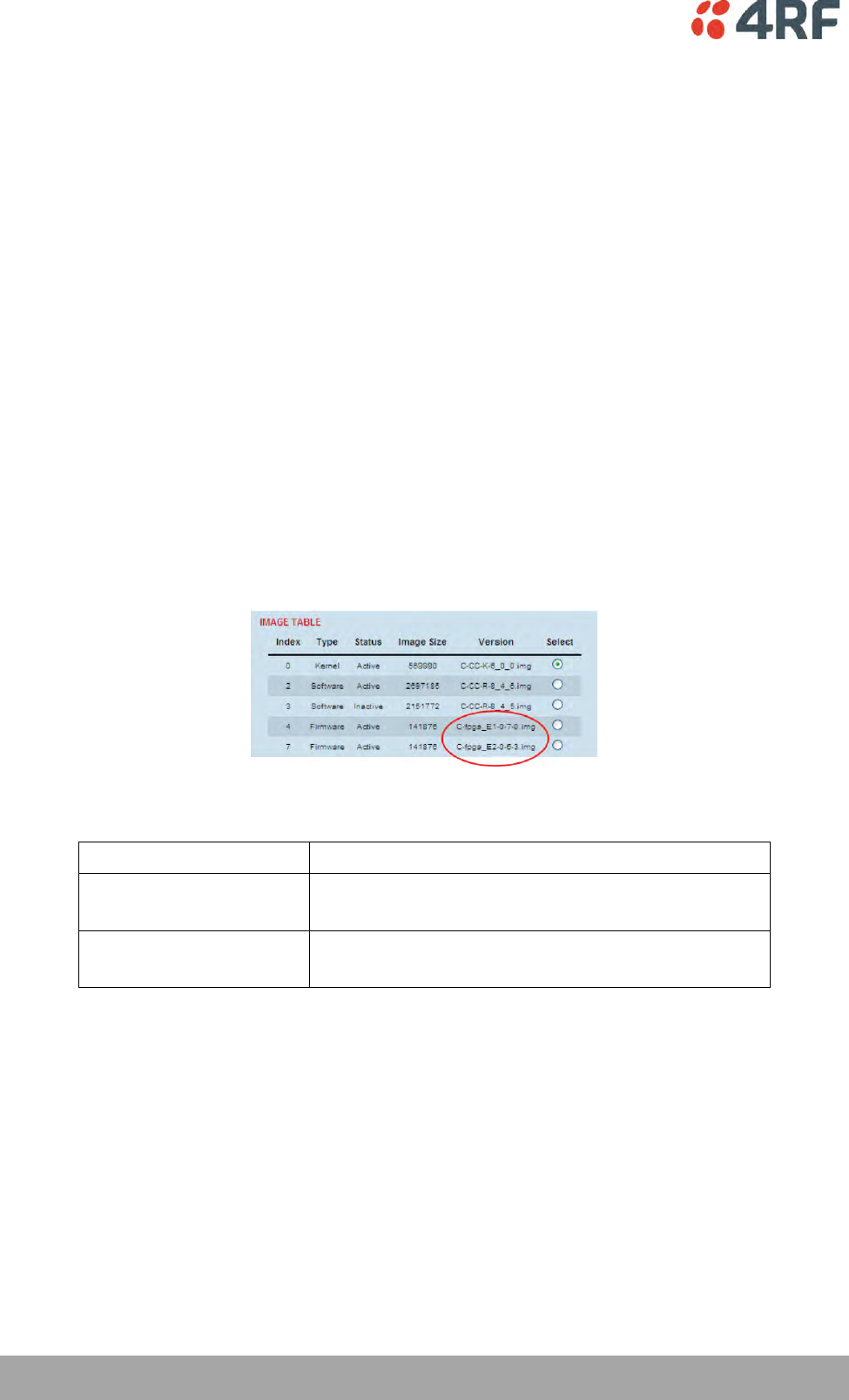
216 | Maintenance
Aprisa XE User Manual
Uploading the Root File System
Note: Uploading of image files can only be performed to the local terminal i.e. not via the link to the
remote terminal.
1. Logon to the local terminal as admin.
2. Go to SuperVisor > Local > Maintenance > Upload > Software.
3. Browse to the 8.6.77 Software folder and select ‘C-CC-R-8_6_7.img’.
4. Click Upload and wait for the upload status to display Succeeded.
5. Activate the ‘C-CC-R-8_6_7.img’ with SuperVisor Local > Maintenance > Image Table (see ‘Changing
the Status of an Image File’ on page 232).
Uploading the Motherboard Images
The E1 and E2 motherboard images do not update as part of the TFTP upgrade.
Check if the correct motherboard images are loaded with SuperVisor Local > Maintenance > Image Table.
Example: Radio on V8.4.60 with a Rev C motherboard.
The Motherboard Firmware images for this software version are:
Motherboard Type
Image Files Required
Rev C
C-fpga_E1-0-7-0.img (Motherboard 1
C-fpga_E2-0-5-3.img (Motherboard 2)
Rev D
C-fpga_E1-1-7-3.img (Motherboard 1
C-fpga_E2-1-5-4.img (Motherboard 2)
If the motherboard image files are not correct, upload the relevant image files.
Note: Uploading of image files can only be performed to the local terminal i.e. not via the link to the
remote terminal.
1. Logon to the local terminal as admin
2. Go to SuperVisor > Local > Maintenance > Upload > Firmware.
3. Browse to the 8.6.77 Software folder and select ‘C-fpga_Ex-x-x-x.img’.
4. Click Upload and wait for the upload status to display Succeeded.
5. Activate the ‘C-fpga_Ex-x-x-x.img’ with SuperVisor Local > Maintenance > Image Table (see ‘Changing
the Status of an Image File’ on page 232).

Maintenance | 217
Aprisa XE User Manual
Identifying the Correct TFTP Upgrade Type
The correct TFTP upgrade type will depend on both the Bootloader Version and the Software Version
Type.
Aprisa XE terminals running the older bootloader software (bootloader version 0) have a limitation on the
number of software images that can be loaded simultaneously into a terminal.
Identifying the Bootloader Version
Determine which bootloader version your terminal is running by using the SuperVisor menu item
Maintenance > Support Summary and look for the ‘Bootloader Version’ number:
(1) If your terminal is running bootloader version 1 or greater, use the TFTP full upgrade process.
(2) If your terminal is running bootloader version 0 and running a software version prior to 7.0.6,
use the TFTP partial upgrade process.
(3) If your terminal is running bootloader version 0 and running a software version 7.0.6 or later,
use the TFTP standard upgrade process.
(4) HSD terminals cannot run with bootloader version 0.
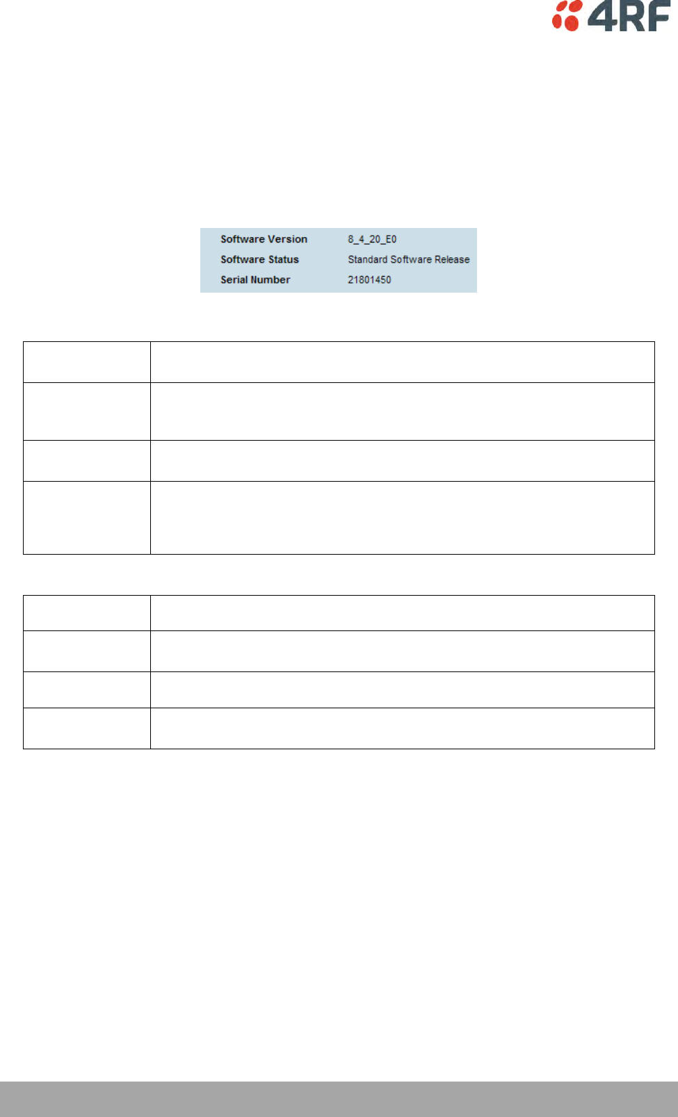
218 | Maintenance
Aprisa XE User Manual
Identifying the Software Version Type
There are six different software version types; ETSI type 1, ETSI type 1 HSD, ETSI type 2, ETSI type 2 HSD,
FCC Part 101 and FCC Part 90.
To determine which Software Version Type is currently installed on the terminal, take note of the
‘Software Version’ on SuperVisor Summary page. The last three characters indicate the Software Version
Type.
ETSI Compliance Body
8_6_77_E0
The E0 variant supports ETSI (Type 1) 1+0 and MHSB terminals with the same
variants as Aprisa XE software version 8.4.40.
8_6_77_E1
The E1 variant supports ETSI (Type 2) 1+0 and MHSB terminals with the same
variants as Aprisa XE software version 8.4.40 except for the 400 MHz 25 kHz
and 50 kHz which has been replaced with 900 MHz 25 kHz and 50 kHz.
8_6_77_E0h
The E0h variant supports ETSI (Type 1) Hitless Space Diversity (HSD)
terminals with the same variants as Aprisa XE software version 8.4.40.
8_6_77_E1h
The E1 variant supports ETSI (Type 2) Hitless Space Diversity (HSD) terminals
with the same variants as Aprisa XE software version 8.4.40 except for the
400 MHz 25 kHz and 50 kHz which has been replaced with 900 MHz 25 kHz
and 50 kHz.
FCC Compliance Body
8_6_77_F0
The F0 variant supports FCC part 90 1+0 and MHSB terminals.
8_6_77_F0h
The F0h variant supports FCC part 90 Hitless Space Diversity (HSD)
terminals.
8_6_77_F1
The F1 variant supports FCC part 101 1+0 and MHSB terminals.
8_6_77_F1h
The F1h variant supports FCC part 101 Hitless Space Diversity (HSD)
terminals.
Maintenance | 219
Aprisa XE User Manual
Upgrade Version Files
The following table defines the purpose of the upgrade version files:
Upgrade Version File
Upgrade Type
Software Version Type
8_6_77_E0a
Full TFTP upgrade
ETSI TYPE 1
8_6_77_E0
Standard TFTP upgrade
ETSI TYPE 1
8_6_77_E0h
Standard TFTP upgrade
ETSI TYPE 1 HSD
8_6_77_E0p
Partial TFTP upgrade
ETSI TYPE 1
8_6_77_E1a
Full TFTP upgrade
ETSI TYPE 2
8_6_77_E1
Standard TFTP upgrade
ETSI TYPE 2
8_6_77_E1h
Standard TFTP upgrade
ETSI TYPE 2 HSD
8_6_77_E1p
Partial TFTP upgrade
ETSI TYPE 2
8_6_77_F0a
Full TFTP upgrade
FCC Part 90
8_6_77_F0
Standard TFTP upgrade
FCC Part 90
8_6_77_F1a
Full TFTP upgrade
FCC Part 101
8_6_77_F1
Standard TFTP upgrade
FCC Part 101
Installing RF Synthesizer Configuration Files
If you are upgrading from a software version prior to 7_1_x, you will need to install new RF synthesizer
files, refer to ‘Configuration Files’ on page 226.
You can then upgrade the terminal using TFTP (see page 221).
Frequency Band
Synthesizer File(to be installed)
Comments
300, 400 MHz
XE_300_400_type_1_synth.cfg
BB synthesizer
300, 400 MHz
XE_300_400_type_2_synth.cfg
E3 synthesizer
300, 400 MHz
XE_300_400_type_3_synth.cfg
5 kHz sythesizer step
600, 700, 800, 900 MHz
XE_600_700_800_900_synth.cfg
1400 MHz
XE_1400_synth.cfg
1400 MHz
XE_1400TCVR_synth.cfg
New transceiver (introduced
April 2012)
1800 MHz
XE_1800_synth.cfg
2000, 2500 MHz
XE_2000_2500_synth.cfg

220 | Maintenance
Aprisa XE User Manual
TFTP Upgrade Process Types
TFTP partial upgrade process
Run the TFTP upgrade process by typing 8_6_77_E0p in the Upgrade Version field.
This will perform a partial upgrade which will delete unnecessary image files that might be taking up
space in the Image Table (which could prevent a standard upgrade succeeding).
Reboot the terminal.
Run a TFTP standard upgrade process on the terminal.
Reboot the terminal again.
TFTP standard upgrade process
This TFTP standard upgrade process excludes FPGA images for the newly introduced revisions of the
Modem, DFXO and DFXS cards.
Run the TFTP upgrade process by typing ‘8_6_77_E0’ in the Upgrade Version field.
If the standard upgrade fails, it may be necessary to make space for the new images by manually deleting
‘Inactive’ firmware image files.
To delete a firmware image file, select the SuperVisor menu item Maintenance > Image Table, select the
firmware image and click on Edit. Set the IMAGE DETAILS Command to ‘Delete’ and click ‘Apply’.
Reboot the terminal.
Additional TFTP upgrade options have been provided to load the new images separately. Run the TFTP
upgrade process using the file:
‘F1_8_6_7’ to load images for the newest DFXO and DFXS cards (rev D).
‘F2_8_6_7’ to load images for all revisions of DFXO and DFXS cards.
‘F3_8_6_7’ to load images for the newest Modem card (rev D).
Reboot the terminal again.
TFTP full upgrade process
Run the TFTP upgrade process for 1+0 and MHSB terminals by typing ‘8_6_77_E0a’ in the Upgrade Version
field.
Run the TFTP upgrade process for HSD terminals by typing ‘8_6_77_E0h’ in the Upgrade Version field.
Reboot the terminal.
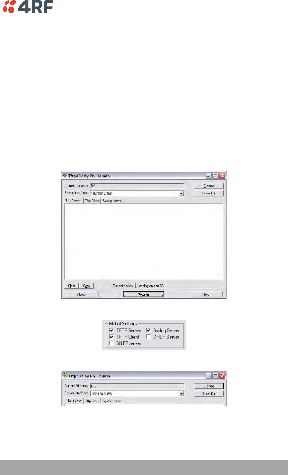
Maintenance | 221
Aprisa XE User Manual
TFTP Upgrade Process
To upgrade a terminal using the TFTP:
1. Run the TFTP server.
2. Login to the Near end terminal / local terminal (see ‘IP Addressing of Terminals’ on page 53).
3. Run the TFTP upgrade process on the Remote terminal.
4. Reboot the Remote terminal.
5. Run the TFTP upgrade process on the Local terminal.
6. Reboot the Local terminal.
7. Clear the Java and web browser caches.
Step 1: Run the TFTP server
1. Double-click tftpd32.exe (located in the TFTPD directory) from the Aprisa CD supplied with the
product. Leave the TFTPD32 application running until the end of the upgrade process.
2. Click Settings and make sure that both SNTP server and DHCP server are not selected (no tick), and
click OK.
3. Click Browse and navigate to the root directory on the Aprisa CD (for example, D:\) supplied with the
product, then click OK.
4. Note down the IP address of the TFTP server (shown in the Server Interfaces drop-down list in the
TFTPD32 window) as you will need it later.
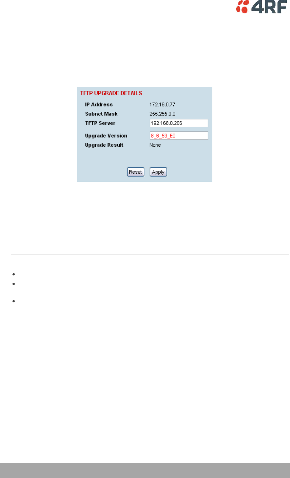
222 | Maintenance
Aprisa XE User Manual
Step 2: Log into the Local terminal
Use SuperVisor to log into the Near end terminal (now the Local terminal) (see ‘IP Addressing of
Terminals’ on page 53) with either 'modify' or 'admin' privileges.
Step 3: Run the TFTP upgrade process on the Remote terminal
1. Select Remote > Maintenance > Upload > TFTP Upgrade.
2. Enter the IP address of the TFTP server.
3. Enter the version number of the software that you are upgrading to as a three digit number separated
by underscores, for example, 8_6_77_E0 for ETSI variants.
4. Click Apply and check the TFTP server for download activity.
The Upgrade Result changes from 'Executing' to either 'Succeeded' or 'Failed'.
Note: This may take several minutes when upgrading the remote terminal.
If the upgrade has failed:
The TFTP server IP address may be set incorrectly
The 'Current Directory' on the TFTP server was not pointing to the location of the upload config file
e.g. 'Rel_8_6_77_E0.cfg' .
There may not be enough free space in the image table to write the file. Inactive images can be
deleted (and the terminal rebooted) to free up space for the new image (see ‘Changing the Status
of an Image File’ on page 232).
Step 4: Reboot the Remote terminal
Reboot the remote terminal before proceeding with the next step of the upgrade process (see ‘Rebooting
the Terminal’ on page 233).
1. Select Remote > Maintenance > Reboot and select [Hard Reboot]
Communications to SuperVisor remote page will fail until the remote terminal reboot has completed.
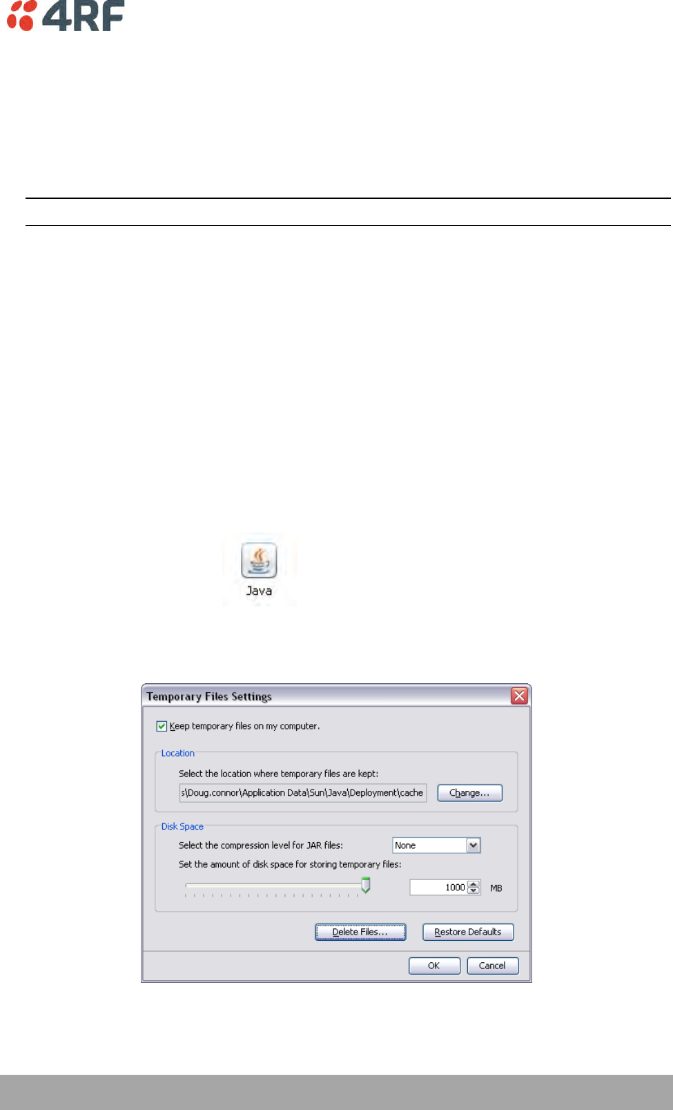
Maintenance | 223
Aprisa XE User Manual
Step 5: Run the TFTP upgrade process on the Local terminal.
1. Select Local > Maintenance > Upload > TFTP Upgrade.
2. Enter the IP address of the TFTP server (that you noted earlier)
3. Enter the version number of the software (that you are upgrading to) for example, 8_6_77_E0.
4. Click Apply and check the TFTP server for download activity.
The Upgrade Result changes from 'Executing' to either 'Succeeded' or 'Failed'.
Note: This may take several minutes when upgrading the remote terminal.
Step 6: Reboot the Local terminal
Reboot the local terminal before proceeding with the next step of the upgrade process (see ‘Rebooting
the Terminal’ on page 233).
1. Select Local > Maintenance > Reboot and select [Hard Reboot]
2. Log back into the Local terminal when the reboot has completed.
Step 7: Clear the Java and web browser caches
After upgrading the terminal you should clear the Java and web browser caches. The files stored in them
may cause the SuperVisor and Cross Connections applications to display incorrectly.
To clear the Java cache (Windows XP, Java 1.6):
1. Select Start > Control Panel.
2. Select Java
3. Click the General tab.
4. In the ‘Temporary Internet Files’, click Settings
5. Click on ‘Delete Files’ (‘Applications and Applets’ and ‘Trace and Log Files’ both ticked) and OK to
confirm.
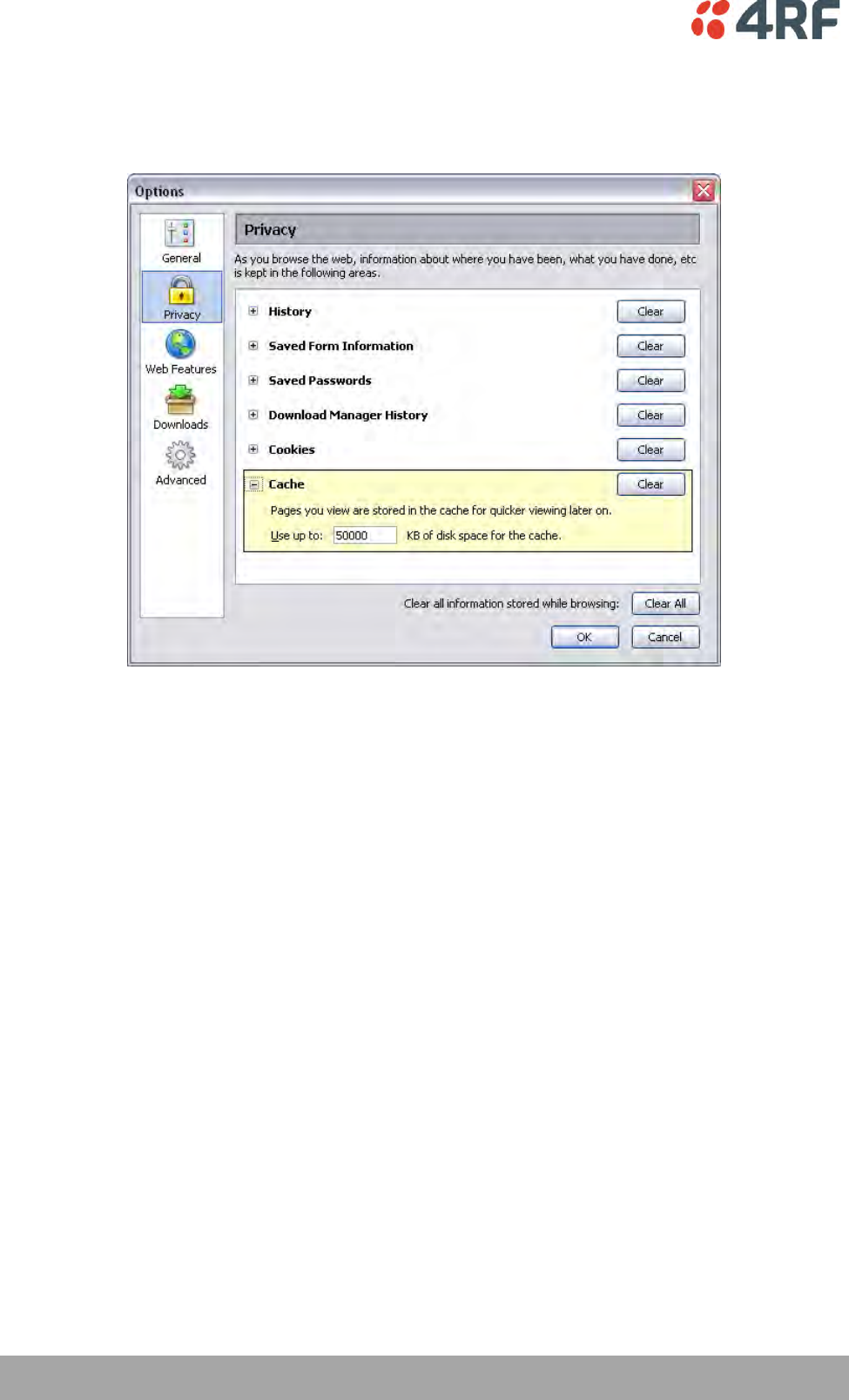
224 | Maintenance
Aprisa XE User Manual
To clear your web browser cache (Mozilla Firefox 1.x and above):
1. Select Tools > Options.
2. Select Privacy and then click Cache.
3. Click Clear to clear the cache, and then click OK to confirm.
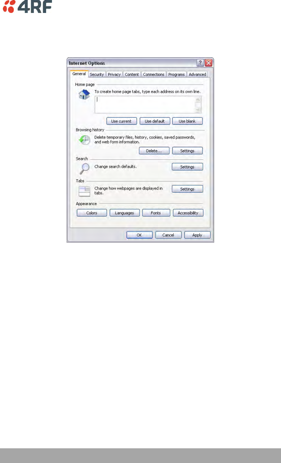
Maintenance | 225
Aprisa XE User Manual
To clear your web browser cache (Internet Explorer 7.0 and above):
1. Select Tools > Internet Options.
2. On the General tab
3. In Browsing history, click Delete
4. In the ‘Temporary Internet Files’, click Delete Files and Yes to confirm.

226 | Maintenance
Aprisa XE User Manual
Uploading System Files
System files e.g. configuration files, kernel image files, software image files and firmware image files can
be uploaded manually.
Note: You should only upgrade components that need changing. It is not always necessary, for instance, to
replace kernel or software files when upgrading a single firmware file. If interdependency exists between
file types, this will be made clear in the documentation that accompanied the update package.
Configuration Files
Configuration files (.cfg) are compressed archives containing a script to instruct the terminal on how to
handle the other files in the archive.
Uploading of configuration files can only be performed to the Local Terminal (not via the link to the
Remote Terminal).
RF synthesizer configuration files
The RF synthesizer configuration archive contains files that provide values for the transmitter and receiver
synthesizers to operate across the supported frequency bands.
Synthesizer configuration filenames have the following format:
XE_(frequency bands)_synth.cfg
e.g. XE_300_400_synth.cfg
Modem configuration files
The Modem configuration archive contains files that provide values for the Modem to operate at the
various supported channel sizes and modulation types.
Modem configuration filenames have the following format:
modem_(version number).cfg
e.g. modem_8_3_1.cfg (ETSI variants)
Cross-connect configuration files
The Cross-connect configuration archive contains the Cross Connections application program that can be
launched from within SuperVisor.
Cross-connect configuration filenames have the following format:
C-crossconnect_(version number).cfg
e.g. C-crossconnect_8_6_7.cfg
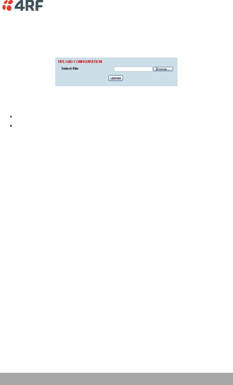
Maintenance | 227
Aprisa XE User Manual
To upload a configuration file:
1. Select Local > Maintenance > Config Files > Upload Configuration
2. Browse to the location of the file required to be uploaded into the terminal *.cfg.
3. Click on Upload.
The normal response is Succeeded if the file has been loaded correctly.
A response of ‘Failed’ could be caused by:
Not enough temporary space in the filesystem to uncompress the archive and execute the script
A file or directory expected by the script not being present on the filesystem
4. Reboot the terminal using a ‘Hard Reboot’ (see ‘Rebooting the Terminal’ on page 233).
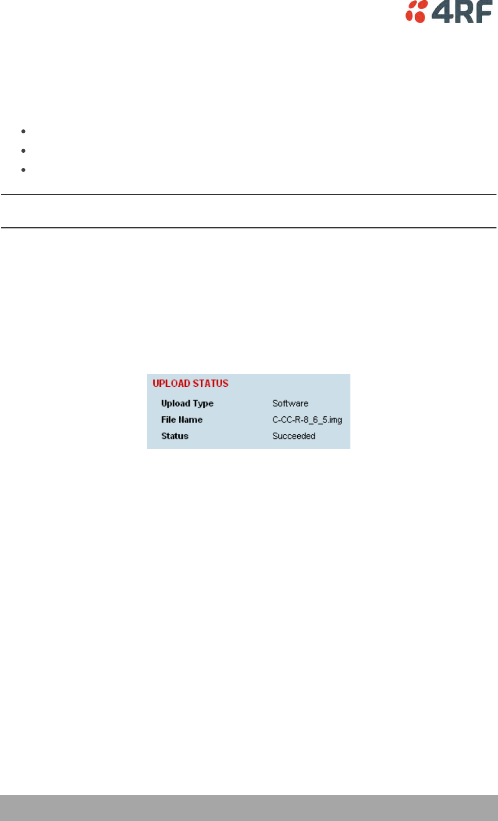
228 | Maintenance
Aprisa XE User Manual
Image Files
Image files (.img) are loaded into the terminal and either contains code that is executed by the system
processor, or contain instructions to configure the various programmable logic elements. The image file
types that can be uploaded are:
Kernel image files
Software image files
Firmware image files
Note: The Bootloader image file C-CC-B-(version number).srec and Flash File System image file C-CC-F-
(version number).img can only be changed in the factory.
Uploading of image files can only be performed to the local terminal (not via the link to the remote
terminal).
To upload and activate an image file:
1. Upload the required image file.
If the Upload Status page show ‘executing’, then ‘writing to flash’, then ‘Succeeded’, then the file has
been written into the image table correctly.
If the Upload Status is ‘Failed’, there may not be enough free space in the image table to write the
file. Inactive images can be deleted (and the terminal rebooted) to free up space for the new image
(see ‘Changing the Status of an Image File’ on page 232).
2. Set the status of the image to ‘activate’ (see ‘Changing the Status of an Image ’ on page 232).
This actually sets the status to ‘Selected’ until after a terminal reboot.
3. Reboot the terminal using a ‘Hard Reboot’ (see ‘Rebooting the Terminal’ on page 233).
This activates the selected image. The image table status will now show ‘Active’.
The previous image file status will now show as ‘Inactive’.
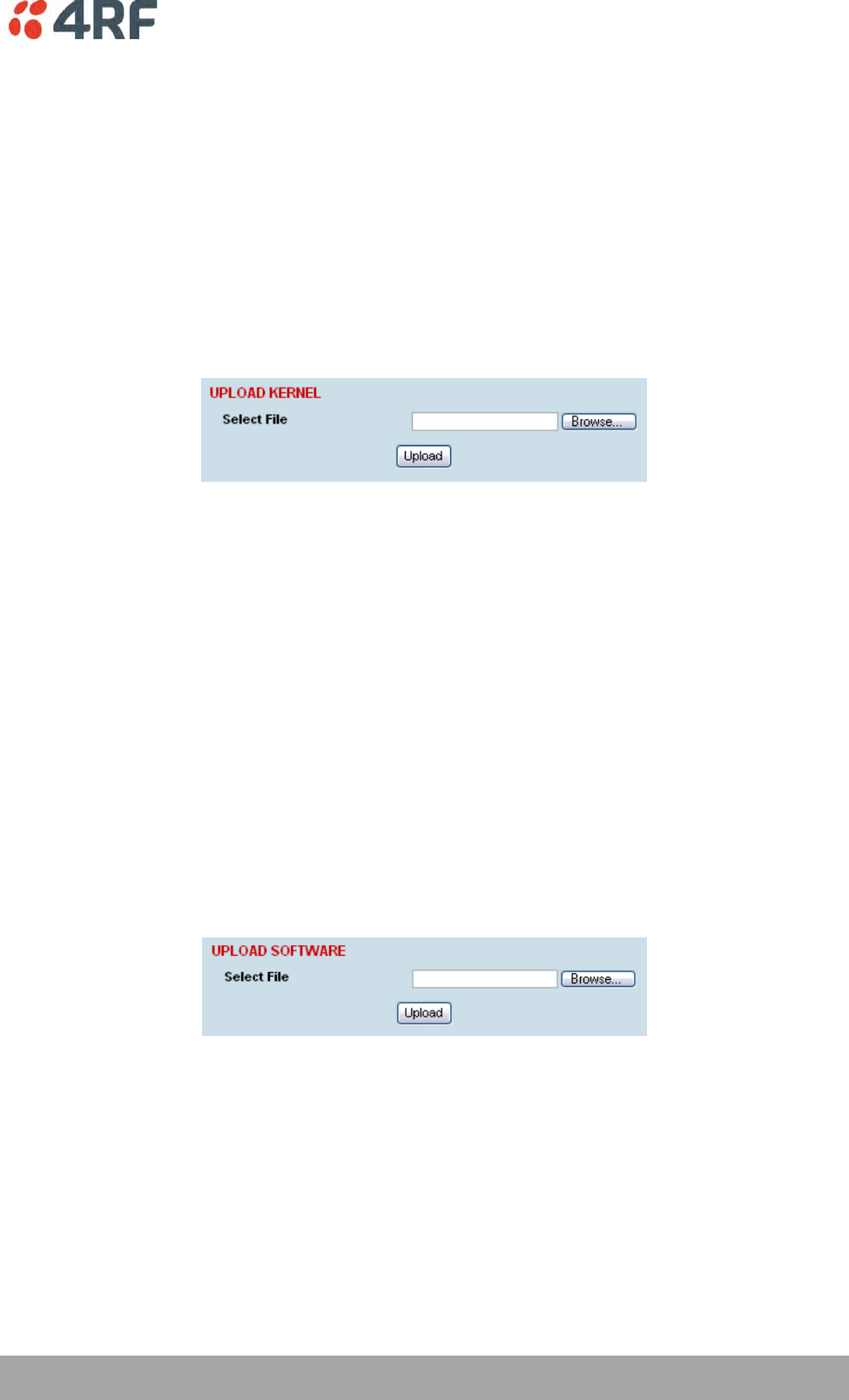
Maintenance | 229
Aprisa XE User Manual
Kernel image files
Kernel image files contain code that forms the basis of the microprocessor’s operating system. There can
only ever be two kernel image files in the image table, the active and the inactive.
Kernel filenames have the following format:
C-CC-K-(version number).img
e.g. C-CC-K-6_0_0.img
To upload a kernel image file;
1. Select Local > Maintenance > Upload > Kernel
2. Browse to the location of the file required to be uploaded into the terminal *.img.
3. Click on Upload.
4. Activate the image (see ‘Changing the Status of an Image File’ on page 232).
5. Reboot the terminal using a ‘Hard Reboot’ (see ‘Rebooting the Terminal’ on page 233).
Software image files
Software image files contain code that forms the basis of the terminal’s application and management
software (including the Web-based GUI). There can only ever be two software image files in the image
table, the active and the inactive.
Software image filenames have the following format:
C-CC-R-(version number).img
e.g. C-CC-R-8_6_7.img
To upload a software image file;
1. Select Local > Maintenance > Upload > Software
2. Browse to the location of the file required to be uploaded into the terminal *.img.
3. Click on Upload.
Software image files may take one or two minutes to upload as they can be quite large (≈ 2 Mbytes). The
size of this file has caused some Microsoft Internet Explorer proxy server setups to abort during the
software update process. To avoid this problem, either set the proxy file size limit to 'unlimited' or avoid
the use of the proxy altogether.
4. Activate the image (see ‘Changing the Status of an Image File’ on page 232).
5. Reboot the terminal using a ‘Hard Reboot’ (see ‘Rebooting the Terminal’ on page 233).
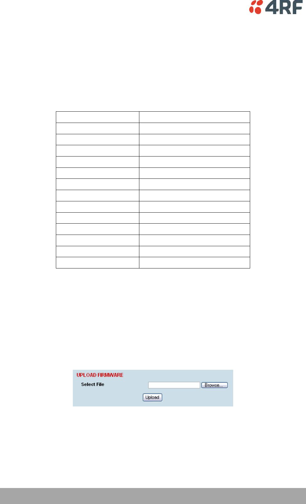
230 | Maintenance
Aprisa XE User Manual
Firmware image files
Firmware image files contain instructions to configure the various programmable logic elements in the
terminal. There can only ever be two firmware image files for the same HSC version in the image table,
the active and the inactive.
Firmware image filenames have the following format:
C-fpga_ff-x-y-z.img
e.g. C-fpga_E5-0-7-3.img
where ff indicates the function (motherboard, interface card, etc).
Function Number
Function
E1
Motherboard 1
E2
Motherboard 2
E5
QJET Interface Card
E7
Q4EM Interface Card
E8
DFXO Interface Card
E9
DFXS Interface Card
EA
Modem
EB
QV24 Interface Card
EC
HSS Interface Card
ED
PSC (component of HSD system)
EE
PIC (component of HSD system)
FA
HSD modem
FB
QV24 Sync Interface Card
where x indicates the HSC (hardware software compatibility) version.
where y indicates the firmware major revision number
where z indicates the firmware minor revision number
To upload a firmware image file;
1. Select Local > Maintenance > Upload > Firmware
2. Browse to the location of the file required to be uploaded into the terminal *.img.
3. Click on Upload.
4. Activate the image (see ‘Changing the Status of an Image File’ on page 232).
5. Reboot the terminal using a ‘Hard Reboot’ (see ‘Rebooting the Terminal’ on page 233).
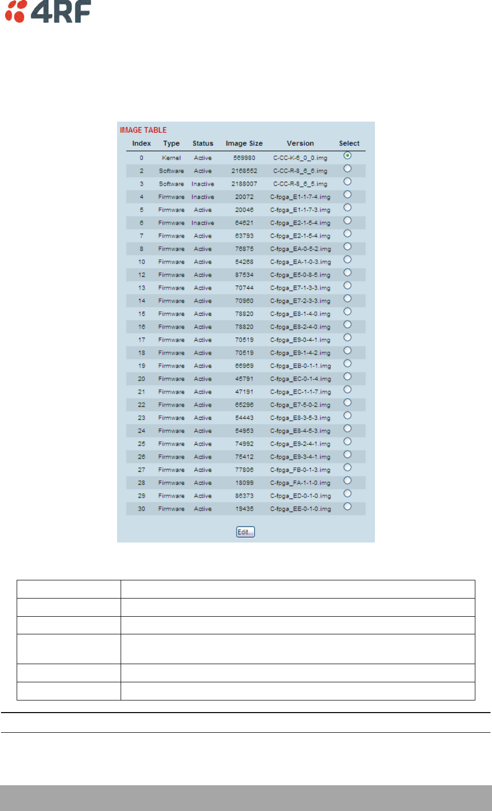
Maintenance | 231
Aprisa XE User Manual
Viewing the Image Table
To view the image table:
1. Select Link or Local or Remote > Maintenance > Image Table.
The image table shows the following information:
Heading
Function
Index
A reference number for the image file
Type
The image type ‘Kernel’, ‘Software’ or ‘Firmware’.
Status
The status of the image; 'Active', 'Inactive', ‘Selected’, ‘Current (de-
selected)’
Image Size
The image file size in bytes
Version
The image file name and version details
Note: Configuration file details do not appear in the image table.
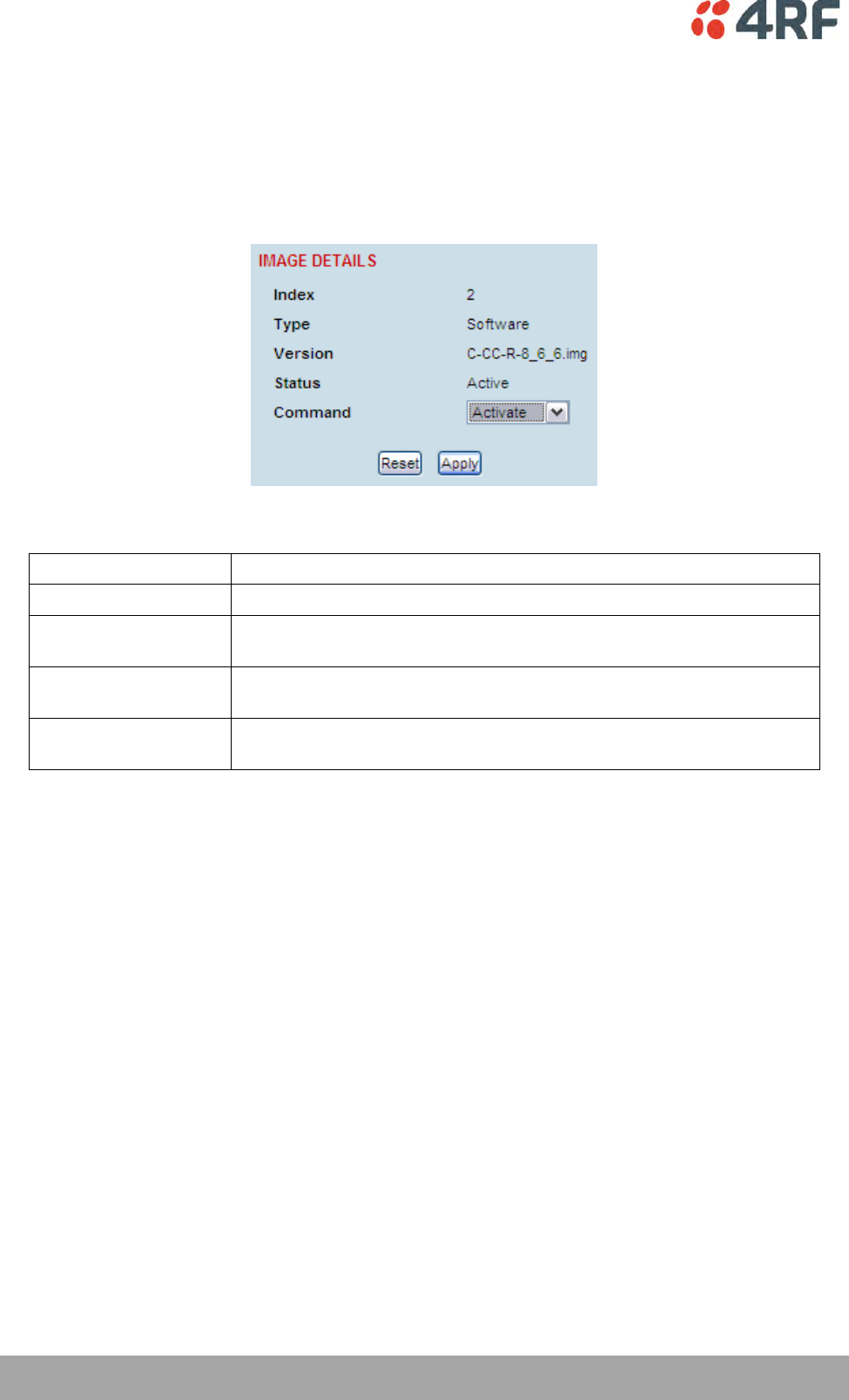
232 | Maintenance
Aprisa XE User Manual
Changing the Status of an Image File
To change the status of an image:
1. Select Link or Local or Remote > Maintenance > Image Table.
2. Select the image you wish to change and click Edit.
3. On the Image Details, select the status from the Command drop-down list and click Apply.
Status
Function
Active
The image is currently being used by the system.
Inactive
The image is not currently being used by the system and could be
deleted.
Selected
The image is not currently being used by the system but has been
activated and will become active following a terminal reboot.
Current (deselected)
The image is currently being used by the system but as another image
has been selected, it will become inactive following a terminal reboot.
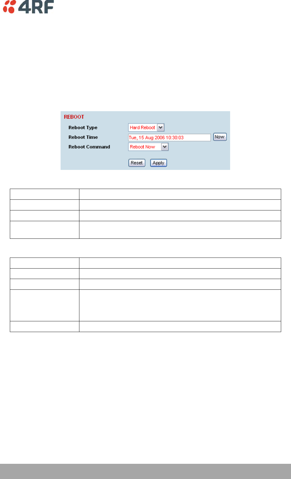
Maintenance | 233
Aprisa XE User Manual
Rebooting the Terminal
The local or remote terminals can be rebooted by SuperVisor.
You can specify a ‘Soft Reboot’ which reboots the terminal without affecting traffic or a ‘Hard Reboot’
which reboots the terminal (similar to power cycling the terminal).
You can specify an immediate reboot or setup a reboot to occur at a predetermined time.
To reboot the terminal:
1. Select Link or Local or Remote > Maintenance > Reboot.
2. Select the Reboot Type field:
Reboot Type
Function
None
Does nothing.
Soft Reboot
Reboots the software but does not affect customer traffic.
Hard Reboot
Reboots the entire terminal and affects customer traffic.
This reboot is similar cycling the power off and on.
3. Select the Reboot Command field:
Reboot Command
Function
None
Does nothing
Reboot Now
Execute the selected reboot now
Timed Reboot
Set the Reboot Time field to execute the selected reboot at a later date
and time.
This feature can be used to schedule the resulting traffic outage for a
time that has least customer impact.
Cancel Reboot
Cancel a timed reboot.
4. Click Apply to execute the reboot or Reset to restore the previous configuration.
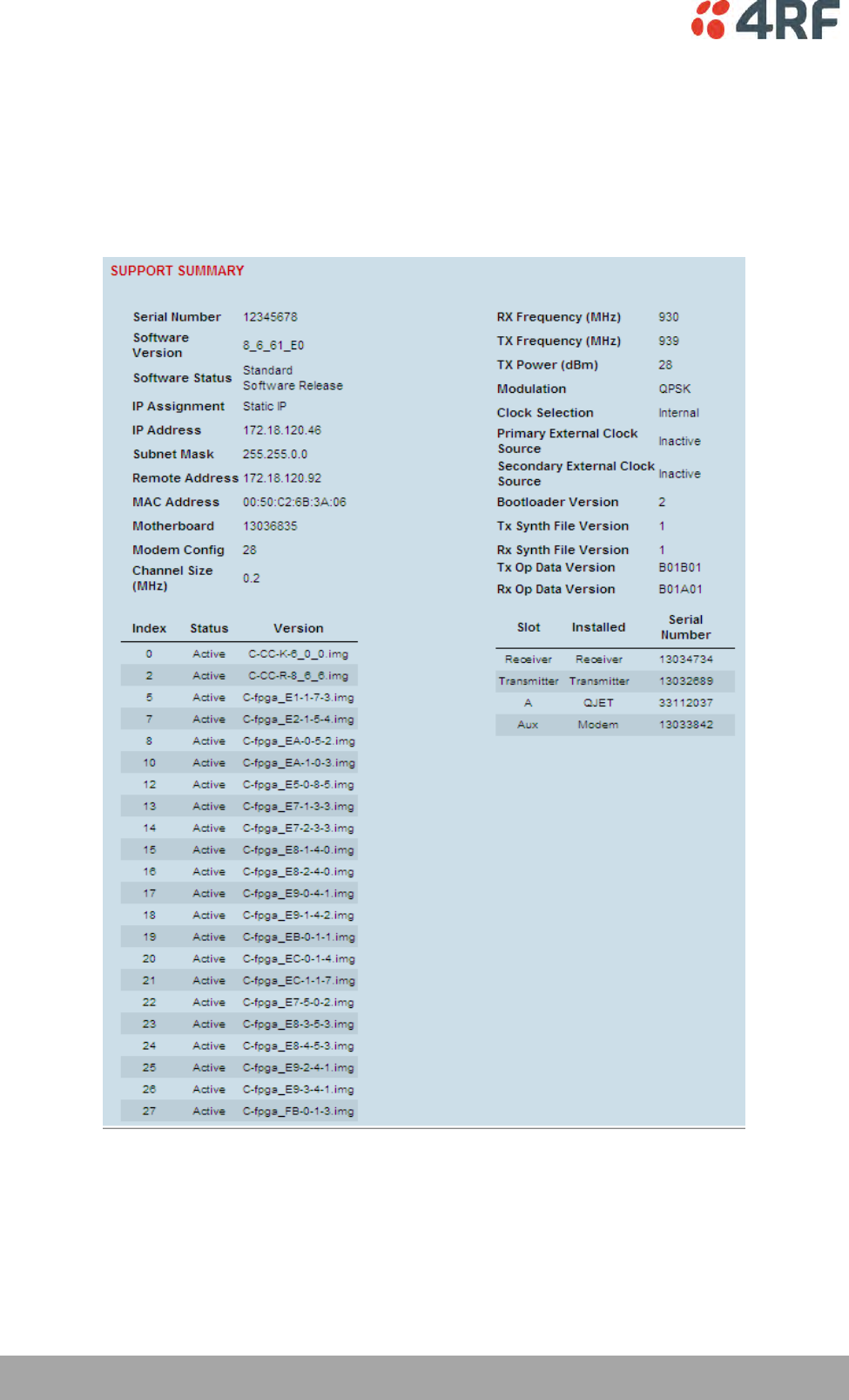
234 | Maintenance
Aprisa XE User Manual
Support Summary
The support summary page lists key information about the terminal, for example, serial numbers,
software version, frequencies and so on.
To view the support summary:
Select Link or Local or Remote > Maintenance > Support Summary.

Maintenance | 235
Aprisa XE User Manual
Installing Interface Cards
CAUTION: You must power down the terminal before removing or installing interface cards.
Interface cards are initially installed in the factory to the customers’ requirements however, during the
life of the product, additional interface cards may need to be installed.
Unless the terminals are protected (see ‘Protected terminals’ on page 197), installing new interface cards
involves a substantial interruption of traffic across the link. Staff performing this task must have the
appropriate level of education and experience; it should not be attempted by inexperienced personnel.
To install an interface card:
1. Switch off the power to the terminal.
2. Prepare the terminal for new interface cards (see ‘Preparing the Terminal for New Interface Cards’ on
page 236).
3. Install the interface card (see ‘Installing an Interface Card’ on page 238).
4. Power up the terminal.
5. Configure the slot (see ‘Configuring a Slot’ on page 240).
A slot can be configured before installing a new interface card, or after the interface card is installed
and the terminal power cycled.
6. Configure the cross connections. (see ‘Configuring the traffic cross connections’ on page 158)
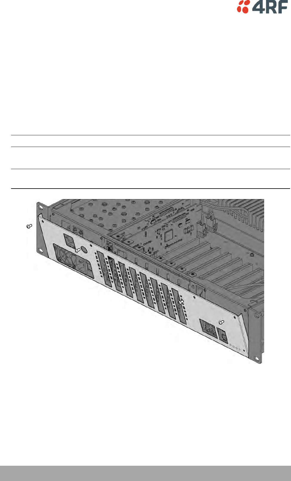
236 | Maintenance
Aprisa XE User Manual
Preparing the Terminal for New Interface Cards
To prepare the terminal for a new interface card:
1. Remove the terminal from service by first switching off the terminal power. For an AC powered
terminal, remove the AC power connector. For a DC powered terminal, switch off the DC circuit
breaker or supply fuse.
2. Remove all other cables from the terminal, marking their locations first, if necessary, to aid later
restoration. The safety earth connection must be the last cable removed.
3. Ensure you have unobstructed access to the top and front of the terminal. Remove the terminal from
the equipment rack, if required.
4. Remove the top cover of the terminal by removing two socket screws from the rear.
Note: The top cover slides back towards the rear of the chassis.
5. Remove the front fascia by removing the four front panel socket screws.
Note: The front fascia first hinges out to clear the antenna connector and earth stud, and is then
removed by unclipping from the chassis and sliding downwards. See illustration below.
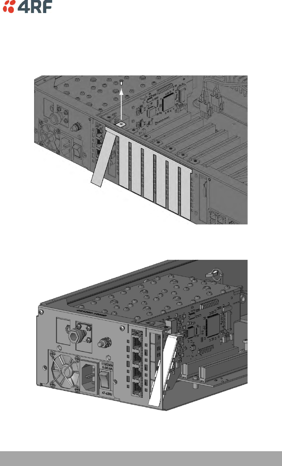
Maintenance | 237
Aprisa XE User Manual
6. Remove the card securing screw from the required interface slot.
7. There are two types of interface slot blanking plates, the seven tab break off and the single slot type
(newer type).
If the blanking plate is the seven tab break off, remove the slot blanking tab by folding the tab to and
fro until it breaks off.
If the blanking plate is the single slot type, unclip the blanking plate from behind the slot (assuming
that the card securing screw has already been removed).
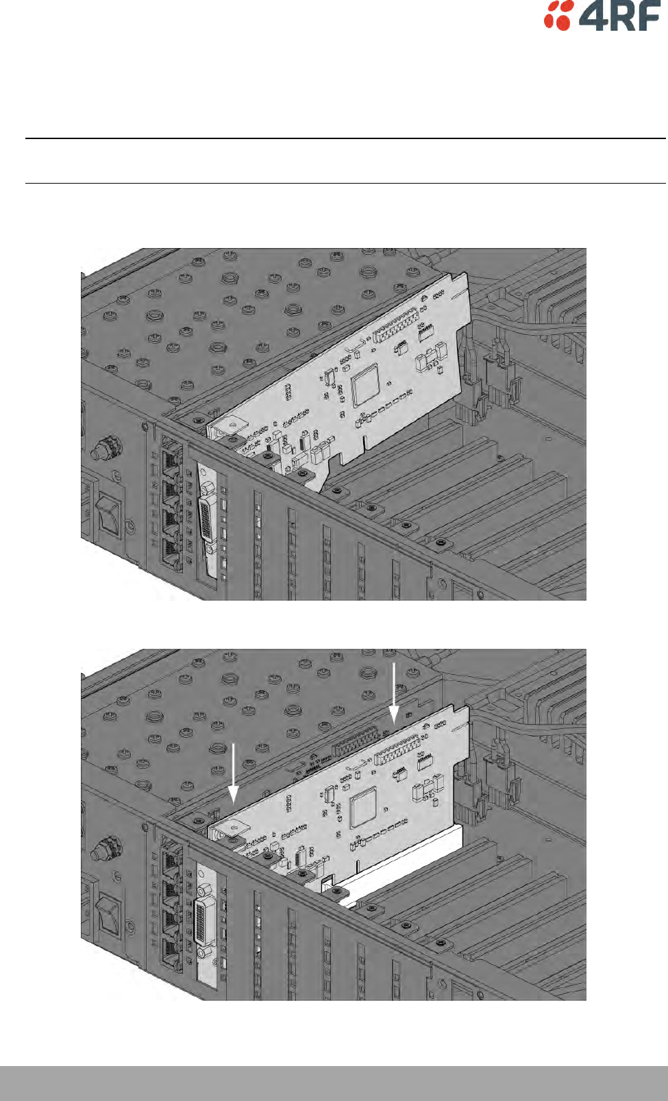
238 | Maintenance
Aprisa XE User Manual
Installing an Interface Card
To install an interface card:
1. Remove the interface card from its packaging and static-safe bag.
CAUTION: To avoid static damage to the terminal or the interface card being installed, use a static
discharge wristband or similar antistatic device.
2. Offer the interface card into the chassis at an angle until the front panel of the card engages in the
chassis.
3. Rotate the card in the chassis until it is level, and both parts of the card interface bus connector
engage with the socket. Push down evenly on the interface card to seat it into the socket.
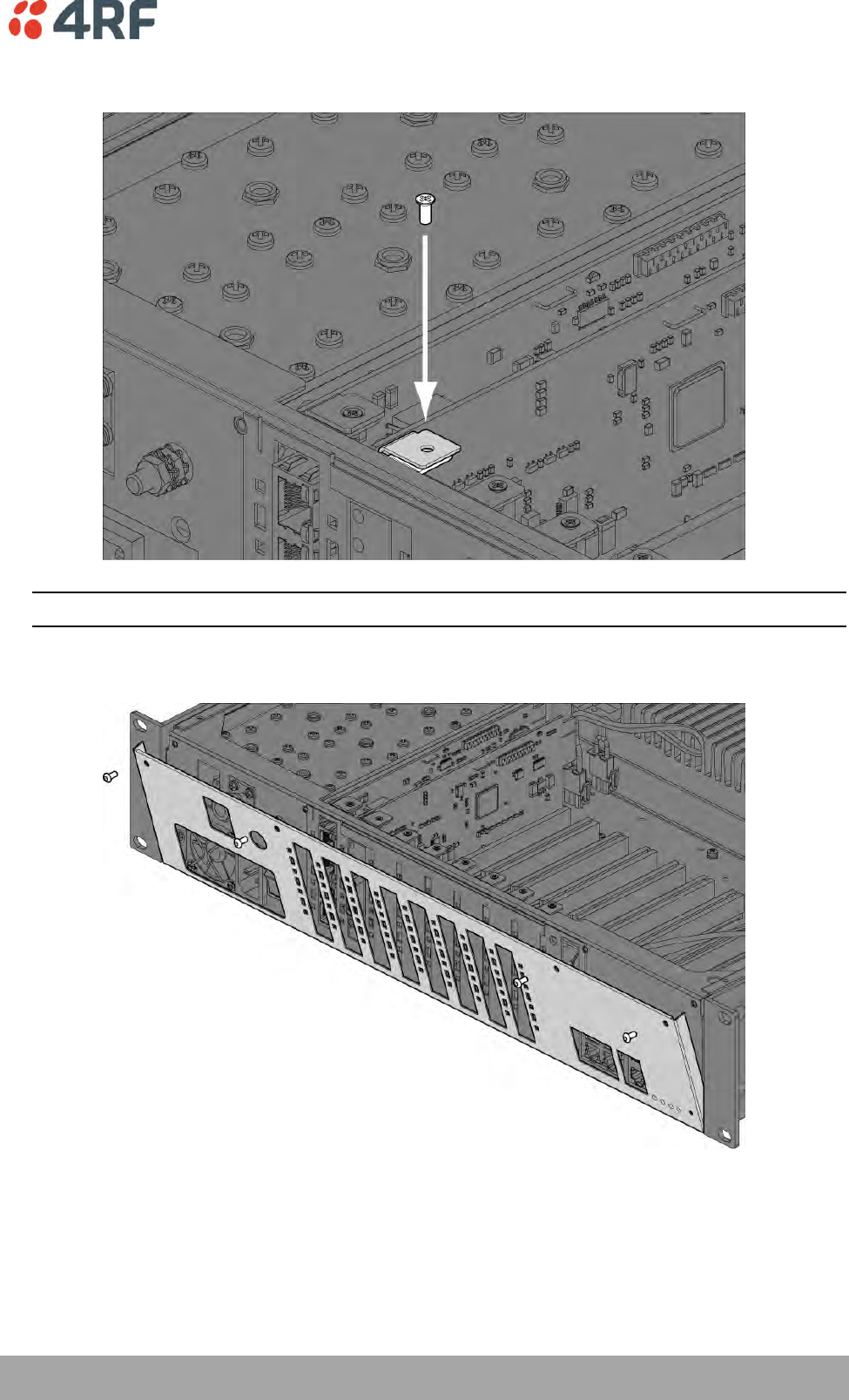
Maintenance | 239
Aprisa XE User Manual
4. Replace the card securing screw.
Note: Some interface cards may not have the bracket to accept the card securing screw.
5. Replace the fascia and top covers, restore all cables, and power up the terminal.
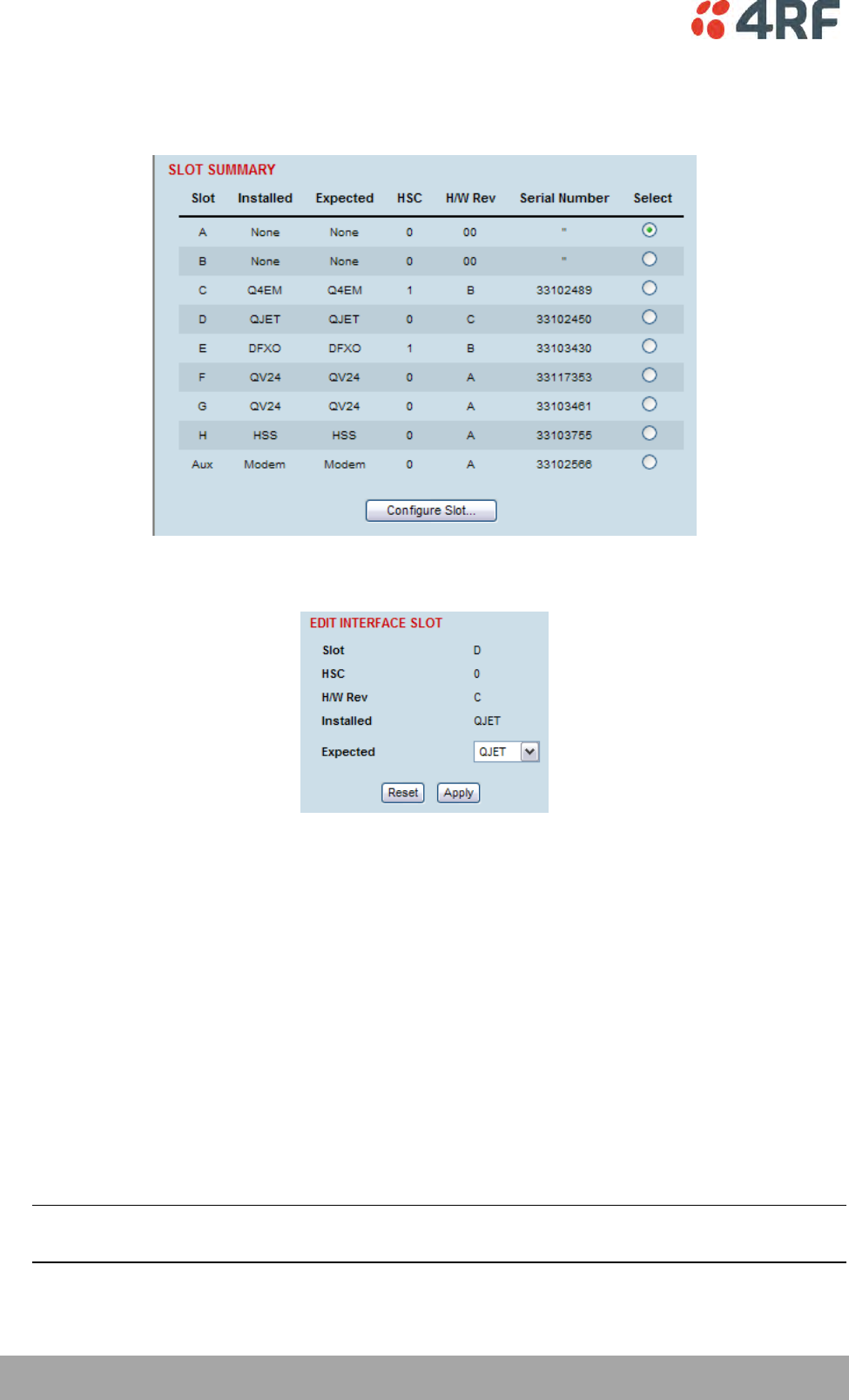
240 | Maintenance
Aprisa XE User Manual
Configuring a Slot
1. Select Link or Local or Remote > Interface > Slot Summary.
2. Select the required slot and click Configure Slot.
'Slot' shows the slot the interface card is plugged into in the terminal (A – H).
Details of the interface card currently installed in the slot are:
'HSC’ (hardware software compatibility) A number used by the system software to determine
which FPGA ‘firmware image file’ to use in the interface card installed.
'H/W Rev’ (hardware revision).
‘Installed’ field shows the actual interface card installed in the slot. If there is no interface card
installed in the slot, this field will show ‘none’.
‘Expected’ shows interface card type that had been previously installed. Interface cards can be setup
before they are installed in the terminal or after they are installed in the terminal.
3. To setup a new interface card in a slot, select the interface card type you want to fit (or has been
fitted) from the ‘Expected’ drop-down menu.
Note: The transmitter, receiver and modem are configured in other sections (see ‘Configuring the
terminal’ on page 69).
4. Click Apply to apply changes or Reset to restore the previous configuration.
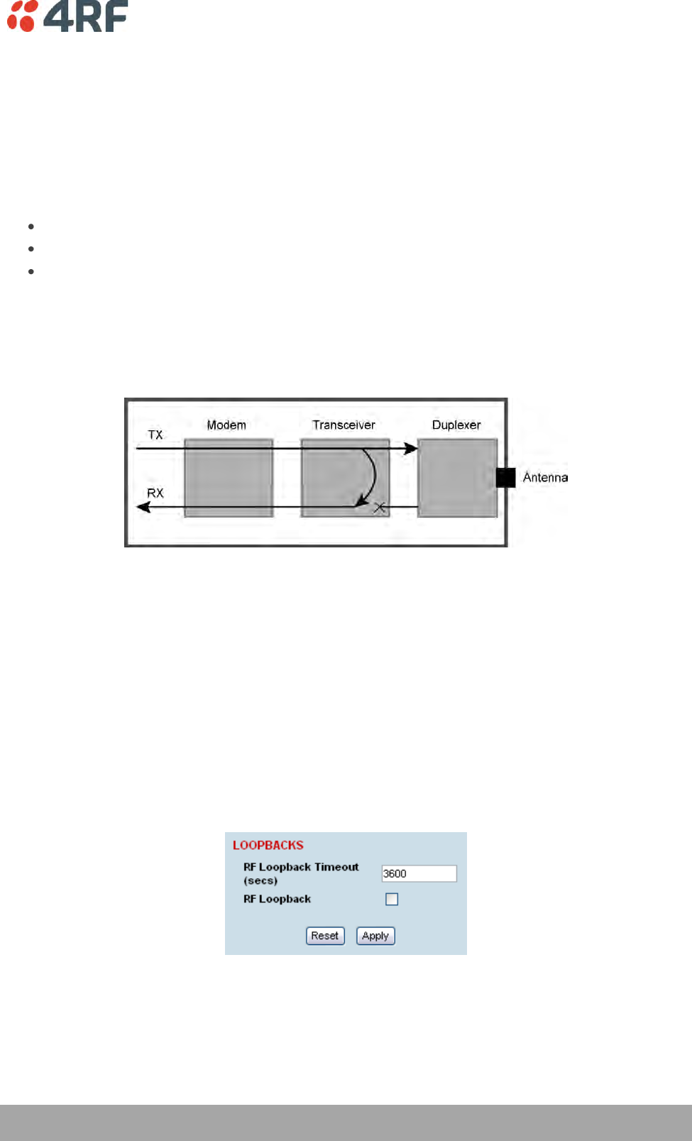
Troubleshooting | 241
Aprisa XE User Manual
14. Troubleshooting
Loopbacks
Loopbacks are used as a tool for testing or as part of the commissioning process and will affect customer
traffic across the link.
The terminal supports three types of loopbacks:
RF radio loopback
Interface loopbacks, set at the interface ports
Timeslot loopbacks
RF Radio Loopback
The RF radio loopback provides a loopback connection between the radio TX and radio RX. Each terminal
is looped back independently.
All traffic entering the transmit stage of the transceiver is transmitted on the RF link but is also looped
back to the receiver section of the transceiver. This loopback will affect all traffic through the terminal.
When the RF loopback is activated, both the radio RX and TX LEDs will flash.
An RF loopback will automatically deactivate after the period set (in seconds) in the RF Loopback Timeout
field. The default entry is 3600 seconds (60 minutes).
When an RF loopback is activated, the ethernet path is disabled to prevent ethernet loopbacks.
An RF loopback is deactivated if the terminal is rebooted.
To activate or deactivate the RF loopback:
Select Link or Local or Remote > Maintenance > Loopbacks.
To activate the RF loopback, tick the RF Loopback checkbox. Untick the checkbox to deactivate it.
Click Apply to apply changes or Reset to restore the previous configuration.
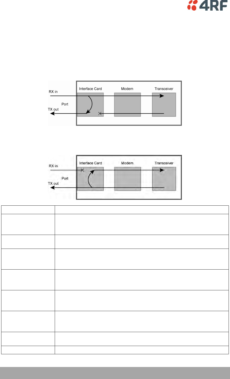
242 | Troubleshooting
Aprisa XE User Manual
Interface Loopbacks
The interface loopback provides a loopback connection for the customer-connected equipment.
These loopbacks are applied on a port-by-port basis and can only be enabled on active ports i.e. the port
has to be activated by assigning traffic to it by the Cross Connections application.
These are two types of interface loopbacks:
Line Facing – port traffic from the customer is transmitted over the RF link but is also looped back to the
customer
Radio Facing – traffic received from the RF link is passed to the customer port but is also looped back to
be transmitted over the RF link.
Loopback type
Description
QJET
(whole tributary)
The QJET interface port has both Line Facing and Radio Facing loopbacks (see
‘QJET Port Settings’ on page 102).
The interface card green LED flashes while the loopback is active.
QJET
(individual timeslot)
The Cross Connections application can loopback framed E1 / T1 timeslots (see
‘Timeslot Loopbacks’ on page 243).
Q4EM port
The Q4EM interface port has both Line Facing and Radio Facing loopbacks (see
‘Q4EM Port Settings’ on page 104).
The interface card yellow LED flashes while the loopback is active.
DFXO port
The DFXO interface Line Facing loopback loops back the port data to the
customer. This loopback is performed on the digital path of the codec.
The interface card yellow LED flashes while the loopback is active.
DFXS port
The DFXS interface Line Facing loopback loops back the port data to the
customer. This loopback is performed on the digital path of the codec.
The interface card yellow LED flashes while the loopback is active.
HSS port
The HSS interface Line Facing loopback loops back the port data to the
customer.
The interface card top green LED flashes while the loopback is active.
QV24 port
The QV24 interface Line Facing loopback will loop back the port data to the
customer.
Ethernet
No loopback possible.
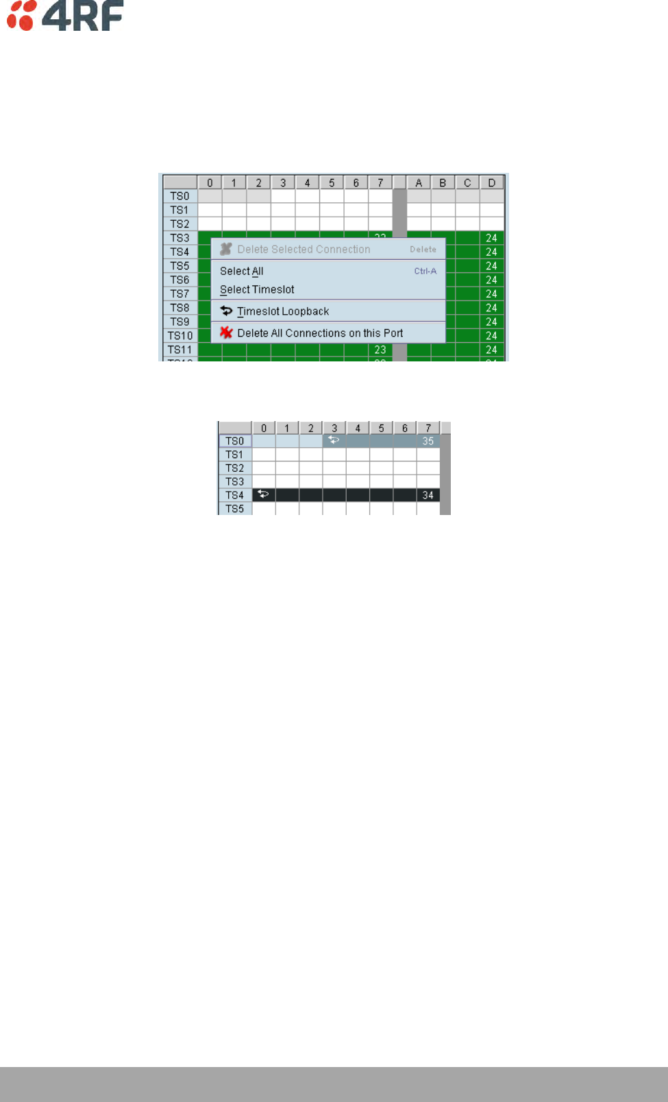
Troubleshooting | 243
Aprisa XE User Manual
Timeslot Loopbacks
You can loopback framed E1 / T1 timeslots in the Cross Connections application.
1. Open the Cross Connections application.
2. Right-click the timeslot you want to loop back.
3. Select Timeslot Loopback - the looped timeslot will display in black:
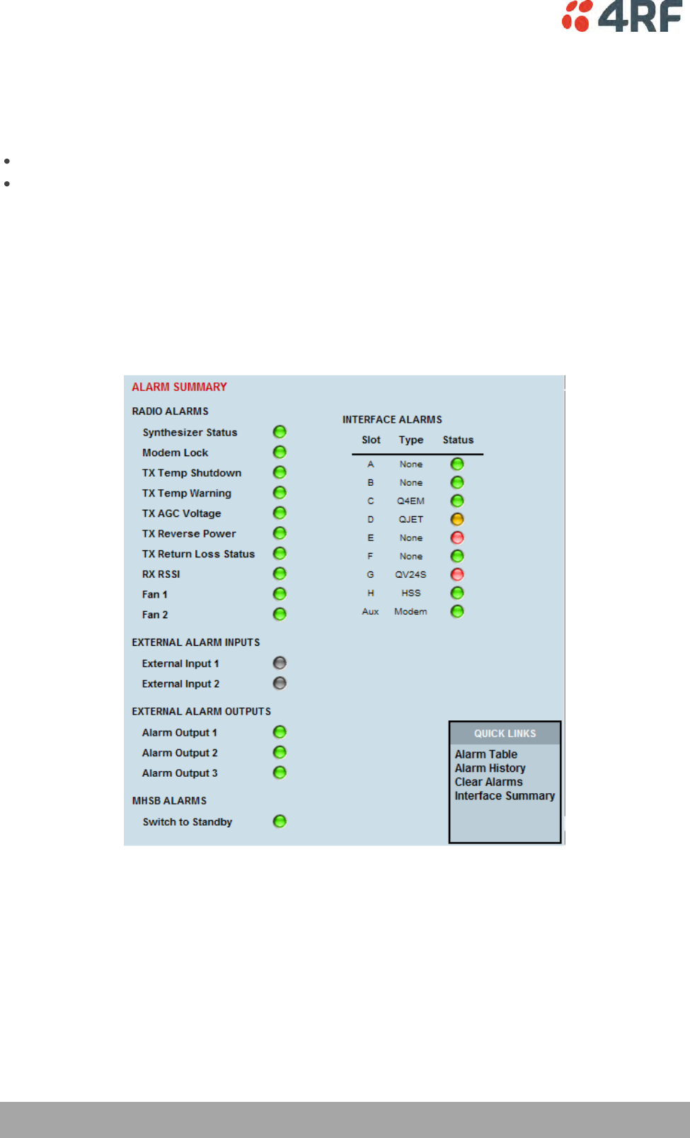
244 | Troubleshooting
Aprisa XE User Manual
Alarms
The LEDs (OK, RX, and TX) on the front panel illuminate either amber or red when there is a fault
condition:
Amber indicates a minor alarm that should not affect traffic across the link.
Red indicates a major alarm condition that could affect traffic across the link.
A major or minor alarm can be mapped to the external alarm outputs (see ‘Configuring the External Alarm
Outputs’ on page 83).
Diagnosing Alarms
To view the Alarm Summary and their current states:
Select Link or Local or Remote > Alarms > Summary.
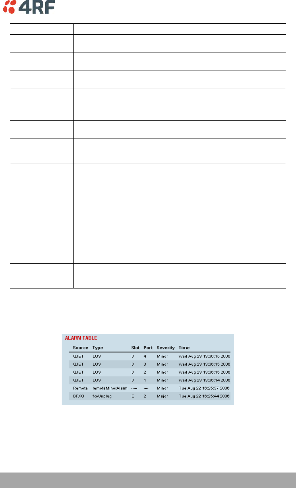
Troubleshooting | 245
Aprisa XE User Manual
Alarm
Explanation
Synthesizer Status
The selected transmit frequency is outside the tuning range of the
transmitter synthesizer
Modem Lock
The terminal modem is not synchronized with the modem at the other end
of the link
TX Temp Shutdown
The transmitter power amplifier temperature is greater than 75°C. The
transmitter has shut down to prevent damage.
TX Temp Warning
The transmitter power amplifier temperature is greater than 70°C. The
transmitter will continue to operate in this condition, but if the power
amplifier temperature increases above 75°C, a major alarm condition is
set and the transmitter will shut down to prevent further damage.
TX AGC Voltage
The transmitter power amplifier automatic gain control is out of limits for
normal operation
TX Reverse Power
There is excessive reflected power at the transmitter port of the terminal,
indicating a low return loss in the path between transmitter port and the
antenna.
TX Return Loss
Status
Indicates the difference between the transmitted power and the amount
of power being reflected back into the terminal. The alarm will trigger
when there is too much reflected power from the antenna that will
degrade link performance.
RX RSSI
The RX RSSI alarm threshold is determined by the RSSI Thresholds for each
of the modulation types (see ‘Setting the RSSI Alarm Threshold’ on page
80)
Fan 1
The internal cooling fan 1 is not operating
Fan 2
The internal cooling fan 2 is not operating
External Input 1 -2
Indicates an active alarm state on the the external alarm input
Alarm Output 1 - 4
Indicates an active alarm state on the the external alarm output
MHSB Switch
Indicates that the MHSB has switched over. The MHSB alarm is only shown
if MHSB mode is enabled (see ‘Configuring the Terminals for MHSB’ on
page 188).
To view detailed alarm information:
Select Link or Local or Remote > Alarms > Alarm Table
The Alarm Table shows the source of the alarm and the type, the slot (and port, if applicable) where the
alarm originated, the severity and the date and time the alarm occurred.
To further diagnose the cause of the alarm (see ‘Identifying Causes of Alarms’ on page 250, and ‘Alarm
Types’ on page 275).
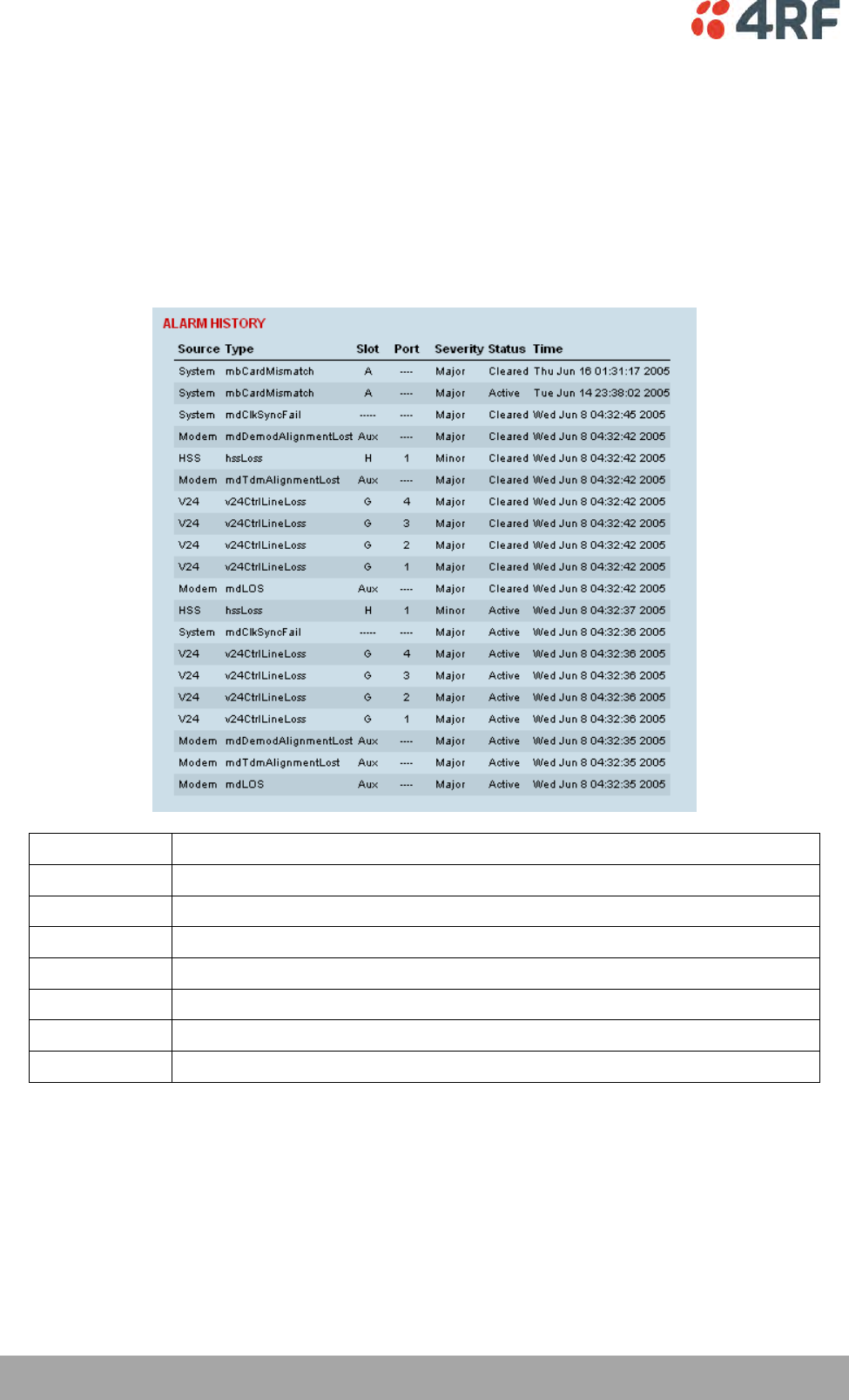
246 | Troubleshooting
Aprisa XE User Manual
Viewing the Alarm History
The alarm history page shows the historical alarm activity for up to 50 alarms. This page refreshes every
30 seconds.
The alarm history for up to 100 alarms can be seen using SNMP (see ‘Configuring SNMP’ on page 85).
To view the alarm history:
Select Link or Local or Remote > Alarms > Alarm History.
Field
Explanation
Source
The component within the terminal that generated the alarm
Type
The type of alarm (see ‘Alarm types and sources’ on page 275)
Slot
The slot where the alarm originated, if applicable
Port
The port where the alarm originated, if applicable
Severity
Whether the alarm was a major or minor alarm
Status
Whether the alarm is active or cleared
Time
The date and time when the alarm occurred
To clear the alarm history:
Select Local or Remote > Alarms > Clear History
This function clears all the alarm history including the 600 alarm rolling buffer (see ‘Saving the Alarm
History’ on page 247).
Troubleshooting | 247
Aprisa XE User Manual
Saving the Alarm History
The last 1500 alarms are stored in a rolling buffer which can be saved as a *.csv file.
To save the alarm history:
Select Local > Alarms > Save History
A File Download dialog box opens.
Click on Save to save the *.csv file to a folder or click on Open to open the file in the SuperVisor page.
Example of file:
Source Type Slot Port Severity Status Time
SNR
(dB)
RSSI
(dBm)
Modem mdLOS Aux - Major Active Tue Jan 22 12:45:54 2008 0 0
Modem mdTdmAlignmentLost Aux - Major Active Tue Jan 22 12:45:54 2008 0 0
Modem mdDemodAlignmentLost Aux - Major Active Tue Jan 22 12:45:54 2008 0 0
QV24 v24CtrlLineLoss G 1 Major Active Tue Jan 22 12:45:55 2008 0 0
QV24 v24CtrlLineLoss G 2 Major Active Tue Jan 22 12:45:55 2008 0 0
QV24 v24CtrlLineLoss G 3 Major Active Tue Jan 22 12:45:55 2008 0 0
System mdClkSyncFail ---- - Major Active Tue Jan 22 12:45:57 2008 0 0
Modem mdLOS Aux - Major Cleared Tue Jan 22 12:45:57 2008 0 0
Modem mdTdmAlignmentLost Aux - Major Cleared Tue Jan 22 12:45:57 2008 0 0
Modem mdDemodAlignmentLost Aux - Major Cleared Tue Jan 22 12:45:57 2008 0 0
Transmitter txADCChZeroLo Transmitter - Minor Active Tue Jan 22 12:45:57 2008 0 0
Transmitter txADCChZeroLo Transmitter - Minor Cleared Tue Jan 22 12:45:58 2008 0 0
System mdClkSyncFail ---- - Major Cleared Tue Jan 22 12:45:58 2008 0 0
QV24 v24CtrlLineLoss G 1 Major Cleared Tue Jan 22 12:45:59 2008 35.28 0
QV24 v24CtrlLineLoss G 2 Major Cleared Tue Jan 22 12:45:59 2008 35.29 0
QV24 v24CtrlLineLoss G 3 Major Cleared Tue Jan 22 12:45:59 2008 35.26 0
HSS hssLoss H 1 Minor Active Tue Jan 22 13:51:17 2008 35.28 -52.8
HSS hssLoss H 1 Minor Cleared Tue Jan 22 13:51:17 2008 35.27 -52.8
QJET LOS D 1 Minor Active Tue Jan 22 13:51:35 2008 35.29 -52.8
Note: Windows security settings can prevent the download of files. In this case, click on the windows
security message and select the SuperVisor menu option again (Alarms > Save History).
To save the alarm history from the Remote terminal, login to the Remote terminal and Select Local >
Alarms > Save History.
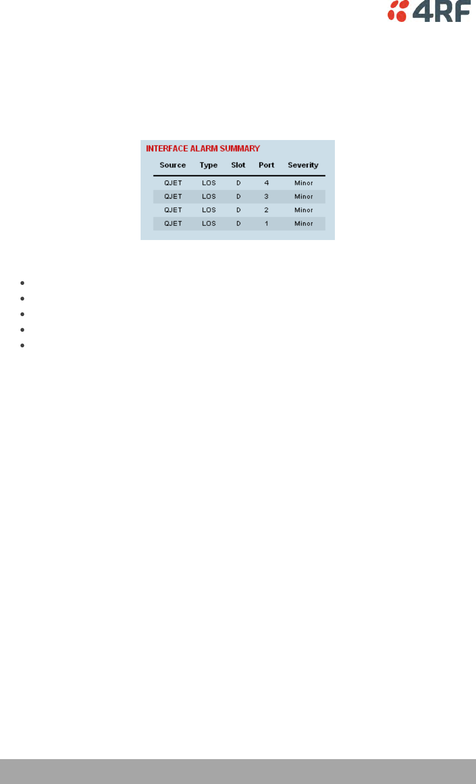
248 | Troubleshooting
Aprisa XE User Manual
Viewing Interface Alarms
To view the alarms for a particular interface:
1. Select Link or Local or Remote > Interface > Interface Summary.
2. Select the desired interface card slot from the Interface Summary and click Alarms.
This opens a page as shown below with a summary of the alarms on the interface card:
The following fields are displayed:
Source: The type of interface card that generated the alarm
Type: The type of interface alarm
Slot: The slot of the interface card that generated the interface alarm
Port: The port that generated the interface alarm
Severity: Whether the interface alarm was major or minor
3. Return to the Interface Summary page by either selecting Options > Interface Summary or clicking
Back in the browser window.
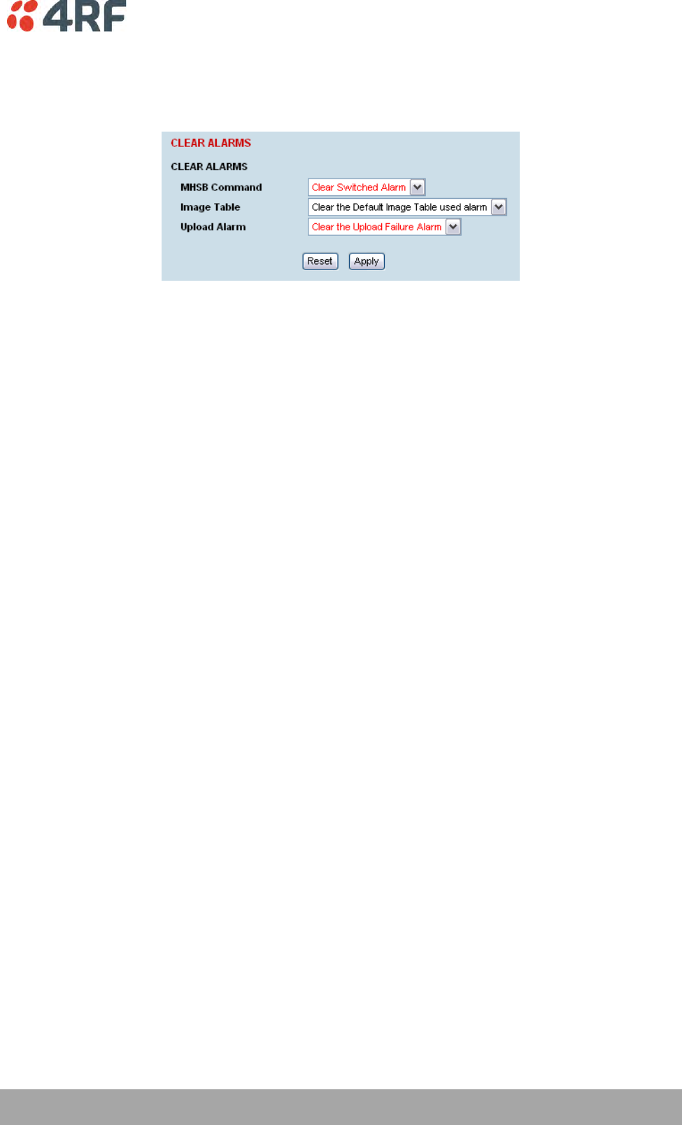
Troubleshooting | 249
Aprisa XE User Manual
Clearing Alarms
Select Link or Local or Remote > Alarms > Clear Alarms
MHSB Command
If a MHSB switchover event occurs, the OK LED on the front panel changes to amber.
To clear the MHSB switchover alarm:
Select ‘Clear Switched Alarm’ from the MHSB Command drop-down list and click on Apply.
Image Table Alarm
An image table alarm occurs if a problem occurred during the boot process which may have left the image
table in an inconsistent state.
To clear the image table alarm:
The default image table alarm: this indicates that the image table has been rebuilt from defaults. This
can indicate that an incorrect build of software is running on the terminal.
Select ‘Clear the Default Image Table used alarm’ from the Image Table drop-down list and click on Apply.
In addition to clearing the image table alarm, you should verify that the active images in the image table
are correct for the software release.
Upload Alarm
An Upload Alarm occurs if the TFTP Upgrade process fails. This can indicate that the upgrade process
cannot find the TFTP server or cannot find the software version number entered.
To clear the upload alarm alarm:
Select ‘Clear the Upload Failure Alarm’ from the Upload Alarm drop-down list and click on Apply.
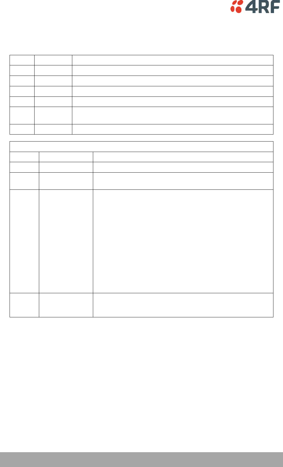
250 | Troubleshooting
Aprisa XE User Manual
Identifying Causes of Alarms
The following are possible causes of an alarm.
LED
Colour
Possible causes
OK
Amber
A minor system alarm is set
Red
A major system alarm is set
RX
Amber
Low RSSI or AGC limits have been exceeded
Red
Receiver power supply or synthesizer failure
TX
Amber
AGC, transmitter temperature, forward power or reverse power limits
have been exceeded
Red
Transmit power supply or synthesizer failure
OK LED
Colour
Alarm condition
Suggested action
Amber
Fan failure
Check that the fans are not blocked and can spin freely.
Amber
Interface card
mismatch
Using SuperVisor, check that the expected interface card and the
fitted interface card are the same.
Red
Modem lock
A modem lock alarm is generally seen when other conditions such
as low RSSI are present. If there are no other alarms indicated,
check the following:
The terminal clocking is set up correctly.
Both terminals are using the same modulation.
Both terminals are using the same version of software.
External RF Interference from equipment operating in adjacent
channels.
Check the constellation pattern for evidence of disturbances in
the RF path.
Compare RSSI with the expected values from the original path
engineering calculation. Investigate any large differences.
If the fault persists, contact your local representative.
Red
Interface alarms
Check that the E1 or Ethernet interface cables are fitted
correctly and the equipment they are connected to is functioning
correctly.

Troubleshooting | 251
Aprisa XE User Manual
RX LED
Colour
Alarm condition
Suggested action
Amber
Low RSSI
Check that all antenna and feeder cables are firmly connected
and not damaged or kinked
Check there is no damage to the antenna
Check the TX power and alarm status of the remote terminal
Amber
Receiver AGC
Contact your local 4RF representative
Red
Receiver power
supply
Contact your local 4RF representative
TX LED
Colour
Alarm condition
Suggested action
Amber
Reverse power
Check that all antenna and feeder cables are firmly connected
and not damaged or kinked
Check there is no damage to the antenna
Check that the Receiver and Transmitter ports are correctly
connected to the High and Low ports of the duplexer
Red
Transmitter
temperature
Check operation of cooling fan or fans
Ensure the air grills on the sides of the terminal are clear
Ensure the ambient air temperature around the equipment is
less than 50˚C

252 | Troubleshooting
Aprisa XE User Manual
E1 / T1 Alarm Conditions
The QJET interface yellow LED indicates:
Loss of signal (LOS)
A loss of signal alarm occurs when there is no valid G.703 signal at the E1 / T1 interface RX input from
the downstream system.
This alarm masks the LOF and AIS received alarms.
Loss Of Frame alignment (LOF)
A loss of frame alignment alarm occurs when the E1 / T1 interface RX input receives a valid G.703
signal (code and frequency) but does not receive a valid G.704 signal i.e. no frame alignment word,
from the downstream system (in framed E1 / T1 modes only) (red alarm in framed T1 modes).
This alarm masks the AIS received alarm.
Alarm Indication Signal (AIS)
An AIS received alarm occurs when AIS is received from the downstream system.
An E1 / T1 interface will output AIS to the downstream system if the normal upstream traffic signal is
not available e.g. loss of modem synchronization, loss of RF signal across the link (blue alarm in
framed T1 modes).
Remote Alarm Indicator (RAI)
A remote alarm indicator occurs when RAI is received from the downstream system when it has an
active LOS or LOF alarm (TS0 NFAS bit 3 in framed E1 modes and yellow alarm in framed T1 modes).
TS16 Loss of signal (TS16LOS)
A TS16 loss of signal alarm occurs when there is no valid TS16 signal at the E1 interface RX input from
the downstream system (in E1 PCM 30 modes only).
TS16 Remote Multi-frame Alarm Indicator (RMAI)
A remote multiframe alarm indicator occurs when RMAI is received from the downstream system when
it has an active TS16LOS alarm (TS16 F0 bit 6 in E1 PCM 30 modes only).
TS16 Alarm Indication Signal (TS16AIS)
A TS16 Alarm Indication Signal alarm occurs when AIS is received from the downstream system in TS16.
An E1 interface will output the TS16 AIS signal to the downstream system if the normal TS16 multi-
frame signal is not available (in E1 PCM 30 modes only).
The QJET interface green LED indicates:
The QJET interface green LED flashes when the E1 / T1 port loopback is active.
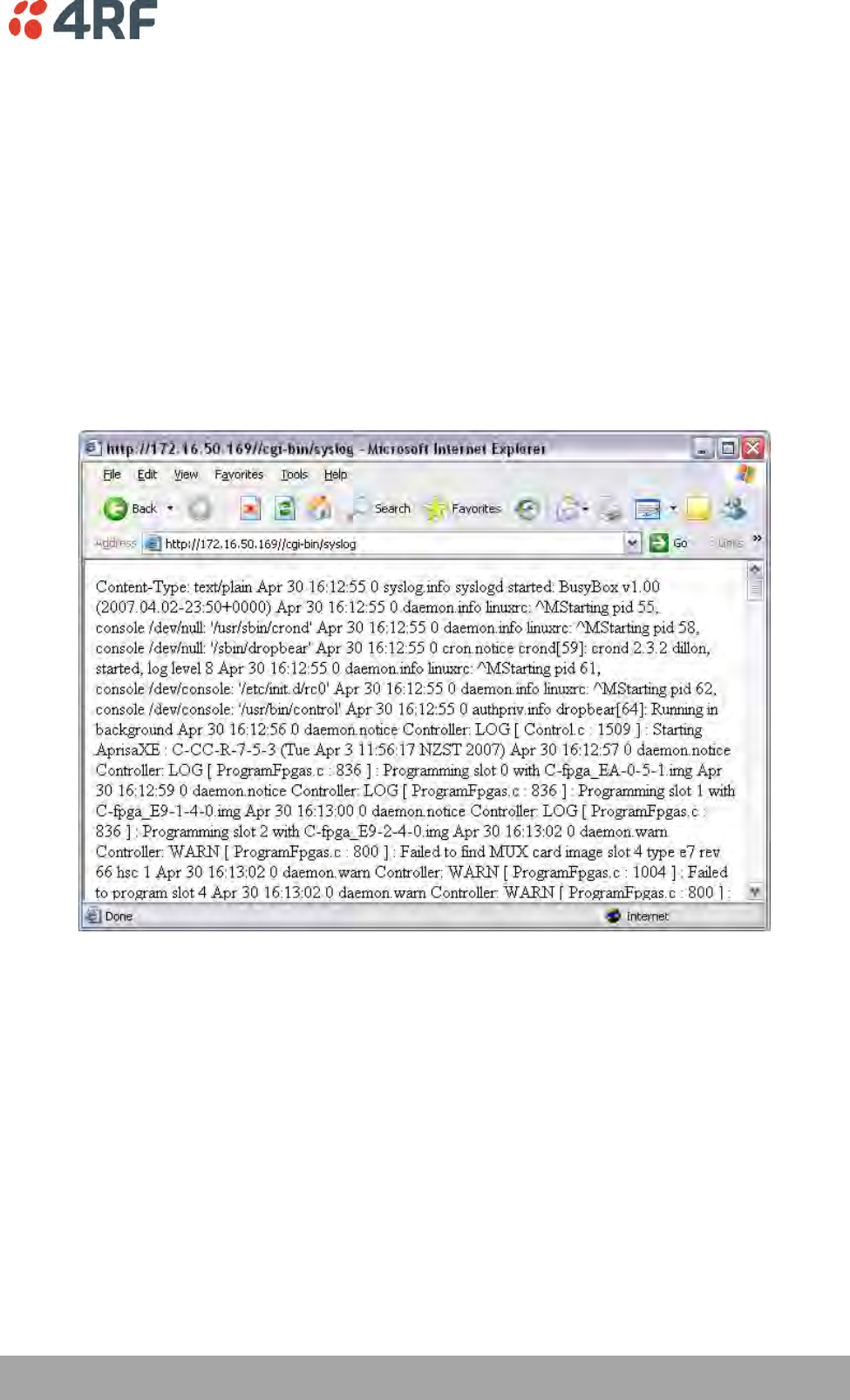
Troubleshooting | 253
Aprisa XE User Manual
System Log
SuperVisor automatically keeps a log, known as 'syslog', which captures all alarms, errors and events for
each terminal.
You can specify that the ‘syslog’ is saved to a particular file (see ‘Setting up for Remote Logging’ on page
255). You can then email this file to customer service, if requested, to enable them to fault-find more
accurately.
Checking the Syslog
To view the Syslog:
1. Select Local > Performance > Logging > Syslog.
This opens a new window:
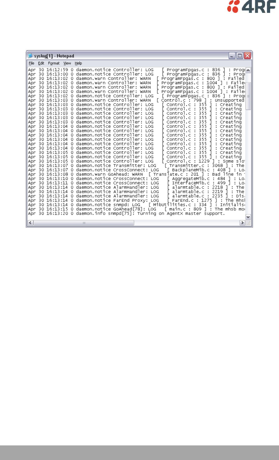
254 | Troubleshooting
Aprisa XE User Manual
2. The system log is quite hard to decipher in Internet Explorer. If you're using Internet Explorer, select
View > Source, which opens the file in a more legible layout in Notepad. Save or print this file, as
required.
3. If you want to save the system log, you can save it from within Notepad (or Internet Explorer). Select
File > Save As. Navigate to where you want to save the file. Enter a meaningful filename and select
'Text File' from the Save As Type drop-down list. Click Save.
You can specify that this file is automatically saved to a computer (see ‘Setting up for Remote Logging’ on
page 255).
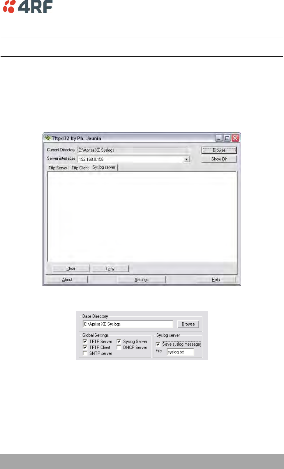
Troubleshooting | 255
Aprisa XE User Manual
Setting up for Remote Logging
Note: When setting up to save the system log to a specific computer, be aware that the file is constantly
updated and may get quite large quite quickly.
To set up a terminal for remote logging:
1. Copy the TFTP server application (tftpd32.exe, which is located in the TFTPD directory) from the
terminal product CD into a suitable directory on the PC (for example, C:\Program Files\TFTP Server).
2. Create another directory where you want the system logs to be saved for example;
C:\Aprisa XE Syslog
3. Double-click tftpd32.exe.
4. Click Settings and make sure that both ‘Syslog Server’ and ‘Save syslog message’ boxes are ticked.
5. Click Browse and select a directory where you want the Syslog file to be saved (created in step 2).
6. Click OK to close the Settings dialog box.
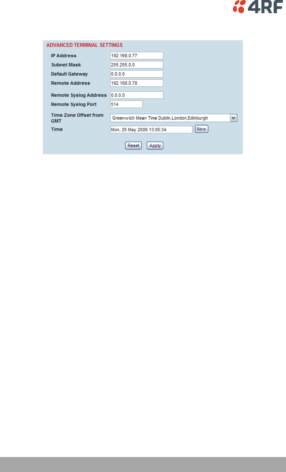
256 | Troubleshooting
Aprisa XE User Manual
7. In SuperVisor, select Link or Link or Local or Remote > Terminal > Advanced.
8. In the Remote Syslog Address field, enter the IP address of the PC on which the Syslog server is
running.
9. In the Remote Syslog Port field, enter 514.
10. Reboot the terminal (Link or Local or Remote > Maintenance > Reboot).
11. Open the directory where the system logs are being saved to. You should see a file called syslog.txt.
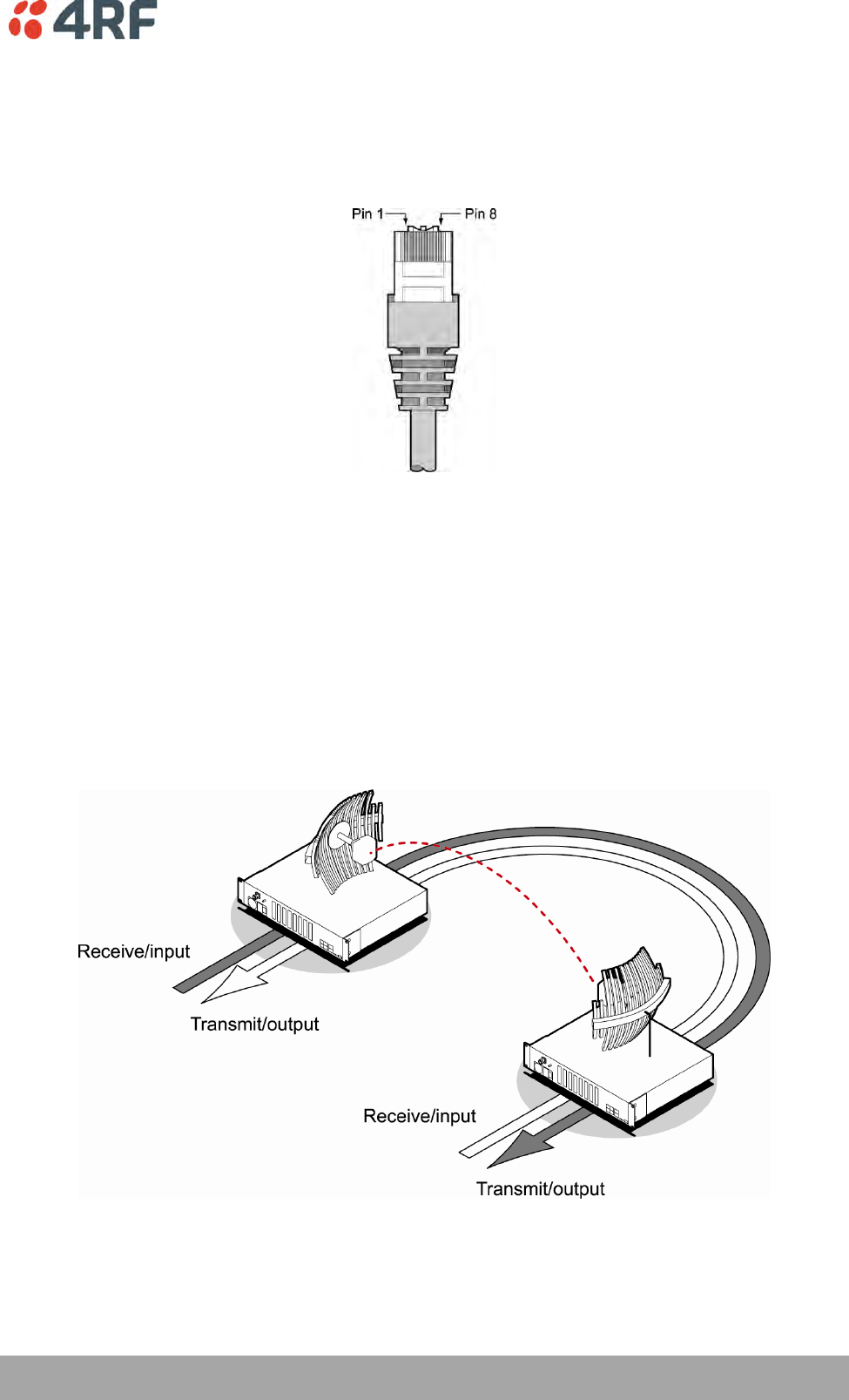
Interface Connections | 257
Aprisa XE User Manual
15. Interface Connections
RJ-45 Connector Pin Assignments
RJ-45 pin numbering
Interface Traffic Direction
All interface traffic directions and labels used in this manual refer to the direction relative to the
terminal. Refer to the diagram below.
The traffic direction describes the transmit / receive paths and the direction of handshaking and clocking
signals, depending on the interface.
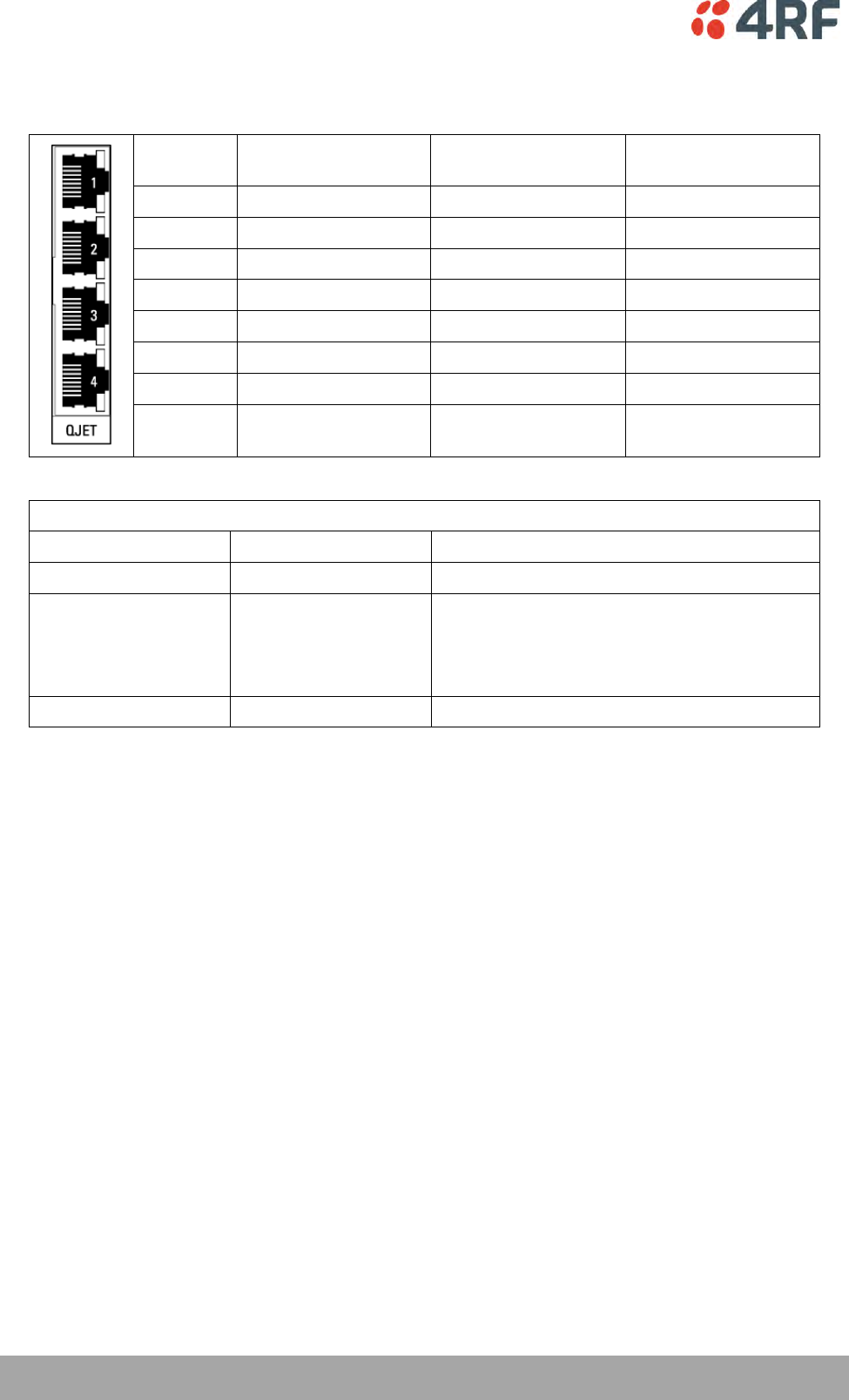
258 | Interface Connections
Aprisa XE User Manual
QJET Interface Connections
Pin
number
Pin function
Direction
TIA-568A wire colour
1
Transmit
Output
Green/white
2
Transmit
Output
Green
3
Not used
Orange/white
4
Receive
Input
Blue
5
Receive
Input
Blue/white
6
Not used
Orange
7
Not used
Brown/white
8
Not used
Brown
RJ-45 connector LED indicators
LED
Status
Explanation
Green
On
Normal operation
Yellow
On
Loss of signal (LOS) or
Alarm Indication Signal (AIS) or
Loss Of Frame alignment (LOF) in Framed
modes
Green
Flashing
Port in loopback
The standard QJET interface is 120 ohm balanced.
External Balun transformers can be used to provide a 75 ohm unbalanced interface.
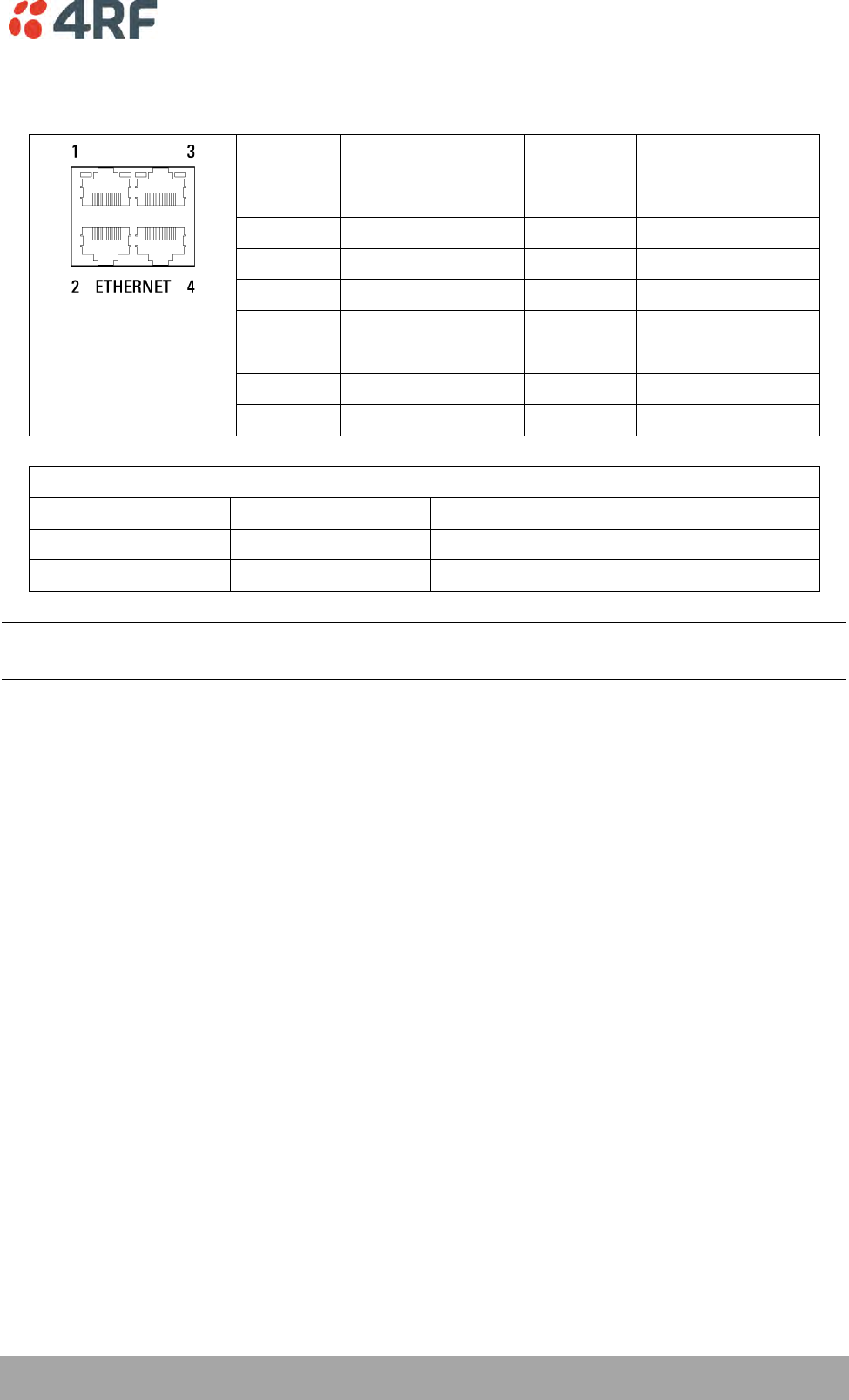
Interface Connections | 259
Aprisa XE User Manual
Ethernet Interface Connections
Pin
number
Pin function
Direction
TIA-568A wire
colour
1
Transmit
Output
Green/white
2
Transmit
Output
Green
3
Receive
Input
Orange/white
4
Not used
Blue
5
Not used
Blue/white
6
Receive
Input
Orange
7
Not used
Brown/white
8
Not used
Brown
RJ-45 connector LED indicators
LED
Status
Explanation
Green
On
Ethernet signal received
Green
Flashing
Indicates data traffic present on the interface
Note: Do not connect Power over Ethernet (PoE) connections to the Aprisa XE Ethernet ports as this will
damage the port.
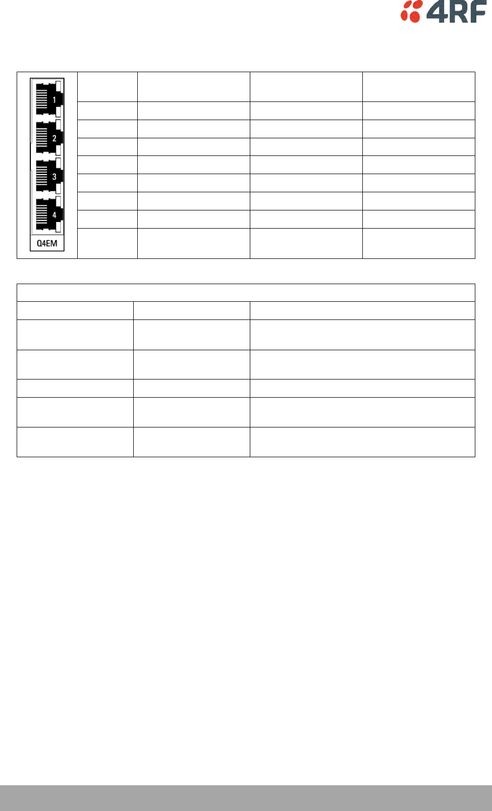
260 | Interface Connections
Aprisa XE User Manual
Q4EM Interface Connections
Pin
number
Pin function
Direction
TIA-568A wire
colour
1
M
Input
Green/white
2
M1
Input
Green
3
Receive (Ra/R)
Input
Orange/white
4
Transmit (Tb/R1)
Output
Blue
5
Transmit (Ta/T1)
Output
Blue/white
6
Receive (Rb/T)
Input
Orange
7
E
Output
Brown/white
8
E1
Output
Brown
RJ-45 connector LED indicators
LED
Status
Explanation
Green
Off
No external source applied to M wire (no M
wire current flowing)
Green
On
External source applied to M wire (M wire
current flowing)
Green
Flashing
The interface loopback is active
Yellow
Off
E wire relay contact open (no current in
external device)
Yellow
On
E wire relay contact closed (current flowing
in external device)
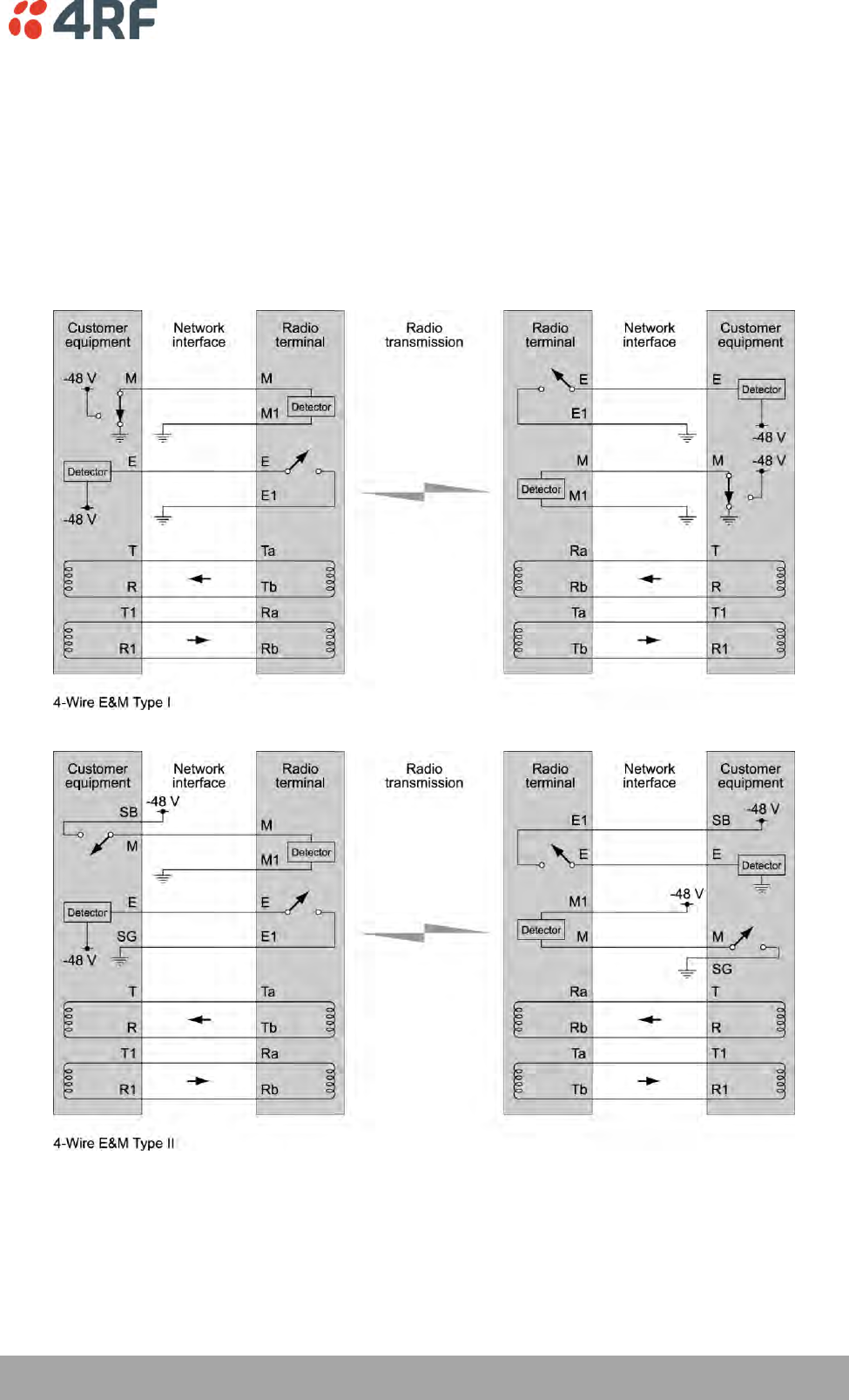
Interface Connections | 261
Aprisa XE User Manual
E&M Signalling Types
The Q4EM E&M signalling leads are optically isolated, bi-directional lines which can be externally
referenced to meet any of the EIA-464 connection types I, II,IV or V (as shown below).
The M1 lead associated with the M wire detector can be externally referenced to earth or battery as
required.
The E1 lead associated with the E wire output can be externally referenced to earth or battery as
required.
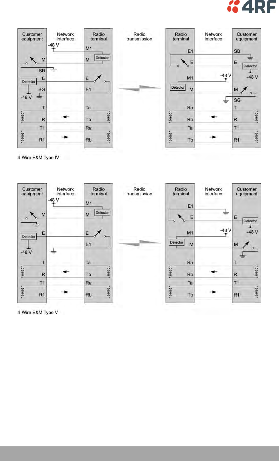
262 | Interface Connections
Aprisa XE User Manual
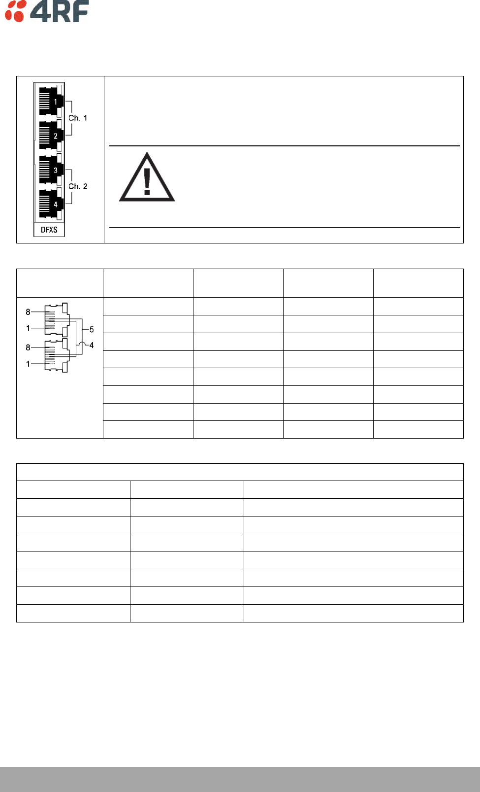
Interface Connections | 263
Aprisa XE User Manual
DFXS Interface Connections
The subscriber interface connects the terminal to the customer's 2 wire
telephone via a 2 wire line.
Each 2 wire channel has two access points: one connects to a customer; the
other is a local test port.
CAUTION:
If there is a power failure at either terminal, any telephone
connected at the DFXS will not operate.
Please ensure that a separate telephone that is not
dependent on local power is available for use in an
emergency.
RJ-45
Pin number
Pin function
Direction
TIA-568A wire
colour
1
Not used
Green/white
2
Not used
Green
3
Not used
Orange/white
4
Ring
Bi-directional
Blue
5
Tip
Bi-directional
Blue/white
6
Not used
Orange
7
Not used
Brown/white
8
Not used
Brown
RJ-45 connector LED indicators
LED
Status
Explanation
Green
Off
Interface operational but not in service
Green
On
Normal operation
Green
Flashing
Cadenced ringing on line
Yellow
Off
No interface alarm
Yellow
On
Interface alarm
Yellow
Flashing
The interface loopback is active
Both LEDs
Flashing
Loss of CAS signals
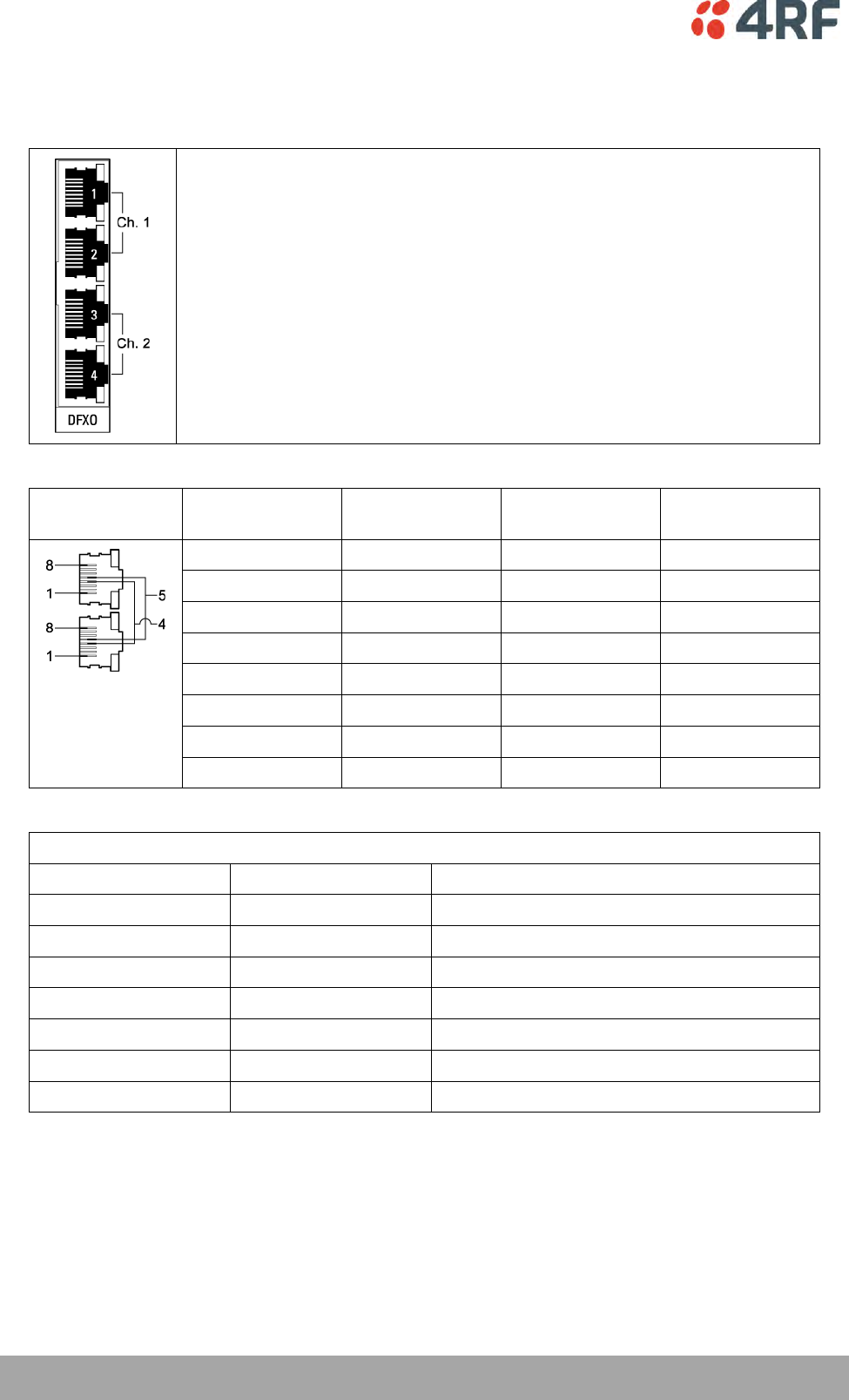
264 | Interface Connections
Aprisa XE User Manual
DFXO Interface Connections
The DFXO interface connects the terminal to the telephone network via a 2
wire line.
Each DFXO channel has two access points: one connects to a customer; the
other is a local test port.
RJ-45
Pin number
Pin function
Direction
TIA-568A wire
colour
1
Not used
Green/white
2
Not used
Green
3
Not used
Orange/white
4
Ring
Bi-directional
Blue
5
Tip
Bi-directional
Blue/white
6
Not used
Orange
7
Not used
Brown/white
8
Not used
Brown
RJ-45 connector LED indicators
LED
Status
Explanation
Green
Off
Interface operational but not in service
Green
On
Normal operation
Green
Flashing
Cadenced ringing on line
Yellow
Off
No interface alarm
Yellow
On
Interface alarm
Yellow
Flashing
The interface loopback is active
Both LEDs
Flashing
Loss of CAS signals
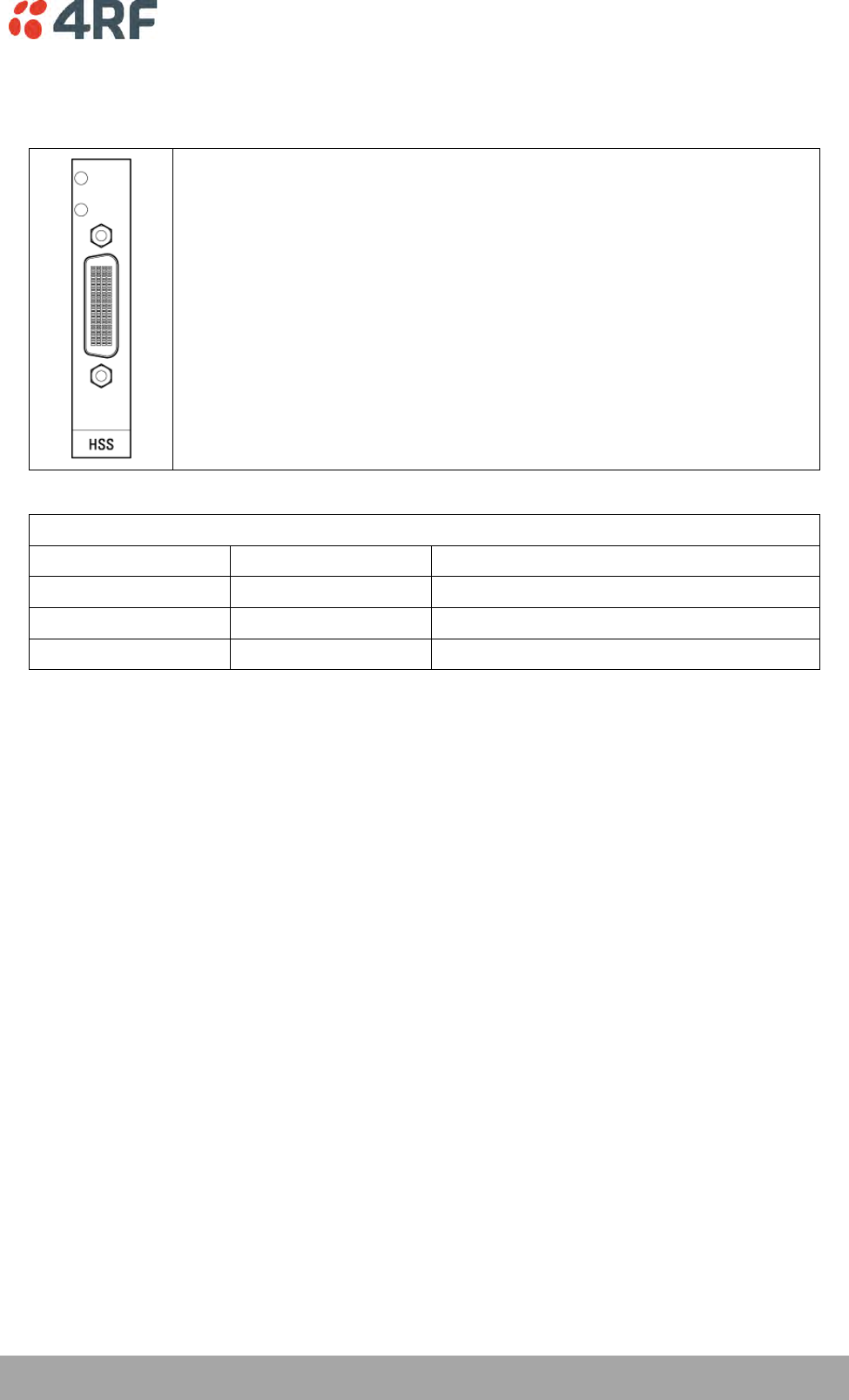
Interface Connections | 265
Aprisa XE User Manual
HSS Interface Connections
The connector on the high-speed synchronous serial interface is a high density
LFH-60 (as used on standard Cisco WAN port serial interface cables and
equivalents).
The interface specification (X.21 / V.35 etc) is automatically changed by simply
changing the type of interface cable connected to the HSS.
LED indicators
LED
Status
Explanation
Top green LED
On
Normal operation
Top green LED
Flashing
Loopback in place
Lower green LED
On
Normal operation
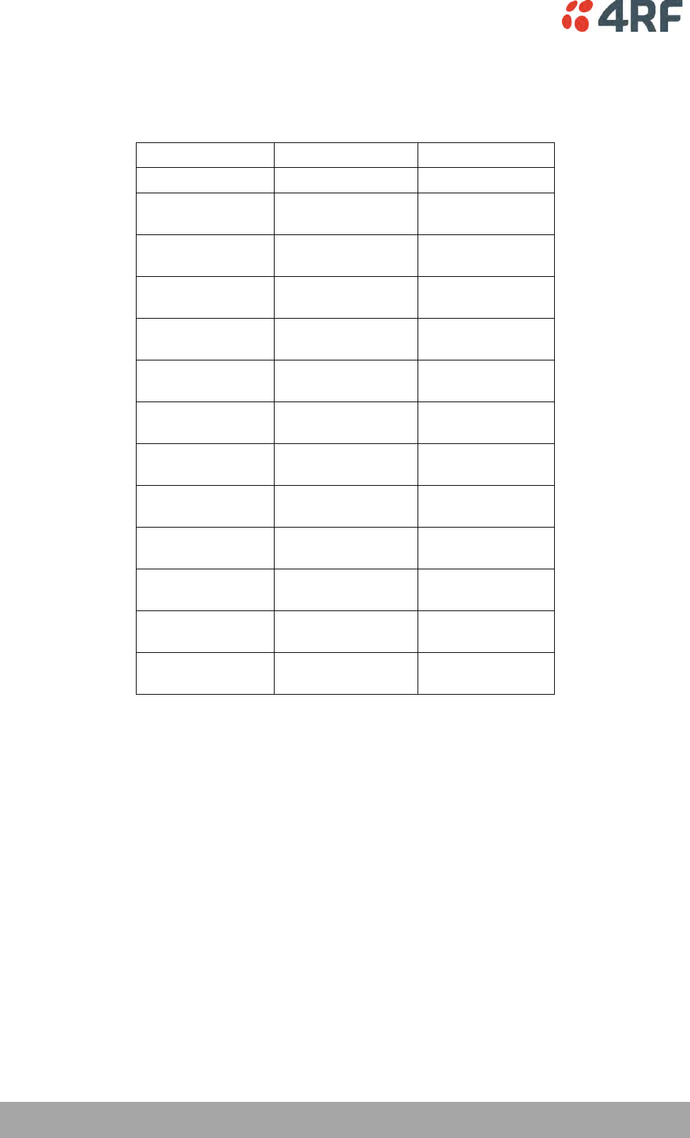
266 | Interface Connections
Aprisa XE User Manual
Synchronous cable assemblies
RS-449 Serial Cable Assembly for DCE (Part number: Cab Sync 449FC)
Pin number
Pin function
Direction
1
Shield Ground
-
4
22
SD+
SD-
Input
Input
5
23
ST+
ST-
Output
Output
6
24
RD+
RD-
Output
Output
7
25
RS+
RS-
Input
Input
8
26
RT+
RT-
Output
Output
9
27
CS+
CS-
Output
Output
10
37
LL
SC
Input
_
11
29
DM+
DM-
Output
Output
12
30
TR+
TR-
Input
Input
13
31
RR+
RR-
Output
Output
17
35
TT+
TT-
Input
Input
19
20
SG
RC
-
-
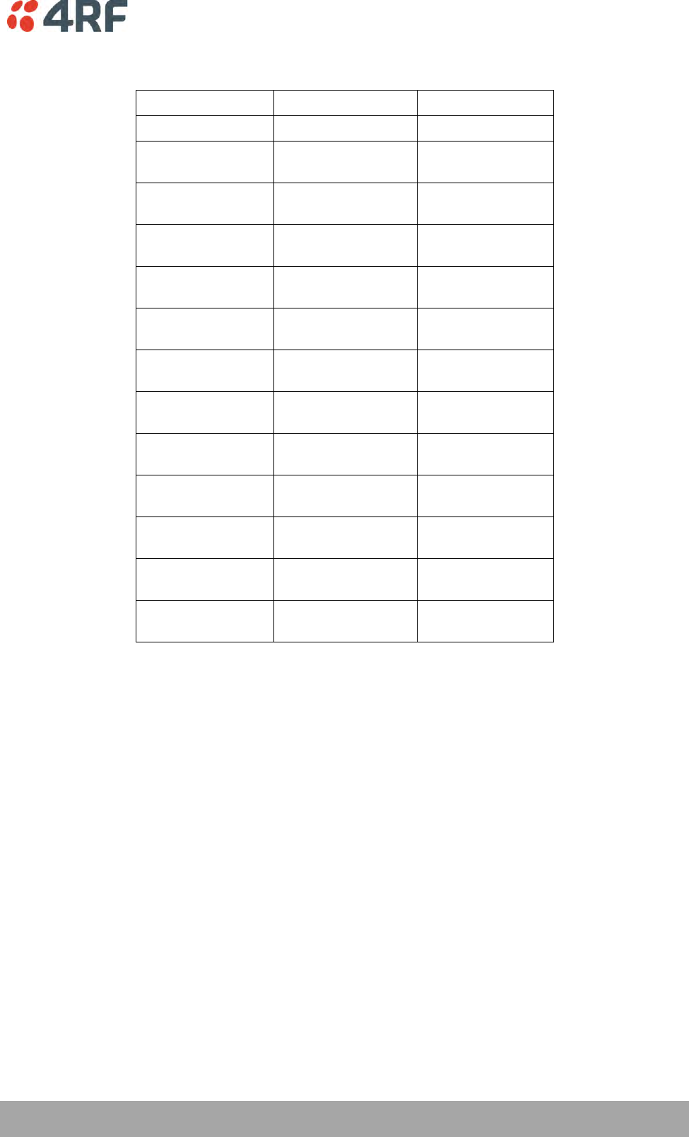
Interface Connections | 267
Aprisa XE User Manual
RS-449 Serial Cable Assembly for DTE (Part number: Cab Sync 449MT)
Pin number
Pin function
Direction
1
Shield Ground
_
4
22
SD+
SD-
Output
Output
5
23
ST+
ST-
Input
Input
6
24
RD+
RD-
Input
Input
7
25
RS+
RS-
Output
Output
8
26
RT+
RT-
Input
Input
9
27
CS+
CS-
Input
Input
10
37
LL
SC
Output
_
11
29
DM+
DM-
Input
Input
12
30
TR+
TR-
Output
Output
13
31
RR+
RR-
Input
Input
17
35
TT+
TT-
Output
Output
19
20
SG
RC
-
-
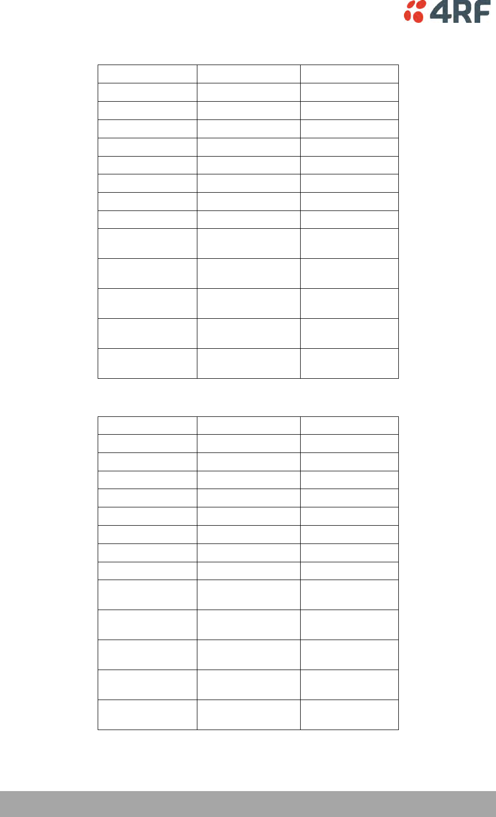
268 | Interface Connections
Aprisa XE User Manual
V.35 Serial Cable Assembly for DCE (Part number: Cab Sync V35FC)
Pin number
Pin function
Direction
A
Frame Ground
B
Circuit Ground
C
RTS
Input
D
CTS
Output
E
DSR
Output
F
RLSD
Output
H
DTR
Input
K
LT
Input
P
S
SD+
SD-
Input
Input
R
T
RD+
RD-
Output
Output
U
W
SCTE+
SCTE-
Input
Input
V
X
SCR+
SCR-
Output
Output
Y
AA
SCT+
SCT-
Output
Output
V.35 Serial Cable Assembly for DTE (Part number: Cab Sync V35MT)
Pin number
Pin function
Direction
A
Frame Ground
B
Circuit Ground
C
RTS
Output
D
CTS
Input
E
DSR
Input
F
RLSD
Input
H
DTR
Output
K
LT
Output
P
S
SD+
SD-
Output
Output
R
T
RD+
RD-
Input
Input
U
W
SCTE+
SCTE-
Output
Output
V
X
SCR+
SCR-
Input
Input
Y
AA
SCT+
SCT-
Input
Input

Interface Connections | 269
Aprisa XE User Manual
X.21 Serial Cable Assembly for DCE (Part number: Cab Sync X21FC)
Pin number
Pin function
Direction
1
Shield Ground
-
2
9
Transmit+
Transmit-
Input
Input
3
10
Control+
Control-
Input
Input
4
11
Receive+
Receive-
Output
Output
5
12
Indication+
Indication-
Output
Output
6
13
Timing+
Timing-
Output
Output
8
Circuit Ground
X.21 Serial Cable Assembly for DTE (Part number: Cab Sync X21MT)
Pin number
Pin function
Direction
1
Shield Ground
-
2
9
Transmit+
Transmit-
Output
Output
3
10
Control+
Control-
Output
Output
4
11
Receive+
Receive-
Input
Input
5
12
Indication+
Indication-
Input
Input
6
13
Timing+
Timing-
Input
Input
8
Circuit Ground
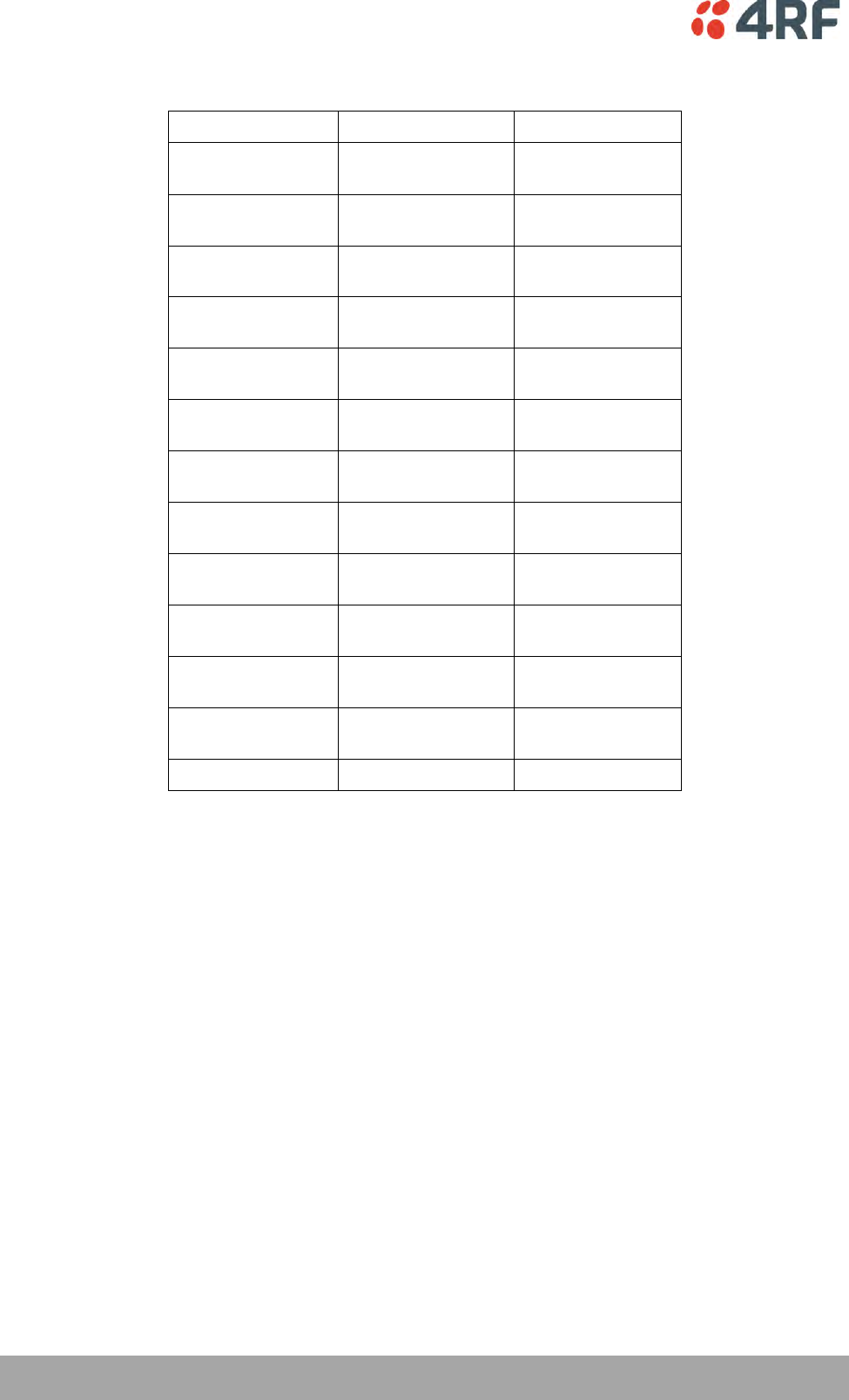
270 | Interface Connections
Aprisa XE User Manual
RS-530 Serial Cable Assembly for DCE (Part number: Cab Sync 530FC)
Pin number
Pin function
Direction
2
14
BA(A), TXD+
BA(B), TXD-
Input
Input
3
16
BB(A), RXD+
BB(B), RXD-
Output
Output
4
19
CA(A), RTS+
CA(B), RTS-
Input
Input
5
13
CB(A), CTS+
CB(B), CTS-
Output
Output
6
22
CC(A), DSR+
CC(B), DSR-
Output
Output
1
-
Shield
-
8
10
CF(A), DCD+
CF(B), DCD-
Output
Output
15
12
DB(A), TXC+
DB(B), TXC-
Output
Output
17
9
DD(A), RXC+
DD(B), RXC-
Output
Output
18
7
LL
Circuit Ground
Input
-
20
23
CD(A), DTR+
CD(B), DTR-
Input
Input
24
11
DA(A), TXCE+
DA(B), TXCE-
Input
Input
25
TM, not used
Output

Interface Connections | 271
Aprisa XE User Manual
RS-530 Serial Cable Assembly for DTE (Part number: Cab Sync 530MT)
Pin number
Pin function
Direction
2
14
BA(A), TXD+
BA(B), TXD-
Output
Output
3
16
BB(A), RXD+
BB(B), RXD-
Input
Input
4
19
CA(A), RTS+
CA(B), RTS-
Output
Output
5
13
CB(A), CTS+
CB(B), CTS-
Input
Input
6
22
CC(A), DSR+
CC(B), DSR-
Input
Input
1
-
Shield
-
8
10
CF(A), DCD+
CF(B), DCD-
Input
Input
15
12
DB(A), TXC+
DB(B), TXC-
Input
Input
17
9
DD(A), RXC+
DD(B), RXC-
Input
Input
18
7
LL
Circuit Ground
Output
-
20
23
CD(A), DTR+
CD(B), DTR-
Output
Output
24
11
DA(A), TXCE+
DA(B), TXCE-
Output
Output
25
TM, not used
Output

272 | Interface Connections
Aprisa XE User Manual
Cable WAN Connectors
Cisco LFH-60
cable name
WAN connector
Connector gender
Label on WAN end
449FC
DB-37
female
'to DTE'
449MT
DB-37
male
'to DCE'
V35FC
M34
female
'to DTE'
V35MT
M34
male
'to DCE'
X21FC
DB-15
female
'to DTE'
X21MT
DB-15
male
'to DCE'
530FC
DB-25
female
'to DTE'
530MT
DB-25
male
'to DCE'
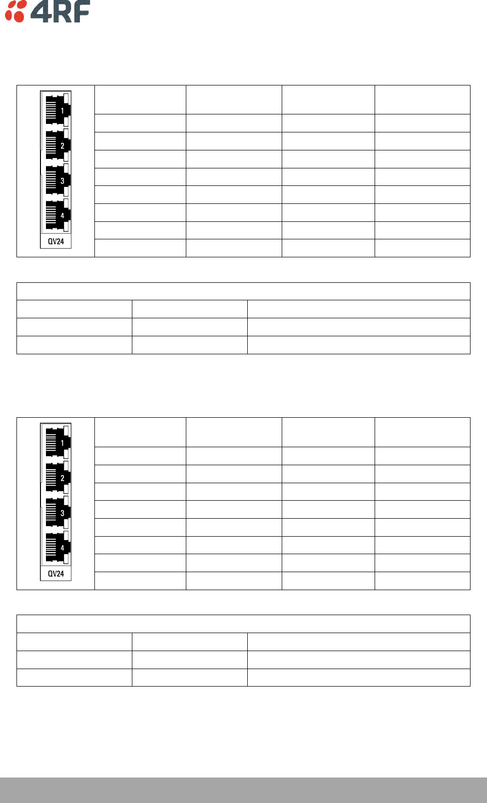
Interface Connections | 273
Aprisa XE User Manual
QV24 Interface connections
The QV24 is always configured as a DCE:
RJ45
Pin number
Pin function
Direction
TIA-568A wire
colour
1
RTS
Input
Green / white
2
DTR
Input
Green
3
TXD
Input
Orange / white
4
Ground
Blue
5
Ground
Blue / white
6
RXD
Output
Orange
7
DSR
Output
Brown / white
8
CTS
Output
Brown
RJ-45 connector LED indicators
LED
Status
Explanation
Green
On / flashing
Transmit data
Yellow
On / flashing
Receive data
QV24S Interface connections
The QV24S is always configured as a DCE:
RJ45
Pin number
Pin function
Direction
TIA-568A wire
colour
1
RTS
Input
Green / white
2
XTXC
Input
Green
3
TXD
Input
Orange / white
4
Ground
Blue
5
Ground
Blue / white
6
RXD
Output
Orange
7
RXC
Output
Brown / white
8
CTS
Output
Brown
RJ-45 connector LED indicators
LED
Status
Explanation
Green
On / flashing
Transmit data
Yellow
On / flashing
Receive data
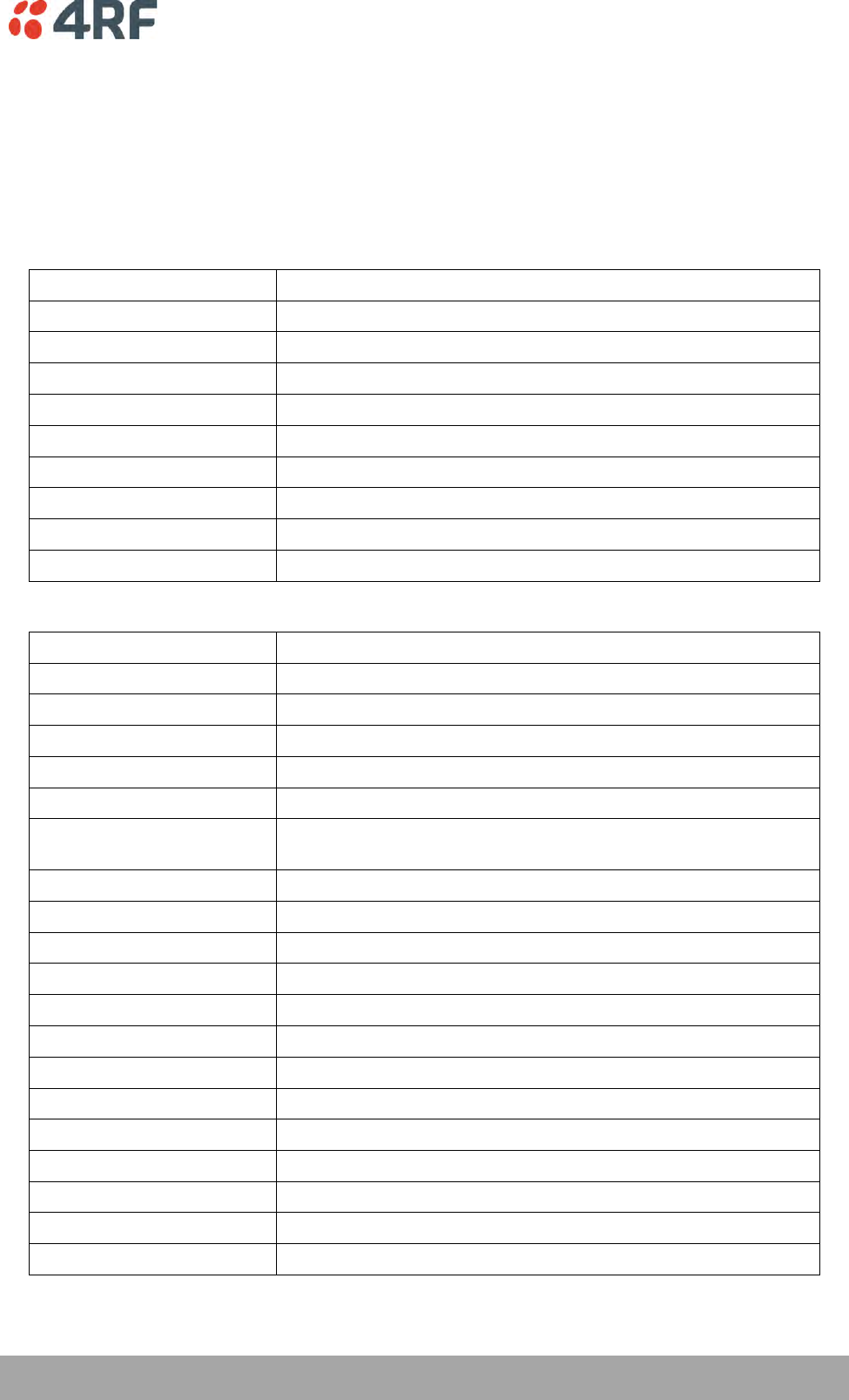
Alarm Types and Sources | 275
Aprisa XE User Manual
16. Alarm Types and Sources
Alarm Types
Transmitter Alarms
Transmitter Alarms for all Frequency Bands
Type
Explanation
tx11VFail
The transmitter 11 VDC power supply has failed
tx28VFail
The transmitter 28 VDC power supply has failed
tx5VFail
The transmitter 5 VDC power supply has failed
txAmplifierBalance
One side of the transmitter amplifier has failed
txEEFail
The transmitter on-board memory has failed
txMibFail
The transmitter MIB is corrupt in EEPROM
txReturnLoss
The transmitter return loss is high
txSynthLD
The transmitter synthesizer frequency is not set
txTSensorFail
The transmitter temperature sensor has failed
Transmitter Alarms for 300, 400, 600, 700, 800, 900, 1400 MHz Frequency Bands
txADCChZeroLo
The transmitter AGC voltage is low
txADCChZeroHi
The transmitter AGC voltage is high
txADCChOneLo
The transmitter Forward Power Monitor reading is low
txADCChOneHi
The transmitter Forward Power Monitor reading is high
txADCChTwoLo
The transmitter Reverse Power Monitor reading is low
txADCChTwoHi
The transmitter Reverse Power Monitor reading is high
txADCChThreeHi
The transmitter temperature is greater than 75°C and the
transmitter has shut down
txADCChFourLo
The transmitter synthesizer tuning voltage is low
txADCChFourHi
The transmitter synthesizer tuning voltage is high
txADCChFiveLo
The transmitter 28 VDC power supply voltage is low
txADCChFiveHi
The transmitter 28 VDC power supply voltage is high
txADCChSixLo
The transmitter 11 VDC power supply voltage is low
txADCChSixHi
The transmitter 11 VDC power supply voltage is high
txADCChSevenLo
The transmitter digital 5 VDC power supply voltage is low
txADCChSevenHi
The transmitter digital 5 VDC power supply voltage is high
txADCChEightLo
The transmitter reference 7 VDC power supply voltage is low
txADCChEightHi
The transmitter reference 7 VDC power supply voltage is high
txADCChNineLo
The transmitter VCO voltage is low
txADCChNineHi
The transmitter VCO voltage is high
txADCChElevenHi
The transmitter temperature is greater than 70°C.
276 | Alarm Types and Sources
Aprisa XE User Manual
Transmitter Alarms for 2000, 2500 MHz Frequency Bands
txADCChZeroLo
The transmitter AGC voltage is low
txADCChZeroHi
The transmitter AGC voltage is high
txADCChOneLo
The transmitter Forward Power Monitor reading is low
txADCChOneHi
The transmitter Forward Power Monitor reading is high
txADCChTwoLo
The transmitter Reverse Power Monitor reading is low
txADCChTwoHi
The transmitter Reverse Power Monitor reading is high
txADCChThreeHi
The transmitter temperature is greater than 75°C and the
transmitter has shut down
txADCChFourLo
The transmitter synthesizer tuning voltage is low
txADCChFourHi
The transmitter synthesizer tuning voltage is high
txADCChFiveLo
The transmitter 28 VDC power supply voltage is low
txADCChFiveHi
The transmitter 28 VDC power supply voltage is high
txADCChSixLo
The transmitter 9 VDC power supply voltage is low
txADCChSixHi
The transmitter 9 VDC power supply voltage is high
txADCChSevenLo
The transmitter digital 5 VDC power supply voltage is low
txADCChSevenHi
The transmitter digital 5 VDC power supply voltage is high
txADCChEightLo
The transmitter reference -5 VDC power supply voltage is low
txADCChEightHi
The transmitter reference -5 VDC power supply voltage is high
txADCChNineLo
The transmitter VCO voltage is low
txADCChNineHi
The transmitter VCO voltage is high
txADCChElevenHi
The transmitter temperature is greater than 70°C.
Alarm Types and Sources | 277
Aprisa XE User Manual
Receiver Alarms
Receiver Alarms for all Frequency Bands
Type
Explanation
rx12VFail
The receiver 12 VDC power supply has failed
rxEEFail
The on-board memory has failed
rxMibFail
The receiver MIB is corrupt in EEPROM
rxOff
The receiver is off
rxRSSIHi
The receiver maximum input level has been exceeded
rxRSSILo
The RSSI is below the alarm threshold setting (see page 80)
rxSynthLD
The synthesizer frequency is not set
Receiver Alarms for 300, 400, 600, 700, 800, 900 MHz Frequency Bands
rxADCChZeroLo
The receiver 3.3 VDC power supply voltage is low
rxADCChZeroHi
The receiver 3.3 VDC power supply voltage is high
rxADCChOneLo
The receiver synthesizer tuning voltage is low
rxADCChOneHi
The receiver synthesizer tuning voltage is high
rxADCChTwoLo
The receiver +12 VDC power supply is low
rxADCChTwoHi
The receiver +12 VDC power supply is high
rxADCChThreeLo
The receiver +5 VDC power supply is low
rxADCChThreeHi
The receiver +5 VDC power supply is high
rxADCChFourLo
The receiver +12 VDC power supply is low (same alarm as TwoLo)
rxADCChFourHi
The receiver +12 VDC power supply is high (same alarm as TwoHi)
rxADCChFiveLo
The receiver VCO voltage is low
rxADCChFiveHi
The receiver VCO voltage is high
rxADCChSevenLo
The receiver RSSI is lower than the normal operating lower limit
rxADCChSevenHi
The receiver RSSI is higher than the normal operating upper limit
rxADCChEightLo
The receiver temperature is greater than 70°C (below spec)
rxADCChEightHi
The receiver temperature is less than -10°C (below spec)
278 | Alarm Types and Sources
Aprisa XE User Manual
Receiver Alarms for 1400 MHz Frequency Band
rxADCChZeroLo
The receiver 3.3 VDC power supply voltage is low
rxADCChZeroHi
The receiver 3.3 VDC power supply voltage is high
rxADCChOneLo
The receiver synthesizer tuning voltage is low
rxADCChOneHi
The receiver synthesizer tuning voltage is high
rxADCChTwoLo
The receiver -1.5 VDC power supply is low
rxADCChTwoHi
The receiver -1.5 VDC power supply is high
rxADCChThreeLo
The receiver +5 VDC power supply is low
rxADCChThreeHi
The receiver +5 VDC power supply is high
rxADCChFourLo
The receiver +9 VDC power supply is low
rxADCChFourHi
The receiver +9 VDC power supply is high
rxADCChFiveLo
The receiver VCO voltage is low
rxADCChFiveHi
The receiver VCO voltage is high
rxADCChSevenLo
The receiver RSSI is lower than the normal operating lower limit
rxADCChSevenHi
The receiver RSSI is higher than the normal operating upper limit
rxADCChEightLo
The receiver temperature is greater than 70°C (below spec)
rxADCChEightHi
The receiver temperature is less than -10°C (below spec)
Alarm Types and Sources | 279
Aprisa XE User Manual
Receiver Alarms for 2000, 2500 MHz Frequency Bands
rxADCChZeroLo
The receiver 3.3 VDC power supply voltage is low
rxADCChZeroHi
The receiver 3.3 VDC power supply voltage is high
rxADCChOneLo
The receiver synthesizer tuning voltage is low
rxADCChOneHi
The receiver synthesizer tuning voltage is high
rxADCChTwoLo
The receiver +12 VDC power supply is low
rxADCChTwoHi
The receiver +12 VDC power supply is high
rxADCChThreeLo
The receiver +5 VDC power supply is low
rxADCChThreeHi
The receiver +5 VDC power supply is high
rxADCChFourLo
The receiver +9 VDC power supply is low
rxADCChFourHi
The receiver +9 VDC power supply is high
rxADCChFiveLo
The receiver VCO voltage is low
rxADCChFiveHi
The receiver VCO voltage is high
rxADCChSevenLo
The receiver RSSI is lower than the normal operating lower limit
rxADCChSevenHi
The receiver RSSI is higher than the normal operating upper limit
rxADCChEightLo
The receiver temperature is greater than 70°C (below spec)
rxADCChEightHi
The receiver temperature is less than -10°C (below spec)

280 | Alarm Types and Sources
Aprisa XE User Manual
MUX Alarms
Type
Explanation
muxInit
A MUX card failed to program
muxMibEEFail
The MIB EEROM is corrupt
muxCharEEFail
The character data is corrupt
Modem Alarms
Type
Explanation
mdLOS
The modem has loss of synchronization with the far end
mdDemodAlignmentLost
The modem is unable to synchronize to the payload framing
mdTdmAlignmentLost
The modem is unable to synchronize to the system bus timing
mdRefAFail
The modem reference clock A has failed
mdRefBFail
The modem reference clock B has failed
mdClkSyncFail
The modem is unable to synchronize to the system clock
mdEEFail
The modem EEPROM is corrupt
mdUCEPresent
The modem has uncorrectable errors
Motherboard Alarms
Type
Explanation
mbFan1Fail
Fan 1 failure
mbFan2Fail
Fan 2 failure
mbCardMismatch
The expected interface card is different to the card that is fitted
mbHwHsc
A MUX card has an unsupported HSC number
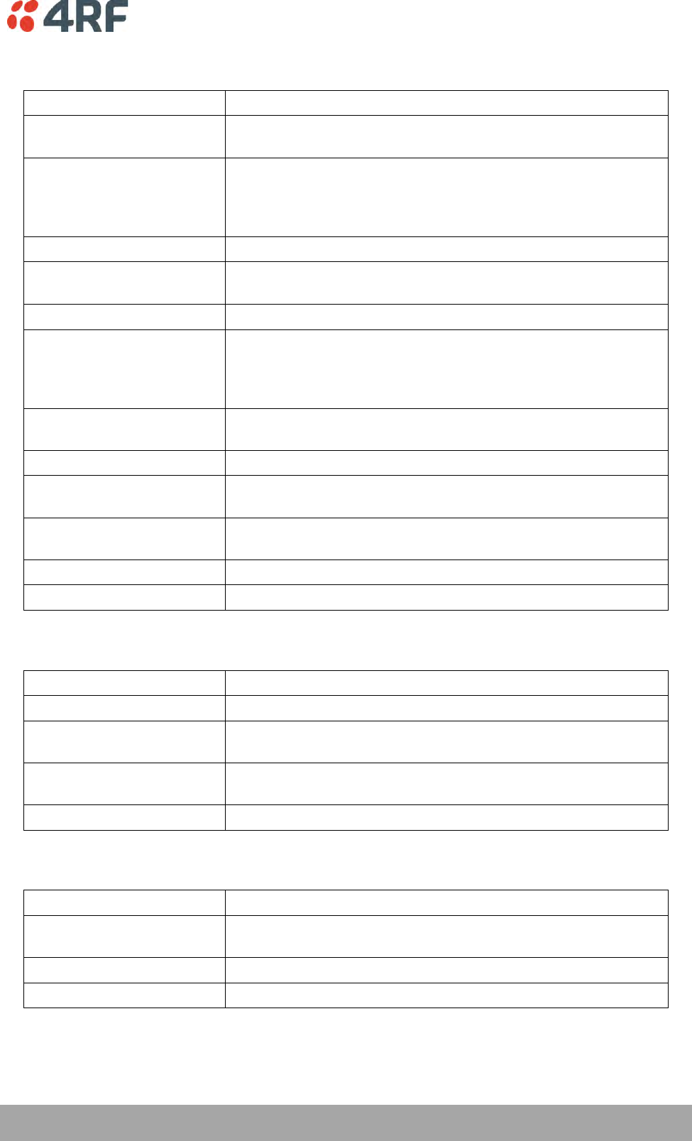
Alarm Types and Sources | 281
Aprisa XE User Manual
QJET Alarms
Type
Explanation
e1AIS
The E1 interface RX input has received an Alarm Indication Signal
from the downstream equipment.
e1RAI
The E1 interface RX input has received a Remote Alarm Indication
alarm (RAI) from the downstream equipment.
A remote alarm indicator signal is sent from the downstream
equipment when it has an active LOS or LOF alarm.
e1LOS
The E1 interface Loss Of Signal alarm (LOS)
e1CRC4
The E1 interface Cyclic Redundancy Check 4 alarm indicates a loss
of or corrupted CRC data.
e1LOF
The E1 interface Loss Of Frame alignment (LOF)
e1RMAI
The E1 interface RX input has received an RMAI from the
downstream equipment.
A TS16 remote alarm indicator signal is sent from the downstream
equipment when it has an active TS16 LOS or LOF alarm.
e1TS16AIS
The E1 interface RX input has received a TS16 Alarm Indication
Signal from the downstream equipment.
e1TS16LOS
The E1 timeslot 16 Loss Of Signal alarm
t1AIS
The T1 interface RX input has received an Alarm Indication Signal
from the downstream equipment (AIS Received alarm)
t1RAI
The T1 interface RX input has received a Remote Alarm Indication
alarm (RAI) from the downstream equipment.
t1LOS
The T1 interface Loss Of Signal alarm (LOS)
t1LOF
The T1 interface Loss Of Frame alignment (LOF)
DFXO Alarms
Type
Explanation
fxoCodecOvld
The DFXO detected a codec receive signal overload
fxoBillToneOvld
The DFXO detected a billing tone input signal overload (greater
than 0.8 Vrms into 200 Ω)
fxoUnplug
The DFXO detected that the exchange line has been unplugged
from interface
fxoCurrentOvld
The DFXO Loop current overload detected (greater than 100 mA)
DFXS Alarms
Type
Explanation
fxsCalibError
The phone was off-hook during the DFXS initialization phase
(during power up)
fxsDCDCError
The DFXS DC-DC converter has a low battery voltage error
fxsCasLock
The DFXS has a loss of CAS lock
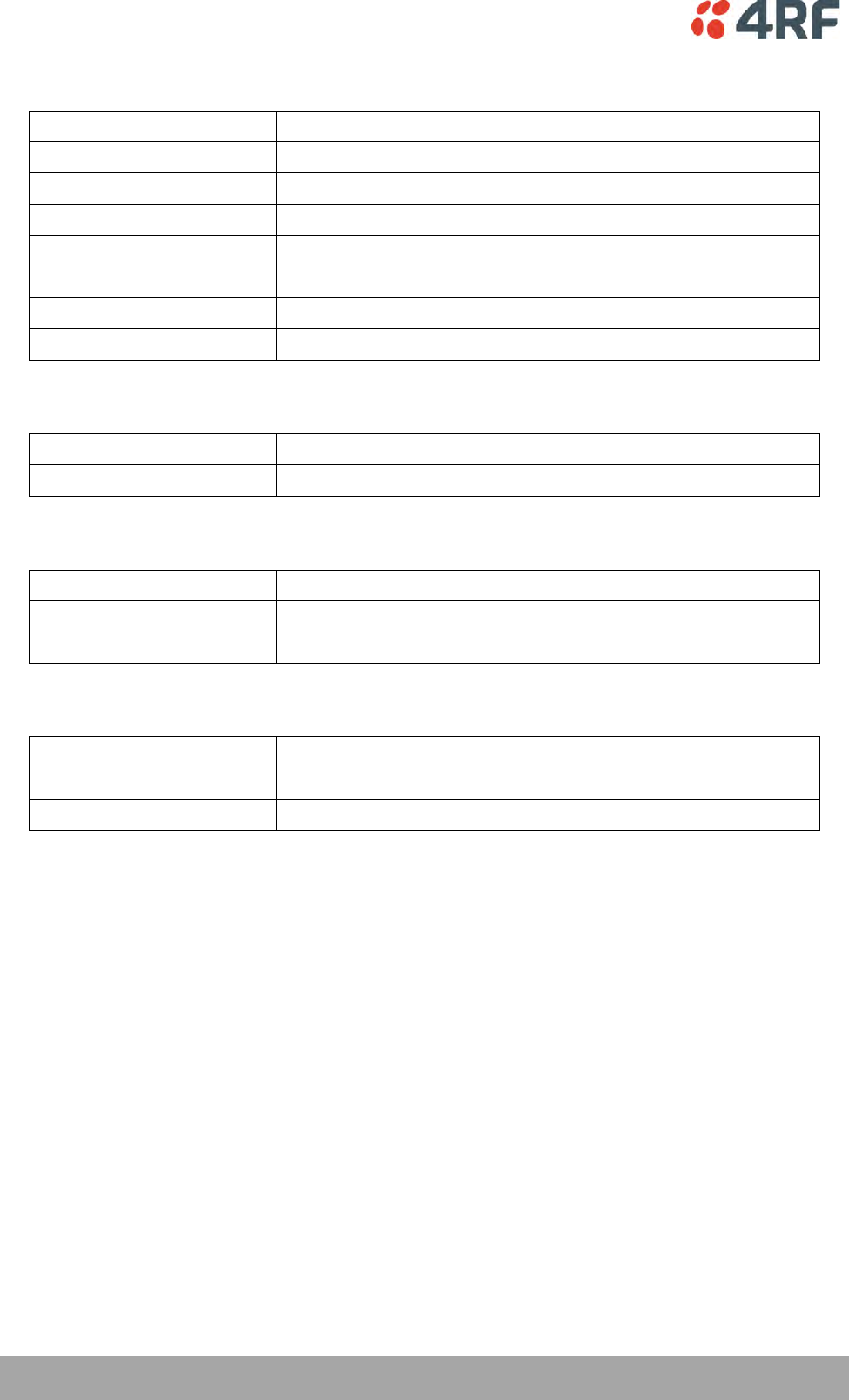
282 | Alarm Types and Sources
Aprisa XE User Manual
HSS Alarms
Type
Explanation
hssLoss
The HSS has a loss of control pattern
hssRxFifoFull
The HSS RX FIFO has an overrun
hssRxFifoEmpty
The HSS RX FIFO has an underrun
hssTxFifoFull
The HSS TX FIFO has an overrun
hssTxFifoEmpty
The HSS TX FIFO has an underrun
hssRxClockInvalid
The HSS RX clock is invalid
hssTxClockInvalid
The HSS TX clock is invalid
QV24 Alarms
Type
Explanation
v24CtrlLineLoss
The V.24 control lines are not in sync.
External Alarm Inputs
Type
Explanation
externalAlarm1
There has been an alarm on external alarm input 1.
externalAlarm2
There has been an alarm on external alarm input 2.
Remote Terminal Alarms
Type
Explanation
remoteMajorAlarm
There has been a major alarm on the remote terminal.
remoteMinorAlarm
There has been a minor alarm on the remote terminal.
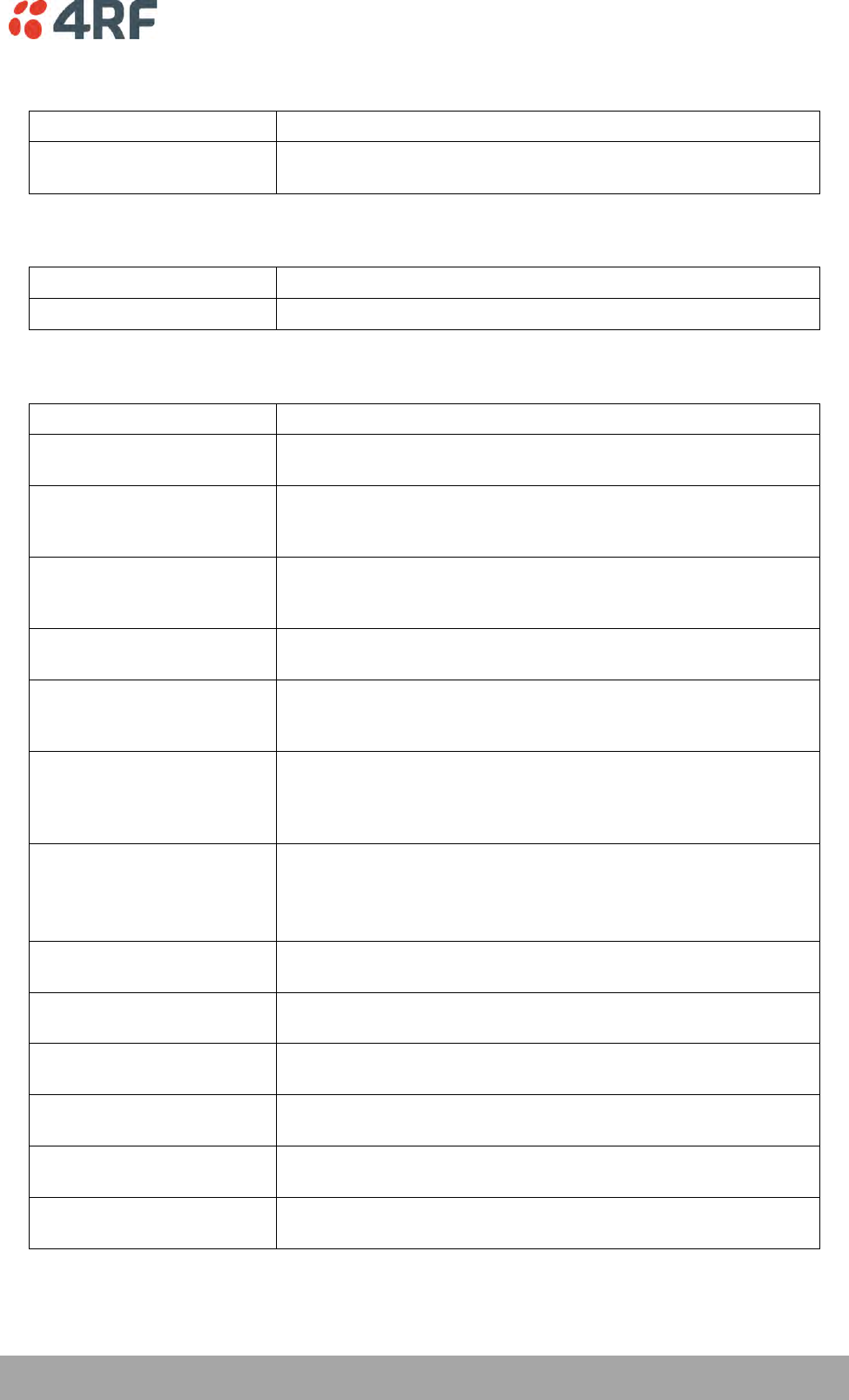
Alarm Types and Sources | 283
Aprisa XE User Manual
Cross Connect Alarms
Type
Explanation
ccNoBandwidth
There is insufficient bandwidth for the current cross connection
configuration.
MHSB Alarms
Type
Explanation
mhsbSwitchToStandby
The terminal has switched from active to standby.
HSD Alarms
Type
Explanation
Mode Switch Software
Override
This alarm provides a warning if the SuperVisor ‘Active Radio’ HSD
Control has overwritten the PSC Mode Switch.
Companion Tx Fail
This alarm occurs on Radio A if the Radio B transmitter (HSD
Companion) has failed. This alarm could be caused by a missing
RF cable between Radio A and Radio B.
hsdCompanionLost
This alarm occurs if there is no traffic from the HSD Companion
radio. This alarm could be caused by a missing traffic cable
between Radio A PSC card and Radio B PIC card.
pscMuxAlignmentError
This alarm occurs if the TDM mux loses alignment to the TDM bus.
This alarm could be caused by a Radio A PSC hardware failure.
pscDemuxAlignmentLost
This alarm occurs if there is a change in state of the PSC Demux
alignment. This alarm could be caused by a HSD system receiver
signal loss (both Radio A and Radio B).
pscTDMAlignmentLost
This alarm occurs if there is a change in state of the PSC TDM
alignment. This alarm could be caused by a HSD system receiver
signal loss (both Radio A and Radio B) or a Radio A PSC hardware
failure.
hsdParamMismatch
This alarm occurs if there is a parameter setting mismatch
between Radio A and Radio B.
The Parameter Mismatch alarms only occur if the HSD Control
‘Parameter Compare Checking’ option is set to ‘On’.
hsdPMTxPower
This alarm occurs if there is a parameter mismatch between
Radio A and Radio B transmitter power setting.
hsdPMTermRfChWidth
This alarm occurs if there is a parameter mismatch between
Radio A and Radio B channel size setting.
hsdPMTxFreq
This alarm occurs if there is a parameter mismatch between
Radio A and Radio B transmitter frequency setting.
hsdPMRxFreq
This alarm occurs if there is a parameter mismatch between
Radio A and Radio B receiver frequency setting.
hsdPMTermModState
This alarm occurs if there is a parameter mismatch between
Radio A and Radio B modulation setting.
hsdPMModemIntlvEna
This alarm occurs if there is a parameter mismatch between
Radio A and Radio B modem interleaver setting.

284 | Alarm Types and Sources
Aprisa XE User Manual
Software Alarms
Type
Explanation
Upload Fail
An Upload Fail alarm occurs if the TFTP Upgrade process fails.
This can indicate that the upgrade process cannot find the TFTP
server or cannot find the software version number entered.
defaultImageTableUsed
A default image table alarm indicates that the image table has
been rebuilt from defaults. This can indicate that an incorrect
build of software is running on the terminal.
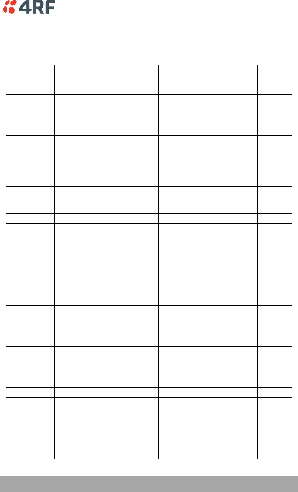
Country Specific Settings | 285
Aprisa XE User Manual
17. Country Specific Settings
The following table shows the country-specific settings for the DFXO / DFXS interface cards. If the country
you want is not listed, contact the local telephone company for assistance.
Country
DFXO / DFXS Termination / balance
impedance
DFXO
loop
current
limiter
DFXO
on-hook
speed
DFXO
ringing
impedance
DFXO
ringing
detection
threshold
Argentina
600Ω
On
< 500 μs
> 1 MΩ
16 Vrms
Australia
TN12 220Ω + (820Ω ║ 120nF)
On
26 ms
> 1 MΩ
16 Vrms
Austria
TBR21 270Ω + (750Ω ║ 150nF)
On
3 ms
> 1 MΩ
16 Vrms
Bahrain
TBR21 270Ω + (750Ω ║ 150nF)
On
3 ms
> 1 MΩ
16 Vrms
Belgium
TBR21 270Ω + (750Ω ║ 150nF)
On
3 ms
> 1 MΩ
16 Vrms
Brazil
600Ω
On
< 500 μs
> 1 MΩ
16 Vrms
Bulgaria
220Ω + (820Ω ║ 120nF)
On
3 ms
> 1 MΩ
16 Vrms
Canada
600Ω
On
< 500 μs
> 1 MΩ
16 Vrms
Chile
600Ω
On
< 500 μs
> 1 MΩ
16 Vrms
China
600Ω and
China 200Ω + (680Ω ║ 100nF)
On
< 500 μs
> 1 MΩ
16 Vrms
Colombia
600Ω
On
< 500 μs
> 1 MΩ
16 Vrms
Croatia
TBR21 270Ω + (750Ω ║ 150nF)
On
3 ms
> 1 MΩ
16 Vrms
Cyprus
TBR21 270Ω + (750Ω ║ 150nF)
On
3 ms
> 1 MΩ
16 Vrms
Czech Republic
TBR21 270Ω + (750Ω ║ 150nF)
On
3 ms
> 1 MΩ
16 Vrms
Denmark
TBR21 270Ω + (750Ω ║ 150nF)
On
3 ms
> 1 MΩ
16 Vrms
Ecuador
600Ω
On
< 500 μs
> 1 MΩ
16 Vrms
Egypt
TBR21 270Ω + (750Ω ║ 150nF)
On
3 ms
> 1 MΩ
16 Vrms
El Salvador
600Ω
On
< 500 μs
> 1 MΩ
16 Vrms
Finland
TBR21 270Ω + (750Ω ║ 150nF)
On
3 ms
> 1 MΩ
16 Vrms
France
TBR21 270Ω + (750Ω ║ 150nF)
On
3 ms
> 1 MΩ
16 Vrms
Germany
TBR21 270Ω + (750Ω ║ 150nF)
On
3 ms
> 1 MΩ
16 Vrms
Greece
TBR21 270Ω + (750Ω ║ 150nF)
On
3 ms
> 1 MΩ
16 Vrms
Guam
600Ω
On
< 500 μs
> 1 MΩ
16 Vrms
Hong Kong
600Ω
On
< 500 μs
> 1 MΩ
16 Vrms
Hungary
TBR21 270Ω + (750Ω ║ 150nF)
On
3 ms
> 1 MΩ
16 Vrms
Iceland
TBR21 270Ω + (750Ω ║ 150nF)
On
3 ms
> 1 MΩ
16 Vrms
India
600Ω
On
< 500 μs
> 1 MΩ
16 Vrms
Indonesia
600Ω
On
< 500 μs
> 1 MΩ
16 Vrms
Ireland
TBR21 270Ω + (750Ω ║ 150nF)
On
3 ms
> 1 MΩ
16 Vrms
Israel
TBR21 270Ω + (750Ω ║ 150nF)
On
3 ms
> 1 MΩ
16 Vrms
Italy
TBR21 270Ω + (750Ω ║ 150nF)
On
3 ms
> 1 MΩ
16 Vrms
Japan
600Ω
On
< 500 μs
> 1 MΩ
16 Vrms
Jordan
600Ω
On
< 500 μs
> 1 MΩ
16 Vrms
Kazakhstan
600Ω
On
< 500 μs
> 1 MΩ
16 Vrms
Kuwait
600Ω
On
< 500 μs
> 1 MΩ
16 Vrms
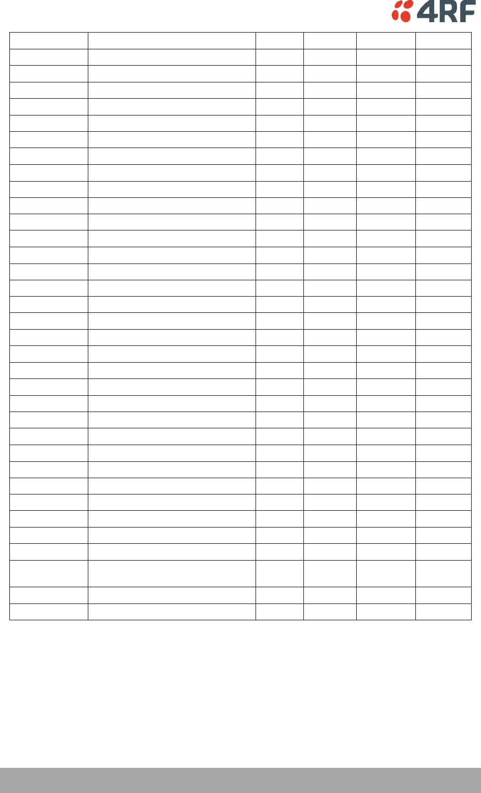
286 | Country Specific Settings
Aprisa XE User Manual
Latvia
TBR21 270Ω + (750Ω ║ 150nF)
On
3 ms
> 1 MΩ
16 Vrms
Lebanon
TBR21 270Ω + (750Ω ║ 150nF)
On
3 ms
> 1 MΩ
16 Vrms
Luxembourg
TBR21 270Ω + (750Ω ║ 150nF)
On
3 ms
> 1 MΩ
16 Vrms
Macao
600Ω
On
< 500 μs
> 1 MΩ
16 Vrms
Malaysia
600Ω
On
< 500 μs
> 1 MΩ
16 Vrms
Malta
TBR21 270Ω + (750Ω ║ 150nF)
On
3 ms
> 1 MΩ
16 Vrms
Mexico
600Ω
On
< 500 μs
> 1 MΩ
16 Vrms
Morocco
TBR21 270Ω + (750Ω ║ 150nF)
On
3 ms
> 1 MΩ
16 Vrms
Netherlands
TBR21 270Ω + (750Ω ║ 150nF)
On
3 ms
> 1 MΩ
16 Vrms
New Zealand
BT3 (370Ω + (620Ω ║ 310nF))
On
< 500 μs
> 1 MΩ
16 Vrms
Nigeria
TBR21 270Ω + (750Ω ║ 150nF)
On
3 ms
> 1 MΩ
16 Vrms
Norway
TBR21 270Ω + (750Ω ║ 150nF)
On
3 ms
> 1 MΩ
16 Vrms
Oman
600Ω
On
< 500 μs
> 1 MΩ
16 Vrms
Pakistan
600Ω
On
< 500 μs
> 1 MΩ
16 Vrms
Peru
600Ω
On
< 500 μs
> 1 MΩ
16 Vrms
Philippines
600Ω
On
< 500 μs
> 1 MΩ
16 Vrms
Poland
TBR21 270Ω + (750Ω ║ 150nF)
On
3 ms
> 1 MΩ
16 Vrms
Portugal
TBR21 270Ω + (750Ω ║ 150nF)
On
3 ms
> 1 MΩ
16 Vrms
Romania
TBR21 270Ω + (750Ω ║ 150nF)
On
3 ms
> 1 MΩ
16 Vrms
Russia
600Ω
On
< 500 μs
> 1 MΩ
16 Vrms
Saudi Arabia
600Ω
On
< 500 μs
> 1 MΩ
16 Vrms
Singapore
600Ω
On
< 500 μs
> 1 MΩ
16 Vrms
Slovakia
TBR21 270Ω + (750Ω ║ 150nF)
On
3 ms
> 1 MΩ
16 Vrms
Slovenia
TBR21 270Ω + (750Ω ║ 150nF)
On
3 ms
> 1 MΩ
16 Vrms
South Africa
TBR21 270Ω + (750Ω ║ 150nF)
On
< 500 μs
> 12 kΩ
16 Vrms
South Korea
600Ω
On
< 500 μs
> 12 kΩ
16 Vrms
Spain
TBR21 270Ω + (750Ω ║ 150nF)
On
3 ms
> 1 MΩ
16 Vrms
Sweden
TBR21 270Ω + (750Ω ║ 150nF)
On
3 ms
> 1 MΩ
16 Vrms
Switzerland
TBR21 270Ω + (750Ω ║ 150nF)
On
3 ms
> 1 MΩ
16 Vrms
Taiwan
600Ω
On
< 500 μs
> 1 MΩ
16 Vrms
Thailand
600Ω
On
< 500 μs
> 1 MΩ
16 Vrms
UAE
600Ω
On
< 500 μs
> 1 MΩ
16 Vrms
UK
BT Network 320Ω + (1050Ω ║ 230nF)
and TBR21 270Ω + (750Ω ║ 150nF)
On
3 ms
> 1 MΩ
16 Vrms
USA
600Ω
On
< 500 μs
> 1 MΩ
16 Vrms
Yemen
600Ω
On
< 500 μs
> 1 MΩ
16 Vrms
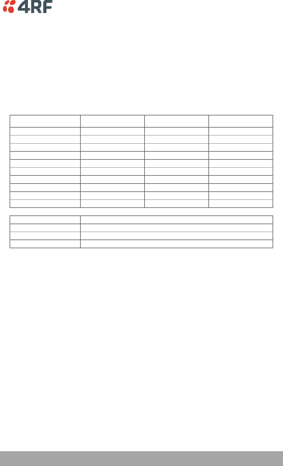
Specifications | 287
Aprisa XE User Manual
18. Specifications
RF Specifications
ETSI
Frequency Bands ETSI
Frequency Bands ETSI
Frequency Bands ETSI Frequency
Band
Frequency
Tuning Range
Synthesizer
Step Size
300 MHz 330 - 400 MHz 6.25 kHz
400 MHz 394 - 460 MHz 5.0 kHz
400 MHz 400 - 470 MHz 6.25 kHz
600 MHz 620 - 715 MHz 12.5 kHz
800 MHz 805 - 890 MHz 12.5 kHz
900 MHz 850 - 960 MHz 12.5 kHz
1400 MHz 1350 - 1550 MHz 12.5 kHz
1800 MHz 1700 - 2100 MHz 62.5 kHz
2000 MHz 1900 - 2300 MHz 62.5 kHz
2500 MHz 2300 - 2700 MHz 62.5 kHz
Modulation
Frequency stability (short term)
Frequency stability (long term)
Antenna connector
Note 1 Frequency Ranges Country specific frequency ranges within the above tuning ranges can be accommodated
Note 2 Modulation 128 QAM is unreleased: Please contact 4RF for availability.
Note 3 Frequency stability
Short term frequency stability is defined as changes in frequency due to environmental effects and power supply
variations
Long term frequency stability is defined as changes in frequency due to aging of crystal oscillators approx over 5
years
16 / 32 / 64 / 128 QAM and QPSK (software configurable)
< ±2 ppm
N-type female 50 Ω
< ±1 ppm
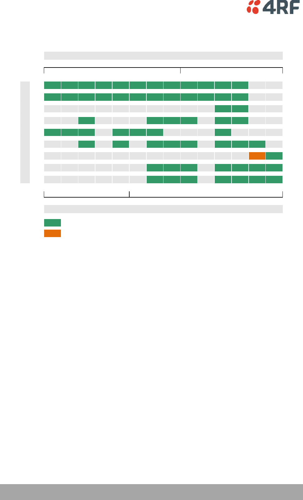
288 | Specifications
Aprisa XE User Manual
Product Range ETSI
The Aprisa XE terminal provides the following ETSI frequency bands / channel sizes:
25 50 75 125 150 200 250 500 1.00 1.35 1.75 3.50 7.00 14.00
300
400
600
800
900
1400
1800
2000
2500
112 256 400 640 808 1.02 1.24 2.39 4.89 6.62 8.63 17.18 35.51 65.46
Product Released
Product Release Pending
Frequency Band MHz
Transport capacity @ 64 QAM
Channel Size
kHz
MHz
kbit/s
Mbit/s
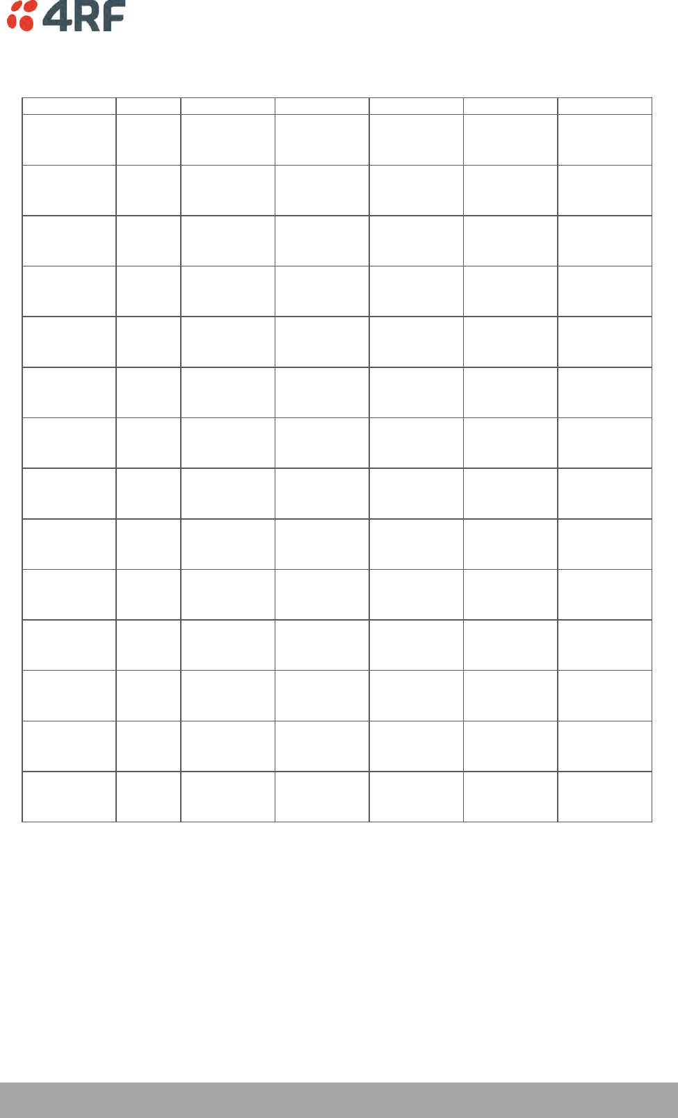
Specifications | 289
Aprisa XE User Manual
Link Capacity ETSI
Channel size QPSK 16 QAM 32 QAM 64 QAM 128 QAM
25 kHz Gross 72 kbit/s 96 kbit/s 112 kbit/s 136 kbit/s
E1 1 timeslot 1 timeslot 1 timeslot 2 timeslots
Wayside 8 kbit/s 32 kbit/s 48 kbit/s 8 kbit/s
50 kHz Gross 80 kbit/s 168 kbit/s 208 kbit/s 256 kbit/s 296 kbit/s
E1 1 timeslot 2 timeslots 3 timeslots 4 timeslots 4 timeslots
Wayside 16 kbit/s 40 kbit/s 16 kbit/s 0 kbit/s 40 kbit/s
75 kHz Gross 128 kbit/s 264 kbit/s 312 kbit/s 400 kbit/s 440 kbit/s
E1 2 timeslots 4 timeslots 4 timeslots 6 timeslots 6 timeslots
Wayside 0 kbit/s 8 kbit/s 56 kbit/s 16 kbit/s 56 kbit/s
125 kHz Gross 208 kbit/s 424 kbit/s 536 kbit/s 640 kbit/s 744 kbit/s
E1 3 timeslots 6 timeslots 8 timeslots 10 timeslots 11 timeslots
Wayside 16 kbit/s 40 kbit/s 24 kbit/s 0 kbit/s 40 kbit/s
150 kHz Gross 264 kbit/s 536 kbit/s 672 kbit/s 808 kbit/s 944 kbit/s
E1 4 timeslots 8 timeslots 10 timeslots 12 timeslots 14 timeslots
Wayside 8 kbit/s 24 kbit/s 32 kbit/s 40 kbit/s 48 kbit/s
200 kHz Gross 336 kbit/s 680 kbit/s 840 kbit/s 1024 kbit/s 1168 kbit/s
E1 5 timeslots 10 timeslots 13 timeslots 16 timeslots 18 timeslots
Wayside 16 kbit/s 40 kbit/s 8 kbit/s 0 kbit/s 16 kbit/s
250 kHz Gross 408 kbit/s 824 kbit/s 1032 kbit/s 1240 kbit/s 1448 kbit/s
E1 6 timeslots 12 timeslots 16 timeslots 19 timeslots 22 timeslots
Wayside 24 kbit/s 56 kbit/s 8 kbit/s 24 kbit/s 40 kbit/s
500 kHz Gross 792 kbit/s 1592 kbit/s 1992 kbit/s 2392 kbit/s 2792 kbit/s
E1 12 timeslots 24 timeslots 31 timeslots 1 E1 1 E1
Wayside 24 kbit/s 56 kbit/s 8 kbit/s 304 kbit/s 704 kbit/s
1.0 MHz Gross 1624 kbit/s 3256 kbit/s 4072 kbit/s 4888 kbit/s 5704 kbit/s
E1 25 timeslots 1 E1 1 E1 2 E1s 2 E1s
Wayside 24 kbit/s 1168 kbit/s 1984 kbit/s 712 kbit/s 1528 kbit/s
1.35 MHz Gross 2200 kbit/s 4408 kbit/s 5512 kbit/s 6616 kbit/s 7720 kbit/s
E1 1 E1 2 E1s 2 E1s 3 E1s 3 E1s
Wayside 112 kbit/s 232 kbit/s 1336 kbit/s 352 kbit/s 1456 kbit/s
1.75 MHz Gross 2872 kbit/s 5752 kbit/s 7192 kbit/s 8632 kbit/s 10072 kbit/s
E1 1 E1 2 E1s 3 E1s 4 E1s 4 E1s
Wayside 784 kbit/s 1576 kbit/s 928 kbit/s 280 kbit/s 1720 kbit/s
3.5 MHz Gross 5720 kbit/s 11448 kbit/s 14312 kbit/s 17176 kbit/s 20040 kbit/s
E1 2 E1s 5 E1s 6 E1s 8 E1s 9 E1s
Wayside 1544 kbit/s 1008 kbit/s 1784 kbit/s 472 kbit/s 1248 kbit/s
7.0 MHz Gross 11832 kbit/s 23672 kbit/s 29592 kbit/s 35512 kbit/s 41432 kbit/s
E1 5 E1s 11 E1s 14 E1s 17 E1s 19 E1s
Wayside 1392 kbit/s 704 kbit/s 360 kbit/s 16 kbit/s 1760 kbit/s
14 MHz Gross 23992 kbit/s 47992 kbit/s 59992 kbit/s 65464 kbit/s 65400 kbit/s
E1 11 E1s 22 E1s 28 E1s 28 E1s 28 E1s
Wayside 1024 kbit/s 2056 kbit/s 1528 kbit/s 7000 kbit/s 6936 kbit/s
Notes The capacities specified are for Unframed E1 and so require 2088 kbit/s to transport via the radio.
The management ethernet capacity must be subtracted from the gross capacity (default 64 kbit/s).
See Product Range table for Channel Size / Frequency Band cross reference
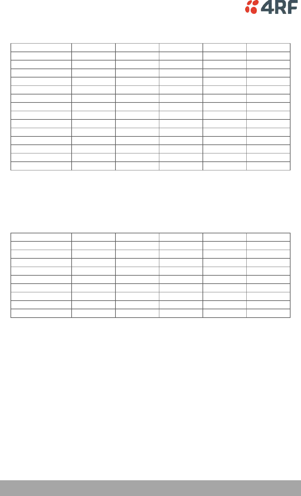
290 | Specifications
Aprisa XE User Manual
Receiver Sensitivity ETSI
Channel size QPSK 16 QAM 32 QAM 64 QAM 128 QAM
25 kHz NA -105 dBm -102 dBm -99 dBm -96 dBm
50 kHz -109 dBm -103 dBm -100 dBm -97 dBm -94 dBm
75 kHz -107 dBm -101 dBm -98 dBm -95 dBm -92 dBm
125 kHz -105 dBm -99 dBm -96 dBm -93 dBm -90 dBm
150 kHz -104 dBm -98 dBm -95 dBm -92 dBm -89 dBm
200 kHz -102 dBm -96 dBm -93 dBm -90 dBm -87 dBm
250 kHz -101 dBm -95 dBm -92 dBm -89 dBm -86 dBm
500 kHz -99 dBm -93 dBm -90 dBm -87 dBm -84 dBm
1.0 MHz -96 dBm -90 dBm -87 dBm -84 dBm -81 dBm
1.35 MHz -95 dBm -89 dBm -86 dBm -83 dBm -80 dBm
1.75 MHz -94 dBm -88 dBm -85 dBm -82 dBm -79 dBm
3.5 MHz -90 dBm -84 dBm -81 dBm -78 dBm -75 dBm
7.0 MHz -87 dBm -81 dBm -78 dBm -75 dBm -72 dBm
14 MHz -84 dBm -78 dBm -75 dBm -72 dBm -69 dBm
Notes
Typical performance specified at the antenna port for 10-6 BER.
The receiver is typically 1 dB more sensitive for a BER of 10-3.
NA (Not Available)
Transmitter Power ETSI
Frequency Band QPSK 16 QAM 32 QAM 64 QAM 128 QAM
300 MHz 21 to 35 dBm 17 to 31 dBm 16 to 30 dBm 15 to 29 dBm 15 to 29 dBm
400 MHz 21 to 35 dBm 17 to 31 dBm 16 to 30 dBm 15 to 29 dBm 15 to 29 dBm
600 MHz 21 to 35 dBm 17 to 31 dBm 16 to 30 dBm 15 to 29 dBm 15 to 29 dBm
800 MHz 21 to 35 dBm 17 to 31 dBm 16 to 30 dBm 15 to 29 dBm 15 to 29 dBm
900 MHz 21 to 35 dBm 17 to 31 dBm 16 to 30 dBm 15 to 29 dBm 15 to 29 dBm
1400 MHz 21 to 35 dBm 17 to 31 dBm 16 to 30 dBm 15 to 29 dBm 15 to 29 dBm
1800 MHz 21 to 35 dBm 17 to 31 dBm 16 to 30 dBm 15 to 29 dBm 15 to 29 dBm
2000 MHz 20 to 34 dBm 17 to 31 dBm 16 to 30 dBm 15 to 29 dBm 15 to 29 dBm
2500 MHz 20 to 34 dBm 17 to 31 dBm 16 to 30 dBm 15 to 29 dBm 15 to 29 dBm

Specifications | 291
Aprisa XE User Manual
System Gain ETSI
Channel Size QPSK 16 QAM 32 QAM 64 QAM 128 QAM
25 kHz NA 136 dB 132 dB 128 dB 125 dB
50 kHz 144 dB 134 dB 130 dB 126 dB 123 dB
75 kHz 142 dB 132 dB 128 dB 124 dB 121 dB
125 kHz 140 dB 130 dB 126 dB 122 dB 119 dB
150 kHz 139 dB 129 dB 125 dB 121 dB 118 dB
200 kHz 137 dB 127 dB 123 dB 119 dB 116 dB
250 kHz 136 dB 126 dB 122 dB 118 dB 115 dB
500 kHz 134 dB 124 dB 120 dB 116 dB 113 dB
1.0 MHz 131 dB 121 dB 117 dB 113 dB 110 dB
1.35 MHz 130 dB 120 dB 116 dB 112 dB 109 dB
1.75 MHz 129 dB 119 dB 115 dB 111 dB 108 dB
3.5 MHz 125 dB 115 dB 111 dB 107 dB 104 dB
7.0 MHz 122 dB 112 dB 108 dB 104 dB 101 dB
14 MHz 119 dB 109 dB 105 dB 101 dB 98 dB
Notes
Typical performance specified at the antenna port for 10-6 BER.
The system gain is typically 1 dB greater for a BER of 10-3.
Figures decrease by 1 dB for the 2000 and 2500 MHz bands at QPSK.
System Gain = maximum transmit power - receiver sensitivity
NA (Not Available)
292 | Specifications
Aprisa XE User Manual
Link Delays ETSI
Note: The default Modem Interleaver Mode setting is on for channel sizes of 250 kHz and greater and off
for channel sizes of 200 kHz and less (see ‘Modem Interleaver Mode’ on page 72).
Typical 1+0, MHSB end-to-end link delay - interleaver off
Channel size QPSK 16 QAM 32 QAM 64 QAM 128 QAM
25 kHz NA 51.8 ms 40.6 ms 35.7 ms 30.3 ms
50 kHz 46.2 ms 24.3 ms 20.2 ms 16.9 ms 15.0 ms
75 kHz 30.4 ms 16.2 ms 14.0 ms 11.4 ms 10.6 ms
125 kHz 22.3 ms 12.1 ms 10.0 ms 8.6 ms 7.0 ms
150 kHz 15.9 ms 8.8 ms 7.3 ms 6.4 ms 5.7 ms
200 kHz 12.8 ms 7.2 ms 6.2 ms 5.3 ms 4.9 ms
250 kHz 10.8 ms 6.2 ms 5.3 ms 4.6 ms 4.2 ms
500 kHz 6.3 ms 3.9 ms 3.4 ms 3.1 ms 2.8 ms
1.0 MHz 3.8 ms 2.6 ms 2.3 ms 2.2 ms 2.1 ms
1.35 MHz 3.1 ms 2.3 ms 2.1 ms 2.0 ms 1.9 ms
1.75 MHz 3.1 ms 2.3 ms 2.1 ms 2.0 ms 1.9 ms
3.5 MHz 2.0 ms 1.7 ms 1.6 ms 1.6 ms 1.6 ms
7.0 MHz 1.7 ms 1.5 ms 1.5 ms 1.5 ms 1.4 ms
14 MHz 1.5 ms 1.4 ms 1.4 ms 1.4 ms 1.4 ms
Typical 1+0, MHSB end-to-end link delay - interleaver on
QPSK 16 QAM 32 QAM 64 QAM 128 QAM
25 kHz NA 153.6 ms 118.9 ms 103.5 ms 86.9 ms
50 kHz 138.8 ms 70.5 ms 57.9 ms 47.8 ms 41.8 ms
75 kHz 90.3 ms 46.1 ms 39.5 ms 31.4 ms 28.8 ms
125 kHz 65.6 ms 33.7 ms 27.3 ms 23.1 ms 17.8 ms
150 kHz 45.8 ms 23.7 ms 19.3 ms 16.4 ms 14.3 ms
200 kHz 36.5 ms 19.0 ms 15.8 ms 13.2 ms 11.8 ms
250 kHz 30.4 ms 16.0 ms 13.1 ms 11.2 ms 9.8 ms
500 kHz 16.5 ms 9.0 ms 7.5 ms 6.5 ms 5.7 ms
1.0 MHz 8.8 ms 5.1 ms 4.3 ms 3.9 ms 3.5 ms
1.35 MHz 6.8 ms 4.1 ms 3.6 ms 3.2 ms 2.9 ms
1.75 MHz 5.6 ms 3.5 ms 3.1 ms 2.8 ms 2.9 ms
3.5 MHz 3.5 ms 2.4 ms 2.2 ms 2.1 ms 2.0 ms
7.0 MHz 2.4 ms 1.9 ms 1.8 ms 1.7 ms 1.7 ms
14 MHz 1.9 ms 1.6 ms 1.6 ms 1.5 ms 1.5 ms
Notes The end to end link delays are measured from E1 / T1 interface to E1 / T1 interface
The delay figures are typical and can vary when the system re-synchronizes
NA (Not Available)

Specifications | 293
Aprisa XE User Manual
Typical HSD end-to-end link delay - interleaver on
QPSK 16 QAM 32 QAM 64 QAM 128 QAM
25 kHz NA 305.4 ms 223.2 ms 202.2 ms NA
50 kHz 247.1 ms 142.0 ms 122.1 ms 95.2 ms NA
75 kHz 185.3 ms 95.8 ms 82.8 ms 67.0 ms NA
125 kHz NA NA NA NA NA
150 kHz 93.3 ms 47.3 ms 39.5 ms 33.7 ms NA
200 kHz 75.6 ms 38.9 ms 32.7 ms 25.5 ms NA
250 kHz 63.6 ms 32.8 ms 25.2 ms 21.6 ms NA
500 kHz 34.0 ms 17.0 ms 14.8 ms 11.4 ms NA
1.0 MHz 16.9 ms 9.5 ms 8.0 ms 6.5 ms NA
1.35 MHz NA NA NA NA NA
1.75 MHz 9.9 ms 5.1 ms 4.9 ms 4.4 ms NA
3.5 MHz 5.5 ms 3.5 ms 3.1 ms 3.1 ms NA
7.0 MHz 3.6 ms 2.5 ms 2.3 ms 2.3 ms NA
14 MHz 2.4 ms 2.0 ms 2.0 ms 2.0 ms NA
Notes The end to end link delays are measured from E1 / T1 interface to E1 / T1 interface
The delay figures are typical and can vary when the system re-synchronizes
NA (Not Available)
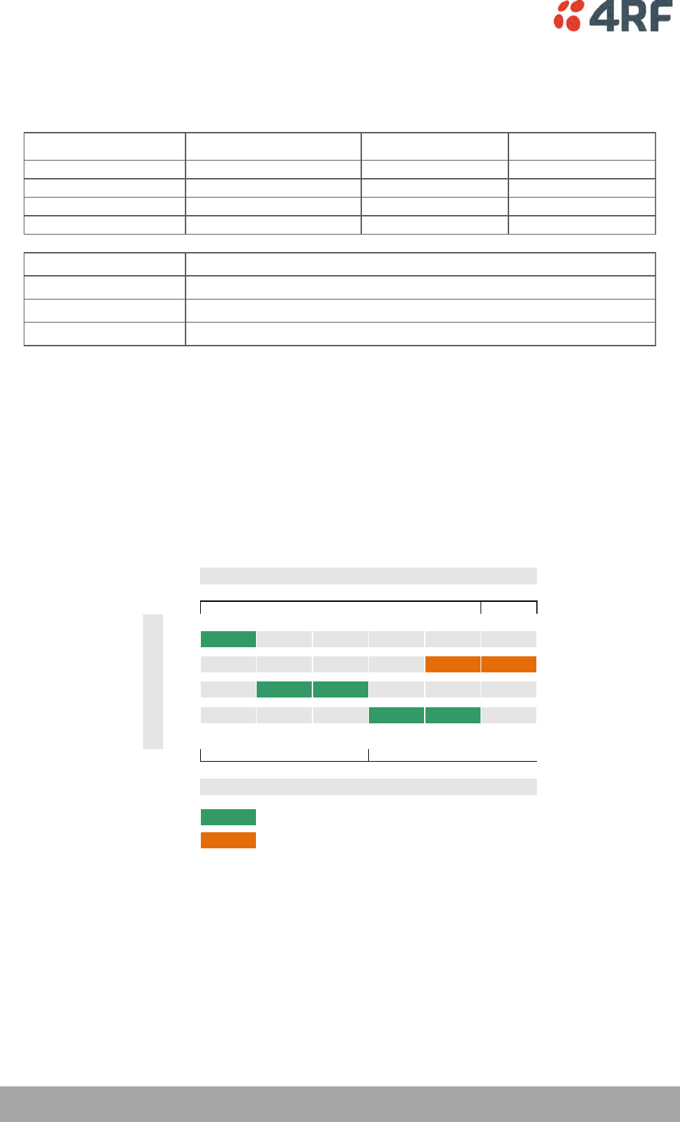
294 | Specifications
Aprisa XE User Manual
FCC
Frequency Bands FCC
Frequency Bands FCC Frequency
Band
Frequency
Tuning Range
Synthesizer
Step Size
400 MHz 421 - 512 MHz 6.25 kHz
700 MHz 698 - 806 MHz 12.5 kHz
900 MHz 928 - 960 MHz 12.5 kHz
2500 MHz 2314 - 2350 MHz 62.5 kHz
Modulation
Frequency stability (short term)
Frequency stability (long term)
Antenna connector
Note 1 Frequency bands Contact 4RF for other frequency band options
Note 2 Modulation 128 QAM is unreleased: Please contact 4RF for availability.
Note 3 Frequency stability
Short term frequency stability is defined as changes in frequency due to environmental effects and power supply variations
Long term frequency stability is defined as changes in frequency due to aging of crystal oscillators approx over 5 years
16 / 32 / 64 / 128 QAM and QPSK (software configurable)
< ±2 ppm
N-type female 50 Ω
< ±1 ppm
Product Range FCC
The Aprisa XE terminal provides the following FCC frequency bands / channel sizes:
MHz
25 100 200 250 500 1.00
400 Part 90
700 Part 27 Part 27
900 Part 101 Part 101
2500 Part 27 Part 27
88 424 952 1.24 2.39 4.98
Mbit/s
Promoted
Product Release Pending
Frequency Band MHz
kHz
Channel Size
kbit/s
Transport capacity @ 64 QAM

Specifications | 295
Aprisa XE User Manual
Link Capacity FCC
Channel size QPSK 16 QAM 32 QAM 64 QAM 128 QAM
25 kHz Gross 56 kbit/s 72 kbit/s 88 kbit/s 104 kbit/s
T1 0 timeslots 1 timeslot 1 timeslot 1 timeslot
Wayside 56 kbit/s 8 kbit/s 24 kbit/s 40 kbit/s
100 kHz Gross 136 kbit/s 280 kbit/s 352 kbit/s 424 kbit/s 608 kbit/s
T1 2 timeslots 4 timeslots 5 timeslots 6 timeslots 9 timeslots
Wayside 8 kbit/s 24 kbit/s 32 kbit/s 40 kbit/s 32 kbit/s
200 kHz Gross 312 kbit/s 632 kbit/s 792 kbit/s 952 kbit/s 1112 kbit/s
T1 4 timeslots 9 timeslots 12 timeslots 14 timeslots 17 timeslots
Wayside 56 kbit/s 56 kbit/s 24 kbit/s 56 kbit/s 24 kbit/s
250 kHz Gross 408 kbit/s 824 kbit/s 1032 kbit/s 1240 kbit/s 1448 kbit/s
T1 6 timeslots 12 timeslots 16 timeslots 19 timeslots 22 timeslots
Wayside 24 kbit/s 56 kbit/s 8 kbit/s 24 kbit/s 40 kbit/s
500 kHz Gross 792 kbit/s 1592 kbit/s 1992 kbit/s 2392 kbit/s 2792 kbit/s
T1 12 timeslots 1 T1 1 T1 1 T1 1 T1
Wayside 24 kbit/s 8 kbit/s 408 kbit/s 808 kbit/s 1208 kbit/s
1.0 MHz Gross 1656 kbit/s 3320 kbit/s 4152 kbit/s 4984 kbit/s 5816 kbit/s
T1 1 T1 2 T1s 2 T1s 3 T1s 3 T1s
Wayside 72 kbit/s 152 kbit/s 984 kbit/s 232 kbit/s 1064 kbit/s
Notes The capacities specified are for Unframed T1 and so require 1584 kbit/s to transport via the radio.
The management ethernet capacity must be subtracted from the gross capacity (default 64 kbit/s).
See Product Range table for Channel Size / Frequency Band cross reference
Receiver Sensitivity FCC
Channel Size QPSK 16 QAM 32 QAM 64 QAM 128 QAM
25 kHz NA -105 dBm -102 dBm -99 dBm -96 dBm
100 kHz -106 dBm -100 dBm -97 dBm -94 dBm -91 dBm
200 kHz -102 dBm -96 dBm -93 dBm -90 dBm -87 dBm
250 kHz -101 dBm -95 dBm -92 dBm -89 dBm -86 dBm
500 kHz -99 dBm -93 dBm -90 dBm -87 dBm -84 dBm
1.0 MHz -96 dBm -90 dBm -87 dBm -84 dBm -81 dBm
Notes
Typical performance specified at the antenna port for 10-6 BER.
The receiver is typically 1 dB more sensitive for a BER of 10-3.
Transmit Power FCC
Frequency Band QPSK 16 QAM 32 QAM 64 QAM 128 QAM
400 MHz NA 17 to 31 dBm 16 to 30 dBm 15 to 29 dBm 15 to 29 dBm
700 MHz 21 to 35 dBm 17 to 31 dBm 16 to 30 dBm 15 to 29 dBm 15 to 29 dBm
900 MHz 15 to 29 dBm 15 to 29 dBm 15 to 29 dBm 15 to 29 dBm 15 to 29 dBm
2500 MHz 15 to 29 dBm 15 to 29 dBm 15 to 29 dBm 15 to 29 dBm 15 to 29 dBm
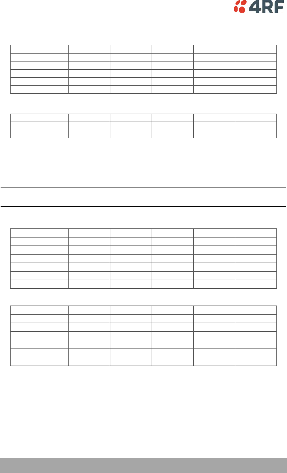
296 | Specifications
Aprisa XE User Manual
System Gain FCC
400 MHz, 700 MHz, 900 MHz
Channel Size QPSK 16 QAM 32 QAM 64 QAM 128 QAM
25 kHz NA 136 dB 132 dB 128 dB 125 dB
100 kHz 135 dB 129 dB 126 dB 123 dB 120 dB
200 kHz 131 dB 125 dB 122 dB 119 dB 116 dB
500 kHz 134 dB 124 dB 120 dB 116 dB 113 dB
1.0 MHz 131 dB 121 dB 117 dB 113 dB 110 dB
2500 MHz
QPSK 16 QAM 32 QAM 64 QAM 128 QAM
250 kHz 130 dB 124 dB 121 dB 118 dB 115 dB
500 kHz 128 dB 122 dB 119 dB 116 dB 113 dB
Notes
Typical performance specified at the antenna port for 10-6 BER.
The system gain is typically 1 dB greater for a BER of 10-3.
System Gain = maximum transmit power - receiver sensitivity
Link Delays FCC
Note: The default Modem Interleaver Mode setting is on for channel sizes of 250 kHz and greater and off
for channel sizes of 200 kHz and less (see ‘Modem Interleaver Mode’ on page 72).
Interleaver off
Channel size QPSK 16 QAM 32 QAM 64 QAM 128 QAM
25 kHz NA 64.4 ms 52.3 ms 44.2 ms 38.5 ms
100 kHz 28.8 ms 15.3 ms 12.7 ms 10.9 ms 8.2 ms
200 kHz 15.9 ms 8.8 ms 7.3 ms 6.4 ms 5.1 ms
250 kHz 11.2 ms 6.6 ms 5.4 ms 5.0 ms 4.2 ms
500 kHz 5.9 ms 3.5 ms 3.4 ms 3.2 ms 2.8 ms
1.0 MHz 3.8 ms 2.6 ms 2.3 ms 2.2 ms 2.1 ms
Interleaver on
Channel size QPSK 16 QAM 32 QAM 64 QAM 128 QAM
25 kHz NA 191.6 ms 154.1 ms 129.1 ms 111.2 ms
100 kHz 85.3 ms 43.6 ms 35.3 ms 29.7 ms 21.4 ms
200 kHz 45.8 ms 23.7 ms 19.3 ms 16.4 ms 12.3 ms
250 kHz 33.2 ms 17.5 ms 14.3 ms 12.1 ms 9.8 ms
500 kHz 17.5 ms 9.3 ms 8.0 ms 6.9 ms 5.7 ms
1.0 MHz 8.8 ms 5.1 ms 4.3 ms 3.9 ms 3.5 ms
Notes The end to end link delays are measured from E1 / T1 interface to E1 / T1 interface
The delay figures are typical and can vary when the system re-synchronizes
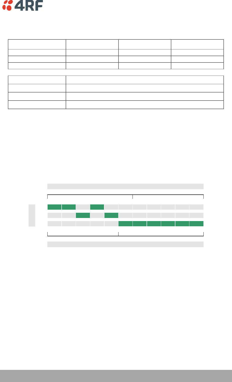
Specifications | 297
Aprisa XE User Manual
Industry Canada
Frequency Bands IC
Frequency Bands IC Frequency
Band
Frequency
Tuning Range
Synthesizer
Step Size
400 MHz 400 - 470 MHz 6.25 kHz
900 MHz 928 - 960 MHz 12.5 kHz
2000 MHz 1900 - 2300 MHz 62.5 kHz
Modulation
Frequency stability (short term)
Frequency stability (long term)
Antenna connector
Note 1 Frequency bands Contact 4RF for other frequency band options
Note 2 Modulation 128 QAM is unreleased: Please contact 4RF for availability.
Note 3 Frequency stability
Short term frequency stability is defined as changes in frequency due to environmental effects and power supply
variations
Long term frequency stability is defined as changes in frequency due to aging of crystal oscillators approx over 5
years
< ±1 ppm
16 / 32 / 64 / 128 QAM and QPSK (software configurable)
< ±2 ppm
N-type female 50 Ω
Product Range IC
The Aprisa XE terminal provides the following Industry Canada frequency bands / channel sizes:
25 75 100 150 200 500 1.00 1.75 3.50 7.00 14.00
400
900
2000
88 400 424 808 952 2.39 4.89 8.63 17.18 35.51 65.46
Freq Band
Channel Size
Transport capacity @ 64 QAM
kHz
MHz
kbit/s
Mbit/s
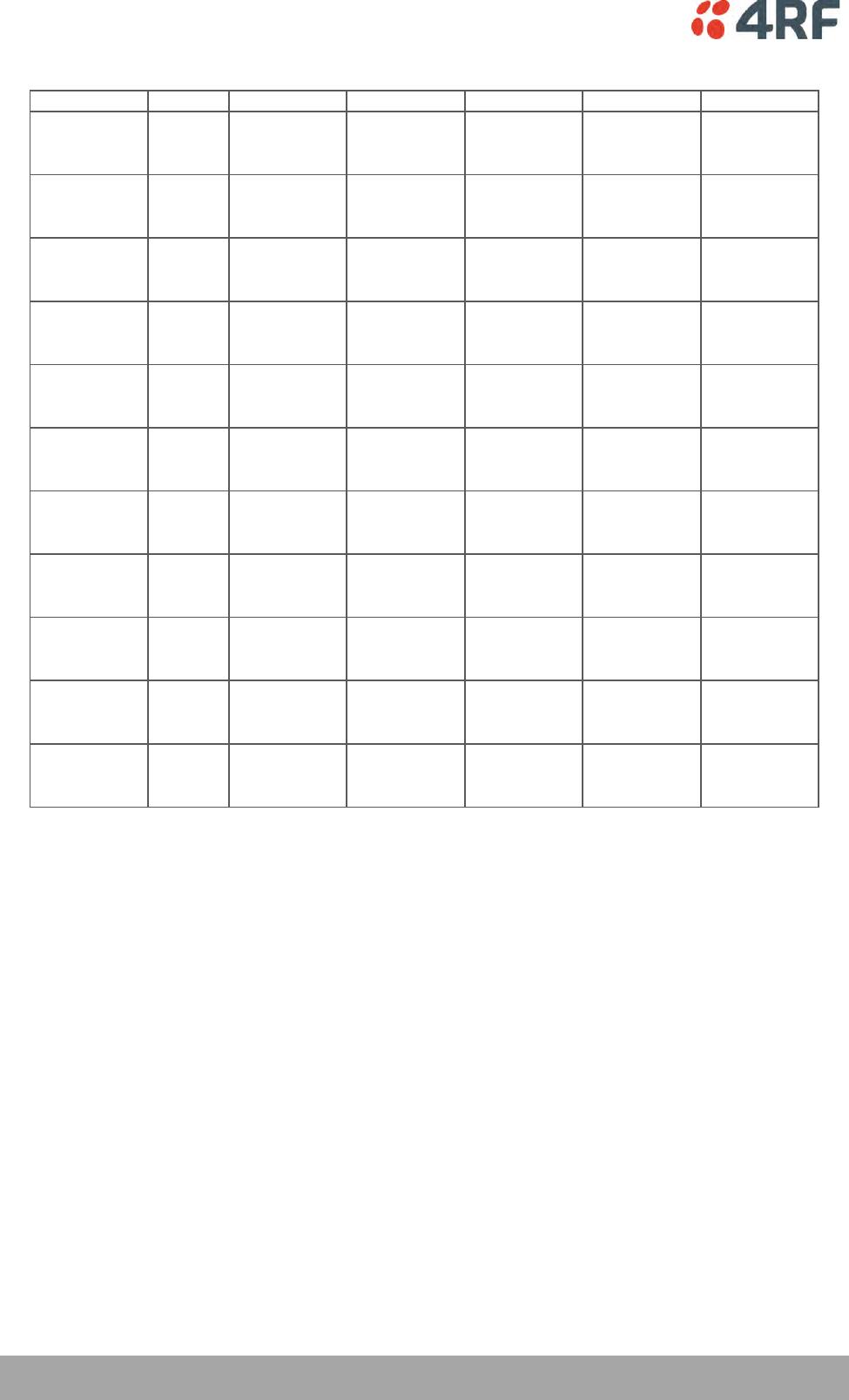
298 | Specifications
Aprisa XE User Manual
Link Capacity IC
Channel size QPSK 16 QAM 32 QAM 64 QAM 128 QAM
25 kHz Gross NA 56 kbit/s 72 kbit/s 88 kbit/s NA
T1 0 timeslots 1 timeslot 1 timeslot
Wayside 56 kbit/s 8 kbit/s 24 kbit/s
75 kHz Gross 128 kbit/s 264 kbit/s 312 kbit/s 400 kbit/s 440 kbit/s
T1 2 timeslots 4 timeslots 4 timeslots 6 timeslots 6 timeslots
Wayside 0 kbit/s 8 kbit/s 56 kbit/s 16 kbit/s 56 kbit/s
100 kHz Gross 136 kbit/s 280 kbit/s 352 kbit/s 424 kbit/s 608 kbit/s
T1 2 timeslots 4 timeslots 5 timeslots 6 timeslots 9 timeslots
Wayside 8 kbit/s 24 kbit/s 32 kbit/s 40 kbit/s 32 kbit/s
150 kHz Gross 264 kbit/s 536 kbit/s 672 kbit/s 808 kbit/s 944 kbit/s
T1 4 timeslots 8 timeslots 10 timeslots 12 timeslots 14 timeslots
Wayside 8 kbit/s 24 kbit/s 32 kbit/s 40 kbit/s 48 kbit/s
200 kHz Gross 312 kbit/s 632 kbit/s 792 kbit/s 952 kbit/s 1112 kbit/s
T1 4 timeslots 9 timeslots 12 timeslots 14 timeslots 17 timeslots
Wayside 56 kbit/s 56 kbit/s 24 kbit/s 56 kbit/s 24 kbit/s
500 kHz Gross 792 kbit/s 1592 kbit/s 1992 kbit/s 2392 kbit/s 2792 kbit/s
T1 12 timeslots 1 T1 1 T1 1 T1 1 T1
Wayside 24 kbit/s 8 kbit/s 408 kbit/s 808 kbit/s 1208 kbit/s
1.0 MHz Gross 1624 kbit/s 3256 kbit/s 4072 kbit/s 4888 kbit/s 5704 kbit/s
T1 1 T1 2 T1s 2 T1s 3 T1s 3 T1s
Wayside 40 kbit/s 88 kbit/s 904 kbit/s 136 kbit/s 952 kbit/s
1.75 MHz Gross 2872 kbit/s 5752 kbit/s 7192 kbit/s 8632 kbit/s 10072 kbit/s
T1 1 T1 3 T1s 4 T1s 5 T1s 6 T1s
Wayside 1288 kbit/s 1000 kbit/s 856 kbit/s 712 kbit/s 568 kbit/s
3.5 MHz Gross 5720 kbit/s 11448 kbit/s 14312 kbit/s 17176 kbit/s 20040 kbit/s
T1 3 T1s 7 T1s 9 T1s 10 T1s 12 T1s
Wayside 968 kbit/s 360 kbit/s 56 kbit/s 1336 kbit/s 1032 kbit/s
7.0 MHz Gross 11832 kbit/s 23672 kbit/s 29592 kbit/s 35512 kbit/s 41432 kbit/s
T1 7 T1s 14 T1s 18 T1s 22 T1s 26 T1s
Wayside 744 kbit/s 1496 kbit/s 1080 kbit/s 664 kbit/s 248 kbit/s
14 MHz Gross NA 47992 kbit/s 59992 kbit/s 65464 kbit/s 65400 kbit/s
T1 30 T1s 32 T1s 32 T1s 32 T1s
Wayside 472 kbit/s 9304 kbit/s 14776 kbit/s 14712 kbit/s
Notes The capacities specified are for Unframed T1 and so require 1584 kbit/s to transport via the radio.
The management ethernet capacity must be subtracted from the gross capacity (default 64 kbit/s).
See Product Range table for Channel Size / Frequency Band cross reference
NA (Not Available)
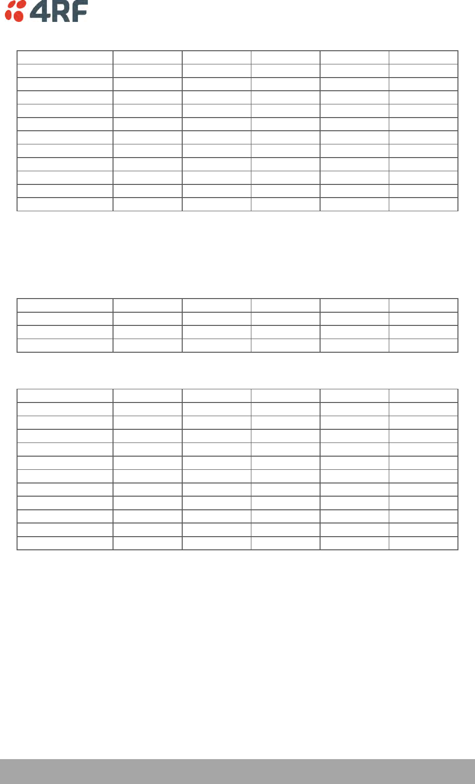
Specifications | 299
Aprisa XE User Manual
Receiver Sensitivity IC
Channel size QPSK 16 QAM 32 QAM 64 QAM 128 QAM
25 kHz NA -105 dBm -102 dBm -99 dBm NA
75 kHz -107 dBm -101 dBm -98 dBm -95 dBm -92 dBm
100 kHz -106 dBm -100 dBm -97 dBm -94 dBm -91 dBm
150 kHz -104 dBm -98 dBm -95 dBm -92 dBm -89 dBm
200 kHz -102 dBm -96 dBm -93 dBm -90 dBm -87 dBm
500 kHz -99 dBm -93 dBm -90 dBm -87 dBm -84 dBm
1.0 MHz -96 dBm -90 dBm -87 dBm -84 dBm -81 dBm
1.75 MHz -94 dBm -88 dBm -85 dBm -82 dBm -79 dBm
3.5 MHz -90 dBm -84 dBm -81 dBm -78 dBm -75 dBm
7.0 MHz -87 dBm -81 dBm -78 dBm -75 dBm -72 dBm
14 MHz NA -78 dBm -75 dBm -72 dBm -69 dBm
Notes
Typical performance specified at the antenna port for 10-6 BER.
The receiver is typically 1 dB more sensitive for a BER of 10-3.
NA (Not Available)
Transmitter Power IC
Frequency Band QPSK 16 QAM 32 QAM 64 QAM 128 QAM
400 MHz 15 to 35 dBm 15 to 31 dBm 15 to 30 dBm 15 to 29 dBm 15 to 29 dBm
900 MHz 15 to 29 dBm 15 to 29 dBm 15 to 29 dBm 15 to 29 dBm 15 to 29 dBm
2000 MHz 20 to 34 dBm 17 to 31 dBm 16 to 30 dBm 15 to 29 dBm 15 to 29 dBm
System Gain IC
Channel Size QPSK 16 QAM 32 QAM 64 QAM 128 QAM
25 kHz NA 136 dB 132 dB 128 dB NA
75 kHz 142 dB 132 dB 128 dB 124 dB 121 dB
100 kHz 135 dB 129 dB 126 dB 123 dB 120 dB
150 kHz 139 dB 129 dB 125 dB 121 dB 118 dB
200 kHz 131 dB 125 dB 122 dB 119 dB 116 dB
500 kHz 133 dB 124 dB 120 dB 116 dB 113 dB
1.0 MHz 130 dB 121 dB 117 dB 113 dB 110 dB
1.75 MHz 128 dB 119 dB 115 dB 111 dB 108 dB
3.5 MHz 124 dB 115 dB 111 dB 107 dB 104 dB
7.0 MHz 121 dB 112 dB 108 dB 104 dB 101 dB
14 MHz NA 109 dB 105 dB 101 dB 98 dB
Notes
Typical performance specified at the antenna port for 10-6 BER.
The system gain is typically 1 dB greater for a BER of 10-3.
System Gain = maximum transmit power - receiver sensitivity
NA (Not Available)
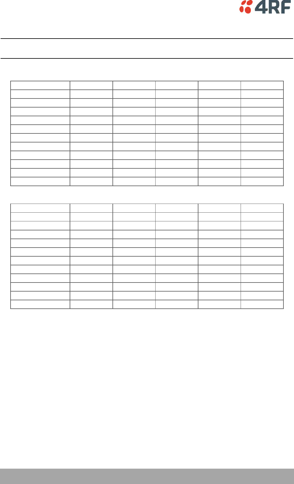
300 | Specifications
Aprisa XE User Manual
Link Delays IC
Note: The default Modem Interleaver Mode setting is on for channel sizes of 250 kHz and greater and off
for channel sizes of 200 kHz and less (see ‘Modem Interleaver Mode’ on page 72).
Interleaver off
Channel size QPSK 16 QAM 32 QAM 64 QAM 128 QAM
25 kHz NA 49.6 ms 39.4 ms 34.9 ms NA
75 kHz 35.5 ms 19.0 ms 16.8 ms 13.6 ms 10.6 ms
100 kHz 28.8 ms 15.3 ms 12.7 ms 10.9 ms 8.2 ms
150 kHz 17.5 ms 10.1 ms 8.5 ms 7.1 ms 5.7 ms
200 kHz 15.9 ms 8.8 ms 7.3 ms 6.4 ms 5.1 ms
500 kHz 6.3 ms 3.5 ms 3.4 ms 3.2 ms 2.8 ms
1.0 MHz 3.8 ms 2.6 ms 2.3 ms 2.2 ms 2.1 ms
1.75 MHz 3.1 ms 2.3 ms 2.1 ms 2.0 ms 1.9 ms
3.5 MHz 2.6 ms 2.0 ms 1.8 ms 1.8 ms 1.7 ms
7.0 MHz 2.0 ms 1.7 ms 1.6 ms 1.6 ms 1.6 ms
14 MHz NA 1.6 ms 1.5 ms 1.5 ms 1.5 ms
Interleaver on
Channel size QPSK 16 QAM 32 QAM 64 QAM 128 QAM
25 kHz NA 164.7 ms 127.7 ms 111.8 ms NA
75 kHz 103.7 ms 53.2 ms 45.8 ms 36.4 ms 28.8 ms
100 kHz 85.3 ms 43.6 ms 35.3 ms 29.7 ms 21.4 ms
150 kHz 51.4 ms 26.8 ms 21.9 ms 18.6 ms 14.3 ms
200 kHz 45.8 ms 23.7 ms 19.3 ms 16.4 ms 12.3 ms
500 kHz 16.5 ms 9.3 ms 8.0 ms 6.9 ms 5.7 ms
1.0 MHz 8.8 ms 5.1 ms 4.3 ms 3.9 ms 3.5 ms
1.75 MHz 6.8 ms 4.1 ms 3.6 ms 3.2 ms 2.9 ms
3.5 MHz 5.1 ms 3.2 ms 2.8 ms 2.6 ms 2.4 ms
7.0 MHz 3.5 ms 2.4 ms 2.2 ms 2.1 ms 2.0 ms
14 MHz NA 2.1 ms 1.9 ms 1.8 ms 1.8 ms
Notes The end to end link delays are measured from E1 / T1 interface to E1 / T1 interface
The delay figures are typical and can vary when the system re-synchronizes
NA (Not Available)
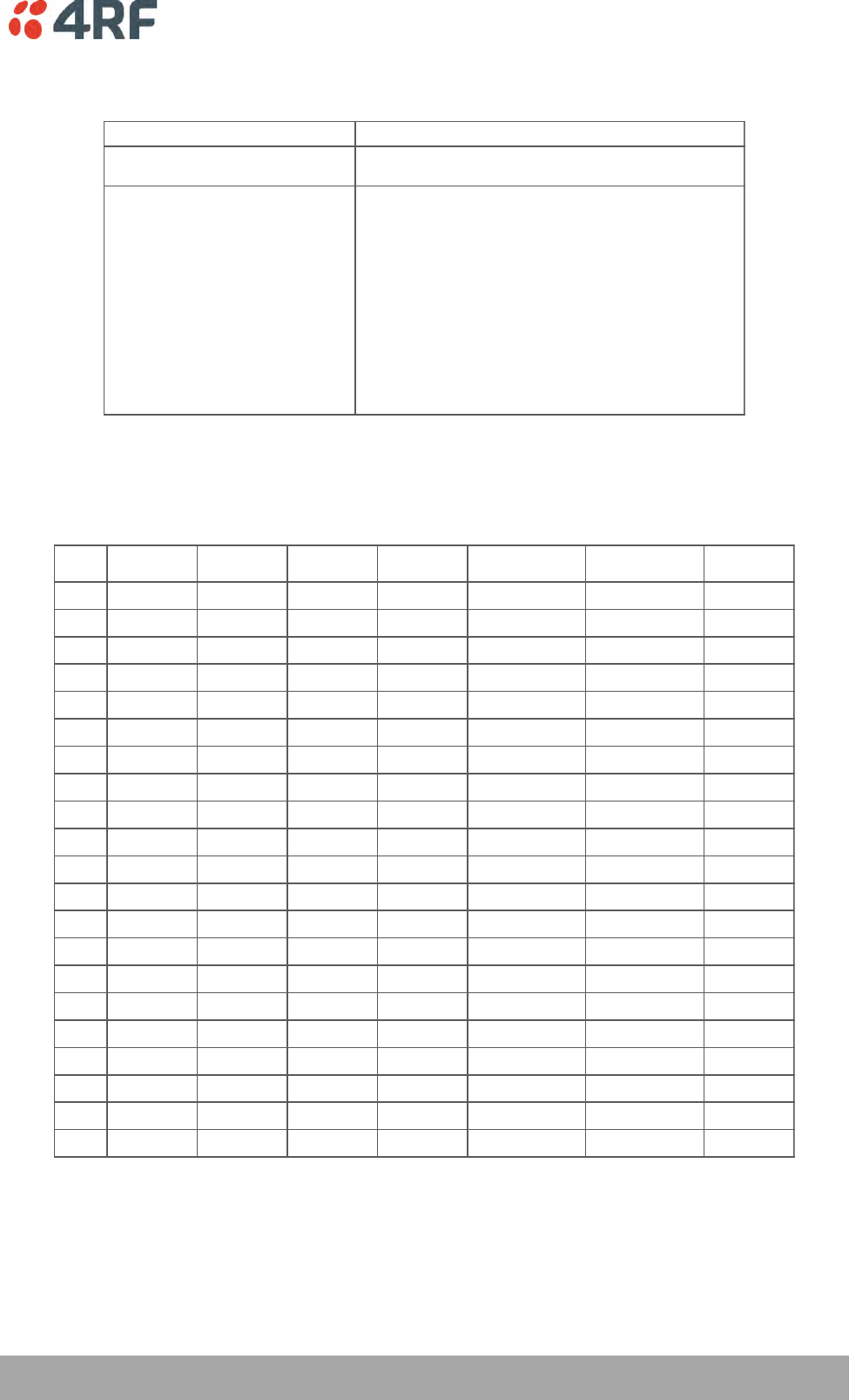
Specifications | 301
Aprisa XE User Manual
Receiver Performance
-20 dBm
58 to 87 dB (at 10-6 BER)
depending on modulation type and channel size
C/I ratio = CdB - IdB
Co-channel better than 16 dB at QPSK
better than 20 dB at 16 QAM
better than 23 dB at 32 QAM
better than 27 dB at 64 QAM
better than 30 dB at 128 QAM
1st adjacent channel better than -5 dB
2nd adjacent channel better than -30 dB
Notes
Typical performance specified at the antenna port for 10-6 BER.
The dynamic range is typically 2 dB greater for a BER of 10-3.
Maximum input level
Dynamic range
C/I ratio
(carrier to interference ratio)
Duplexers
Code
Frequency
Band
Option
TX / RX
Min Split
Passband Lo Band Hi Band Mounting
A0 300 MHz Standard 9.45 MHz 2 MHz 330 - 400 MHz 330 - 400 MHz External
A1 300 MHz Option 1 5 MHz 0.5 MHz 330 - 400 MHz 330 - 400 MHz External
A2 300 MHz Option 2 20 MHz 3.5 MHz 330 - 400 MHz 330 - 400 MHz External
B0 400 MHz Standard 9.45 MHz 2 MHz 400 - 470 MHz 400 - 470 MHz External
B1 400 MHz Option 1 5 MHz 0.5 MHz 400 - 470 MHz 400 - 470 MHz External
B2 400 MHz Option 2 20 MHz 3.5 MHz 400 - 470 MHz 400 - 470 MHz External
C0 400 MHz Standard 3 MHz 0.5 MHz 470 - 492 MHz 473 - 495 MHz External
D0 600 MHz Standard 45 MHz 7 MHz 620 - 715 MHz 620 - 715 MHz Internal
E0 700 MHz Standard 30 MHz 7 MHz 698 - 806 MHz 698 - 806 MHz Internal
F0 800 MHz Standard 40 MHz 7 MHz 805 - 890 MHz 805 - 890 MHz Internal
G0 900 MHz Standard 40 MHz 7 MHz 850 - 960 MHz 850 - 960 MHz Internal
G1 900 MHz Option 1 9 MHz 1.5 MHz 928 - 960 MHz 928 - 960 MHz External
G2 900 MHz Option 2 9 MHz 1 MHz 928 - 960 MHz 928 - 960 MHz Internal
G3 900 MHz Option 3 5.5 MHz 0.5 MHz 900 - 960 MHz 900 - 960 MHz External
G4 900 MHz Option 4 3.6 MHz 0.5 MHz 900 - 960 MHz 900 - 960 MHz External
H0 1400 MHz Standard 48 MHz 7 MHz 1350 - 1550 MHz 1350 - 1550 MHz Internal
H1 1400 MHz Option 1 23.5 MHz 7 MHz 1350 - 1550 MHz 1350 - 1550 MHz Internal
K0 1800 MHz Standard 47.5 MHz 14 MHz 1700 - 2100 MHz 1700 - 2100 MHz Internal
I0 2000 MHz Standard 91 MHz 14 MHz 1900 - 2300 MHz 1900 - 2300 MHz Internal
J0 2500 MHz Standard 74 MHz 14 MHz 2300 - 2700 MHz 2300 - 2700 MHz Internal
J1 2500 MHz Option 1 32 MHz 4 MHz 2314 - 2318 MHz 2346 - 2350 MHz Internal
Notes All duplexers are bandpass
Contact 4RF for other duplexer options
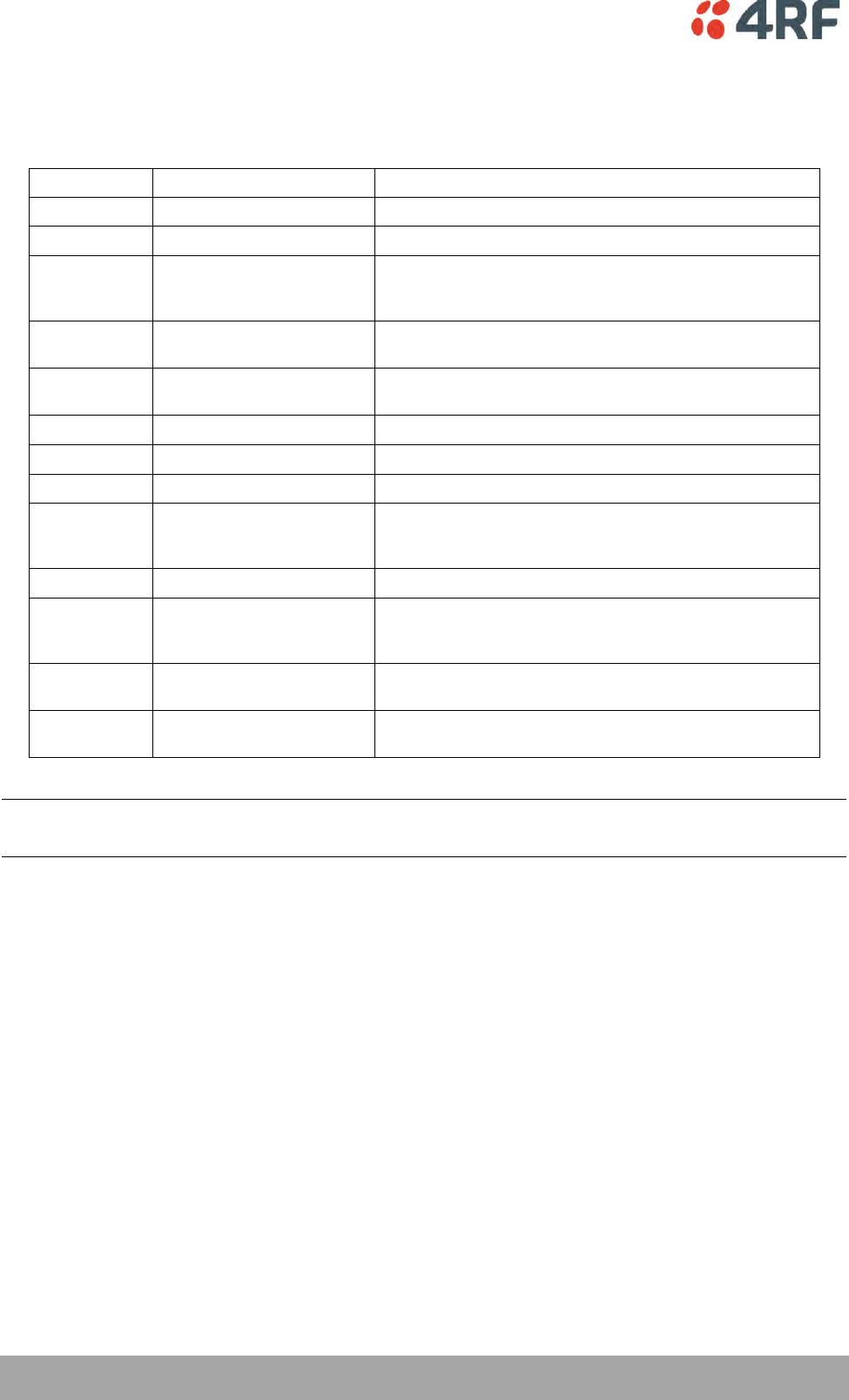
302 | Specifications
Aprisa XE User Manual
Interface Specifications
Ethernet Interface
General
Interface
RJ-45 * 4 (Integrated 4-port switch)
Cabling
CAT-5 UTP, supports auto MDIX (Standard Ethernet)
Maximum line length
100 metres on cat-5 or better
Bandwidth allocation
n x 8 kbit/s up to maximum available.
n x 64 kbit/s is recommended for terminals with higher
channel size (> 500 kHz, 32 QAM).
Ethernet capacity
The ethernet capacity maximum is determined by the lesser
of the available radio link capacity or 50 Mbit/s.
Maximum packet size
‘Standard’ Ethernet packets: max 1518 octets
Tagged and double-tagged packets: max 1526 octets
Data buffer size
Up to 256 frames
Address table size
2048 IP addresses
WAN protocol
HDLC
Ethernet mode
10Base-T or 100Base-TX
Full duplex or half duplex
(Auto-negotiating and auto-sensing)
VLAN tagging
IEEE 802.1Q VLAN tagging
QoS
IEEE 802.1p
Ipv4 TOS DiffServ
Ipv6 traffic class
Spanning Tree
Forwards 802.1D Spanning Tree Protocol packets up to 1526
bytes in length.
Diagnostics
Green LED
On: Ethernet signal received
Flashing: Indicates data traffic present on the interface
Note: Do not connect Power over Ethernet (PoE) connections to the Aprisa XE Ethernet ports as this will
damage the port.
Specifications | 303
Aprisa XE User Manual
QJET Quad E1 / T1 Interface
General
Standard
G.703 and G.704
Interface
RJ-45
Line termination impedance
E1 120 Ω balanced
T1 100 Ω balanced
Maximum line length
E1 typically up to 1.7 km (43 dB of loss at 1024 kHz in
standard 0.4 mm2 cable).
T1 typically up to 1.7 km (36 dB of loss at 772 kHz in
standard 0.4 mm2 cable).
Bandwidth allocation
Framed E1s require a link bandwidth of 2048 kbit/s.
Unframed E1s require a link bandwidth of 2088 kbit/s.
Framed T1s require a link bandwidth of 1544 kbit/s.
Unframed T1s require a link bandwidth of 1584 kbit/s.
Line code
E1 HDB3 or AMI
T1 B8ZS or AMI
Tx Waveform Shaper
(T1 only)
0 ~ 133 ft
133 ~ 266 ft
266 ~ 399 ft
399 ~ 533 ft
533 ~ 655 ft
Stability
±50 ppm
Jitter performance
G.823 (sections 2 & 3)
Diagnostics
Green LED
On: Interface is operational and in service
Off: No 2 Mbit/s input signal
Flashing: The interface loopback is active.
Yellow LED
On: Alarm
Off: No alarm

304 | Specifications
Aprisa XE User Manual
Q4EM Quad 4 Wire E&M Interface
General
Audio
64 kbit/s (PCM A-Law as per ITU G.711)
32, 24 and 16 kbit/s (ADPCM as per ITU G.726 and ANSI
TI.303)
E&M signalling
8 kbit/s per port
Maximum line length
400 metres
Analogue
Transmission performance
characteristics
ITU G.712 E4 for an operating level range of -14 dBr to
+4 dBr for a G.711 64 kbit/s coded channel
Input level range
-14.0 dBr to +4.0 dBr in 0.5 dB steps
Output level range
-14.0 dBr to +4.0 dBr in 0.5 dB steps
Default output level
0 dBr
Default input level
0 dBr
Maximum level
+3.14 dBm0
Port impedance
600 Ω
Return loss
better than 25 dB over the frequency range 200 - 3600 Hz
Transformer isolation
3.88 kV
End to end gain
Frequency response
0 dB ± 0.1 dB (300-3000 Hz)
0 dB ± 0.5 dB (250-3400 Hz)
Audio line protection
Secondary protection
Signal to total distortion
> 30 dB (0 dBm0 to -30 dBm0)
> 22 dB (-45 dBm0)
Signalling
E&M
Mode independent (external power supply / ground
reference required)
Pulse distortion
4:1 multiplexed < 2.250 ms
Non-multiplexed 250 µs
M loop current
5.0 to 6.5 mA (constant current)
M detection voltage
9 VDC
M maximum voltage
60 VDC
E circuit impedance
45 Ω closed
> 100 kΩ open
Maximum E circuit current
100 mA
E maximum voltage
60 V
E&M circuit protection
E: Current limited to 120 mA, overvoltage to 350 V
M: Current limited to 6.5 mA, overvoltage to 100 V
Diagnostics
Green LED
Off: No external source applied to M wire
On: External source applied to M wire
Flashing: The interface loopback is active
Yellow LED
Off: E wire relay contact open
On: E wire relay contact closed

Specifications | 305
Aprisa XE User Manual
DFXO Dual Foreign Exchange Office Interface
General
Audio
64 kbit/s (PCM as per ITU G.711)
32, 24 and 16 kbit/s (ADPCM as per ITU G.726 and ANSI
TI.303)
Signalling allocation
8 or 32 kbit/s allocated for CAS (multiplexed / non
multiplexed)
Companding
A-Law or µ-Law
Maximum line length
600 metres (2000 feet) on 0.4 mm / 26 AWG copper pair
Calling line ID (CLI)
Support provided for ETSI: EN 300 659-1 & 2 and BT: SIN 227
and 242
Fax
Conforms to G3 standard for 64 kbit/s PCM and 32 kbit/s
ADPCM compression
Analogue
Transmission performance
characteristics
ITU G.712 E2 for an operating level range of -6 dBr to +1 dBr
for a G.711 64 kbit/s coded channel
Input level range
-10 dBr to +1.0 dBr in 0.5 dB steps
Output level range
-10 dBr to +1.0 dBr in 0.5 dB steps
Default Input level
-4.0 dBr
Default Output level
-1.0 dBr
Maximum level
+3.14 dBm0
Line impedance / Hybrid
balance impedance options
600 Ω
900 Ω
600 Ω + 2.16 µF
900 Ω + 2.16 µF
270 Ω + 750 Ω || 150 nF (TBR-21)
220 Ω + 820 Ω || 120 nF (TN12)
370 Ω + 620 Ω || 310 nF (BT3)
320 Ω + 1050 Ω || 210 nF (BT Network)
200 Ω + 680 Ω || 100 nF (China)
Return Loss
better than 12 dB 300 Hz to 600 Hz
better than 15 dB 600 Hz to 3400 Hz
Trans hybrid loss
better than 13 dB 300 Hz to 3400 Hz
better than 17 dB 500 Hz to 2500 Hz
(with matched external line and hybrid balance impedance)
Common mode rejection
ratio
better than 40 dB 50 Hz to 3800 Hz
better than 46 dB 600 Hz to 3400 Hz
Echo Canceller
provides up to 64 ms of echo cancellation
reduces the echo by more than 15 dB at an input signal level
of 10 dBm0.
306 | Specifications
Aprisa XE User Manual
Signalling
DTMF dialing
Standard DTMF dialing over the voice channel
Pulse dialing
Transparent decadic signalling at 7 - 14 PPS with break
period limits of 60 - 73 %
Pulse distortion
4:1 multiplexed < 2.250 ms
Non-multiplexed 250 µs
Reversals
Line polarity reversal detection
Loop current limit
maximum of 60 mA with Loop Current Limiter On
maximum of 160 mA with Loop Current Limiter Off
Metering level sensitivity
12 kHz / 16 kHz billing tone detection with a selectable
level sensitivity of -17dBm to -40 dBm in 1dB steps into 200
Ω
(60 mV rms to 5 mV rms into 200 Ω).
Metering level maximum
The maximum level of metering signal the DFXO can tolerate
without voice band interference is 0.8 Vrms into 200 Ω.
Loop resistance on-hook
>1 MΩ
Ringing detection threshold
Three selectable options of 16 Vrms, 26 Vrms and 49 Vrms ±
20 %.
Ringing detection frequency
15 to 50 Hz sine wave
Ringing input impedance
Two selectable options of >1 MΩ and >12 kΩ
Ringing DC offset range
tolerance
0 to -75VDC
Ringing input voltage
maximum
up to 100 Vrms
Ringing cadence limits
min max
Ringing ON: 270 ms 10 secs
Ringing OFF: 180 ms 4 secs
Ringing cadence distortion
< 40 ms cadence error on both ring and silent periods
Physical
Physical interface
Dual RJ-45 per port (1 line port, 1 monitor port)
Diagnostics
Green LED
Off: Interface operational but not in service
On: Interface in service
Flashing: Cadenced ringing on line
Yellow LED
Off: No interface alarm
On: Interface alarm
Flashing: The interface loopback is active
Specifications | 307
Aprisa XE User Manual
DFXS Dual Foreign Exchange Subscriber Interface
General
Audio
64 kbit/s (PCM as per ITU G.711)
32, 24 and 16 kbit/s (ADPCM as per ITU G.726 and ANSI
TI.303)
Signalling Allocation
8 or 32 kbit/s allocated for CAS (multiplexed / non
multiplexed)
Compression coding
A-Law or µ-Law
Maximum line length
600 metres (2000 feet) on 0.4 mm / 26 AWG copper pair
Calling line ID (CLI)
Support provided for ETSI: EN 300 659-1 & 2 and BT: SIN 227
and 242
Fax
Conforms to G3 standard for 64 kbit/s PCM and 32 kbit/s
ADPCM compression
Analogue
Transmission performance
characteristics
ITU G.712 E2 for an operating level range of -6 dBr to
+2.0 dBr for a G.711 64 kbit/s coded channel
Input level range
-9.0 dBr to +2.0 dBr in 0.5 dB steps
Output level range
-9.5 dBr to +2.5 dBr in 0.5 dB steps
Default Input level
+1.0 dBr
Default Output level
-6.0 dBr
Maximum level
+3.14 dBm0
Line impedance / Hybrid
balance impedance options
600 Ω
900 Ω
600 Ω + 2.16 µF
900 Ω + 2.16 µF
220 Ω + (820 Ω || 120 nF) (TN12)
270 Ω + (750 Ω || 150 nF) (TBR21)
370 Ω + (620 Ω || 310 nF) (BT3)
Return Loss
better than 12 dB 300 Hz to 600 Hz
better than 15 dB 600 Hz to 3400 Hz
Trans hybrid loss
better than 13 dB 300 Hz to 3400 Hz
better than 17 dB 500 Hz to 2500 Hz
(with matched external line and hybrid balance impedance)
Common mode rejection
ratio
better than 40 dB 50 Hz to 3800 Hz
better than 46 dB 600 Hz to 3400 Hz
308 | Specifications
Aprisa XE User Manual
Signalling
Feed voltage output
-48 V (160 + 160 Ω voltage source current limited)
Loop current limit
35 mA ± 10 %.
Seize signal
Loop start only (no ground start)
Loop detect threshold
9 to 12 mA (step function between on hook and off hook)
Loop non-seizure current
> 6 mA (step function between on hook and off hook)
Loop release threshold
> 4 mA
DTMF dialing
Standard DTMF dialing over the voice channel
Pulse dialing
Transparent decadic signalling at 7 - 14 PPS with break
period limits of 60 - 73 % (with loop current > 23 mA)
Pulse distortion
4:1 multiplexed < 2.250 ms
Non-multiplexed 250 µs
Reversals output
Line polarity reversal output (optional)
Metering output frequency
12 kHz / 16 kHz ± 0.5 %.
Metering output voltage
Four selectable output voltages of 100 mV, 200 mV, 300 mV
and 400 mV rms into 200 Ω ± 20 % sourced via the Line
Impedance setting but limited to a maximum open circuit
voltage of 1 Vrms.
Metering output distortion
Billing tone total distortion < 5 %.
Ringer waveform
Sinusoidal with a maximum total distortion of 10% (into 3
REN load)
Ringer voltage (open circuit)
Five selectable ringer output voltages sourced via an
internal ringing resistance of 178 per port.
The ringing output is a composite balanced AC ringing
voltage with a differential DC offset voltage.
60 Vrms + 0 VDC
55 Vrms + 10 VDC
50 Vrms + 18 VDC
45 Vrms + 22 VDC
40 Vrms + 24 VDC
Both the DC and AC components have a tolerance of ± 5%.
Ringer output frequency
Three selectable options of 17, 25 or 50 Hz ± 5%
Ringer output power
60 Vrms source into a load of 2 REN
45 Vrms source into a load of 3 REN
(1 REN 6930 F)
Ring trip
Ring trip will ocurr in < 150 ms following DC loop of > 20 mA
Ring trip immunity
Ring trip will not ocurr if the DFXS outputs ringing into a
load of 500 in series with 4.4 F or less.
Physical
Physical interface
Dual RJ-45 per port (1 line port, 1 monitor port)
Line protection
Secondary protection (4RF recommends the use of external
primary protection in lightning prone areas)
Diagnostics
Green LED
Off: Interface operational but not in service
On: Interface in service
Flashing: Cadenced ringing on line
Yellow LED
Off: No interface alarm
On: Interface alarm
Flashing: The interface loopback is active
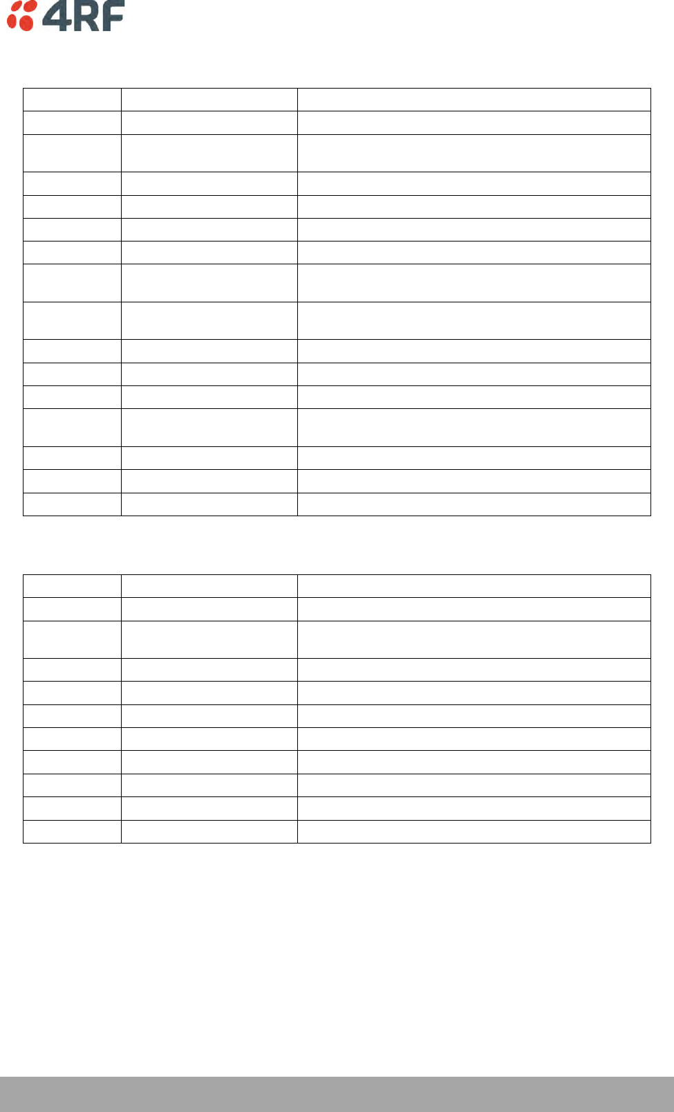
Specifications | 309
Aprisa XE User Manual
QV24 Quad V.24 Serial Data Interface
General
Interface
ITU-T V.24 / EIA/TIA RS-232E
Interface direction
DCE only
Bandwidth allocation
8 to 120 kbit/s in 8 kbit/s steps (dependent on rate
selected)
Control line allocation
8 kbit/s
Maximum line length
10 metres
Data clamp
Mark hold when out of sync.
Control line clamp
Off when loss of sync.
Clock
Internally generated from 2.048 MHz system clock
(synchronized at both ends)
Async
parameters
Transparent mode
Operation is completely transparent but limited to 0-600
bit/s
Standard mode data bits
7 or 8 bits
Standard mode parity
Transparent (enable / disable)
Standard mode stop bits
1 or 2 bits
Asynchronous Data rates
300, 600, 1200, 2400, 4800, 7200, 9600, 12800, 14400,
19200, 23040, 28800, 38400, 57600 and 115200 bit/s
Control signals
End-to-end
CTS to RTS, DSR to DTR
Diagnostics
Green LED
Indicates RX data traffic present
Yellow LED
Indicates TX data traffic present
QV24S Quad V.24 Serial Data Interface
General
Interface
ITU-T V.24 / EIA/TIA RS-232E
Interface direction
DCE only
Bandwidth allocation
8 to 120 kbit/s in 8 kbit/s steps (dependent on rate
selected)
Control line allocation
8 kbit/s
Maximum line length
10 metres
Data clamp
Mark hold when out of sync.
Control line clamp
Off when loss of sync.
Synchronous Data rates
300, 600, 1200, 2400, 4800, 9600 and 19200 bit/s
Control signals
End-to-end
CTS to RTS
Diagnostics
Green LED
Indicates RX data traffic present
Yellow LED
Indicates TX data traffic present
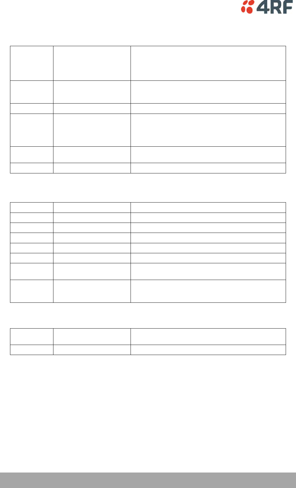
310 | Specifications
Aprisa XE User Manual
HSS Single High Speed Synchronous Data Interface
General
Interfaces
ITU-T V.35
ITU-T X.21
EIA RS-449
EIA RS-530
Bandwidth allocation
8 to 2048 kbit/s in 8 kbit/s steps (dependent on rate
selected)
8 kbit/s for control lines
Maximum line length
3 metres
Clock
Internally generated from 2.048 MHz system clock
(synchronized at both ends) on DCE to DCE mode.
Clock provided by external DCE when in DTE mode.
Remote DCE outputs clock-timed by incoming clock at DTE.
Diagnostics
Top Green LED
On: Normal operation
Flashing: Loopback
Lower Green LED
On: Normal operation
External Alarm Interfaces
Alarm inputs
Detector type
Isolated current detectors
Detection current
5.0 to 6.5 mA (constant current)
Detection voltage
9 to 60 VDC or AC rms
Alarm outputs
Contact type
Isolated semiconductor relay type contacts
Maximum current
100 mA
Maximum voltage
0 to 60 VDC or AC rms
Ouput impedance
45 Ω closed
> 100 kΩ open
Overall
Latency
The latency for an alarm presented on an external alarm
input to the alarm being output on an external alarm output
is < 2 seconds
Auxiliary Interfaces
Management
Configuration and
management
Embedded web server and / or SNMP accessed via Ethernet
interface or across link
Test points
RSSI
Front panel test point for measuring the RSSI voltage
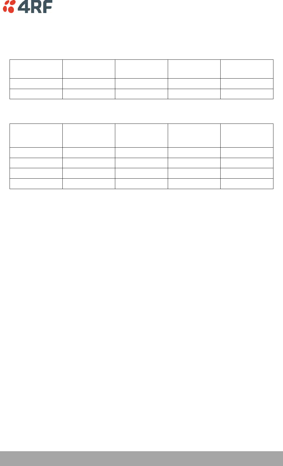
Specifications | 311
Aprisa XE User Manual
Power Specifications
AC Power Supply
Nominal
voltage
Input voltage
range
Maximum Power
input
Max VA
Frequency
115 VAC
103 - 127 Vrms
180 W
400 VA
47 - 63 Hz
230 VAC
207 - 254 Vrms
180 W
400 VA
47 - 63 Hz
DC Power Supply
Nominal voltage
Input voltage
range
Maximum Power
input
Maximum input
current
Recommended
DC breaker
rating
+12 VDC LP
10.5 to 18 VDC
53 W
5 A
8 A
±12 VDC
10.5 to 18 VDC
180 W
18 A
25 A
±24 VDC
20.5 to 30 VDC
180 W
8 A
10 A
±48 VDC
40 to 60 VDC
180 W
4 A
5 A
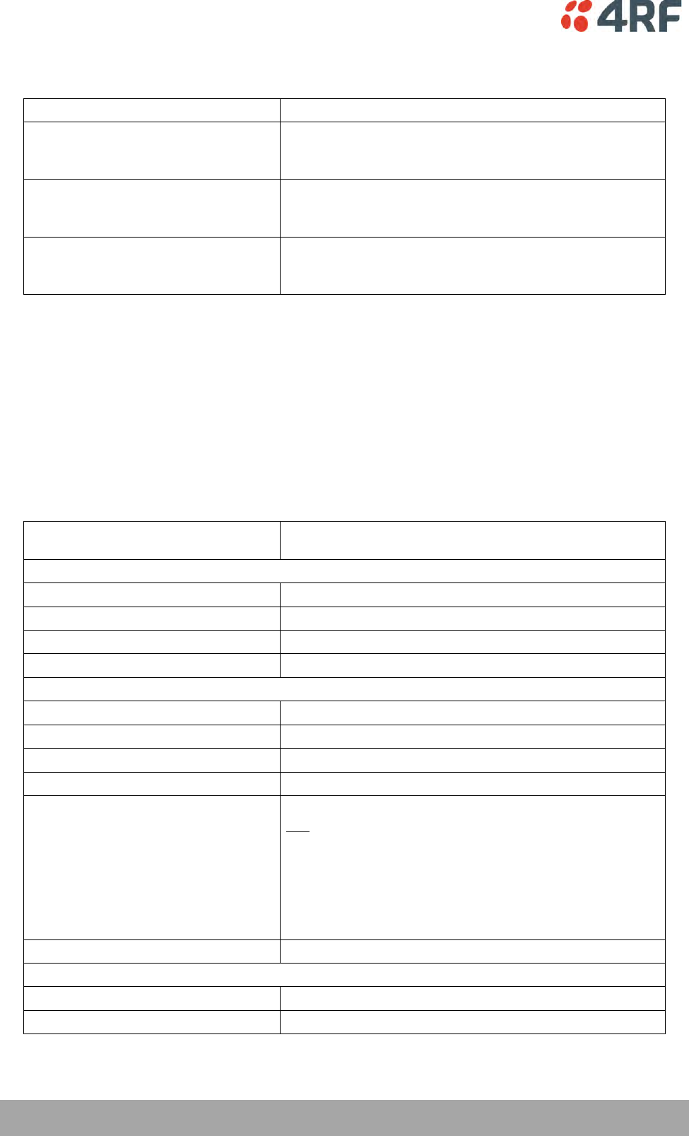
312 | Specifications
Aprisa XE User Manual
Power Consumption
Terminal Type
Power Consumption (min – max)
Standard Aprisa XE 1+0 terminal
34 to 170 W Input power
(dependent on the transmitter output power, the interface cards
fitted and the power supply option)
Standard Aprisa XE 1+1 terminal
74 to 375 W Input power
(dependent on the transmitter output power, the interface cards
fitted, the number of trib switches and the power supply option)
Standard Aprisa XE HSD terminal
68 to 286 W Input power
(dependent on the transmitter output power, the interface cards
fitted and the power supply option)
Power Consumption Model
An Aprisa XE Power Consumption model program called XEpower is on the Aprisa XE CD. This program
shows the typical power consumption for any product configuration. Java 1.6 is required to be installed on
your PC to run this program.
Standard Aprisa XE 1+0 terminal – 48 VDC
These power consumption figures represent the typical power drawn by a single standard 1400 MHz 1+0
terminal measured at the input to a ± 48 VDC power supply.
Power Consumption (min – max)
40 to 150 W Input power (dependent on interface cards fitted
and transmitter output power level)
Terminal only:
TX power of + 20 dBm
44 W
TX power of + 25 dBm
54 W
TX power of + 30 dBm
61 W
TX power of + 35 dBm
64 W
Interface cards:
QJET four port E1 card
2.3 W (four ports operating)
Q4EM four port 4W E&M card
0.6 W (all states)
QV24 four port V.24 card
0.2 W (all states)
DFXO two port 2W FXO card
0.7 W (all states)
DFXS two port 2W FXS card
One DFXS card installed with both ports idle (on hook): 2.5 W
Plus:
1.9 W / line off-hook (200 ohm copper loop plus 450 ohm
telephone)
1.0 W / line ringing (60 Vrms 25Hz source via 100 ohm copper
loop into a 1 REN load)
1.5 W / line ringing (45 Vrms 25Hz source via 100 ohm copper
loop into a 3 REN load)
HSS single port high speed data
1.0 W (all states)
MHSB:
Tributary and RF switch
13 W not switched
25 W switched

Specifications | 313
Aprisa XE User Manual
Low Power Aprisa XE 1+0 terminal – 12 VDC
These power consumption figures represent the typical power drawn by a single low power 1400 MHz 1+0
terminal measured at the input to a low power +12 VDC power supply.
Power Consumption (min – max)
34 to 53 W Input power (dependent on interface cards fitted and
transmitter output power level)
Terminal only:
TX power of + 20 dBm
34 W
TX power of + 24 dBm
40 W
Interface cards:
QJET four port E1 card
1.9 W (four ports operating)
Q4EM four port 4W E&M card
0.53 W (all states)
QV24 four port V.24 card
0.15 W (all states)
DFXO two port 2W FXO card
0.56 W (all states)
DFXS two port 2W FXS card
One DFXS card installed with both ports idle (on hook): 2.1 W
Plus:
1.6 W / line off-hook (200 ohm copper loop plus 450 ohm
telephone)
0.8 W / line ringing (60 Vrms 25Hz source via 100 ohm copper
loop into a 1 REN load)
1.2 W / line ringing (45 Vrms 25Hz source via 100 ohm copper
loop into a 3 REN load)
HSS single port high speed data
0.85 W (all states)
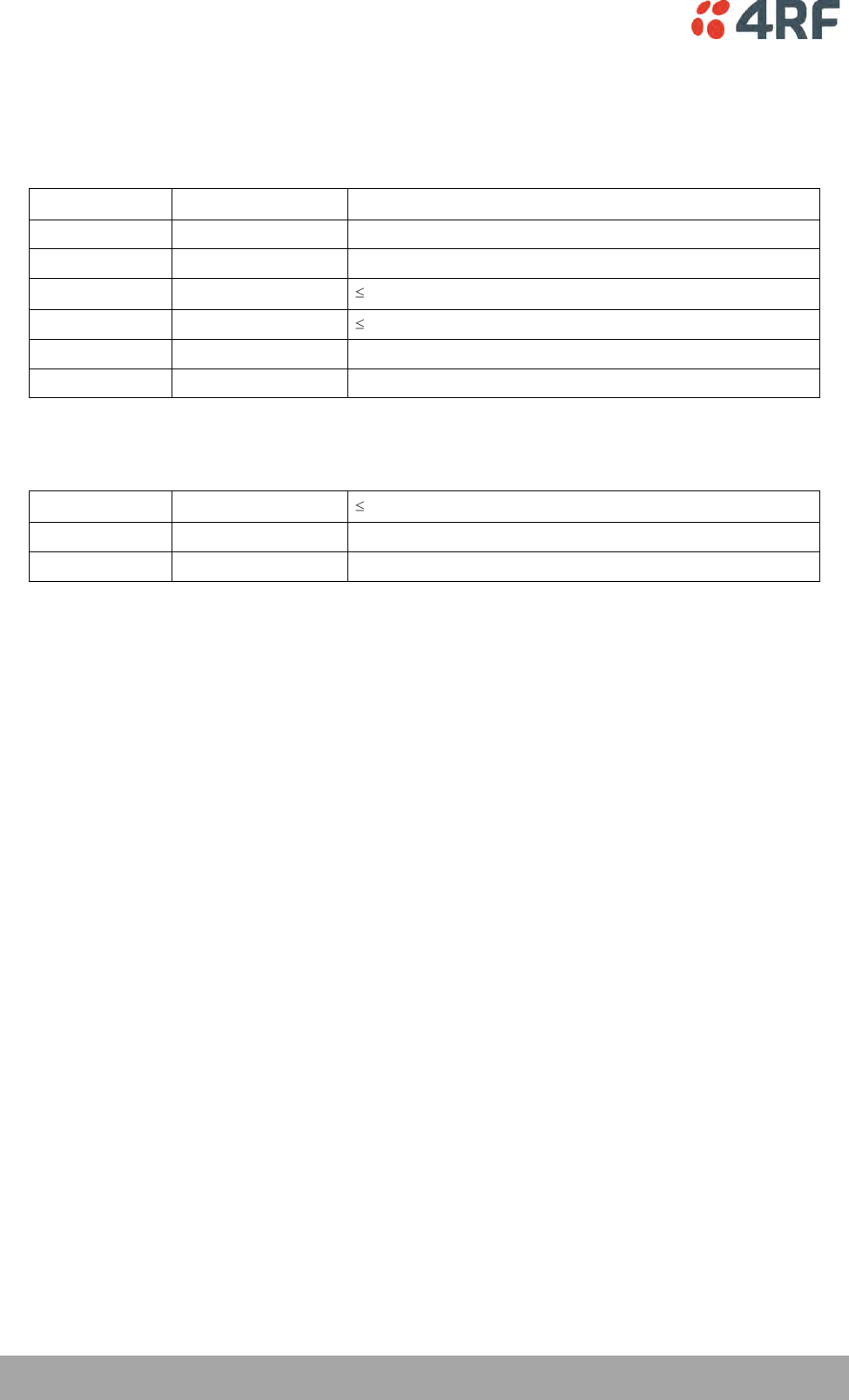
314 | Specifications
Aprisa XE User Manual
Protection System Specifications
MHSB Protection
MHSB switches
Switching time
< 25 ms from detection of alarm condition
Switch hysteresis
30 seconds (to prevent switching on short alarm transients)
RF path restore time
< 10 seconds
RF switch
TX relay / cable loss
1.0 dB
RX splitter / cable loss
4.0 dB
Total system loss
System gain reduced by a maximum of 5 dB
Tributary switch
Ports
8
HSD Protection
TX path
TX relay / cable loss
1.0 dB
Switching times
Transmit path
< 25 ms from detection of alarm condition
Receive path
Hitless
Specifications | 315
Aprisa XE User Manual
General Specifications
Environmental
Operating range
-10 to +50˚ C
Storage range
-20 to +70˚ C
Humidity
Maximum 95% non-condensing
Acoustic noise emission
59 dBA (A-weighted Sound Power Level)
Mechanical
Height
Standard terminal
2 U high (internal duplexer)
3 – 4 U high (depending on external duplexer type)
MHSB terminal
6 U high (internal duplexer)
7 – 8 U high (depending on external duplexer type)
HSD terminal
4 U high (internal duplexer)
6 – 8 U high (depending on external duplexer type)
Width
19-inch rack mount
434 mm (without mounting brackets attached)
483 mm (with mounting brackets attached)
Depth
372 mm
Colour
Pure black
Weight
Standard terminal
8 kg (internal duplexer)
9 - 12 kg (depending on external duplexer type)
MHSB terminal
25 kg (internal duplexer)
26 – 29 kg (depending on external duplexer type)
HSD terminal
17 kg (internal duplexer)
19 – 24 kg (depending on external duplexer type)
ETSI Compliance
Radio
EN 301 751, EN 300 630
EN 302 217 Parts 1, 2.1, and 2.2
EMI/EMC
EN 301 489 Parts 1 & 4
Safety
EN 60950
CSA 253147 applicable for AC, 48 VDC and 24 VDC product
variants
Environmental
ETS 300 019 Class 3.2

Product End Of Life | 317
Aprisa XE User Manual
19. Product End Of Life
End-of-Life Recycling Programme (WEEE)
The WEEE Directive concerns the recovery, reuse, and recycling of electronic and electrical equipment.
Under the Directive, used equipment must be marked, collected separately, and disposed of properly.
4RF Limited has implemented an end-of-life recycling programme to manage the reuse, recycling, and
recovery of waste in an environmentally safe manner using processes that comply with the WEEE Directive
(EU Waste Electrical and Electronic Equipment 2002/96/EC).
The WEEE Symbol Explained
This symbol appears on Electrical and Electronic Equipment (EEE) as part of the WEEE (Waste EEE)
directive. It means that the EEE may contain hazardous substances and must not be thrown away with
municipal or other waste.
WEEE Must Be Collected Separately
You must not dispose of electrical and electronic waste with municipal and other waste. You must
separate it from other waste and recycling so that it can be easily collected by the proper regional WEEE
collection system in your area.
YOUR ROLE in the Recovery of WEEE
By separately collecting and properly disposing of WEEE, you are helping to reduce the amount of WEEE
that enters the waste stream.
One of the aims of the WEEE directive is to divert EEE away from landfill and encourage recycling.
Recycling EEE means that valuable resources such as metals and other materials (which require energy to
source and manufacture) are not wasted. Also, the pollution associated with accessing new materials and
manufacturing new products is reduced.
EEE Waste Impacts the Environment and Health
Electrical and electronic equipment (EEE) contains hazardous substances which have potential effects on
the environment and human health. If you want environmental information on the Aprisa XE terminal,
contact us (on page 19).

Abbreviations | 319
Aprisa XE User Manual
20. Abbreviations
ADC Analogue to Digital Converter
ADPCM Adaptive Differential Pulse Code
Modulation
ADSL Asymmetrical Digital Subscriber
Line
AGC Automatic Gain Control
AMP Amplifier
BER Bit Error Rate
CAS Channel Associated Signalling
CPE Customer Premises Equipment
CLI Calling Line Identification
DAC Digital to Analogue Converter
dB Decibels
dBc Decibels relative to carrier power
dBm Decibels relative to 1 mW
dBr Decibels relative to the
transmission reference point
DCE Data Communications Equipment
DTE Data Terminal Equipment
DTI Digital Trunk Interface
E&M Ear and Mouth
EMC Electro-Magnetic Compatibility
EMI Electro-Magnetic Interference
ESD Electro-Static Discharge
ETSI European Telecommunications
Standards Institute
FAS Frame Alignment Signal (E1
frame)
FEC Forward Error Correction
FFE Feed Forward Equalizer
F/W Firmware
FXO Foreign Exchange Office
FXS Foreign Exchange Subscriber
GSM Global System for Mobile
communications
HSC Hardware Software Compatibility
HSS High-Speed Synchronous Serial
H/W Hardware
IC Integrated Circuit
IF Intermediate Frequency
IP Internet Protocol
I/O Input/Output
ISP Internet Service Provider
kbit/s Kilobits per second
kHz Kilohertz
LAN Local Area Network
LED Light Emitting Diode
LOS Loss of Signal
mA Milliamps
MAC Media Access Control
Mbit/s Megabits per second
MHSB Monitored Hot Standby
MHz Megahertz
MIB Management Information Base
MTBF Mean Time Between Failures
MTTR Mean Time To Repair
ms milliseconds
NFAS Not Frame Alignment Signal (E1
frame)
NMS Network Management System
OSI Open Systems Interconnection
PABX Private Automatic Branch
Exchange
PBX Private Branch Exchange
PC Personal Computer
PCM Pulse Code Modulation
PCA Printed Circuit Assembly
PLL Phase Locked Loop
POP Point of Presence
POTS Plain Old Telephone Service
ppm Parts Per Million
PSTN Public Switched Telephone
Network
PMR Public Mobile Radio
QAM Quadrature Amplitude Modulation
QPSK Quadrature Phase Shift Keying
RAI Remote Alarm Indicator
RF Radio Frequency
RoHS Restriction of Hazardous
Substances
RSSI Received Signal Strength
Indication
RX Receiver
SNMP Simple Network Management
Protocol
SNR Signal to Noise Ratio
SWR Standing Wave Ratio
TCP/IP Transmission Control
Protocol/Internet Protocol
TCXO Temperature Compensated
Crystal Oscillator
TETRA Terrestrial Trunk Radio
TFTP Trivial File Transfer Protocol
TMR Trunk Mobile Radio
TX Transmitter
UTP Unshielded Twisted Pair
VAC Volts AC
VCO Voltage Controlled Oscillator
VDC Volts DC
VoIP Voice over Internet Protocol
WEEE Waste Electrical and Electronic
Equipment

Acknowledgments and Licensing | 321
Aprisa XE User Manual
21. Acknowledgments and Licensing
The Aprisa XE product software runs the GNU Linux Operating System and incorporates several other
packages in accordance with the free software philosophy.
The following list identifies the licensed software used:
BusyBox
Description: Tiny versions of common UNIX utilities
Reference: http://busybox.net/
License Type: GNU General Public License (GPL)
DropBear SSH Server
Description: Small and secure SSH Server
Reference: http://matt.ucc.asn.au/dropbear/
License Type: MIT Style License
GoAhead WebServer 2.1
Description: Embedded Web Server
Reference: http://webserver.goahead.com/
License Type: Private License
Linux Kernel
Description: Linux Kernel version 2.4.26
Reference: http://www.kernel.org/
License Type: GNU General Public License (GPL)
Net-SNMP
Description: Various tools relating to SNMP
Reference: http://www.net-snmp.org/
License Type: CMU/UCD and BSD License
uClibc
Description: C library for embedded Linux systems
Reference: http://uclibc.org/
License Type: GNU Lesser General Public License (LGPL)
U-Boot
Description: Bootloader
Reference: http://u-boot.sourceforge.net/
License Type: GNU General Public License (GPL)

322 | Acknowledgments and Licensing
Aprisa XE User Manual
Software Licensed Under the GPL
Some of the above packages licensed under the GPL have been modified by 4RF Limited. The copyright
holders of these modified packages (including 4RF Limited) agree to them being distributed under the
terms of the General Public License.
Copies of the GNU General Public License (GPL) and Lesser General Public License (LGPL) can be obtained
from the Free Software Foundation Inc, 59 Temple Place - Suite 330, Boston, MA, 02111-1307, USA. Plain
text copies of these licenses can also be found at:
http://www.gnu.org/licenses/gpl.txt
http://www.gnu.org/licenses/lgpl.txt
If you would like a copy of the GPL source code used in this product on a CD, please send US$50.00 (to
cover the preparation of the CD and transport costs) to 4RF Limited, PO Box 13-506, Wellington, New
Zealand.
Software Licensed Under Other Licenses
The following copyright notices are included for packages not covered by the GPL:
Dropbear SSH Server (MIT License)
Dropbear—a SSH2 server
Copyright © 2002, 2003 Matt Johnston
All rights reserved
Permission is hereby granted, free of charge, to any person obtaining a copy of this software and
associated documentation files (the ‘Software’), to deal in the Software without restriction, including
without limitation the rights to use, copy, modify, merge, publish, distribute, sublicense, and/or sell
copies of the Software, and to permit persons to whom the Software is furnished to do so, subject to the
following conditions:
The above copyright notice and this permission notice shall be included in all copies or substantial
portions of the Software.
THE SOFTWARE IS PROVIDED ‘AS IS’, WITHOUT WARRANTY OF ANY KIND, EXPRESS OR IMPLIED, INCLUDING
BUT NOT LIMITED TO THE WARRANTIES OF MERCHANTABILITY, FITNESS FOR A PARTICULAR PURPOSE AND
NONINFRINGEMENT. IN NO EVENT SHALL THE AUTHORS OR COPYRIGHT HOLDERS BE LIABLE FOR ANY CLAIM,
DAMAGES OR OTHER LIABILITY, WHETHER IN AN ACTION OF CONTRACT, TORT OR OTHERWISE, ARISING
FROM, OUT OF OR IN CONNECTION WITH THE SOFTWARE OR THE USE OR OTHER DEALINGS IN THE
SOFTWARE.

Acknowledgments and Licensing | 323
Aprisa XE User Manual
Net-SNMP
Part 1: CMU/UCD (BSD like)
Copyright © 2001-2003, Networks Associates Technology, Inc
All rights reserved.
Redistribution and use in source and binary forms, with or without modification, are permitted provided
that the following conditions are met:
Redistributions of source code must retain the above copyright notice, this list of conditions and the
following disclaimer.
Redistributions in binary form must reproduce the above copyright notice, this list of conditions and the
following disclaimer in the documentation and/or other materials provided with the distribution.
Neither the name of the Networks Associates Technology, Inc nor the names of its contributors may be
used to endorse or promote products derived from this software without specific prior written permission.
THIS SOFTWARE IS PROVIDED BY THE COPYRIGHT HOLDERS AND CONTRIBUTORS ‘AS IS'' AND ANY EXPRESS
OR IMPLIED WARRANTIES, INCLUDING, BUT NOT LIMITED TO, THE IMPLIED WARRANTIES OF
MERCHANTABILITY AND FITNESS FOR A PARTICULAR PURPOSE ARE DISCLAIMED. IN NO EVENT SHALL THE
COPYRIGHT HOLDERS OR CONTRIBUTORS BE LIABLE FOR ANY DIRECT, INDIRECT, INCIDENTAL, SPECIAL,
EXEMPLARY, OR CONSEQUENTIAL DAMAGES (INCLUDING, BUT NOT LIMITED TO, PROCUREMENT OF
SUBSTITUTE GOODS OR SERVICES; LOSS OF USE, DATA, OR PROFITS; OR BUSINESS INTERRUPTION)
HOWEVER CAUSED AND ON ANY THEORY OF LIABILITY, WHETHER IN CONTRACT, STRICT LIABILITY, OR TORT
(INCLUDING NEGLIGENCE OR OTHERWISE) ARISING IN ANY WAY OUT OF THE USE OF THIS SOFTWARE, EVEN
IF ADVISED OF THE POSSIBILITY OF SUCH DAMAGE.
Part 2: Networks Associates Technology, Inc. (BSD)
Copyright © 2001-2003, Networks Associates Technology, Inc
All rights reserved.
Redistribution and use in source and binary forms, with or without modification, are permitted provided
that the following conditions are met:
Redistributions of source code must retain the above copyright notice, this list of conditions and the
following disclaimer.
Redistributions in binary form must reproduce the above copyright notice, this list of conditions and the
following disclaimer in the documentation and/or other materials provided with the distribution.
Neither the name of the Networks Associates Technology, Inc nor the names of its contributors may be
used to endorse or promote products derived from this software without specific prior written permission.
THIS SOFTWARE IS PROVIDED BY THE COPYRIGHT HOLDERS AND CONTRIBUTORS ‘AS IS'' AND ANY EXPRESS
OR IMPLIED WARRANTIES, INCLUDING, BUT NOT LIMITED TO, THE IMPLIED WARRANTIES OF
MERCHANTABILITY AND FITNESS FOR A PARTICULAR PURPOSE ARE DISCLAIMED. IN NO EVENT SHALL THE
COPYRIGHT HOLDERS OR CONTRIBUTORS BE LIABLE FOR ANY DIRECT, INDIRECT, INCIDENTAL, SPECIAL,
EXEMPLARY, OR CONSEQUENTIAL DAMAGES (INCLUDING, BUT NOT LIMITED TO, PROCUREMENT OF
SUBSTITUTE GOODS OR SERVICES; LOSS OF USE, DATA, OR PROFITS; OR BUSINESS INTERRUPTION)
HOWEVER CAUSED AND ON ANY THEORY OF LIABILITY, WHETHER IN CONTRACT, STRICT LIABILITY, OR TORT
(INCLUDING NEGLIGENCE OR OTHERWISE) ARISING IN ANY WAY OUT OF THE USE OF THIS SOFTWARE, EVEN
IF ADVISED OF THE POSSIBILITY OF SUCH DAMAGE.

324 | Acknowledgments and Licensing
Aprisa XE User Manual
Part 3: Cambridge Broadband Ltd (BSD)
Portions of this code are copyright © 2001-2003, Cambridge Broadband Ltd.
All rights reserved.
Redistribution and use in source and binary forms, with or without modification, are permitted provided
that the following conditions are met:
Redistributions of source code must retain the above copyright notice, this list of conditions and the
following disclaimer.
Redistributions in binary form must reproduce the above copyright notice, this list of conditions and the
following disclaimer in the documentation and/or other materials provided with the distribution.
The name of Cambridge Broadband Ltd. may not be used to endorse or promote products derived from this
software without specific prior written permission.
THIS SOFTWARE IS PROVIDED BY THE COPYRIGHT HOLDER ‘AS IS'' AND ANY EXPRESS OR IMPLIED
WARRANTIES, INCLUDING, BUT NOT LIMITED TO, THE IMPLIED WARRANTIES OF MERCHANTABILITY AND
FITNESS FOR A PARTICULAR PURPOSE ARE DISCLAIMED. IN NO EVENT SHALL THE COPYRIGHT HOLDER BE
LIABLE FOR ANY DIRECT, INDIRECT, INCIDENTAL, SPECIAL, EXEMPLARY, OR CONSEQUENTIAL DAMAGES
(INCLUDING, BUT NOT LIMITED TO, PROCUREMENT OF SUBSTITUTE GOODS OR SERVICES; LOSS OF USE,
DATA, OR PROFITS; OR BUSINESS INTERRUPTION) HOWEVER CAUSED AND ON ANY THEORY OF LIABILITY,
WHETHER IN CONTRACT, STRICT LIABILITY, OR TORT (INCLUDING NEGLIGENCE OR OTHERWISE) ARISING IN
ANY WAY OUT OF THE USE OF THIS SOFTWARE, EVEN IF ADVISED OF THE POSSIBILITY OF SUCH DAMAGE.
Part 4: Sun Microsystems, Inc. (BSD)
Copyright © 2003 Sun Microsystems, Inc., 4150 Network Circle, Santa Clara,
California 95054, U.S.A. All rights reserved.
Use is subject to license terms below.
This distribution may include materials developed by third parties.
Sun, Sun Microsystems, the Sun logo and Solaris are trademarks or registered trademarks of Sun
Microsystems, Inc. in the U.S. and other countries.
Redistribution and use in source and binary forms, with or without modification, are permitted provided
that the following conditions are met:
Redistributions of source code must retain the above copyright notice, this list of conditions and the
following disclaimer.
Redistributions in binary form must reproduce the above copyright notice, this list of conditions and the
following disclaimer in the documentation and/or other materials provided with the distribution.
Neither the name of the Sun Microsystems, Inc. nor the names of its contributors may be used to endorse
or promote products derived from this software without specific prior written permission.
THIS SOFTWARE IS PROVIDED BY THE COPYRIGHT HOLDERS AND CONTRIBUTORS ‘AS IS'' AND ANY EXPRESS
OR IMPLIED WARRANTIES, INCLUDING, BUT NOT LIMITED TO, THE IMPLIED WARRANTIES OF
MERCHANTABILITY AND FITNESS FOR A PARTICULAR PURPOSE ARE DISCLAIMED. IN NO EVENT SHALL THE
COPYRIGHT HOLDERS OR CONTRIBUTORS BE LIABLE FOR ANY DIRECT, INDIRECT, INCIDENTAL, SPECIAL,
EXEMPLARY, OR CONSEQUENTIAL DAMAGES (INCLUDING, BUT NOT LIMITED TO, PROCUREMENT OF
SUBSTITUTE GOODS OR SERVICES; LOSS OF USE, DATA, OR PROFITS; OR BUSINESS INTERRUPTION)
HOWEVER CAUSED AND ON ANY THEORY OF LIABILITY, WHETHER IN CONTRACT, STRICT LIABILITY, OR TORT
(INCLUDING NEGLIGENCE OR OTHERWISE) ARISING IN ANY WAY OUT OF THE USE OF THIS SOFTWARE, EVEN
IF ADVISED OF THE POSSIBILITY OF SUCH DAMAGE.

Acknowledgments and Licensing | 325
Aprisa XE User Manual
Part 5: Sparta, Inc. (BSD)
Copyright © 2003-2004, Sparta, Inc
All rights reserved.
Redistribution and use in source and binary forms, with or without modification, are permitted provided
that the following conditions are met:
Redistributions of source code must retain the above copyright notice, this list of conditions and the
following disclaimer.
Redistributions in binary form must reproduce the above copyright notice, this list of conditions and the
following disclaimer in the documentation and/or other materials provided with the distribution.
Neither the name of the Networks Associates Technology, Inc nor the names of its contributors may be
used to endorse or promote products derived from this software without specific prior written permission.
THIS SOFTWARE IS PROVIDED BY THE COPYRIGHT HOLDERS AND CONTRIBUTORS ‘AS IS'' AND ANY EXPRESS
OR IMPLIED WARRANTIES, INCLUDING, BUT NOT LIMITED TO, THE IMPLIED WARRANTIES OF
MERCHANTABILITY AND FITNESS FOR A PARTICULAR PURPOSE ARE DISCLAIMED. IN NO EVENT SHALL THE
COPYRIGHT HOLDERS OR CONTRIBUTORS BE LIABLE FOR ANY DIRECT, INDIRECT, INCIDENTAL, SPECIAL,
EXEMPLARY, OR CONSEQUENTIAL DAMAGES (INCLUDING, BUT NOT LIMITED TO, PROCUREMENT OF
SUBSTITUTE GOODS OR SERVICES; LOSS OF USE, DATA, OR PROFITS; OR BUSINESS INTERRUPTION)
HOWEVER CAUSED AND ON ANY THEORY OF LIABILITY, WHETHER IN CONTRACT, STRICT LIABILITY, OR TORT
(INCLUDING NEGLIGENCE OR OTHERWISE) ARISING IN ANY WAY OUT OF THE USE OF THIS SOFTWARE, EVEN
IF ADVISED OF THE POSSIBILITY OF SUCH DAMAGE.
GoAhead WebServer (Private License)
GoAhead WebServer
Copyright (c) 2000 GoAhead Software, Inc. All Rights Reserved
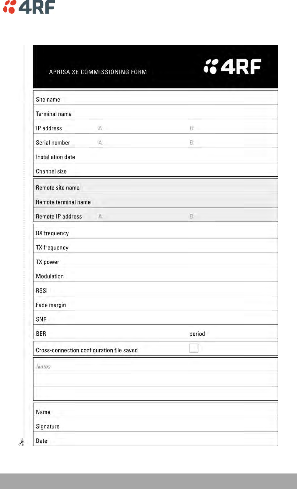
Commissioning Form | 327
Aprisa XE User Manual
22. Commissioning Form

Index | 329
Aprisa XE User Manual
23. Index
2
2 wire 105
4
4 wire 102
A
AC power supply 38
access rights 63
accessory kit 19
AIS 250
alarms
alarm summary 242
clearing alarms 247
E1 / T1 alarm conditions 250
external 33
history 244
identifying causes 248
interface alarms 246
saving history 245
termination 33
types 273
A-law 110
antennas
aligning 197
checking polarization 197
corner reflector 23
directional antennas 21, 22
installing 32
parabolic 21
selection and siting 21
siting 23
yagi 22
attenuators 41
B
balun transformer 256
basic terminal settings 72
bench setup 41
BER 203
brownout recovery module 39
browser cache, clearing 222
C
cabling
accessory kit 19
coaxial feeder 24, 41
for HSD 189
for MHSB 183
shielded 262
cache, clearing 221, 222
CAS 110, 159, 160, 161, 162
Castle Rock 83
CD contents 18
clock source
setting for 100, 131
compatibility of interfaces 156
configuration files 224
configuration, saving 87, 153
constellation analyser 205
corner reflector antenna 23
country specific settings 283
cross connections
creating 150
deleting 155
drop and insert 152
point to point 150
printing 154
saving configurations 153
selecting timeslots 164
sending configurations 153
Symmetrical Connection Wizard 174
cross connections application
about 145
ethernet capacity 148
getting configurations 149
installing 144
required system configuration for 143
toolbar 147
total assigned link capacity 145
user capacity 148
D
DC power supply 35
DCD mode 135
declaration of conformity iii
DFXO interface card 118
country specific settings 283
cross connections for 169

330 | Index
Aprisa XE User Manual
interface connections for 262
port settings for 118
signalling for 169
DFXS interface card 110
country specific settings 283
cross connections for 169
interface connections for 261
port settings for 110
signalling for 169
directional antennas 21, 22
Drop & Insert capacity 146
DSR DTR mode 134
duplexer parameters 77
E
E&M interface 102
E1
alarm conditions 250
framed 158, 159
unframed 158
earthing 24, 26, 41
environmental requirements 25
error counters 203
Ethernet
capacity 148
port status 98
Quality of Service 94
VLAN tagging 91
exchange end 118
external alarms
configuring 79
inputs 79
mapping 81
outputs 81
F
fade margin 202
fault finding 201, 239, 251
feeder cables 24
framed mode 158
framed modes
PCM30C mode 159
PCM31C mode 159
T1 ESF modes 161, 162
T1 SF modes 160
frequency bands 27
frequency bands ETSI 285
front panel
connections 29
indicators 29
tributary switch 180
G
gateway
factory default 62
H
handshaking
DCD mode 135
DSR DTR mode 134
RTS CTS mode 133
hardware
accessory kit 19
installing 31, 32
hitless 188
HSD 188
cabling 189
configuring terminals 191
IP addresses 190
HSS clocking
clocking types 137
cloud mode 141
internal clocking 137
pass-through clocking 137
pipe mode 138
primary/secondary master clocking 137
synchronous clock selection modes 136
HSS interface card 131
cross connections for 172
handshaking 133
interface connections for 263
port settings for 131
humidity 25
I
image files 226
updating table of 230
in-service commissioning 195
installation 31, 33
interface cabling 34
interface cards
before installing 234
configuring 90
installing 236
port settings 90
summary 89
types 30
interface connections 255
DFXO 262

Index | 331
Aprisa XE User Manual
DFXS 261
Ethernet 257
HSS 263
Q4EM 258
QJET 256
QV24 271
QV24S 271
interface pinouts
HSS 263
interface traffic direction 255
interfaces, compatibility 156
IP address
factory defaults 62
network 52
terminal 73
understanding 51
J
Java
clearing cache 221
requirement for 18, 47, 143
L
LEDs
identifying colours 248
interface 256, 257, 258, 261, 262, 263
RF protection switch 182
tributary protection switch 181
lightning protection 26
link budget 24
link capacity, assigned 146
link performance 201, 205
LOF 250
logging in
SuperVisor 58
Loop interface circuits 105
loopbacks
about 239
interface lookbacks 240
timeslot loopbacks 241
LOS 250
M
maintenance 211
major alarms, mapping 81
management
ethernet capacity 148
MHSB 179
cabling 183
clearing alarms for 187
configuring radios for 184
configuring the terminals 186
front panel
RF protection switch ................... 181
hot stand-by 179
IP addressing 184
monitored hot stand-by 179
mounting 185
power supply 183
slave tributary switch 182
standby mode 181
tributary switch
front panel ............................... 180
MIB
saving 87
minor alarms, mapping 81
modify user group 63
mounting kit 19
O
operating temperature 25
P
passwords
changing 65
path planning 21
path propagation calculator 21
PCM modes 158, 159, 160, 161, 162
performance, of link 201, 205, 206
performance, save history 207
pinouts 262
DFXS 261
Ethernet 257
Q4EM 258
QJET 256
QV24 271
QV24S 271
Synchronous cable assemblies 264
POTS 105, 110, 118
power
AC power 38
DC cabling 36
DC power 35
power supply 25, 35
powering up 196
protected terminals
HSD 188
MHSB 179

332 | Index
Aprisa XE User Manual
Q
Q4EM interface card
cross connections for 168
E&M signalling types 259
interface connections for 258
port settings for 102
QJET interface card
cross connections for 157
interface connections for 256
modes 158, 159, 160, 161, 162
port settings for 100
Quality of Service (QoS) 94
QV24 interface card 126, 127
baud rate 170
cross connections for 170
interface connections for 271
port settings for 126, 127
QV24S interface card 128
interface connections for 271
port settings for 128
R
rack space 31
RAI 250
rebooting the terminal 231
receiver 28
RF protection switch
front panel 181
LEDs 182
RF settings 67
modem performance 70
RS-449 synchronous data 131
RS-530 synchronous data 131
RSSI
alarm threshold 78
aligning the antennas 199
RTS CTS mode 133
S
safety earth 40
setup menu
COM port settings 44
Hyperterminal 44
setup basic settings 55
signalling mode 169
slots
configuring 238
terminal 30
SNMP 83
MIB details 86
setting access controls 84
setting trap destinations 85
viewing traps 86
Space Diversity 188
specifications 285
auxiliary interfaces 308
DFXO interface 303
DFXS interface 305
environmental 313
ethernet interface 300
ETSI 313
external alarms interface 308
general 313
HSS interface 308
MHSB 312
Q4EM interface 302
QJET interface 301
QV24 interface 307
QV24s interface 307
static damage, avoiding 236
storage temperature 25
subnet mask
factory default 62
subscriber end 110
SuperVisor 57
logging into 58
logging out 59
opening page 60
PC requirements for 47
PC settings for 48
Surveyor 21
syslog 251
error logging 251
remote logging 253
system performance specifications
ETSI 285
T
T1
alarm conditions 250
framed 158, 160, 161, 162
unframed 158
temperature 25
terminal
alarm summary 242
applying power 196
clocking 74
earthing 26, 40, 41
installing 31
logging into 58

Index | 333
Aprisa XE User Manual
logging out 59
modules 28
near and far, explained 51
operating conditions 25
power supplies 35
rebooting 231
upgrading 224
terminal emulator 87
test equipment 204
TFTP server 219
timed reboot 231
timeslots
PCM modes 159
selecting 164
tools 31
traffic direction of interfaces 255
tranformer, Balun 256
transmitter 28
tributary switch
LEDs 181
troubleshooting 239
U
unframed mode 158
upgrading the terminal
uploading system files 224
user ethernet capacity 148
users
access rights 63
adding 63
changing passwords 65
deleting 64
disabling 64
saving user information 64
session details 65
user groups 63
view user group 63
V
V.24
serial data 126, 127, 128
V.35 synchronous data 131
W
web browser cache, clearing 222
WEEE 315
X
X.21 synchronous data 131